Even with all the restoration books I have read, and with all the e-mail exchanges, no one prepared me for the fact that I would develop a phobia about touching the car now that it has finally arrived! I am afraid to touch the thing for fear of scratching it!
My plan is to begin with the brake and fuel lines, then move to some of the interior dynamat installation followed by the electrical wiring harness. Along the way I am sure there will be diversions to other bits and pieces. I will try to be disciplined about this process and avoid the temptation to just start attaching pieces to show progress. Although I am confidant that I will succumb to that diversion from time to time!
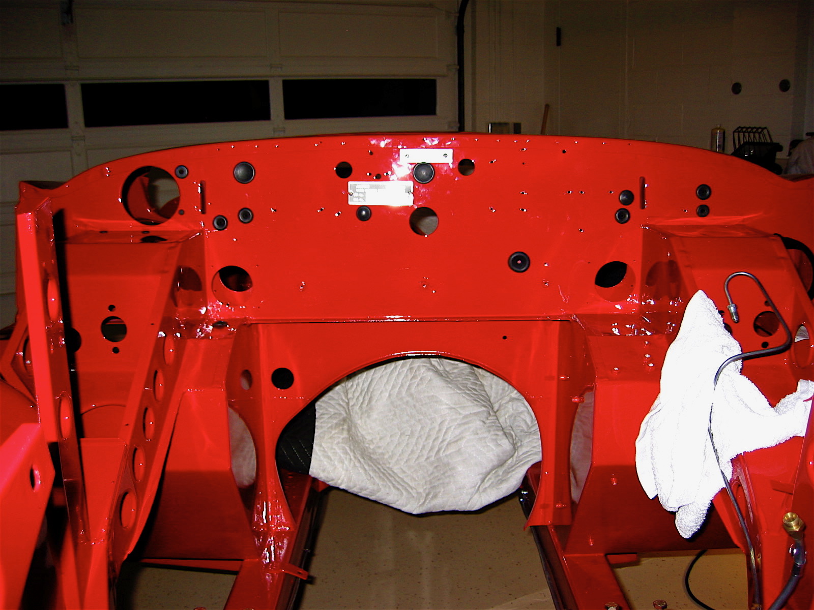
It seemed entirely appropriate that the very first components to be installed should be the two production identification number plates on the firewall. These were produced by Clarke Spares and Restorations. The original ID plates had to be shared with them before they would produce new plates.
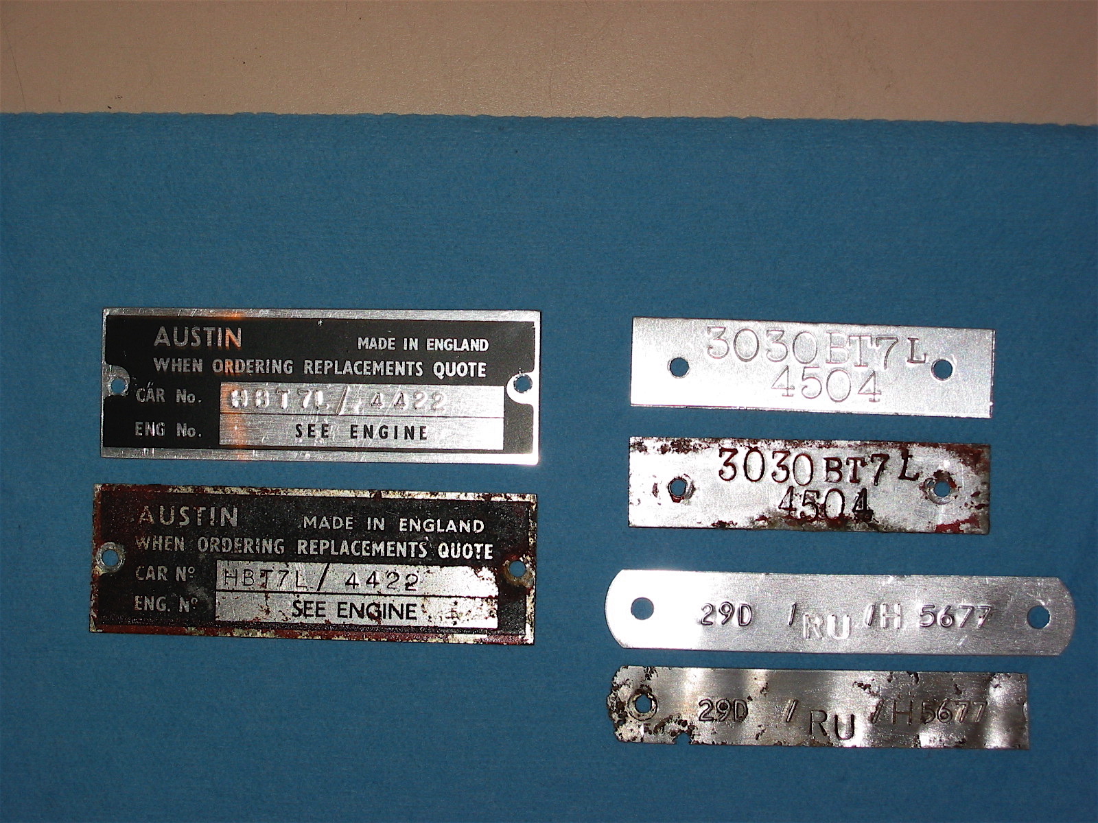
Number plates
I.D. Number Plates
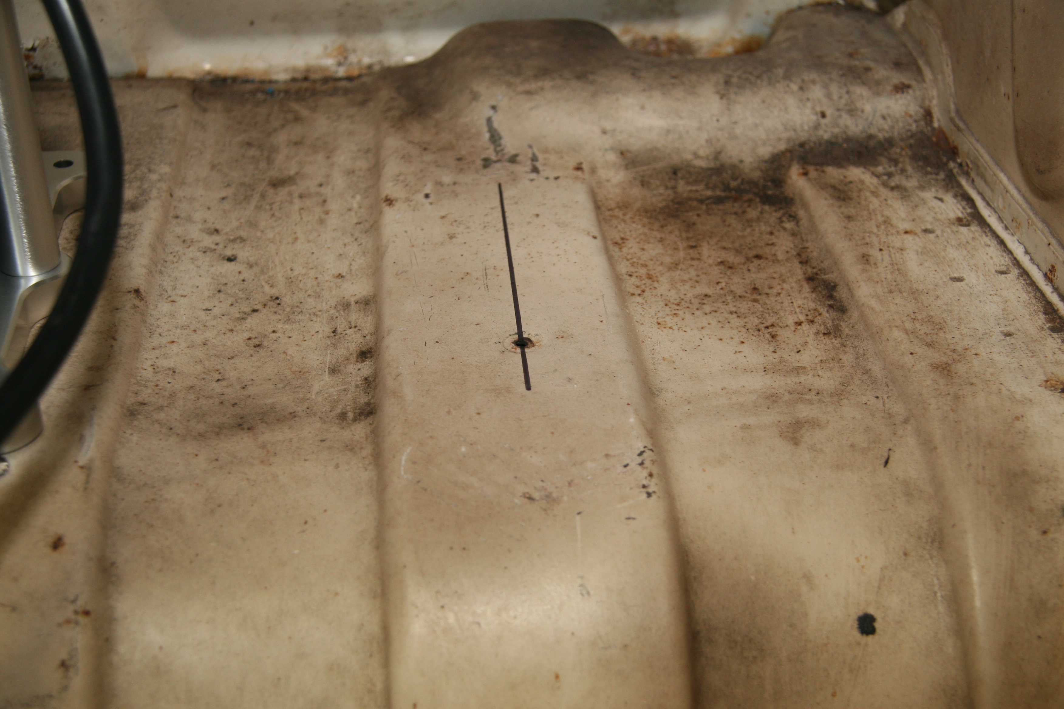
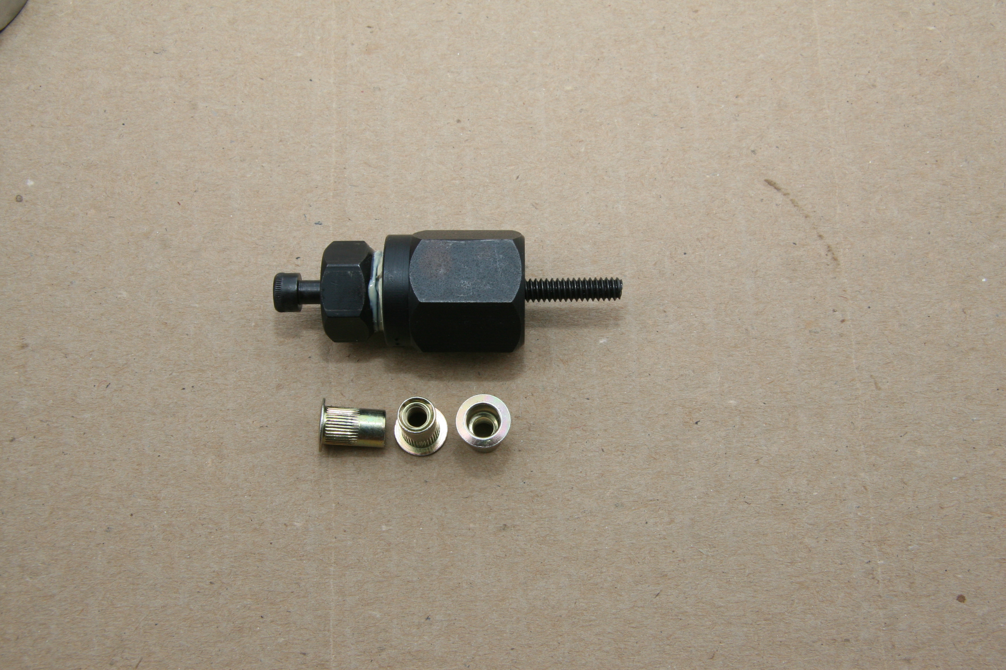
Then I began by chasing the threads on all fixed nuts throughout the car to eliminate primer and paint before securing fasteners. Just that little job took about 2 1/2 hours.
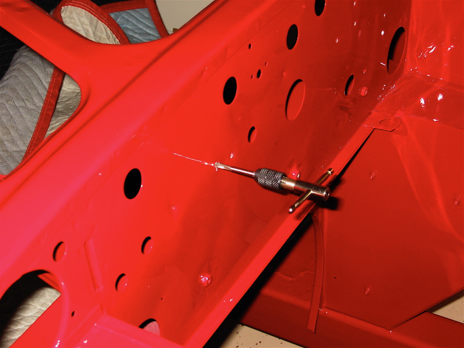
chasing threads
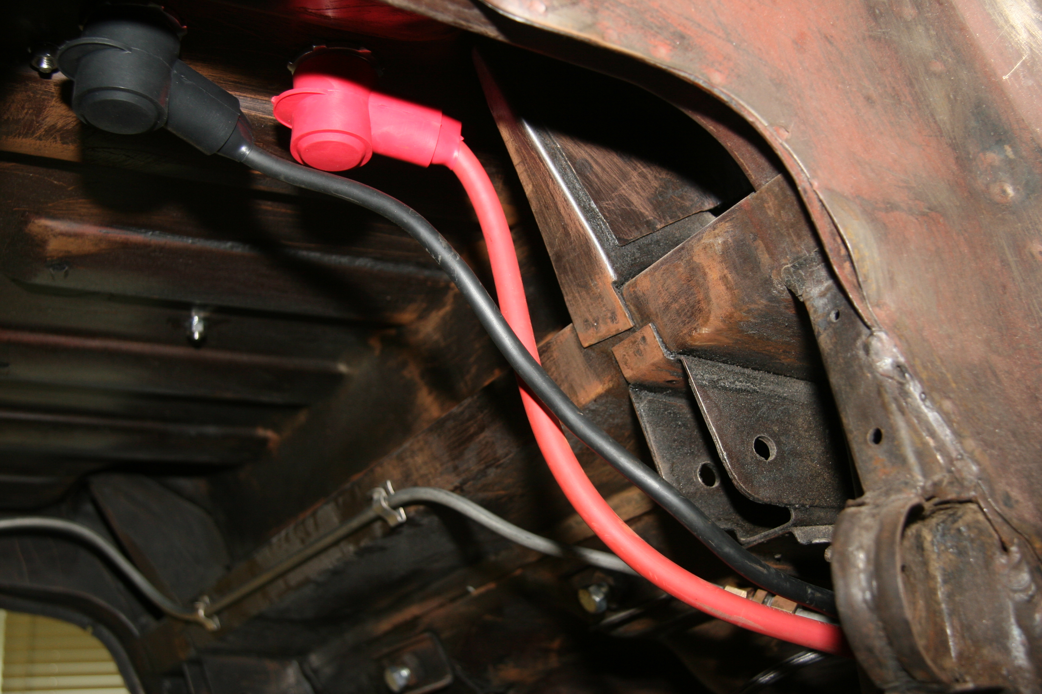
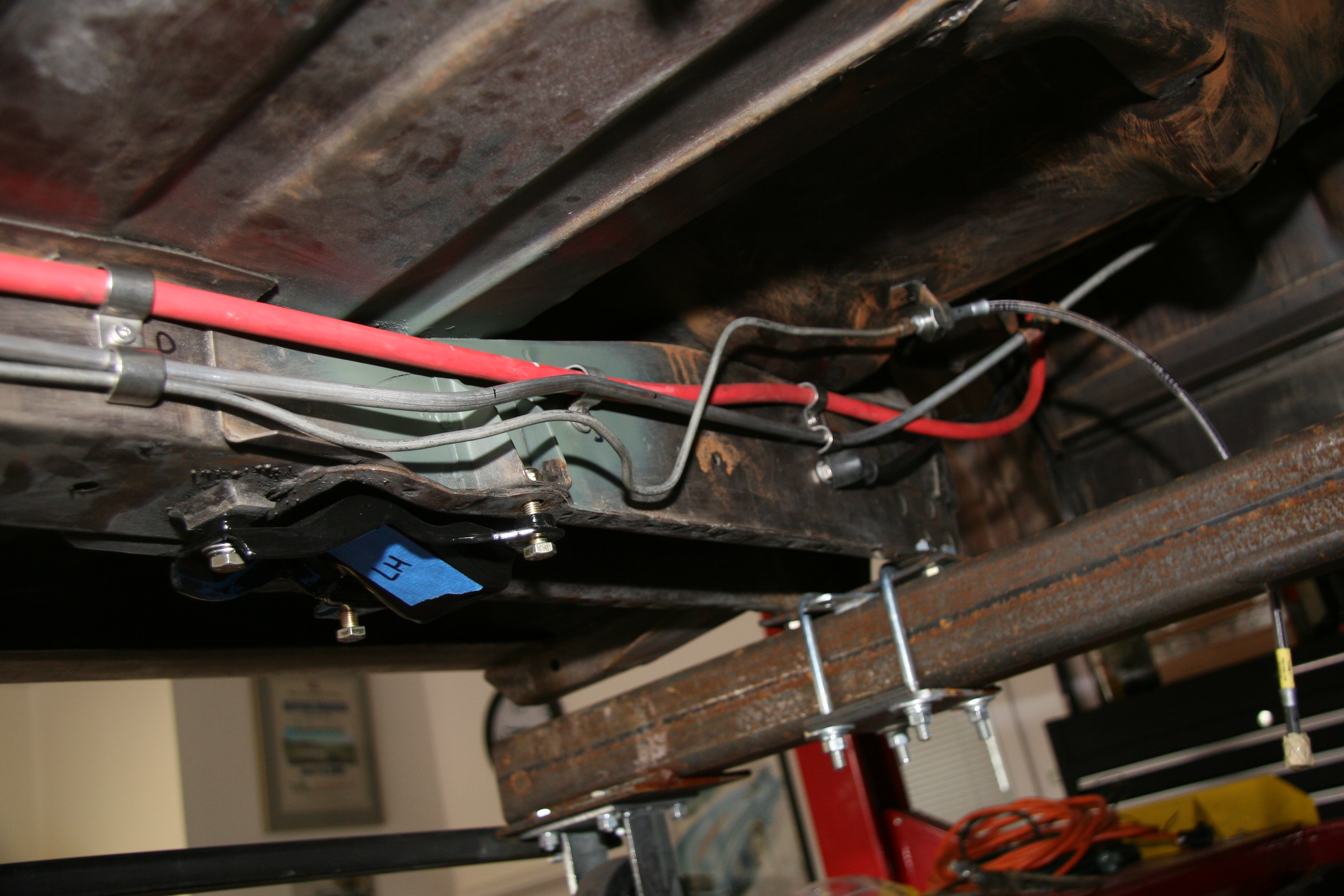
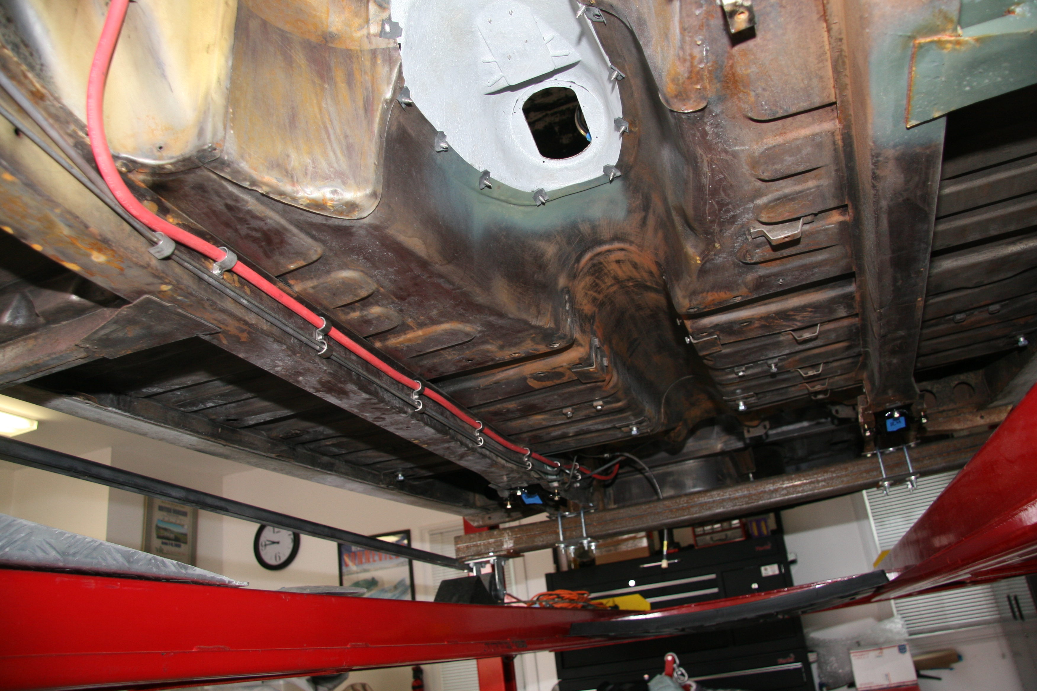
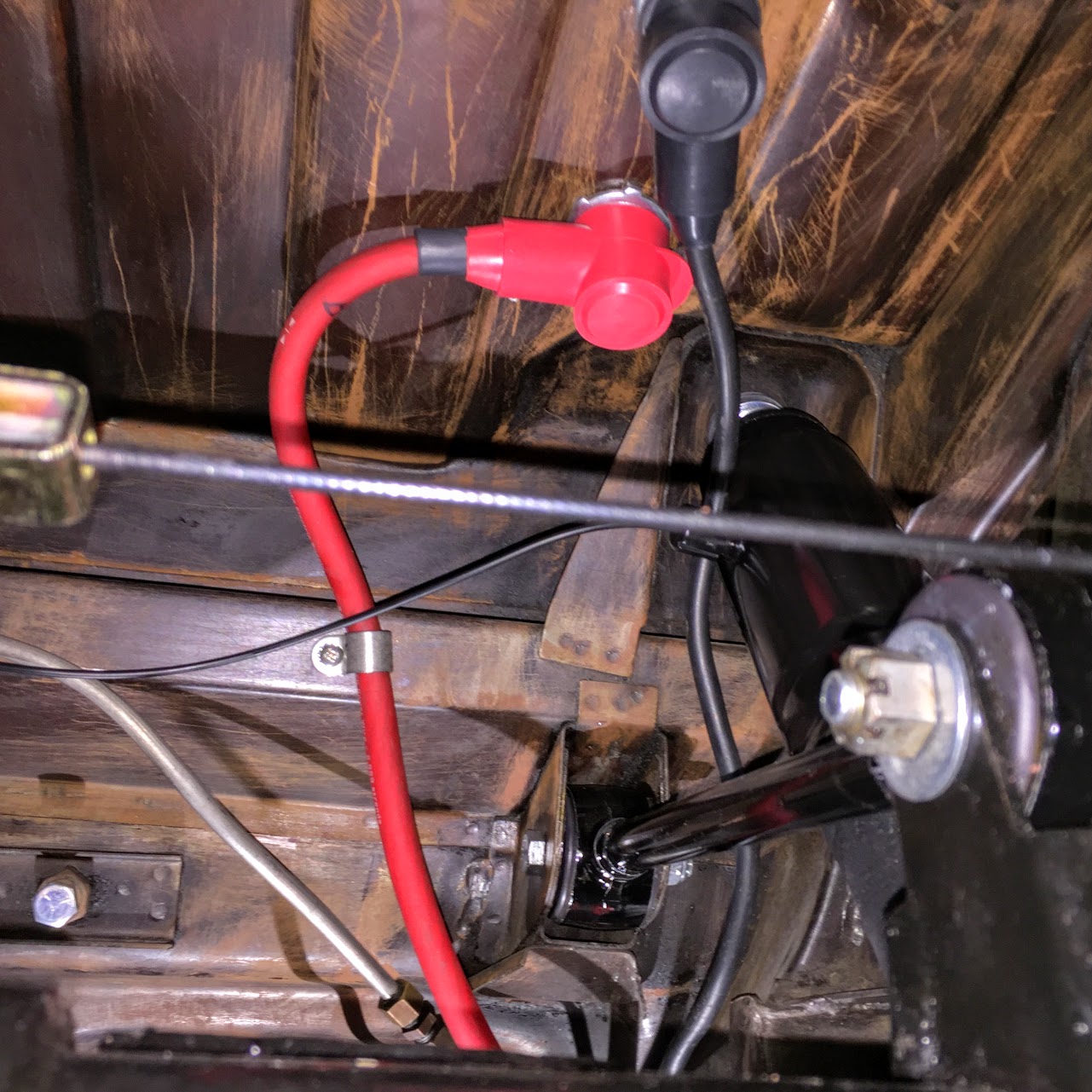
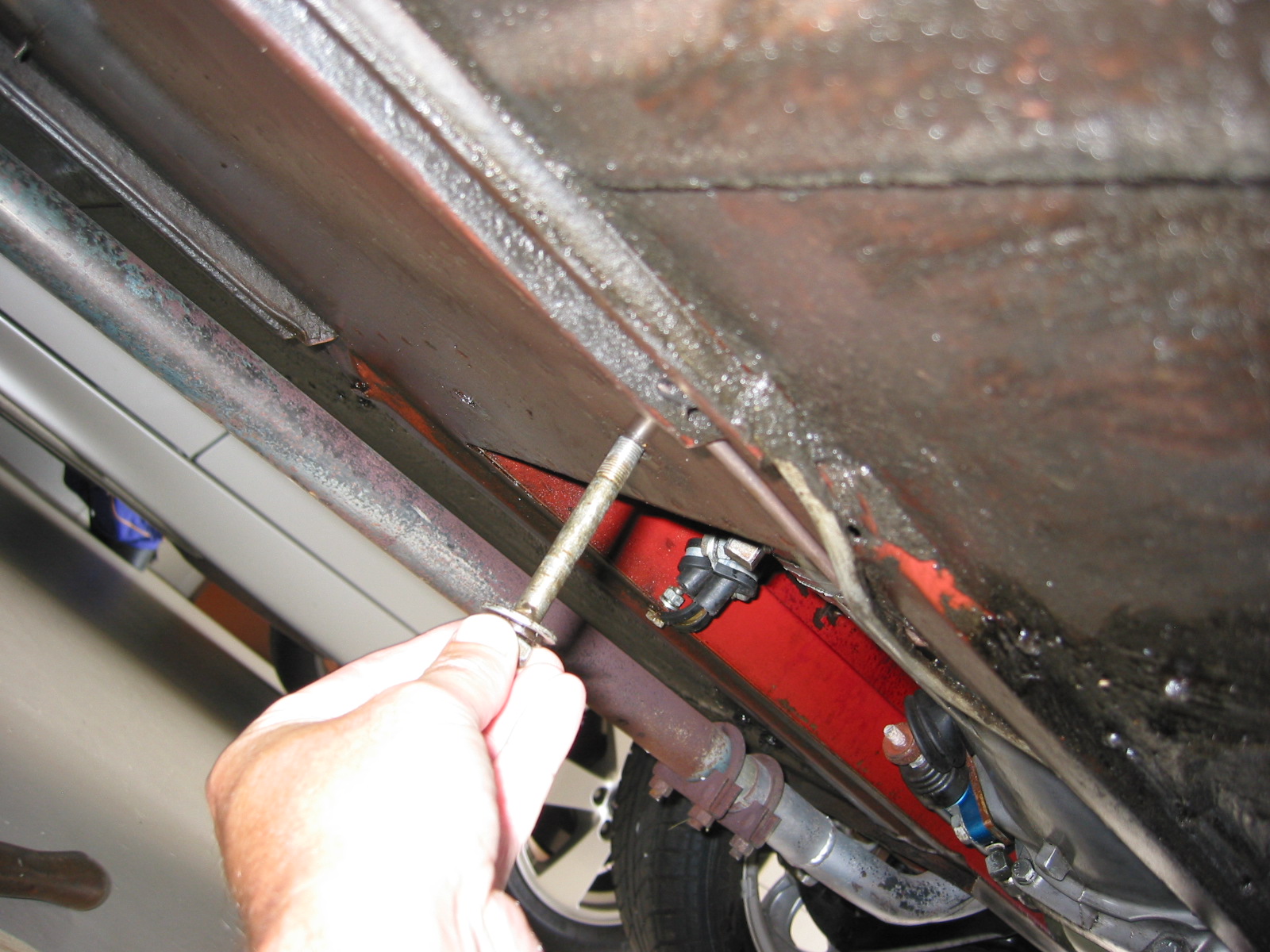
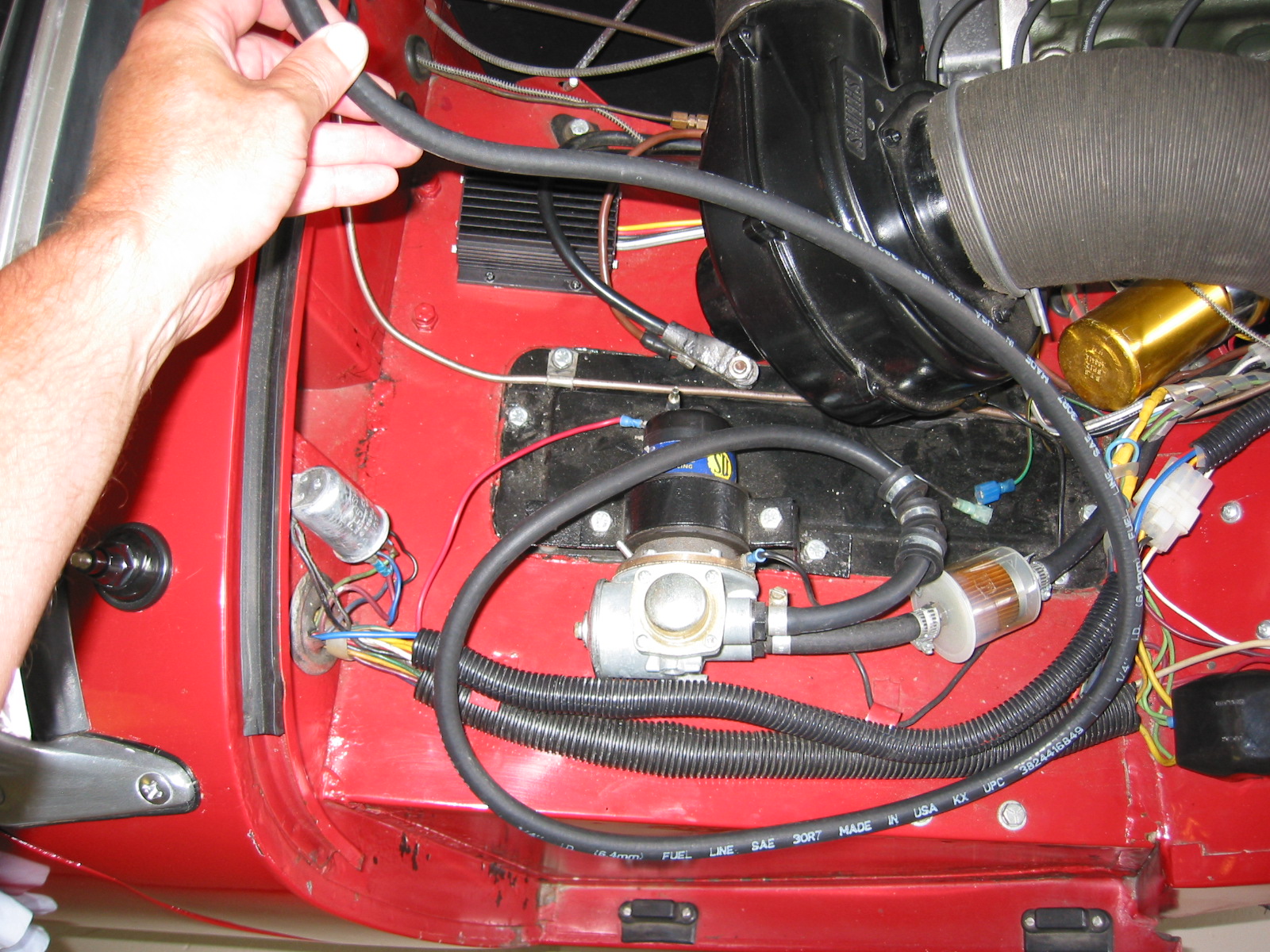
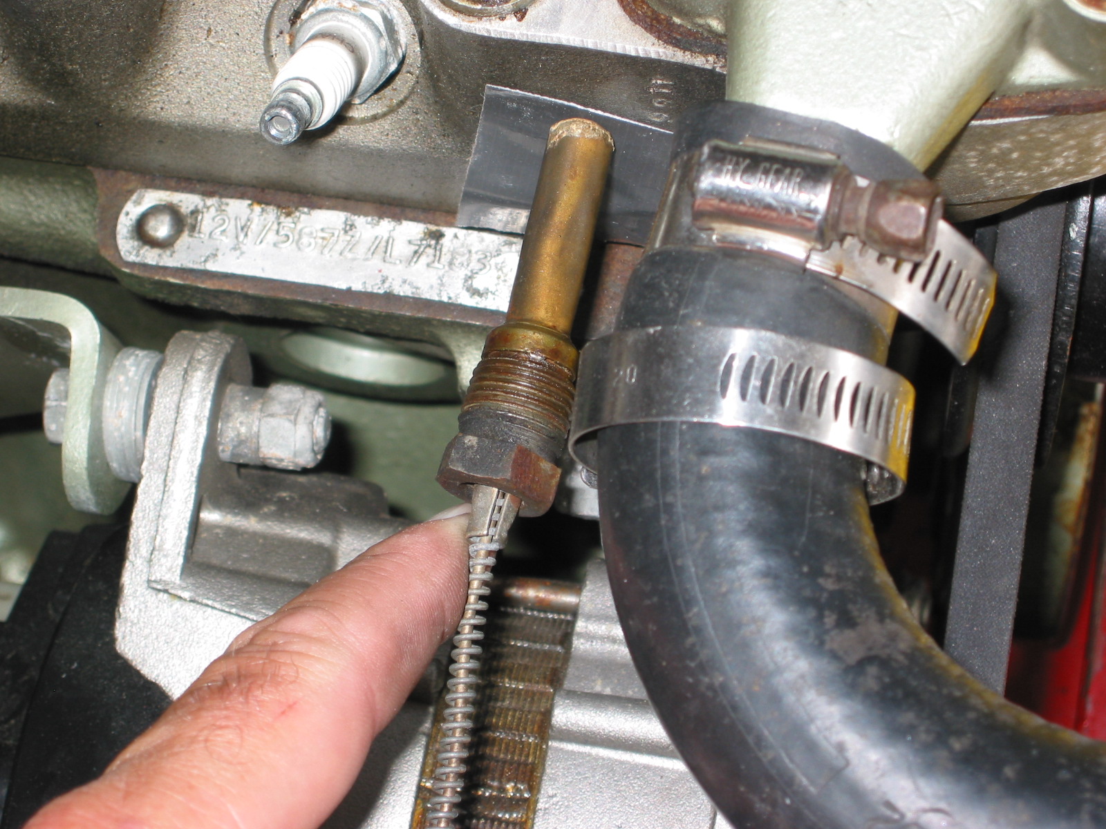
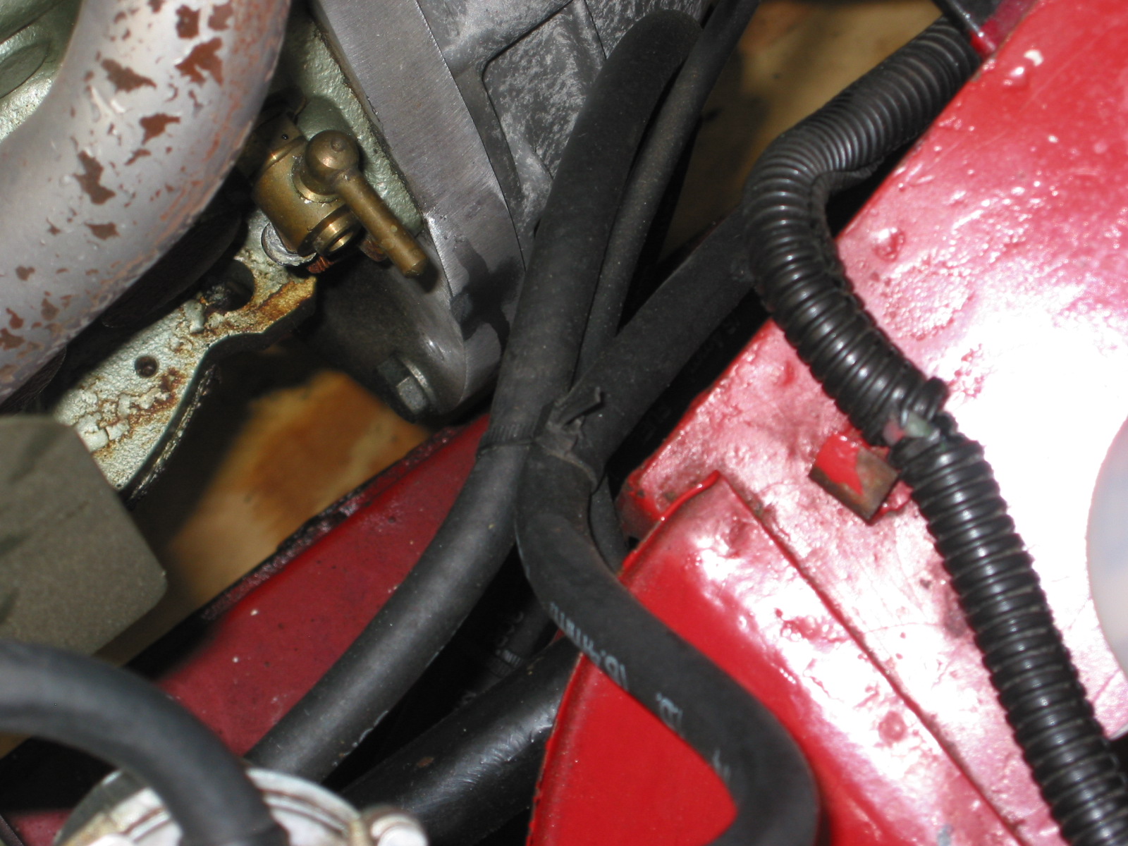
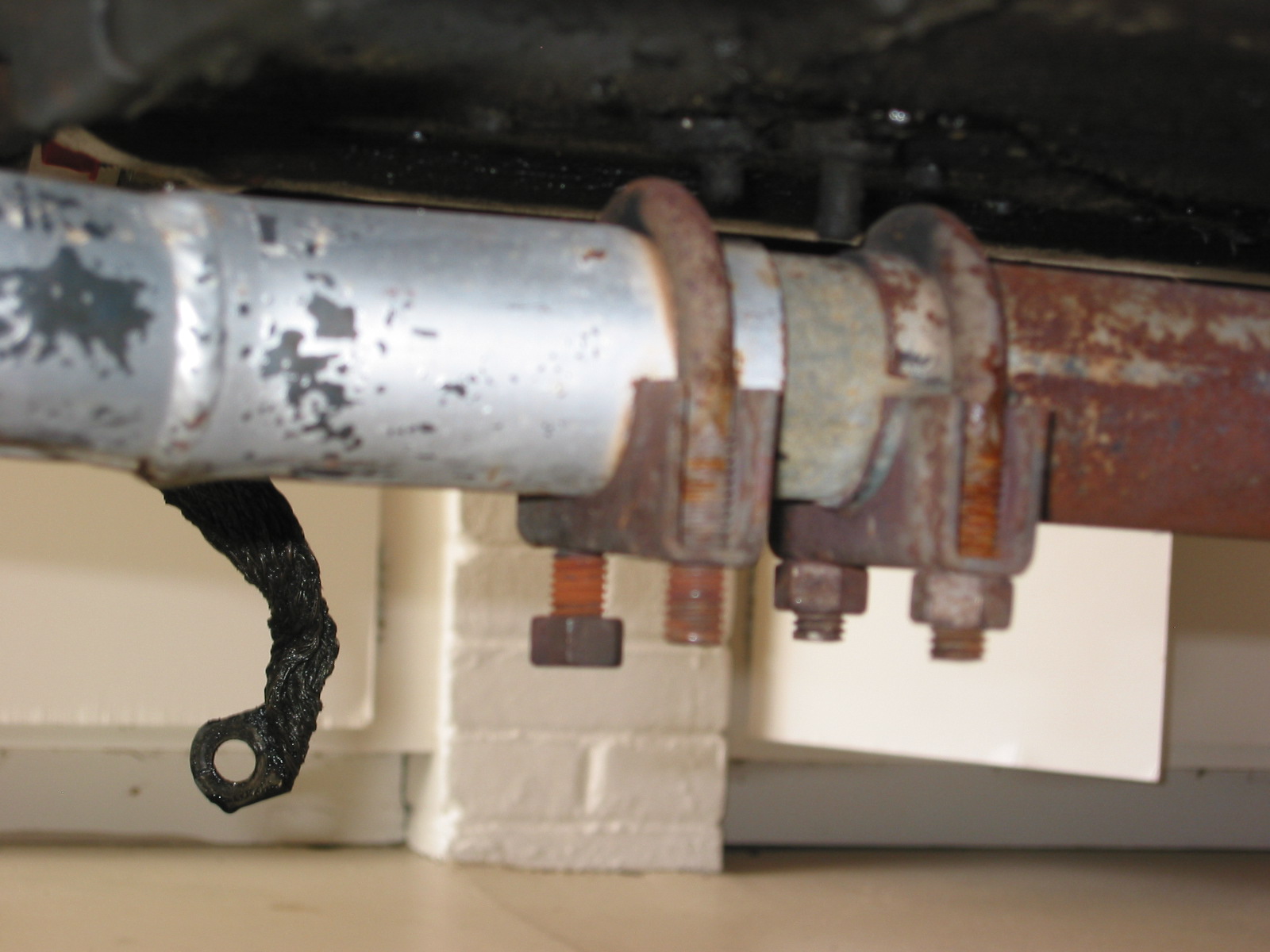
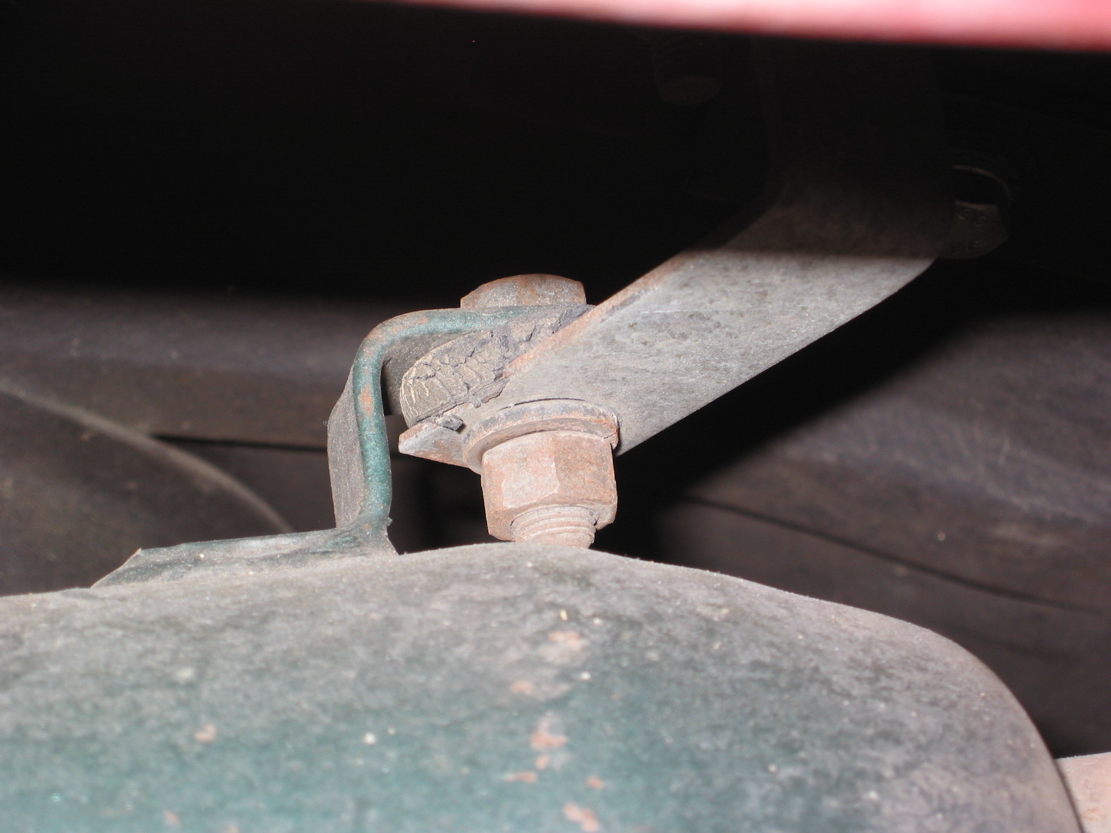
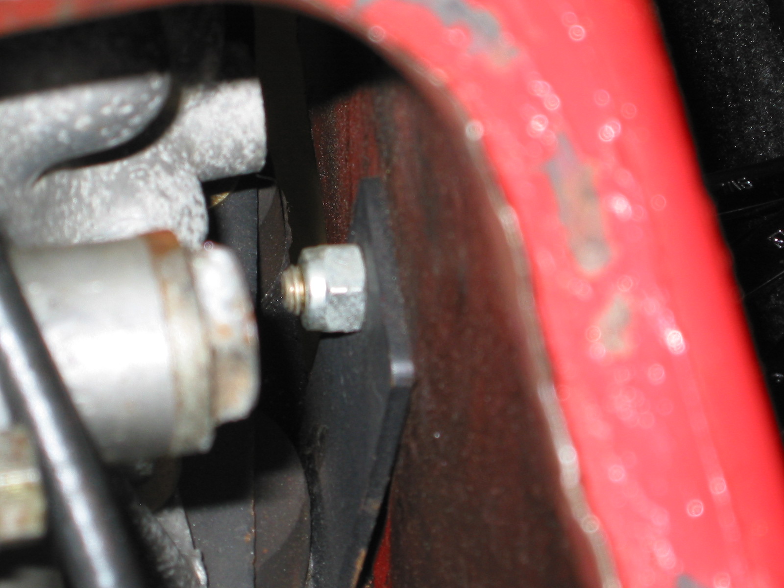
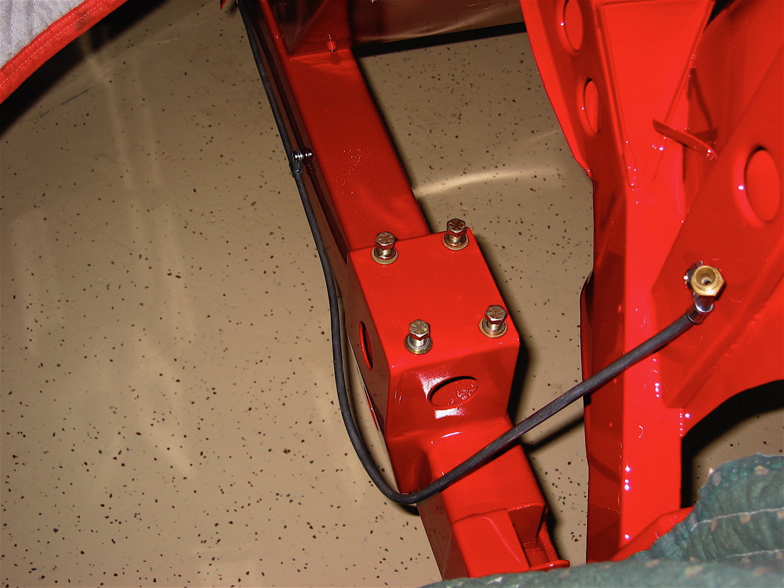
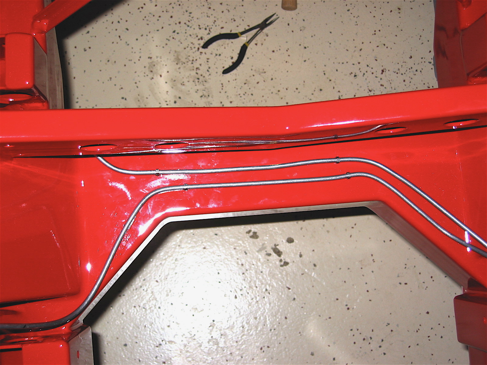
Then it was on to the hydraulic lines. Fuel line first, followed by the brake junction and the brake lines and the line to the clutch master cylinder. Having drilled all the mounting holes after the frame arrived from Martin, this job moved along very quickly.
Fuel line 1
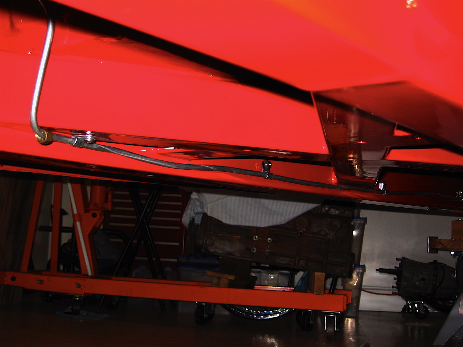
Fuel line 2
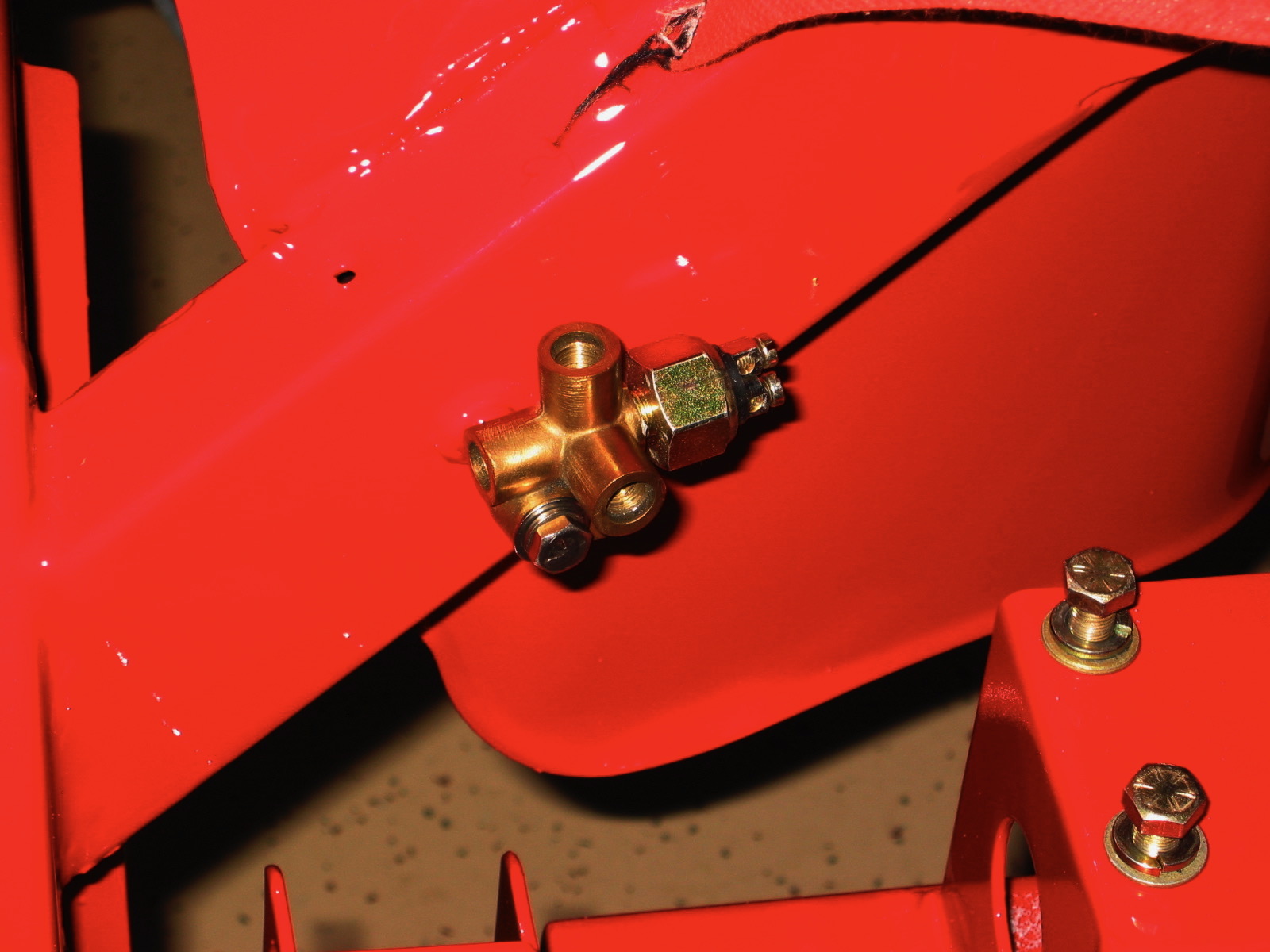
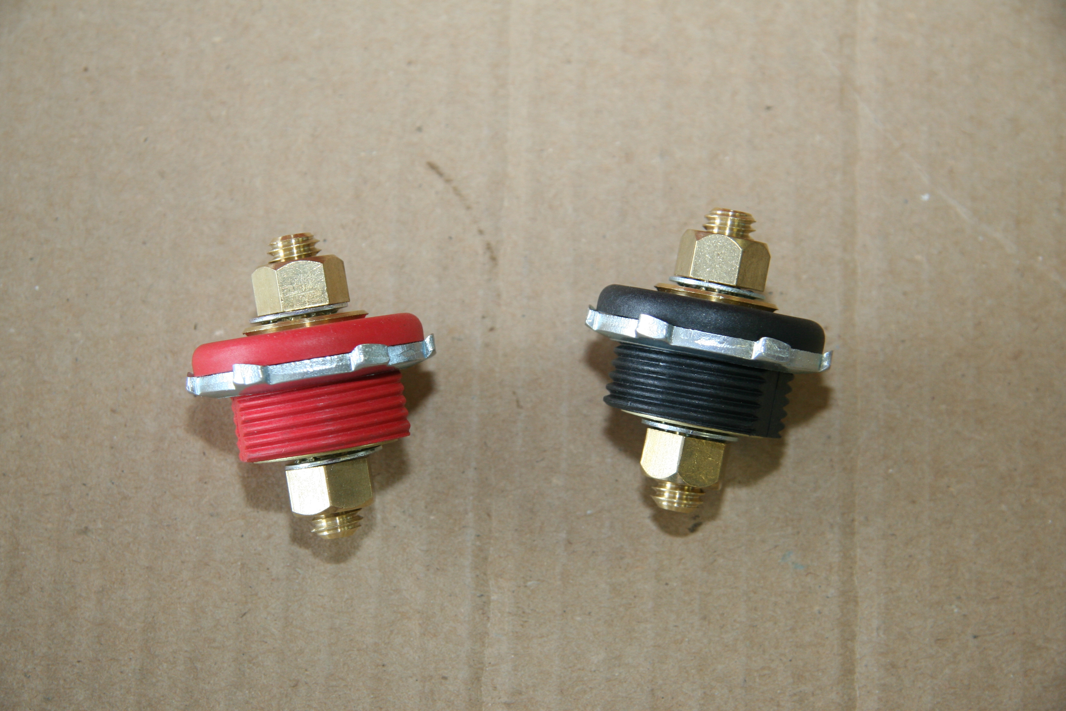
brake pipe union
Brake line 2
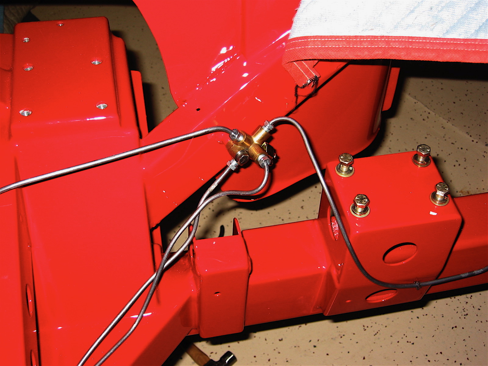
Brake lines at union
Front brake lines
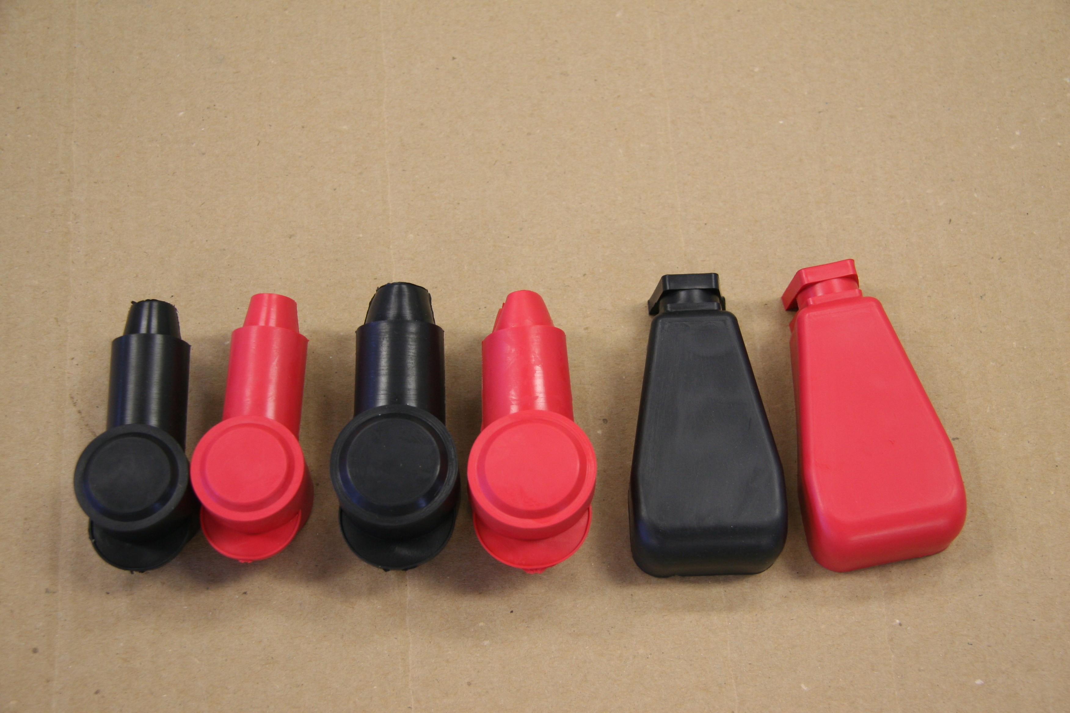
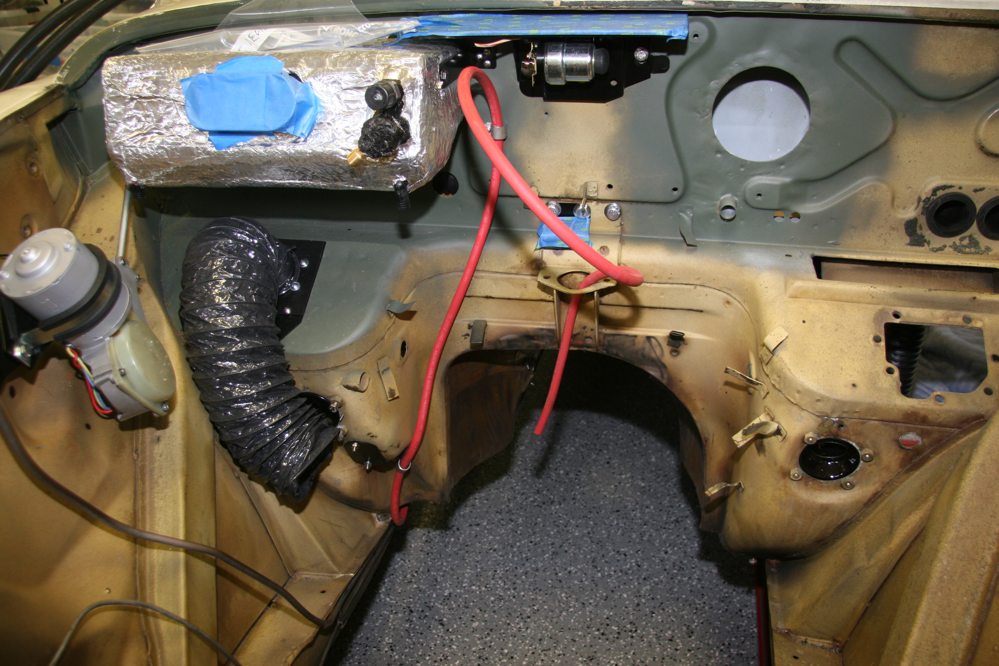
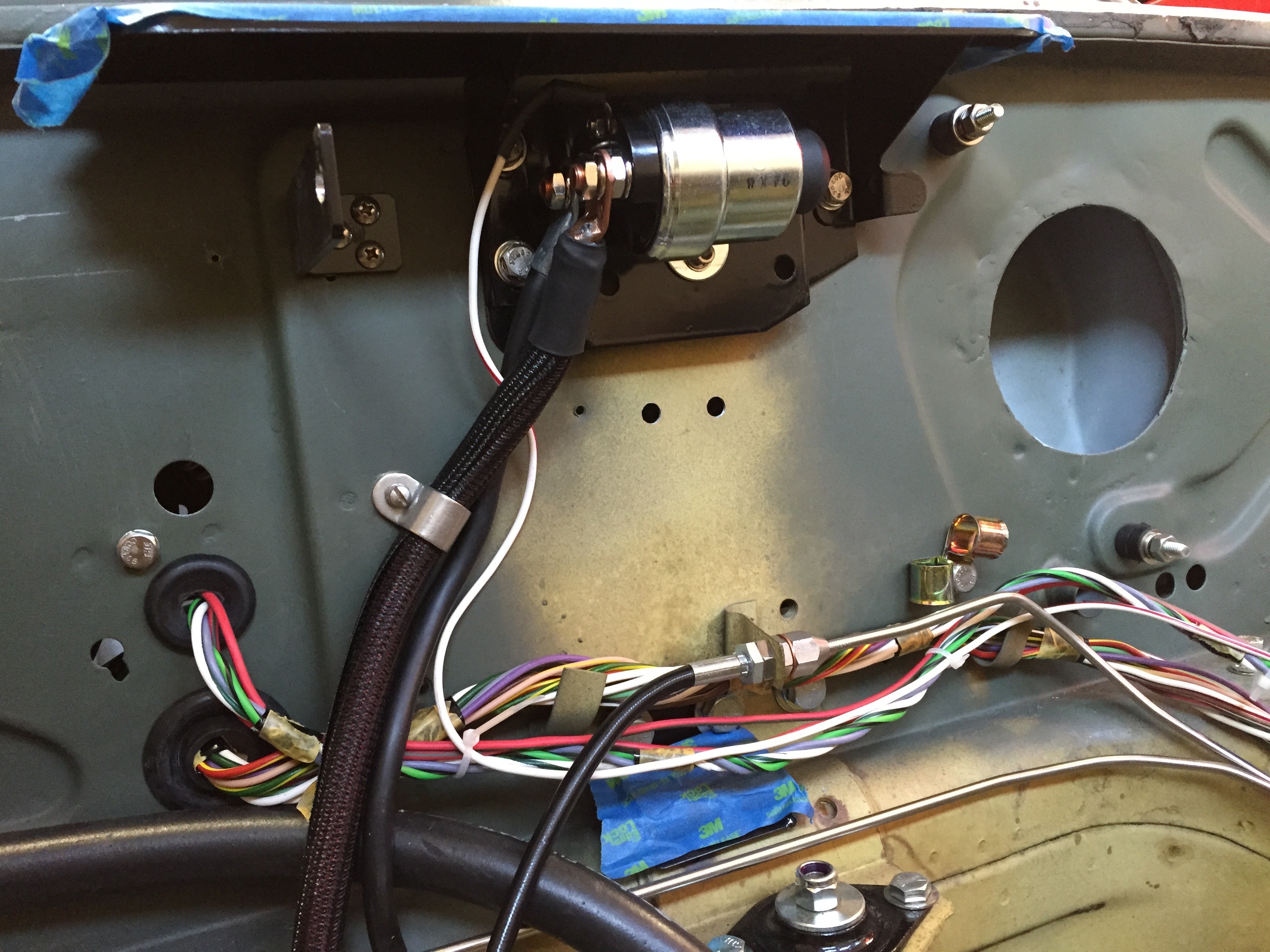
My first two diversions were the horn brackets and the air intake flange. These were installed next. Then came the firewall rubber grommets, and again this job was made easier because I had pre-fit and numbered these at an earlier stage.
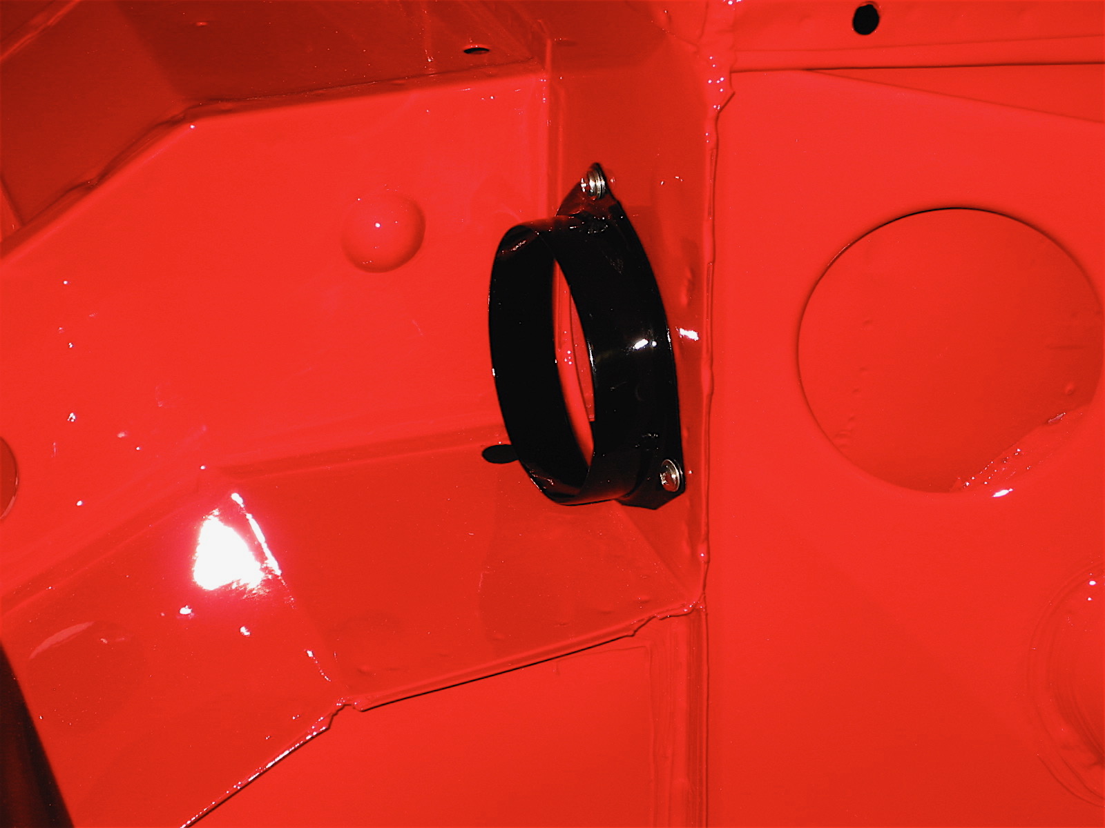
air intake flange
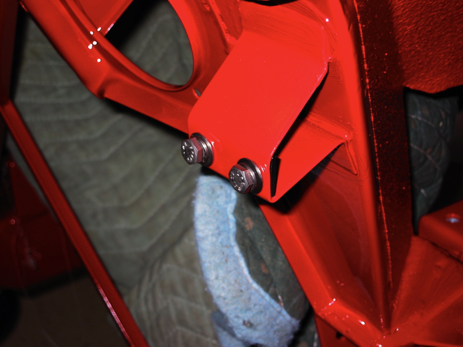
Horn bracket
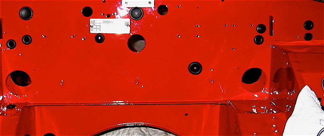
rubber firewall grommets
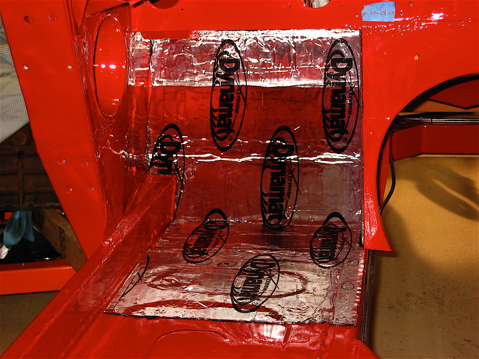
I moved on to beginning the process of controlling interior cabin heat and improving sound insulation. Fred Wescoe produced an excellent piece on interior insulation that proved very helpful. Making your Healey Cool Fred Wesco .
Our cars originally used a tar paper product and jute under the carpet for this purpose, but contemporary products provide much improved insulating qualities. On the advice of others I decided to use a product called Dynamat Exteme that has a very sticky adhesive rubber type surface on the underside and a foil surface on the top. After making patterns from butcher paper the individual pieces were easy enough to cut just using scissors. They were then carefully applied and rolled on with a wallpaper seam roller. Aluminum tape was used to seal all of the seams. All of this produces a nice looking appearance that will hopefully keep the heat down in the cockpit.
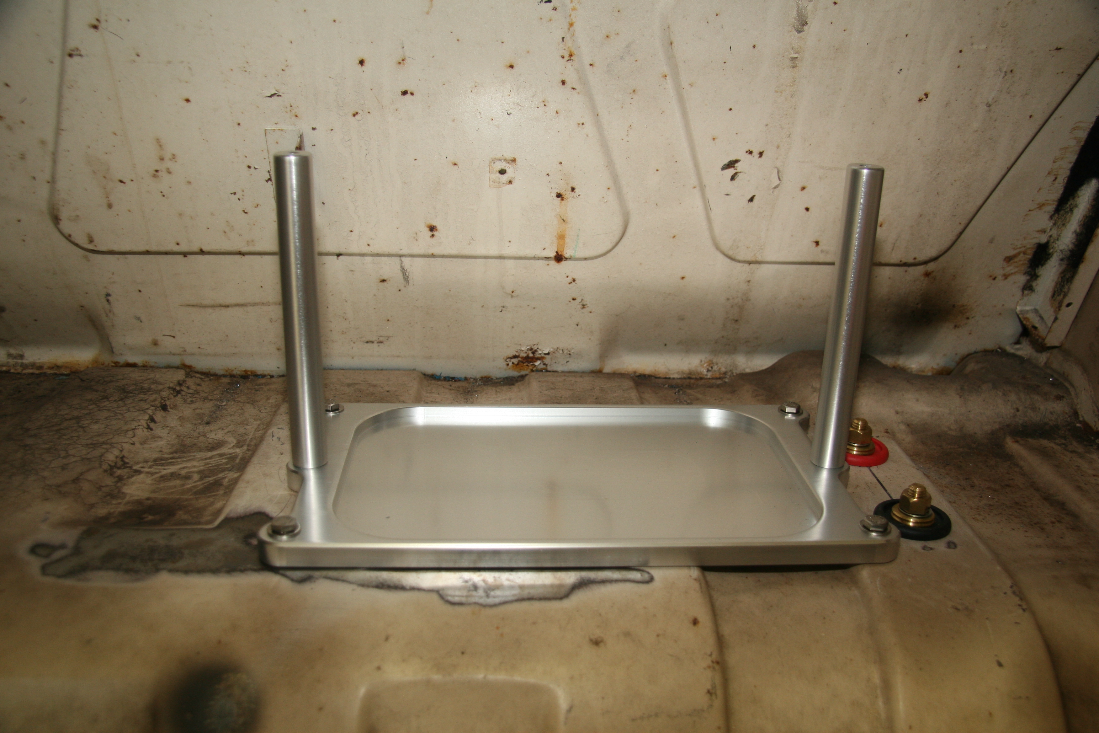
The installation of the first piece of the dynamat extreme went under the car, below the driver’s seat and above the muffler insulation panel. Then the stock insulation panel was secured using the six studs through the floor.
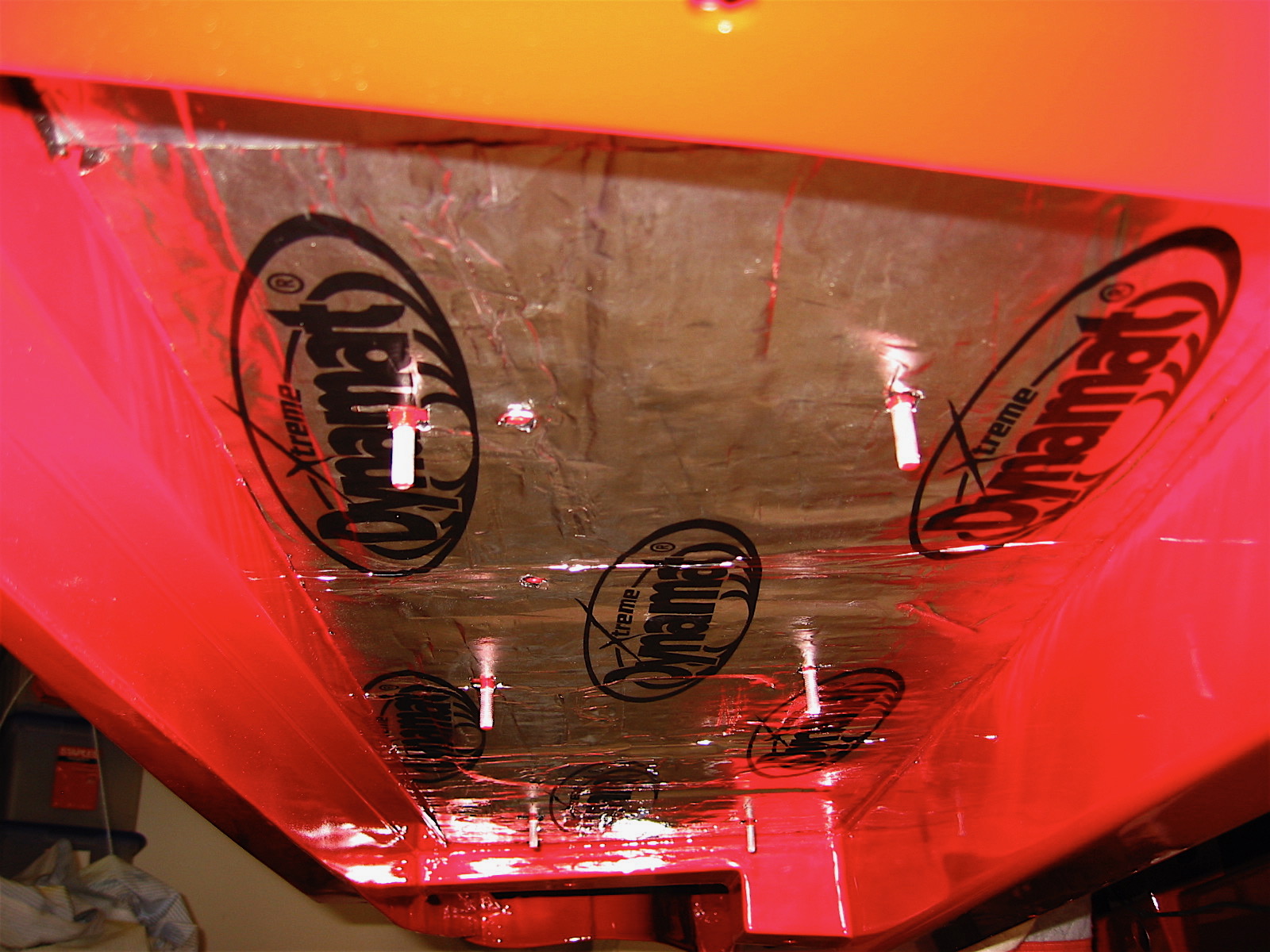
Dynamat Extreme 1
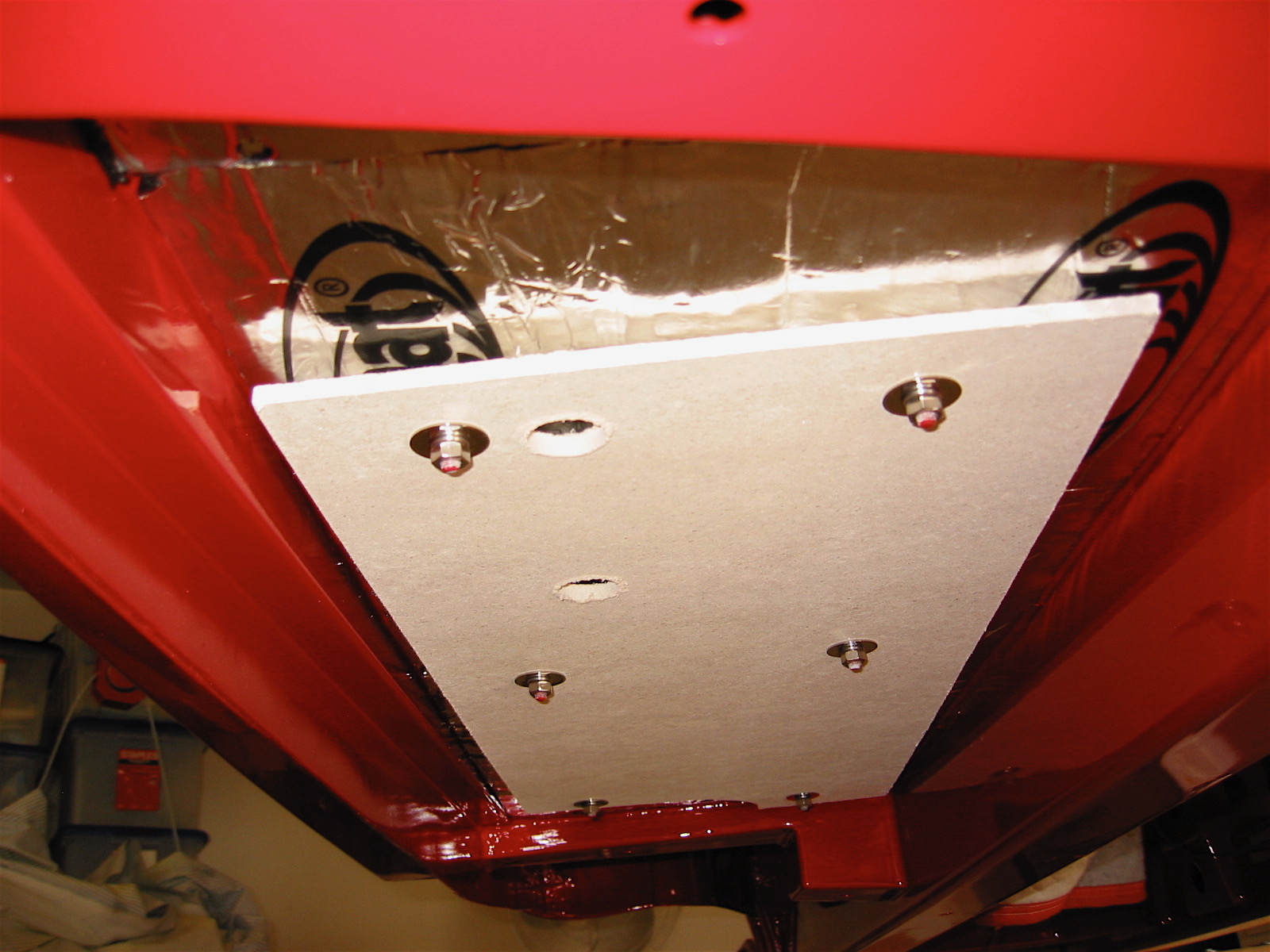
Muffler Insulation Panel
I then moved on to the interior of the firewall and to the driver’s side footwell. I used an awl to find the holes in the interior floor and to make holes through the dynamat material.
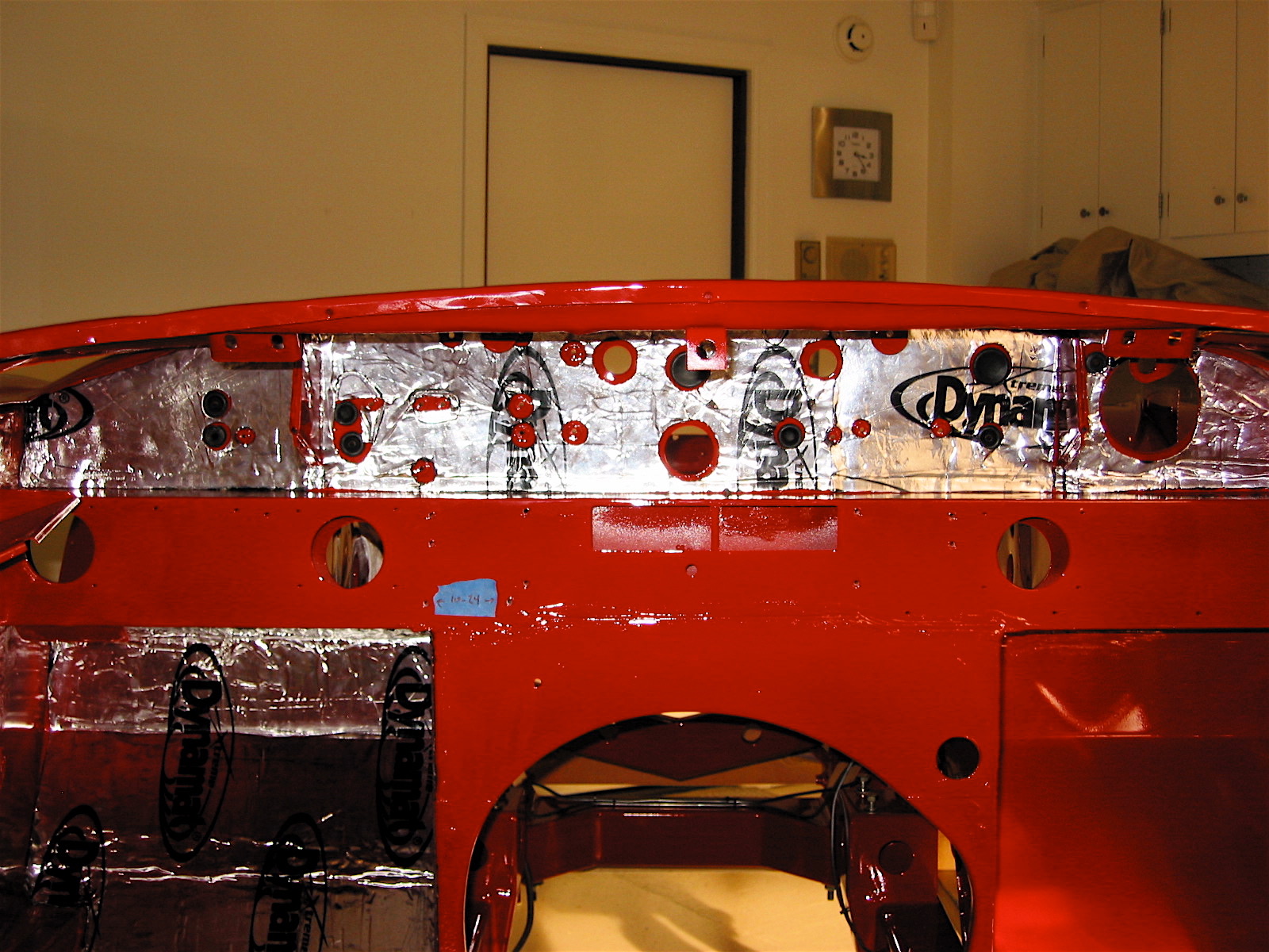
Dynamat Extreme 2
Dynamat Extreme 3
Next I fastened the insulation panels in the engine compartment.
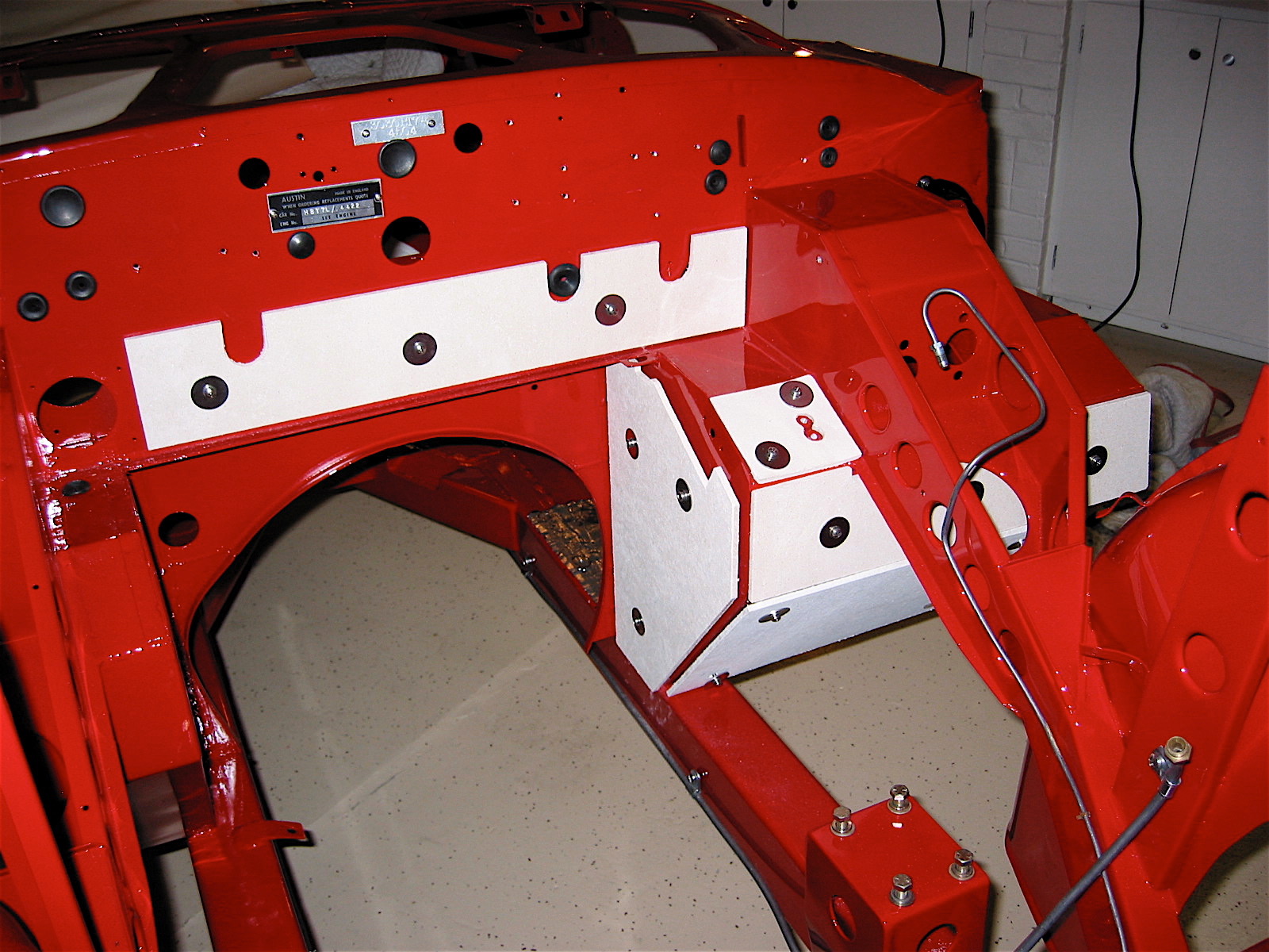
Engine Insualtion panels