August 26, 2003
Wiring
Wiring Harness – Received the new wiring harness from British Wiring Inc. We ordered the main harness, horn wiring that we probably won’t need, light pigtails and the stator tube wiring. Everything looked good. Also ordered a special pliers for pushing the wiring bullet connectors into the rubber joints which will prove to be a real time saver.
After taking the harness through the firewall, the major components were separated to go down the two sides of the car.
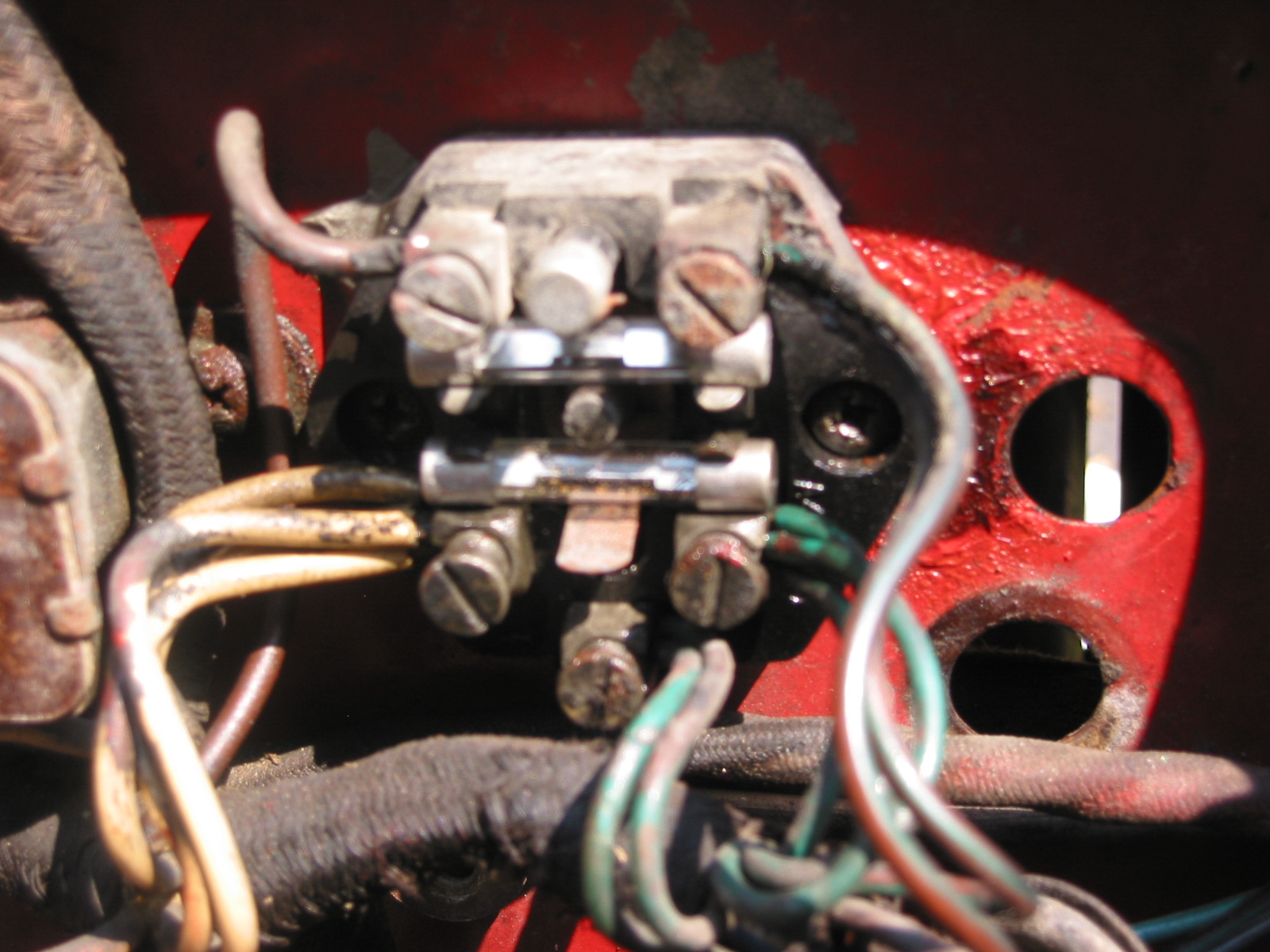
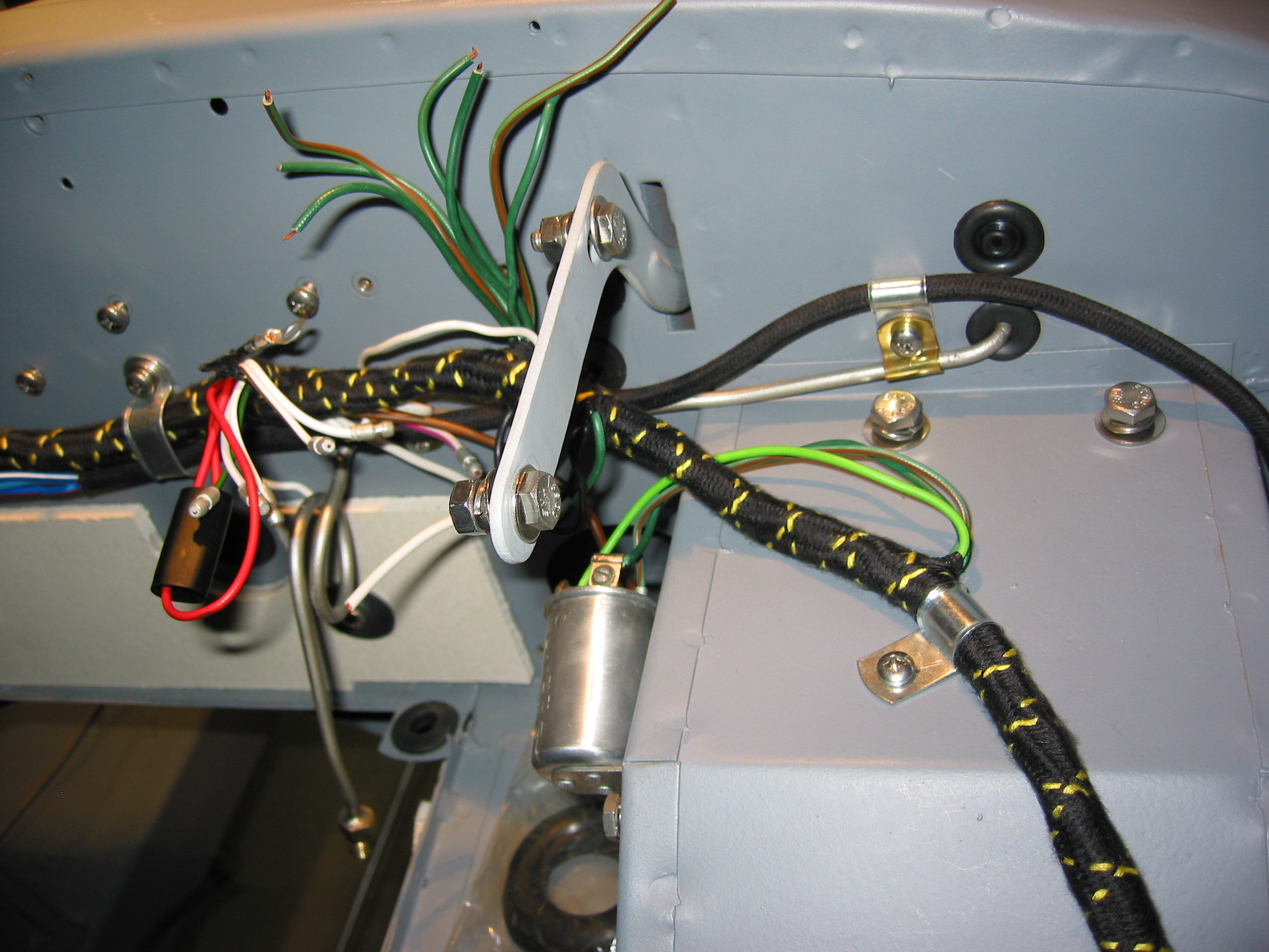
Flasher – First connected the three wires to the flasher – green, light green, and green/brown.
Wiper Harness – Then connected the wiper harness with connectors and fed it through the firewall – black, black/green, and green.
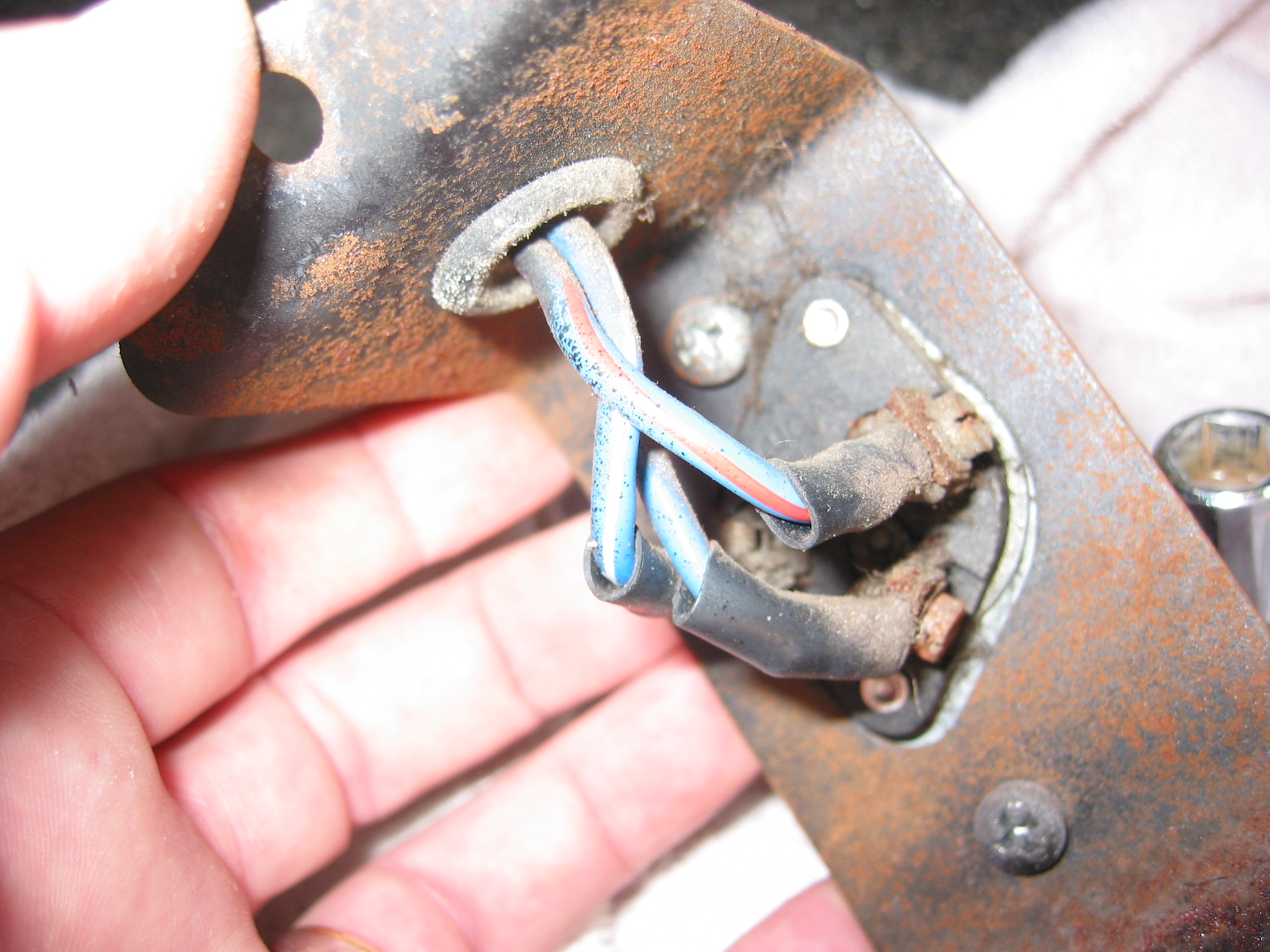
Dimmer Switch – The wires for the dimmer switch were then connected and fed through the top of the footbox and connected to the switch – blue/red, light blue, and blue/white.
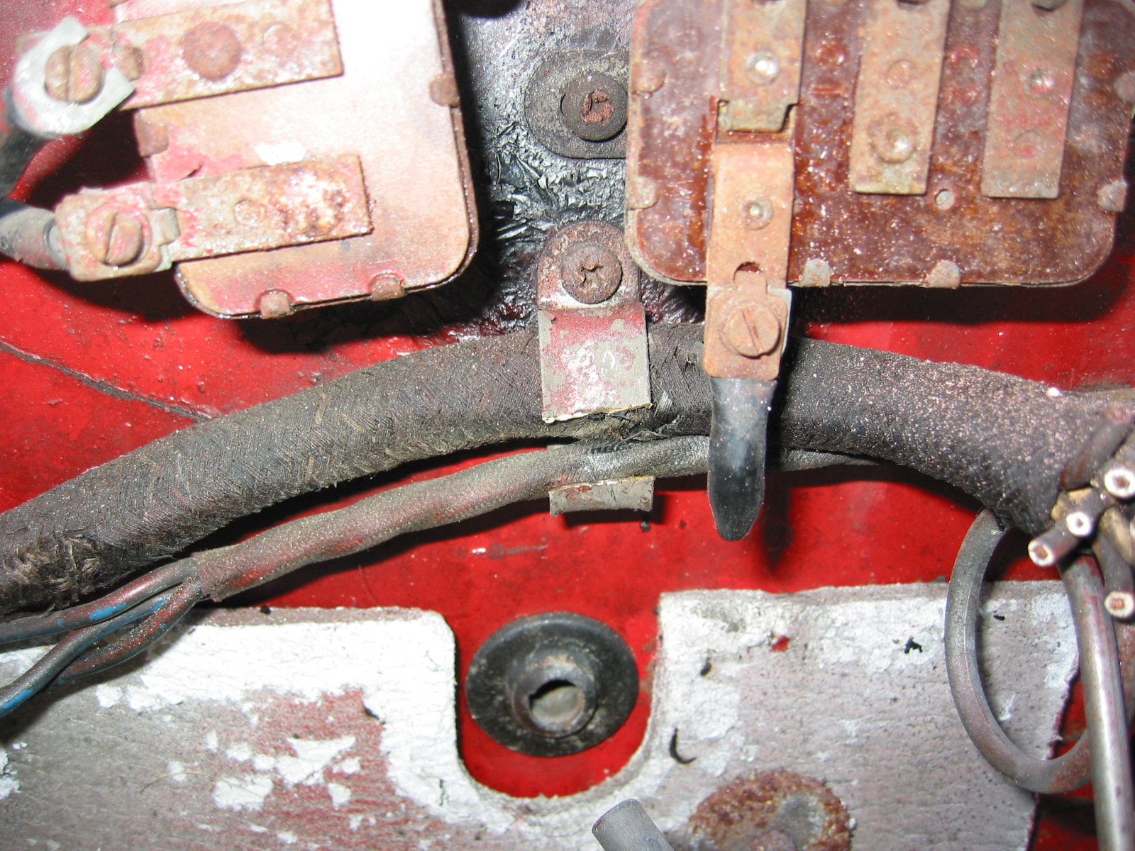
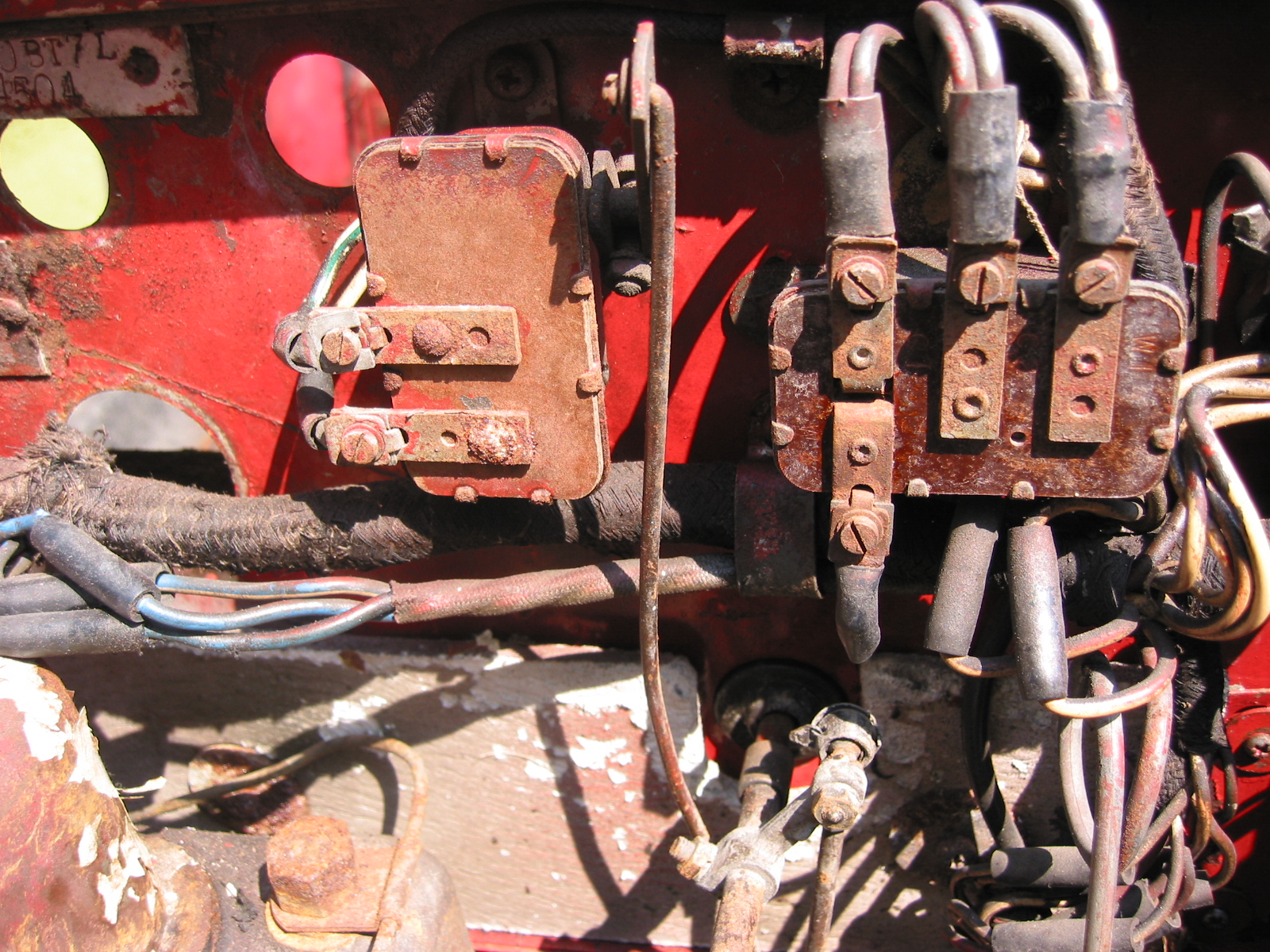
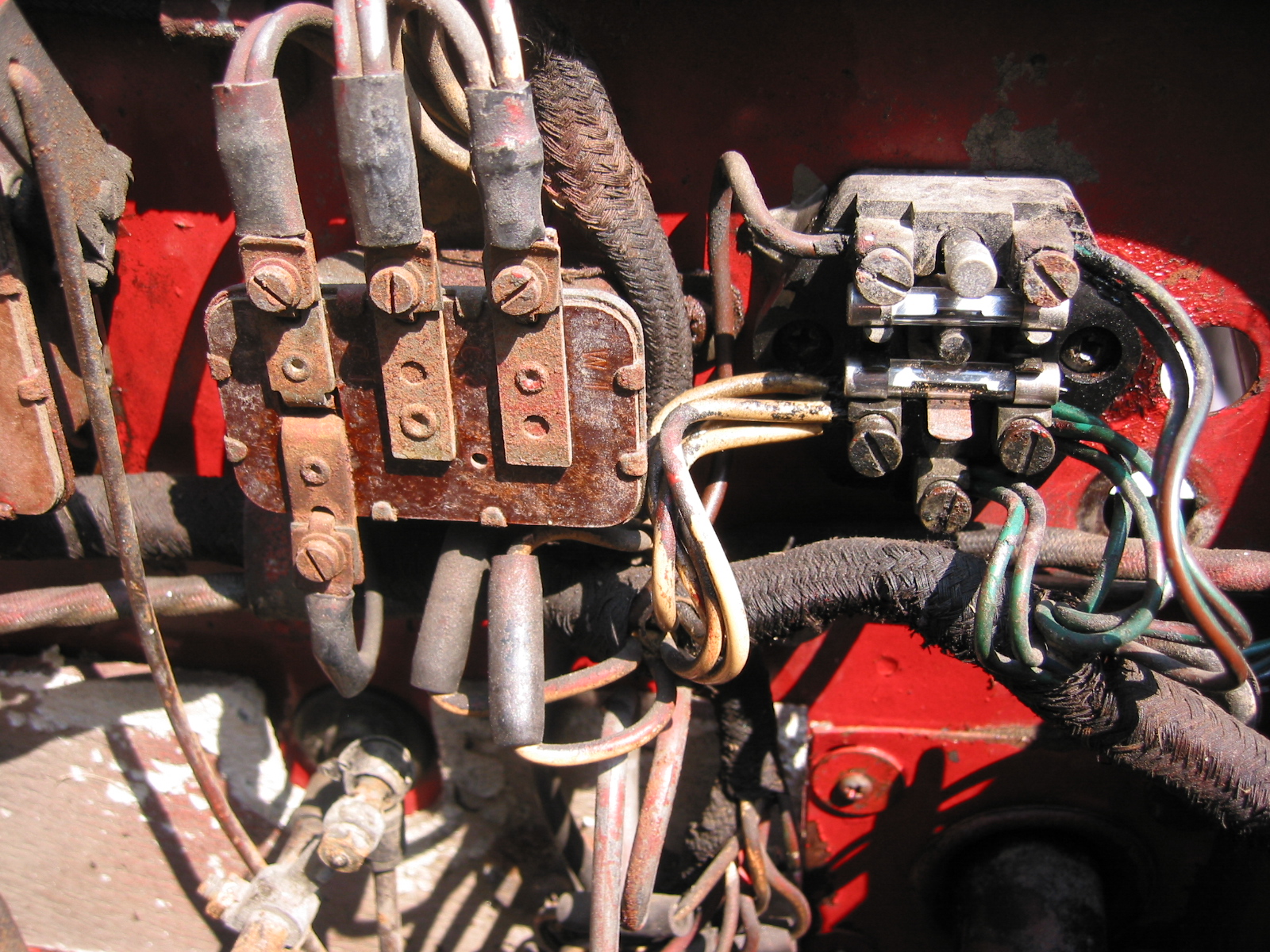
Fuse Panel – Wiring was then connected from the harness to the fuse box. Three white wires to the lower left terminal; one heavy brown wire to the top left terminal; two brown/green wires to the upper right terminal; and five green wires to the lower right terminals.
Throttle Switch – The white and white/purple wires intended for the throttle switch will not be used so rubber connectors were placed on the ends to avoid contact with metal. The wires were tucked below the fuse box.
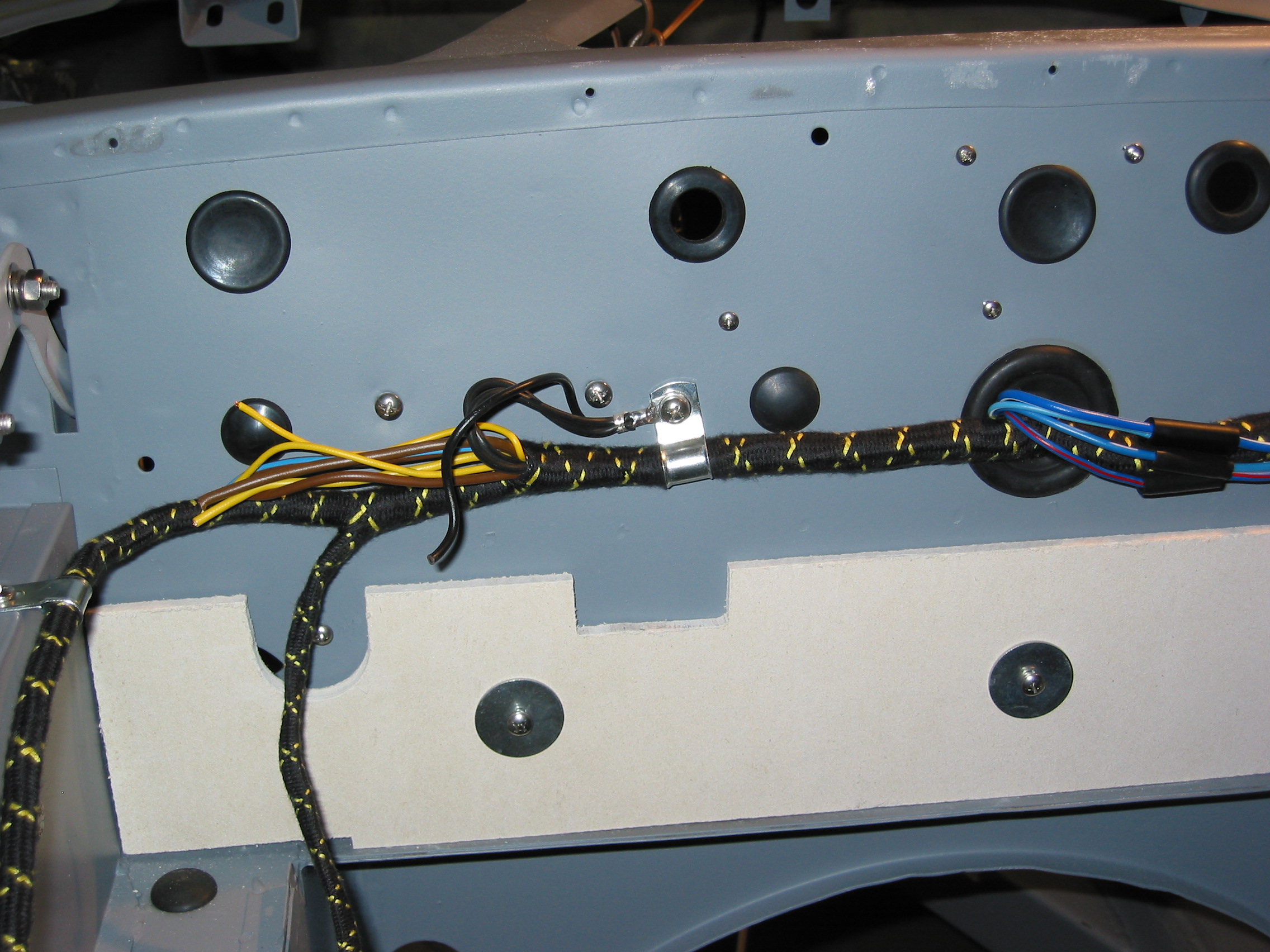
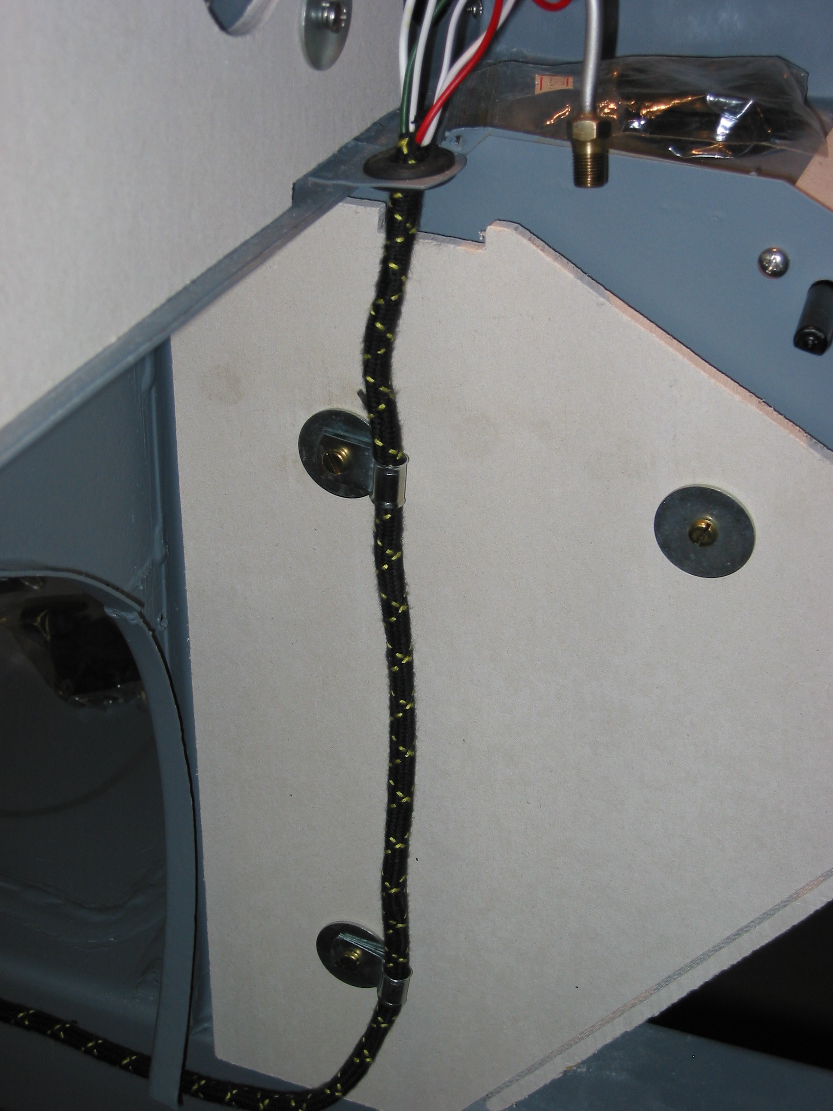
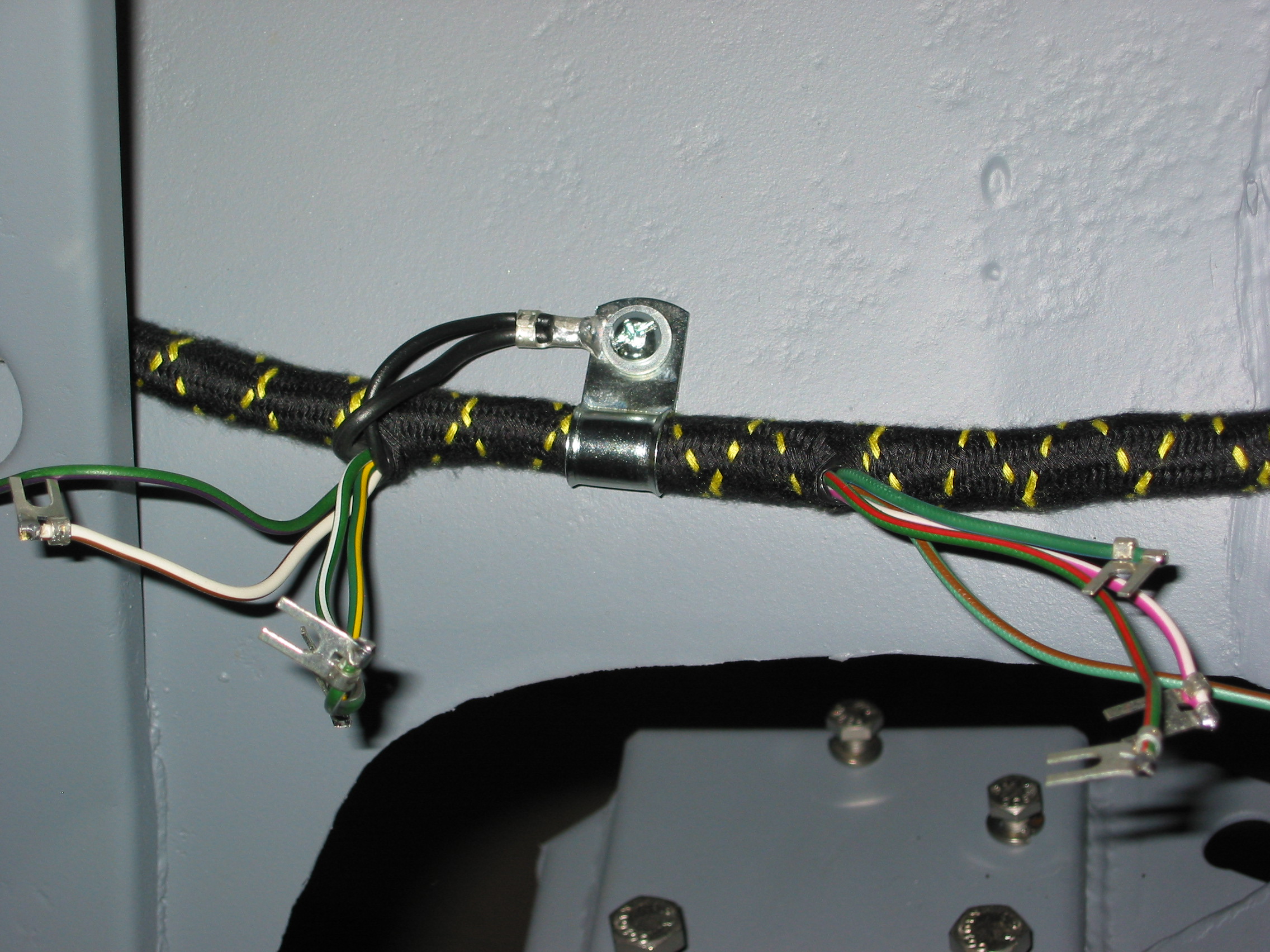
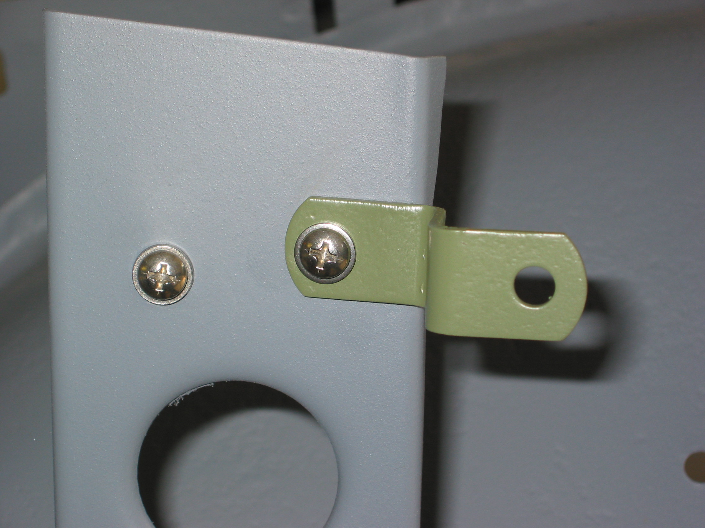
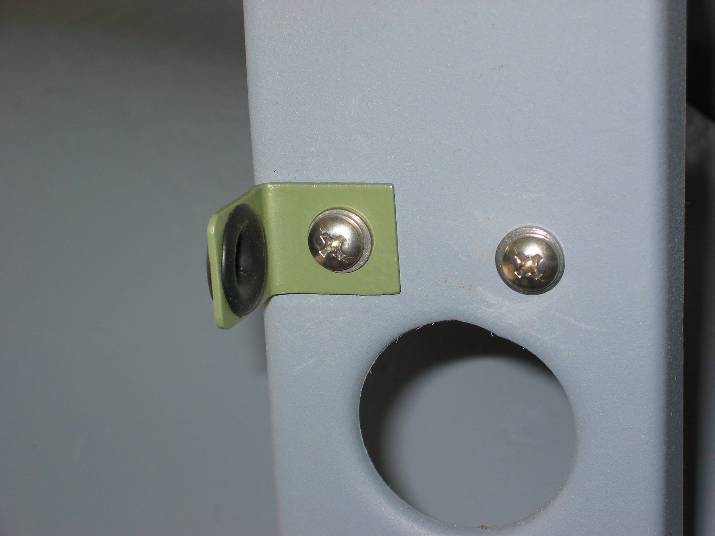
Boot Harness Extension – Six wires were then connected from the firewall harness to the harness that goes to the fuel pump and boot for the lights. The harness runs down the footbox insulation panel with two clips. The harness was clipped to the master cylinder box and then taken through the welded clip on the wheel well.
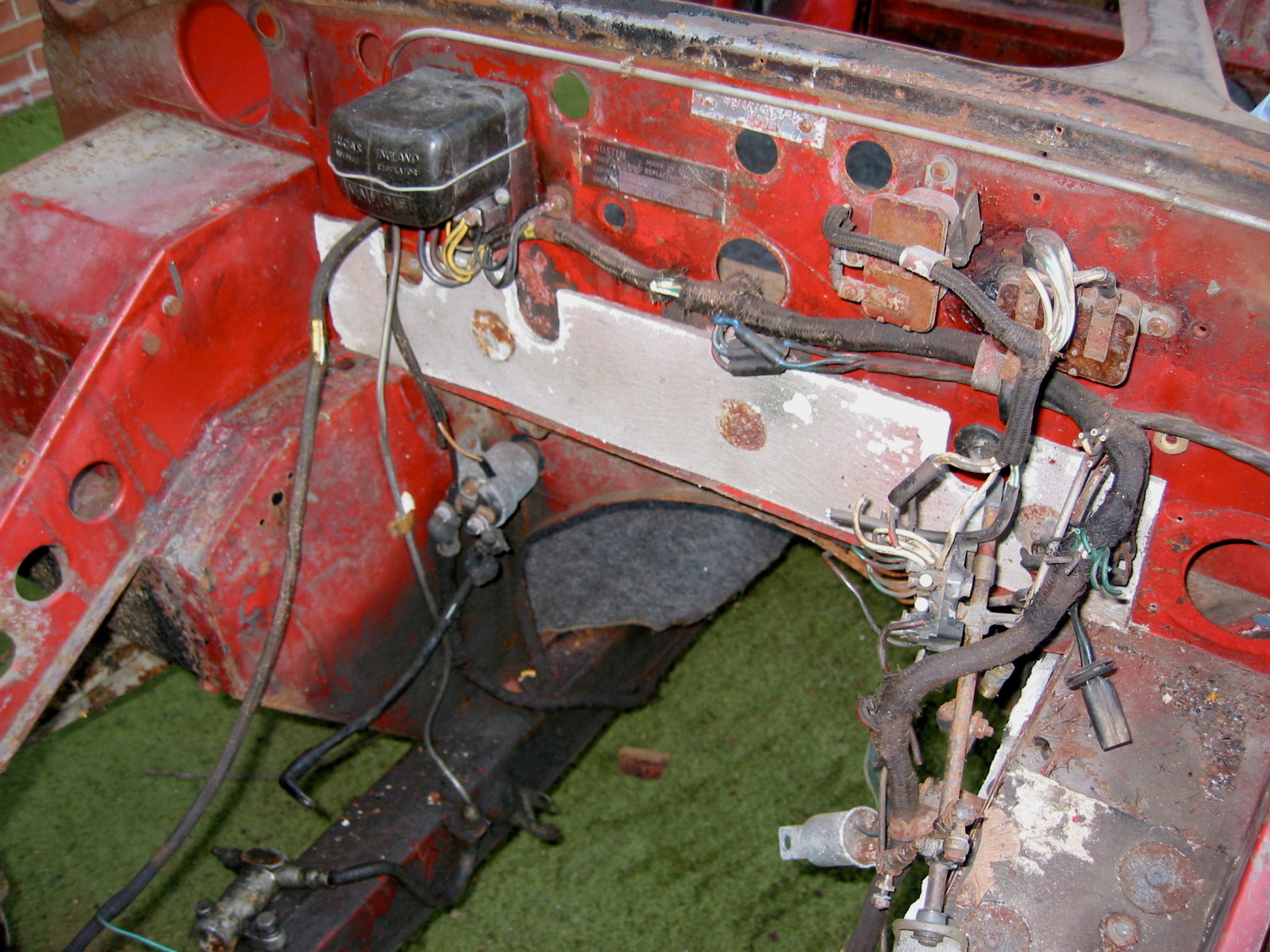
Flasher Relay Box – Wires on the left side will then be connected to the flasher relay box including a black ground wire at the base of the box.
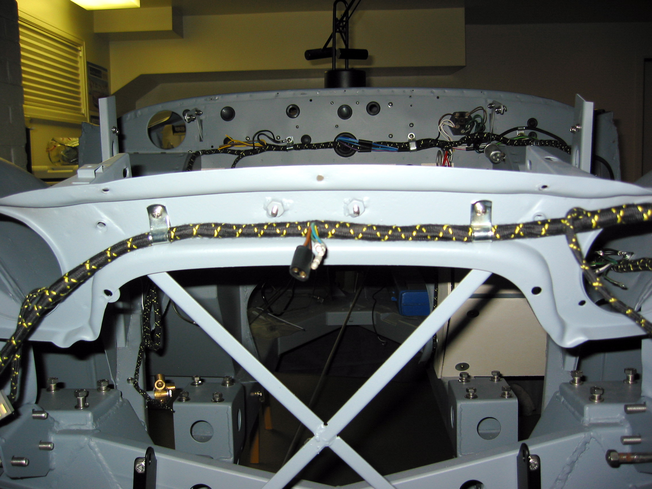
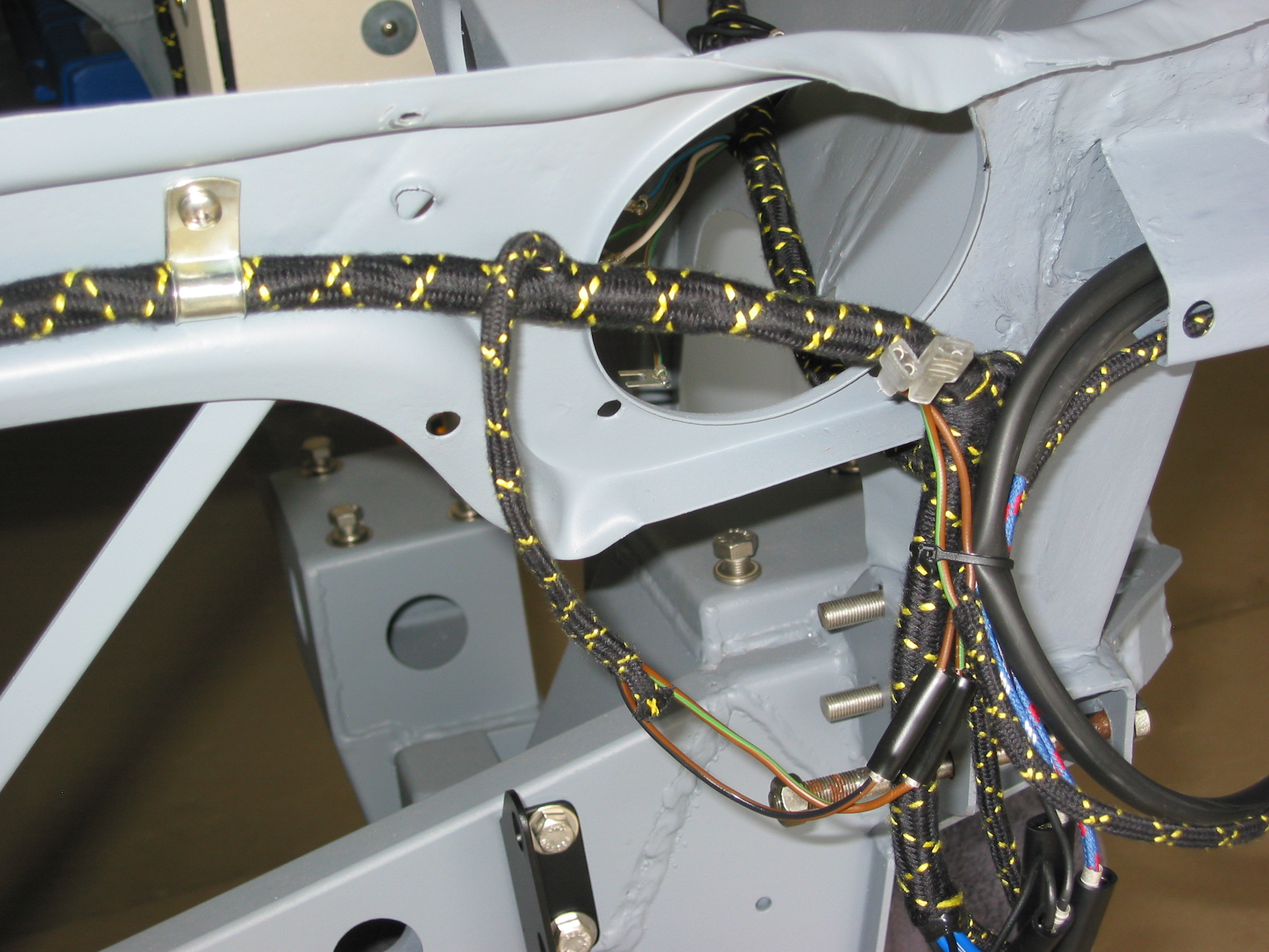
Lights and Horns – The wires were routed to the front of the superstructure for the lights and the horns.
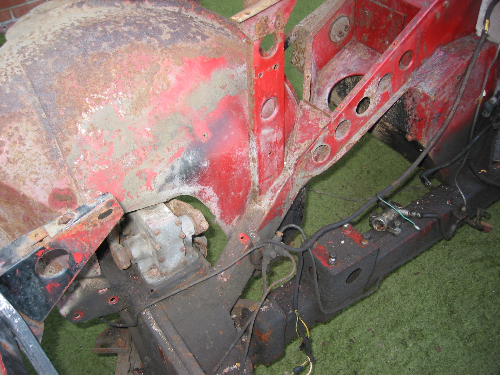
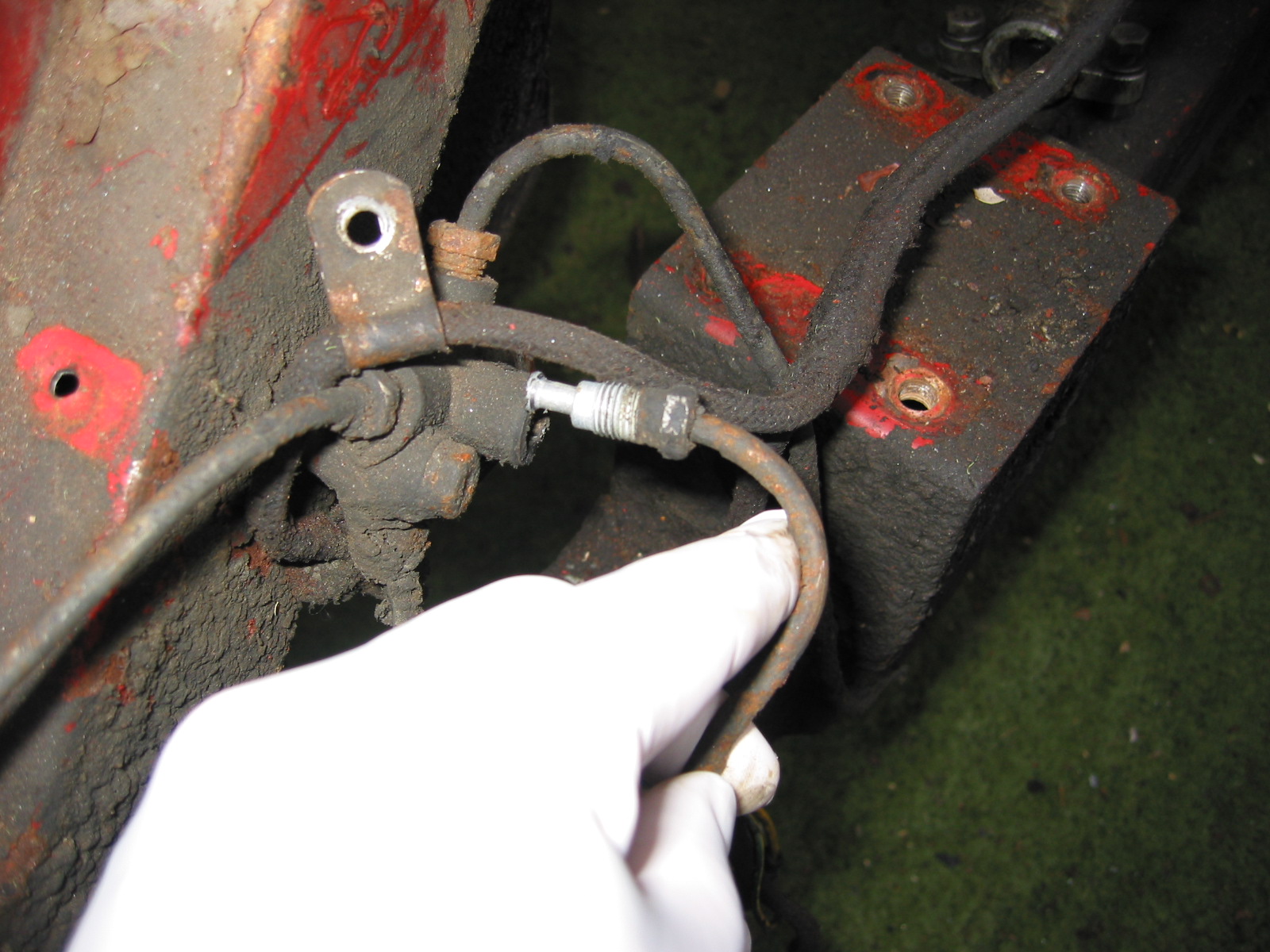
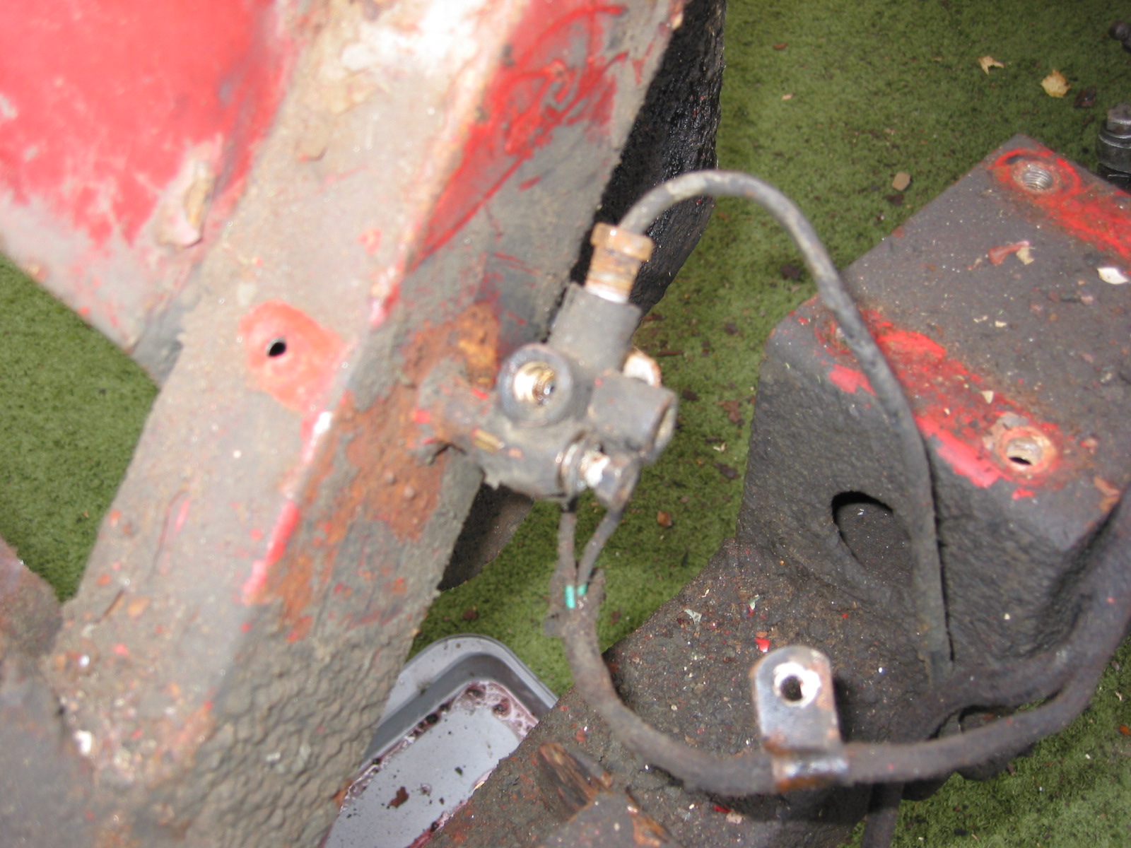
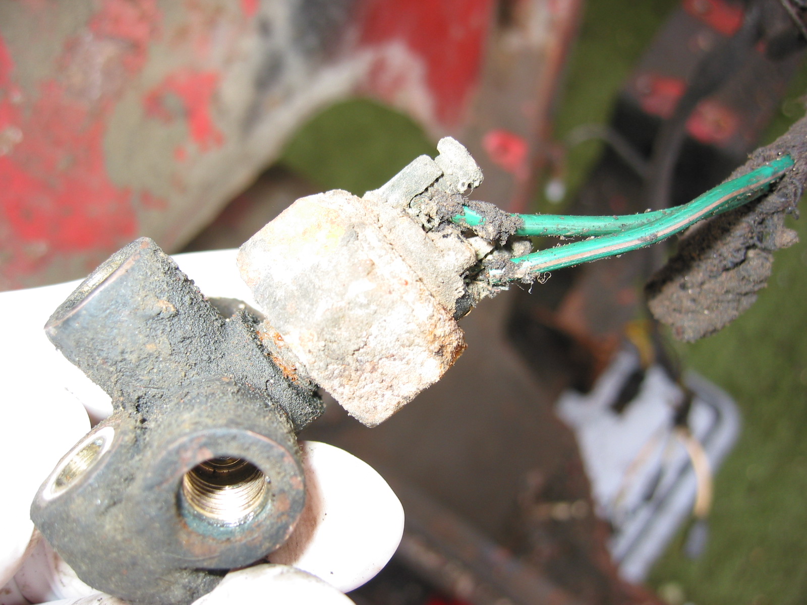
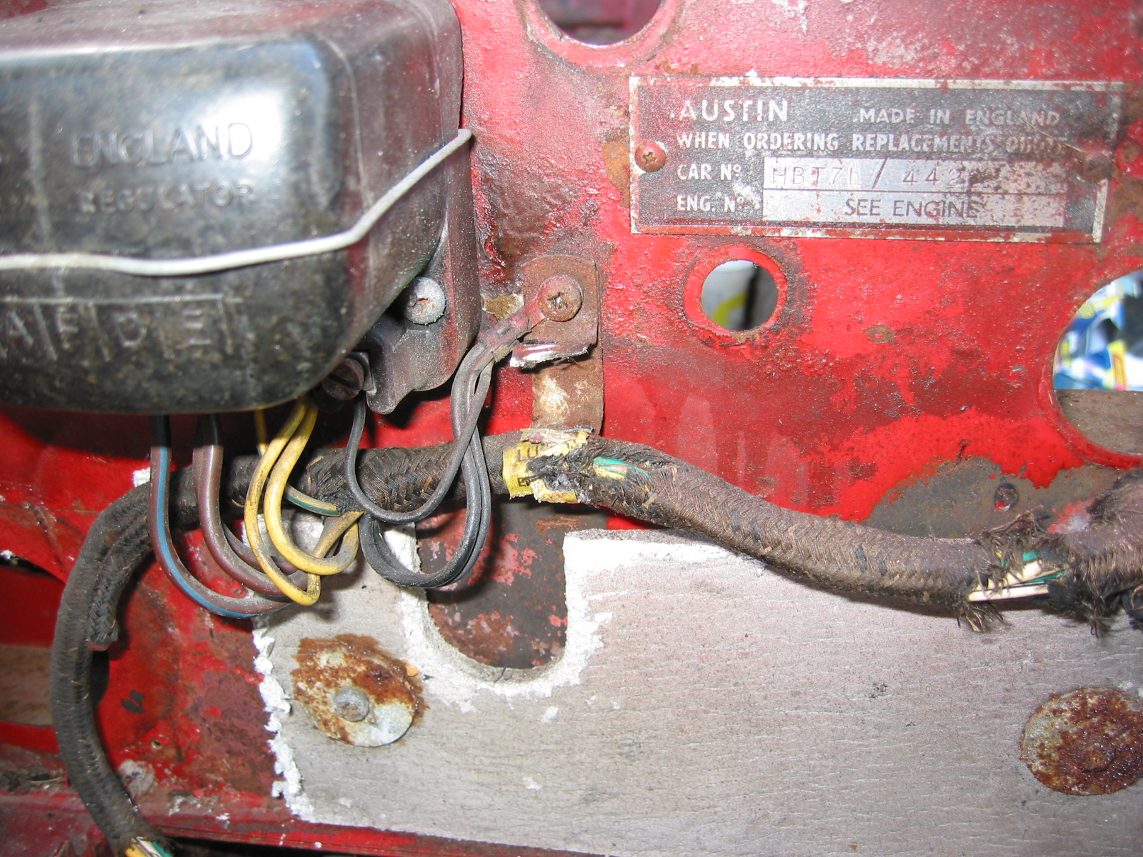
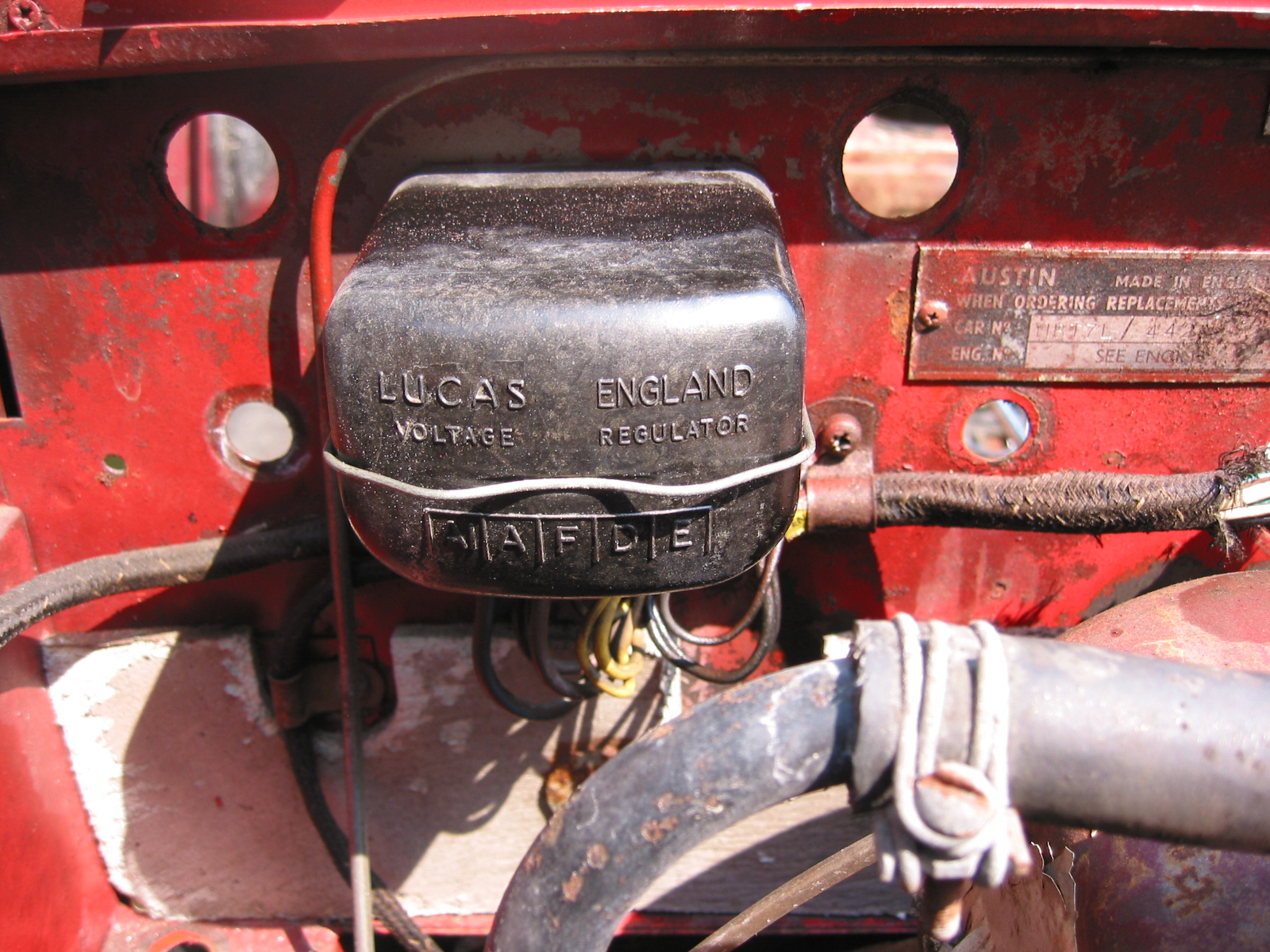
Voltage Regulator Box and Brake Light Switch – The harness was also routed down the right side, by the voltage box and down the right side to the brake light switch.
Wiring 3
Wiring 1

Wiring Fuse Block 2
Wiring 6
Wiring 8
Wiring 9
Wiring 12
September 9, 2003
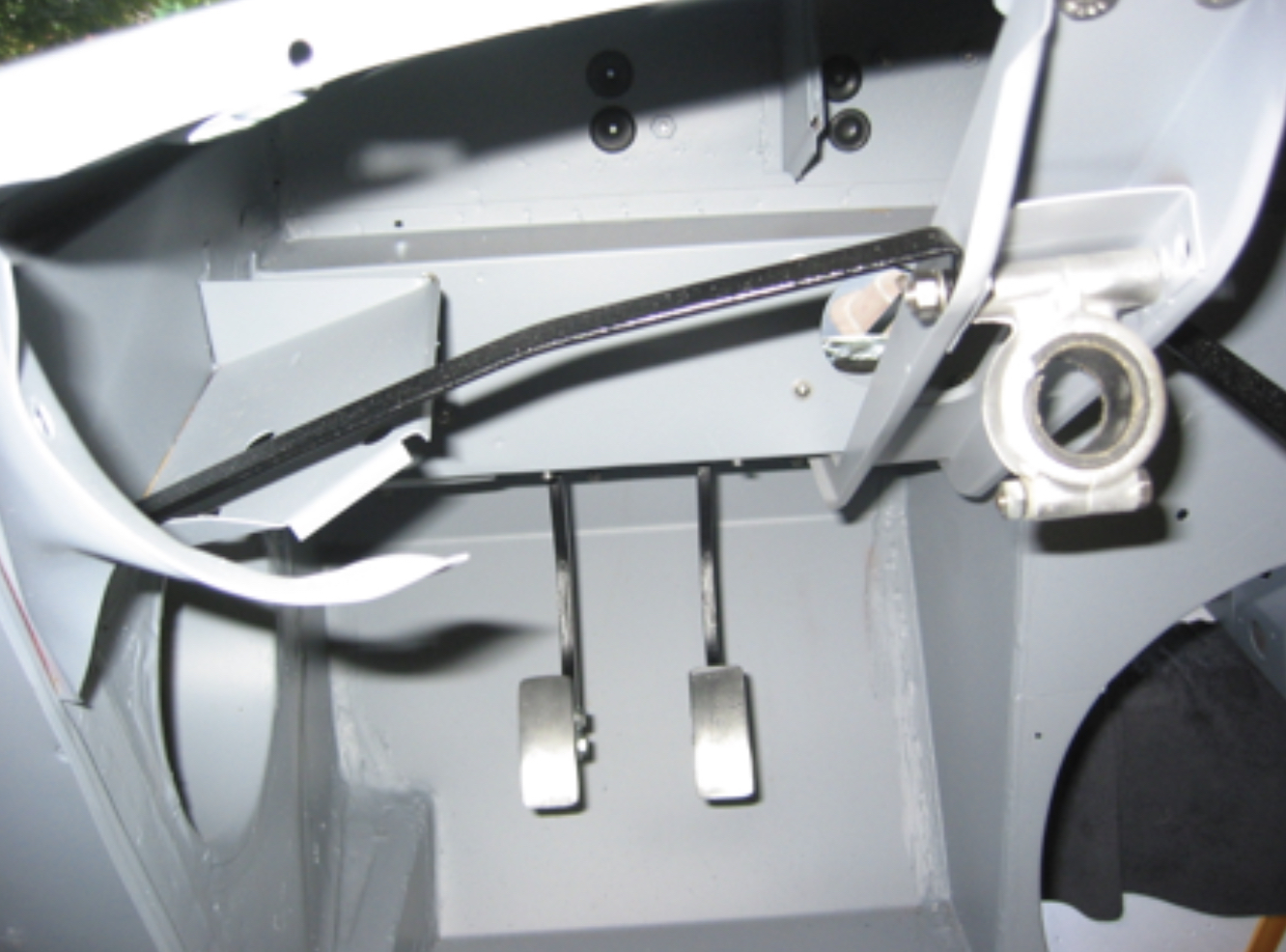
Heater Vent Doors – Installed the left and right heater outlet vent door assemblies.

Air Vents 1

Air Vents 2
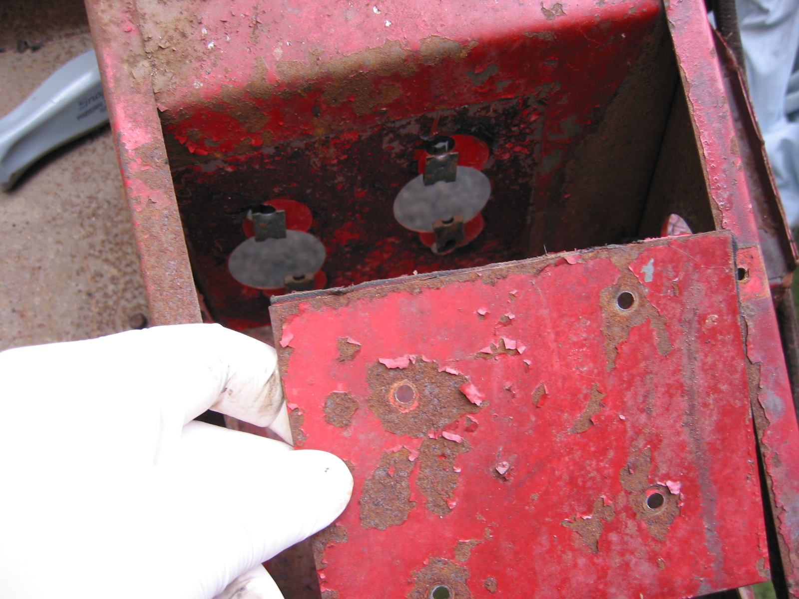
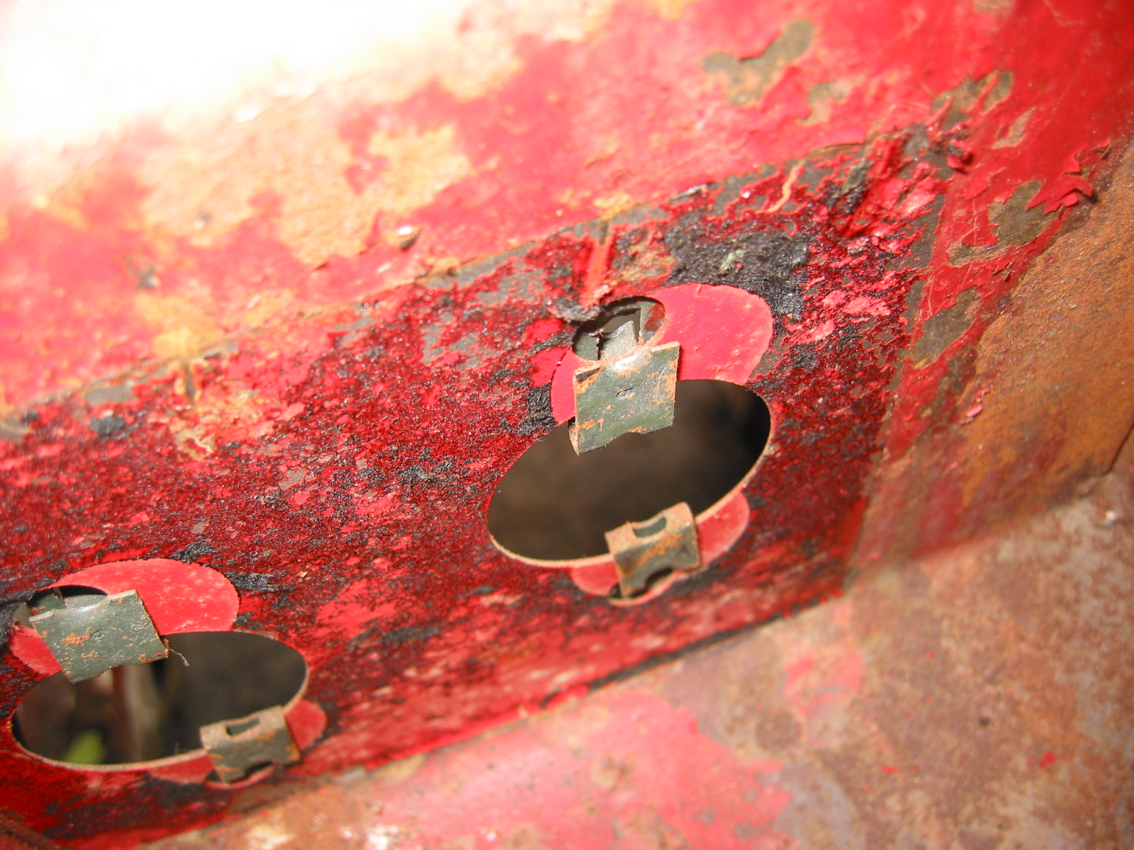
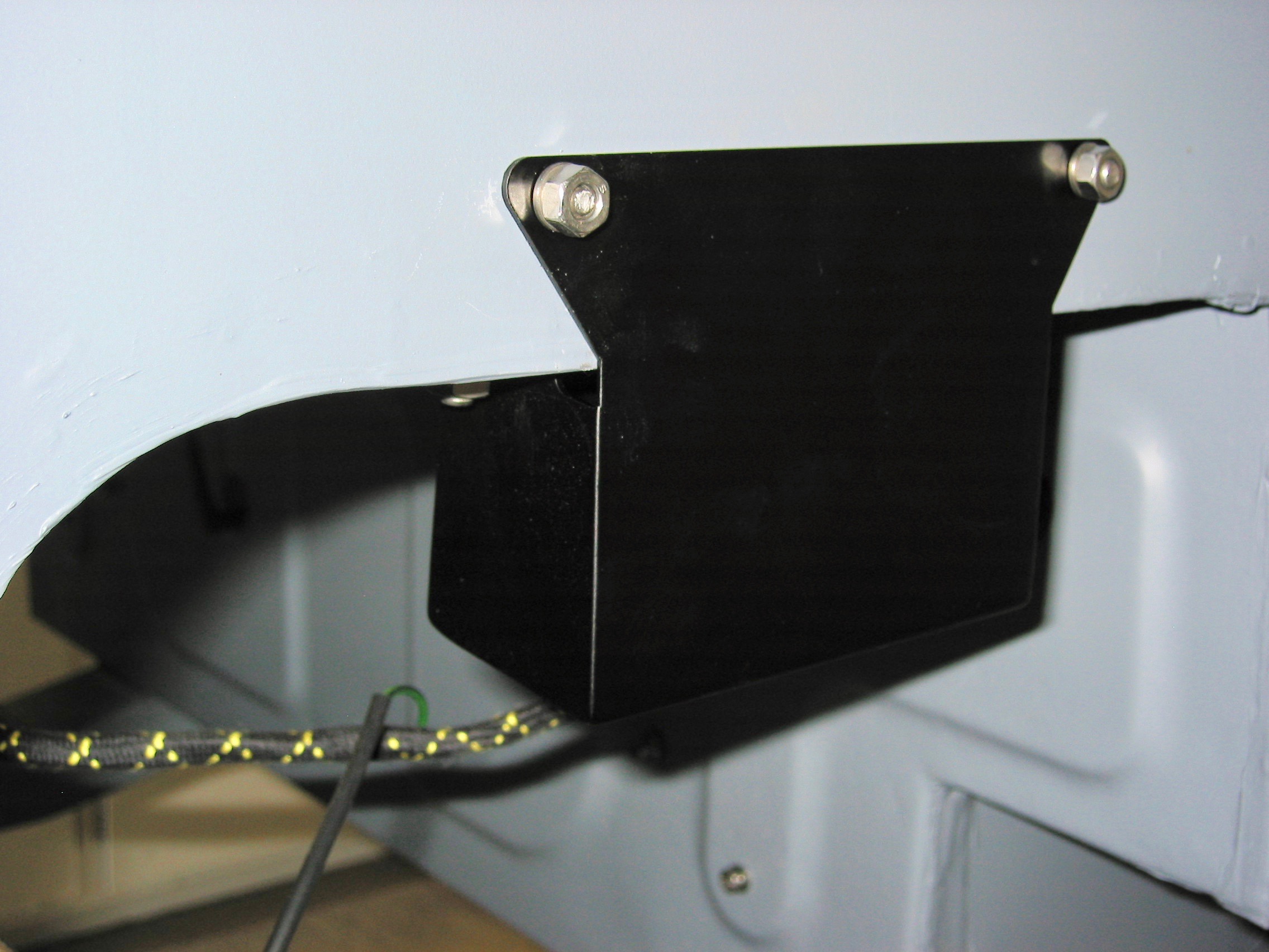
Bump Boxes – Installed painted bump boxes. Secured threaded horn mounting plates.
Bump Box Painted 1
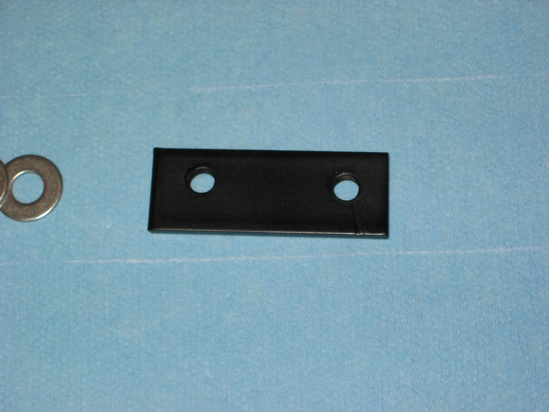
Steering column bracket tapped plate
Parcel Tray and Fascia Brackets – Installed parcel tray support bracket and fascia support brace.
Parcel Tray Brace
Fascia Brace
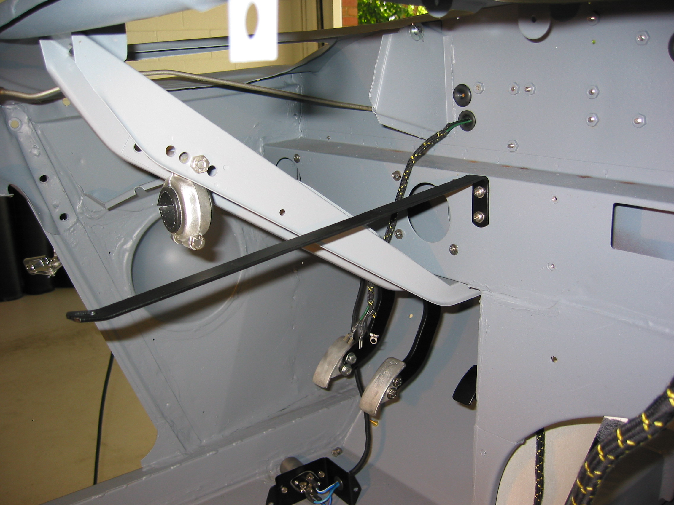
Steering Column Steady Bracket – Installed steering column steady bracket, but unclear about which windscreen post hole it should mount to – will check it out later.
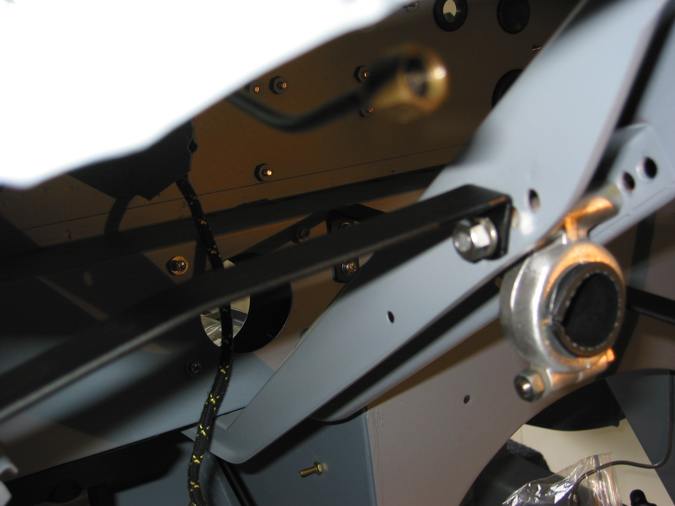
Steering support Brace
Steering Column Steady Bracket 2
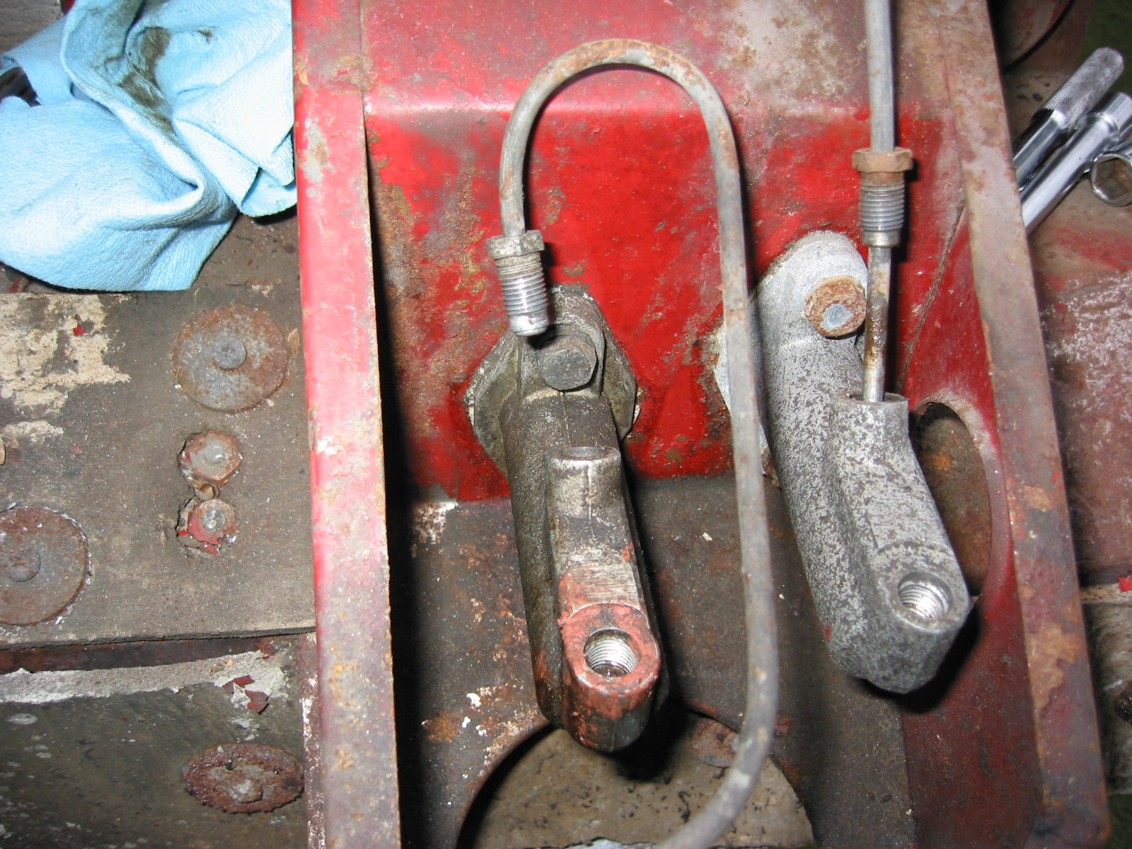
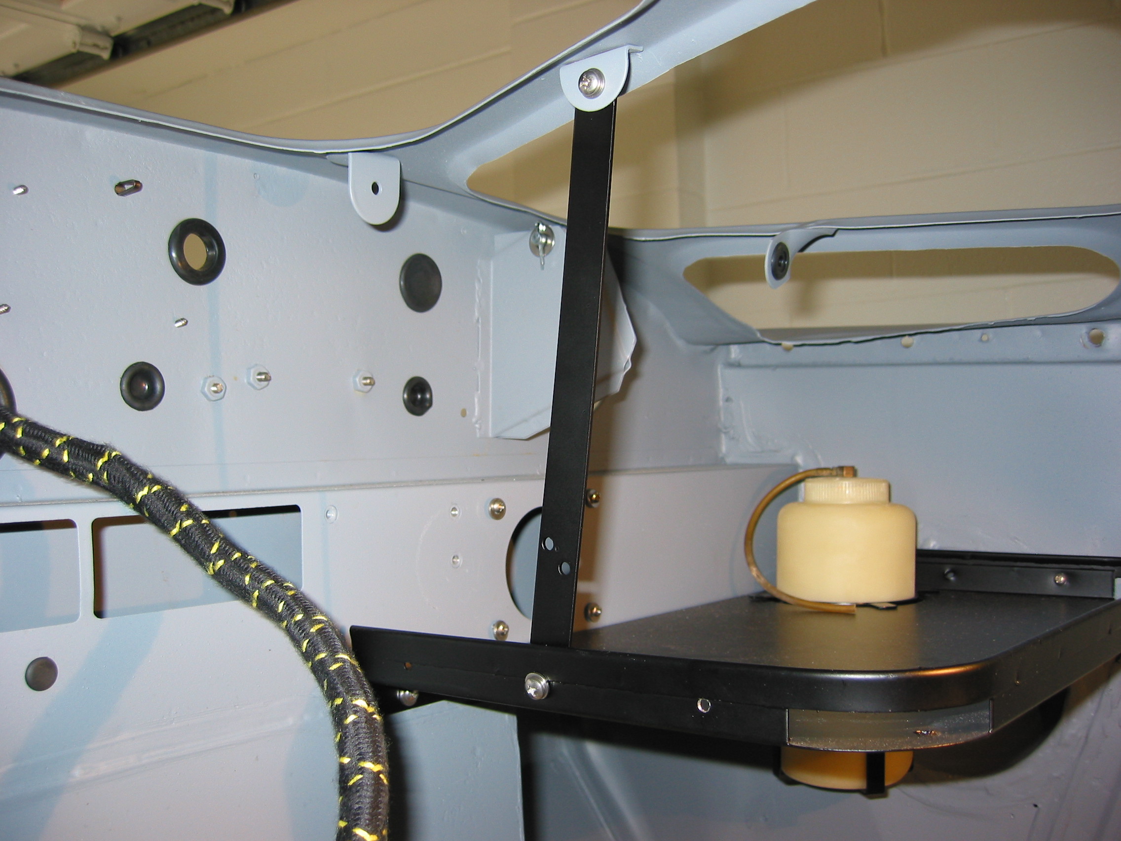
Bonnet Prop Rod and Brake Reservoir Brackets – Installed bonnet prop rod bracket, pivot, and the brake reservoir mounting bracket.
Brake Reservoir Bracket
Bonnet Rod Bracket
Bonnet safety catch and prop rod bracket
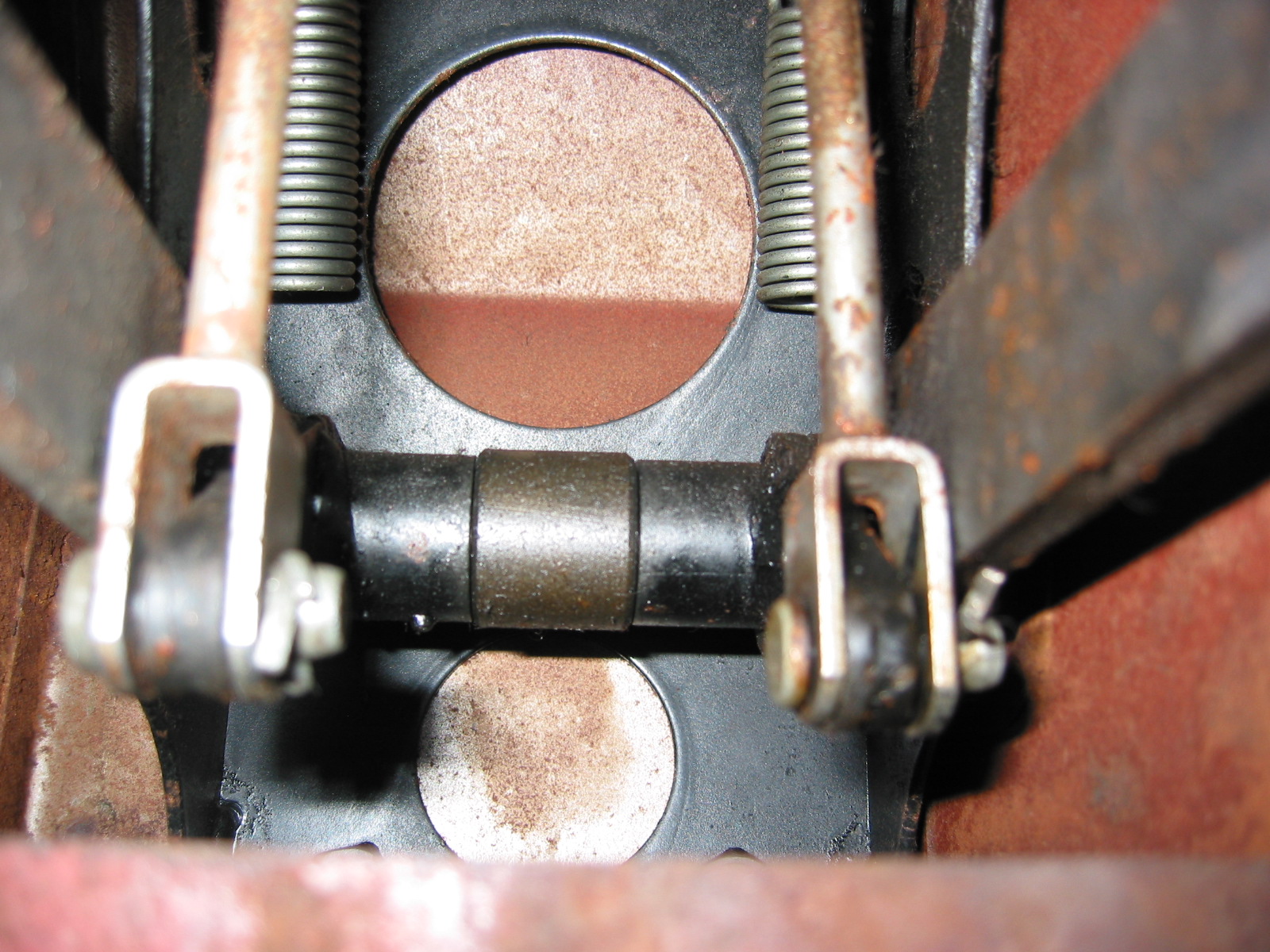
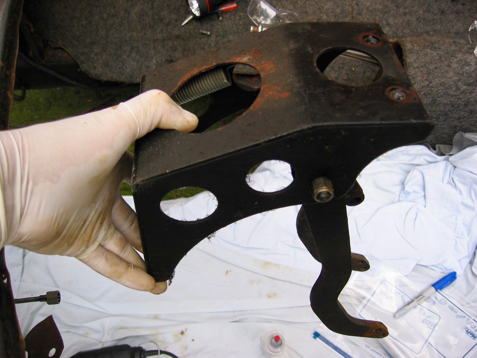
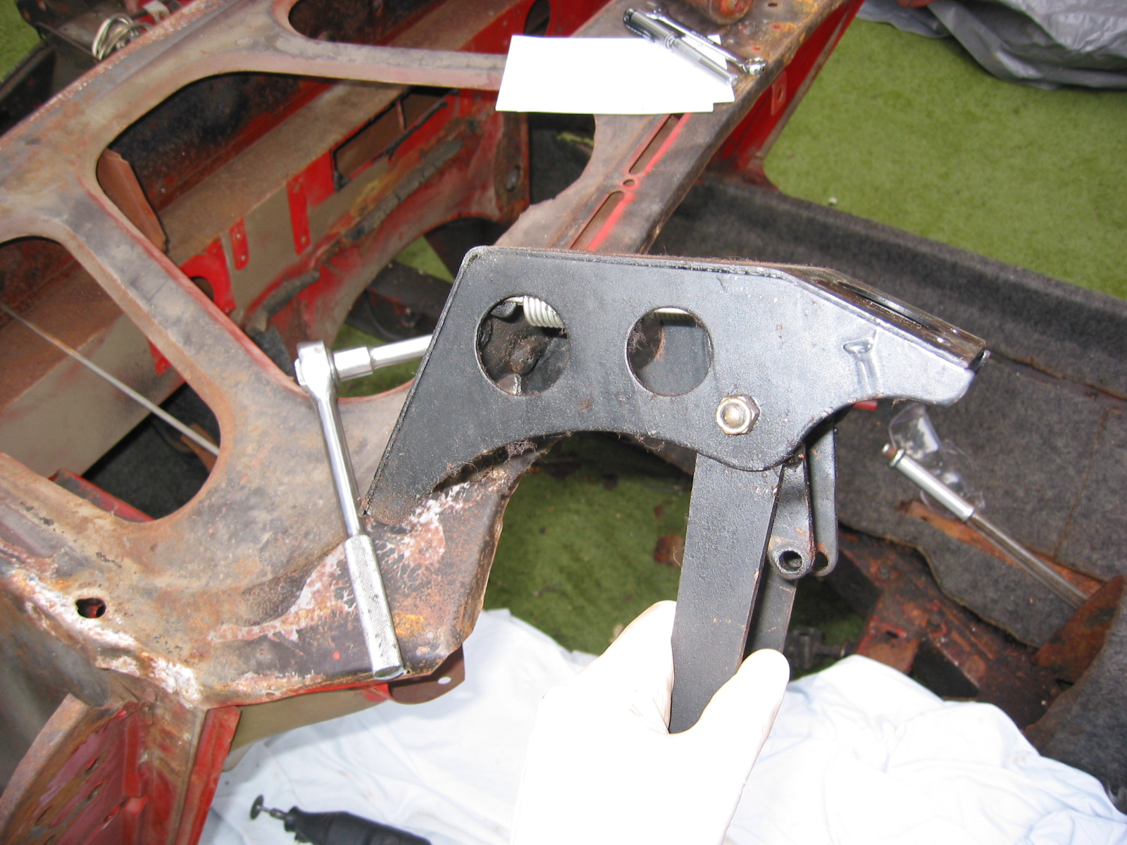
Bonnet Latch Bracket and Release Mechanism – Assembled and installed the bonnet latch/release mechanism.
Bonnet Catch painted 4
Bonnet Catch painted 3
Bonnet Catch painted 2
September 13, 2003
Wiring Continued
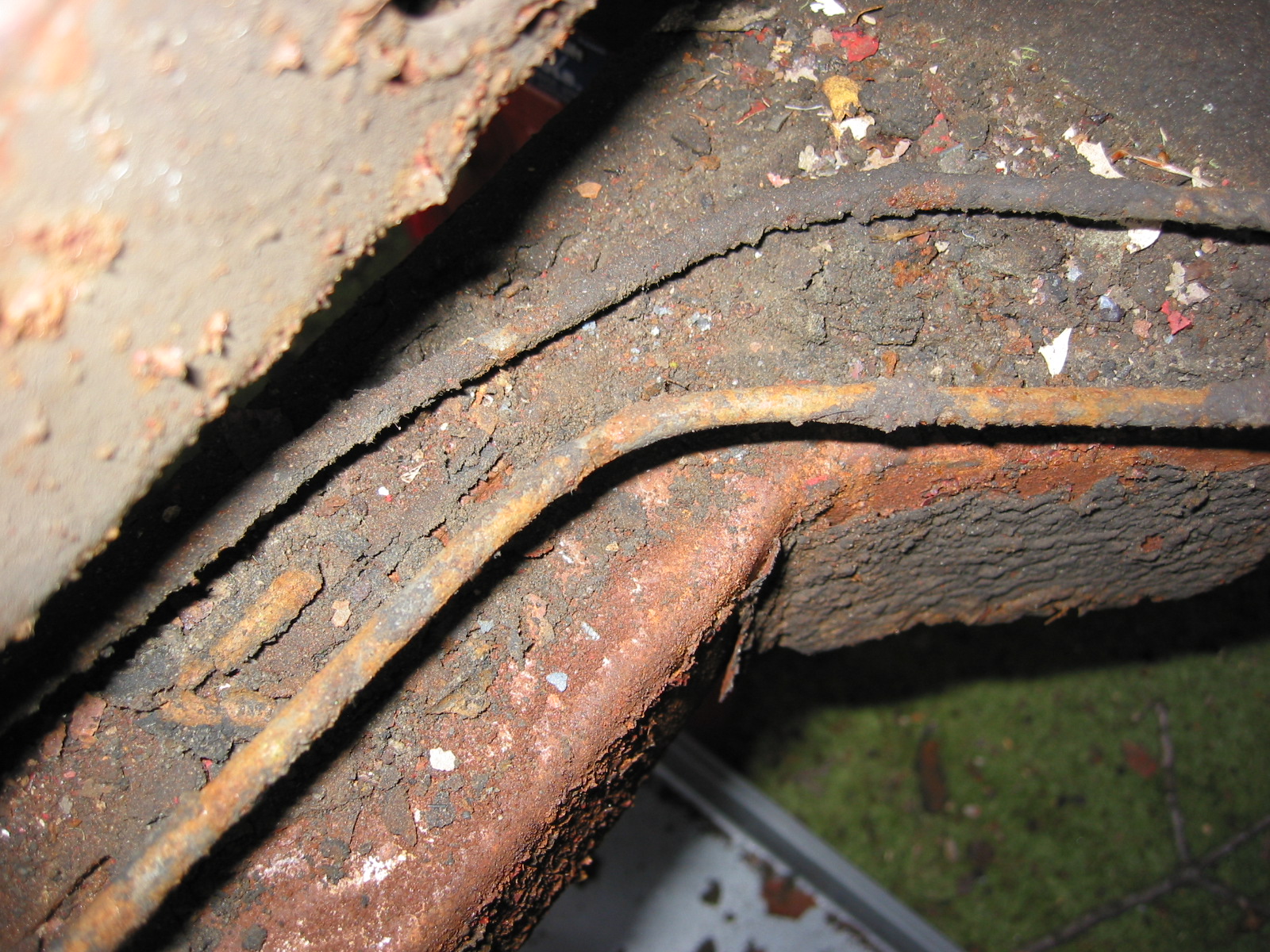
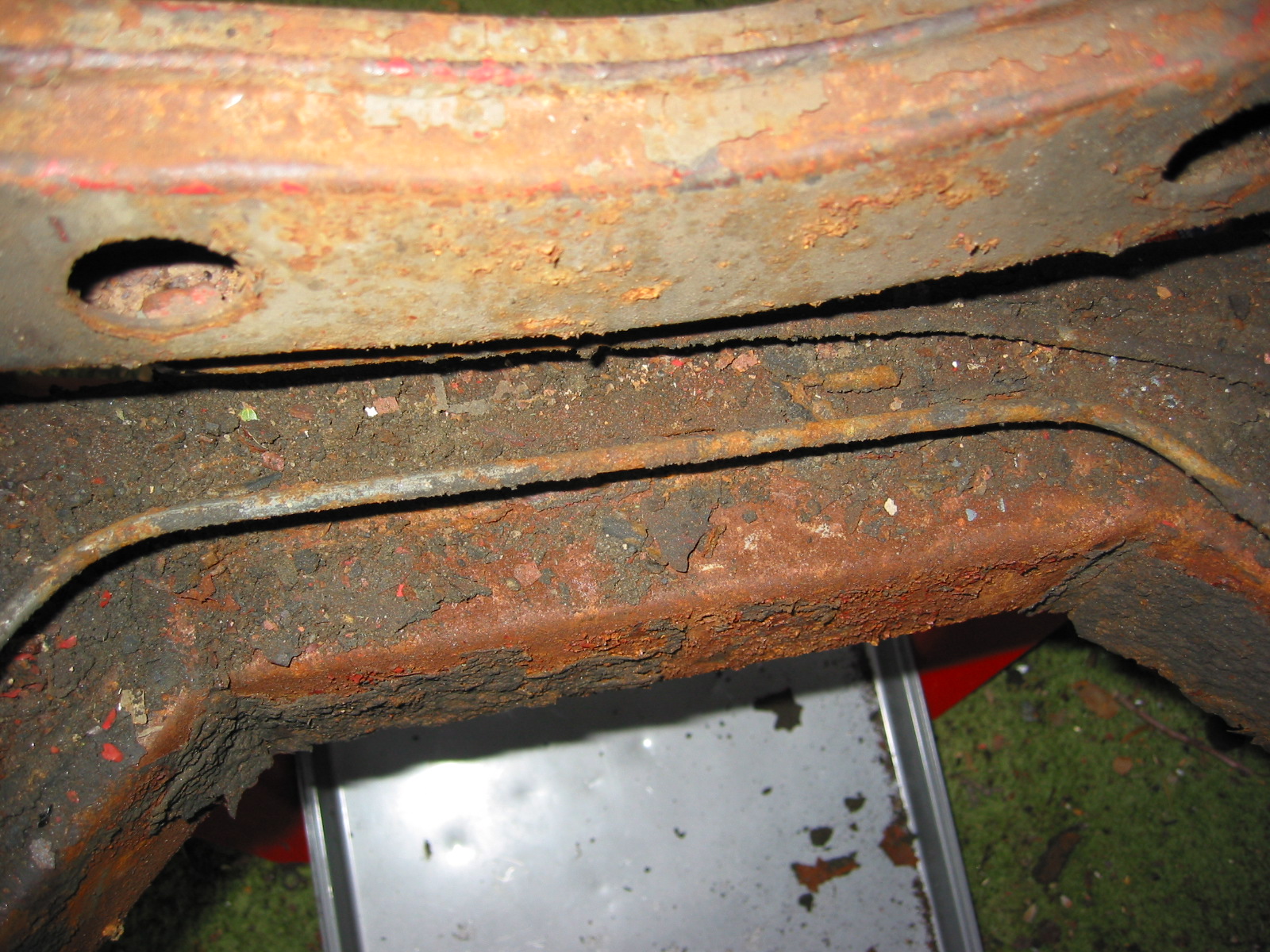
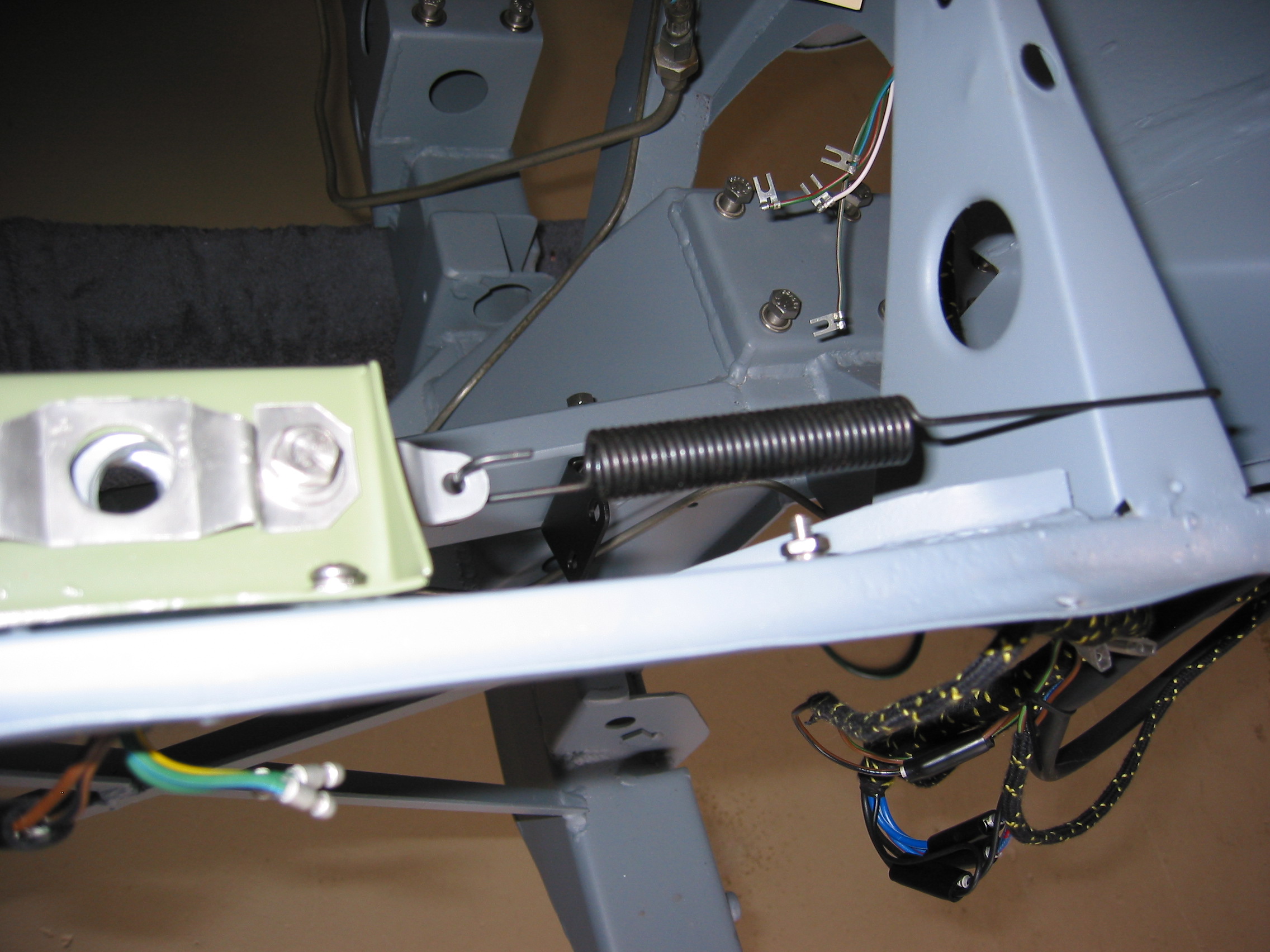
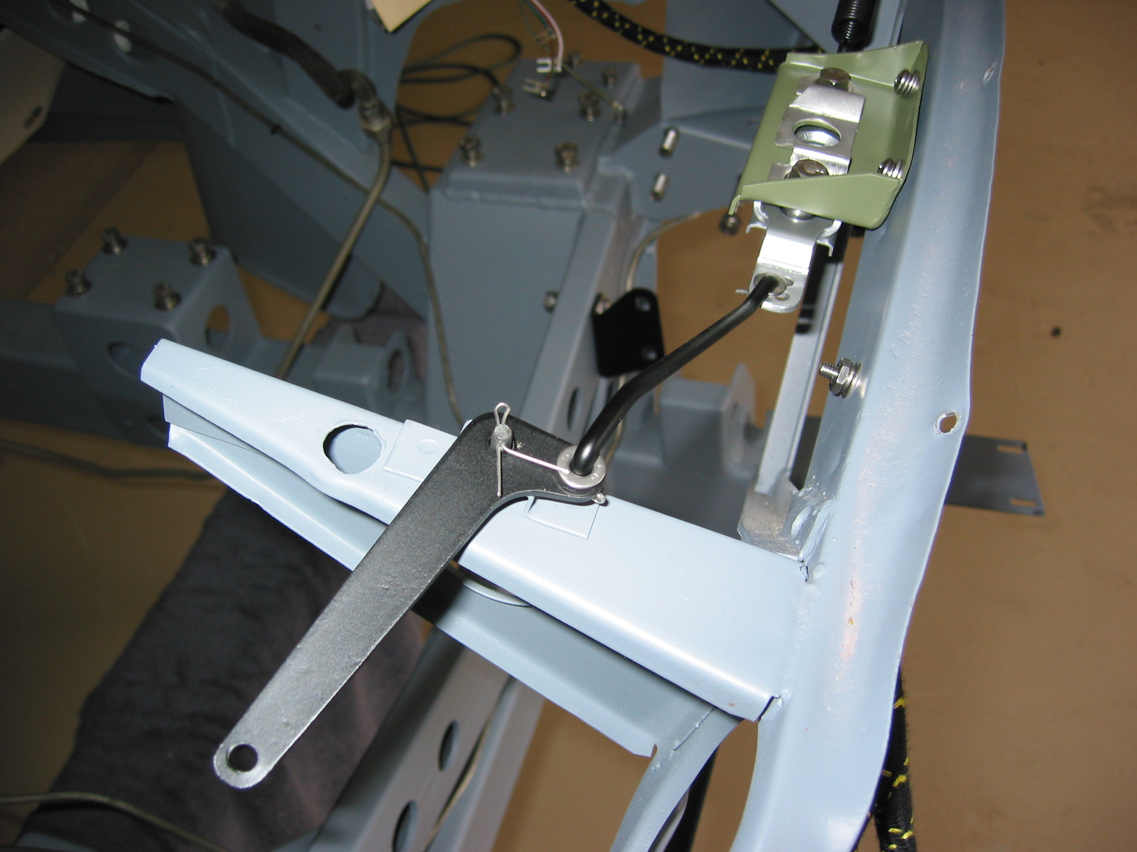
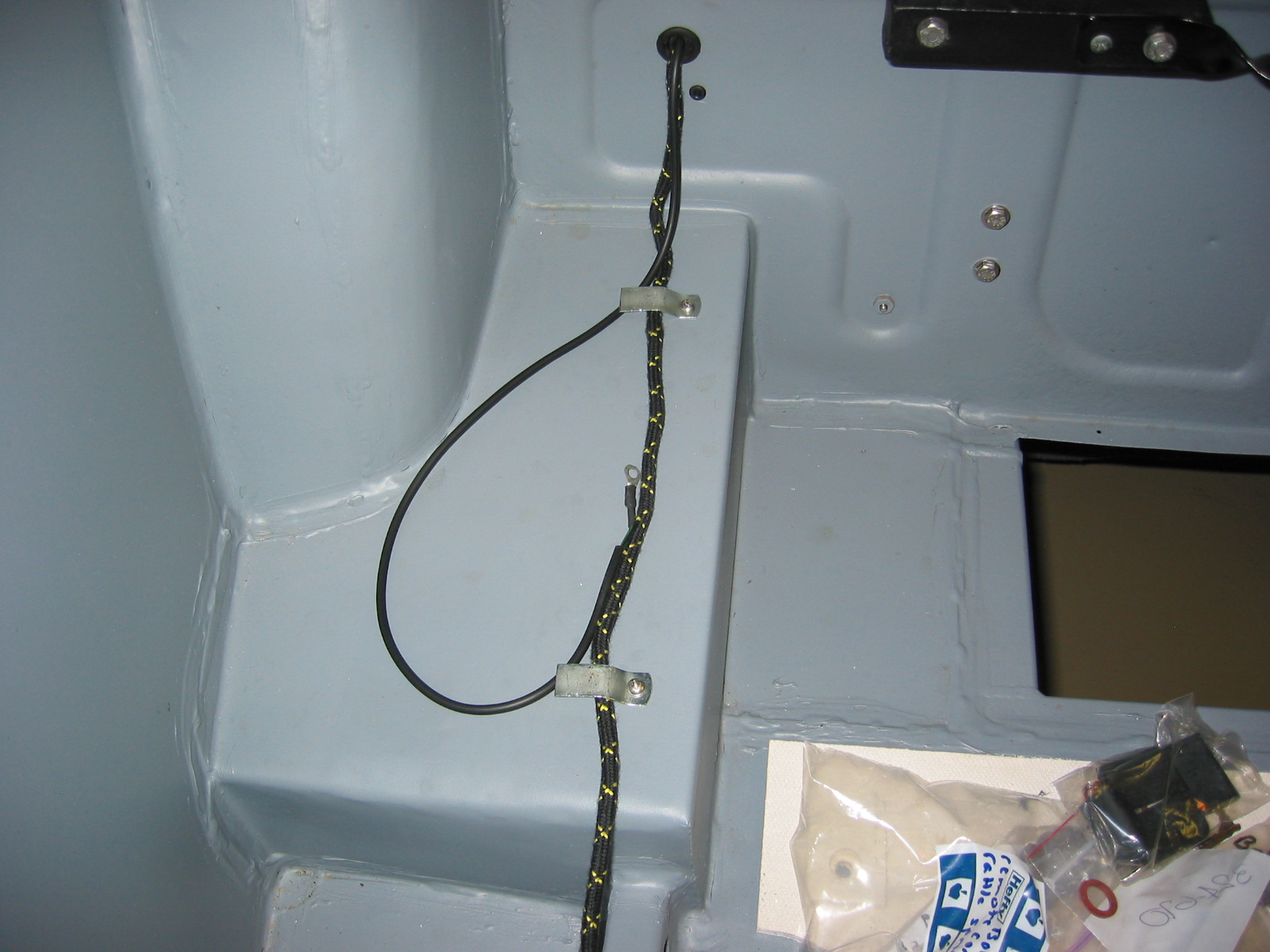
Battery Cable – Installed the battery cable ordered from British Car Specialists. The cable set was expensive, but of high quality. Installed rubber grommets in boot kick panel wall. Clip 1 was attached to the right bump box (Should install the cable on the box before it is mounted on the body.) Clip 2 was attached to the kick panel above the shock mounting bracket. The cable was then routed inside of the right frame rail.
Battery Cable 2
Battery Cable 1
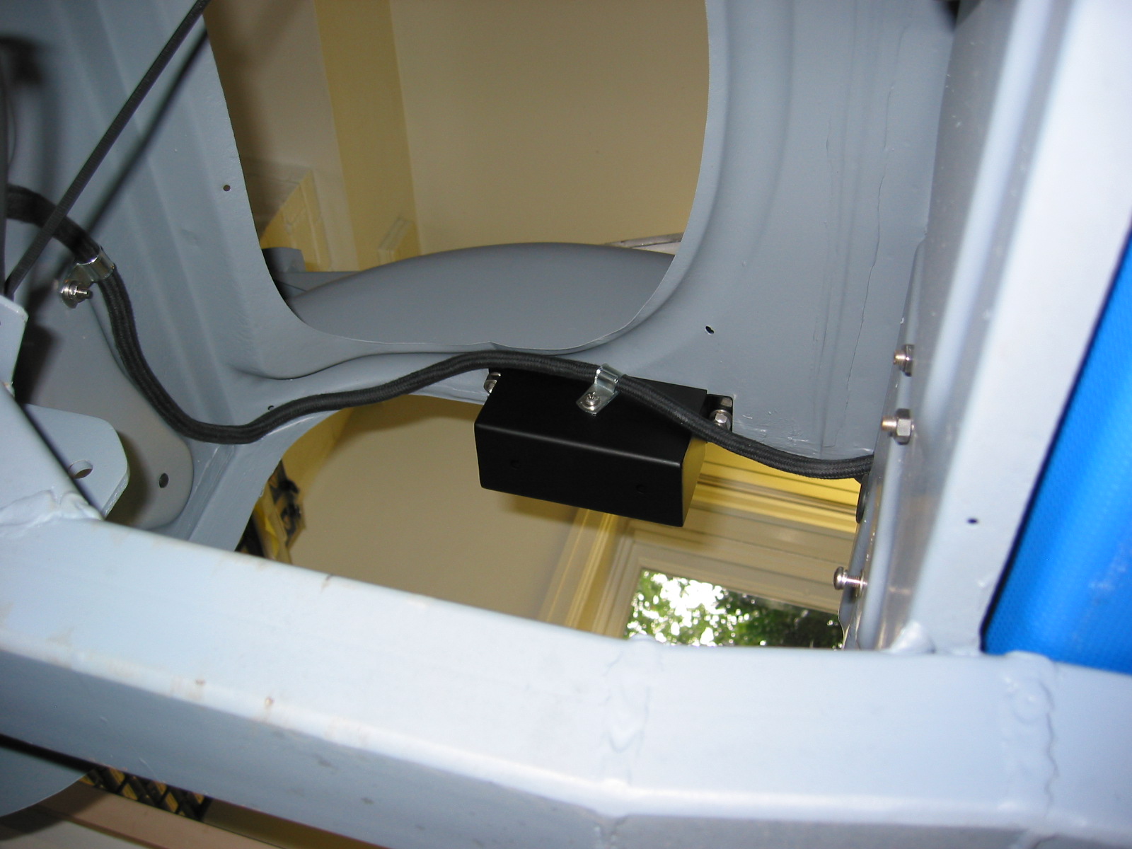
Battery Cable 3
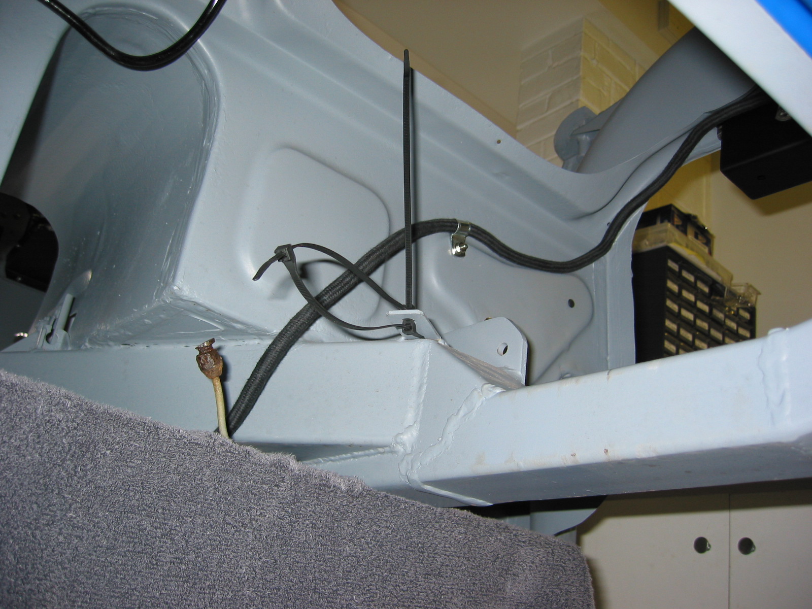
Battery Cable 4
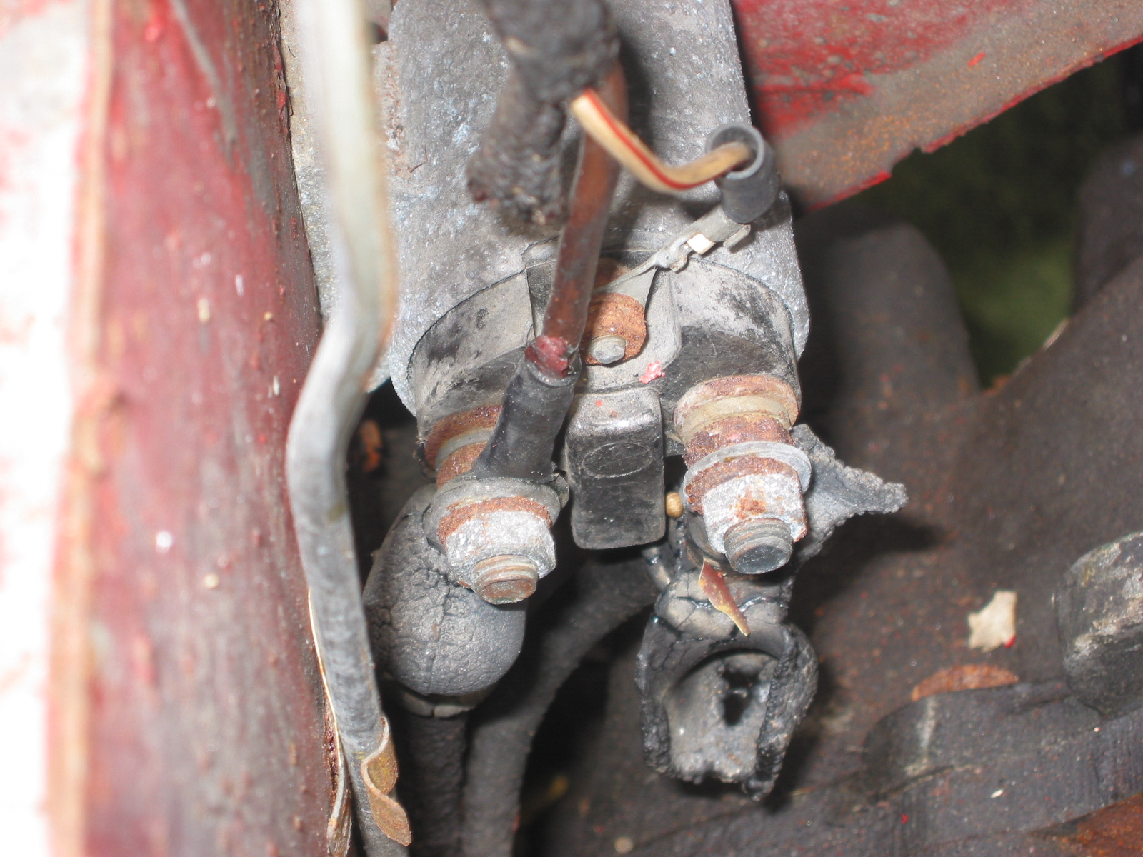
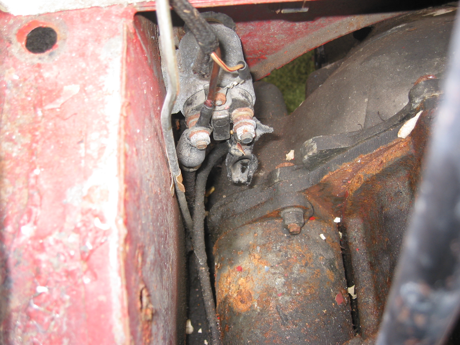
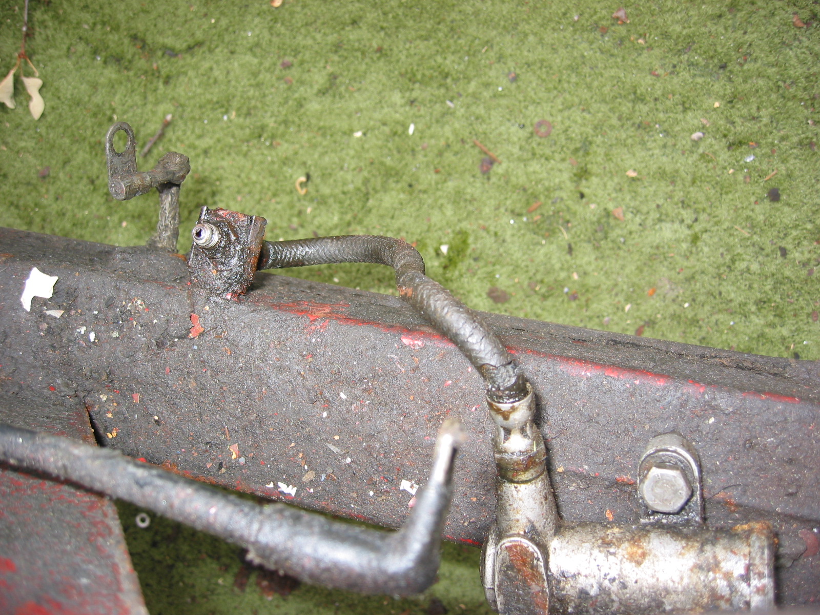
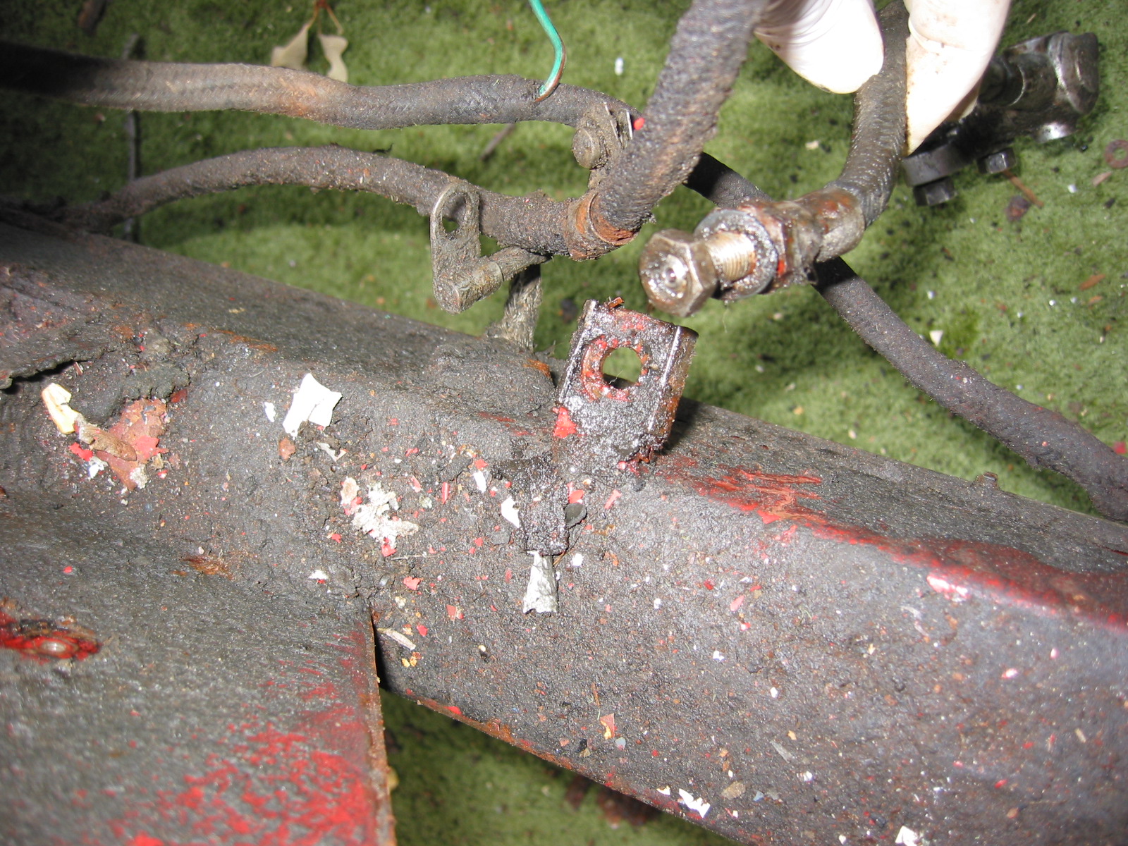
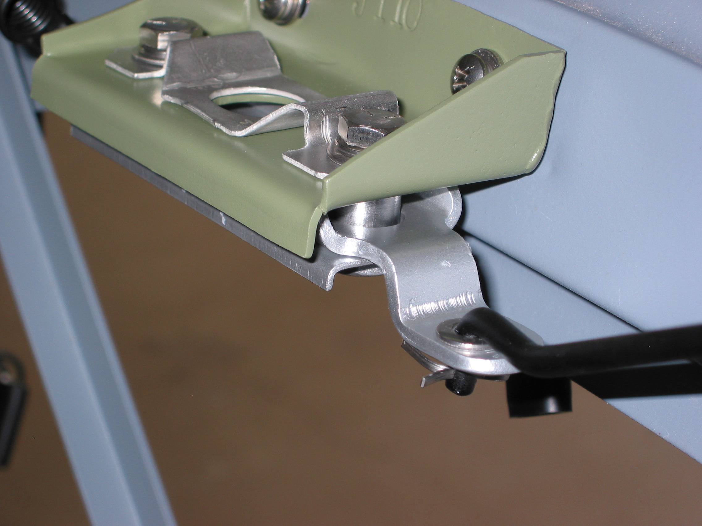
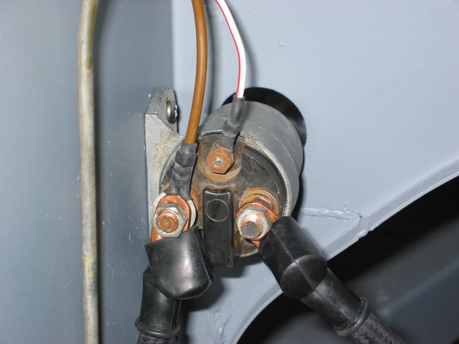
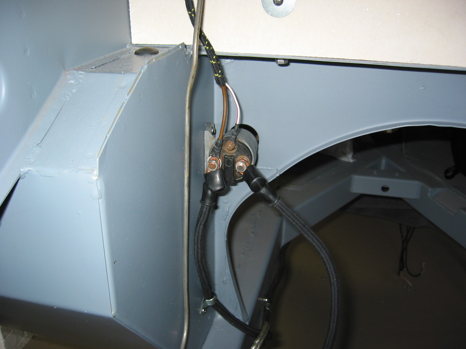
Clip 3 and clip 4 were located at the back of the cruciform. Clip 5 was located at the front of the cruciform near the gearbox mounting bracket. Clip 6 was located on the frame rail about 6” from the ground cable mounting. Clip 7 was mounted on the right footbox wall with the cable directed to the right terminal of the starter solenoid. The Cable from the starter to the left terminal on the solenoid was then secured. The white/red stripe wire fastened to the small terminal on the solenoid. Three “cert” nuts need to be installed – two for the solenoid and one for the clip on the footbox.
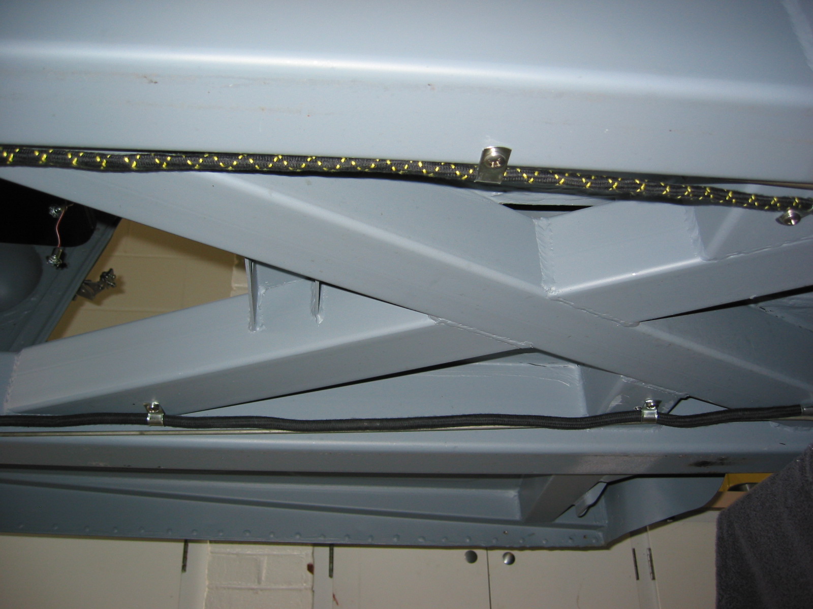
Battery Cable 5
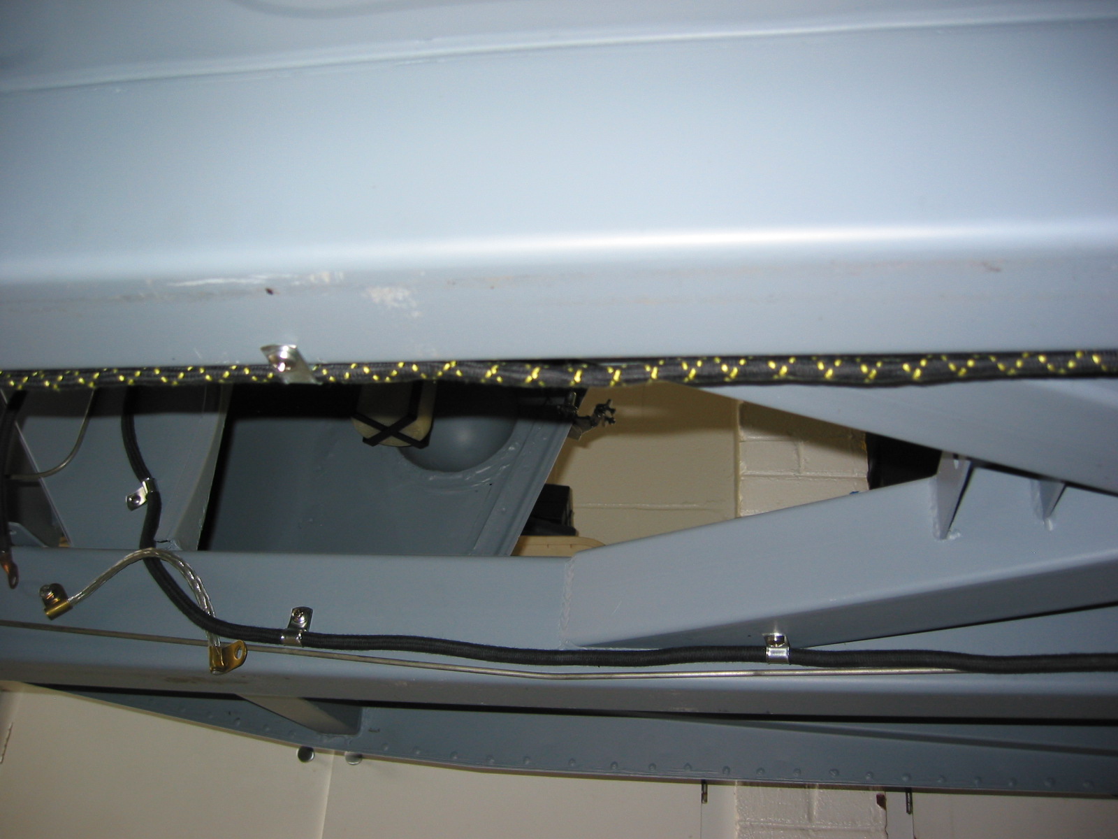
Battery Cable 6
Battery Cable 8
Battery Cable 9
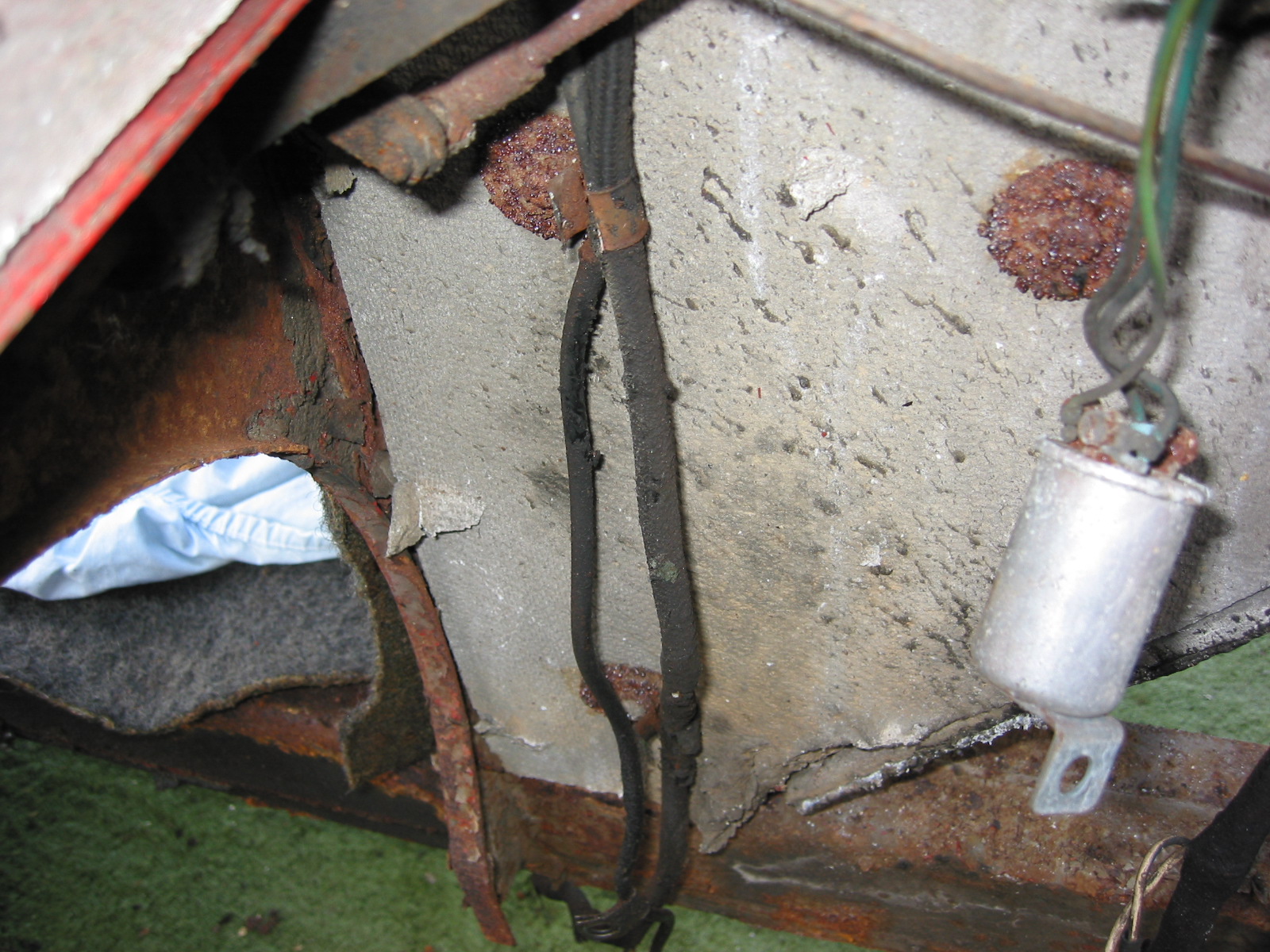
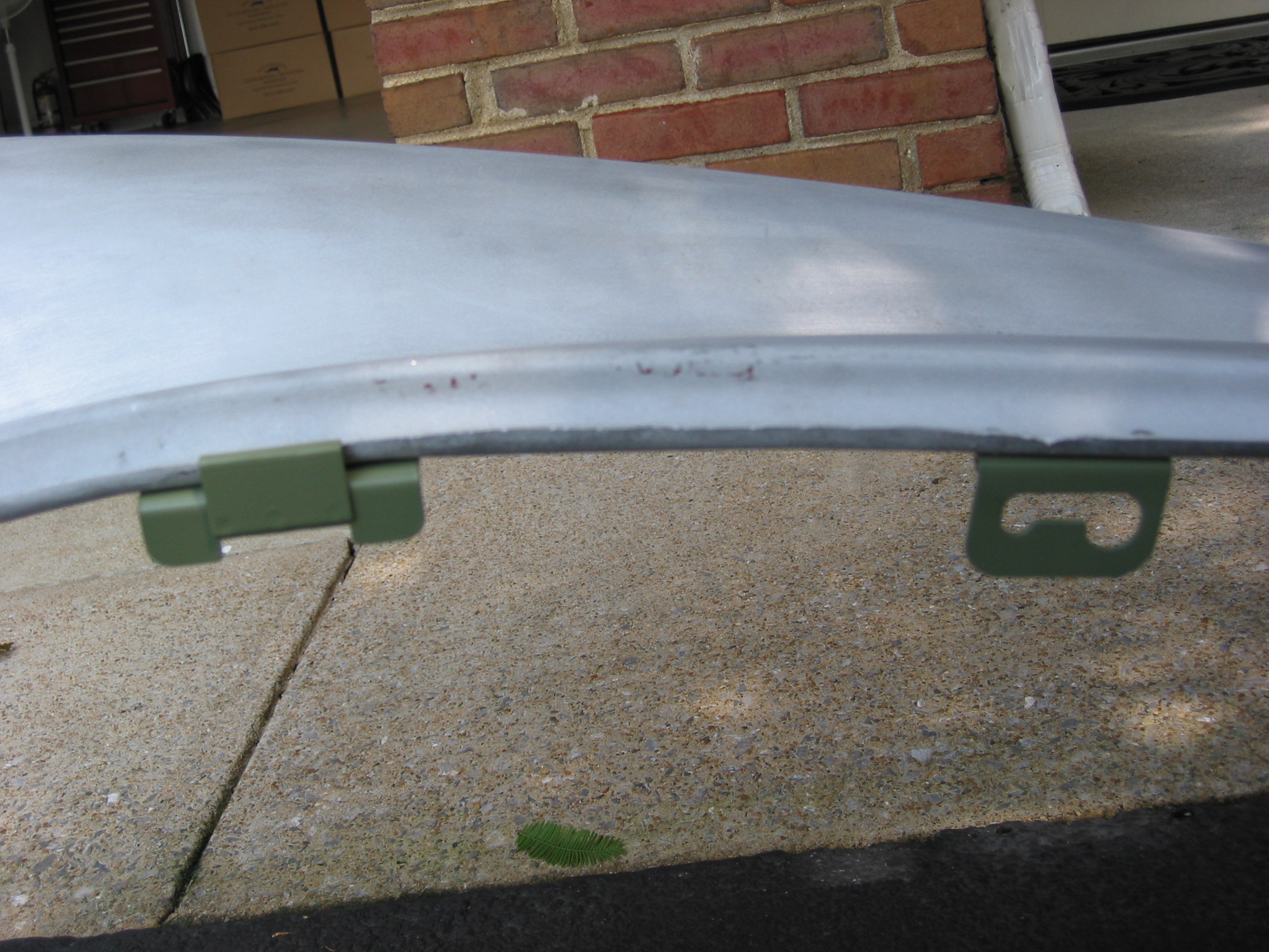
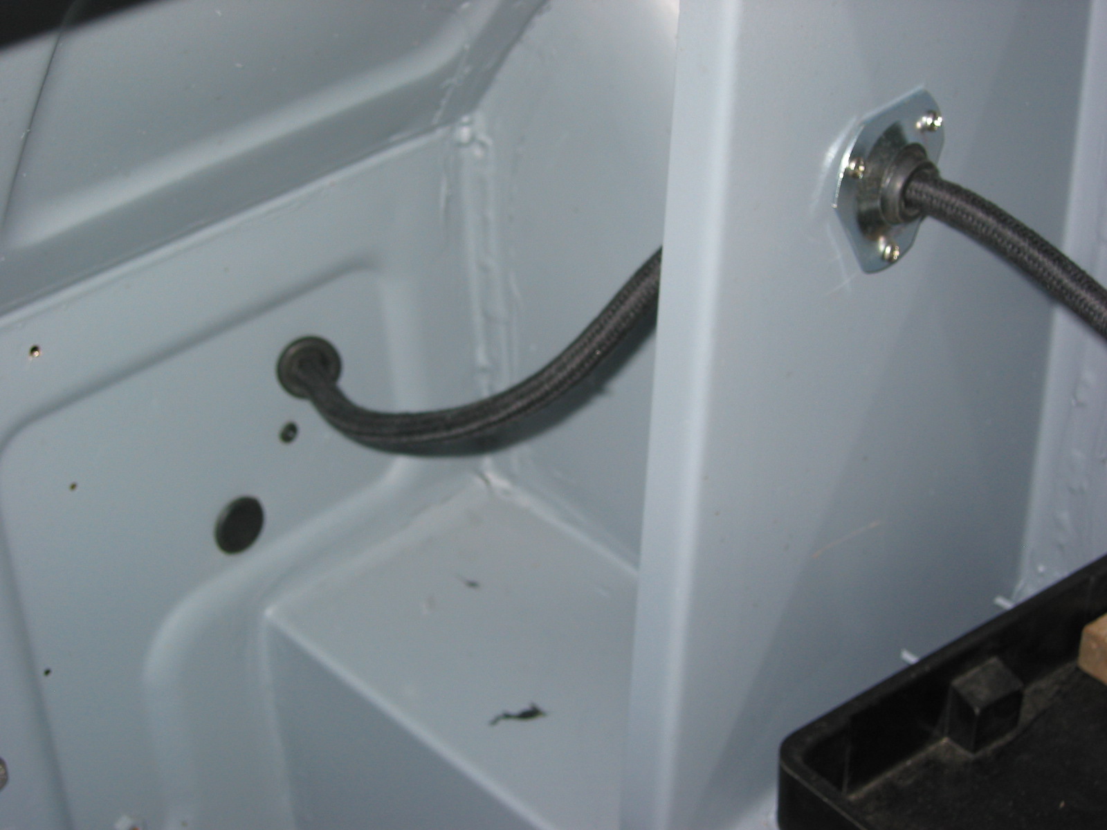
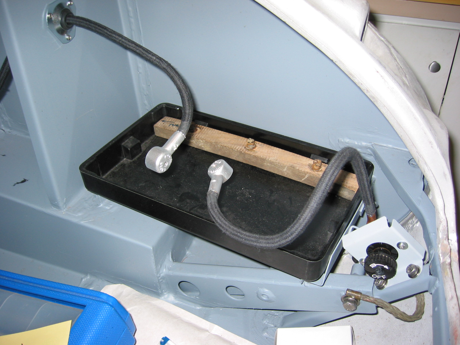
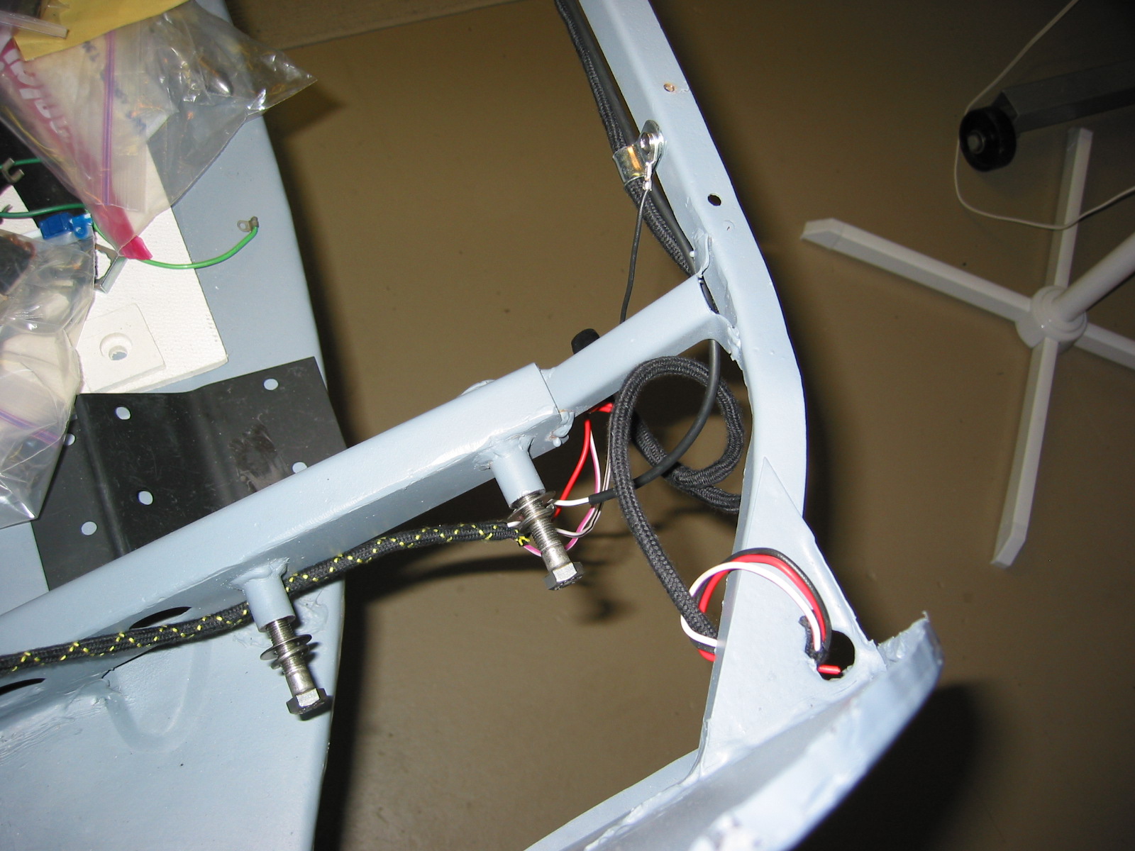
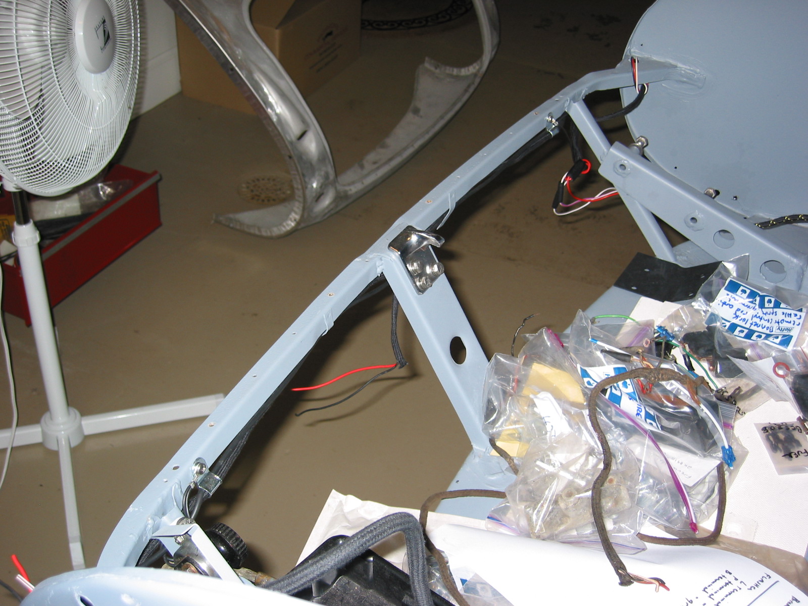
Next, the rear lights harness was installed. Clip 1 was secured at the right upper fuel pump bracket. Clip 2 was secured on the kick panel to the left of the pump. Clip 3 was attached to the left bump box and the wiring was threaded through the boot wall. The green wire will connect to the fuel gauge sending unit. Metal tabs were fabricated from clips and mounted on the floorboard of the boot.
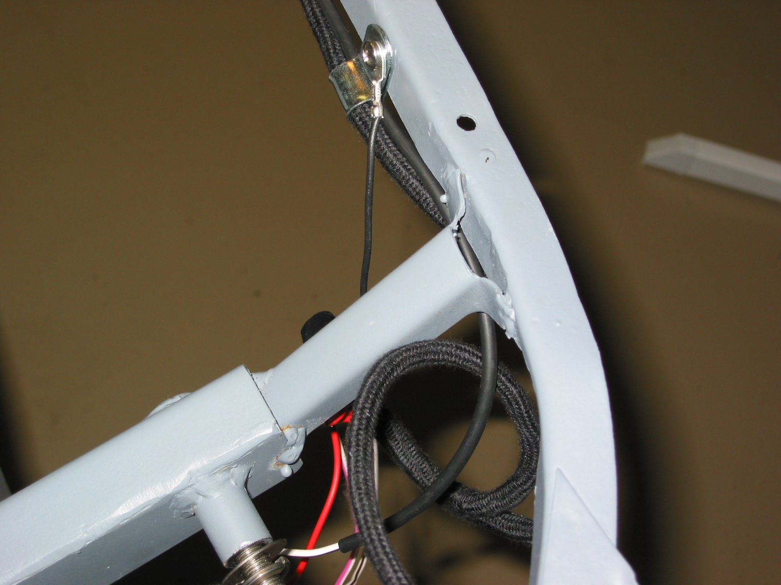
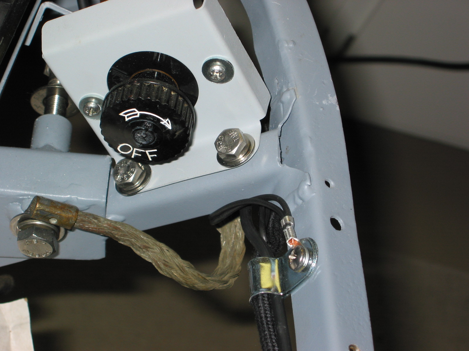
Single bullet connectors were used to join the main harness to the rear light harness and link the white/black wire, and the white/purple wire. The red wires were connected using a double rubber connector. Clips 3 and 4 were mounted to the rear rail. The long separate white/black wire was also routed through and it connected to the single screw terminal on the battery on/off switch. Black ground wires were connected to the screw on each clip.
Boot Wiring 1
Boot Wiring 2
Boot Wiring 3
Boot Wiring 6
Boot Wiring 4

Boot Wiring 5