
August 17, 2002
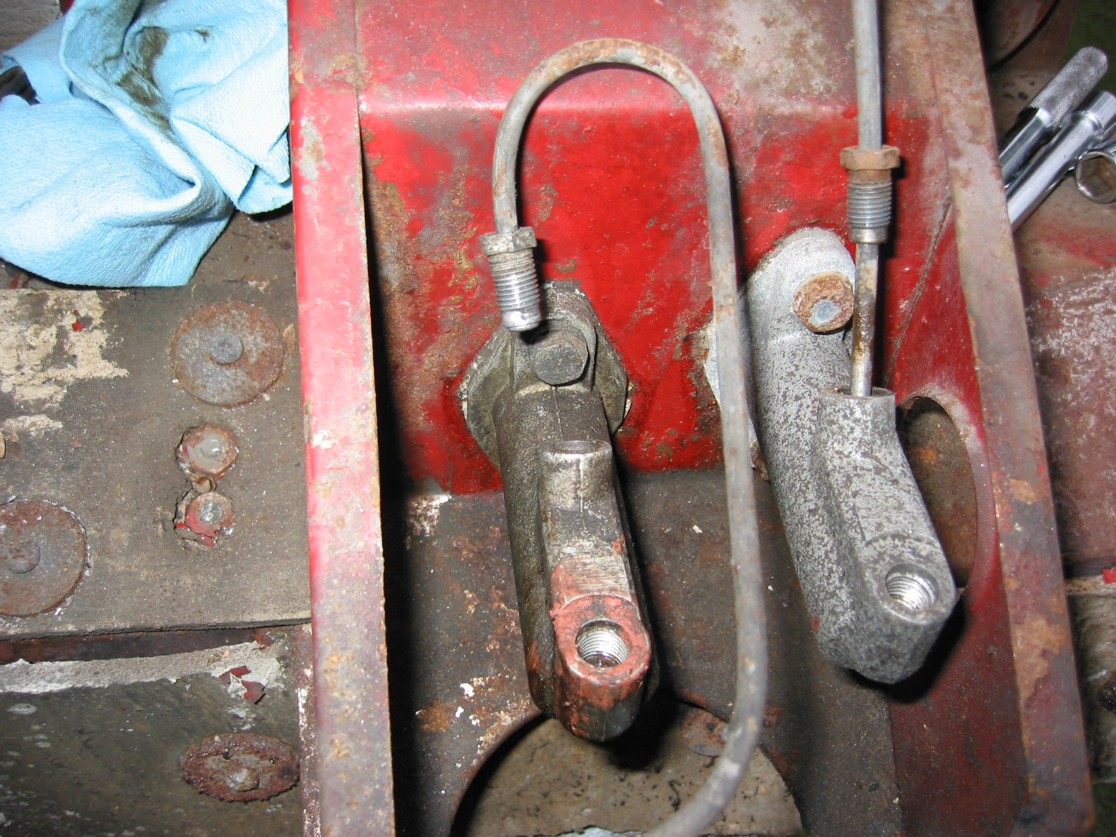
Brake and Clutch Master Cylinders – Loosened lines from cylinders. The brake line from the master cylinder to the 4 way junction has 3 clips and fasteners to the union facing the master cylinder (left side of the car). The clutch line also has three clips: 1 by the solenoid, and 2 on the firewall (high).
Loosen the 1/2” bolts securing the clutch master cylinder. Pull the cotter pin on the master cylinder shaft to the pedal. Remove the master cylinder. Same procedure for the brake master cylinder. There are aluminum spacers on the top of each master cylinder between the cylinder and the body.
Master Cylinders

Brake Pipe Junction 1
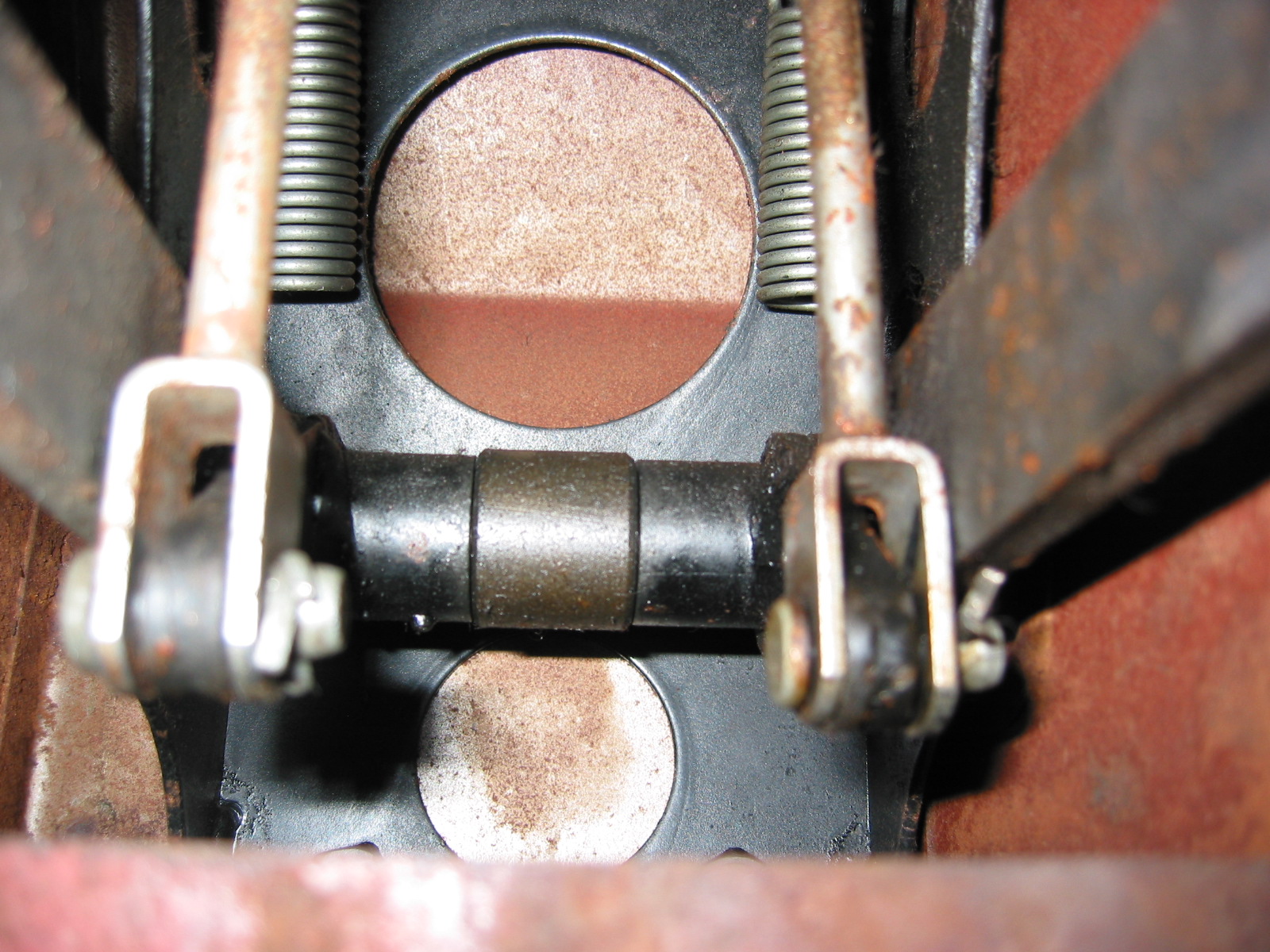
Pedal Box Connections

Pedal Box Bolts
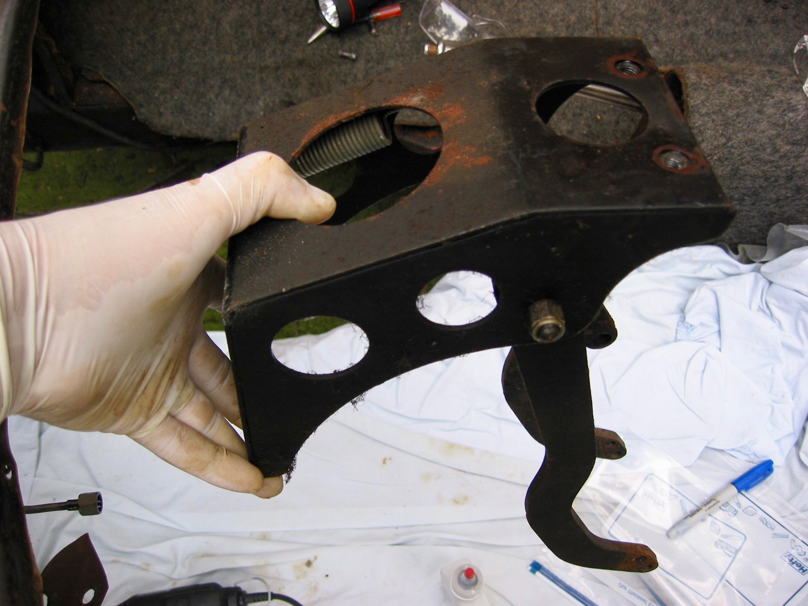
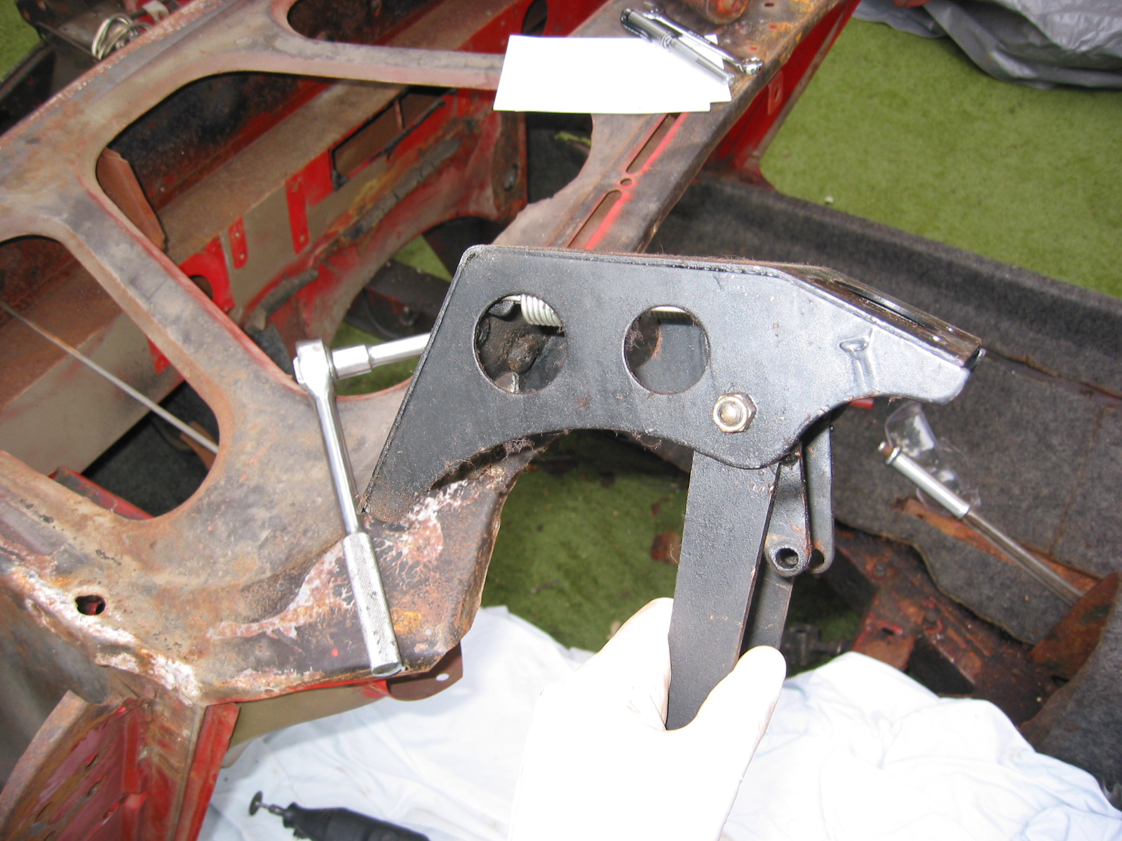
Pedal Box (Pedal Lever Bracket)
Loosen two 1/2” bolts to remove pedal box mechanism. The box is painted black. Unit will then drop out.
Pedal Box 1
Pedal Box 2
Headlamp Dip Switch Wiring – Pulled the wiring through the pedal box with rubber grommet.

Dipper switch wiring
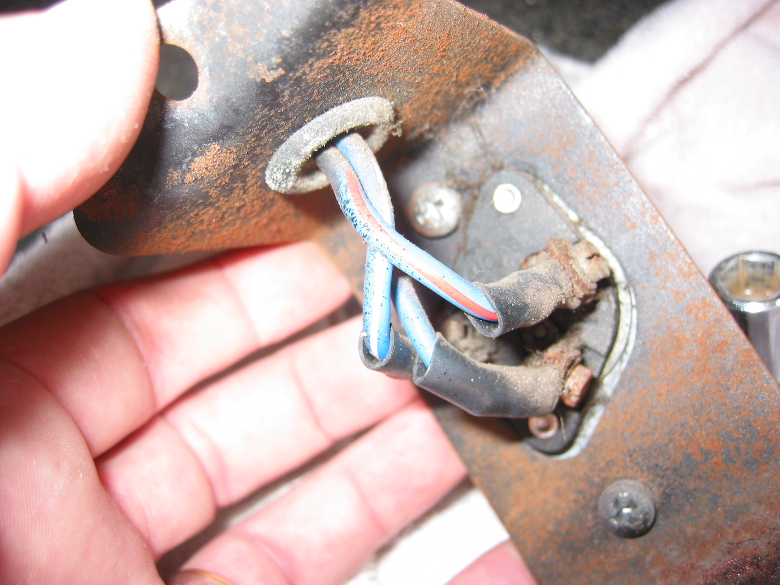
Dip Switch Wiring
Bulkhead Fresh Air Flange – Removed three phillips head screws securing the fresh air hose flange. Removed flange.
Air Tube Mounting
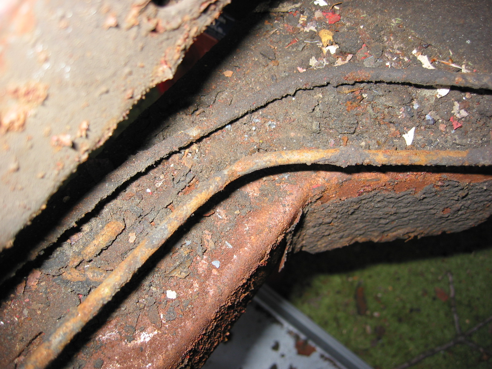
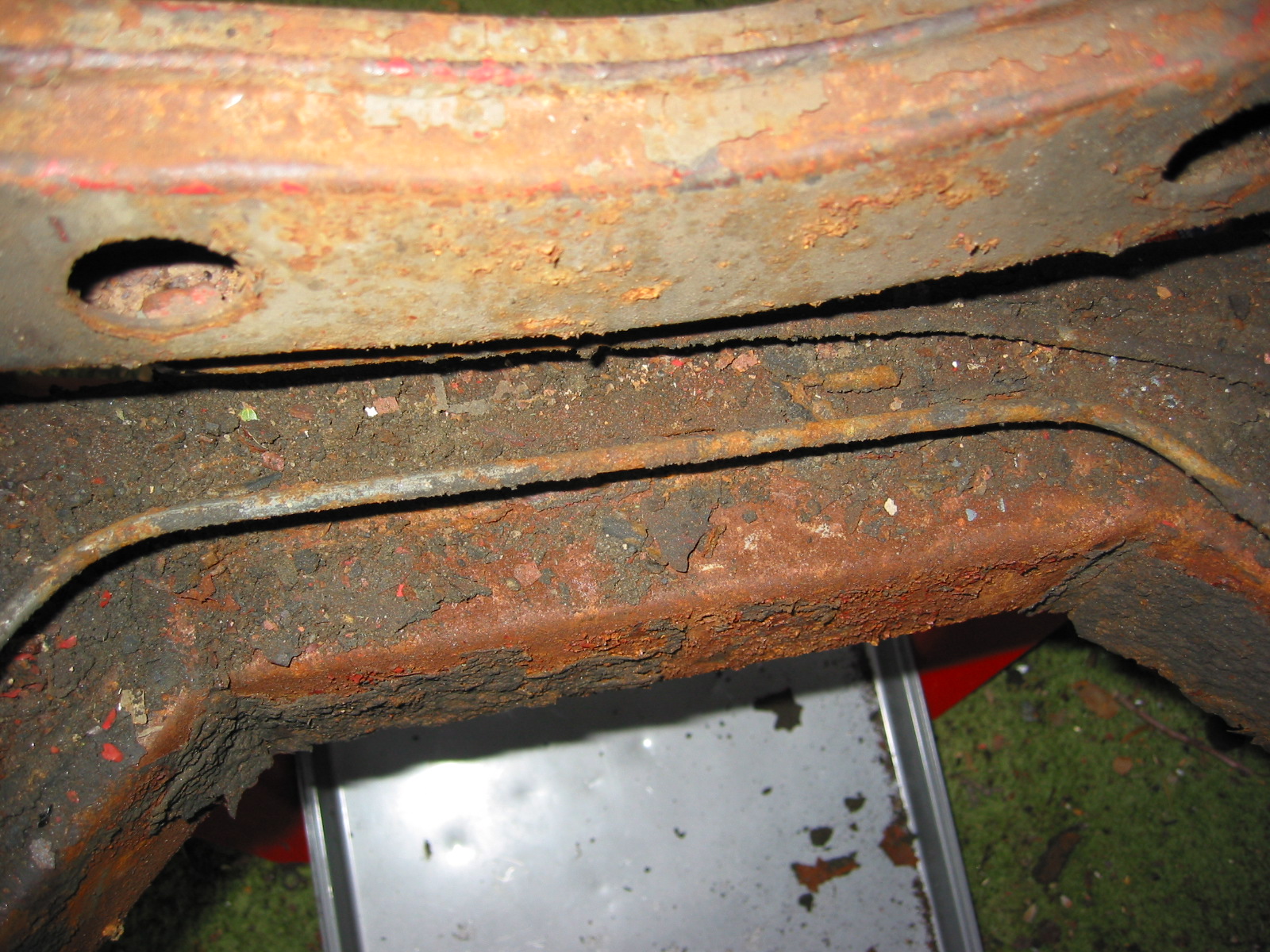
Brake Lines
The Brake Lines – fittings were loosened at the 4 way brake union to left front wheel – 2 clips at front cross bar to the front bottom union facing front of car at the junction. Removed right front brake line from junction to right wheel – top union on junction facing front of the car.
LF Brake Lines
Front Center Brake Lines
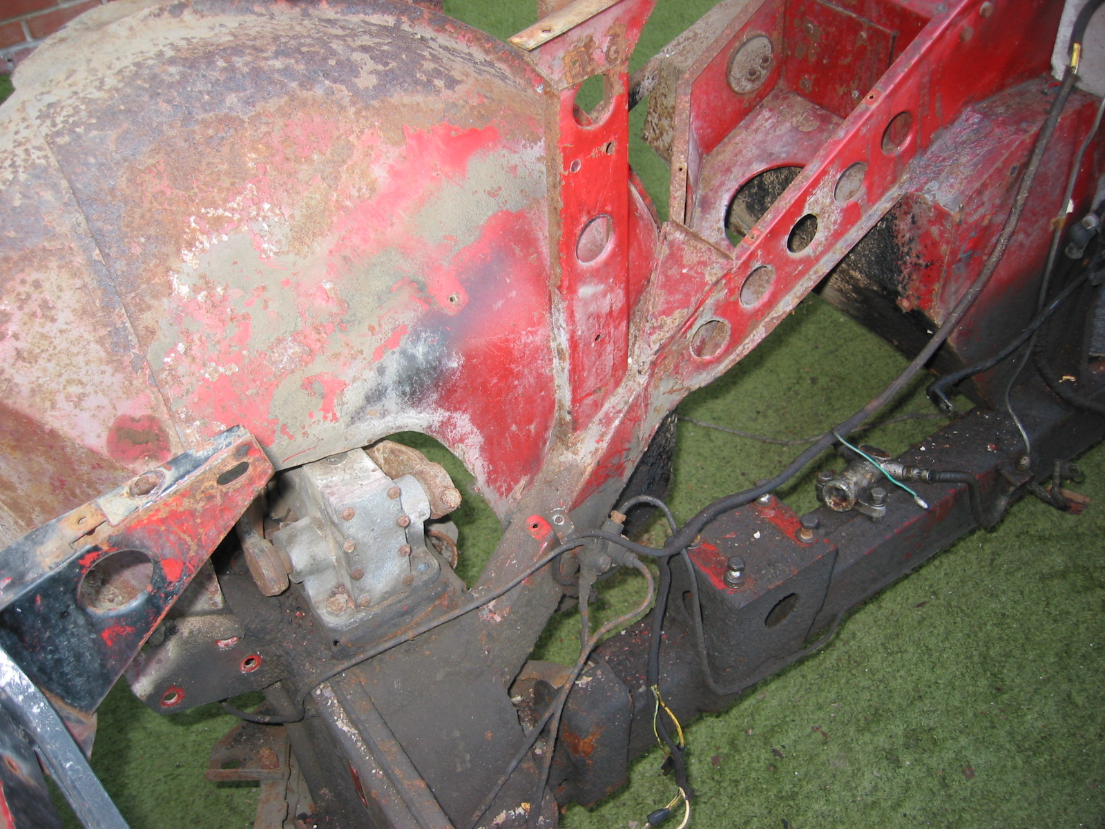
Brake Junction
Brake Junction connections

Brake Junction Fitting
Brake Junction 3
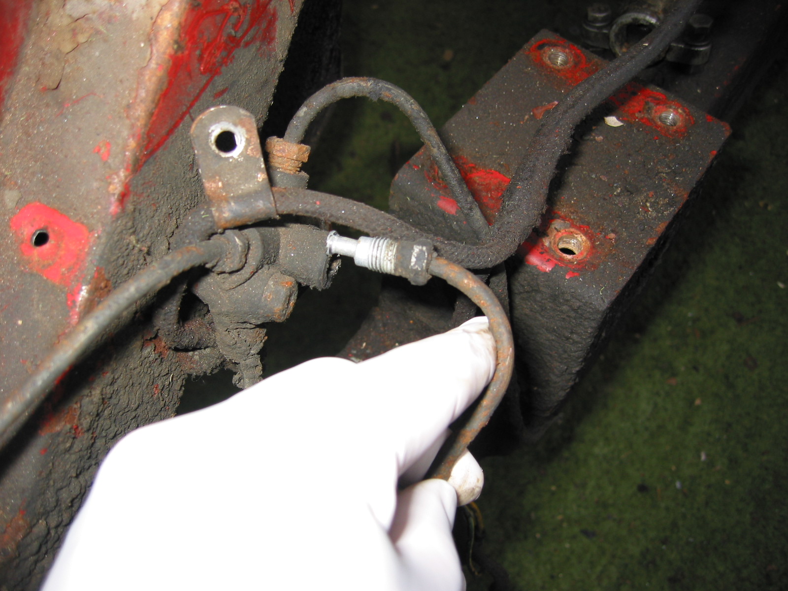
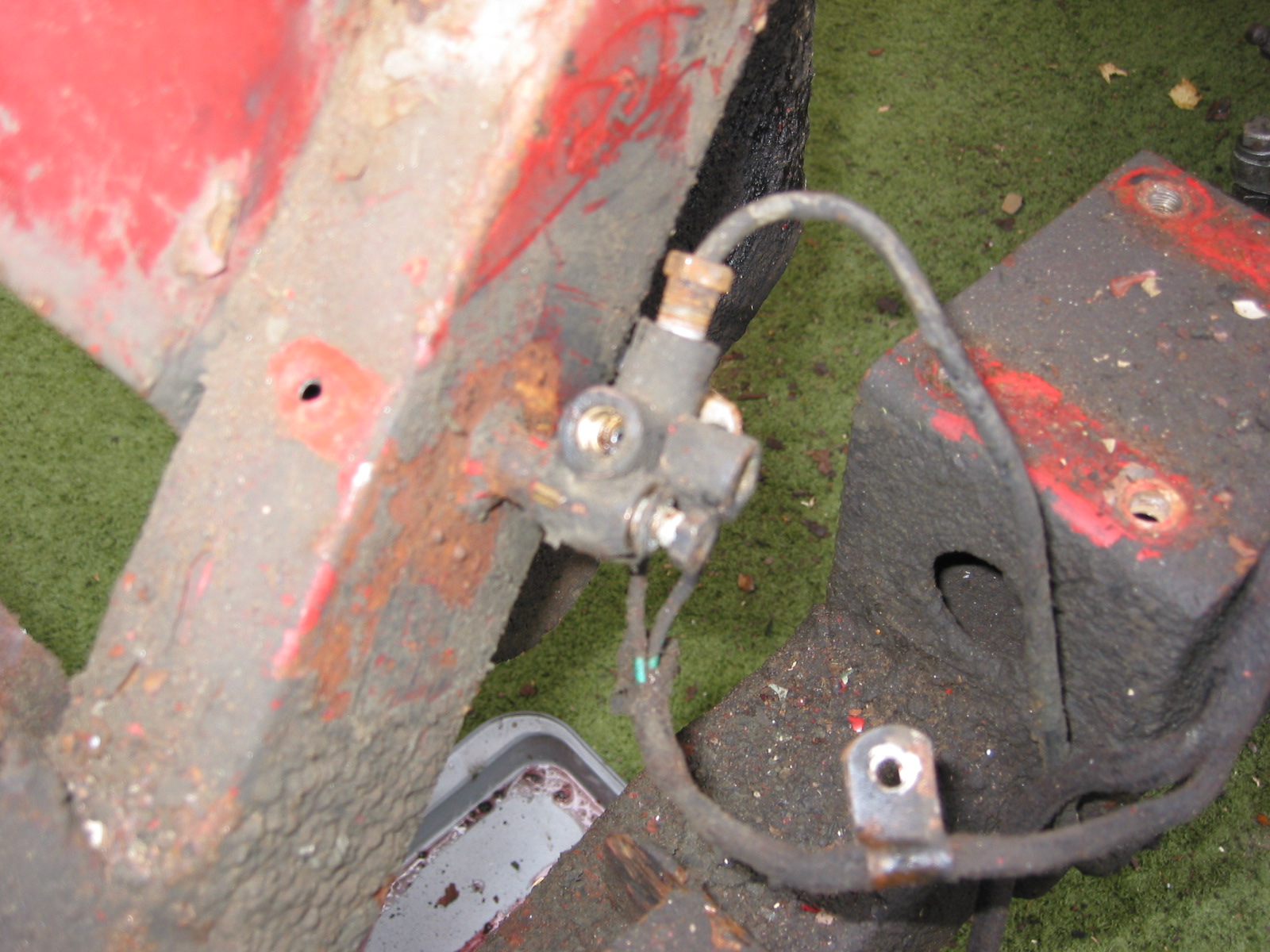
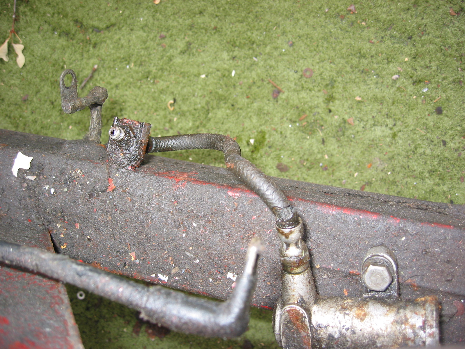
Brake 4 Way Union & Pressure Switch – Removed the Union by loosening one 7/16” bolt to frame. Two wires must be disconnected. Green goes to terminal closest to the engine. The green with pink stripe wire goes to the terminal closest to the frame. One clip holds wiring harness extension to the brake junction located just above the junction mounting post.
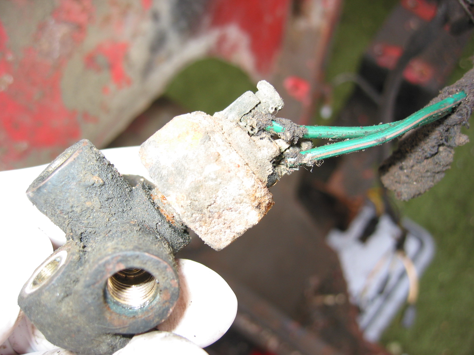
Brake Pressure Switch Wiring
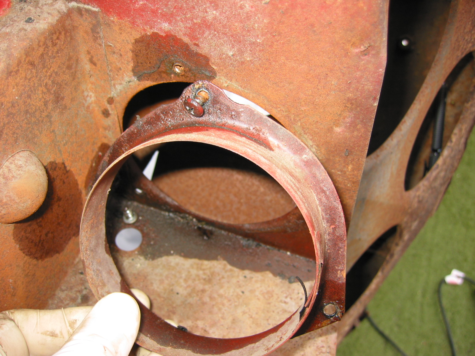
Master Cylinder Sealing Plate (blanking) – Removed the Plate on the right side of the car. Four Phillips head sheet metal screws. The plate had tar paper on back to seal it. Four clip nuts are used to hold the screws.
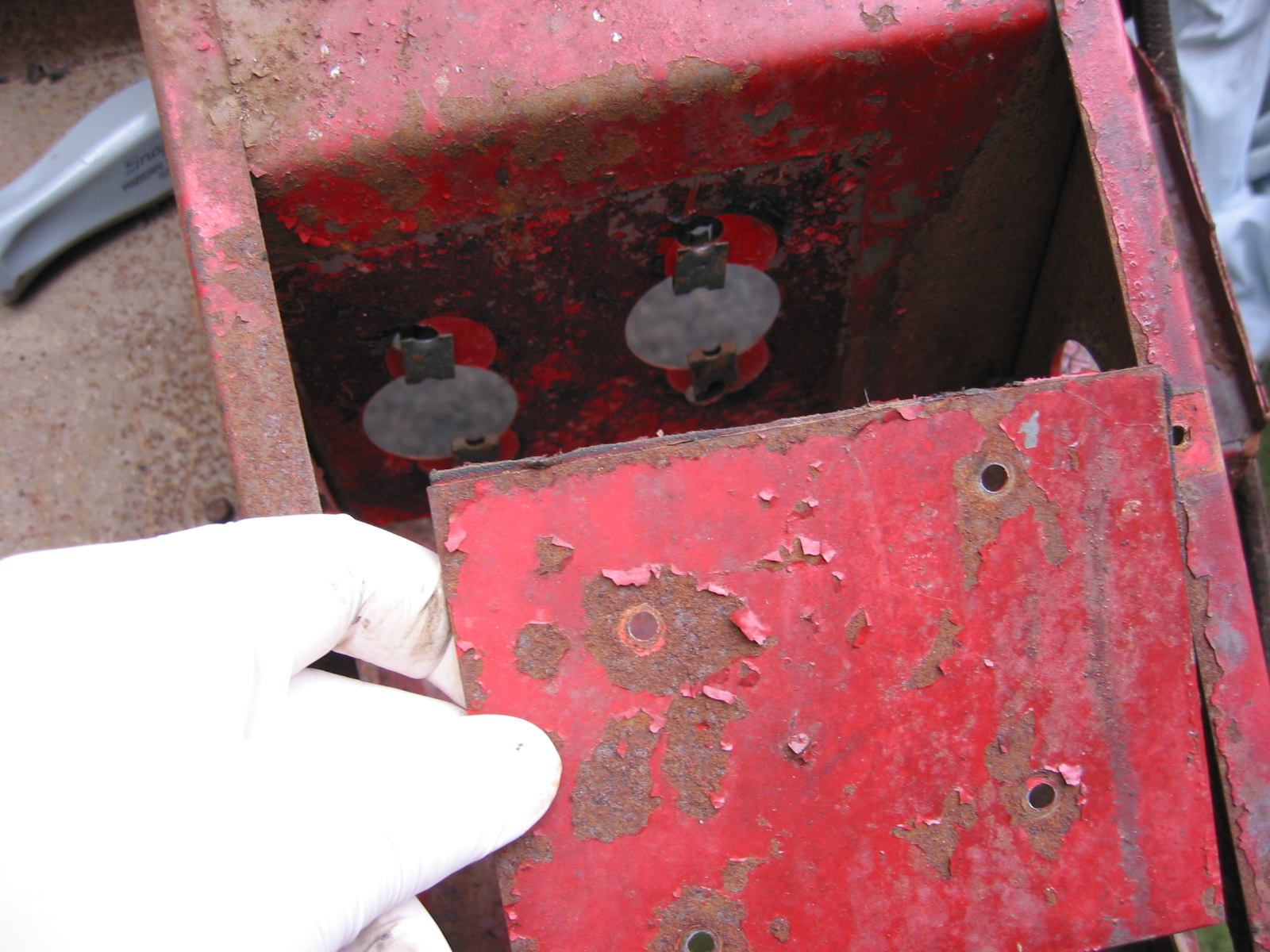
Right Sealing Plate

Right Sealing Plate 3
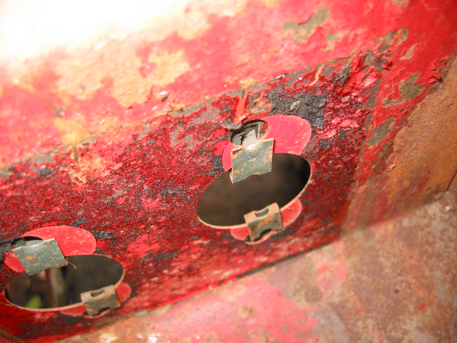
Right Sealing Plate 2
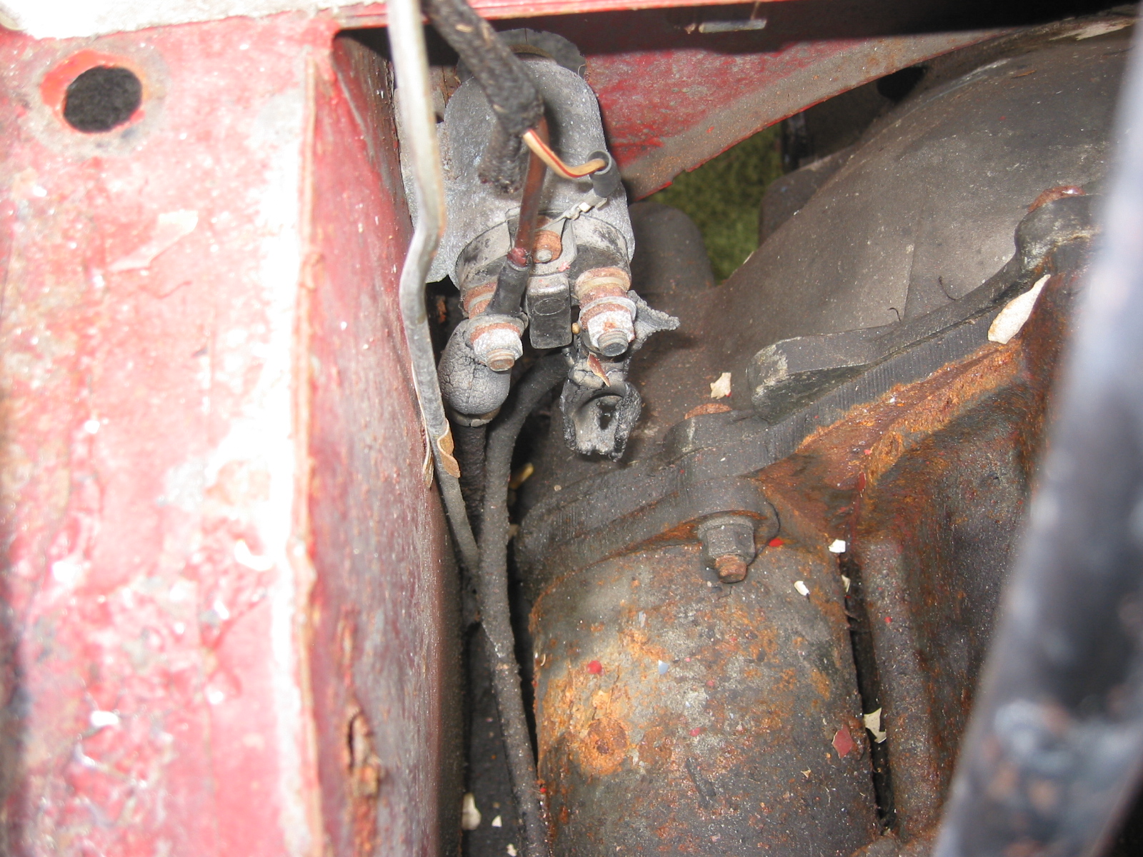
Starter Solenoid.
Disconnected the wiring for the starter solenoid. The terminal closest to the engine is for the high tension line from the battery. The terminal closest to the body is or the cable to the starter and the brown ignition wire. The white wire with the red stripe goes to the terminal on top.
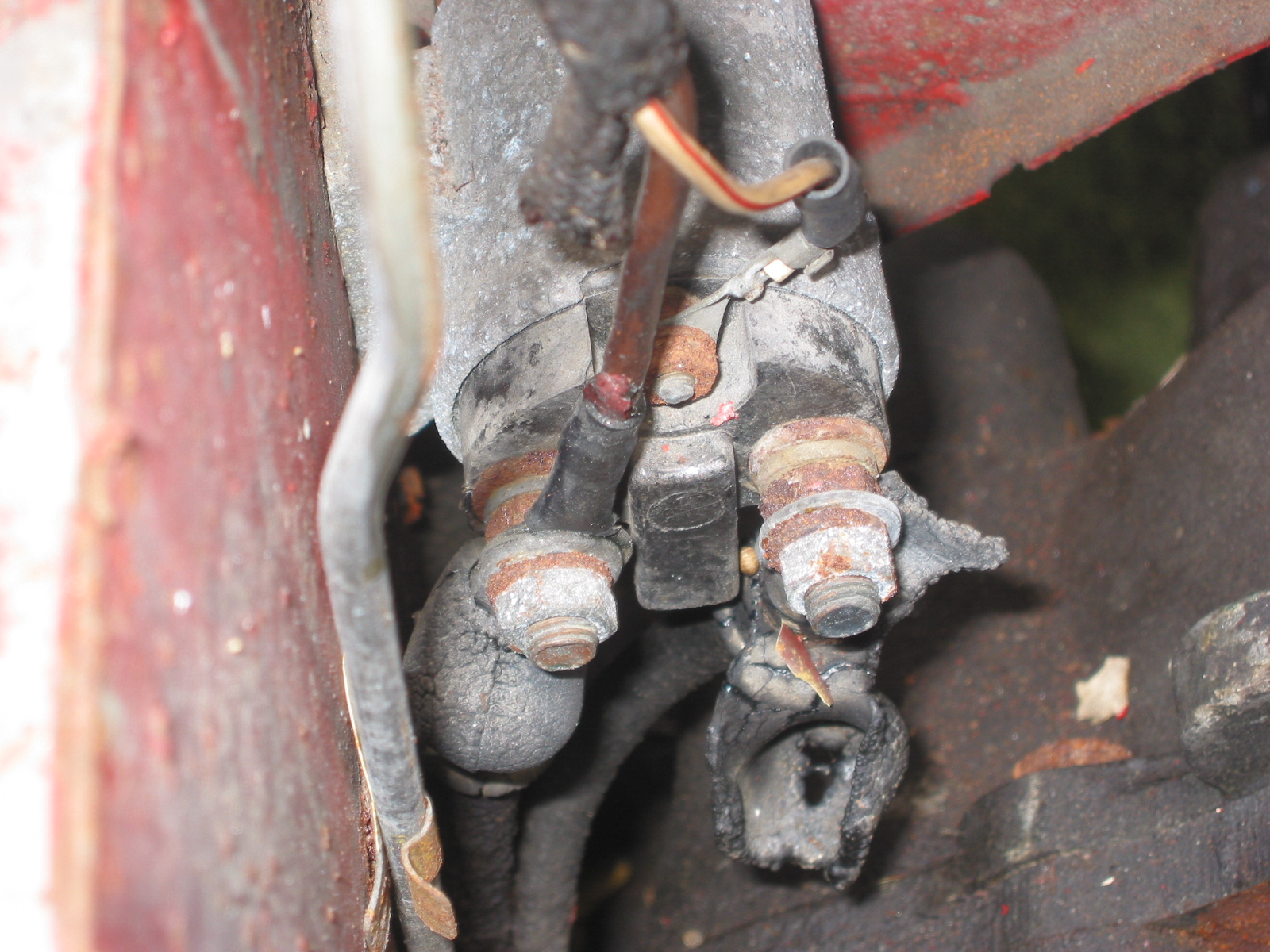
Starter Solenoid Wiring
Starter Solenoid 2

Starter Solenoid connections 2 & Clutch Pipe Clip
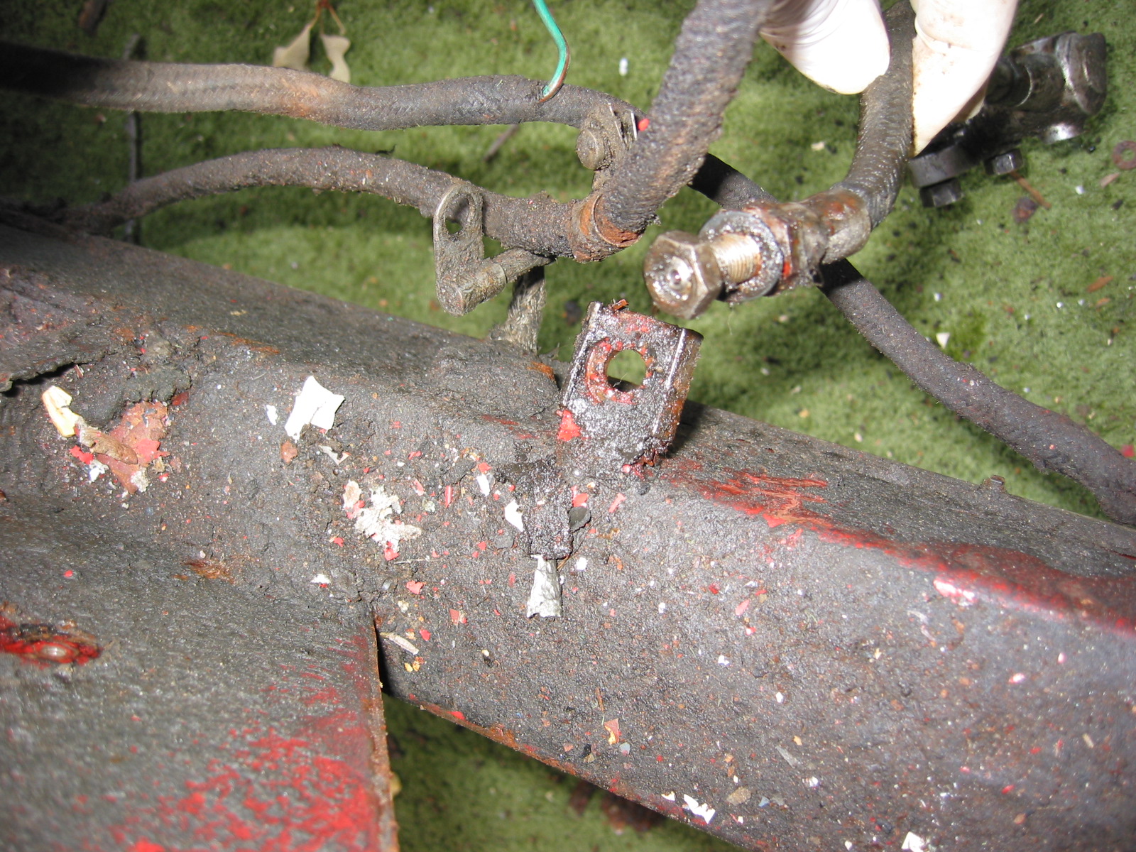
Blanking Bolts – Removed 2 blanking bolts in upper right footwell. Remove two blanking bolts in engine compartment to frame.
Right blanking bolts
Right footwell Blanking Bolts
Steering Wheel Blanking Plate – Removed the blanking plate on right side of car. Located behind the asbestos insulation. Four sheet metal screws.
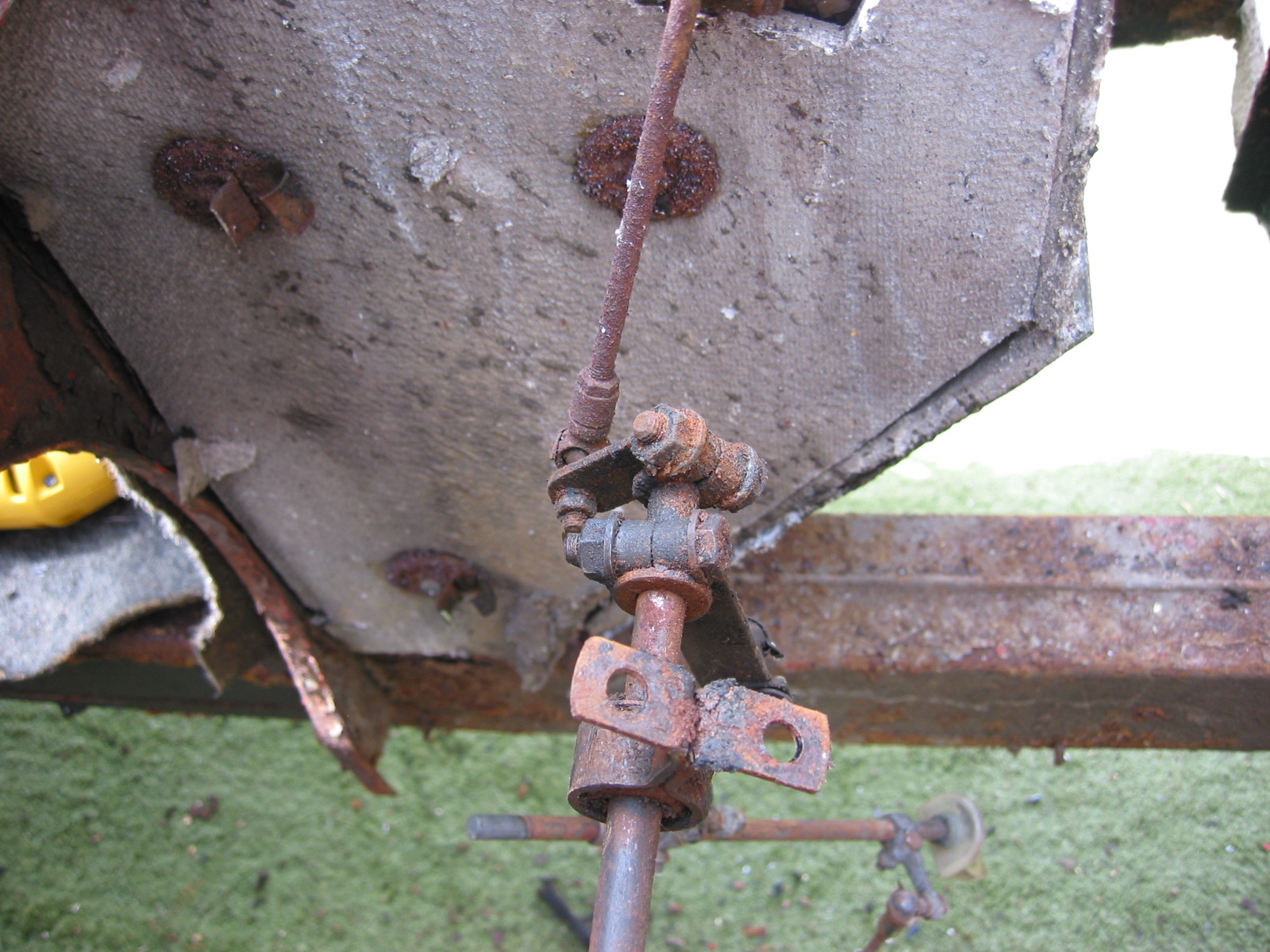
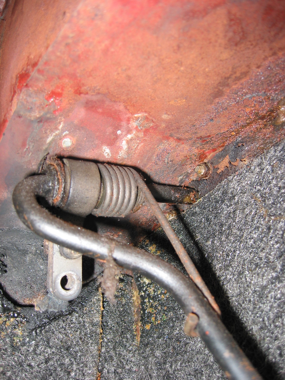
Slave Cylinder
Loosened one nut where hydraulic hose joins frame.
Slave Cylinder connection to Frame Clip
Slave Cylinder Mounting with Clip and shake proof washer
Fuel Line – Loosened the fuel line from the carb feed line and the fuel pump. Three to four clips run along the frame rail from carbs to fuel pump.
Wiring Harness – Carefully pulled the wiring harness from front firewall to the rear of the car. Approximately 10 screws through clips on frame. Also two screws and clips through asbestos insulation securing the harness.

Right wiring clamp
Voltage Box wiring
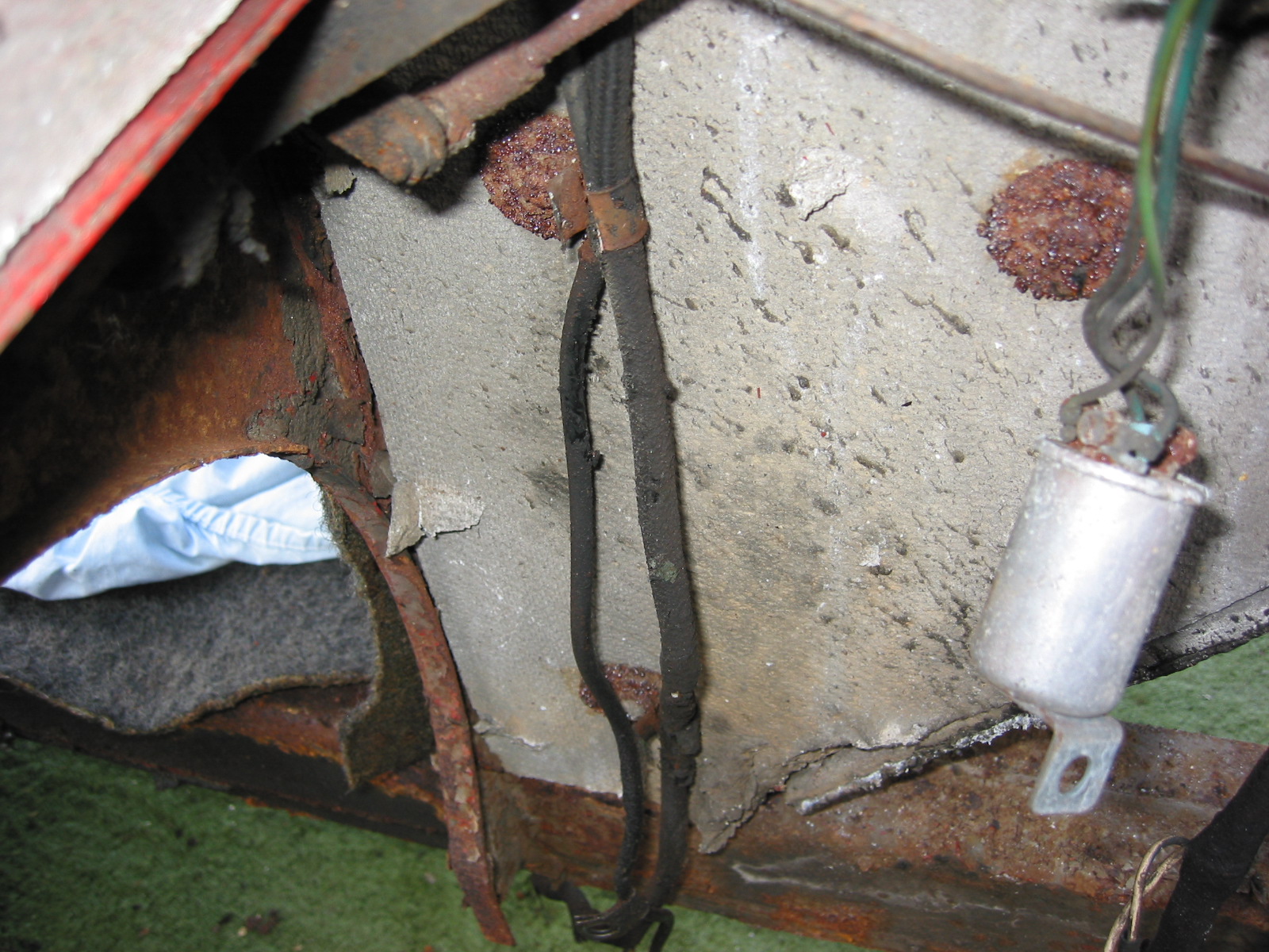
Wiring Clamps on Insulation 3
Firewall wiring clamp
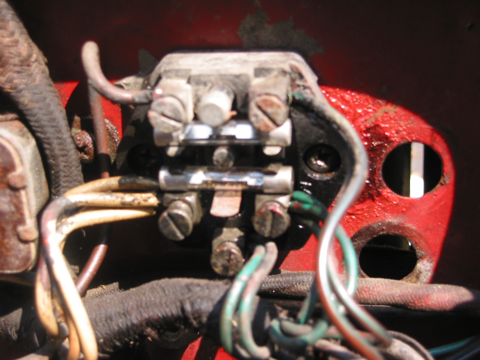
Overdrive switch – Wiring connections: Left terminal – white/purple stripe. Middle terminal – 2 white/green stripe wires. Right terminal – 2 solid white wires. Bottom terminal – black wire from harness.
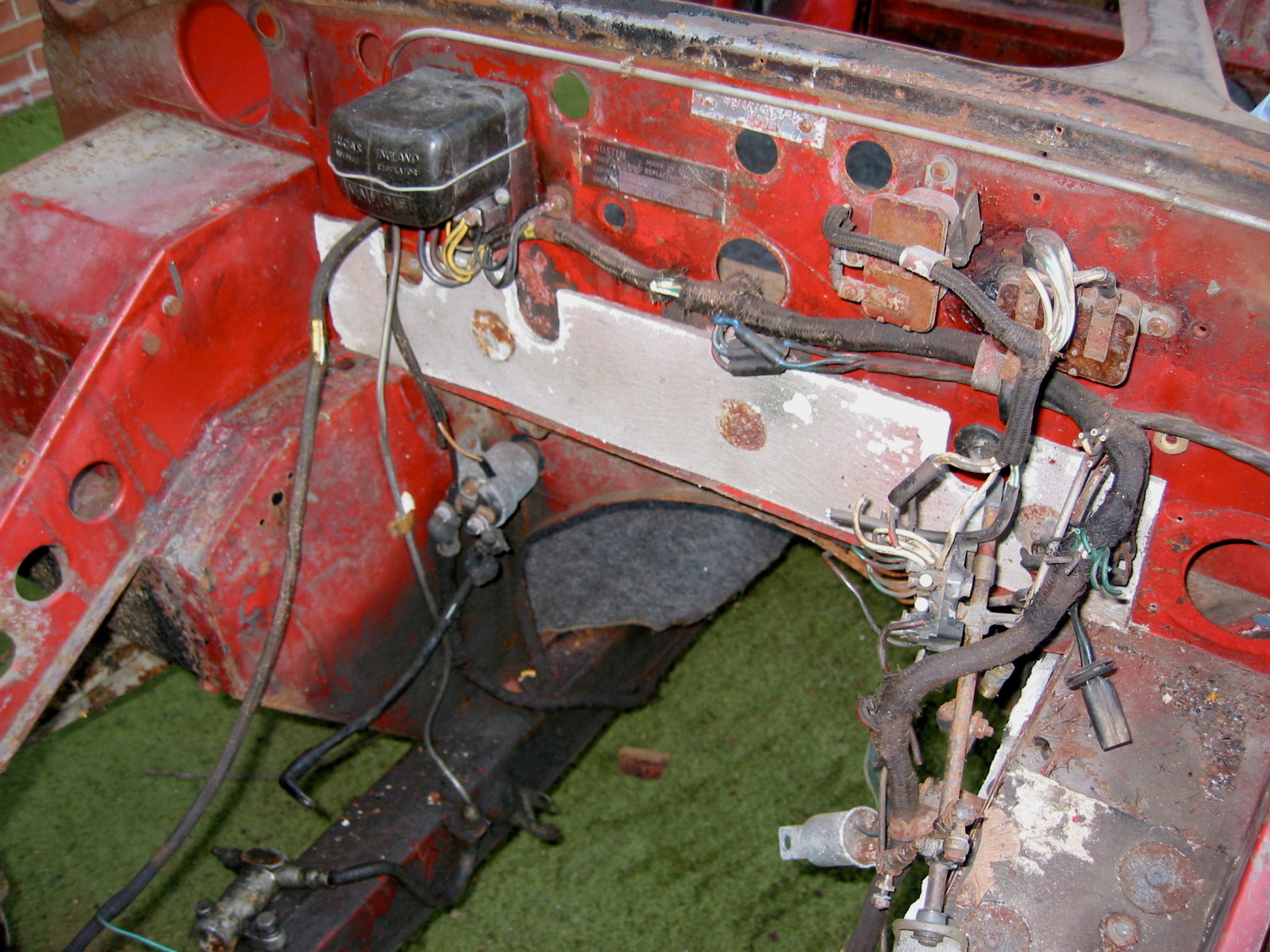
Firewall wiring harness
Overdrive relay

Relay wiring
Throttle Switch – Bottom terminal – white/ purple stripe wire. Top terminal – White/green stripe wire. See above.
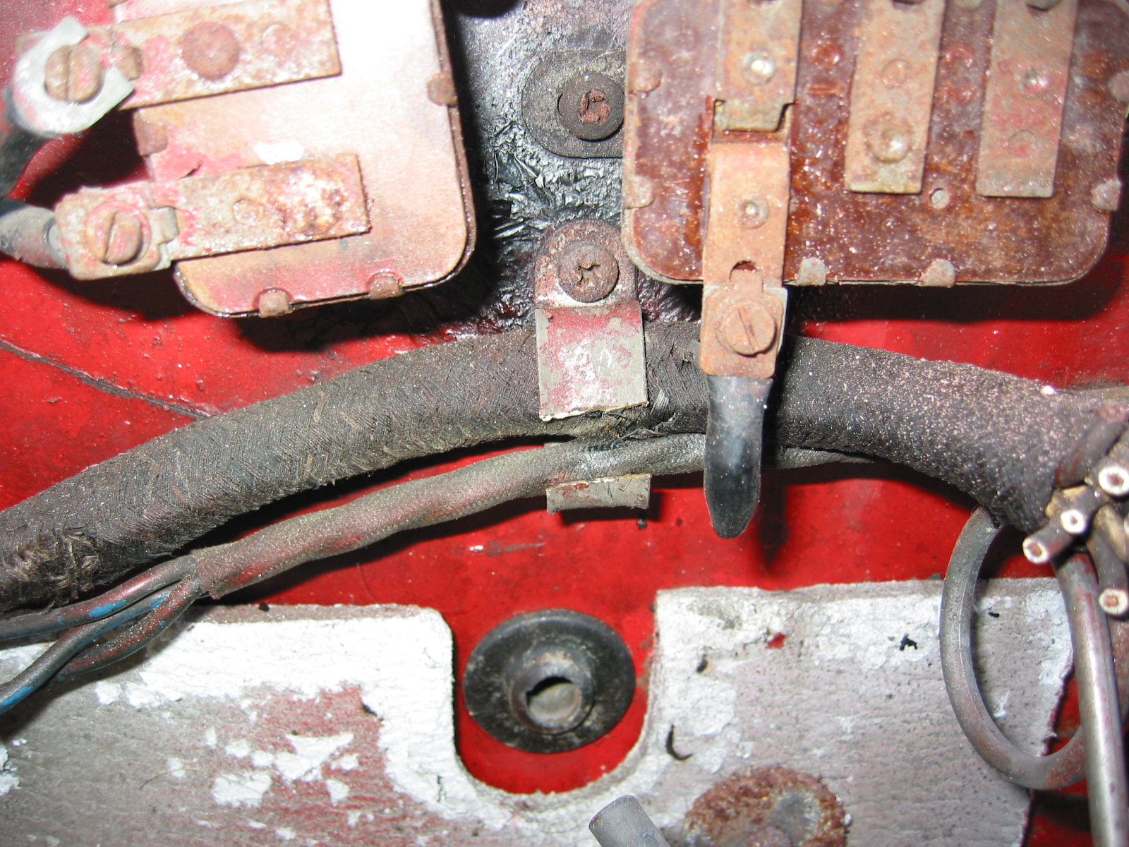
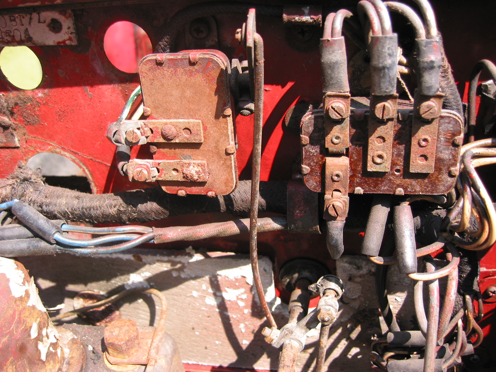
Fuse Block – After disconnecting the wiring to the block, two #10 machine screws were loosened to release the block from the firewall.
Fuse Block wiring
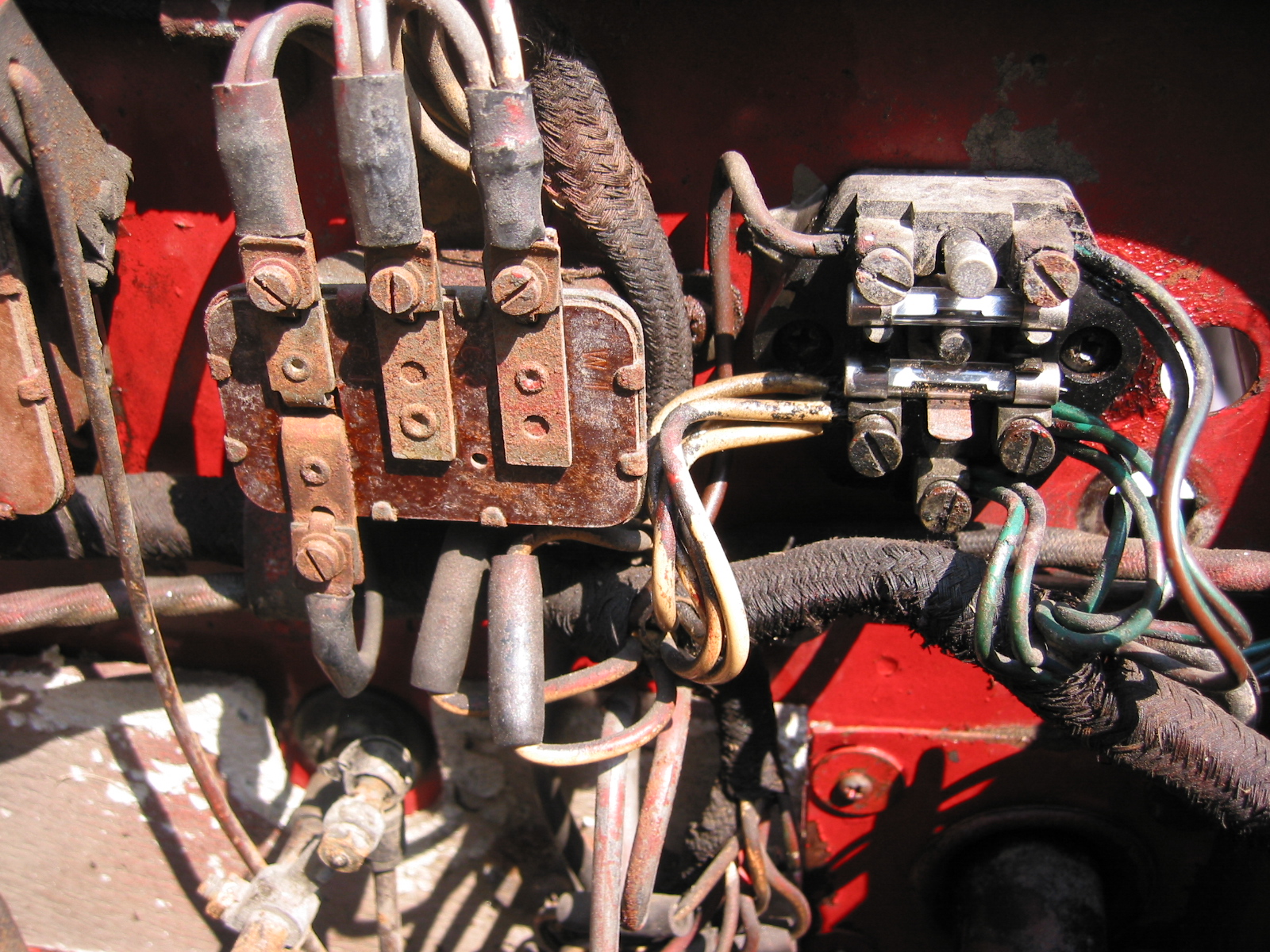
Fuse Block and relay
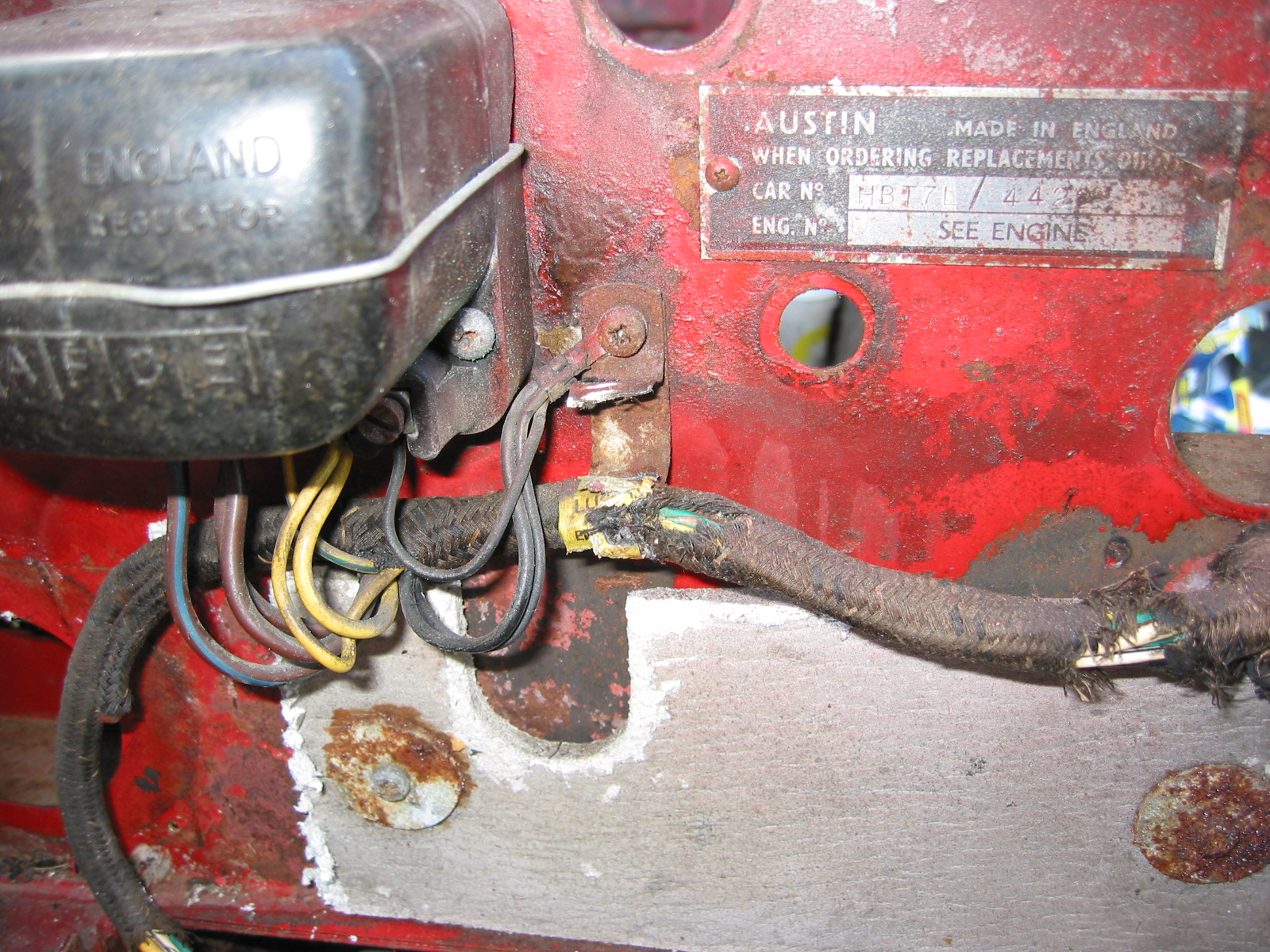
Voltage Regulator – Five terminals. Far left form driver’s perspective, labeled #1 with far left #5. 1 – black ground from adjacent screw. 2 – 2 solid yellow wires. 3 – 1 yellow/green stripe wire. 4 – 2 solid brown wires. 5 – 1 large brown/blue stripe wire. Note that there are three black ground wires to the adjacent firewall screw.
Voltage Box wiring
Voltage Box

Voltage Box (2)
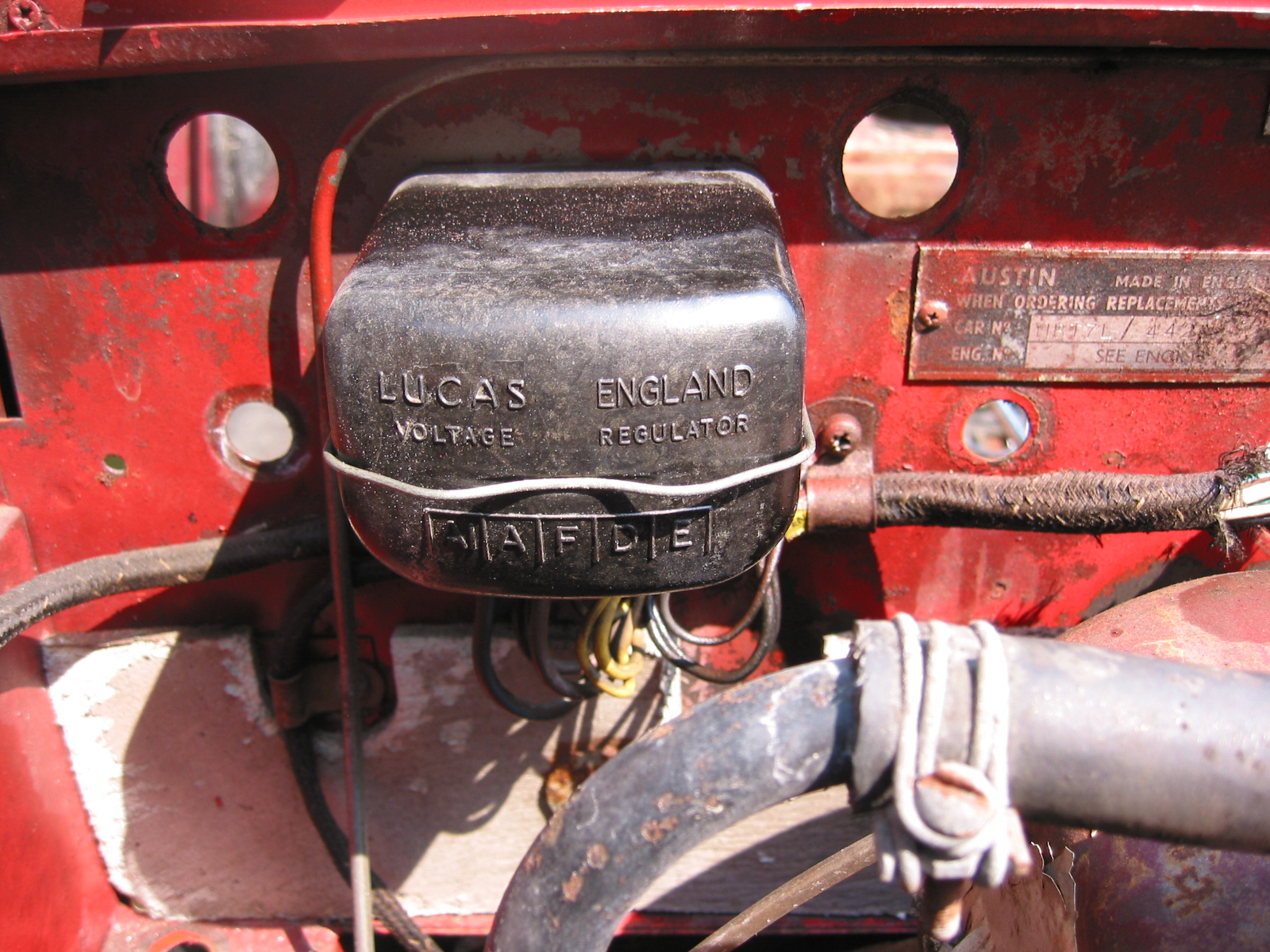
Number Identification Plates – from the firewall. Both are secured with small chrome sheet metal screws.
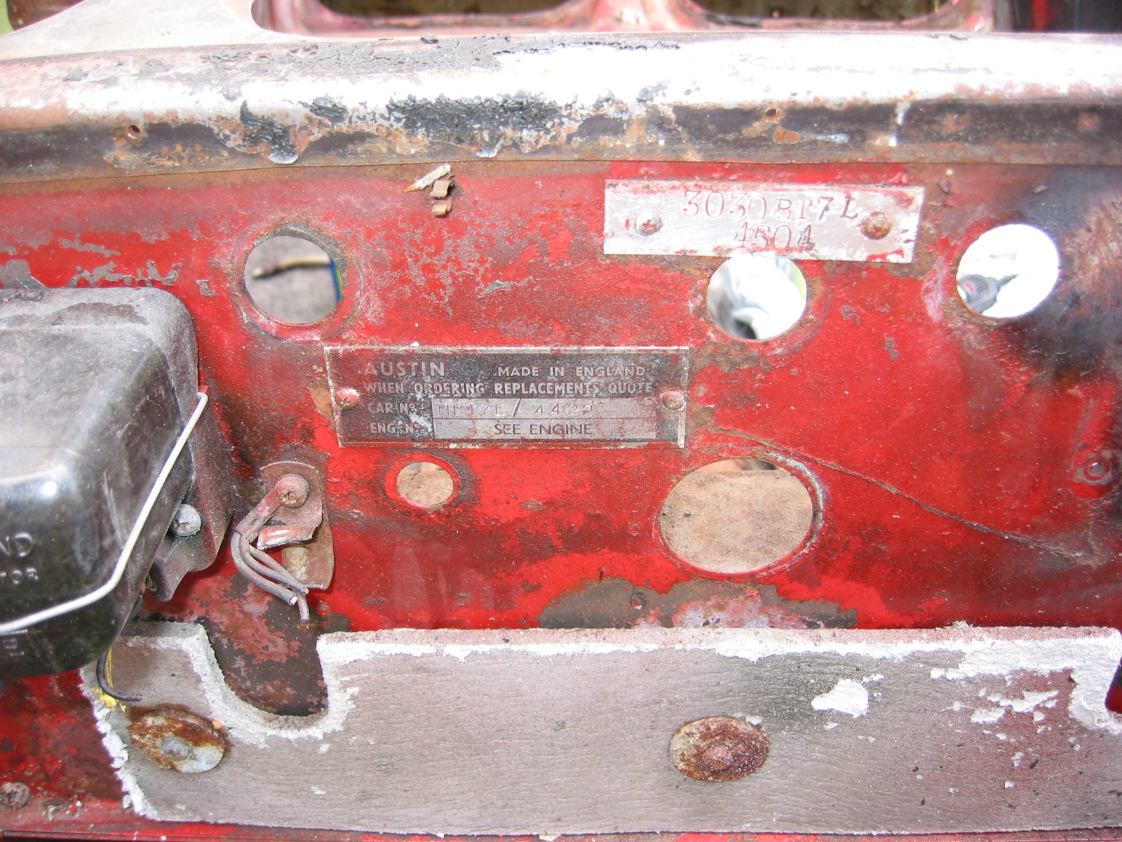
ID Plates 3
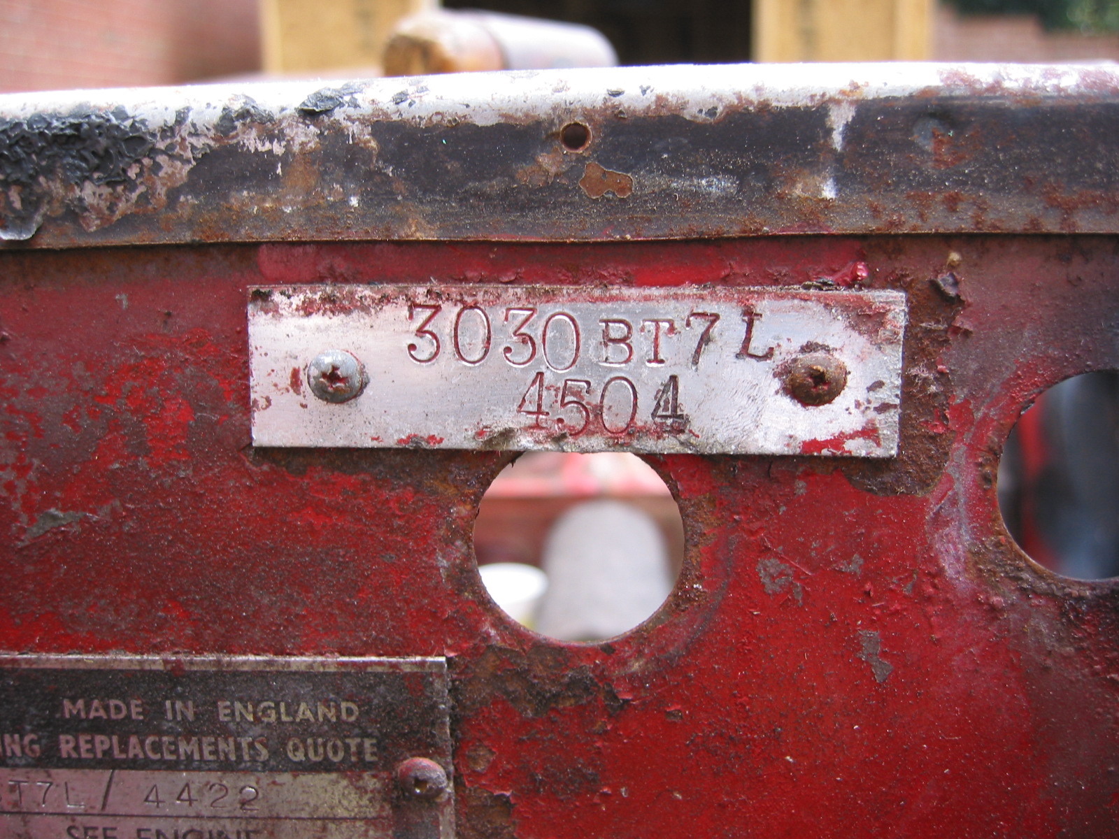
ID Plate 1
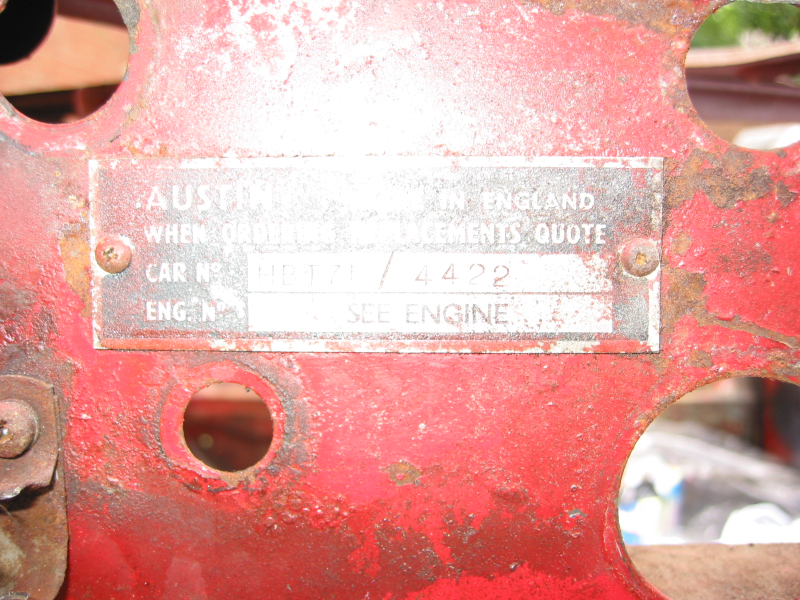
ID Plate 2
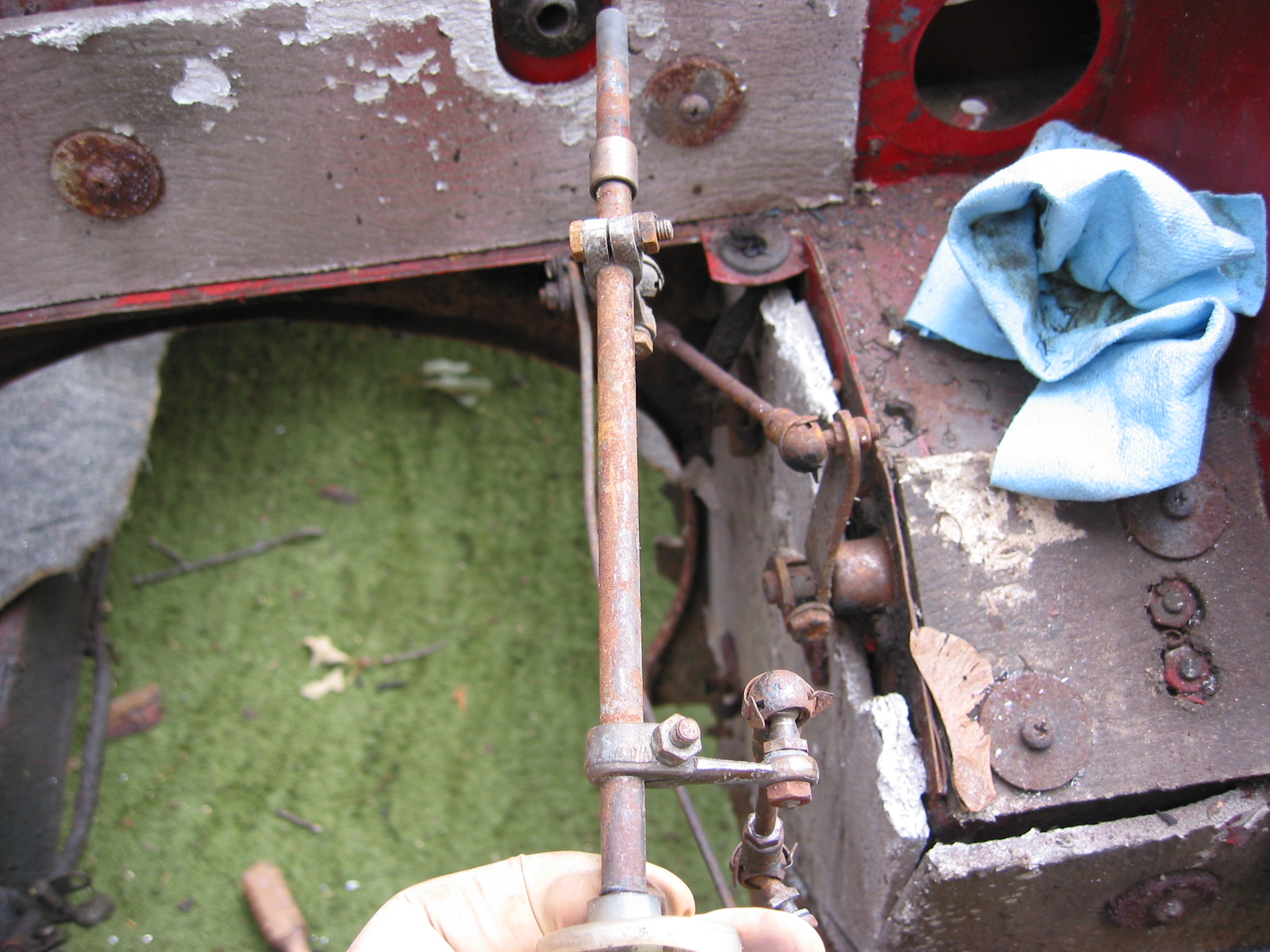
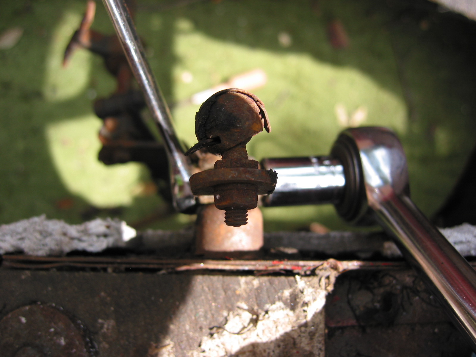
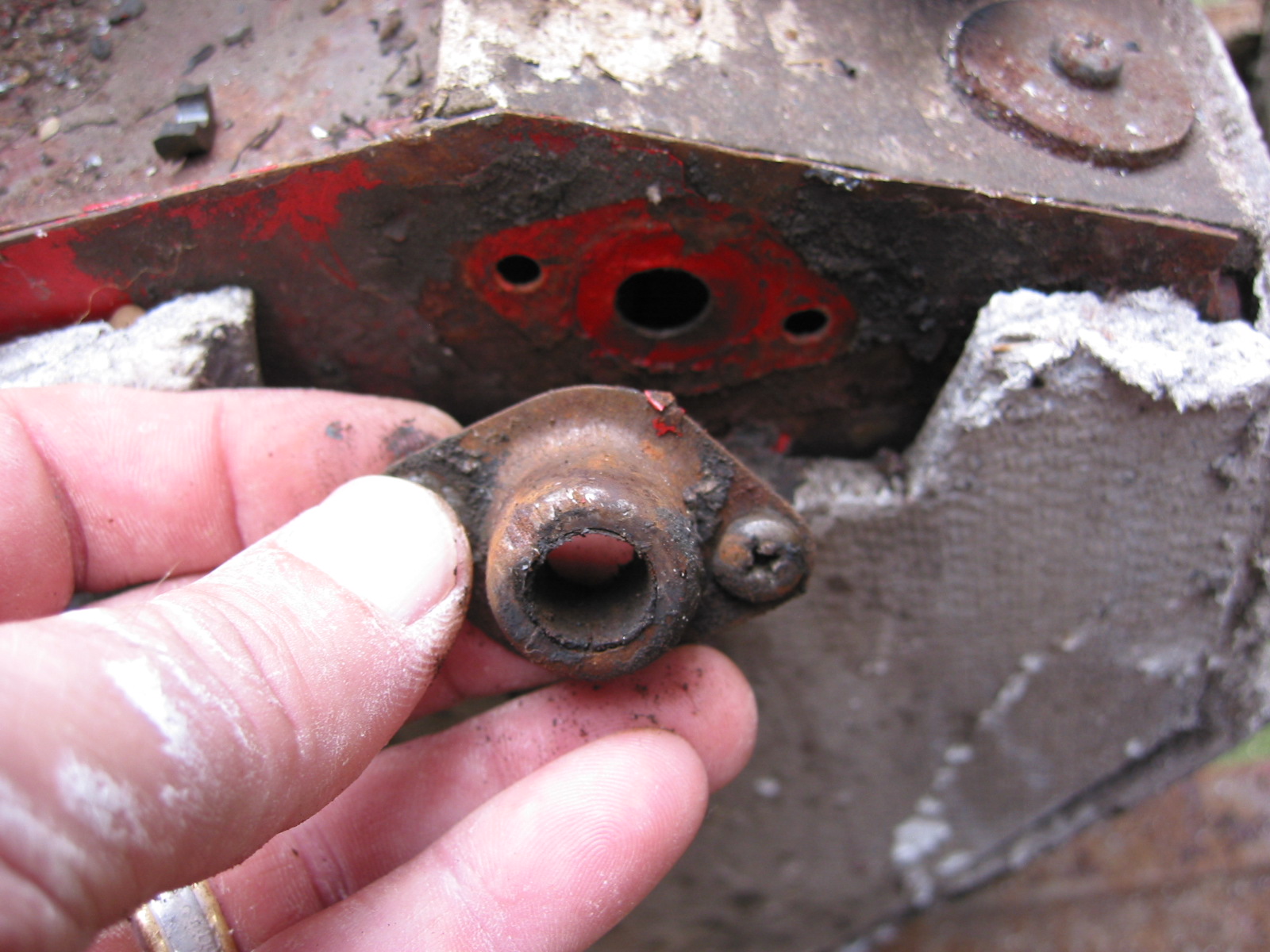
Throttle Linkage – Four 7/16” bolts holding shaft under tunnel. Very hard to get to. Disconnect at pedal linkage. Remove accelerator pedal – two large pozi-drive screws. Remove throttle shaft locator collar from engine compartment wall, two screws and nuts.

Throttle Linkage 1
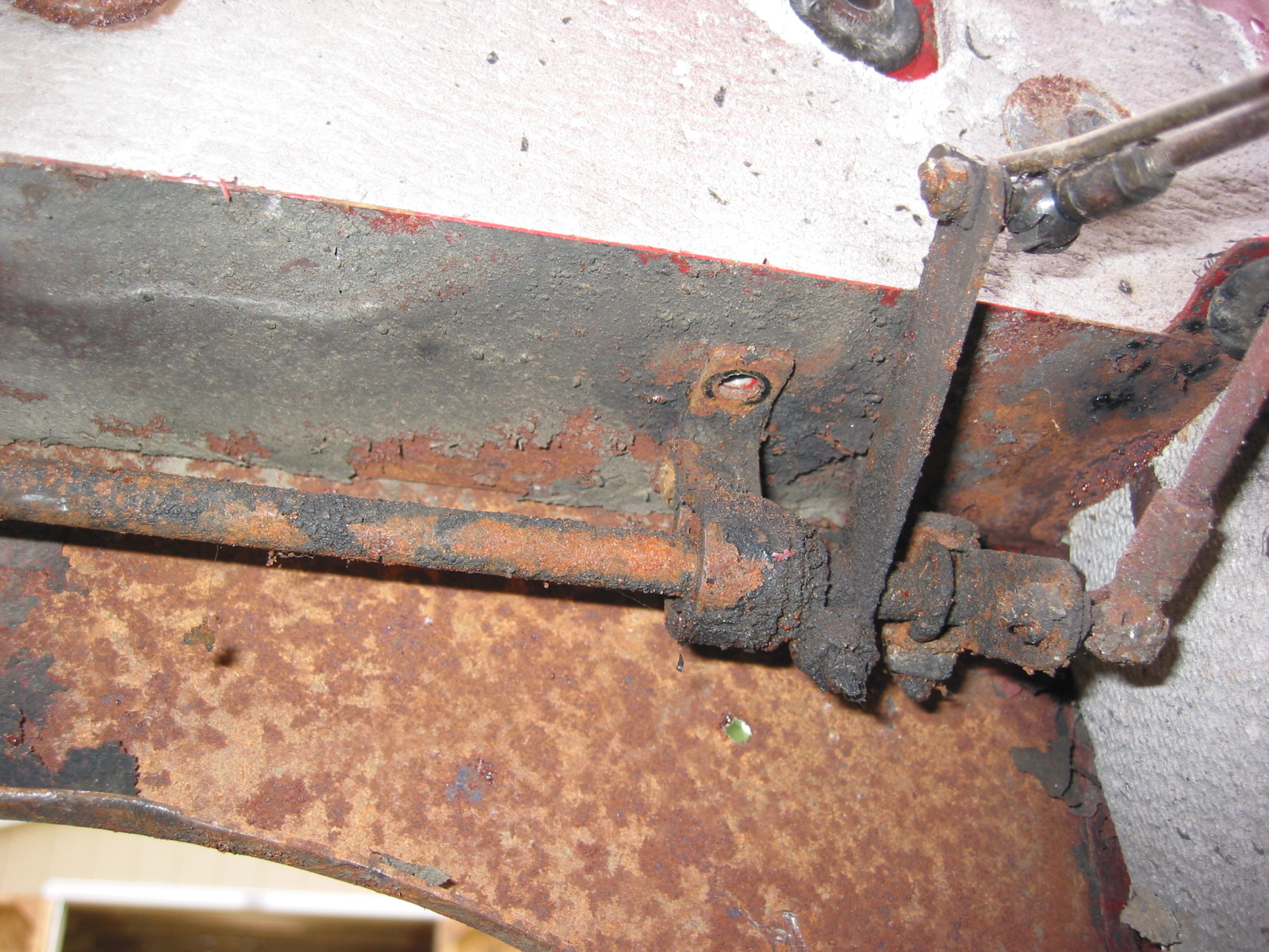
Throttle Linkage 2

Throttle Linkage 3
Throttle Linkage 6
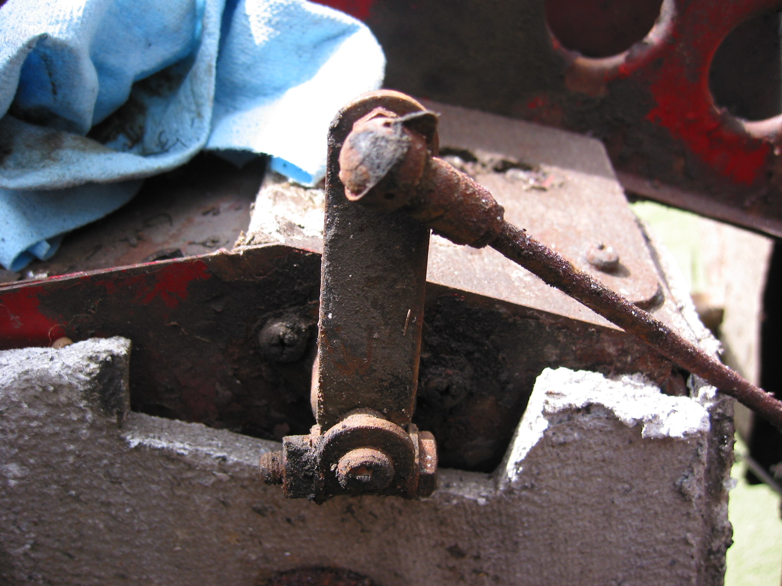
Throttle Linkage 5
Throttle Linkage 4
Throttle Linkage 7
Accelerator collar
Accelerator pedal to firewall