HD8 Carb Initial Tuning

I have read many “how to” documents concerning the tuning of the SU HD8 carburetors including the “Bible” – SU Carburetters Tuning Tips & Techniques

SU Tips

and Des Hamill’s The SU Carburetter High-Performance Manual. But, The summary put together by Steve Byers is about the best single document specifically for HD8 carbs that I have reviewed. Byers Adjustment of the HD8 Carburetor

Steve’s document describes the process of tuning the carbs in layman’s terms in an easy step-by-step process. So, here is what I did:

As Steve indicates, the first thing to do is run the engine until it is at normal running temperature and then begin the tuning process. Of course, in my case, I am making the initial settings before actually operating the vehicle. Following my installation in the car I will do as Steve says and get the car to operating temperature and then I will essentially repeat the tuning steps.

Next I removed the dashpots from the carbs with piston and springs and carefully stored them aside to insure no damage to the needles. At this point I have no oil in the damper tubes. I make sure that I know which assembly is for the front and for the rear carbs – they need to be returned to the proper location.

I then backed off the Fast Idle Adjusting Screw for each carb to ensure that neither screw is touching its throttle shaft stop lever. I cut a strip of paper from a note card to slide between the screw and its stop to test this and to get both the front and rear the same.

Fast Idle Adjusting Screw

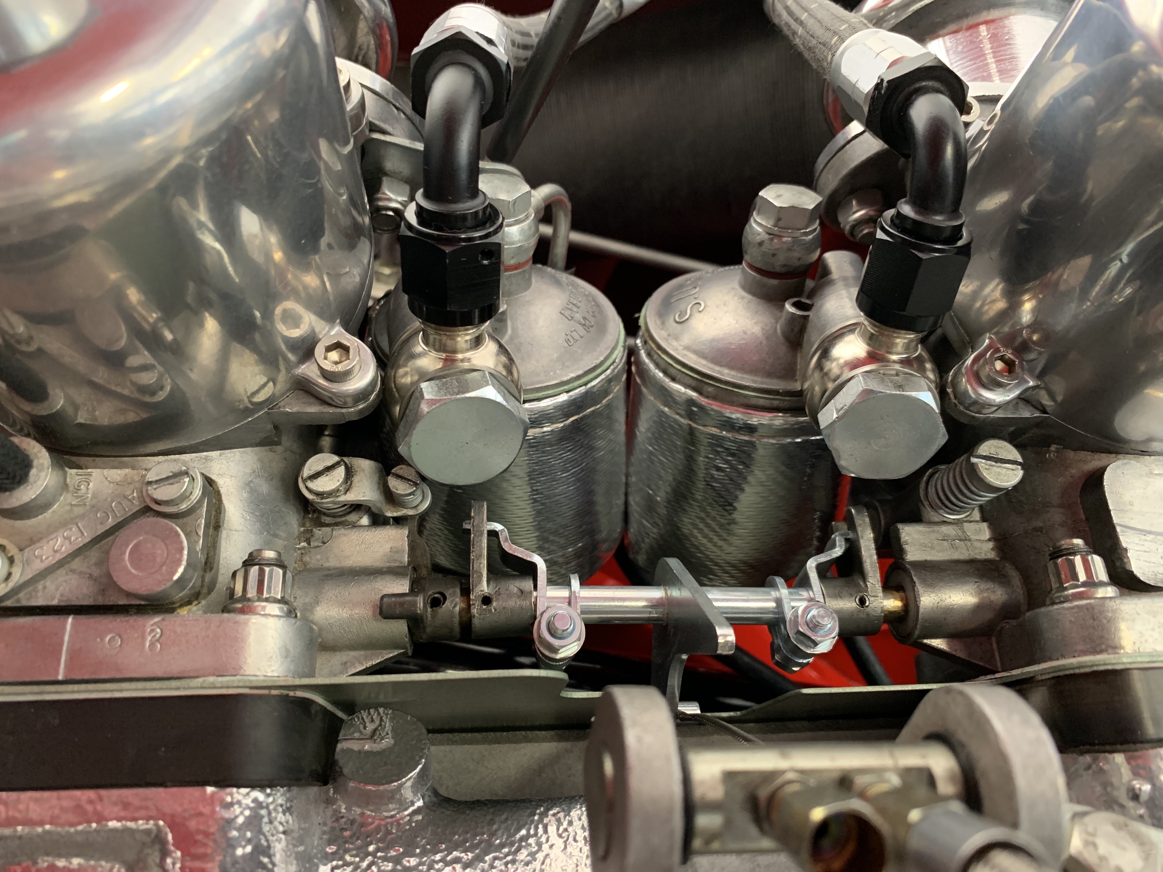
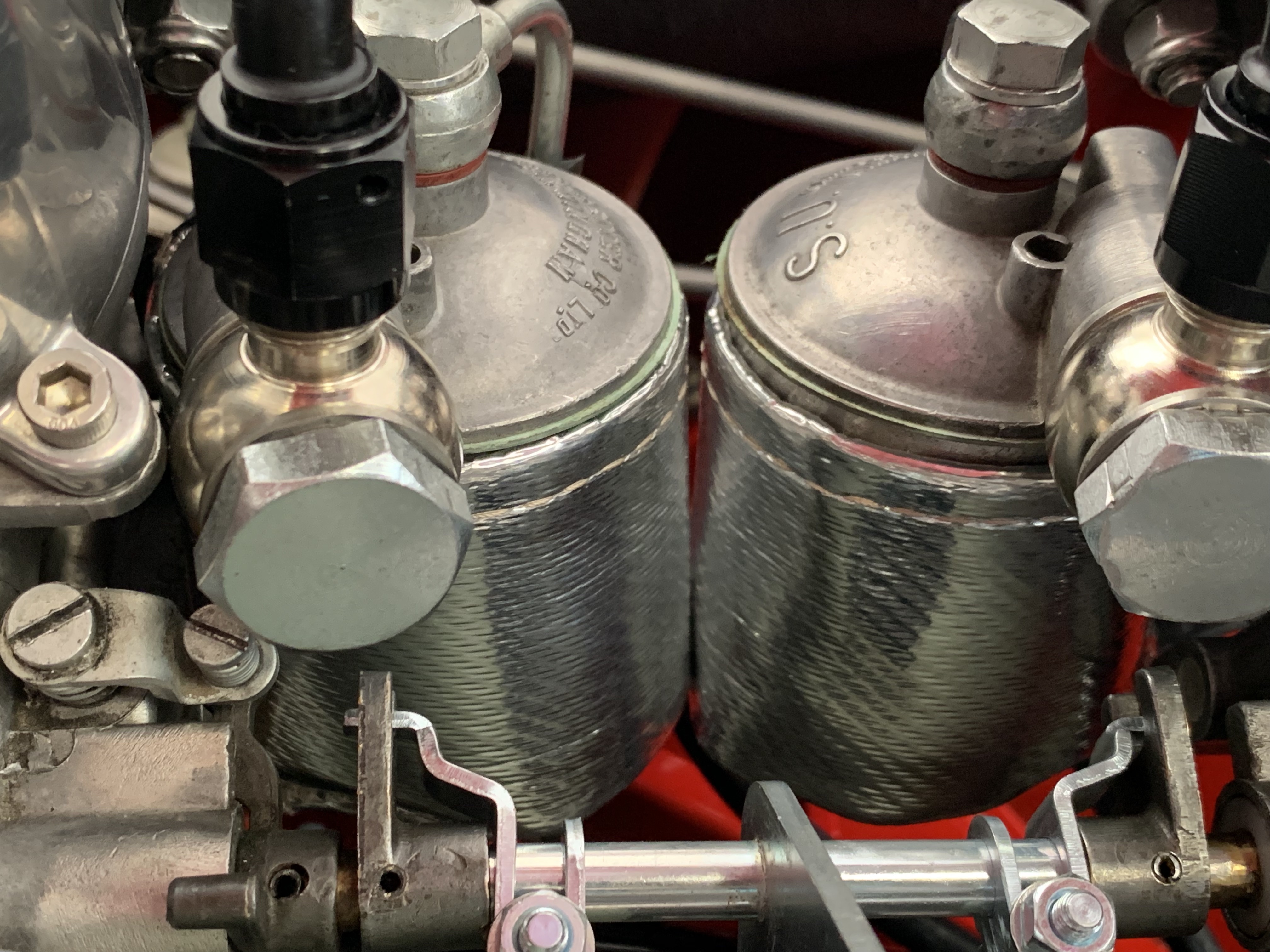
I then loosened the screws/nuts (5/16”) on the interconnecting shaft clamps so that each throttle plate can be rotated independently of the other. I then rotated each throttle plate fully closed by turning its shaft as far as possible. With each throttle plate held fully closed, I re-tightened its shaft clamp screw/nut. Both stops should reach full travel at the same time.

As Steve notes, “There is an extended arm on each interconnecting shaft clamp with a pin that fits into a slot on the carb throttle shaft lever. The pin is smaller in diameter than the slot, so it’s possible to adjust the clearance between the pin and slot (by rotating the clamp) to occur at the upper edge of the slot, at the bottom edge, or both. I adjust mine on both carbs so that most of the clearance occurs at the top. Clearance anywhere except at the top will allow some throttle shaft rotation before the throttle plate begins to open. The SU carburetor manual specifies 0.006 clearance between the bottom of the pin and the edge of the slot, but this is pretty much impossible to measure due to poor access.”

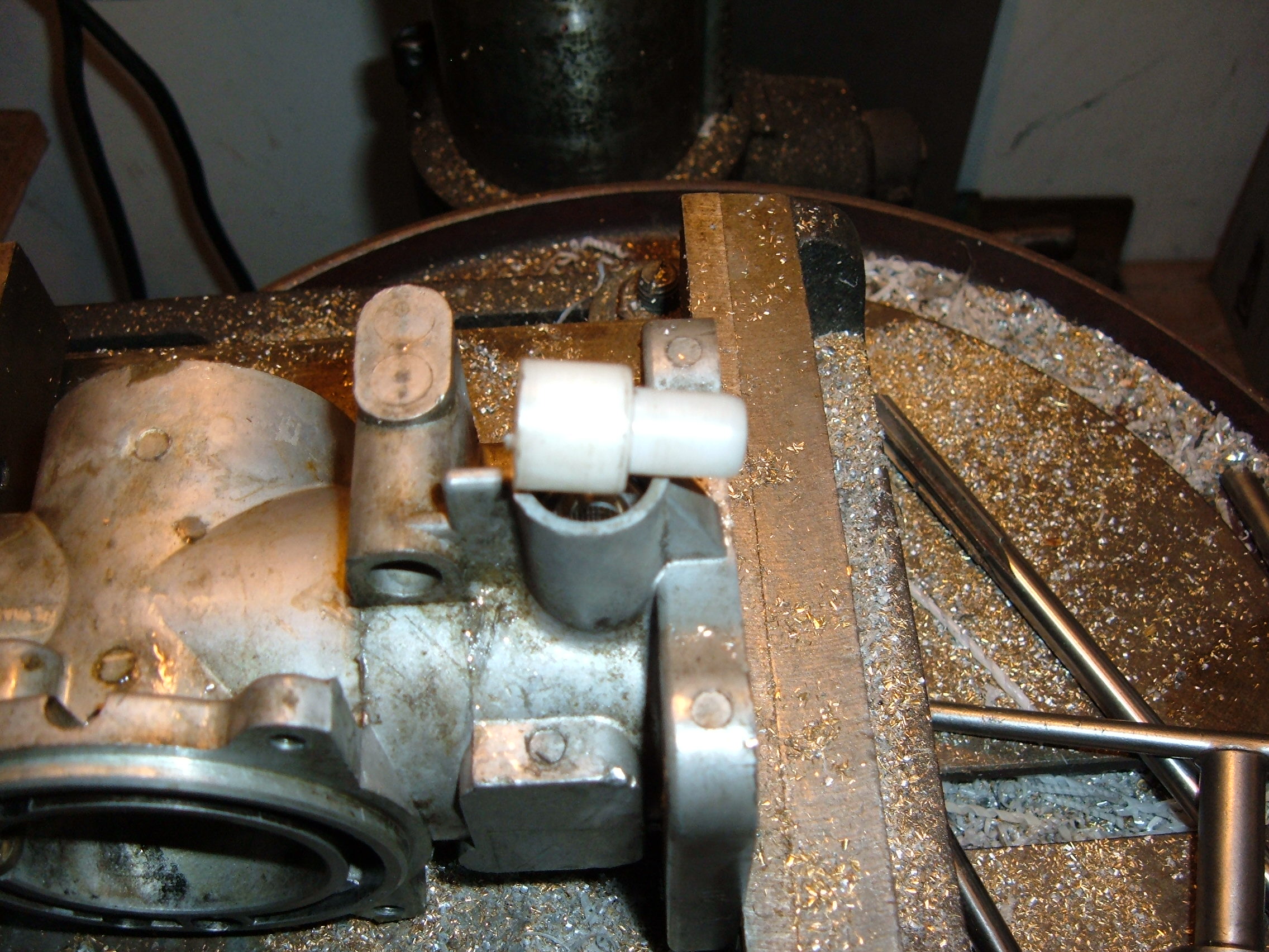
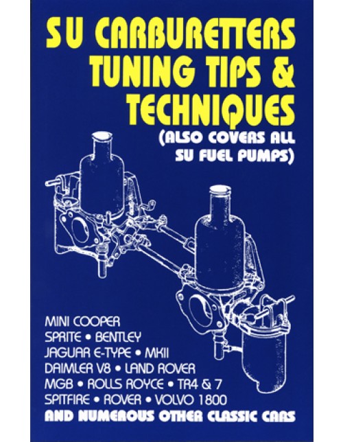
Steve then suggests, using a small straight edge to determine flushness (I use the end of a 6” steel scale), turn the Jet (Mixture) Adjusting Screw for each carburetor until the jet is flush with the bridge of the carburetor (the bridge is the part in the carburetor throat that the piston sits on when it is down). Turn the Jet (Mixture) Adjusting Screw (#2) counterclockwise to raise the jet (leaning), clockwise to lower it (richening).

Jet Adjusting Screw

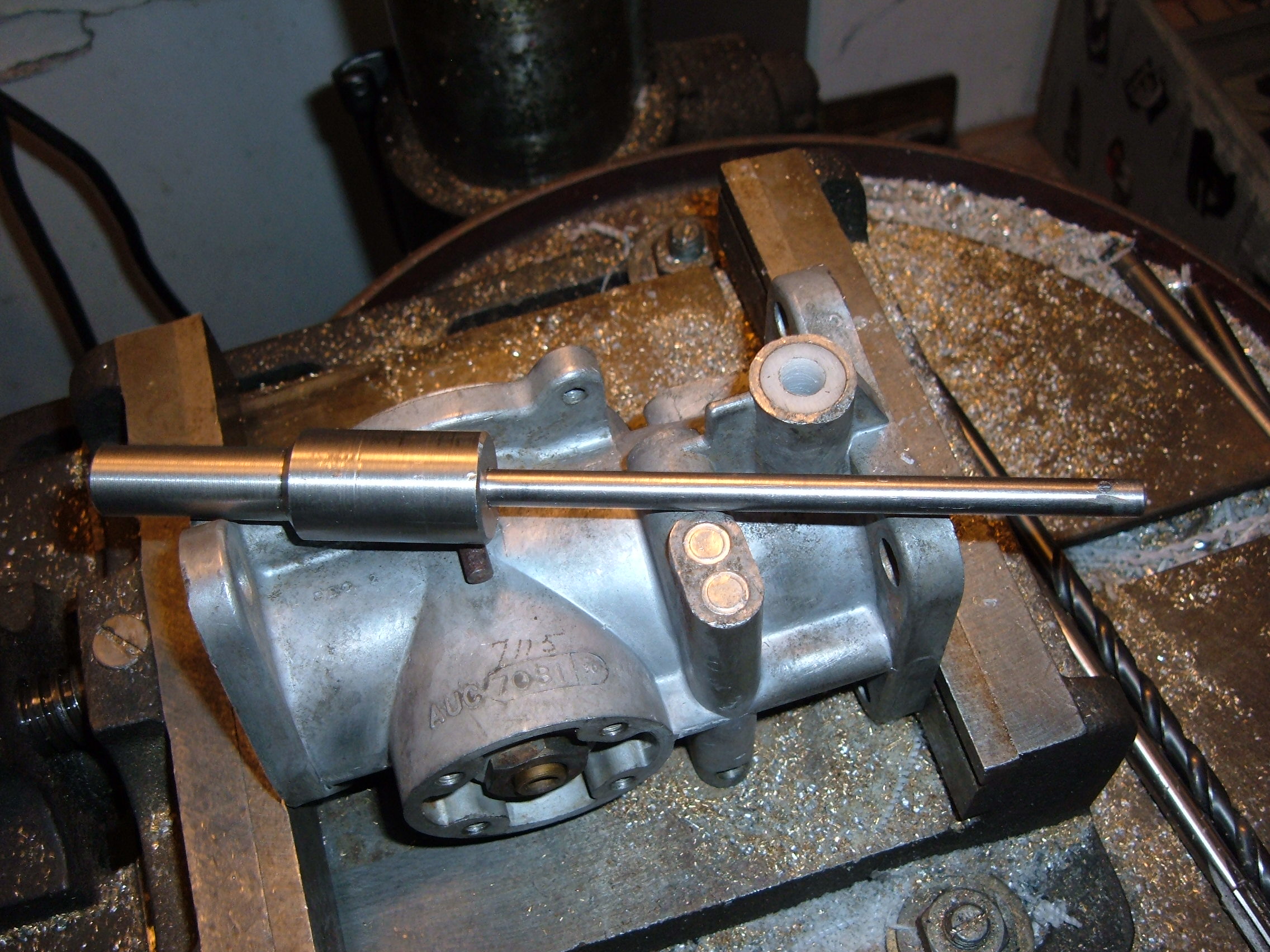
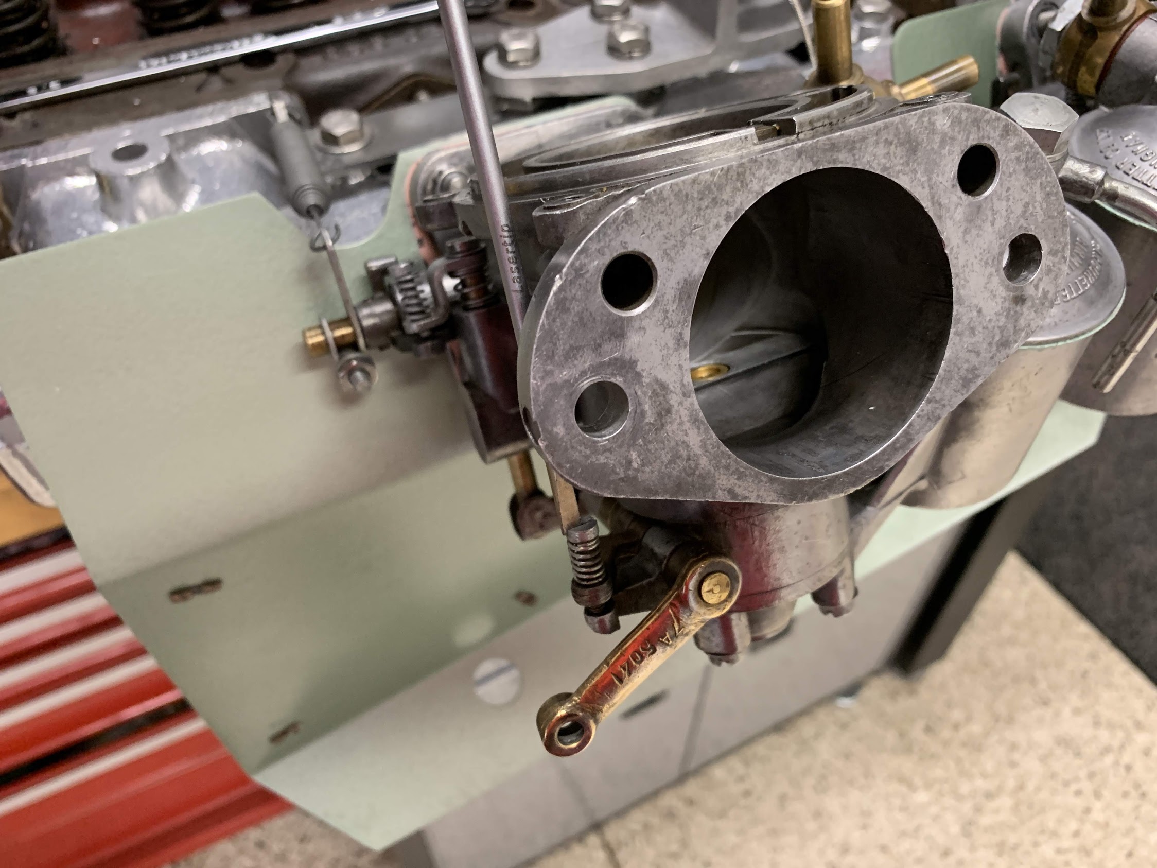
Once the jet is flush, turn the Jet (Mixture) Adjusting Screw three turns clockwise (rich) as an initial setting. Where I depart from Steve just slightly, is that I did not worry so much about the number of turns of the jet adjusting screw. Instead, I use a micrometer to adjust both jets the same amount – .0625″ or 1/16″.

Jet Adjustment with Micrometer

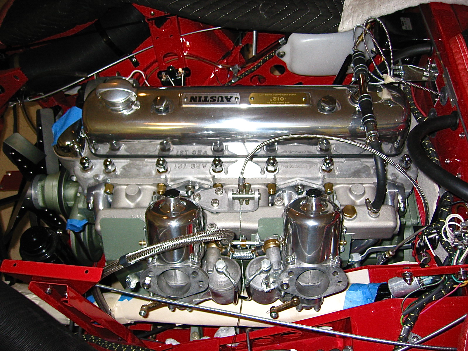
I then re-installed the carburetor pistons, springs and suction chambers.

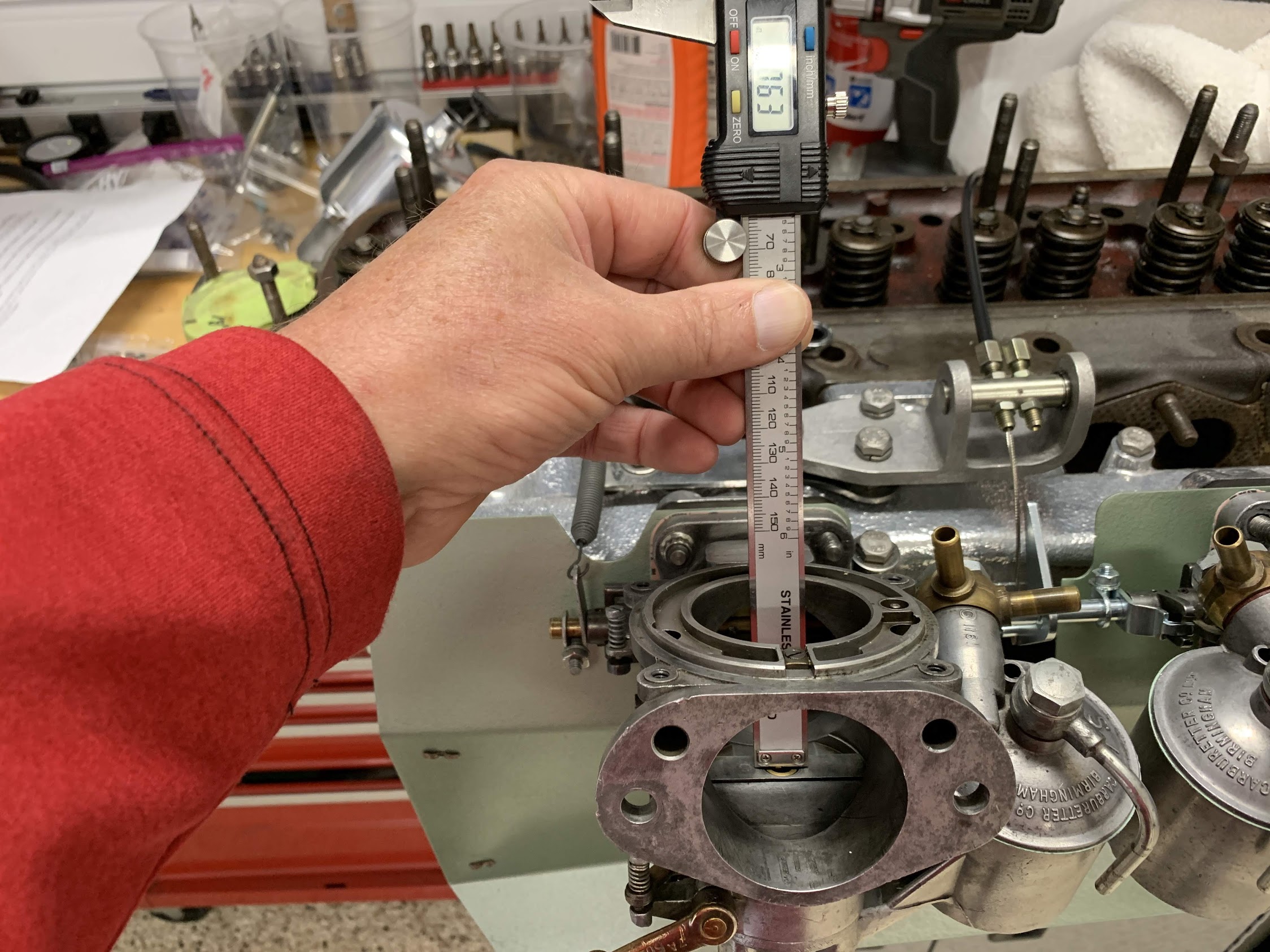
I replaced the original Whitworth screws with number 10–24×9/16 inches stainless socket screws. With a 5/32″ Allen wrench these are much easier to access than the original screws.

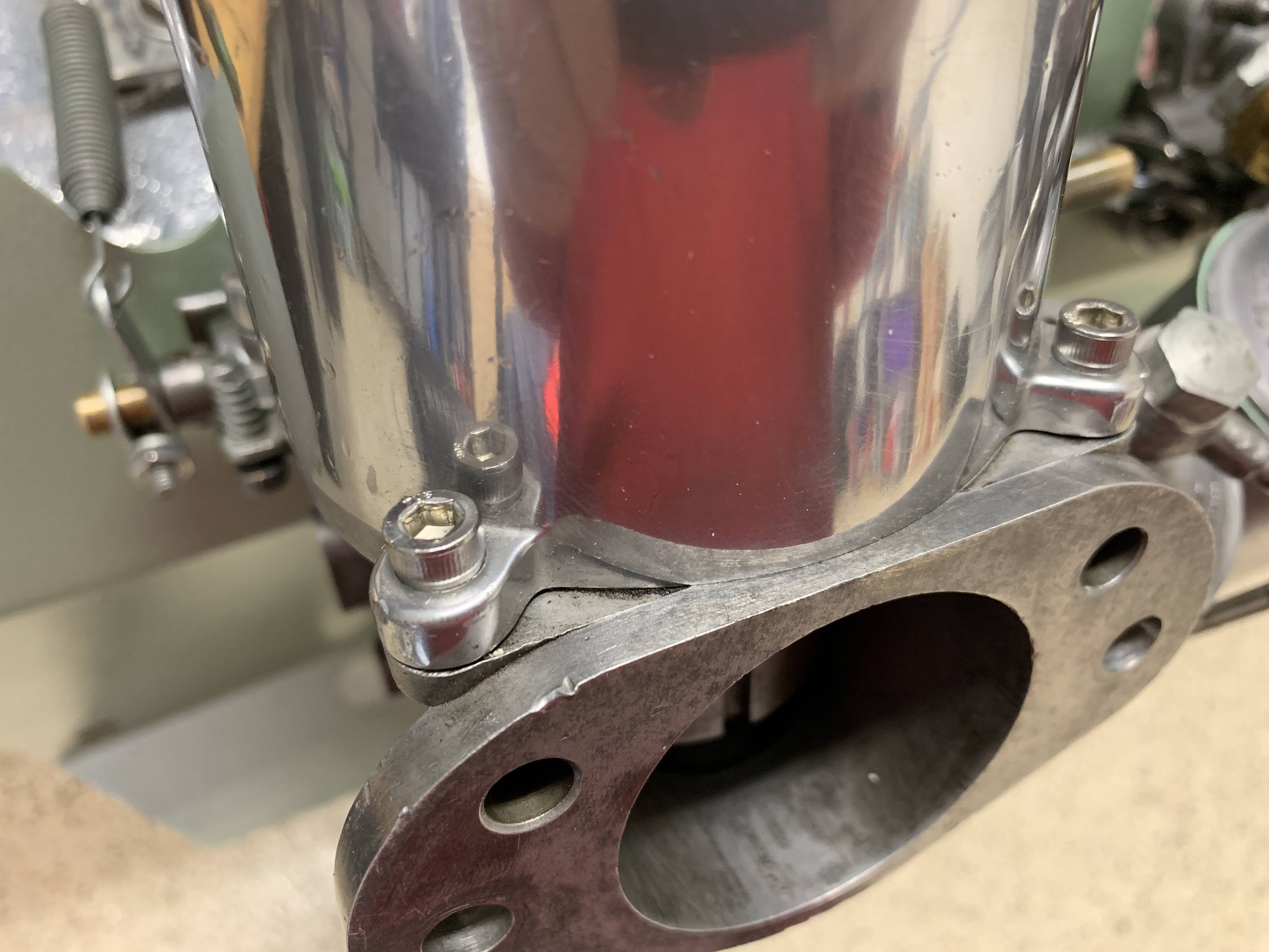
10-24 socket head screws for Dashpots

Again for initial setting, I turned the Slow Run Valve (Slow Idle) Adjusting Screw for each carburetor clockwise as far as it will go until it bottoms lightly on its seat. Then, I turn it back counterclockwise two and one-half turns.

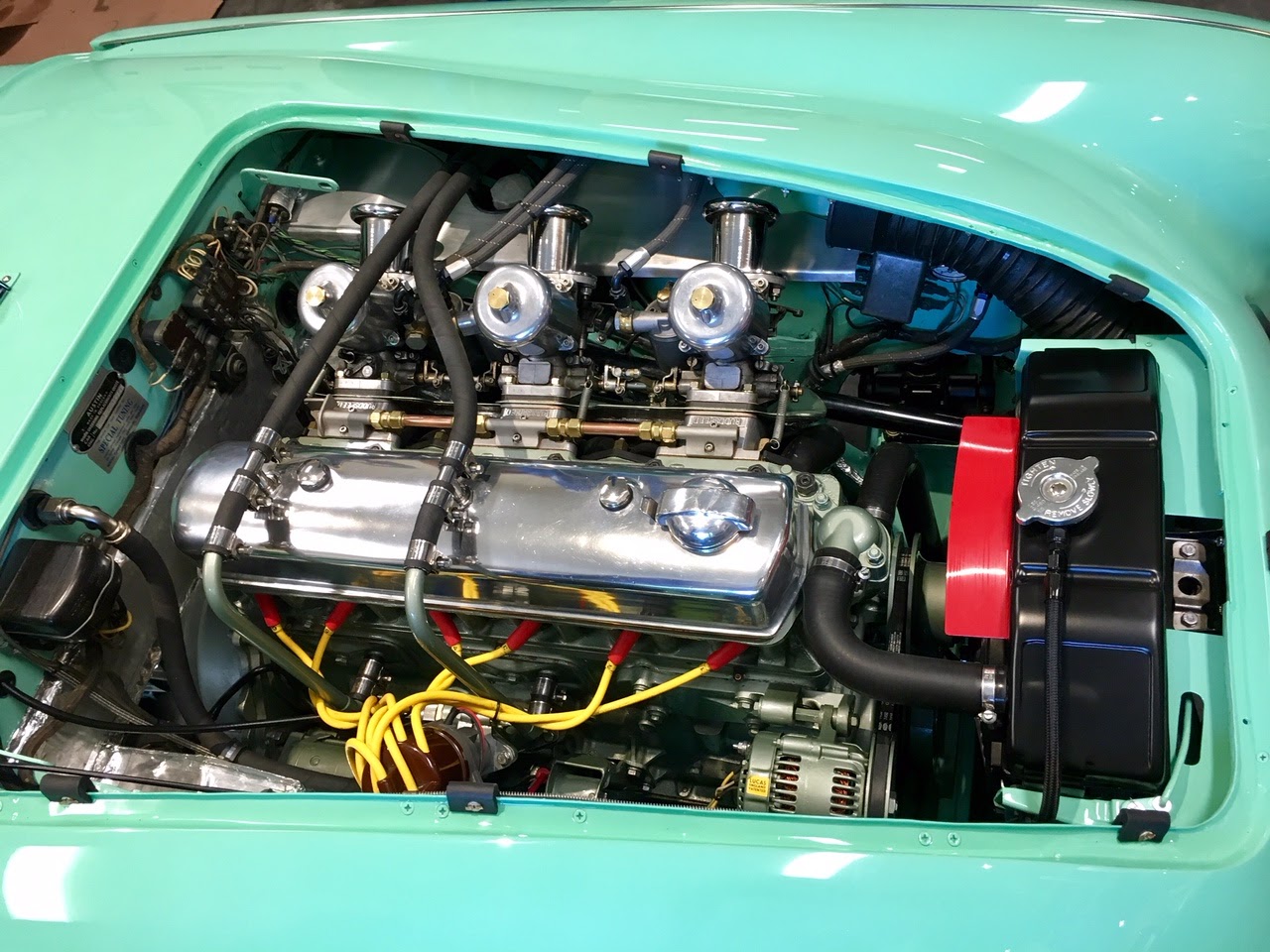
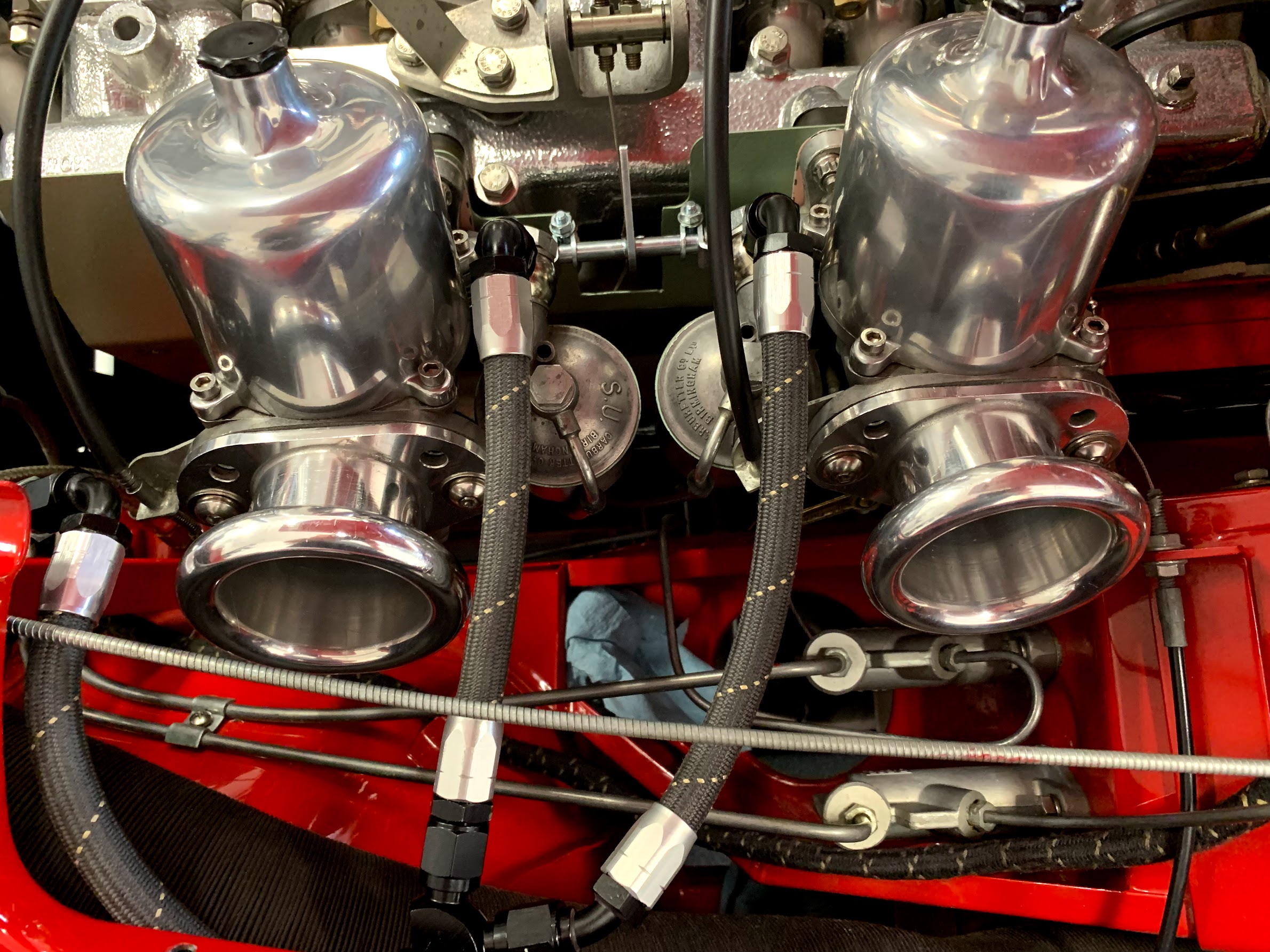
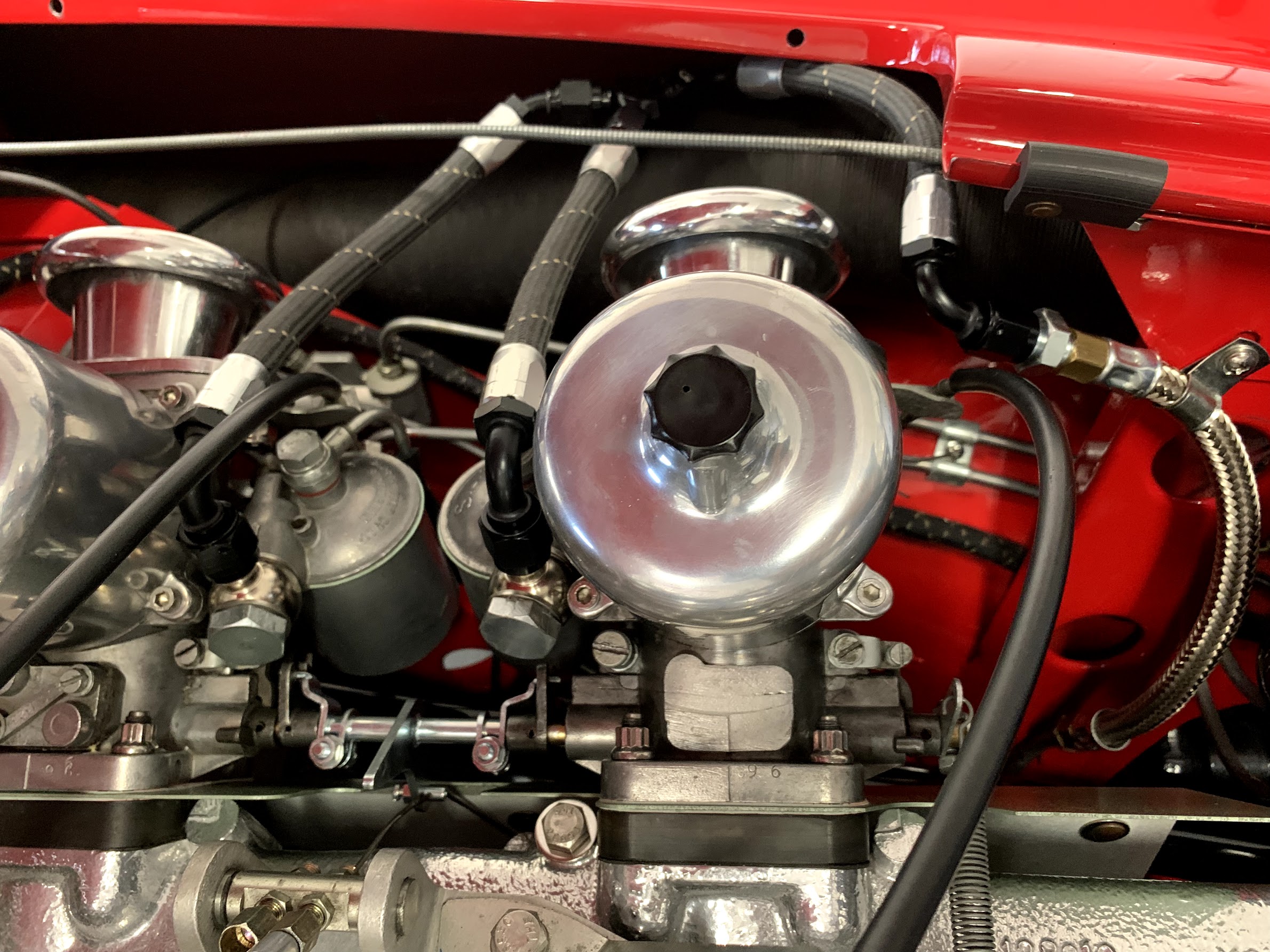
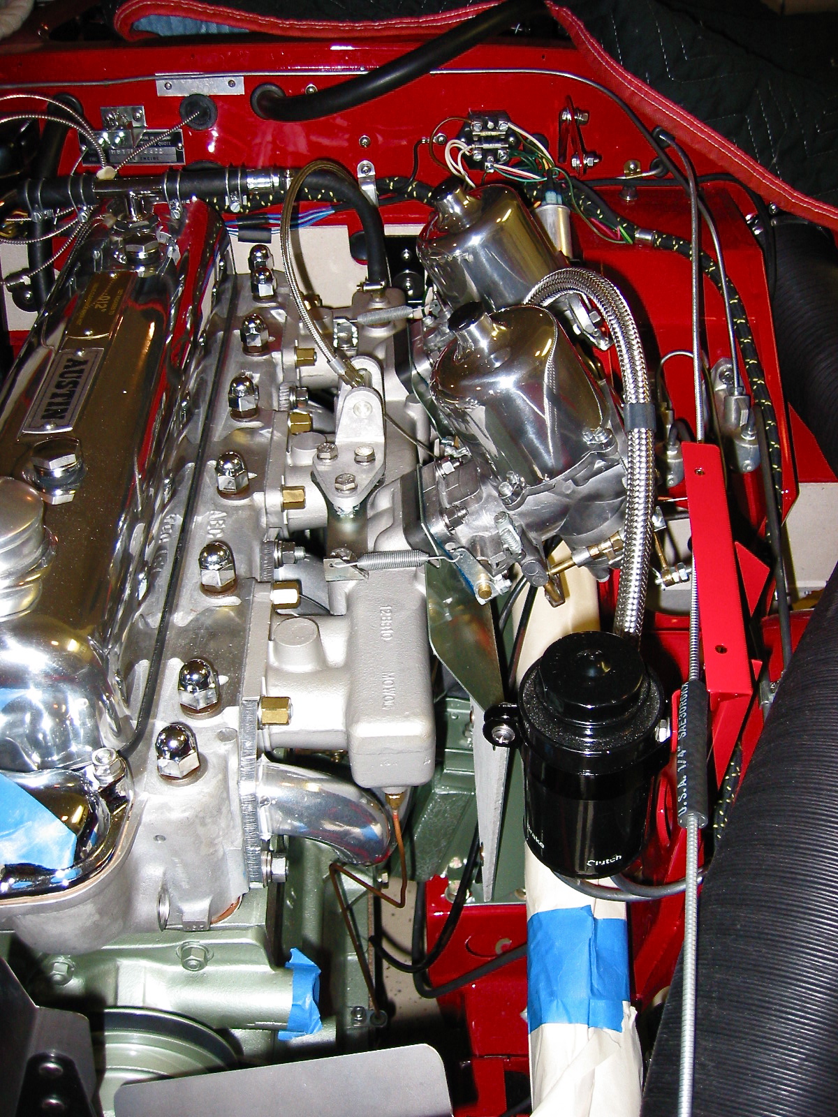
I then installed everything onto the car and assembled all of the components as described here. Once in the car, I reattached the choke cables and their mounting brackets as well as the throttle cable.

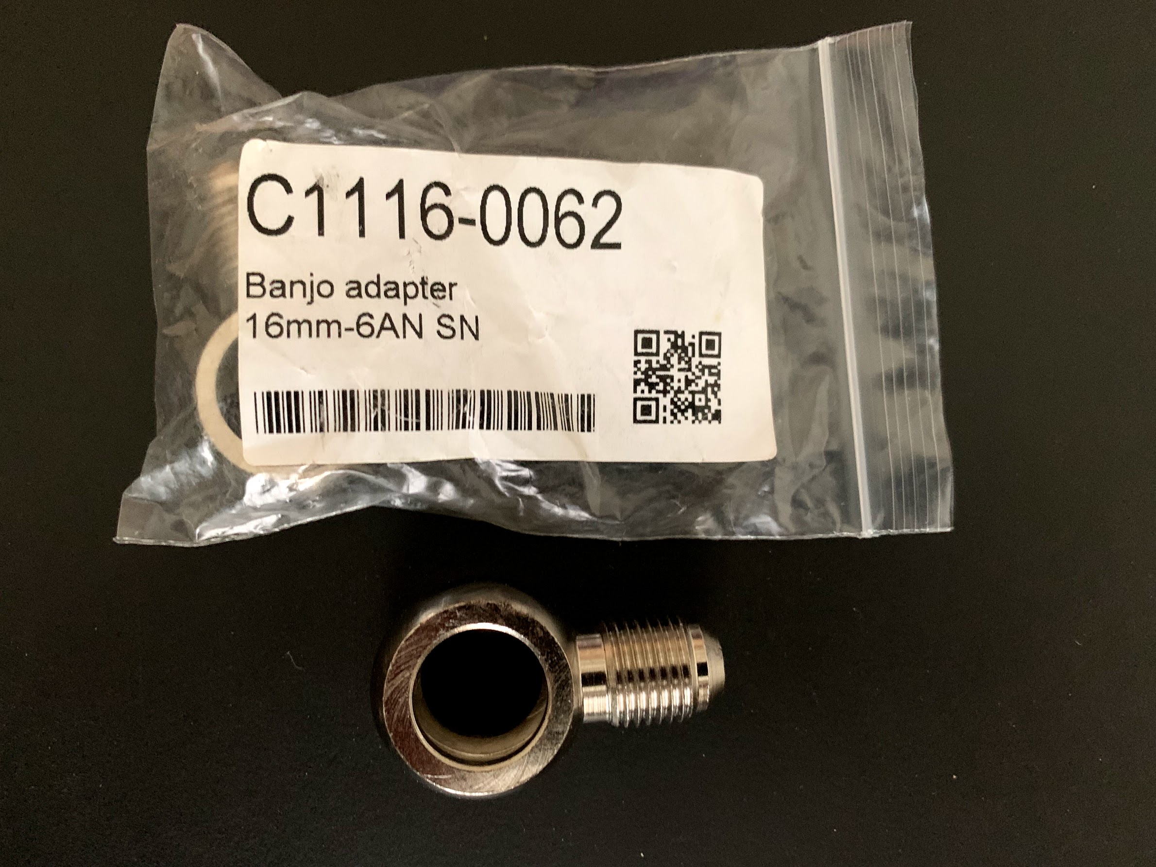
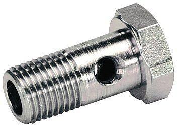
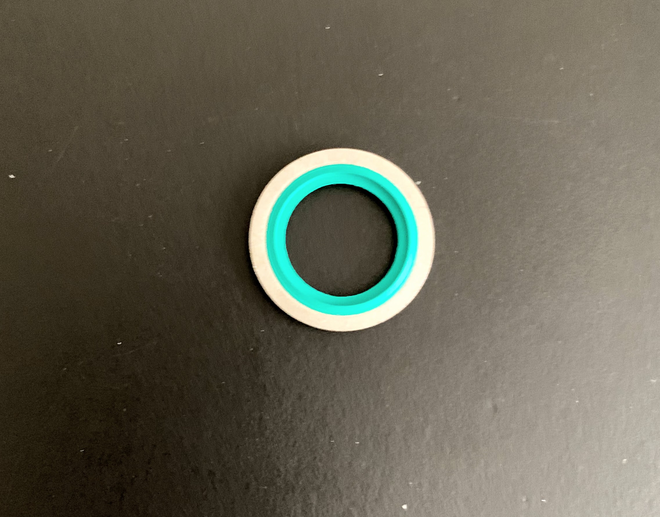
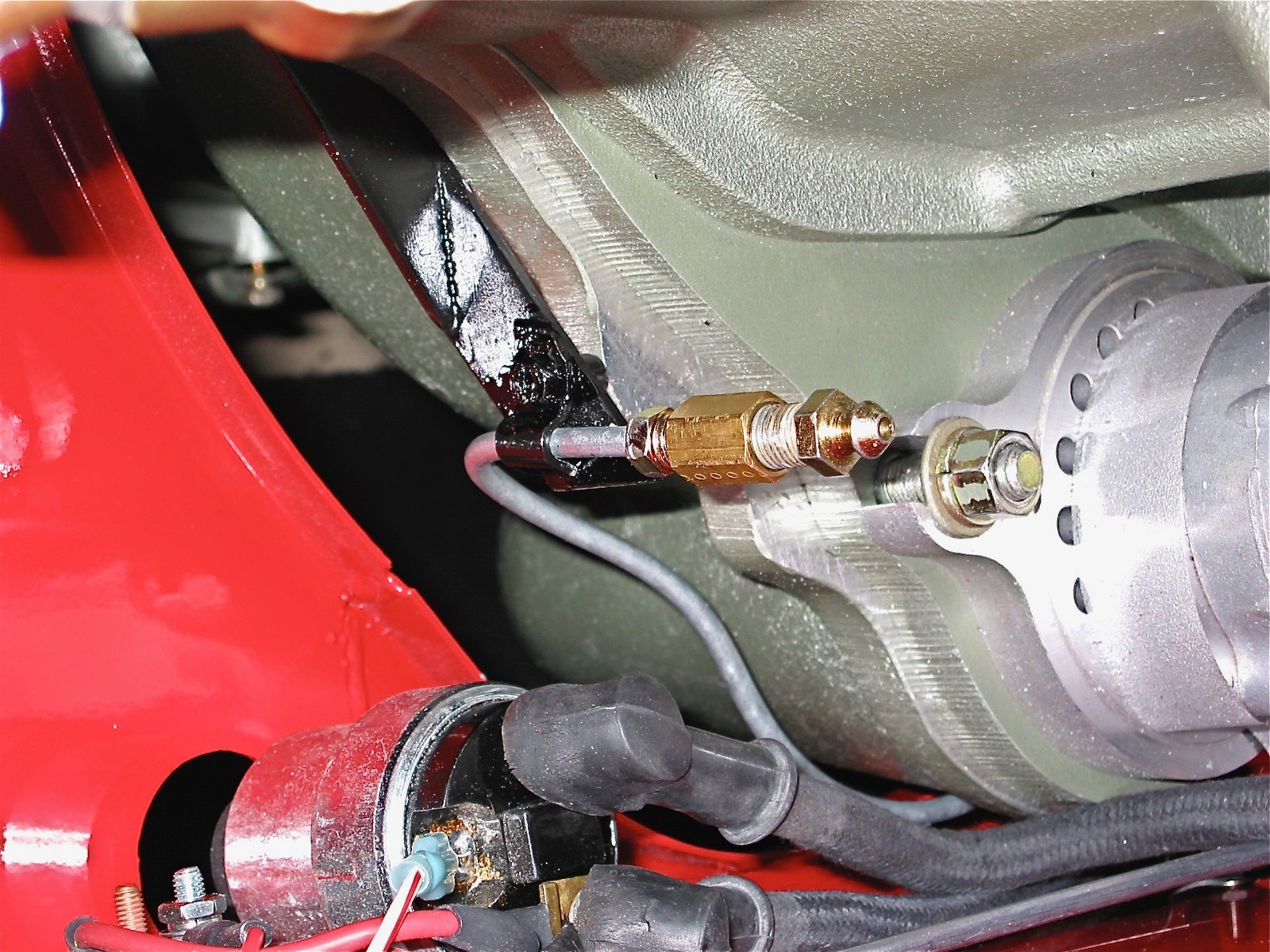
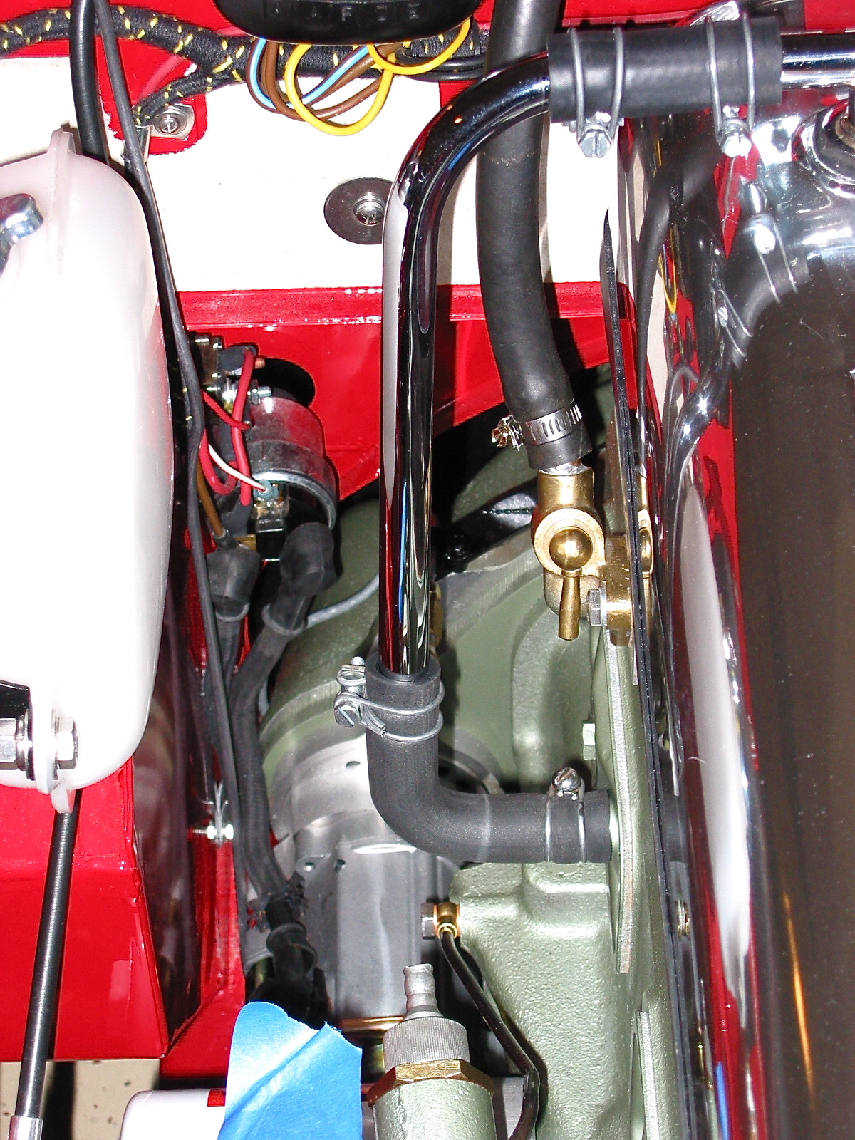
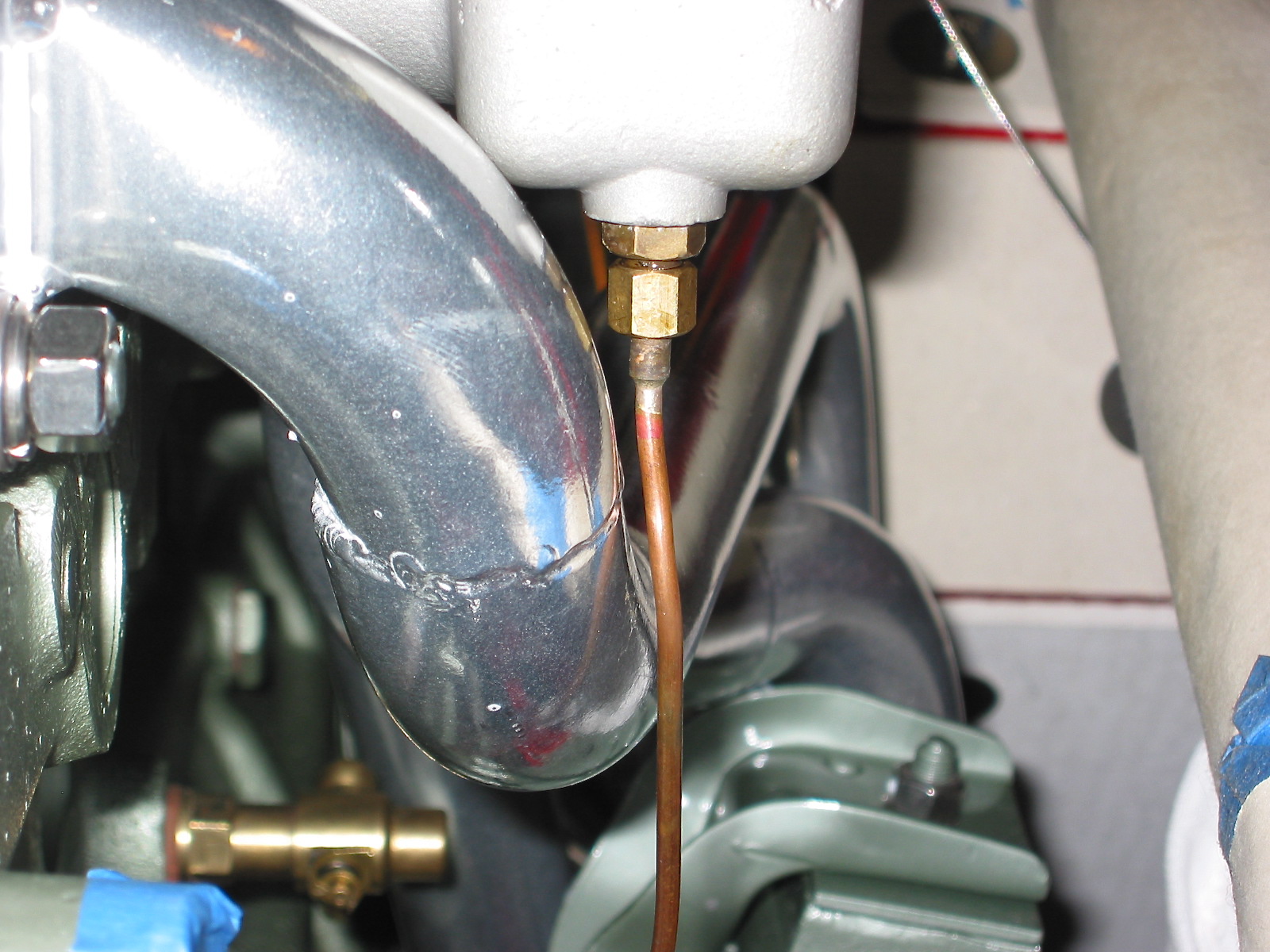
The next step is to install the new fuel delivery system from the hard fuel line coming from the fuel pump up to the carburetors before I can start the car and make final carb adjustments.

HD8 Carb Rebuild

Since I had removed the carbs to install the new intake manifold, I decided it might be a good idea to go ahead and rebuild the carbs. They didn’t have many miles on them, but it has been about eleven years since they were last rebuilt and although I wasn’t experiencing any leaks it seems like a good time to go ahead and replace the bushings, rubber seals and diaphragms.

Joe Curto has done my rebuild work in the past and I was always very happy with Joe’s work. This time I decided to try Thomas Bryant in Wiscasset, Maine. Tom makes and installs delrin bushings for the throttle shafts. Others who have used Tom have indicated that they were very pleased with the performance of the delrin bushings. This is a link to his website and specifically to a rebuild post he did for HD6 SUs. https://thosbryant.wordpress.com/2018/03/03/su-carburetor-rebuild-hd-6/

These are a couple of images from his site that show the delrin bushing:

Delrin Carb Bushing

Delrin Bushing Installed

Tom also checked the throttle shafts for wear (they were OK), replaced the seal for the slow run valve, installed new jets and diaphragms, replaced several gaskets and adjusted the float bowl levers to the 7/16″ prescribed setting.

SU HD Float Lever Setting

I was very pleased with the quality of Tom’s work and his luck turn around. Very easy to work with. I recommend him to others without any hesitation.

This image illustrates the beauty of the bespoke Dennis Welch throttle cable aluminum bracket. The rod running through the bracket is free to rotate which prevents in cable binding when the accelerator is applied. In the image the proper operating angle of the cable is shown:

I also replaced the brass floats in the float bowls with new nitrophyl floats sourced from Moss Motors.

Nitrophyl Carb Floats

Nitrophyl Carb Floats Installed

Preventing Vapor Lock – Float Bowl Kouzies

The summer temps in southern Florida get pretty high and I have experienced a few episodes of vapor lock. Joe Curto who is well know as an SU carb guru sells some covers or “kouzies” for the car float bowls to help prevent boiling the fuel in the bowls. The “kouzies are made from “Koolmat” insulation material and are secured to the bowls with stitched velcro. Joe’s site indicates that the material offers continuous temperature protection to 650 degrees F and short term thermal exposure to 1000 degrees F. “Koolmat” claims to reflect 90% of radiant heat energy.

The covers are well made and fit nicely. Now, time will tell if they solve the vapor lock problem!

Curto Koolmat Kouzie

Joe Curto Float Bowl Cover

Kouzies Installed

Curto Kouzies Installed

Fuel Delivery Modification and Ram Pipes 

This project actually began back in November and took me till Spring to complete! I was inspired by Doug Escriva’s beautiful engine bay on his even more beautiful Healey racer:

Doug Escriva’s Racer

Doug Escriva’s Engine

I especially liked Doug’s fuel delivery system to the carbs. Of course, Doug’s car is a tri-carb while mine has only two HD8 SUs. I was never fond of the original fuel delivery design in which the fuel hose fed to the front carb banjo with a second feed off that banjo to the rear carb via a 2″ piece of hose. I also liked the idea of getting rid of the required fuel hose screw clamps and changing to AN fittings. Finally, I am a sucker for the look of the air horns on the SUs. Since I live in Florida where it is sandy, I will use some socks over the horns for normal driving to protect the intake ingesting some unwanted silica. While these modifications appeared easy to accomplish, as it turned out it was quite a chore to find the necessary fittings. Hence the long elapsed time from concept to completion. 

Before getting into the components required for the new system, I also need to mention that my Healey friend, Randy Forbes, who is now geographically close since we have relocated to Florida, was also a big help in making some modifications to the components.

These two photos show the new fuel lines, the fuel fittings and the “Y” Fuel Block installed:

Modified Fuel Delivery System and Ram Pipes

Modified Fuel Delivery System with Y Fuel Block

Modified Fuel Delivery Hose and Fittings

I replaced the original brass banjos on each carb with Steel 16mm M16 5/8″ 6AN Banjo Adapters with short necks, part #C1116-0062. These were difficult to find but I ultimately located them on EBay. The seller’s name was smartturboisme.

Banjo Adapter 16mm -6AN C1116-0062 EBAY

These were slightly wider than the original brass banjos requiring new banjo bolts. These were also difficult to source. I eventually located these 3/8″ BSP banjo bolts from AgriStore USA. They were 1 1/2″ long with four fuel flow holes. They were slightly too long to fit snuggly in the SU float bowl caps so Randy Forbes cut them down slightly. While the threaded portion of the bolts fit through the new banjos, the grip portion of the bolts would not so Randy also took a few thousands off the grips.

3/8 BSP Banjo Bolt

I purchased Viton sealing washers for the banjos and the bolts. These were sold by Hydraulic Fittings, part #9500-06V Bonded Seal, 3/8″BSPP (Viton). 2 were required for each carburetor.

3/8 BSPP Viton Seal Washer

I installed a new, as original, petroflex fuel line which connects to the fuel hard line running from the fuel pump to the engine bay. This hose is part #FUL062 from Healey Surgeons. A 90 degree 811 Aluminum hose end #3481-06 was then screwed into to the upper end of the petroflex fuel line. The hose ends were sourced from Pegasus Auto Racing Supplies

Aluminum Hose Ends

A short piece of racing fuel hose, 910 PTFE Lined Aramid Braided Lightweight -6 from Pegasus was used to connect the 90 degree fitting from the petroflex hose to a straight fitting which then screwed into a “Y” fuel block.

910 PTFE Lined Aramid Braided Lightweight Racing Hose

The fuel block has a single inlet and two outlets, all 6AN. The fuel block was made by Russell and sourced from Jegs part #799-650430.

Russell Billet Aluminum Y-Block -6 AN Male Single Inlet

One straight and one 45 degree aluminum hose end was used to connect the outlets of the fuel block to two 90 degree aluminum hose ends at each carb banjo. All of the fittings and hose connections proved to be tight and leak free when tested. I am very pleased with the functional and esthetic enhancement to the stock fuel delivery system. 

I purchased the 2″ polished aluminum ram pipes from Doug Escriva as well as pair of ITG Megaflow JSC-12 Air Socks.

ITG JSC-12 Megaflow Air Socks

Chapter 79 Week Forty-Nine November, 19 2007


I am now waiting on Jack Harper to get free from his shop duties at Coachworks to come by the house and help me with starting and tuning the engine. While waiting, I took a few moments to check on 
sealing the firewall from fumes and heat emitted from the engine bay. I turned off the the lights in the garage and put a shop light in the engine bay and then inspected the firewall for any light coming through the firewall. As expected, I did find a few places, so I used a little 3M body caulk to seal the holes.

Another variance from originality on my project is the “personalized” arm rest. Its standard location makes it virtually useless as a functioning arm rest while driving. I am going to make a wooden box to fit the arm rest pad sourced from Heritage Upholstery and Trim to serve as a storage console and to lift the height of the pad to make it work as an arm rest while driving. I will cover the box with matching black carpet and hinge it at the rear of the pad. To begin my little project, I made a mock-up of the box from a cardboard shoebox. For me, 2 3/4” appeared to be the proper height of the box, with the cushion on top of the box.

Arm Rest Prototype

Jack Harper came over to the house and we readied the engine for starting. First, we connected the cables for the throttle and choke. While the previous injection of oil through the engine should have sufficiently lubricated everything, I still pulled the spark plugs and turned the engine with the starter until the gauge showed oil pressure. I put 5 gallons of fuel in the tank and we turned on the ignition to try out the fuel pump. The carb float chambersfilled and we were then ready to try firing up the Bloody Beast.

We reinstalled the spark plugs, turned on the ignition and hit the starter button. After about 10 seconds we had the engine running! Jack ran the engine up between 2,000 and 2,500 rpms and then we adjusted the carbs to bring the idle down to about 700. After 30 years another Healey is saved and running. It was an exciting moment.

I did have two problems to be fixed. I had taken apart the hot water valve, cleaned it, reassembled and installed it on the engine. It leaked! So I ordered a new one to replace the original. The second problem was my own stupidity! I did not replace the  Toyota gearbox real oil seal and I quickly discovered that I should have as a pool of MT-90 formed under the car. New seal ordered also. Cannot wait to get both pieces, install them, and get her running again!

Chapter 74 Week Forty-Four October 15, 2007

With the engine in place, it was now time to complete the assembly of the various engine components, but first I installed the clutch slave cylinder with the push rod provided in the Smitty conversion kit. It went in without any problem and lined up perfectly. The clutch pedal seemed to work smoothly. The bleeder extension pipe was attached to the bracket I made to support the pipe. Bleeding the slave cylinder will now be a much easier job. Thanks again to Mr. Finespanner – Doug Reid.

Slave cylinder bleeder extension 2

Just to fill the holes and to prevent anything from dropping in unexpectedly I went ahead and loosely fit the NGK Spark Plugs BP6ES, stock number 7333.

To make installation a little easier I attached the gear reduction starter to the engine prior to installation in the car, and it was now time to hook up the wiring. I shortened the heavy duty starter cable that connects the solenoid and the starter and secured it to the starter with rubber insulation boots attached. Since my intention is to still rely on the original starting configuration, that is, using the external solenoid, I connected the small wire on the starter to the terminal post also used to connect the cable from the solenoid.

Starter

The installation of the breather pipe and hoses was next on my list. Since I will be taking off the rocker cover for valve gap adjustment once the engine is started, I left the clamp to the “T” connection on the cover loose. The inlet heater hose from the heater to the heater control tap on the motor. While in that location I went ahead and connected the tachometer cable to the tach drive housing.

Breather Pipe 2

Tach Cable to Drive Gear

Others have suggested the addition of a PCV valve connecting the breather “T” to the intake manifold to assist in minimizing oil pressure leaks. I bought a little kit from the British Car Specialists that included the valve, rubber piping and a connector for the intake manifold. It will be interesting to see if it does aid in respiration.

The oil gauge flexible hose was connected next. It connects to a fitting on the block and to the steel oil line that connects to the back of the oil pressure/water temperature gauge.

Oil Pressure Line


The exhaust headers were next to be installed. These are Phoenix headers and the full big bore exhaust system was sourced from AH Spares. The headers fit perfectly without any adjustments. I had them Jet-Hot coated in the sterling finish to keep them looking nice and to improve thermal qualities. Stainless steel flexible pipe (1 7/8”) was used to connect the headers to the stainless steel silencer and the big bore tail pipes. The front hanger bracket is in the wrong place for a BT7, so I made a custom spacer for that hanger. The rear hanger worked just fine. I was pleased with the final installation of the system.

Headers 1

Headers 3

Rear Hanger 2

Middle Hanger


Tail Pipes 2

I assembled the intake manifold, heat shield and carbs to the Bloody Beast. Those lower mounting nuts are not easy to access! The stainless steel flexible fuel lines were connected to the steel fuel line and to the two SUs. I had to pull everything off the engine when I realized that I had not yet attached the manifold fuel drain pipes!! As it turned out they are very close to the header pipes, but after checking with a few people who are more informed about such matters than me, I think I am comfortable leaving them as they are. They should have been installed along with the vacuum line BEFORE the rest of the engine components!!!!

Front fuel drain line

Engine from above

Engine from right

Engine LH view

Engine front view