We had planned to run the engine on the starting stand with the gearbox fitted, but thought better of it. First, it would mean that we would have to figure out a way to keep the driveshaft fork in the nose of the gearbox so we would not leak oil out the end. However, more importantly, we wanted to inspect the clutch and the ring gear. So we modified the starting stand to include a mount for the engine rear backplate.
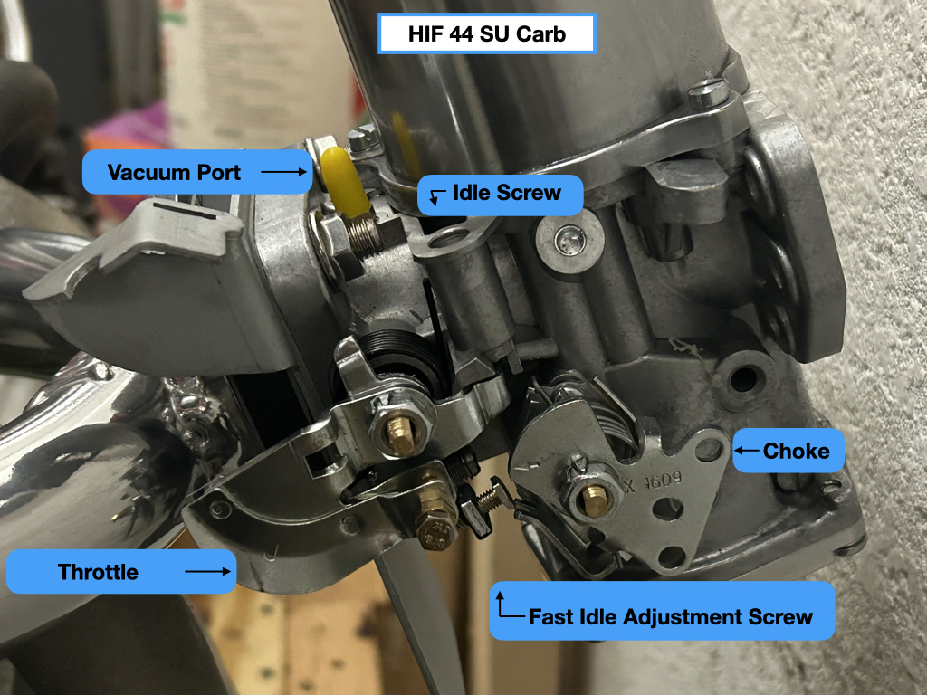
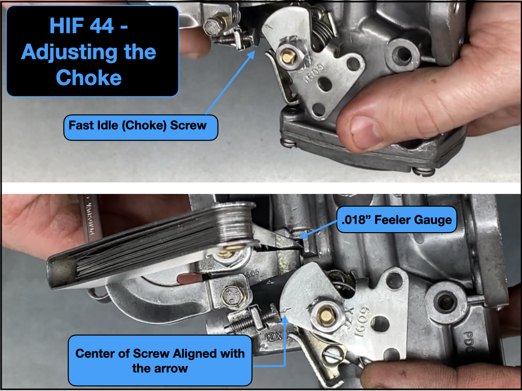
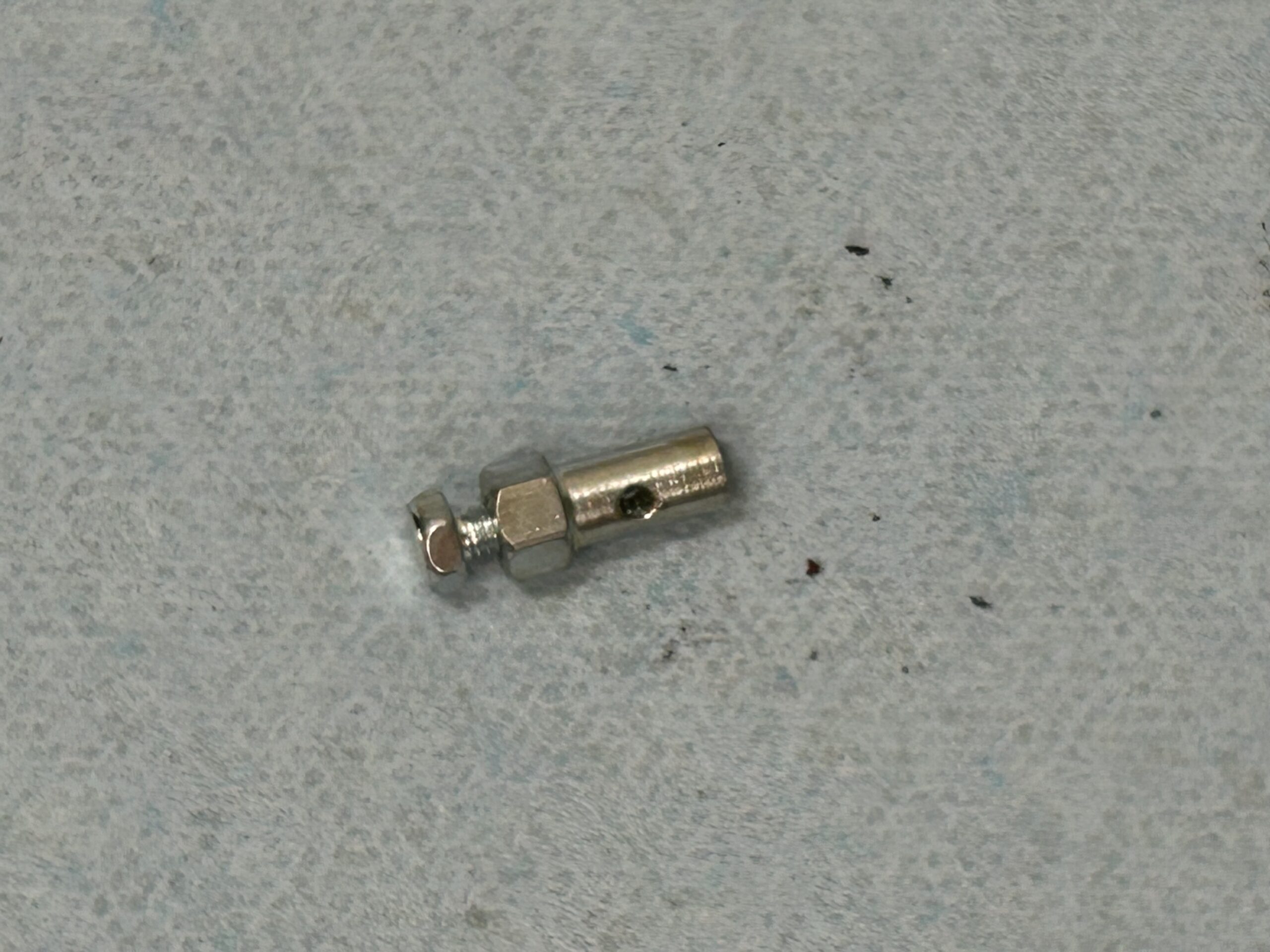
We then hooked up the choke cable to the carb and we installed a lawn mower throttle cable and slide controller on the control panel and also hooked it up to the carb. These are shown in the video with the link below.
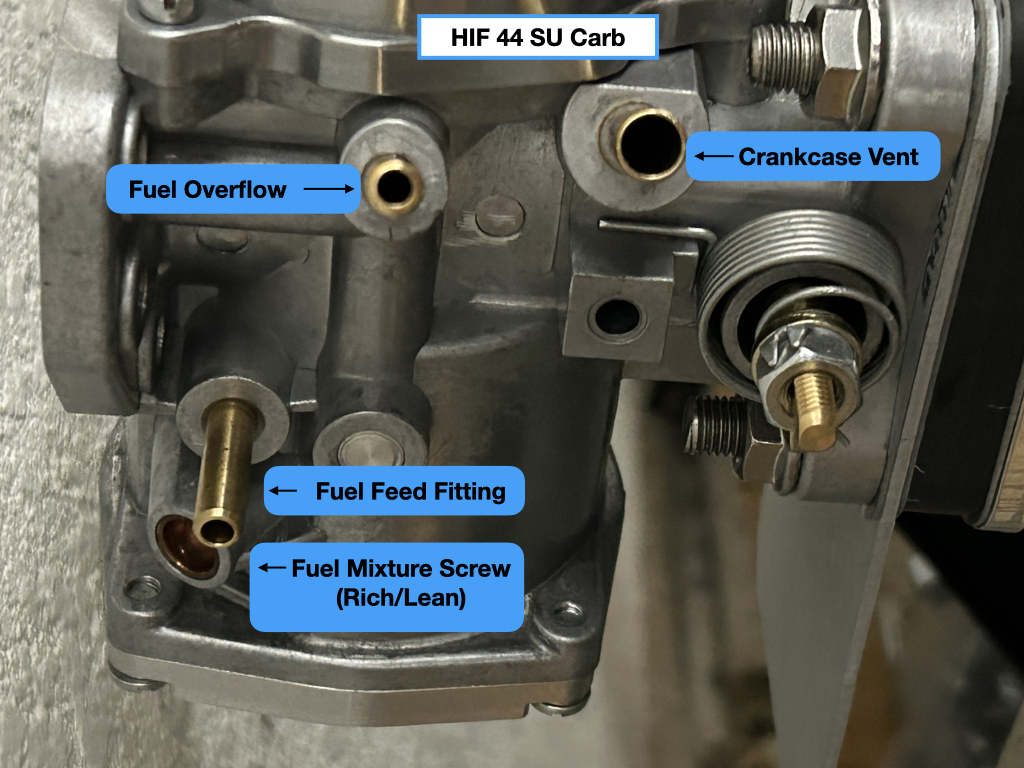
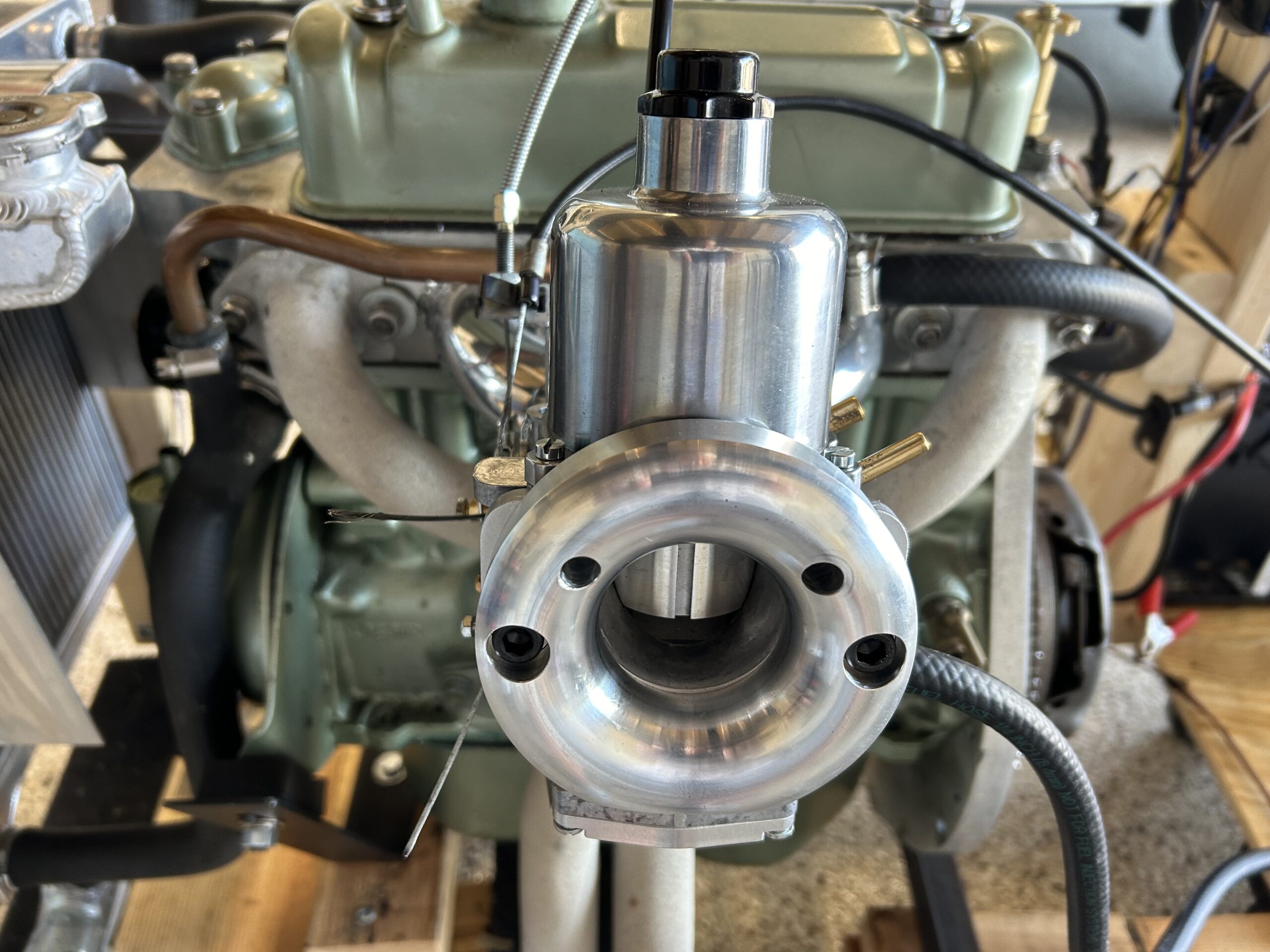
Water was then added to the radiator, Valvoline Racing Oil 20W-50 was added to the engine and some automatic transmission fluid was added to the HIF-44 damper. We then disconnected the coil and spun the engine with the starter until we had oil pressure. After checking ignition timing one more time, and testing for spark at the plugs. It was time to fire it up. It ran pretty well but seemed a bit rich at idle.
After a pause to work on other projects and to wait for parts, we came back to the engine to try to improve the engine’s tuning and to check on the clutch and ring gear.
The clutch had worked just fine but we decided to go ahead and replace the disc and pressure plate since the engine was out of the car. While we were at it, we also made plans to take the flywheel to a machine shop and have the face resurfaced and have the flywheel and clutch pressure plate, or cover, dynamically balanced. That is when things got interesting!
We took the flywheel to Southwest Hydraulics in Venice, Fl for resurfacing, but we got a call from them indicating that the flywheel was “coming apart.” As it turned out the flywheel had been lightened a bt too much and there was very little material between the flywheel lip and the ring gear. See below.
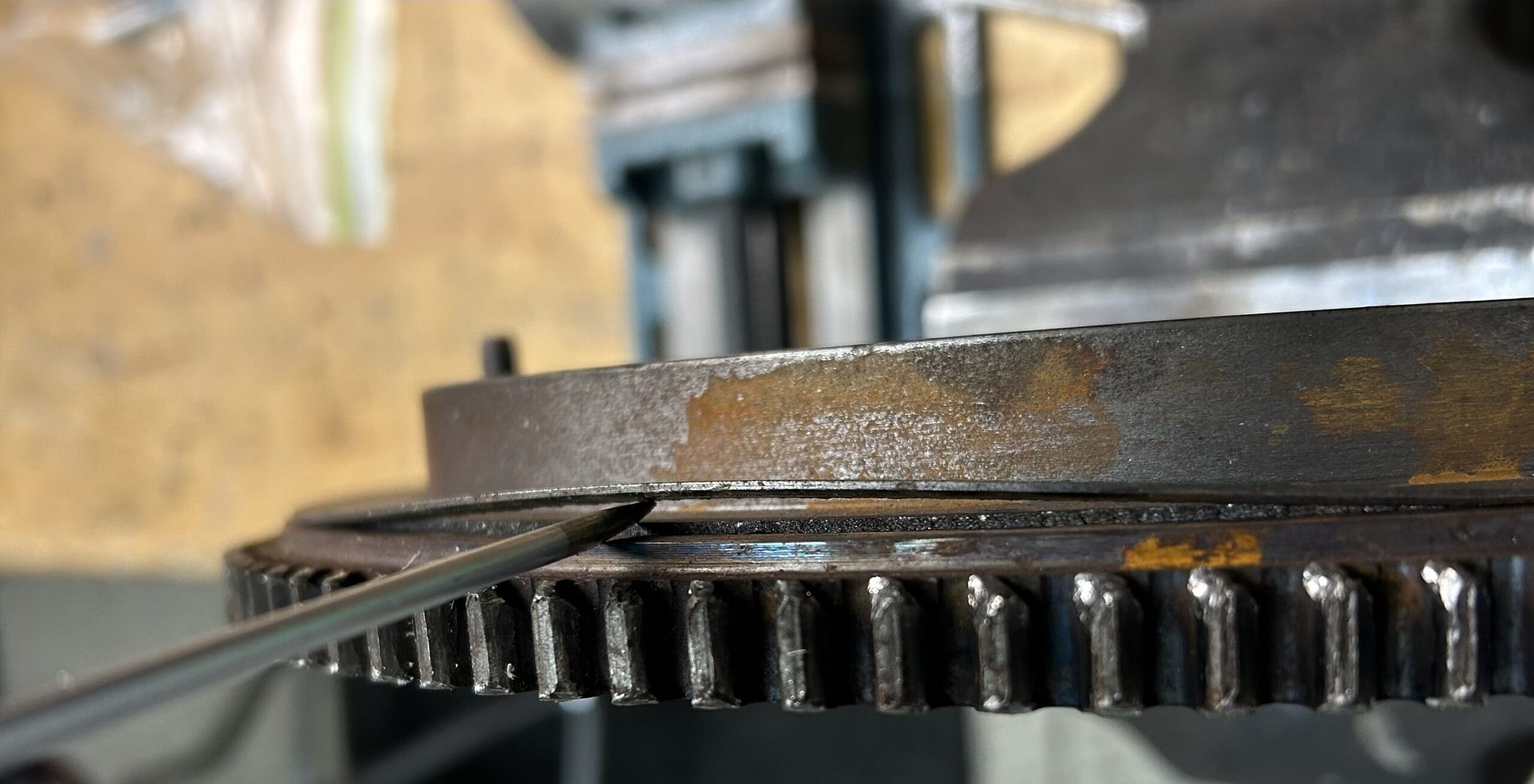
Flywheel delamination
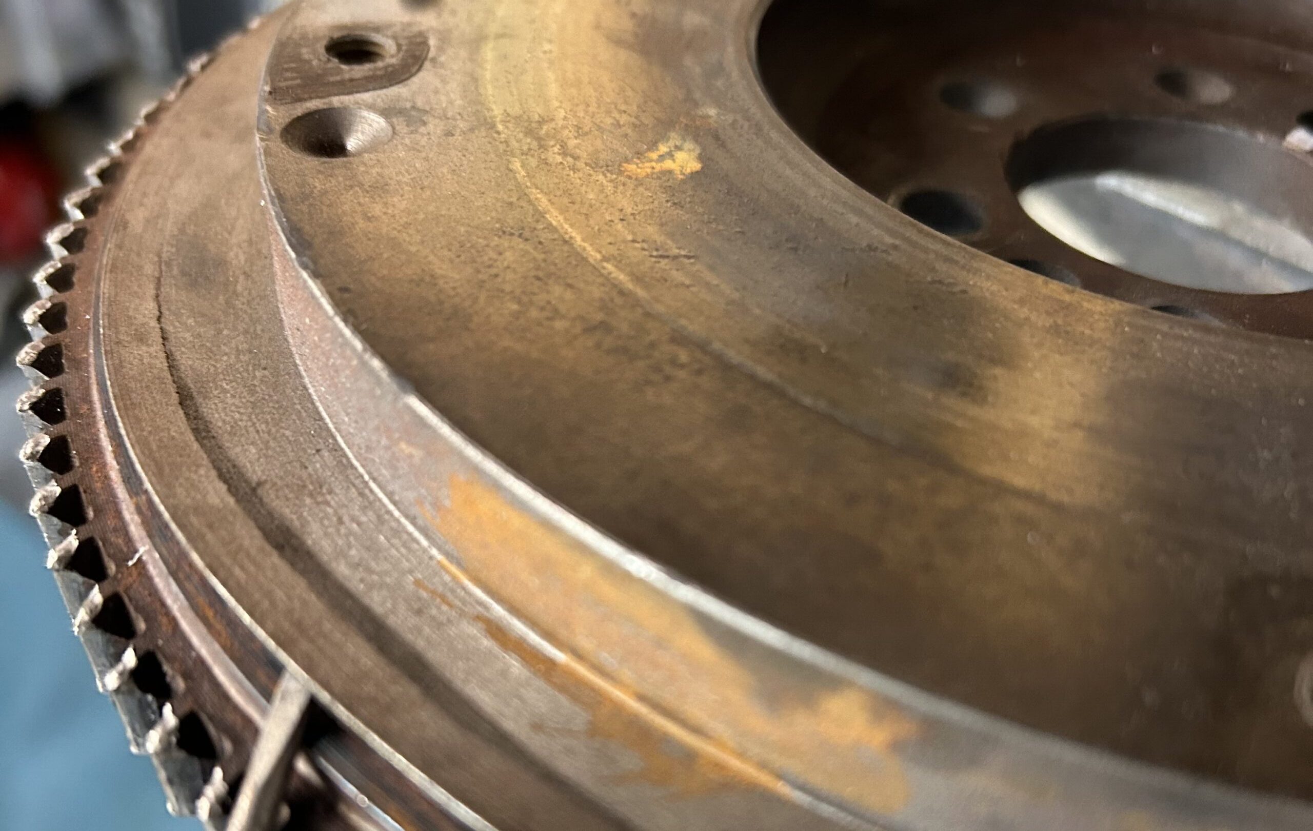
This is going into the trash!
Since they no longer make steel flywheels for the 1275 (aluminum lightened flywheels are available) we searched eBay and located one. It had not been lightened at all which we preferred, but it was not without its problems. One of the clutch cover bolts had been broken off in the flywheel. Fortunately, our friend Randy Forbes came to our aid. Using his milling machine, he first flattened the top of the bolt shaft and then with his drill press using a LH drill bit he was able to remove the broken bolt with no adverse effect. Thank you Randy!
We then took the flywheel back to Southwest Hydraulics for the resurfacing and we also had them replace the ring gear with a new one sourced from A.H. Spares
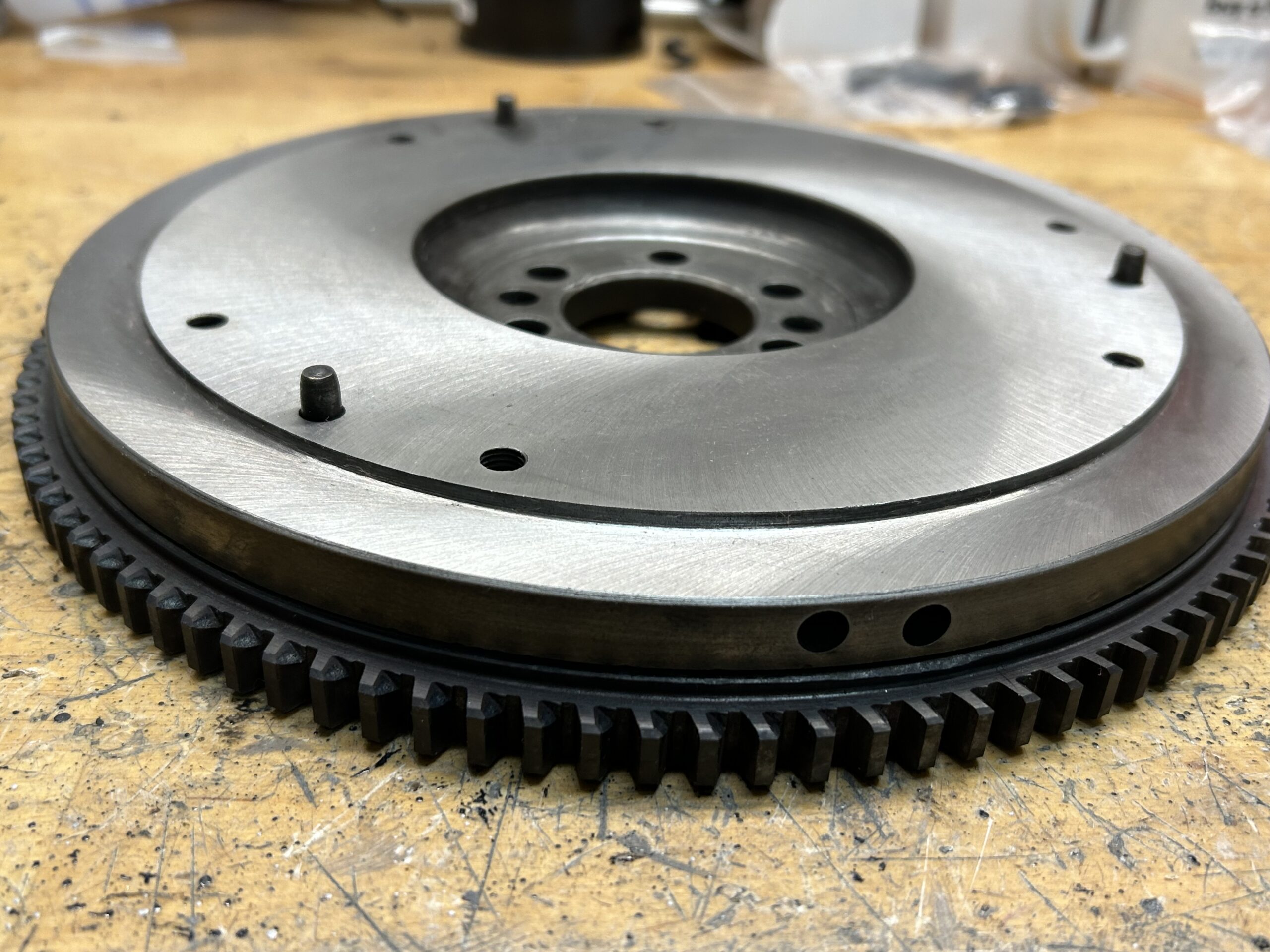
Flywheel resurfaced
Then it was off to “VAMI” – Venice Auto Marine machine shop where we had the flywheel balanced. Unfortunately, we could not balance the clutch pressure plate with the flywheel because the center hole in the pressure plate was too small to fit on their machine. This should not be a problem as the pressure plate comes balanced by Borg and Beck. The new disc was sourced from Rivergate.
We then reinstalled the flywheel, clutch disc and clutch pressure plate. The flywheel bolts were new and torqued to 4o ft. lbs. A locking tab washer was installed and all the tangs were bent over. The clutch bolts were torqued to 19 ft. lbs.
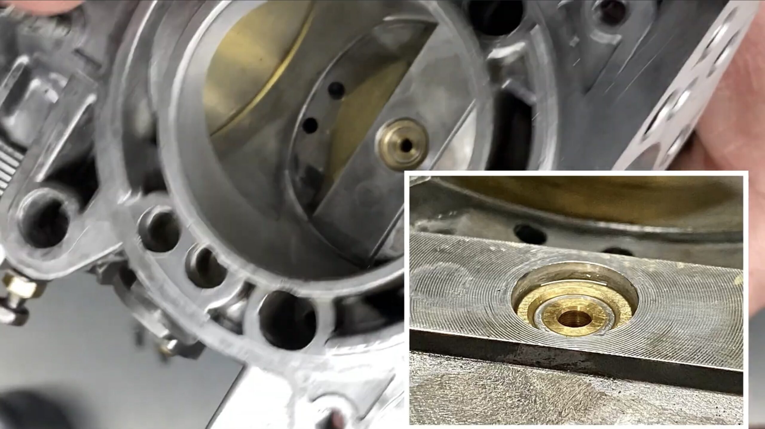
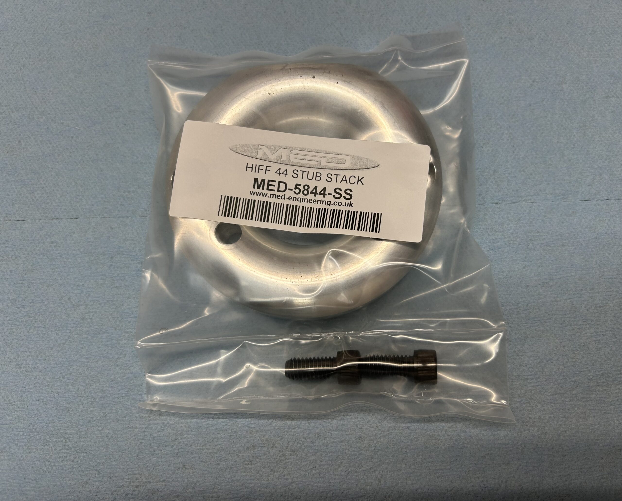
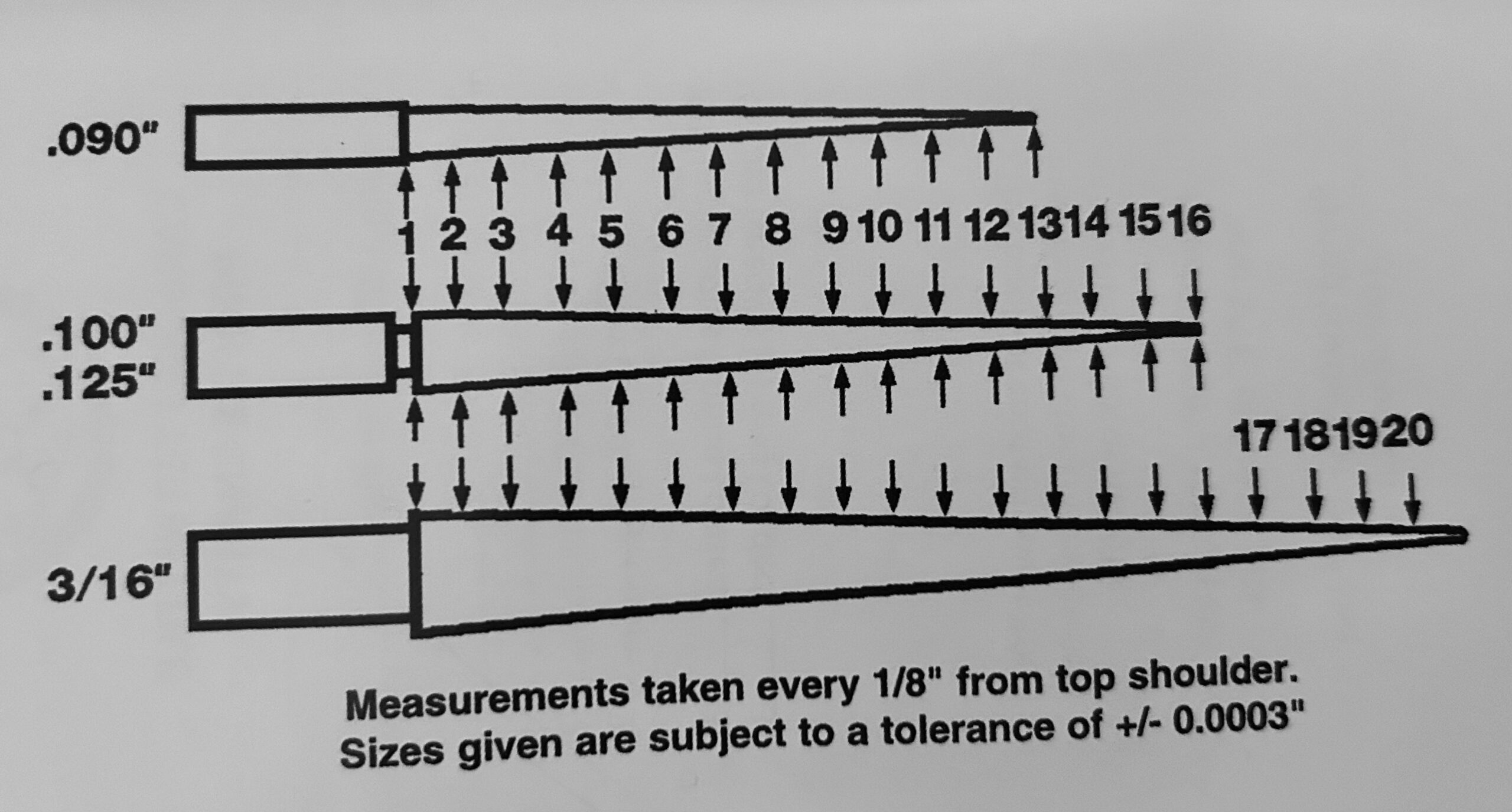
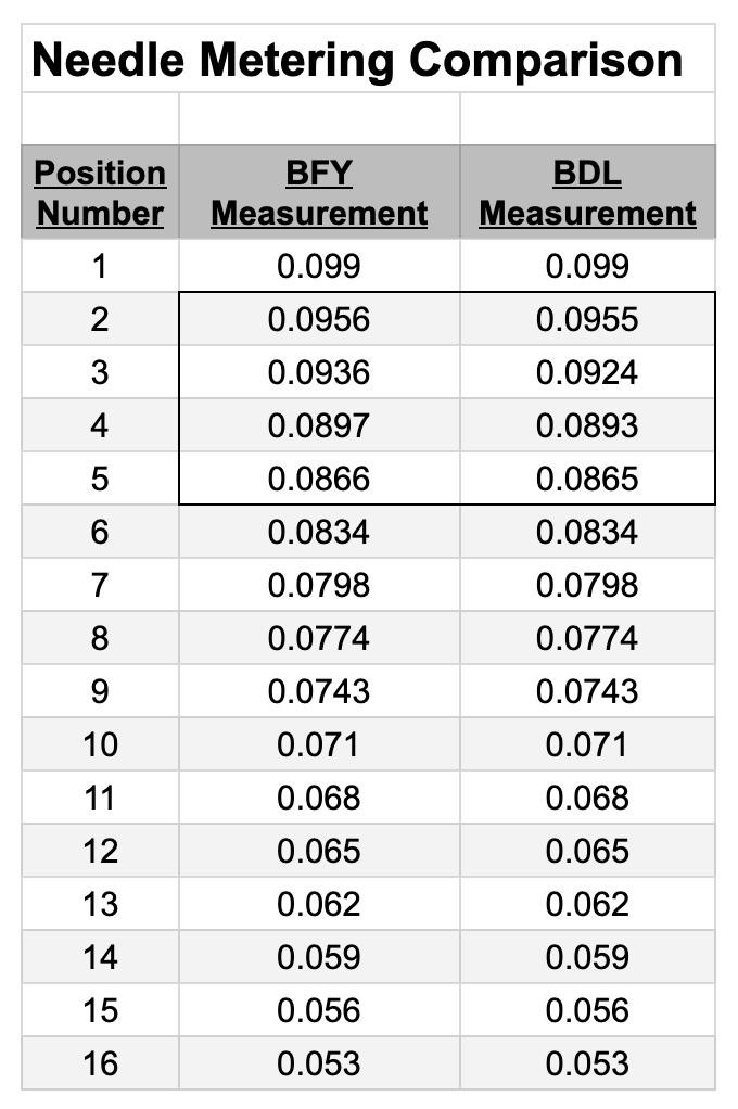
In the meantime, we replaced the metering needle that came with the carb with a “BDL” needle to get some additional fuel at start up without having to rely so much on the choke. Randy Forbes again came to our aid with the installation of our oxygen sensor.
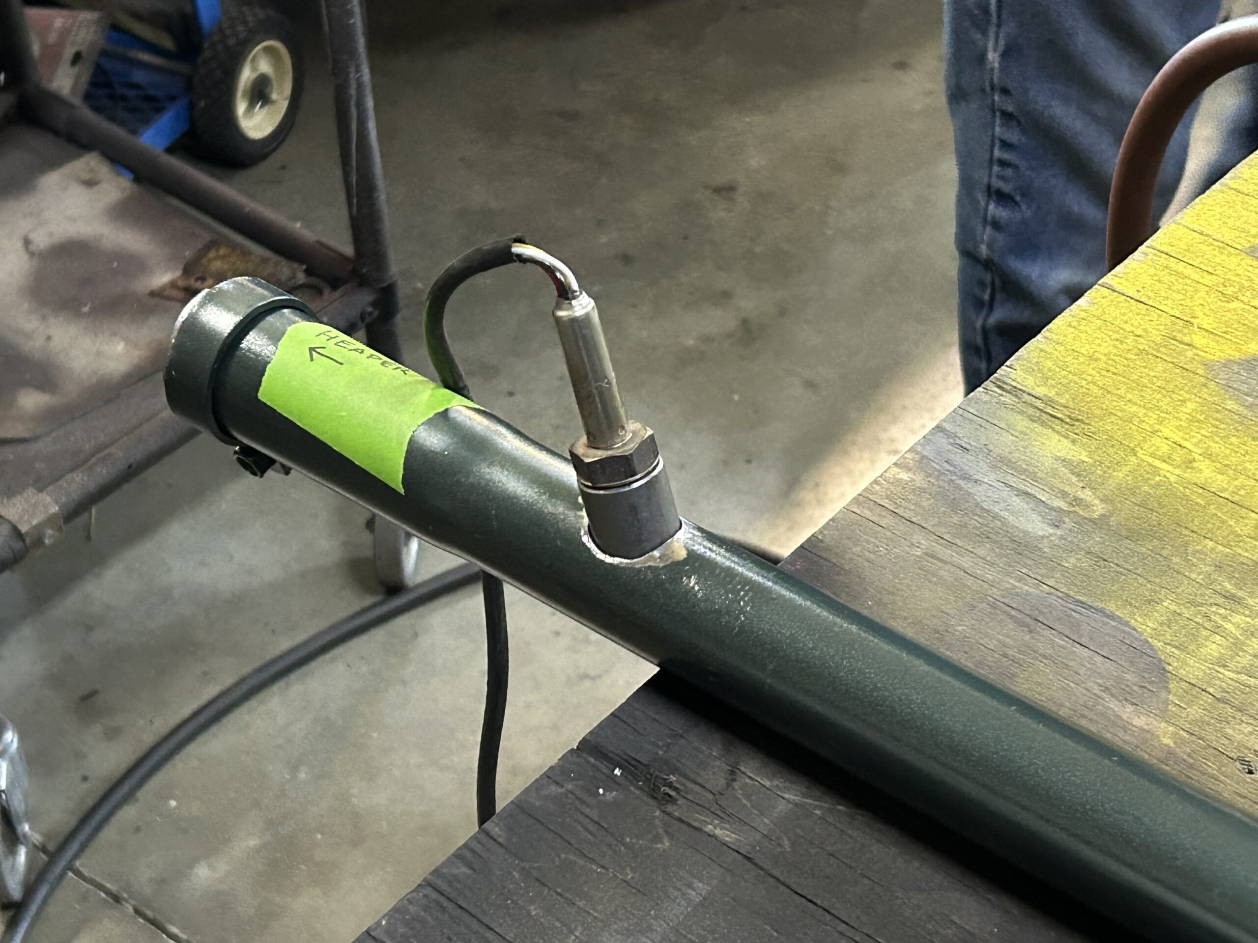
Oxygen Sensor Bung Installed
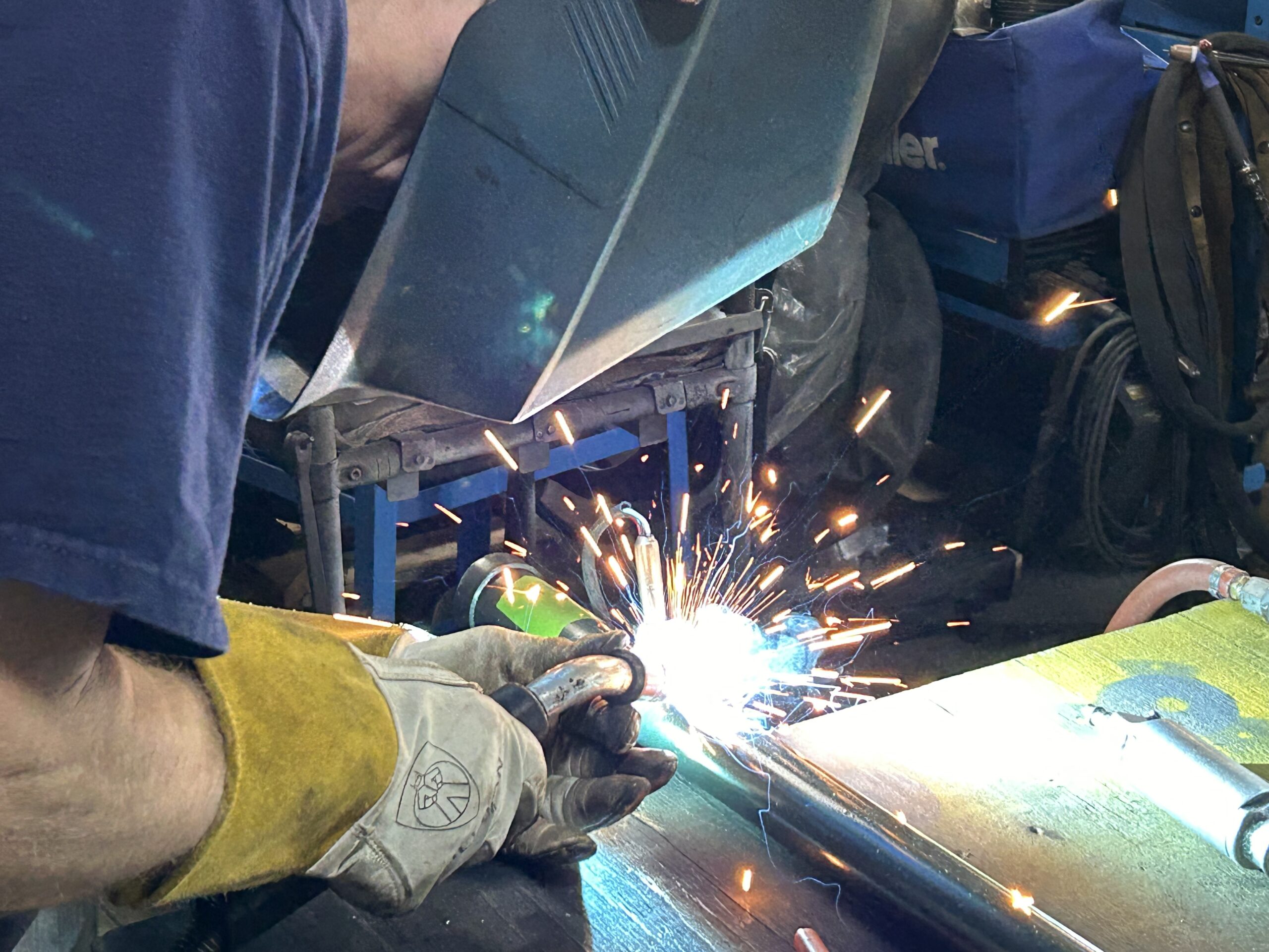
Randy doing his thing!
He installed a bung into our new exhaust pipe for the oxygen sensor so that we could use our newly purchased Innovate Motorsports AFR gauge. This is very helpful in adjusting the fuel mixture at the carb.
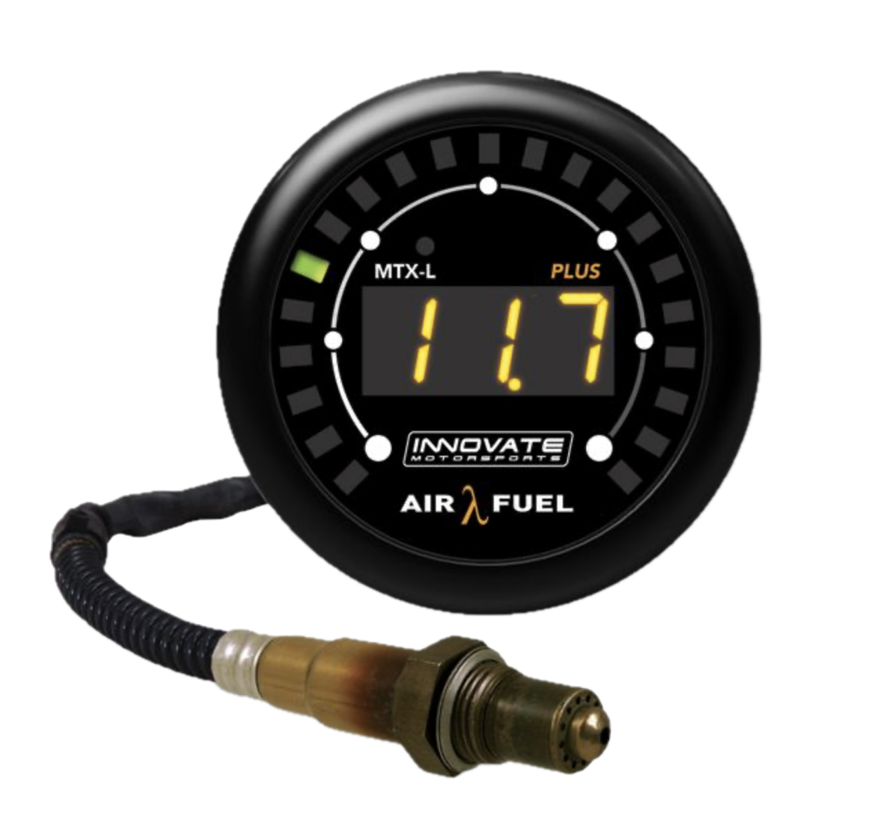
Innovate Motorsports AFR Gauge
Before starting the engine a second time we also decided to replace the original-type Lucas starter with the gear reduction starter we had.
We then started the engine a second time and we were pleased with the changes that had been made. The engine seems to be running well with a static advance of 12 degrees and a full advance of 31 degrees at 3,800 rpm. All of our changes and the first and second running of the engine are included in the Bugeye Restoration Video Episode Sixty.
https://vimeo.com/953122217/a96f4deab1?share=copy
Episode Sixty includes the following content:
0:35 – Gearbox removal
2:30 – Throttle control
3:35 – Choke cable
4:40 – Engine fluids
6:35 – Priming the oil pump
7:35 – Checking for oil pressure
8:10 – Ignition timing
8:32 – TDC Compression stroke
9:00 – Checking for spark
10:35 – Engine starts!
11:30 – Ignition timing again
12:20 – Marking the distributor setting
12:30 – Gear reduction starter reinstalled
13:10 – Innovate Motorsports AFR gauge
14:08 – Engine running again
14:45 – Engine storage until it goes in the car
The exhaust was then removed along with the intake manifold, the HIF carb, and the exhaust header. This was done because we are sending the exhaust header to Jet-Hot for a ceramic coating. We have now covered the engine and pushed her to the side. The good news which is really too good to believe, and surely will not last, is that we have no oil leaks!
Wow, we started this engine work back in September of 2023. Considerable time has passed but we were continually diverted to work on other parts of the restoration. Other than coating the exhaust header we believe the engine is now complete. Hopefully, by Christmas she will be reunited with the car and it will be as easy as installing the engine and gearbox and taking the car for an initial run!