Steering Installation

The steering installation story in the Bugeye has been characterized by fits and starts. This often happens in restorations because systems frequently interfere with the installation of other systems. The new steering rack was first discussed in Bugeye Restoration Video Episode Thirty-five: https://vimeo.com/810655660/46123c8339?share=copy The steering rack is a new one purchased from AH Spares. Information related to the steering rack begins at the 5:00 minute point of the video.

Bugeye Restoration Video Episode Eighty-seven shows the installation of the steering components of the car.

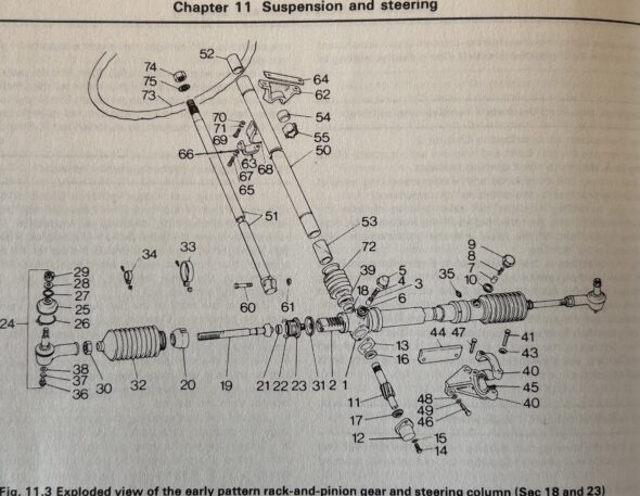
Bugeye Steering Components

We almost missed the shim that fits between the chassis crossmember and the passenger side of the steering rack bracket, part number 44 in the diagram above. This shim aligns the steering column through the dash at the correct angle. We sourced a new one from AH Spares.

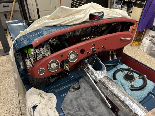
The trickiest part of installing the steering system was the coordination required with the installation of the dash. We installed the column through the firewall and let it hang loose. We then positioned it through the hole in the dash and gradually moved both the column and dash upward and into position on the car. Only then did we begin to connect the various components of the steering system. The horn cone was installed with its three mounting screws, but with plenty of room to move around as the column shifted position. All parts were loosely fitted to ensure that we didn’t have any binding of the parts as they were assembled.

Dash with zip ties to the body and column in position

In our final installation we had already centered the steering rack and had also threaded the new tie rod ends to the proper location to hopefully result in a rough alignment of the wheels permitting us to roll the car around in the garage. We will find out later if we were successful! Of course, we will align the steering professionally when all is done.

The following points are covered in Bugeye Restoration Video Episode Eighty-seven:

https://vimeo.com/1010637487/a43c135b98?share=copy

0:00 – Steering column bracket, grommet, and bushings

1:56 – Steering column firewall corrugated grommet

2:18 – Stering rack shims

2:49 – Steering column to steering rack locking bolt

3:00 – Steering rack to chassis brackets installed

3:22 – Steering rack to chassis shim

4:12 – Steering rack bracket bolt torque values

4:22 – Coordinating the dash and steering column installation

4:40 – Final steering components installation sequence

6:19 – Horn cone positioned and secured

7:22 – Testing the steering column connection to the rack

8:20 – Connecting the tie rod ends

9:00 – Steering wheel installed

9:30 – Horn test


nn

Chapter 16 – Cleaning and Trial Fitting

November 16, 2003

Front Suspension 

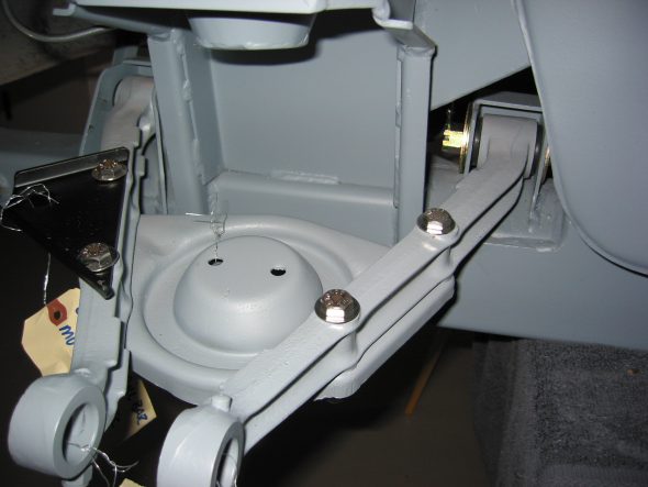
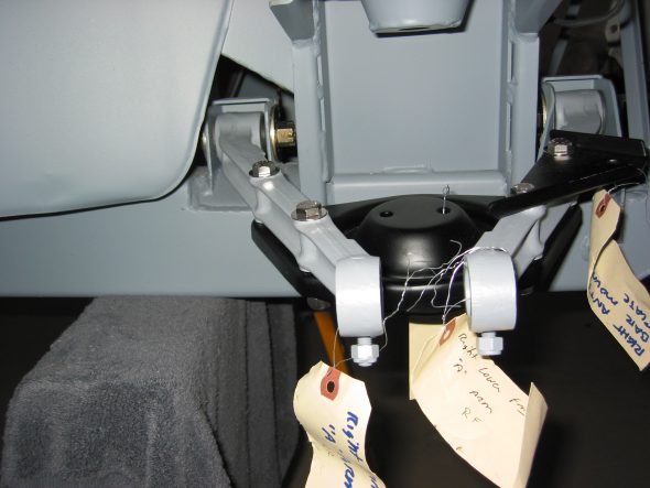
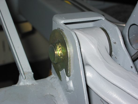
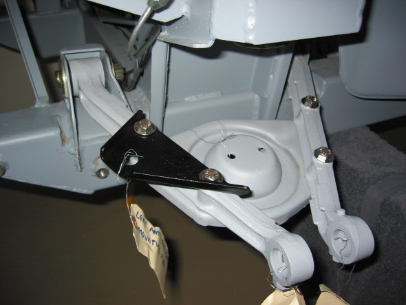
Control Arms and Bushings – Installed left and right lower control arms with rubber bushings and fulcrum pins.

Left control arm 3

Right Control Arm 2

left control arm 1

Left control arm 2

December 14, 2003

Steering

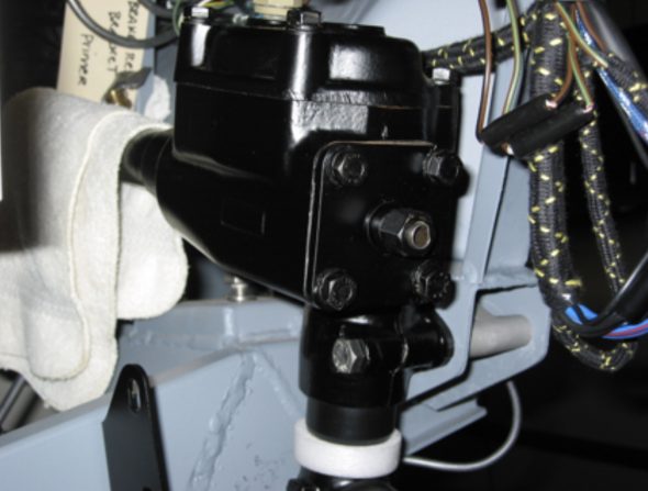
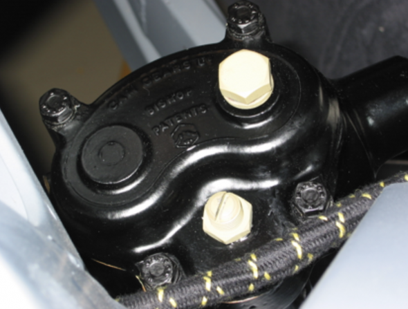
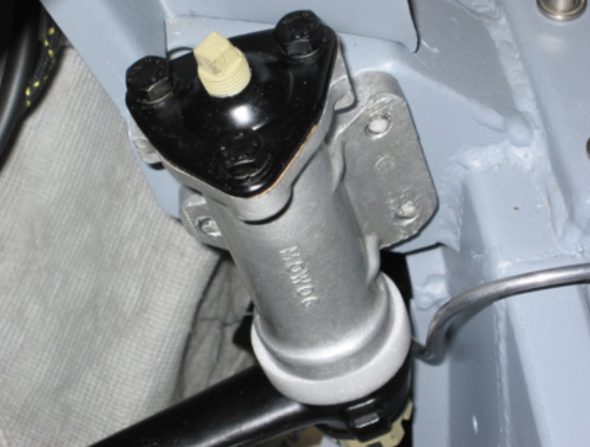
Steering Box and Idler – Picked up the painted steering box and steering idler from Jeremy Turner. Jack Harper disassembled the units and reassembled following painting. Jeremy did a great job on the steering wheel shaft as it was pitted near the box. Installed the Box and idler. Note for future – install box and idler before front brake hose bracket, as the bolts/nuts get in the way.

Steering Box Installed

Steering Box In Place – Fill Plug & Adjuster

Steering Idler in Place

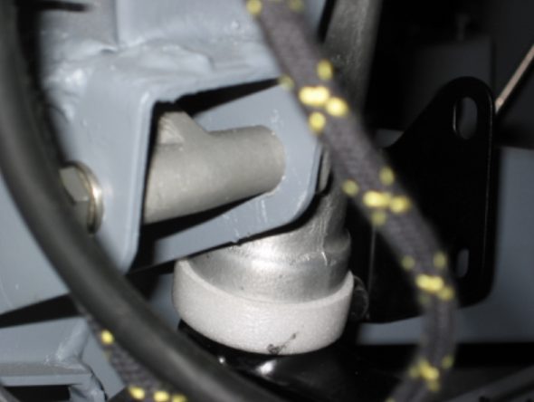
Steering Idler Installed with Aluminum Spacer

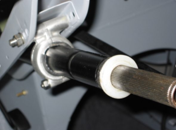
Steering Column with Brace

January 10, 2004

Blistein Tube Shock Conversion 

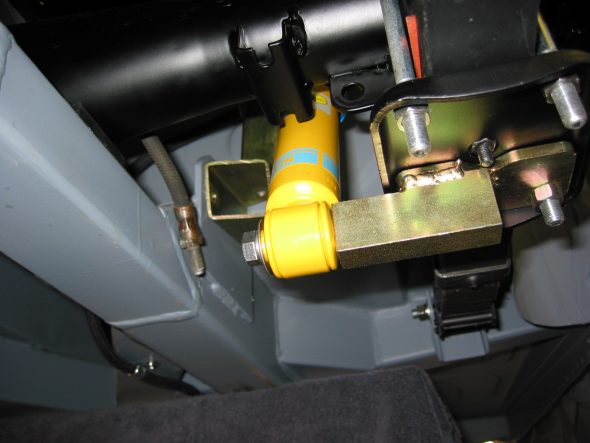
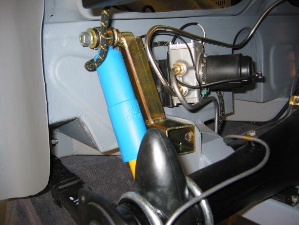
Rear Tube Shock Conversion

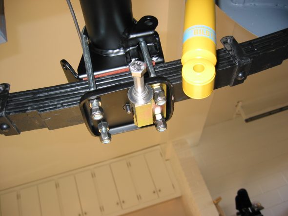
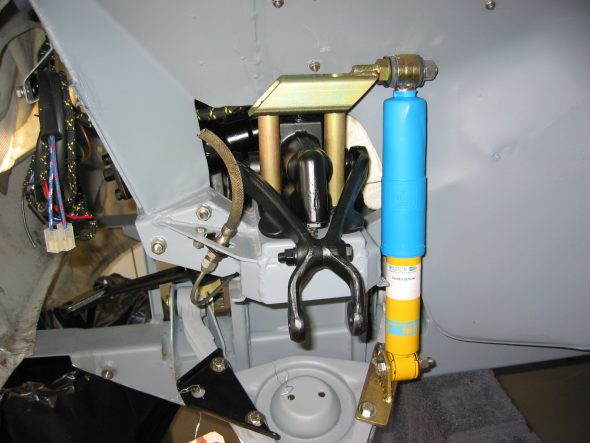
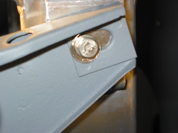
Installed Udo Putzke’s Blistein tube shock conversion kit in the rear suspension. Two fabricated brackets on each side of the rear of the car. Original lever shock is abandoned completely in the process. Couldn’t complete the final connections because when the leaf springs were jacked up to align the shock for fastening, the entire car raised since the engine is not in the car, thereby giving it sufficient weight. Will have to complete later in the assembly process. Rear tube shock is F4-BE3-2577-HO. The brackets will need to be painted for final assembly. They should be installed prior to the fuel pump.

Tube shocks rear 4

Tube shocks rear 6

Tube shocks rear 2

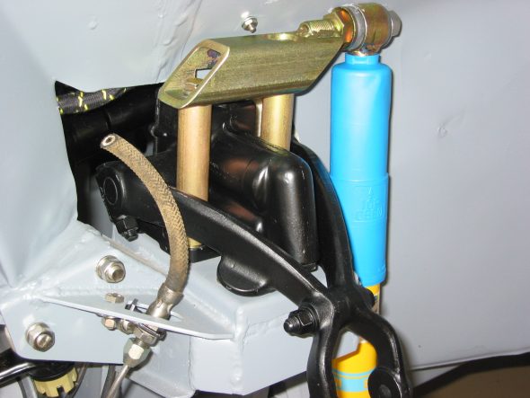
Front Tube Shock Conversion

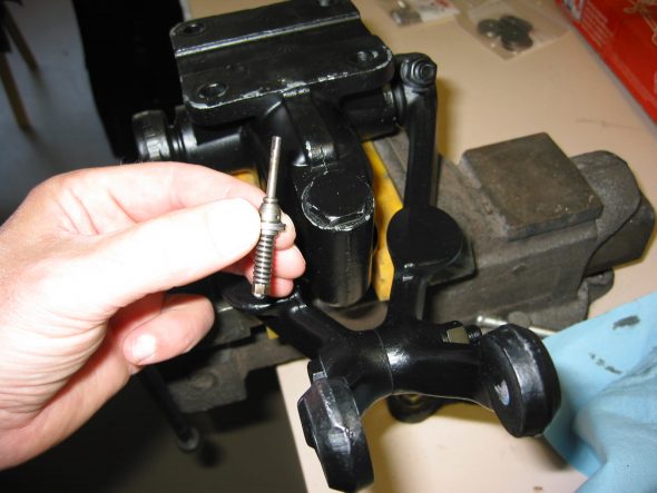
Installed Udo Putzke’s Blistein tube shock conversion kit in the front suspension. Two fabricated brackets on each side of the front of the car. Original lever shock is utilized in the process. To make sure the lever shocks would not leak fluid in the future, they were rebuilt by World Wide Imports in Madison, Wisc. The valves are removed from each damper. The standard bolts are used to secure the damper nearest the motor. Supplied long bolts and support rods are used for the outside two mounts. Front tube shock is F4-BE3-2576-HO. The brackets will need to be painted for final assembly. 

lever shock valving

front tube shock conversion 2

front tube shock conversion 1

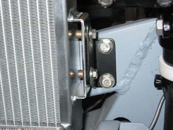
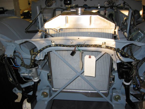
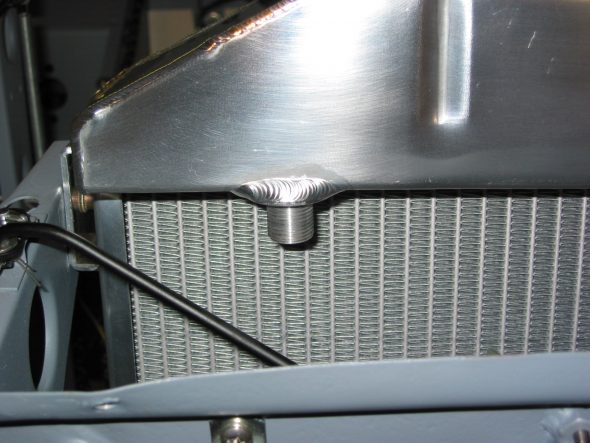
Aluminum Radiator  – Installed a new aluminum radiator from Cape International. Christmas gift from Jude. It is a piece of art, almost hate to put it in the car! Fit was perfect, although mounting fittings were metric. Easy installation is to loosen lower brackets on frame, secure top two bolts first, then secure lower bolts to radiator. Finally, tighten lower brackets to frame. Pull unit to front of car when tightening to get maximum clearance for fan.

Aluminum Radiator 3

Aluminum Radiator 2

Aluminum Radiator 1

Aluminum Radiator 4

Steering Column

Steering Column

Steering Column Cover Assembly

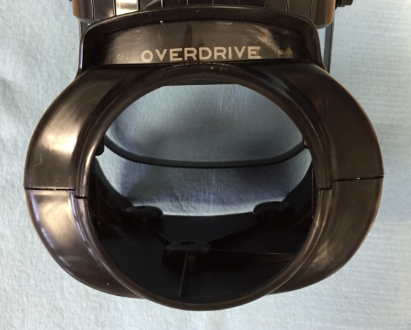
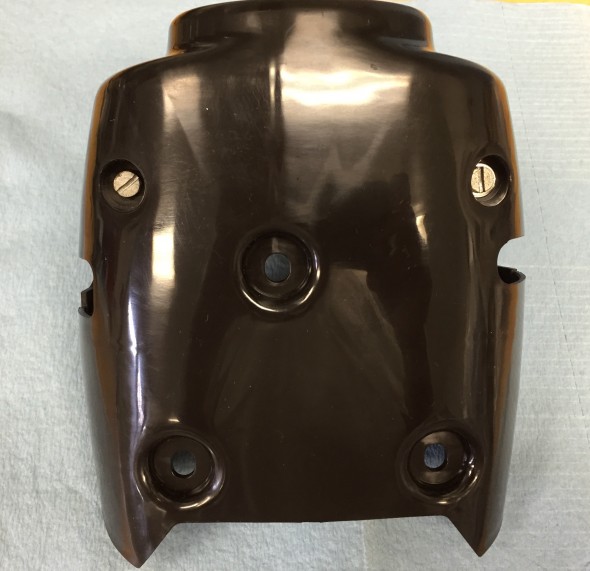
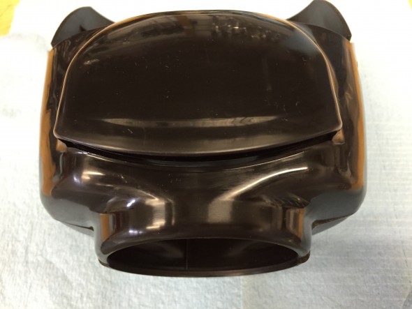
Unfortunately, the cover on my steering column was broken, but these plastic pieces are available from the usual vendors. I ordered new halves and assembled them with the original overdrive indicator and clear plastic lens. The assembly consists of the Upper Steering Cover Assembly at Center of Steering Wheel (with indicator plate inscribed ‘Overdrive’) and the Lower Steering Cover at Center of Steering Wheel.Both the indicator plate and the lens cleaned up with a little soap and water and plastic polish.

Steering Cover Assembly

Steering Cover Assembly

Steering Cover Assembly Bottom Half

Steering Cover Assembly Bottom Half

Steering Cover Assembly Top Half

Steering Cover Assembly Top Half