While my car usually runs at a reasonable operating temperature, I do get a little worried about the potential for getting stuck in traffic, and now that we are in southwest Florida with routine summer temperatures often in excess of ninety degrees overheating could occur.
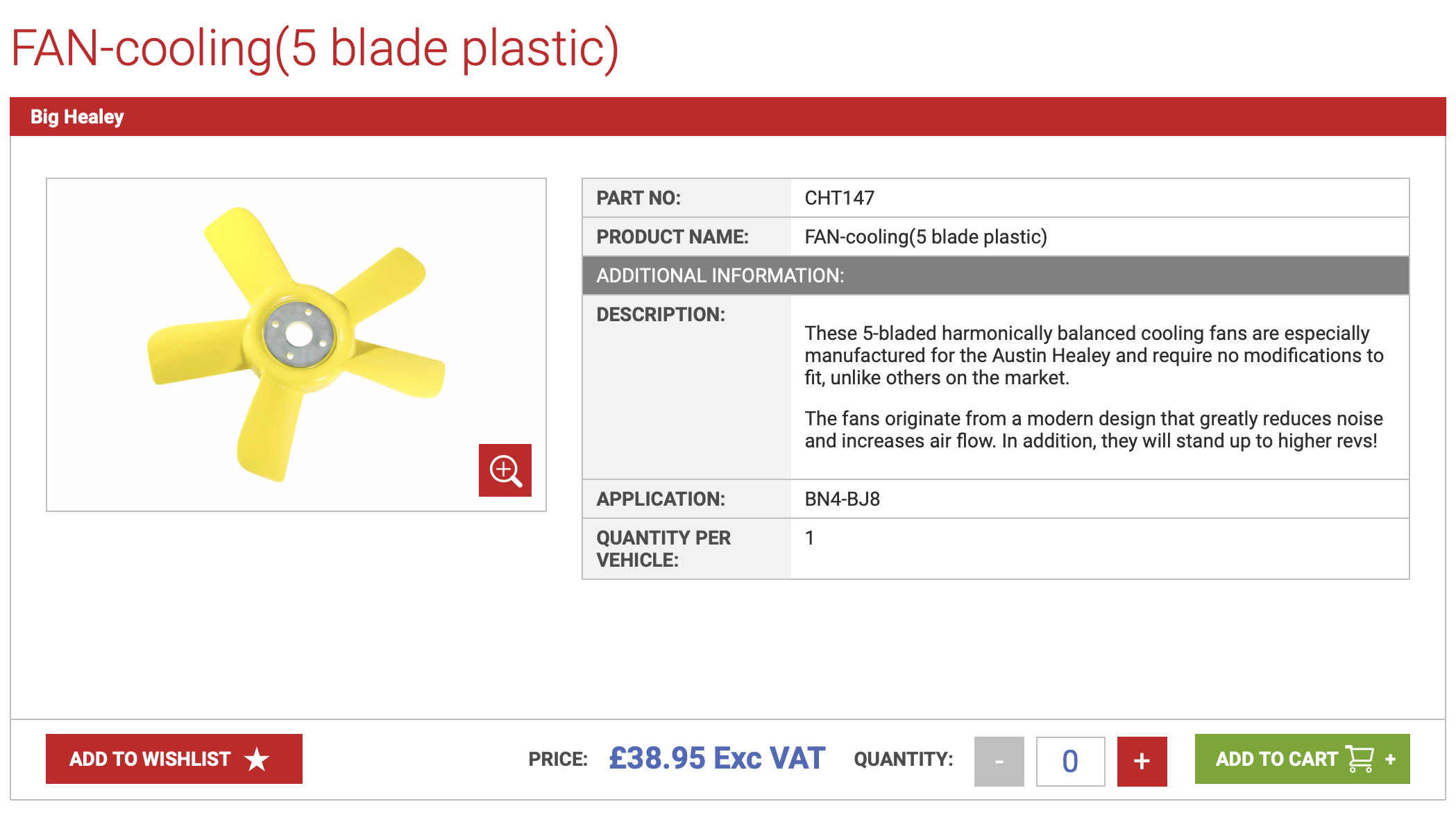
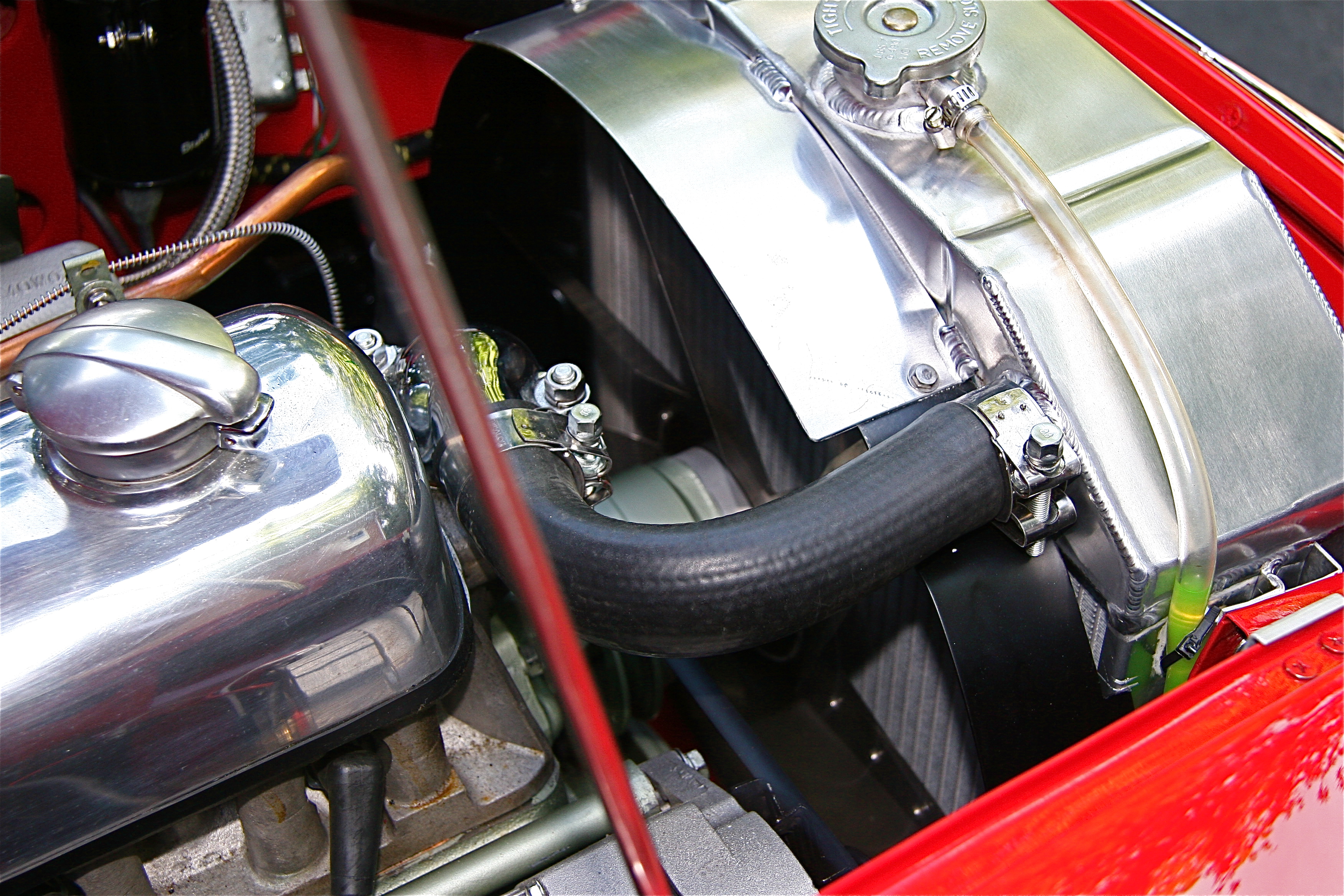
I have already applied all of the typical tricks for improved engine cooling: aluminum high capacity radiator, baffling to direct the air to the radiator core when the car is moving, shroud around the mechanical fan, improved fan, clean engine internals and etc.
While I do not need an electrical pusher fan in normal operating conditions, I think an electrical fan, operated by a toggle switch in the interior, may provide a good solution for those situations where I find myself sitting in traffic, or in a local parade. One could install a temperature sensitive switch to automatically turn the fan on/off at prescribed temperatures, but I have decided that I will just stick with a simple on/off toggle switch. I really hope that I will rarely need to use the electric pusher fan!
Some others on the various Healey Forums have suggested that an electrical fan may actually block the flow of air through the radiator that could result in higher running temperatures – I hope that will not be the case.
FAN SELECTION
The first step in this little project is the selection of the fan to be used. Factors to be considered include the width, height, and depth of the fan, the amperage draw (not much of a concern given that the Beast has an alternator installed rather than the original generator), and the fan’s output measured in CFMs or cubic feet per minute.
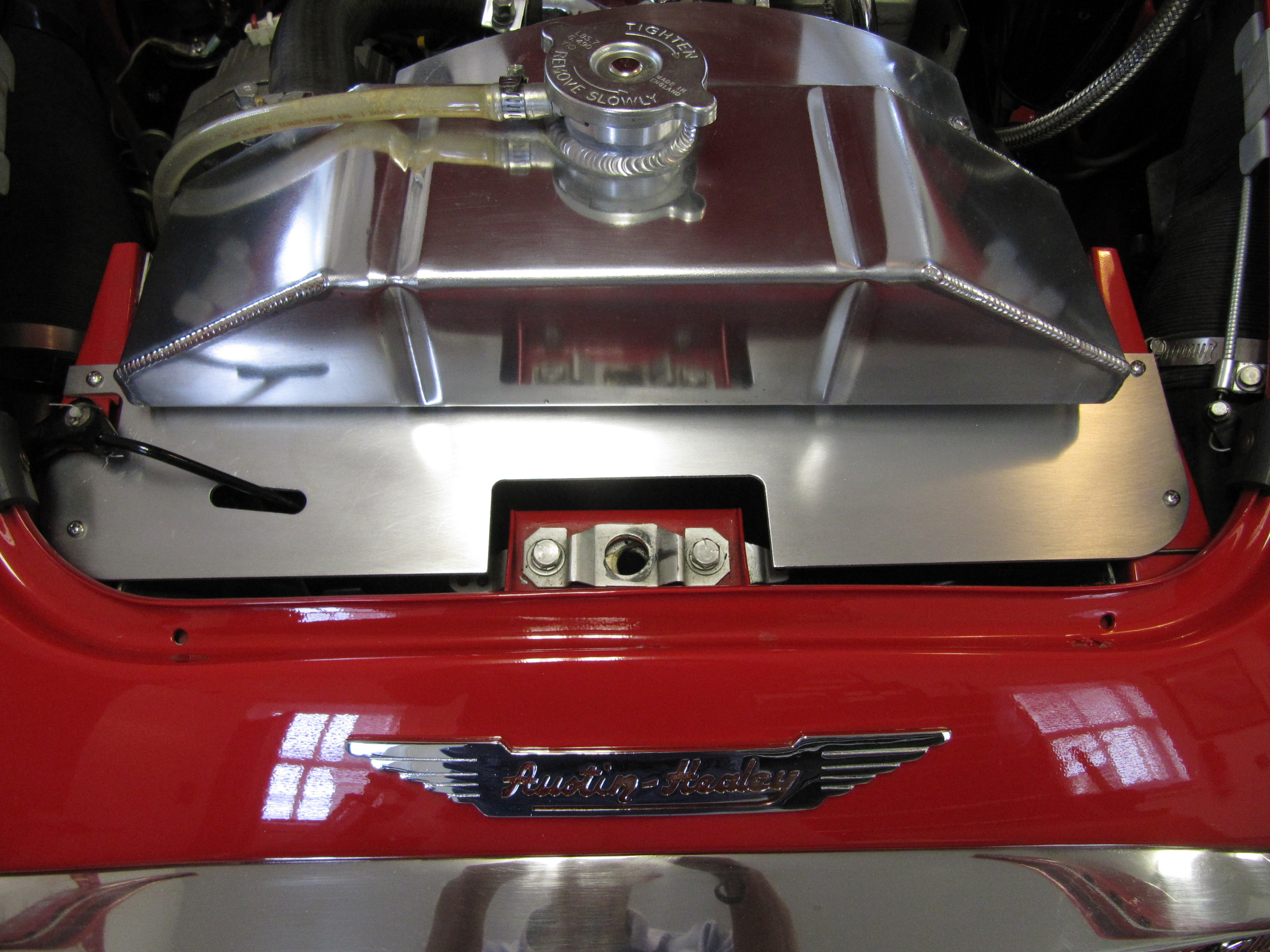
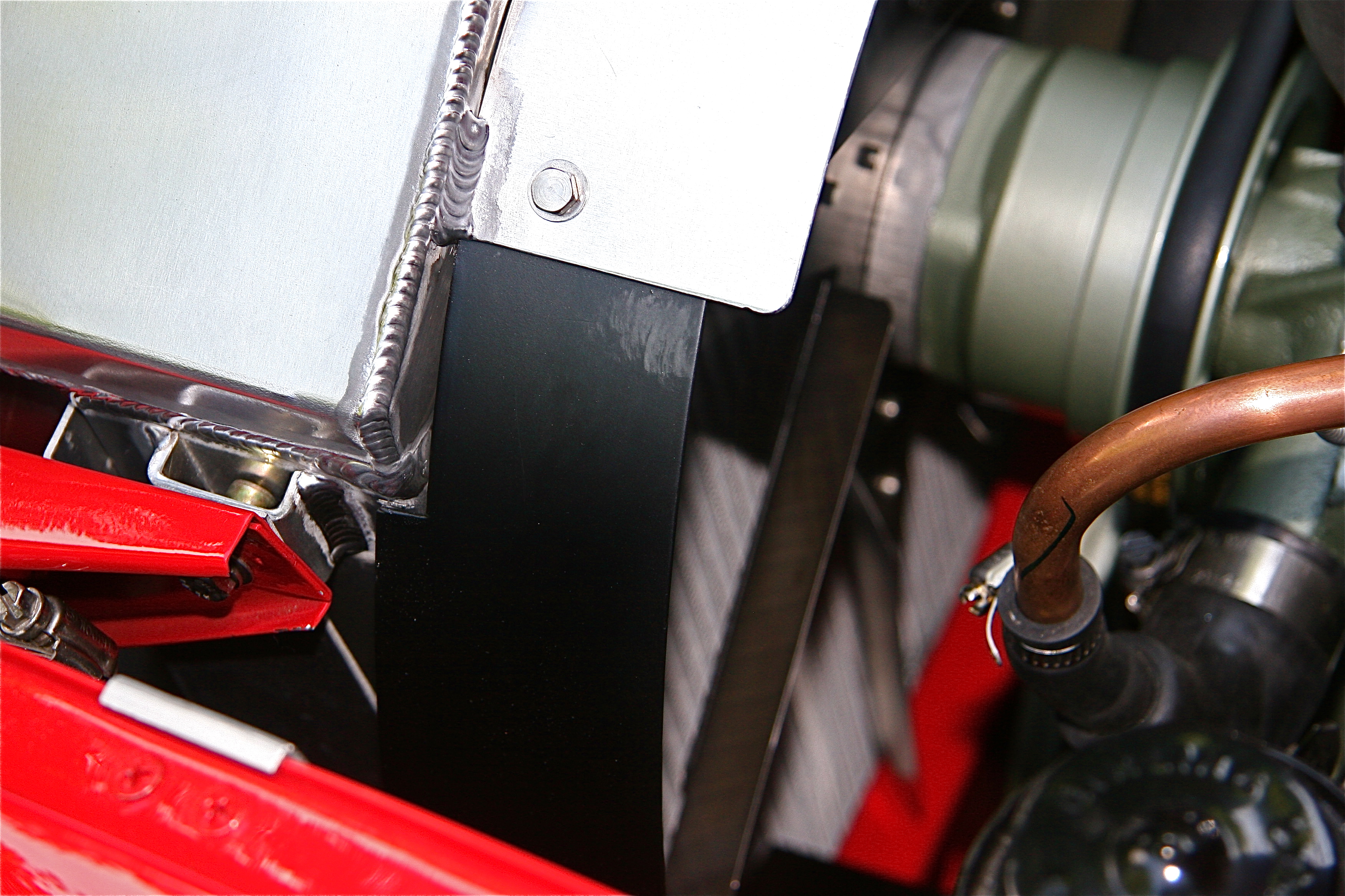
I am somewhat restricted regarding the size of the fan I will use. My aluminum radiator has fan mounting clips already welded to the sides of the radiator and I want to use them for fan mounting.
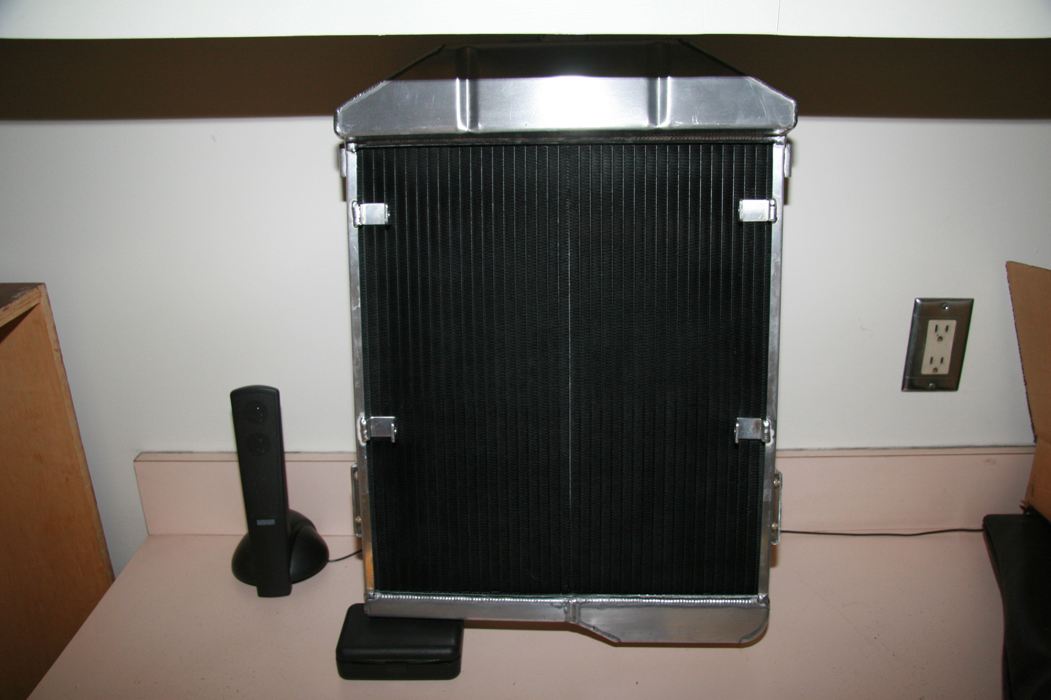
Aluminum Radiator with Fan Mounting Brackets
Consequently, a 12” circumference fan is the largest I can use. The “X” body brace in front of the radiator restricts the depth of the fan. A quick measure produced a maximum depth of 3.” Given these parameters I searched the internet for an appropriate solution and decided on a Maradyne product from Summit Racing.
The Maradyne M123K has the following specs:
Brand: Maradyne High Performance Fans
Manufacturer’s Part Number: M123K
Summit Racing Part Number: MAR-M123K UPC: 810349010123
Puller: Yes Pusher: Yes
Fan Diameter (in): 12.000 in.
Fan CFM Range: 1,100-1,199
Maximum Fan CFM: 1,155 cfm
Height (in): 13.230 in.
Width (in): 12.520 in.
Thickness (in): 2.610 in.
Number of Blades: 10 blades
Blade Material: Plastic Blade Color: Black
Shroud Color: Black Shroud Material: Plastic
Amp Draw: 7.20 amps
Mounting Brackets Included: Yes
Mounting Hardware Included: No
Notes: 130 Watt motor.

Maradyne Fan Image
PUSHER VERSUS PULLER
This particular fan can be a pusher or a puller. As shipped it is a puller so the first step is to reverse the fan. To do so one lift the safety catch over the shaft end and carefully pushes the clip off the motor shaft.
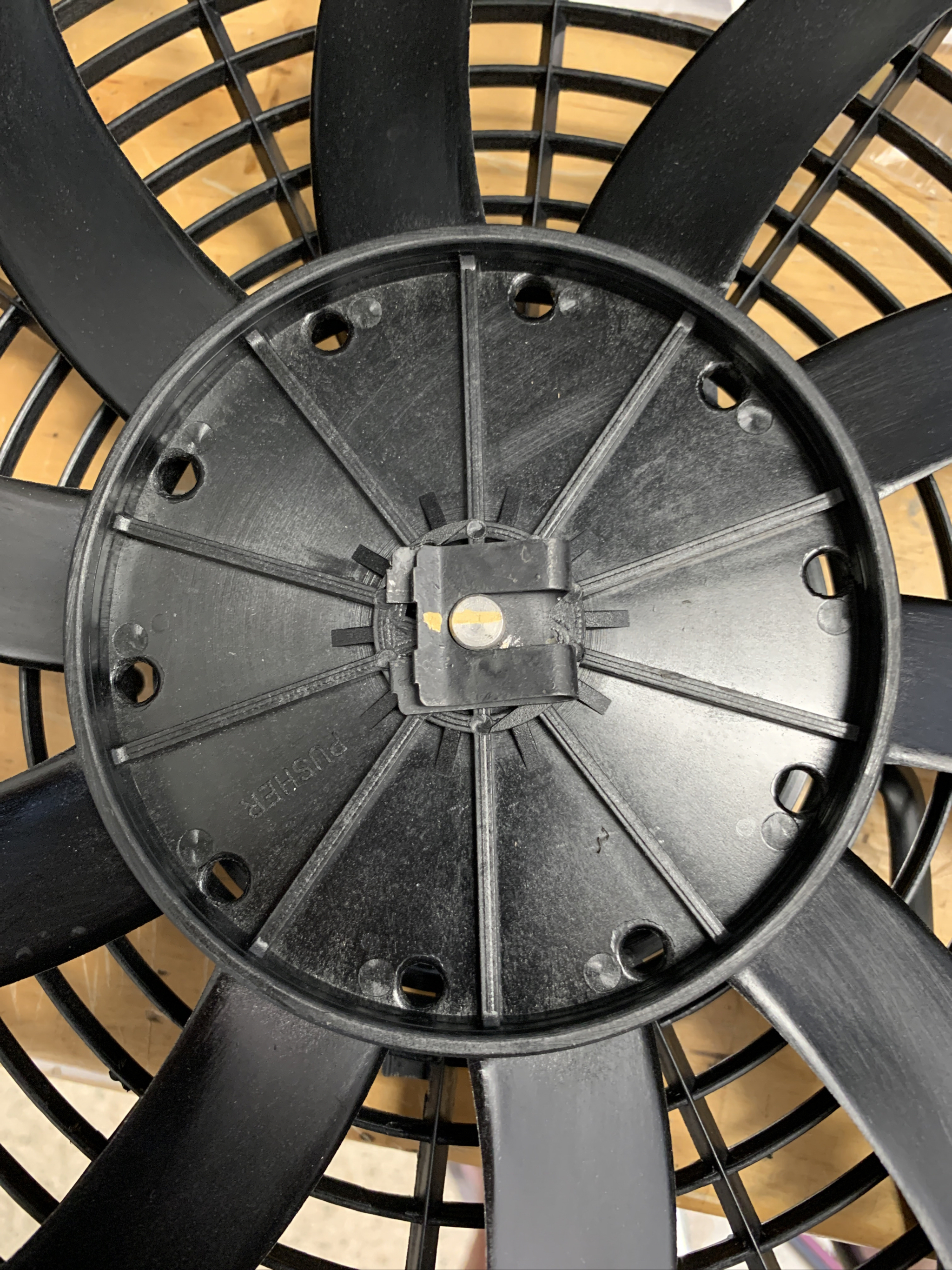
Maradyne Fan
The fan instructions then indicate with another person, carefully pull the blade off the motor shaft. Flip the blade, then place back on the motor shaft by lining up the groove on the blade hub with the drive pin on the motor shaft.
Then replace the clip by pushing the clip into the groove on the motor shaft. Ensure safety catch snaps over the motor shaft. Pusher configuration is now complete.
In the pusher configuration the blue wire to the motor is the negative connection and the black wire to the motor is the positive connection.
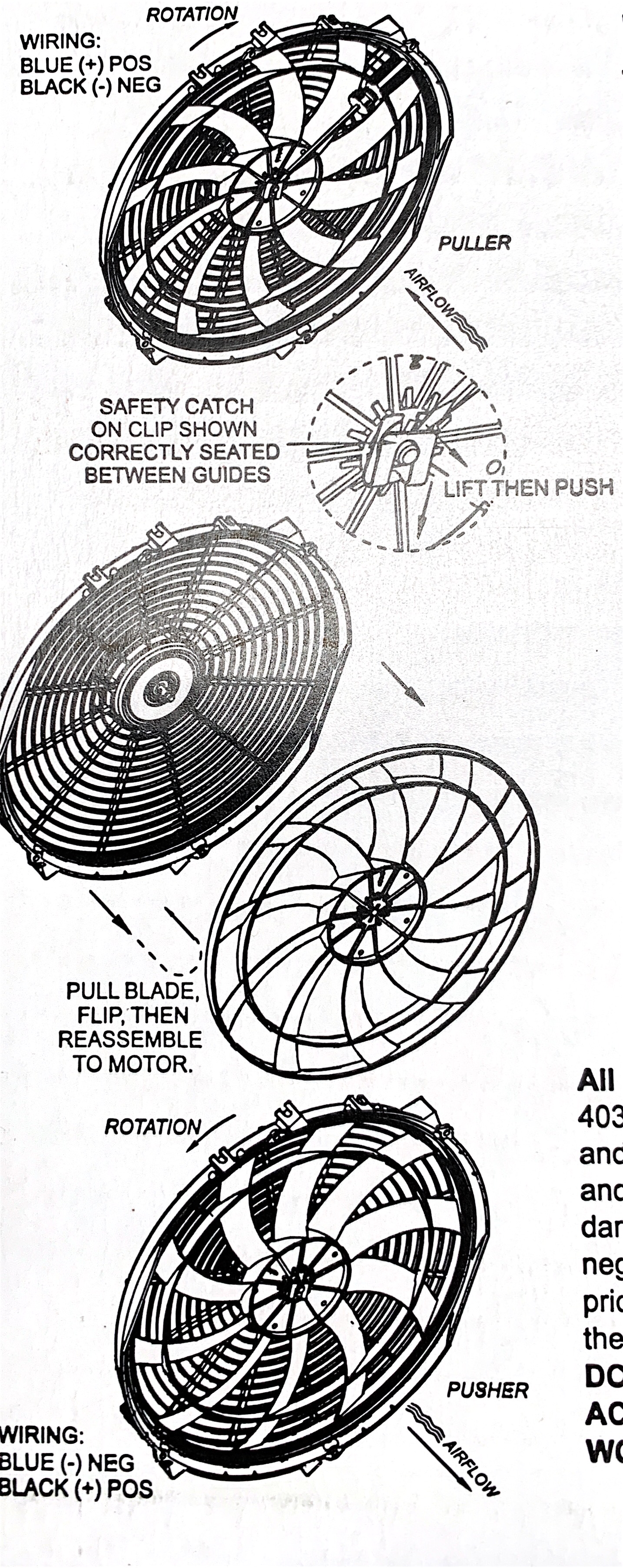
Maradyne Fan Rotation Diagram
I made the job of creating brackets linking the fan to each of the four mounting tabs on the radiator a bit harder than it needed to be because I did it with the radiator mounted in the car. I really didn’t want to drain coolant and pull the radiator out to make the brackets on the bench. Consequently, some trial and error was involved, but I got there!
Having the car on the garage lift made the task simpler than it would otherwise be. I cut the brackets out of some off-the-shelf steel sheet purchased at the hardware store, and after checking the fit I painted the brackets black for rust protection. I then installed the fan using four 1/4“-28 x 1/2” and four 1/4”-28 x 3/4” stainless bolts and nylock nuts.

Electric Fan Mounting Brackets
Maradyne supplies four rubber cushions or feet that hold the fan away from the radiator cooling fins:
Rubber Cushion Spacers
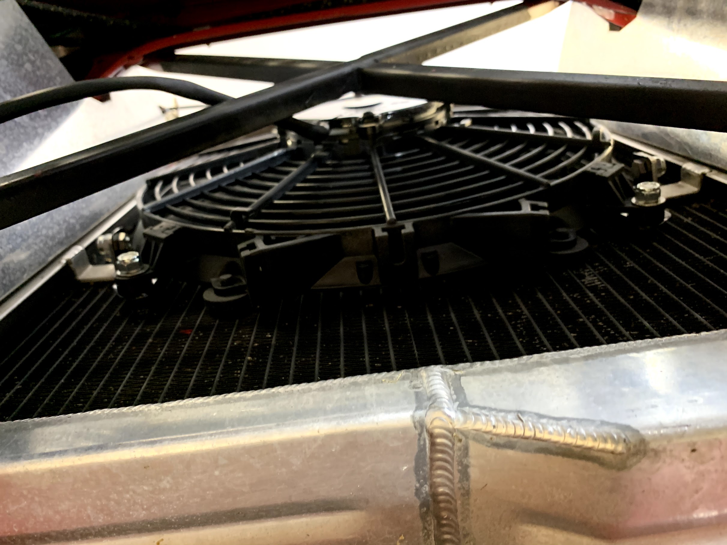
This is a view of the mounted fan from above:

Electric Fan Mounted Top View
And, from below:
Electric Fan Mounted Lower View
This image shows the lower RH bracket attached:
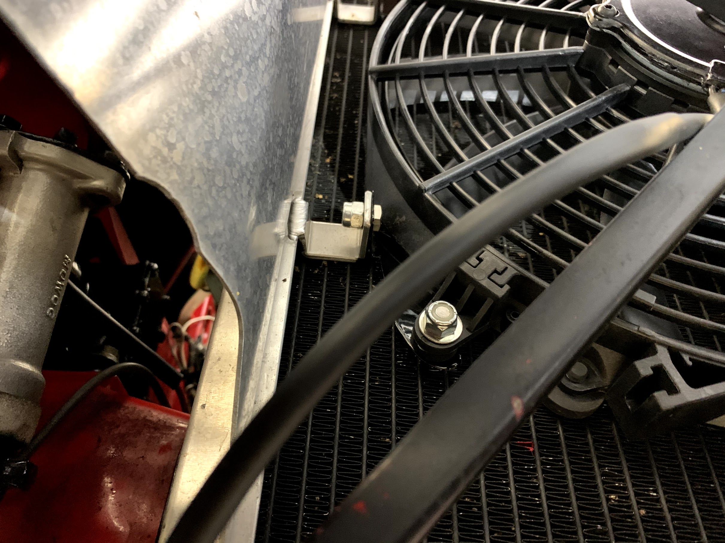
Electric Fan Mounted Lower RH Bracket
WIRING
Once the fan was installed, the next step was to install the wiring required. Before actually doing any wiring, I turned off the master switch in the boot of the car thereby removing power from the electrical system of the car.I used a Fan Relay Harness sourced from SPAL and followed the wiring schematic provided with the harness.
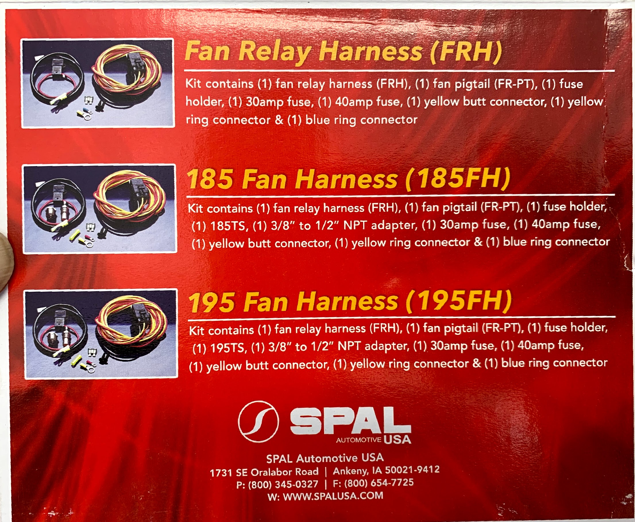
SPAL Fan Relay Harness
Since I am only using a toggle switch to turn the fan on/off and am not using a temperature controller I followed the dotted line wiring to the switch and skipped the sending unit wiring.
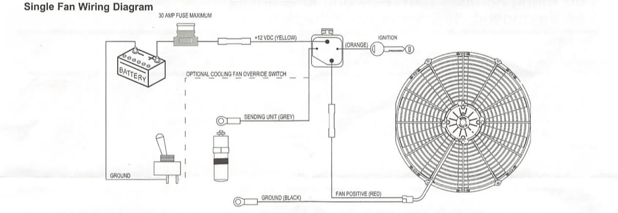
Fan Relay Harness wiring schematic
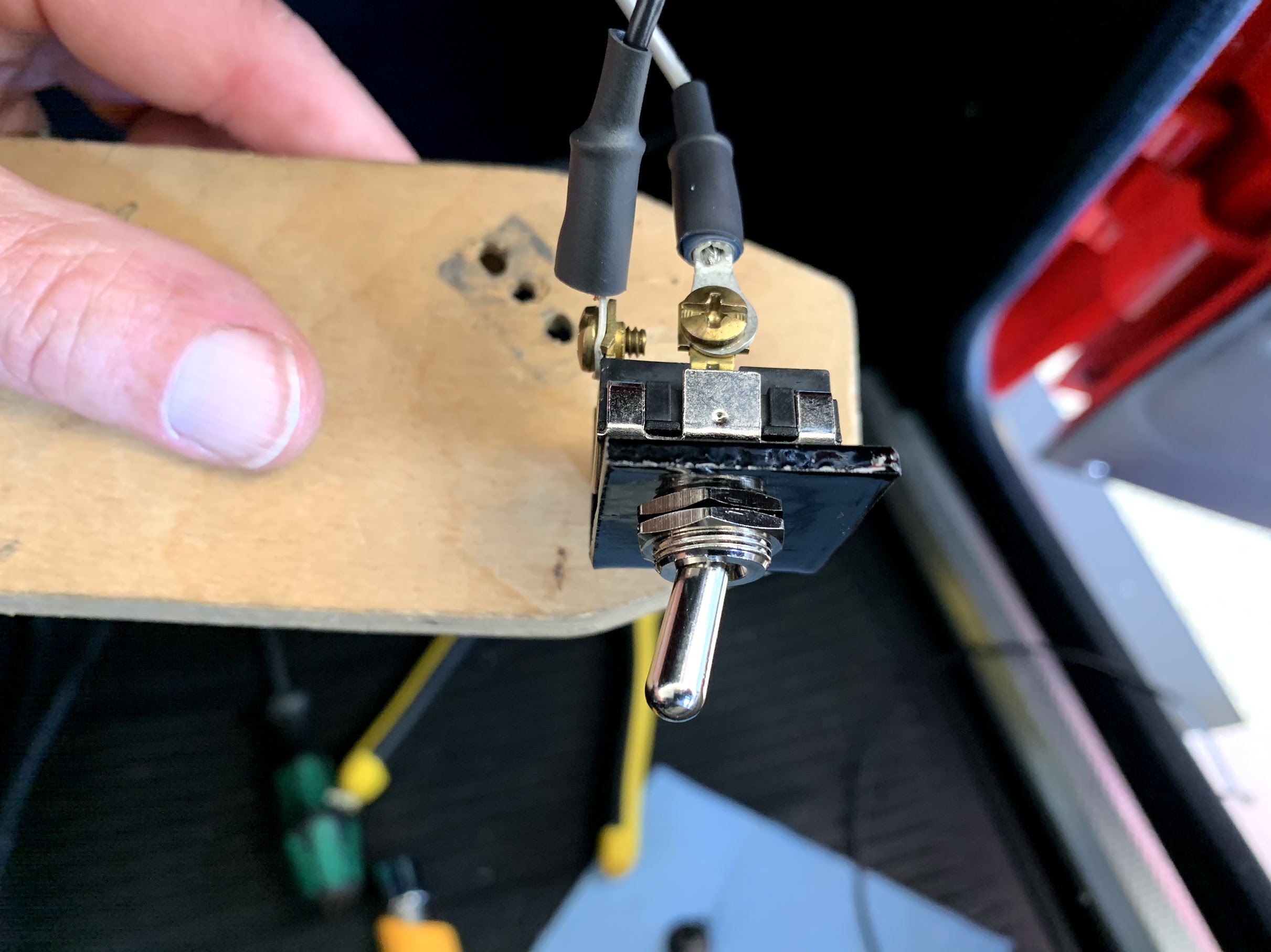
I used a toggle switch I had in my parts bin for this application.

Toggle Switch
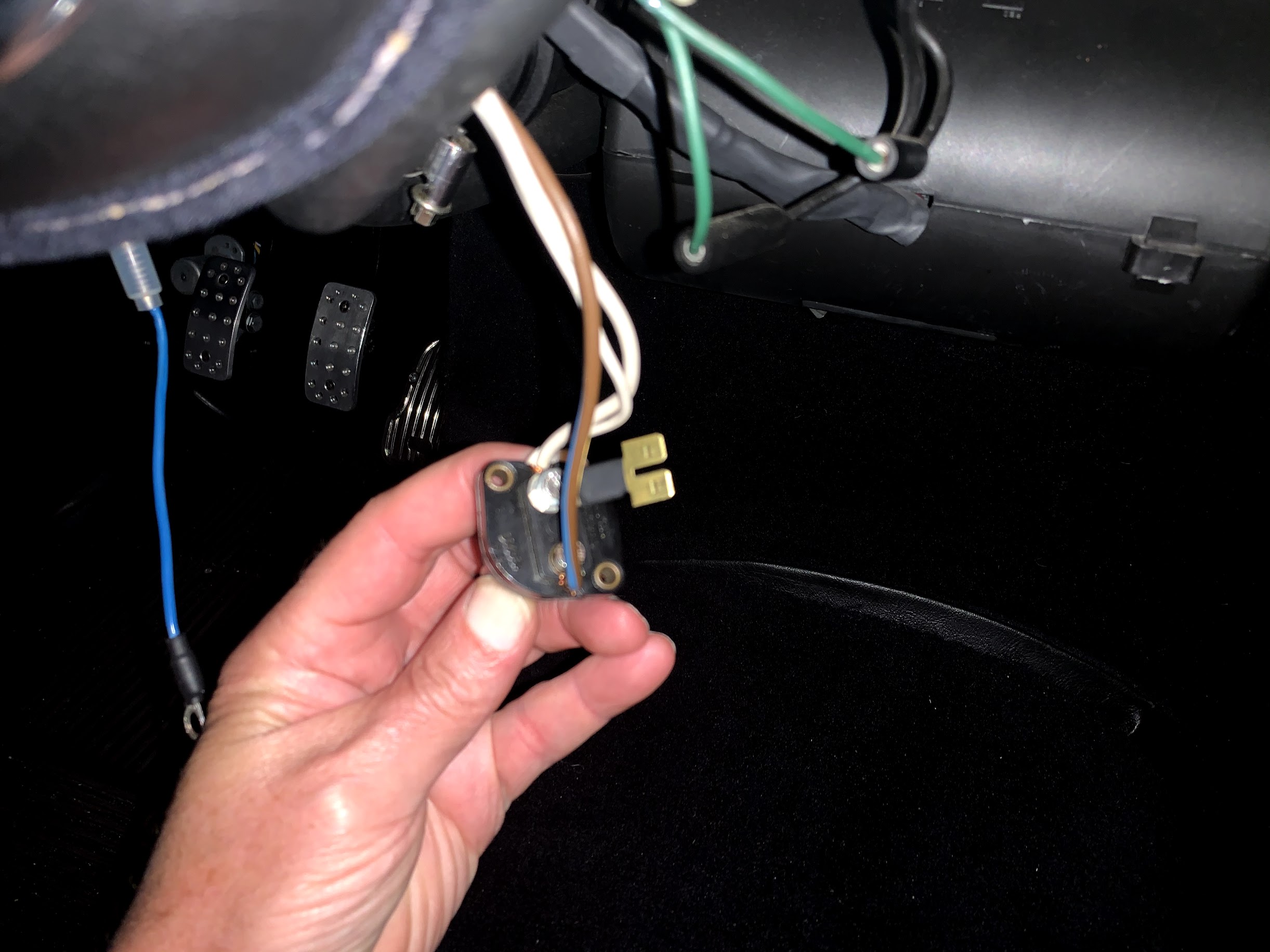
I mounted the relay on the inside of the firewall behind the parcel tray on the passenger side of the car. I wanted to hide the toggle switch from view so after making and painting a little metal bracket for the switch, I mounted it on the back side of the plywood used to secure the passenger “grab handle.”
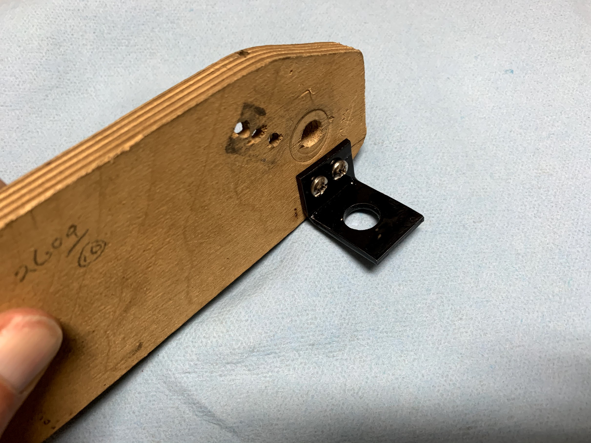
Mounted toggle switch bracket
Toggle switch mounted
This made it easy to attach the grey wire from the relay to the toggle switch and I made a black wire for the ground connection from the switch to a screw on the inside of the firewall.
I ran the orange wire to the ignition switch so that the relay would be energized when the ignition switch is in the “on” position. The mounting posts on the ignition switch can get a little crowded so I took advantage of a “terminal splitter” I had in my parts bin that made connecting the wiring much easier.
Terminal splitter
The yellow and red wires from the relay exited the interior through an available rubber grommet on the firewall into the engine compartment. The yellow wire, after splicing in the 30 amp fuse, was then connected to the starter solenoid as a battery power source.
The red wire followed other wiring down the diagonal RH frame brace to the front of the car where it attached to the fan wiring pigtail. The red wire connects to the black wire on the pigtail, because the wiring was reversed when the fan was converted from a “puller” to a “pusher.” I then made a short black wire to connect to the blue wire on the fan pigtail and attached it to a ground screw near the grille of the car.
I then turned on the master electrical switch in the boot, and turned the key to the “on” position of the ignition switch, and flipped the toggle switch to the fan. I immediately heard the whine of the new fan and I knew I was in business!
One more Healey task completed!!