Brake Servo & Hydraulics
Brake Servo and Hydraulics Schematics

- Brake Servo & Piping


- Reservac, Stoneguard & Piping

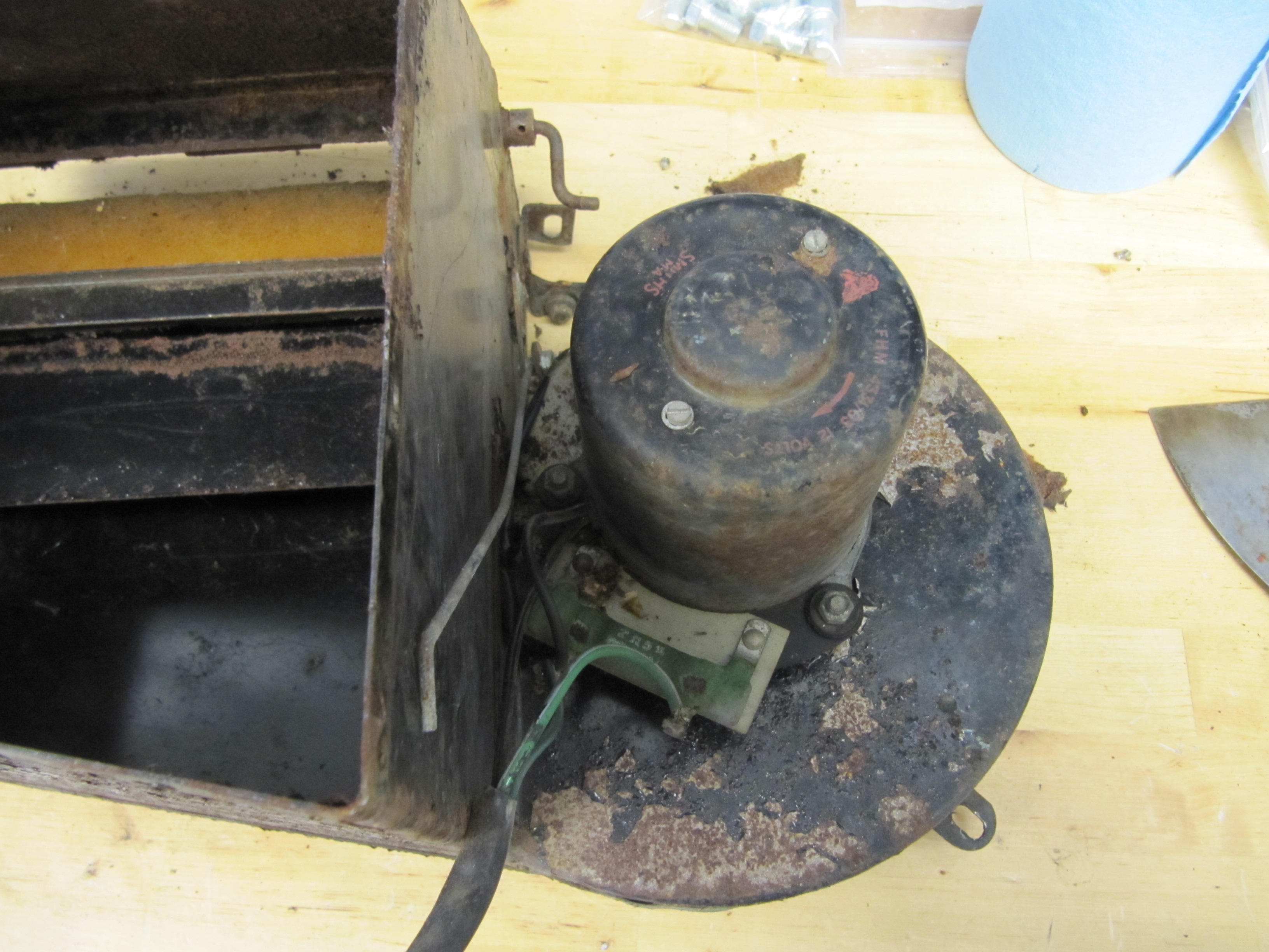
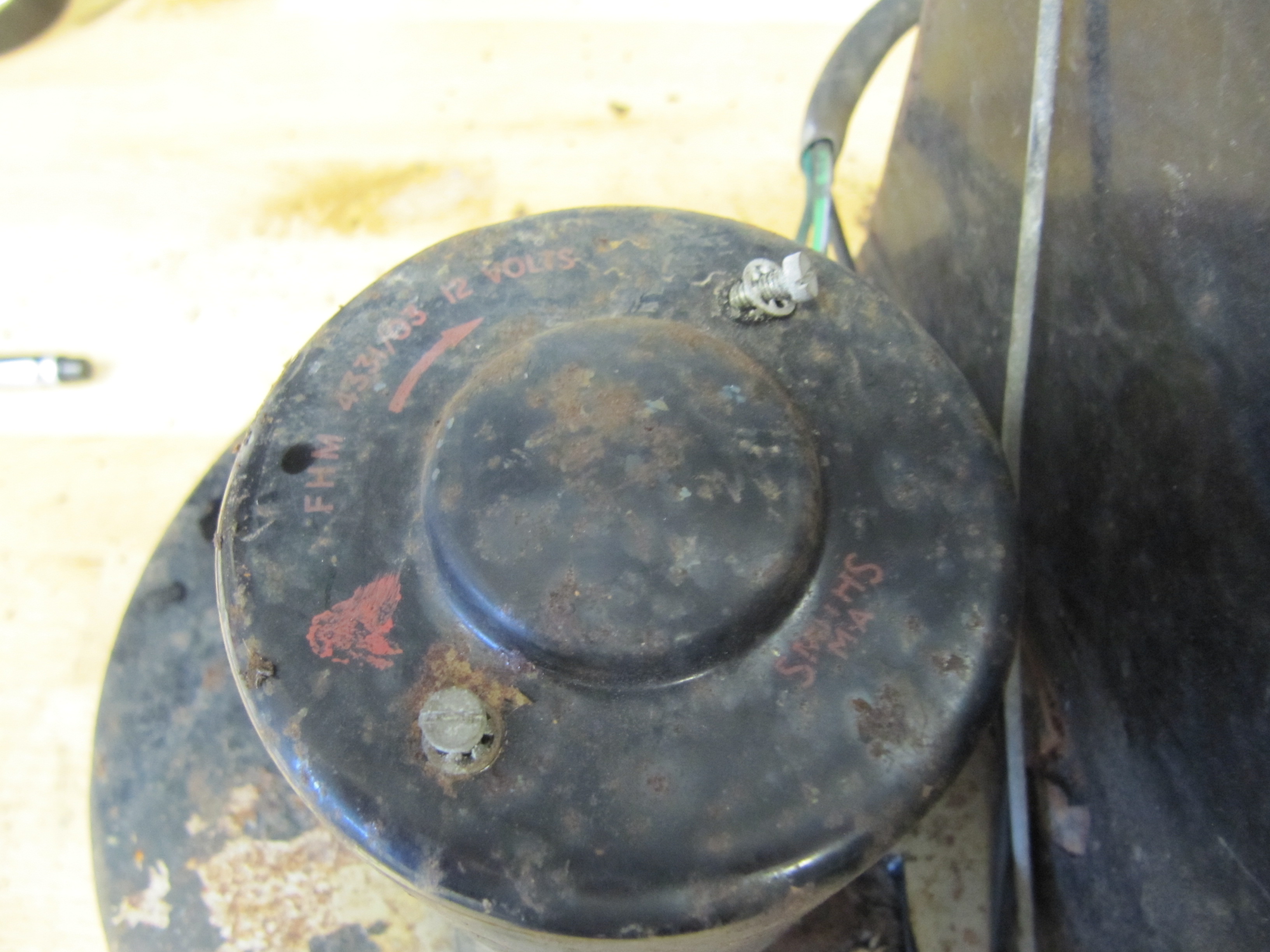
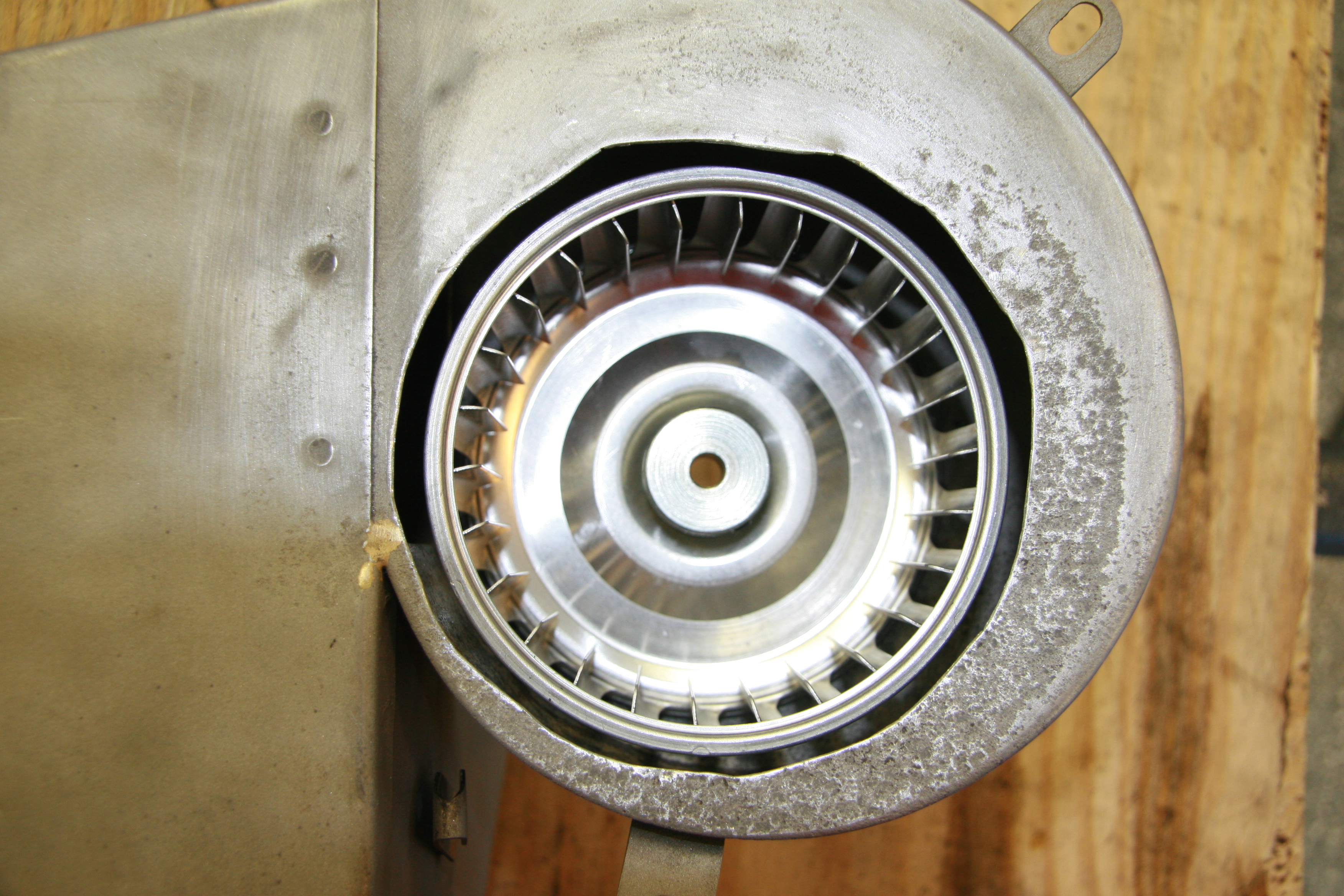
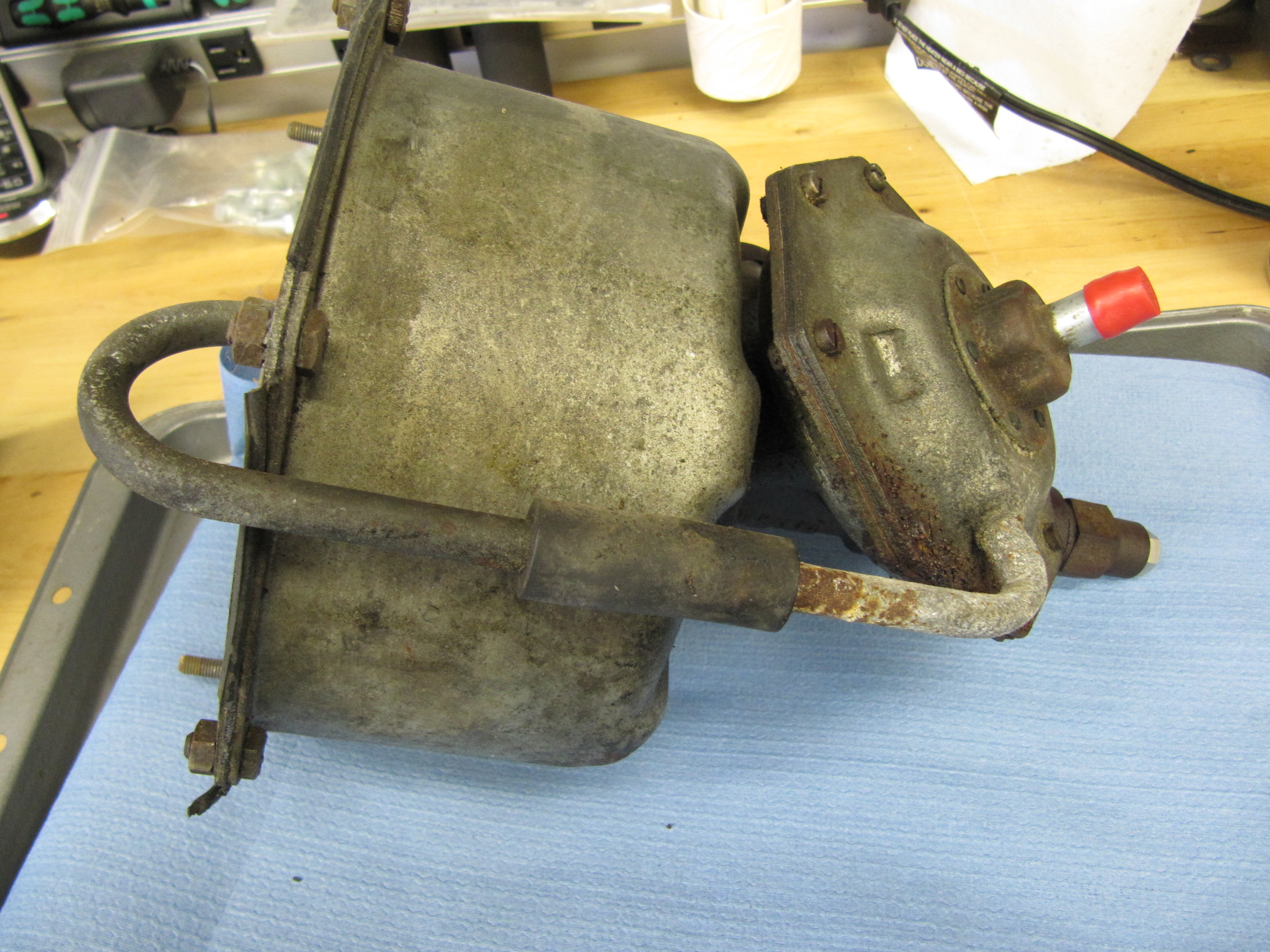
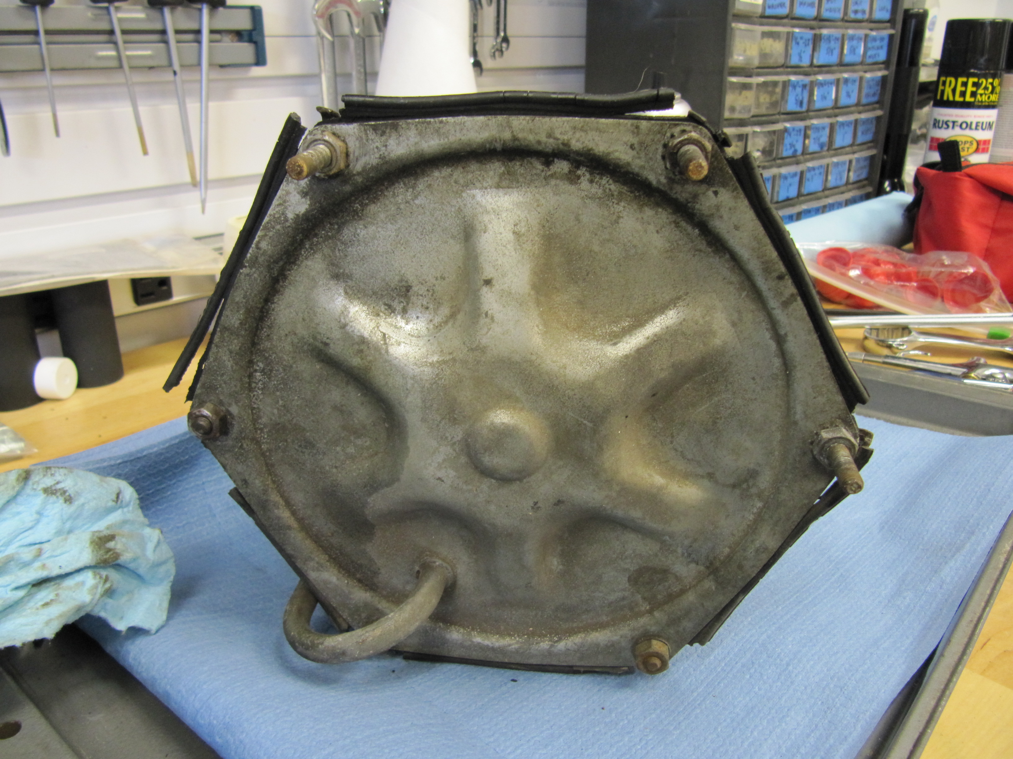
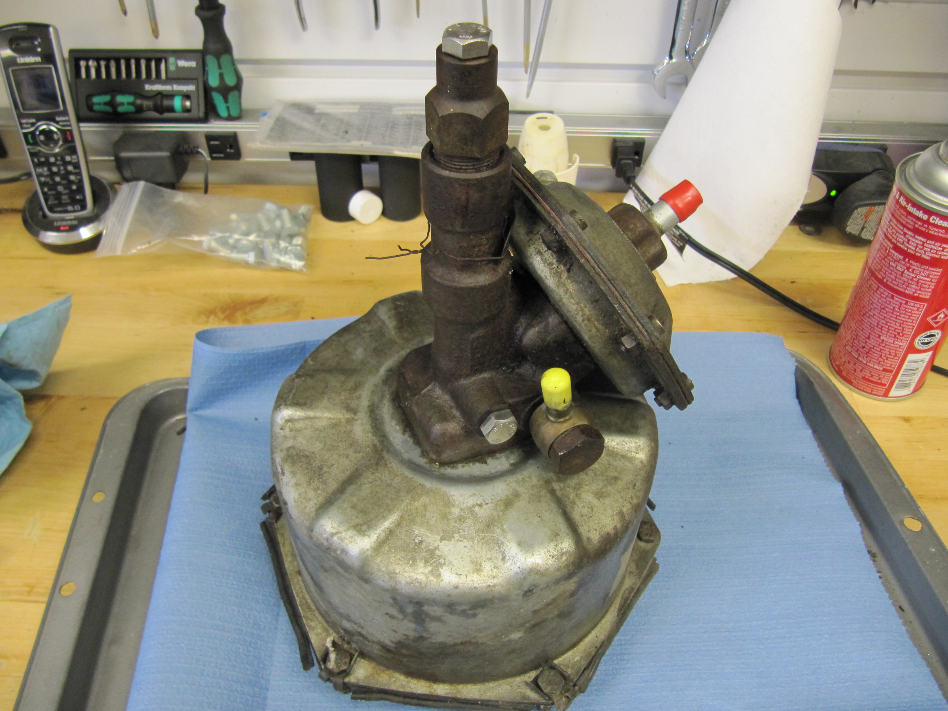
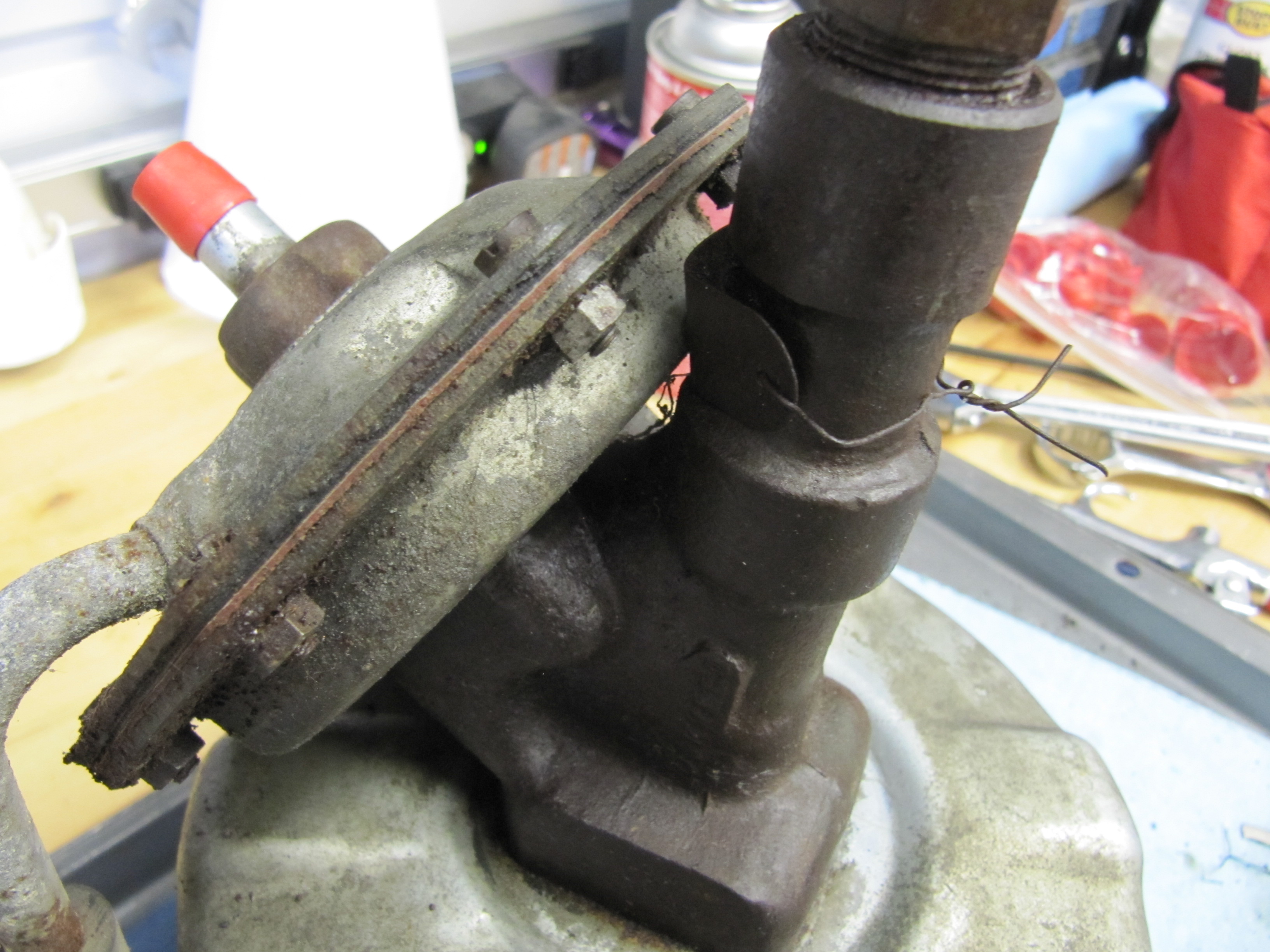
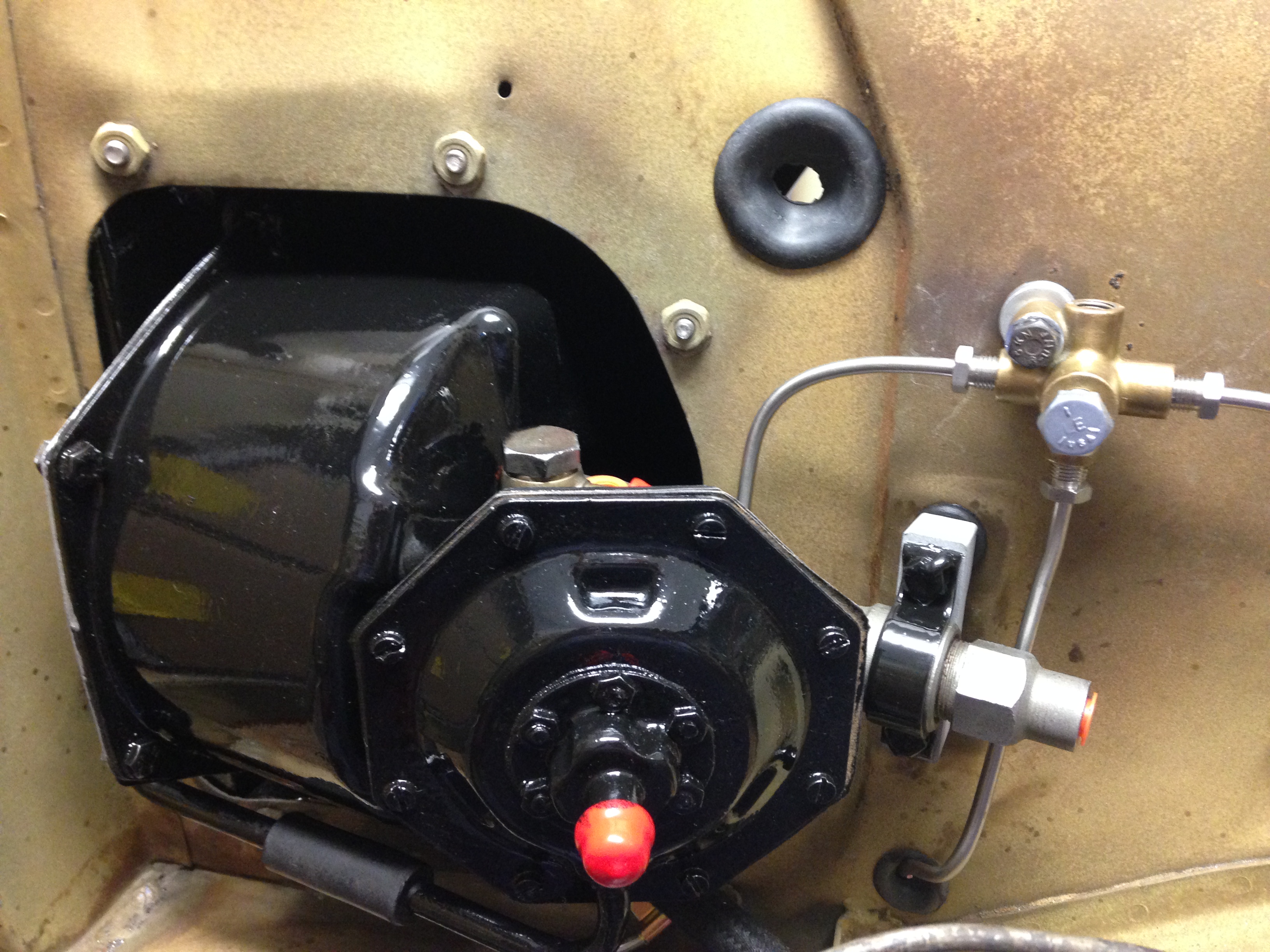
Brake Servo
The MK2 uses a Lockheed 6 7/8″ brake servo. I decided to have my servo rebuilt rather than purchasing a new unit. Rich Chrysler, an Austin Healey friend always swore by John Stuart Power Brake in Ontario so I decided to use them to refurbish the servo and to sleeve (with Stainless Steel) the Girling 875 master cylinder.
Brake Servo
Brake Servo
Brake Servo
Brake Servo
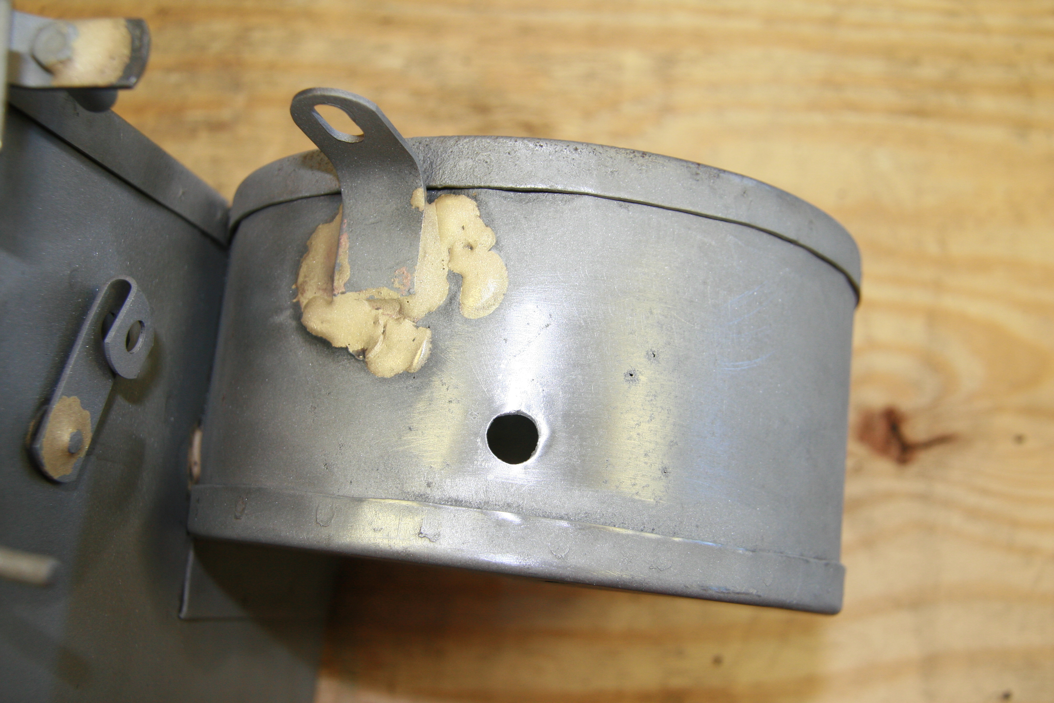
Rebuilding the servo and master was not an inexpensive proposition! But both components have been bench tested and are now ready for installation.
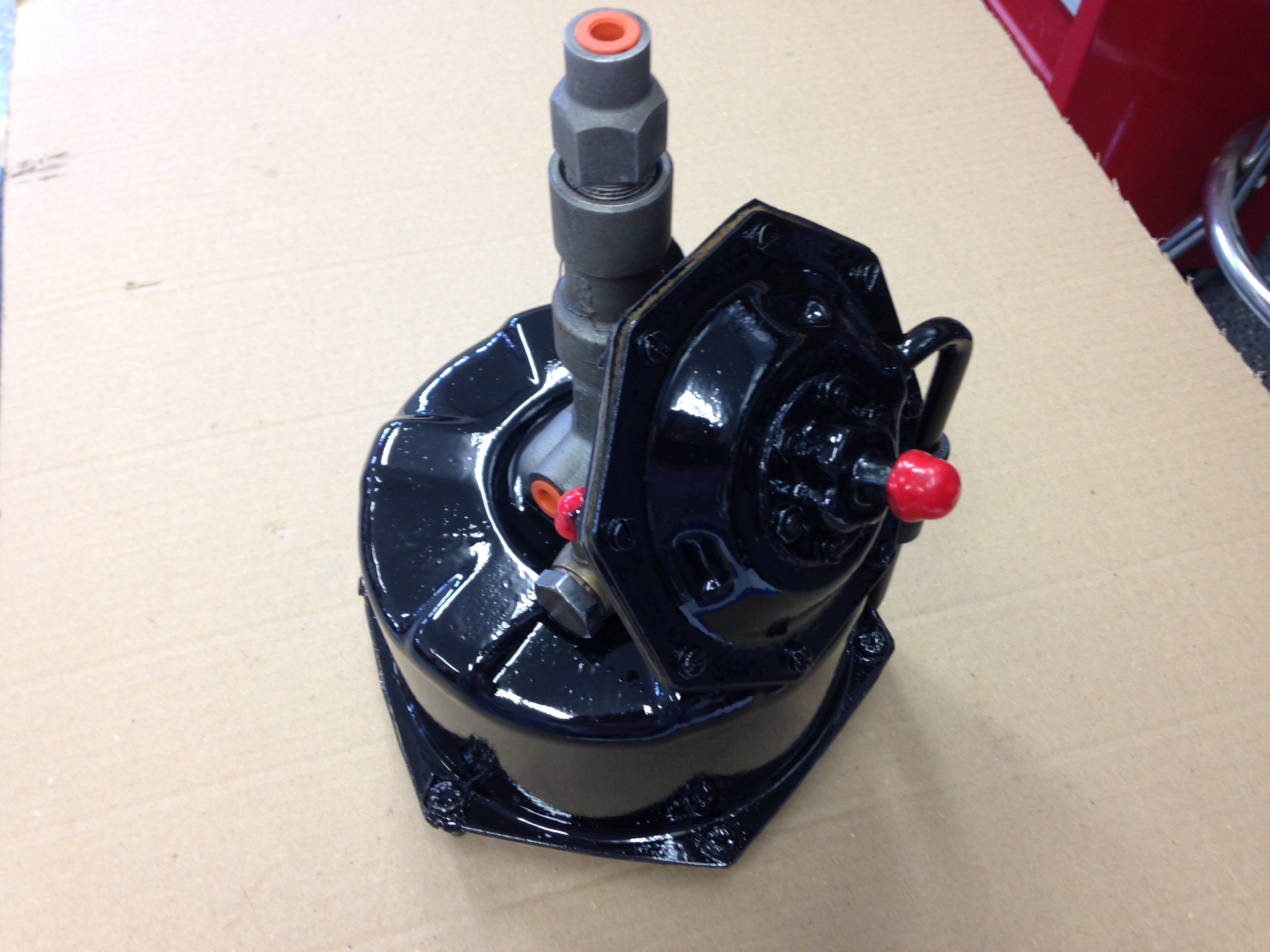
Brake Servo Painted for Installation
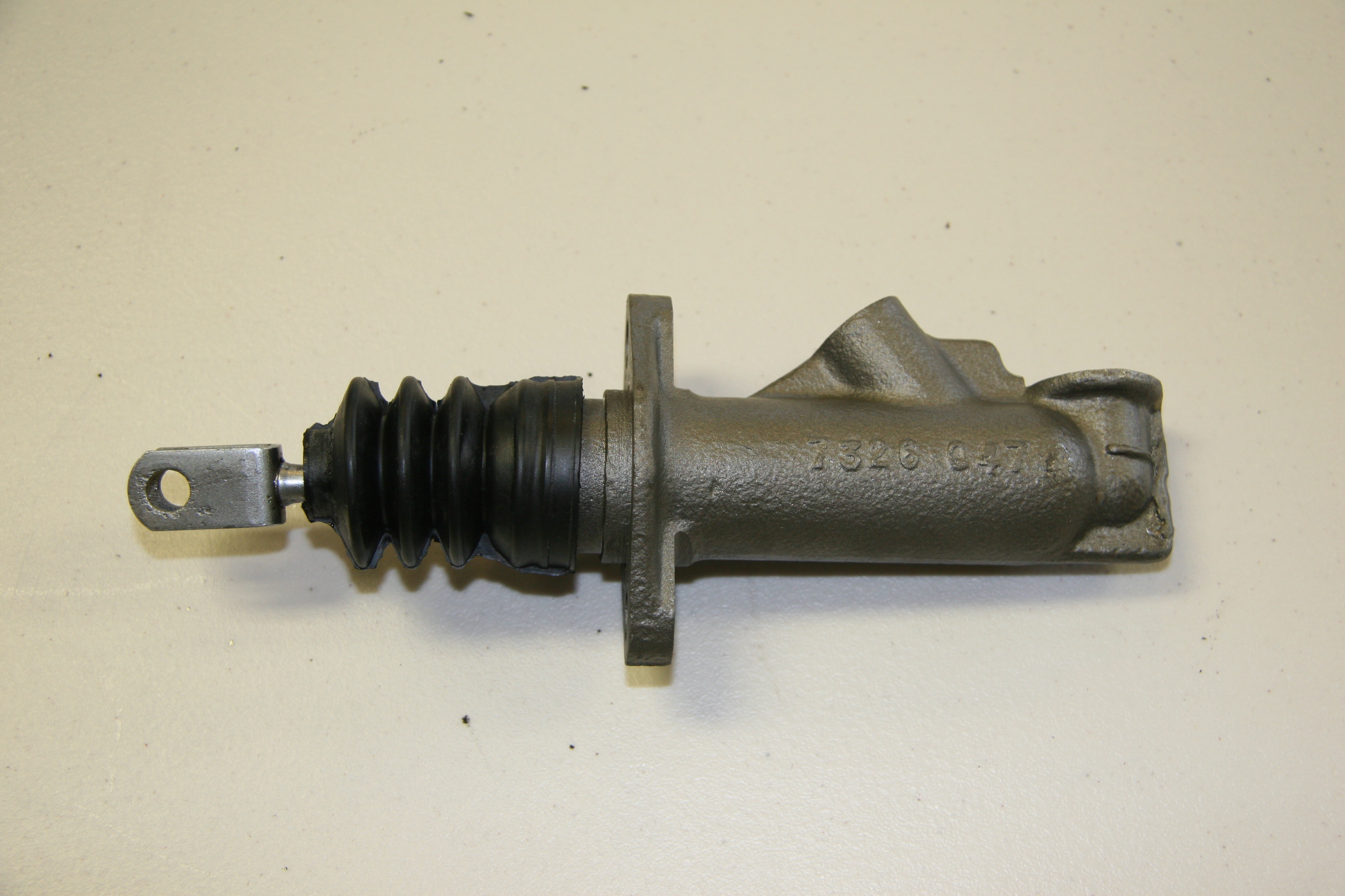
Rebuilt Master

Brake Servo Painted for Installation
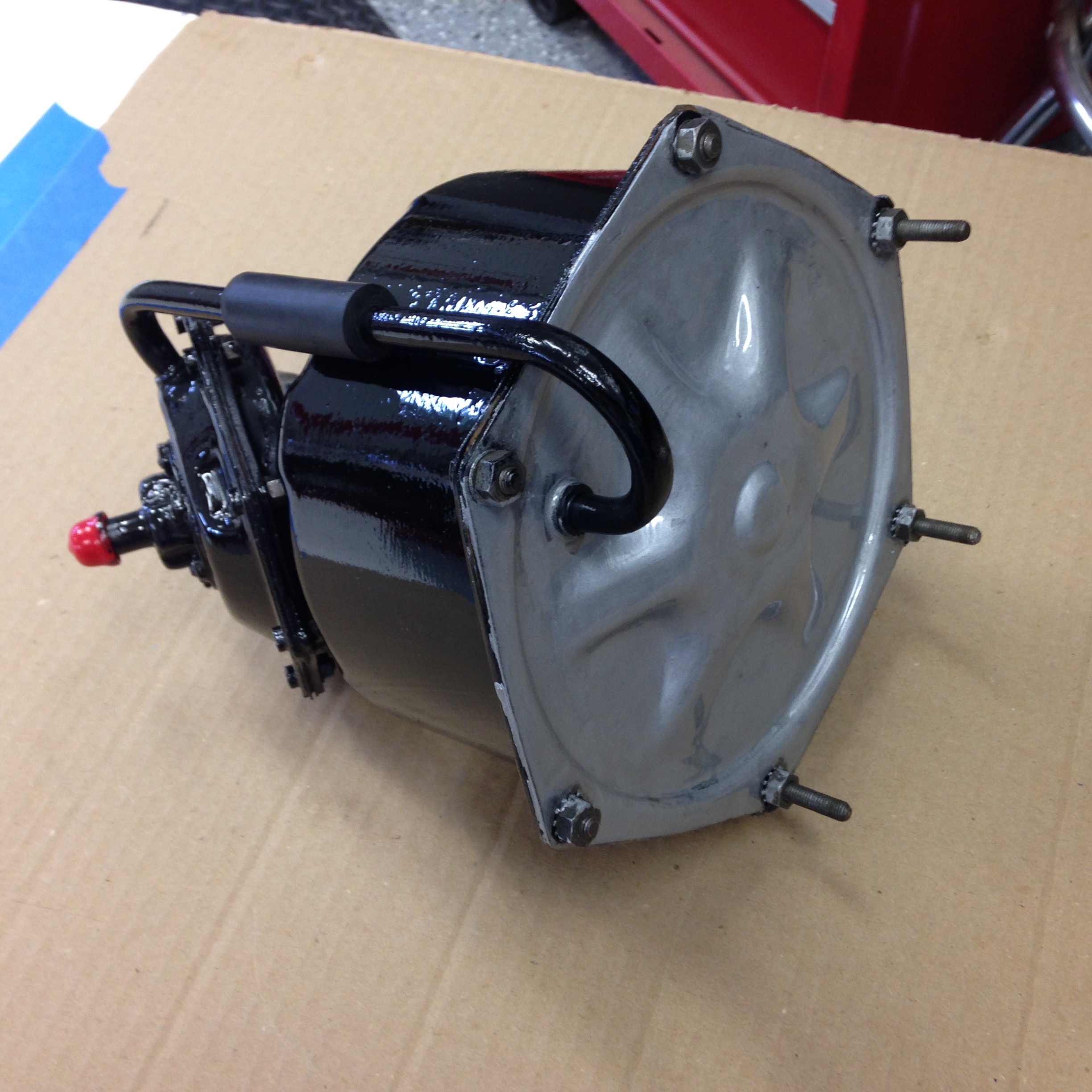
Brake Servo Painted
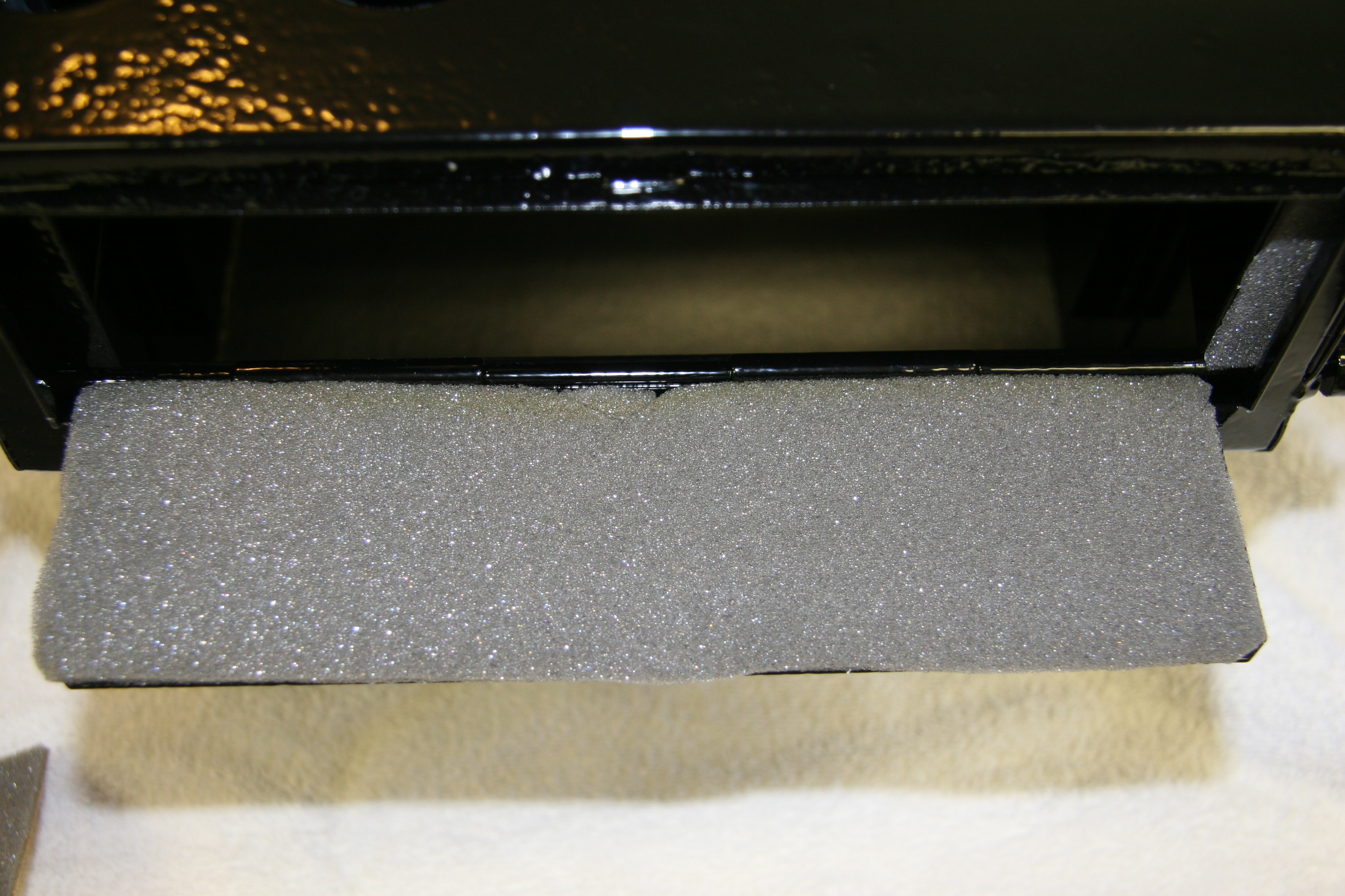
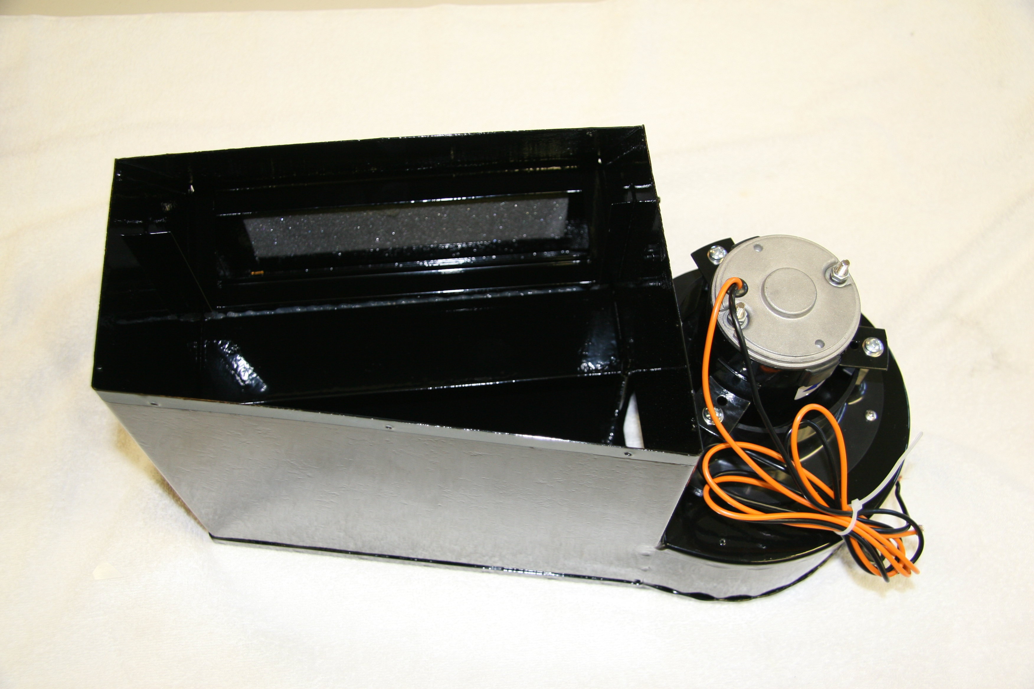
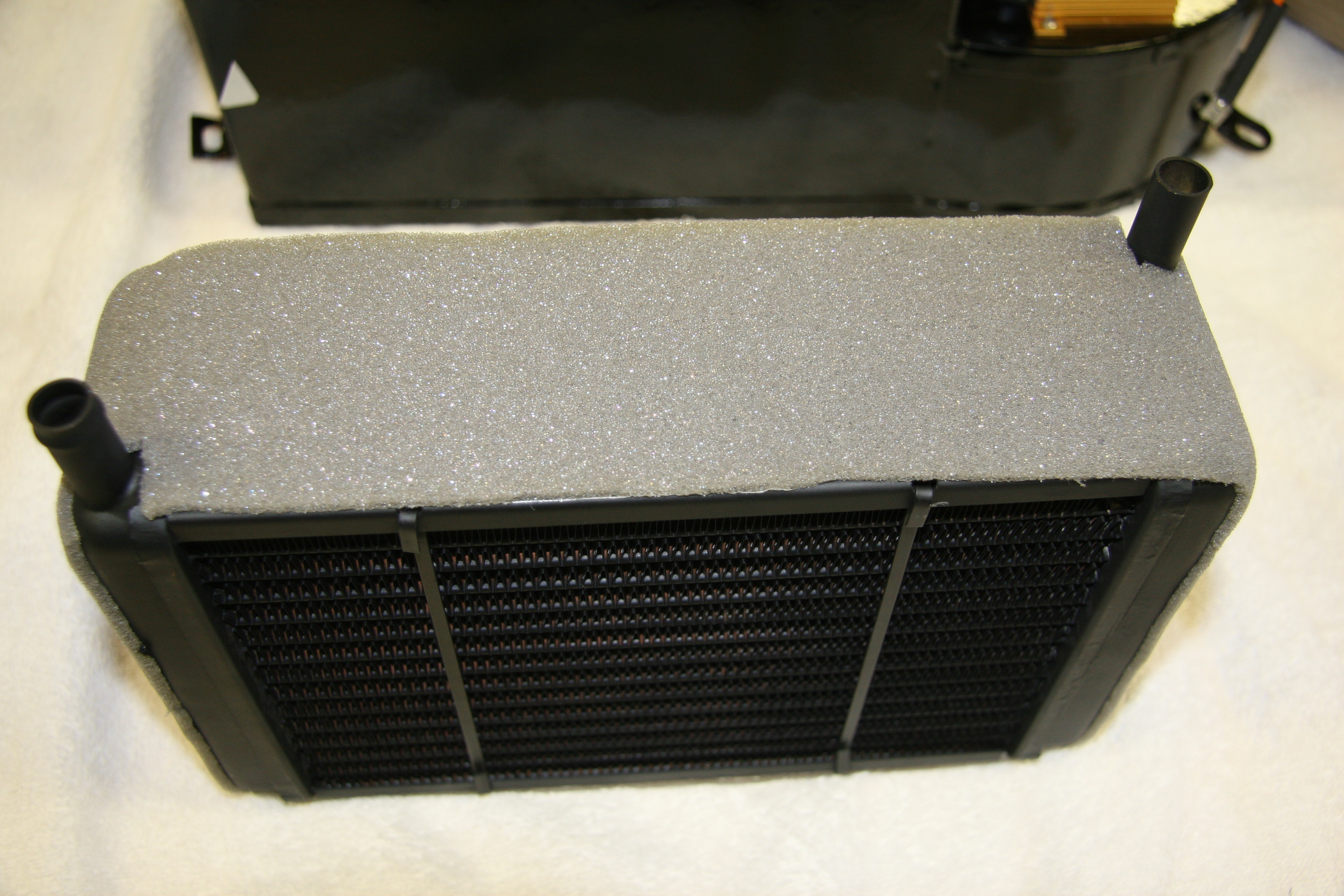
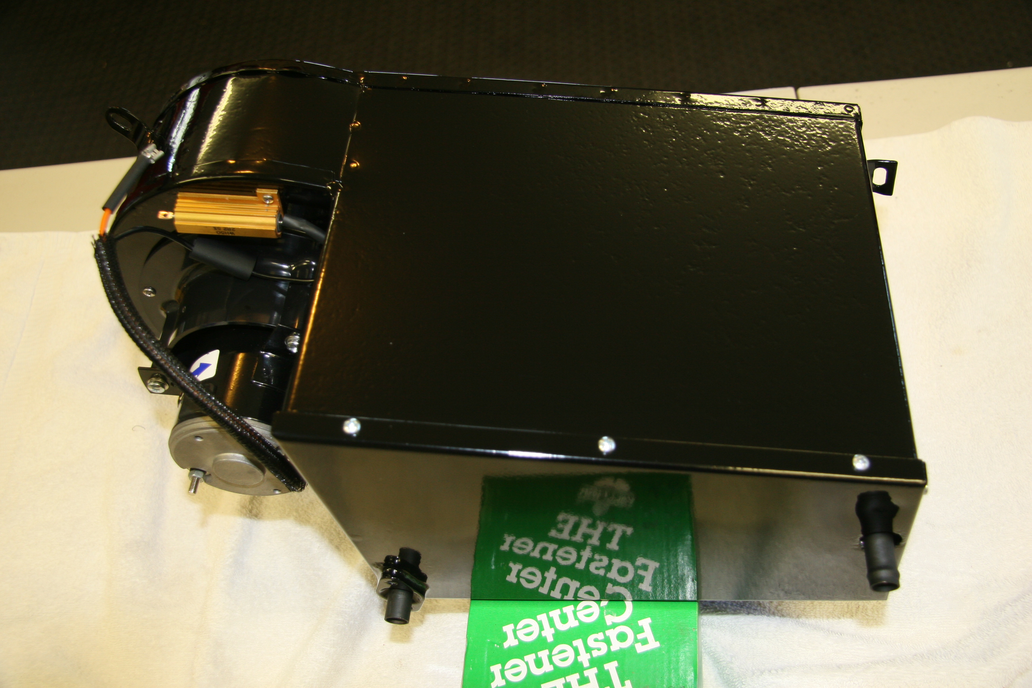
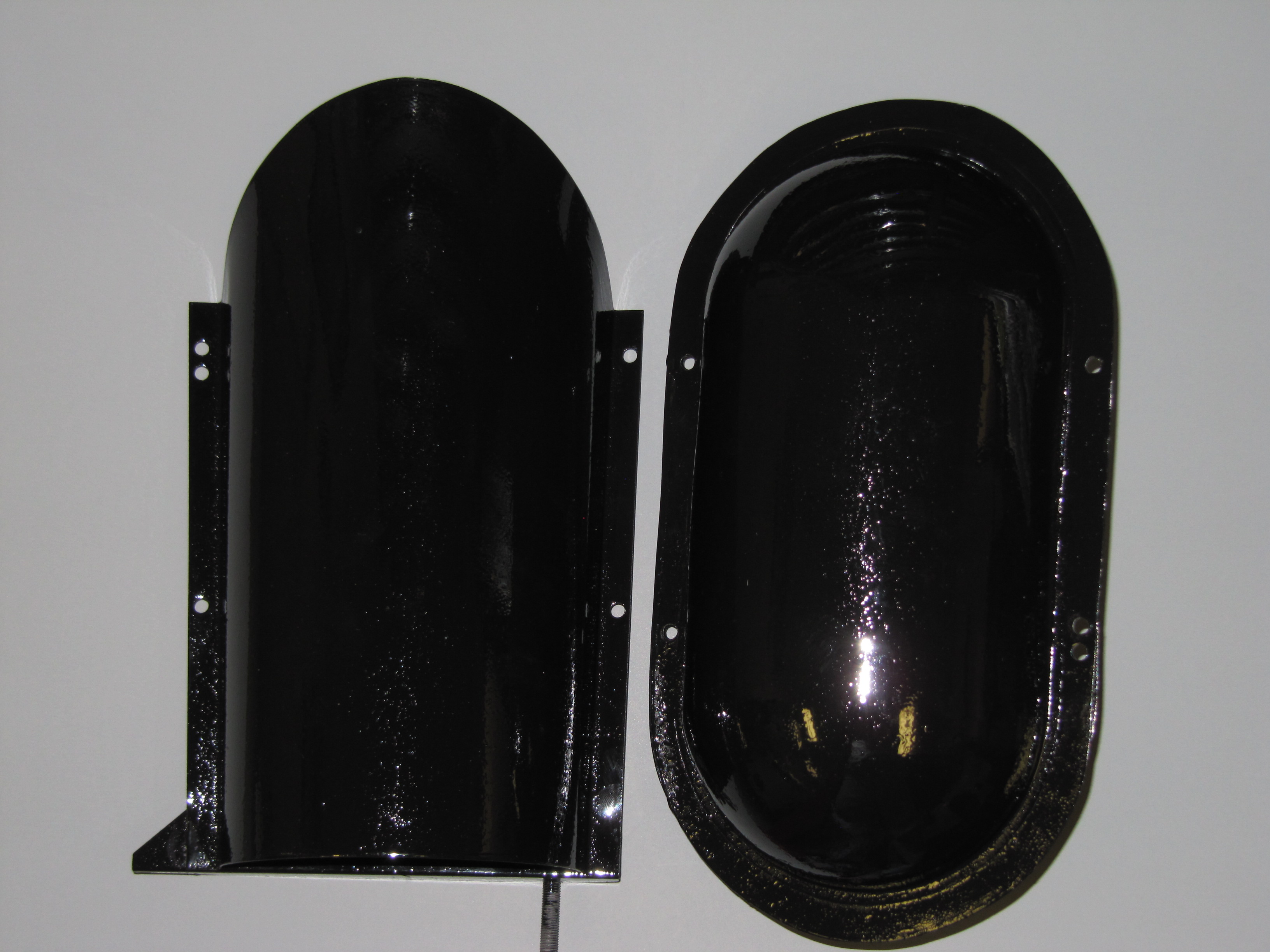
Stoneguard and Reservac Tank
I decided to go with a brand new Stoneguard and Reservac Tank purchased from SNG Barrett. I may change the color later but I decided to paint these two components with gloss black POR 15. The tank was fastened to the stoneguard with four hex head #10 -32 x 5/8″ bolts, shakeproof washers, and hex nuts. The support rod attaches to the stone guard/tank assembly with a #10 hex nut and washer. The original check valve is shown below but I will replace it with a new device.
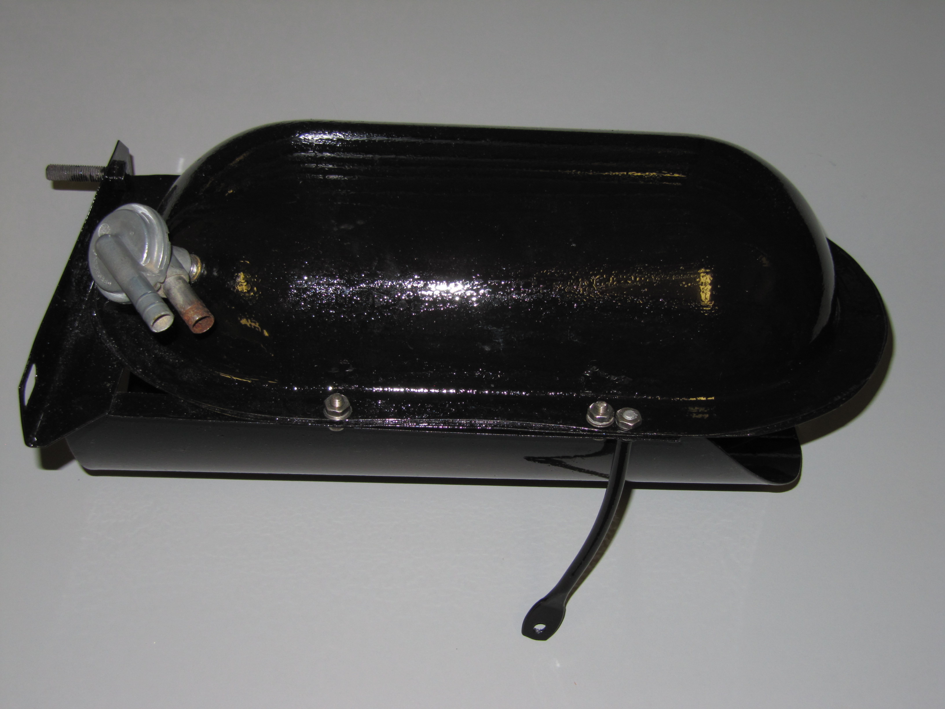
Reservac Tank Assembly
Stoneguard & Reservac Tank

Stoneguard & Reservac Tank
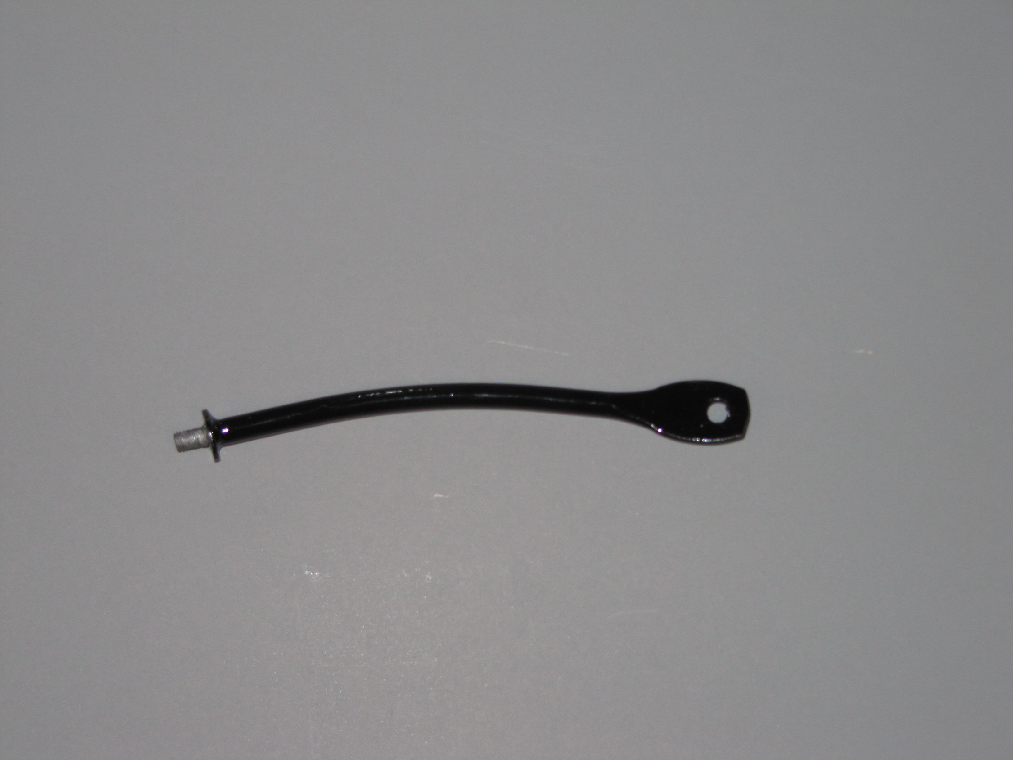
Rod for Reservac Tank
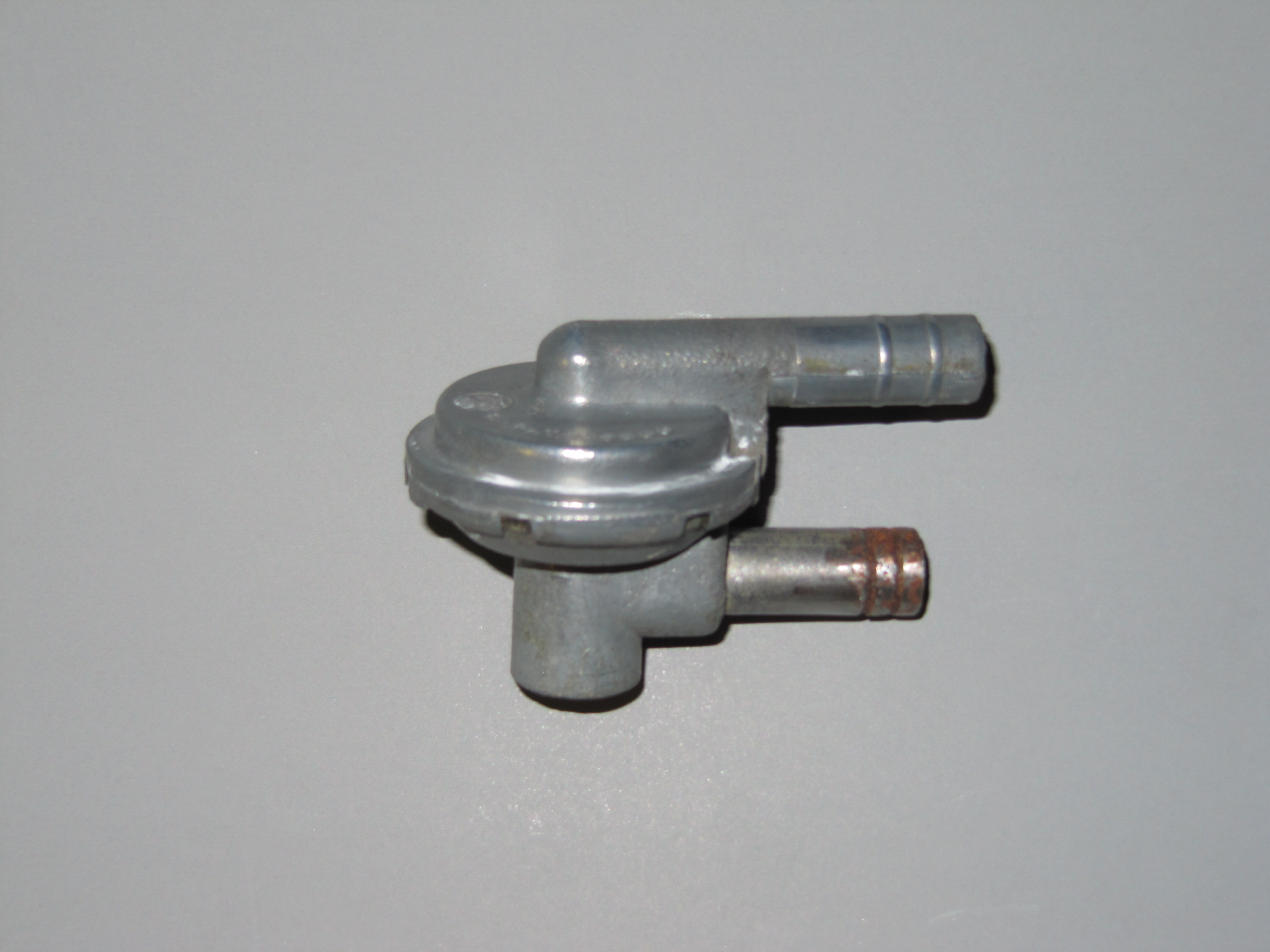
Reservac Check Valve
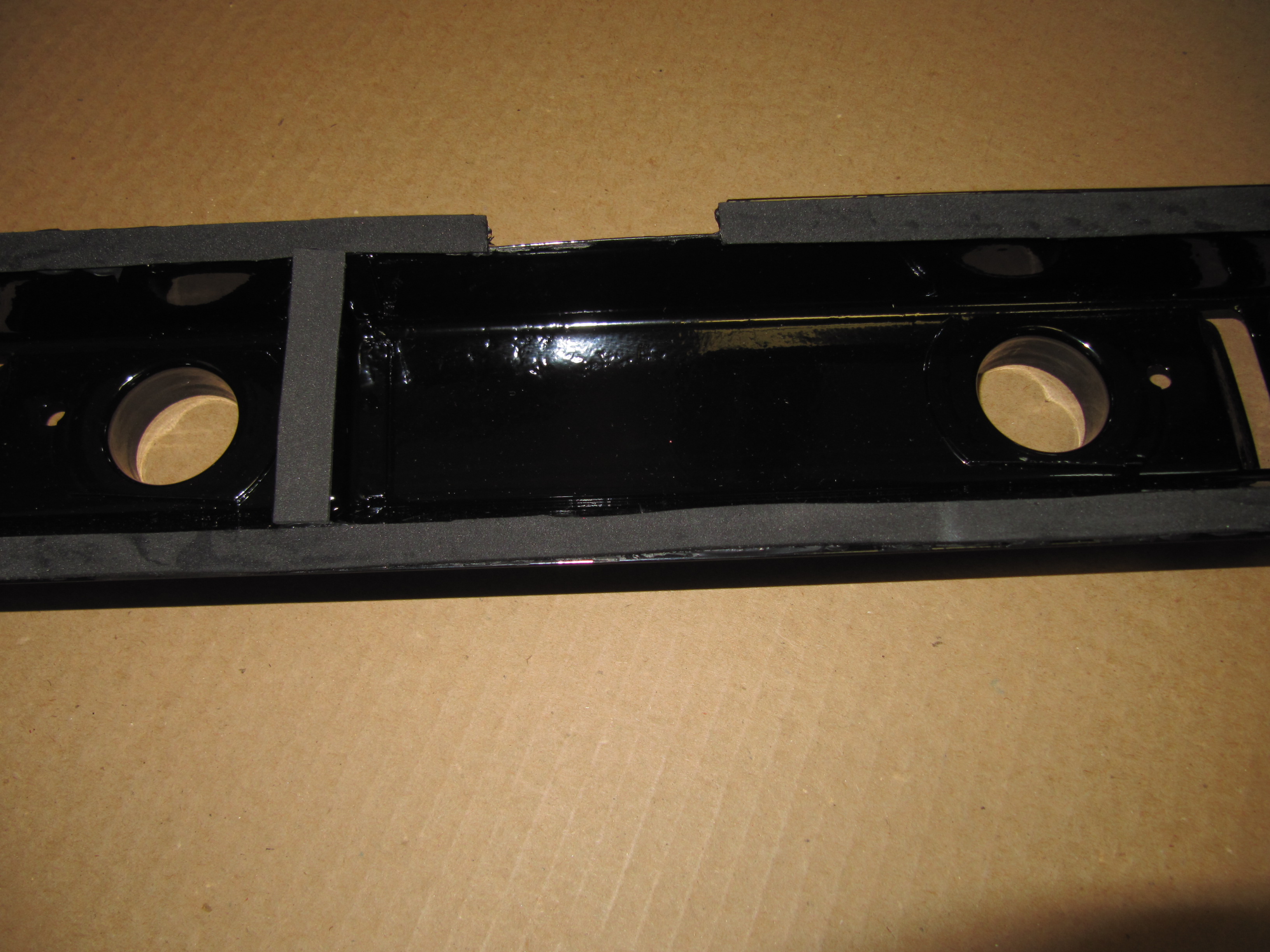
Servo Mounting
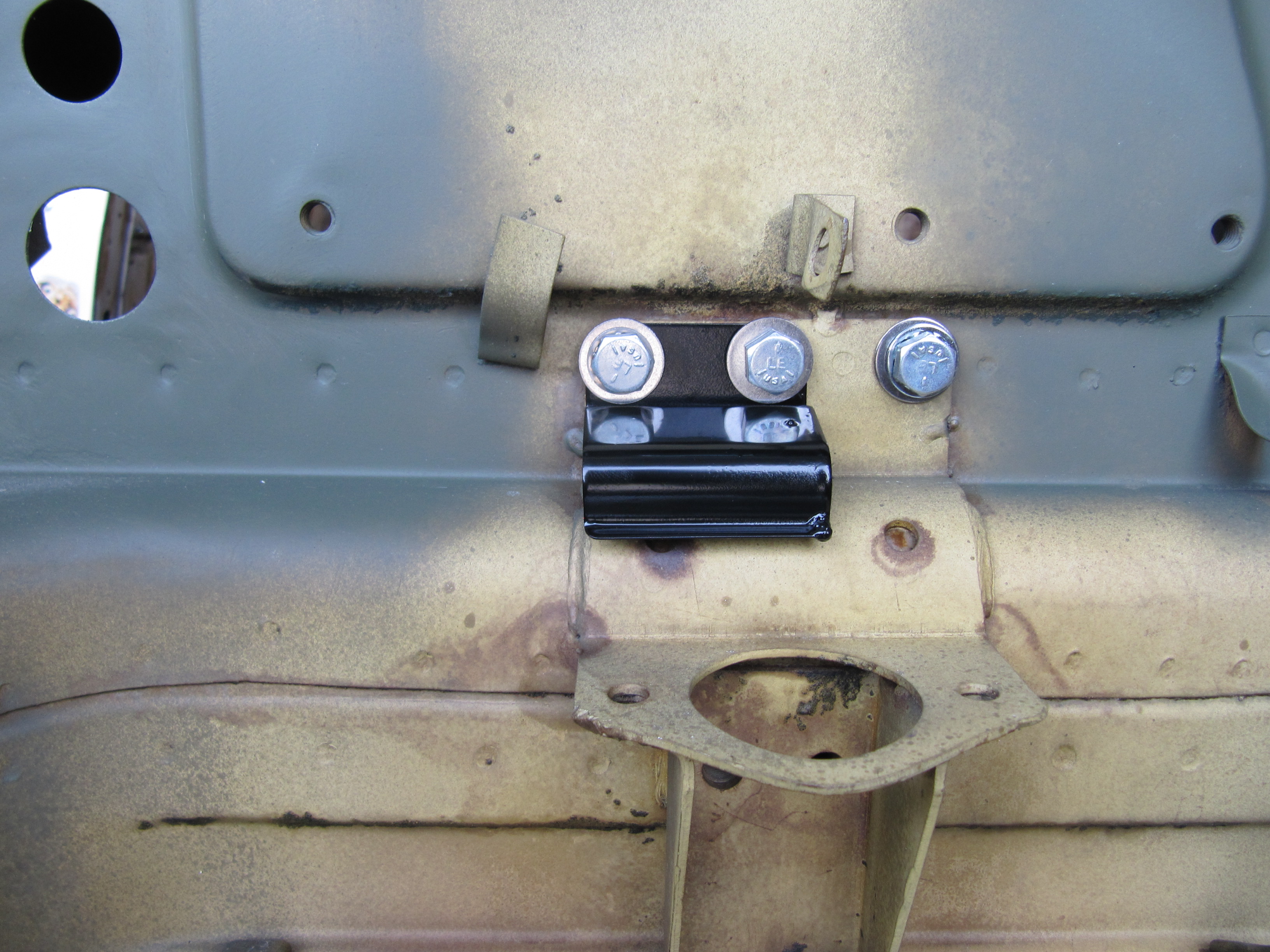
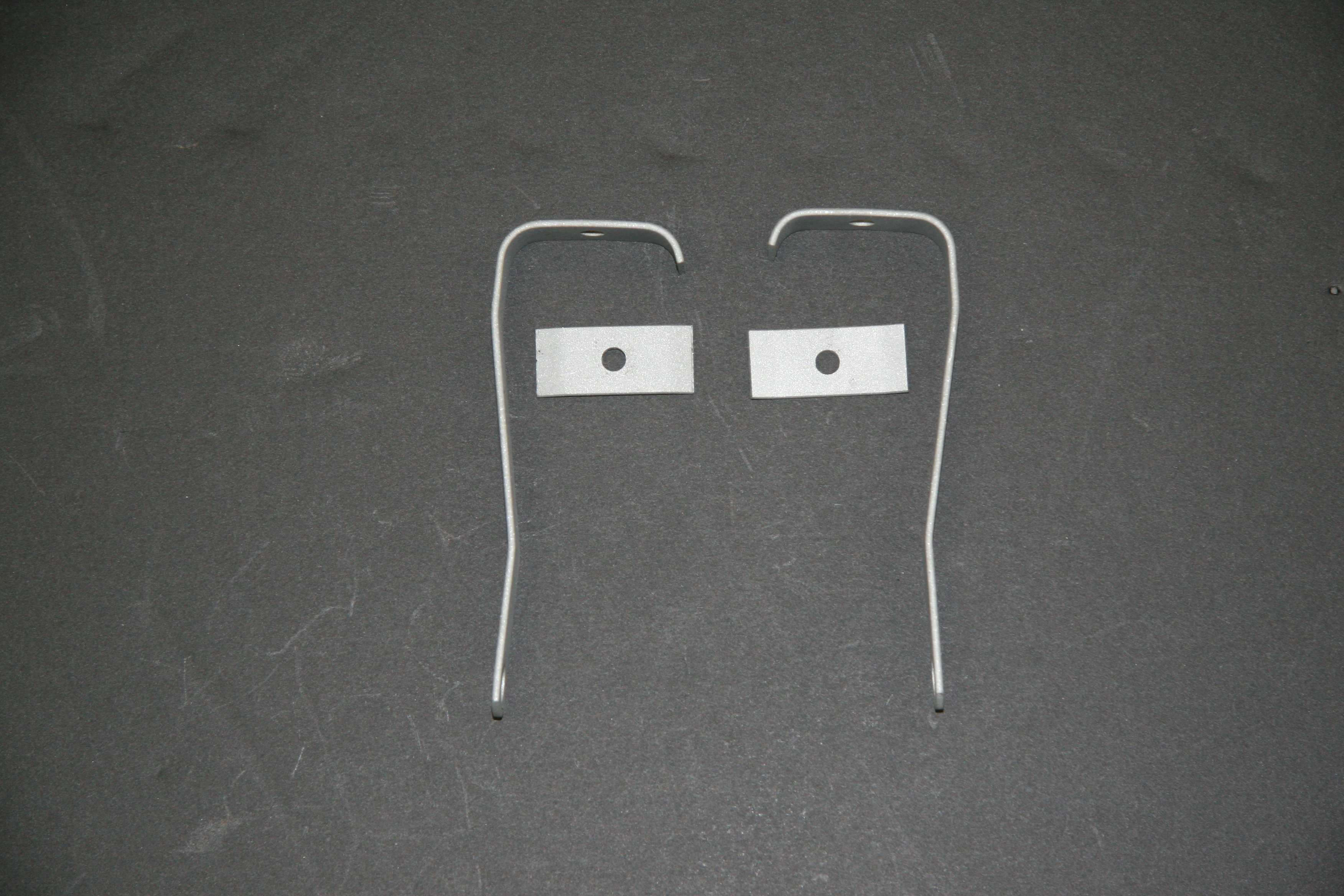
The Support Block and Clamp for Mounting of Servo to the Front Wing Valance is comprised of the curved clamp with two 1/4″ – 28 x 1″ hex head bolts spot welded to the clamp connected through the aluminum block, a rubber grommet with a metal spacer into the valance and two hex nuts with shakeproof washers.
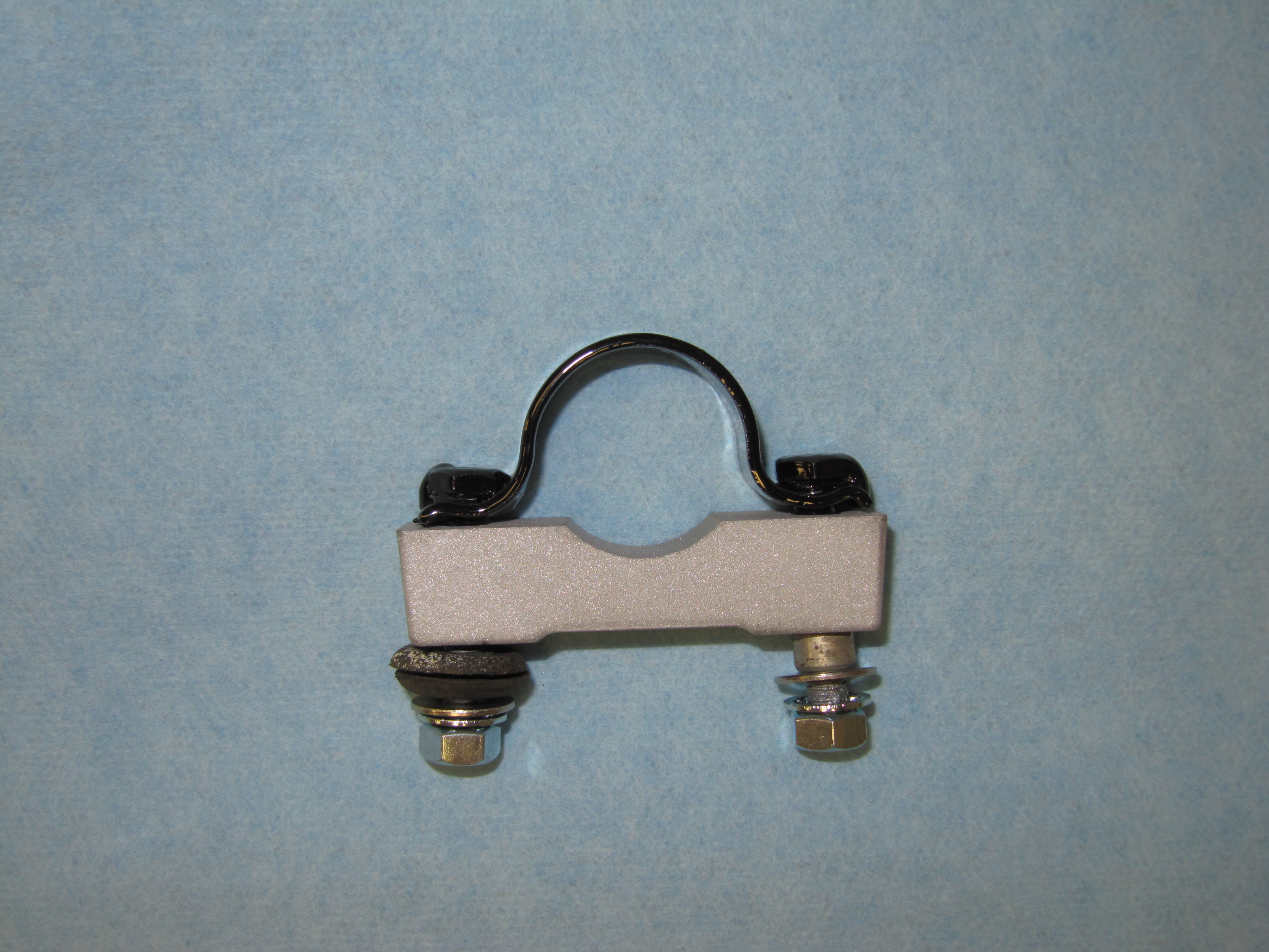
Support Block & Clamp
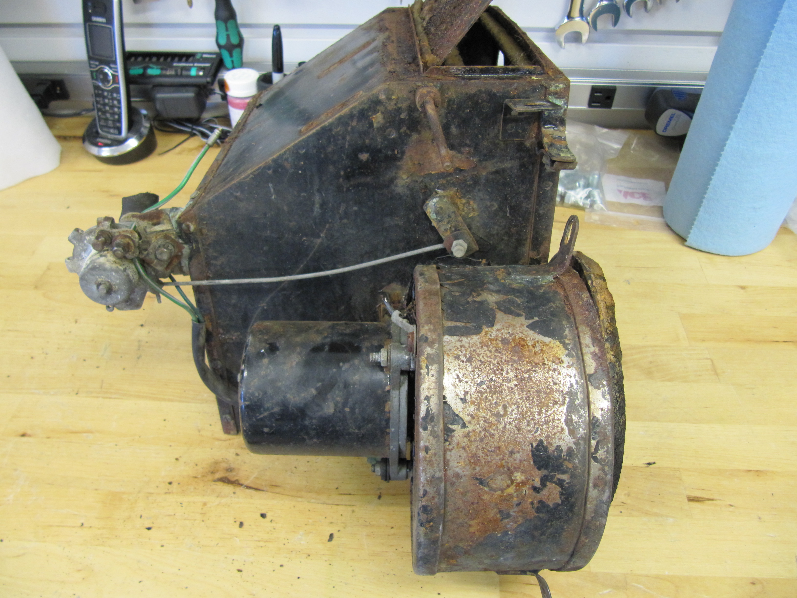
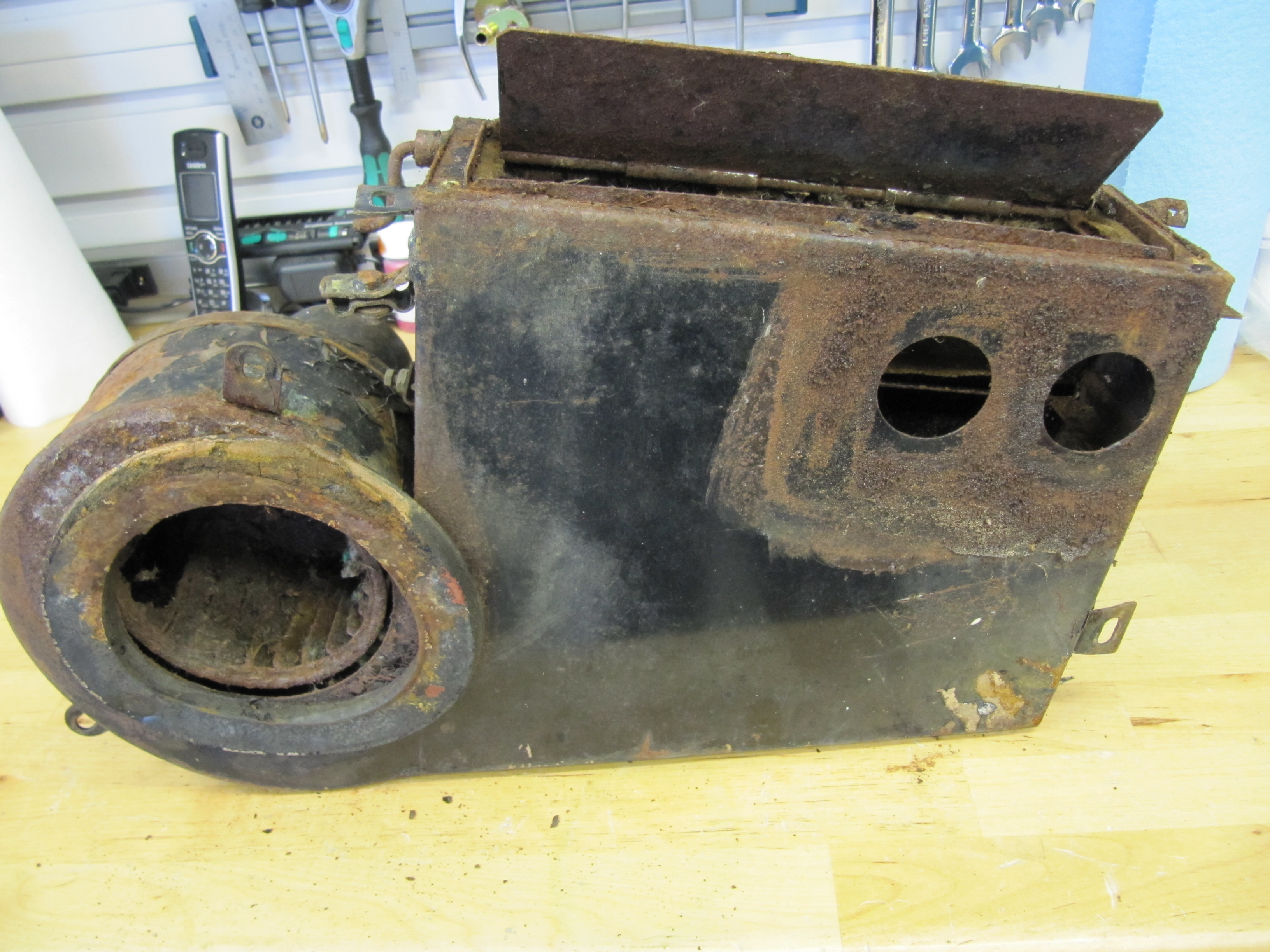
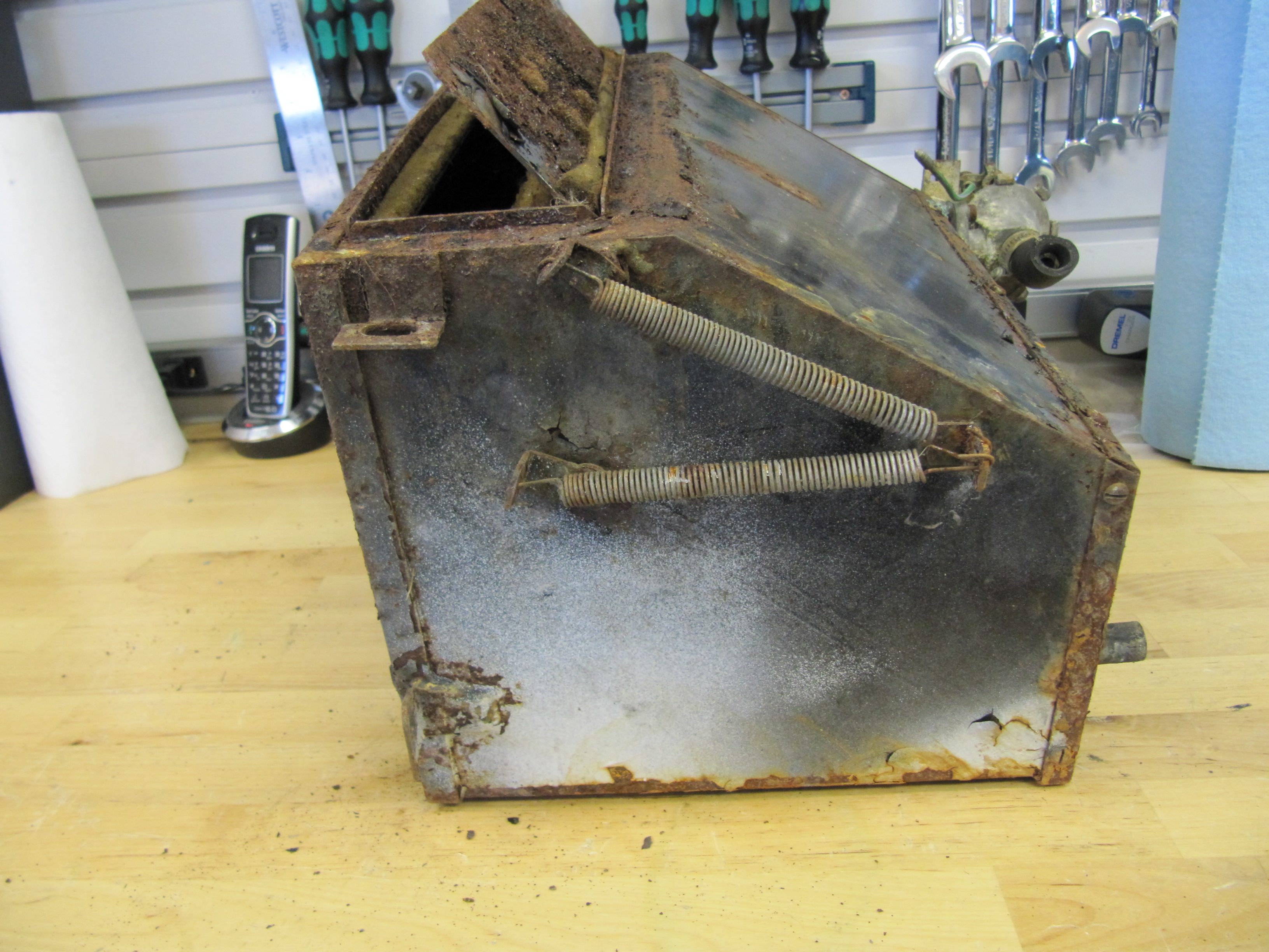
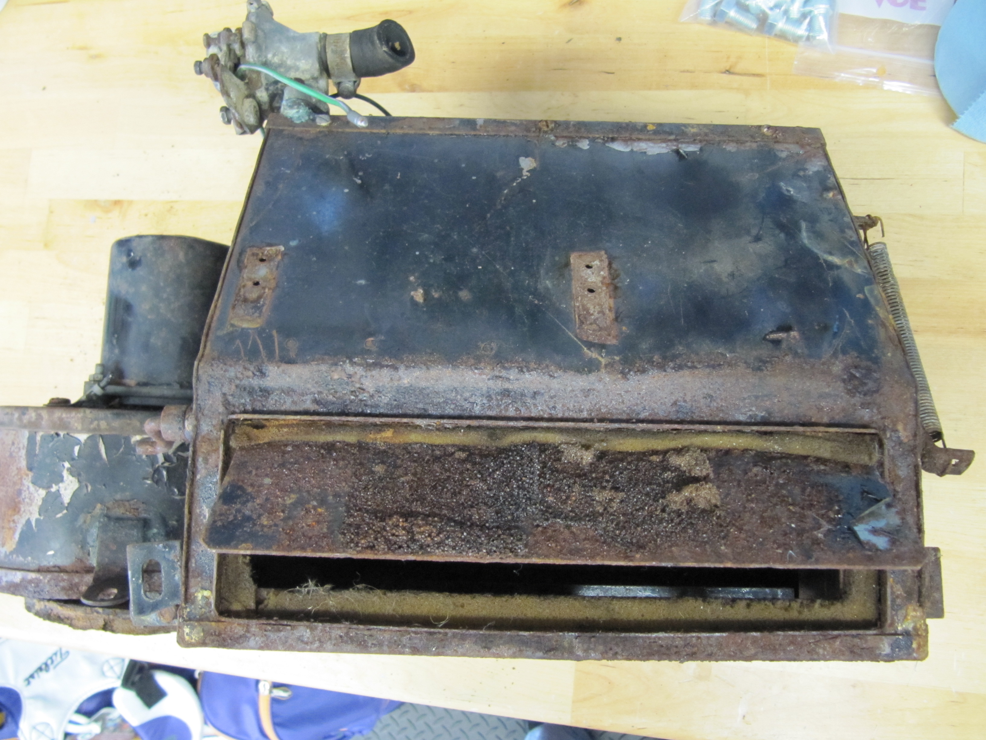
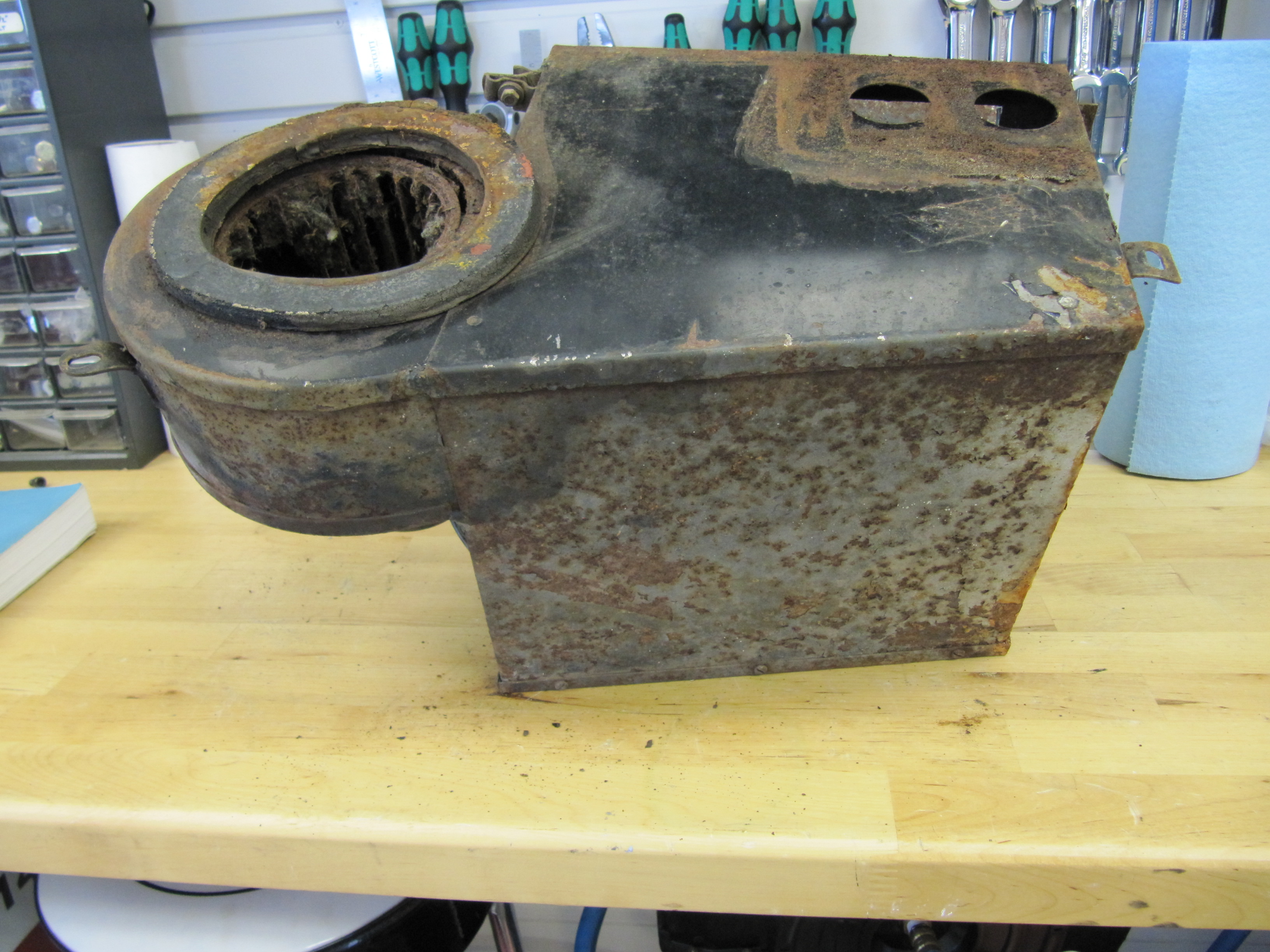
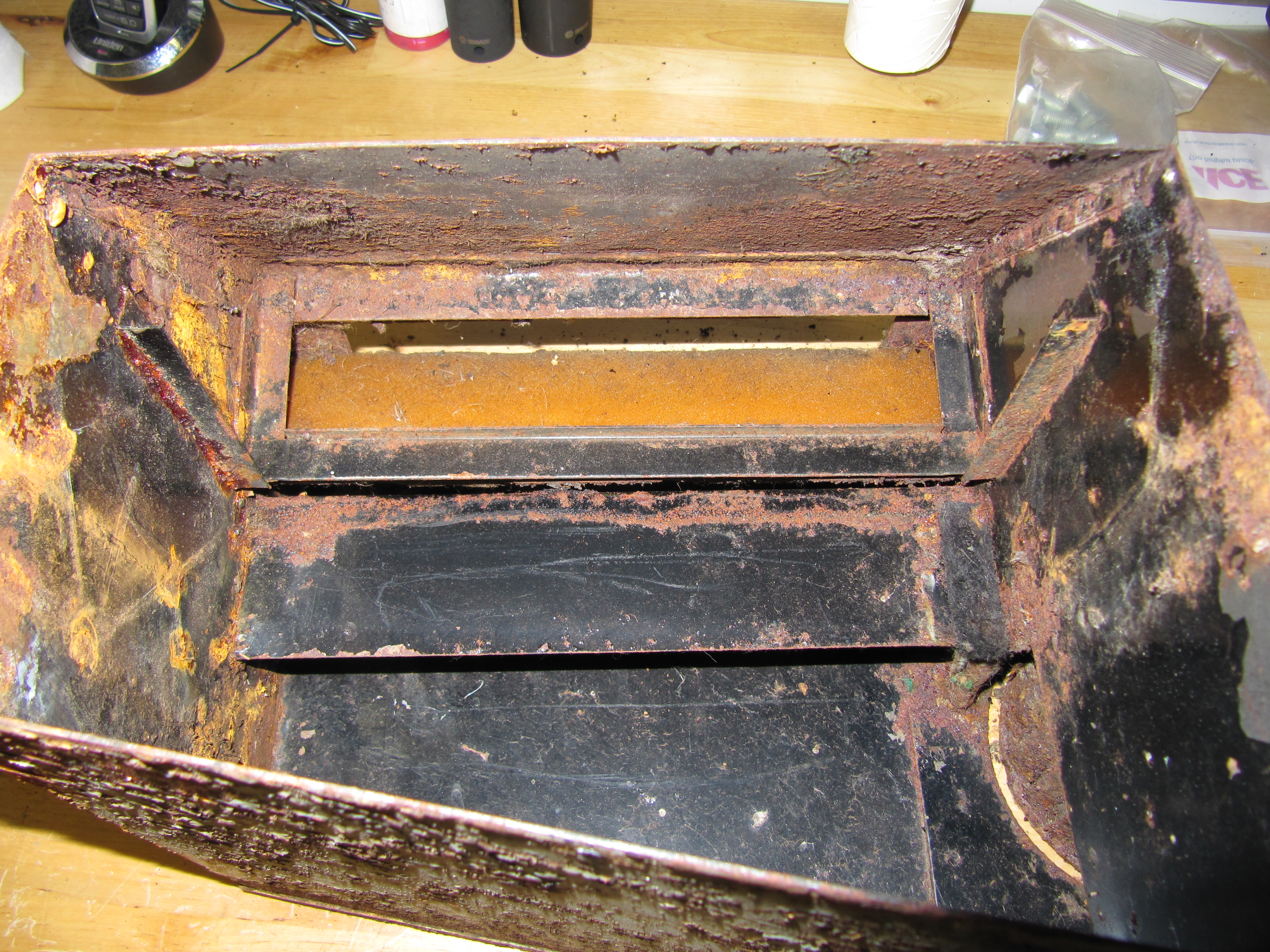
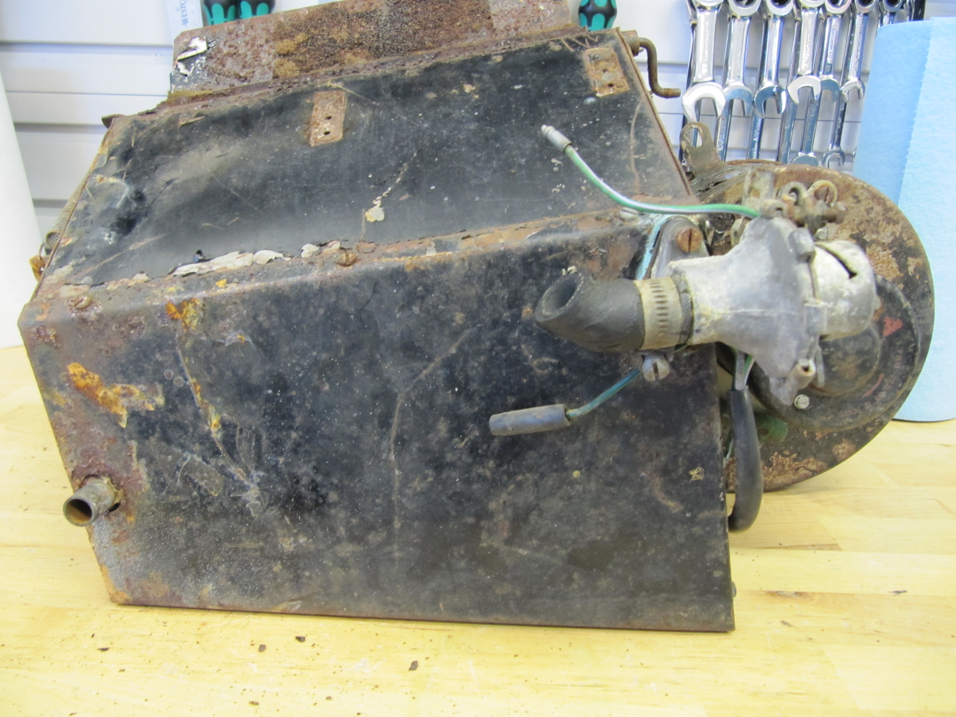
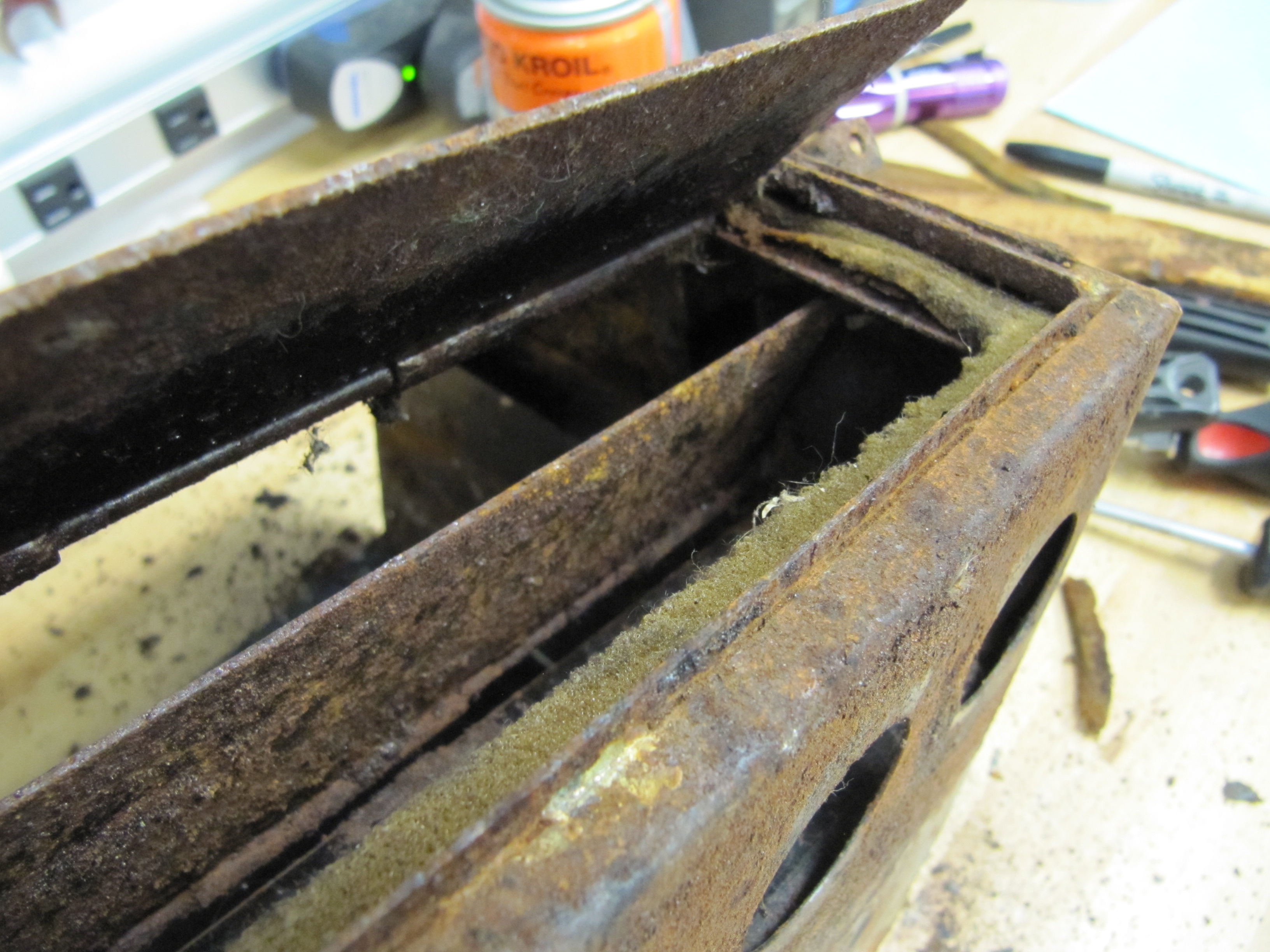
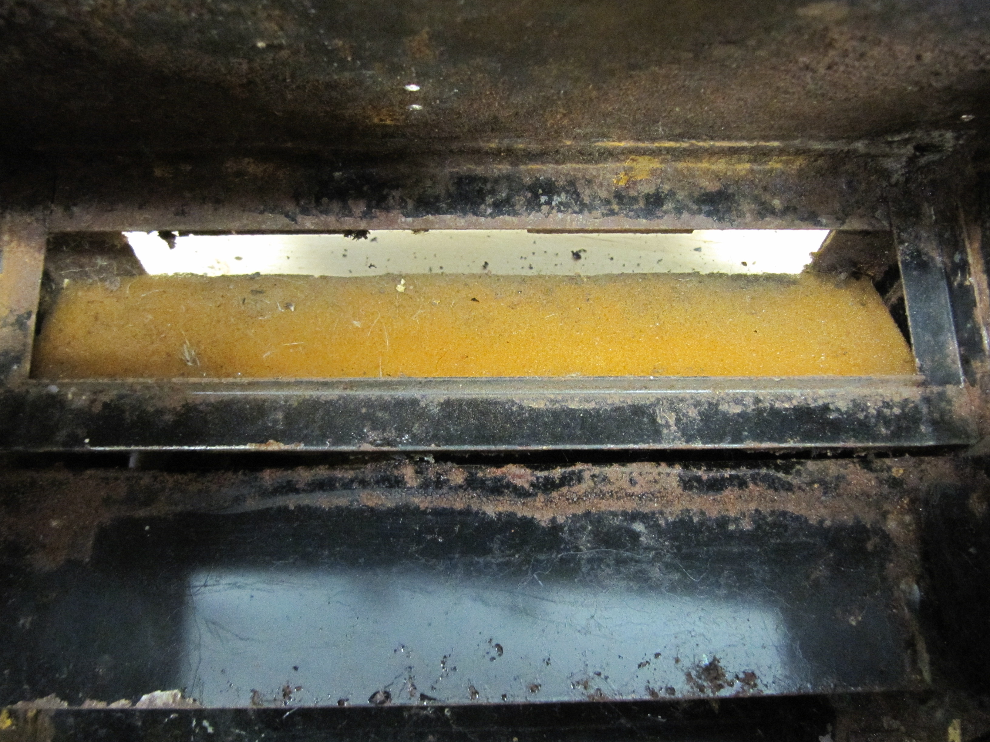
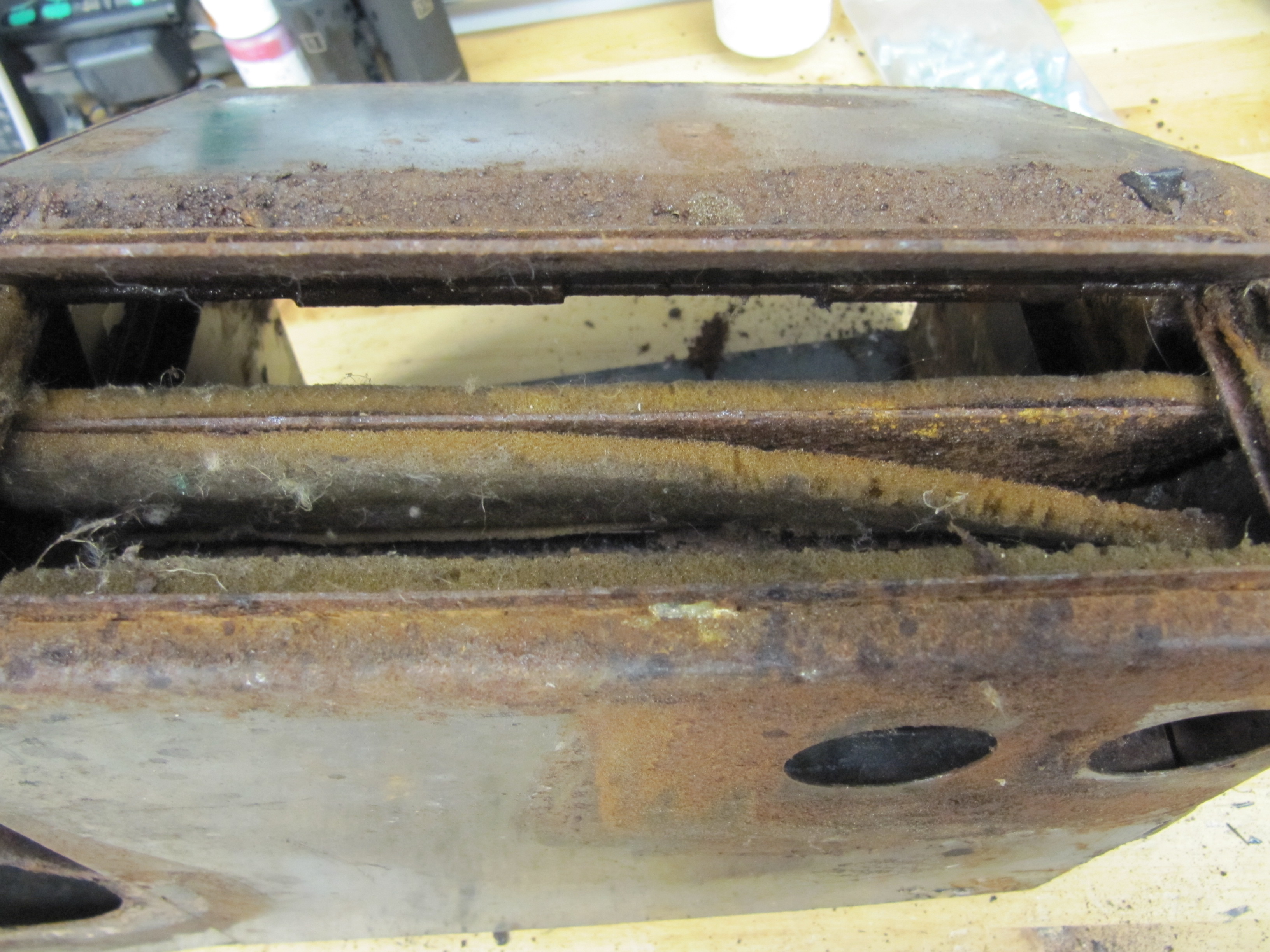
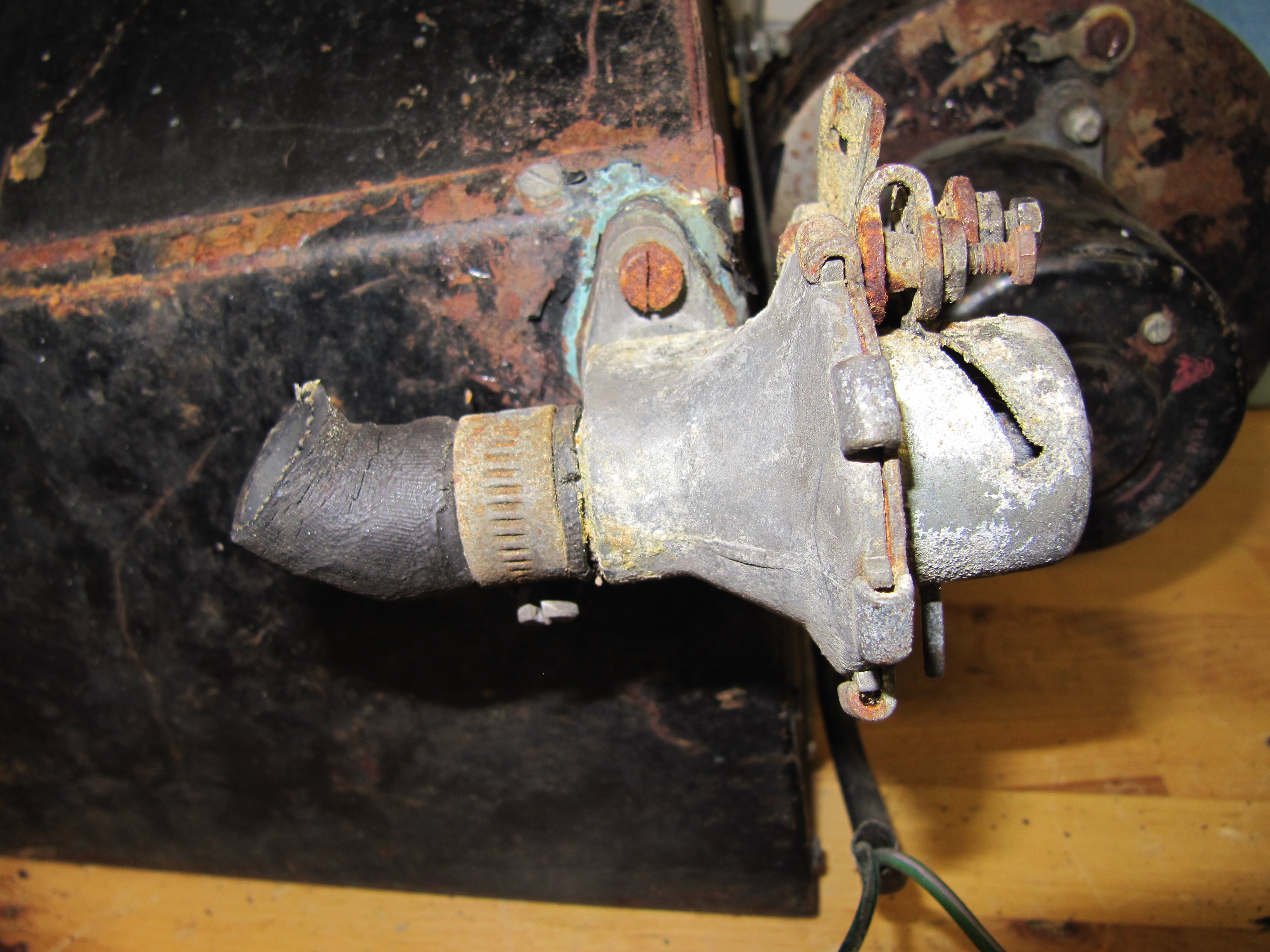
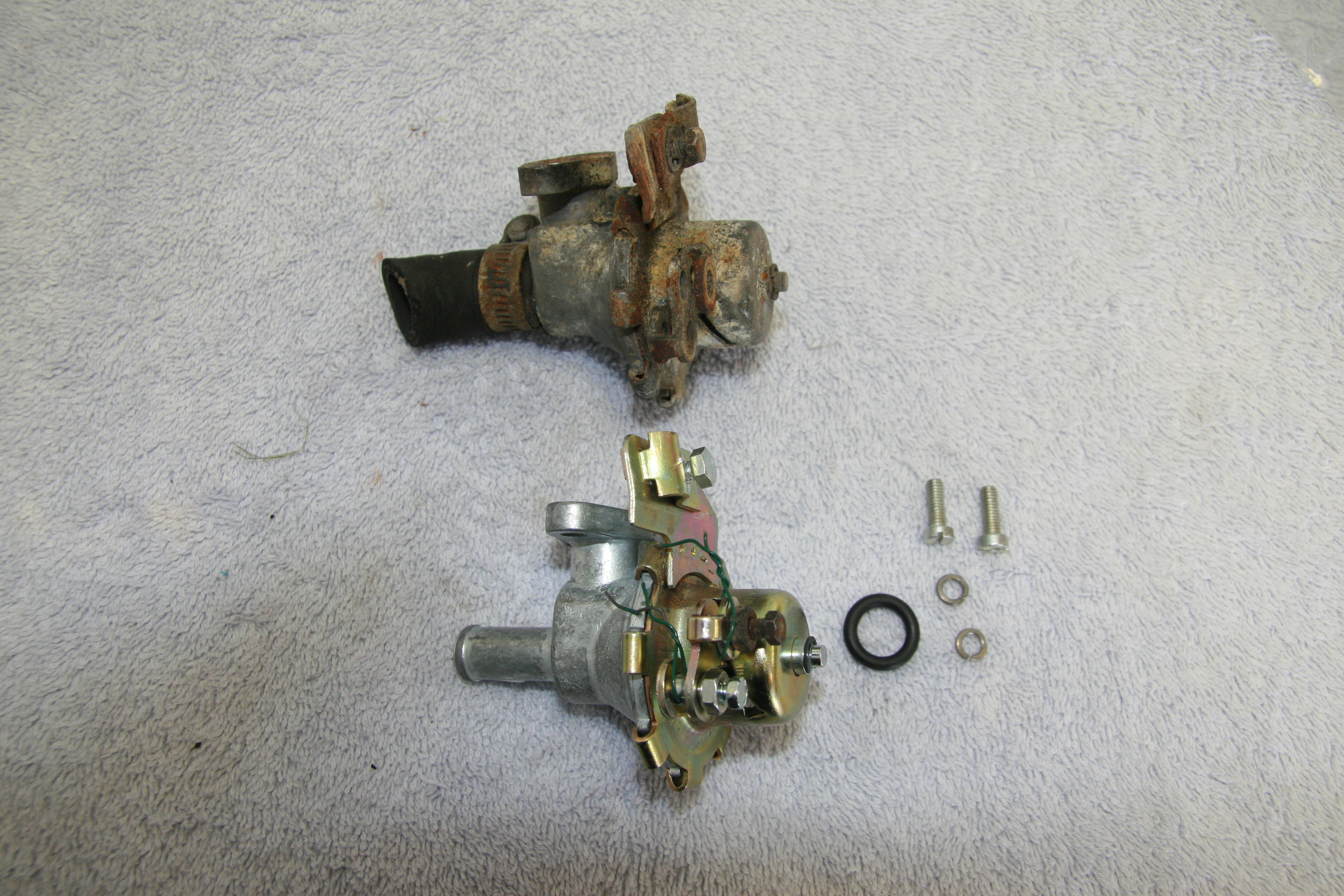
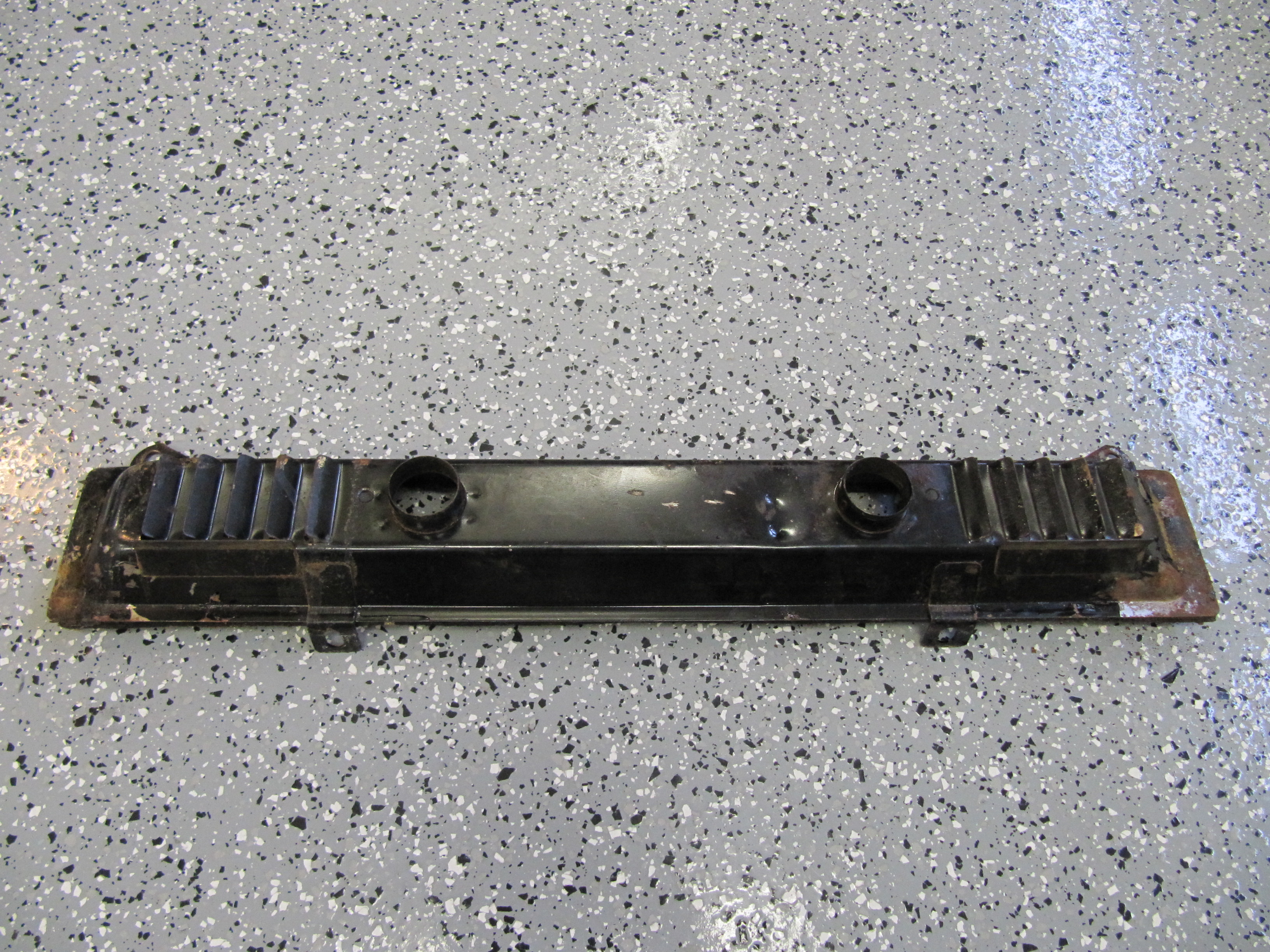
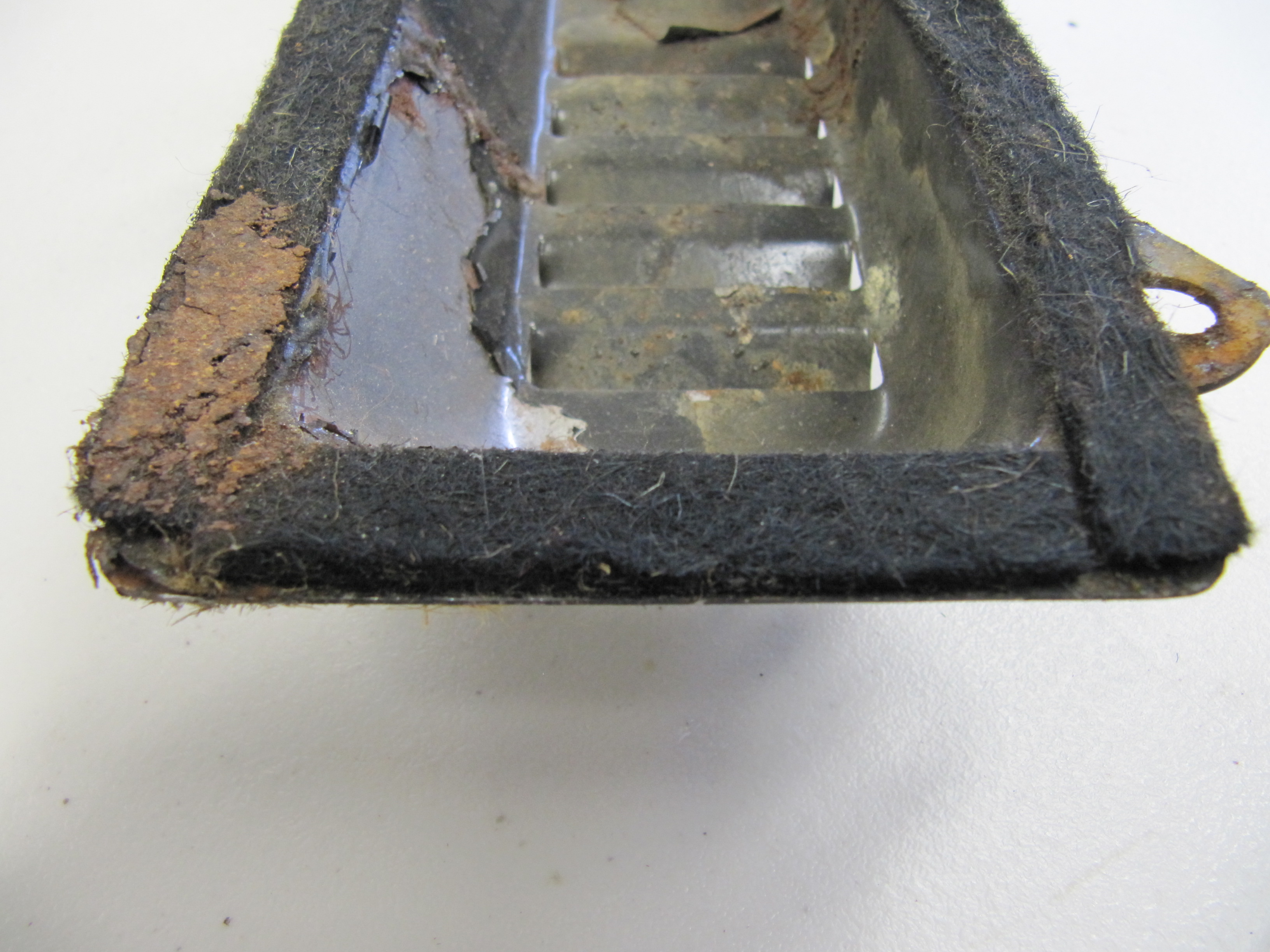
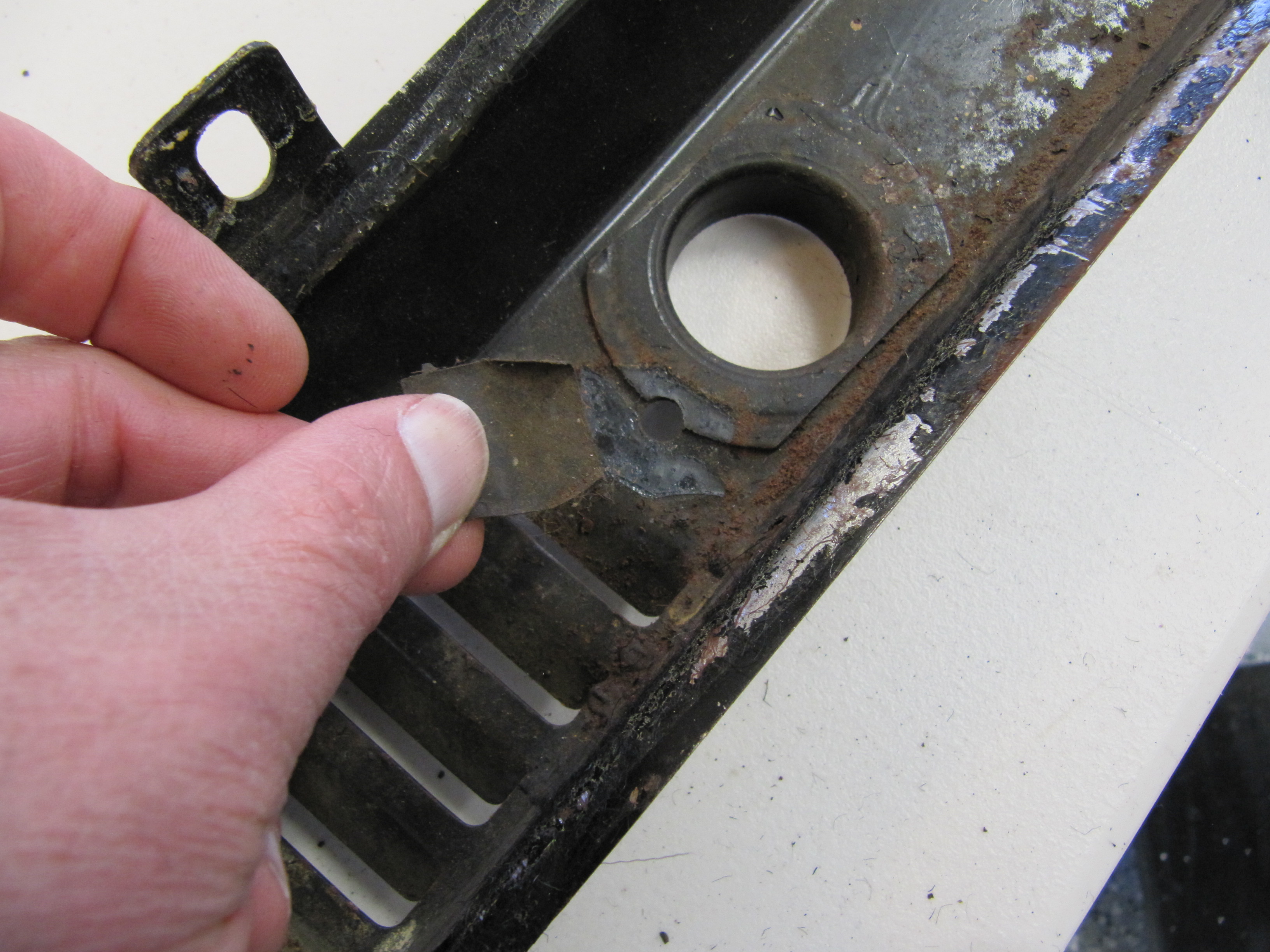
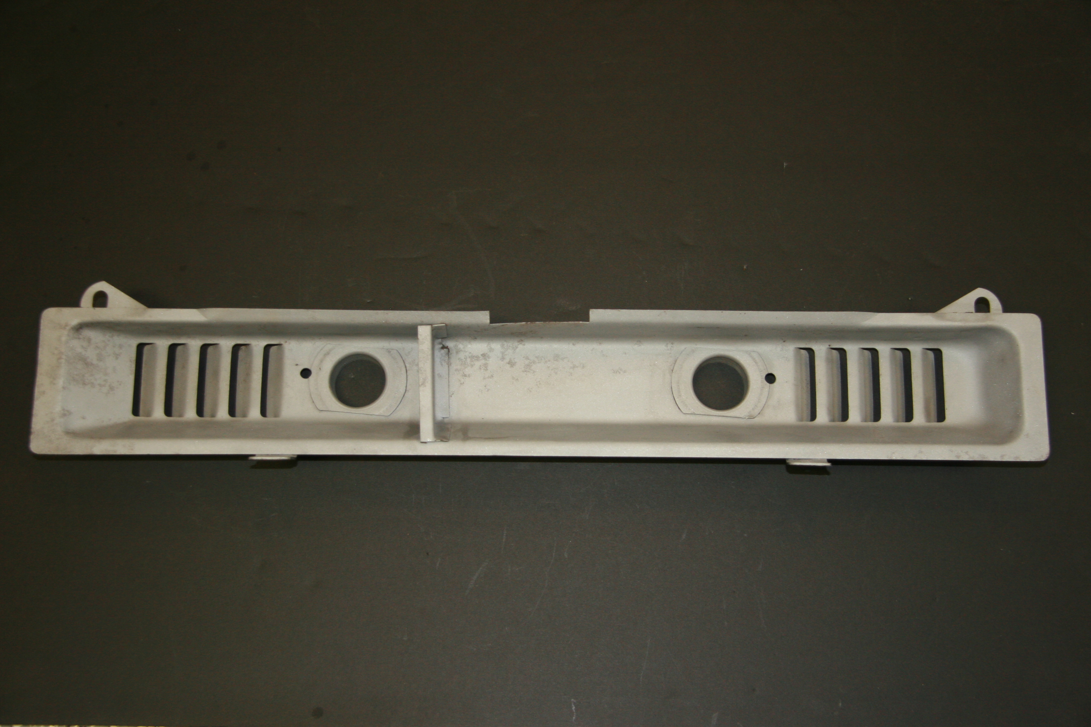
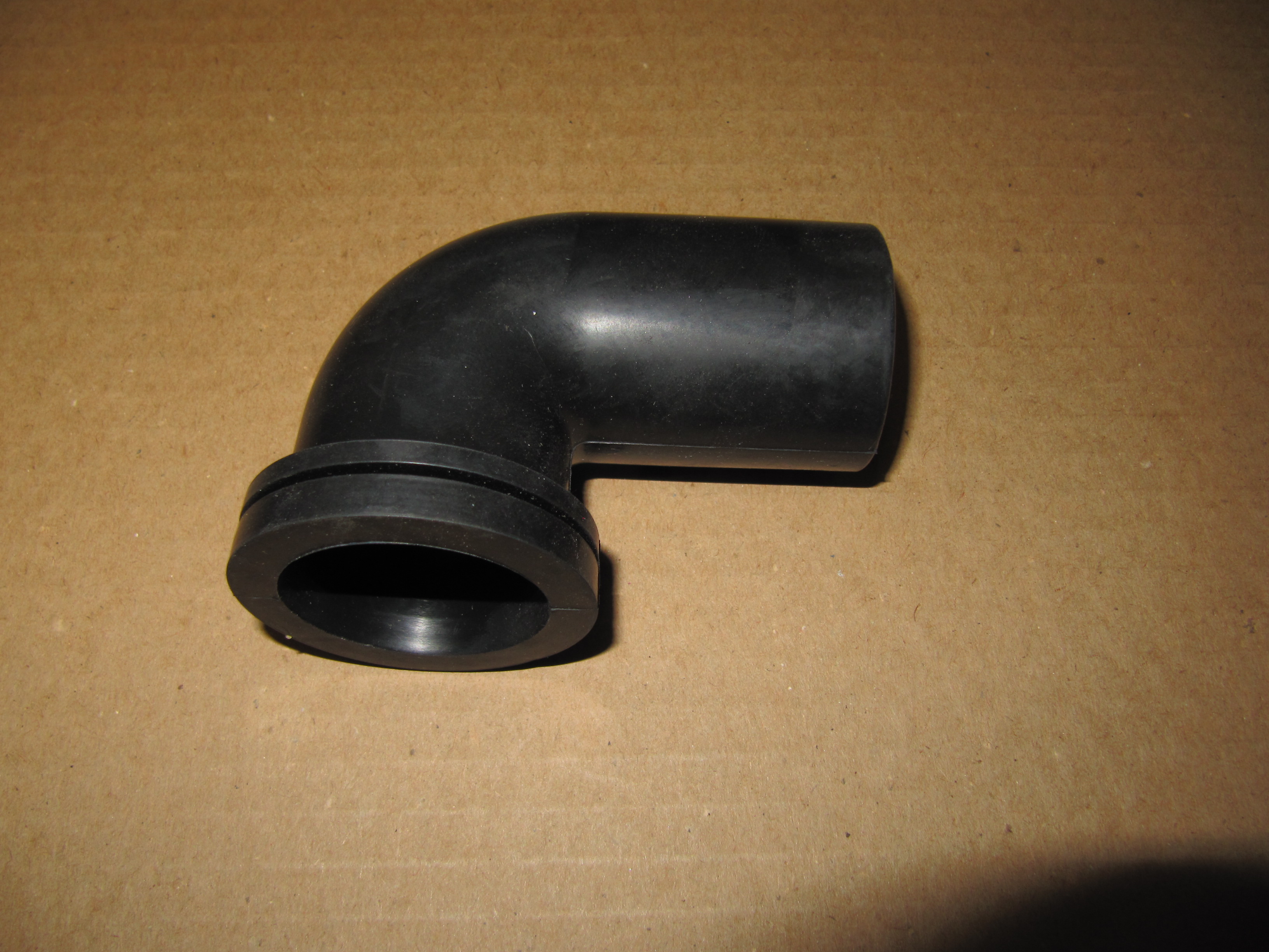
- Air Cleaner for Brake Vacuum Servo
I did clean up and paint the rusted air cleaner.

Air Cleaner for Servo
I purchased a new Hose from the Brake Vacuum Servo to the air cleaner and cleaned up and painted the Supporting Clip that used a hex head #10 – 32 x 1/2″ bolt, shakeproof washer and hex nut to tighten the clamp on the hose and air cleaner.

Air Cleaner, Hose, Support Clip and Clip for Vacuum Servo
Brake Servo Vacuum
I purchased vacuum hose from XKs Unlimited and was very pleased with the fabric covering on the hose that looks very original. I also cleaned and cad plated the original 9/16″ clamps.
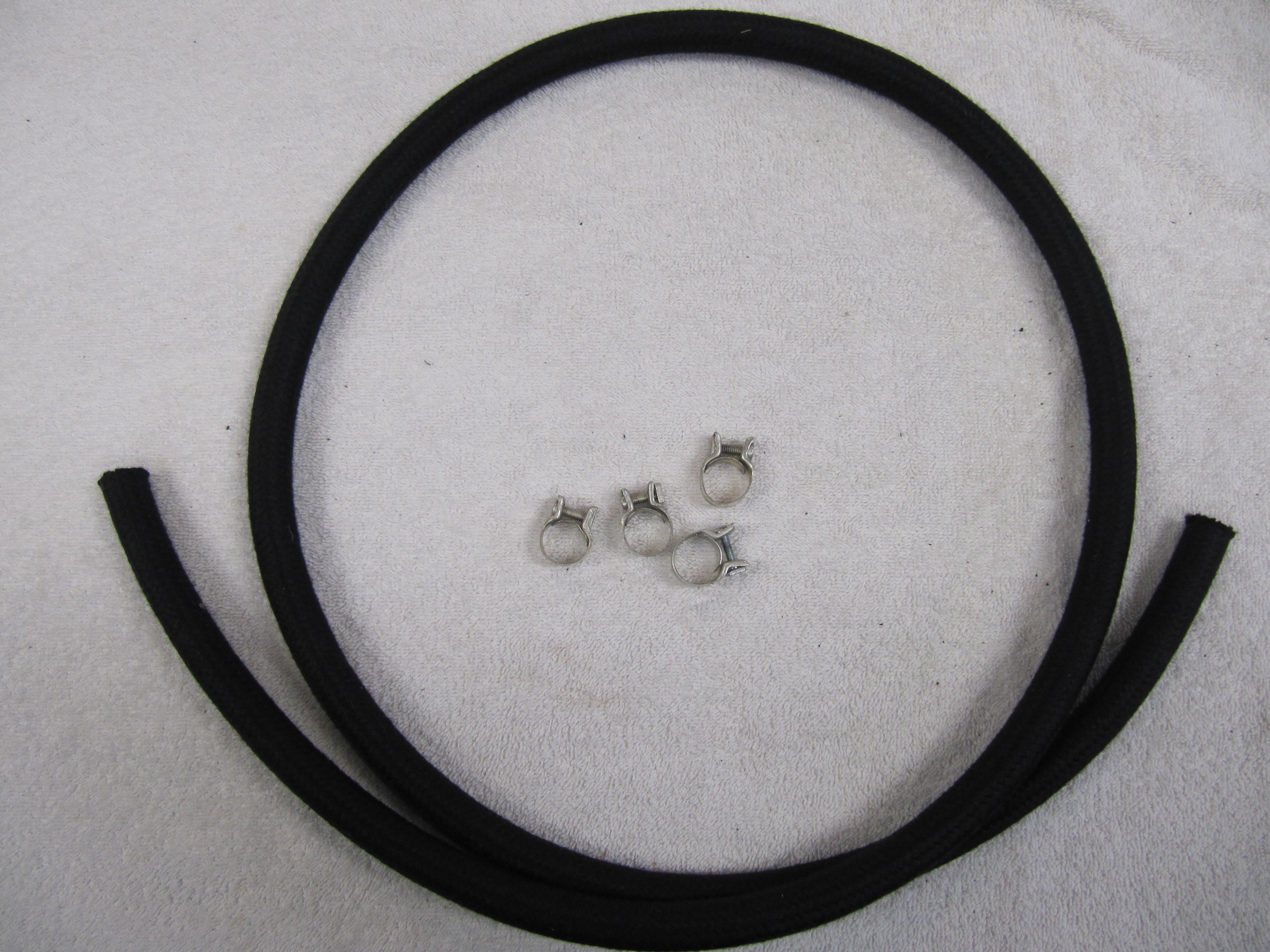
Vacuum Hose and Clamps
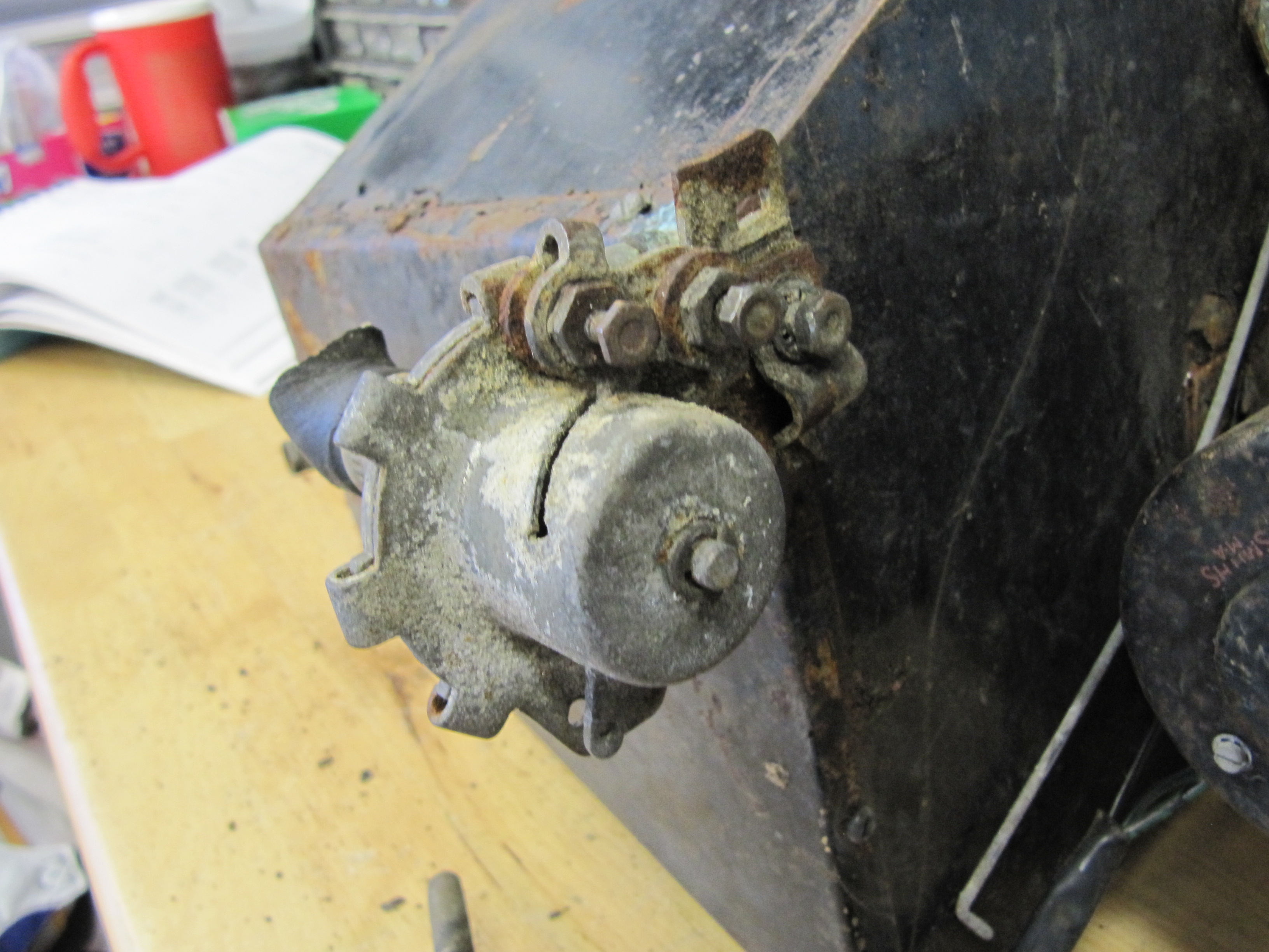
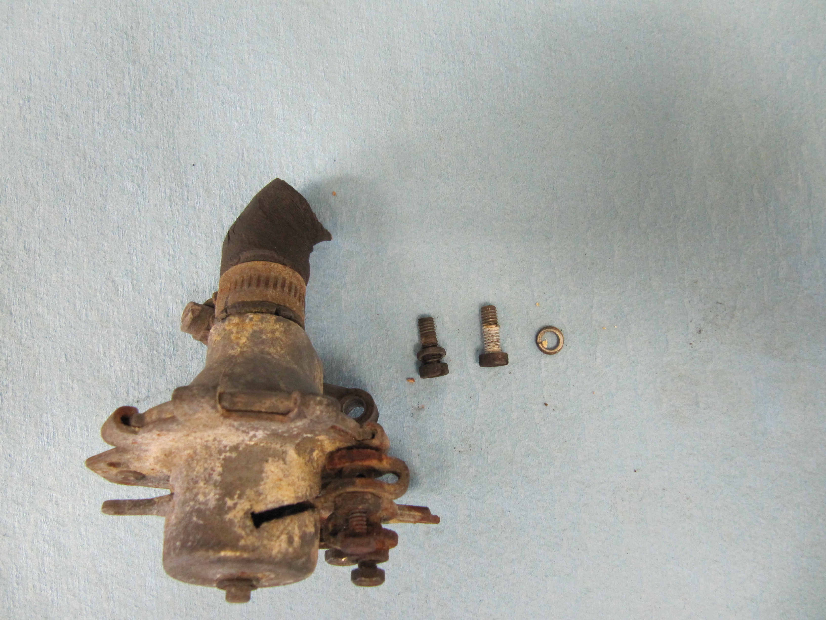
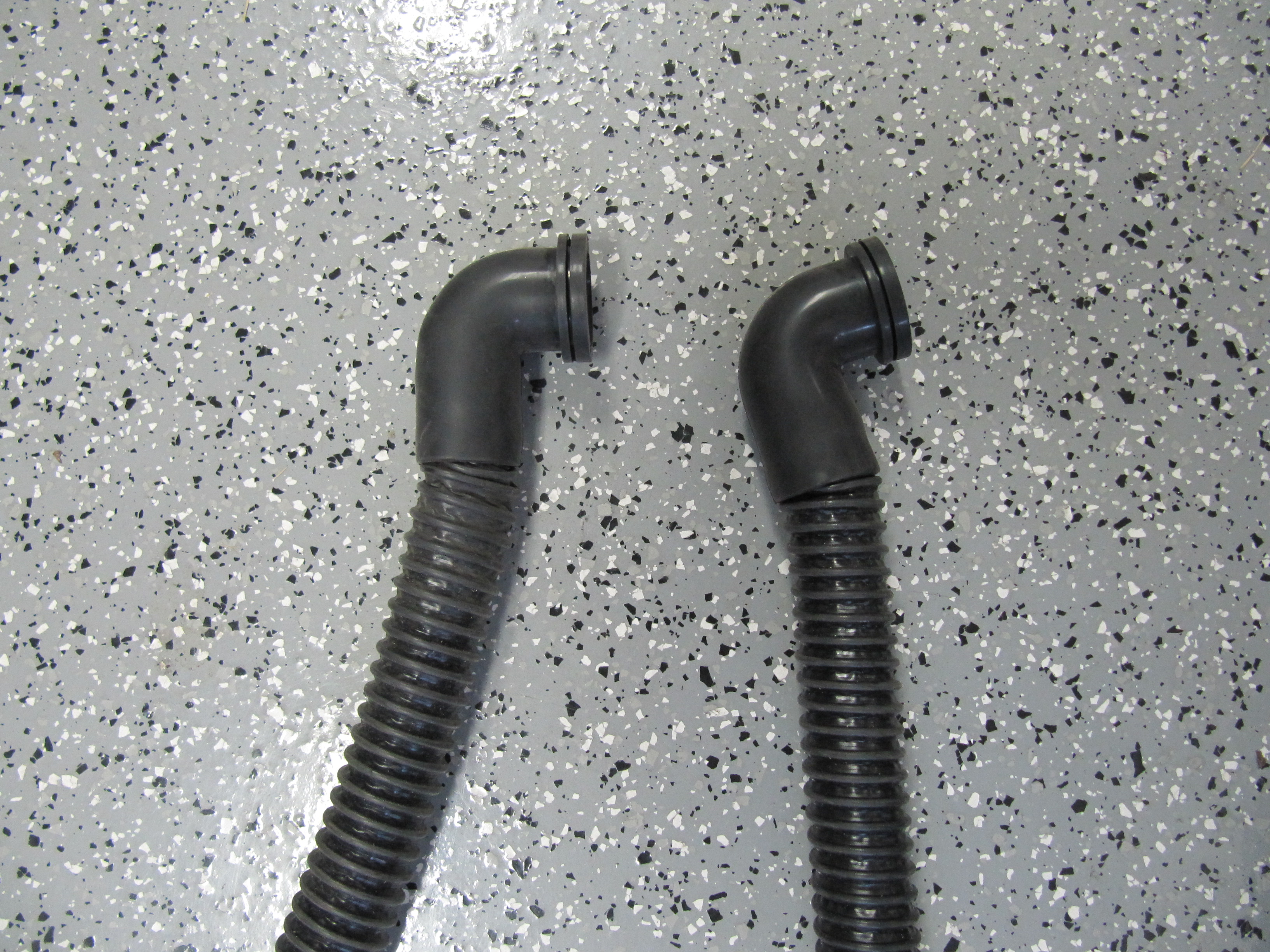
Brake Servo Vacuum Pipe
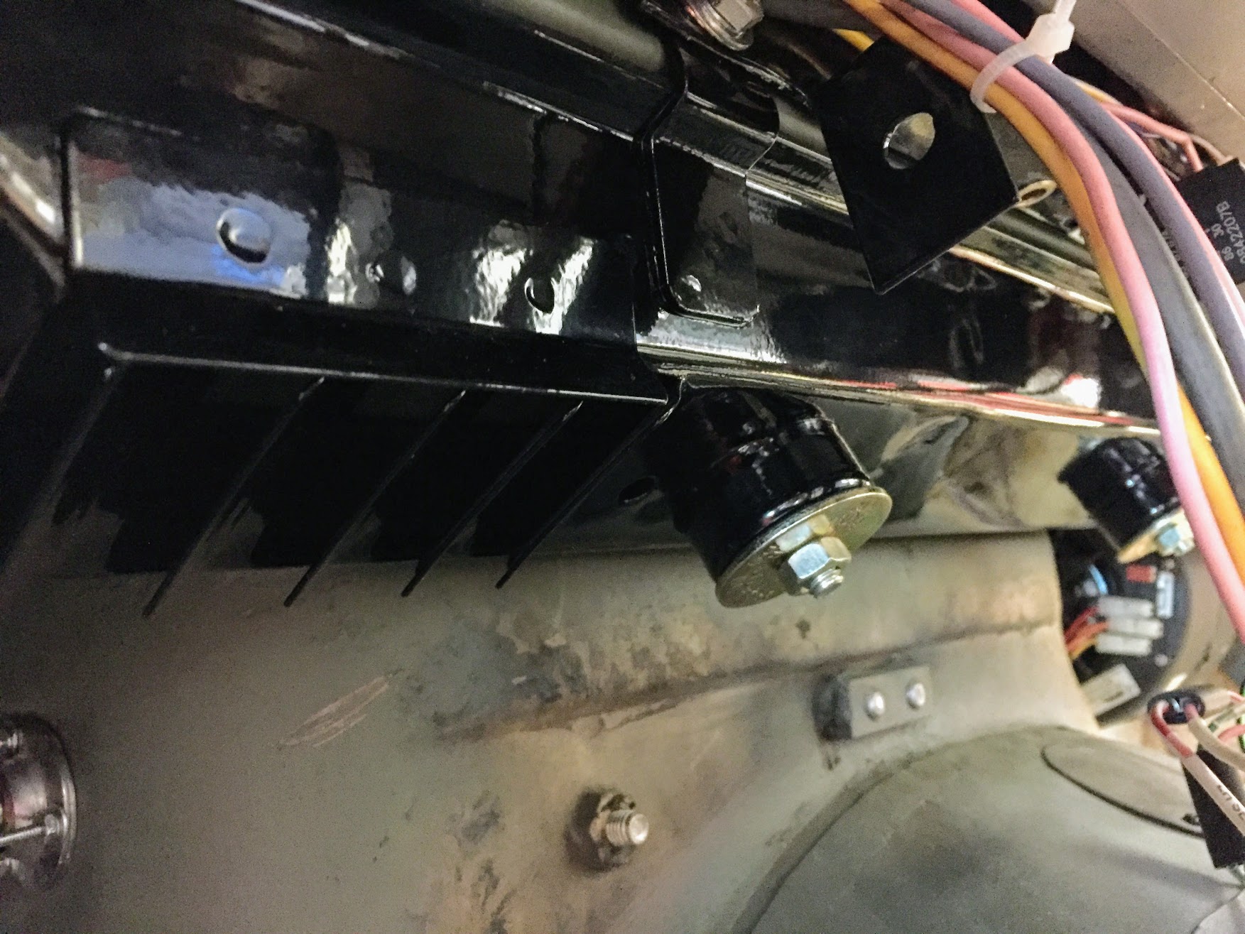
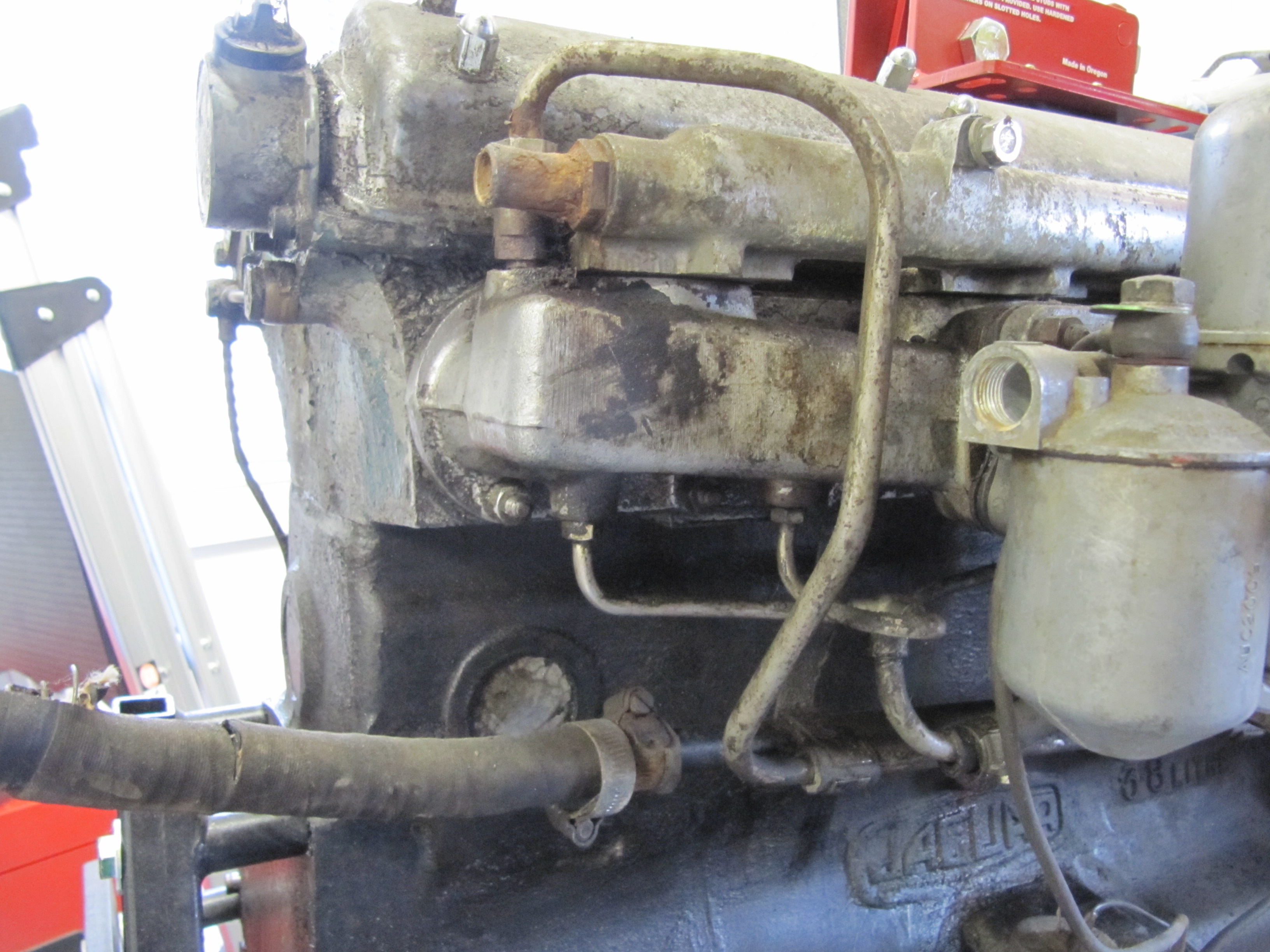
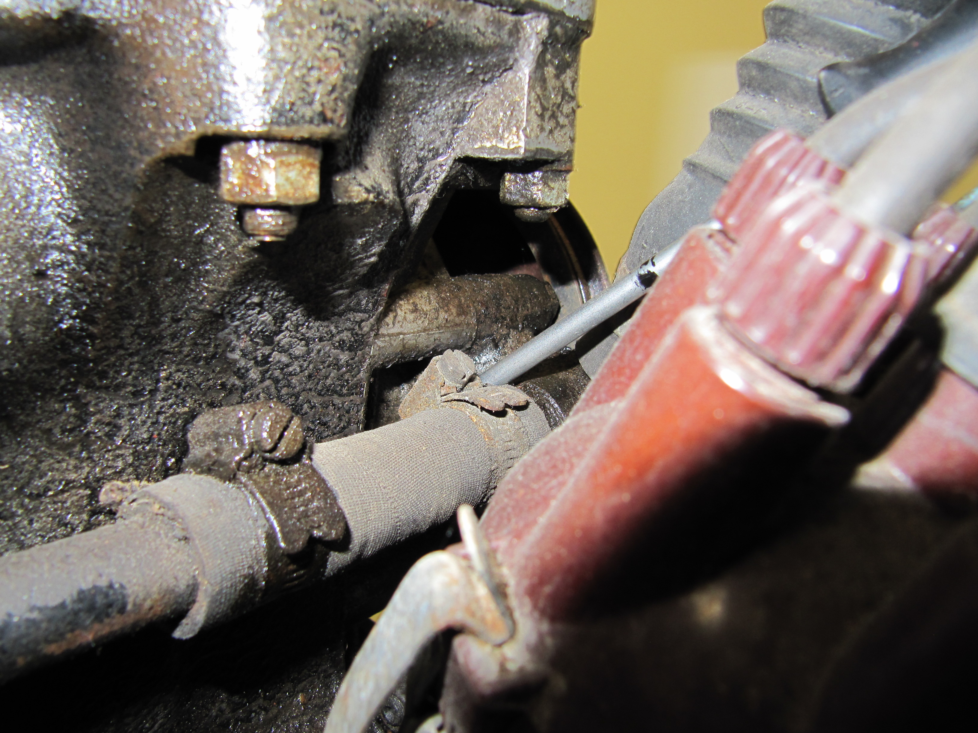
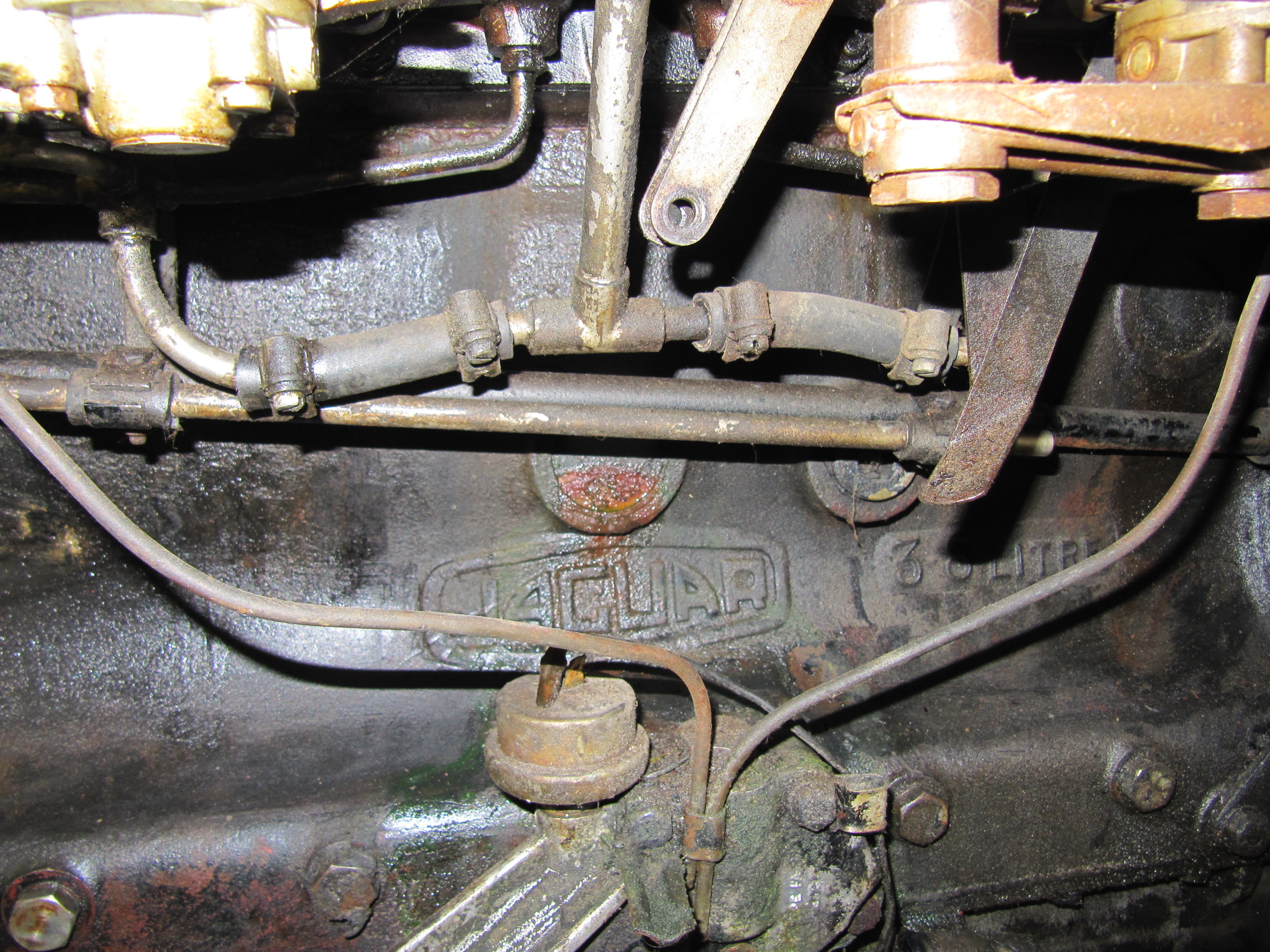
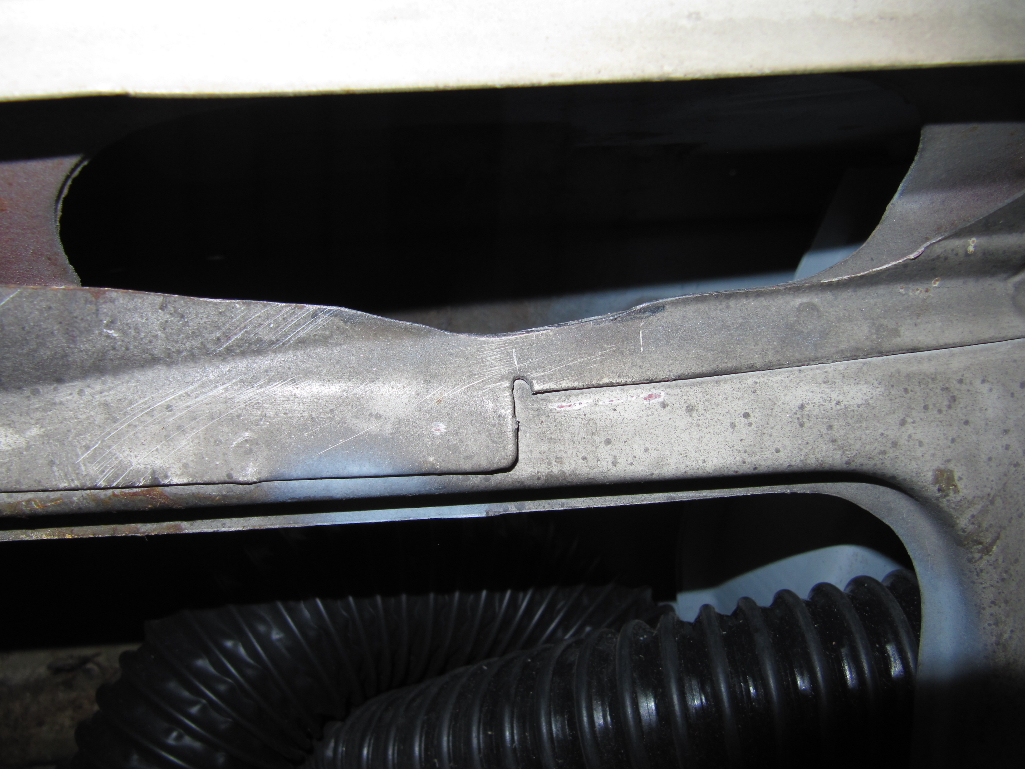
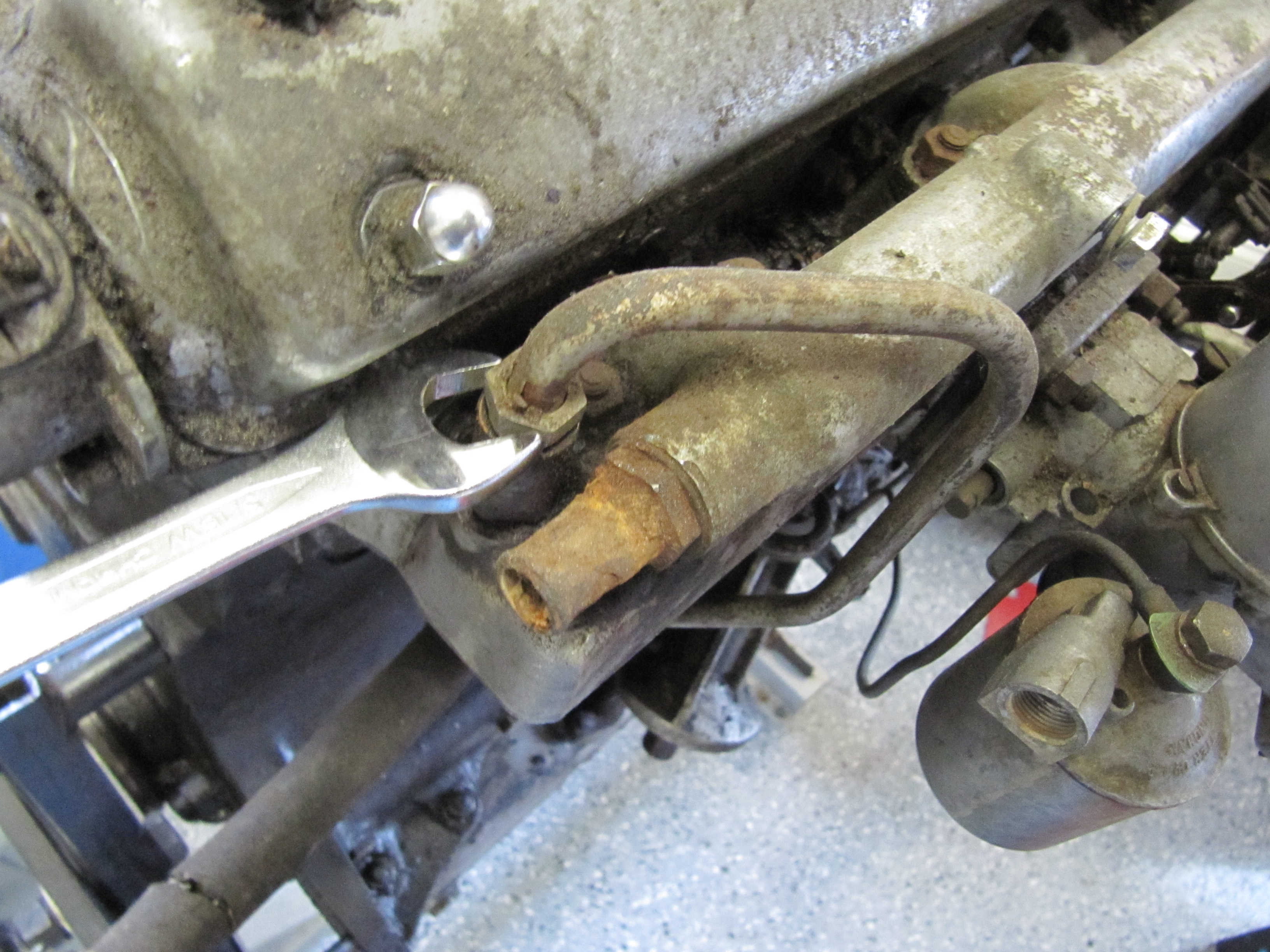
The Pipe is connected to the top rear of the inlet manifold and routes to the servo parallel to the cylinder block. The pipe is paired with the Front Return Pipe for the Heater and secured to the side of the block with the same brackets (see https://valvechatter.com/?p=4681). I loosened the flaired pipe fitting nut and removed the pipe.

Vacuum Pipe Mounted to Inlet Manifold
Servo Vacuum Pipe

Servo Vacuum Pipe
Rear View
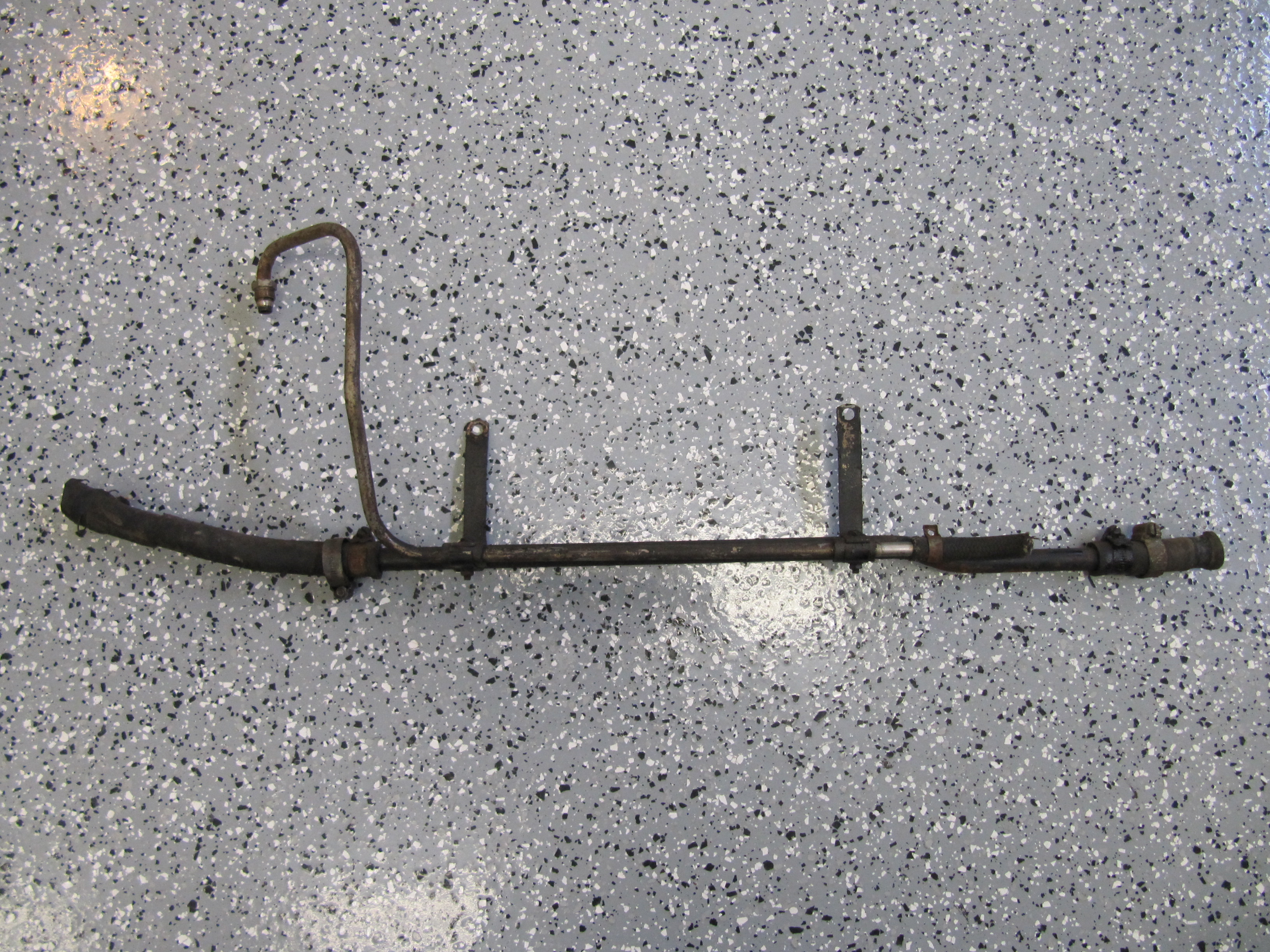
This is the pipe after cleaning and zinc plating.
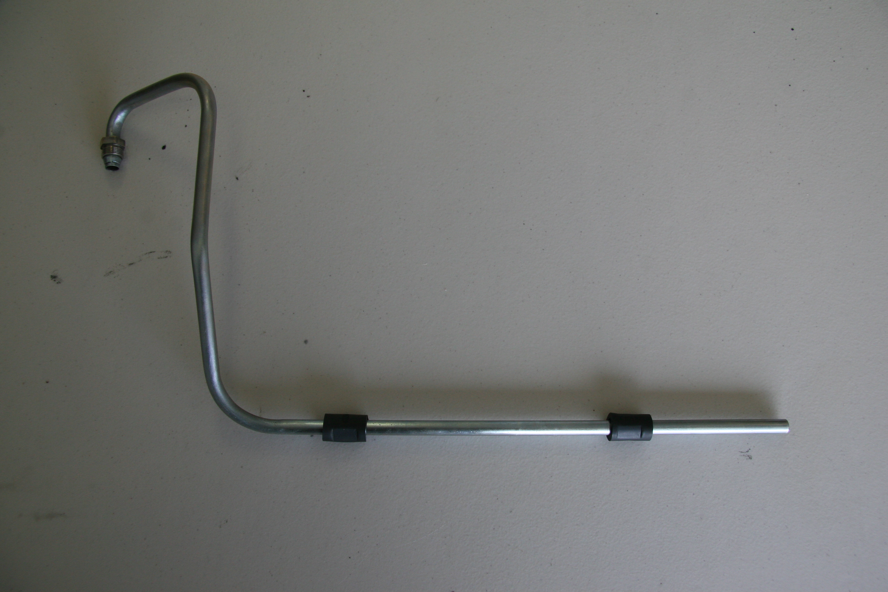
Brake Servo Vacuum Pipe Re-zinced
Hydraulic Lines
Calipers
The two front caliper hoses were replaced with Goodridge stainless steel braided hoses sourced from Coopercraft in England. These hoses use different size fasteners than the original rubber hose.

Goodridge Stainless Front Caliper Brake Hose
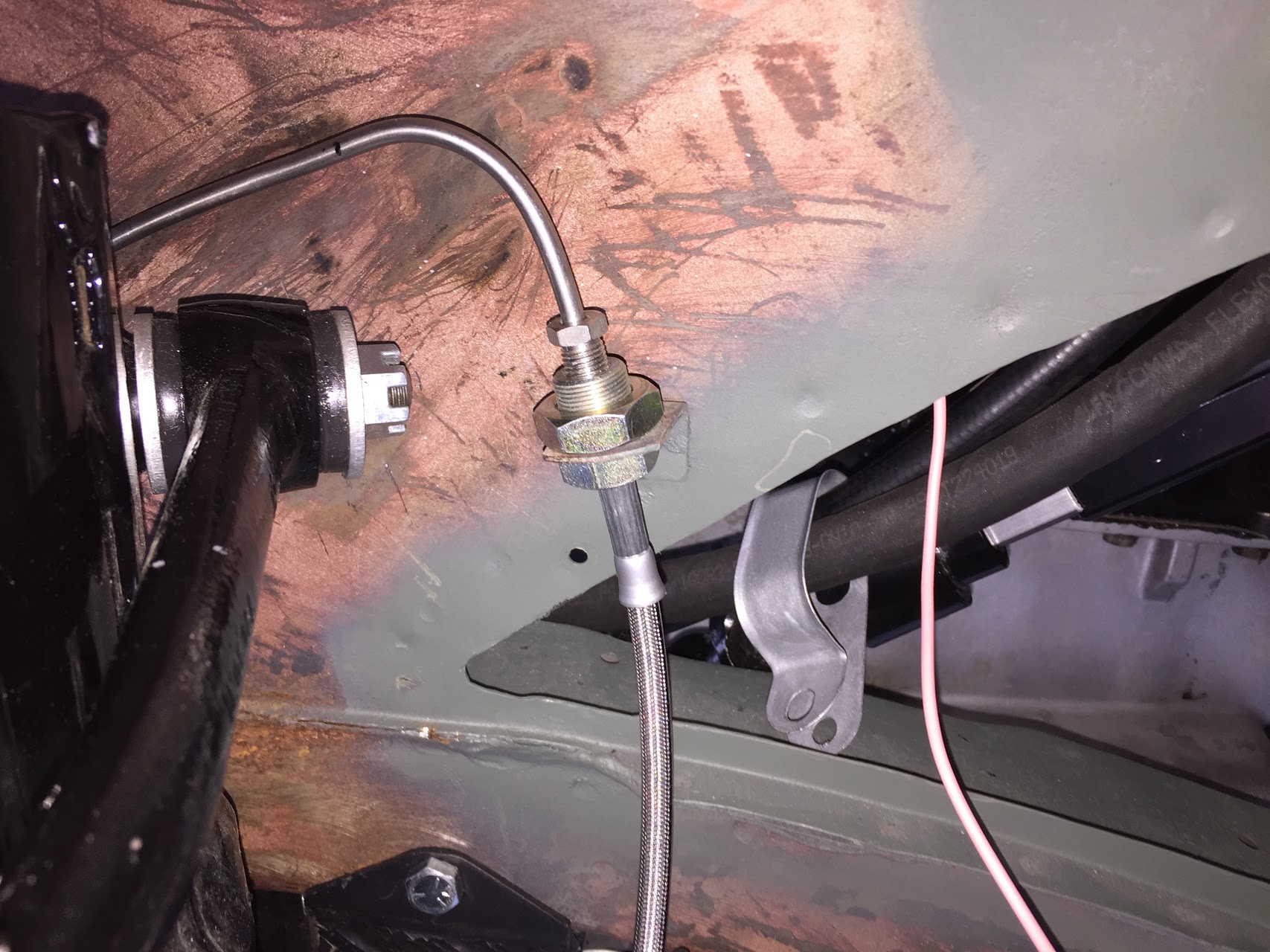
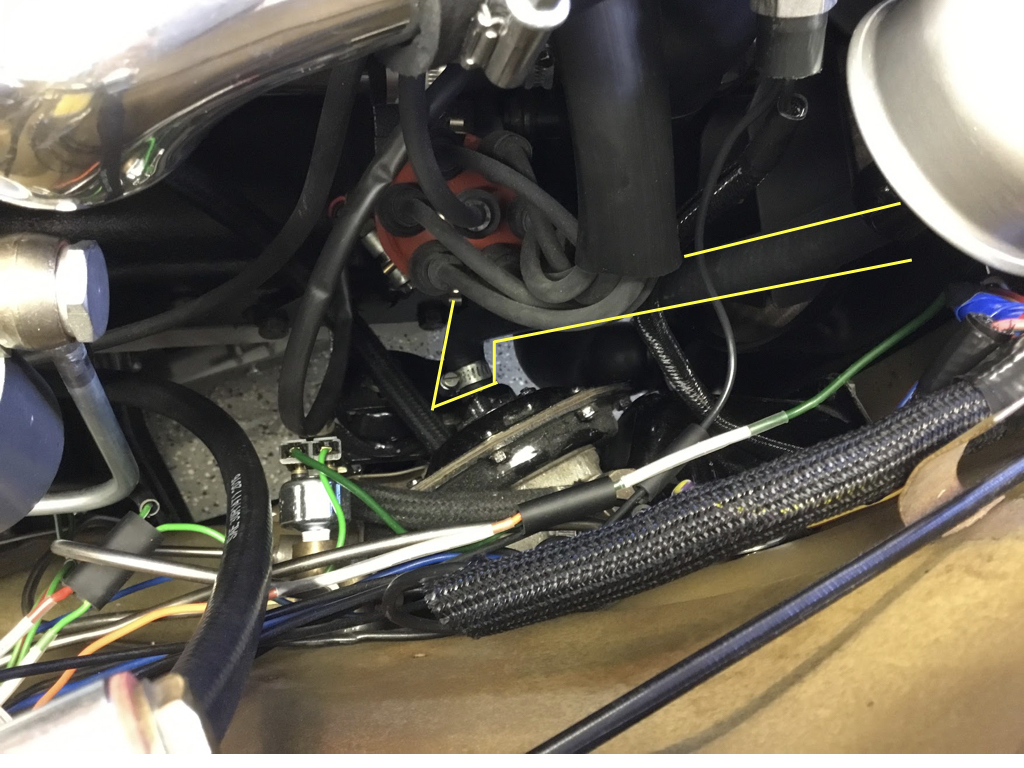
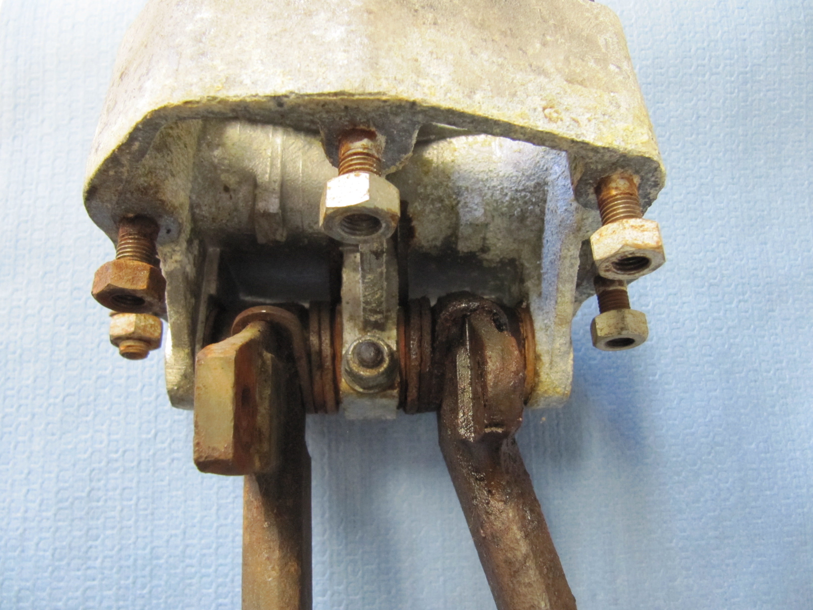
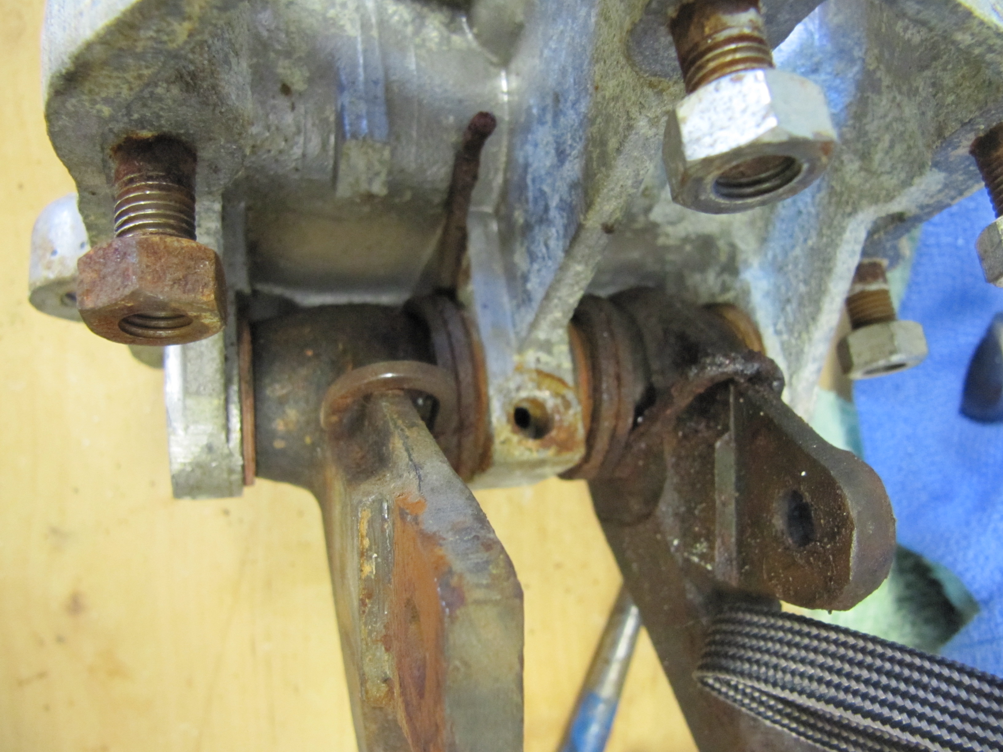
LH Front brake hydraulic line junction to caliper
After examining the image above, a fellow MK2 owner, Bruce Murray, pointed out to me that the hard brake line fitting was not threading very far into the flexible stainless steel hose emanating from the caliper and certainly not as far as one can observe with the original Girling hoses/fittings. Upon closer examination I concurred with his assessment that this is not an ideal situation. I am not saying that this is unsafe or that the arrangement won’t work satisfactorily; however, in my view one shouldn’t be taking any chances with braking systems. I like the claimed improved performance of stainless steel brake hoses and I like their looks, but I am going to switch to standard rubber hoses. An alternative would be to cut the hard line and install a fitting appropriate to the stainless steel flex line, but I will just go with the rubber hoses.
I will post more comparative information when my rubber hoses arrive.
Rear Axle
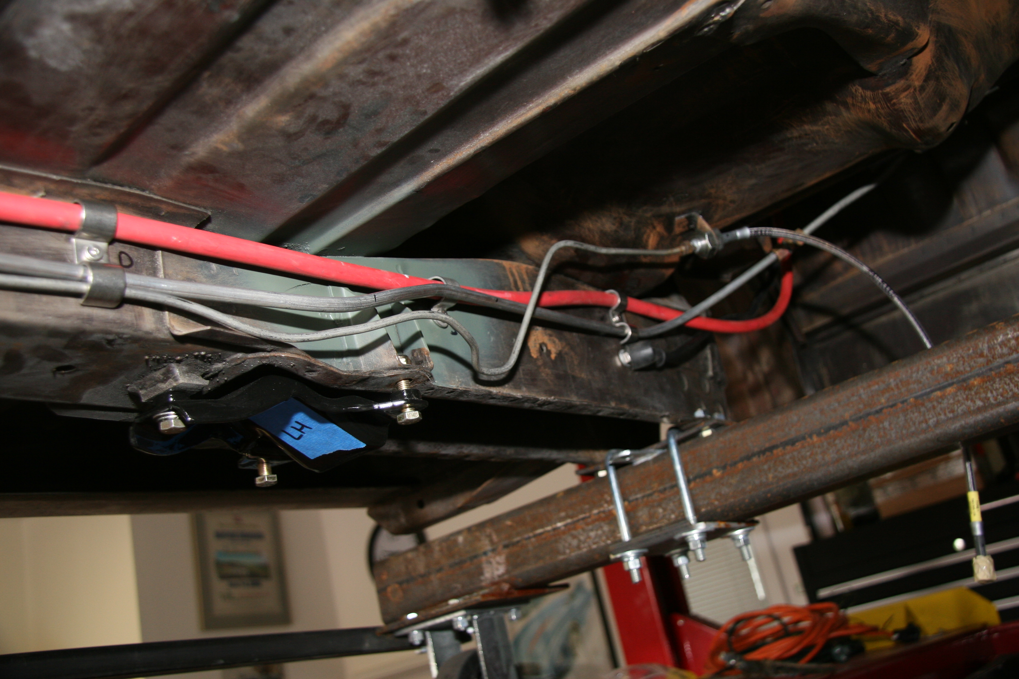
The hydraulic pipes connecting the rear brakes travel along the rear axle and are held in place by three clamps with 1/4″ – 28 x 1″ cheesehead screws and hex nuts and shakeproof washers. A flexible hose is used to connect the long hydraulic pipe that runs the length of the right hand side of the frame to the axle piping. The original hose was provided by Lucas and was rubber, and I had planned to use a Goodridge stainless flexible hose replacement that was sourced from Coopercraft in England. However, for the reasons stated above regarding the stainless hoses for the calipers, I will revert to the rubber hose upon final installation.
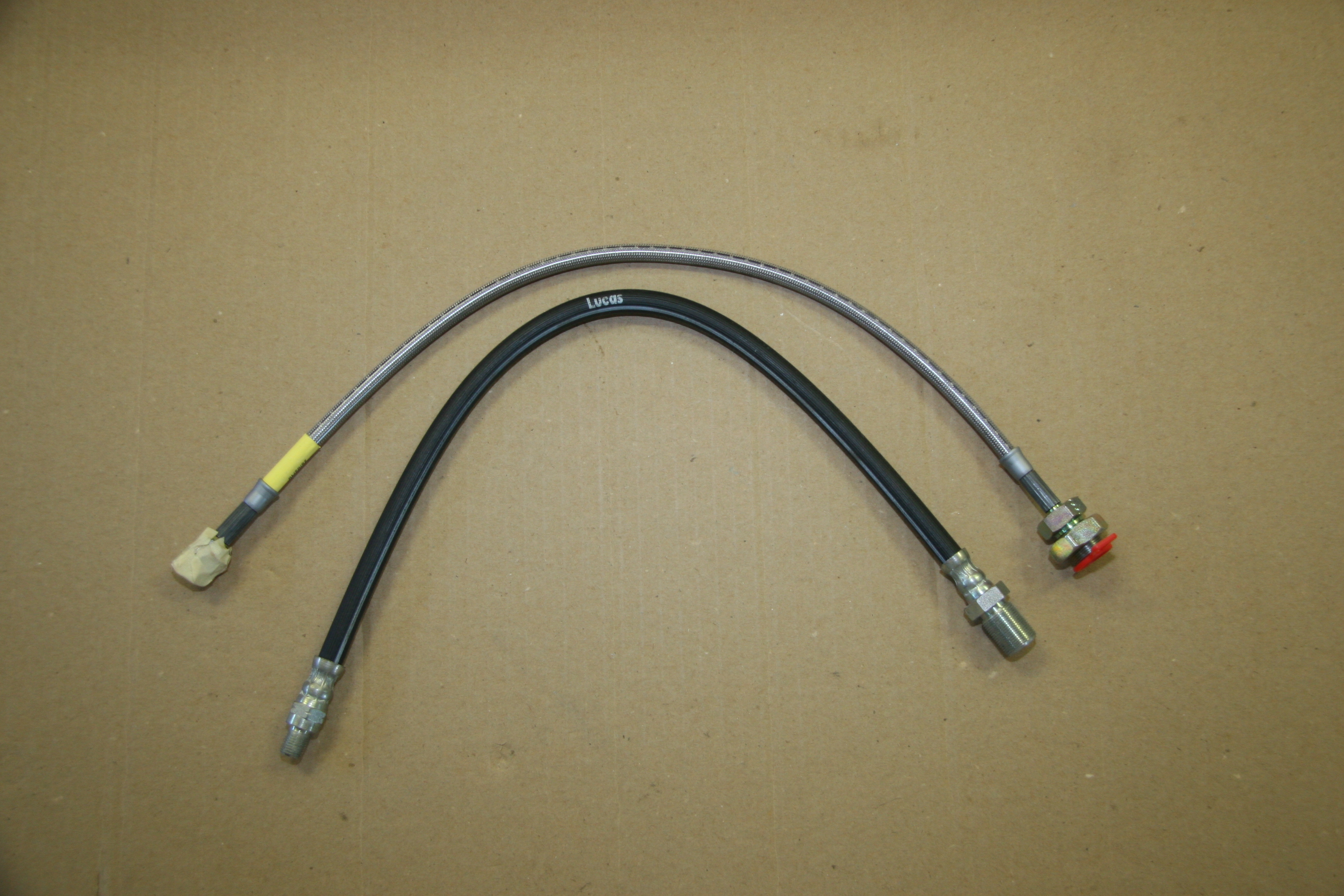
Rear Flexible Brake Hose Lucas Rubber and Goodridge
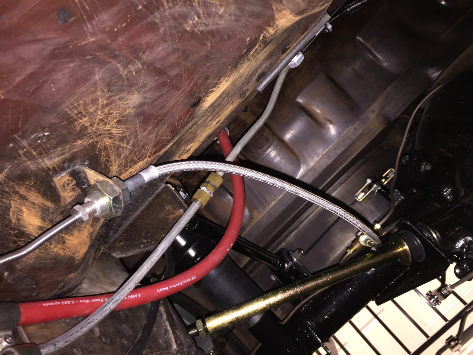
Goodridge Stainless Flexible Hose from Pipe to 3-way Adaptor with Copper Gasket Installed
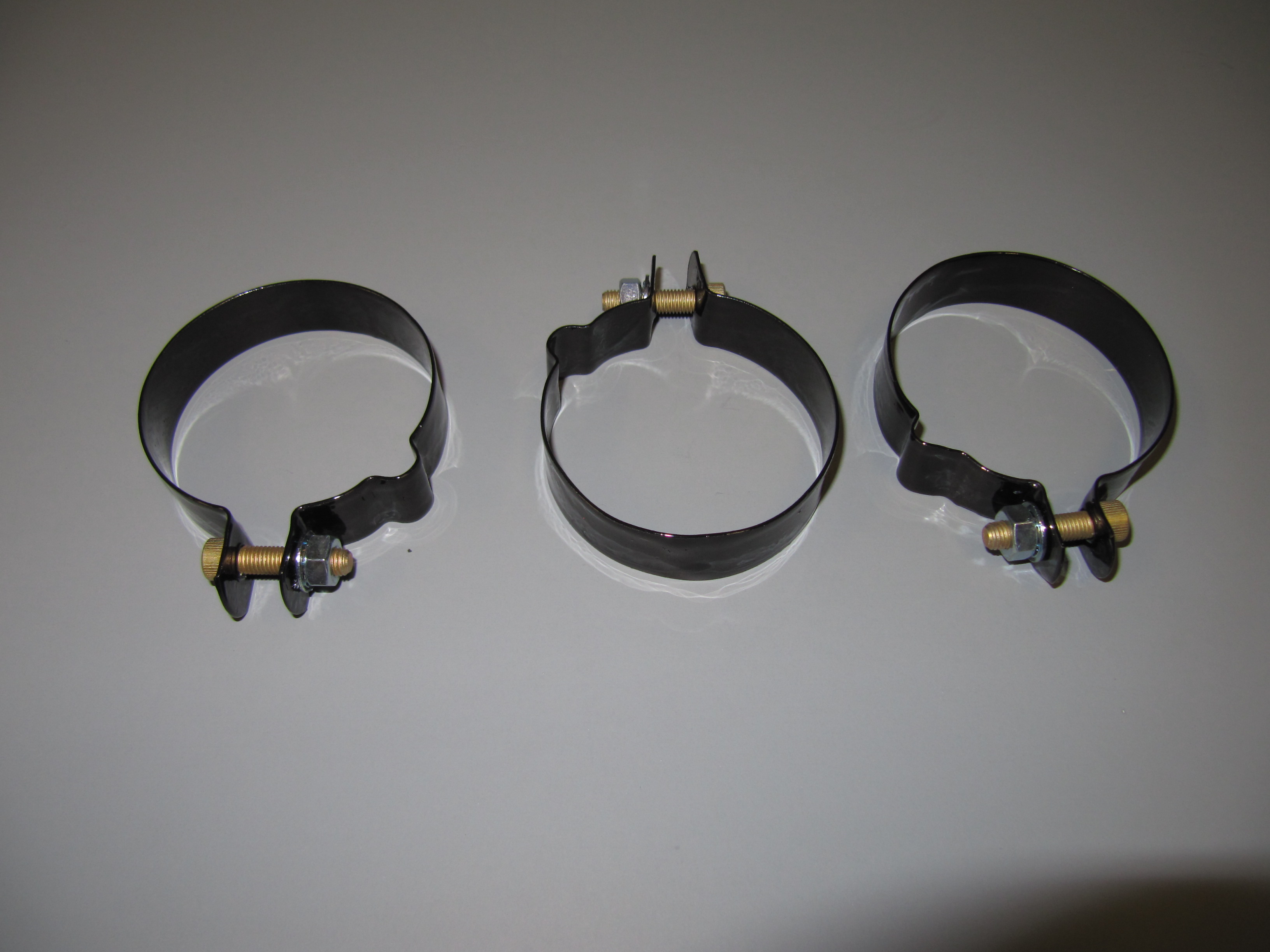
Clips Securing Hydraulic Pipes to Rear Axle
Hydraulic Pipes
I took the more expensive, but much easier way out with the hydraulic pipes and purchased pre-bent stainless steel piping. The fit on several pieces was actually not very close but eventually everything was installed.
Clutch
There are two clutch hard lines. One from the master cylinder to a firewall brace and the other from the firewall to the slave cylinder.
Clutch Pipe from Master Cylinder to firewall
Clutch Pipe from Firewall Mount to the Slave Cylinder
Brakes
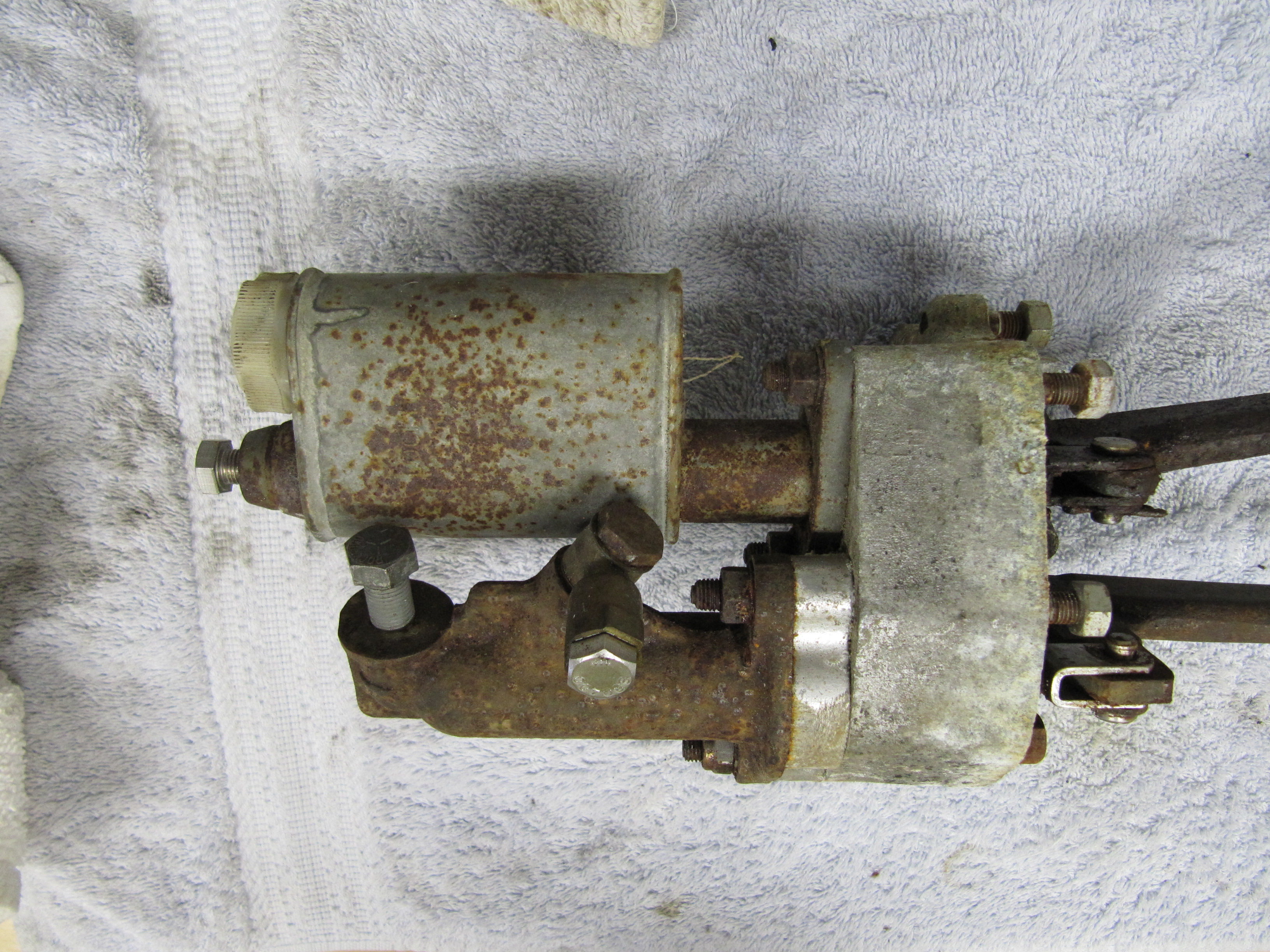
Master Cylinder
Note in the photos above that I have the master cylinder rotated 180 degrees from its position when I removed it from my car. See photo below:
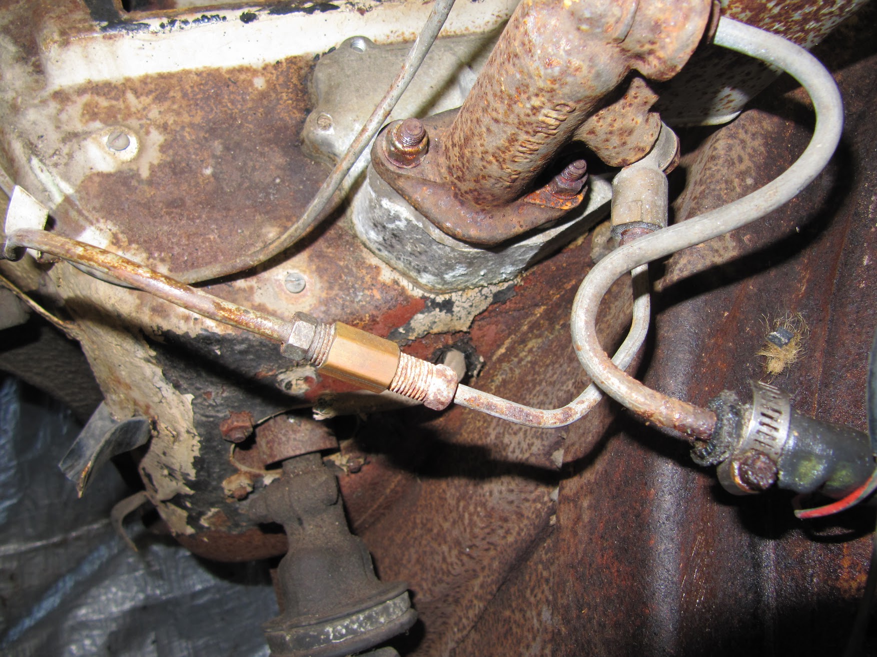
Master Cylinder and Hydraulic Pipe with fitting
The original arrangement used an intervening pipe, a coupler, and a banjo fitting to the master.
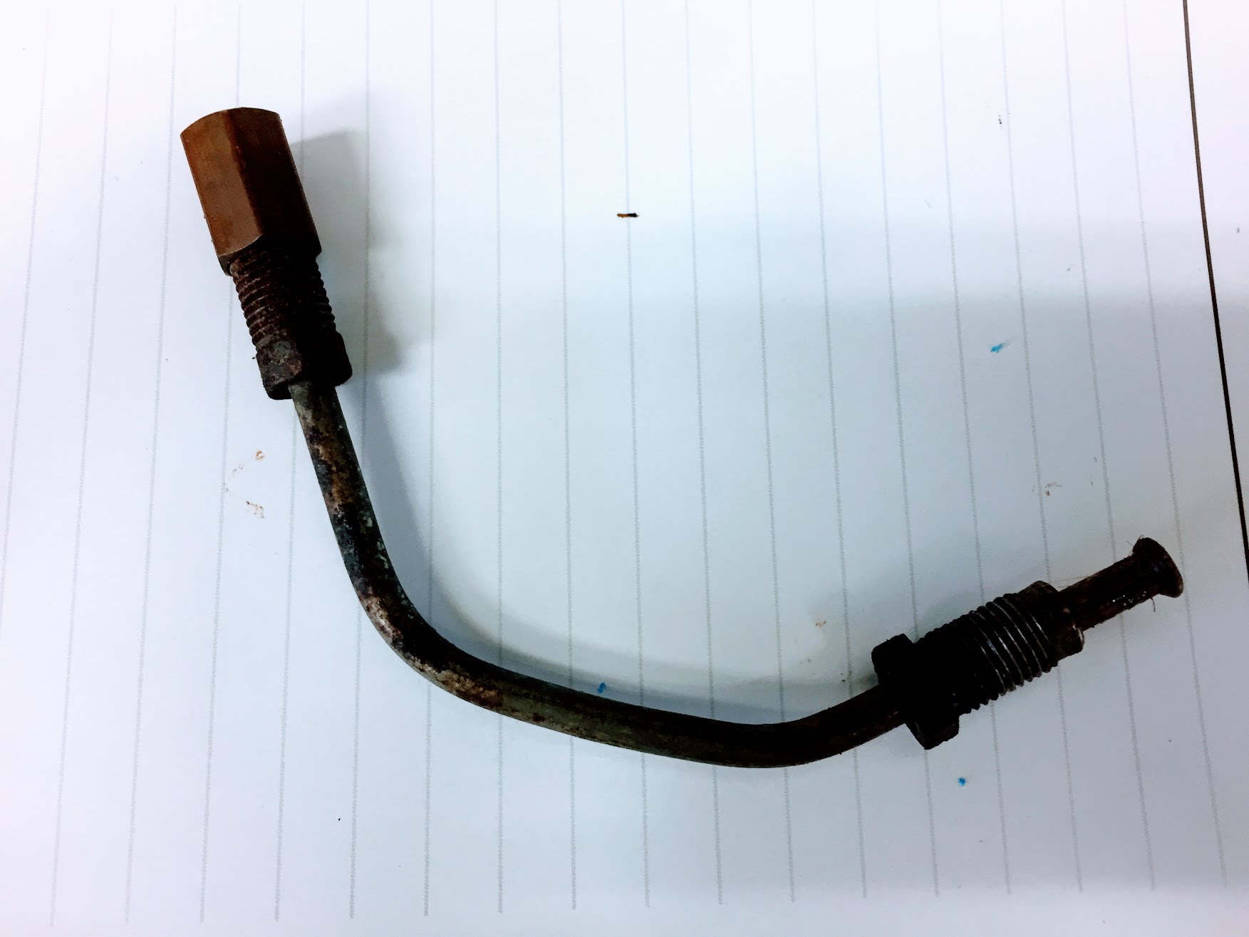
Master Cylinder Connection Pipe and Fittings
I am no expert on brake hydraulics, but it seemed to me that the use of the connection pipe introduces at least three additional opportunities for fluid leaks as compared to a direct mounting of the brake pipe from the master to the 4-way junction or union.
Consequently, I decided to cut the end of the hard pipe coming from the 4-way union, fit a new SAE fitting nut, re-flare the end of the pipe with a new double flare and screw the pipe directly into the master. To make this easier to accomplish, I rotated the master the 180 degrees.
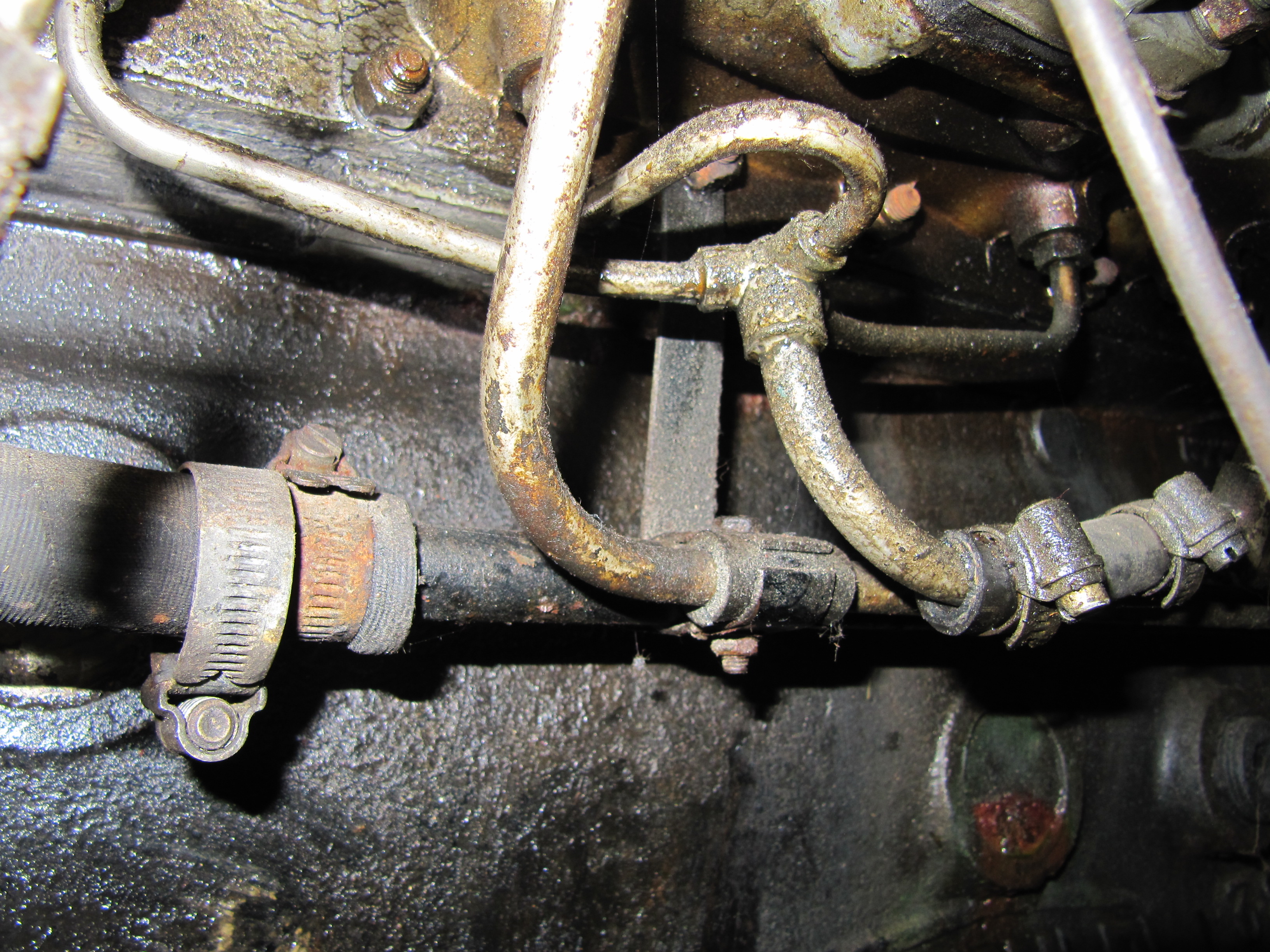
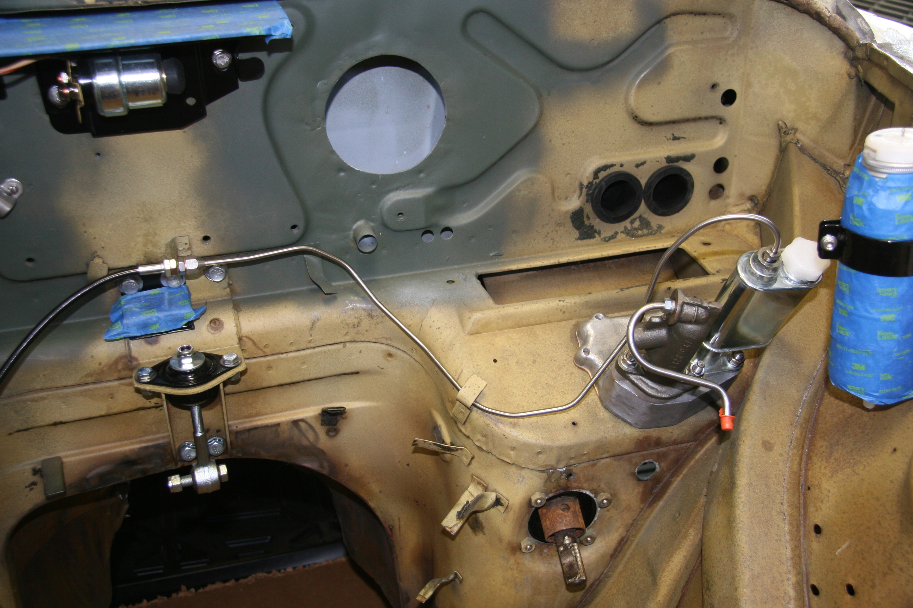
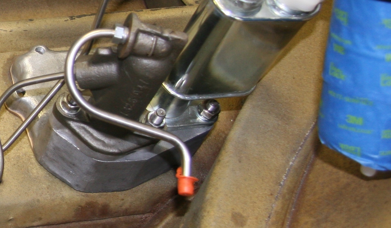
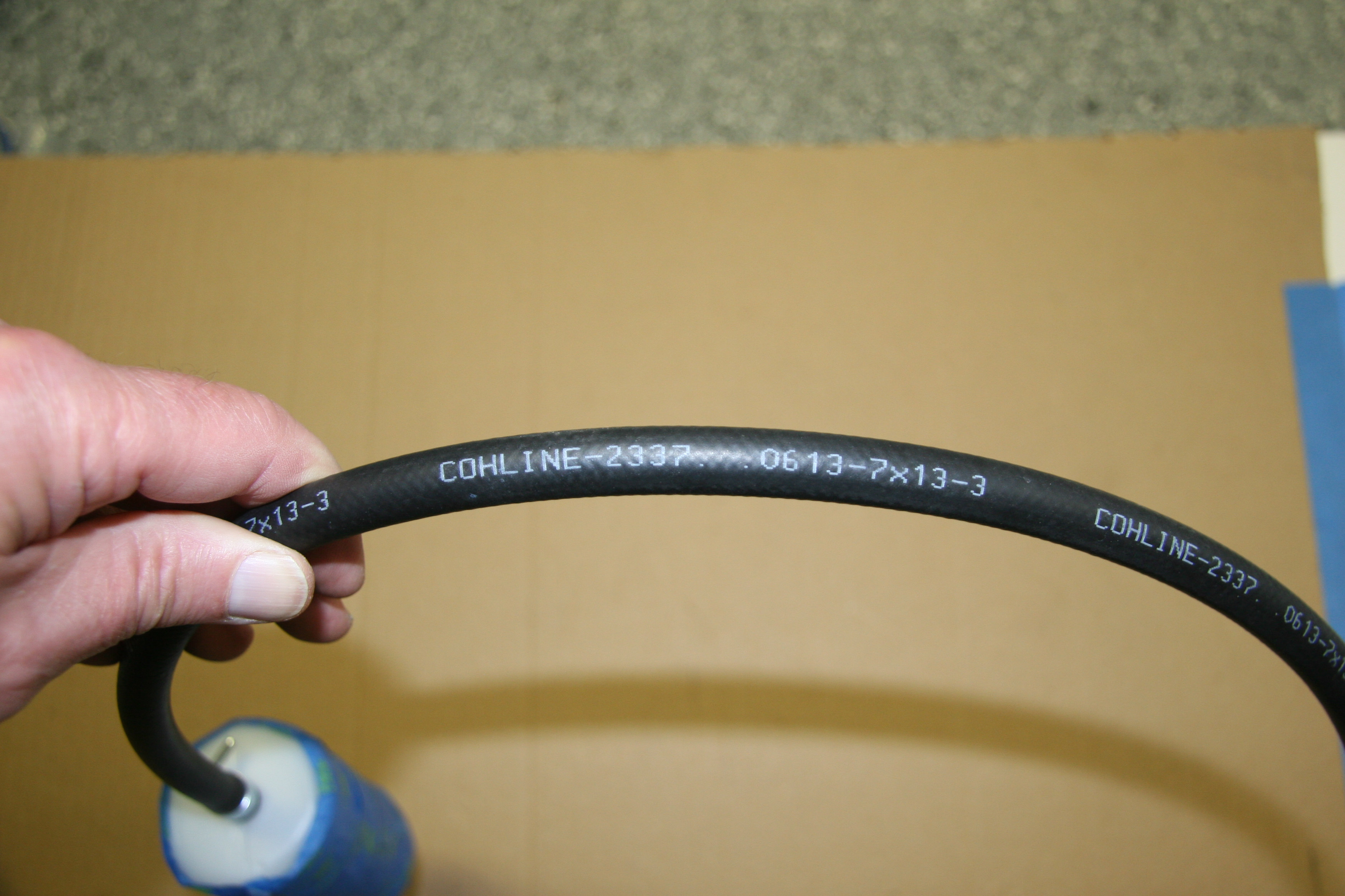
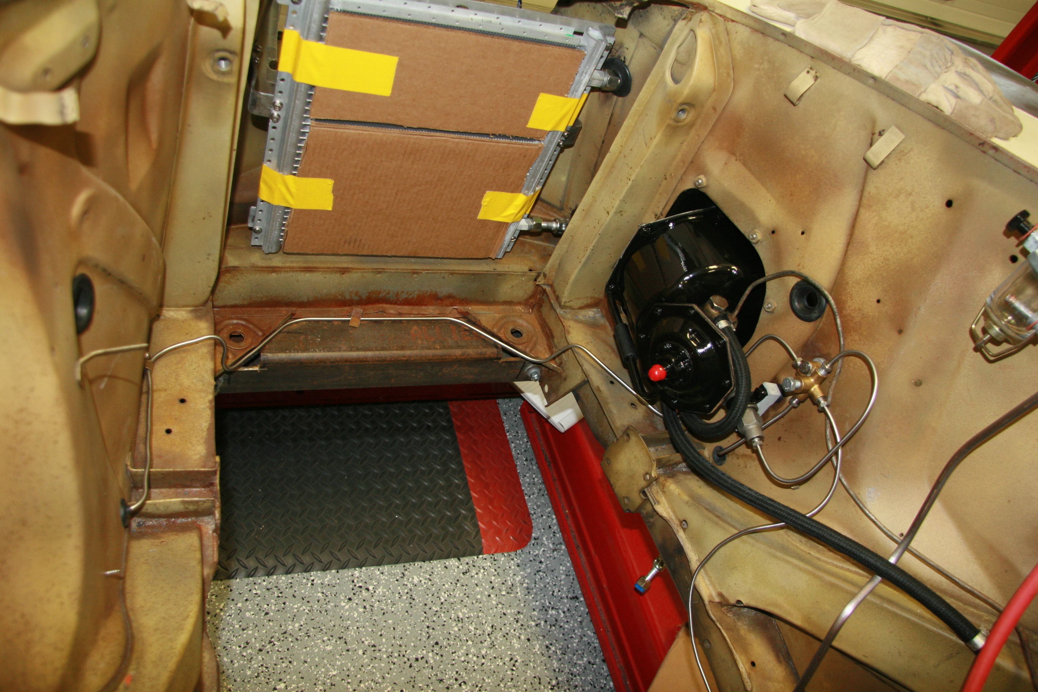
Brake Pipe from Reservoir Through Flexible Hose to Master Cylinder – This short pipe is joined to a hose specifically designed for use with hydraulic fluid that connects to the brake fluid reservoir. The hose was sourced from SNG Barratt COH Line – 2337, 0613-7 x 13-3. SNG Barratt supplied a 5/8″ clip to secure the hose, but I found the clip to be too large and instead used 11-13 mm clips at both ends of the hose. The plastic reservoir is taped to keep it clean while mounted in the car during restoration.
Brake Pipe From Master Cylinder to Flexible Hose
Brake fluid Hose from Reservoir to Master Cylinder Pipe

Brake Fluid Hose from Reservoir to Master Cylinder Pipe
Brake Pipe From Master Cylinder to Four-Way Junction – This pipe curves around the firewall, along the RH engine bay valance and connects with the junction. It is held in place by two welded folding clips.
Brake Pipe from Servo to the Four-Way Junction
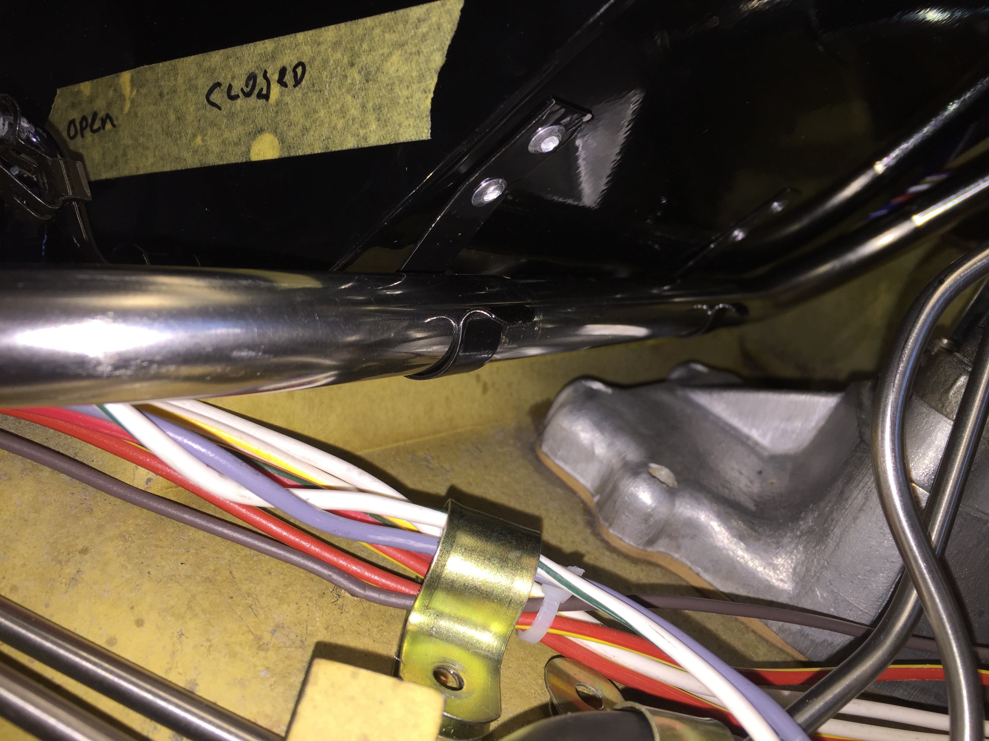
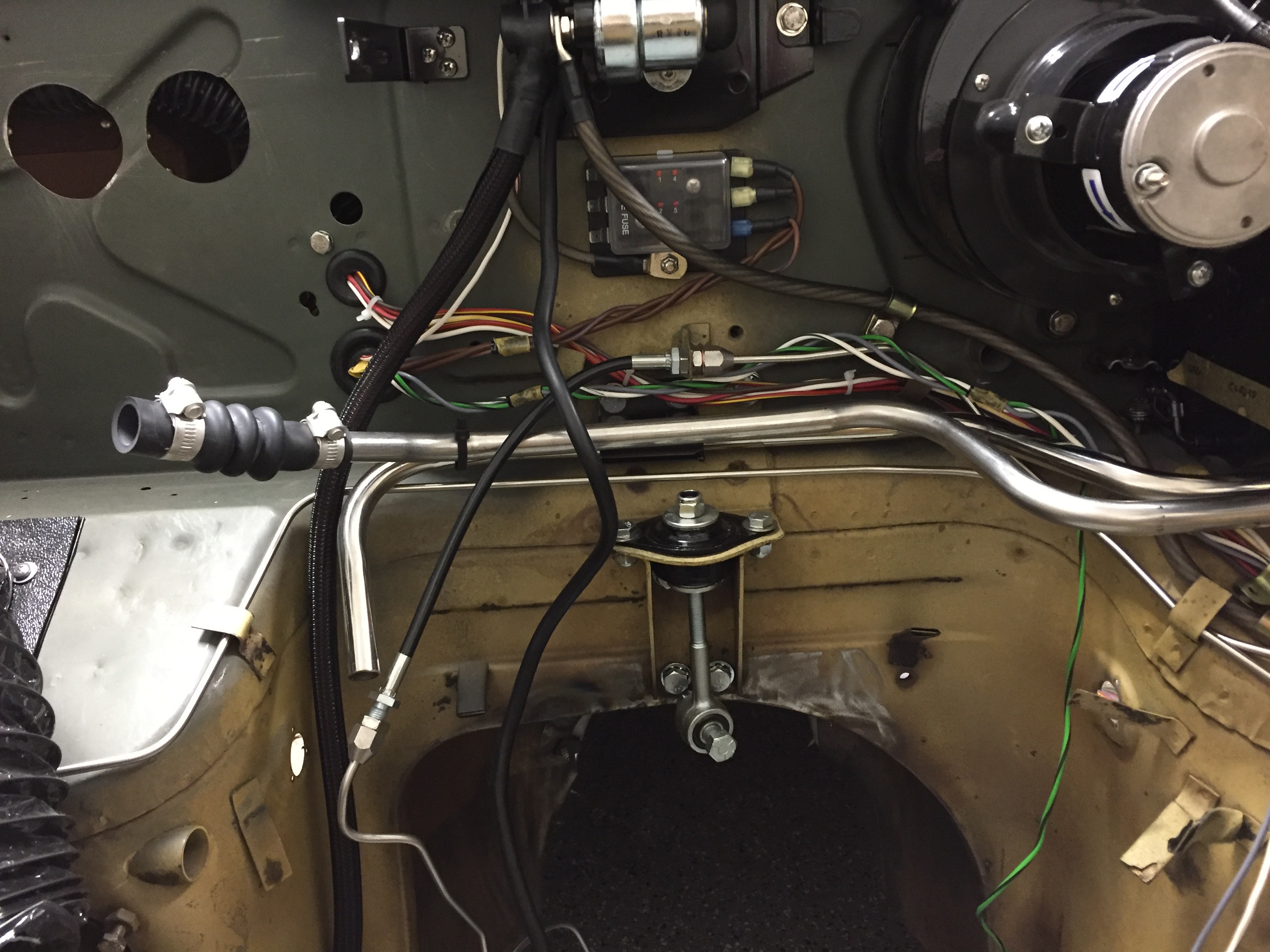
Brake pipe to rear axle from from-way adapter – A long pipe running from the four-way adapter, along the RH frame rail to a metal tab fitting welded to the body at the end of the frame connects to a flexible Goodridge hose to the rear axle. This pipe shares routing with the full line and battery cable, all secured by a series of stainless steel double clips.
Fuel and brake Lines routed to Rear
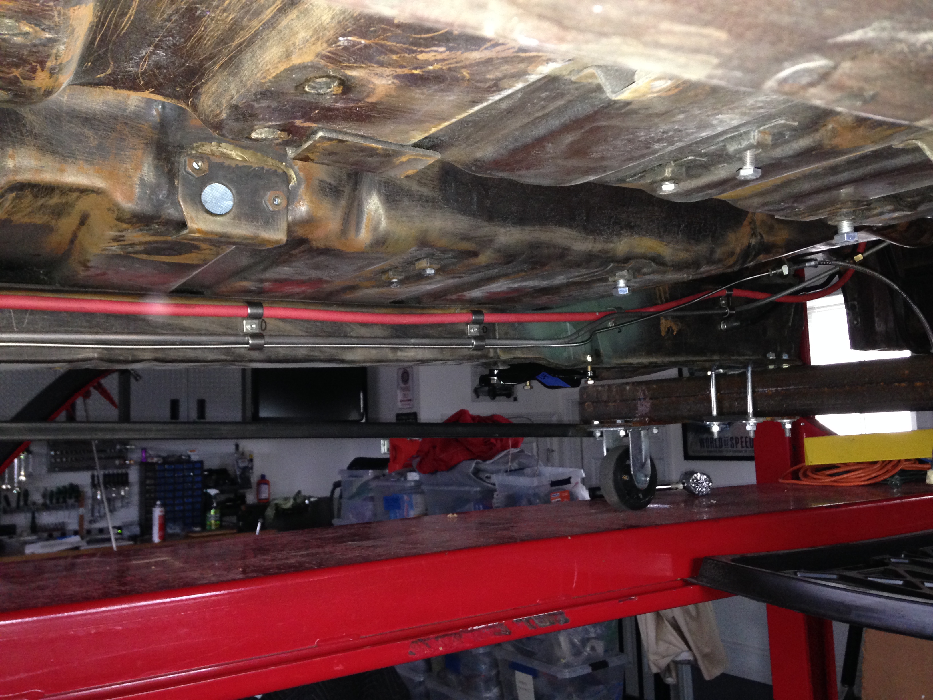
Fuel Line, Brake Pipe, Battery Cable Routing
Brake Line Connection to Flexible Hose
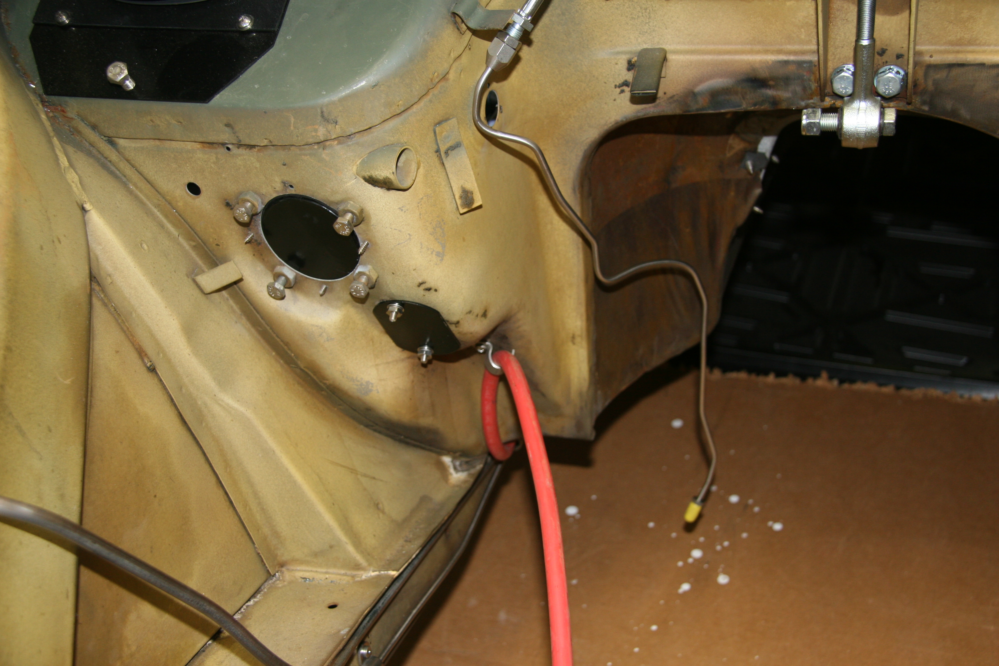
LH Front Brake Pipe – This line runs from the four-way adapter, around the front frame under the radiator, and through a LH engine bay valance rubber grommet, to a welded metal clip on the outside of the valance where it joins a Goodridge flexible hose to the brake caliper. It is secured by three white zinc 1/4″ clips with 7/32″ holes and stainless self-tapping screws. A bendable tab at the front center of the frame helps to hold the pipe in place.
LH Brake Pipe to Junction
RH Front Brake Pipe – This line runs from the four-way adapter, through a RH engine bay valance rubber grommet, to a metal welded clip on the outside of the valance where it joins a Goodridge flexible hose to the brake caliper. It is secured by one white zinc 1/4″ clip with a 7/32″ hole and a stainless self-tapping screw.
RH Front Brake Pipe From Four Way Junction to Caliper

RH Front Brake Pipe From Four Way Junction to Caliper
Brake Pipe Tools
I will be using new pipe hardware for the Jag. This will require shaping the pipe (or straightening it), and while I have a few tools for this purpose, Brake Quip sells some very nice brake system tools and fittings.
http://www.brakequip.com/tools
Brake Fluid Container & Clip
The container and clip were replaced with new items including the filler cap and level indicator switch. The Clip has a distance piece through which a 1/4″ – 28 x 2 1/4″ hex head bolt, shake proof washer, and a hex nut are used to mount the container to the LH wing valance. A #10 -32 x 3/4″ machine screw, shake proof washer, flat washer and hex nut is used to tighten the container clamp. Both the clip and the distance piece were painted with gloss black POR-15.

Brake Fluid Container, Filler Cap & Level indicator Switch, Clip and Distance Piece
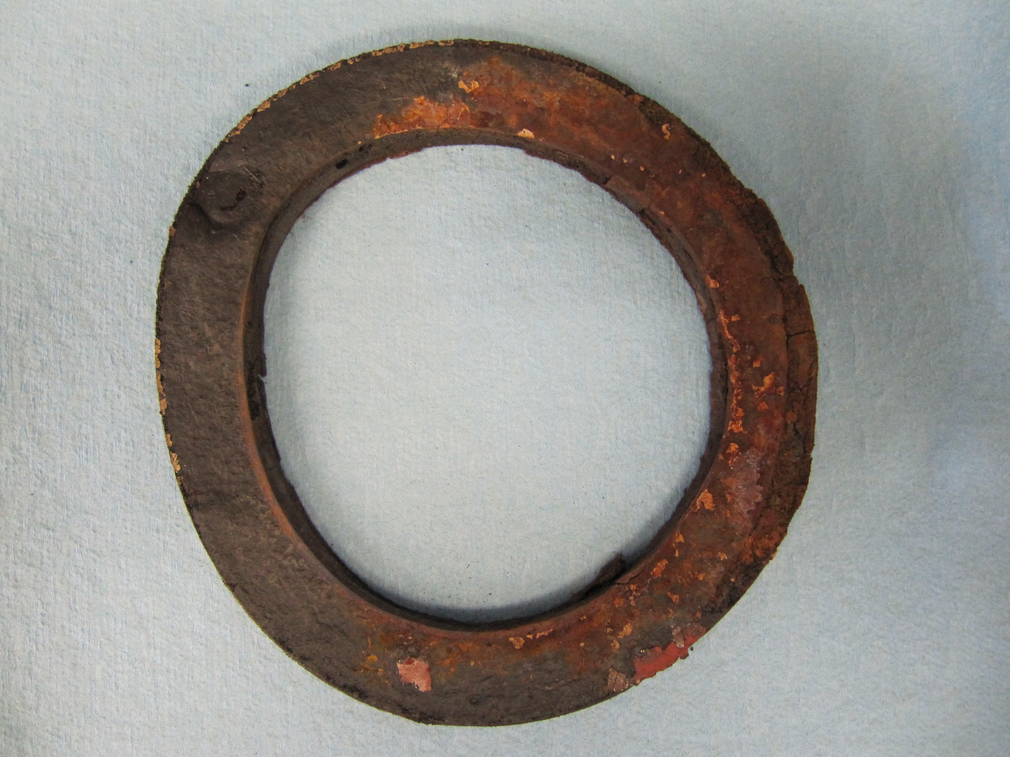
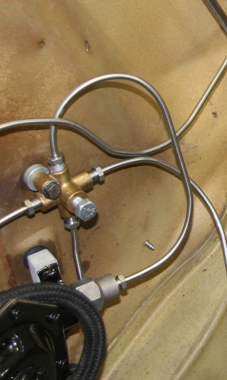
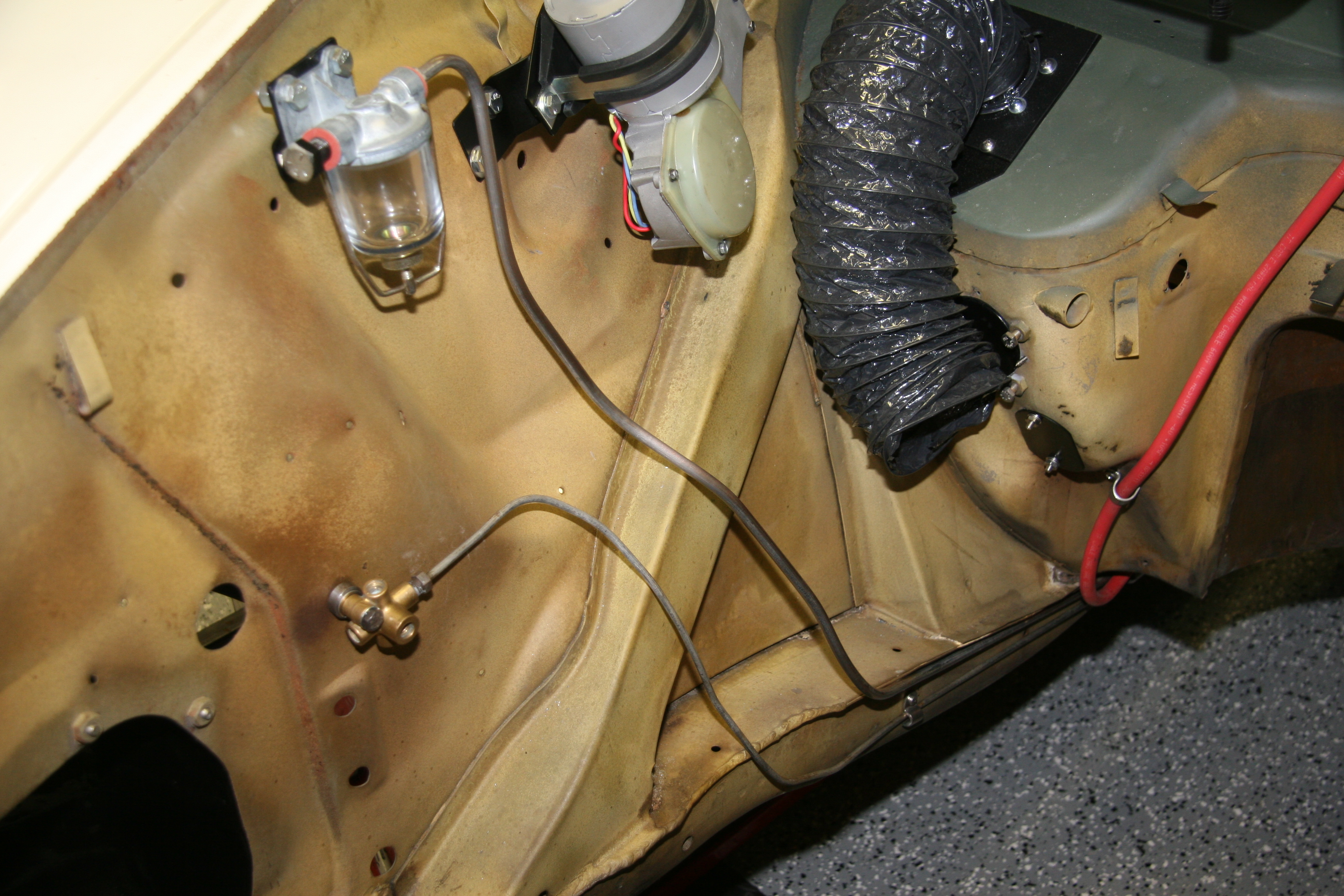
Brake Pipe 4-Way Adaptor
This component simply needed cleaning and it was ready to use once more:

- Brake Pipe 4-Way Adaptor

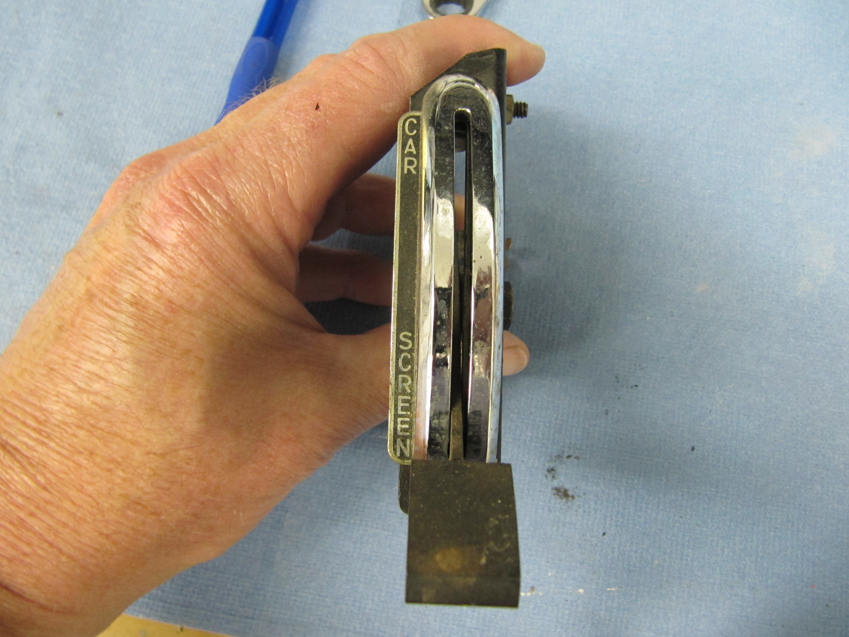
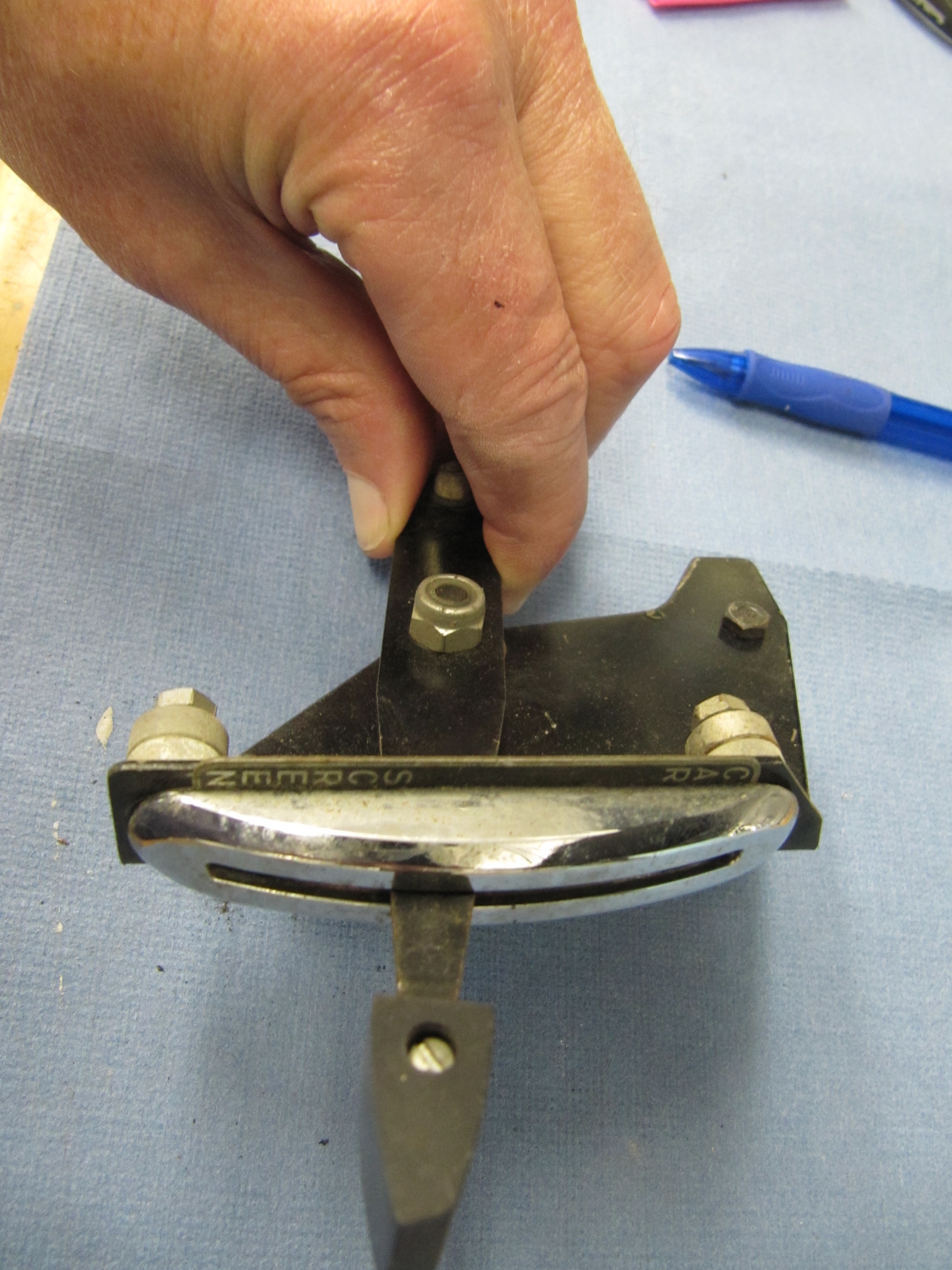
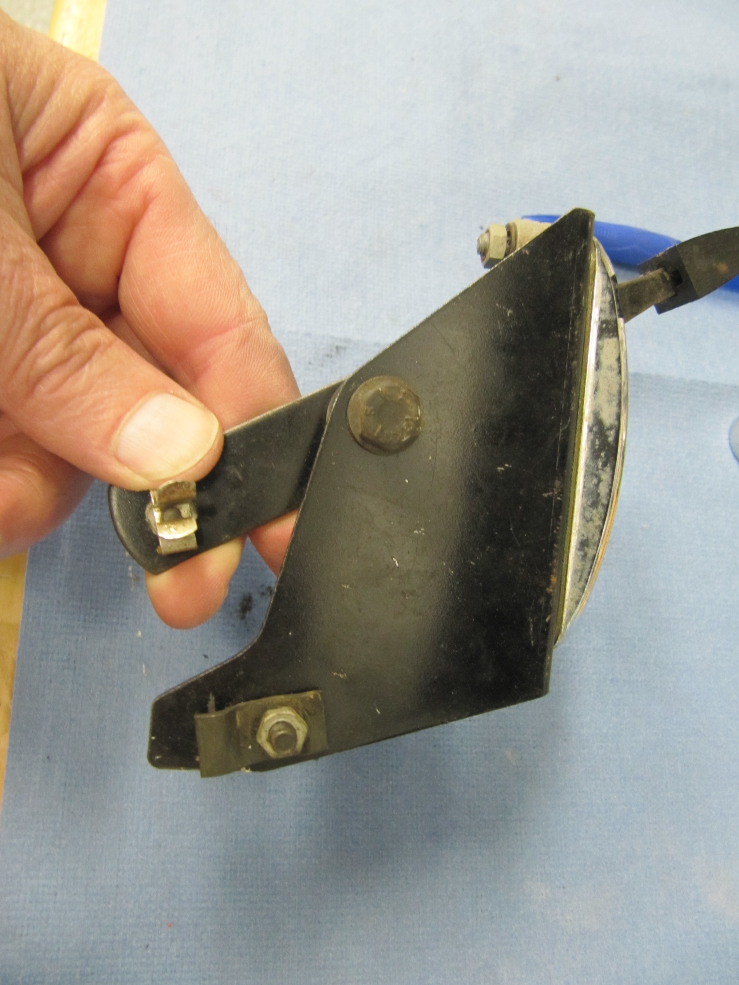
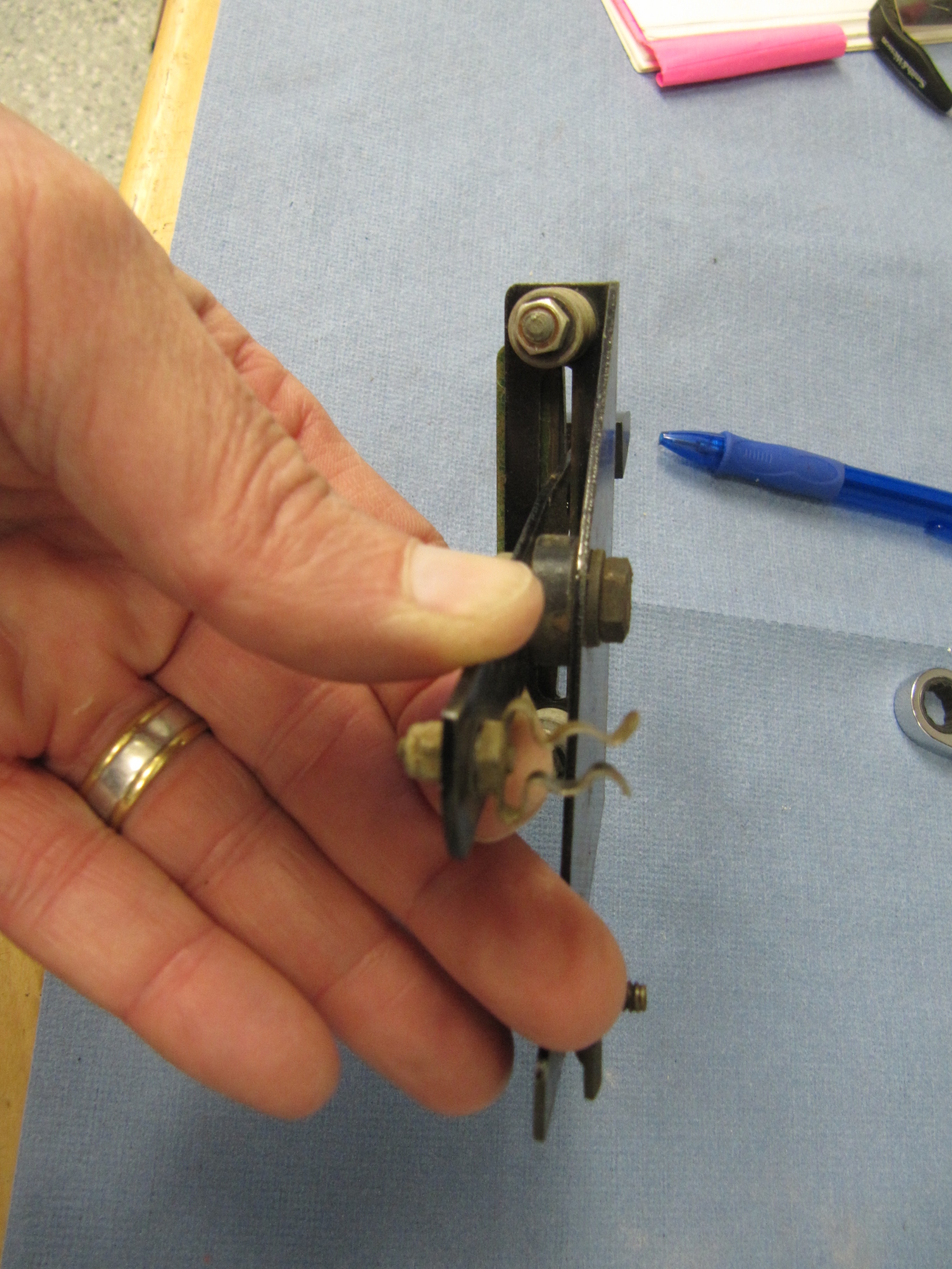
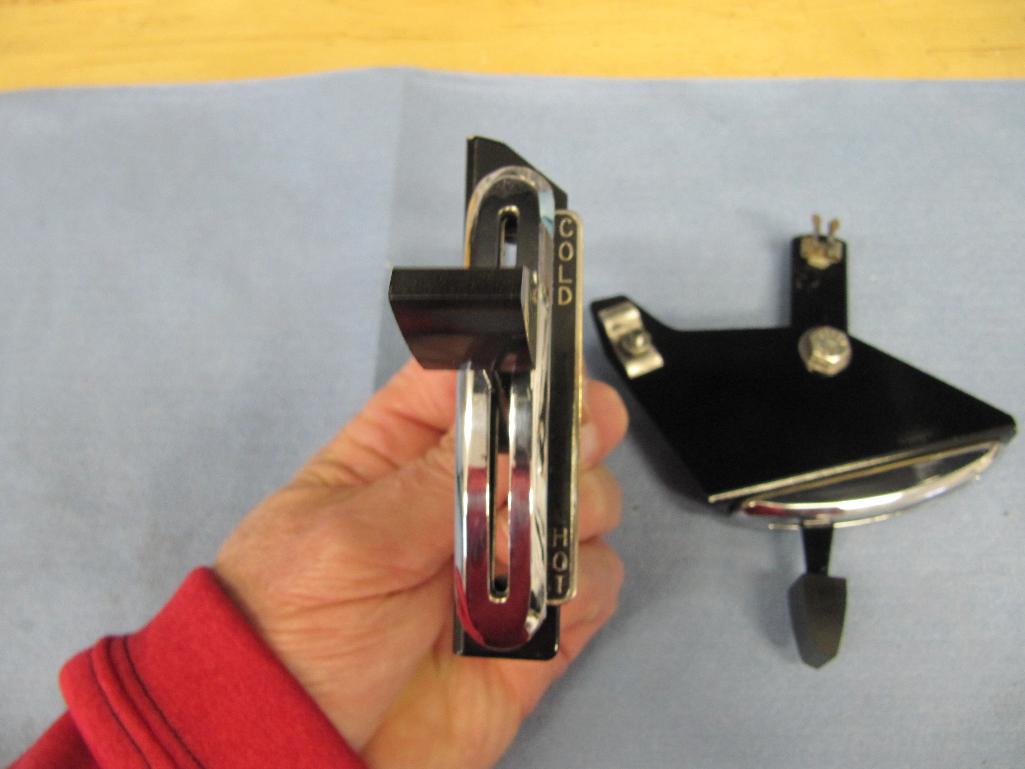
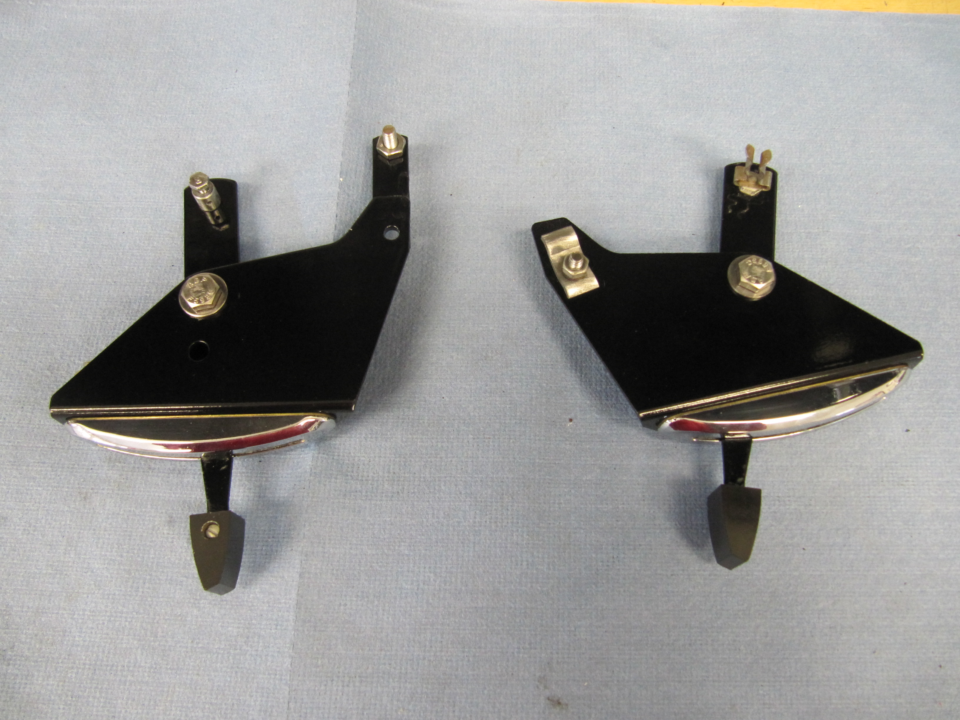
Mechanical Brake Switch
The MK2 originally used an hydraulic brake switch to activate the rear brake lights when the brakes are applied. The hydraulic switches currently available seem to experience a higher than normal failure rate. I encountered this same issue with my Austin-Healey 3000. In the Healey I replaced the hydraulic switch with a plug in the 4-way adaptor and installed a mechanical switch at the brake pedal. The wiring is the same as for the electrical switch. The mechanical switch was sourced from Watson’s Streetworks.
Watson’s Streetworks Mechanical Brake Switch
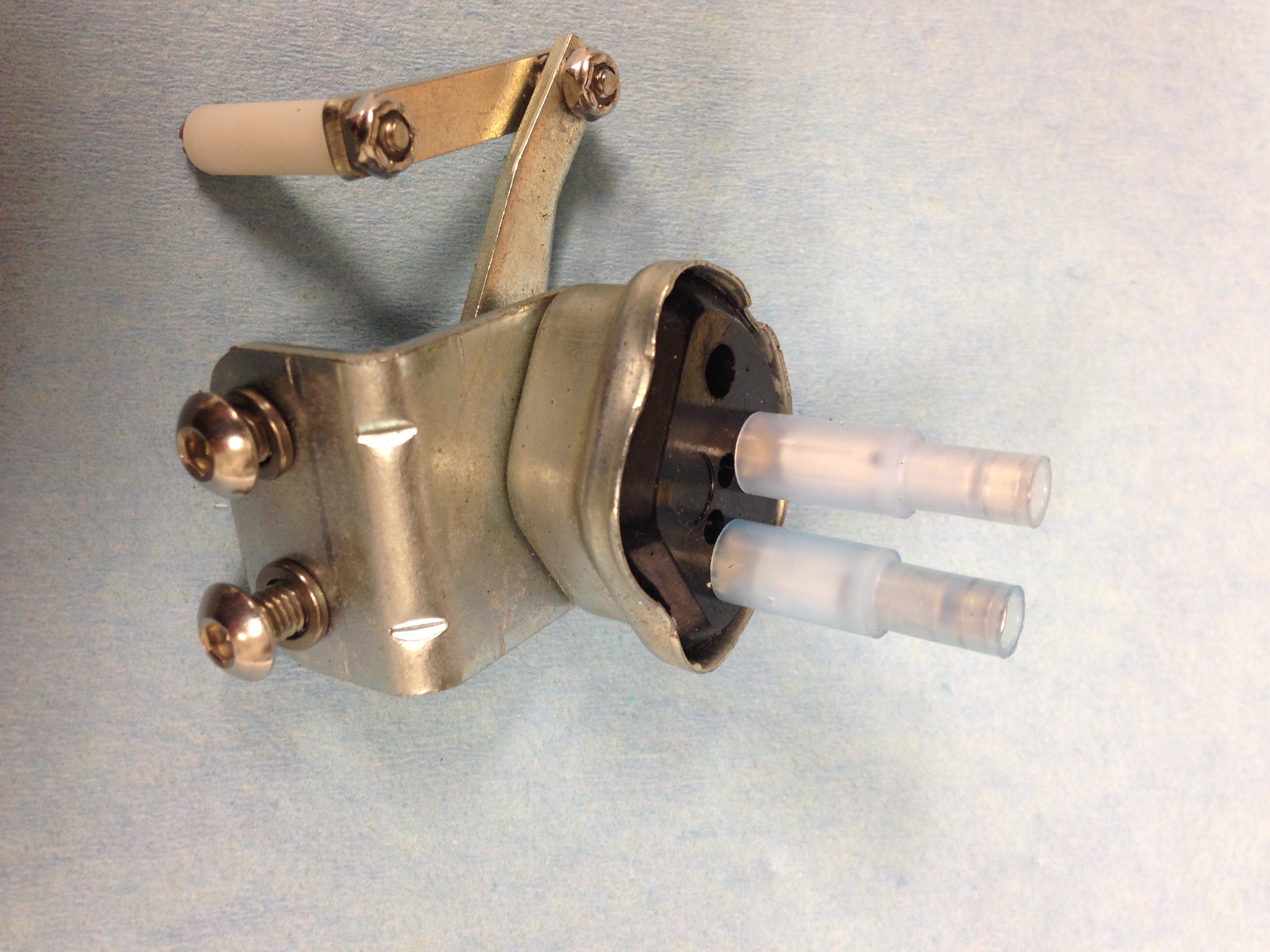
Watson’s Streetworks Mechanical Brake Switch
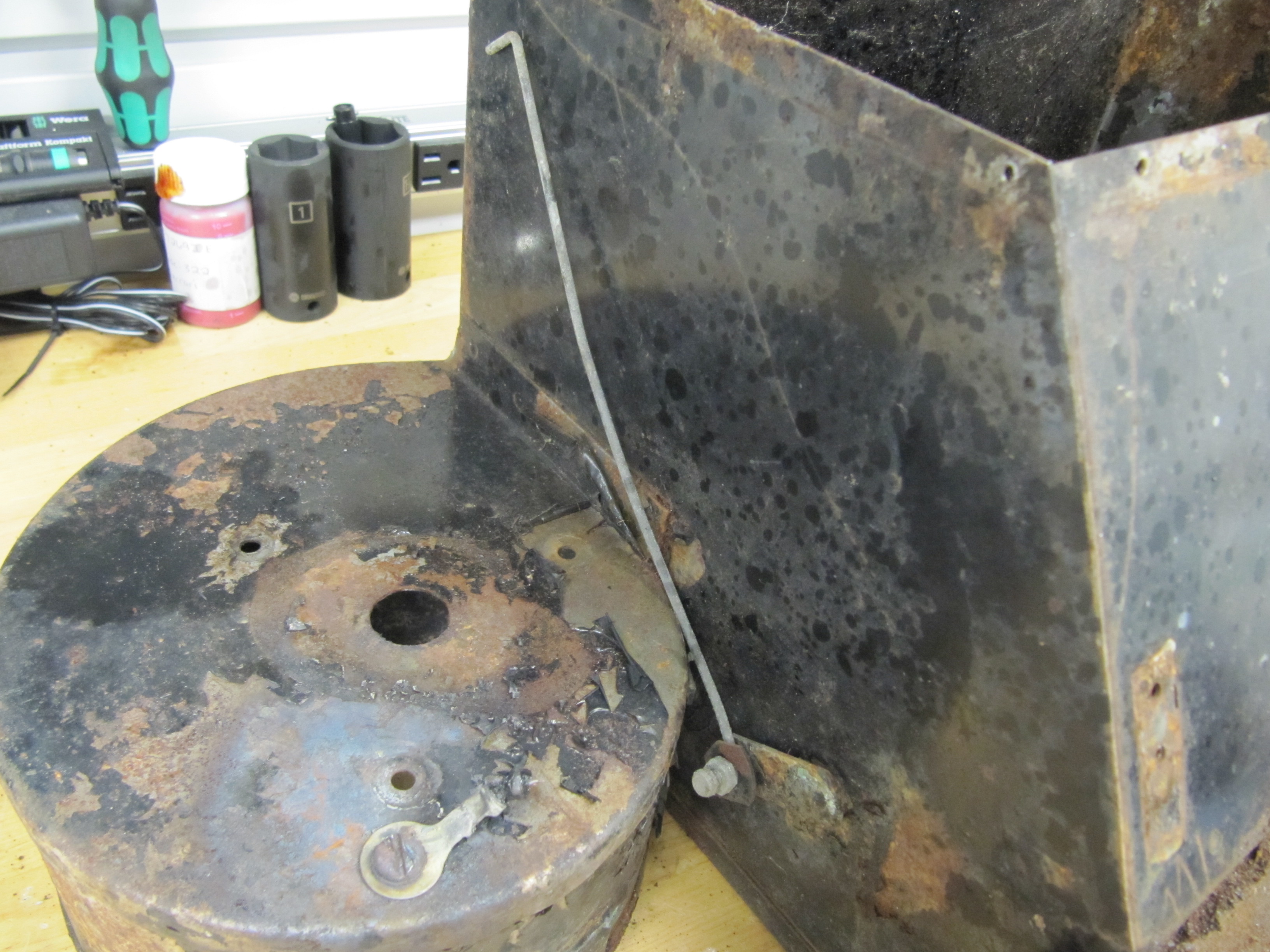
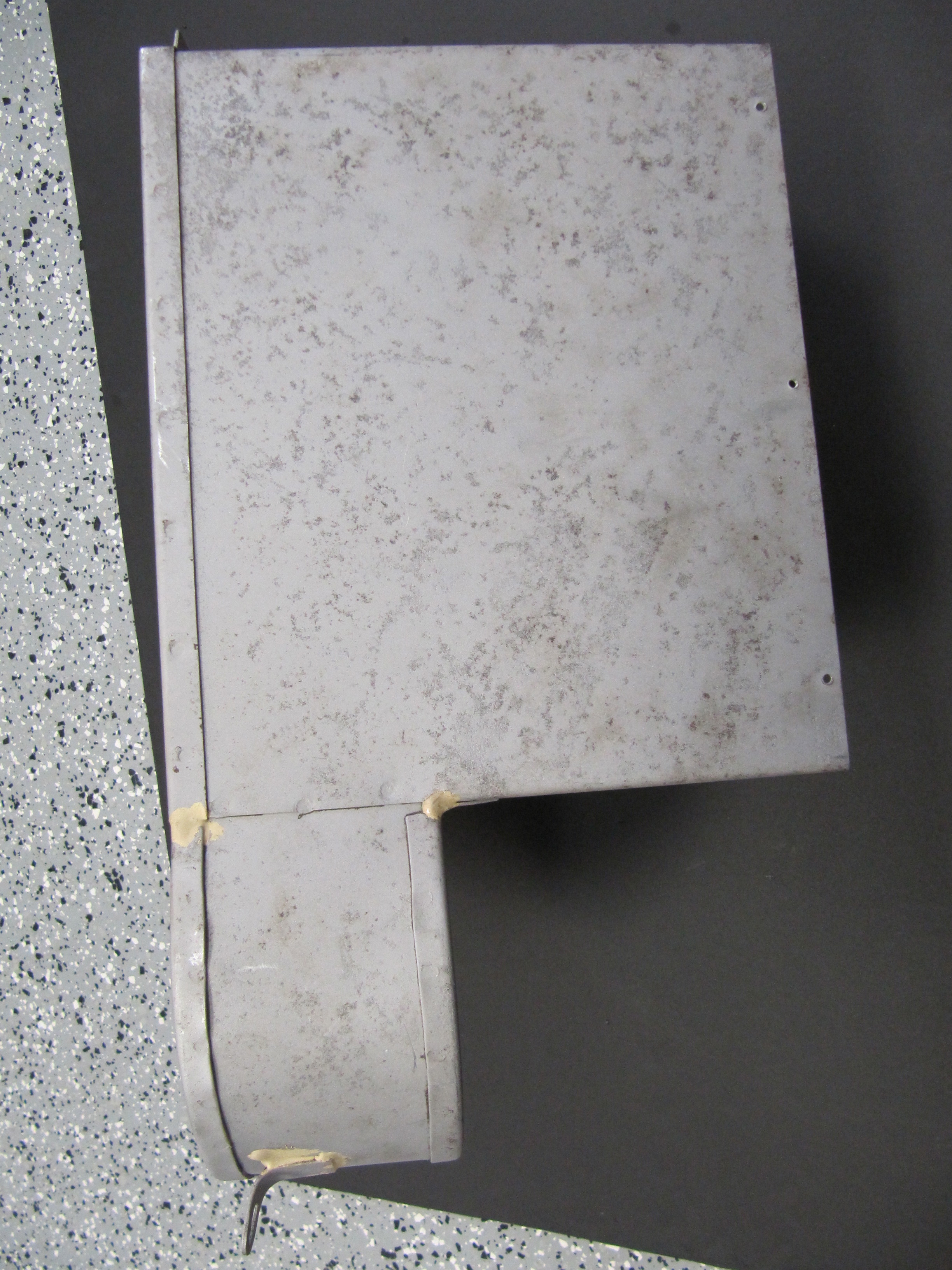
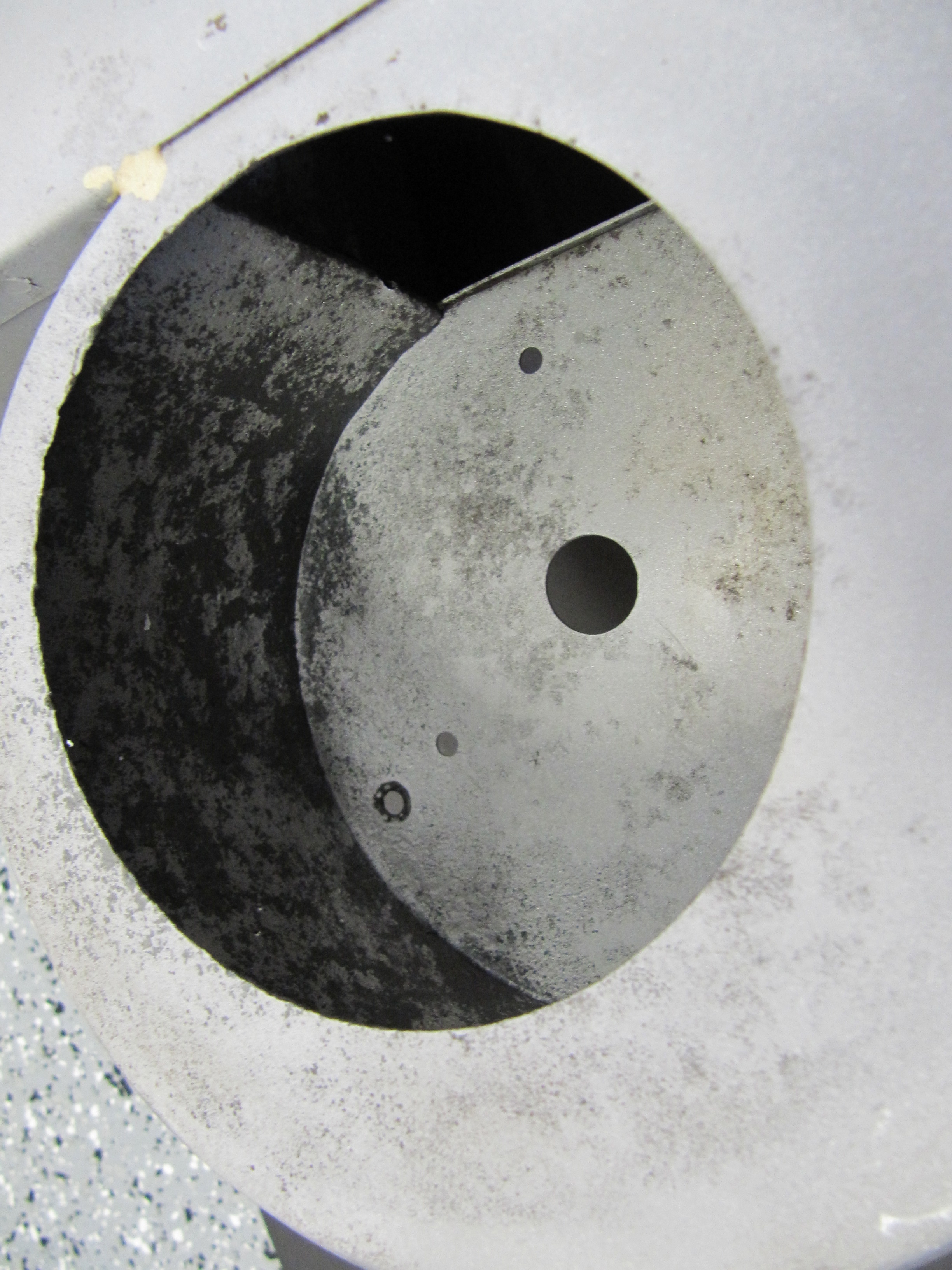
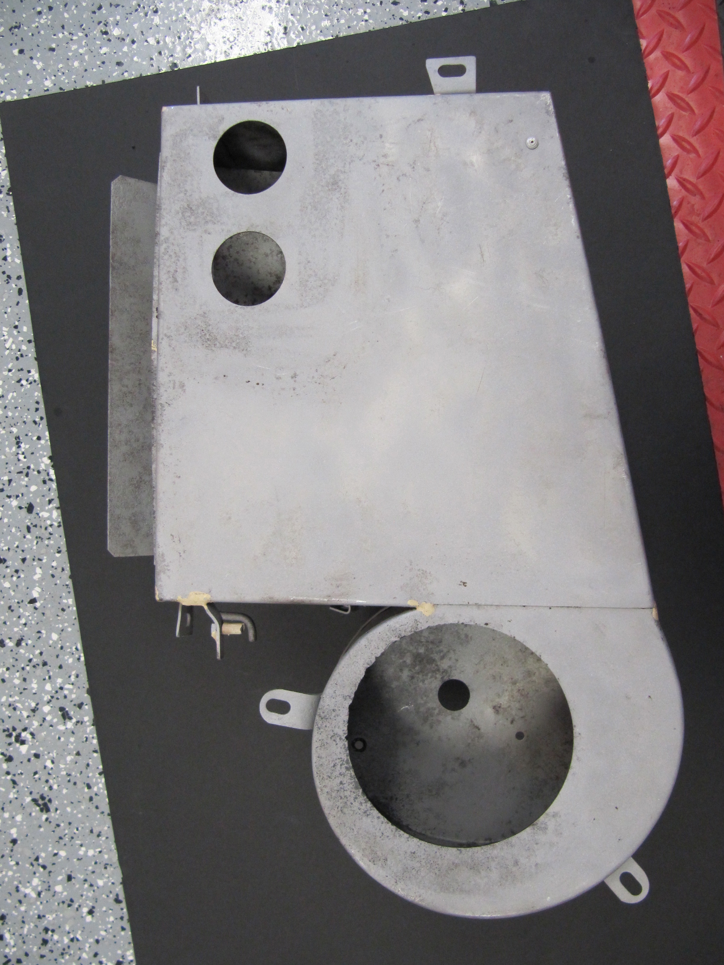
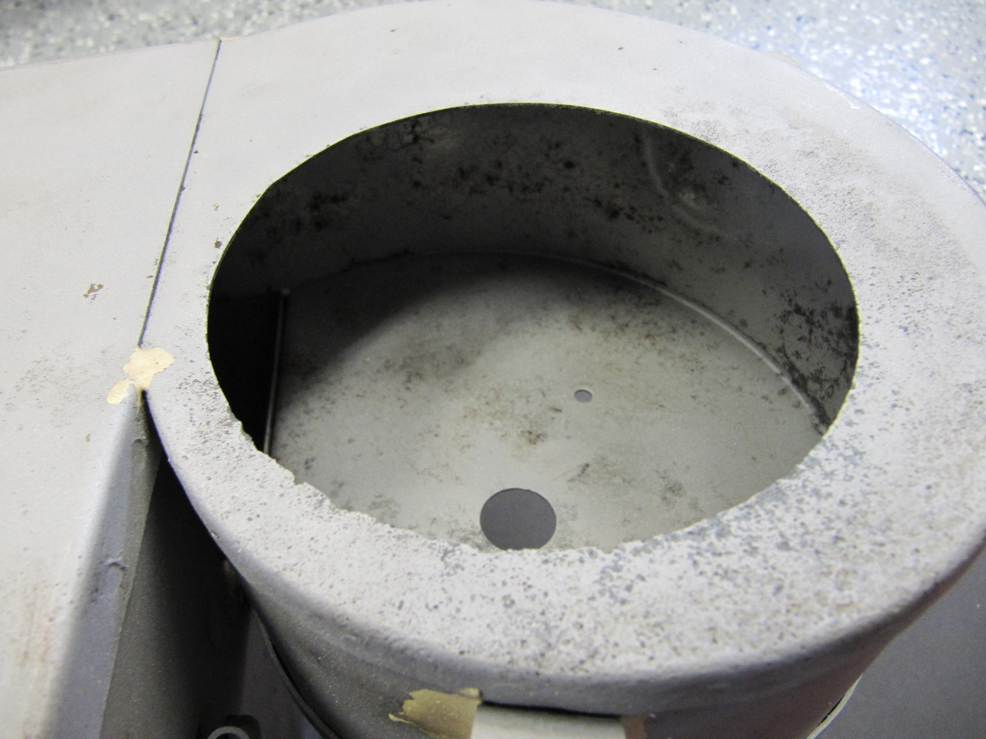
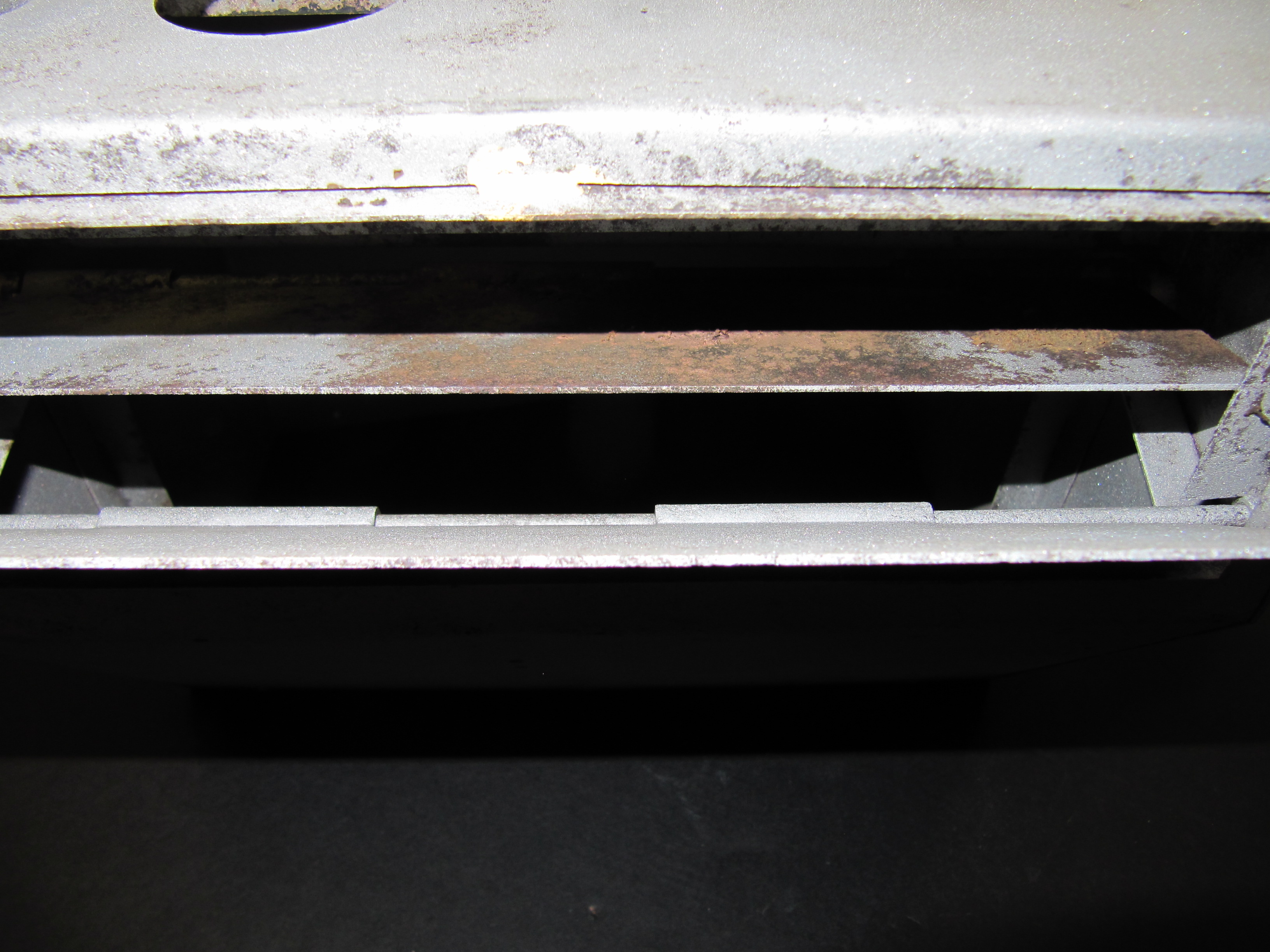
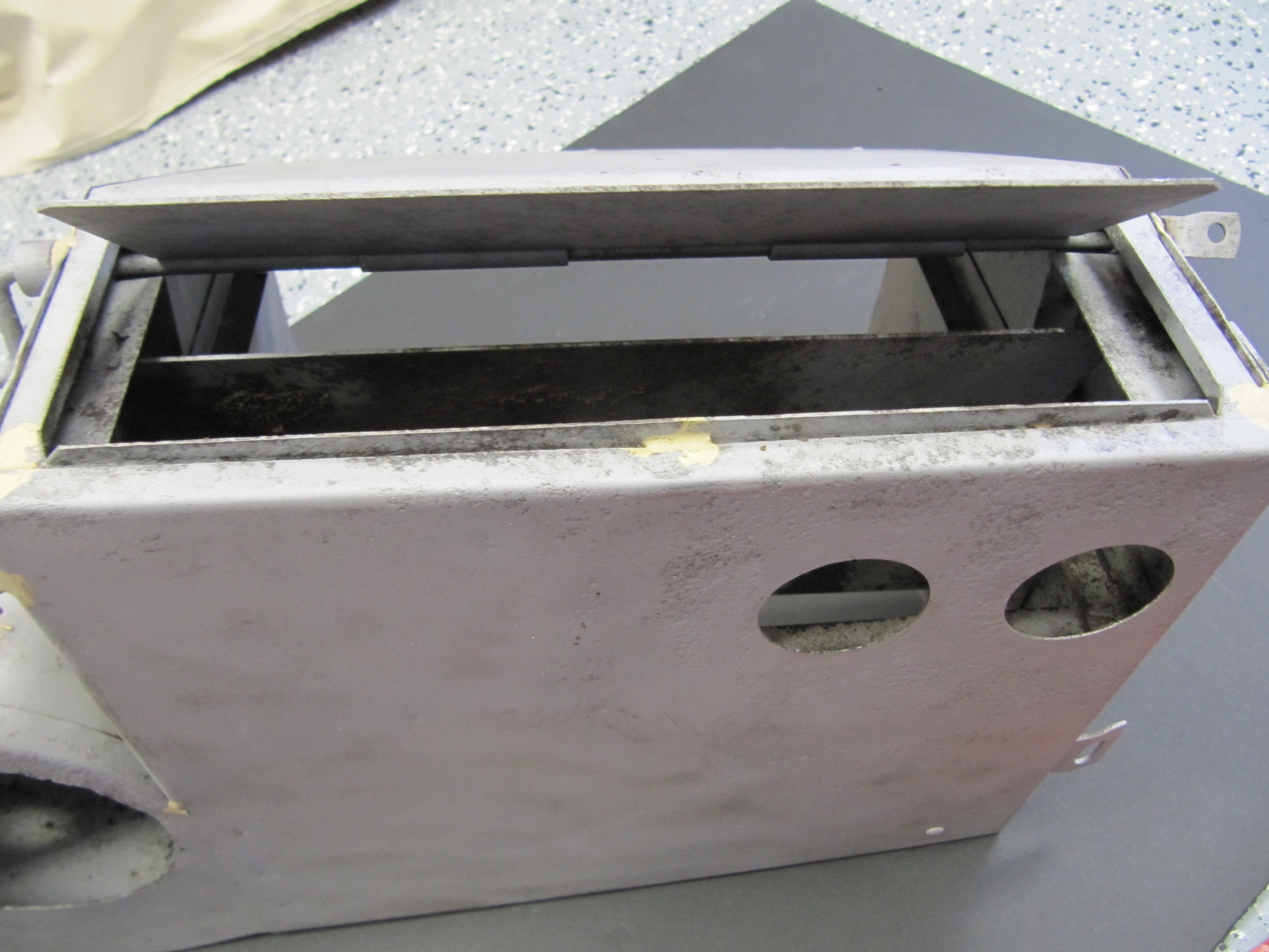
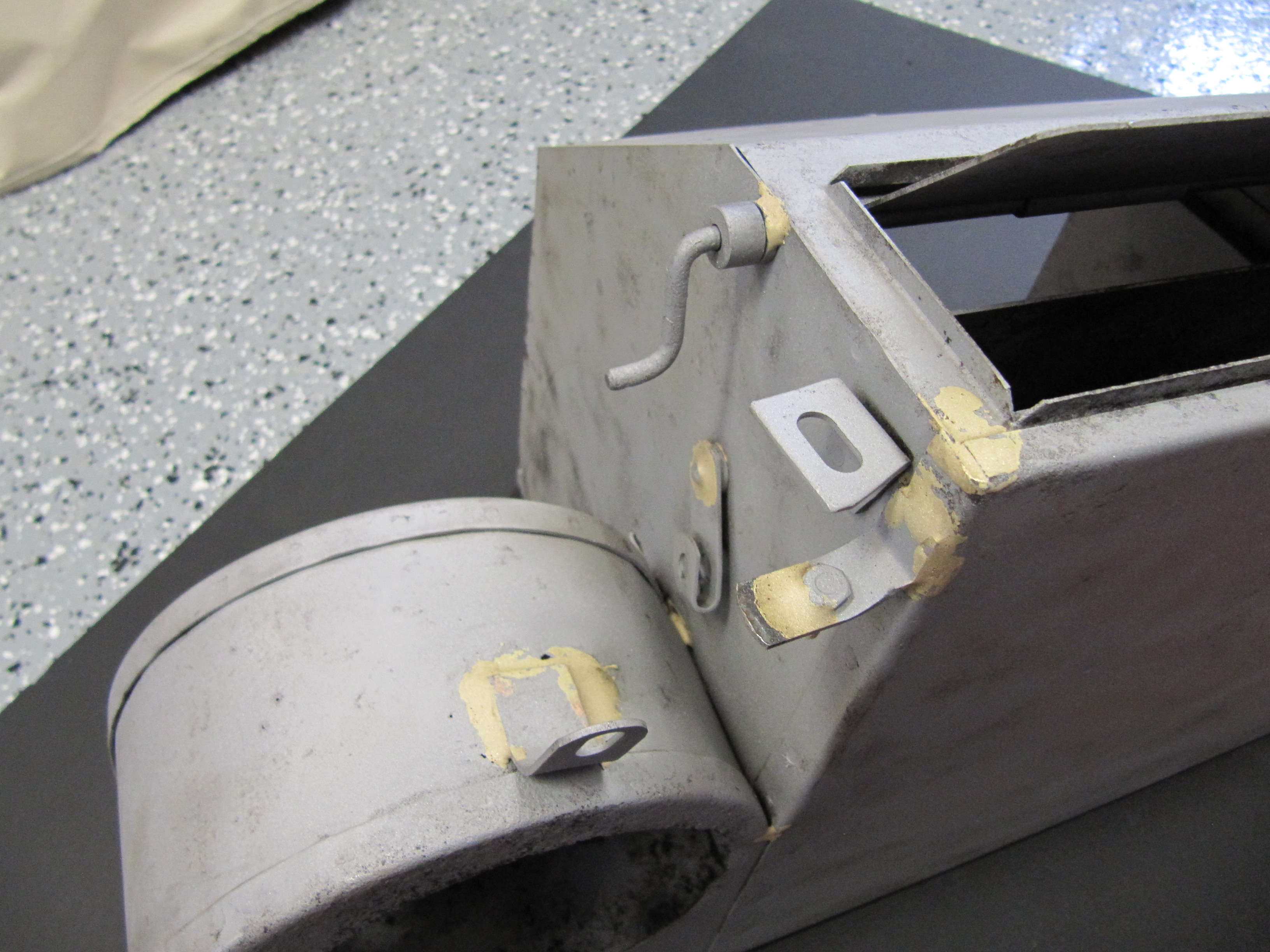
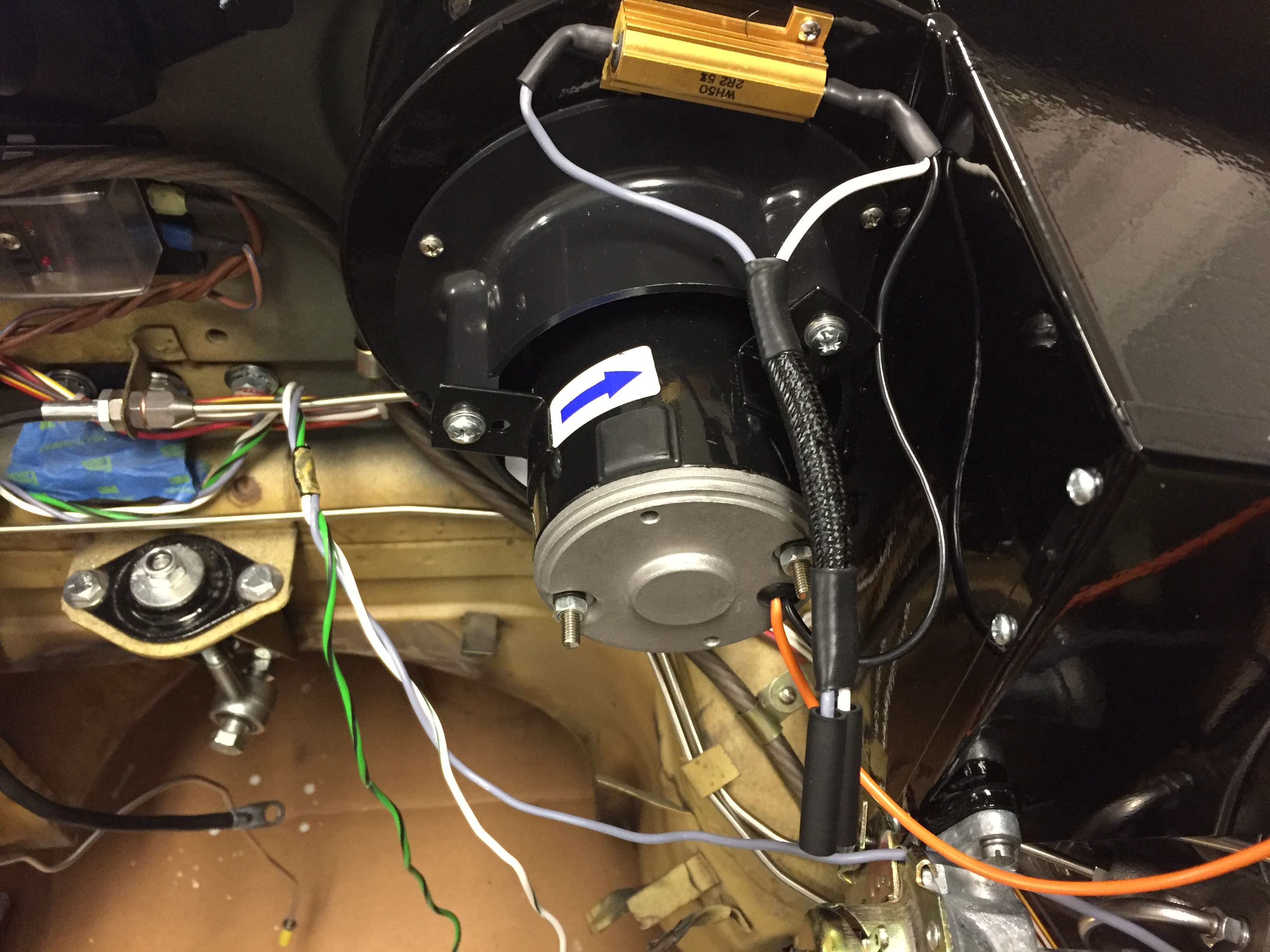
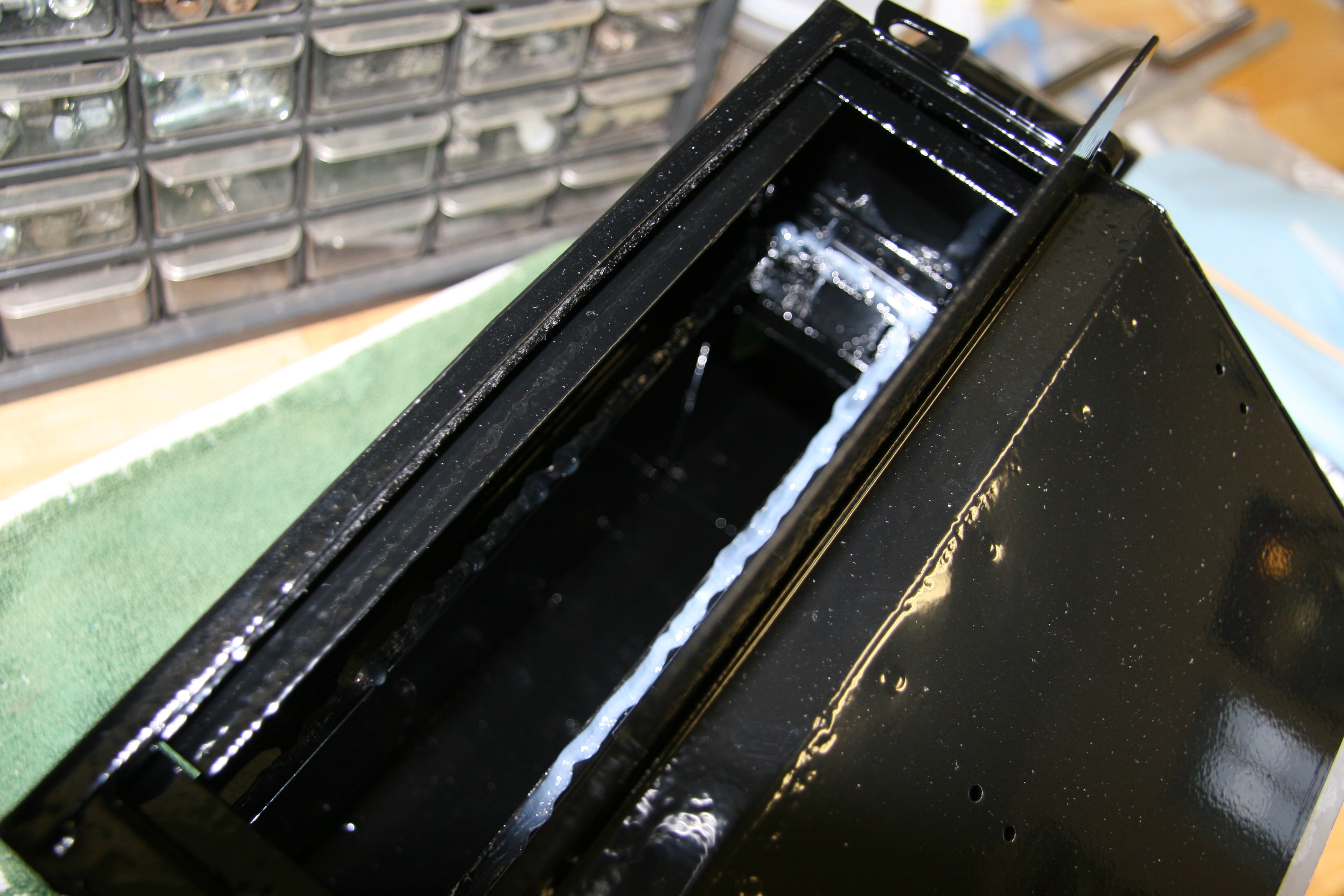
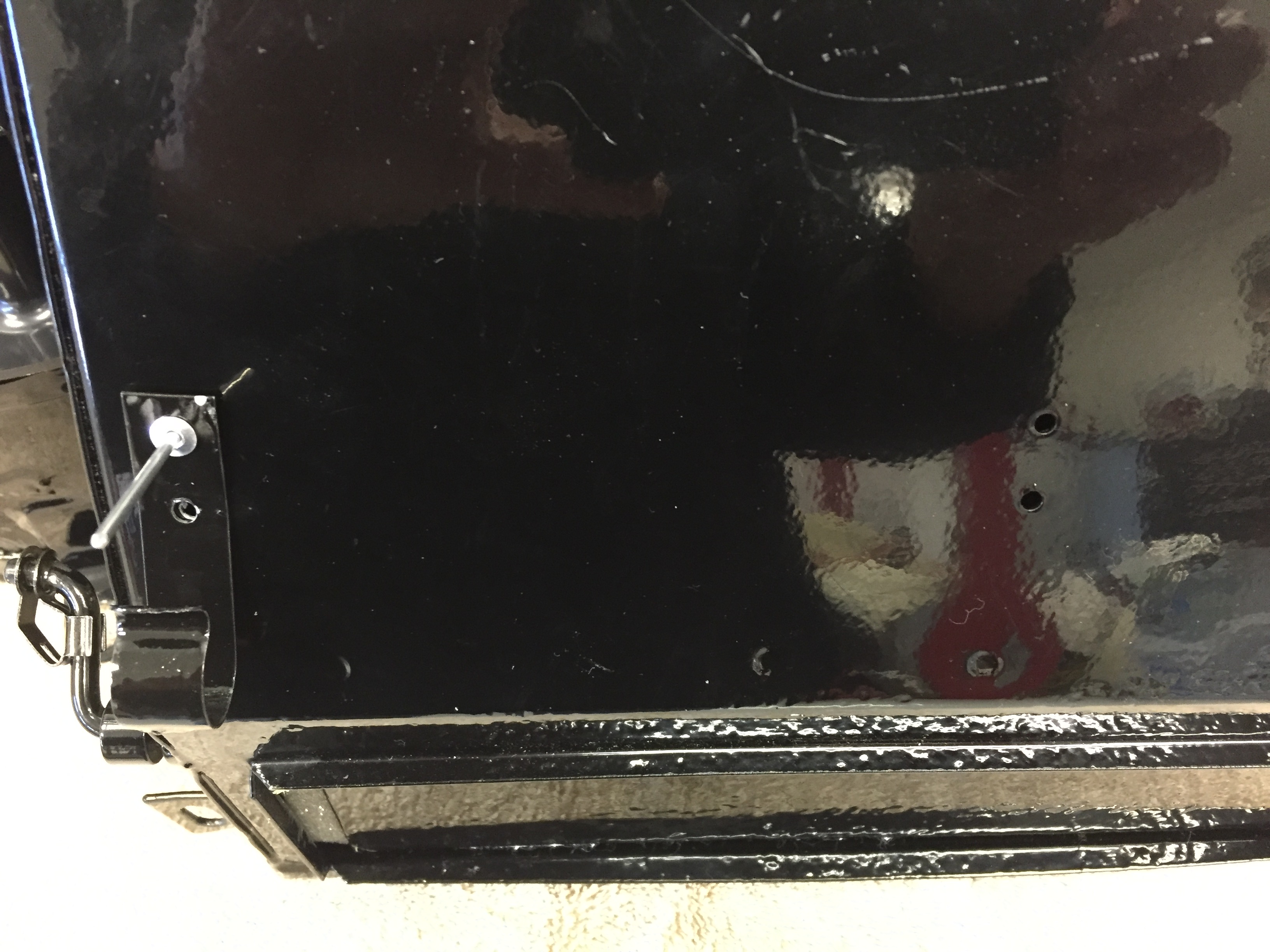
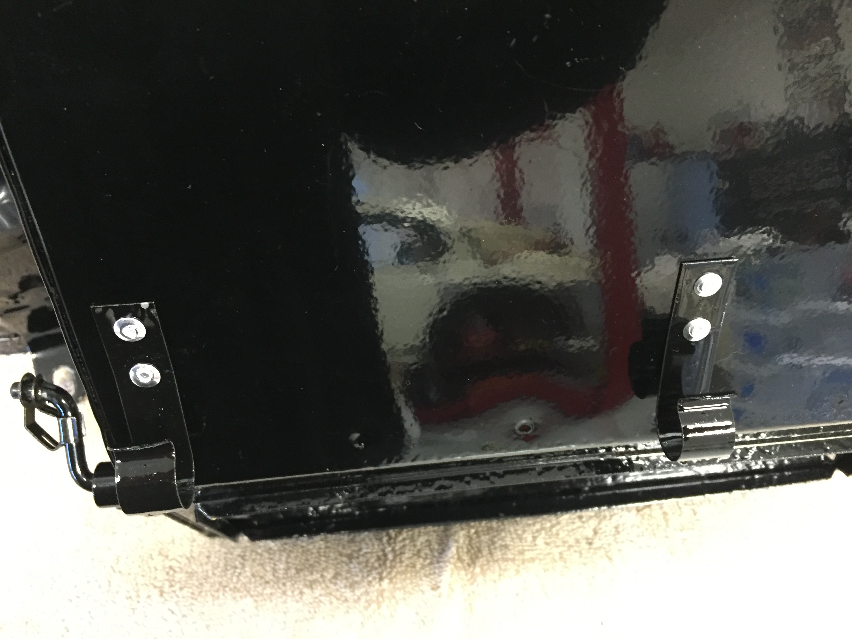
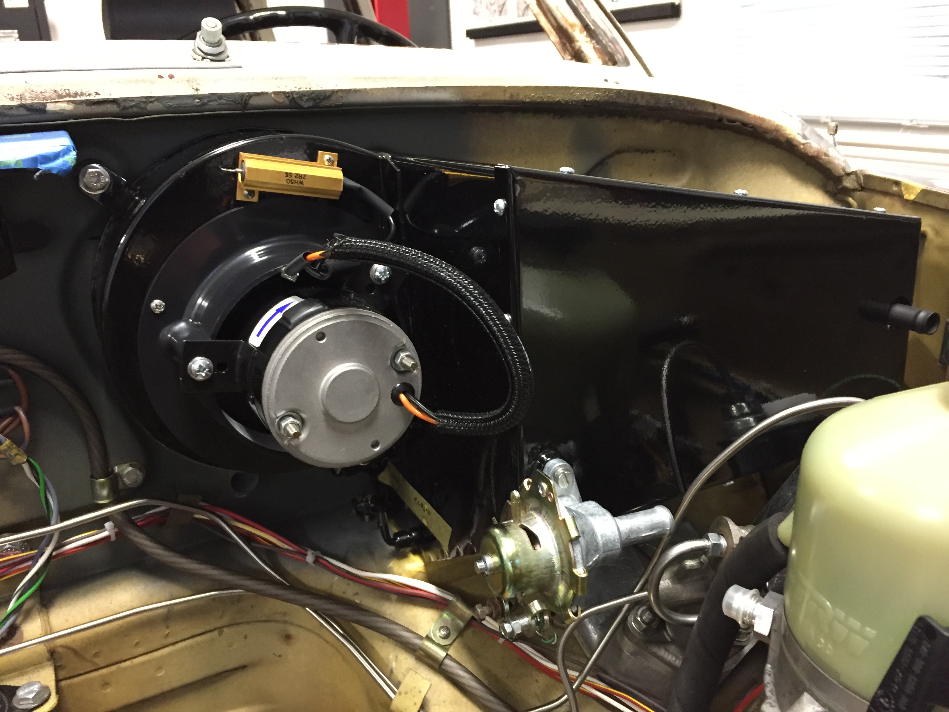
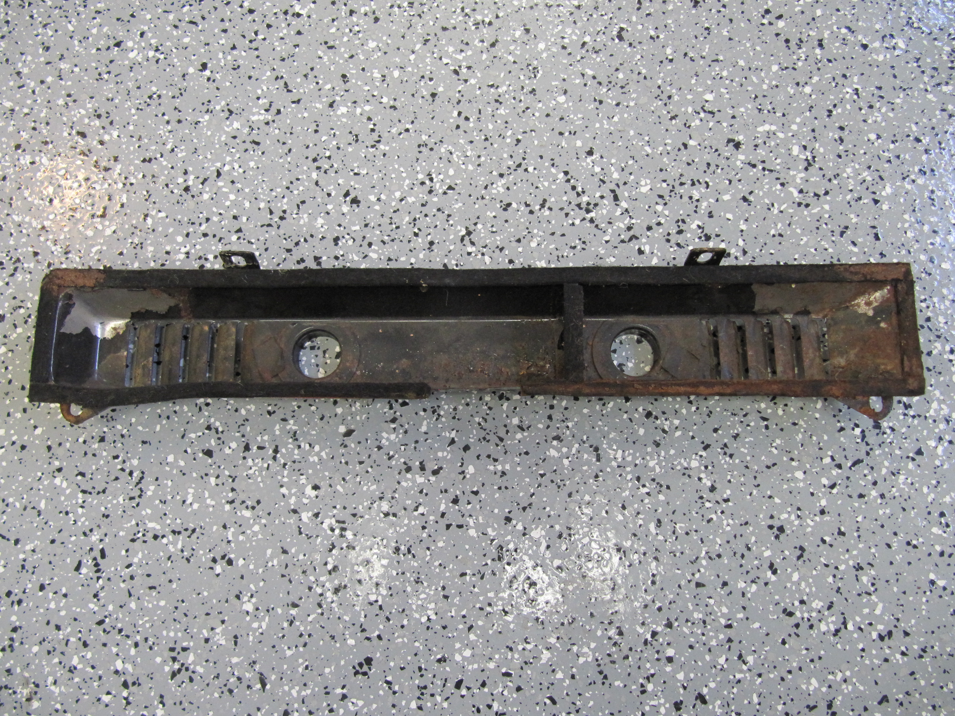
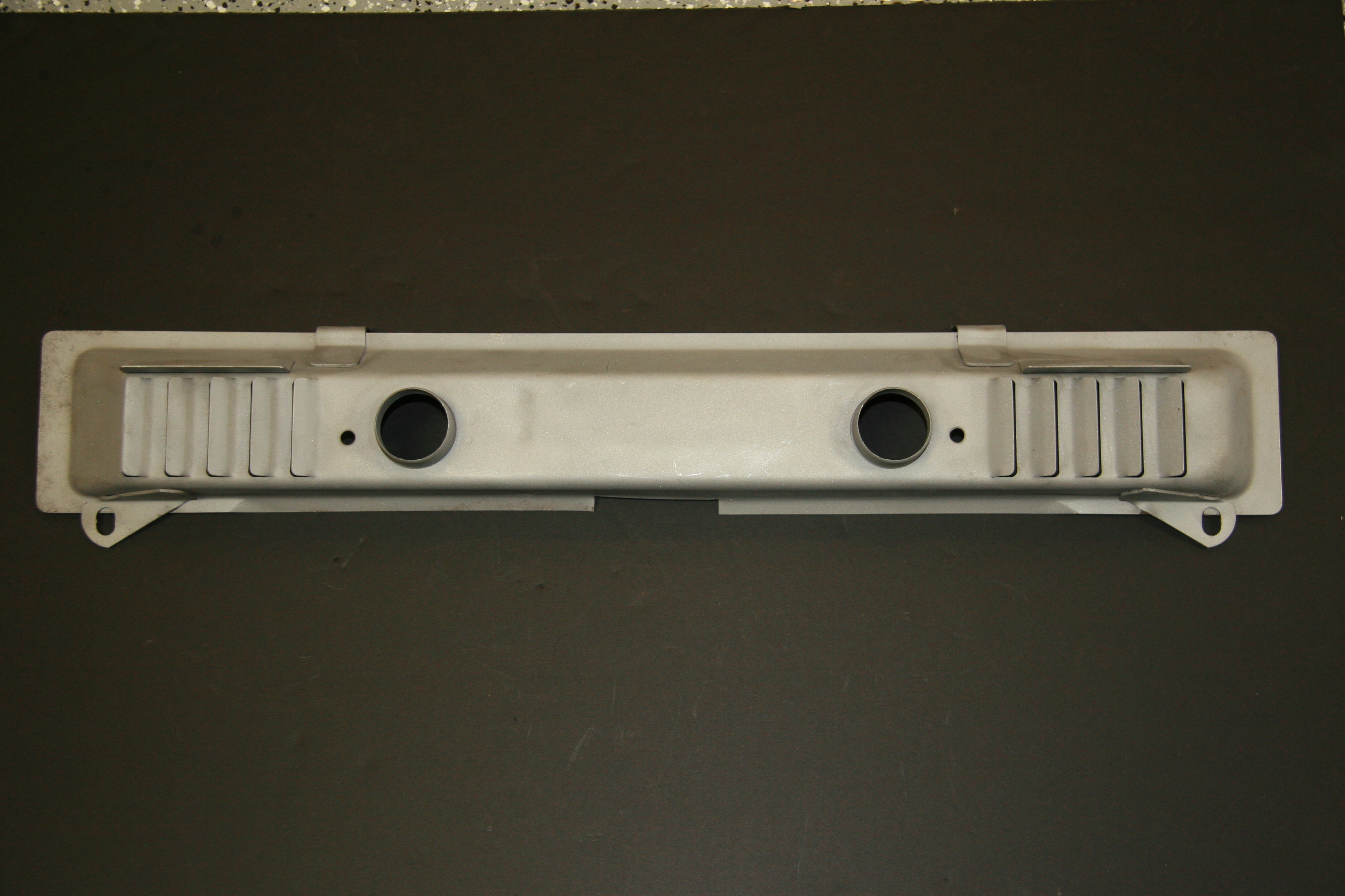
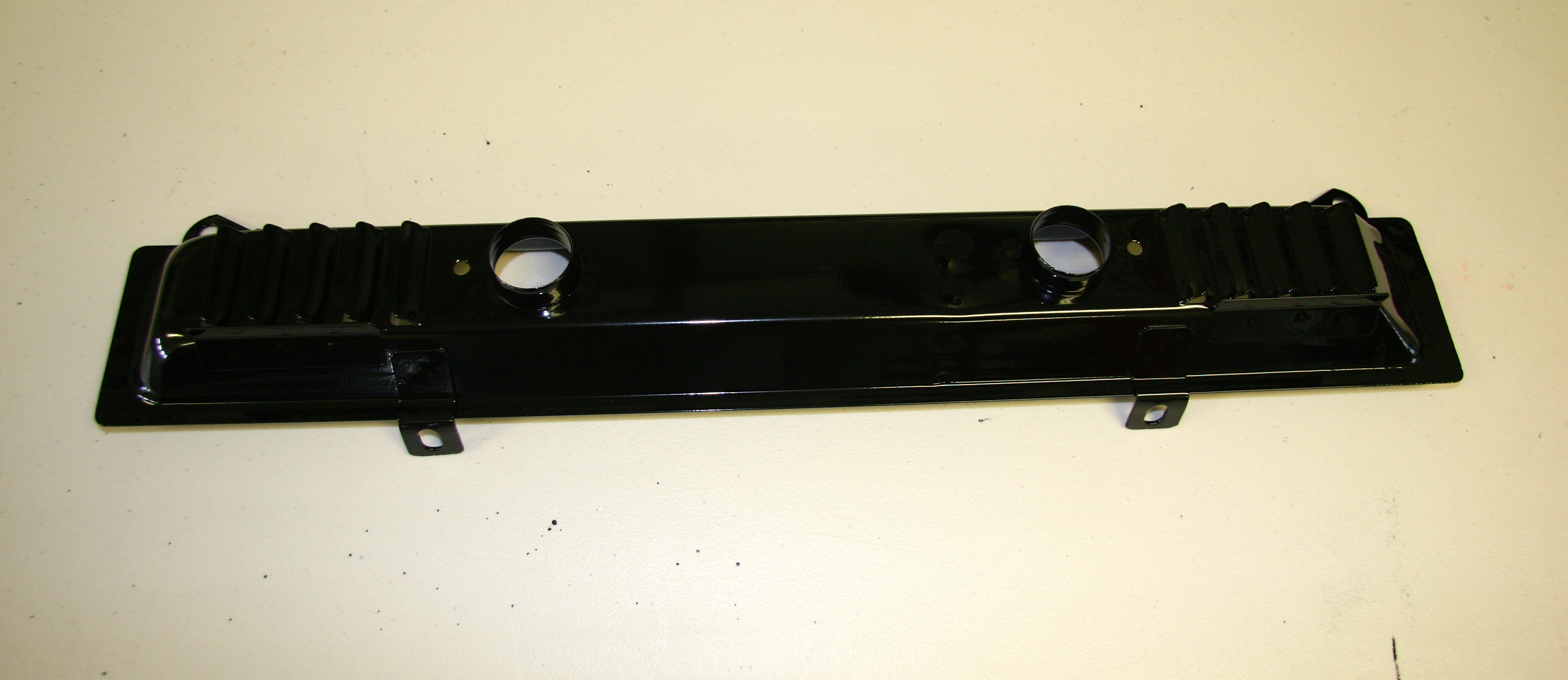
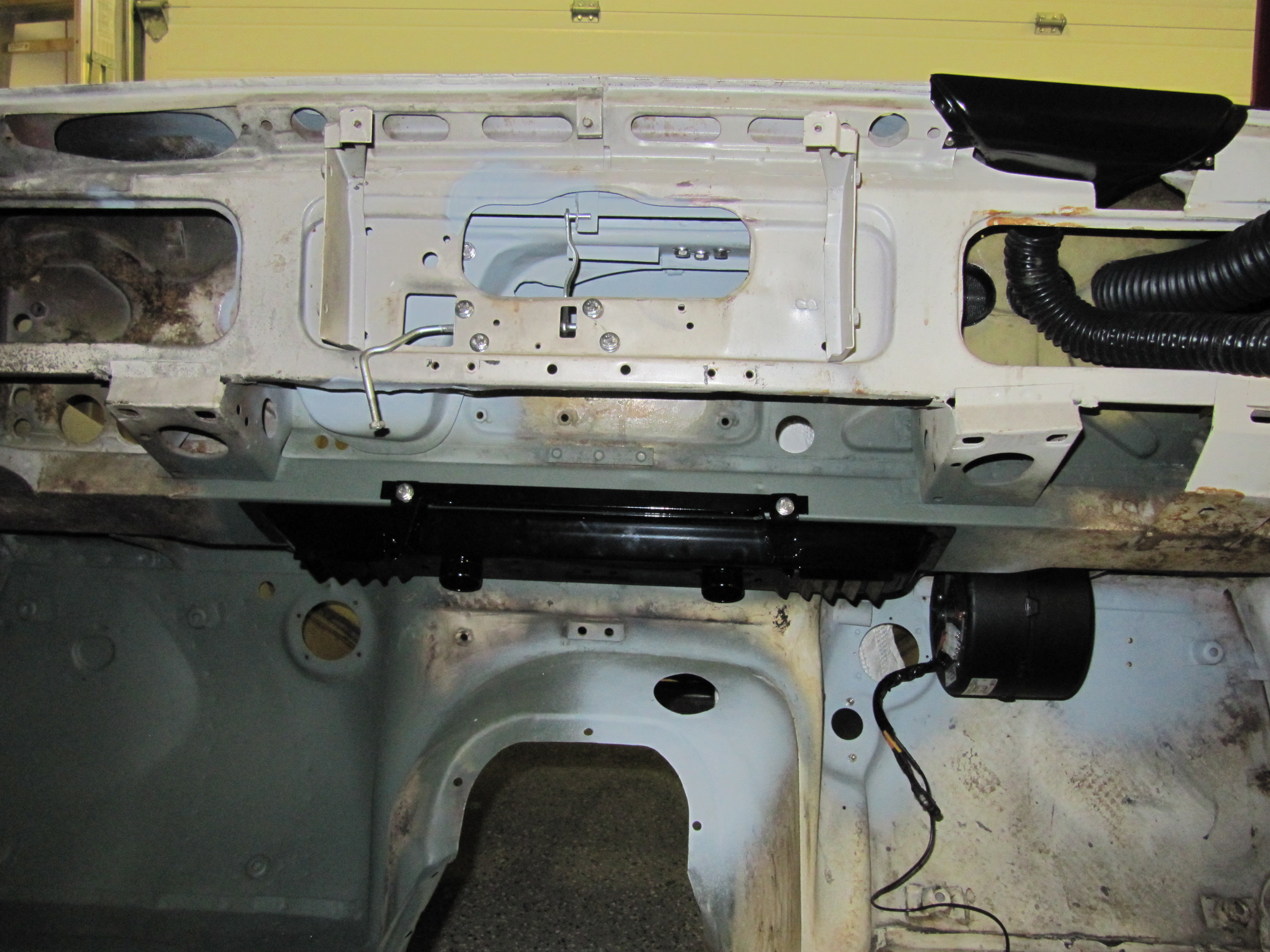
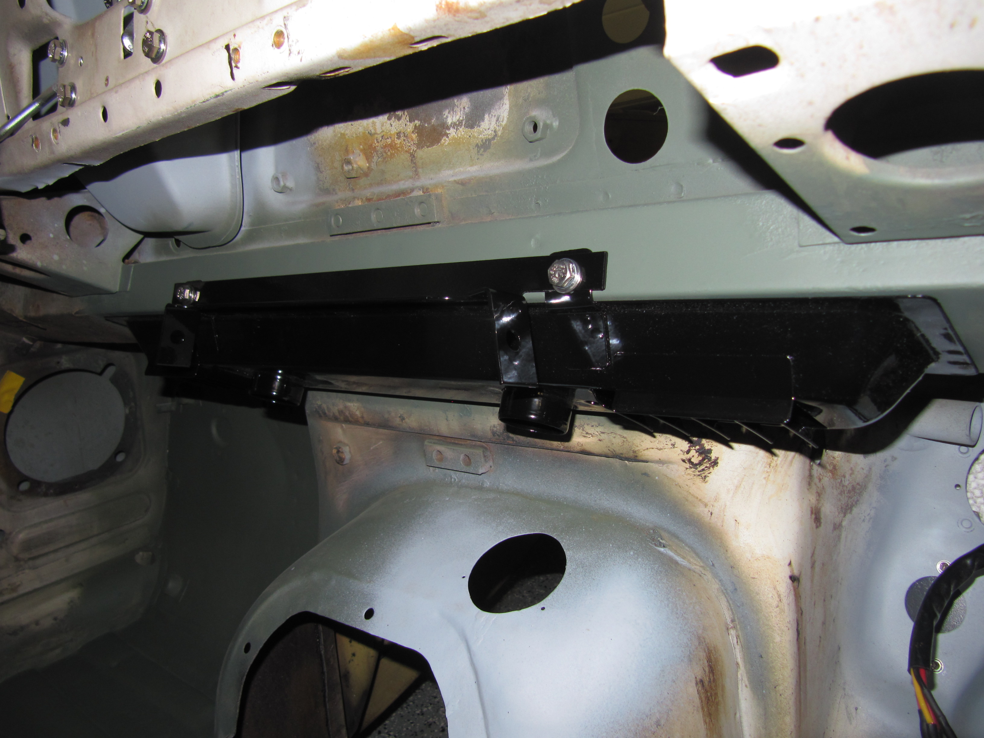
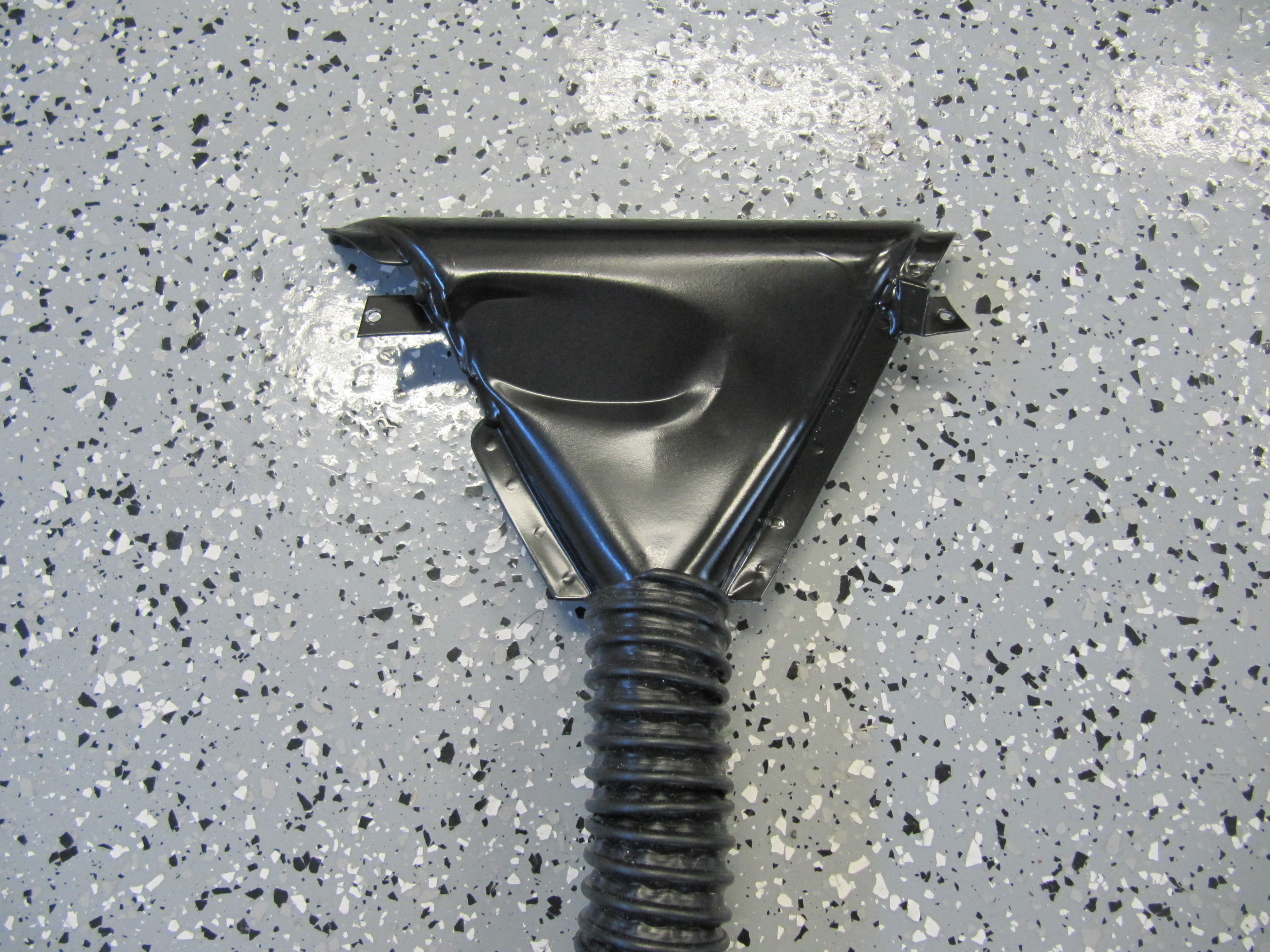
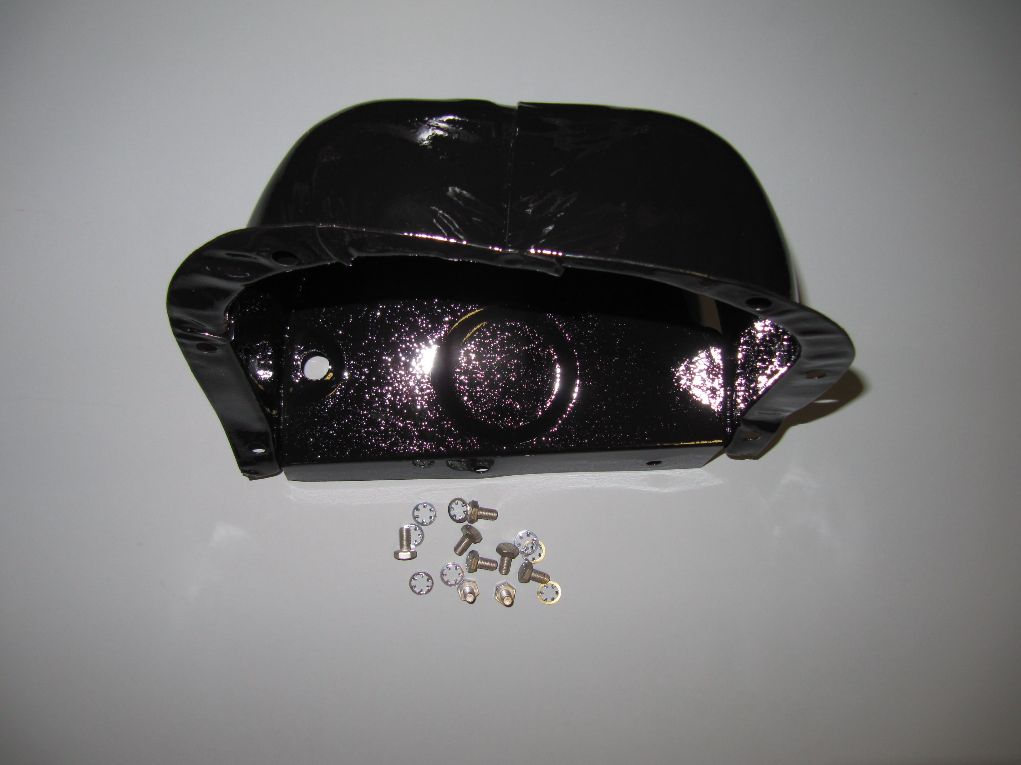
Brake Servo and Cowl
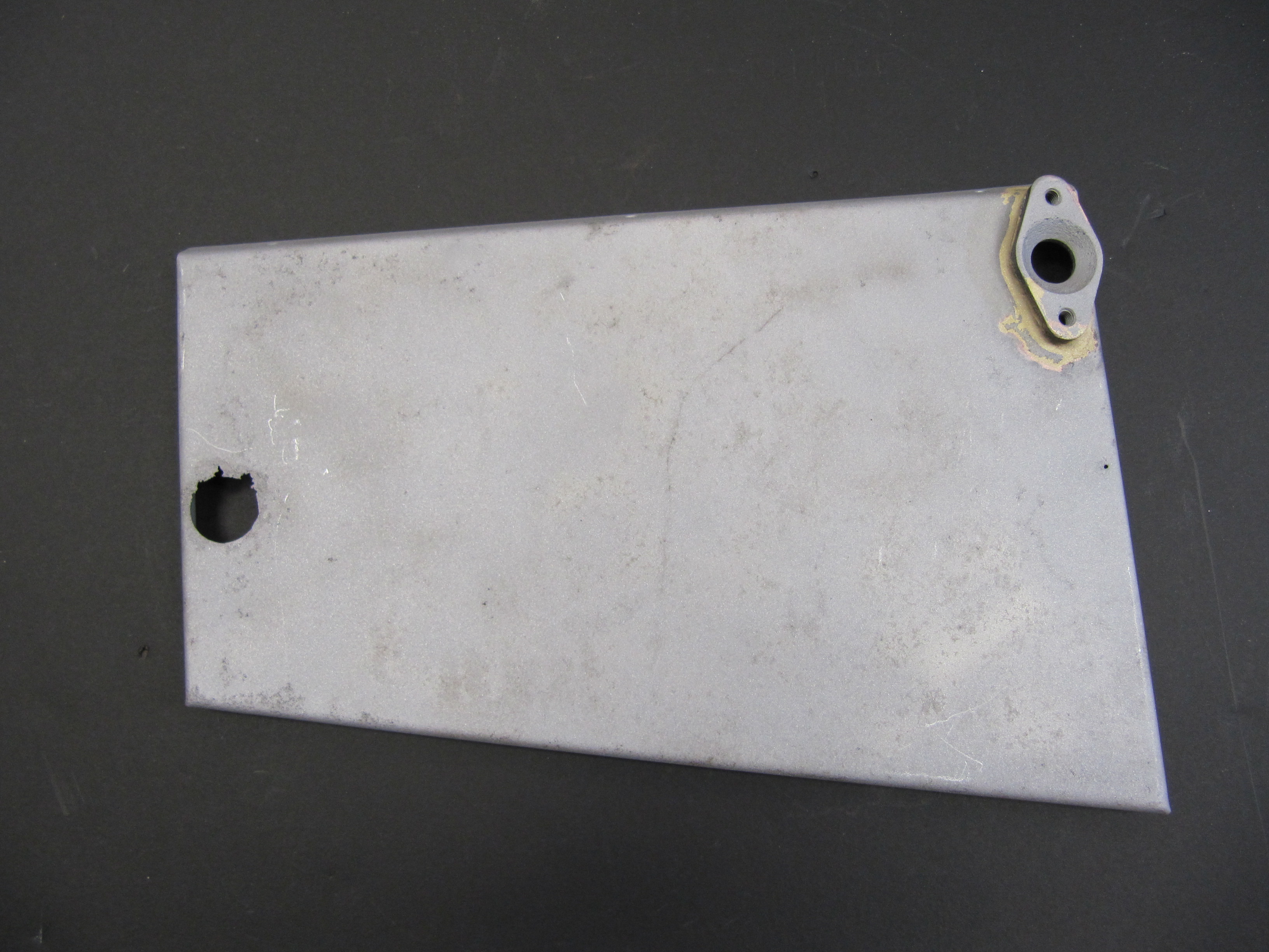
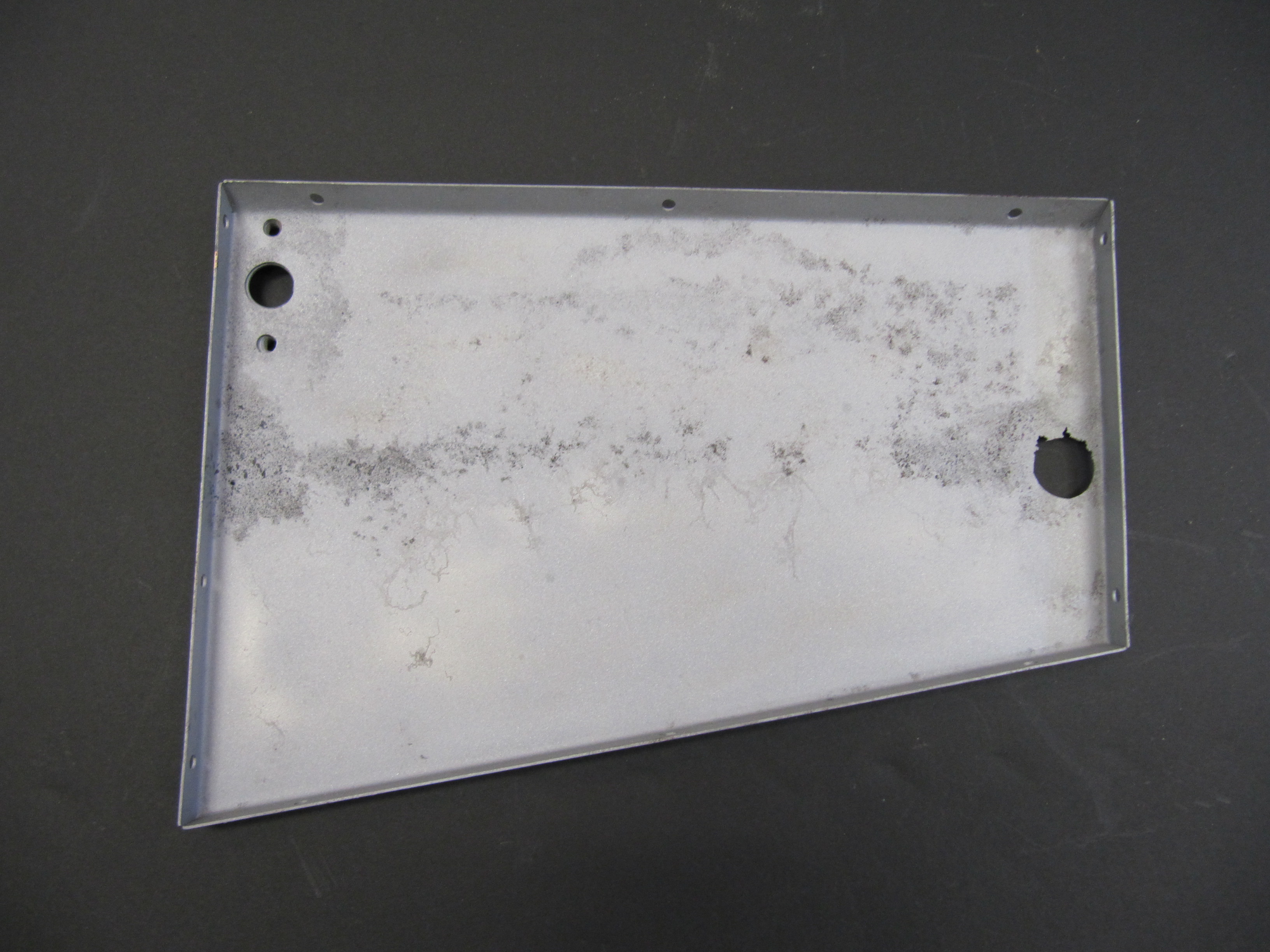
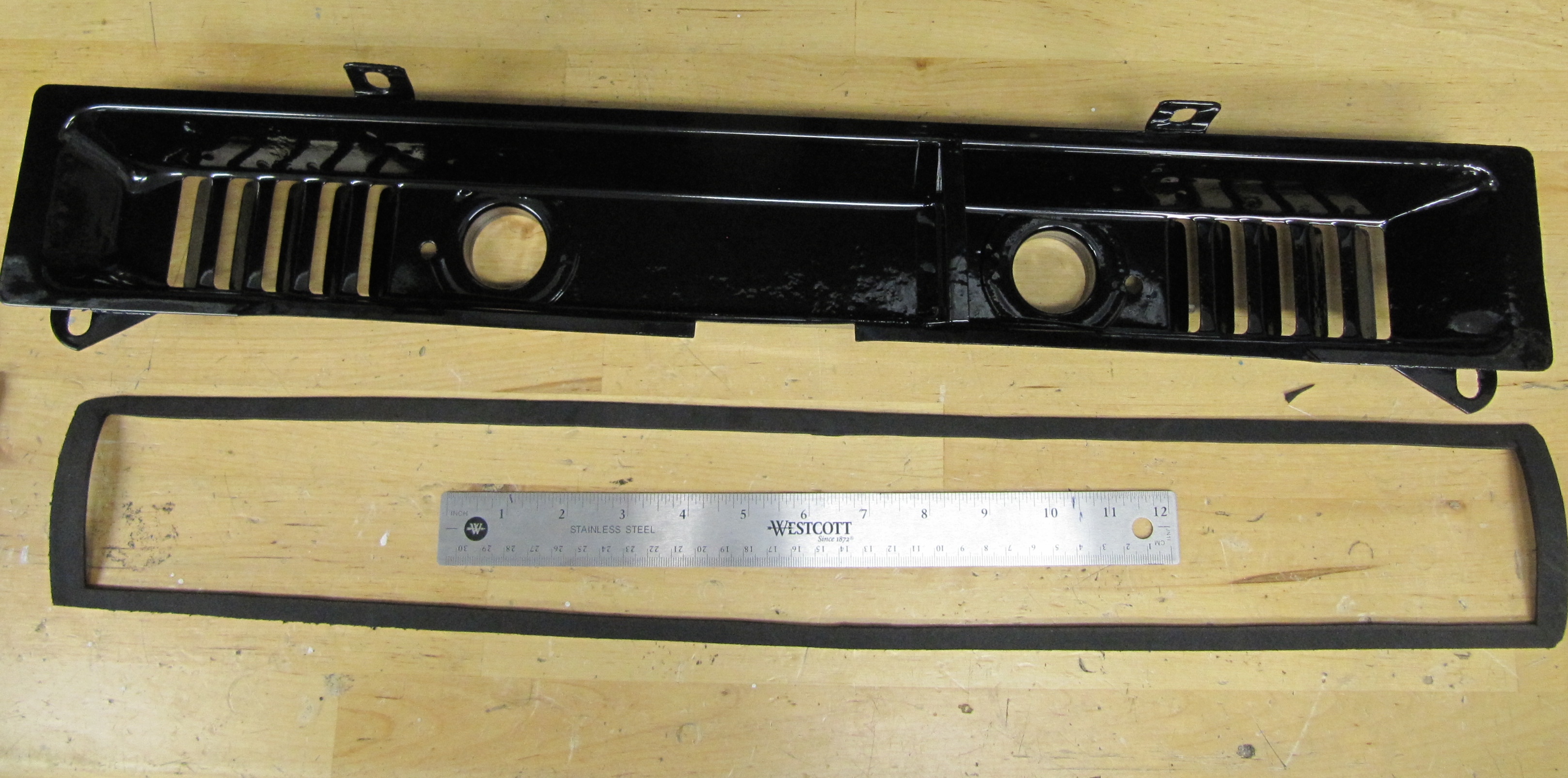
The brake servo sites in a Cowl, On The RH Wing Valance Enclosing Brake Servo Unit. I cleaned this metalwork and painted it with POR-15. The Cowl fastens to the bodywork with seven 1/4″ – 28 x 1/2″ hex head bolts with accompanying flat and shakeproof washers.
Cowl on RH Wing Valance Enclosing Brake Servo Unit
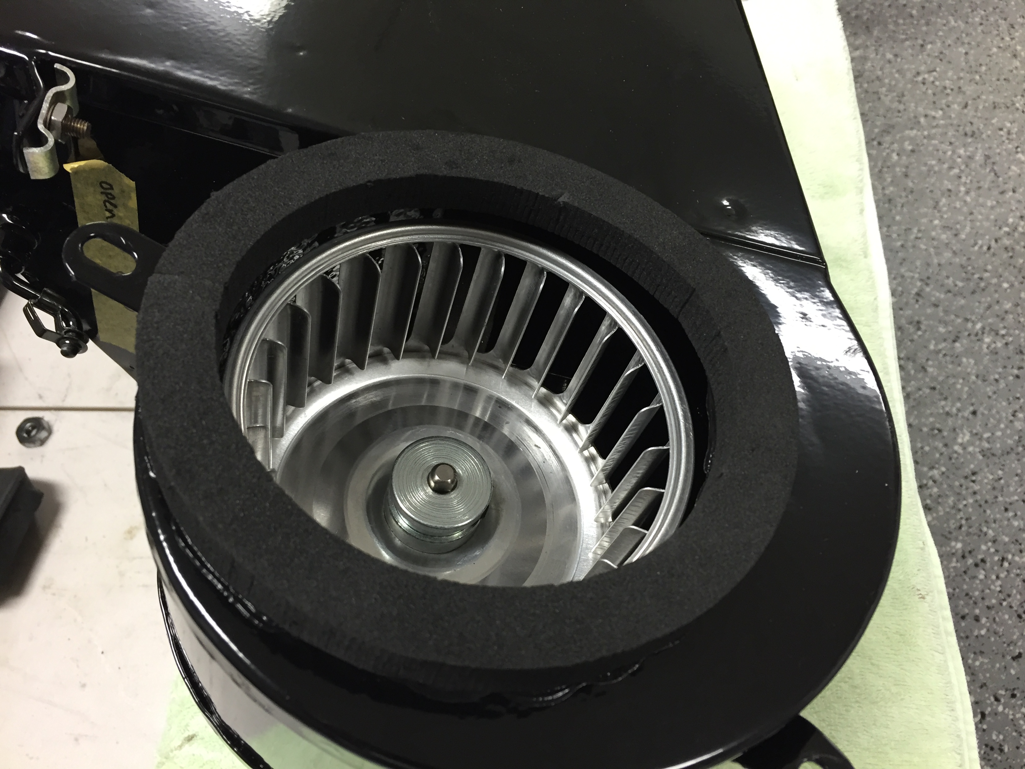
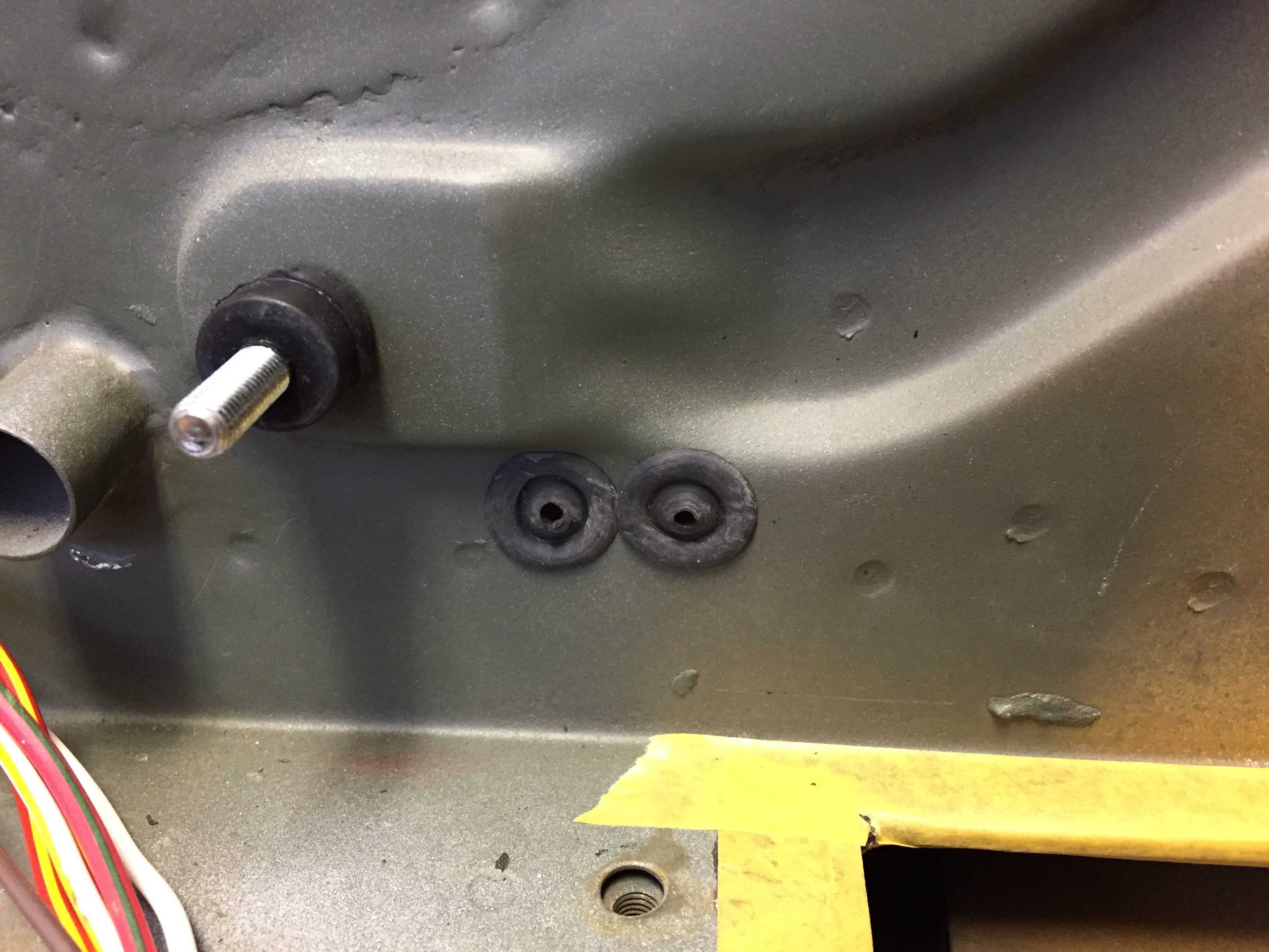
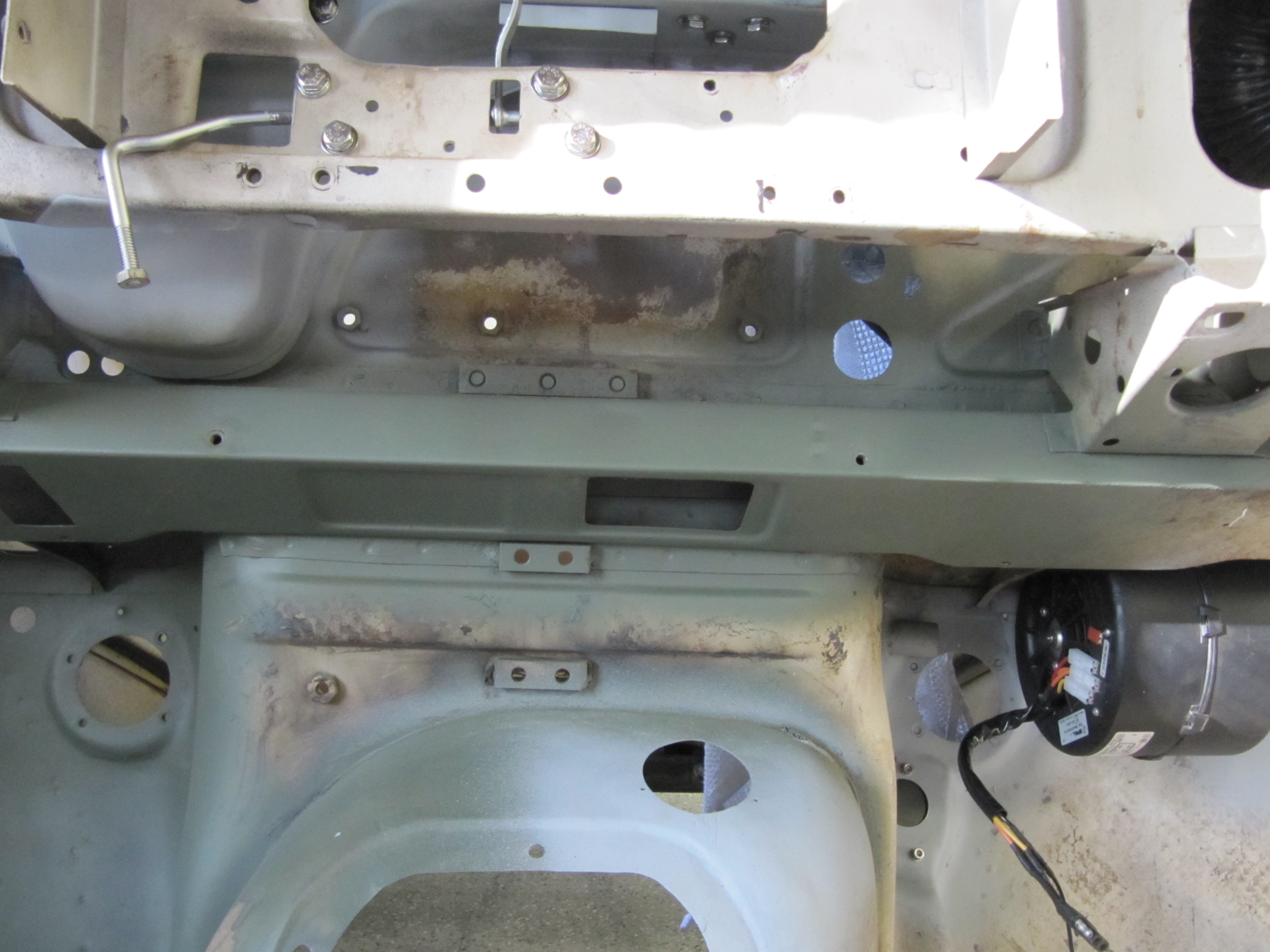
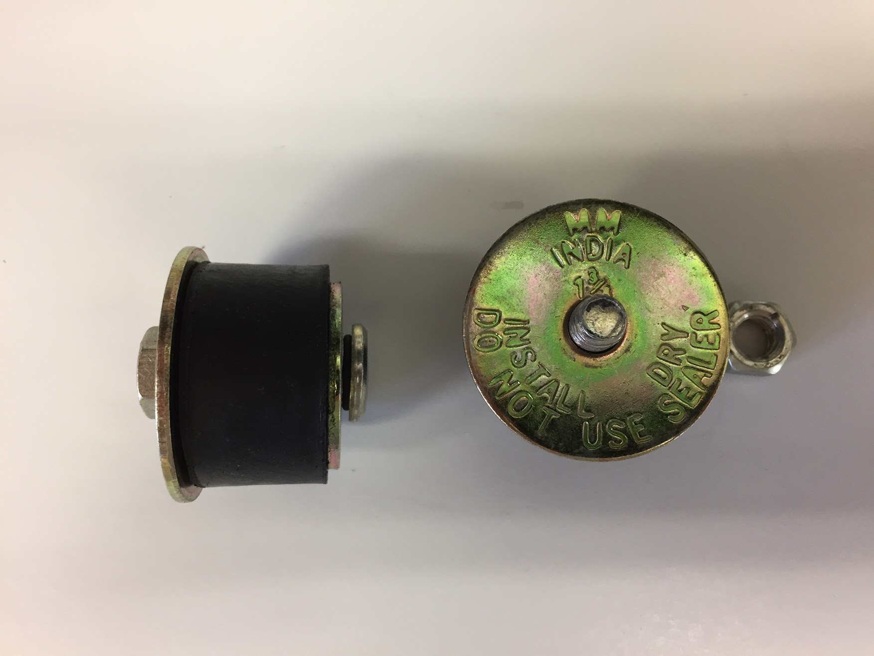
I trial fit the cowl and the Reservac with shield when building the air conditioning system. The cowl has three rubber grommets and steel spacers fitted for the studs on the servo. The steel spacers have the following dimensions: height .255″, O.D. .375″, I.D. .270″. These are secured with hex nuts and internal tooth lock washers.The servo is also supported with two studs from the Support Block and Clamp for Mounting of Servo to the Front Wing Valance referenced above.
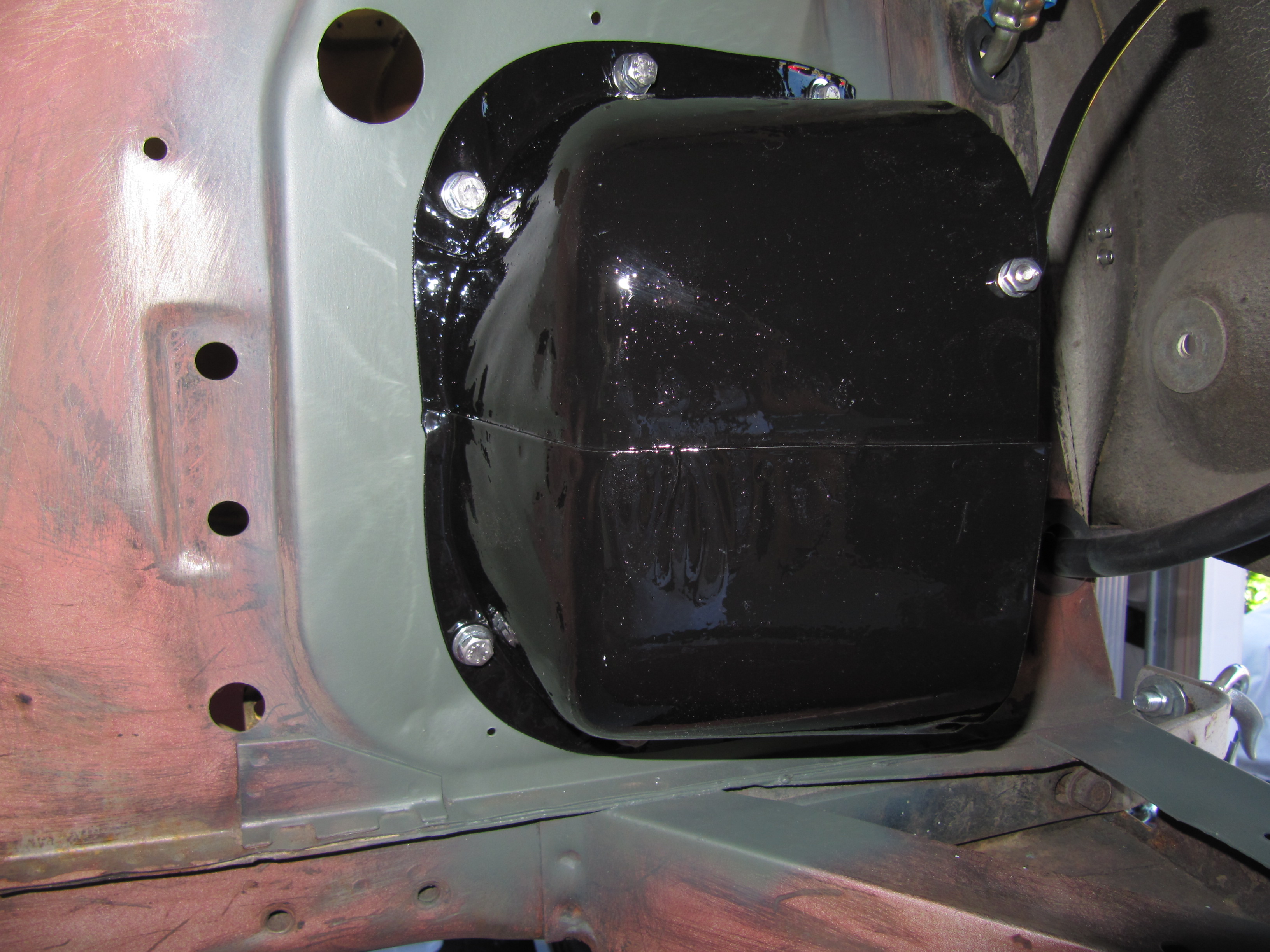
Brake Booster Cowl Mounted
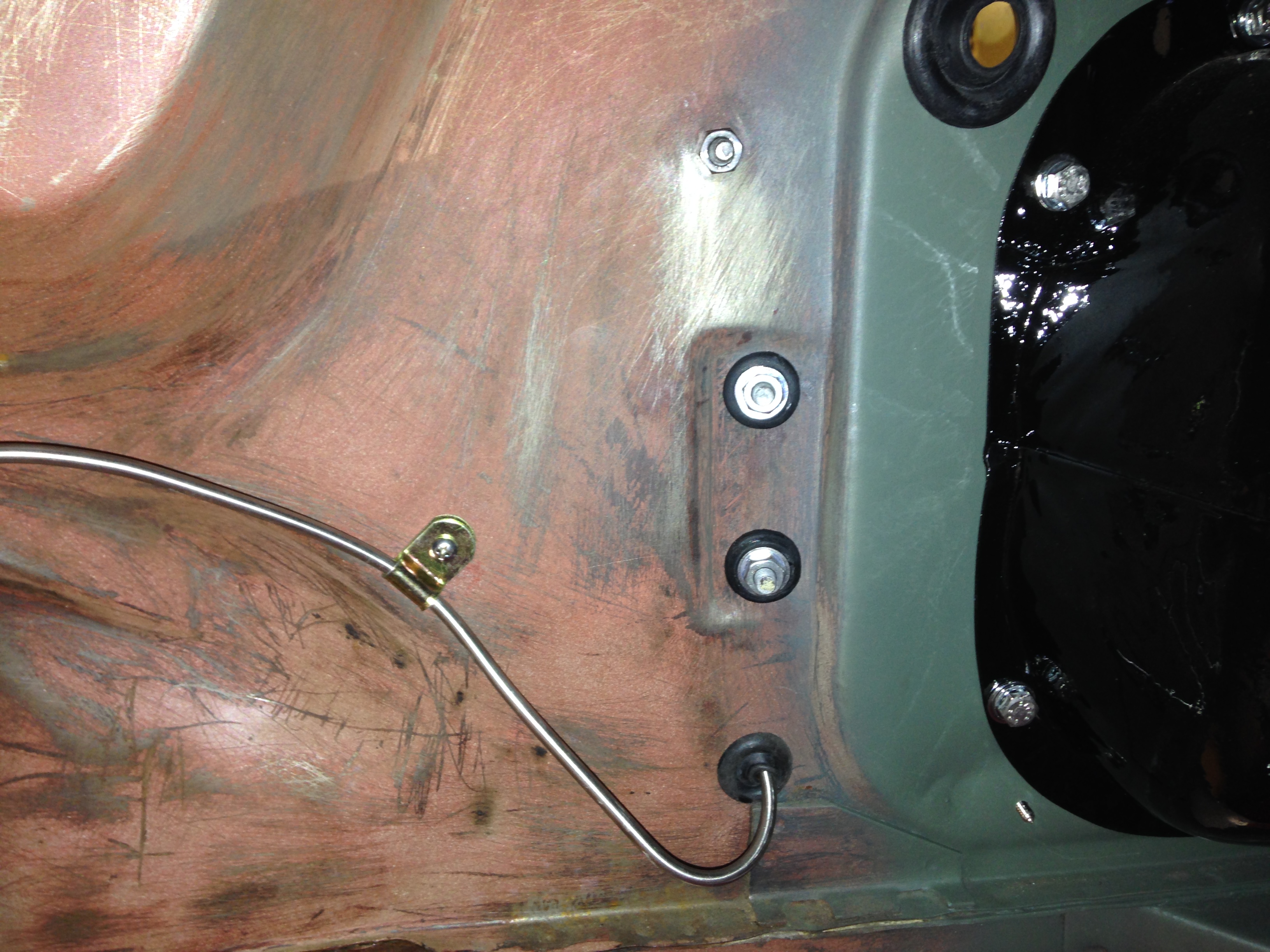
Brake Servo RH Valance Grommets and Steel Spacers

Brake Booster Cowl Mounted

Brake Servo Installed in Cowl with Breather Hoses
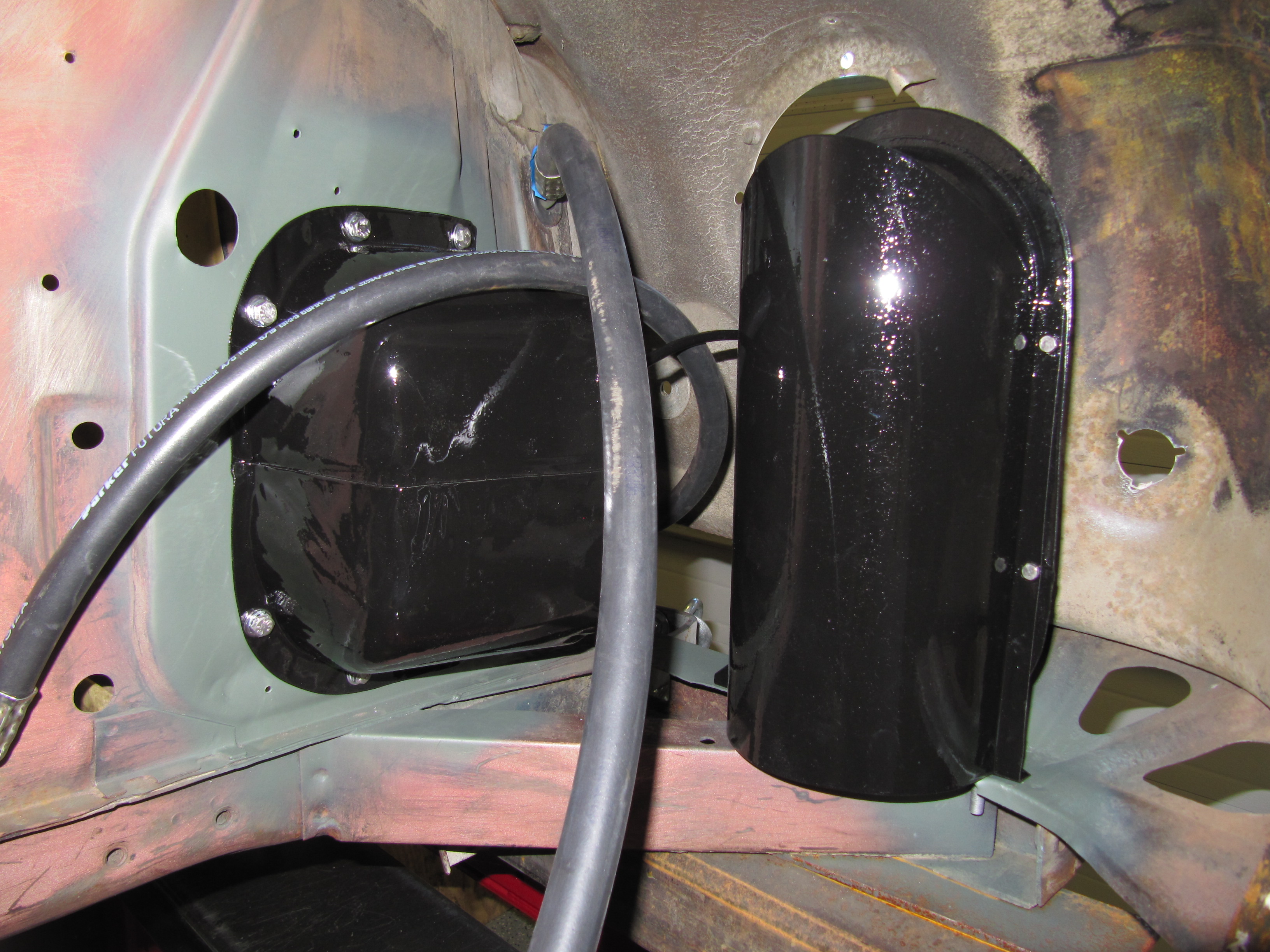
Brake Booster Cowl and Vacuum Tank Mounted
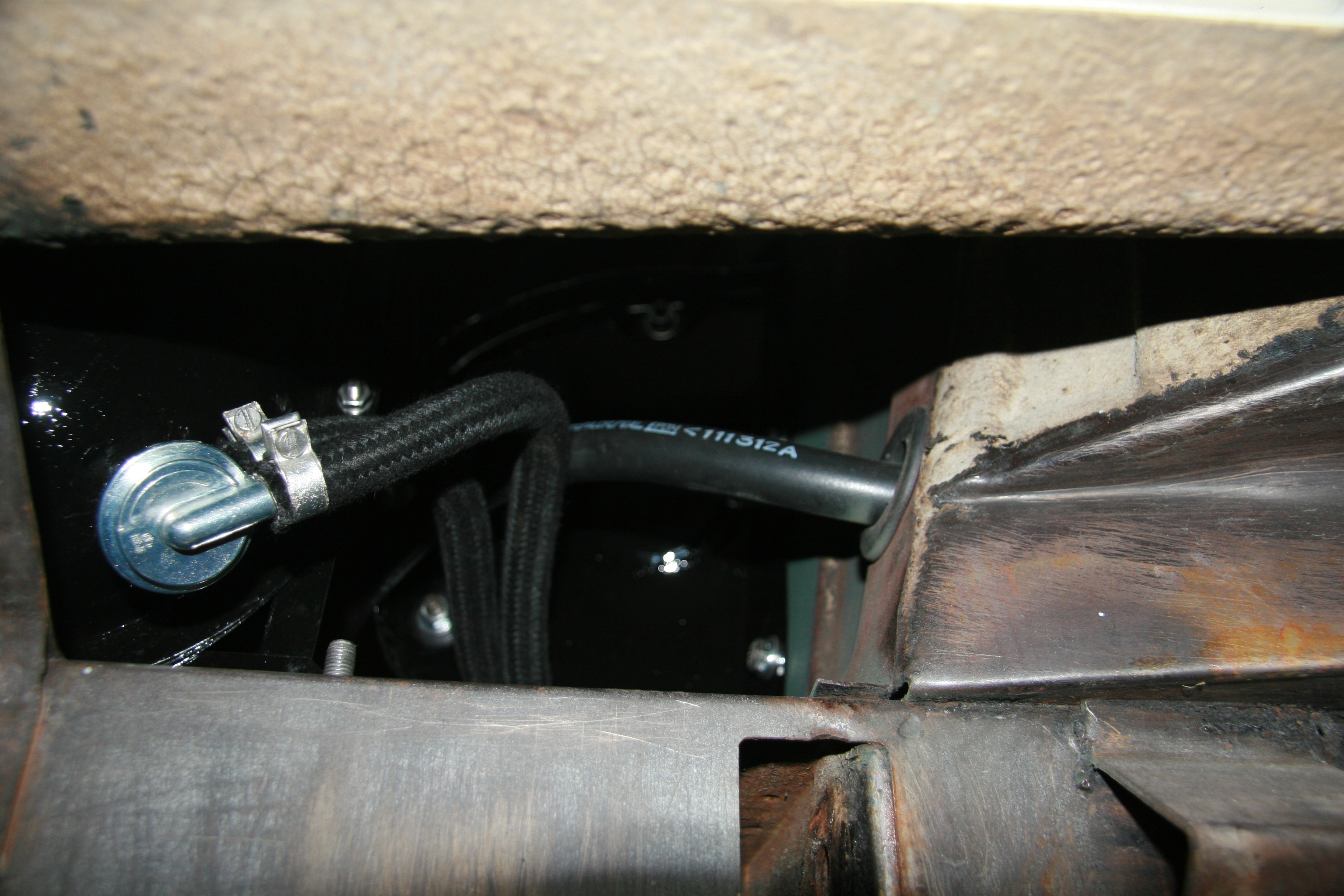
Check Valve and Breather Hose
Brake Servo Mounted

Brake Servo Mounted
Brake Hydraulic Lines at Servo
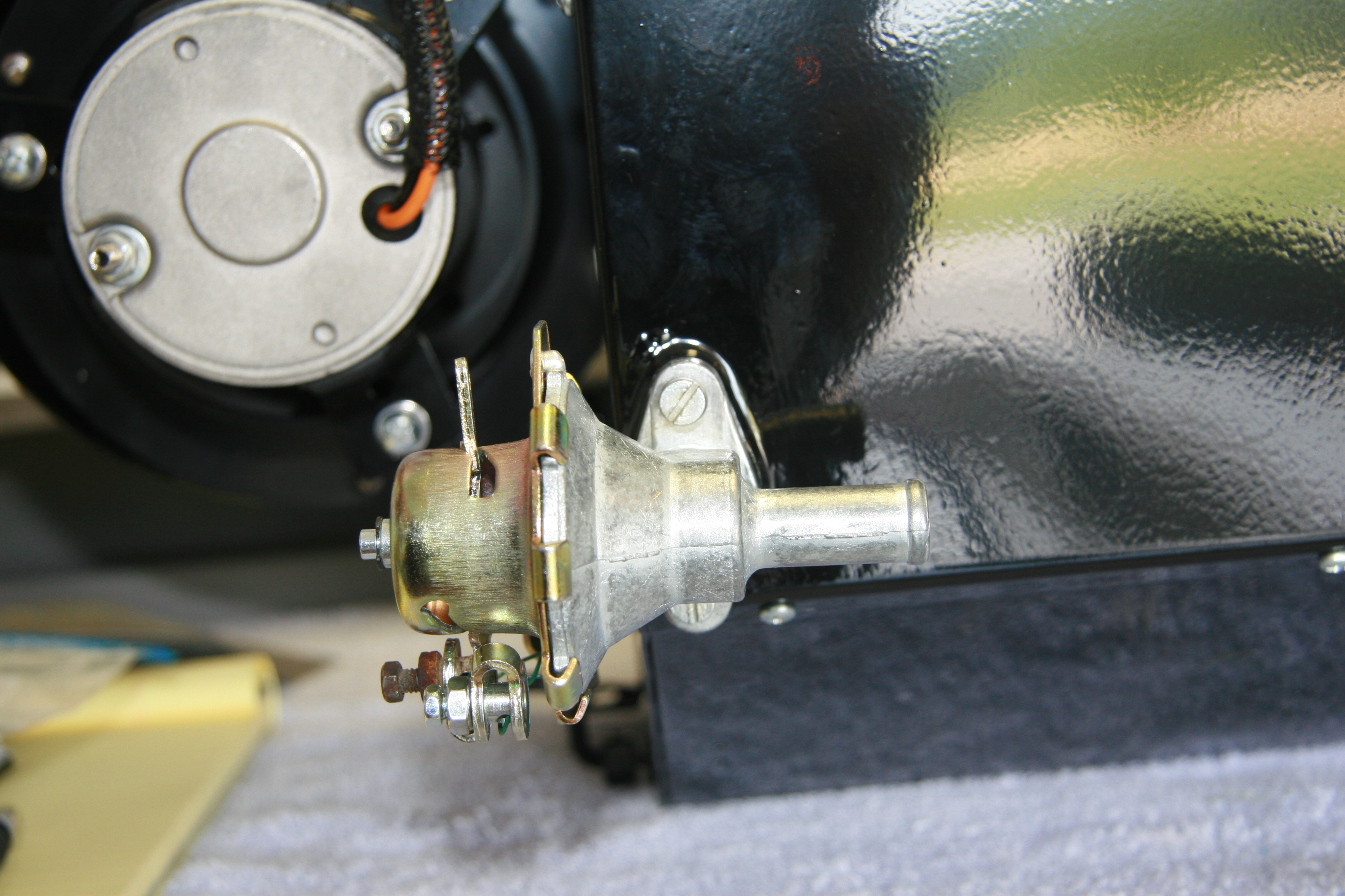
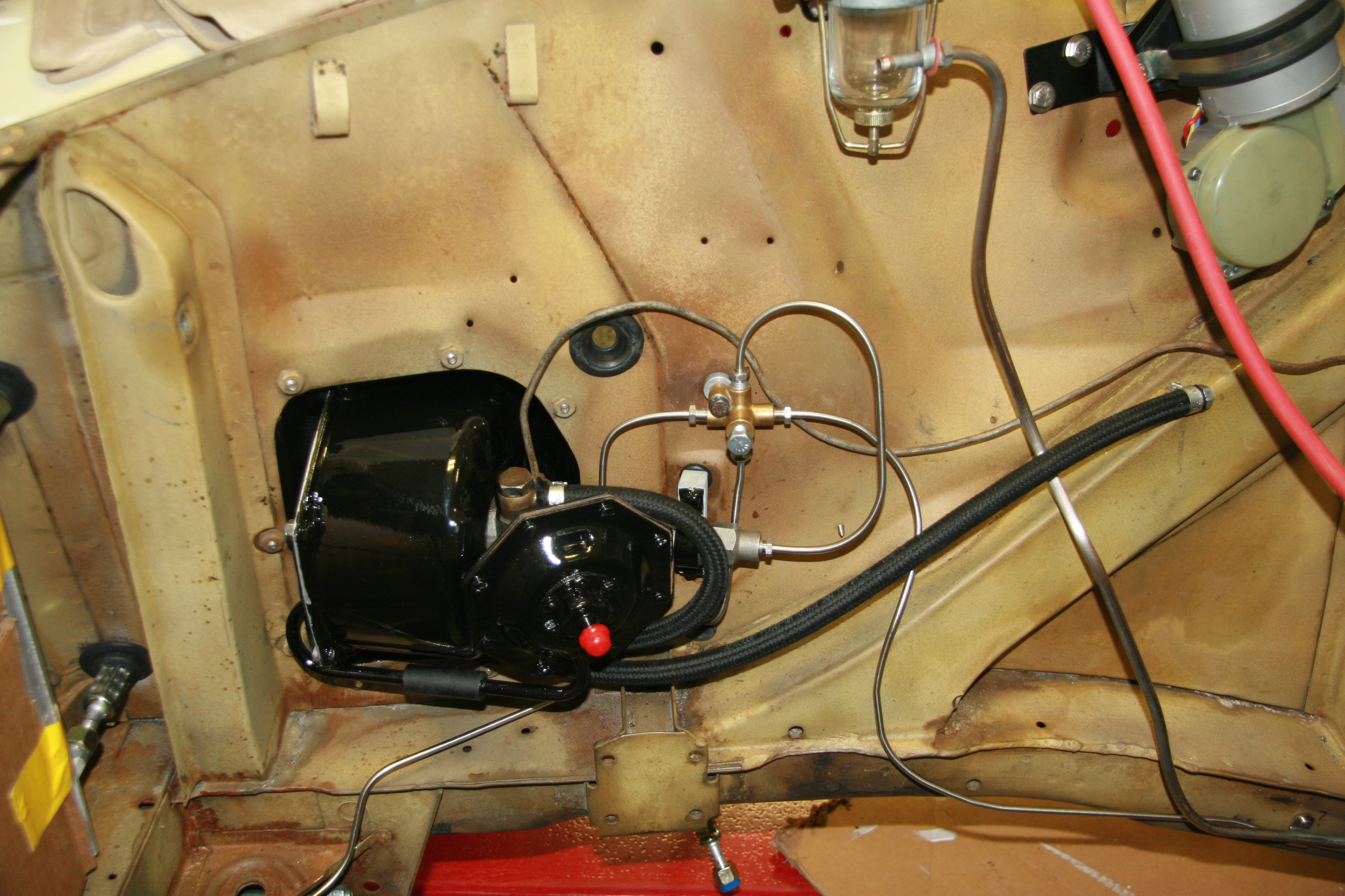
The air cleaner will need to be secured to the radiator shroud after it is installed. The bracket has been refurbished and painted with new fasteners and a restored air cleaner is pushed onto the new rubber hose.
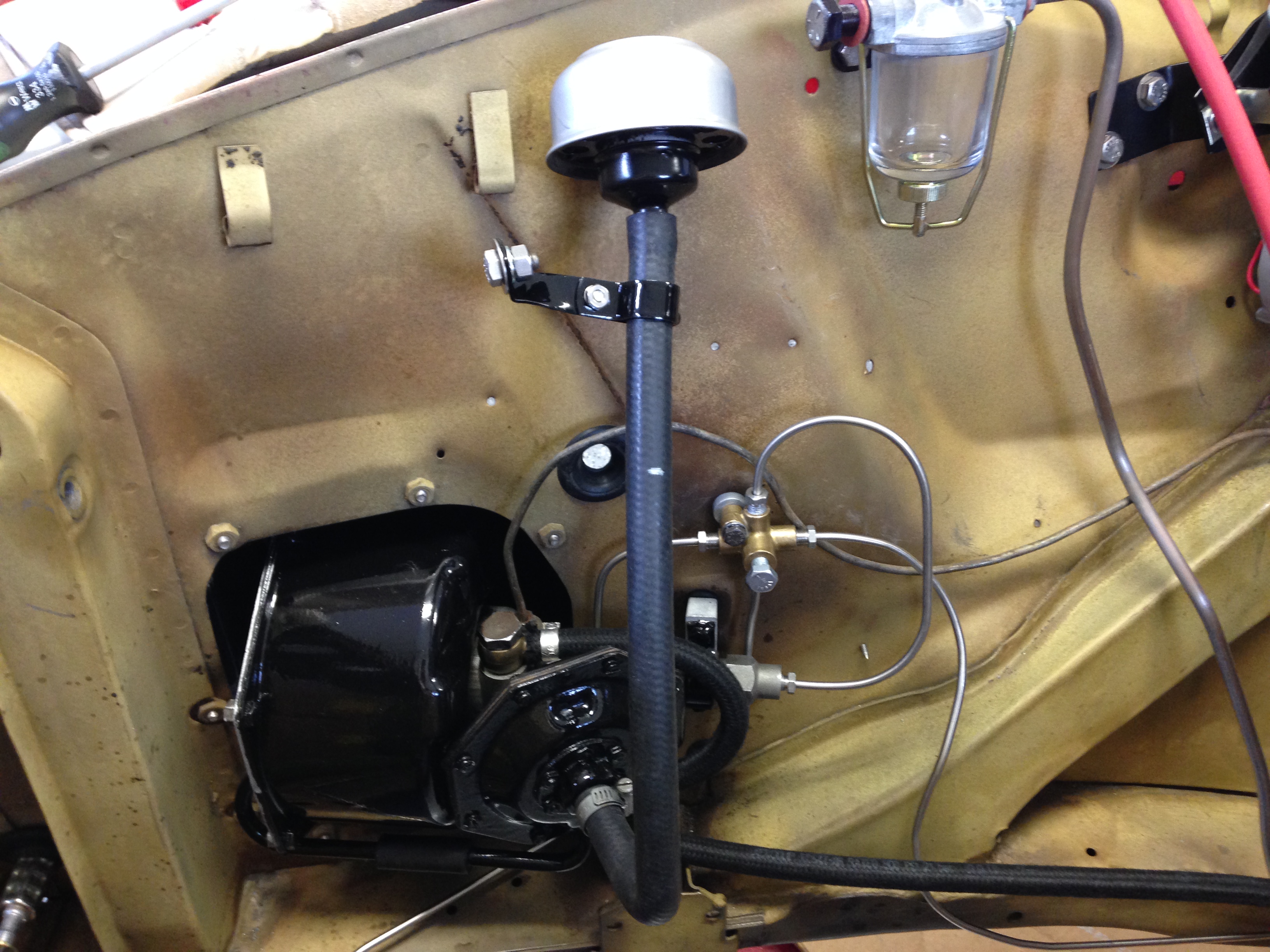
Brake Servo Breather Pipe and Air Cleaner
These are a few images of the Brake Vacuum Servo Air Cleaner and Hose installed after the engine and radiator are fitted.
Air Cleaner Hose for Brake Vacuum Servo Hose Installed
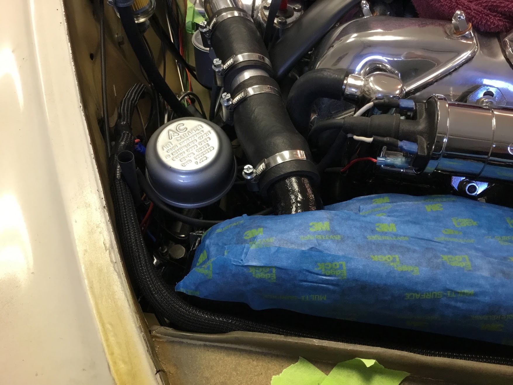
Air Cleaner for Brake Vaccum Servo installed
I thought the original support bracket mounted to the upper right stud on the radiator (shroud) held the air cleaner too close to other items that would cause rubbing so I used a 3/4″ threaded extender to move the air cleaner slightly rearward.
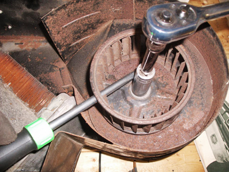
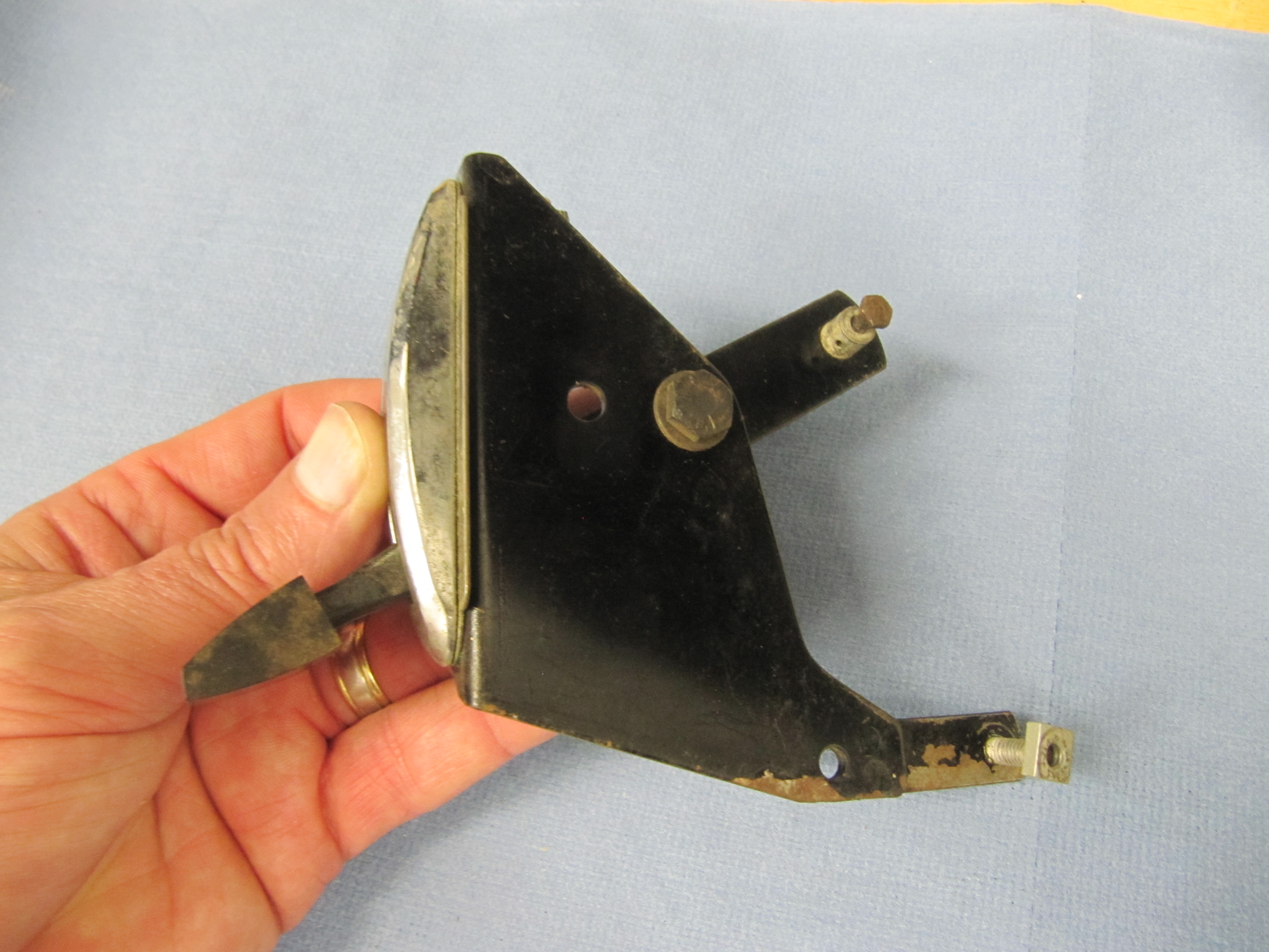
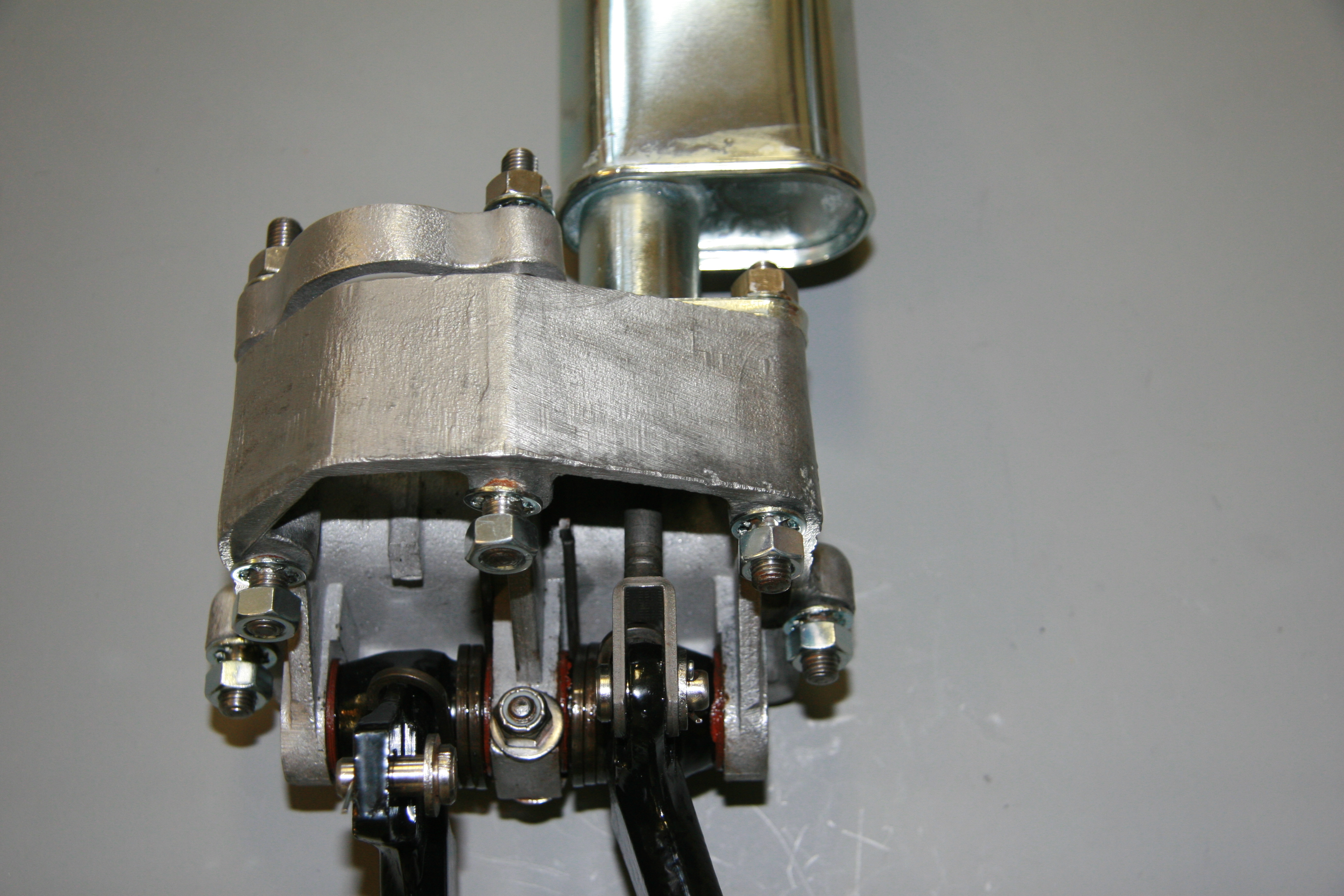
Brake Pedal and Master Cylinder
I previously removed the brake and clutch housing complete with master cylinders and pedals. To refurbish this unit, I began with disassembly of the brake components. I first separated the Girling 875 Master Cylinder from the housing. An aluminum spacer is sandwiched between the master cylinder and the housing, and held in place by two 5/16″ hex nuts and shakeproof washers on 5/16″ – 24 studs. The 5/16″ x 3/4″ clevis pin with flat washer is removed from the pedal freeing the push rod for removal.
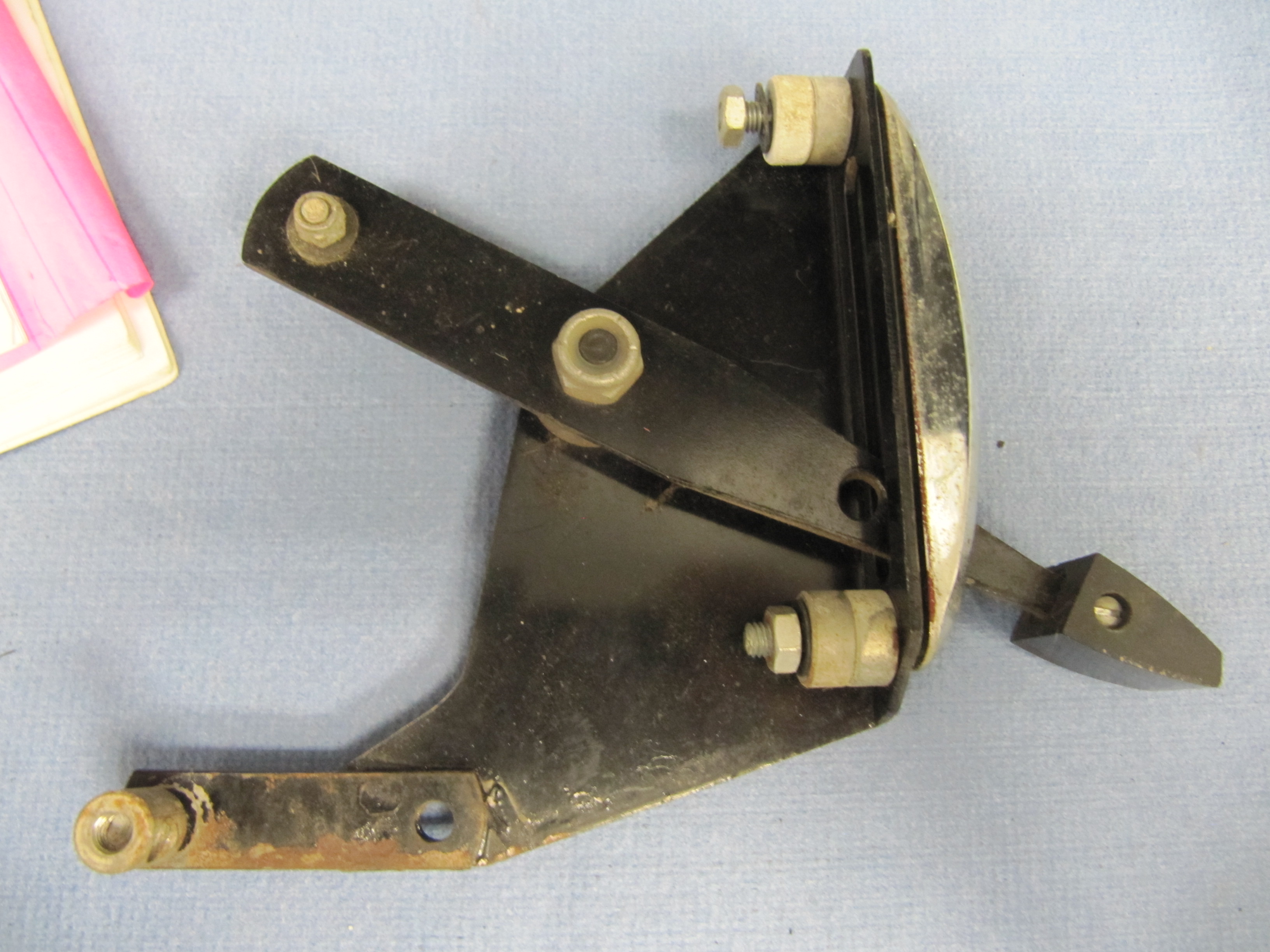
Pedal Assembly
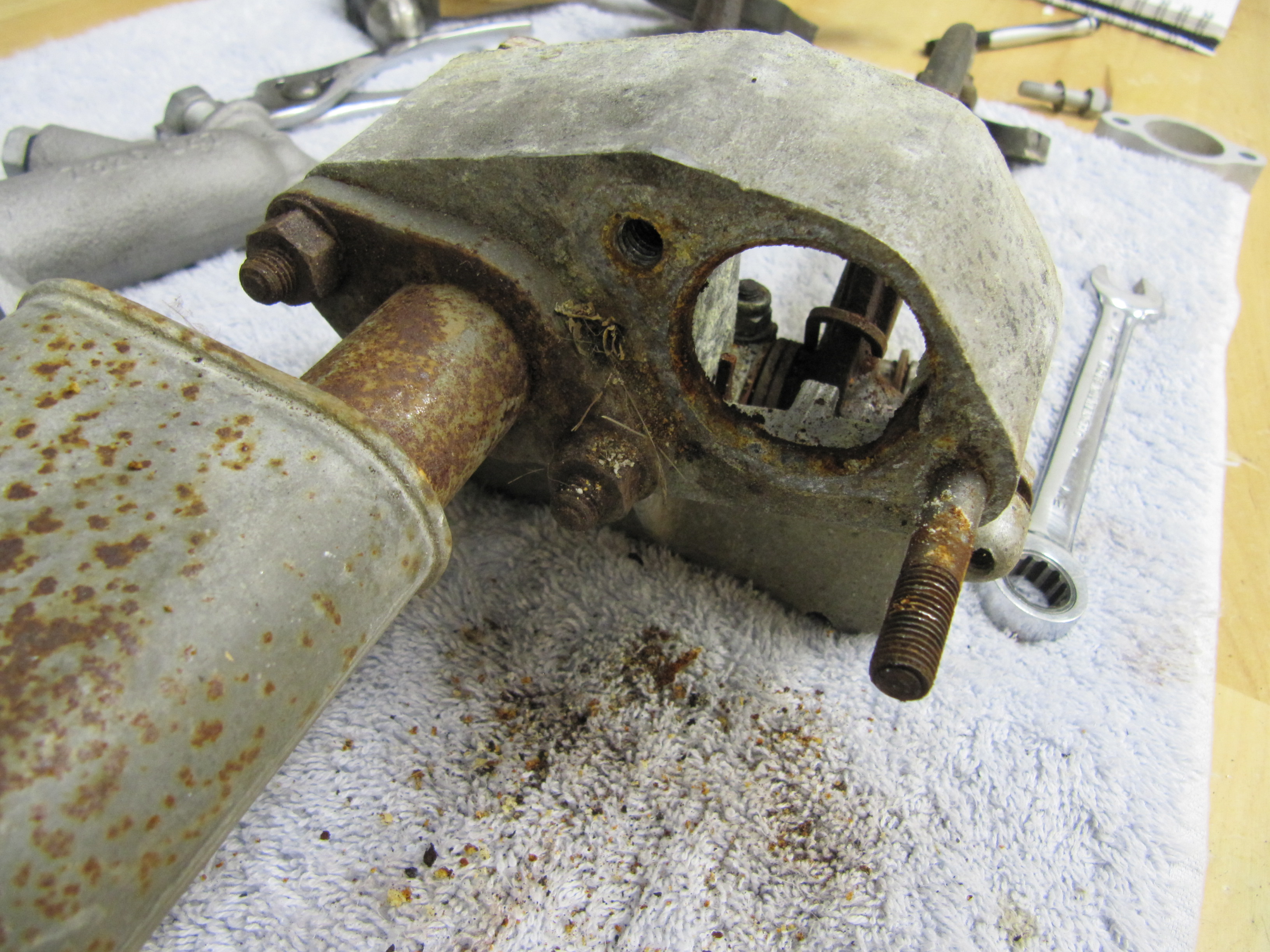
Master Removed
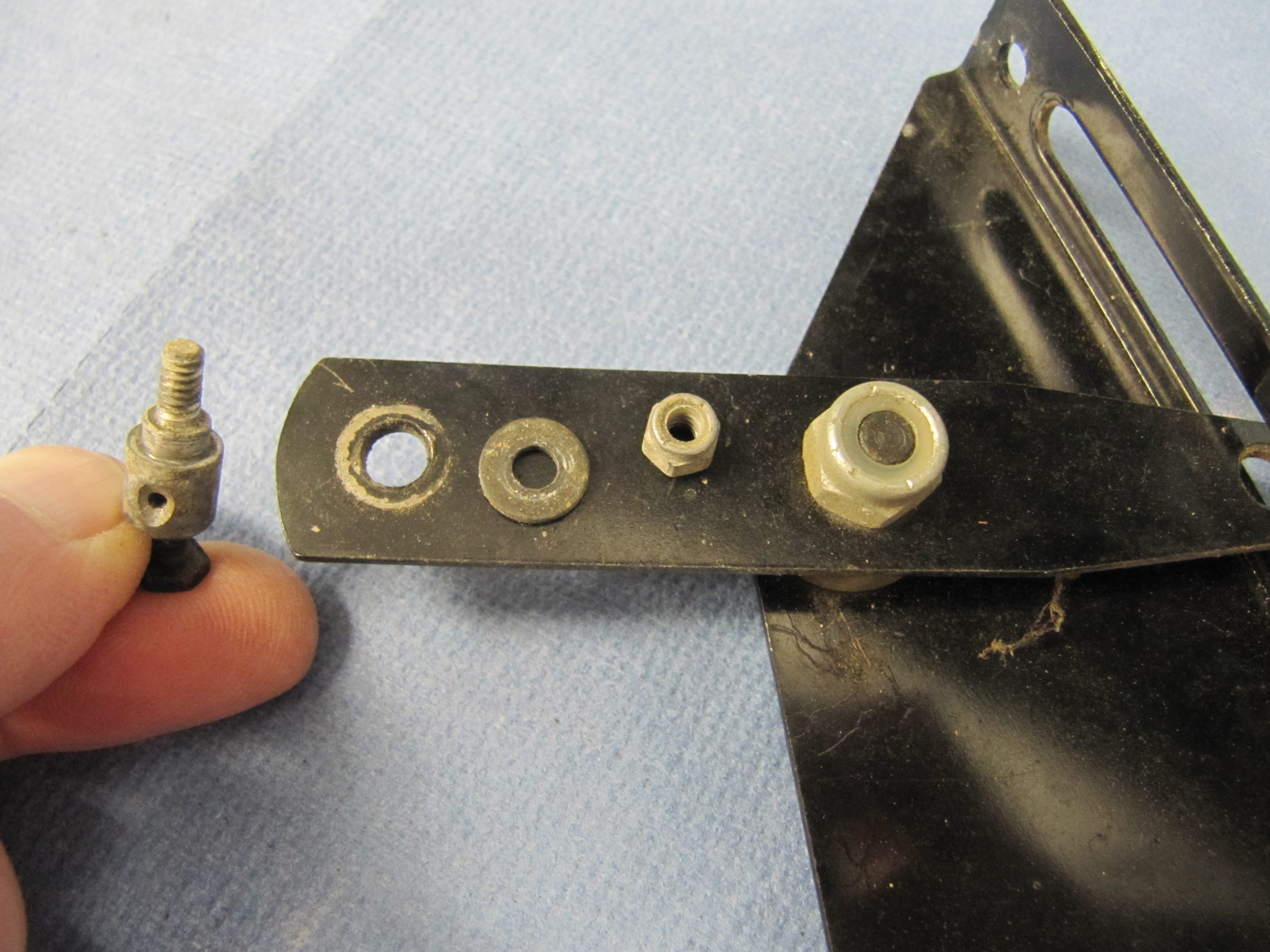
The Girling 875 Master Cylinder has a 7/8″ bore. The master was sleeved with stainless steal and a rebuild kit with new seals was installed.
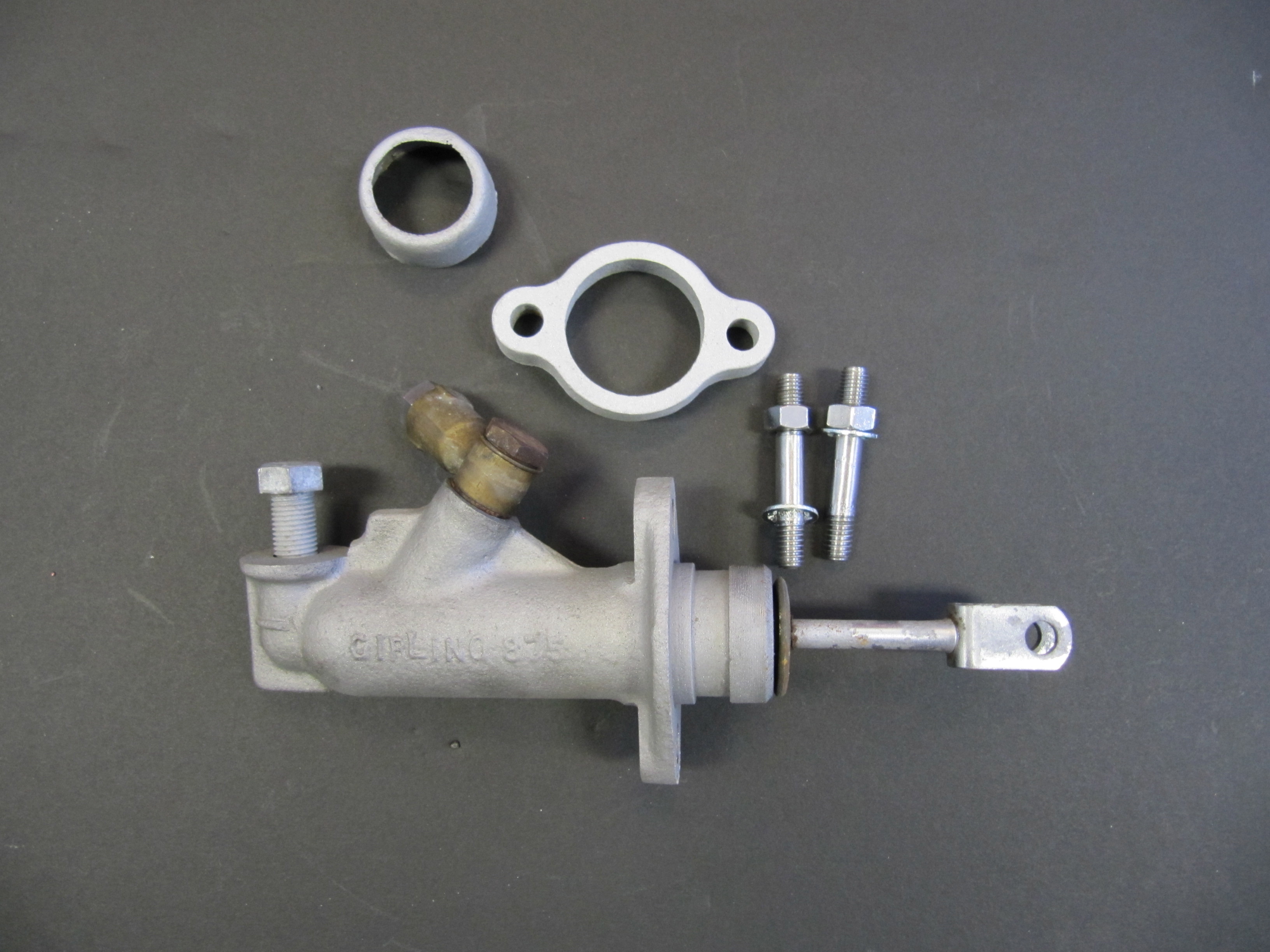
Master components
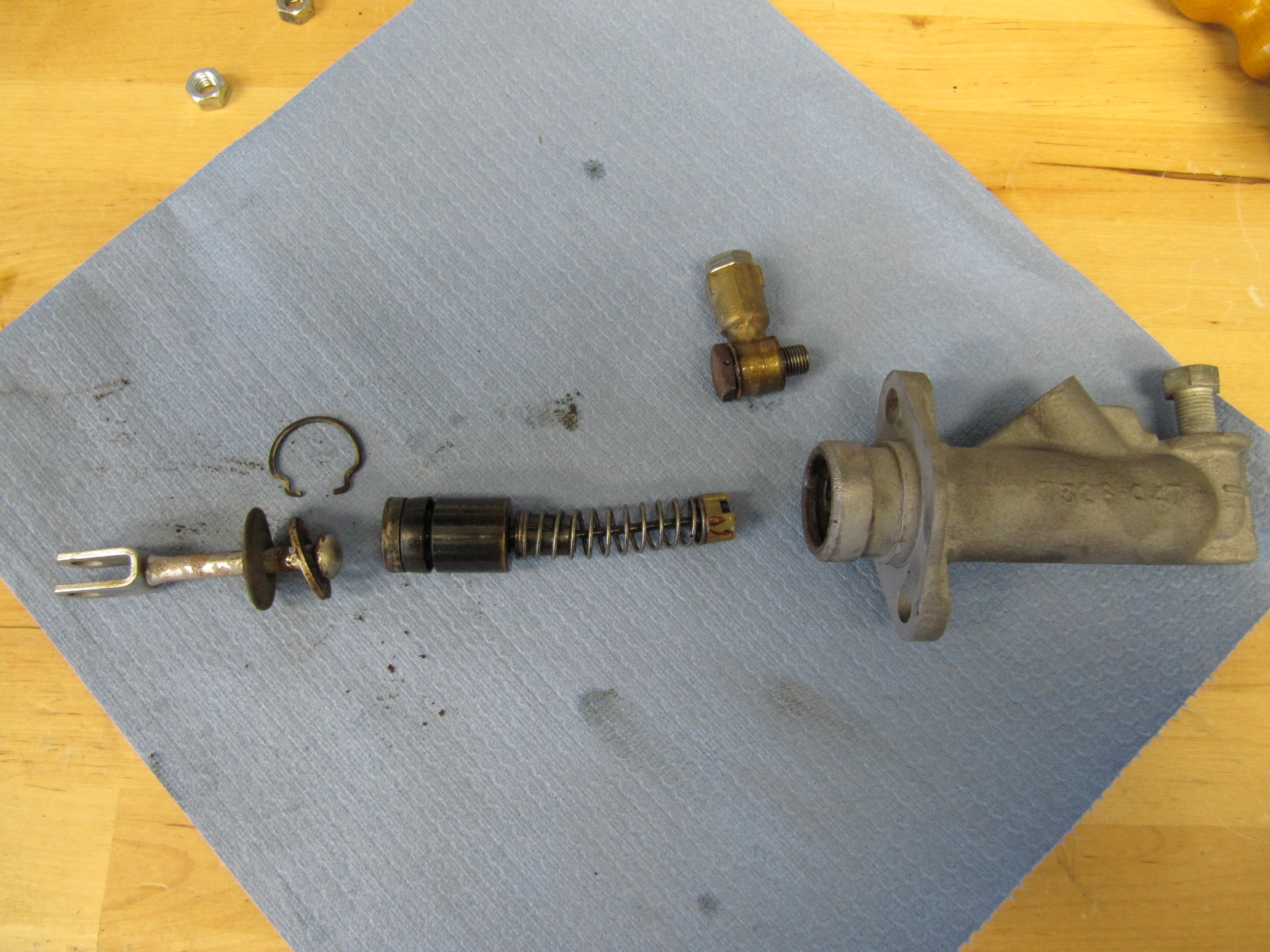
Master Components
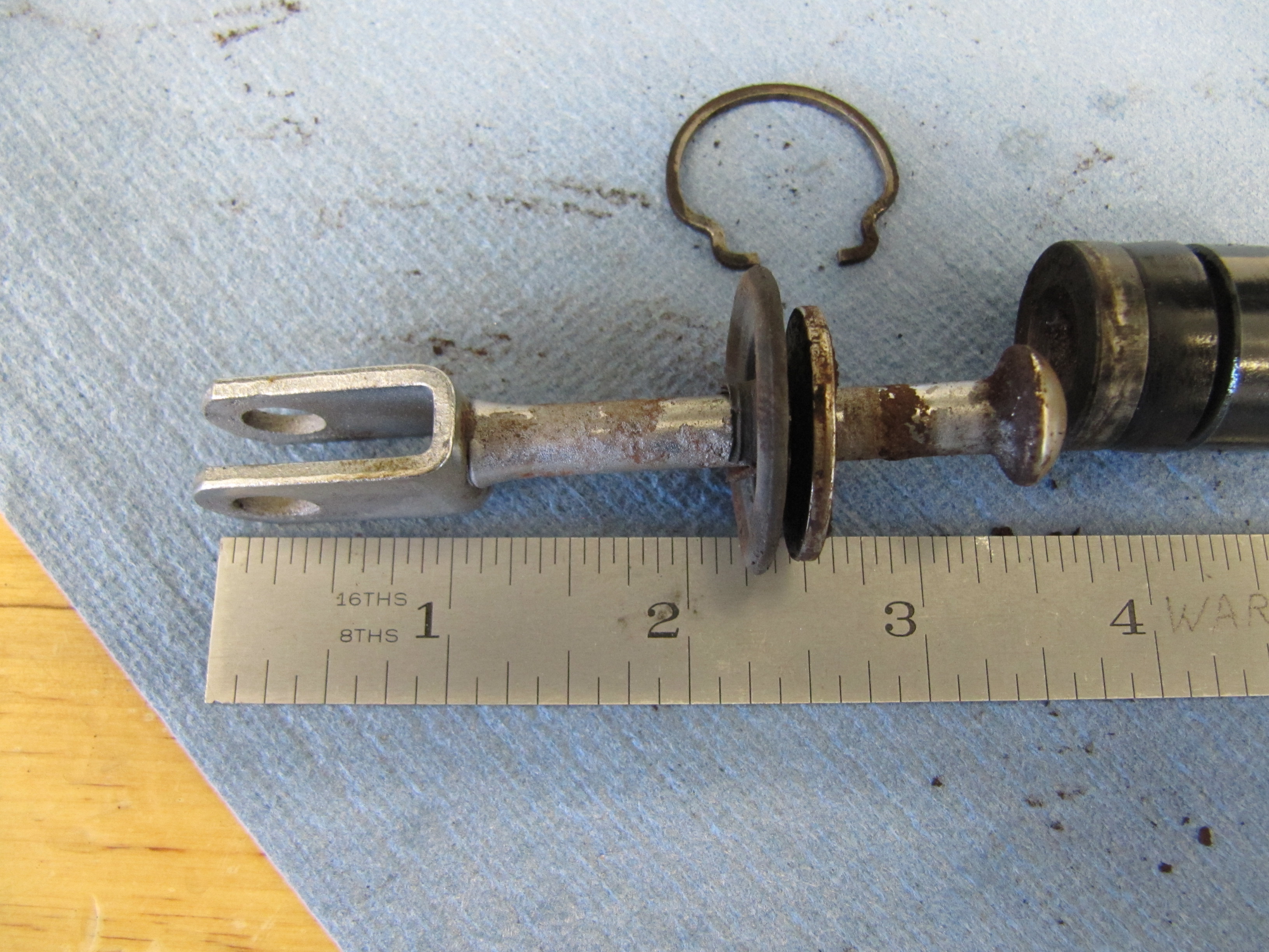
Push Rod Length
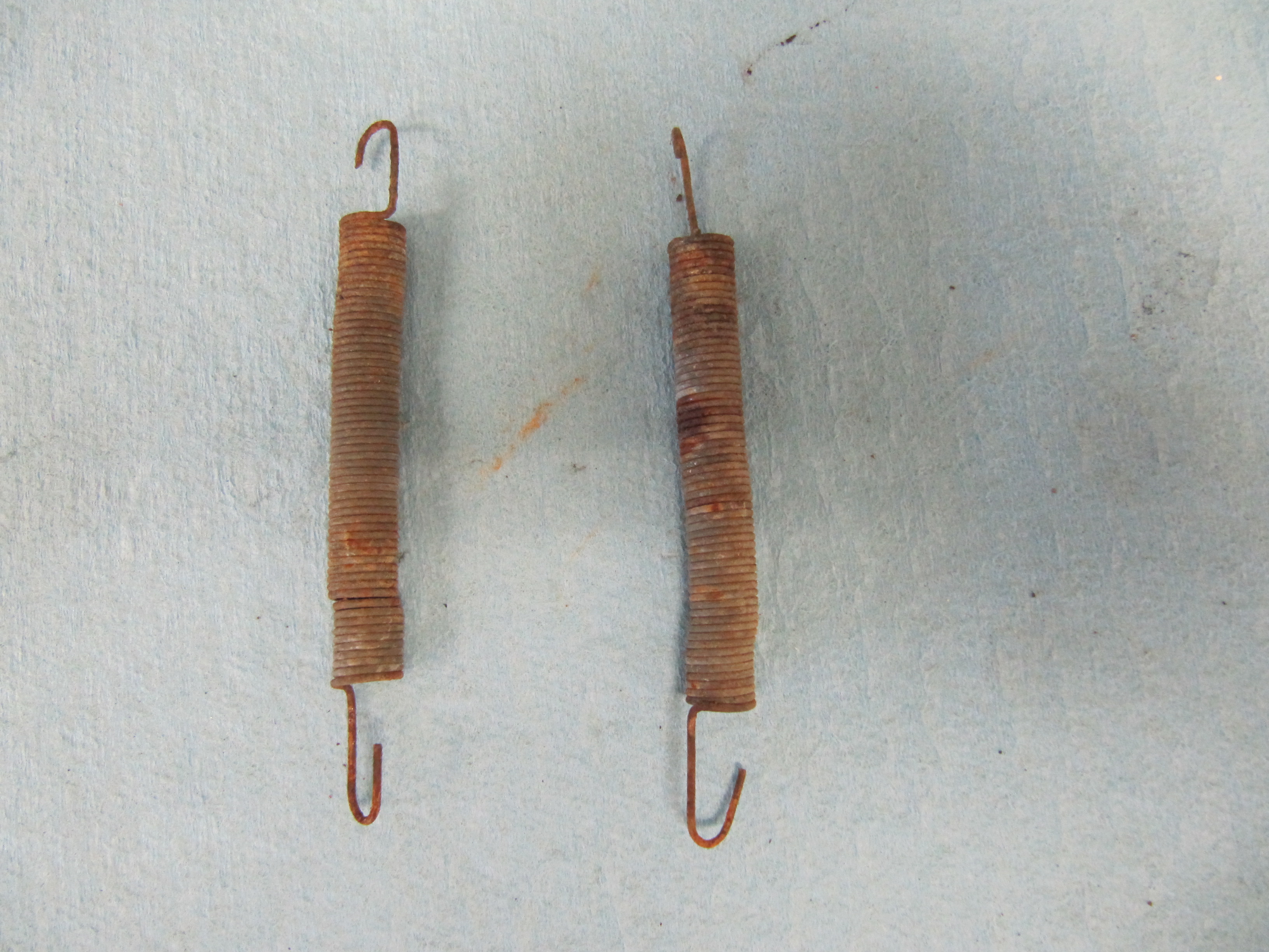
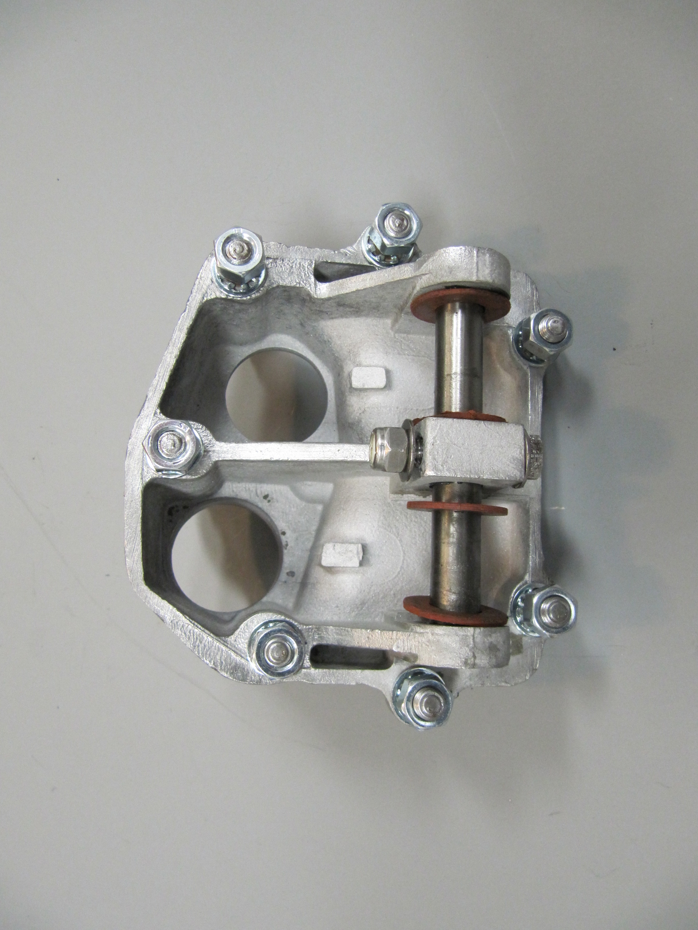
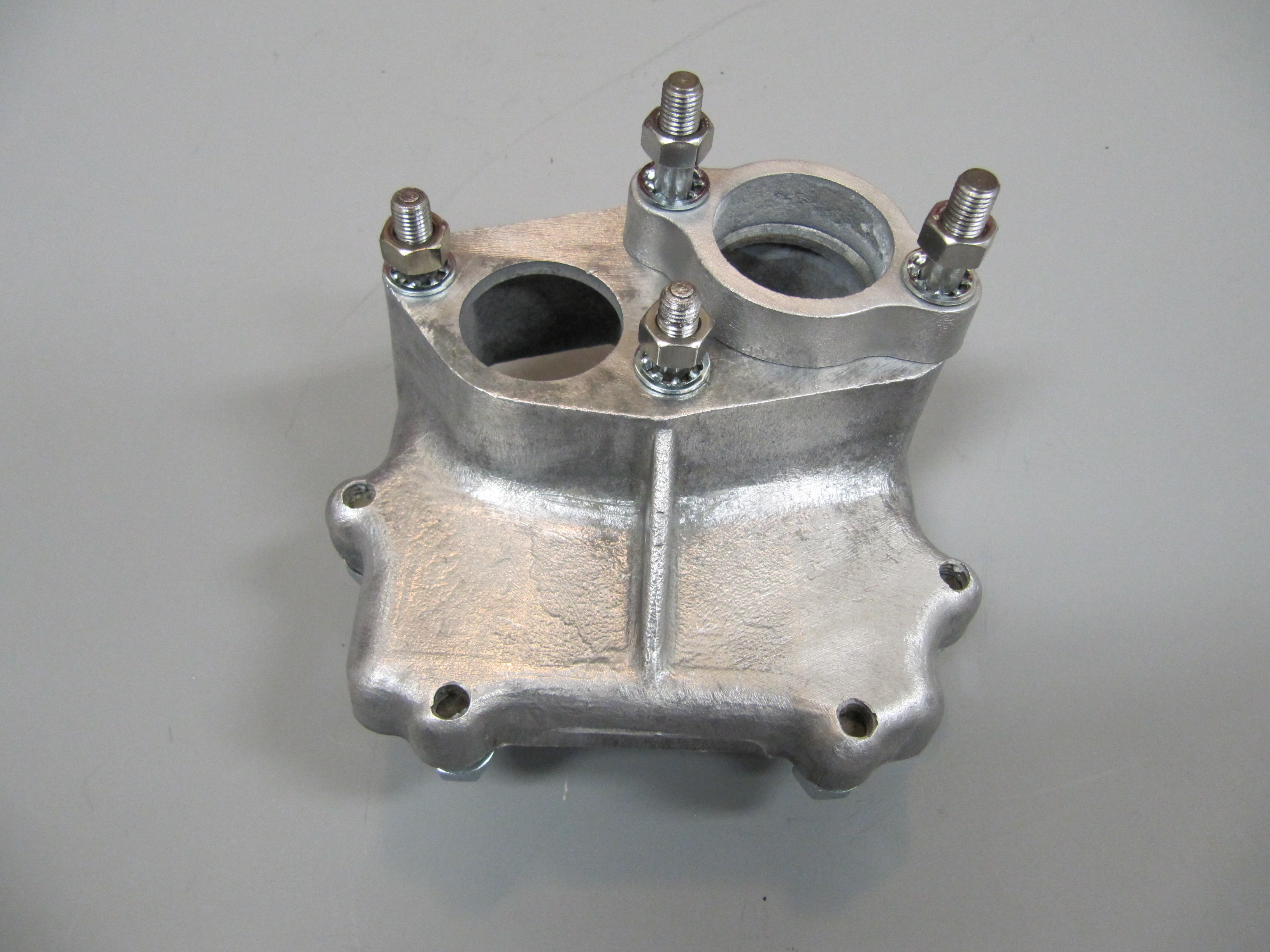
These images show the aluminum brake and clutch housing with the pedals, return springs and fibre washers.
Pedal Housing
Pedals in Housing
Return Springs
The clutch master cylinder and reservoir removal is described under the “Gearbox and Clutch” post found at this link: https://valvechatter.com/?cat=639.
After the clevis pins are removed, the 1/4″ – 28 x 1 1/2″ hex bolt and nylock nut can be removed from the central pedestal. This bolt holds the pedal shaft in place. The shaft was then knocked out with a punch and hammer. Each pedal could then be removed along with the return springs and two fiber washers for each pedal. All parts were cleaned and the housing was then reassembled.
Brake & Clutch Master Cylinder Housing and Pedals
Brake & Clutch Master Cylinder Housing and Pedals
Seven 5/16″ – 24 studs are located in the housing to secure the assembly to the car’s body structure with hex nuts and a double paper gasket (two gaskets).
I had some difficulty ordering new pedal return springs for the clutch and brake pedals, but after several weeks I finally received the proper parts. I first placed the twin paper gaskets that go between the master cylinder housing and the body on the housing (you cannot get it on after the pedals are on the shaft). I then installed the freshly painted pedal arms and pedals along with new rubber pedal pads. The clevis pins were in good shape so I simply cleaned them up, greased them and reinstalled with new split pins. I then placed the new clutch master cylinder/reservoir on the studs on the housing and tightened the two nuts and shake proof washers.

Master Cylinder Housing
Pedals mounted to Housing
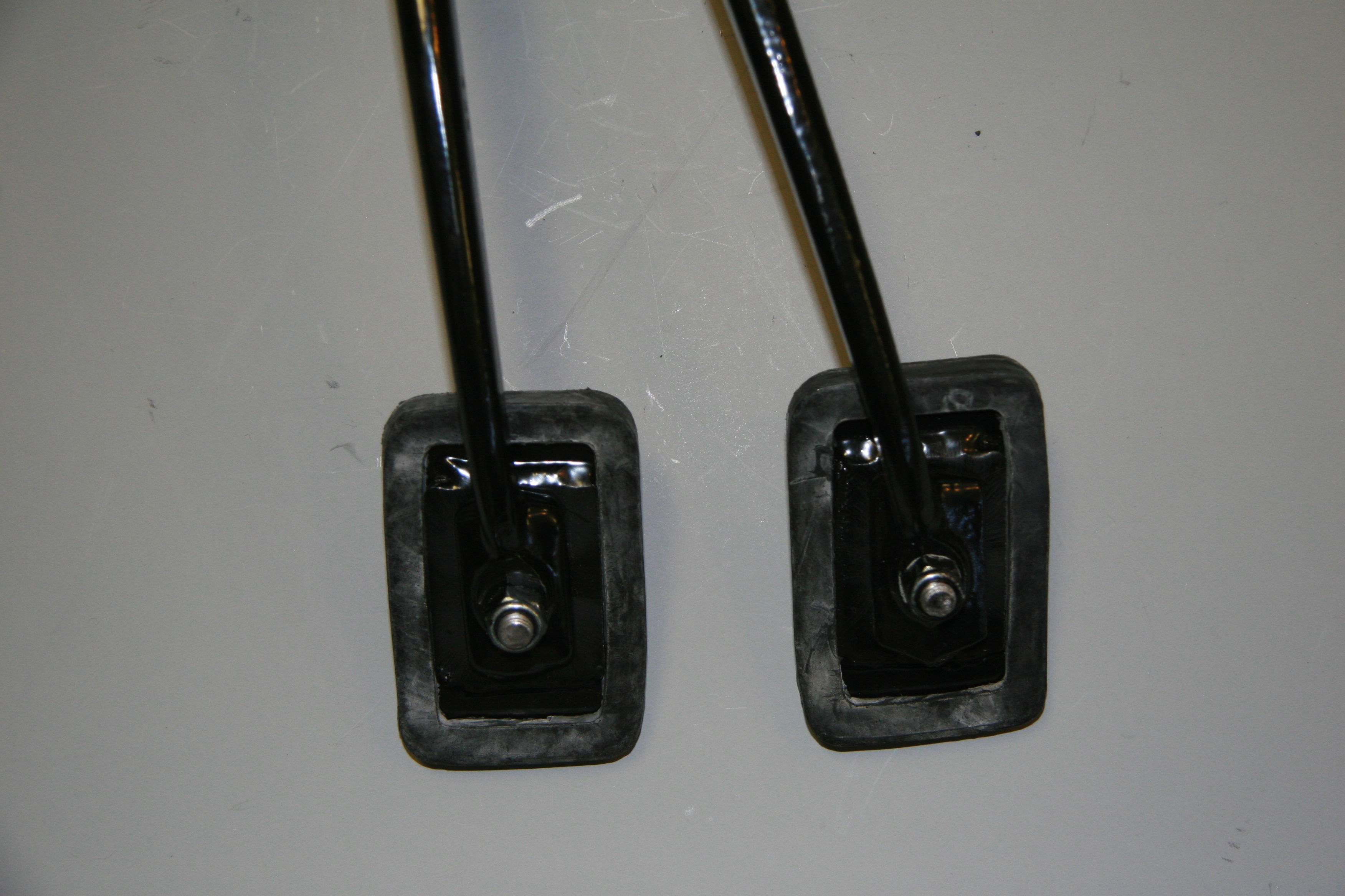
New Pedal Rubbers

Clutch Master Cylinder, Reservoir Mounted to Housing with new Pedal Rubber
The pedal assembly was installed in the car. A double gasket was mounted between the aluminum base and the car body. The assembly can be inserted through the hole in the body if the pedal pads are removed. After installation the brake master was fitted and the clevis and split pin were inserted to connect the pedal to the master cylinder push rod.
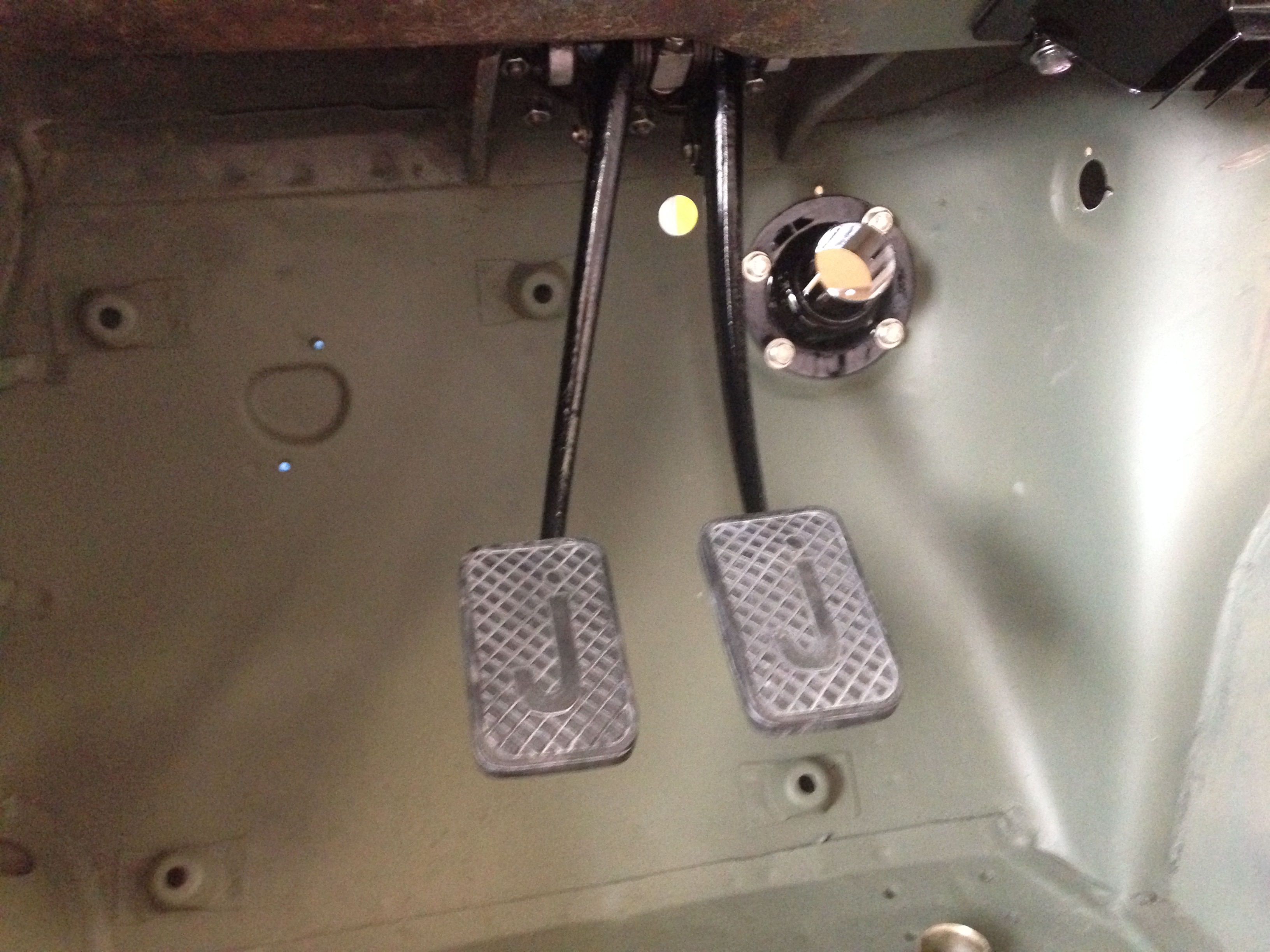
Pedal Assembly Installed
Bleeding the Hydraulic System
After checking all of my connection points one more time to make sure everything was tight, I put a couple of inches of DOT 4 brake fluid into the fluid reservoir and let that drain for a few minutes to see if I had any leaks close to the reservoir. It turned out that I did, but I was able to take care of that in fairly short order. I then filled the reservoir and let gravity work its magic for about thirty minutes.
I like to use a syringe to pull fluid through the pipes to the bleeder valves. I use one like this with a clear hose about 10″ long to connect the syringe to a bleeder valve.
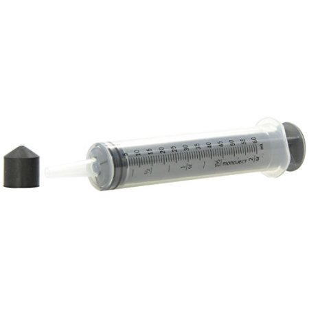
Brake Fluid Syringe
I find that using the syringe speeds up the bleeding process. Everyone has their preferred ways of bleeding. I put some grease around the bleeder screws to help prevent any air from entering the system through the bleeder threads and then I attach the syringe hose to the bleeder, crack open the valve and slowly pull the syringe extracting air and ultimately fluid from the line.
I start with the LH rear bleeder, move to the RH rear bleeder, then the LH front bleeder and finally the RH front bleeder. In this fashion I move from the bleeder farthest away from the four-way hydraulic junction mounted on the RH engine bay valance to the closest.
Since my system was completely dry, I had to suck air out of the LH rear bleeder valve five or six times before I began to draw fluid with the air bubbles. I would open the bleeder, draw the syringe, close the bleeder, and release the syringe tube from the bleeder to push the syringe piston fully downward in the cylinder and expel the air. I would then reconnect to the bleeder and repeat the process. The LH rear bleeder valve always takes the longest. Each successive bleeder takes fewer and fewer applications of the syringe.
After completing the process, I still ask for the assistance of my wife to push the brake pedal for me as I continue to monitor each of the brake bleeders in the same sequence. I open a bleeder valve, she pushed the pedal down and leaves it down. I then close the valve and tell her to release the pedal upward. I then open the valve again and she pushes to the floor once more and that process continues until all air is expelled.
For the “pedal pushing process” I use a small container with fluid in the bottom and a short clear hose to collect the fluid that is expelled from each bleeder. Because the syringe process gets the vast majority of air out of the system, the “pedal pushing” takes very little time. I find that my spouse prefers this two step method of the syringe followed by pedal pushing because it keeps her in the garage for much less time than when one relies on “pedal pushing” alone!
Fortunately, we encountered no additional leaks and the process produced a nice firm pedal.
I then basically replicated the process for the clutch. The slave cylinder can at times be a challenge and I find drawing the fluid through the slave with the syringe is particularly helpful. Once I got a good flow of fluid through the slave cylinder, my able assistant used the “pedal pushing process” to finish the job once more. Again, with positive results.