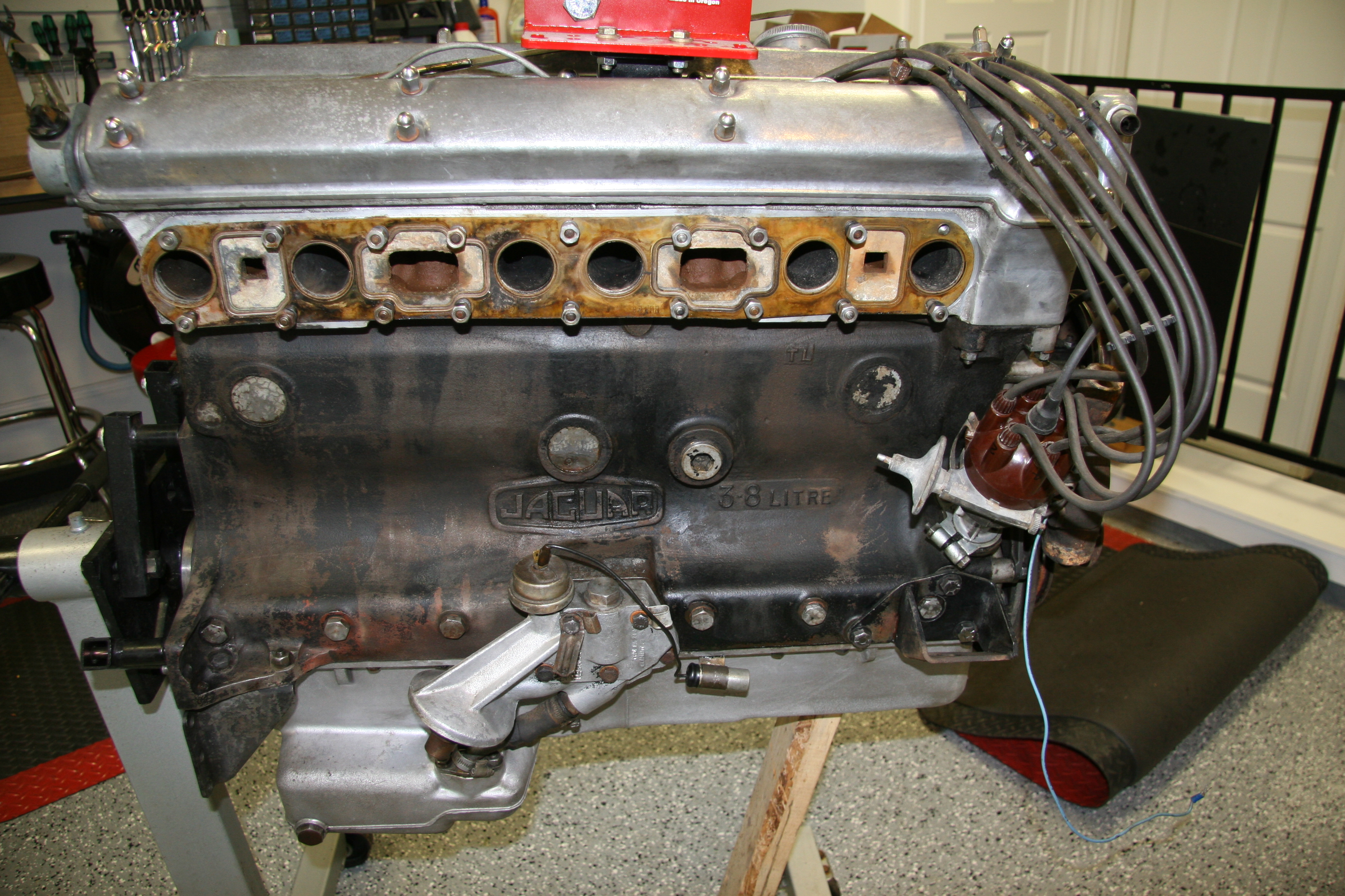
Engine Mounting
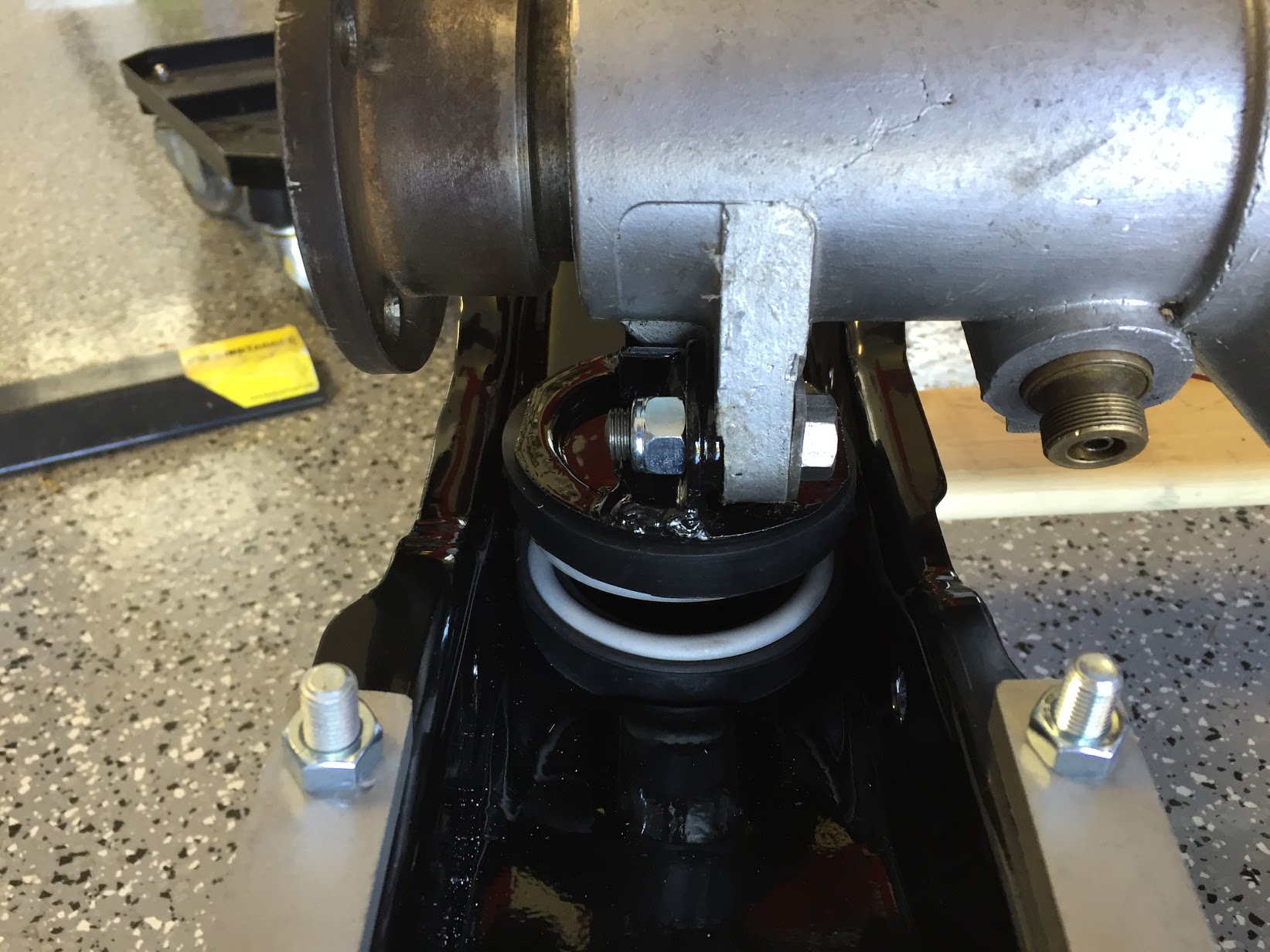
Rear Engine Stabiliser
The rear of the engine is attached to the firewall (dash) of the car via a stabilising link with a rubber bushing and a rear mount on the firewall with a rubber bushing. I cleaned both components and installed new bushings.
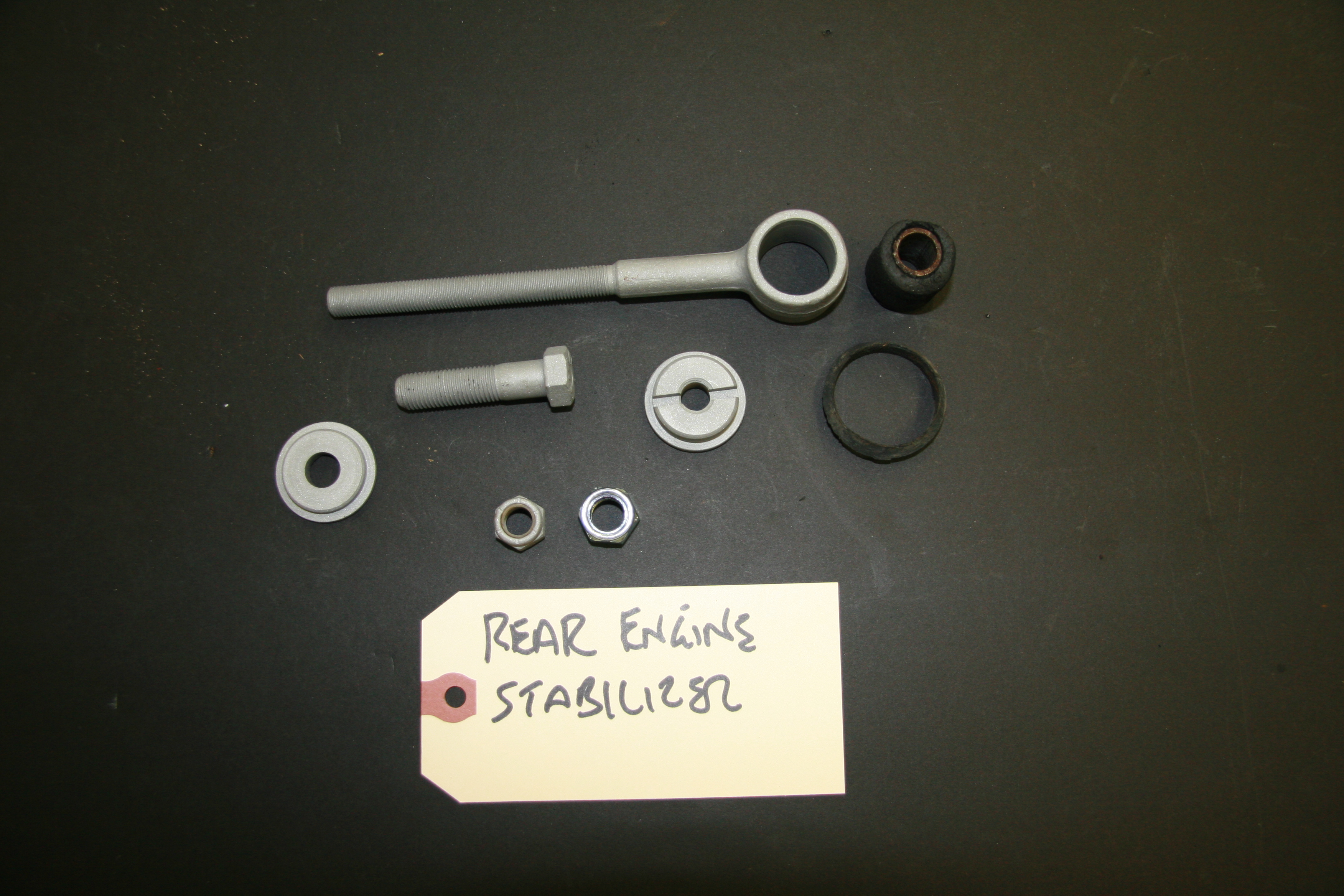
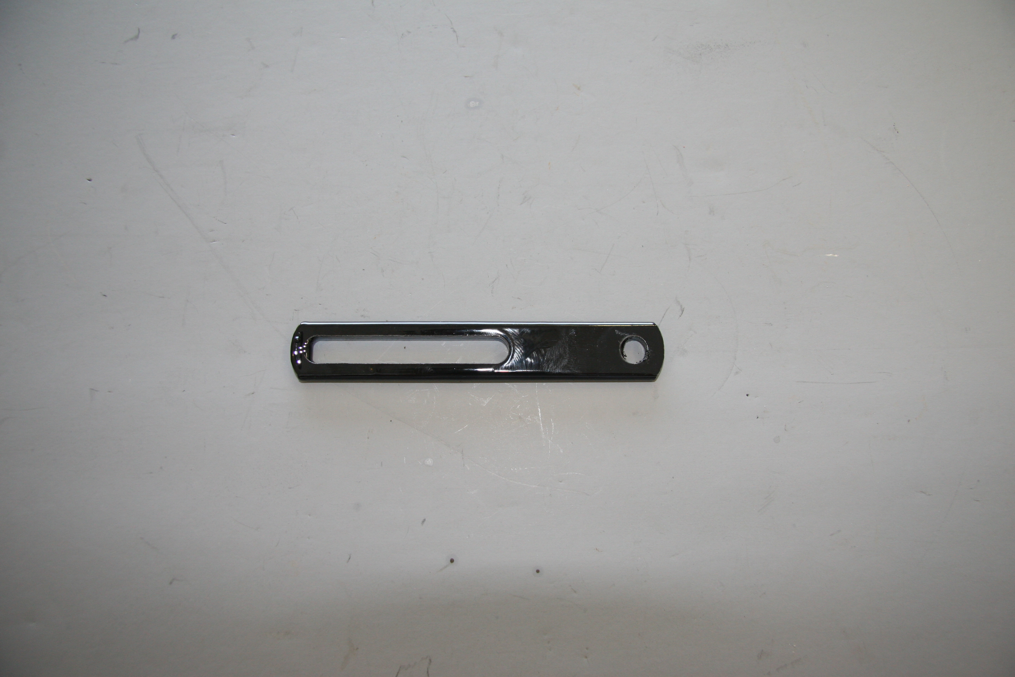
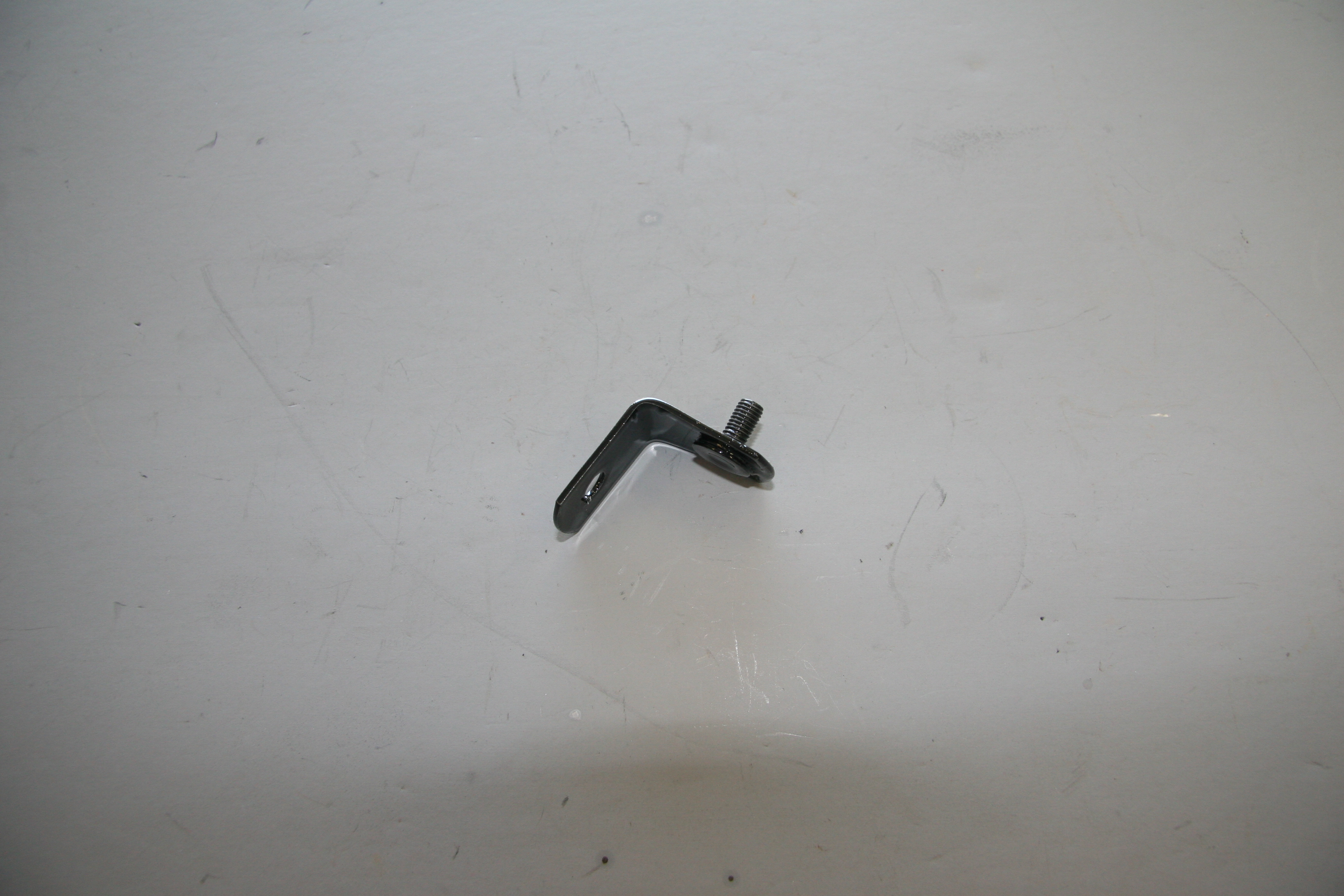
Stabilising Link at Rear of Cylinder Block, Bush, Stepped Washer, Stepped Bush, Nut
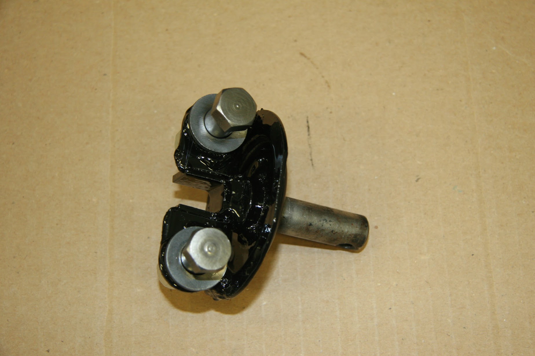
The rubber mounting for the stabiliser link needed to be replaced. I purchased a new one and had the link zink plated. This image shows the mounting and the link as an assembly.
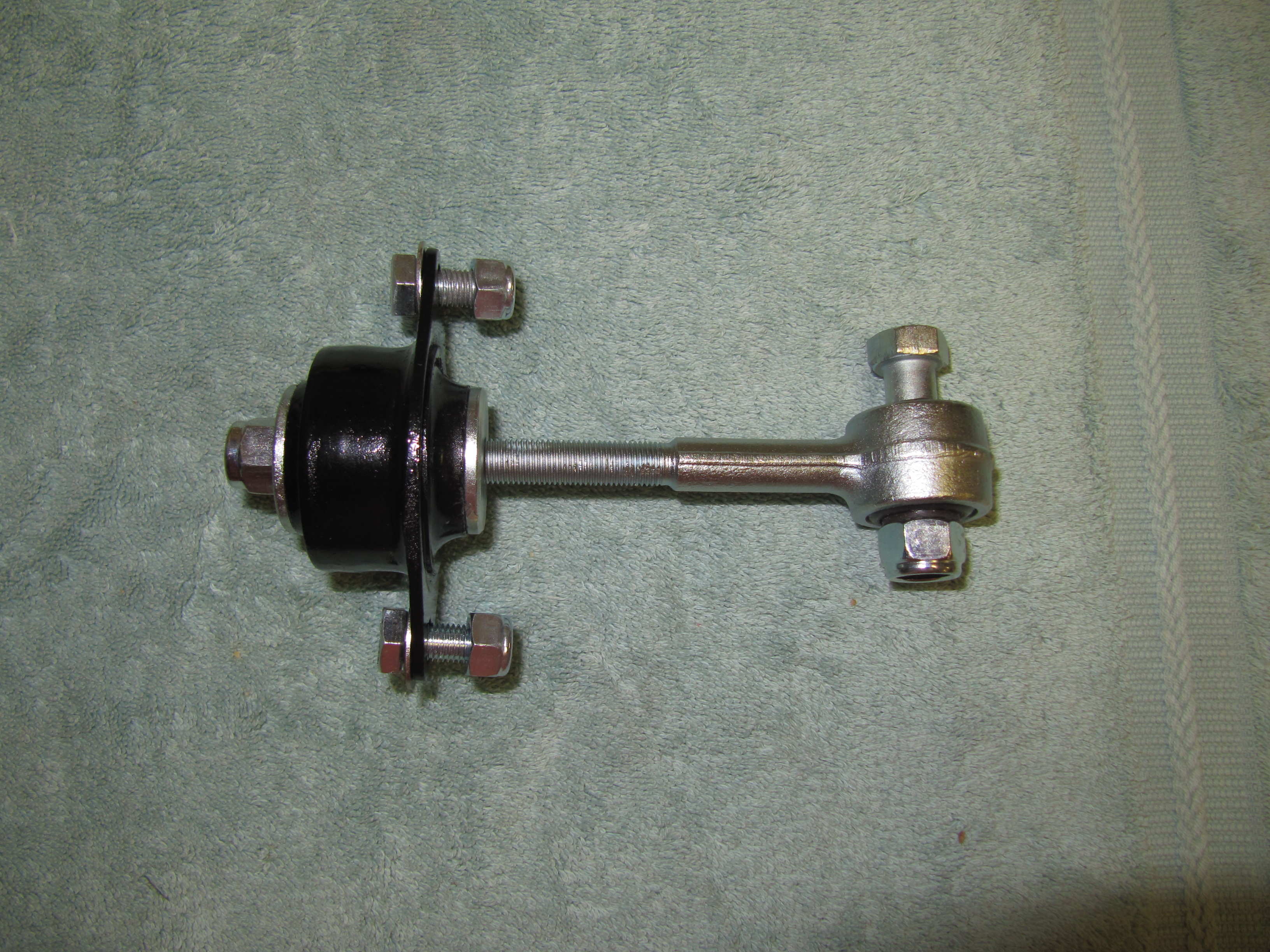
Rear Engine Stabiliser Assembly
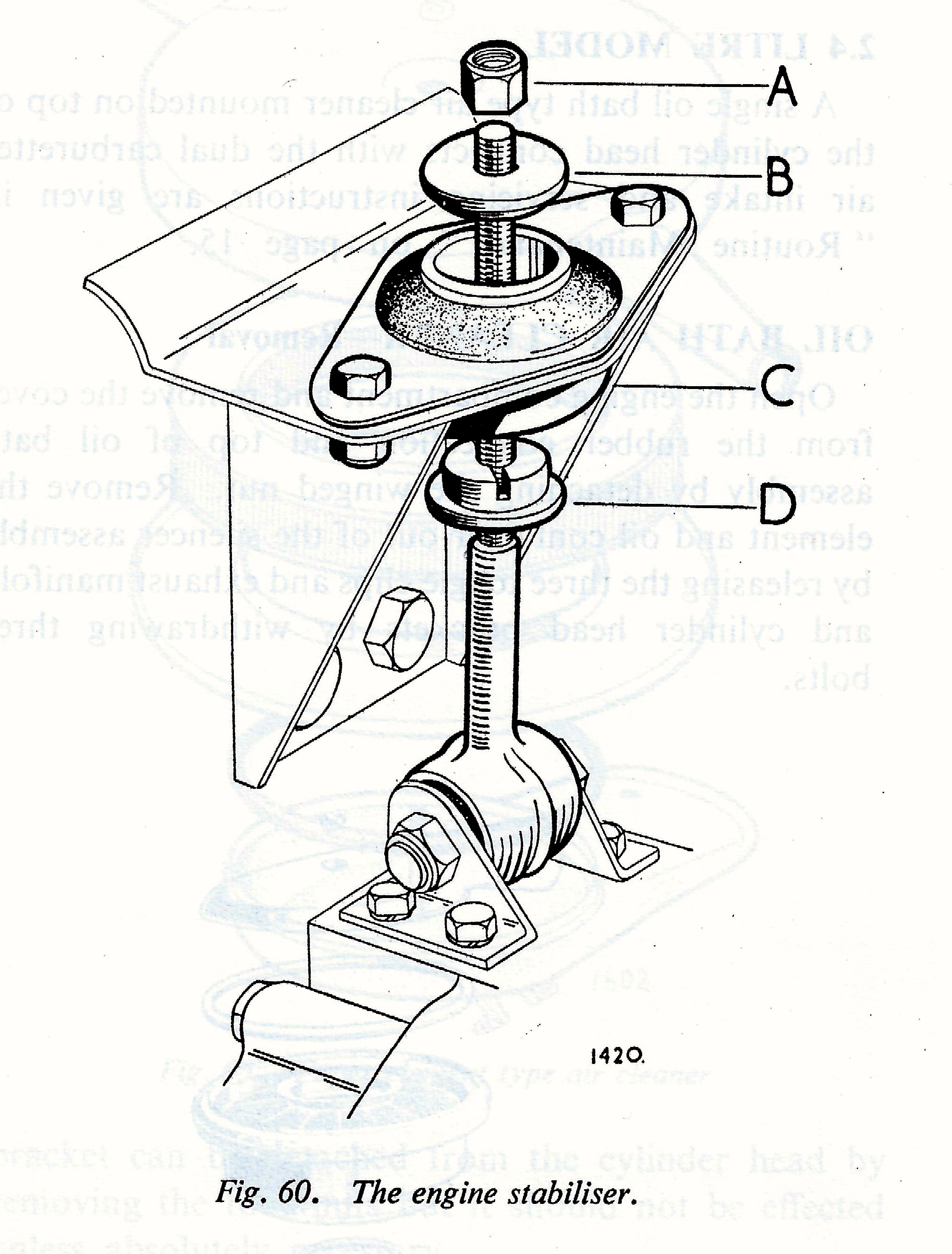
Engine Stabiliser
As can be seen in the illustration above, the stabiliser link is secured to the bell housing via two brackets, the LH and RH bearing brackets, mounting the stabilizing links at the bottom. The brackets are fastened to the bell housing with four 5/16 – 18 x 3/4″ hex bolts with lock washers. The link is fastened to the bracket with a single 7/16″ – 20 x 1-3/4″ hex head bolt with a nylock nut. The link is fastened to the firewall bracket using a stepped bush and stepped washer with a 3/8″ – 24 nylock nut.
Rear Engine Stabiliser Mounted
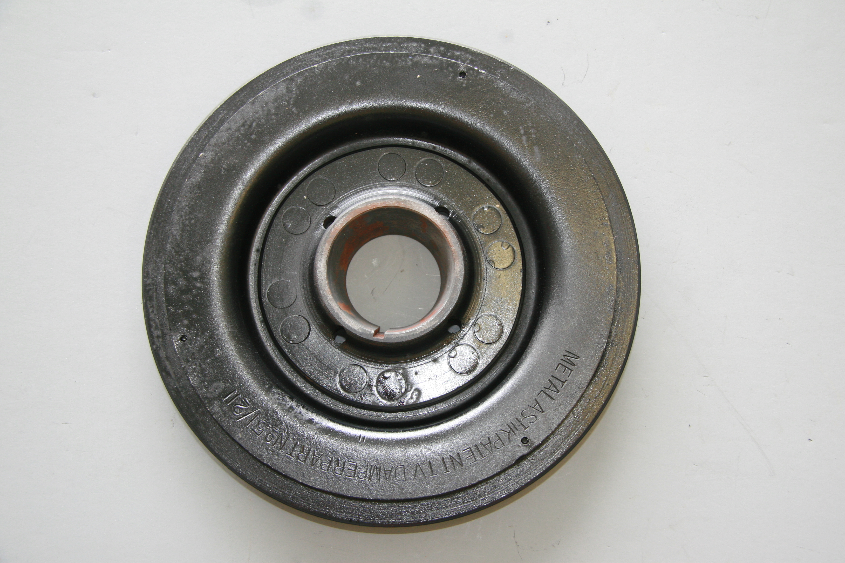
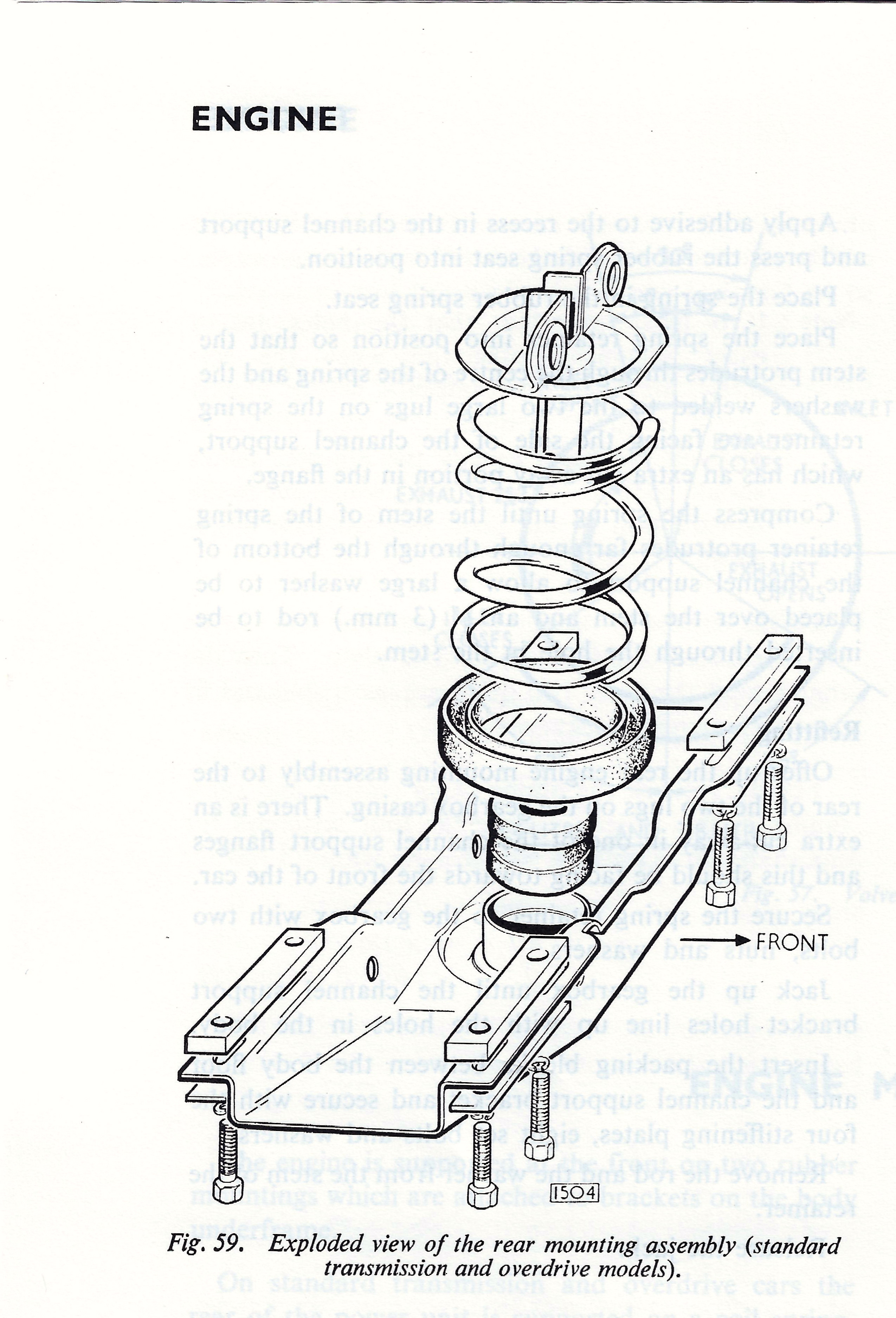
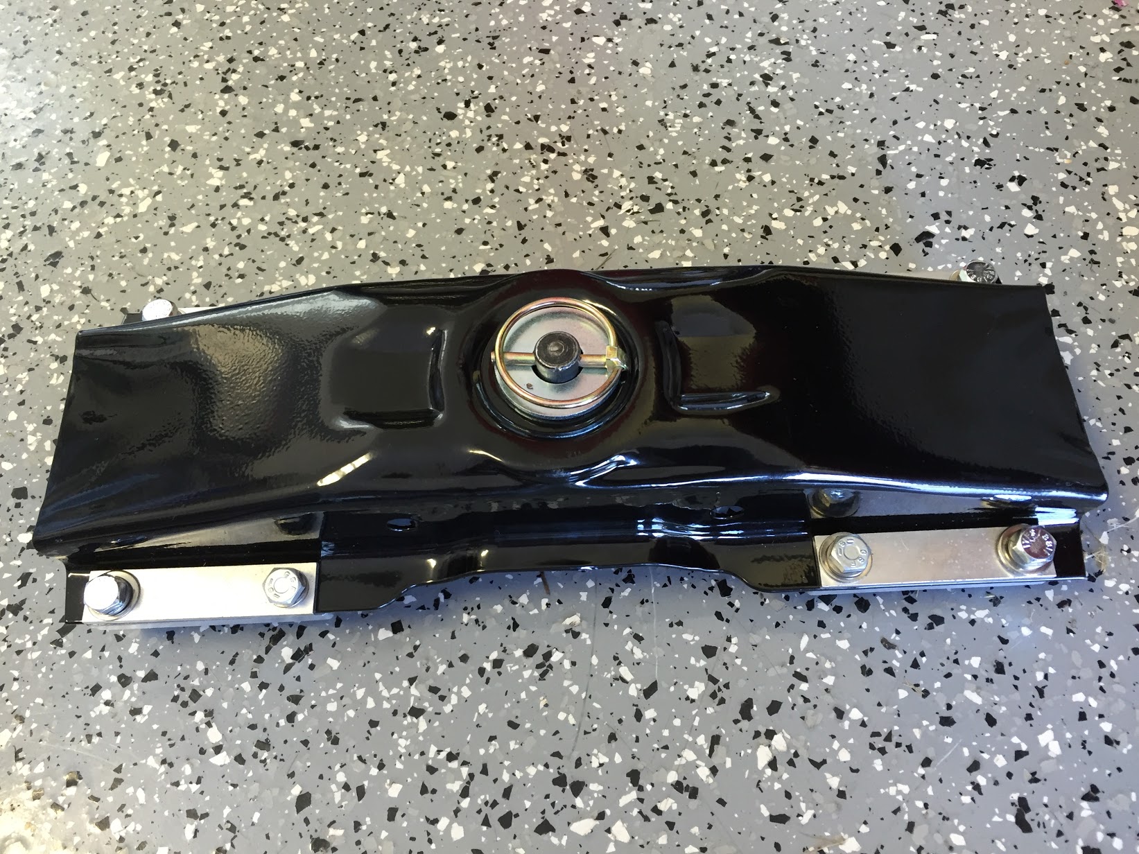
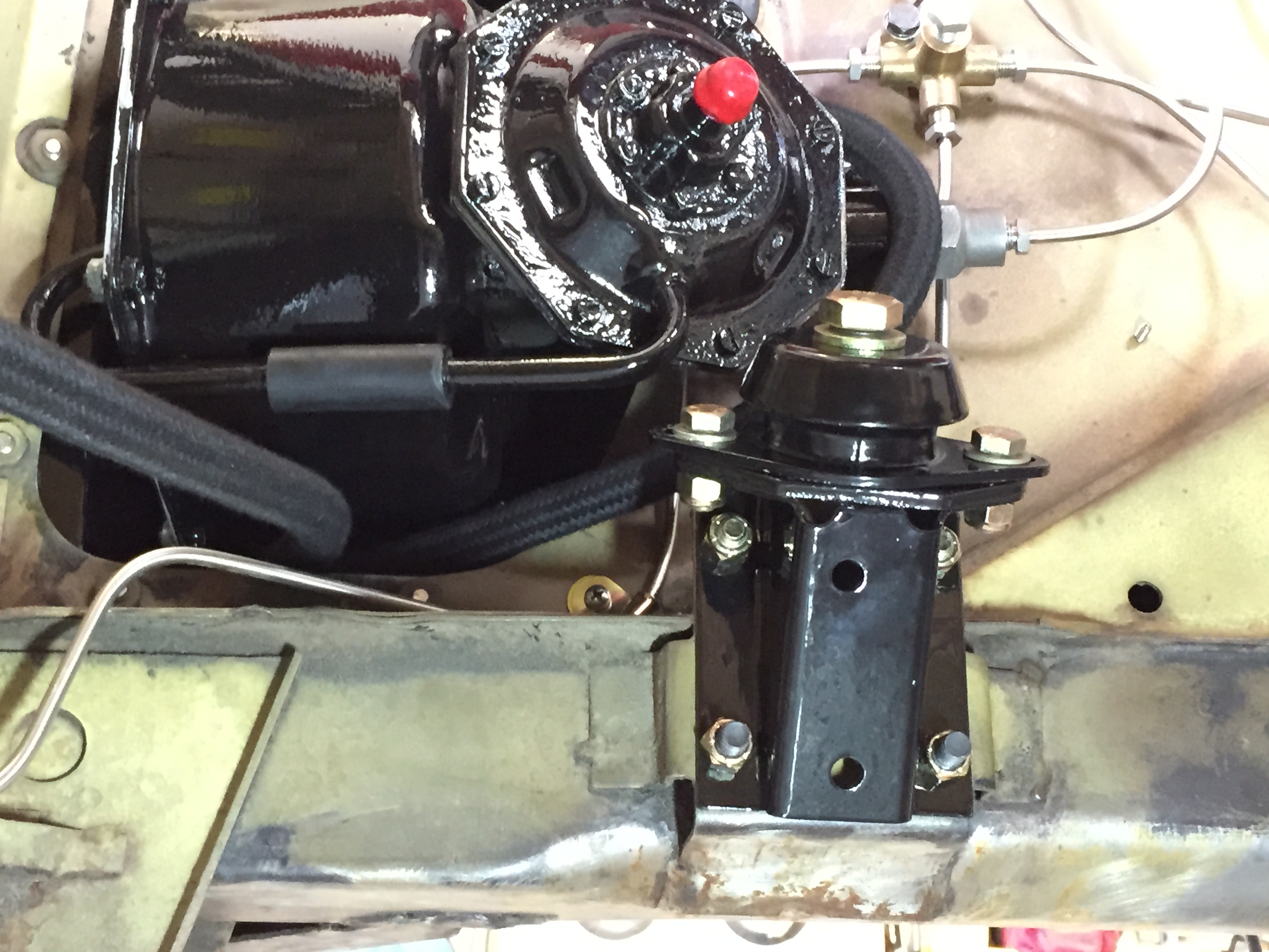
Rear Engine Mount – The Channel Support Assembly
The assembly includes: The channel support, a rubber spring seat, a center rubber busing, the coil spring for rear engine mounting, four aluminum packing blocks between the flange of the channel support and the underside of the floor, eight bolts (5/16″ -24 x 1 3/8″), eight flat washers, eight split locking washers, and four stiffening plates. The Spring Retainer Assembly for Rear Engine Mounting is attached to the gearbox.
Rear Engine Mount
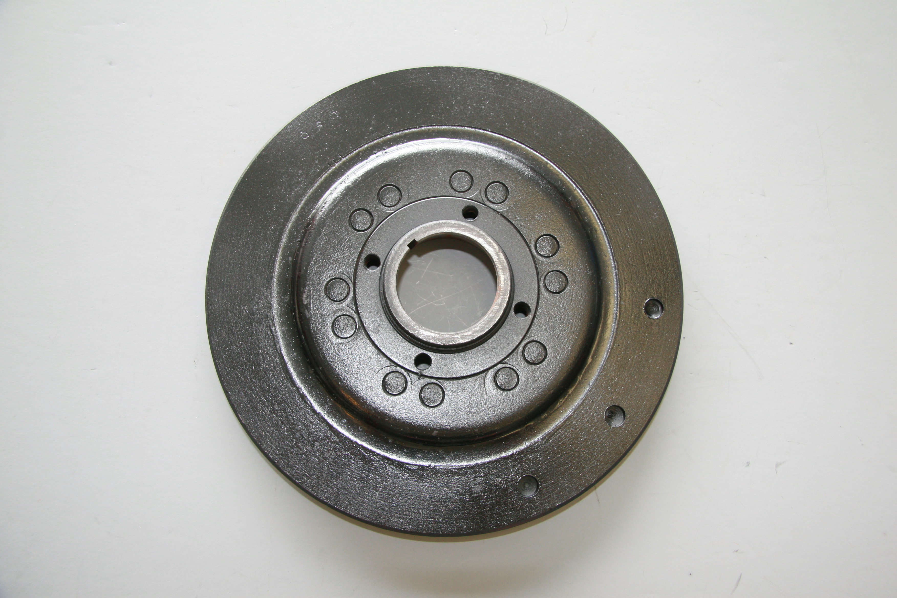
Engine Rear Mounting Assembly
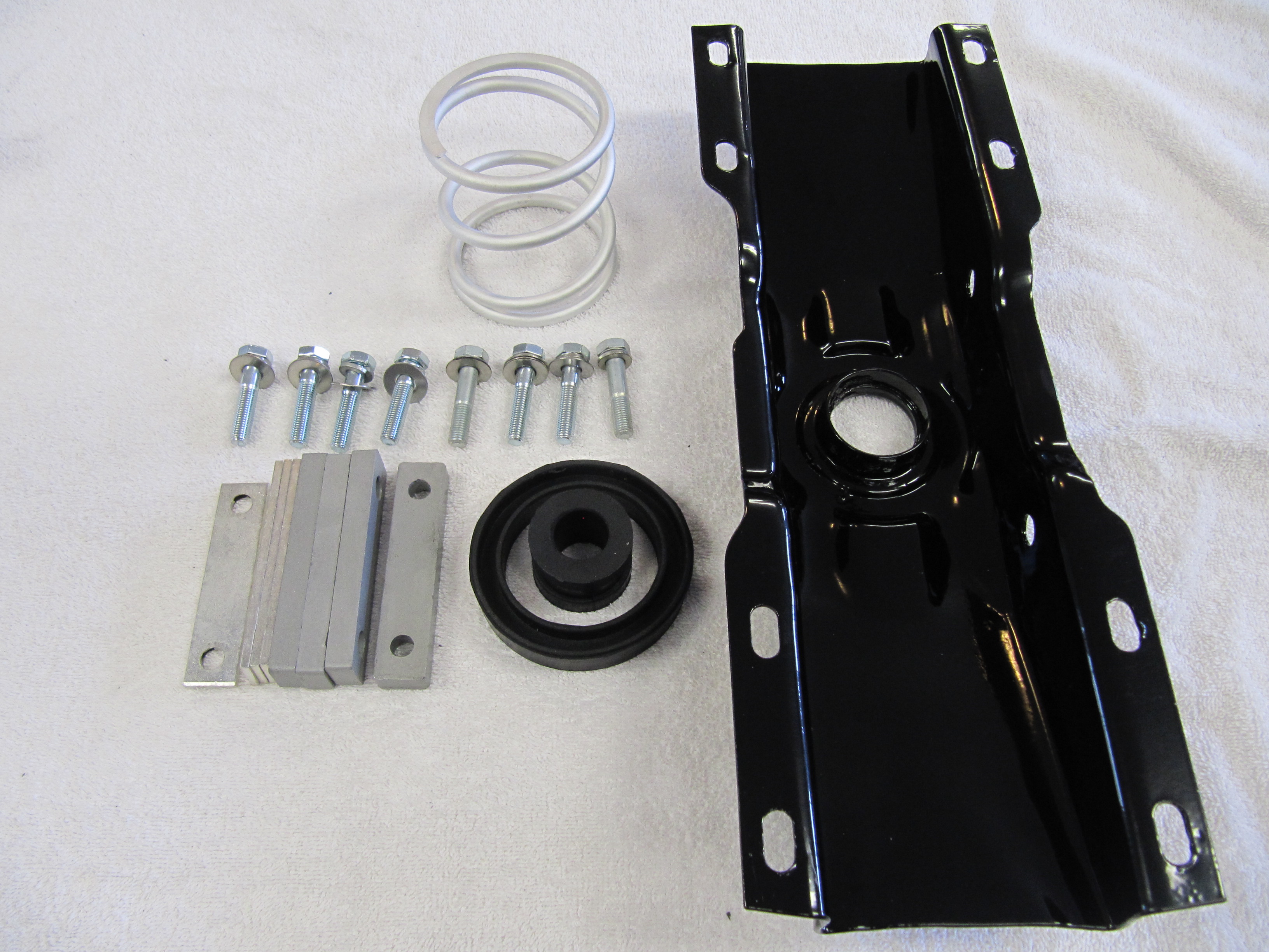
The rear engine mounting plate actually supports the tail of the gearbox and it bolts to the superstructure of the car. I cleaned and media blasted the Channel Support component of the assembly and powder coated it. The Assembly includes the channel support as well as its rubber spring seat, the rubber center bush, the spring retainer, the coil spring, the pin assembly, the bolt securing the rear engine mounting to the gearbox, a self-locking nut, four packing blocks and four stiffening plates. I replaced the rubber spring seat and the rubber center bush and the mounting fasteners with new components. The coil spring and stiffening plates were clear cad plated and the aluminum spacers were cleaned and clear-coated.
Support Assembly
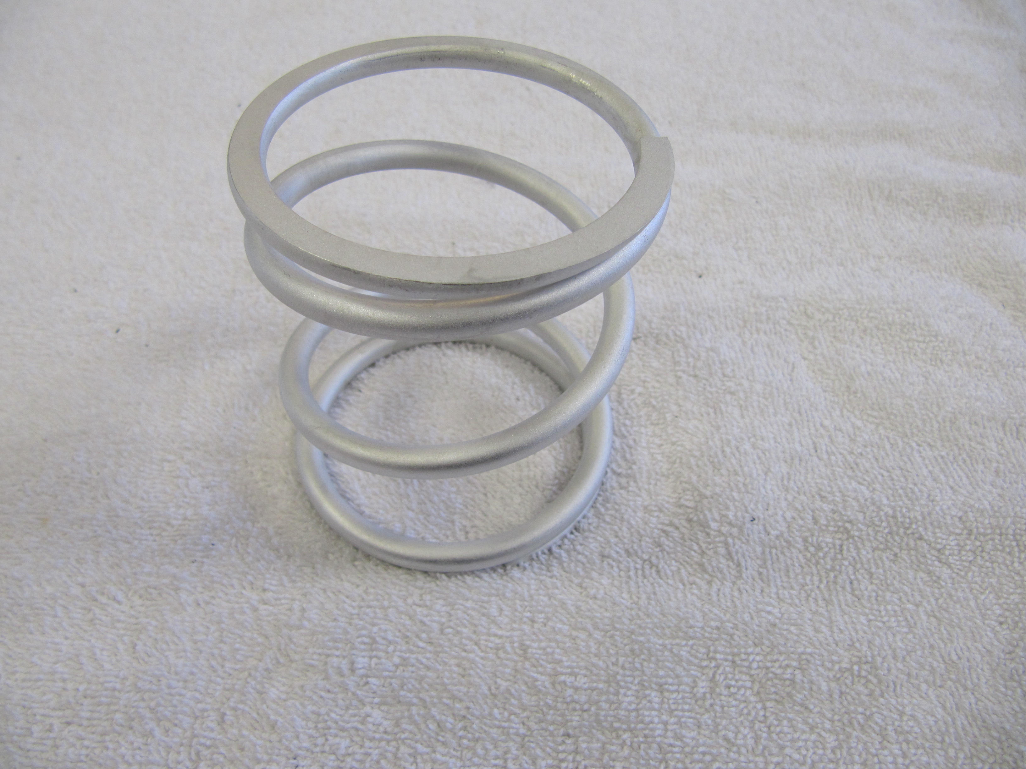
Coil Spring
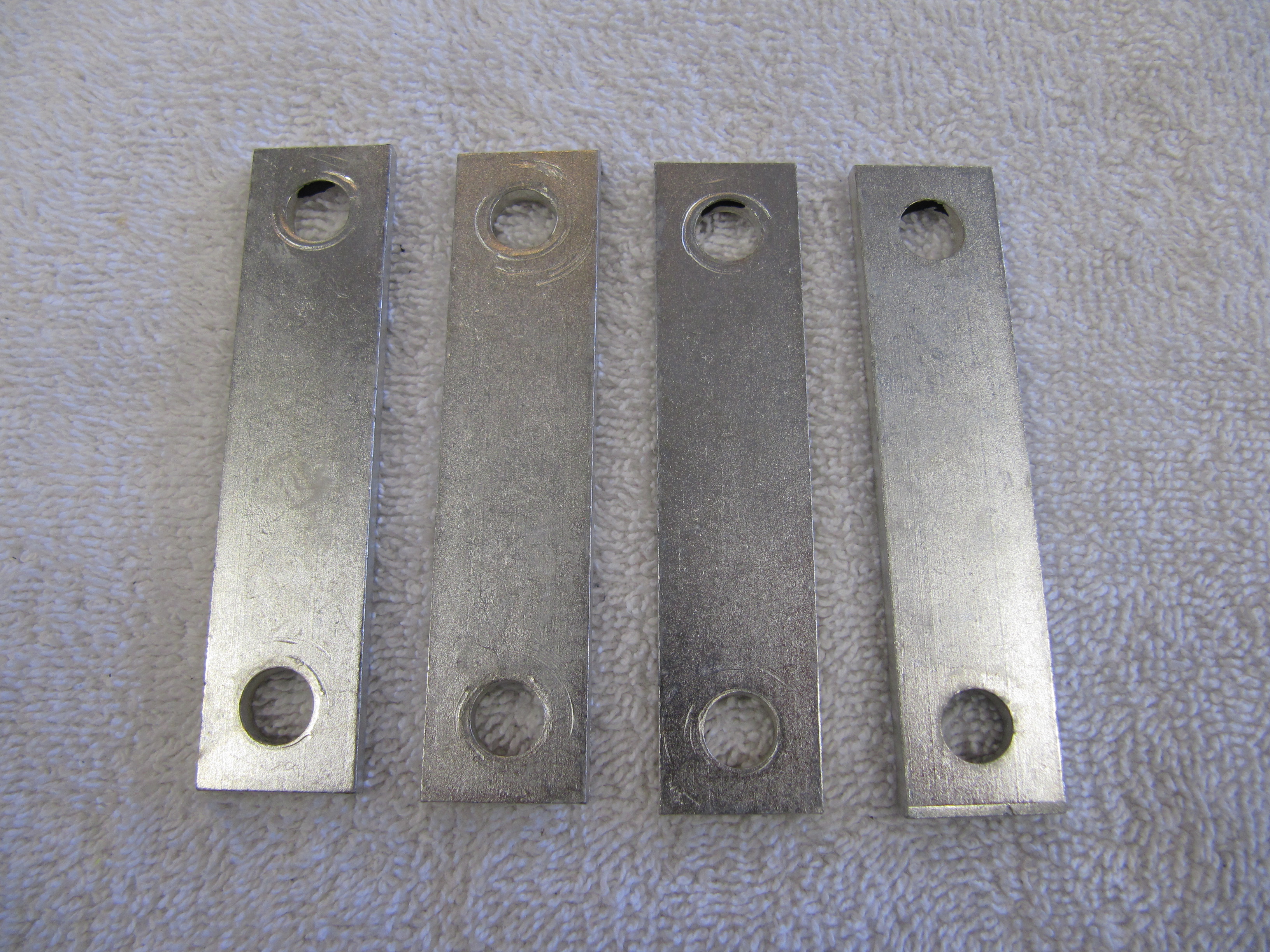
Support Stiffening Plates
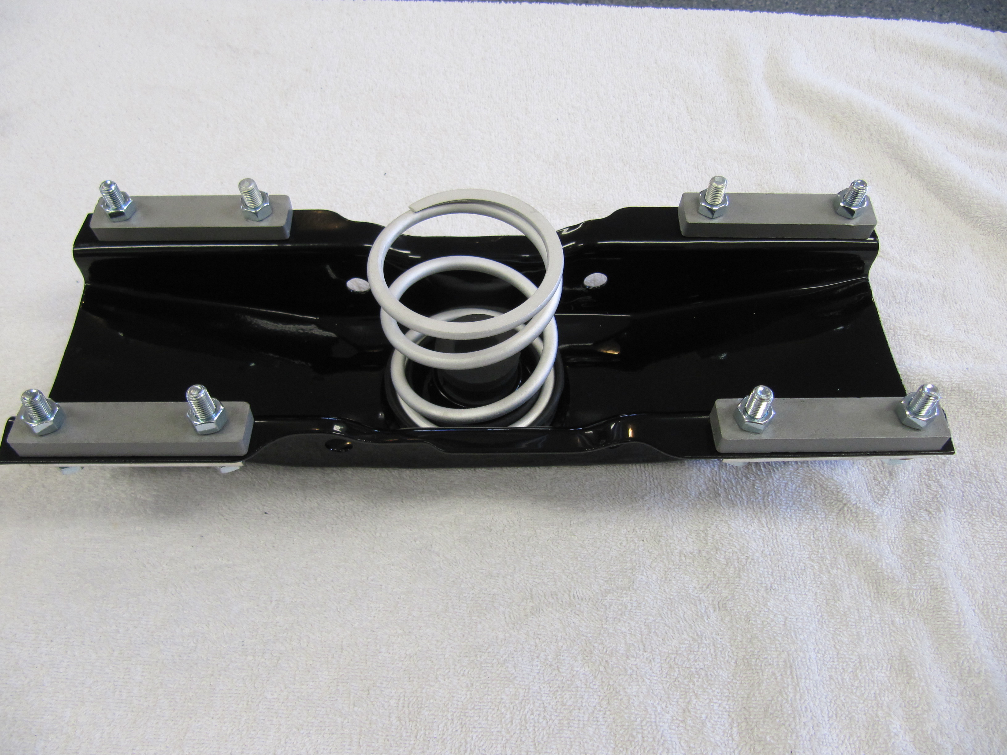
Channel Support Assembly Components for Rear Engine Mounting Assembled
Reassembling and Installing the rear engine mount
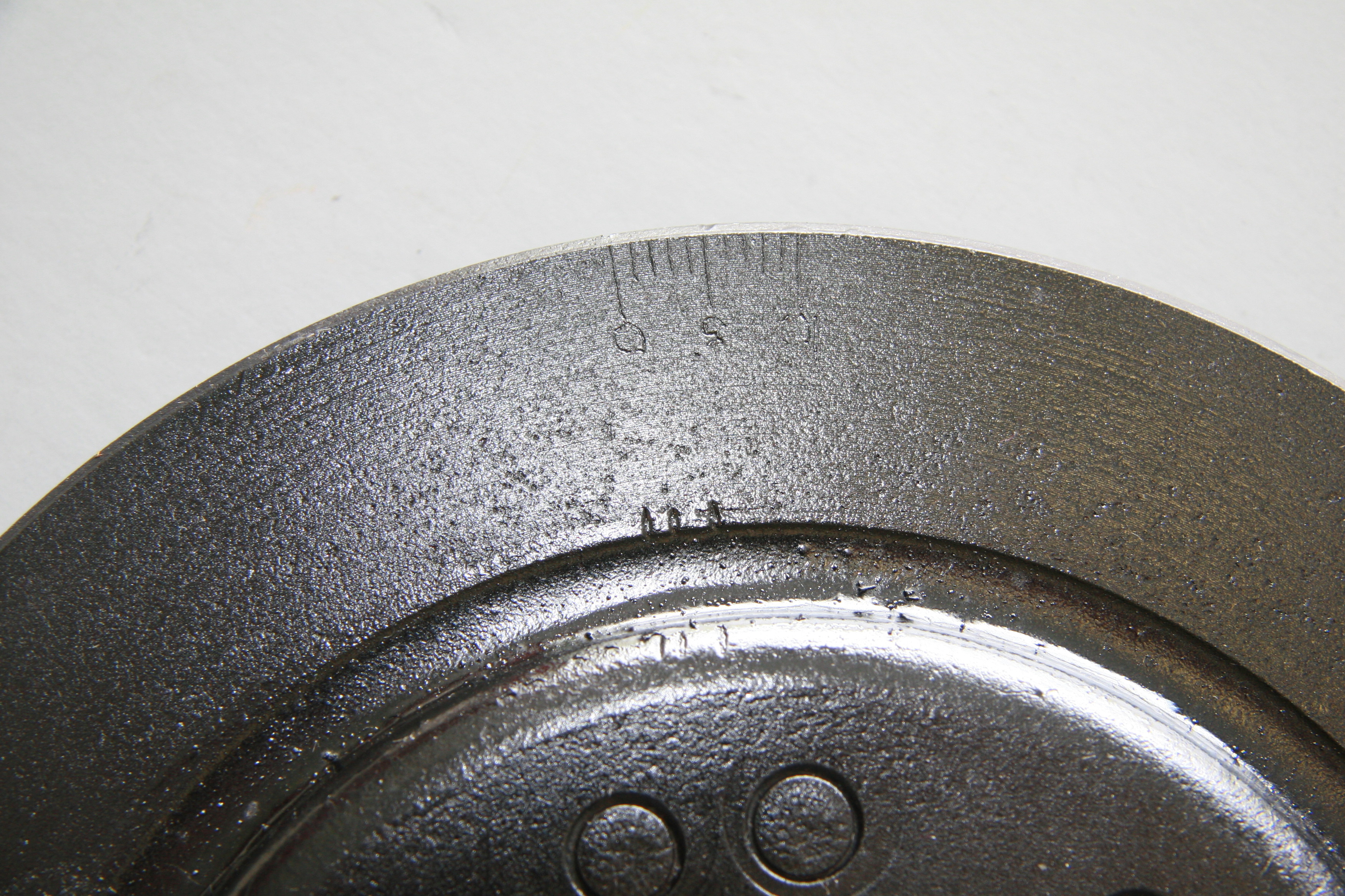
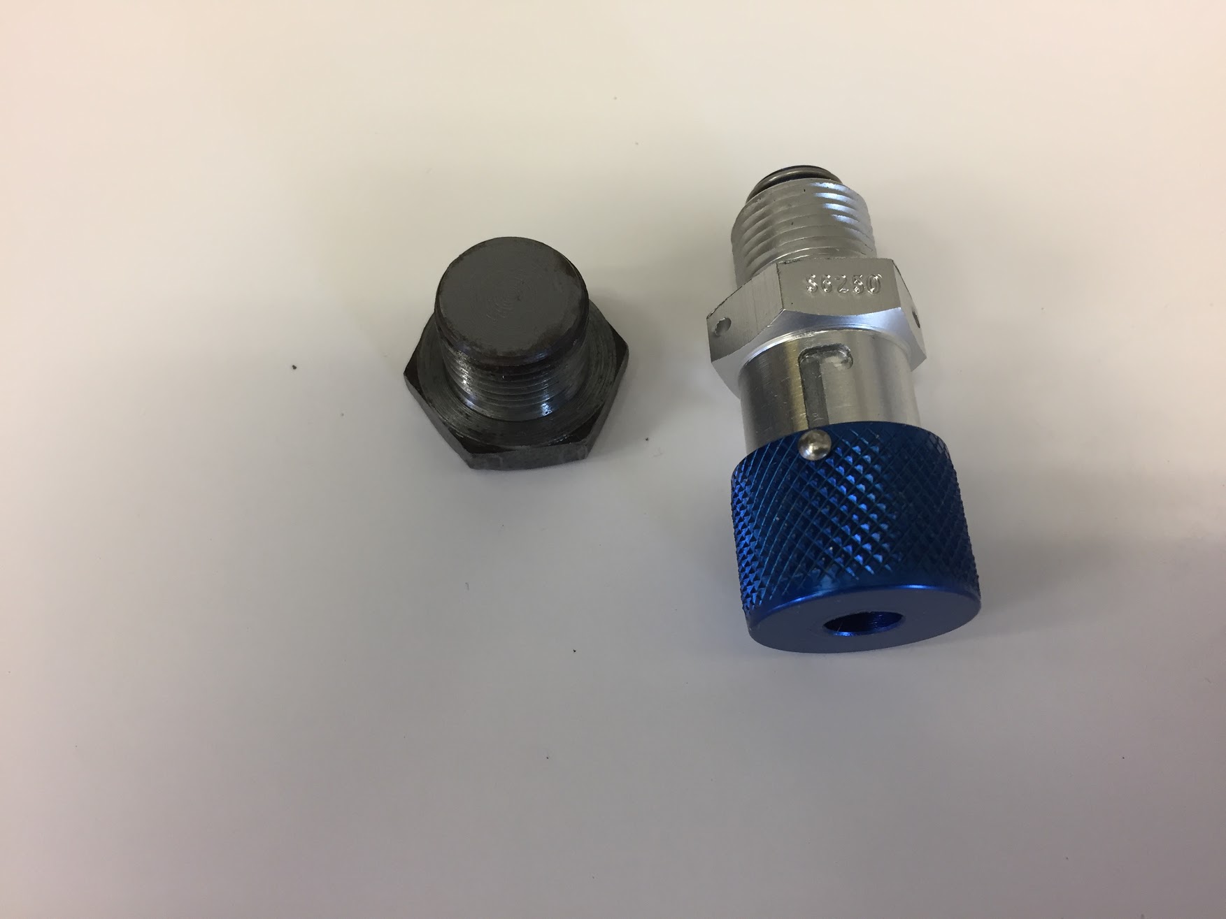
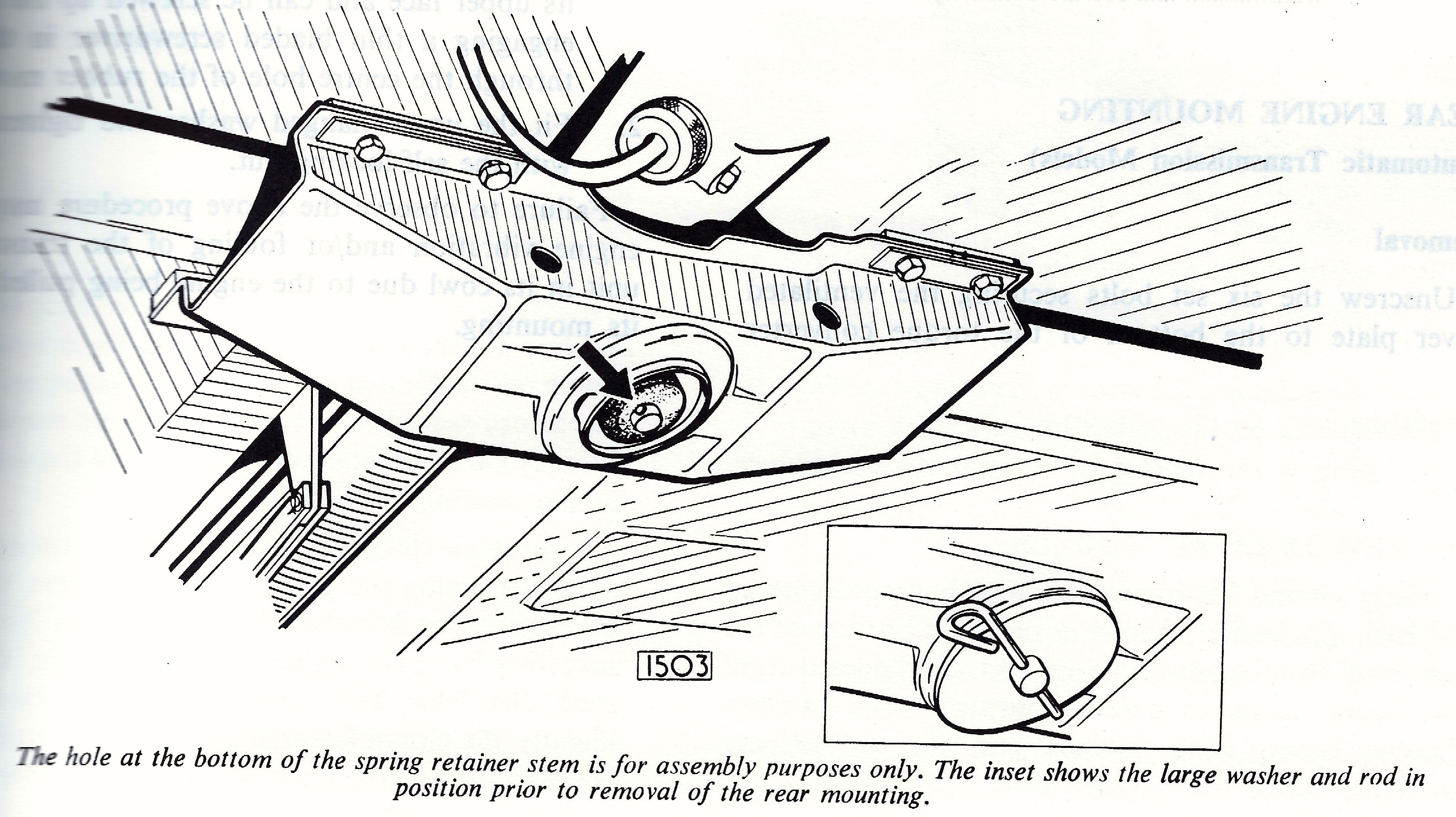
The Jaguar Service Manual provides instruction for installing the rear mount. Place the spring retainer into position so that the stem protrudes through the centre of the spring and the washers welded to the two large lugs on the spring retainer are facing the side of the channel support, which has an extra cut-away portion in the flange. Compress the spring until the stem of the spring retainer protrudes far enough through the bottom of the channel support to allow a large washer to be placed over the stem and an 1/8” (3 mm) rod to be inserted through the hole in the stem.” Of course, nothing is said about HOW to compress the spring. I found that I needed a press to do the job and it makes the task quite easy.
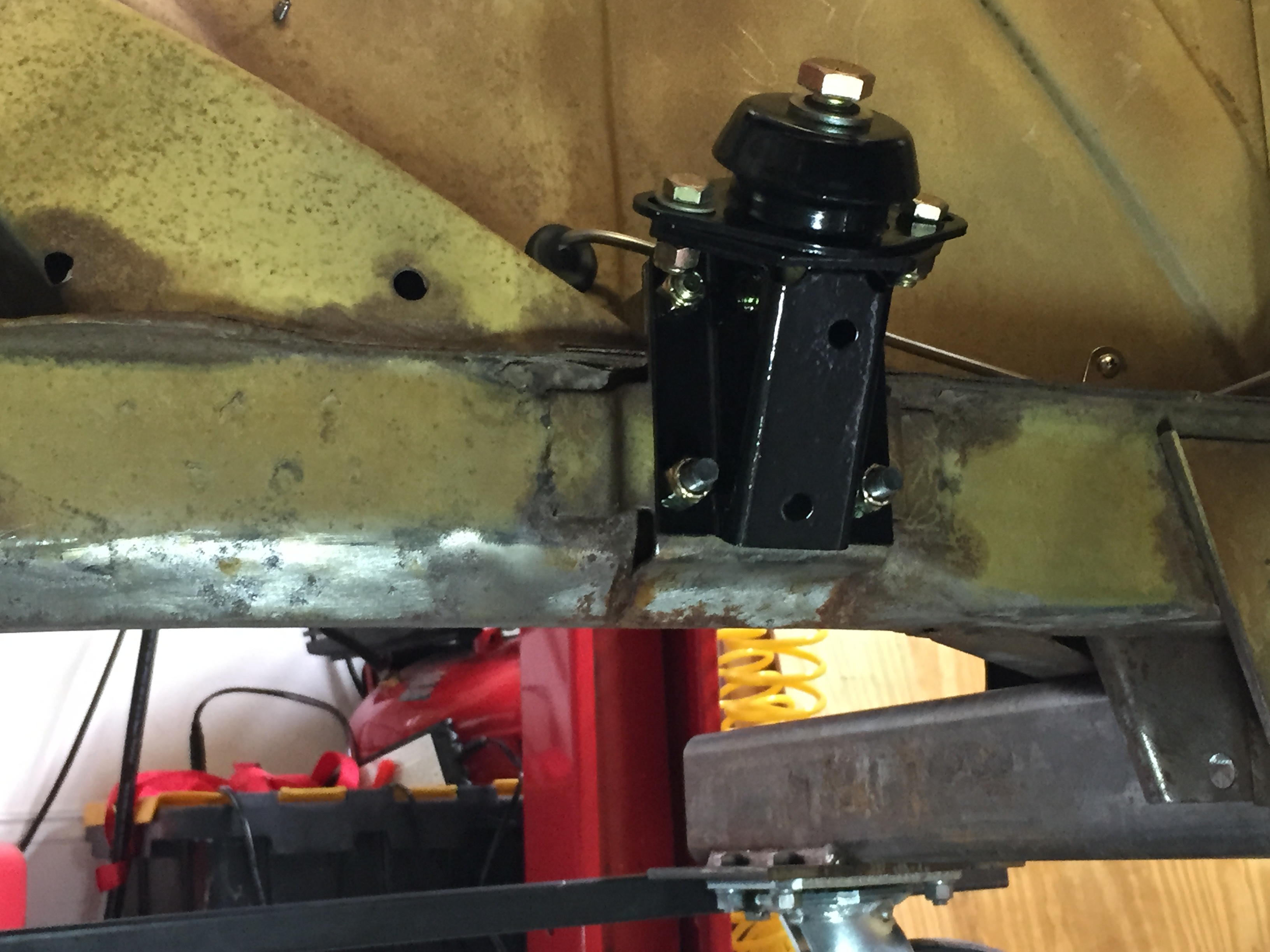
Rear Engine Mount with Pin Installed
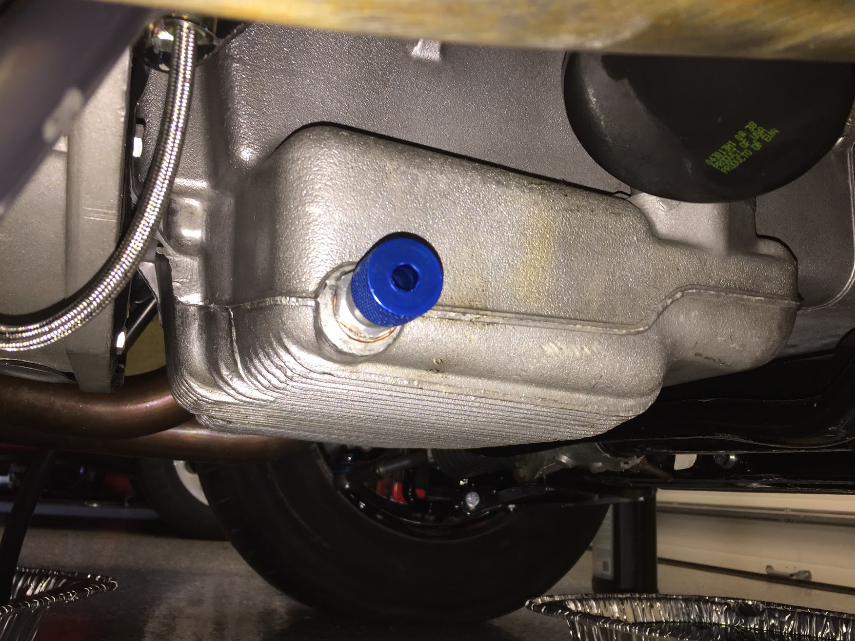
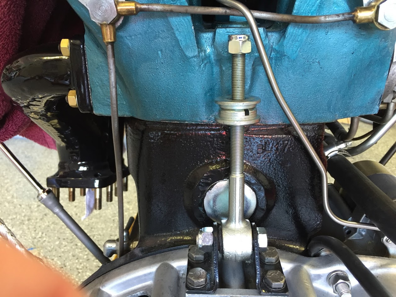
Rear Engine Mount Fixed to Gearbox
Spring Retainer
Two 7/16″-20 x 1-1/2″ hex head bolts with nylock nuts are used to secure the rear channel support (rear engine mount) to the gearbox. Note that the spring retainer needs to face the proper way as seen in the diagram and photos with the bolt heads to the front of the gearbox. The rear engine mount is now ready to old to the chassis with the eight (8) hex head mounting bolts.
Rear Engine Mount Attached to Gearbox
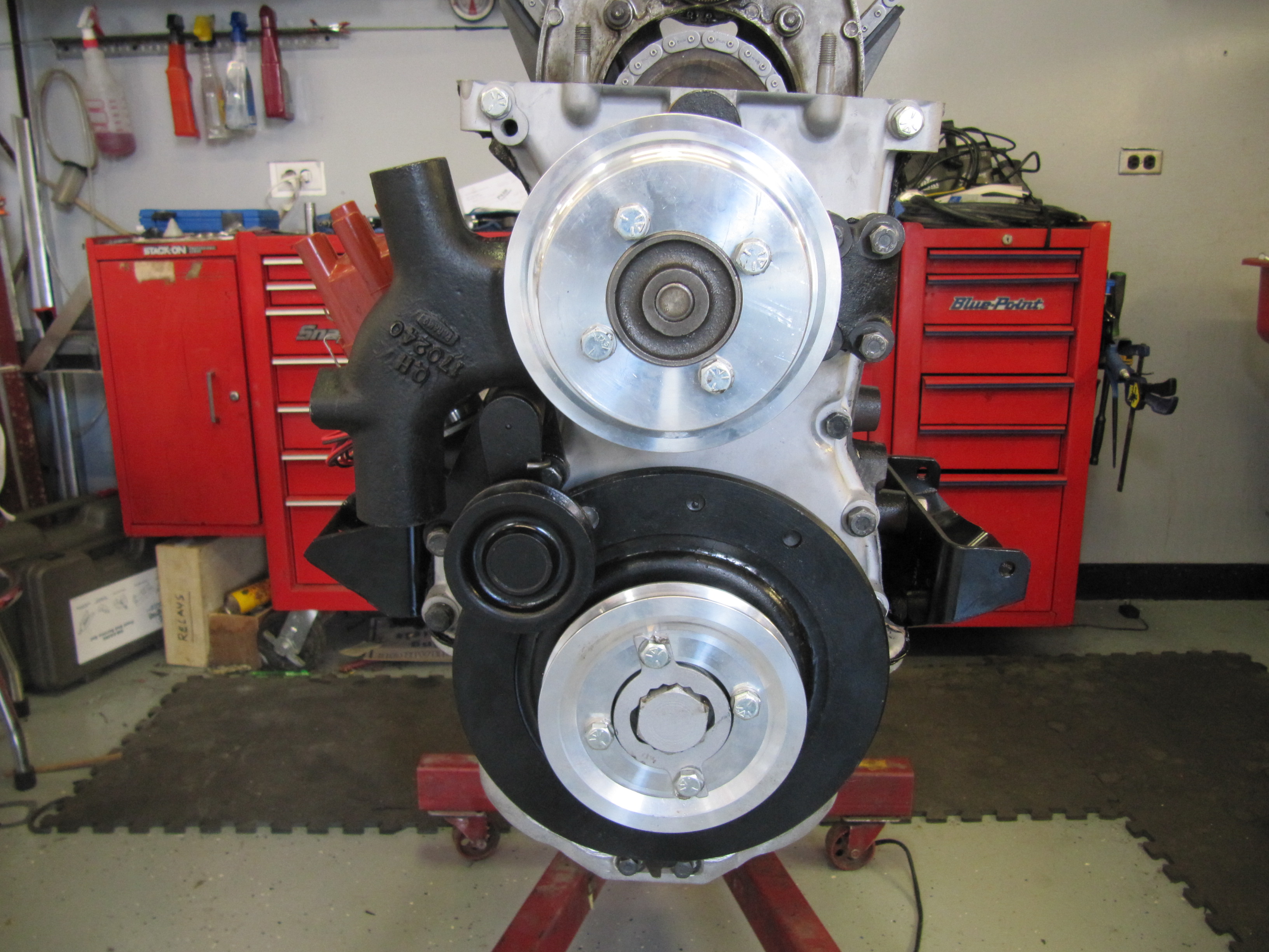
Front Engine Mounts
Upgraded engine mounts were ordered from SNG Barratt and were painted once received.
Upgraded Engine Mounts Painted
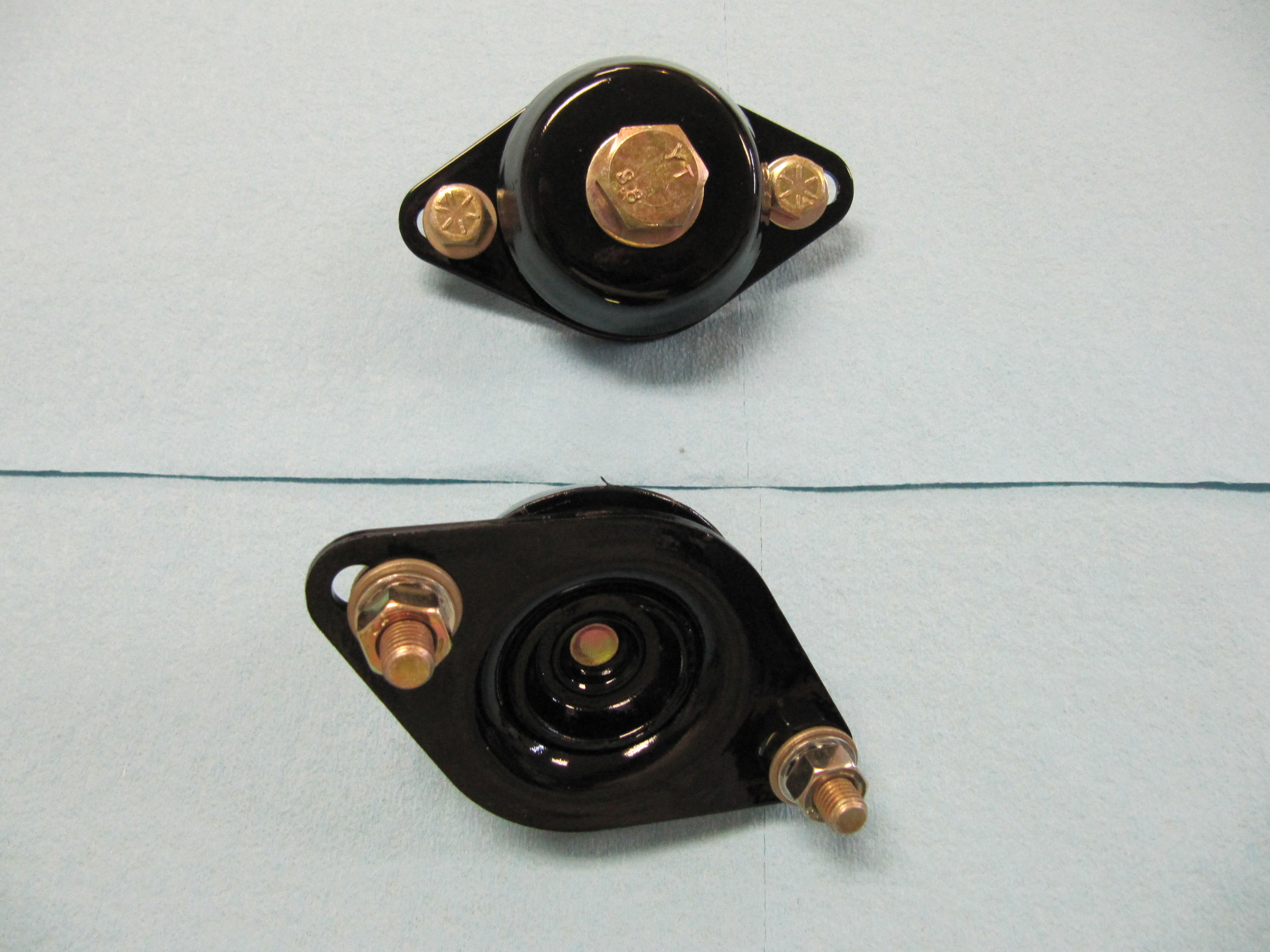
I wondered if the upgraded mounts were the same size as the original spec (but new) rubber mounts so I ordered a couple to see:
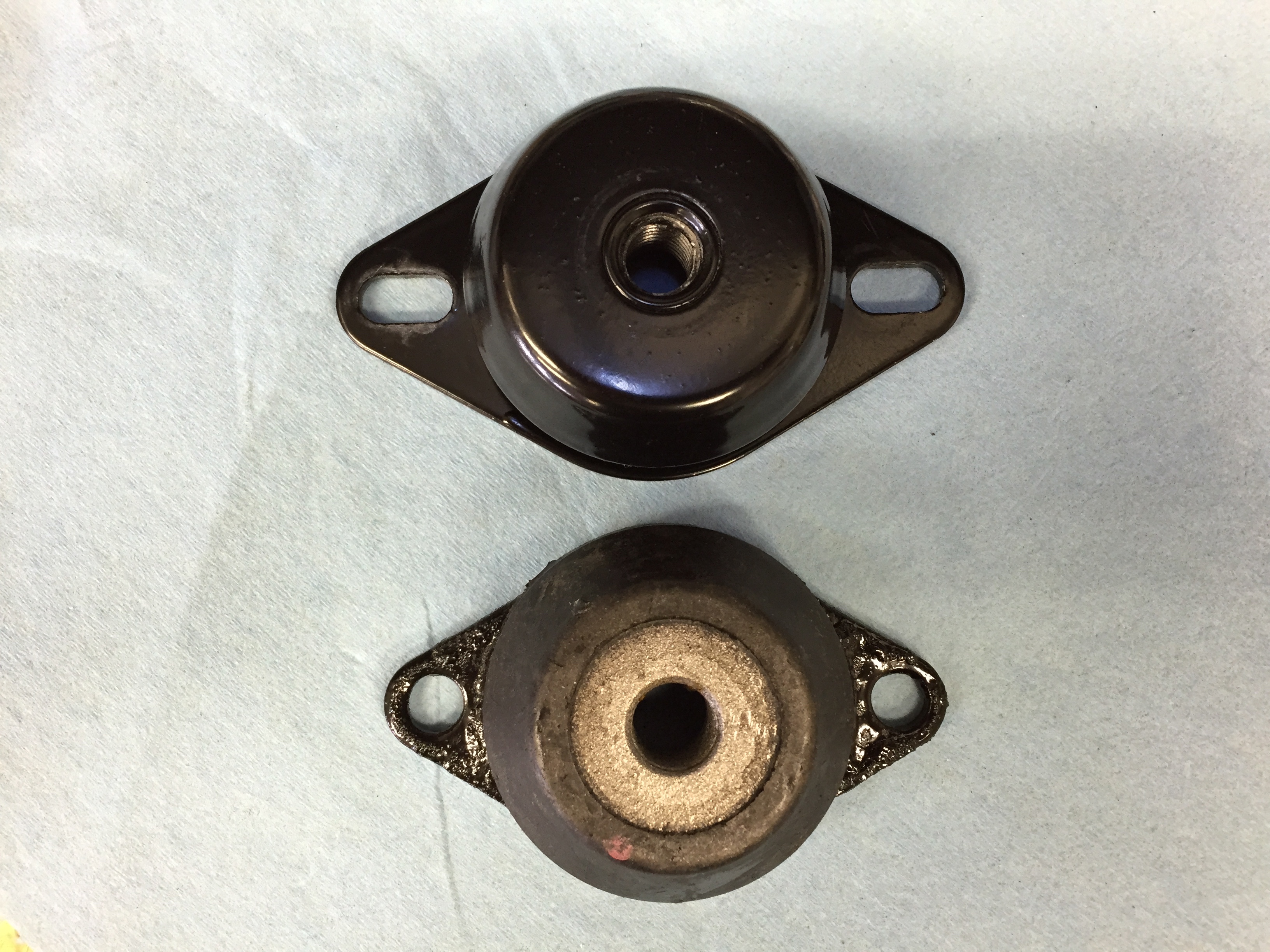
Upgrade Mount top and Original Spec Mount bottom
One can immediately see that the flange used to mount the rubber to the bracket is of a different shape and slightly wider, but it fits. Then to measure the height:
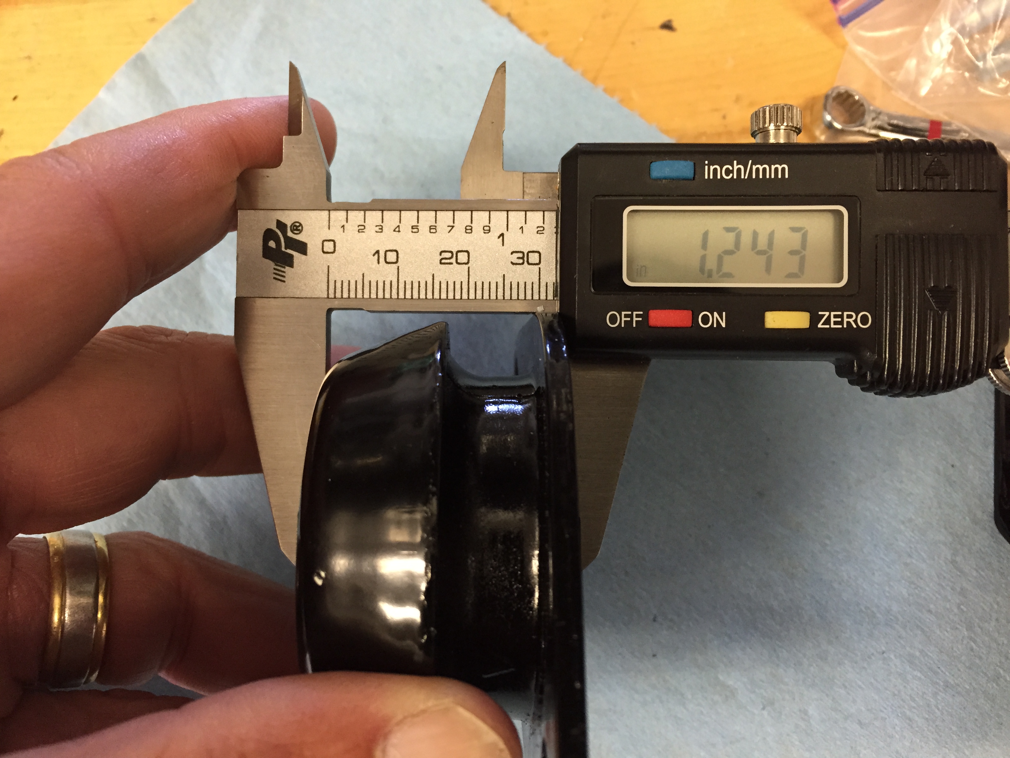
Upgraded Engine mount 1.243 inches High
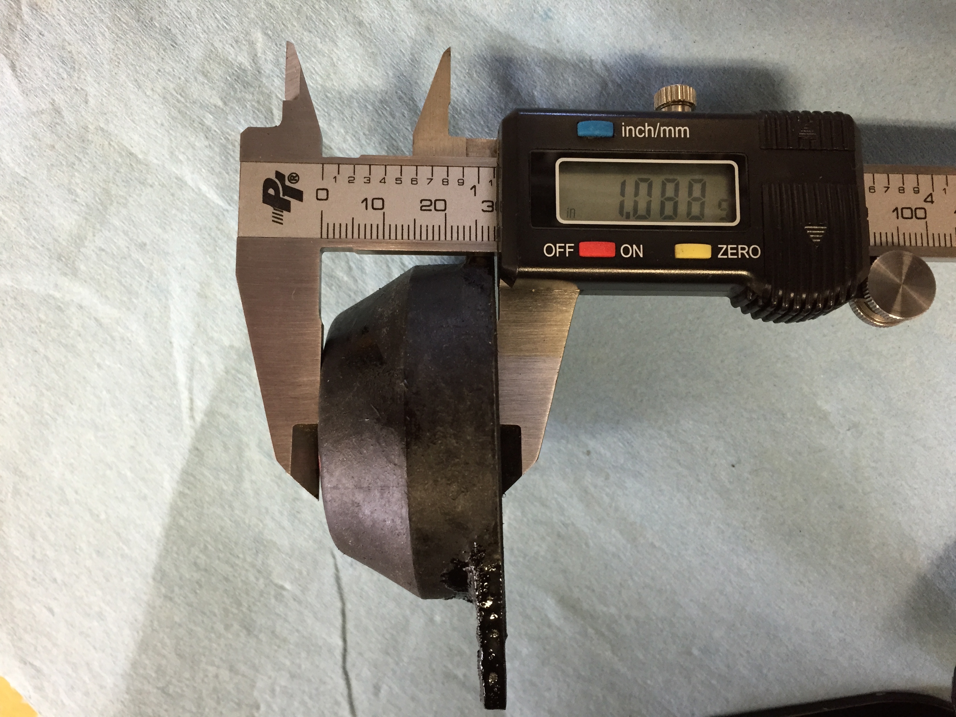
Original Spec Engine Mount 1.088 inches High
Hopefully this is not great enough difference to create a mounting problem. When I install the engine I will try the upgraded mounts first and see if they fit, but I have a fall-back if they do not.
This is an image of the both brackets and rubber mounts ready to go on the car. I have used Grade 8 fasteners throughout. The rubber mounts attach to the flange brackets with 5/16″-24 x 1″ hex bolts and I have used nylock nuts. The bolts used in the rubber mount are 1/2″-20 x 7/8″ with split and flat washers. The two long bolts in each flange assembly are 5/16″-24 x 3 3/4″ while the shorter bolts are 5/16″-24 x 3/4″ and each is secured with a nylock nut and flat washer. The assemblies were blasted and painted with POR-15.
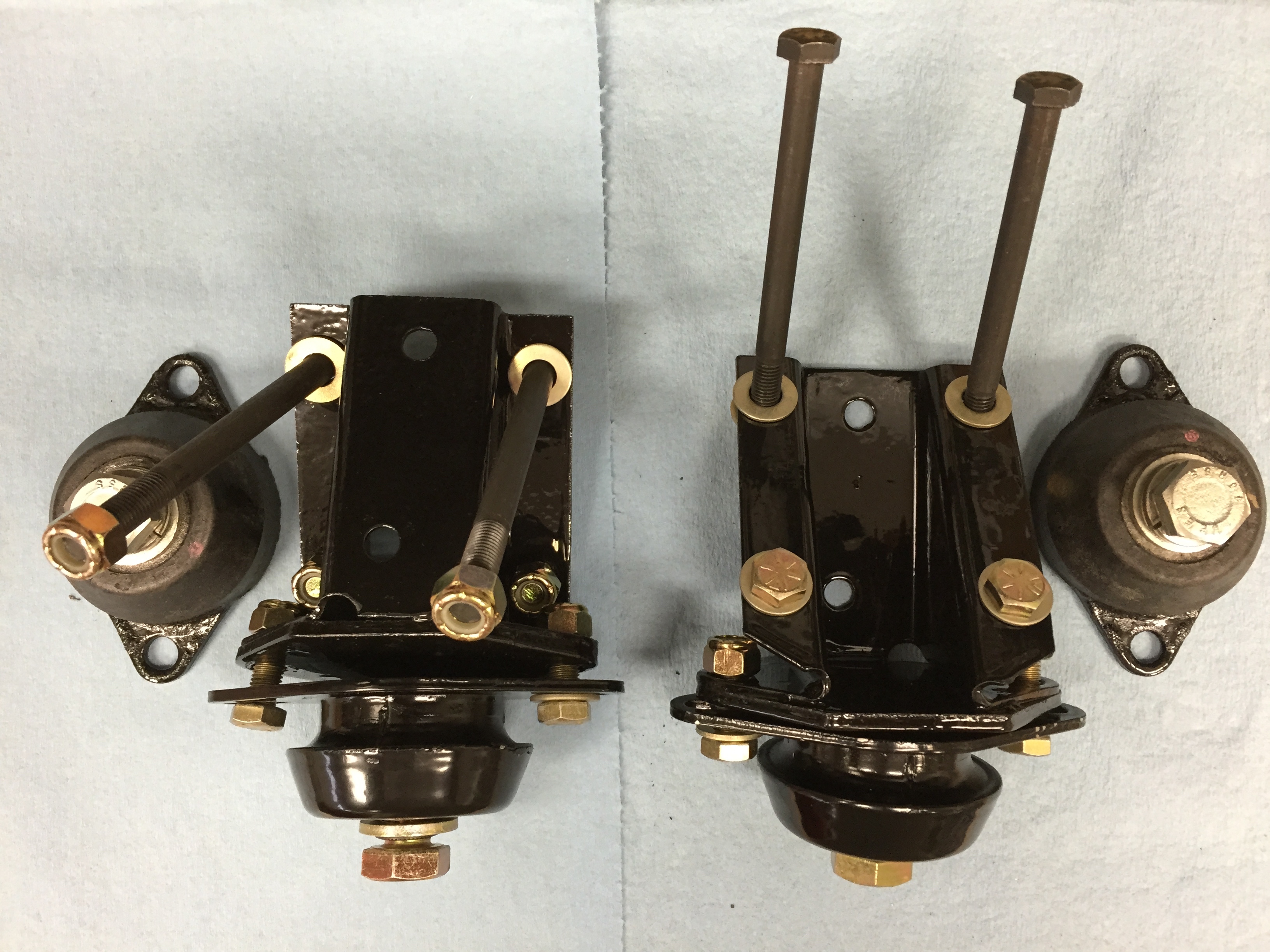
Bracket Assemblies with mounting rubbers and hardware
I am going to be installing the engine and gearbox before I complete bodywork and paint so I went ahead and installed the mounts to the car. I left the rubber mounts slightly loose as there is a little adjustability for mating with the engine. I will tighten after the engine is installed.
RH Motor Mounts Installed
LH Motor Mounts Installed
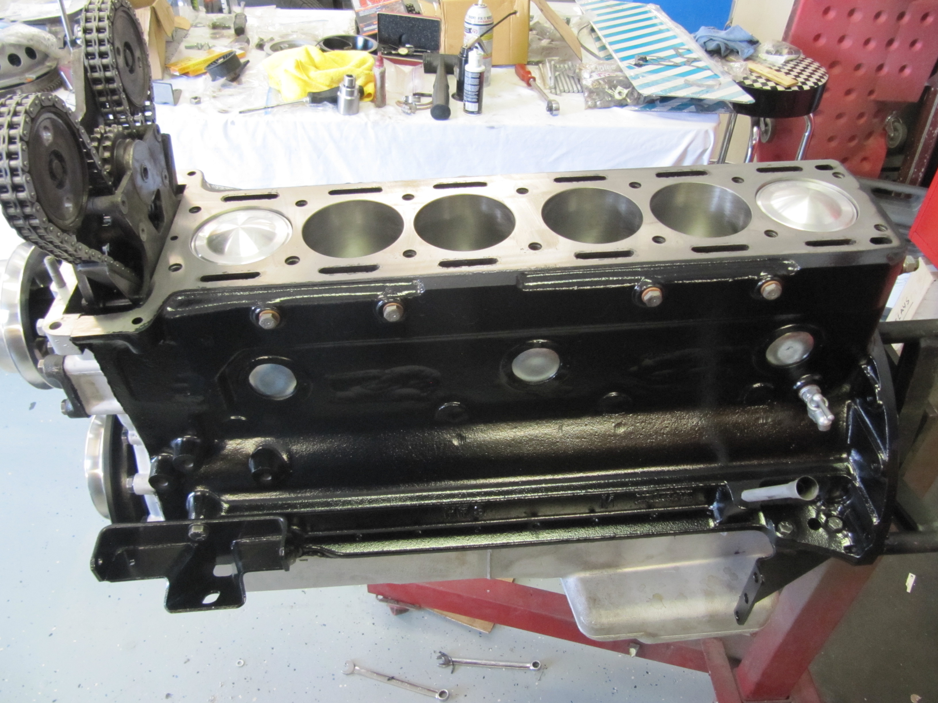
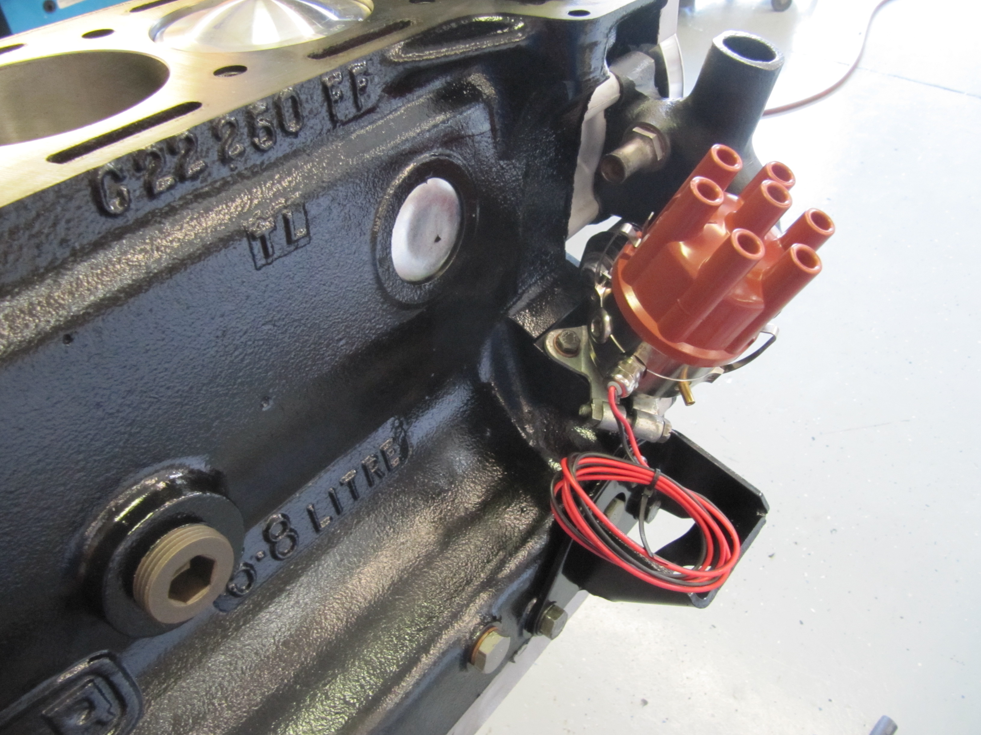
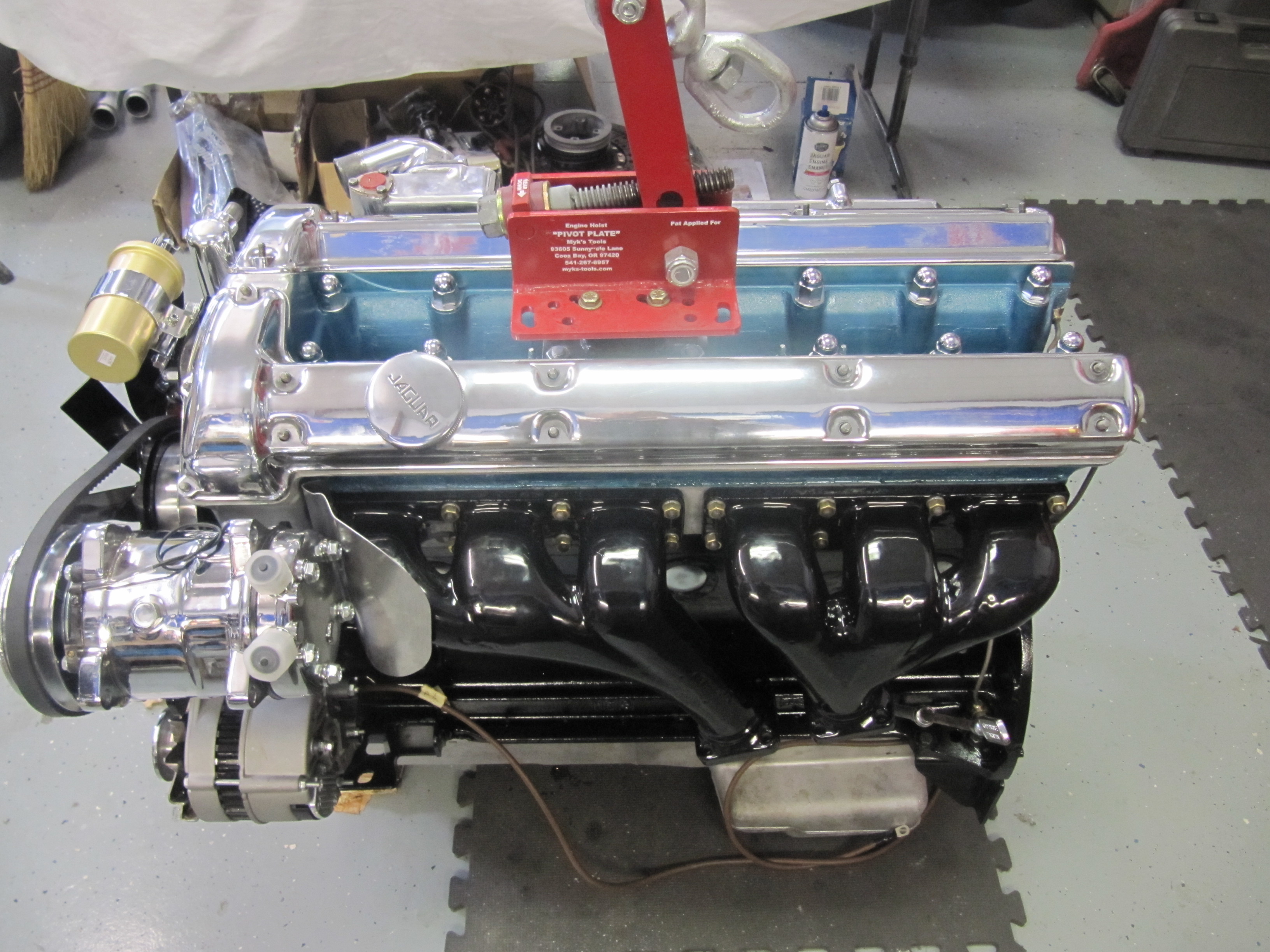
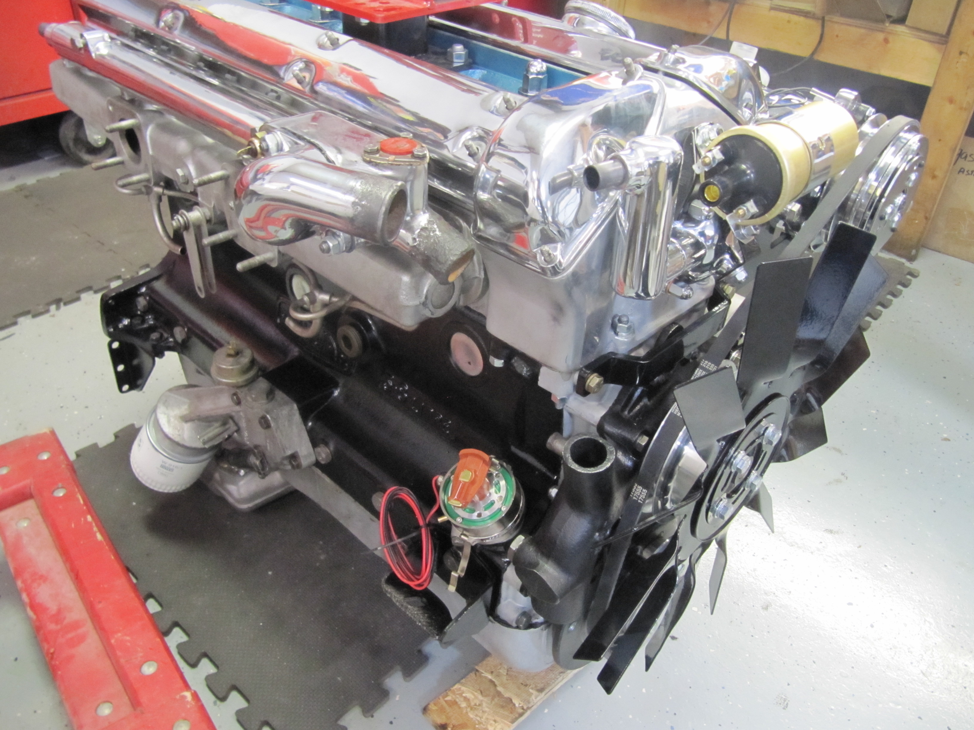
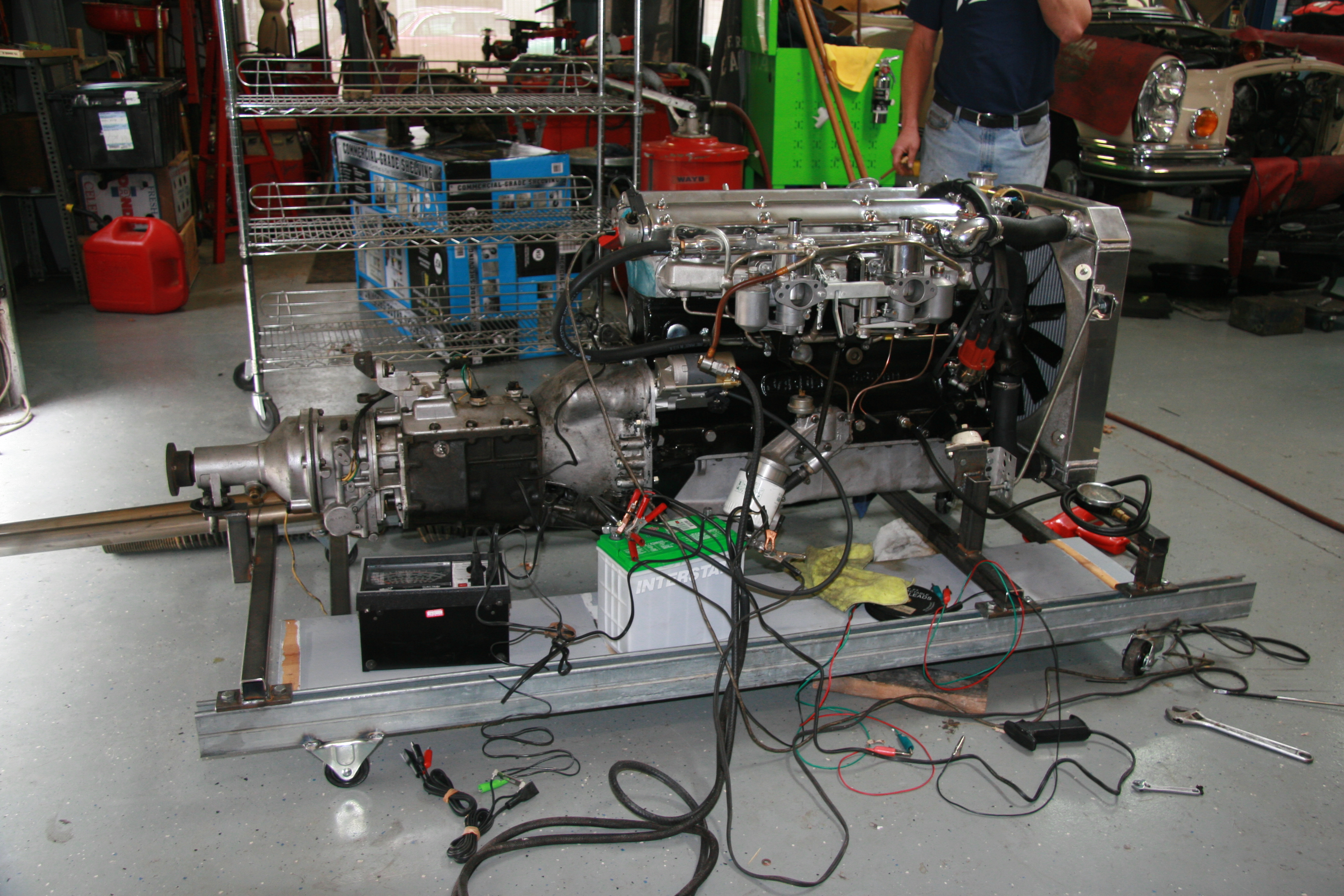
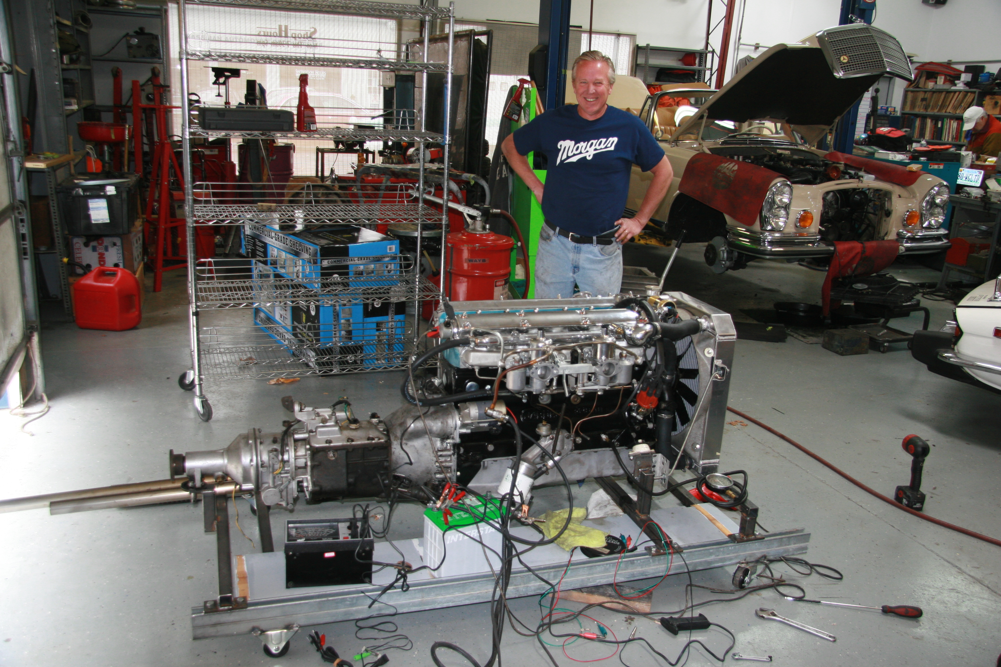
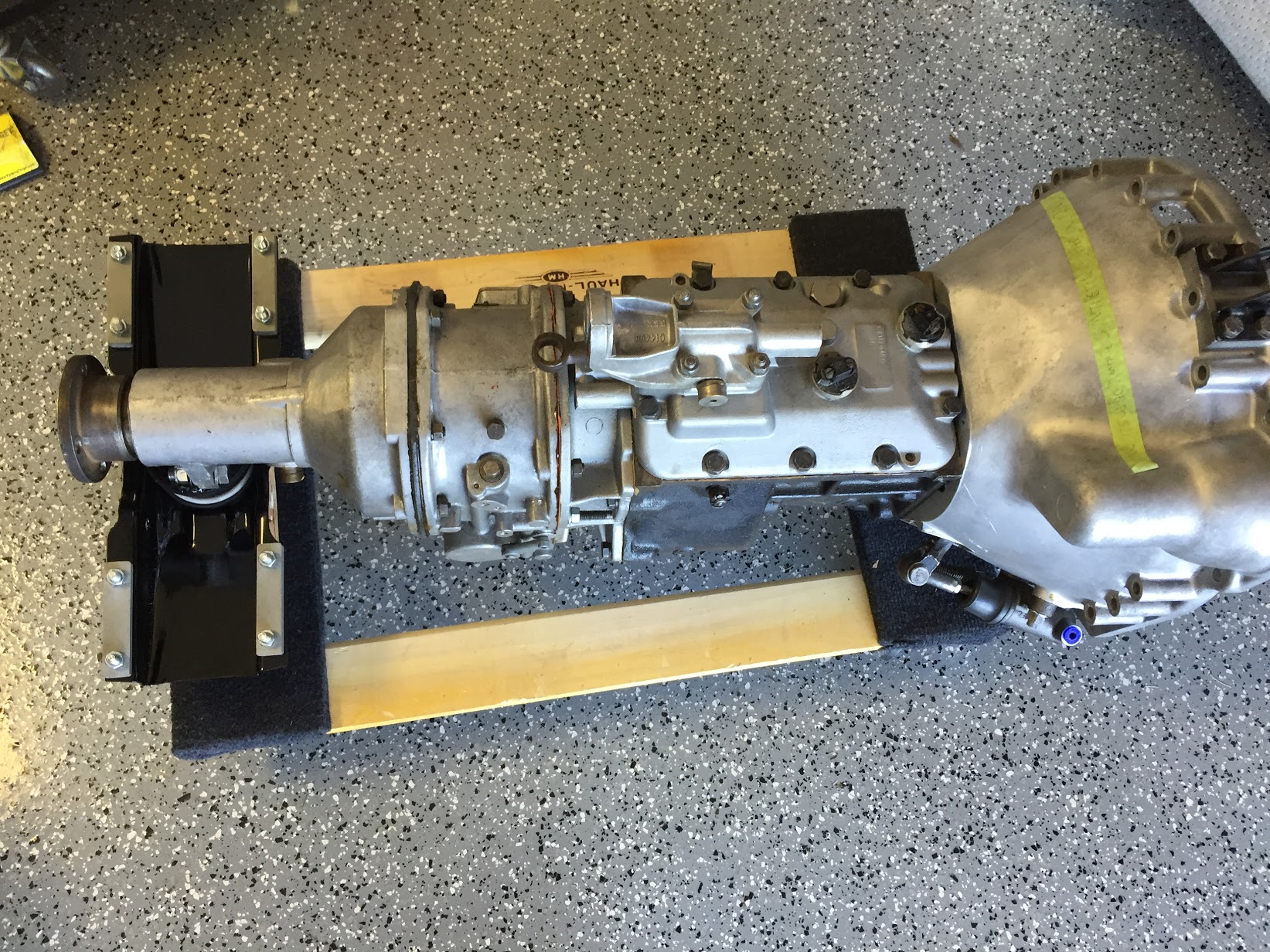
The Trial Engine Install
As mentioned in other posts under the “Restoration” heading of this site, my plan is to install the engine/gearbox, electrical system, front and rear suspension and etc. so that I can test and run the major systems before I paint the car. So…. after getting everything in and tested I will then pull it all out, do the bodywork and paint and then reassemble. Crazy I know, but then no surprises after the car is painted.
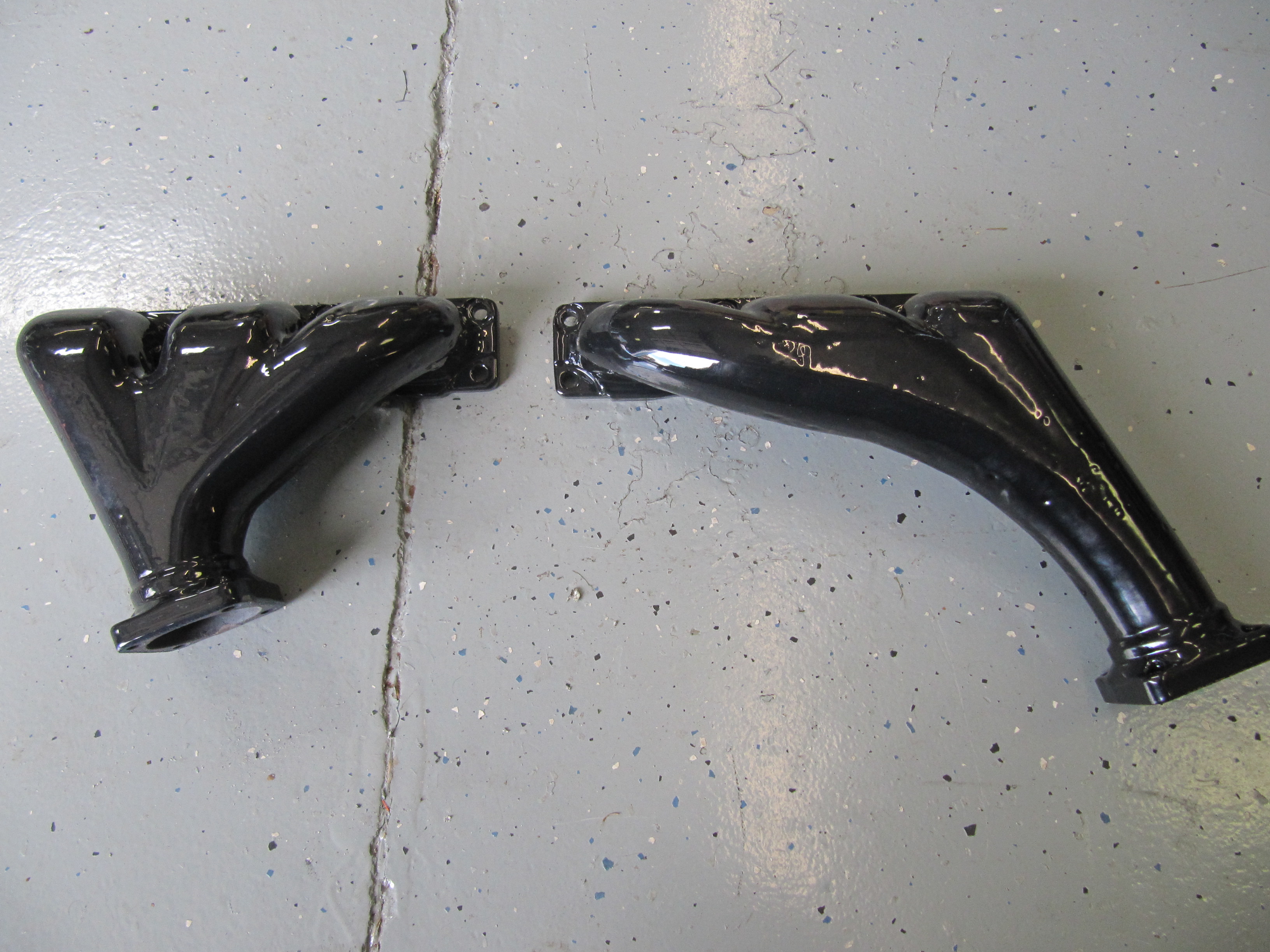
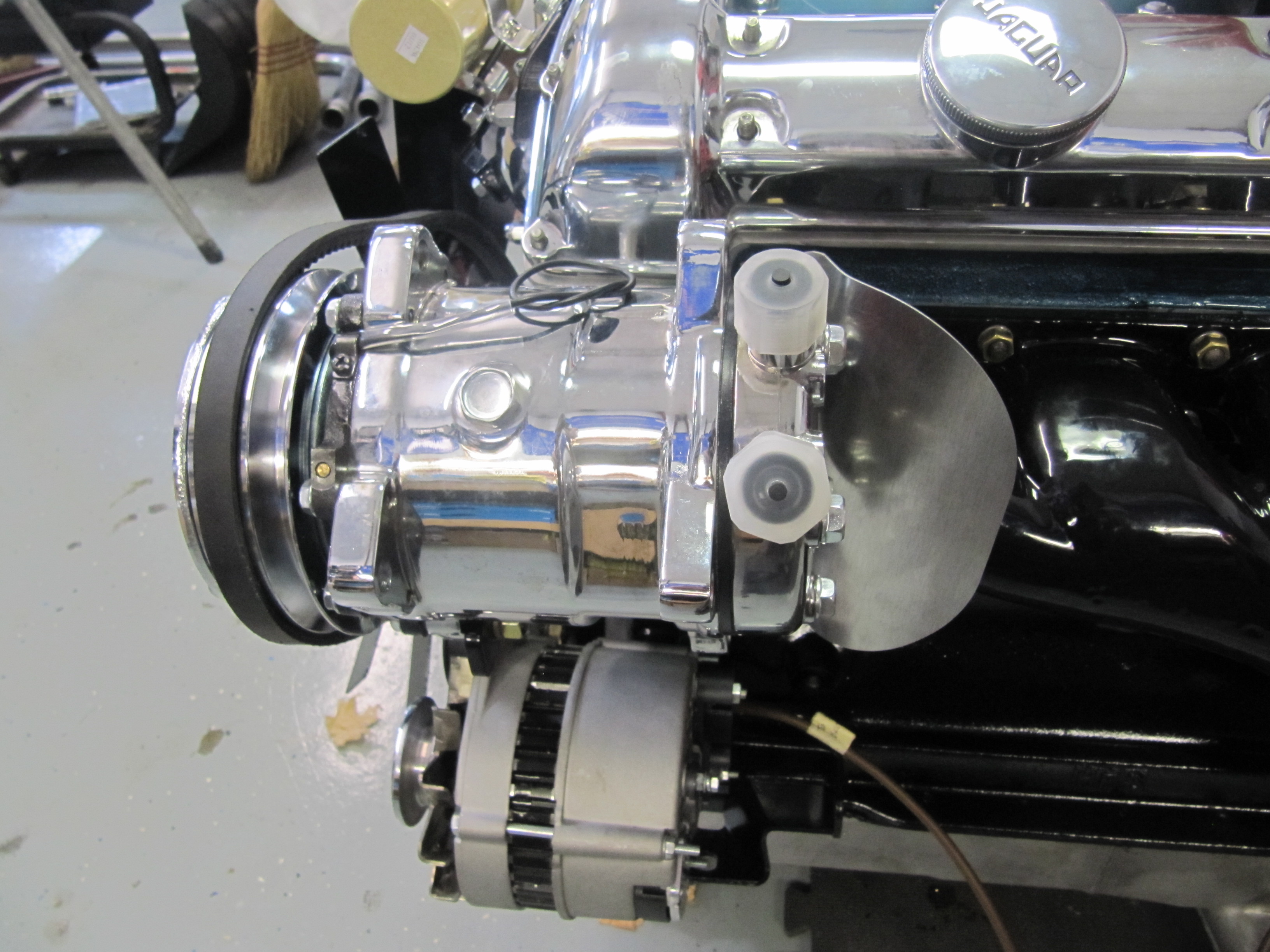
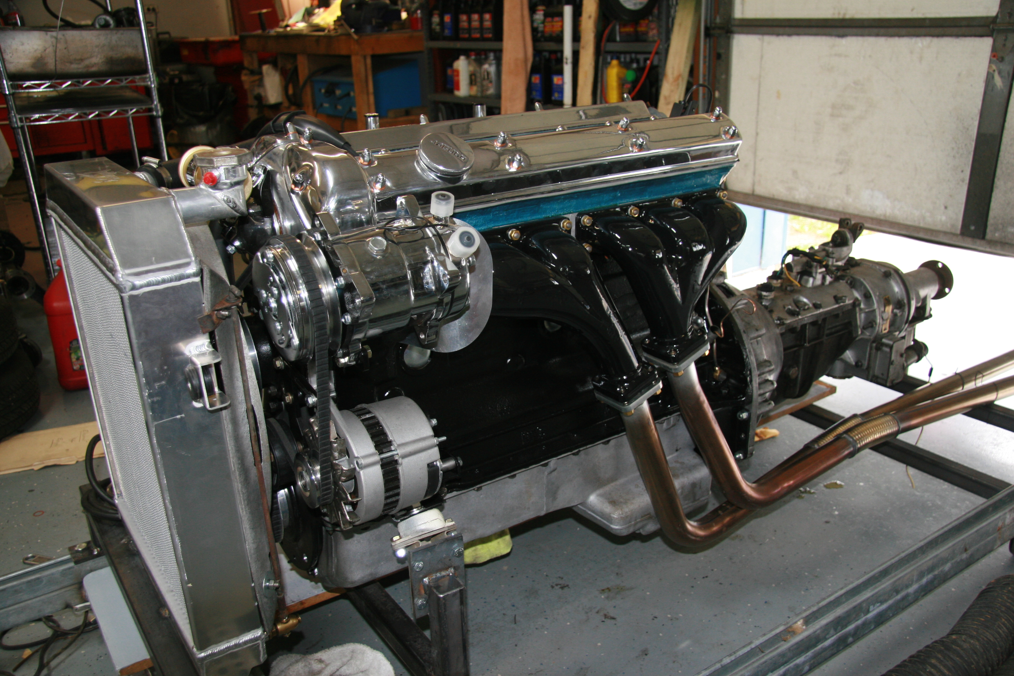
Here is a short video I made of the install of the rebuilt engine. I used my lift to lower the car over the engine. You will note that I removed the LH engine mount and the exhaust manifolds – just to protect them since they have an expensive new porcelain coating now. On the RH side of the engine I removed the carburetors and their linkage, but left the oil filter and starter.
In a separate entry “Engine Post-Installation Check List” I will detail all of the connections and other items that must be tended to prior to starting the installed engine.
When I do this the final time and at the suggestion of a buddy and advisor, John Stefanik, I will leave the LH mount as well as the alternator and air conditioner compressor/mount and remove the RH mount and the oil filter. The alternator and compressor are not easy to mount once the engine is in the car. We will see. Anyway, here is my install video. Thanks to my wife and grandson for their assistance!