Blog Posts:
12/24/2021 – REAR DIFFERENTIAL SEAL REPLACEMENT AND DRIVESHAFT INSPECTION
12/22/2021 – EMISSIONS SYSTEM CHARCOAL CANISTER INSPECTION AND HOSE REPLACEMENT
12/20/2021 – ALFA ENGINE OIL, FILTER AND AIR FILTER CHANGE
12/15/2021 – FUEL TANK, FUEL HOSE, FUEL FILTER, FUEL PRESSURE REGULATOR REPLACEMENT
10/07/2021 – SIGNIFICANT FUEL LEAK AT COLD START INJECTOR
04/28/2021 – DOOR SEAL AND RH DOOR CAP REPLACEMENT
04/13/2021 – VACUUM HOSE AND HOSE CLAMP REPLACEMENT
05/05/2021 – RADIATOR REPLACEMENT
03/22/2021 – A NEW AND HOME MADE OIL VAPOR SEPARATOR
2/15/2021 – HANDBRAKE ADJUSTMENT AND PARTS, DOOR BUFFERS, AND POWER MIRROR SWITCH
01/31/2021 – ALFIE RELOCATION
07/10/2017 – IGNITION REFRESH
December 24, 2021
70,900 miles on the odometer
REAR DIFFERENTIAL SEAL REPLACEMENT AND DRIVESHAFT INSPECTION
The rear diff seal has been leaking for some time. So, it was time to dig in and replace it. The driveshaft was also pretty rusty and it since I have to disconnect it from the differential I decided to go ahead and remove it to paint it and inspect the universal joints.

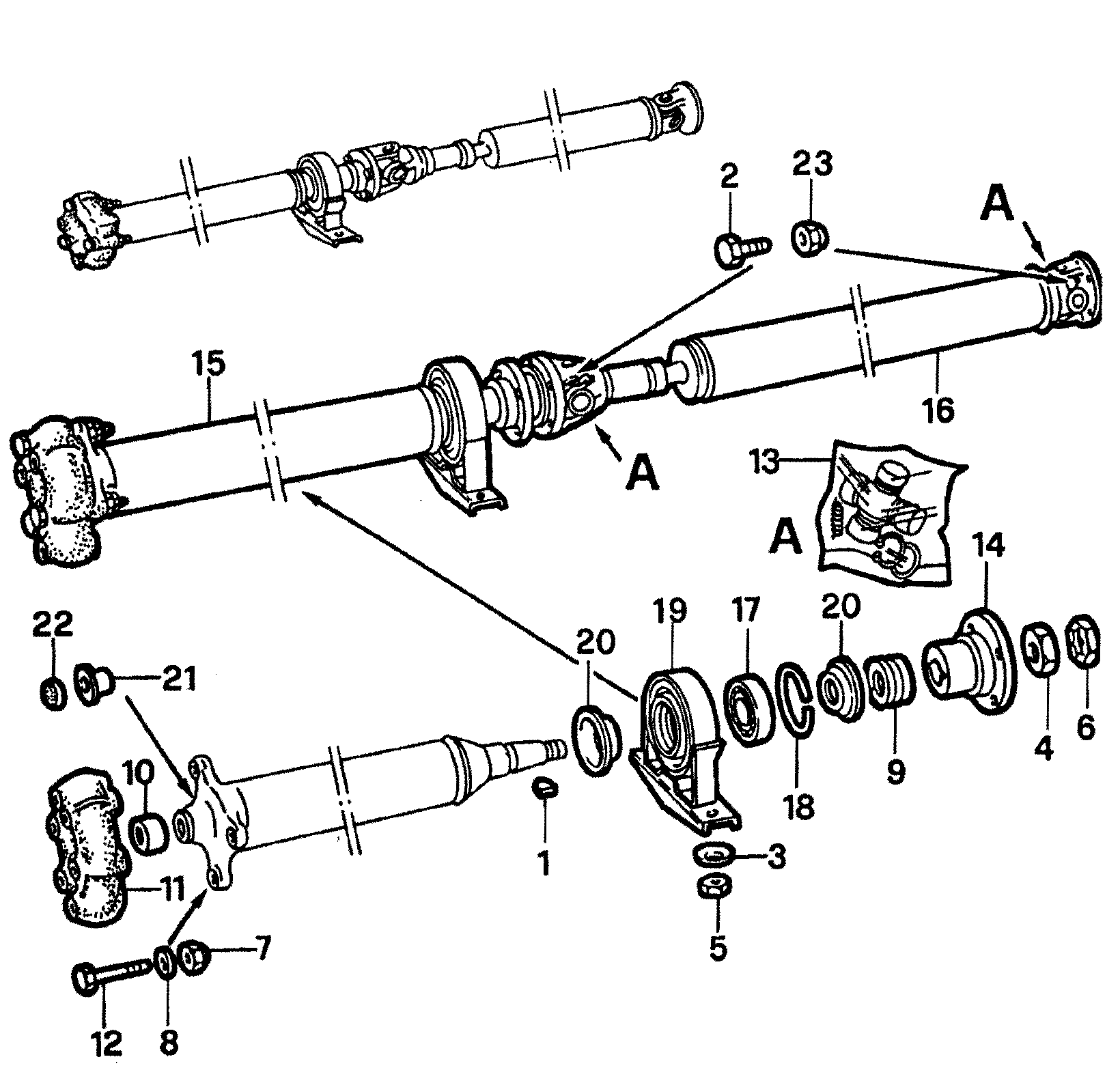
Alfa 105 Driveshaft
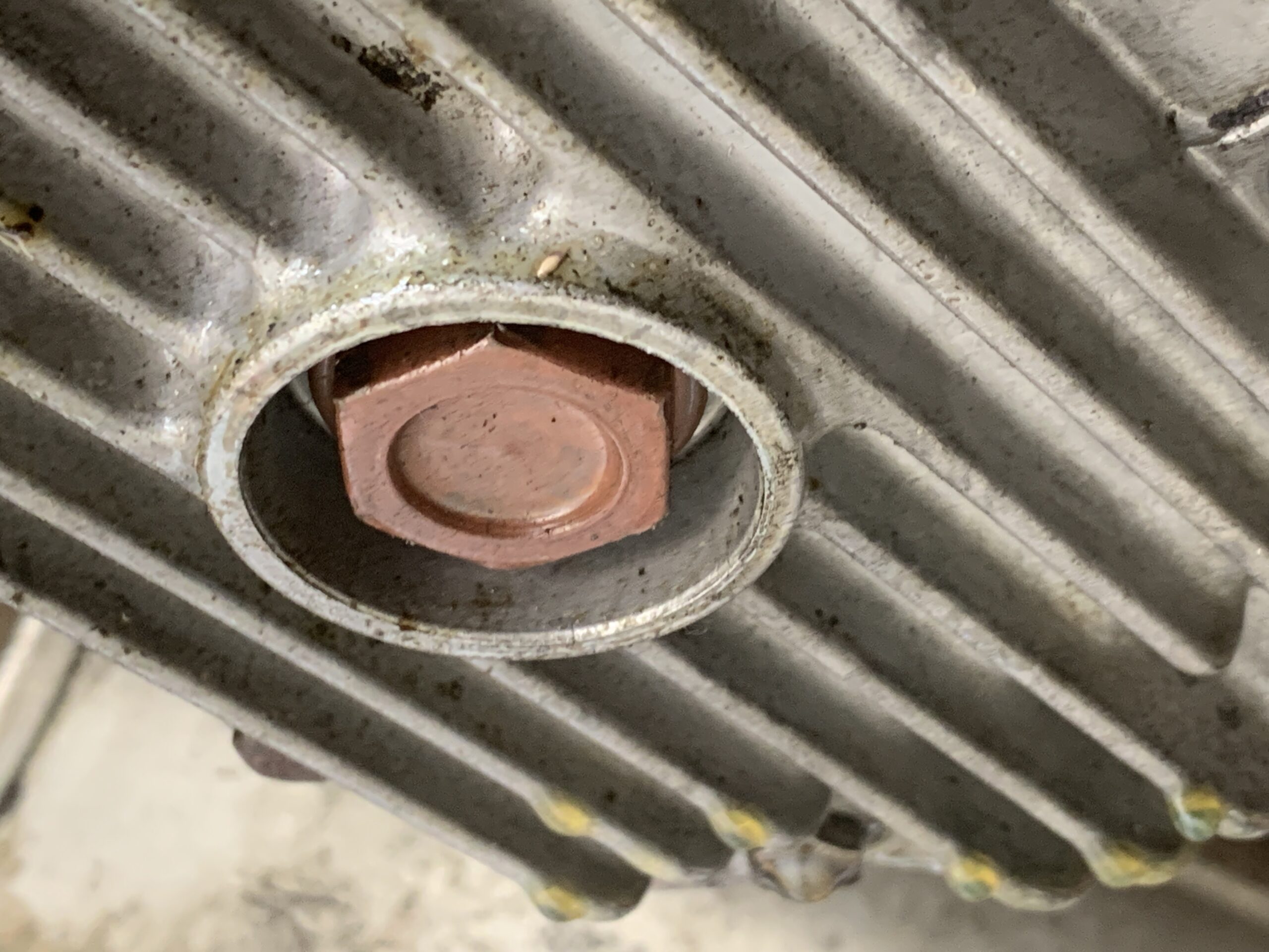
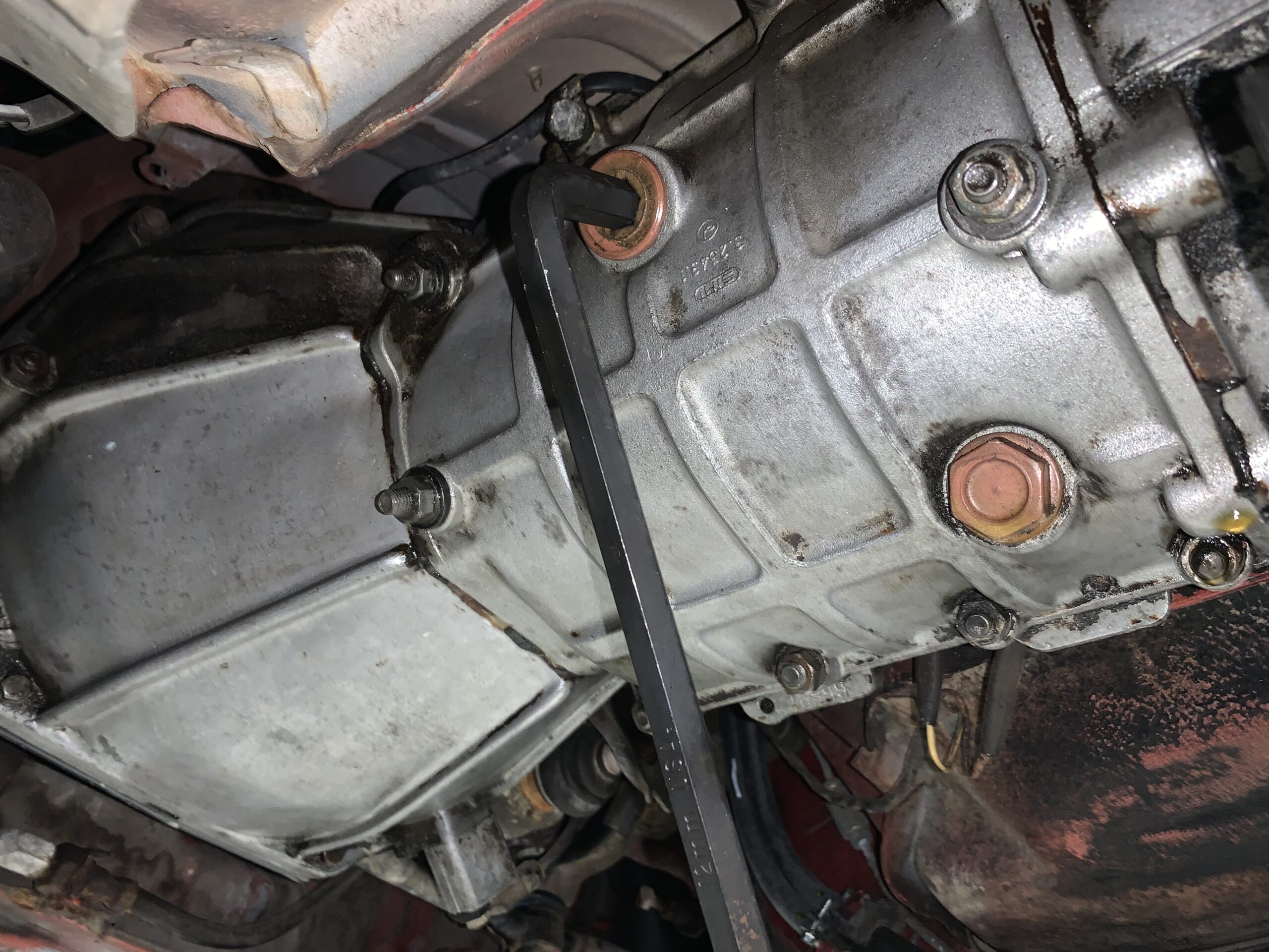
The first step was to drain the gear oil from the differential. The fill nut which you always open first is a 12 mm hex fitting. The drain plug is a 23 mm nut – I used a 7/8” wrench.
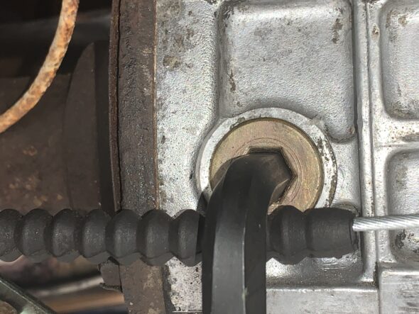
Rear Differential Filler Nut
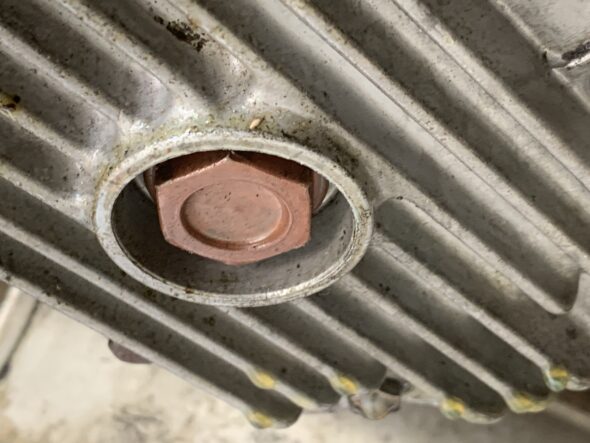
Rear Differential Drain Plug
I then marked the alignment of the driveshaft at both ends so that it can be reassembled in the same relative position.
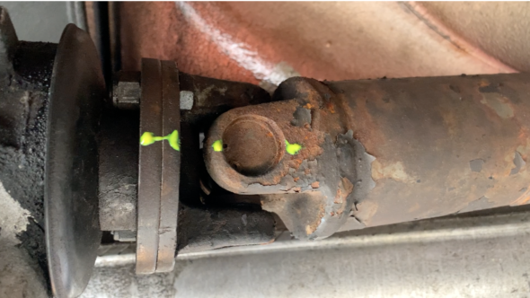
Marking Driveshaft for Removal
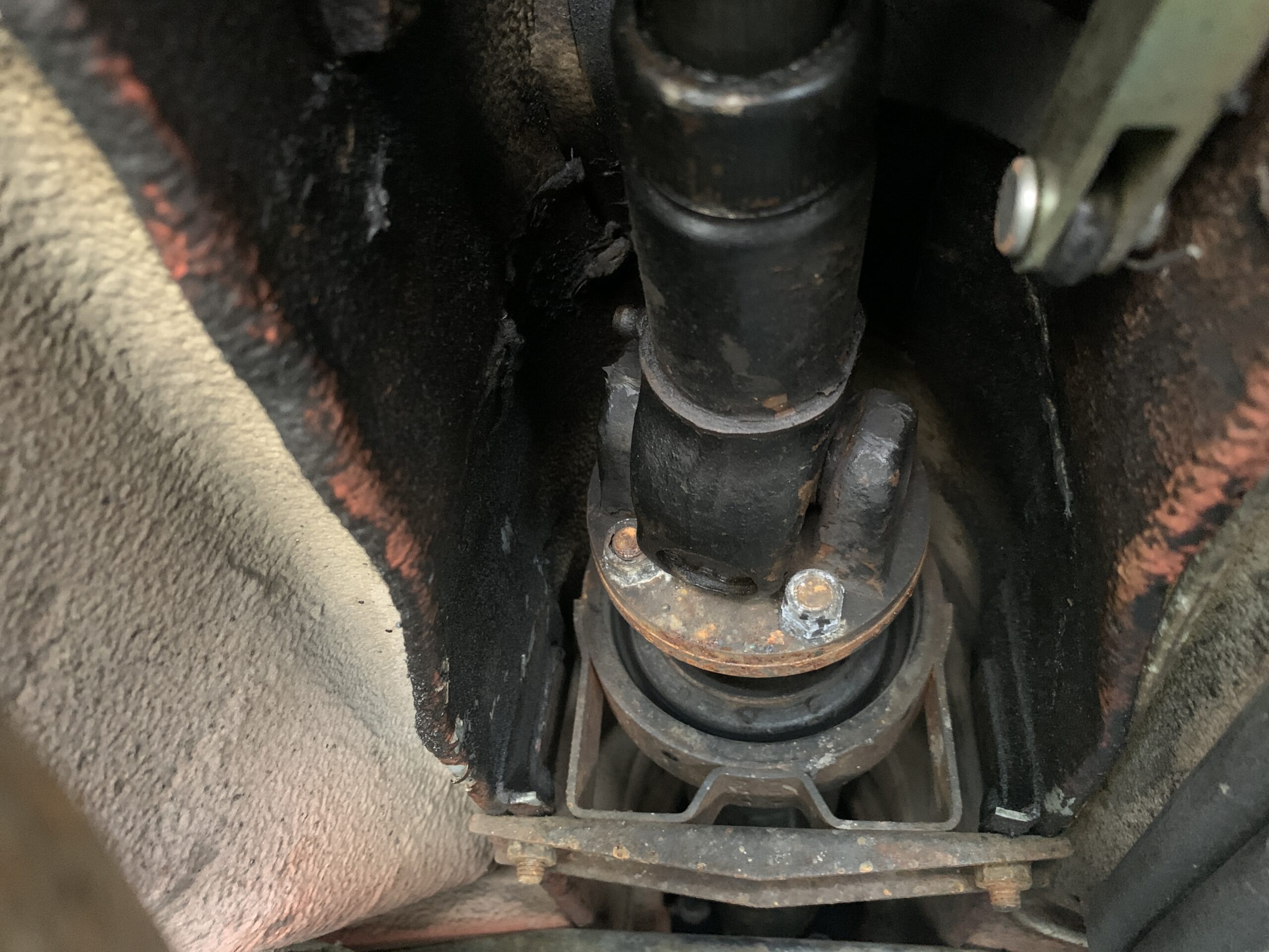
The nuts and bolts used at both ends of the driveshaft are an odd size – 9mm, and are a little hard to get a wrench on. The heads on a few of the bolts were rounded on the corners so I ordered four extras and eight new nuts from Classic Alfa. One trick I read about it to grind down the end of an open end wrench so that it will bottom out on the bolt head. I may try that upon reassembly. I also have a thin wall socket that may be useful. The bolts and nuts require a 13mm wrench/socket.
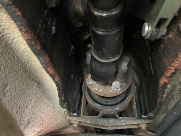
Driveshaft at the Center Support Bearing Carrier
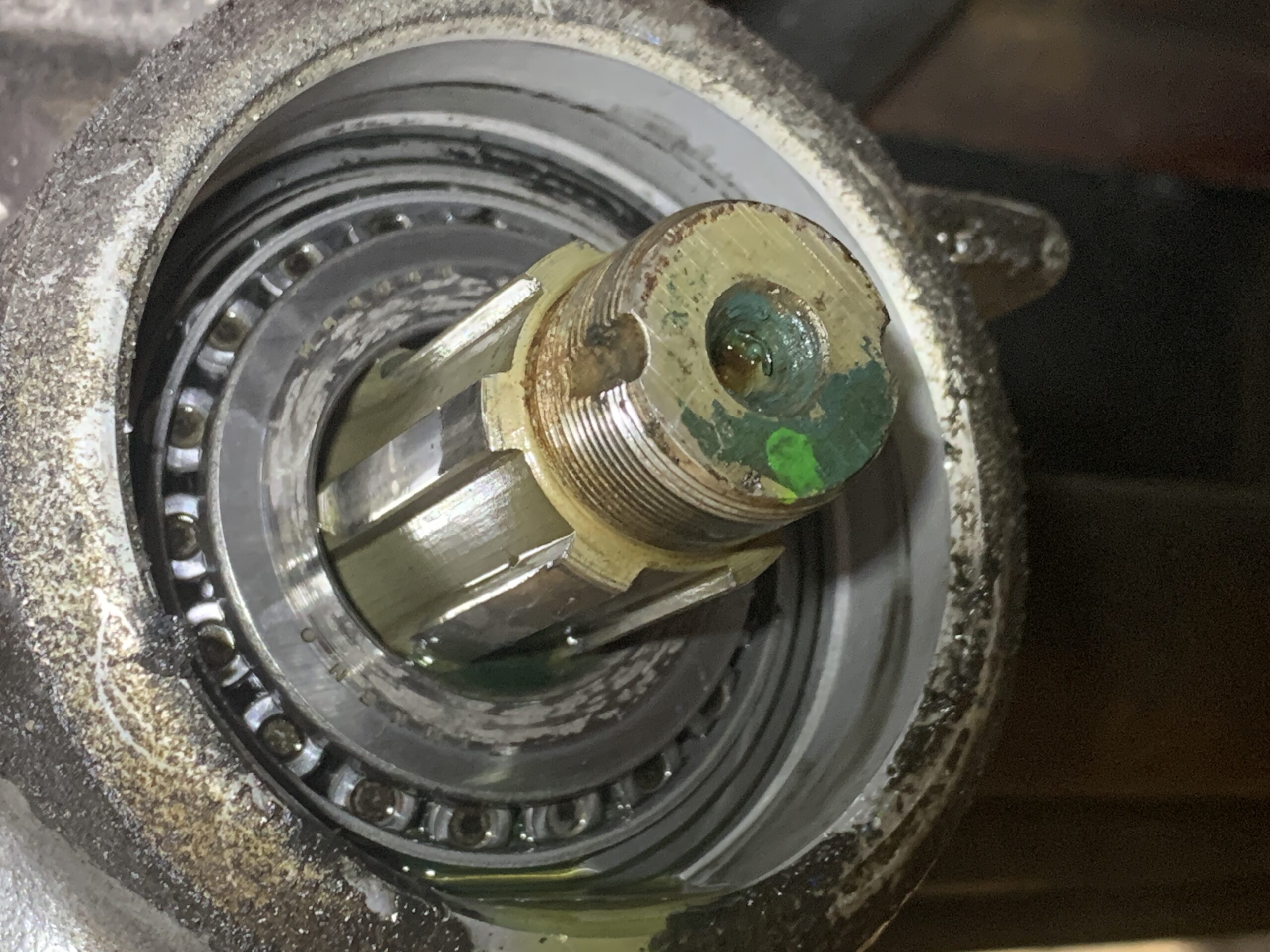
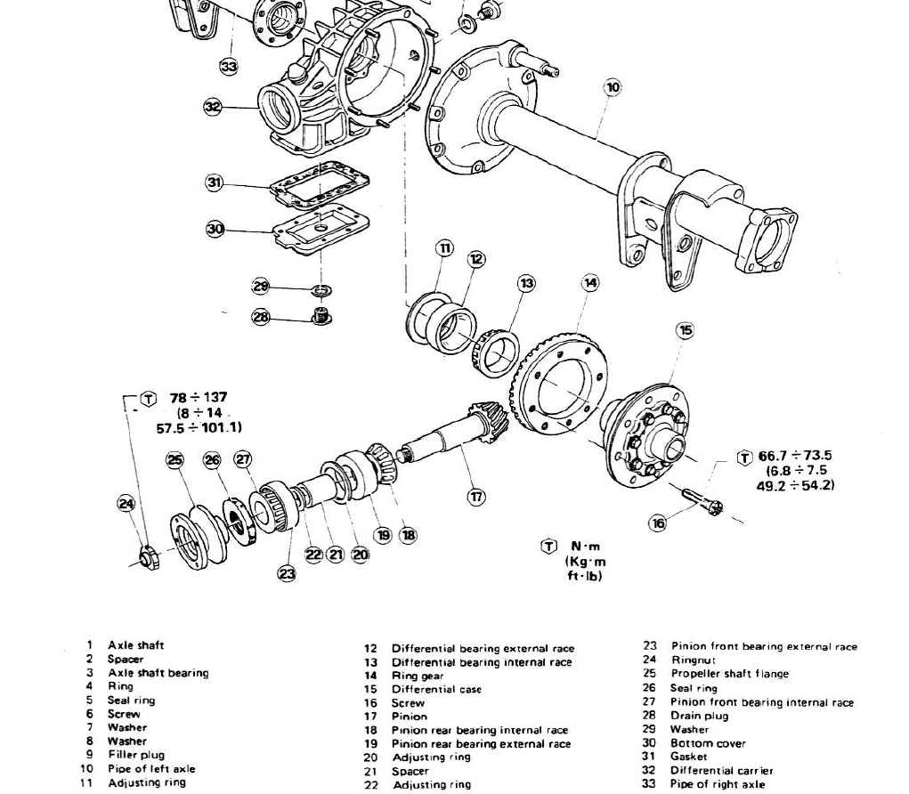
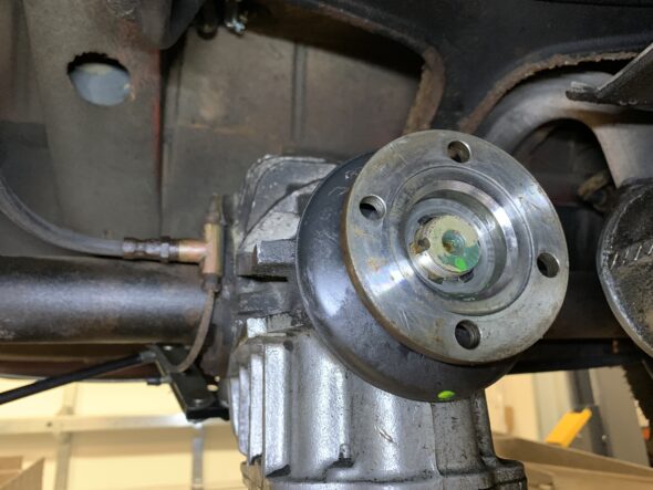
After removing the driveshaft this is what the pinion look like:
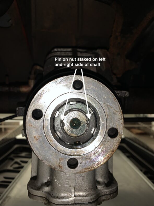
Rear Differential Pinion Nut
Where the staked indents are made, sometimes it is possible to bend the nut flange back into shape before removing, but I was not successful with that and the small sections of the flange broke when I loosened the nut. I have a new replacement sourced from Classic Alfa. The replacement torque on this nut is Important because one does not want to create drag on the free movement of the axles. Unfortunately, I didn’t read it until after I removed the nut, but one should note the position of the nut on the shaft and count the number of exposed threads so that the new nut can be returned to the same position. It has been suggested that it should be okay to just replace the nut and torque it to 75 ft. lbs. so I will try that method.
After marking the relative location of the pinion nut and the pinion shaft, I remove the pinion nut with a breaker bar in special socket.
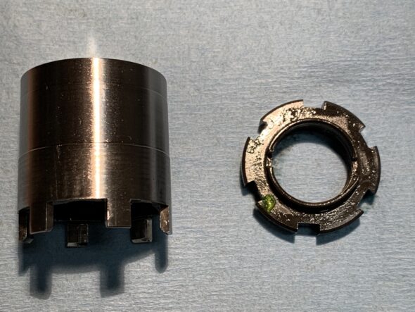
Differential Nut and Special tool for its Removal
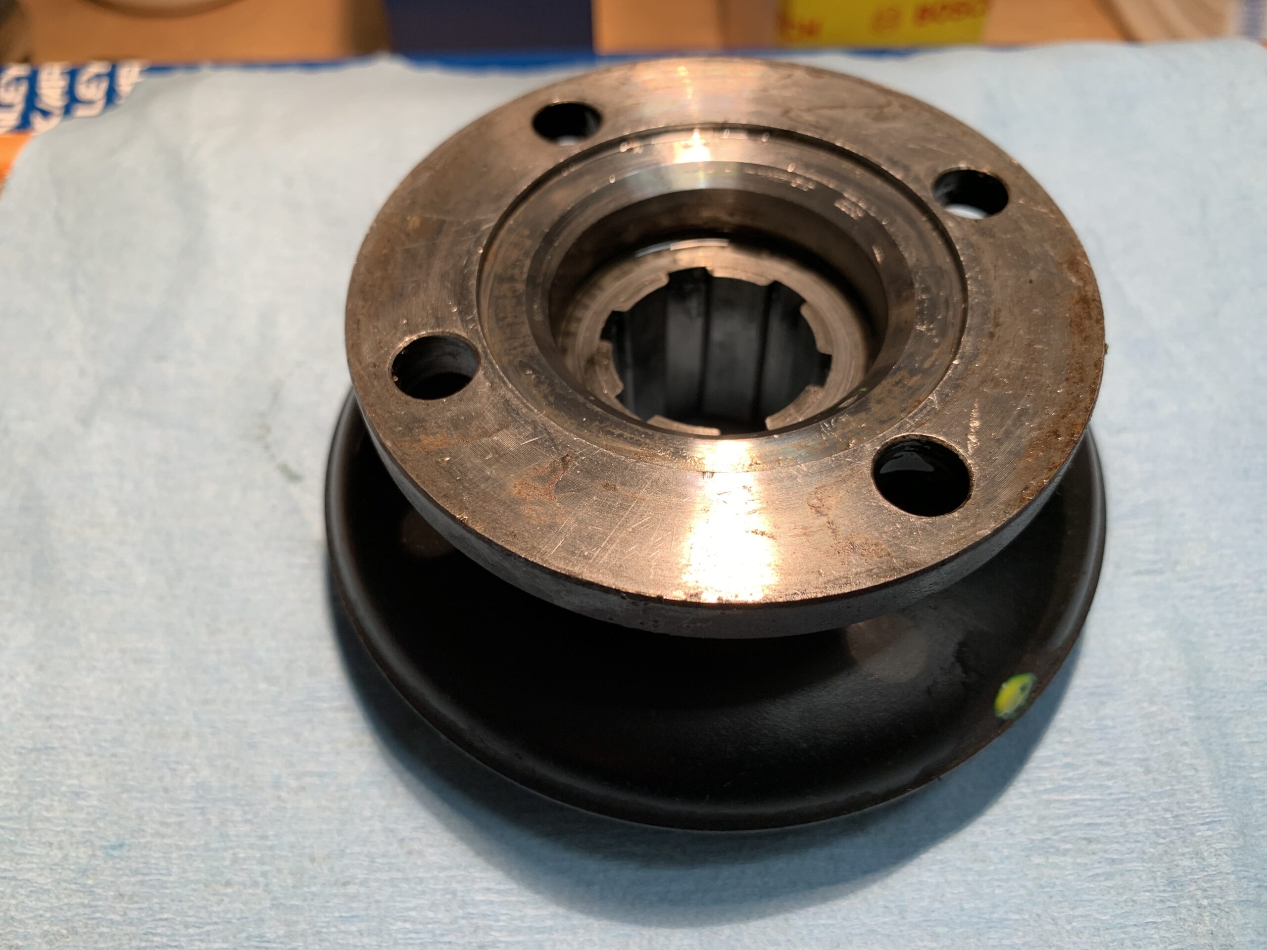
It is sometimes reported that the flange is difficult to remove, possibly requiring a puller; however mine pulled off the shaft by hand. After marking it was removed.
Differential Pinion Shaft Nut Removed

Rear Differential Pinion Flange Removed
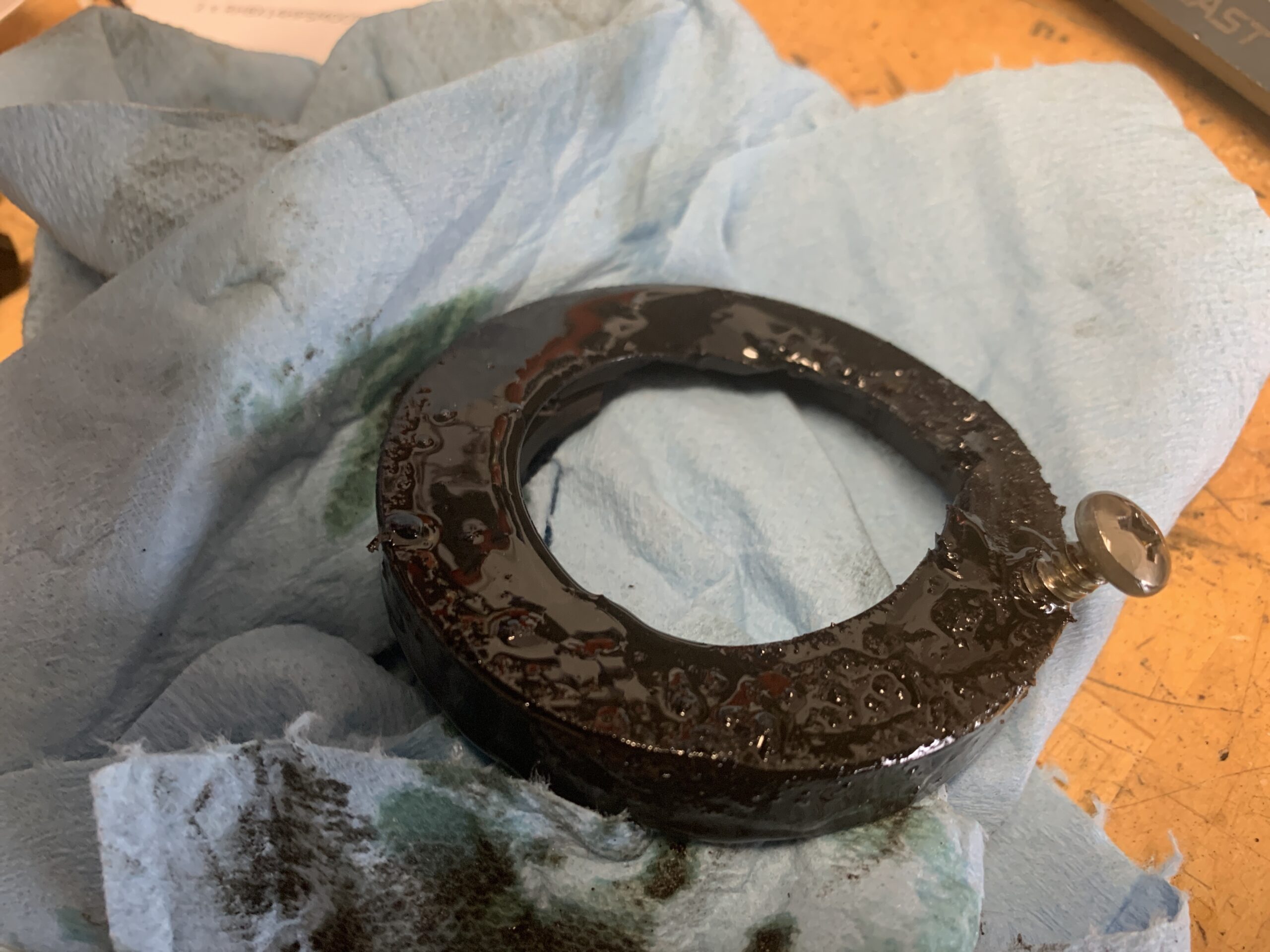
To pull the seal out I first tried to drill a small hole in the seal close to the edge to catch the metal in the seal, insert a self tapping screw, and then pull the seal out with the screw and a claw hammer. Worked like a charm. Just need to be careful to avoid scratching the housing when drilling and inserting the screw.

Rear Differential Pinion Seal Removed

Rear Differential Pinion Seal Removed with Bearing Exposed
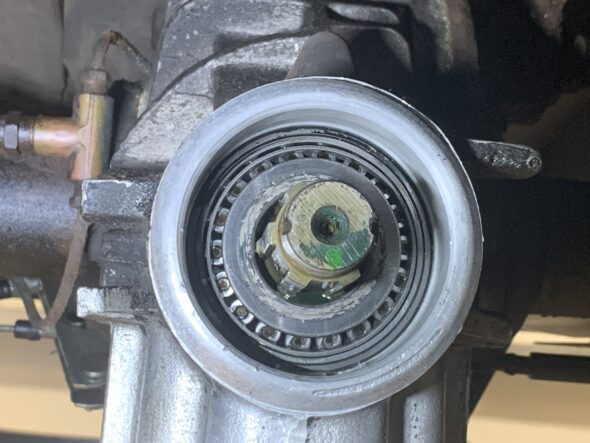
Cleaned and Ready for New Seal
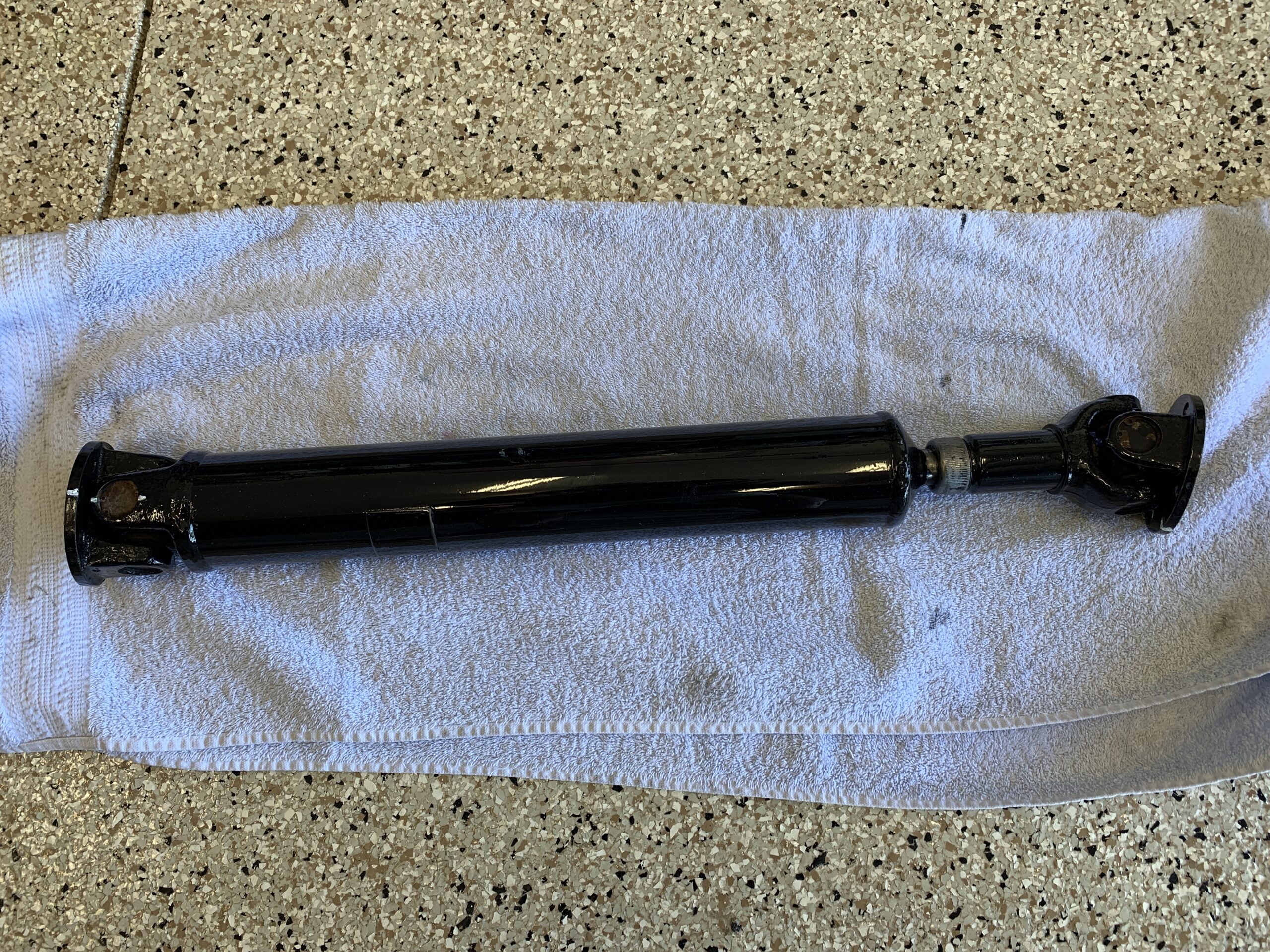
In the meantime, I cleaned, wire brushed, sanded and painted, with POR 15, the rear driveshaft and have it looking really nice.
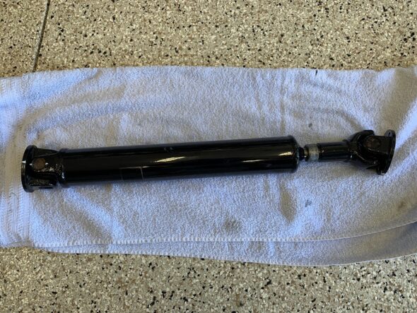
Rear Driveshaft Cleaned and Painted
A few notes for reinstalling the diff seal and flange and nut. PapaJam – Torqueing the pinion nut to the 58-101 lb/ft spec may result in the pinion locking up solid. You want to able to turn the pinion by hand with only a little bit of resistance. Another source said 72.3 – 101. Jim G said – I’ve always done them to around 75. Which usually ended up being a little after the original stake marks.Some people use blue Loctite on the nut.
December 22, 2021
70,900 miles on the odometer
EMISSIONS SYSTEM CHARCOAL CANISTER INSPECTION AND HOSE REPLACEMENT
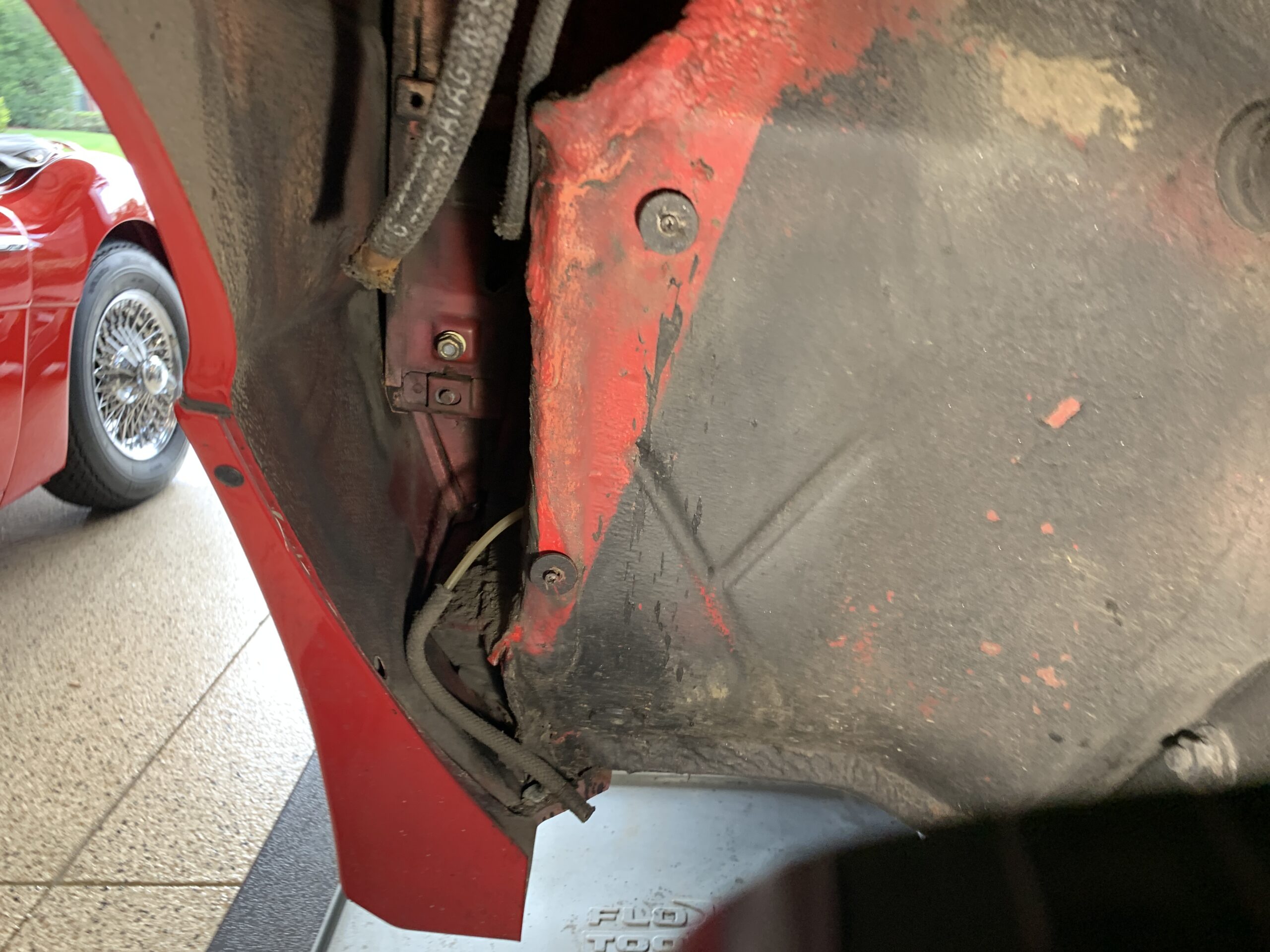
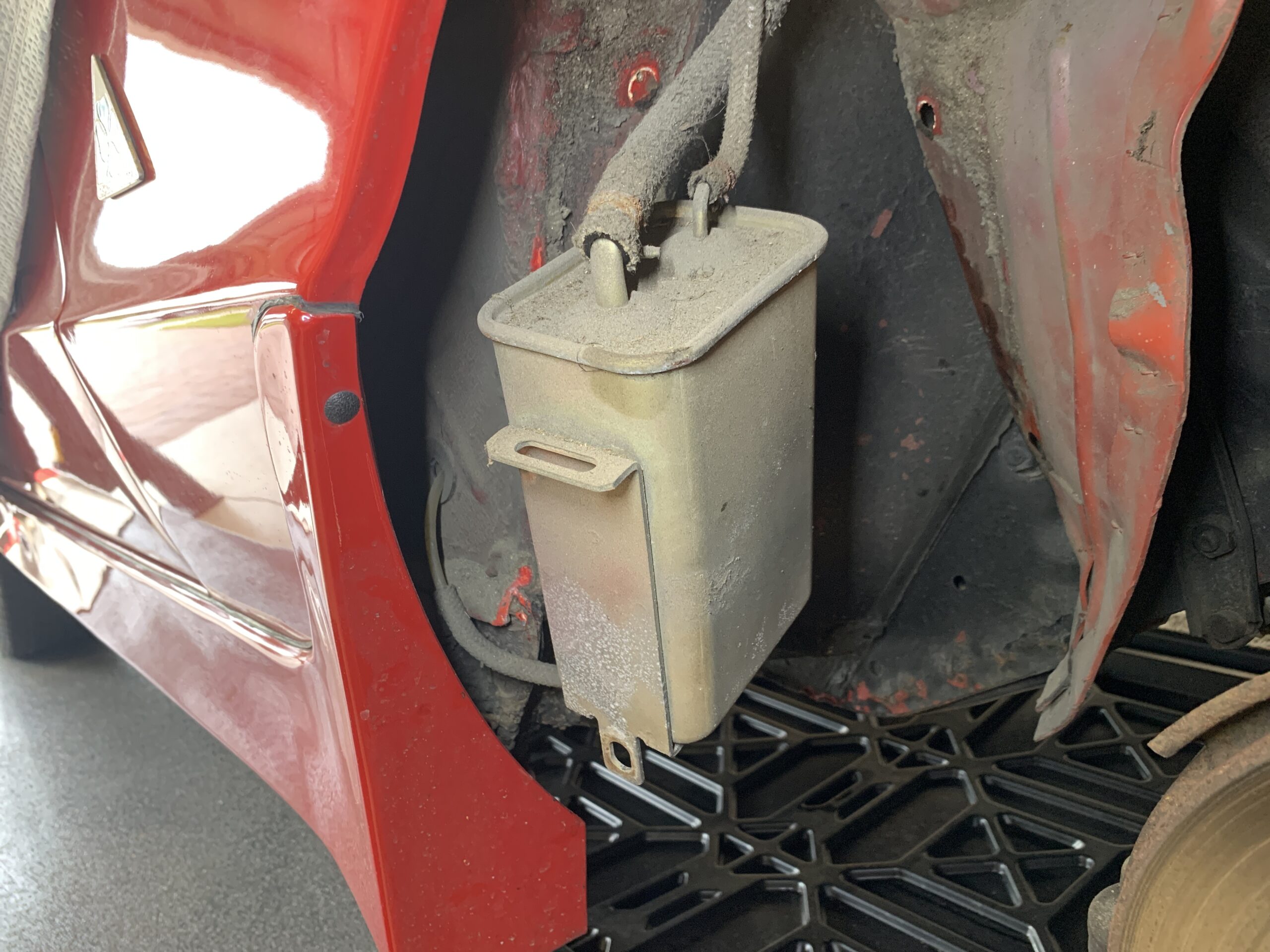
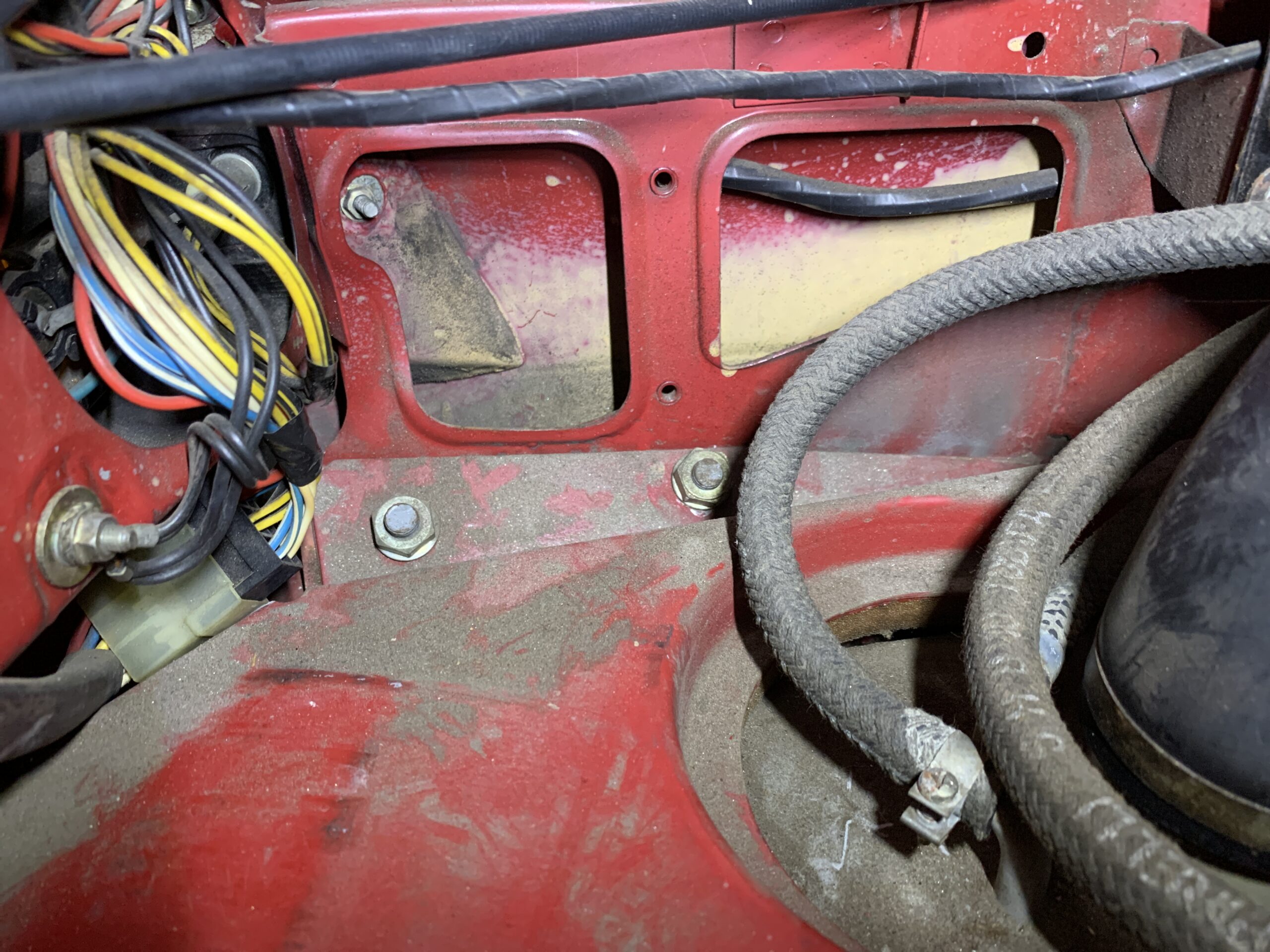
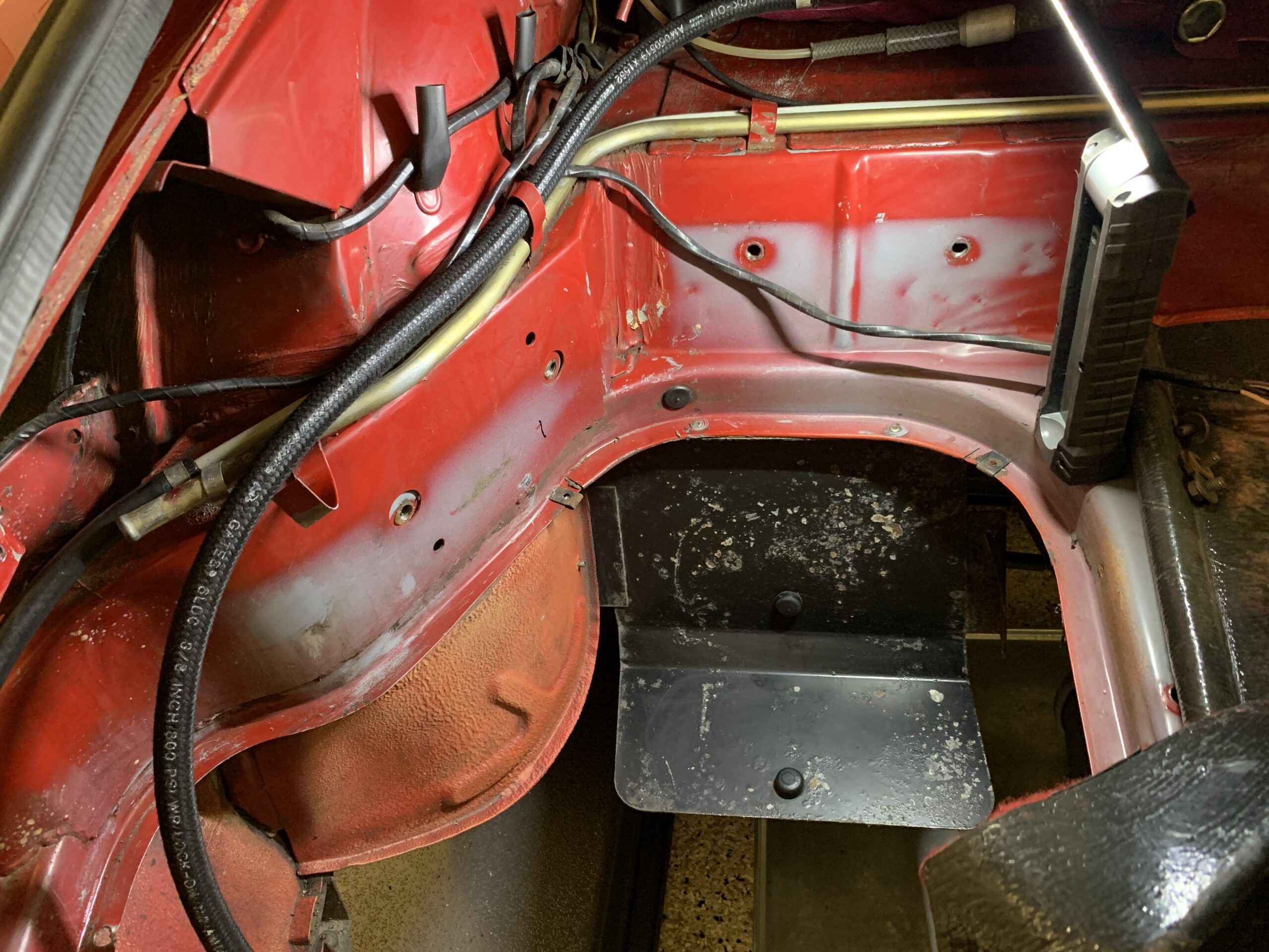
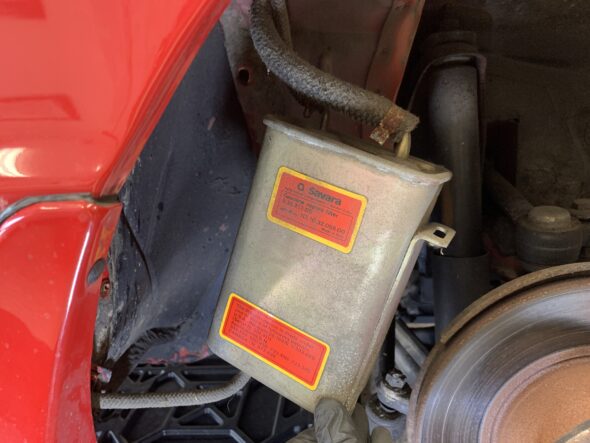
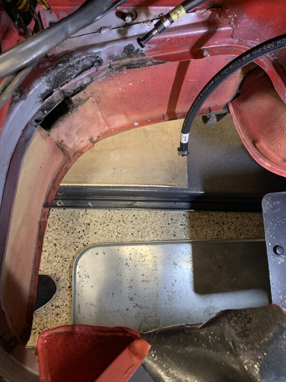
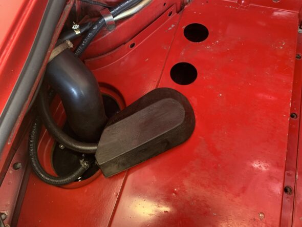
In working to solve the fuel issue detailed previously, I ended up accessing the charcoal canister located behind a panel in the RH wheel well under the fender. To get to the canister, one must first remove the cover panel held in place by three sheet metal Phillips head screws with washers. In my case the uppermost screw was missing. The cover plate can be lifted away although two hoses are running through rubber grommets in the panel.

Panel Covering the Charcoal Canister
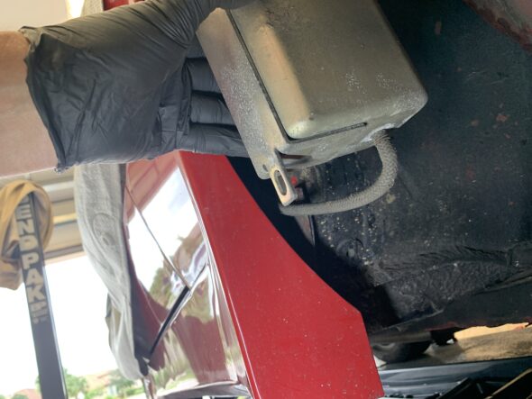
The charcoal canister is then exposed and accessible and can be removed by loosening a 14 mm nut below the canister and lifting the canister upward.
I fully expected the charcoal canister to be rusty and in need of replacement, but it was actually in very good condition. I cleaned it and its cover panel and reinstalled both after letting the canister sit in the sun for several days to make sure the gasoline in the canister fully evaporated.
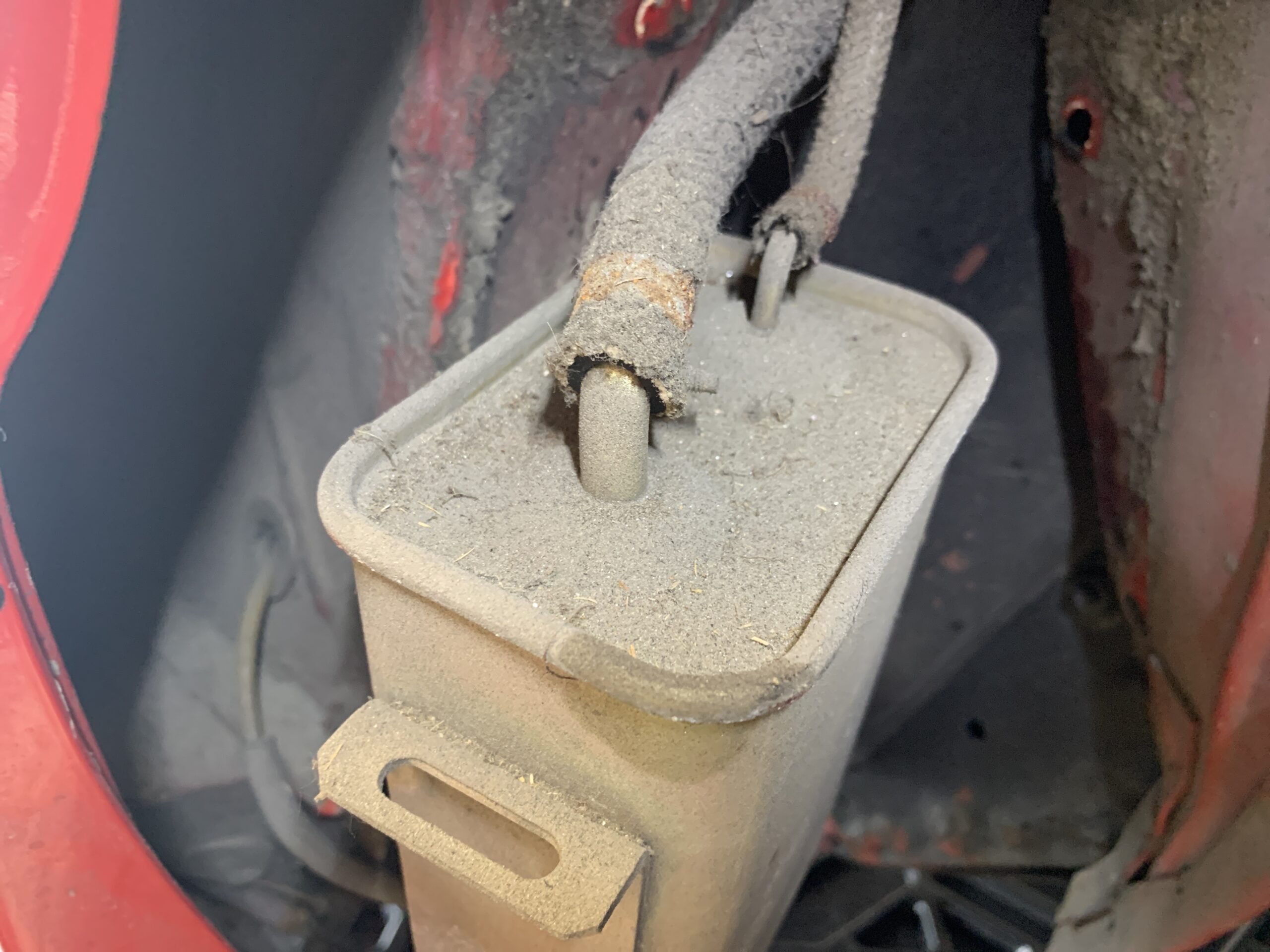
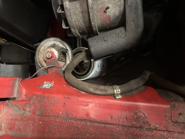
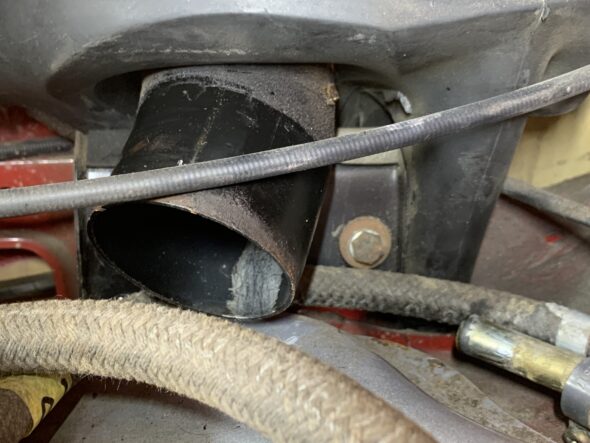
Three hoses are connected to the canister, two on the top and one on the bottom. The larger hose on top of the canister is connected to a port on the air intake pipe. It is 48″ long. The smaller hose on top connects to the lowest of the three vacuum ports on the plenum. It is 43 1/2″ long.
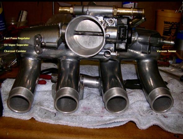
Vacuum Ports at the Plenum
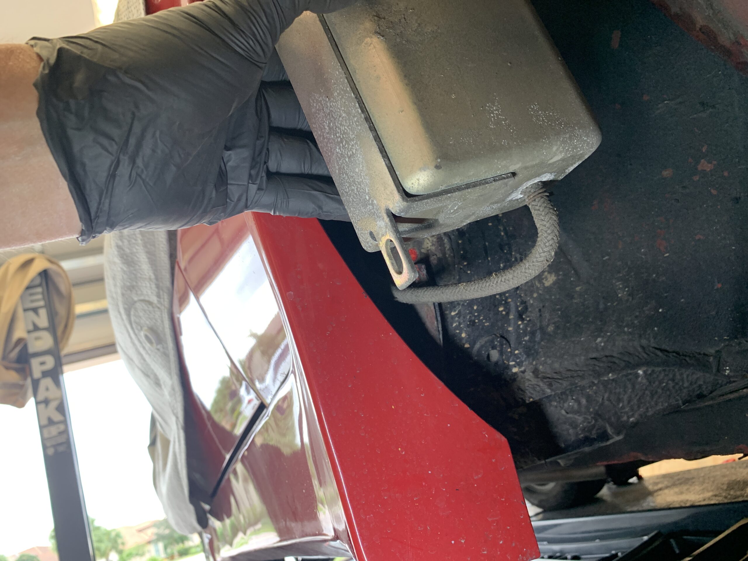
The hose on the bottom of the canister travels through the interior of the car from the expansion tank in the trunk. The two upper hoses were replaced with new silicone hoses.

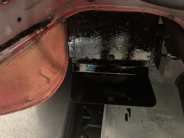
Emissions Charcoal Canister Mounting Bracket and Upper Hoses

Emissions Charcoal Canister Upper Hoses
Emissions Charcoal Canister Lower Hose
Emissions Charcoal Canister in Great Condition
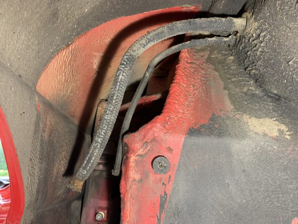
Hoses from Engine Bay to the Charcoal Canister
December 20, 2021
70,900 miles on the odometer
ALFA ENGINE OIL, FILTER AND AIR FILTER CHANGE
Because of my previous episode with fuel being sucked to the engine through the emissions system, I was concerned about gasoline in the engine oil so I decided to change the oil and replace the filter.
I removed oil filler cap on the cam cover, and removed the oil sump plug to let the engine oil drain. The sump plug is 1 1/16″ or 27 mm. The oil did smell a little like gasoline. I Inspected oil filler plug for metal filings, and was pleased to discover none. I waited about 30 minutes and reinstalled the sump plug with a new copper crush washer.
To remove the oil filter one must first remove the air cleaner assembly to access the filter. While it is true that the filter can be tightened or loosened from below the car, it will not fit between the oil sump and the chassis, so it must be removed from above. I also loosen the nut securing the LH horn and moved it out of the exit path of the filter. I put a pan directly below the oil sump and unscrewed the oil filter and removed it from the car. A 93 mm oil filter wrench will fit the Alfa oil filter.

oil sump and oil filter
Oil filter removal
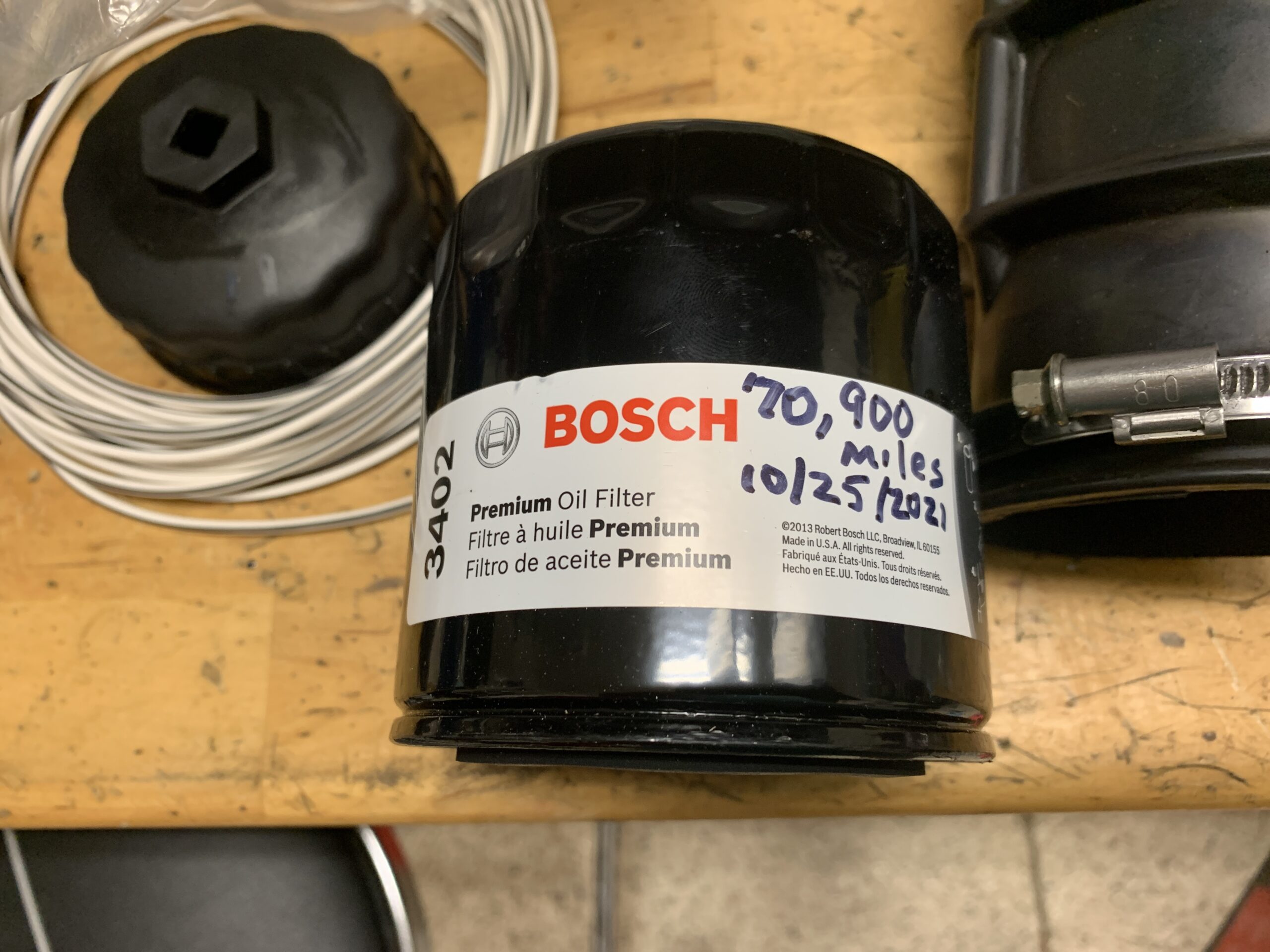
I then Installed a Bosch premium oil filter 3402 at 70,900 miles on 10 25, 2021. I hand tightened the filter and reattached the horn. I then replaced the engine oil with 6 quarts of Valvoline Racing Oil 20W-50. After running the engine and then letting it sit overnight I will add the additional oil needed to get the level to the proper mark on the dip stick.
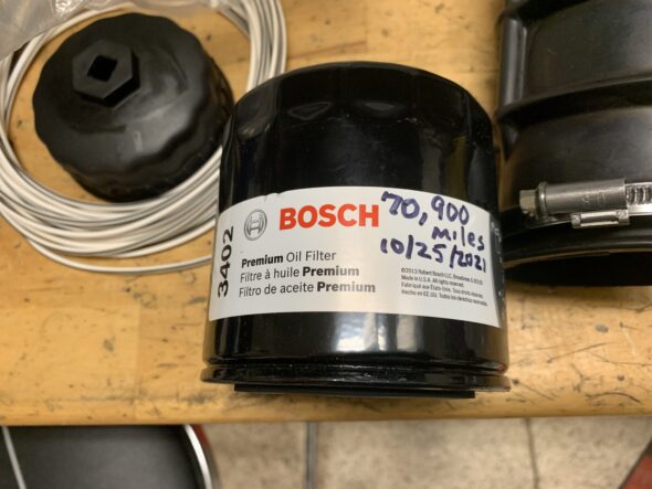
Bosch Oil Filter
Since the Air Filter Casing was open I took advantage of the opportunity and installed a new air filter from Beck/Arnley.
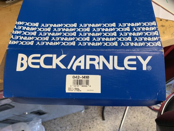
New Beck/Arnley Air Filter
December 15, 2021
70,880 miles on the odometer
FUEL TANK, FUEL HOSE, FUEL FILTER, FUEL PRESSURE REGULATOR REPLACEMENT
What should have been a fairly straightforward task turned into a real fiasco that ultimately took two months to resolve. While I am documenting this in December the process began in mid-October! I am not going to chronicle the starts and stops of the process. Instead I will provide a brief summary of events in several opening paragraphs and then detail the replacement process as it would normally proceed – without incident!
I installed the new tank sourced from Classic Alfa in the UK. I also replaced the fuel hoses in the trunk and inspected and reinstalled the pump/sender with a new gasket and sock filter. Everything went fine. Once completed, I went for a 7-8 mile drive. I returned home to check on all of my hose fittings for any leaks before going back out to get more fuel in the tank. I did have a few screws on the pump/sender that had a very slight leak. I tightened those down a bit more and then went for a 2 mile drive. I stopped and checked the screws for leaks and there were none. I actually thought to myself that the car was running better than at any time since I had inherited it from my father, especially at idle. Very smooth.
I then restarted the car to go out to fill the tank. I got a few blocks from my house and the car stalled at idle when I came to a stop sign. I started it again, turned around and headed the few blocks back home. The car quit a time or two on the way home but I nursed it back onto the lift in my garage where it quit again. It acted like it wasn’t getting fuel. I thought what the hell. I know these Alfa Spiders are great cars, but this one seems to have just one problem after another.
After a few minutes I noticed that fuel was pouring (not dripping) down from the engine at the location of the engine air filter. I raised the hood and saw that fuel was leaking out around the air flow sensor. I disconnected the rubber duct from the plenum to the air flow sensor and fuel literally poured out over the top of the cylinder Head. I am talking about a cup to a pint or more. It continued to flow for quite a while. Fortunately no fire on a warm engine. Lucky there!
What caused this? Did I somehow cause it with the fuel tank switch out? Hard for me to imagine that anything I did would cause this, but I had to wonder. I am used to carb cars not fuel injection. Clearly the engine was not starving for fuel, it was drowning in fuel.
I solicited the help of the contributors to the Alfa Spider Bulletin Board. I found wonderful assistance there and together we walked through all of the possibilities over the course of the next several weeks.
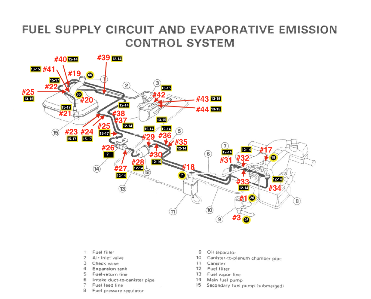
As it all turned out, the fuel tank was defective. In addition to the filler pipe, the tank has two other small pipes. One is the return pipe for fuel coming back from the engine and it is the smaller of the two. The other pipe is a vapor pipe which routes fuel vapors from the fuel tank to the expansion tank on the rear shelf in the trunk. From the expansion tank a hose runs to the front of the car to a charcoal canister. To access the canister one must remove a panel in the right front wheel well. the canister is then connected to a vacuum hose at the plenum and to a port on the air intake at the engine.
Along the way we suspected that the Cold Start Injector might be stuck open. We also wondered about the Fuel Pressure Regulator, A blocked return pipe? Switched hoses at the tank? The problem was that the vapor pipe in the tank is supposed to go into the tank about 1/2.” In the tank I had from Classic Alfa the vapor pipe was probably 4″ long and its end was actually submerged in fuel. When the engine was running the vacuum literally sucked fuel through the vapor hose up to the charcoal canister and then up to the air intake which explained the fuel I was seeing at the top of the cylinder head! When I finally checked the charcoal canister it had almost a cup of raw fuel in it and, of course, there shouldn’t be any liquid in it at all.
I reported the issue to Classic Alfa. They apologized and were very responsive. They sent a new tank right away. I installed the new tank, completed the replacement of the fuel hose through the system, dried out the charcoal canister and reassembled everything. The car now runs as it should. What an adventure! Special thanks to all of my new friends on the Alfa Bulletin Board.
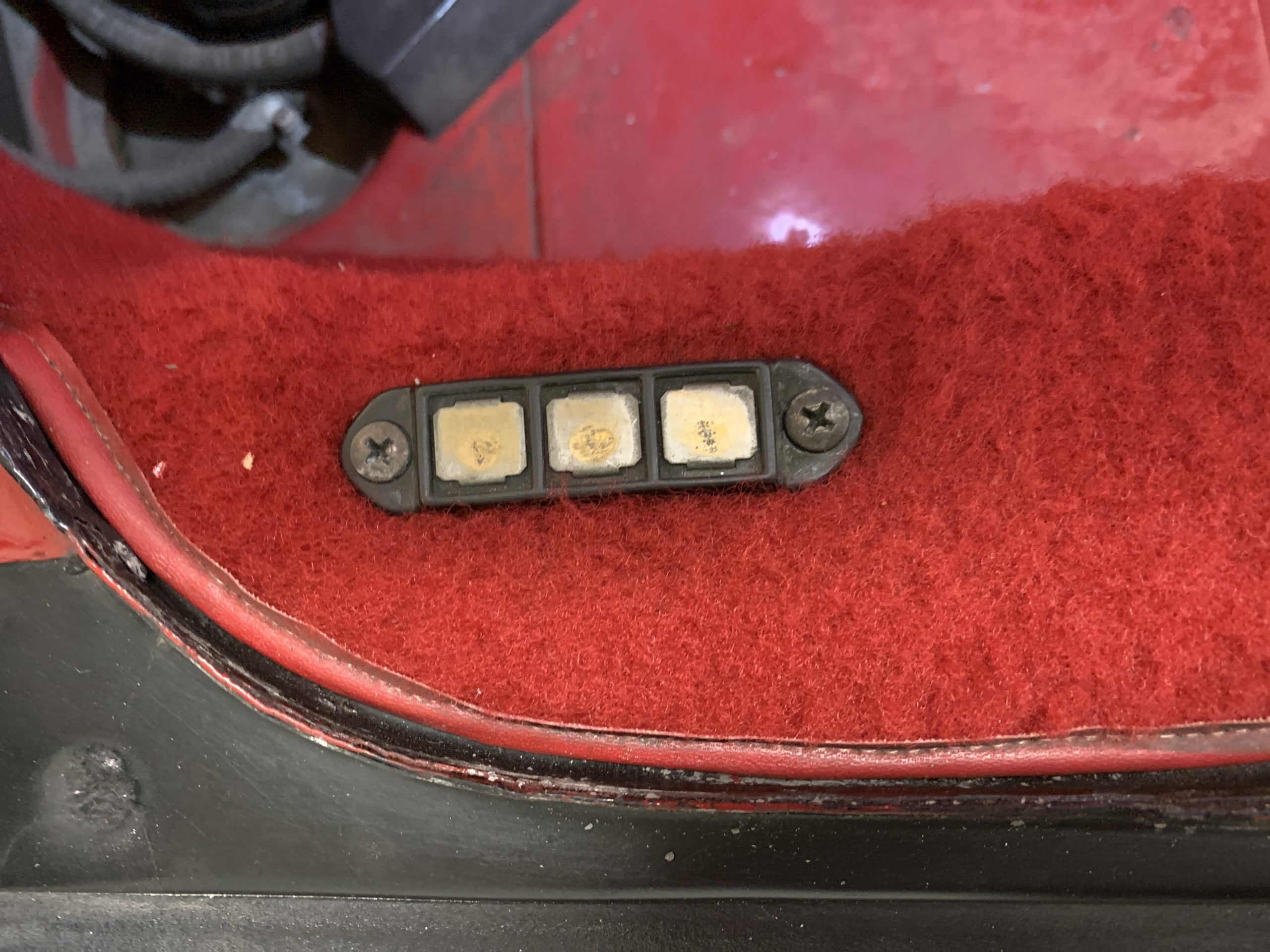
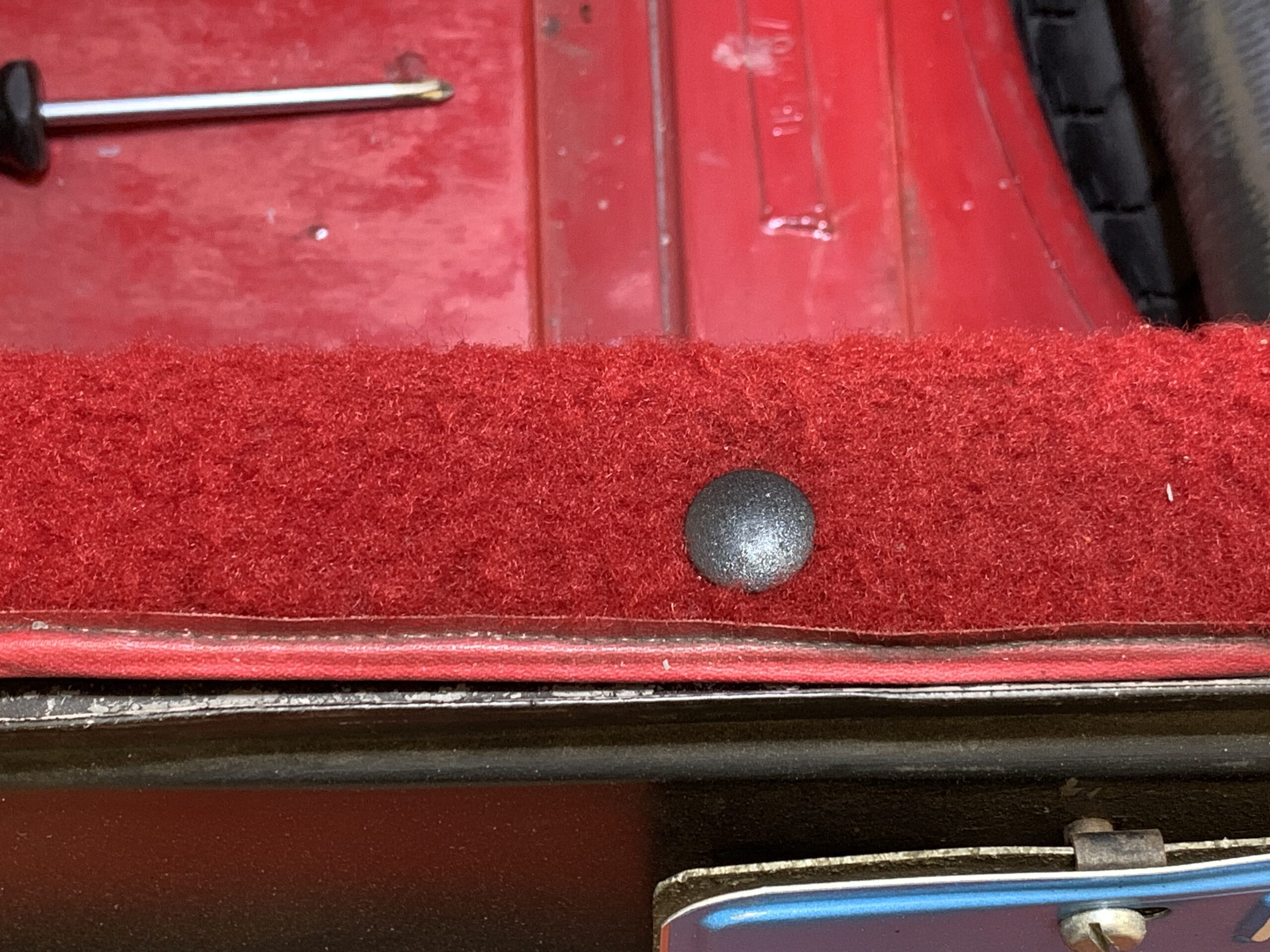
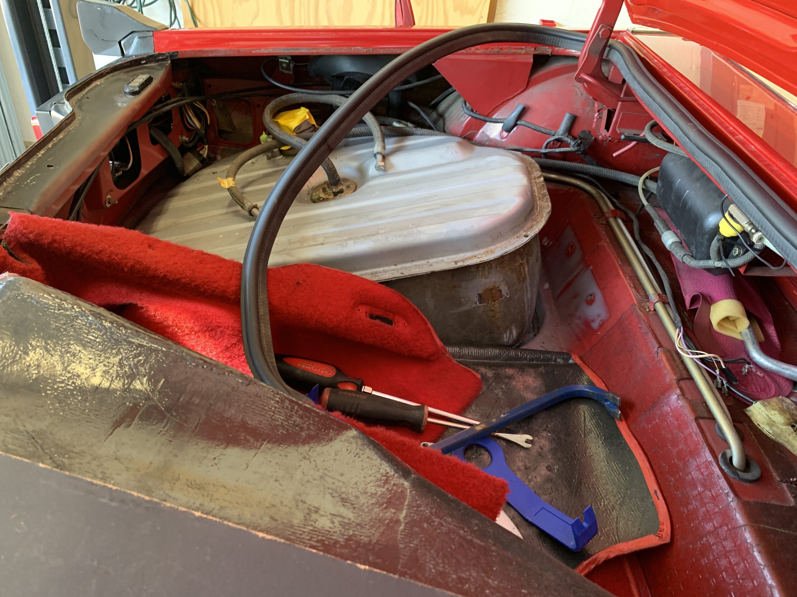
Okay, so back to replacing the fuel tank and the fuel hoses. The first step is to remove the carpet from the left side of the trunk. This entails removing the rubber body seal by simply lifting it up and then also lifting up the vinyl edging on the carper that folds over the body. It is also necessary to remove the electrical contact for the rear license plate lamp by loosening two self tapping screws. There is also one plastic push fastener that must be popped out. The carpet can then be pushed back and out of the way.

license plate lamp contact
Red wire to the left, yellow wire in the center, and ground black wire to the right.
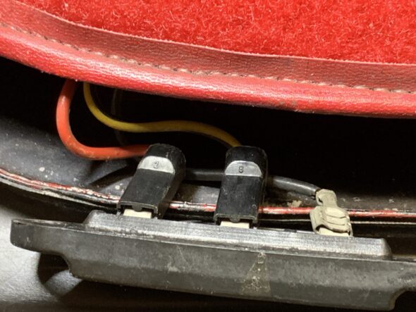
license plate lamp contact wiring

Plastic Trunk Carpet Snap Fastener
Once this is done, there are nine hex bolts/washers and two nuts/washers on captive studs that are 10mm in diameter x 1.25mm x 20mm in length requiring a 17 mm wrench/socket that must be removed to free the trunk floor panel covering the fuel tank. Surprisingly, the foam rubber on the back side of the floor panel was in very good condition. The rubber cover over the fuel sender/pump may be lifted out too.
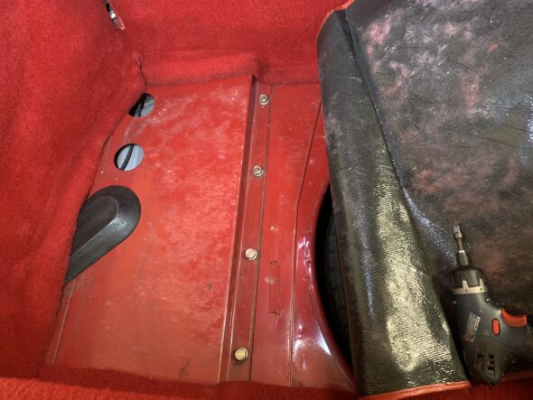
Trunk Floor Panel Fasteners

Trunk Floor Panel Nuts
Before one can remove the trunk floor panel the hoses need to be disconnected. All the wiring to the sender/pump runs under the cover from the back of the trunk, but the large 12 mm fuel delivery hose goes from the fuel pump through the hole in the cover.
Fuel Pump Delivery Hose to Hard Pipe
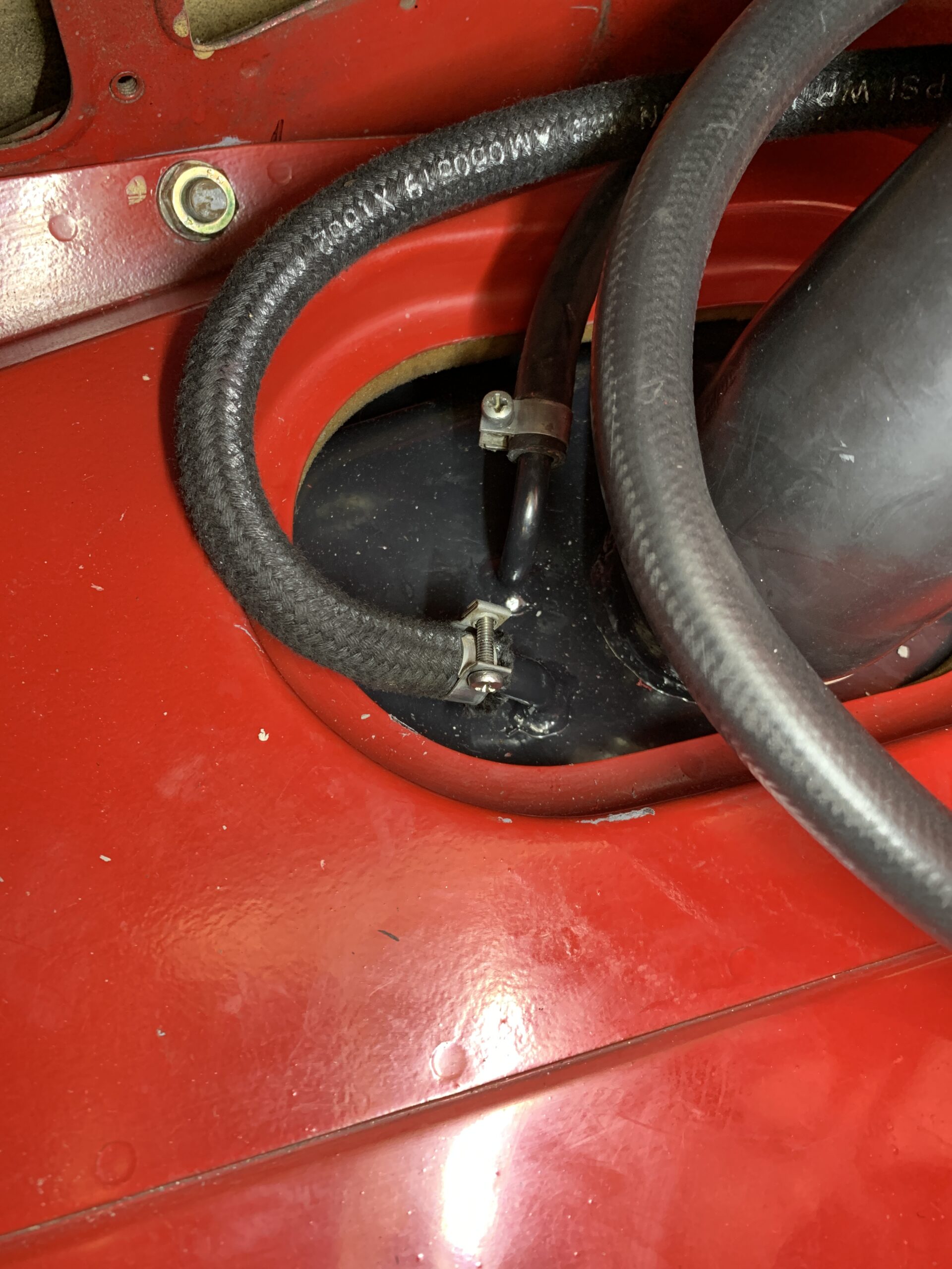
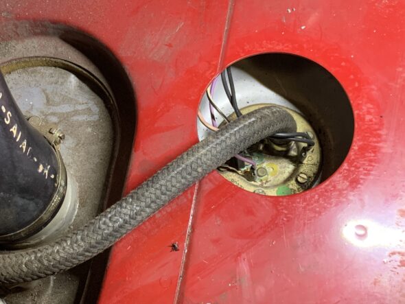
In addition to the large filler pipe that goes from the gas tank door to the tank they are also two smaller 8 mm hoses that connect one to the evaporation system and the other is the return line. These all need to be disconnected in order to remove the cover. This photo shows the hose routing behind the main filler pipe.
Vapor Evaporation and Fuel Return Hose
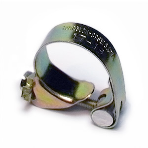
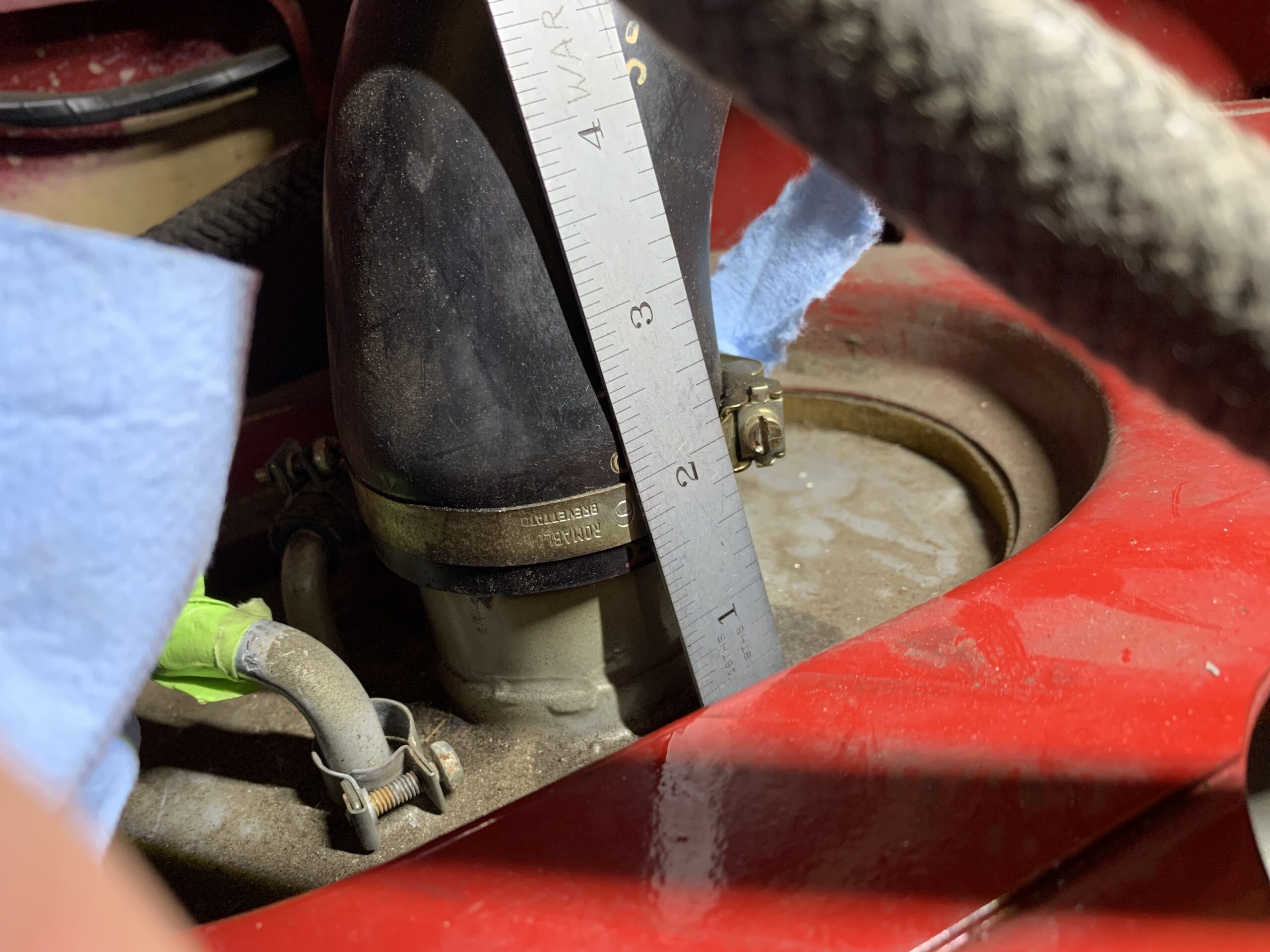
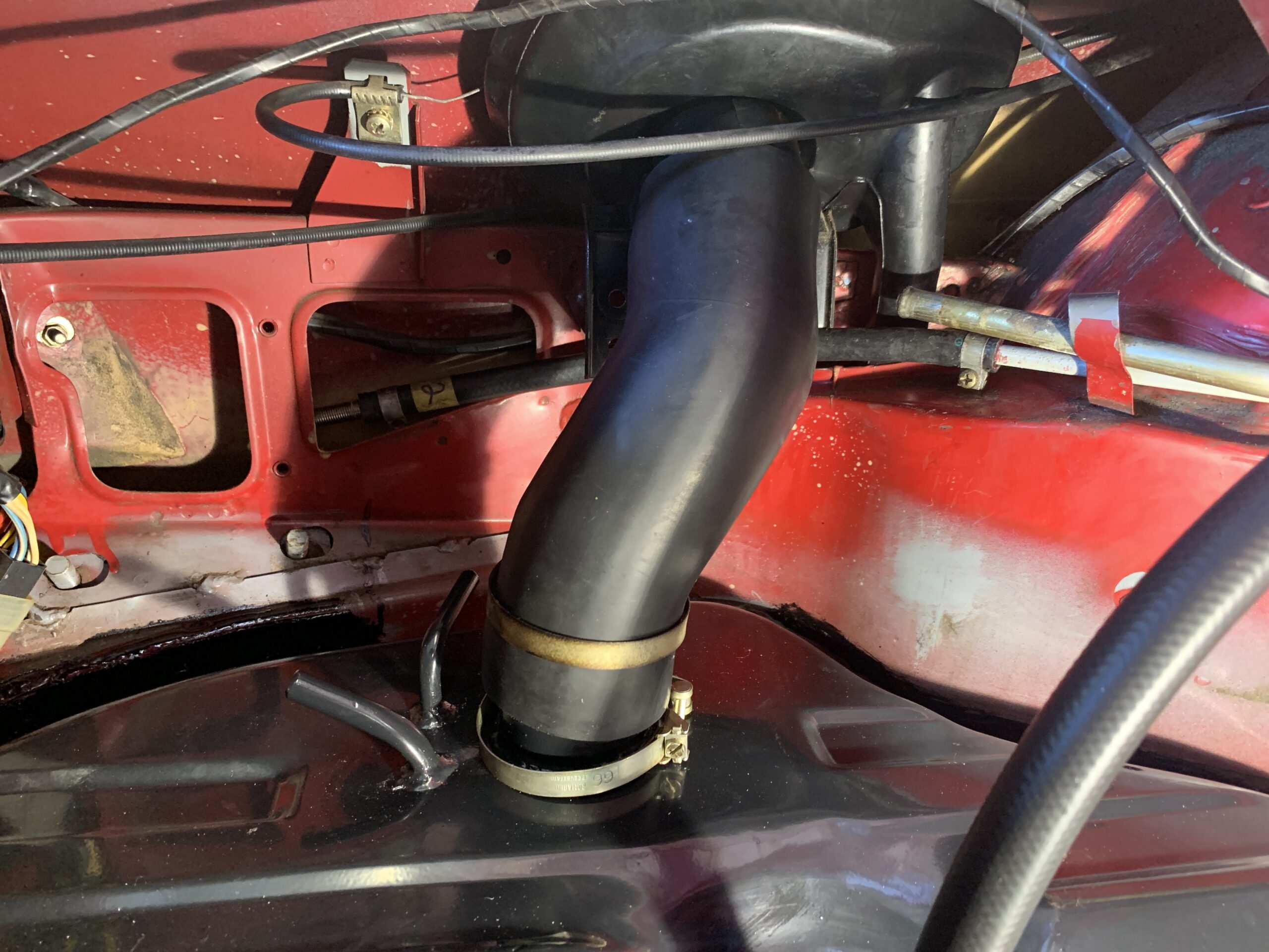
I will be installing a new fuel filler hose and I am not sure if the new hose is exactly the same length as the old one so a measurement was in order. The fuel filler pipe is about 1 1/2” off the tank. Both the upper and lower hose clamps are 66mm.

Fuel Filler Hose
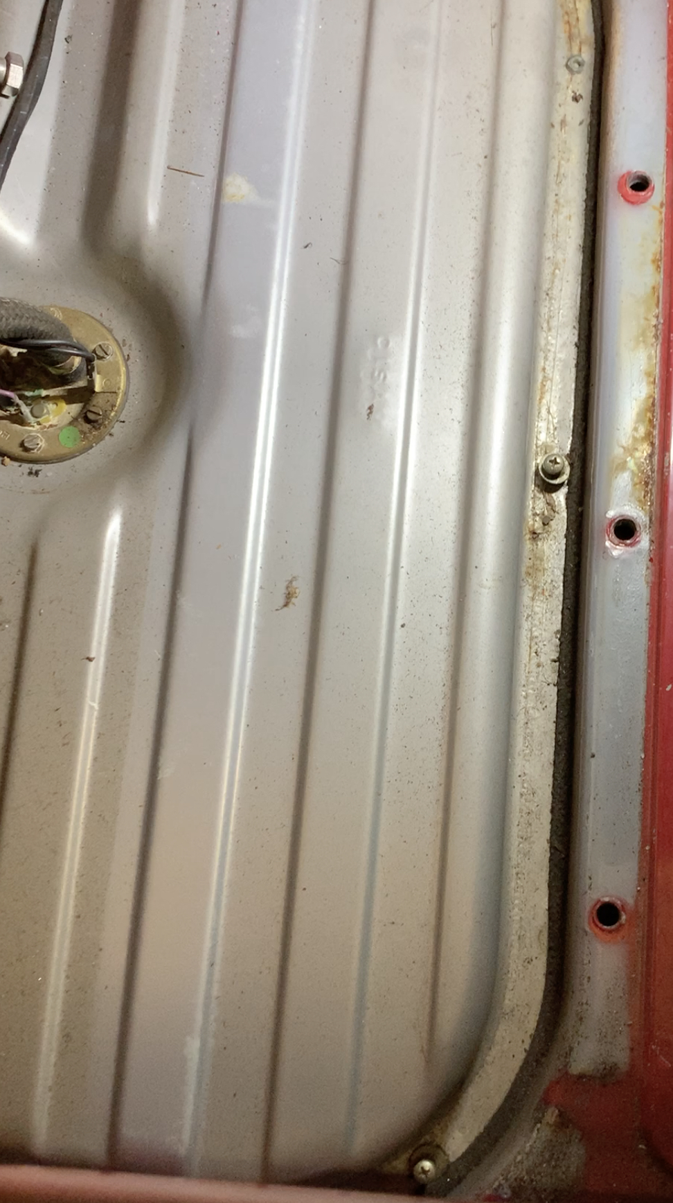
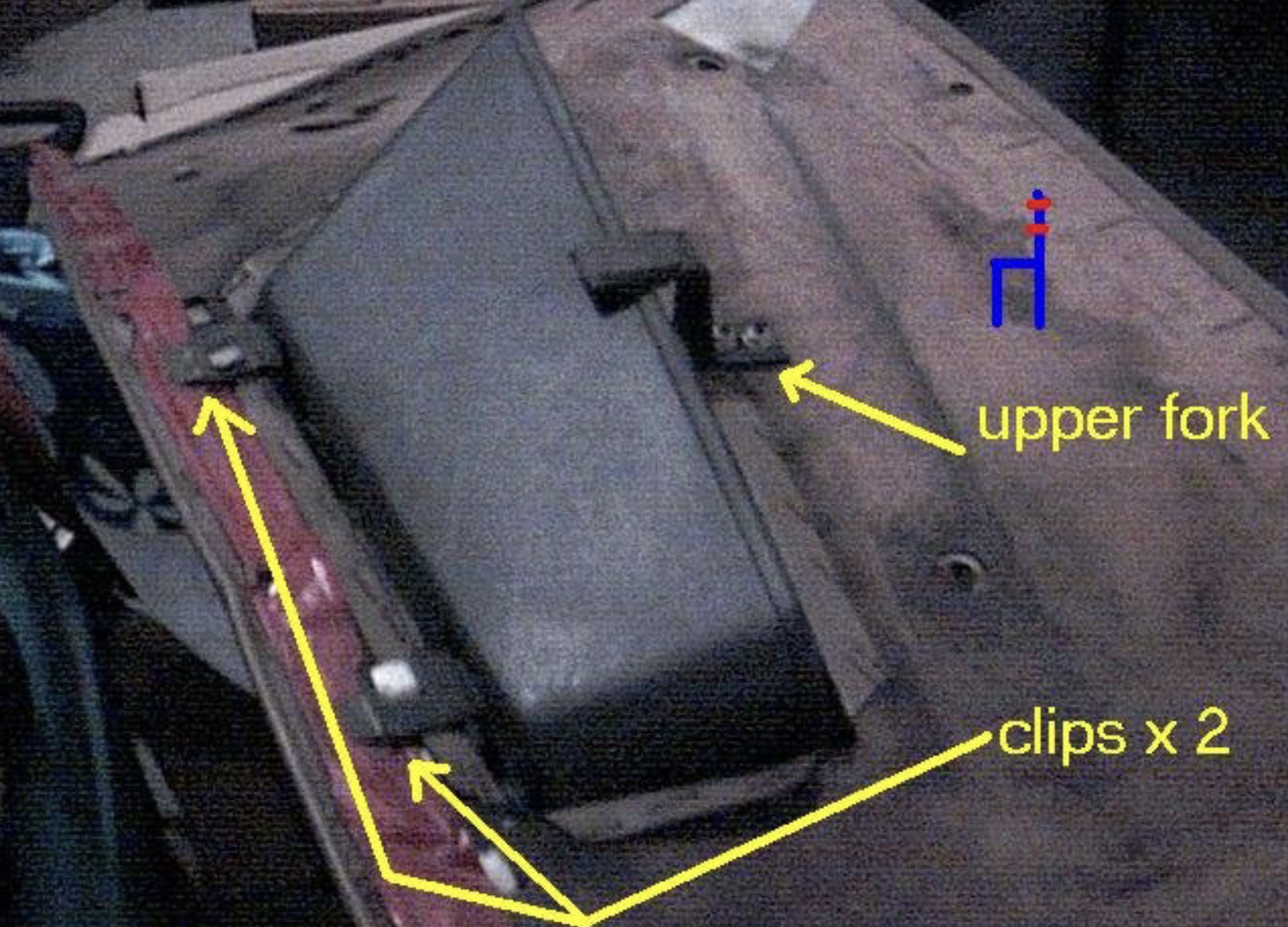
After disconnecting all of the hoses one can then lift out the trunk floor panel. It is best to left from the rear and angle upward to the right to retrieve the panel. Once the panel is removed the tank is exposed, and it is secured to the floor with five Phillips head screws and washers going into clip-on nuts on the body flange. I discovered the fifth screw on the far left of the tank the hard way after trying to lift the tank out for a while without it budging.
Five Fuel Tank Mounting Screws
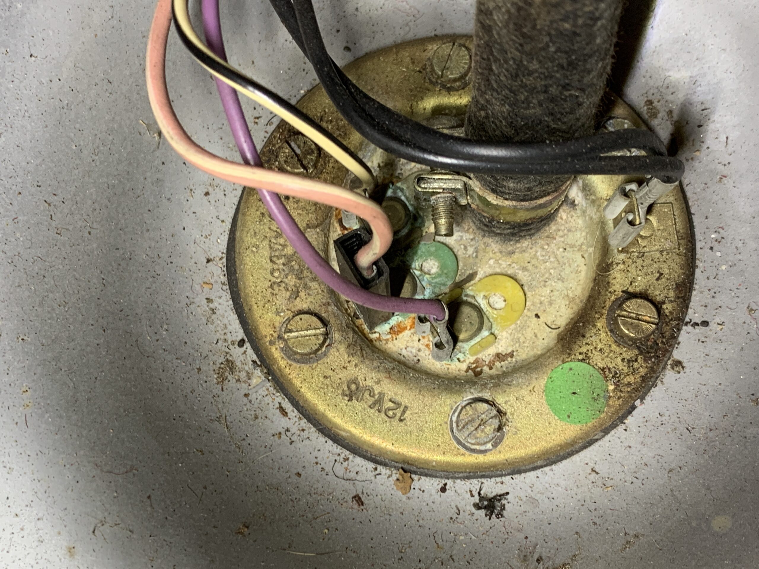
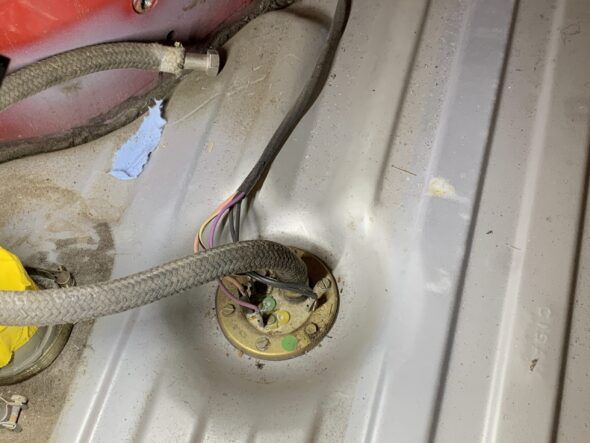
I’m going to leave the pump and sender in the old tank until I have the new tank ready. So I will need to disconnect the wires. This is a photo of how the wiring is attached.

Fuel Sender:Pump Wiring
The black wire goes to the terminal on the right side. The purple wire goes to the yellow terminal. The pink and white wire goes to the green terminal in the middle and the black and white wire goes to the colorless terminal closest to the rear bulkhead.
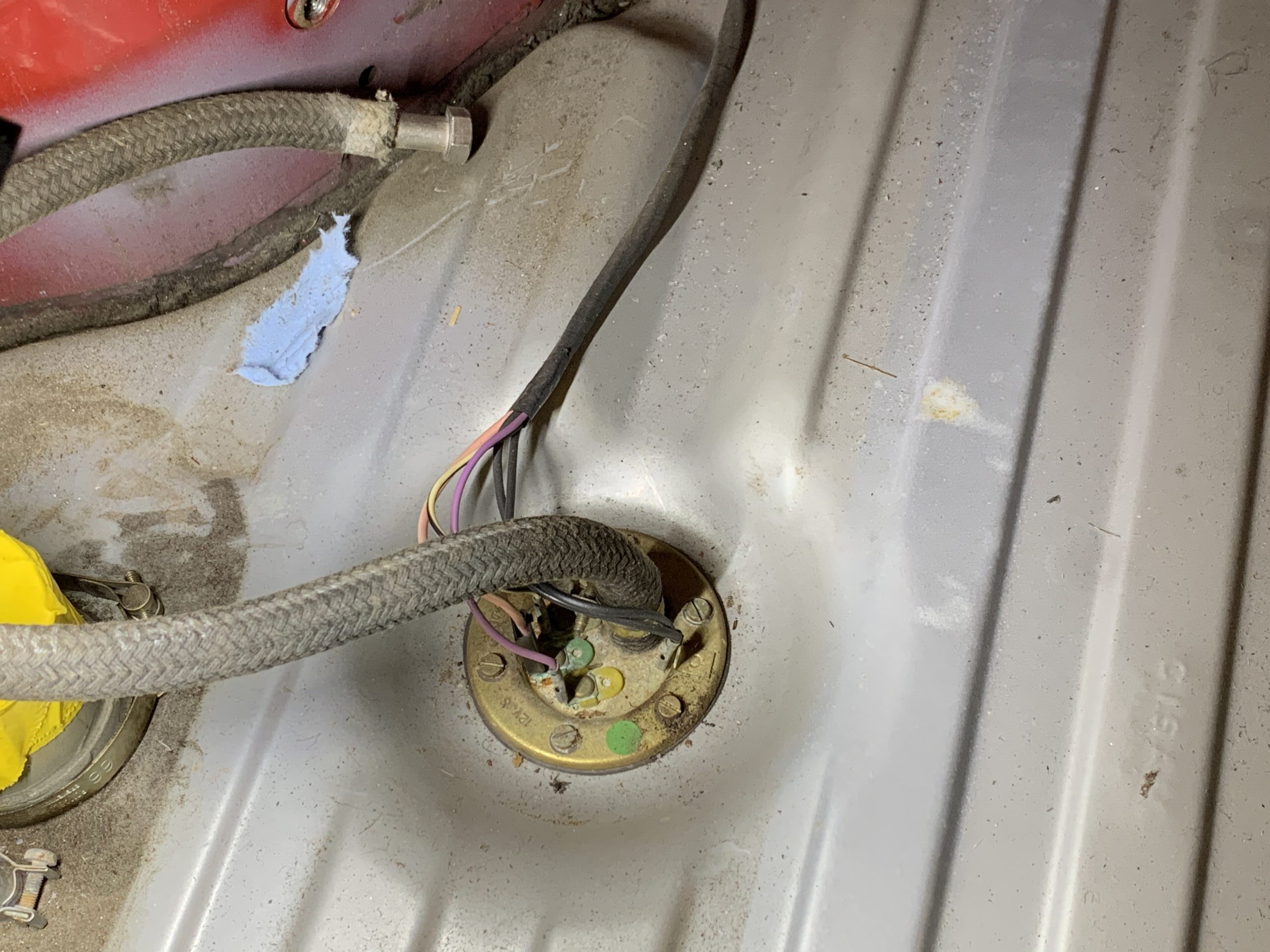
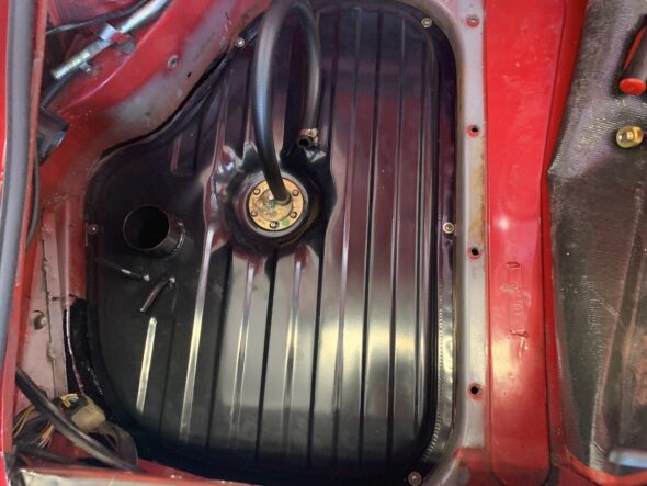
When I put the new tank in I will have the fuel pump and sender and the fuel delivery hose already attached to the pump. This photo shows the orientation of the sender/pump. It is important to reinstall the unit in the same position so that the float on the sender measures the fuel level properly.
Orientation of sender:pump on tank
It may not be necessary, but it helps to at least loosen, if not remove, the fuel inlet. It is mounted with three bolts/washers requiring a 10mm wrench/socket.
Fuel Inlet Mounting
You must lift the tank from the rear, dip the tank at the lower left, and then lift it up to pull it out. Once you have the technique down it is easy.

Removing Fuel Tank
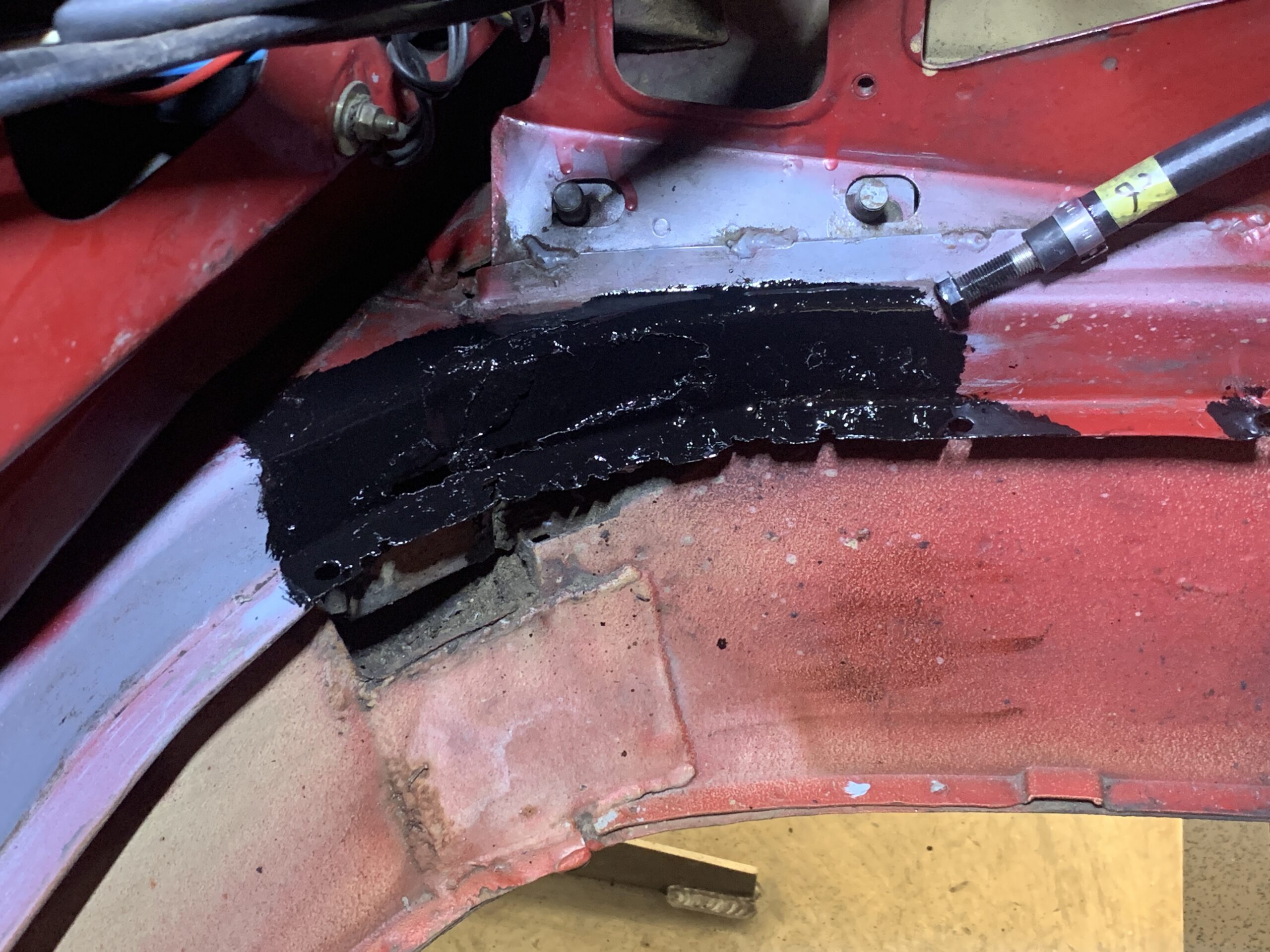
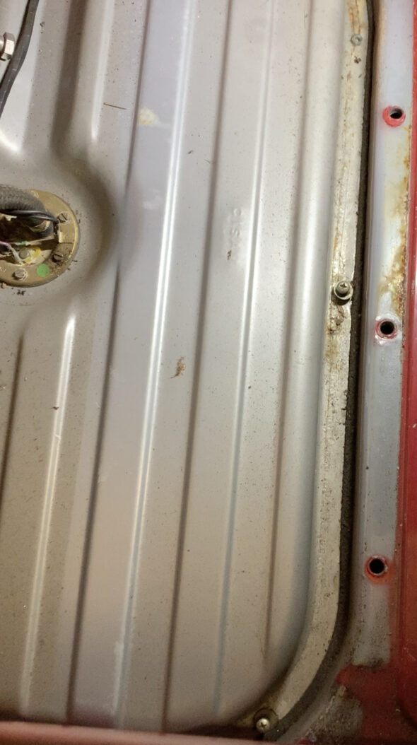
There was a liberal application of a material similar to seam sealer around the body flange between the body and the fuel tank. I cleaned all of this away. I then thoroughly cleaned the trunk area in which the fuel tank sits. Unfortunately, I did have rust in the rear left-hand corner. I did not repair the metal as it was not significant in securing the tank but I did treat the area with rust neutralizer and painted it with POR 15.

Flange Cleaned
Flange Rust

Rusted Flange treated and Painted
There is what I assume to be a heat shield to insulate the fuel tank from the exhaust. While it was accessible I went ahead and painted it with POR 15 as well.
Painted the Exhaust Heat Shield
Installed the 5/16 inch fuel return hose from the hard line in the trunk to the fuel tank. The hose is 11 inches long.

New Fuel Return Hose
Installed the three eights inch hose from the fuel tank to the emissions evaporator canister. This hose is 36 inches long.

Vapor Emissions hose to Expansion Tank
The 12mm fuel hose from the in tank fuel pump/sender to the hard fuel pipe is 22” long. This was fit to the pump before installation in the tank and then the car.
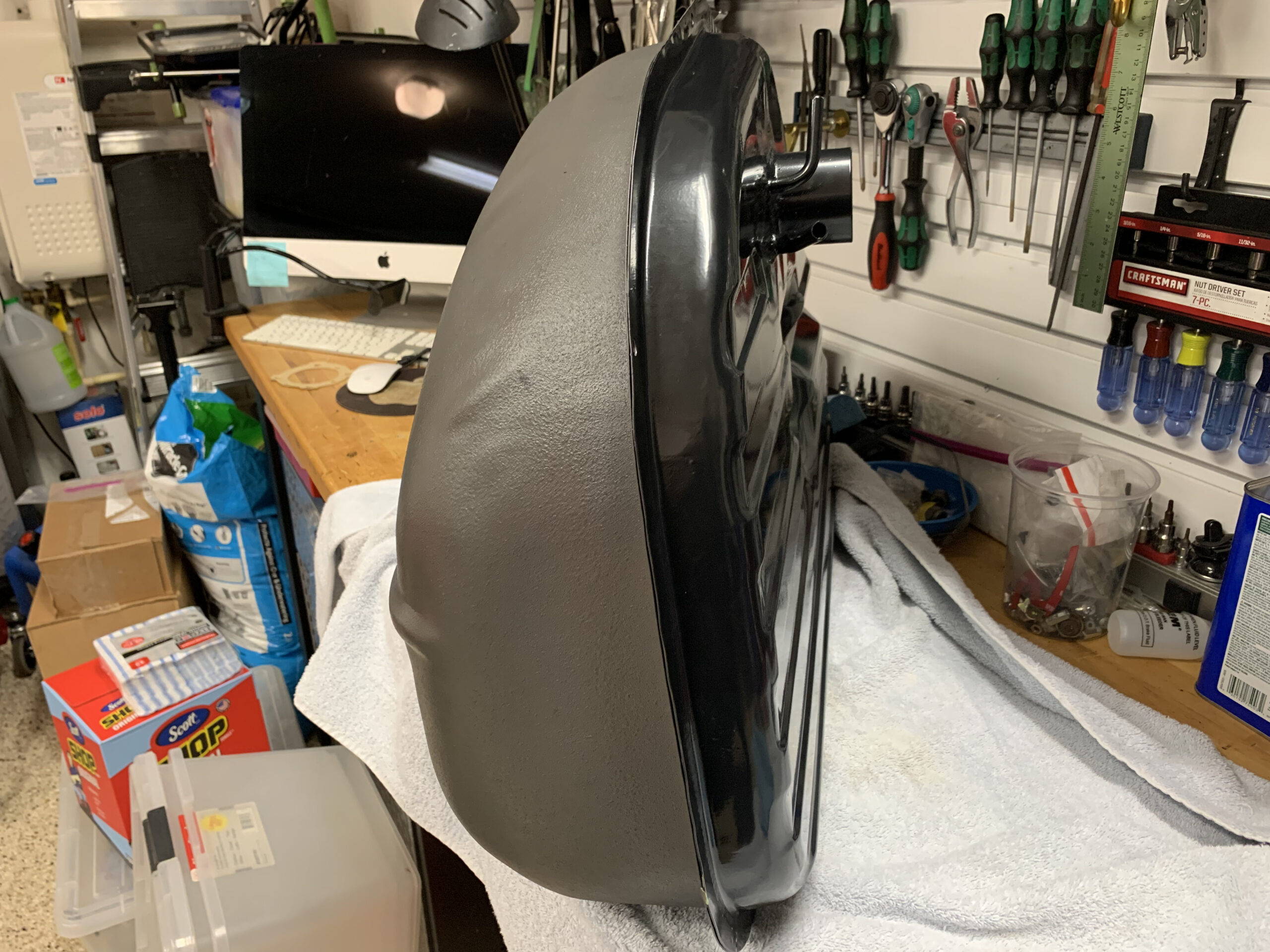
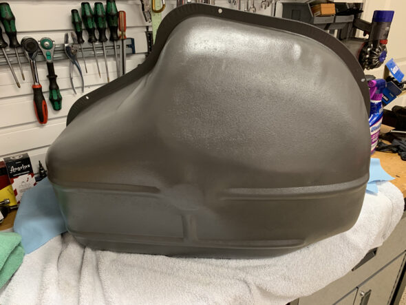
The paint on the fuel tanks as delivered from Classic Alfa is okay, but I wanted to improve the paint job. I painted the bottom of the tank with an undercoating rubberized paint from Eastwood and then overcoated it with a a few coats of ACE fast drying spay paint. The color was “iron.” I left the top of the tank black. I was pleased with how it came out.

New Painted Fuel Tank
New Painted Fuel Tank Bottom
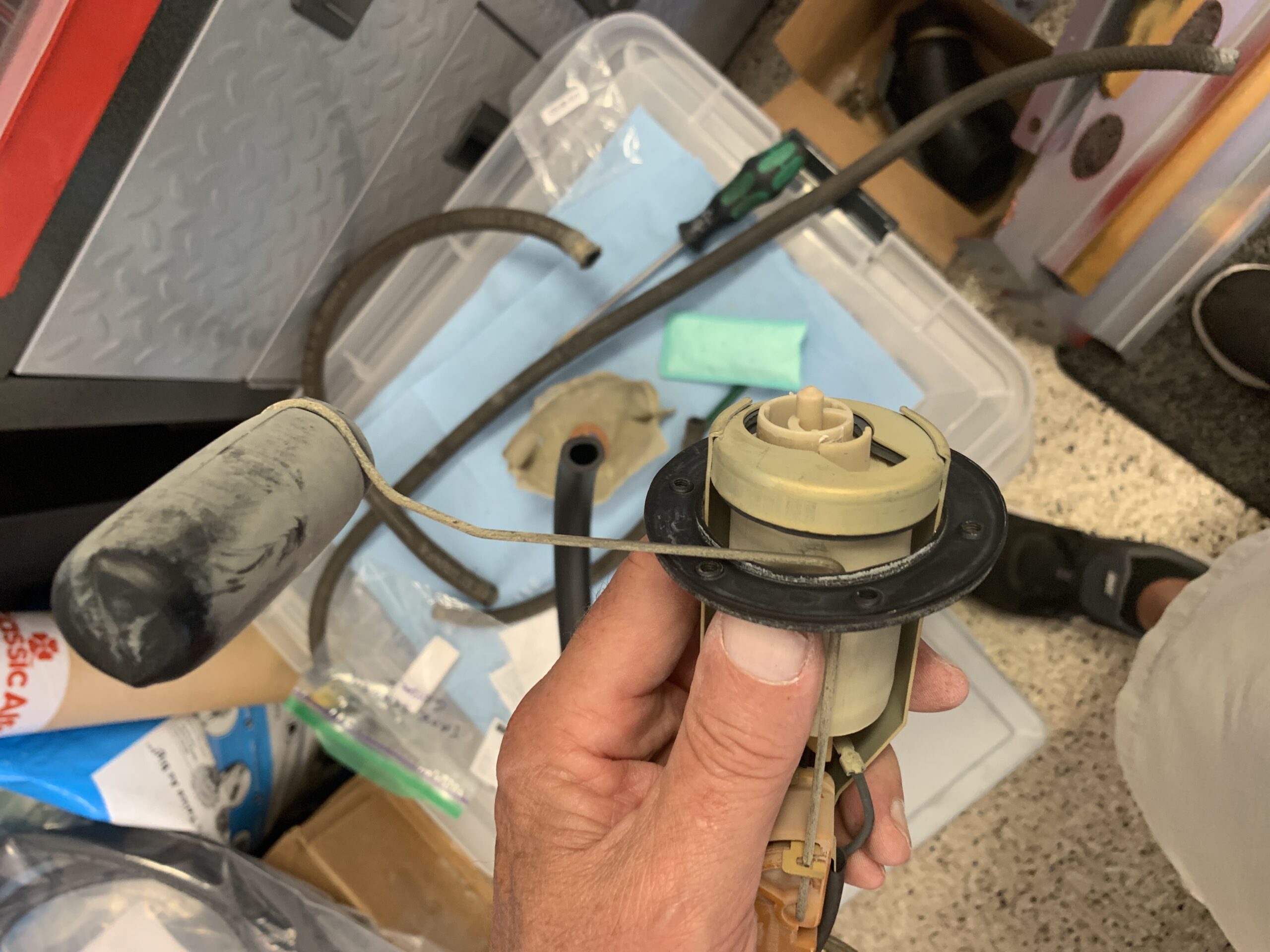
The fuel pumps had been working just fine. The Alfa has two. The pump in the tank is just there to get the fuel to the pump unit under the car where the fuel is pressurized to move up to the fuel injection system. The in-tank unit looked just fine. The stepped rubber hose which can be faulty also appeared to be in good shape so I am just reinstalling everything as it came out of the car with two exceptions.
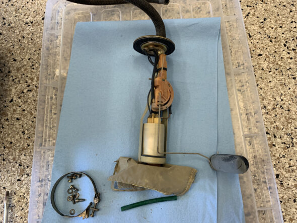
Alfa Fuel Pump, Sender & Filter
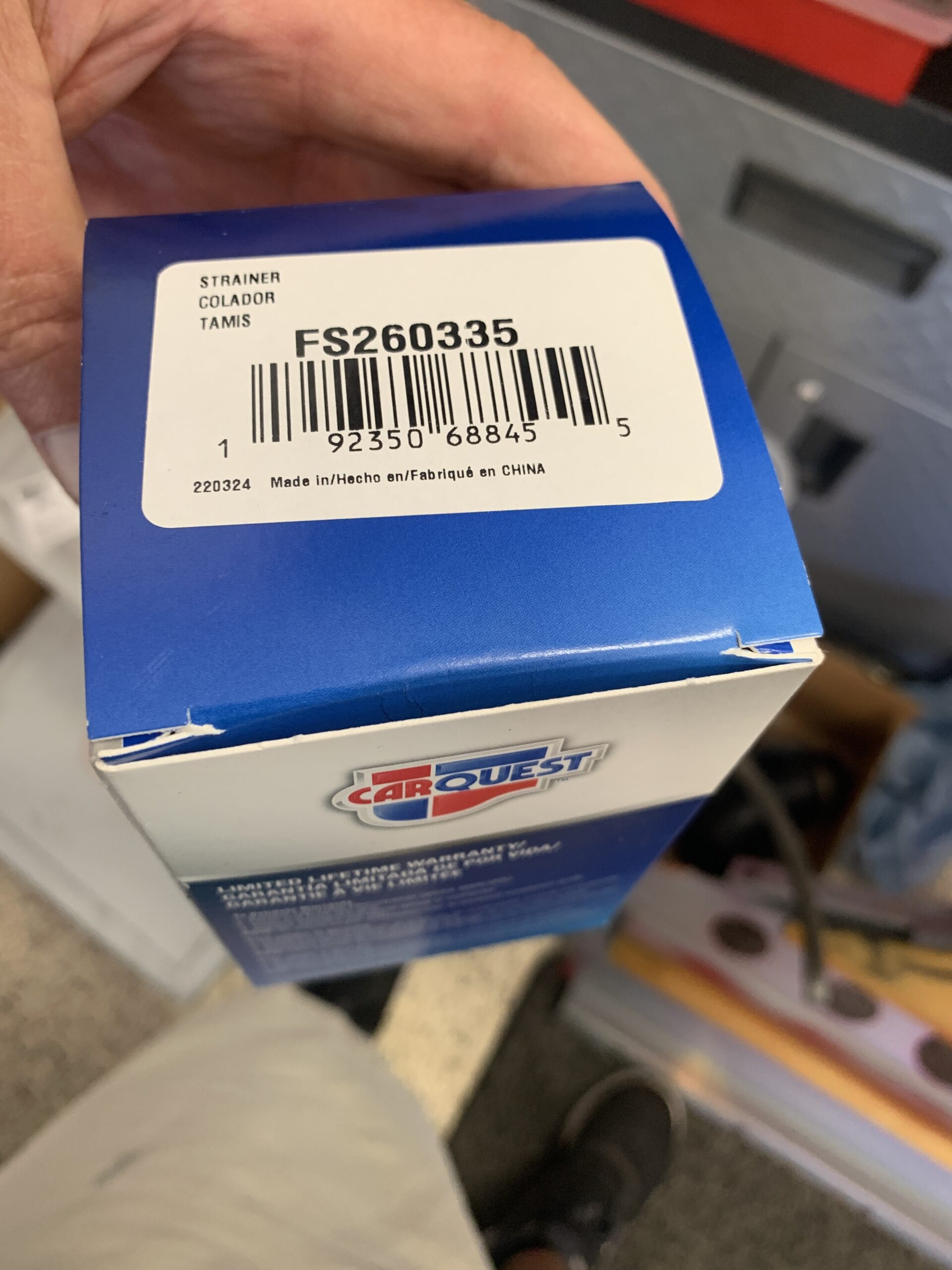
I’m installing a filter for the bottom of the fuel pump that comes from Carquest it is part number STS1BD- 0101 referred to as a strainer. It is very different than the original. But it does fit securely.

In-Tank Fuel Strainer

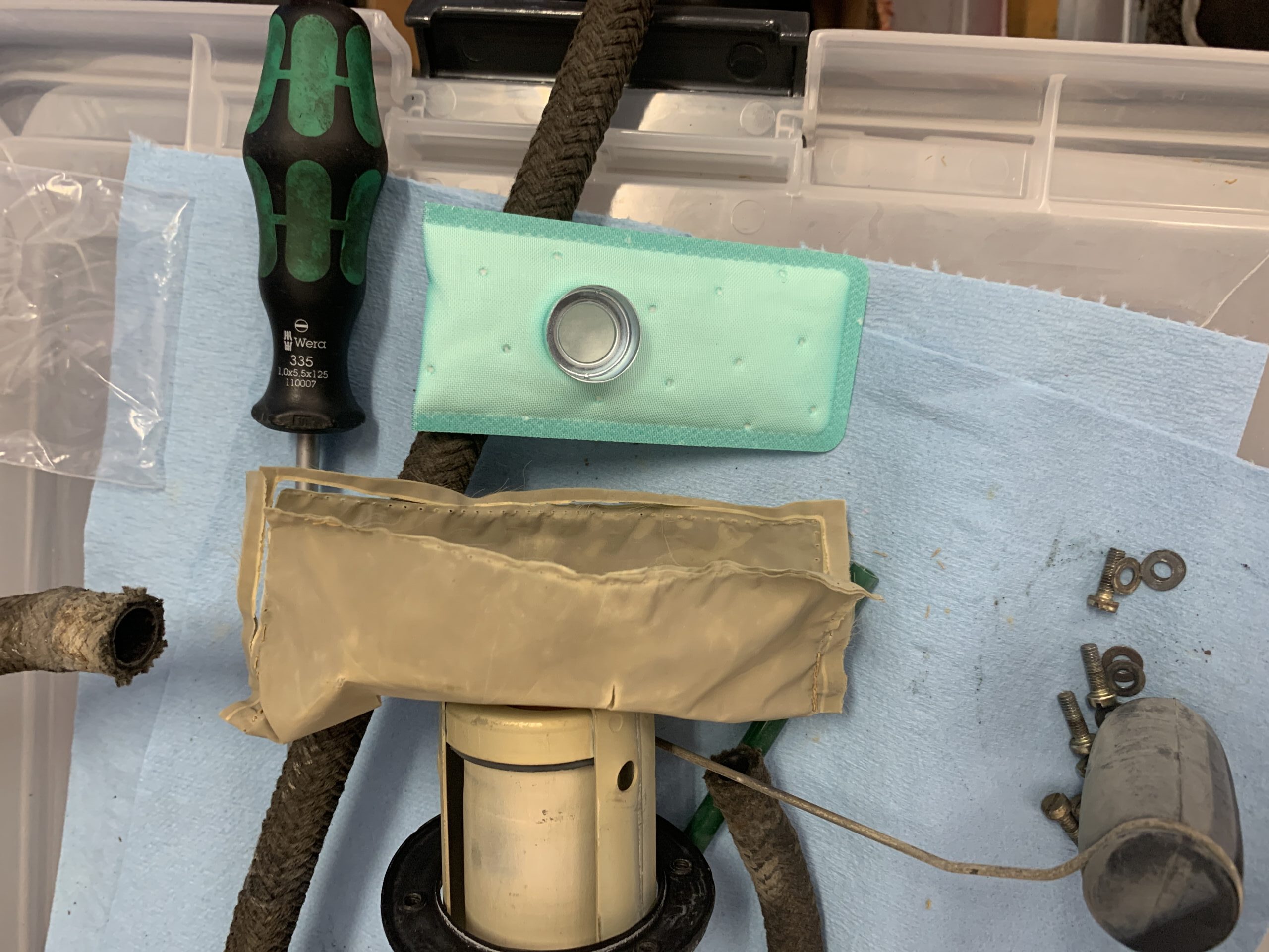
Original Sock Filter and New Strainer
After the old filter was removed I slid down the neoprene seal that seals the sender/pump to the tank. I then installed the new seal sourced from Classic Alfa followed by the strainer.

Replacing the sender/pump seal to the tank
Upon removal of the old seal, It doesn’t appear that any type of sealant was used between the fuel pump top and the seal. However, I used a very thin coat of blue hylomar. I installed the assembly into the new tank and tightened down the mounting screws.
I purchased a rubber seal that fit around the body flange upon which the tank rests. I glued it to the flange with a 3M adhesive.
As stated previously, by raising the end of the tank near the bulkhead and tilting the left side downward I was able to slide the tank into place. I then tightened down the five screws that secure the tank to the chassis.
New Tank Installed in the Car
It was then time to install the tank cover to the floor of the trunk.
Trunk Floor Panel Covering the Fuel Tank
Trunk Floor Panel Installed
I then connected the hoses and installed the rubber cover over the tank floor.
New Hoses and rubber cover Installed
Before replacing the fuel filler pipe I installed a new Filler Neck Seal sourced from Classic Alfa. It is a little tricky getting it to fit perfectly but it can be done.
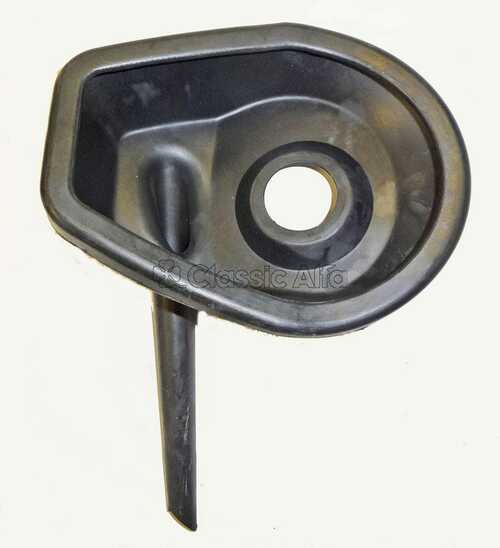
Fuel Filler Neck Seal
This was followed by the installation of a new fuel filler door seal.
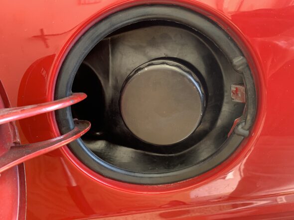
New Fuel Filler Door Seal
The next step was to reinstall the metal fuel filler neck with the three 10mm hex nuts/washers and the new rubber fuel filler hose including tightening the two 66 mm Romablok hose clamps.
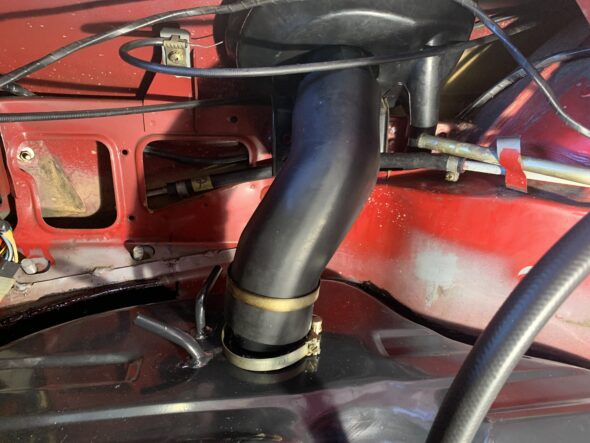
Fuel Filler Neck and Pipe Installed
Reattaching the fuel return hose and the vapor hose was completed and then the two nuts and nine bolts securing the trunk floor cover were replaced and tightened.

Fuel Vapor and Return hoses installed

Fuel Vapor, Return and Delivery hoses installed and clamped
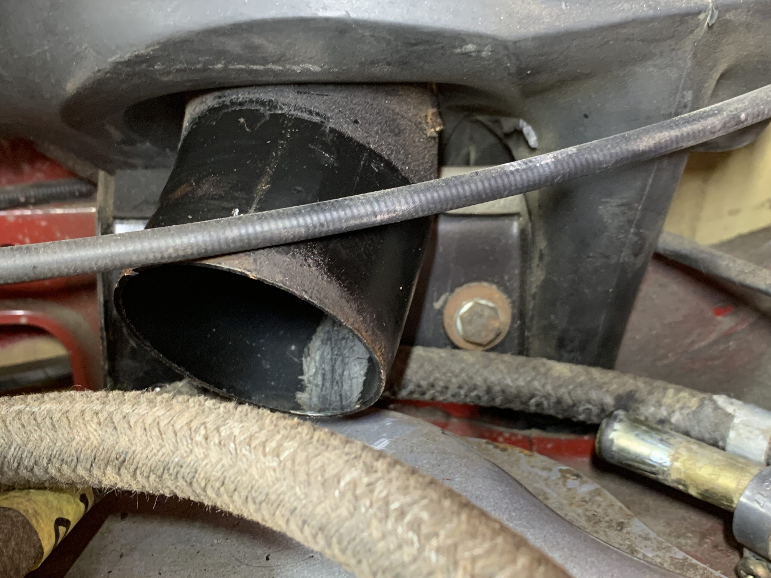
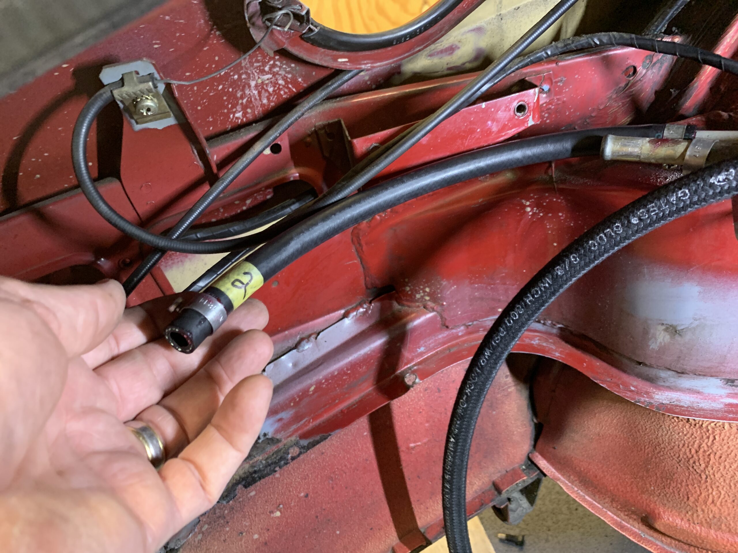
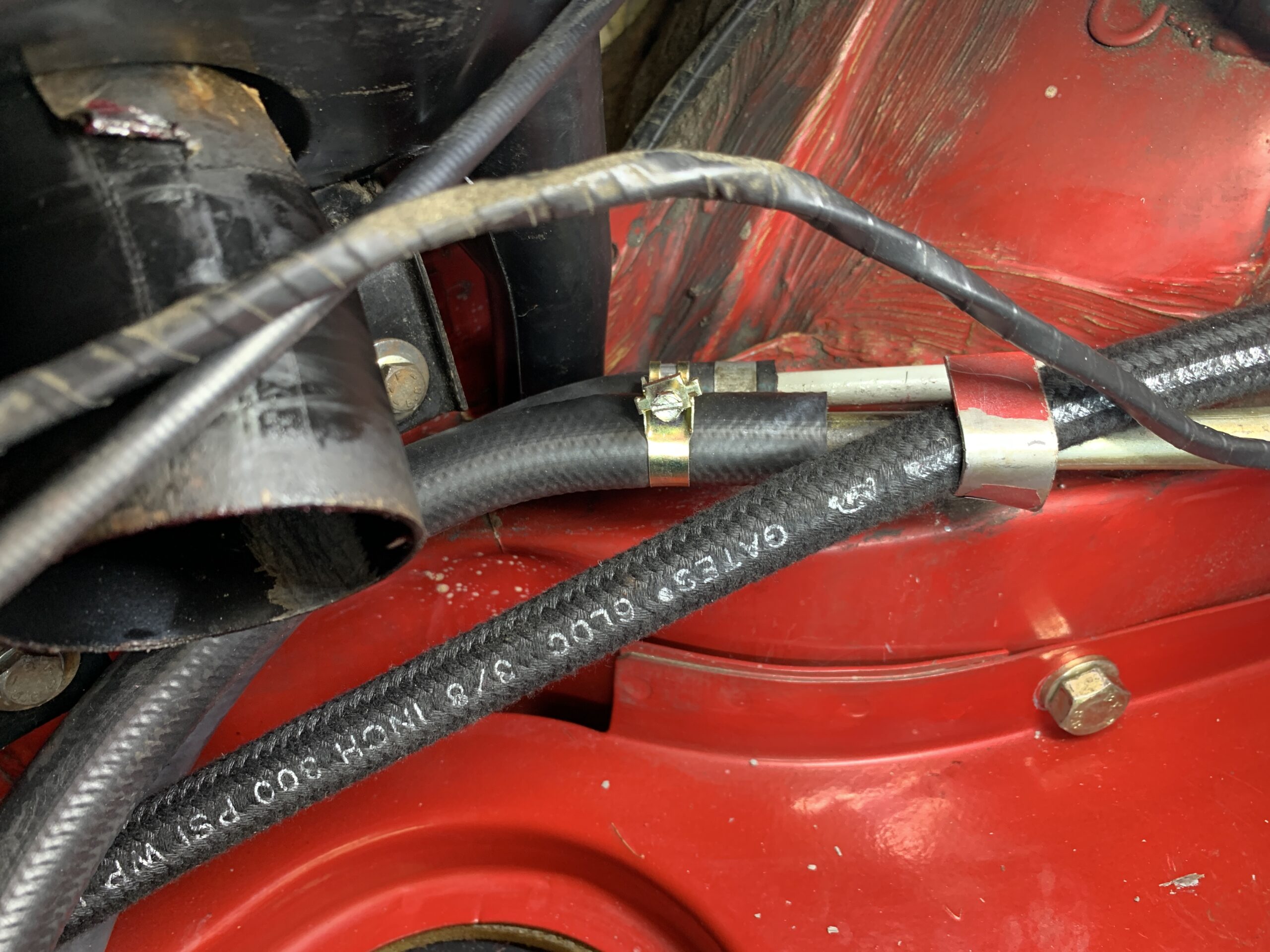
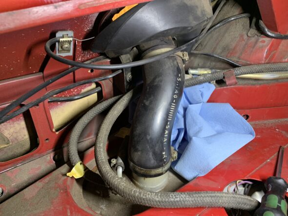
With the tank taken car of, it was now time to replace the rubber fuel hose under the car. Most of it looked original and definitely in need of replacement. At first glance it appeared that quite a bit of hose needed to be replaced, but in facf, most of the system consists of steel pipe that is covered with braided hose.
Steel Hard Pipe covered with braided hose
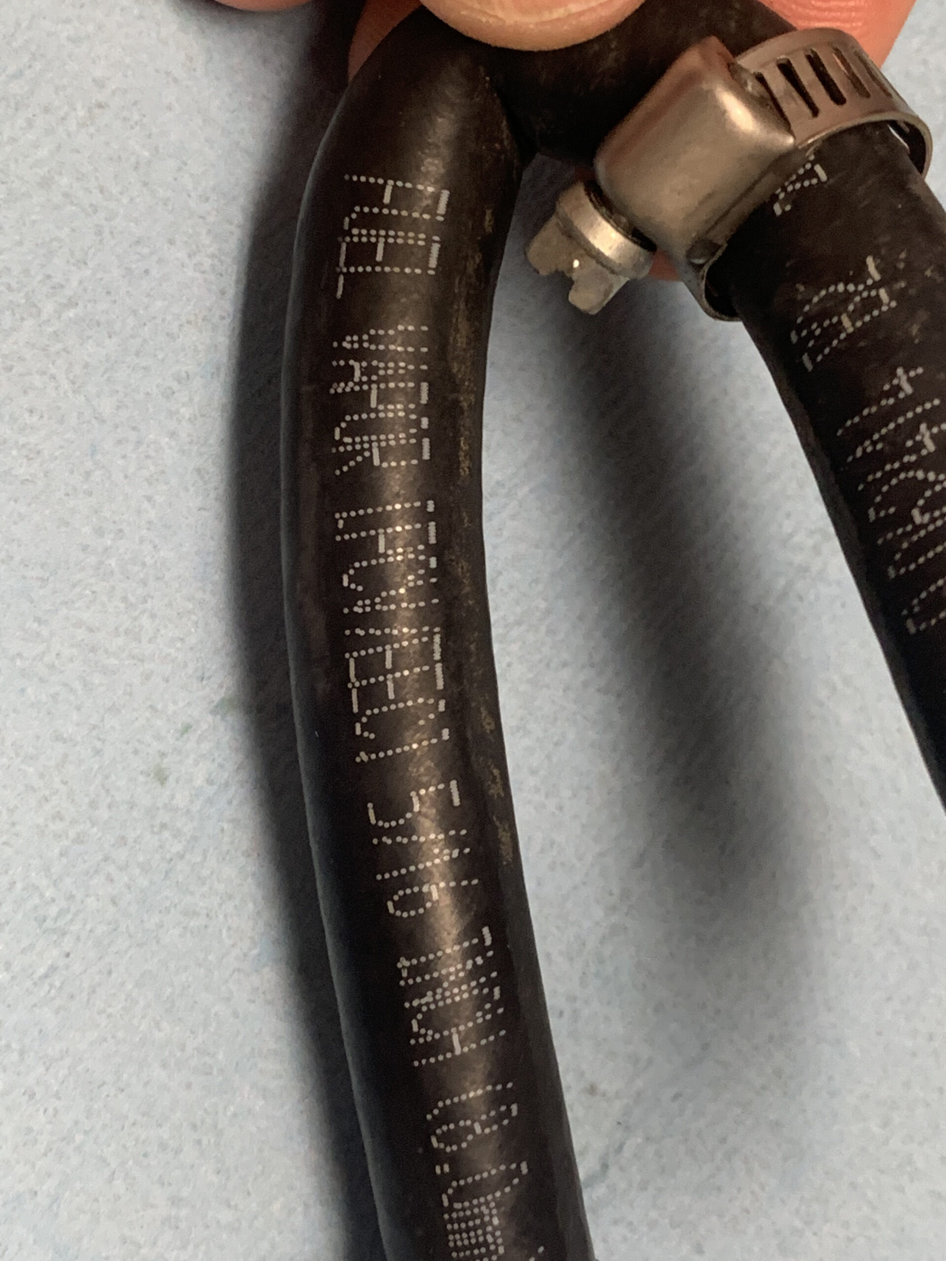
I left all of that alone and focused on replacing the rubber hose that connected the sections of pipe along with the fuel pump and fuel filter. 5/16″ high pressure fuel injection hose was used to replace the original 8mm hose. 12mm hose was used otherwise.
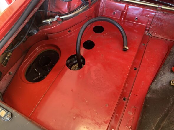
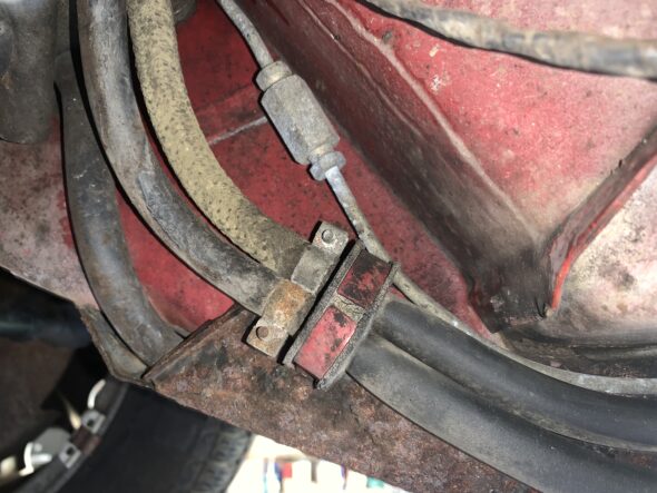
From the fuel tank, the delivery pipe and the return pipe exit the trunk bulkhead through two rubber grommets. There are two 4″ pieces of hose that link the trunk hard pipe to the hard pipe under the car.

Fuel Hoses from Trunk to Hard Pipes
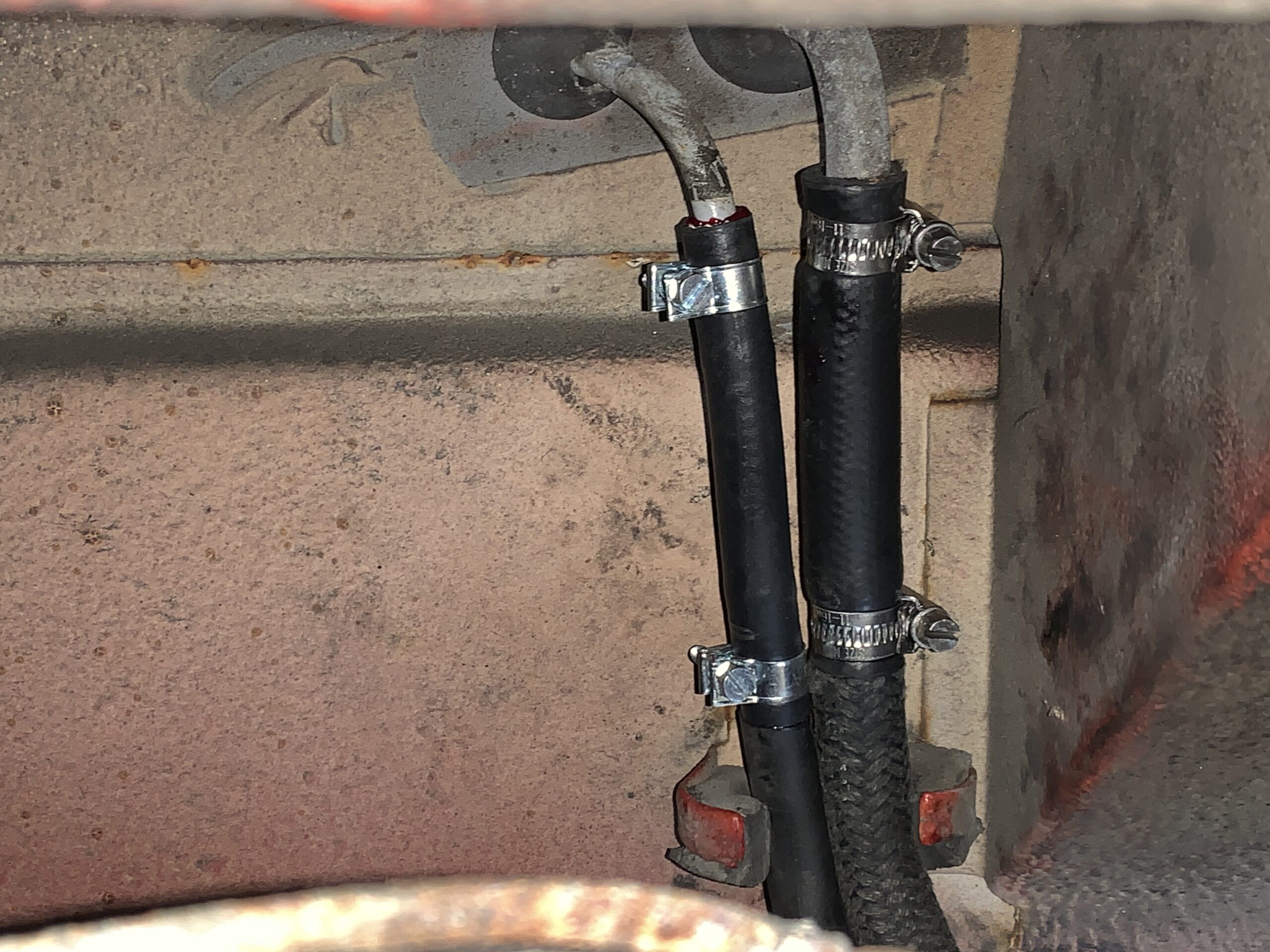
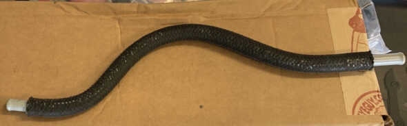
Continuing the progression of the routing from the rear to the front of the car, The delivery hard pipe is connected to the fuel pump with a section of rubber hose formed into an “S” shape with care taken to avoid any kinking of the hose. The braided hose was soured from Belmetric.
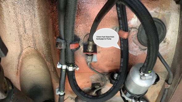
12mm Fuel Hose from hard pipe to Pump
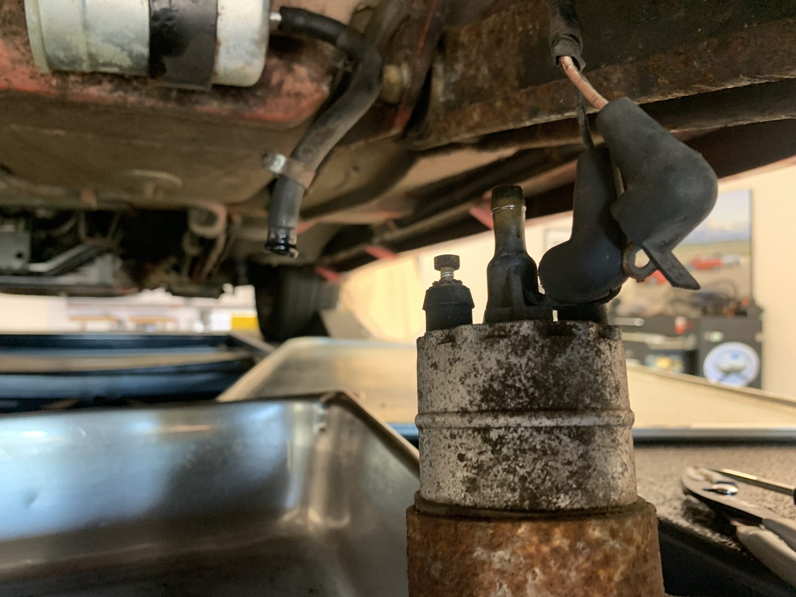
While in that location I removed the Bosch Fuel Pump as well as the bracket and rubber vibration isolators that secure the pump to the chassis. I cleaned up the pump and its electrical connectors, cleaned and painted the mounting bracket and replaced red the rubber isolators.
The pink and white wire that goes to the fuel pump is on the terminal with the 7 mm nut it’s rusted. The black ground wire goes to the larger nut that is brass colored.

Bosch Fuel Pump Electrical Connections
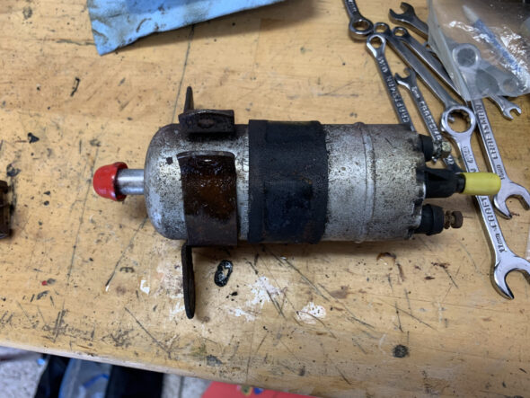
Bosch Fuel Pump with Mounting bracket
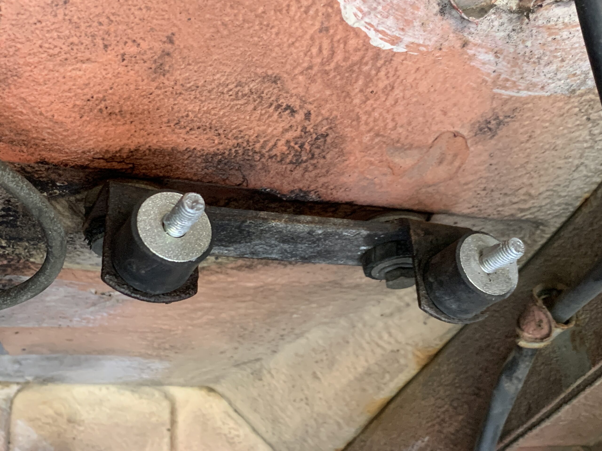
New isolators installed with stainless hardware M6-1.0.

Fuel Pump Bracket Rubber Vibration Isolators
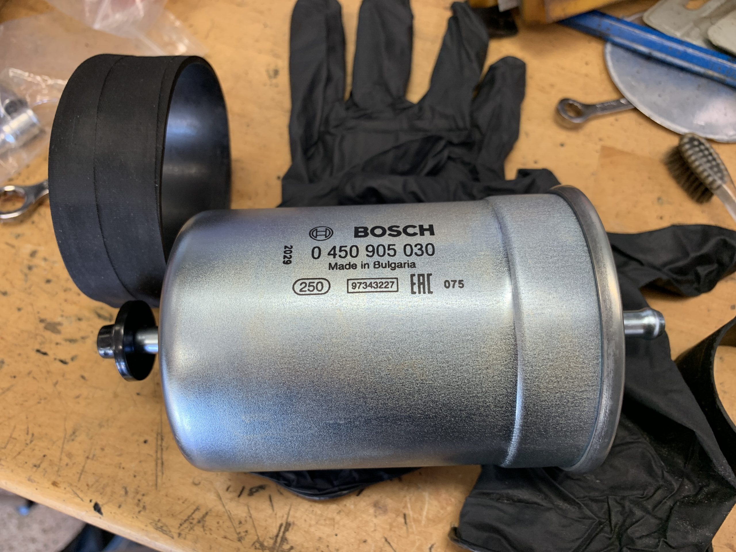
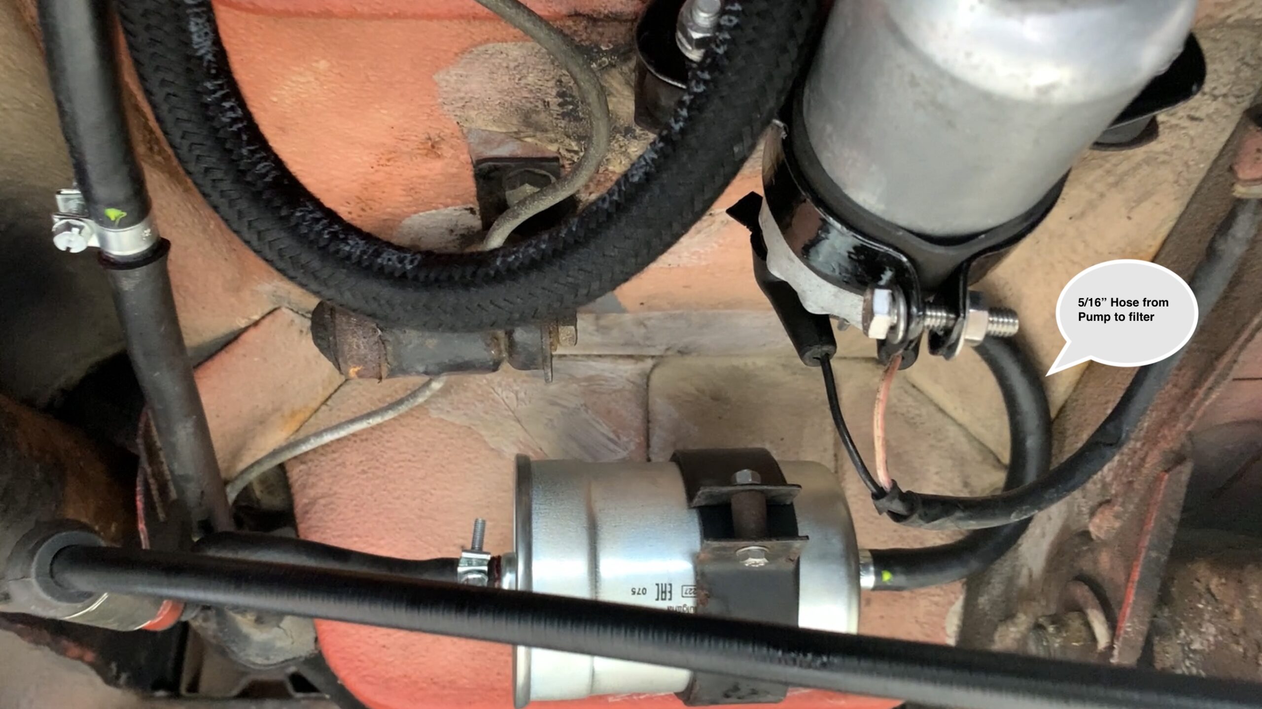
From the fuel pump a short piece of new 5/16″ fuel injection hose is used to connect to a new Bosch Fuel Filter.
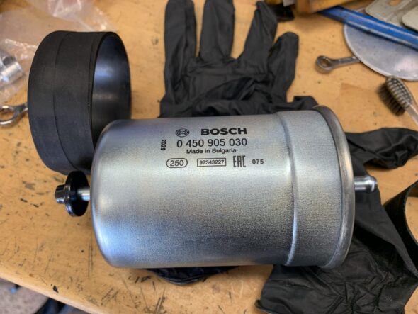
New Bosch Fuel Filter
The short hose from the fuel pump to the fuel filter is 8 inches long.

5/16″ fuel injection hose from fuel pump to Filter
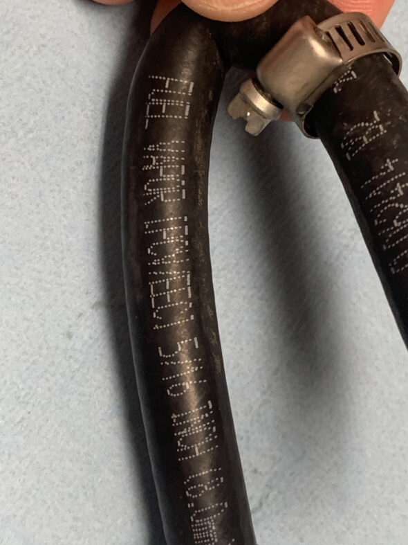
I could not find a piece of fuel injection hose that would make the bend from the fuel filter to the hard pipe without kinking, so I was forced to reuse the original hose that did appear to be in good condition. The original hose is 5 1/2″ long.
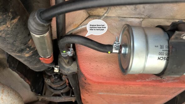
Original 8mm fuel injection hose from filter to hard pipe
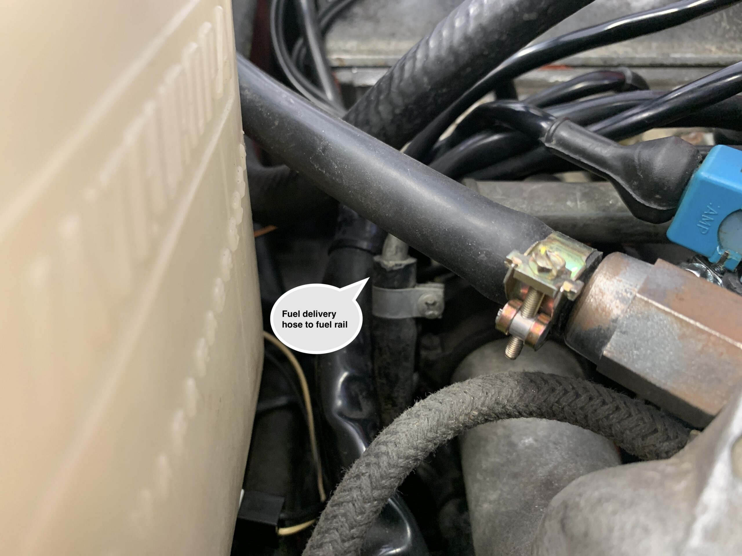
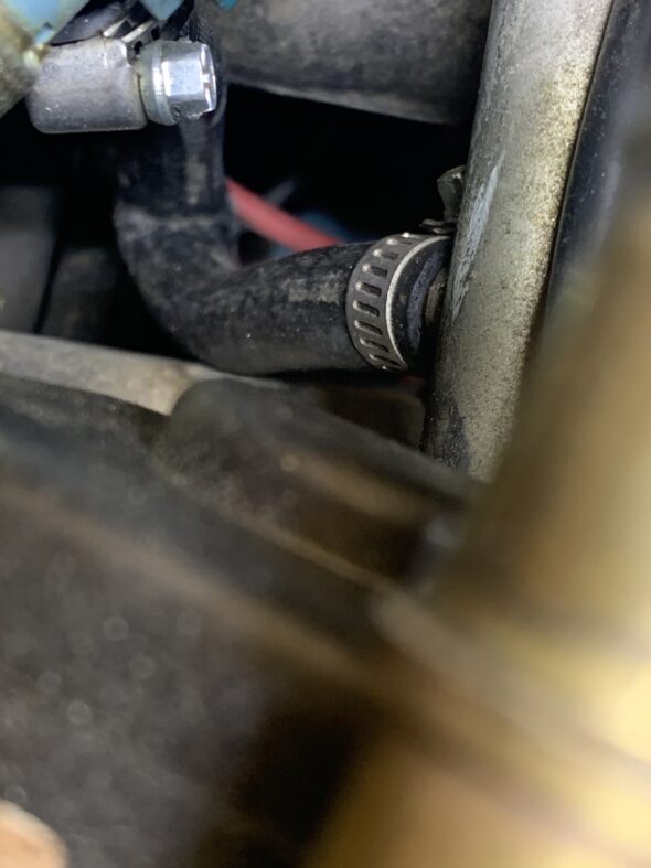
The last section of fuel delivery hose from the hard pipe to the fuel rail is 21″ long. At the junction by the chassis it appeared that this hose had never been changed given how the clip screws were oriented.
Union of hard pipe from fuel filter to the fuel injection rail
The hose connects at the rear of the fuel rail. Accessing the hose clip is easier if the windshield washer fluid tank is lifted out of the way.
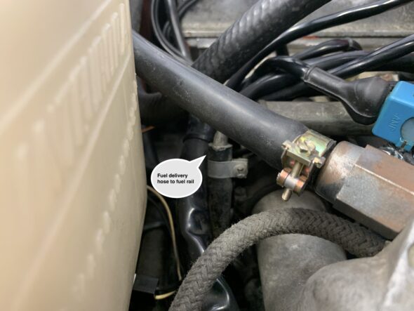
Fuel delivery hose to fuel rail
The fuel return line has a short section of hose linking two hard pipes near the union of the fuel filter/hard pipe. Again, this piece of hose is about 4″ long.
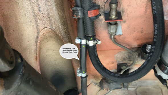
Fuel Return Line Short Rubber hose Linking Hard Pipes
The final section of return hose linking the hard pipe along the chassis rail to the bottom of the fuel pressure regulator is 37″ long. I installed a new Bosch Fuel Pressure Regulator.
The large nut on the fuel rail requires a 17 mm wrench. The small nut on the pressure regulator is 14 mm. The large nut on the bottom of the pressure regulator holding it to the fuel rail bracket requires a 21 mm wrench.
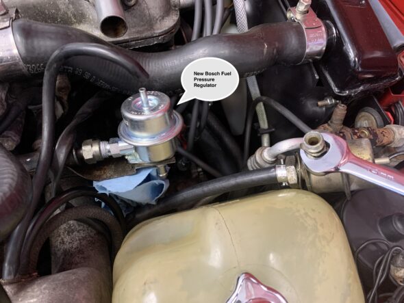
New Bosch Fuel Pressure Regulator
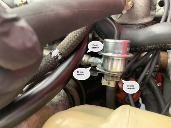
New Fuel Pressure Regulator Mounted
October 7, 2021
70,874 miles on the odometer
SIGNIFICANT FUEL LEAK AT COLD START INJECTOR
I had ordered parts and was getting ready to replace the major components of the fuel delivery system, but I was moving a little too late!
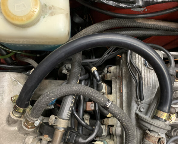
After a brief drive in the neighborhood I discovered that I had a significant fuel leak emanating from somewhere in the engine compartment. Today I disconnected the lead from the ignition coil to the distributor so I wouldn’t have any spark. I then had my lovely assistant Tabatha turn on the ignition and crank the starter to initiate the fuel pump. It appears that the fuel hose delivering fuel to the fuel rail had developed a leak.
Alfa Cold Start Injector Hose Leak
The cold start injector had been replaced several years ago. When it was done the installer used a section of hose that was too short resulting in a severe kink in the hose.
The next step was to clear some other hoses and components to ease access to the fuel hose in question. Moving the windscreen washer bottle out of the way makes things much easier. I then removed the compromised hose and replaced it with a new 5/16 inch high-pressure fuel injection hose.
I discovered that he also failed to use fuel injection hose and instead used PCV emissions hose – not a good thing to do!
PCV Emissions Hose
This was the result:

PCV Emissions hose failure
The distance between the cold start injector and the fuel rail is only a few inches. The previous installer had used an 8″ piece of hose that had kinked, so I used about a 12″ piece and achieved a rounded delivery free of kinks. It is not an easy job to get the hose and its clamps onto the fittings, but after some struggles everything was in place. We tried cranking the starter and had no fuel leaks!
I then reattached everything that had been cleared out of the way, reconnected the coil, and took Alfie for a test drive. No leaks and the car ran well. In fact, I believe it started easier than normal, probably attributable to an an unobstructed fuel hose.
April 28, 2021
70,815 miles on the odometer
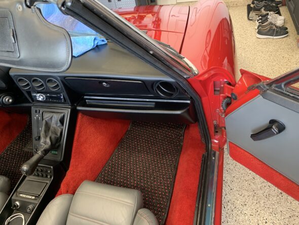
DOOR SEAL AND RH DOOR CAP REPLACEMENT
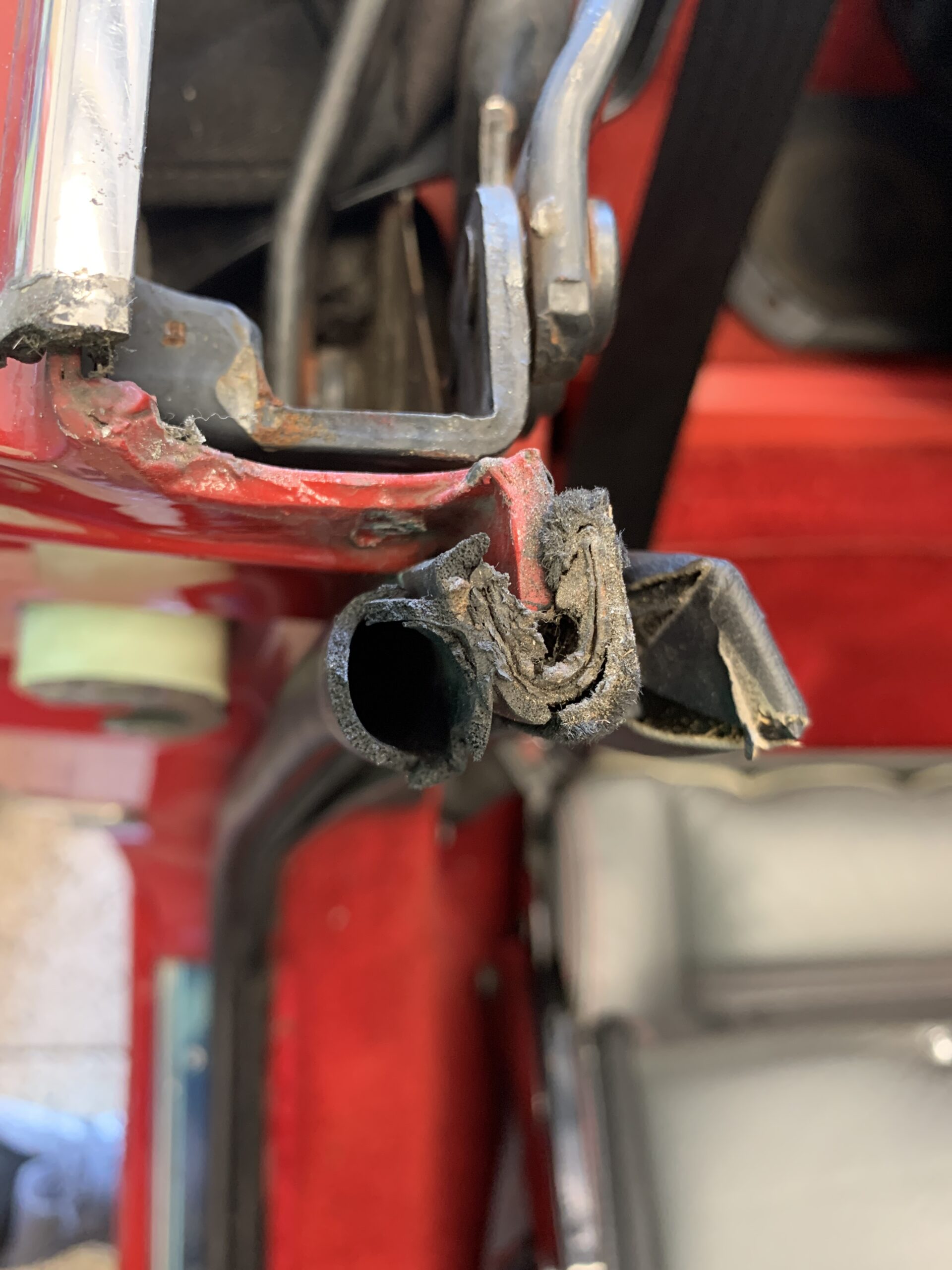
The door seals on the car are torn and discolored so I ordered replacements from Classic Alfa. The new seals are very similar to the originals. The two photos below show the discoloration and seal tear:
Discolored door seal
Torn Rubber Door Seal
The first step in the removal of the old seals was to remove the inner plate that holds the seal to the sill threshold. It is held in place with four phillips head screws. The rear of the plate lines up exactly with the rear of the outside threshold plate. Unfortunately, the front screw on the driver’s side had been broken off previously.
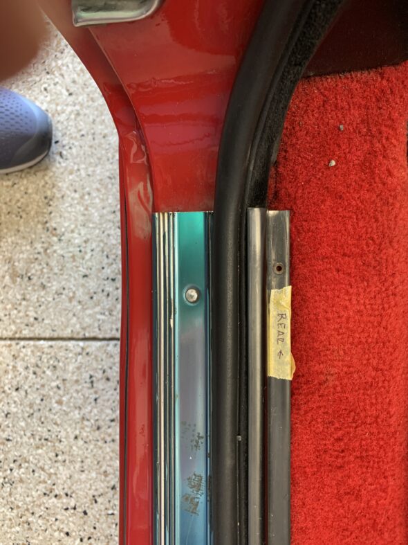
Seal Inner Securing Plate
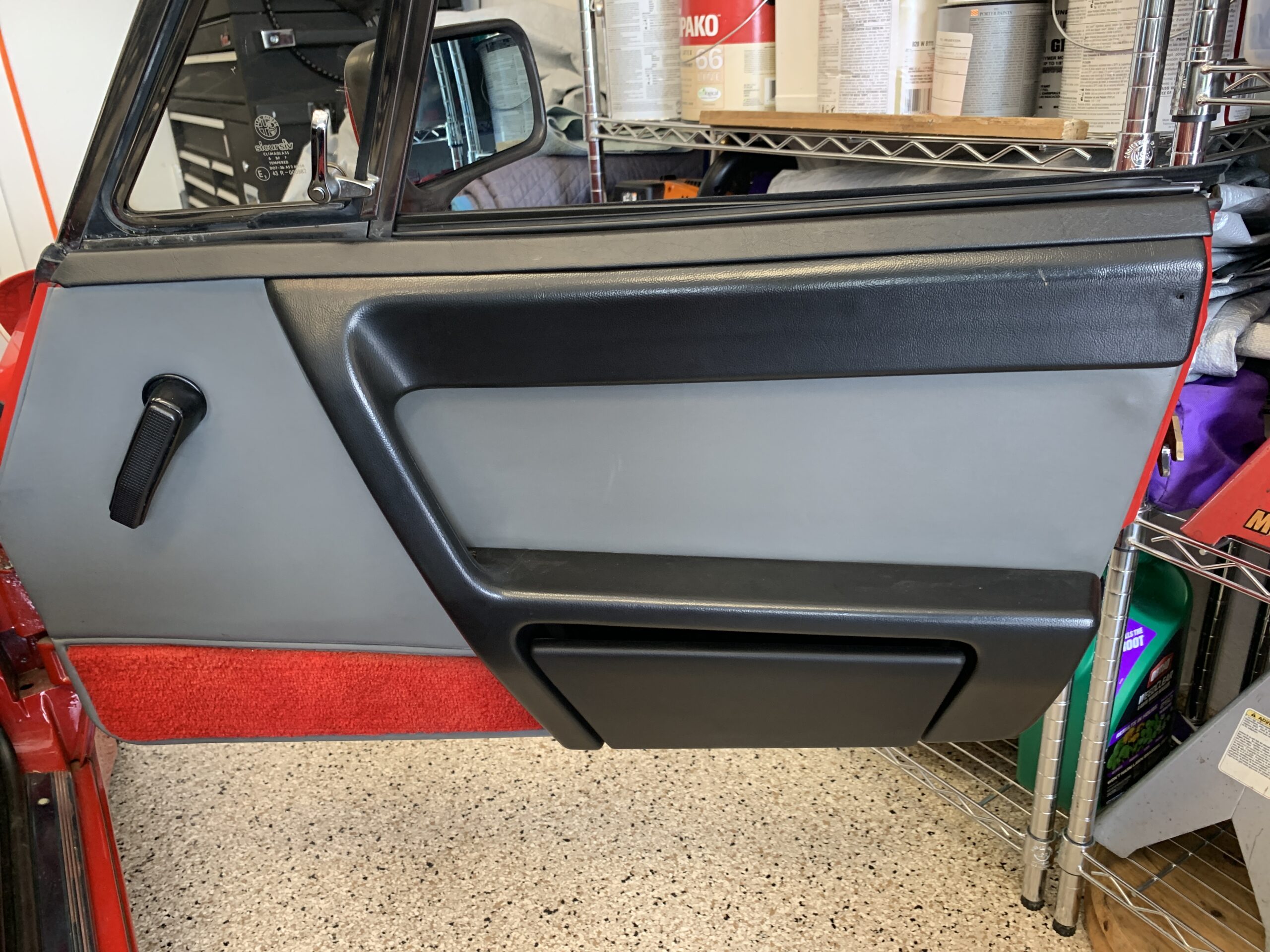
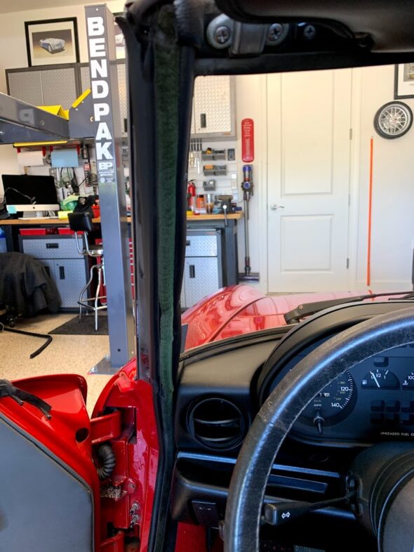
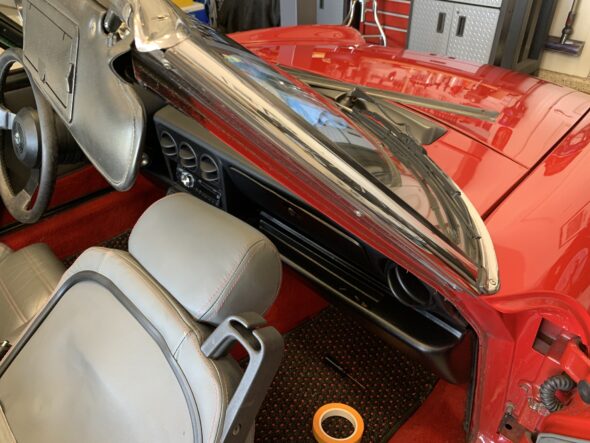
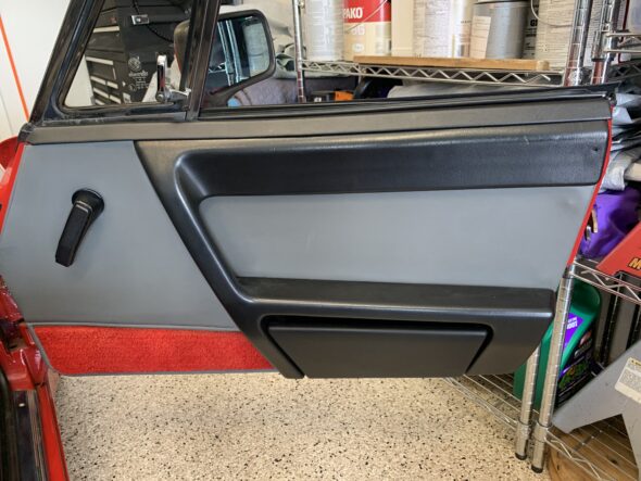
The next step is to remove the B column vinyl trim piece that retains the seal. It has four Phillips head screws. The panel on the driver’s side is slightly different because it houses the trunk and gas filler pulls. The panels had been tampered with before and are not in great shape. I have ordered replacements. In both cases, the panels do not need to be completely removed – just loosened so that the seal can fit under or next to the panel.
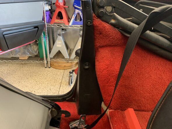
RH B pillar trim panel

RH B pillar trim lower fastening screw
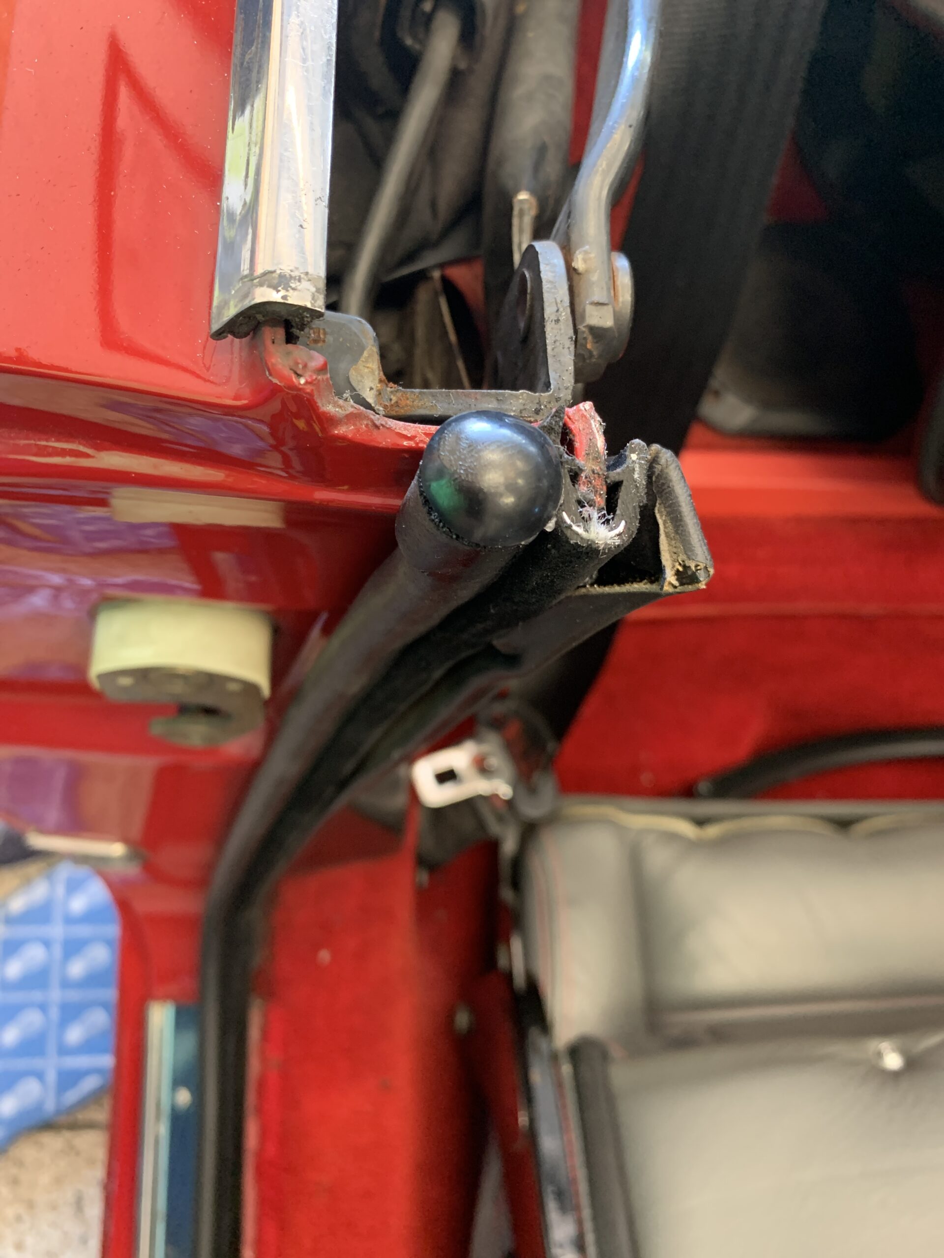
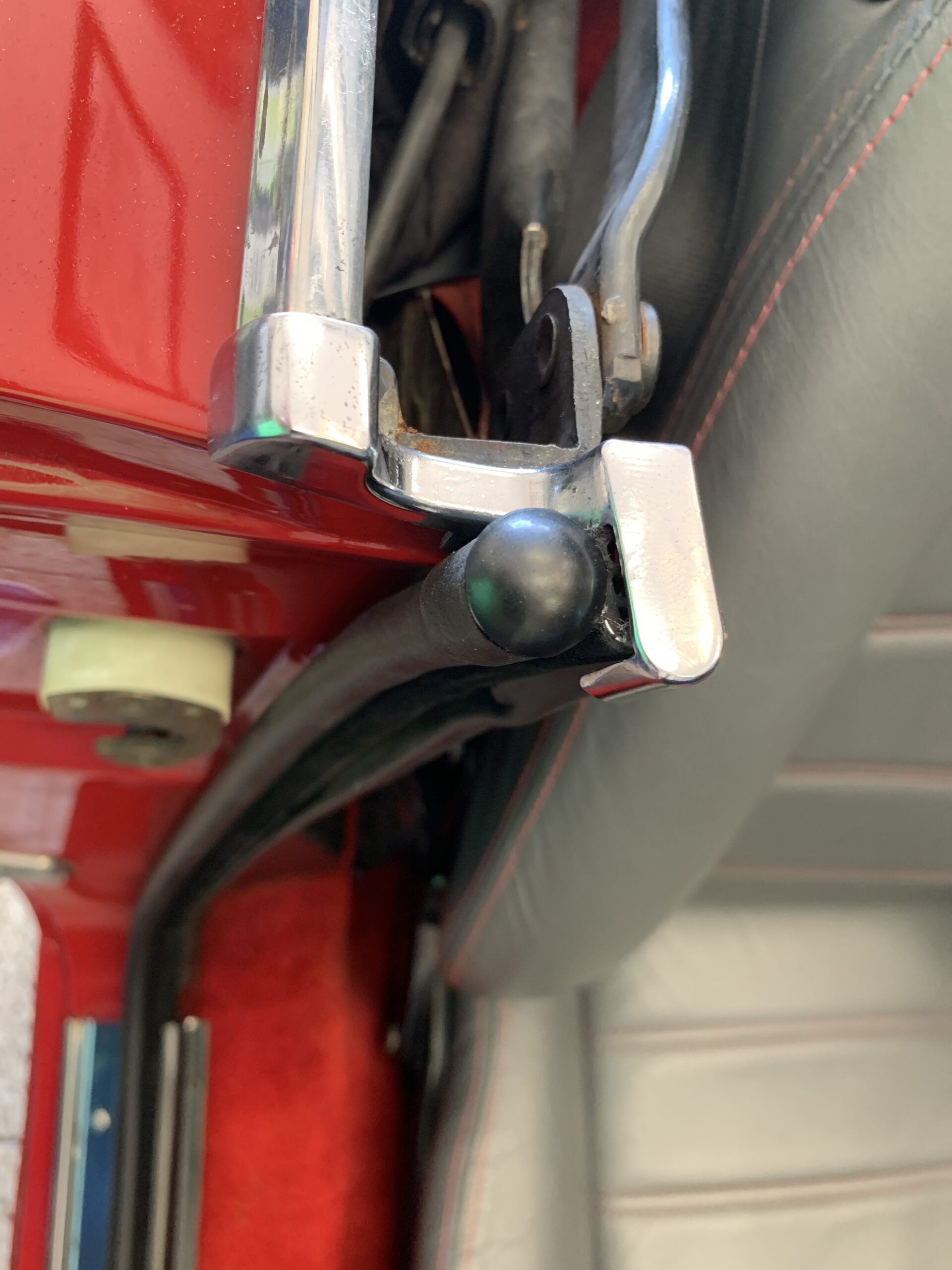
The next step was to remove the chrome trim cap on top of the door seal. This is held in place by only one Phillips head screw.
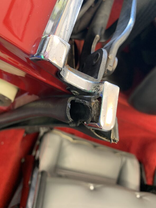
Chrome Trim Cap with Securing Screw
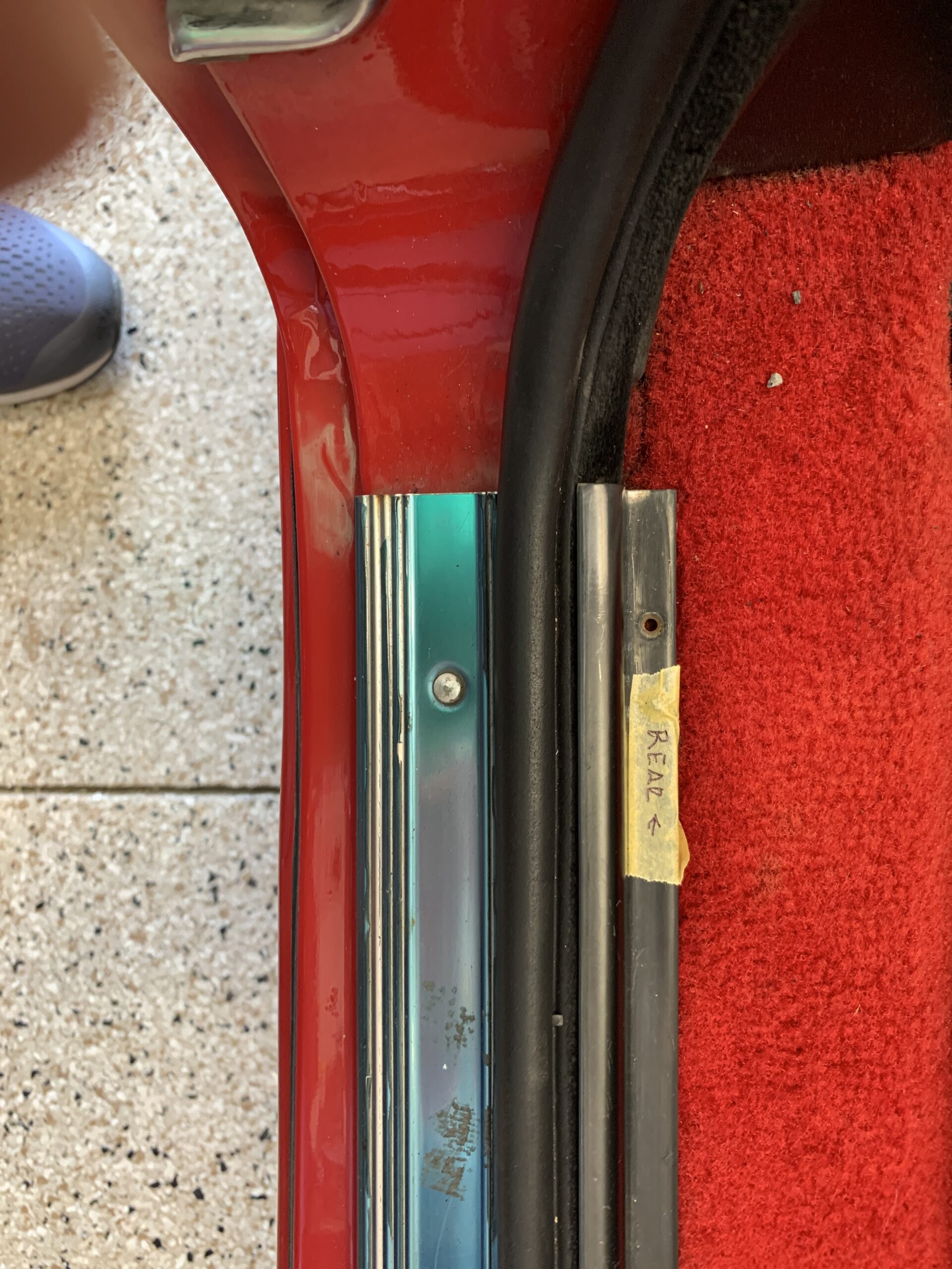
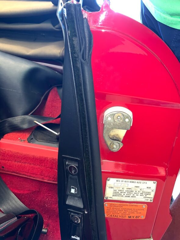
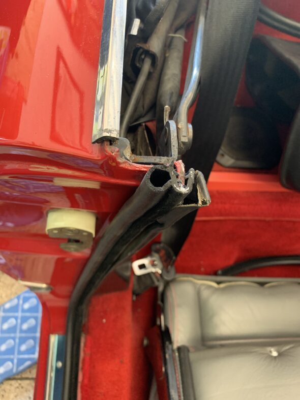
Access is then gained to the rear termination of the door seal.

Rear termination of Seal
The old seal can then be pulled away from the car. This photo shows the lip the seal grips when replaced:
Seal Mounting Lip
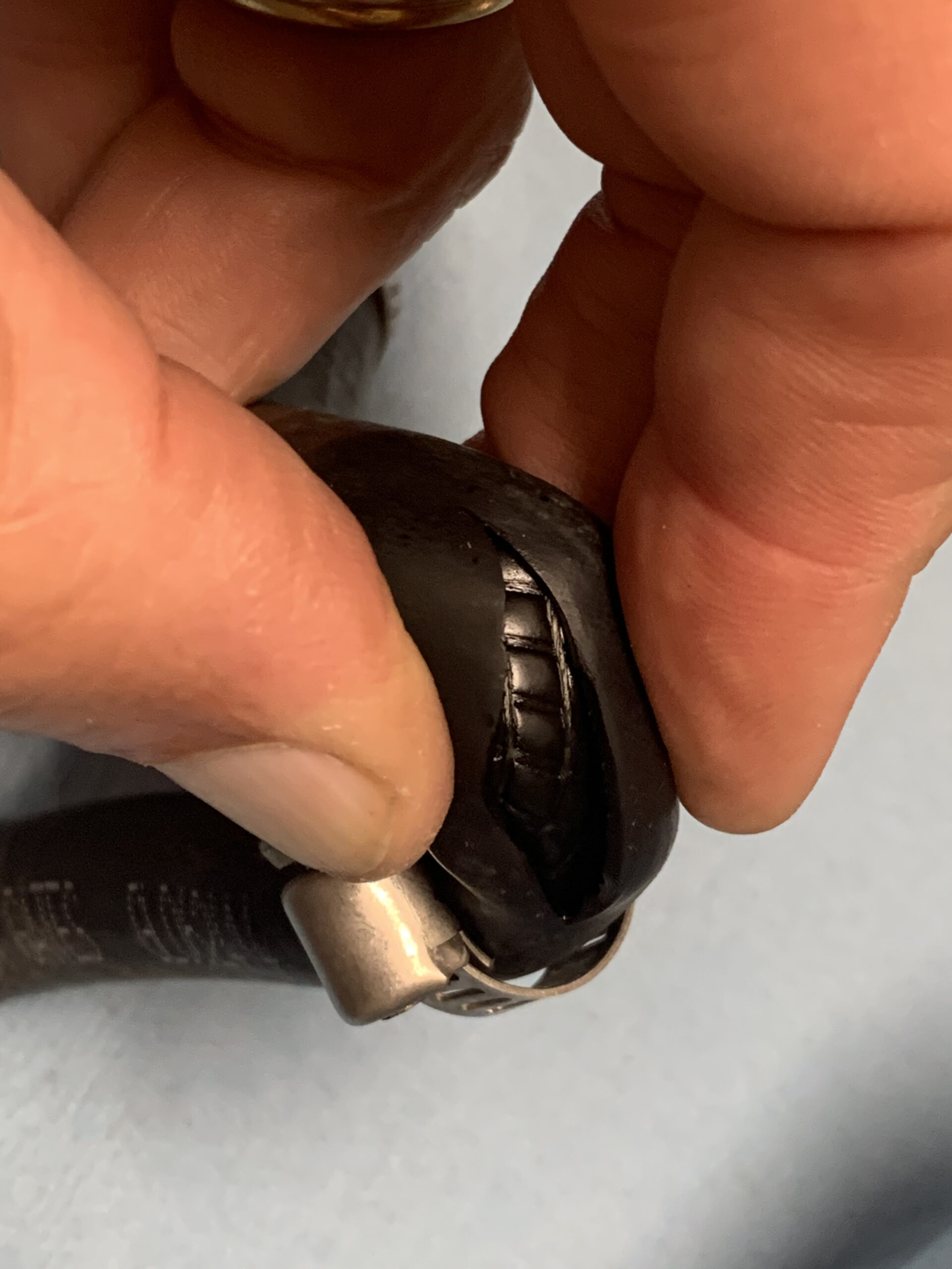
After installing the seal in the door, I screwed the trim panels back in place and cut the rear terminus of the seal with a hacksaw blade. Then installed the little rubber plug and replaced the chrome trim.
Cutting the Seal to Length
There is a rubber plug that fits into both ends of the seal to prevent water from entering the rubber tube. These were also sourced from Classic Alfa. I used a little rubber grease to make it easier to push the plugs into the seal ends.
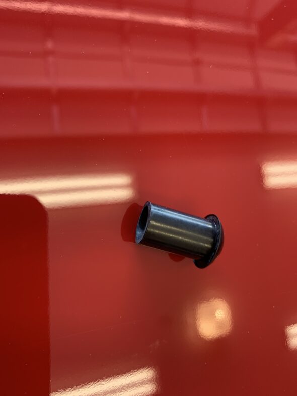
Rubber Plug for Seal

Seal Plug in Place
Chrome Trim Cap and Inner Seal securing plate screwed back in place

Chrome Trim Cap Back in Place
RH Side Seal Installed
The RH door capping was broken and I ordered a replacement from Classic Alfa. The replacements are metal rather than plastic so they should hold up much better. I just tapped the capping into the six metal clips with a light rubber hammer. The finished product looks much better than the broken piece!
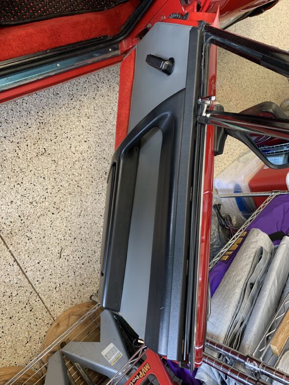
Door Cap Replacement
Door Cap Replacement
April 13, 2021
70,787 miles on the odometer
VACUUM HOSE AND HOSE CLAMP REPLACEMENT
Original Romablok hose clamps don’t seem to be produced anymore. I did find a source for reproduced clamps that are very similar to the originals and are stamped romablok at Jens Putzier Tools in Germany. The clamps appear to be of slightly lighter gauge steel and they have hex head machine bolts (a good thing) rather than the original cheese head round screws. They have a yellow zinc finish. I ordered a variety of sizes of the clamps and used them to replace many of the clamps on hoses under the hood. I will also replace the fuel hose clamps under the car when I replace the hoses. More detailed information about the original Romablok clamps can be found in a previous post: https://valvechatter.com/?p=12820
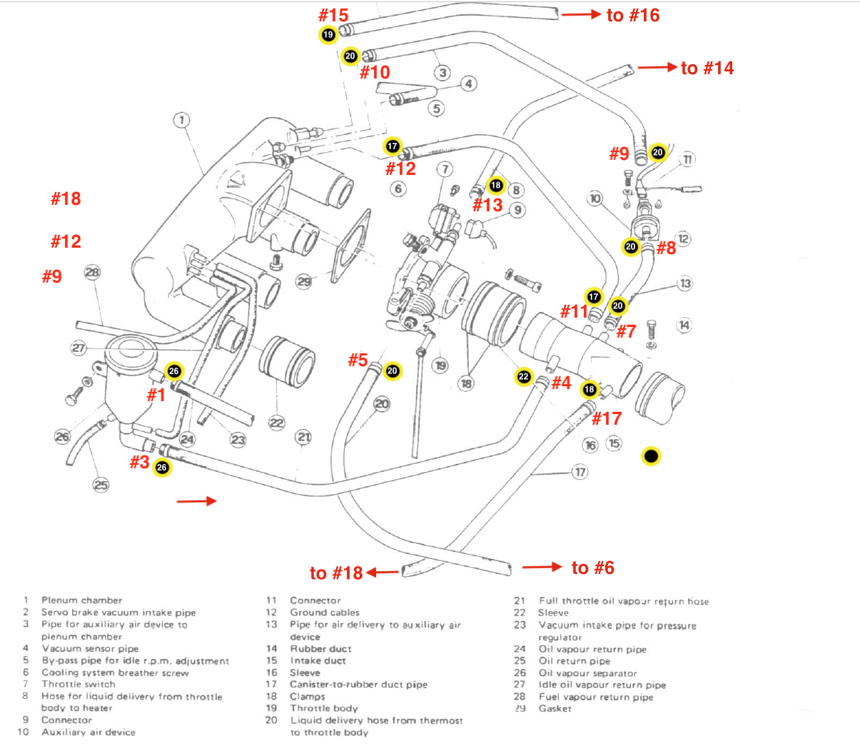
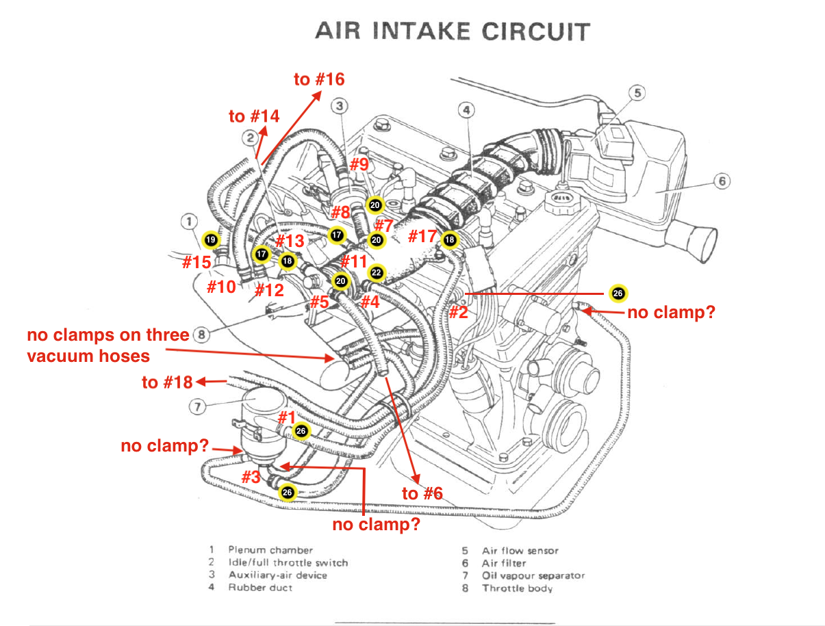
The Spider has a number of vacuum hoses associated with the L-Jetronic Fuel Injection system. These all seems to be functioning just fine, but I expect many are original and are showing their age. I thought it time to replace many of these hoses before failure and to dress up the appearance of the engine. I did not replace all of the hoses yet. My plan will be to replace those that are somewhat hard to access when I get around to pulling the intake plenum for a clean up. On my list for the future.
I decided to use silicone hoses to replace the old vacuum hoses and sourced them from HPSI Motorsports. They make a very nice kit that contains all of the various sizes required for the Alfa Spider and also provide a helpful set of directions making the job quite easy.
Plenum to Auxiliary Air Device – Silicone Hose “F” with two 20-23mm Romablok clamps.
Plenum to Auxiliary Air Device
Air Intake to Auxiliary Air Device – Silicone hose “F” with two 18-20mm Romablok clamps.
Air Intake to Auxiliary Air Device
Plenum to Brake Booster – Silicone hose “A” with a 16-16.5mm Romablok hose clamp at the check valve and a 17-19mm Romablok hose clamp at the booster fitting.
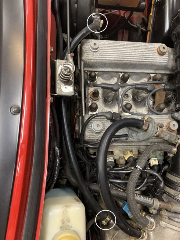
Plenum to Brake Booster
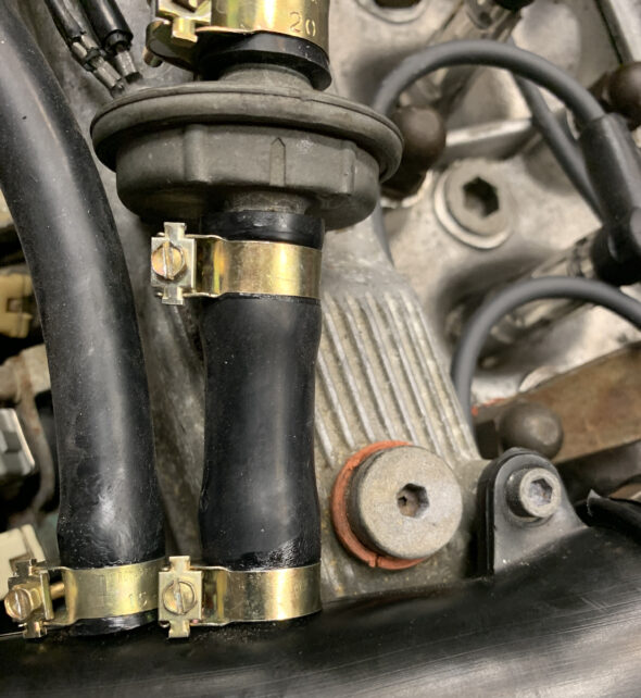
Idle Speed Adjustment Port at Plenum to Air Intake Pipe – Silicone Hose “F” with a 13-14.5mm Romablok hose clamp at the Idle Speed Adjustment Port and a 15-16.5mm Romablok hose clamp at the Air Intake Pipe.
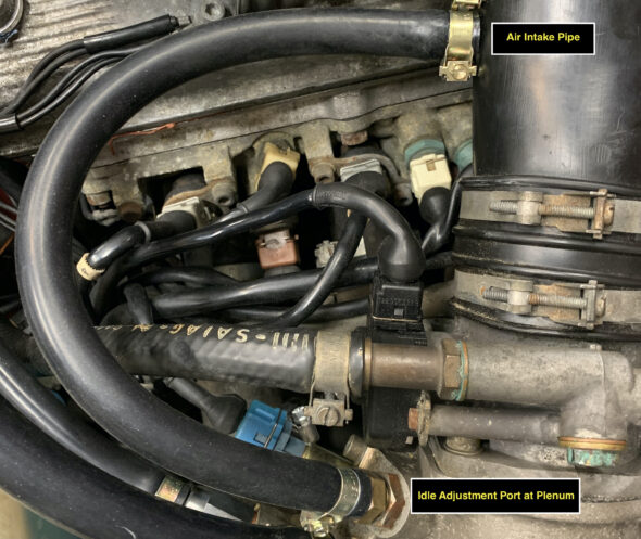
Idle Adjustment at Plenum to Air Intake Pipe
Rocker Cover Breather Port to the Oil Vapor Separator (OVS) – I did not replace the hose at this time, but I did replace both hose clamps with 24-27.5mm Romablok hose clamps.
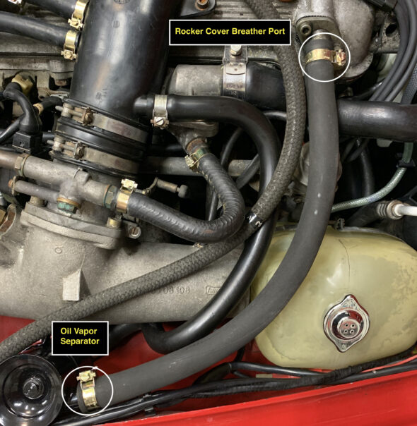
Rocker Cover Breather to OVS
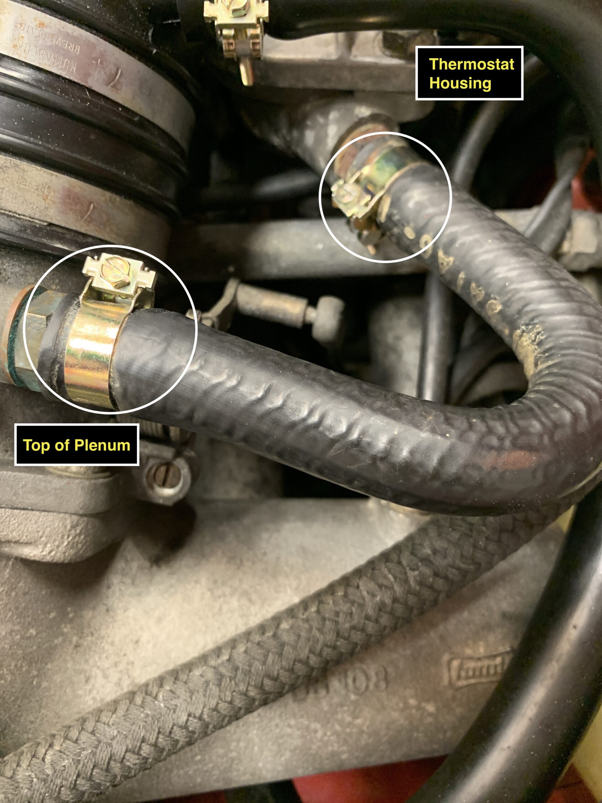
Coolant Hose from Thermostat Housing to the Top of the Plenum – I did not replace the hose at this time, but I did replace both hose clamps with a 17-19mm Romablok Hose clamp at the Thermostat Housing and an 18-20mm Romablok Hose clamp at the top of the plenum.
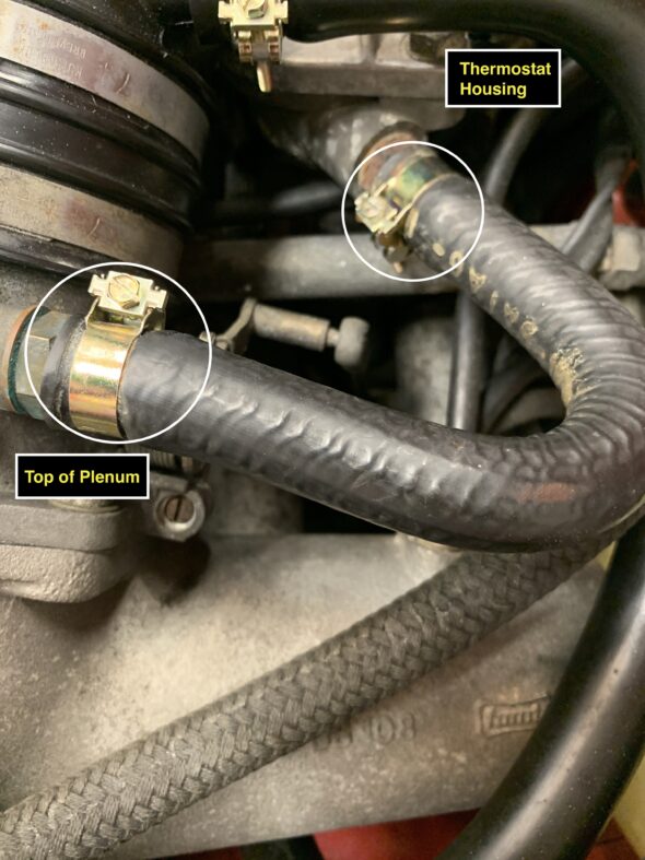
Coolant Hose from Thermostat Housing to Plenum
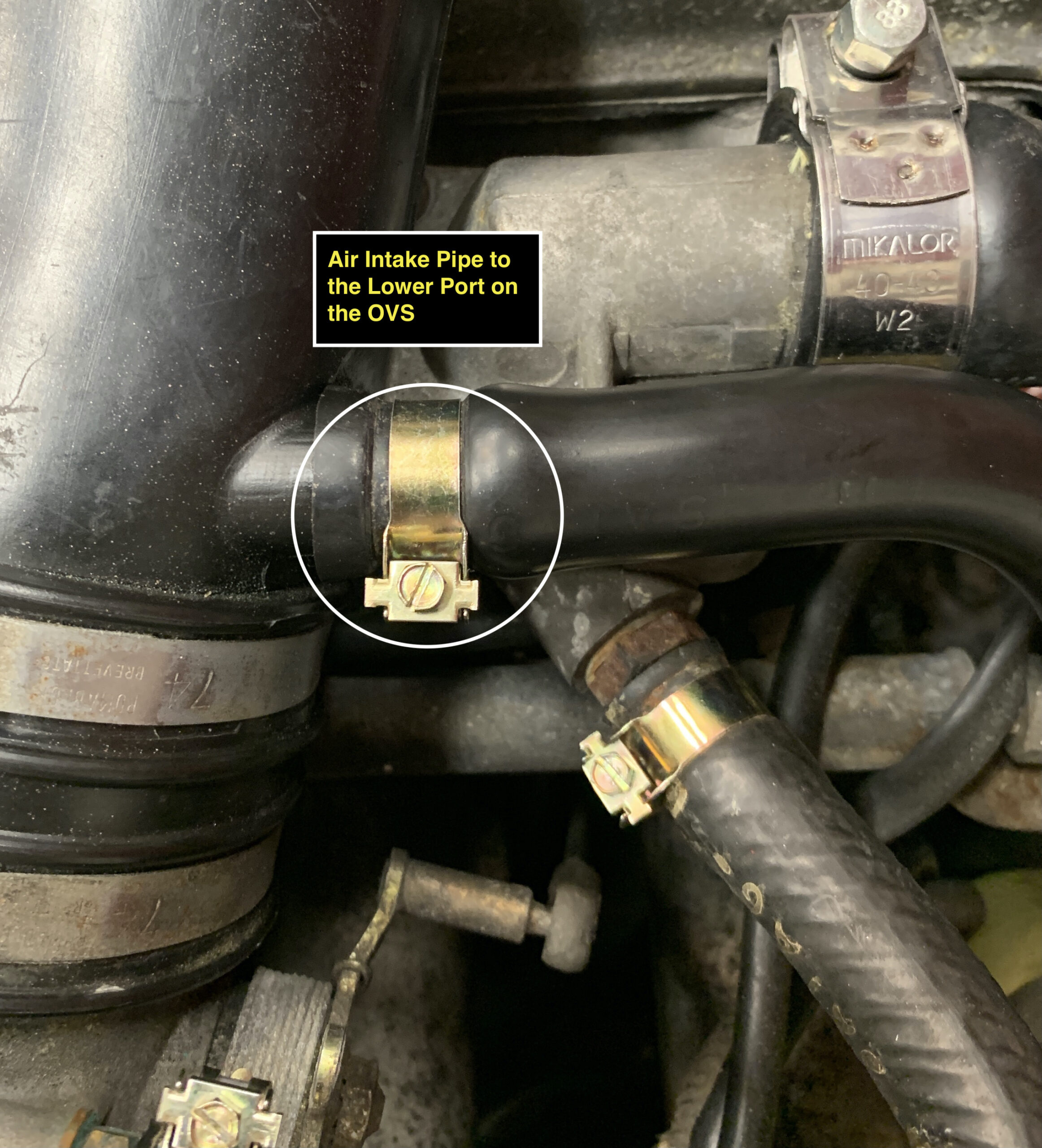
Air Intake Pipe to the lower port on the OVS – I did not replace the hose at this time, but I did replace the original 22mm Romablok Hose clamp with a new 18-20mm Romablok Hose clamp at the Air Intake Pipe. I left the original clamp on the lower port of the OVS and will replace at a later date.

Air Intake Pipe to the lower port on the OVS
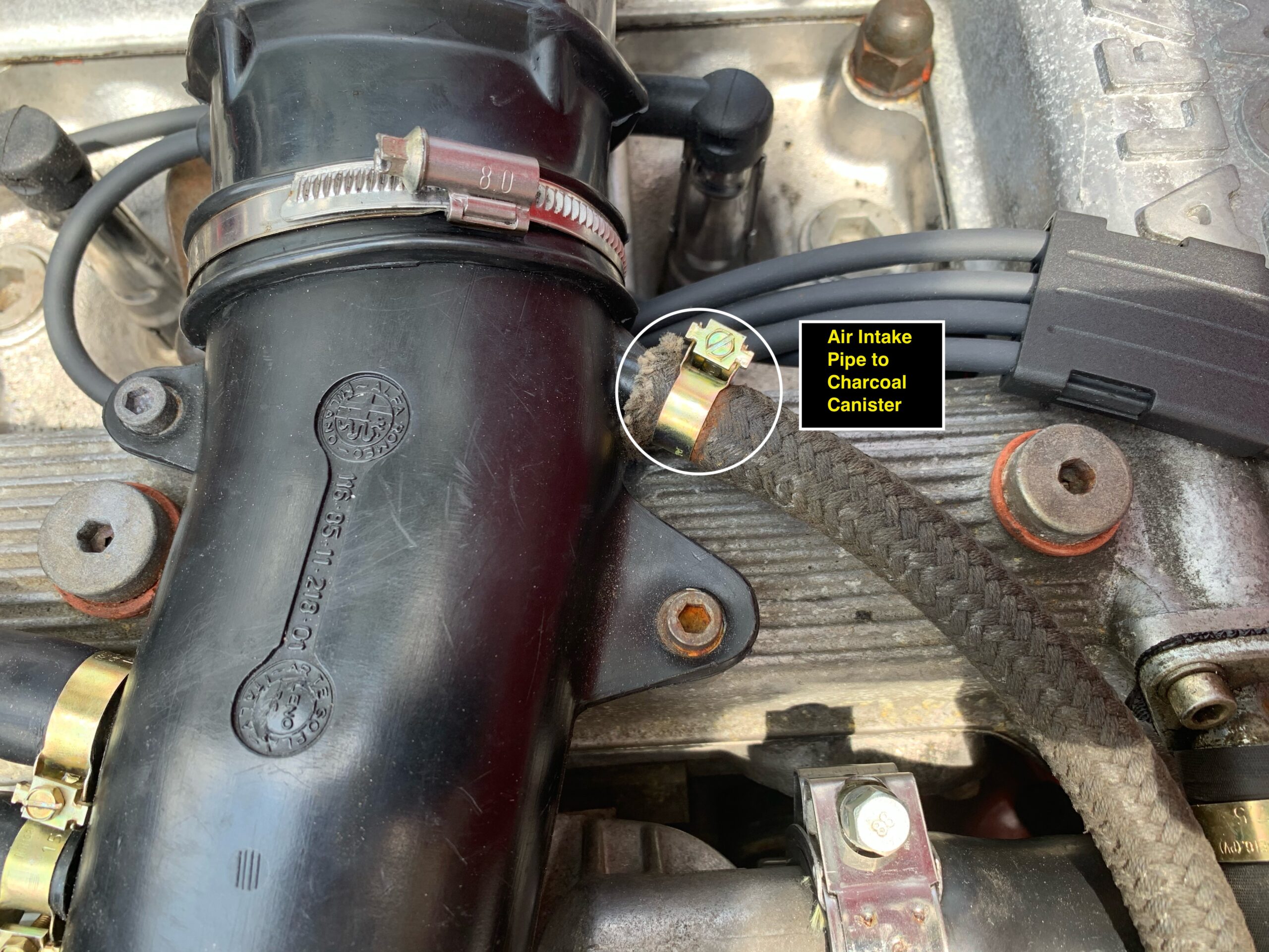
Air Intake Pipe to the Charcoal Canister – I did not replace the hose at this time, but I did replace the hose clamp at the Air Intake Pipe with a 17-19mm Romablok Hose clamp.

Air Intake Pipe to Charcoal Canister
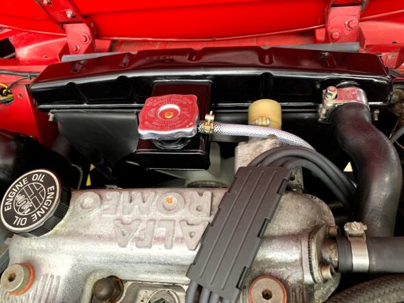
Coolant Overflow Hose to the Overflow Tank – I replaced the coolant hose for the radiator overflow port to the overflow tank and used a new 12mm Romablok Hose clamp at each end of the hose. The braided, clear hose was sourced from Classic Alfa.

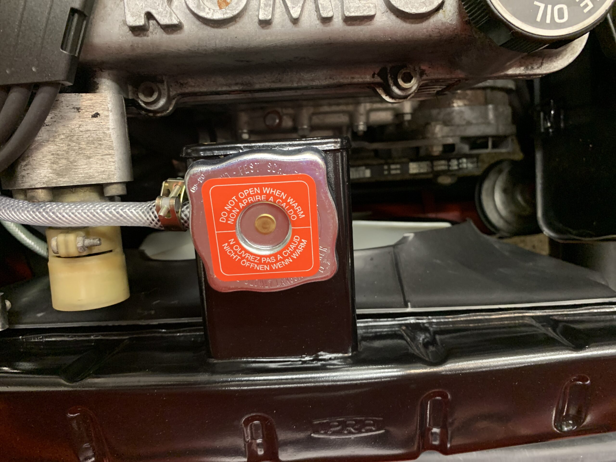
New Radiator Tank Cap and Overflow hose
This image shows an overhead view of the “upgraded” appearance of the engine bay with many new hose clamps installed. While I was at it I also added the warning decal for the radiator cap, also sourced from Classic Alfa. Now I need to clean that hideous overflow tank!
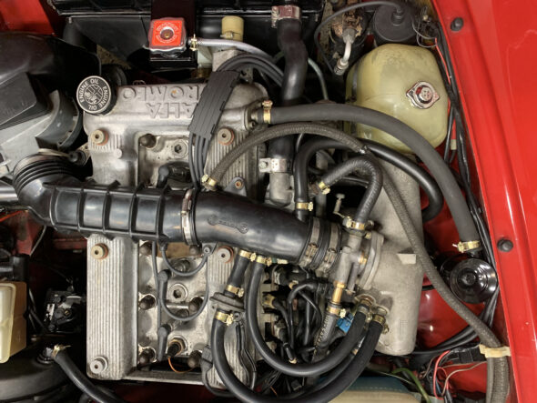
Overhead View of New Hoses and Clamps
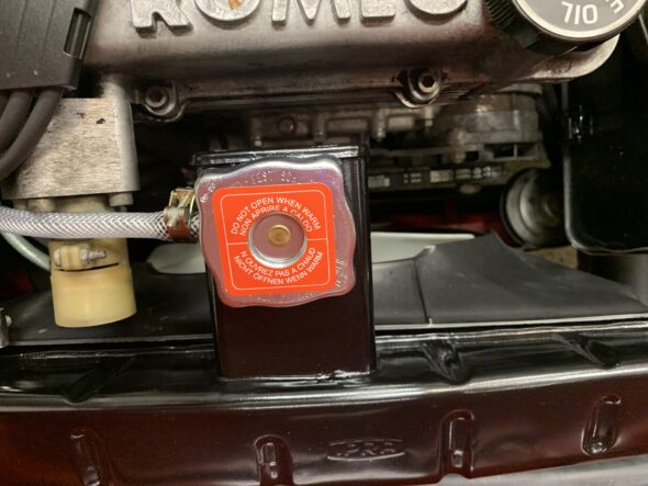
Radiator Cap Warning Sticker
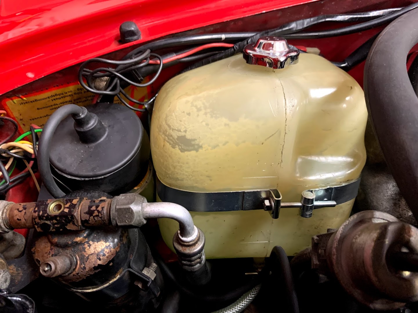
I ordered a new coolant recovery tank and mounting strap rom Classic Alfa to replace my discolored tank and tired strap. Unfortunately neither fit! I will give cleaning the tank a try but I was able to shorten and reshape the new strap so that I could use it with the original tank. At least the strap looks better now!
The problem with cleaning, replacing or replacing with new items is that they make older components look even worse. Note the air conditioner drier below. It definitely needs some love.

Coolant Recovery Tank Strap
April 5, 2021
70,752 miles on the odometer
RADIATOR REPLACEMENT
The original radiator was leaking around the lower lip of the upper tank. I pulled it out and took it to Sarasota Radiator Service, Inc., a local “old school” repair shop. Ron pointed out the very small white specs at the top of the core, next to the tank which are apparently tell-tale signs for solder joints going bad. We could have tried resoldering the unit as it was but instead decided to go ahead and order a modern core and installed it. Everything was accomplished in seven days.
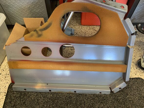
I sanded the tanks to remove the marginal paint that was on the radiator, primed and repainted it in gloss black. I then reinstalled the radiator in the car with a new fan shroud. The car, as I received it, did not have a shroud mounted. The shroud certainly makes the installation process a bit awkward and tedious but all was accomplished.
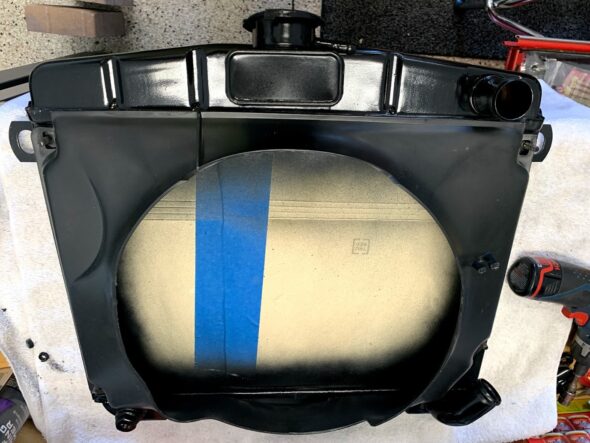
Alfa Fan Shroud
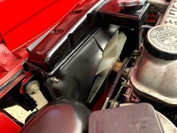
Radiator and Fan Shroud Installed
The air conditioner drier (air conditioning was an aftermarket dealer installed item) also made installing the upper right radiator mounting bolt a real pain to get to! The lower radiator hose clamp is also quite hard to access, but with considerable patience all was buttoned up.
I then installed a new radiator overflow hose to the coolant expansion tank and used a couple of new 12mm Romablok hose clamps. I also installed a new radiator cap sourced from Classic Alfa. I have taken the car for several runs making sure the car was under driving temperature. All seems well. The car runs at 175 degrees and I am experiencing no leaks.
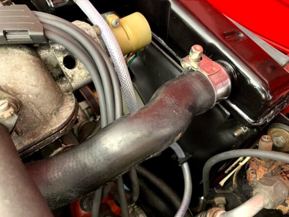
Overflow hose and Upper Radiator Hose with Mikalor Clamp
New Radiator Tank Cap and Overflow hose
March 22, 2021
70,750 miles on the odometer
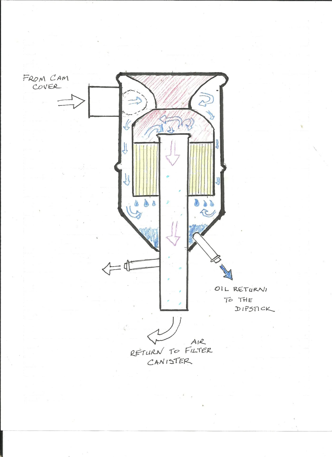
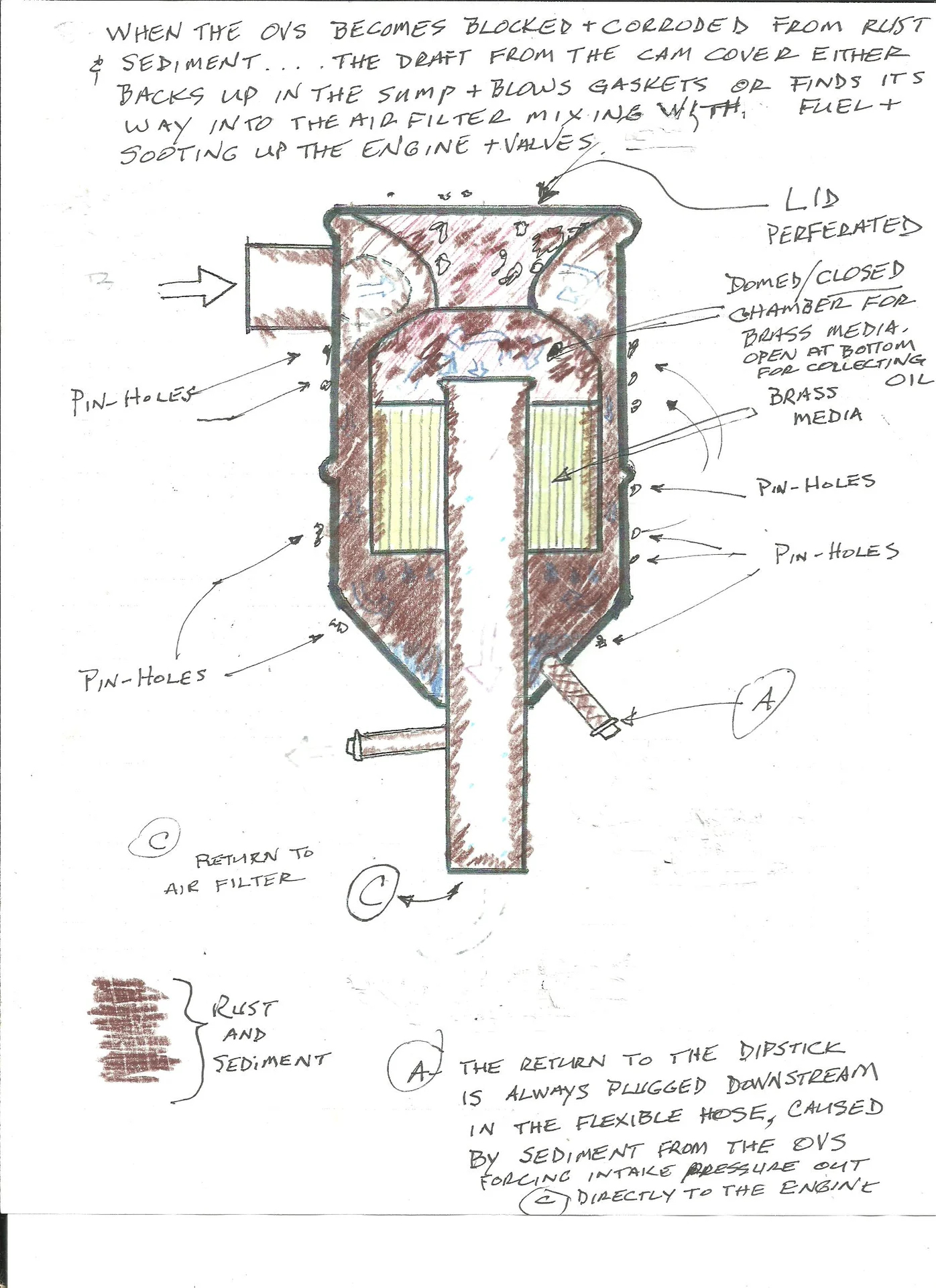
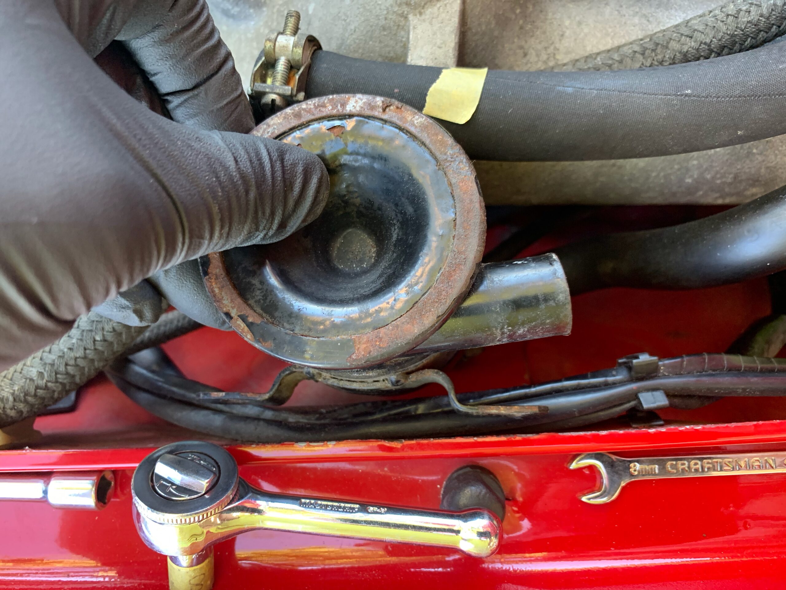
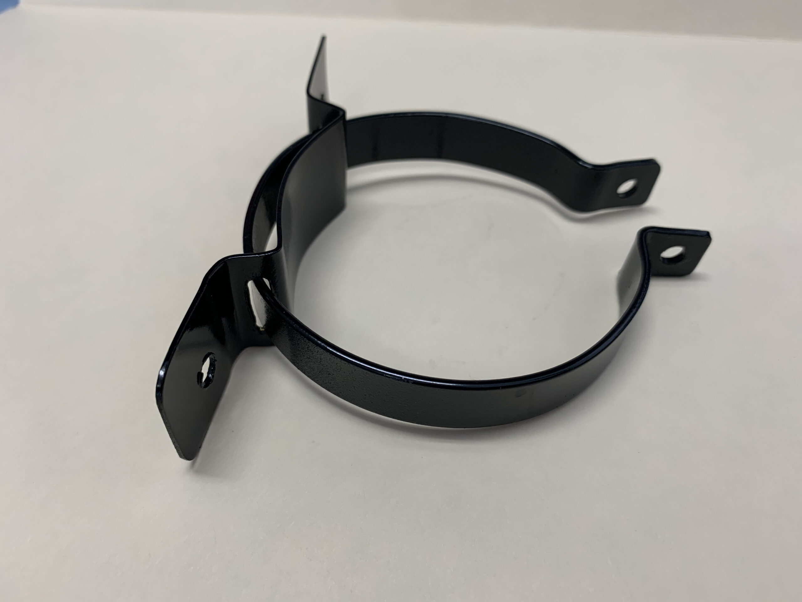
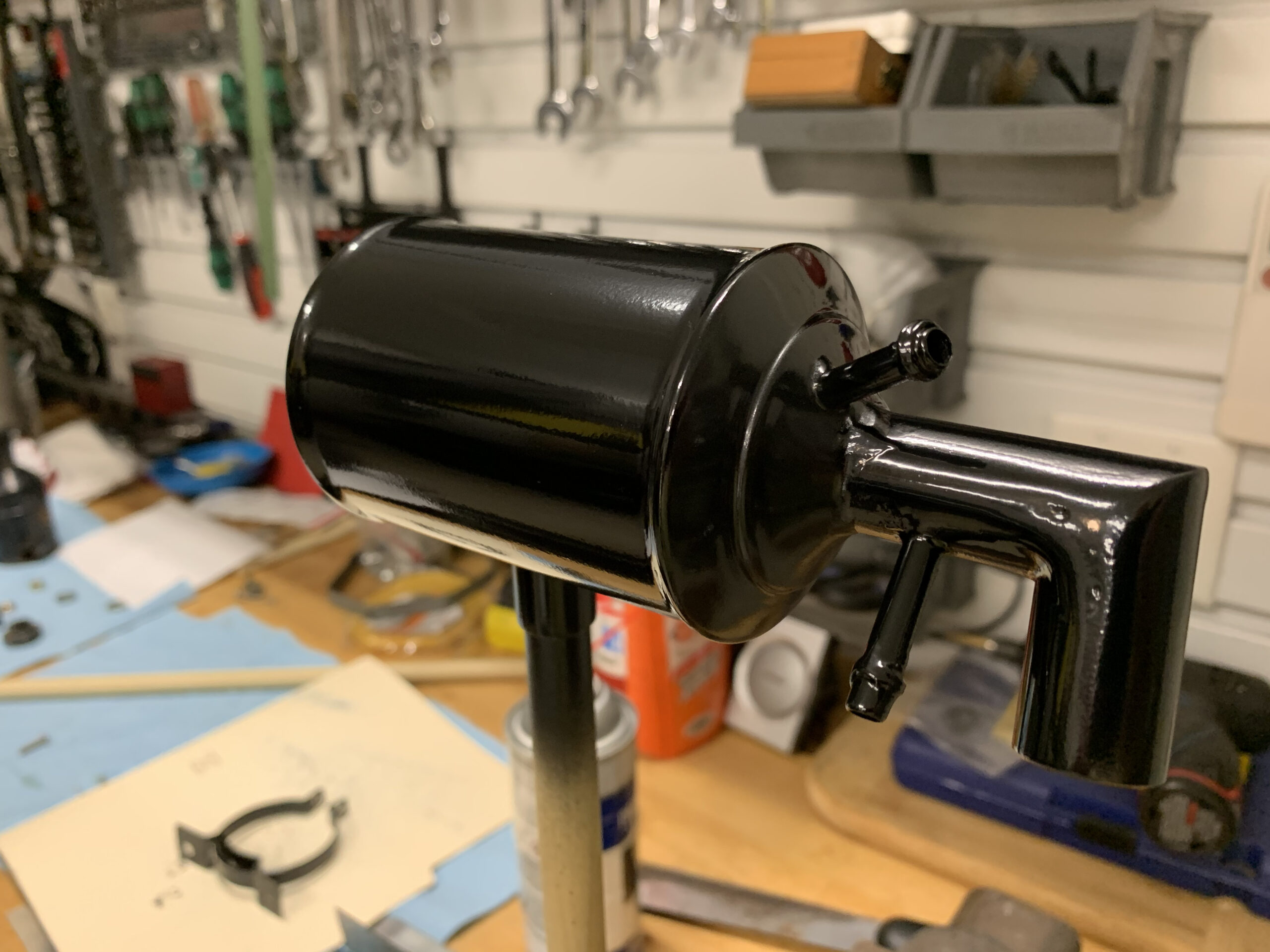
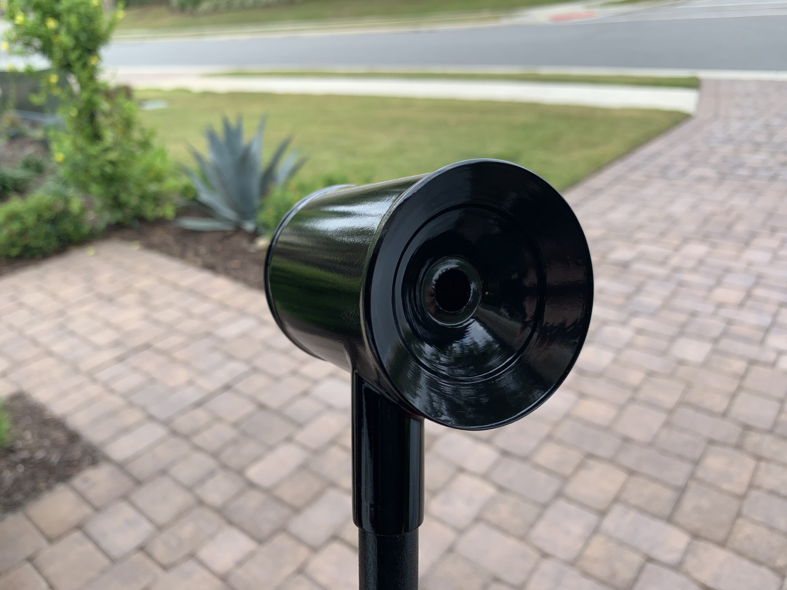
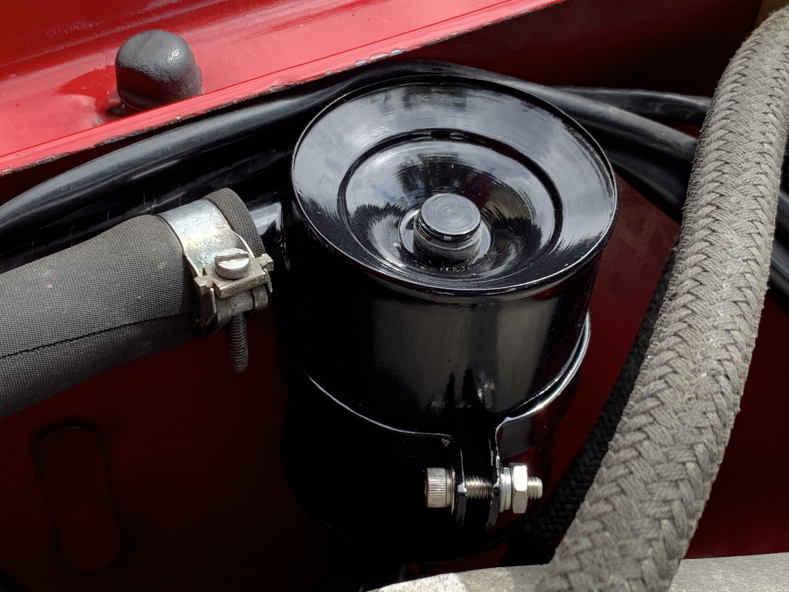
A NEW AND HOME MADE OIL VAPOR SEPARATOR
The Oil Vapor Separator (OVS) found on the Alfa was, I am sure, never designed to last thirty plus years. When dissected, one finds nothing but sludge and rust. New units are unobtanium, so one of the enterprising contributors to the Alfa Spider Bulletin Board designed and fabricated a kit made of brass to do the job of the original OVS. The down side of the kit is that it must be assembled requiring some artful soldering, but with a little practice the requirement is not too daunting. I put together a separate post on the OVS kit found at this link: https://valvechatter.com/?p=12619
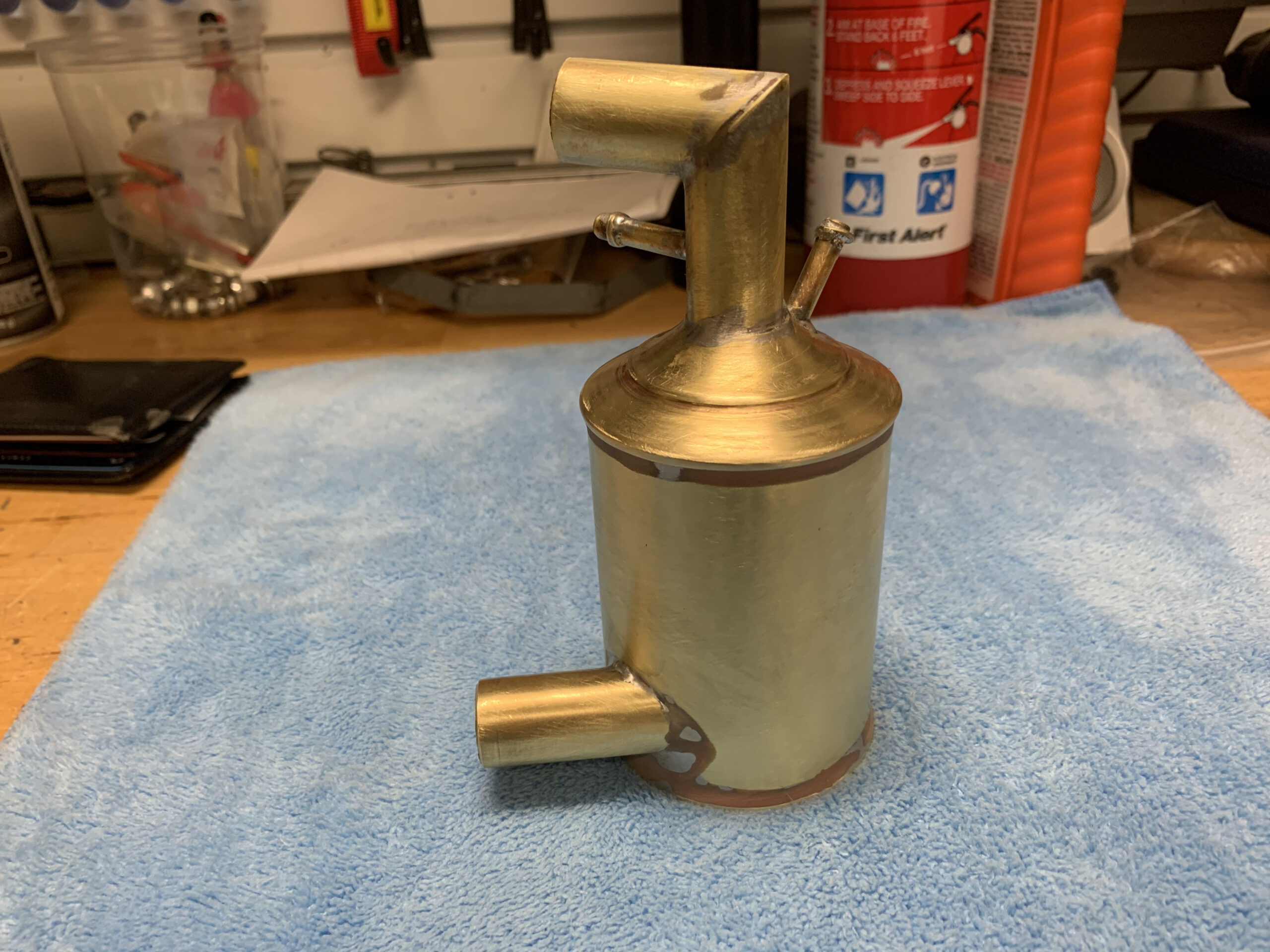
There are more photos in the OVS post, but here are a few of the assembled kit:

OVS Painted

OVS Installed
February 15, 2021
70,747 miles on the odometer
HANDBRAKE ADJUSTMENT AND PARTS, DOOR BUFFERS, AND POWER MIRROR SWITCH
In the last ten days or so I have tracked some of the low hanging fruit to fix on Alfie, I have continued my cleaning – but this time under the car, and I decided to trace the fuel system and vacuum hoses to inventory the types and sizes of hose clamps used on the car. Most of the original hose clamps are still on the car but a number have been replaced and usually with cheap inappropriate clamps. The clamp inventory project turned out to require a bigger effort and time commitment than I thought. I will make this the subject of a separate category and post at this location: https://valvechatter.com/?cat=2043.
I ordered an upper radiator hose and installed it only to discover that the radiator leak must be from the top of the tank rather than from a perished old hose! This will require some further attention, but it looks like either a radiator repair or replacement is in my future.
The handbrake did not function at all so I undertook a fault finding mission and the restoration of braking. As it turned out, the handbrake mechanism located at the rear of the differential was rusted in place and frozen preventing the operation of the brakes.
This is a photo of the original cable mechanism. As the center cable is pulled (at the top in the image) when the handbrake arm is lifted, the two brackets with the LH and RH cables (in the middle of the swivel arms) are supposed to pivot and pull the drum brake cables tight. However, mine was rusted and frozen in place and consequently did not operate properly.
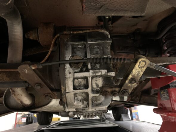
Handbrake Center Cable Mechanism Mounted
I ordered a new mechanism from Centerline International and installed it on the car. The original part number is 605.17074 with Centerline’s order number being BC420. The item was $59.50.
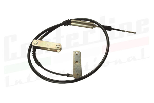
Alfa Center Brake Cable
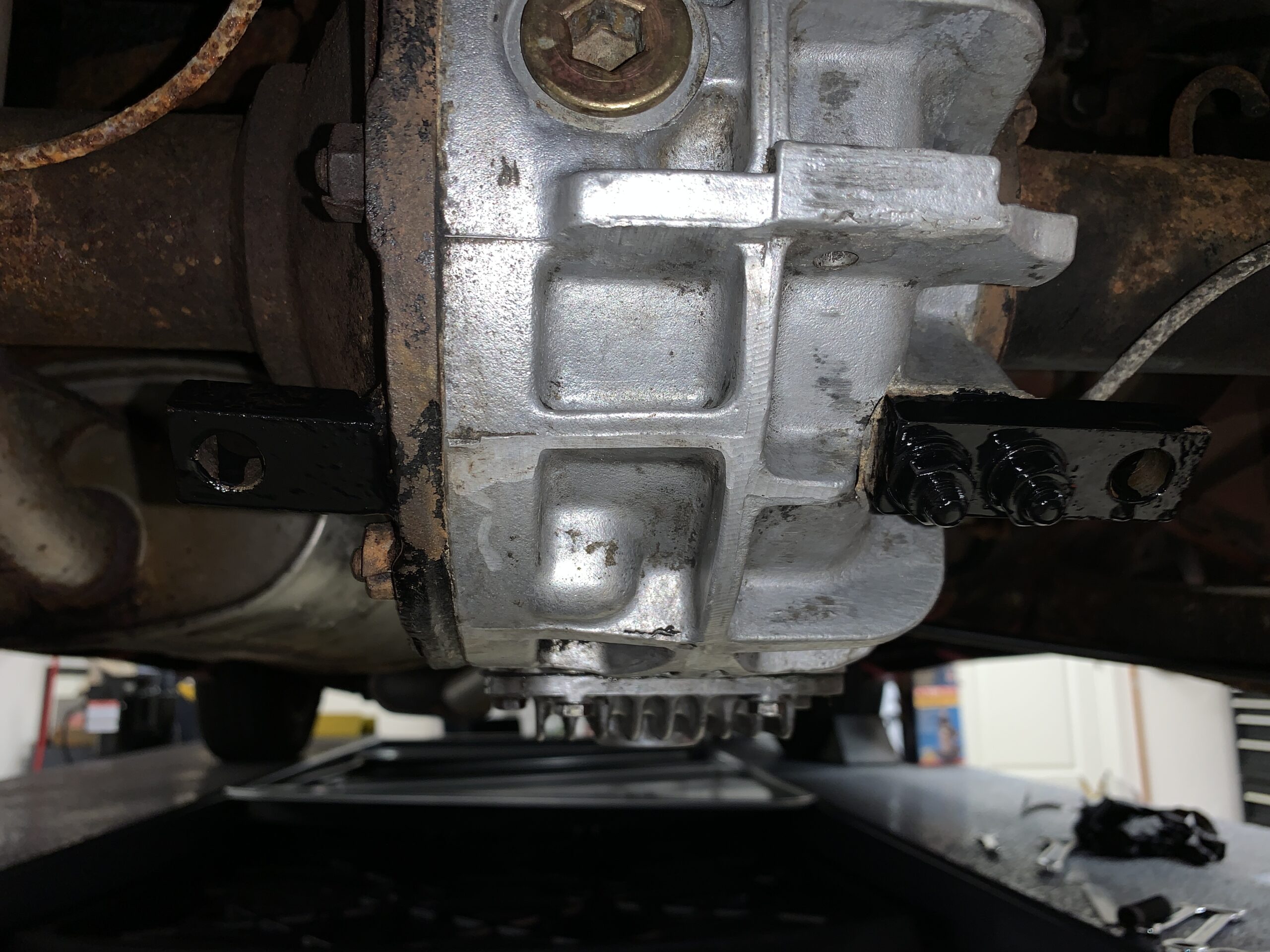
After removing the old assembly, I took the opportunity to clean up the differential a bit more and I painted the two steel mounting blocks just to prevent them from further rusting.
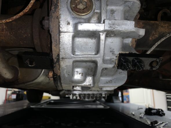
Handbrake Assembly Mounts
I then installed the new assembly. I applied synthetic grease to the rotating components. Yes, that really nasty looking brake pipe is one of the next few items that will get my attention!
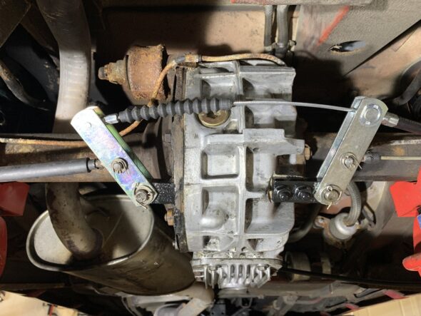
Handbrake Assembly Installed
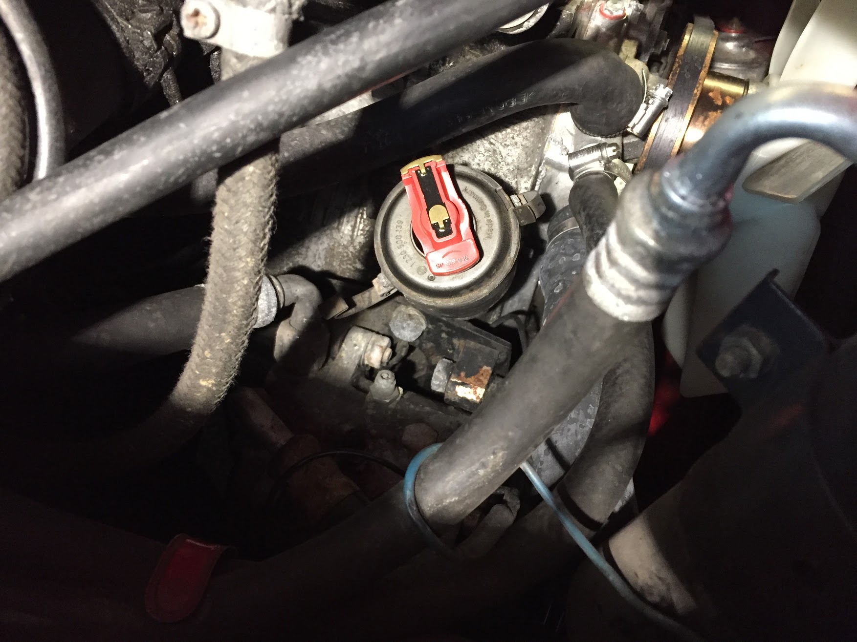
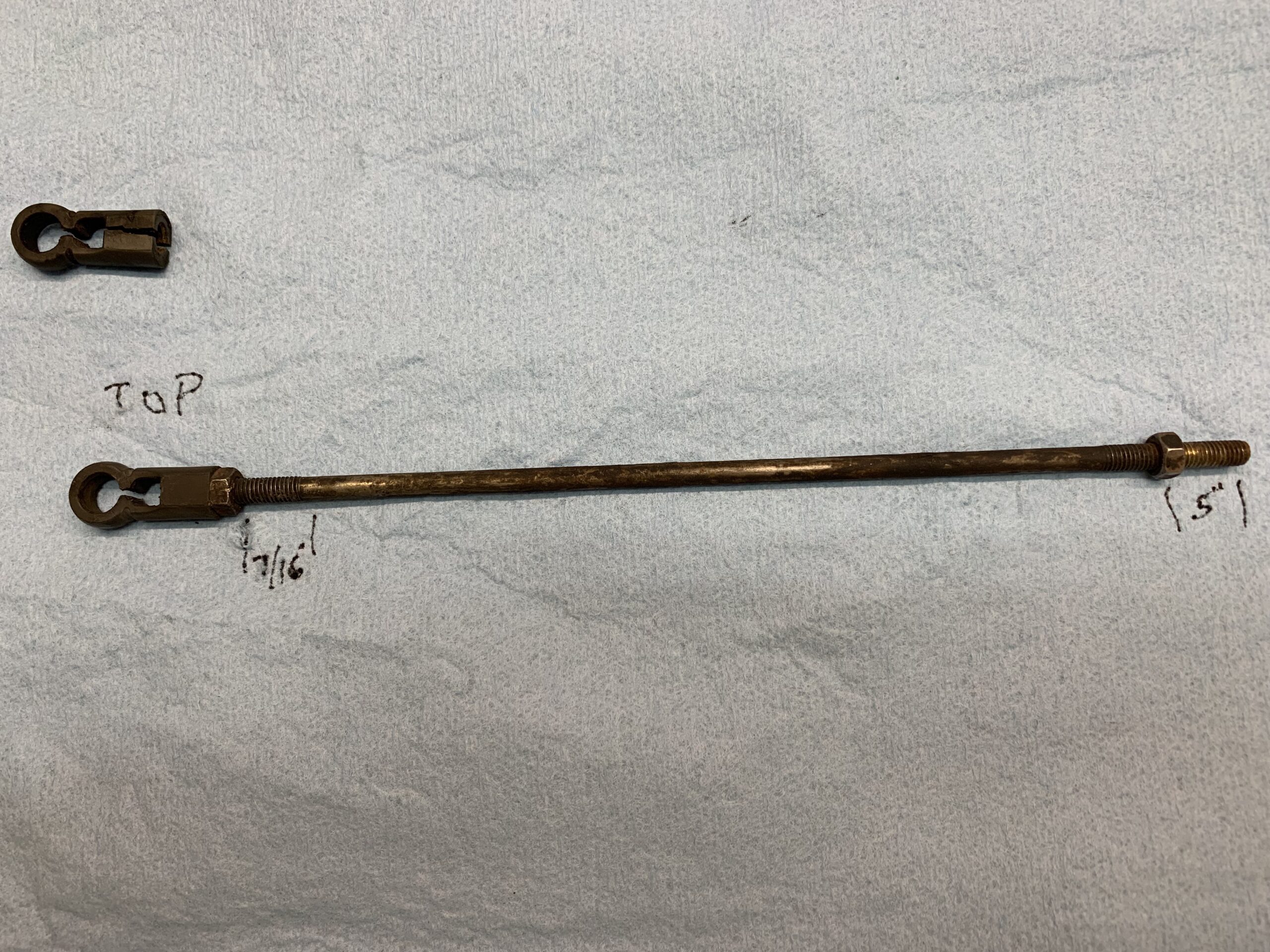
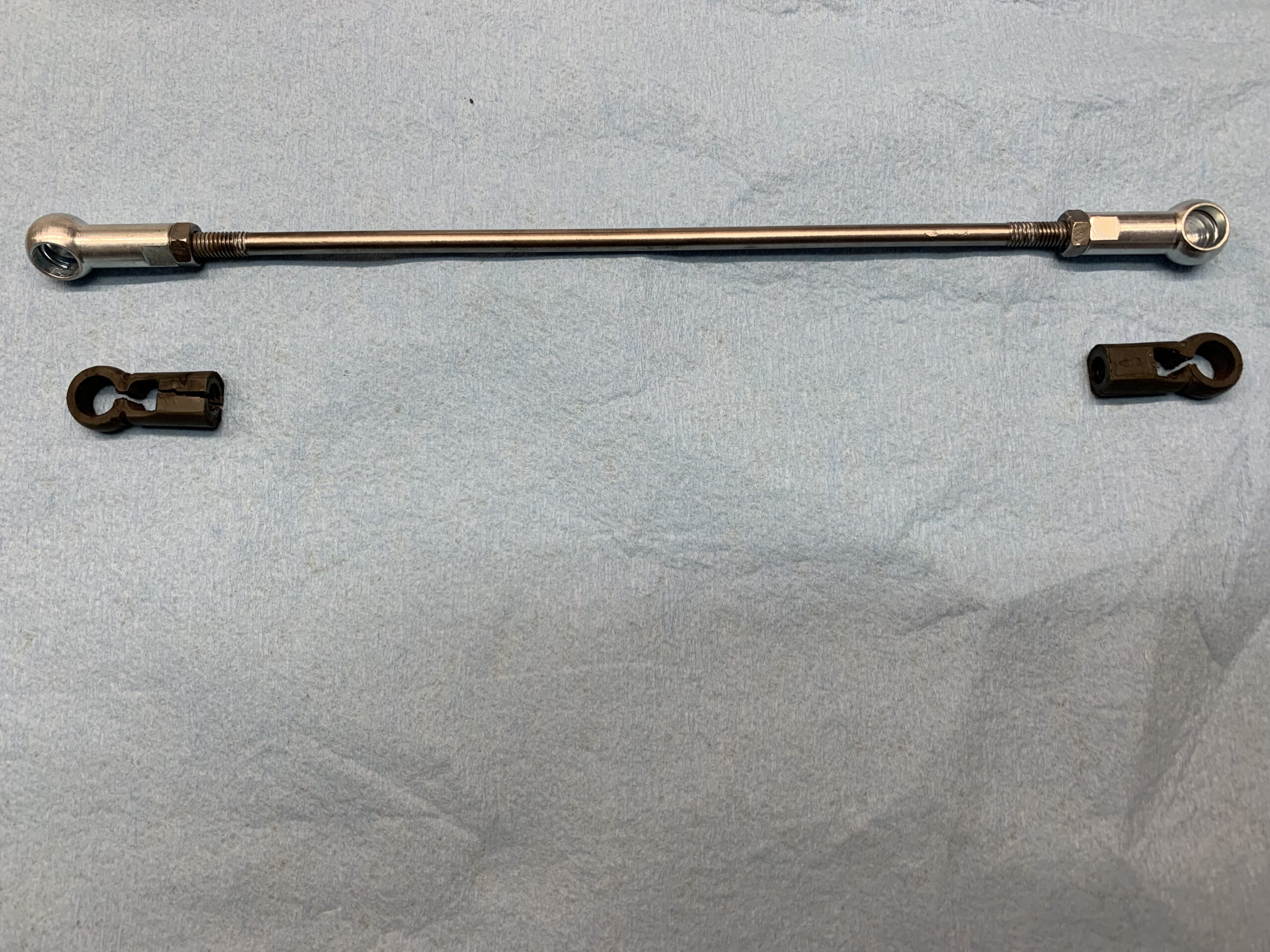
At the other end of the cable I attached a new fork to the handbrake lever with a cleaned-up clevis pin and new split pin. The cable slides through a threaded fixture on the car chassis. It is the red item in the photo below. The cylindrical device is a rotary adjuster that is used to tighten/loosen the slack in the primary center cable.
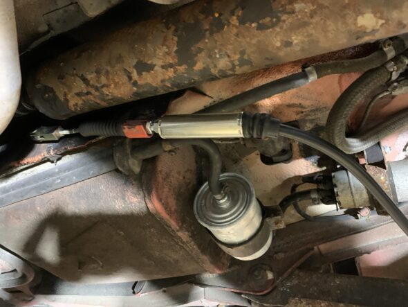
brake cable adjuster
The first step in actually adjusting the handbrake is to place something heavy on the handbrake handle to keep it down (depressed) while making alterations to the system. I then lifted the rear of the car so as to remove both rear wheels/tires. This makes the rear brake rotors accessible. The handbrake works by expanding two small brake shoes inside the drum (rotor). There is a star adjustment wheel inside the drum that expands and contracts the shoes against the drum surface. Using a screwdriver the star adjuster can be moved toward the front of the car (loosen/contract) or toward the rear of the car (tighten/expand).
After removing the disc brake caliper one can loosen and remove two screws and then pull away the rotor/drum – AFTER CONTRACTING THE SHOES. However, in my case it was not necessary to remove the caliper and rotor drum. Because the handbrake is almost exclusively used when the car is stationary, the shoes actually have very little wear.
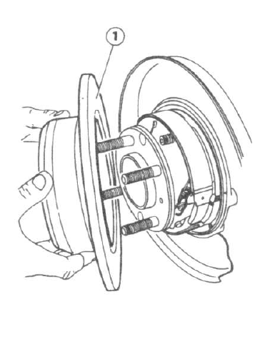
Rear Brake Rotor & Handbrake Drum
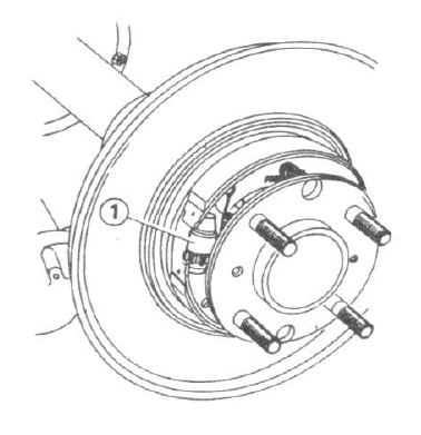
Brake Shoe Adjustment Wheel

Turning the Adjustment Wheel
I then turned the adjustment wheel on both the LH and RH wheels to fully tighten the shoes against the drum. I then loosened each adjustment wheel three clicks. This enables the wheels to turn freely or perhaps with just a slight friction or rub. Once this is accomplished, the next step is to turn the cylindrical cable adjuster to tighten (not overly) the center pull cable for the brakes. This process resulted in my handbrake working fully on the third click on the brake pawl.
I then reinstalled both rear wheels/tires and torques the lug nuts to 70 ft. lbs. I then tested the handbrake in the driveway and again after a short test drive and concluded that one more task could be checked off the list!
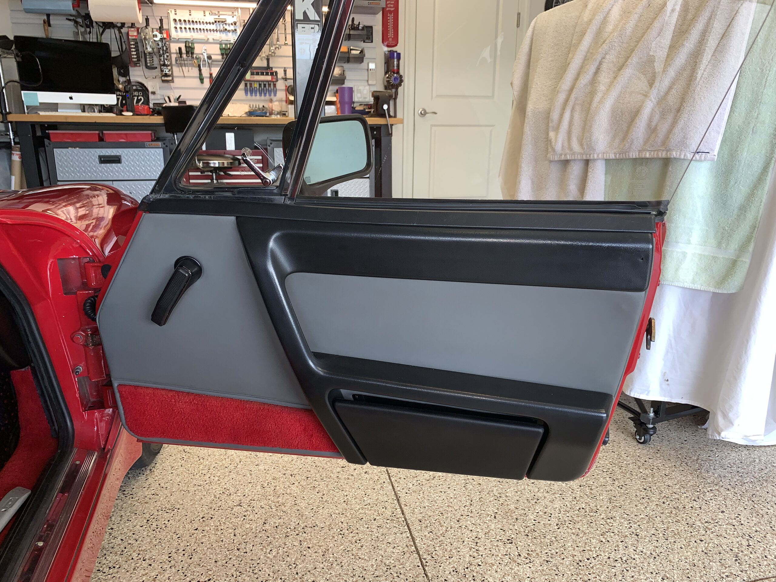
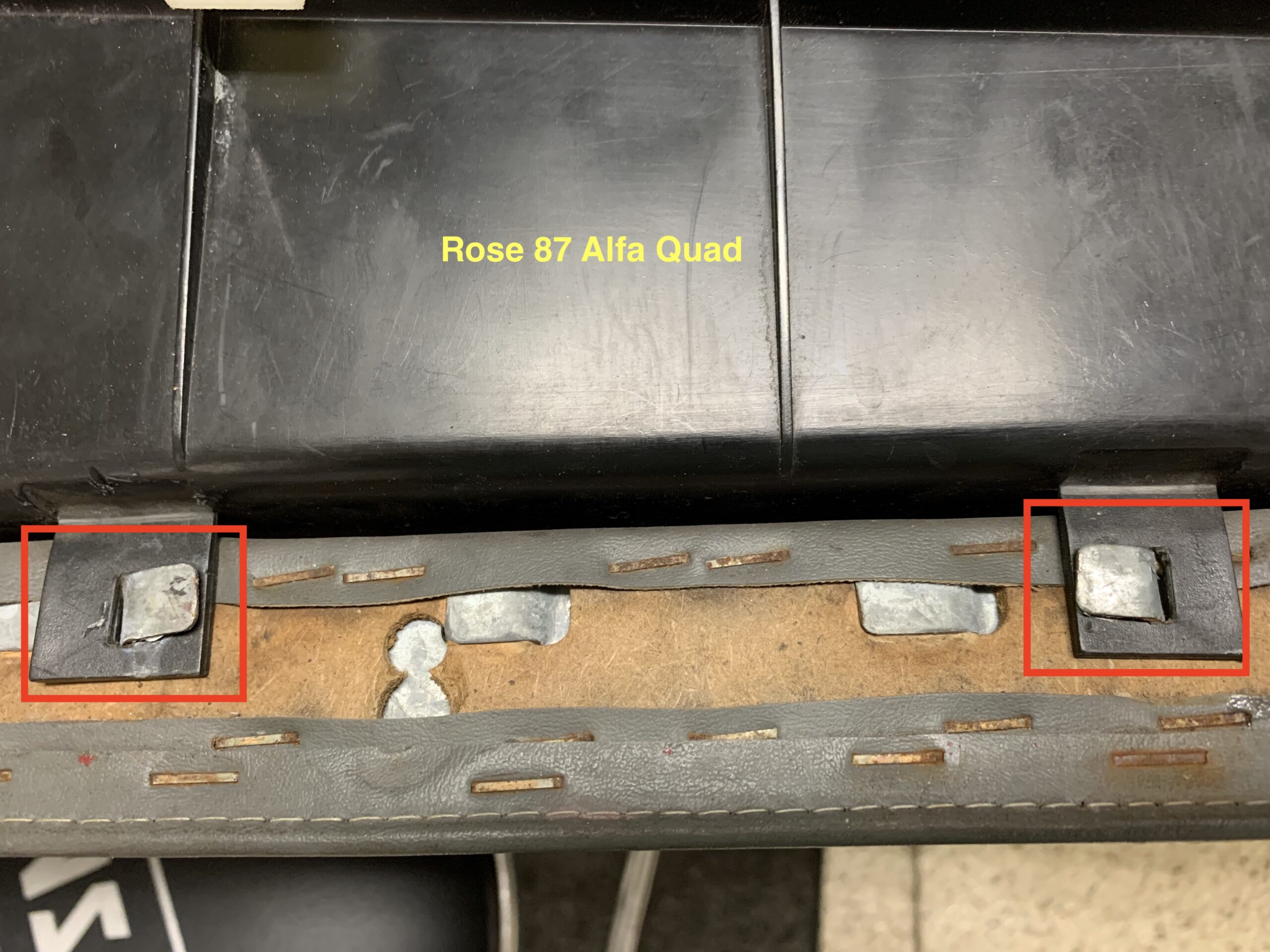
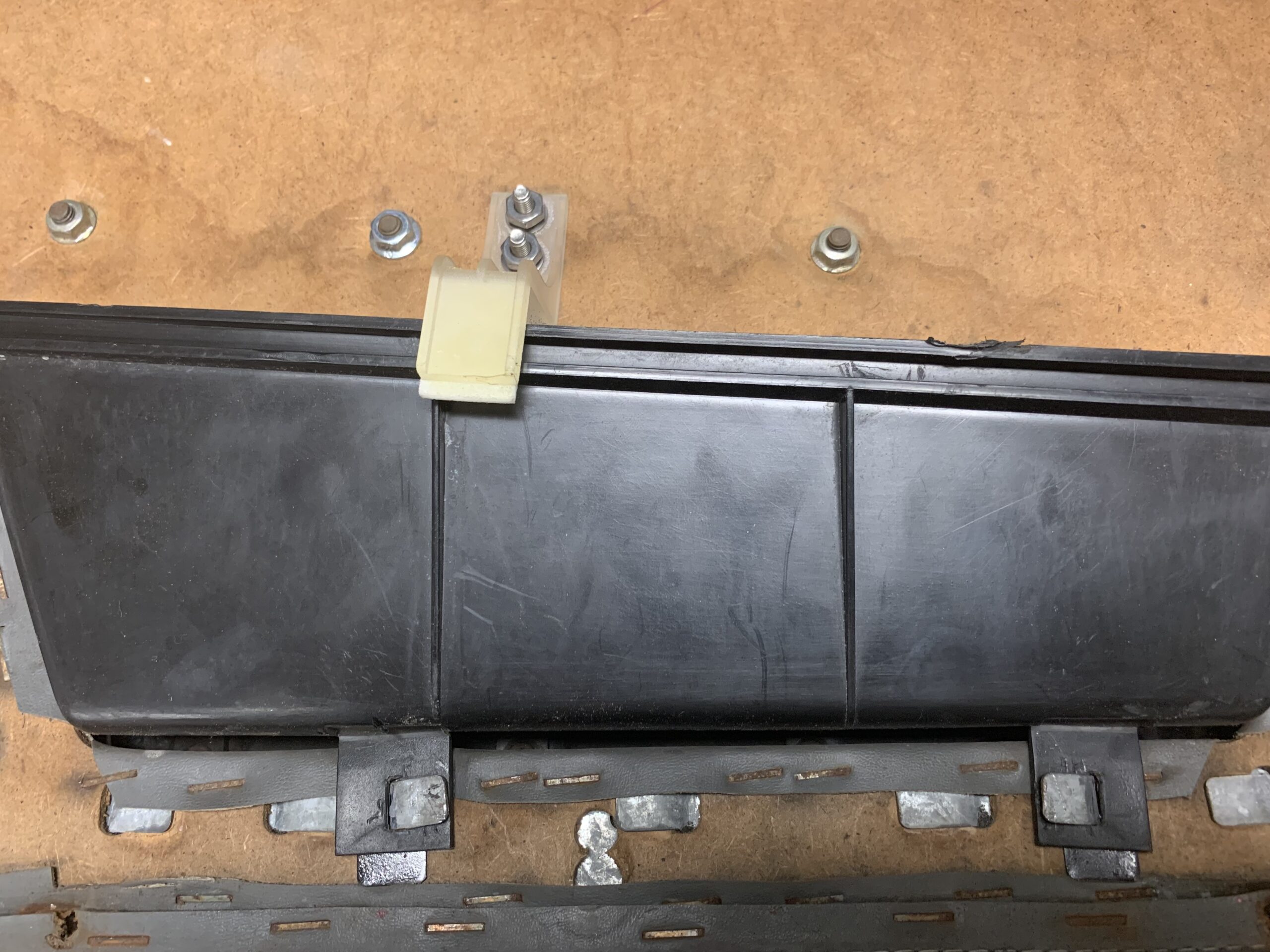
The rubber door buffer on the RH door was broken and deteriorating. I ordered a replacement from Classic Alfa part number RB061 for $7.10 and installed it by removing two Phillips head screws from a threaded captured plate pin the rear of the door.
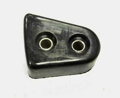
Rubber door buffer
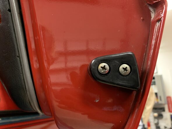
Rubber Door Buffer Installed
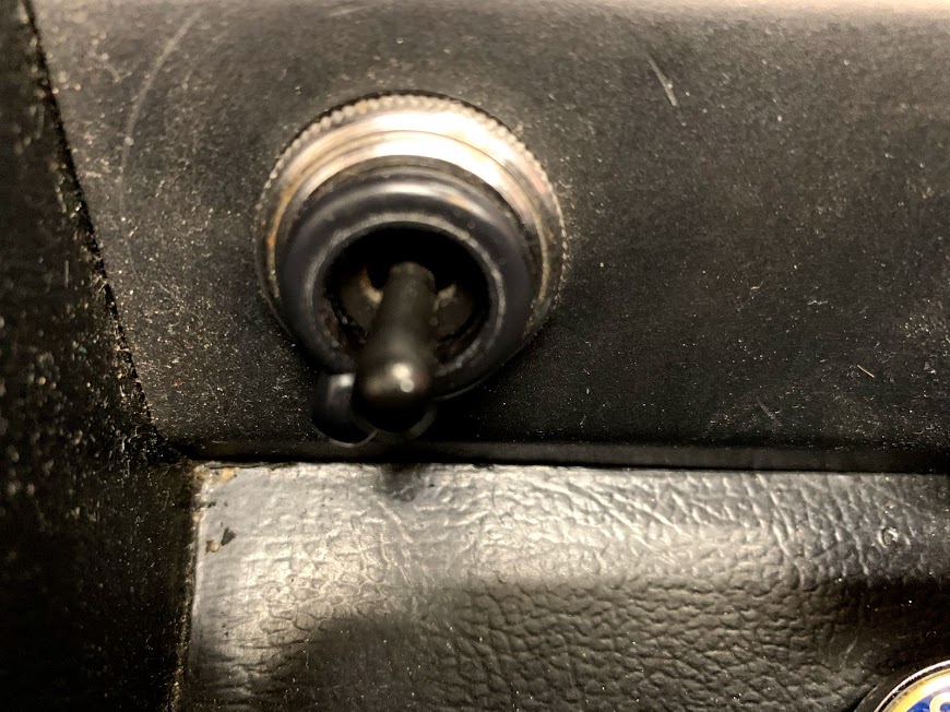
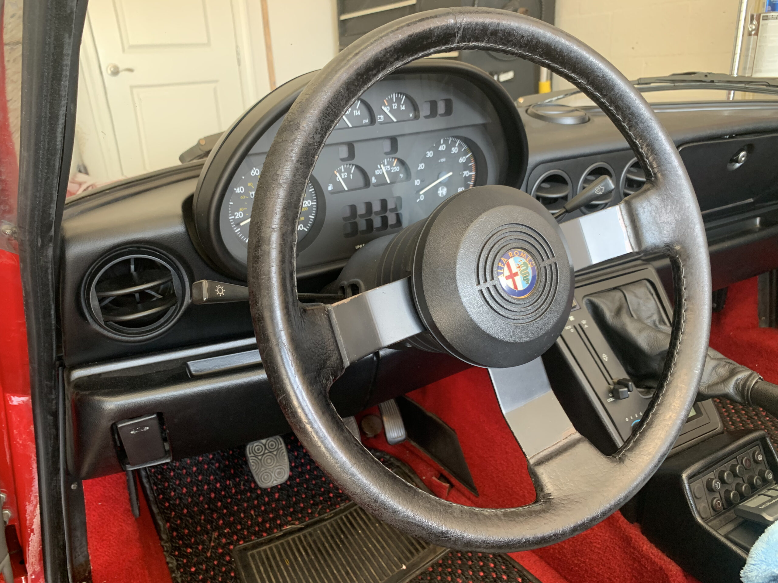
The Alfa has power mirrors on each door. They are controlled by a small switch with a rotational stalk on the center console and each mirror is selected by turning a ring with a selector tab to one side or the other. Alfie was missing the selector ring but I was able to find one (and a spare) from a fellow Alfa owner who frequents the Alfa Bulletin Board. The little ring must be carefully positioned on the switch and then pressed into place. Once installed Alfie’s mirrors both functioned properly!
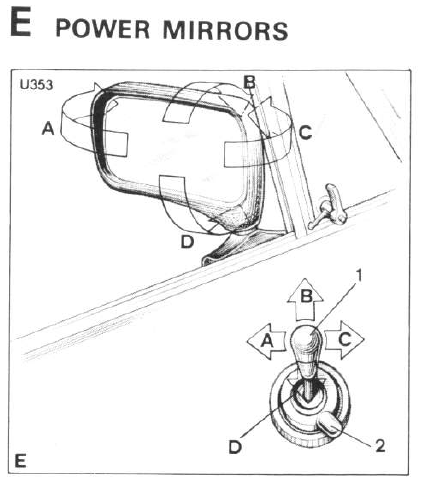
Power mirror control
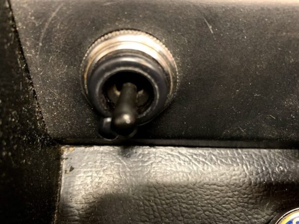
Power Mirror Switch
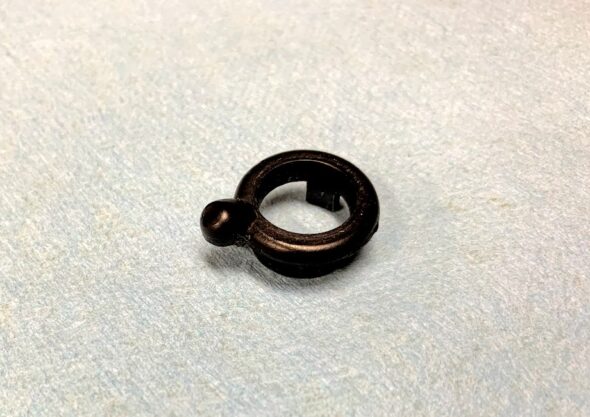
Power Mirror Selector Ring
January 31, 2021
70,735 miles on the odometer
ALFIE RELOCATION AND PROJECTS LIST
After a longer than expected storage at the Madison Automotive Apprentices Shop in Harrisonburg, VA I finally transported Alfie to our home in Florida. We don’t really have the space for him, but we will make do. I need a project, Alfie needs some work and the time is right!
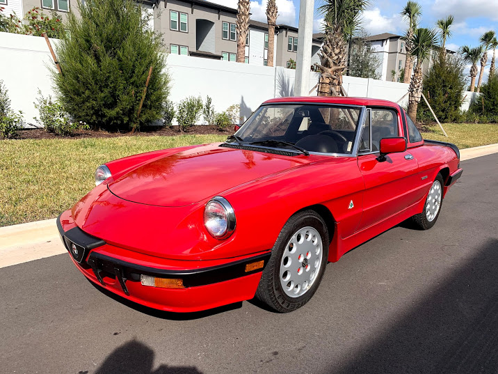
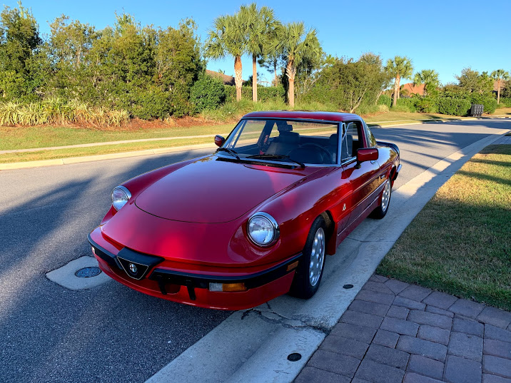
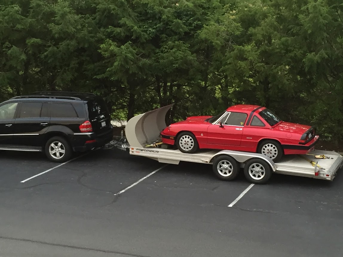
Passport Transport (Camille) moved the car to Florida. The process took about four days. here is a shot of the car being unloaded in Bradenton.
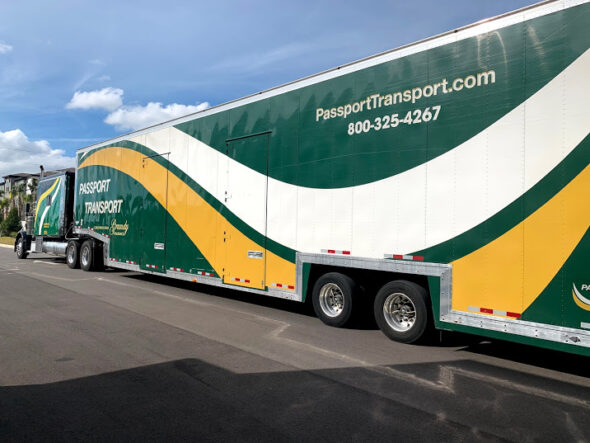
Passport Transport Delivering Alfie to Florida

Alfie Unloaded in Bradenton
While he looked good in the Florida sunshine, he was actually quite dirty. He started just fine. The brakes felt a little squishy, but I drove Alfie the 2-3 miles home from the delivery point.
The first thing I did was wash, polish (with a buffer) and wax the car just so it had some protection and, of course, he looks a lot better too. I then began a process of inspection and discovery to see what worked properly and what did not. I began with the interior and exterior while the car was on the ground and then followed that with putting it on the garage lift to clean and inspect the underside. I took literally hundreds of photos and made a few videos of the entire car. I can use these to compare my car to others and to answer my own questions about how things were BEFORE I started tearing things apart. My experience with this is that you can never have enough photos. More is always better.

After Wash and Wax
I was pleased, and surprised to find that most things electrical worked as they should. A few needed some cleaning and coaxing such as the courtesy lamps. I have spent a lot of time on the Alfa Romeo Bulletin Board and learned a great deal. One of the contributors suggested that I should snap the door jamb switches a few times and spray them with some electronics contact cleaner. I did just that, and like magic the courtesy lights are now working!
I am sure that I will discover many other items that need attention. Should be fun! I will begin a separate category and post for “To-Do” List items and check them off as I am able to accomplish them.
July 10, 2017
70,600 miles on the Odometer
IGNITION REFRESH
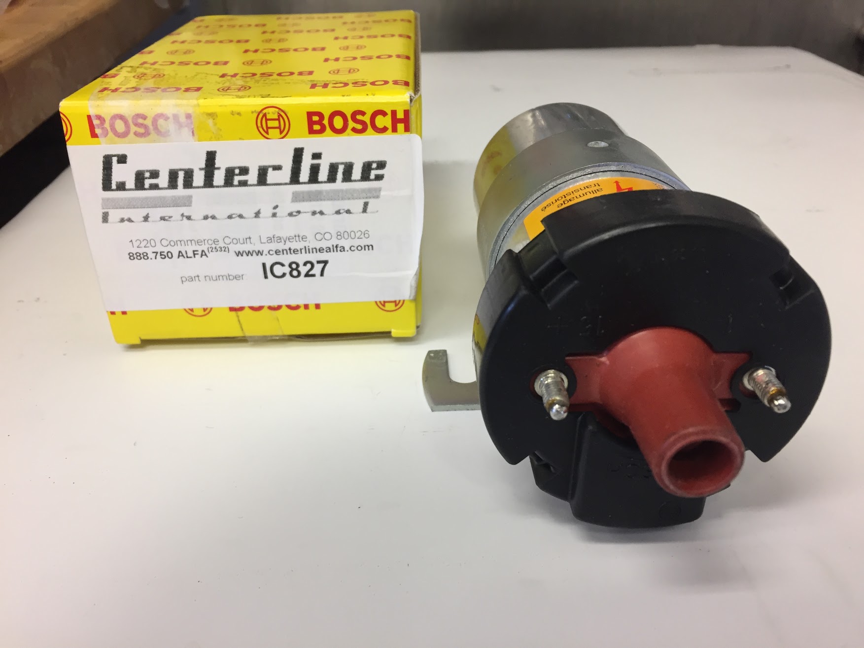
I am experiencing some starting problems that seem to be due to a partial discharge of the battery after the car has been sitting. Not knowing the car and what others may have changed/updated/disconnected or connected, I thought I would begin by replacing components in the ignition system including the distributor cap, ignition wires, rotor and coil. I ordered these components from Centerline International.https://www.centerlinealfa.com/store
Centerline International Invoice
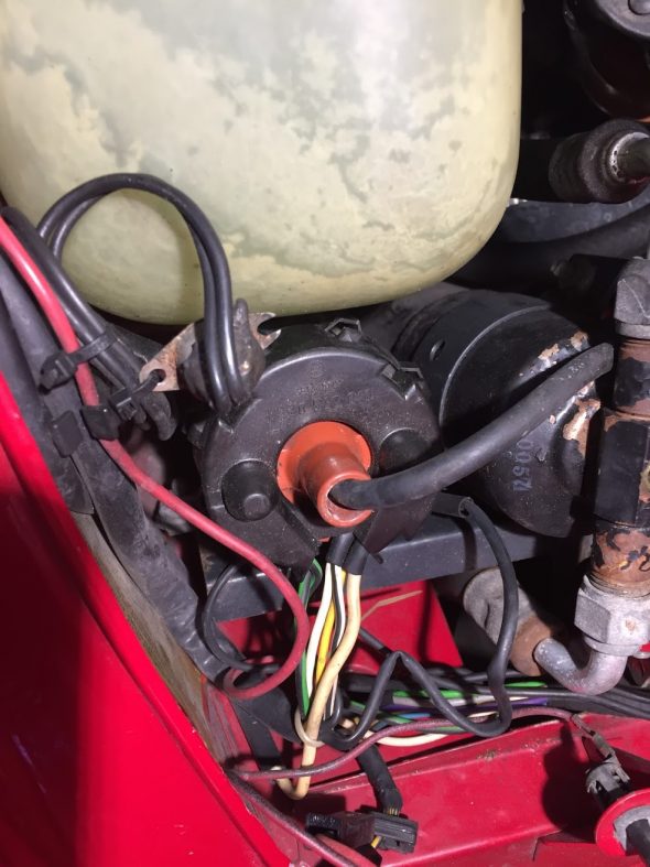
Old Coil to be Replaced

New Bosch Coil to be Installed
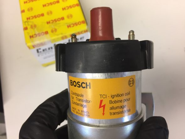
New Bosch Coil to be Installed
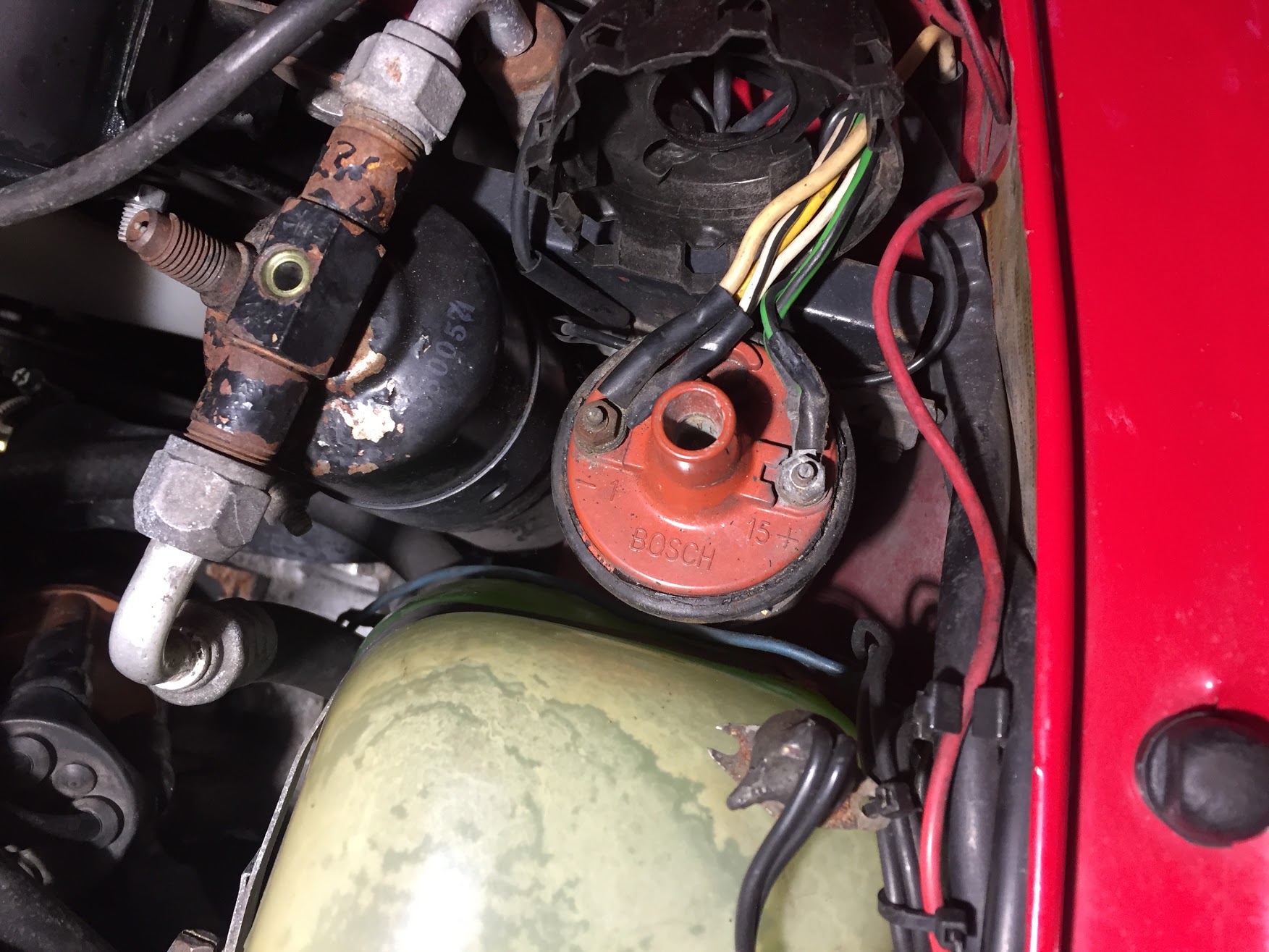
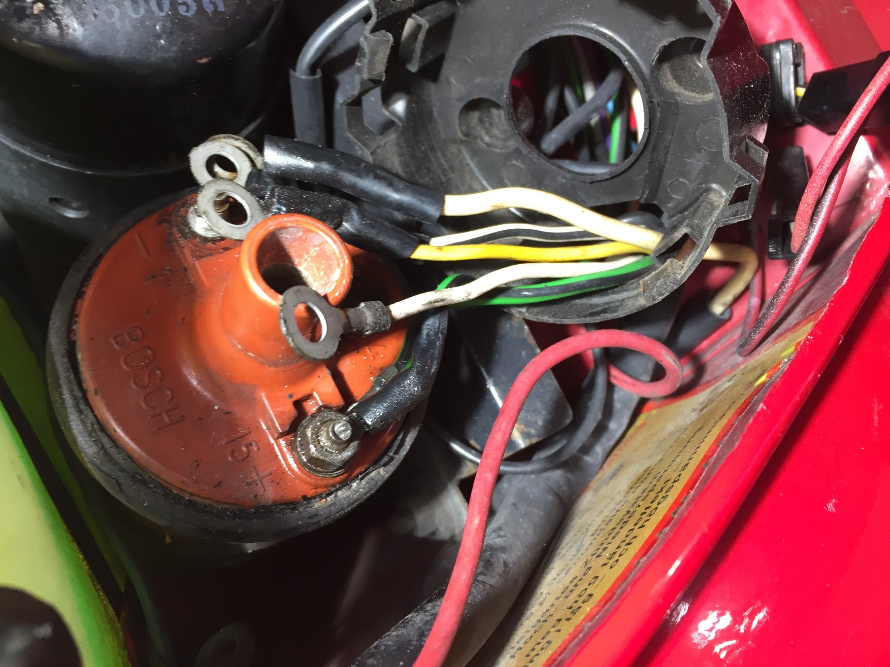
I began the task by removing the old coil. There are a total of six wires connected to the coil terminals. The (-) terminal has four wires secured to the mounting post with an 8mm nut: a larger cream-colored wire, a white wire with a black tracer, a yellow wire, and a white wire. The (+) terminal has two wires and both of them are light green with black tracers.
Wiring to the Old Coil

Wiring to the Old Coil
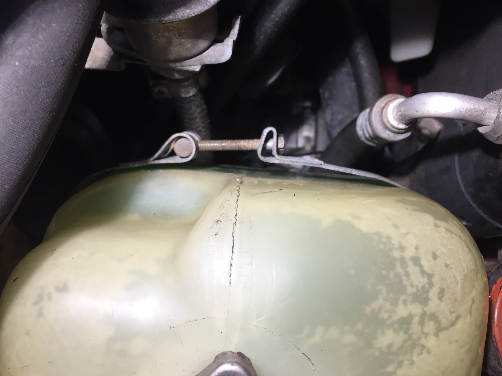
To access the mounting bracket nuts for the coil, I found it easier to first remove the coolant recovery tank. This was accomplished by loosening the screw in the bracket connection and then lifting the tank temporarily out of the way.

Coolant Overflow Tank Mounting Bracket
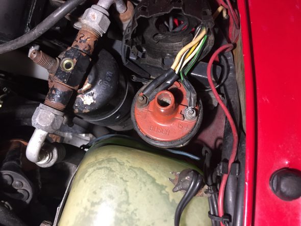
I was then able to remove the old coil and install the new one:
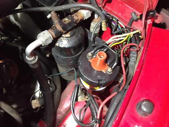
New Bosch Coil Installed
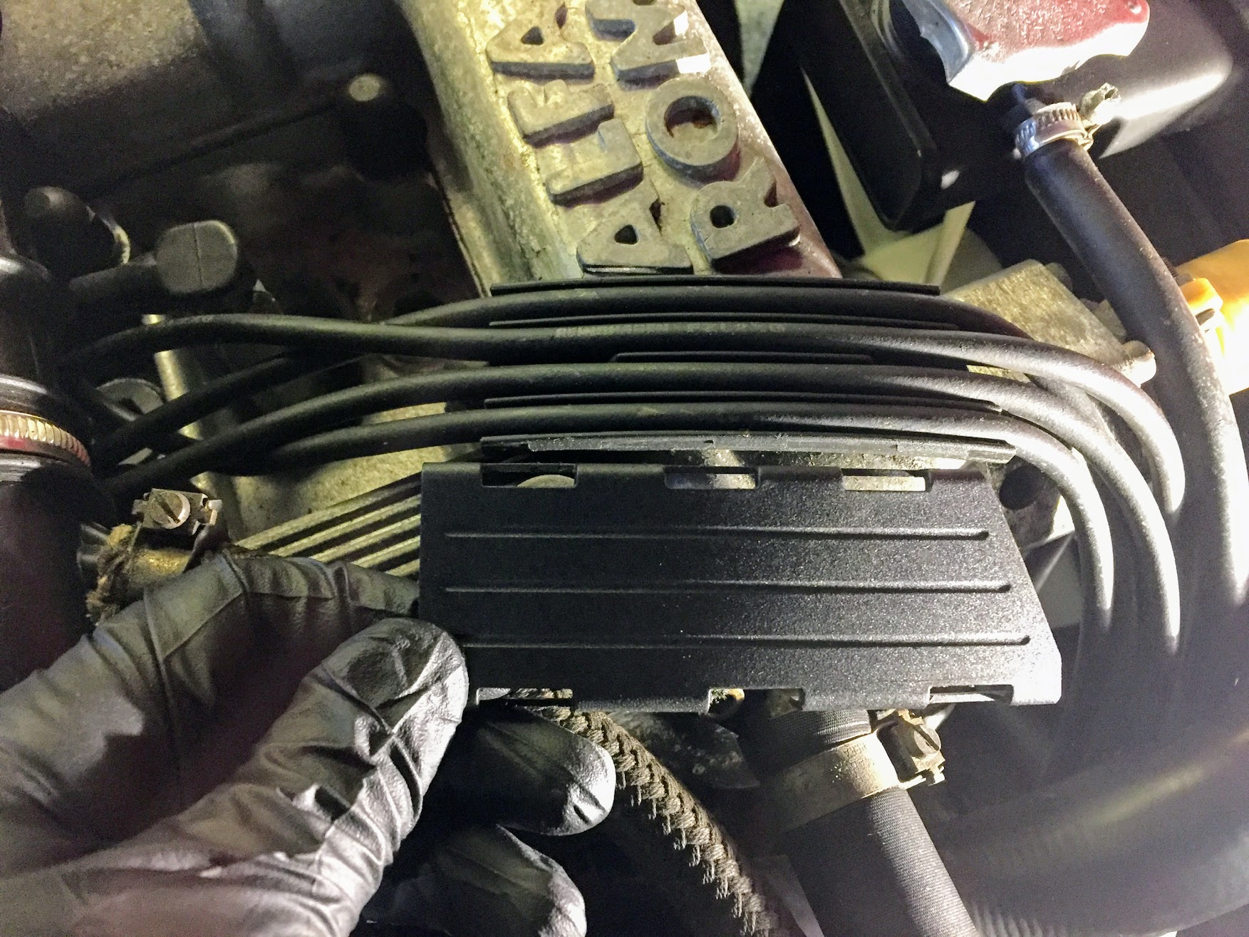
I then carefully marked each ignition wire with a number to designate its location for replacement, and after also marking the old distributor cap for location purposes, I snapped the top off of the black plastic loom to free the wires.

Ignition Wiring Loom Harness
I then disconnected each wire at the spark plugs and popped free the two securing clips on the distributor cap. I could then lift away the old cap and wiring. I had previously disconnected the coil wire while replacing the coil.
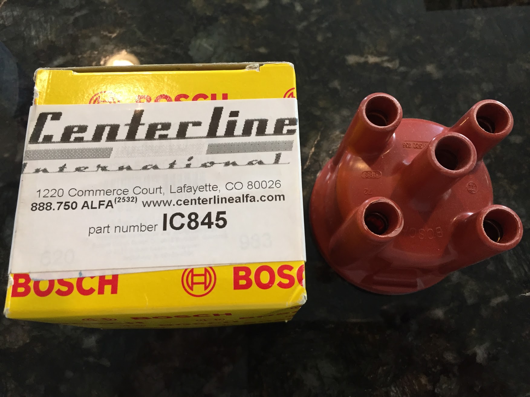
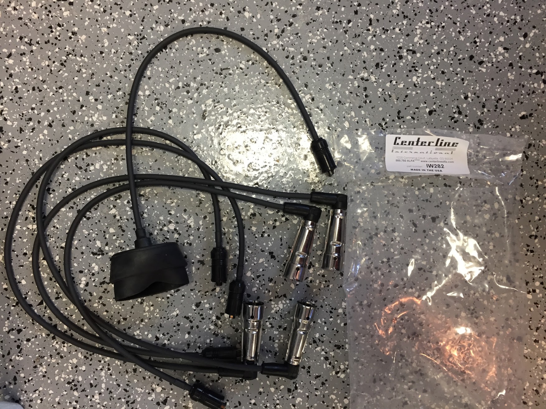
The new wiring came with numbers on each wire. After properly locating the wires in the appropriate place on the new distributor cap, I pushed the wires into their seats. This is a tight fit and they were somewhat difficult to fully seat. The coil wire included a rubber cap to press fit over the top of the coil.

New Bosch Distributor Cap
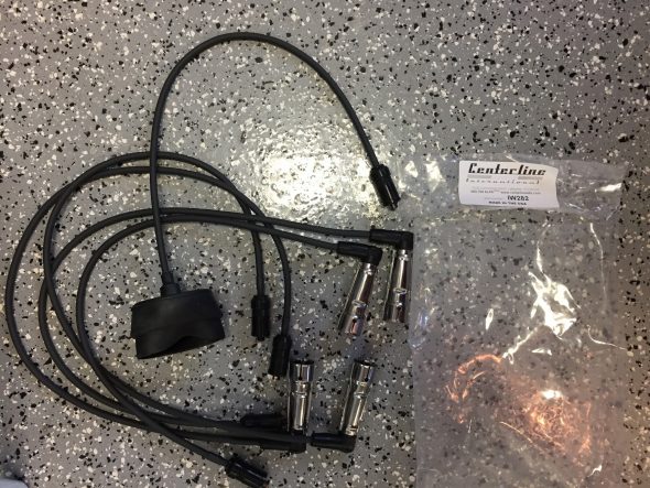
Alfa Spider Ignition Wiring Kit
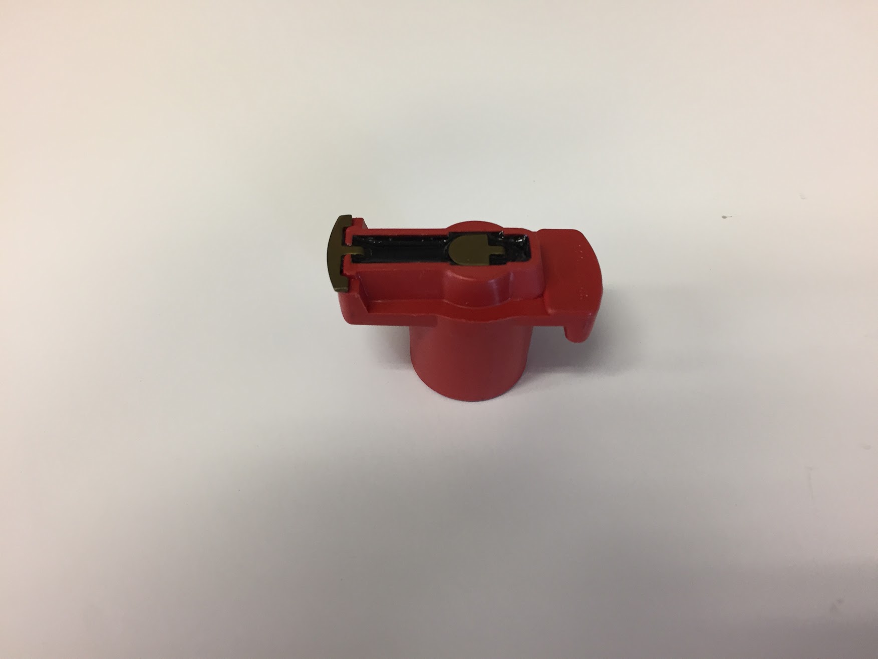
I then removed the old rotor and installed a new Bosch rotor on the distributor shaft.

New Bosch Rotor

New Bosch Rotor Installed
The new distributor cap and ignition wiring assembly was then reinstalled to the distributor and to each of the spark plugs and to the coil. The coolant recovery bracket was replaced, the coolant tank was restored to its mounted position and the bracket was screwed back together.
The task was then completed with a successful test drive.
However, I discovered the next morning that the battery discharge issue remains and I will now begin my sleuthing to try to discover the source of the problem.
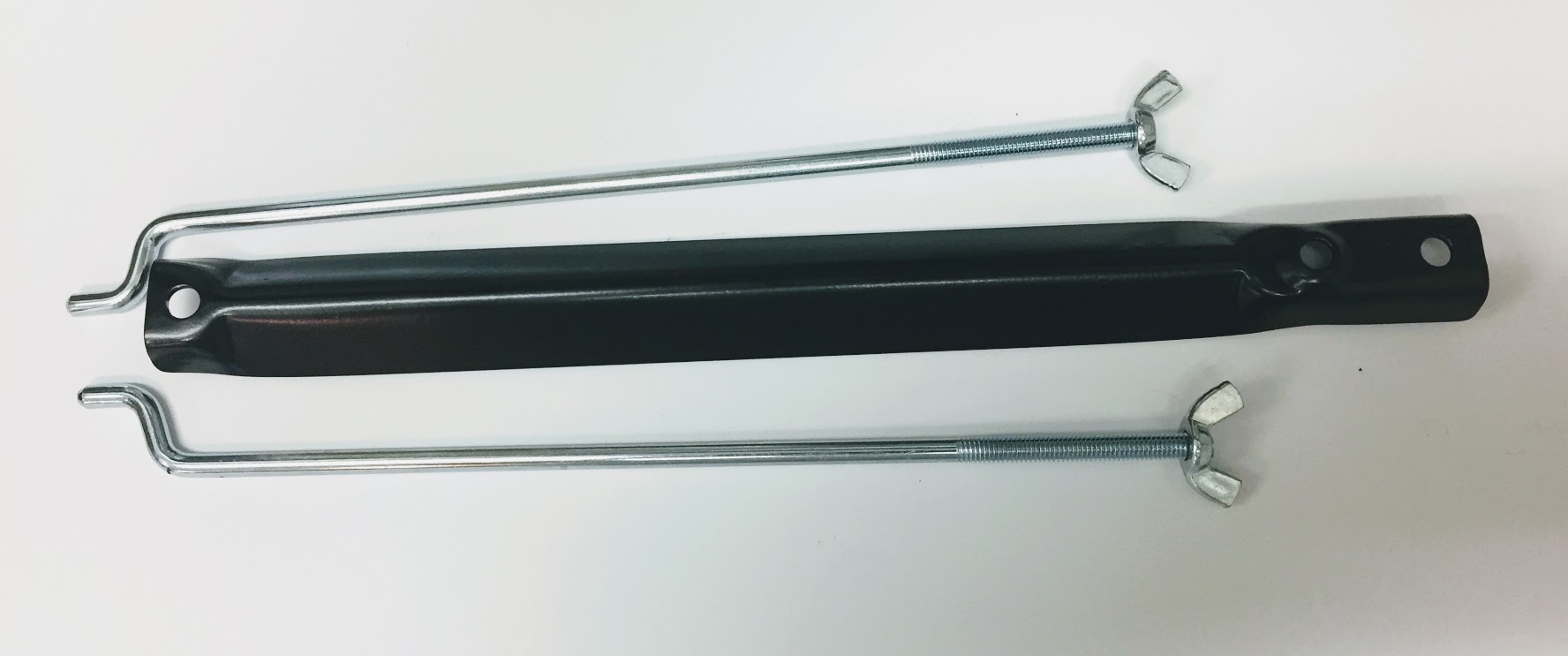
Battery Clamp Set
My battery bracket/clamp was pretty rusty and partially consumed by battery acid. I could have replaced it with a universal clamp for considerably less expense, but I chose to purchase and install the proper clamp set from Alfaholics in the UK. https://www.alfaholics.com/parts/105-series/electrical/battery-clamp-set/
Battery Clamp Invoice from Alfaholics
This is an image of the battery clamp set as it was received:

Alfa Battery Bracket
I just did not have the space at our home to keep Alfie and not having the time to work on him, I decided to relocate Alfie to a friend’s shop. After some sleuthing about, it was discovered that the start-up injector in the fuel injection system was not functioning properly and it was replaced. This solved the start-up mystery and the car now starts without any hesitation!