Exhaust System
Exhaust System Components
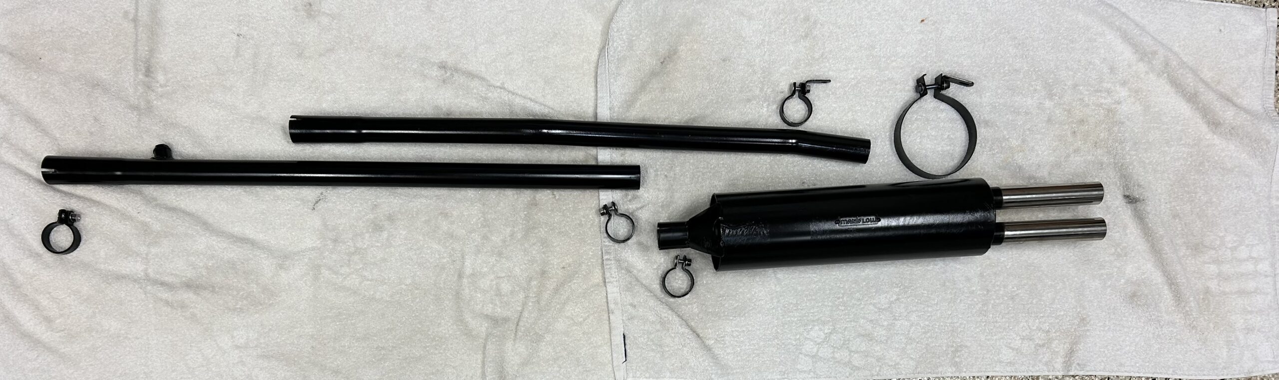
The primary components of the system include front and rear downpipes, a twin silencer assembly (one piece), and a twin tailpipe assembly (also one piece). Copper sealing rings are used to join together the downpipes and the exhaust manifolds. A series of clamps are used to secure the components to one another and two different systems of exhaust hangers are used to “hang” the exhaust system from the car.
Removal
The Jaguar Service Manual states:
“Remove the two nuts, bolts and plain washers securing the tail pipe under the rear bumper to the bracket of the body on the left hand side.
Slacken the two clips securing the exhaust down pipes to the silencers.
Remove the nut, bolt and washer securing the front of the silencers to the body.
Remove the two bolts, nuts and washers securing the middle of the silencers to the body.
Lower the tail pipes and withdraw the silencers from the down pipes.
Remove the four nuts and washers securing each downpipe to the exhaust manifolds on the engine, when the downpipes can be removed. Collect the sealing rings which are between the exhaust manifold and the downpipe.”
Refitting
Again, the Service Manual states:
“Renew the copper sealing rings when refitting the exhaust downpipes to the exhaust manifolds. Refitting is the reverse of the removal procedure.”
Of course, removal or reinstallation never seems to prove to be quite that easy!
Exhaust Hangers/Mounts
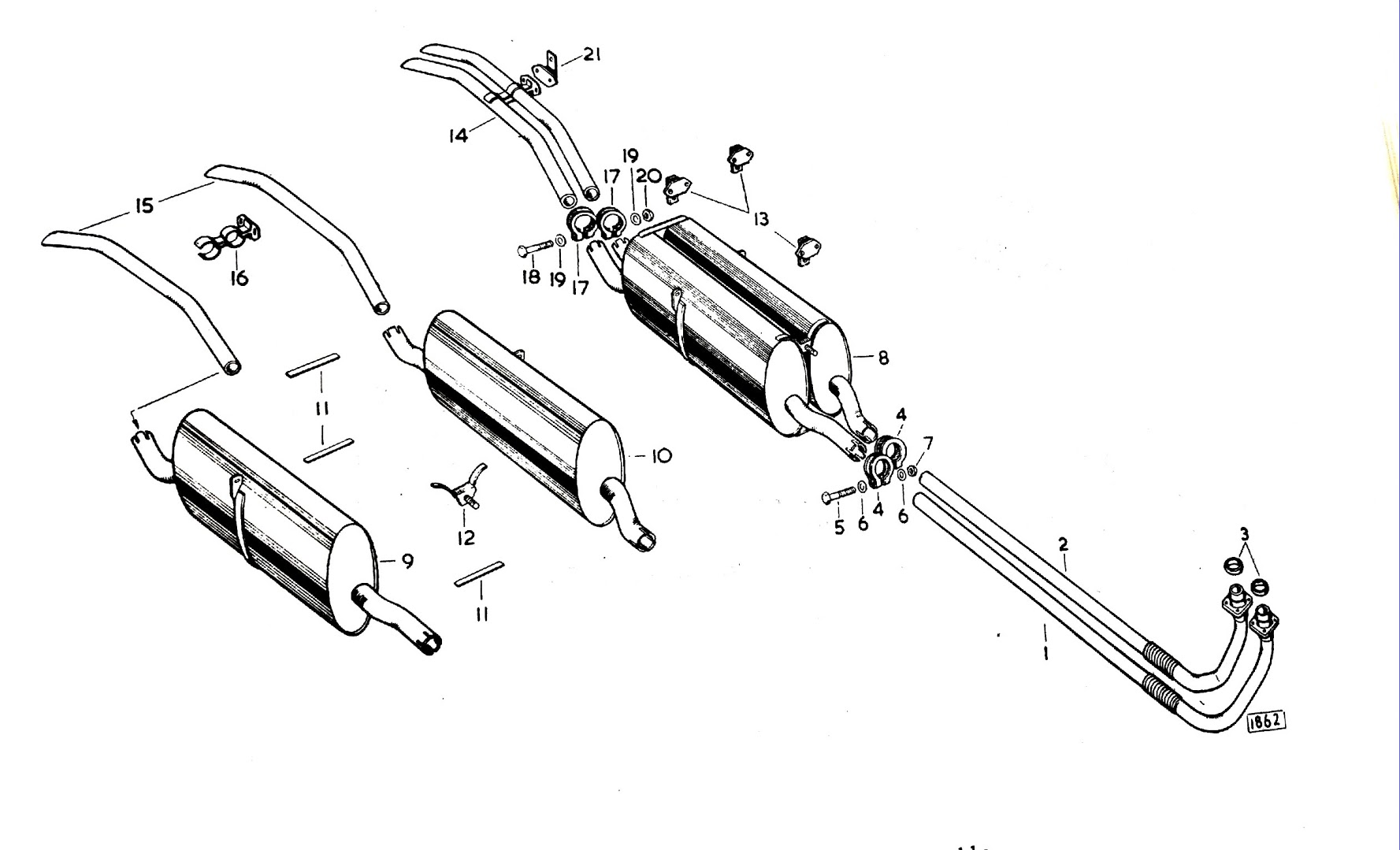
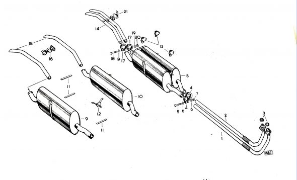
There is some confusion about the exhaust hangers (mounts) used on the MK2. Some cars use the hangers shown in the diagram above found in the Jaguar Parts Catalogue. This involves a “ring and pin” design with rubber bushings.
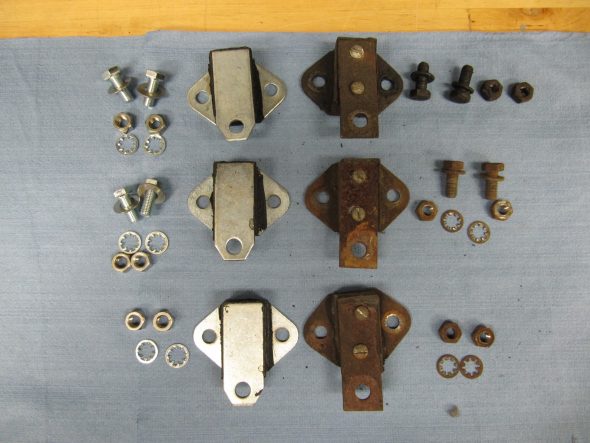
While others, including my car as it was disassembled, use rubber which is vulcanized to metal plates as the mounts. This arrangement is shown as the illustrative diagram provided in the Jaguar Service Manual:
Jaguar MK2 Exhaust
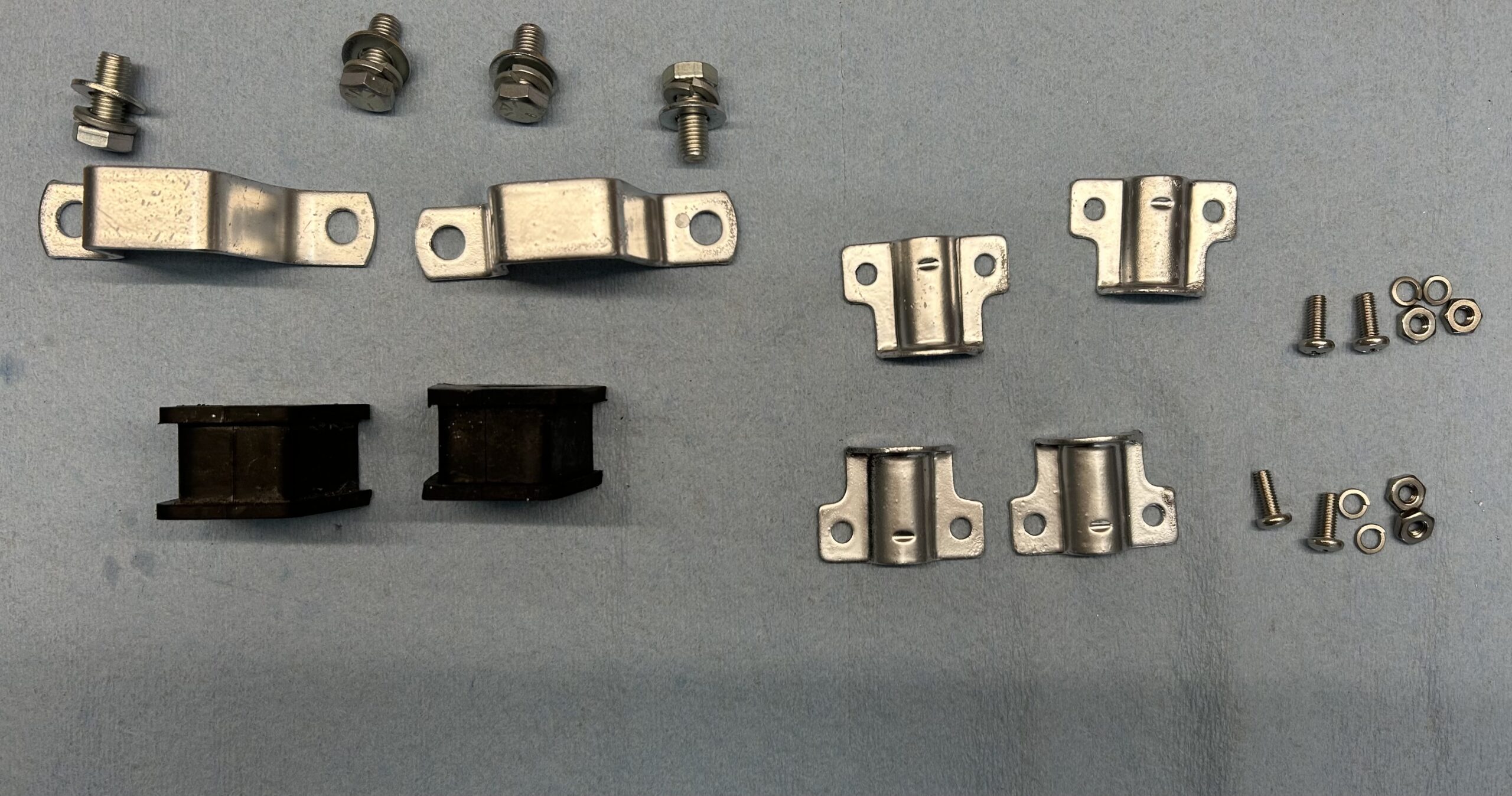
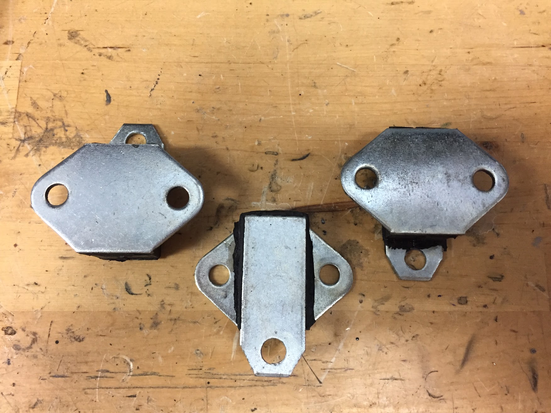
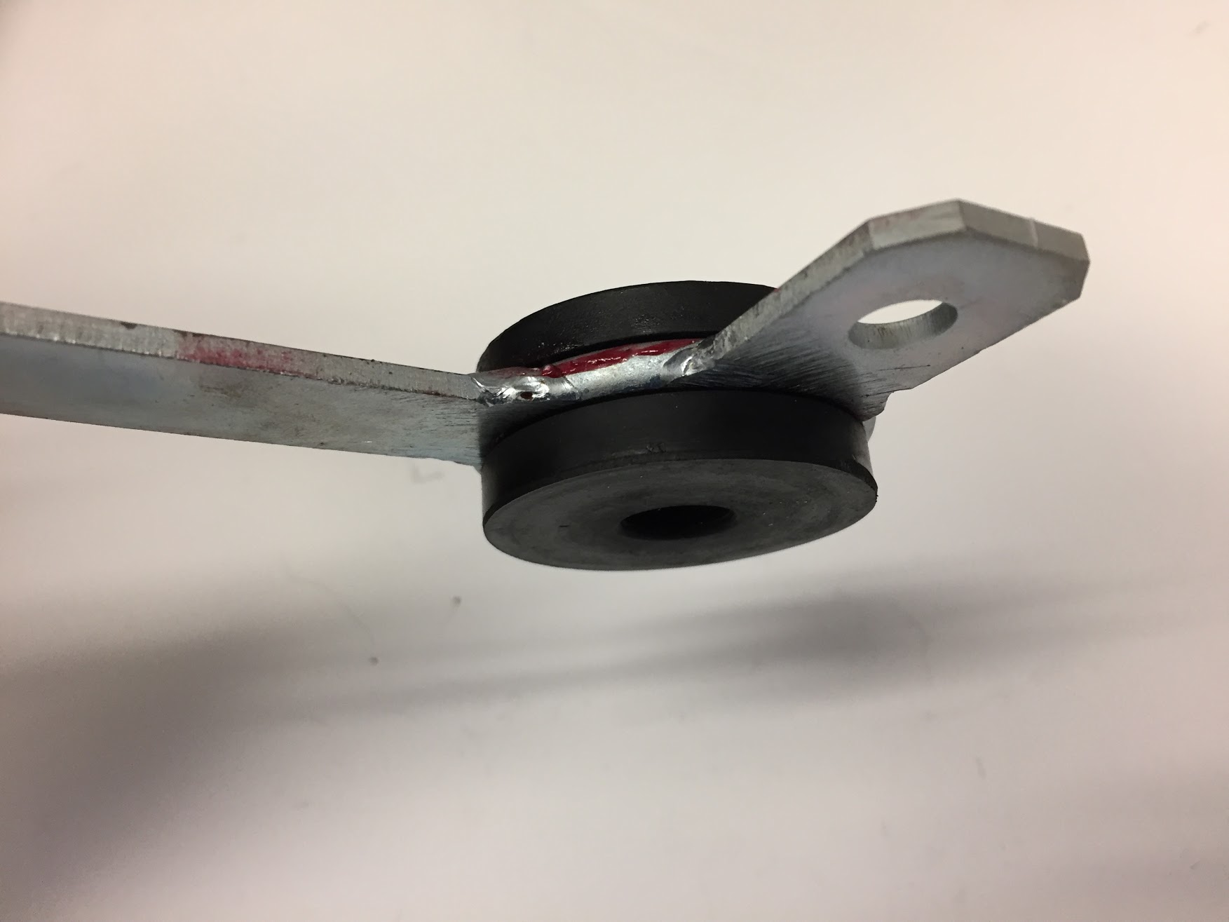
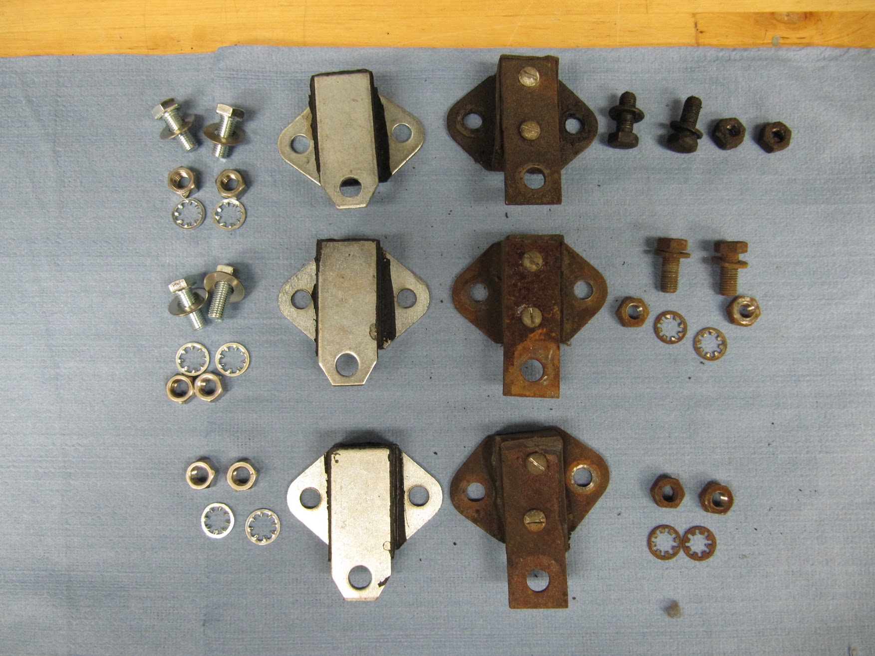
The bonded brackets are part#13 in the diagram immediately above and new mounts look like this:

Vulcanized Exhaust Brackets
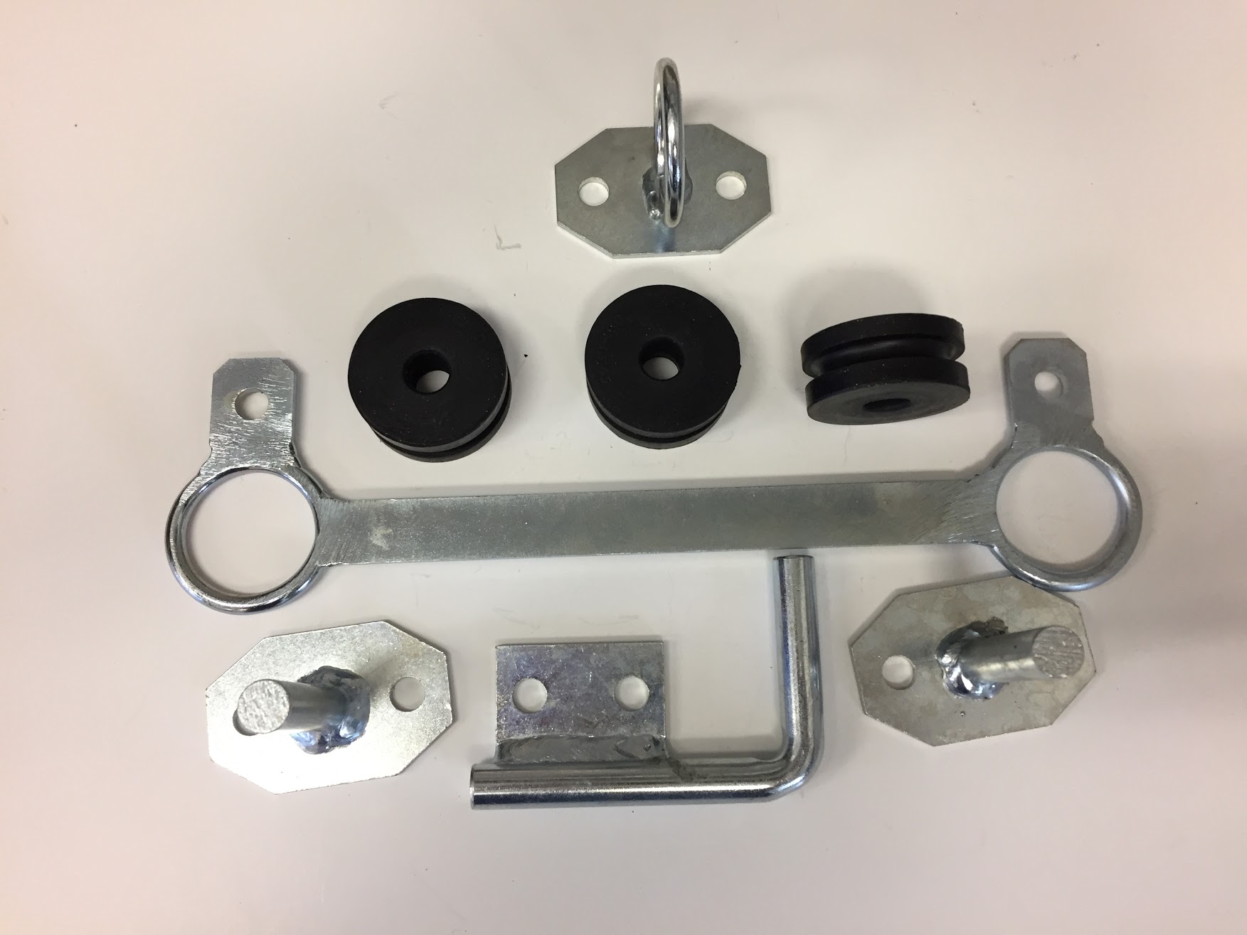
What I am calling the “Ring and Pin” Mounting system assembly from SNG Barrett looks like this:

Ring and Pin MK2 Exhaust Mounts
Usually the Parts Catalogue is pretty good at describing when component changes occurred in the manufacturing sequence, but in this case I was not able to find anything definitive.
Exhaust Hanger System as Removed from My Car
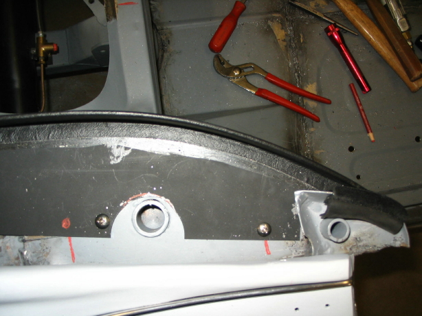
There are four exhaust hangers for the silencers and pipes. One is located centrally at the front of the silencers; one at the rear of each silencer; and, one at the back of the tailpipe – Bracket Assembly Locating Rubber Mounting at Wheel Arch.
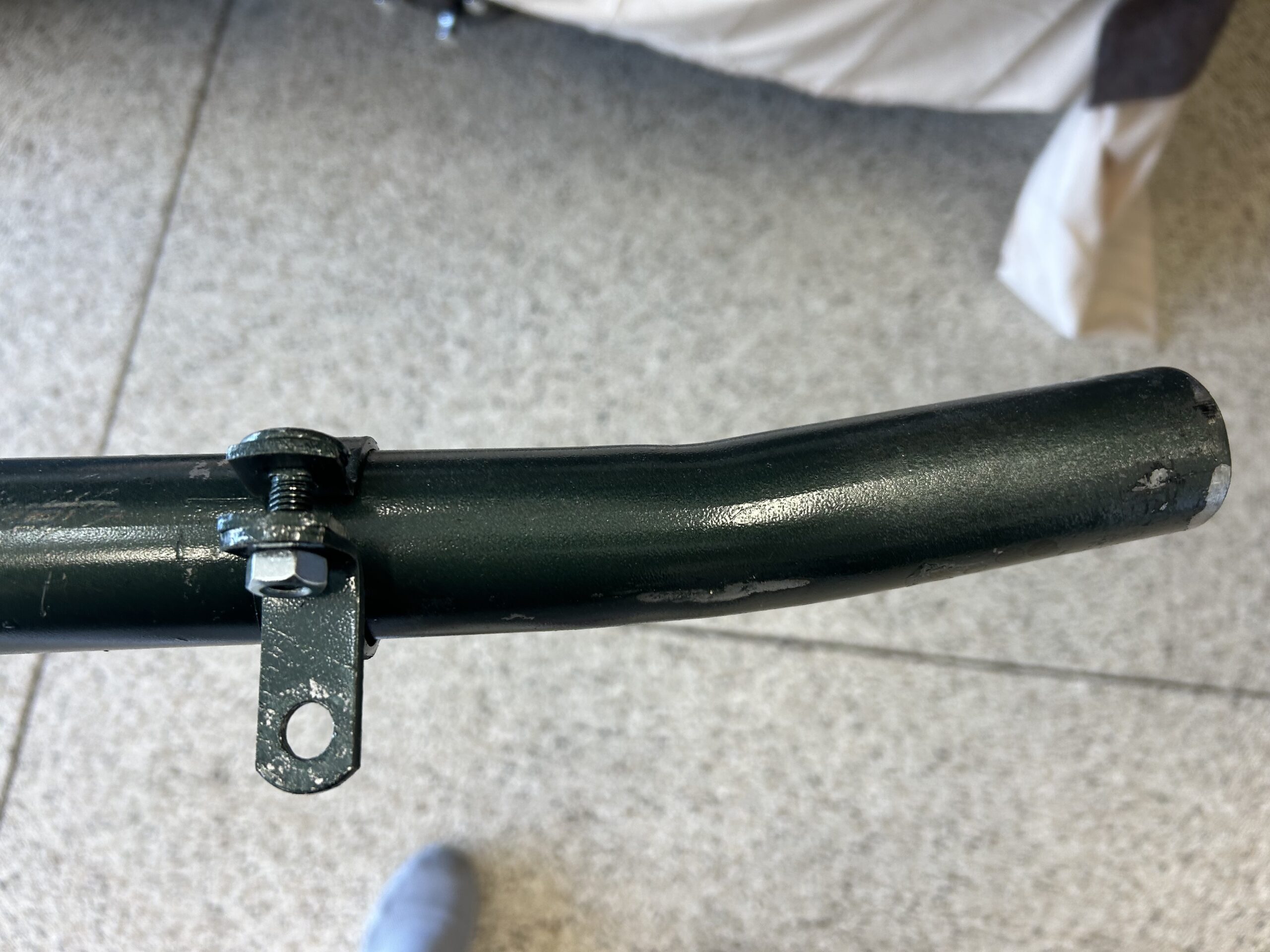
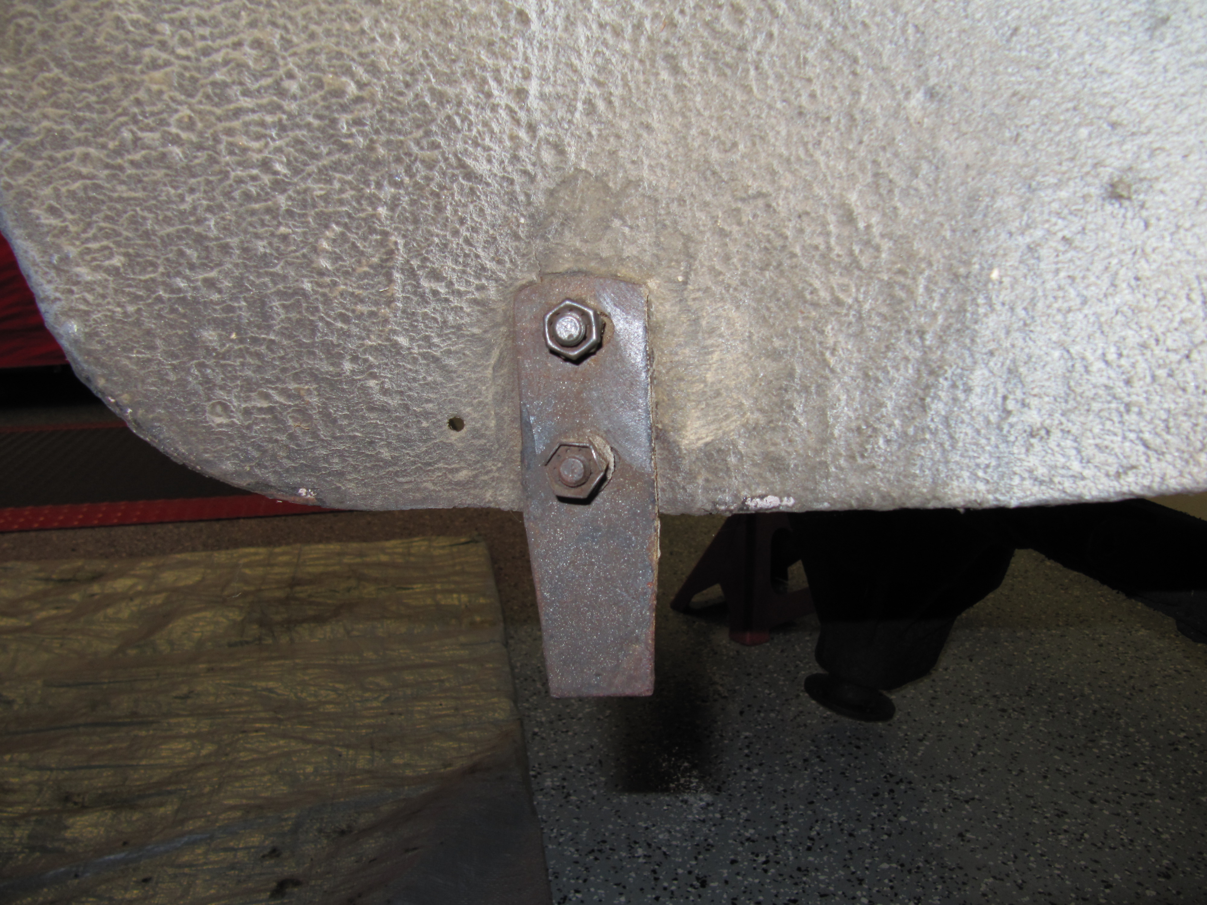
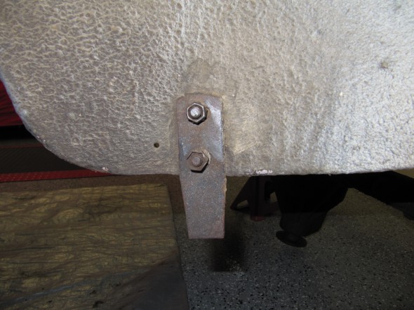
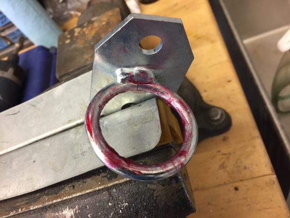
This is the bracket at the rear wheel arch minus its rubber fitting which had separated from the bond to the metal. The bracket is secured to the wheel arch with two 5/6″ – 24 x 3/4″ hex head bolts and nuts along with a “double-nut” for locking I am sure. I have not seen this type of nut before.
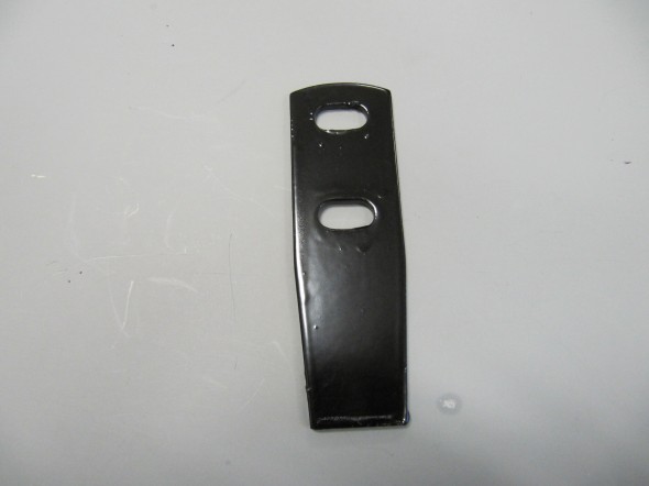
Rear Bracket
Rear Bracket
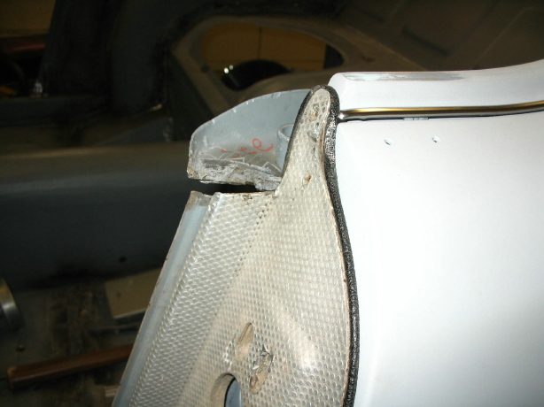
This image shows the remaining bits of the bracket on the removed tailpipes.
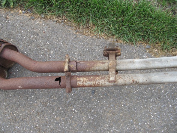
Exhaust Removed
It should be noted that if you look carefully, short bushings were used at the rear mount to align the rear tailpipes.
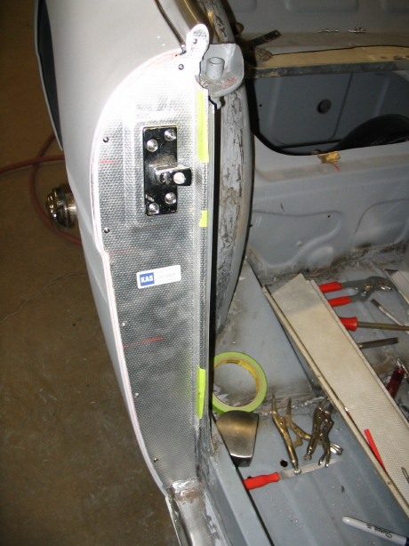
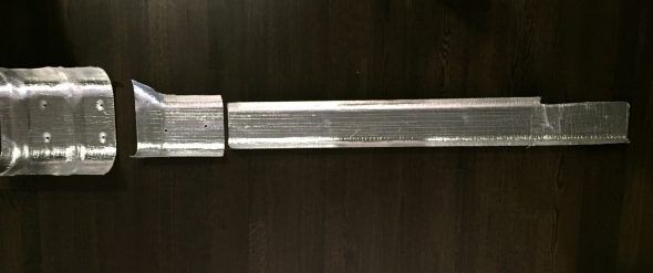
Exhaust Heat Shields
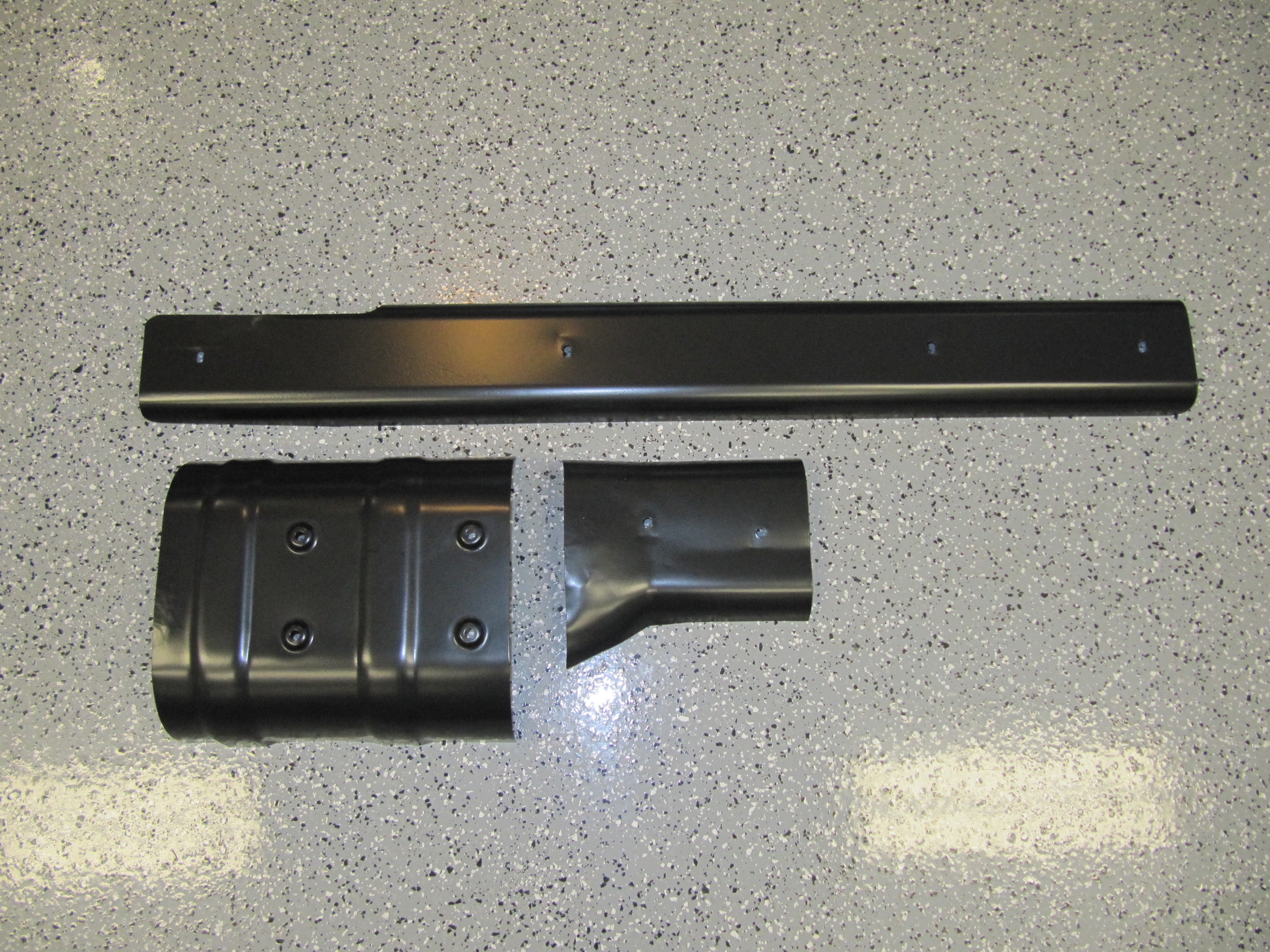
I cleaned the front, intermediate, and rear heat shields and had them media blasted and powder coated. The heat shields are mounted to the underside of the floor with a total of ten 1/4″- 28 x 1/2″ hex head bolts with shakeproof and flat washers.
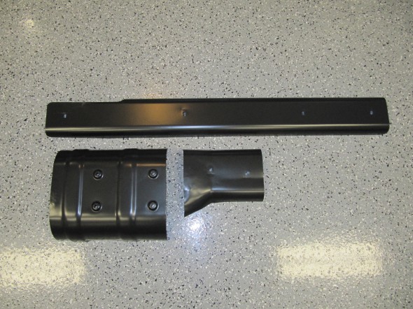
Powder Coated Exhaust Heat Shields
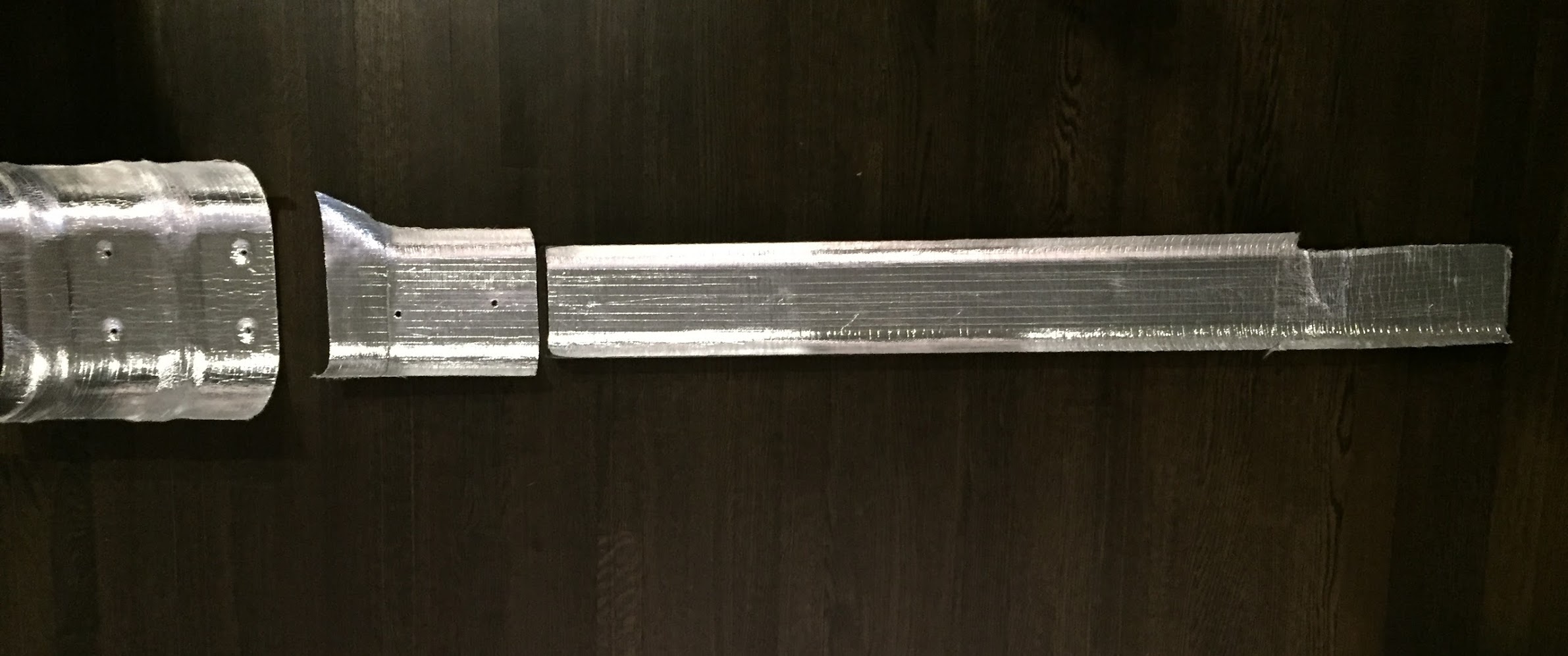
After powder coating I lined the underside of the heat shields with Thermo Tec’s Aluminized Heat Barrier with adhesive backing. I ordered a 24 x 48″ piece, Part number 1828-24×48 from PegasusAutoRacing.com. https://www.pegasusautoracing.com/productselection.asp?Product=1828. For trial fitting of the exhaust system, I went ahead and also installed the heat shields.
Three Exhaust Heat Shields with Thermo Tec Insulation

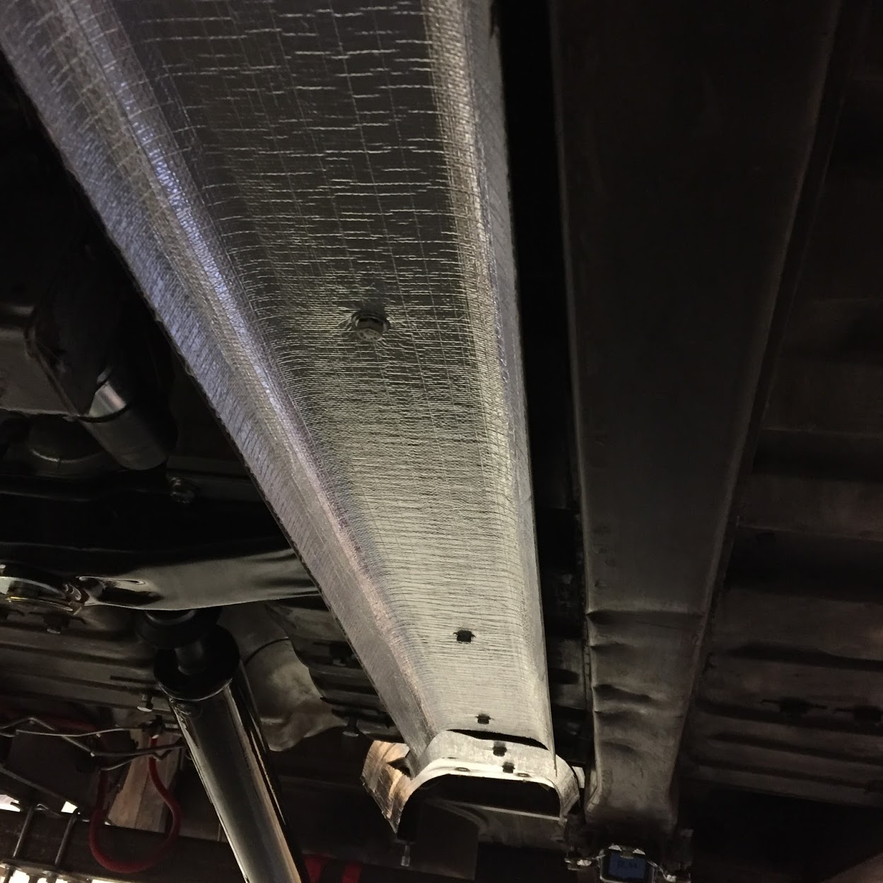
Forward Exhaust Heatshield Installed
Intermediate and Rear Exhaust Heat Shields Installed
The New Exhaust System Installation
I opted to use the more robust “ring and pin” mounting system though it is not what was originally on my car. The vulcanized mounts produced today unfortunately have a reputation for separating. Some owners have resorted to putting screws or bolts through the metal and rubber to hold the brackets together should the bond break.
I purchased a new stainless steel Bell exhaust system from SNG Barratt along with new sealing rings.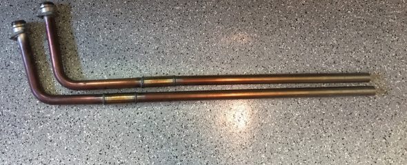
The downpipes are new but discolored because they were used for the engine run-in after rebuilding.
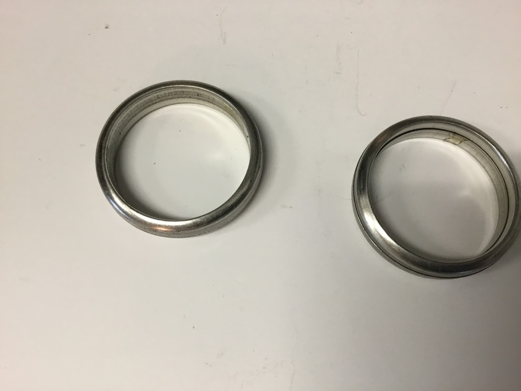
Exhaust Downpipe Sealing Rings
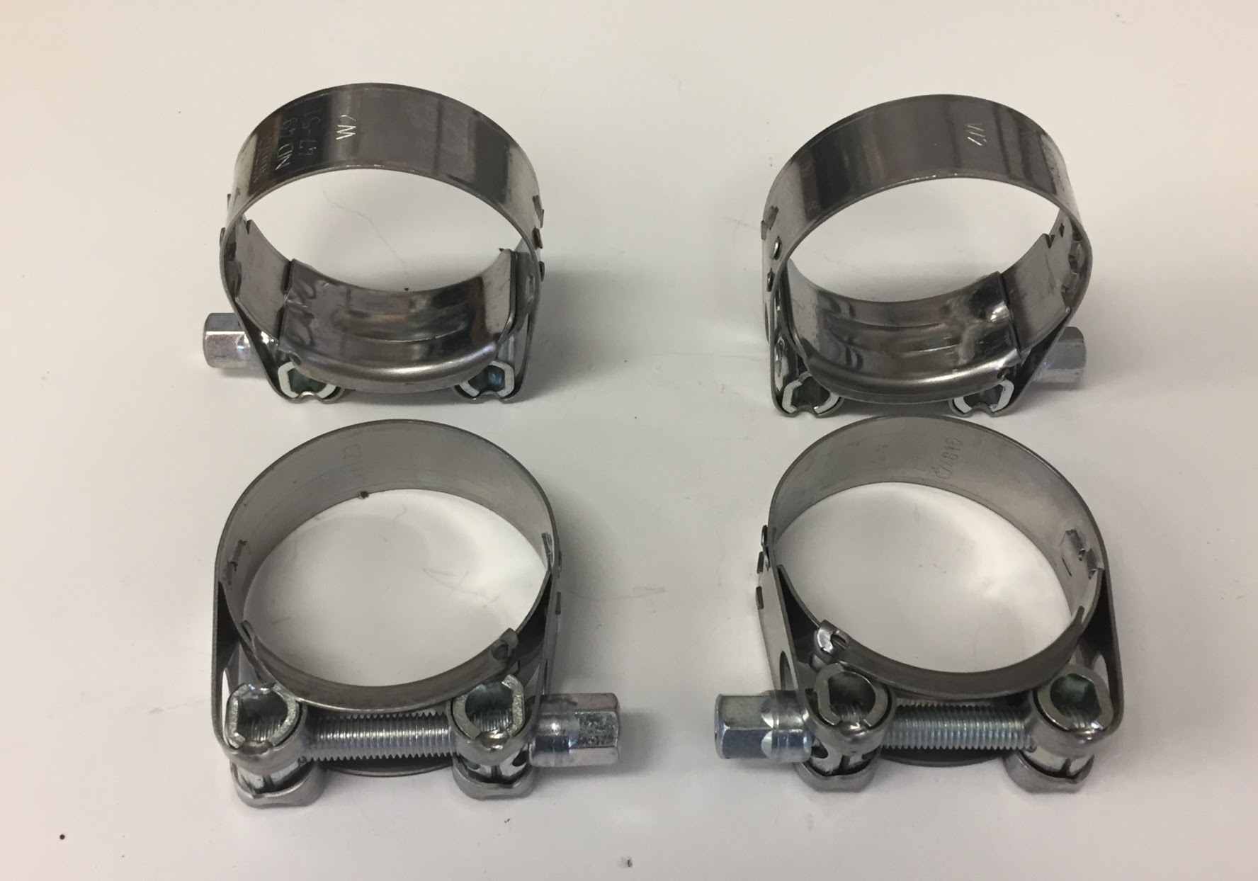
I also purchased exhaust pipe clamps from Terry’s Jaguar https://www.terrysjag.com. They sell clamps that are marketed as “Bell” clamps. I don’t know that they are, but I do prefer them to the hoop style typically available at auto parts stores. They don’t deform the pipes as the hoop-type clamp can do.These clamps are 1-7/8″ or 47-51mm.
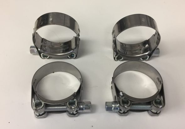
Bell Hangers for MK2 Exhaust Installation
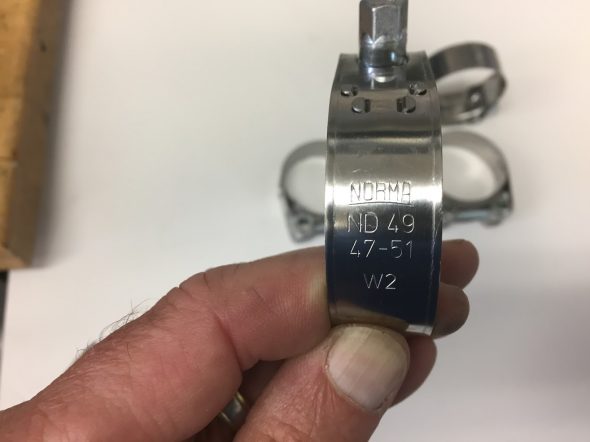
Bell Hanger 47-51 mm
After seeking advice from others on the various forums I began my installation. The only real advice I received was to hang all parts of the assembly loosely together before tightening. However, (at least in my case) I found that I could not fully follow the advice!
I took the advice I received literally and kept everything loose – the exhaust and the hangers. However, once the exhaust is in place it is practically impossible to tighten the “ring and pin” midpoint hangers to the car. So, I will slightly modify the advice I received to the following: Tightly secure the single hanging mount at the front of the silencers and the double “ring and pin” mount at the rear of the silencers to the car. One can leave the rear “ring and pin” mount in the LH rear wheel well loose. Then loosely hang all of the exhaust components.
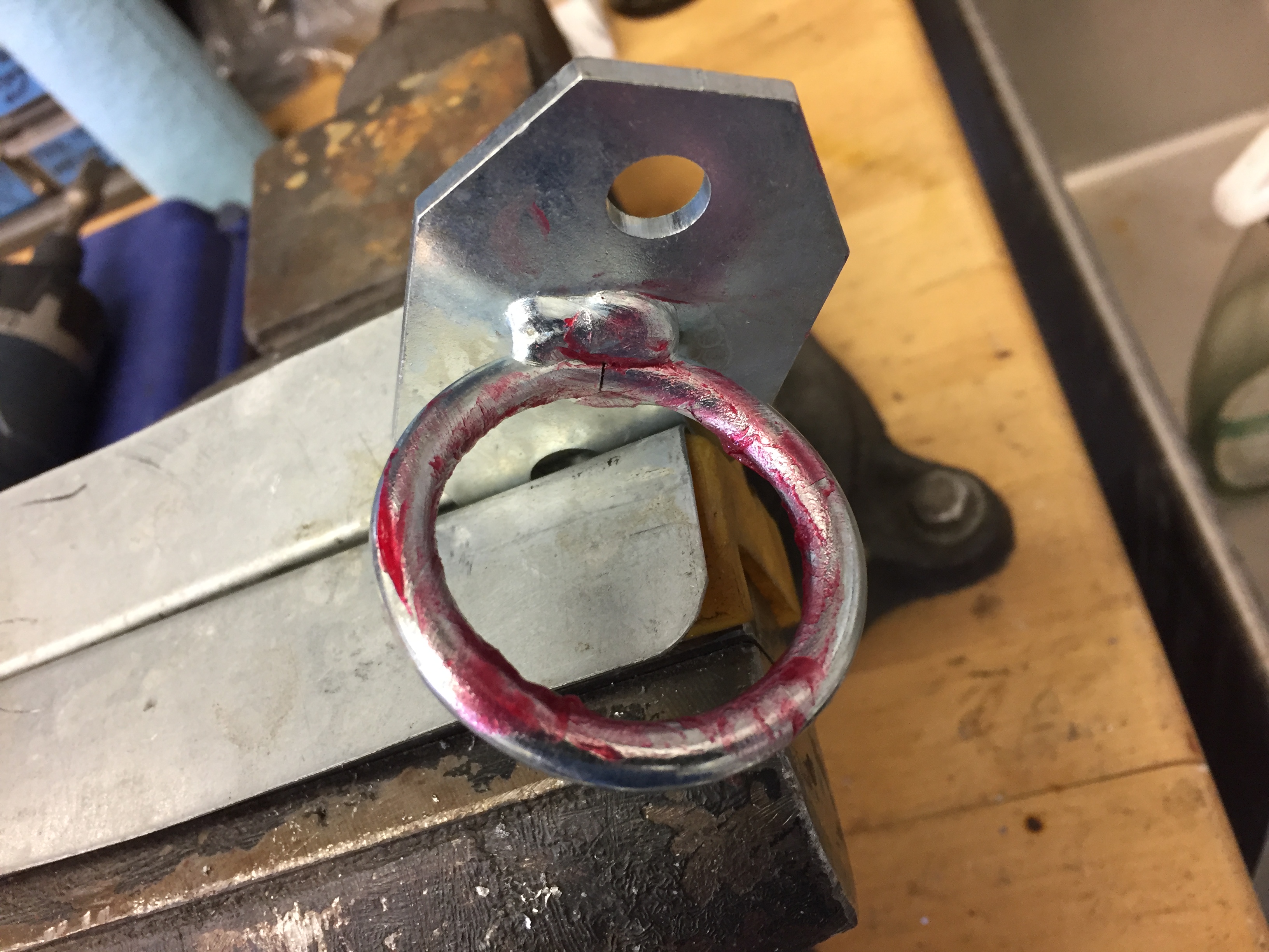
It is challenge to get the rubber bushes in the hanger rings. I heated mine in pot of hot water and I applied rubber grease to the metal rings. With the brackets in a vice I was then able to push the softened rubber bushes into place.
Rubber Grease on Exhaust Mount Ring

Rubber Bushing Installed in Exhaust Mount
New stainless steel studs (four each) were used in each of the exhaust manifolds for mounting of the downpipes.
Exhaust Manifolds to Downpipes
Beginning with both exhaust manifolds mounted tightly to the cylinder head (with new gaskets), I then slid the sealing ring and square mounting plate over the rear downpipe and loosely mounted it to the studs on the rear manifold with flat washers and brass nuts.
Exhaust Manifolds Mounted
Care must be taken to place the mounting plate on the pipe in the proper direction. One side of the mounting plate is concave to join properly with the sealing ring, while the other side of the plate is flat. Lock washers are not used per the parts catalogue.
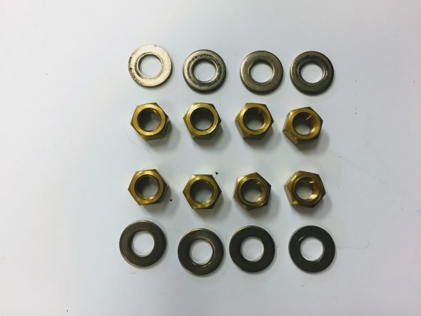
Exhaust Downpipe Washers and Brass Nuts
I was then ready to mount the front downpipe, but noticed that once the front downpipe is mounted, it would be impossible (for me anyway) to access all of the mounting nuts on the rear pipe to fully tighten each of them. So, before mounting the front downpipe, I went ahead and tightened each of the four nuts on the rear downpipe.
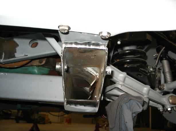
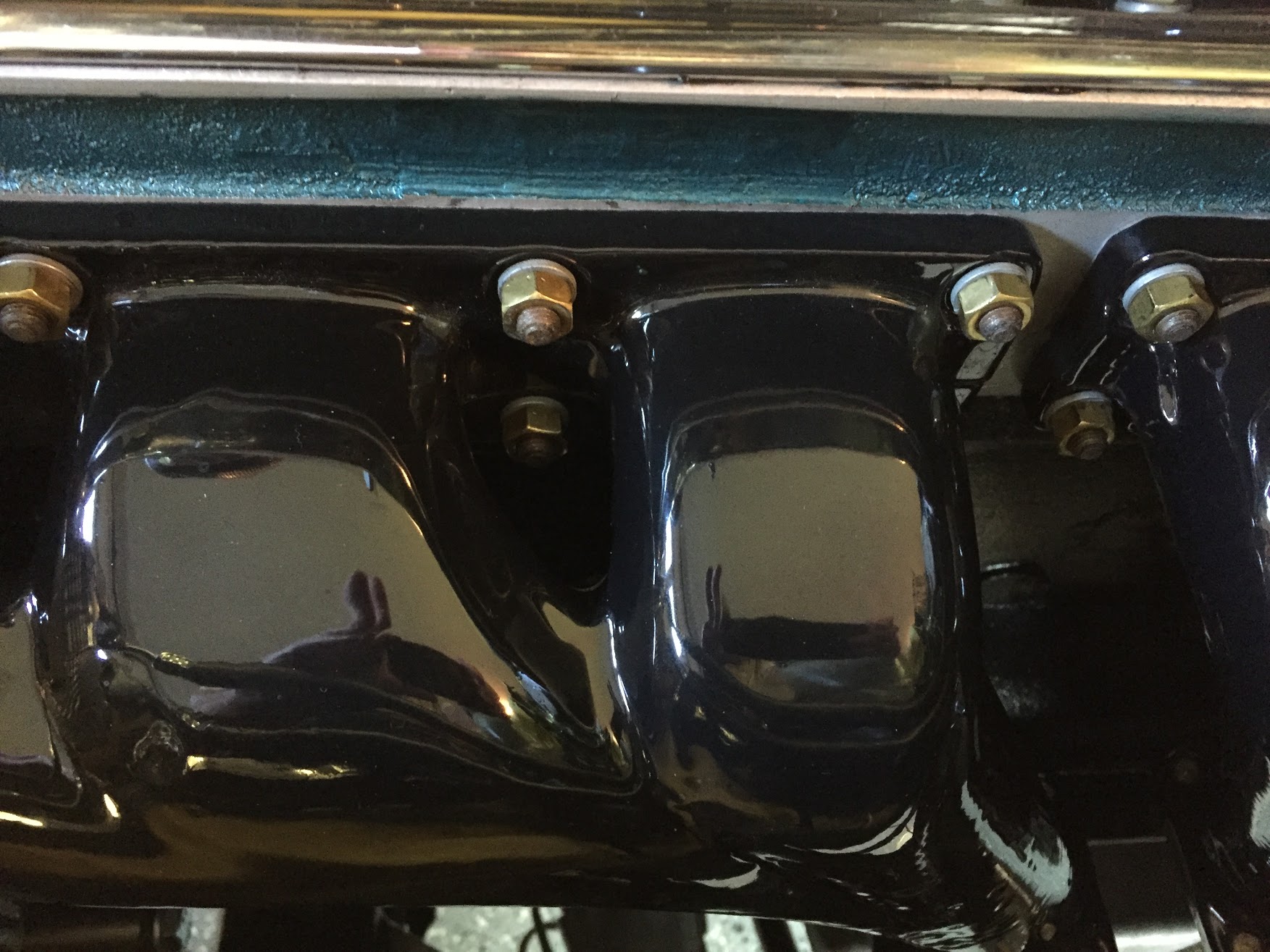
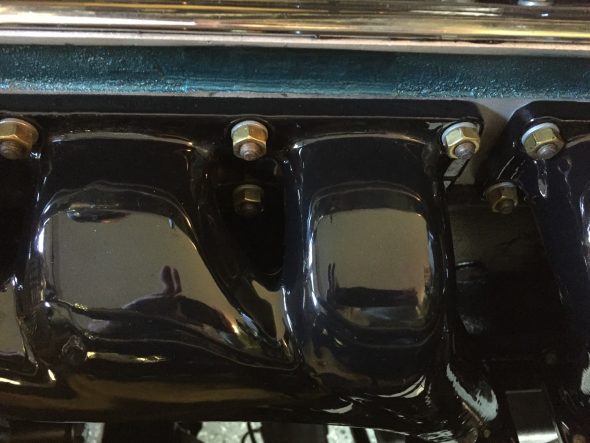
I then mounted the front downpipe to the front exhaust manifold with the four flat washers and brass nuts. In this case, I did mount the downpipe loosely until the complete system is configured. Note in the photo below that when fully tightened the mounting plate and the exhaust manifold mounting face do not join. The sealing ring is doing its job and providing the seal between the manifold and the downpipe.
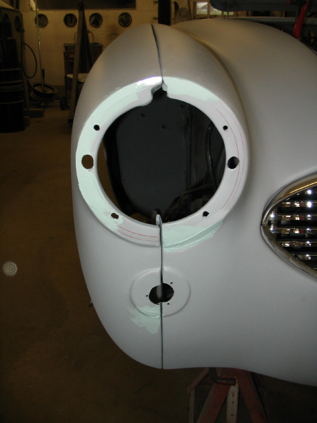
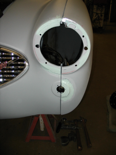
The triangle cut-out for exhausting heat from the engine bay has the alternative benefit of access to the downpipes mounts and to the steering linkage!
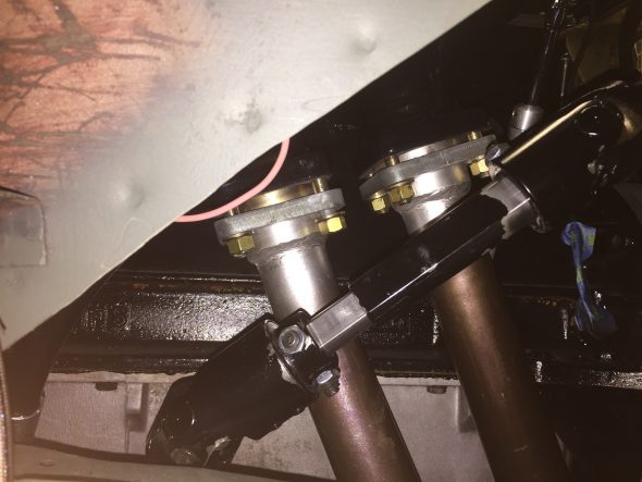
Exhaust Downpipes Front Mounted Loosely
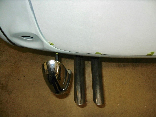
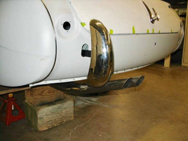
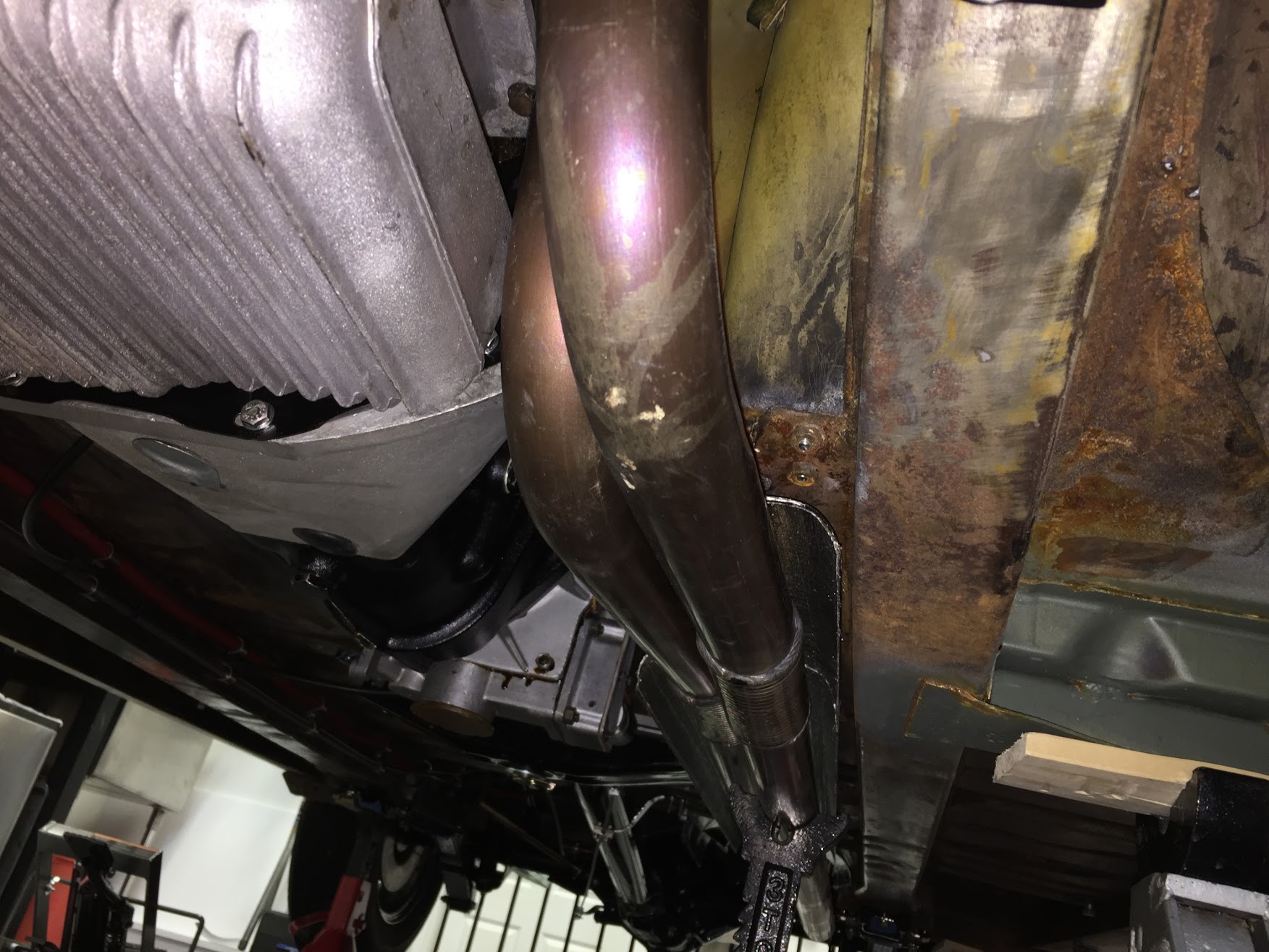
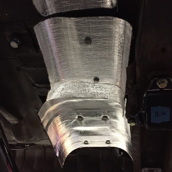
The image below shows the downpipes mounted under the car. Once on the lift I can get a much better photo, but in this case the car is simply on jack stands which makes good photography difficult!

Exhaust Downpipes in Place
On my final installation I will try to get a little more separation between the two downpipes, but what I have now if fine for my trial run of the car.
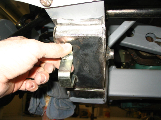
The central section of the assembly containing the twin silencers has a single front mount and the double mount for the “ring and pin” assembly at the rear. I must say the Bell system fit perfectly and was fairly easy to mount. I slid the center section onto the downpipes and loosely fit the rear of the section to the “ring and pin” mounts. I found this to be pretty easy to do. However, I found getting a bolt and nut secured at the front mount is extremely difficult requiring patience and long slender fingers. I have patience but not the long slender fingers! Using a floor jack to slightly lift the front of the silencer section (the welded bracket joining the two silencers is the perfect place) makes inserting the bolt and nut a little easier than if the assembly was hanging free.
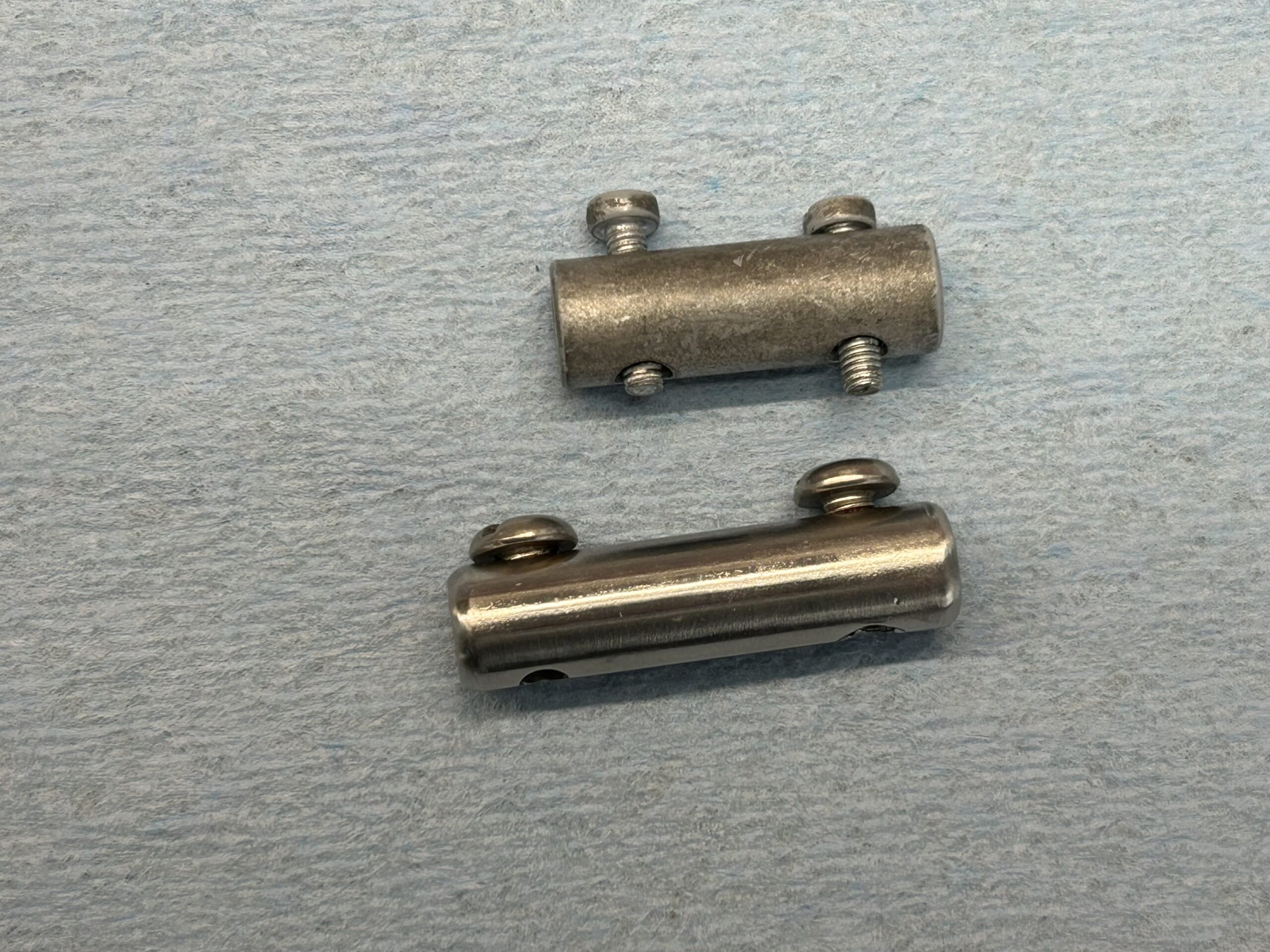
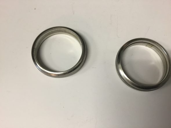
I also discovered that my original bonded hanging mounts are slightly longer that what is now sold (at least by SNG Barratt). It is difficult to tell in the image below but I think you can make out the difference. I ended up using my best original hanger rather than one of the new ones. It made the job a bit easier.
Old and New Hangers
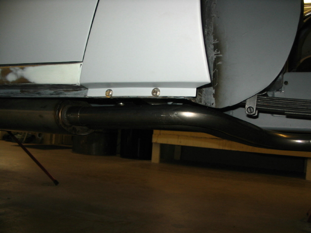
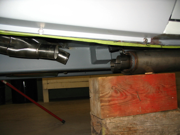
Finally, after bolting the rear mount ring bracket and rubber bush to the tailpipe section, I pushed the tailpipes onto the silencer section pipes and slid it into place on the rear mount previously secured to the car.
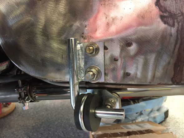
Exhaust Tailpipe Rear Hanger
I then retraced my steps and firmly tightened all connecting points. With the exception of the front silencer mount this job turned out to be quite a bit easier than I expected. The Bell system is a high quality product with a fit that is spot on.