The time has come for painting the Bugeye!
Color and Painter Selection
The short list for paint colors included Nevada Beige, Old English White and Cotswold Blue. The Nevada Beige and Old English White were factory colors available for the Sprite in 1959. The Cotswold Blue is period correct in that it was available at the time, but not for Austin-Healey Sprites. Slightly different variations of Cotswold Blue were used on Jaguars, Triumphs, Rovers and perhaps some other makes. We zeroed in on the Jaguar paint code as produced by Glasurit. Glasurit Line 22 was the single stage urethane topcoat paint used originally we believe. We will be using Glasurit 55 which is a basecoat/clearcoat urethane system.
This was a data sheet we located on the Austin-Healey Experience Forum. It provided information on the Jaguar version of the paint:
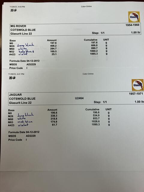
Cotswold Blue Glasurit codes
This is the actual paint that we used:
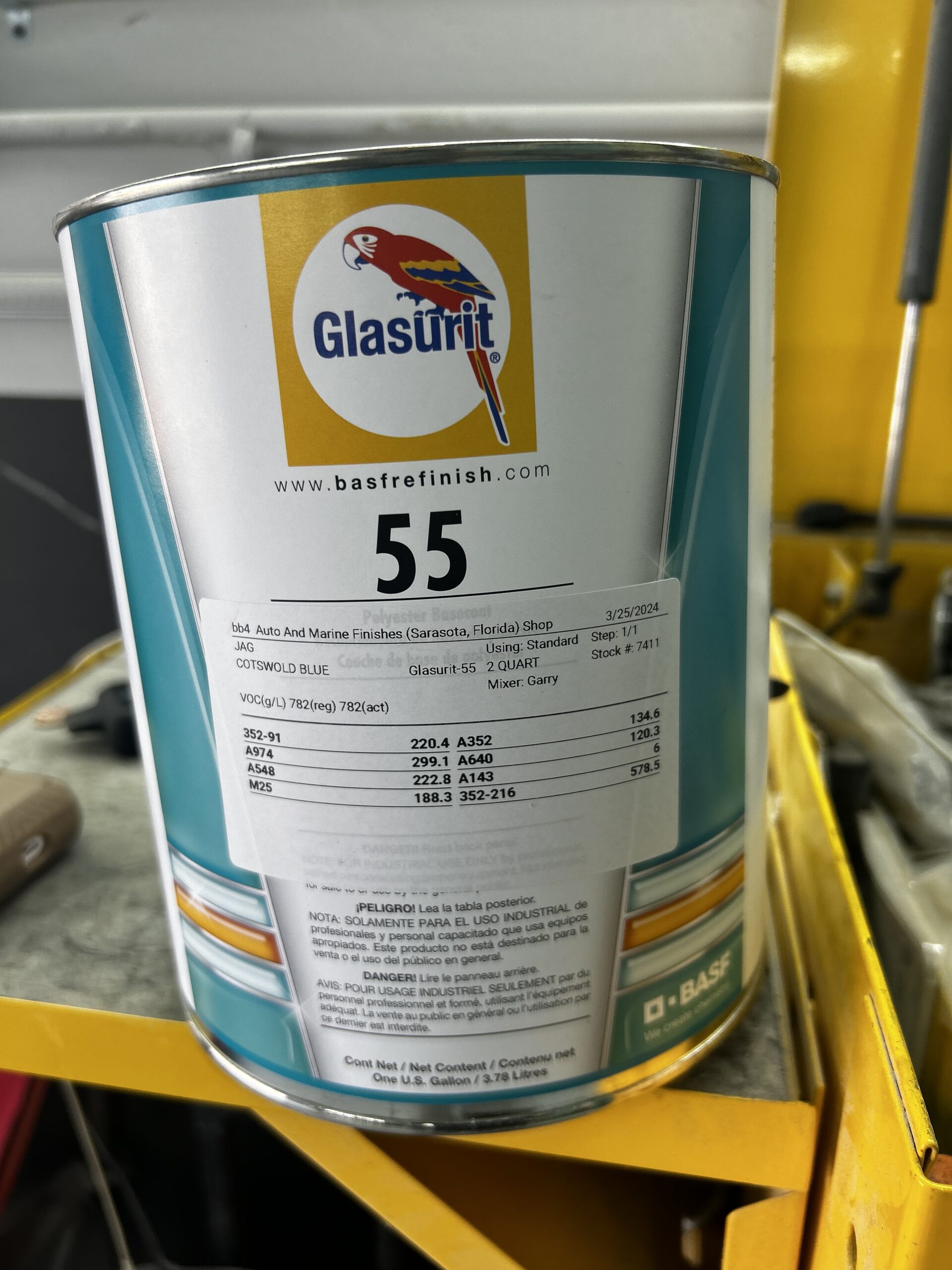
Glasurit Cotswold Blue 55
We are hoping that the end result will look similar to the Jaguar XK 140 below:
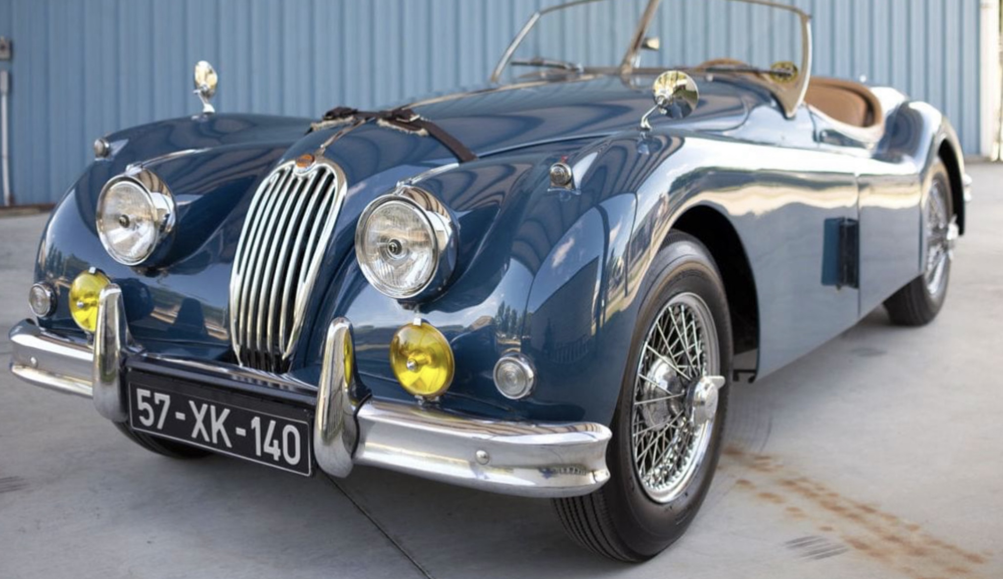
1957 Jaguar XK-140 Cotswold Blue
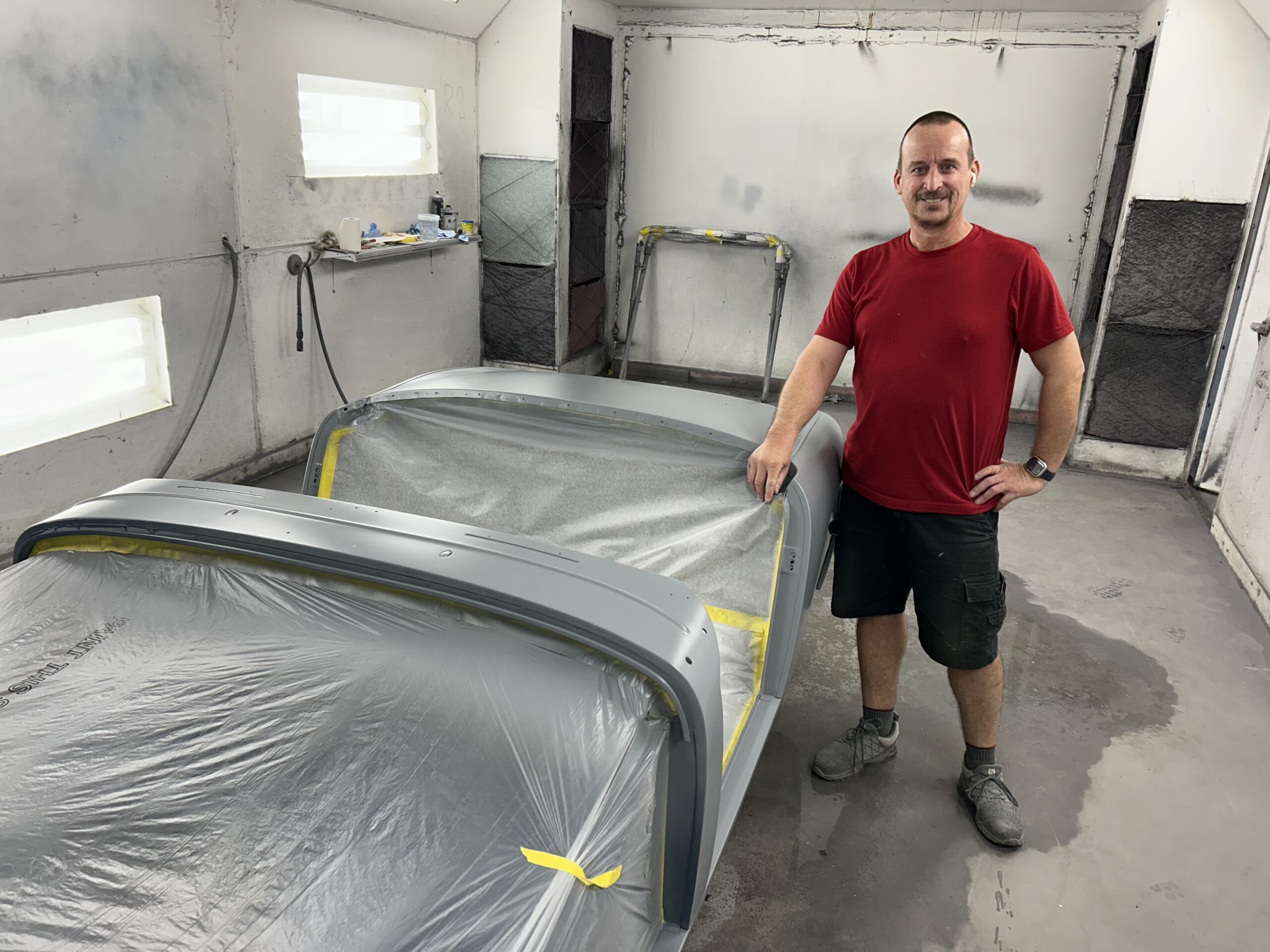
The next task was to find a painter. Unfortunately, Jeremy Turner who painted the Bloody Beast is a long way away in Virginia. By way of word-of-mouth we located Gabor Fodor in Sarasota who has his own painting business. As with Jeremy, Gabor owns a one person operation which appealed to us. We put a call out to the Paradise Coast Austin-Healey Club membership to see if anyone had a truck and closed trailer who was willing to help us get the Bugeye to Gabor’s shop. Amazingly four members immediately offered to assist. Gary Cox arrived at the house on March 5, 20024 and we delivered the Bugeye to Gabor that morning. Thank you Gary!
Undercoating Protection
The underside of the Bugeye is in such great shape and looks so good that we did not want to cover the surface with undercoating, but we did want to add some protection against road rash in the wheel arches. We considered Raptor Bed Liner but after consulting with Jeremy we decided to use a product called Rock-It XC made by SEM. This is the data sheet with instructions for the product: Rock-It XC Data Sheet Instructions
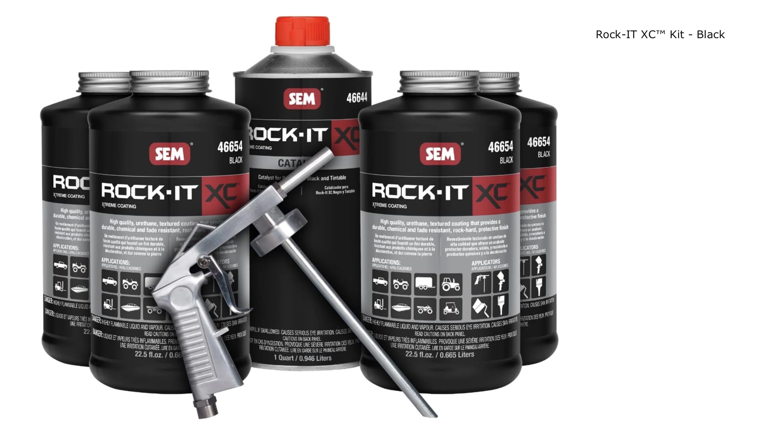
Rock-IT XC
Gabor did a great job of masking off the area to be treated and then applied a sealer to the body before spraying the Rock-It XC.
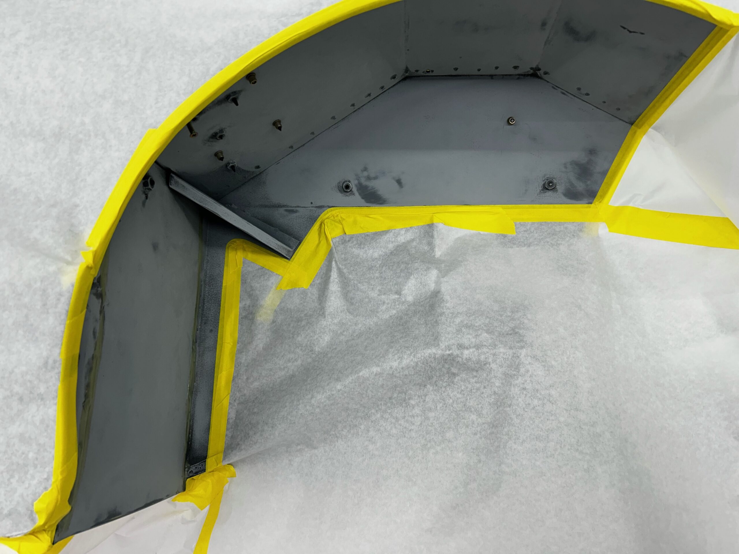
Masking for Rock-It 1
Masking for Rock-It 2
Masking for Rock-It 3
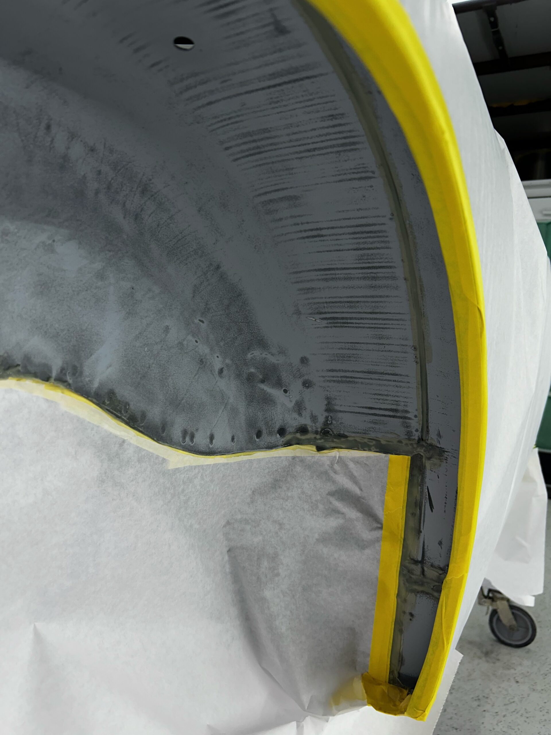
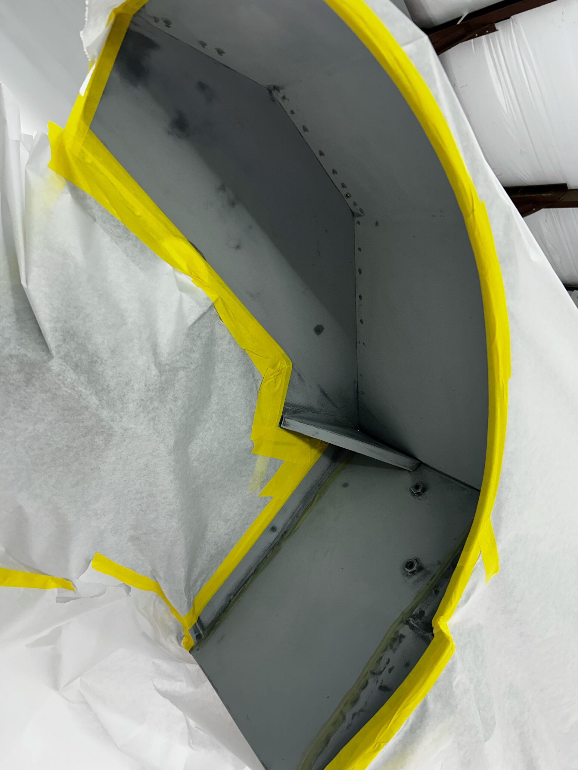
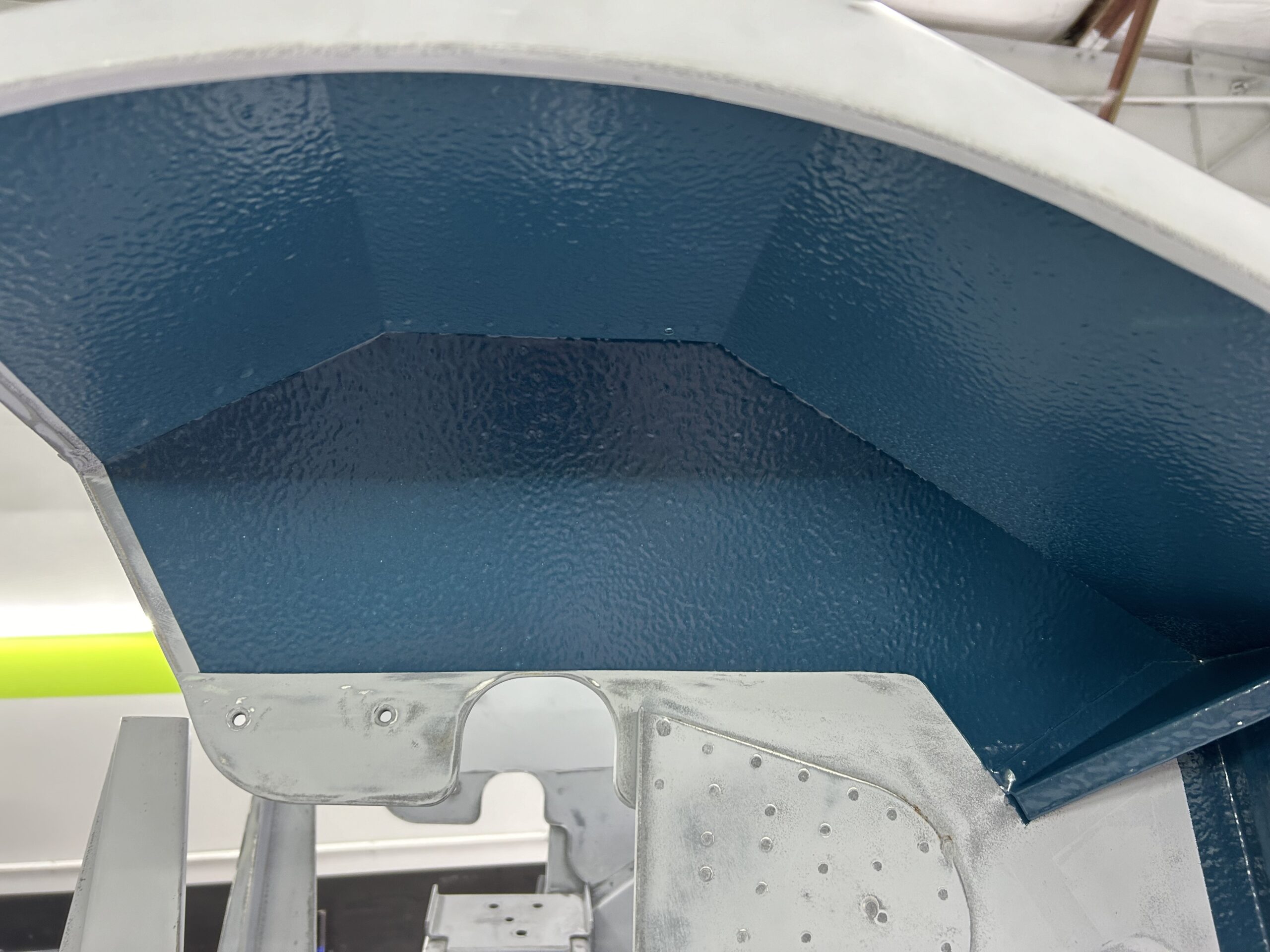
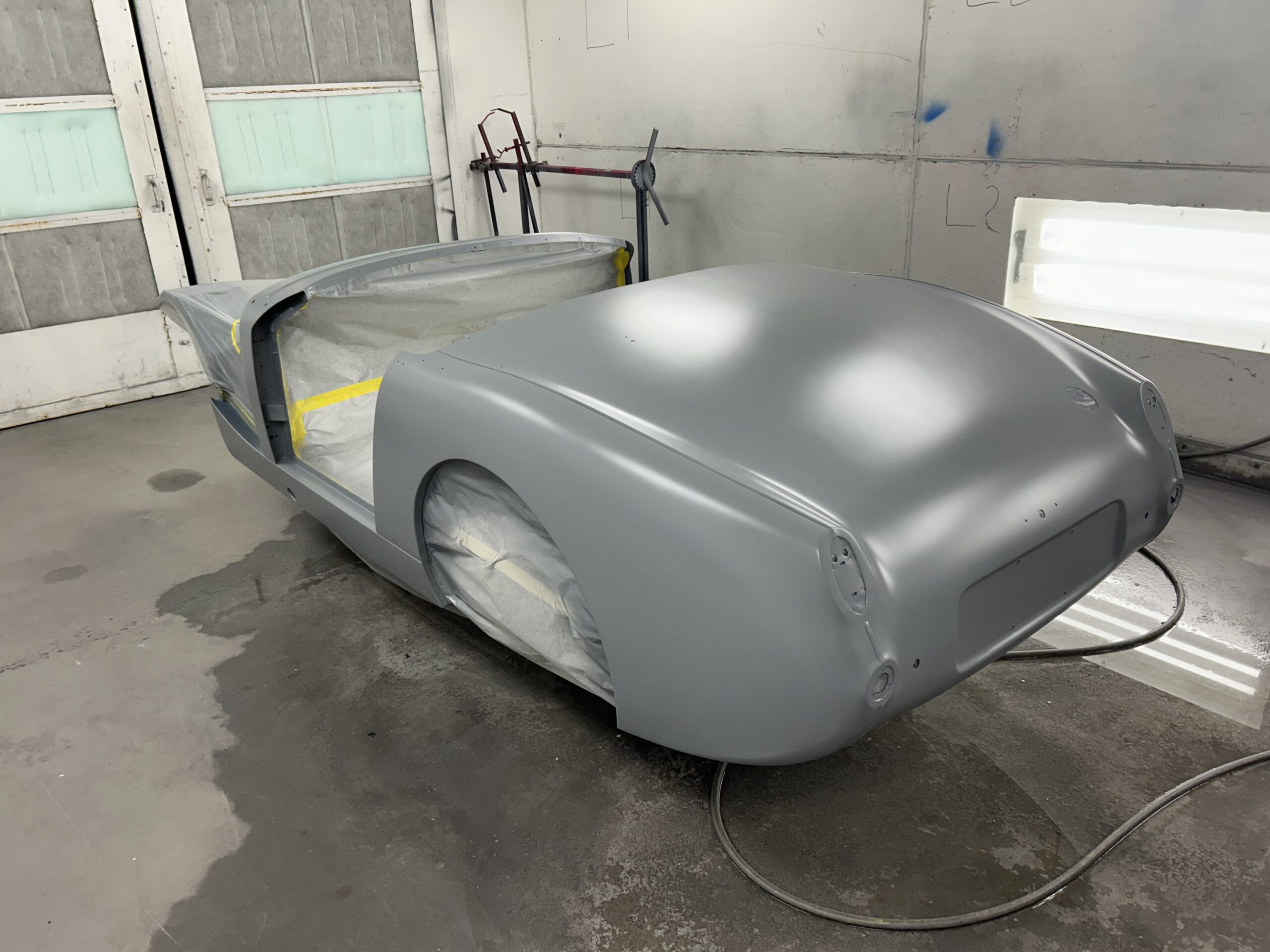
The Rock-It XC product can either be sprayed on as black and left that way or it can be top coated with the body color if you like. However, it can also be purchased in a tintable mix with directions on how much paint color to add to the product to achieve the desired effect. We went with the tintable version and will just have to wait and see how well it matches up with the body color. By adjusting the air pressure in the application gun one can also vary the texture of the product on the surface. We chose heavy smooth which calls for 65 psi in the gun. We are very pleased with the results. The last shot below shows the texture.
Front Inner Fender
Front Inner Wing 2
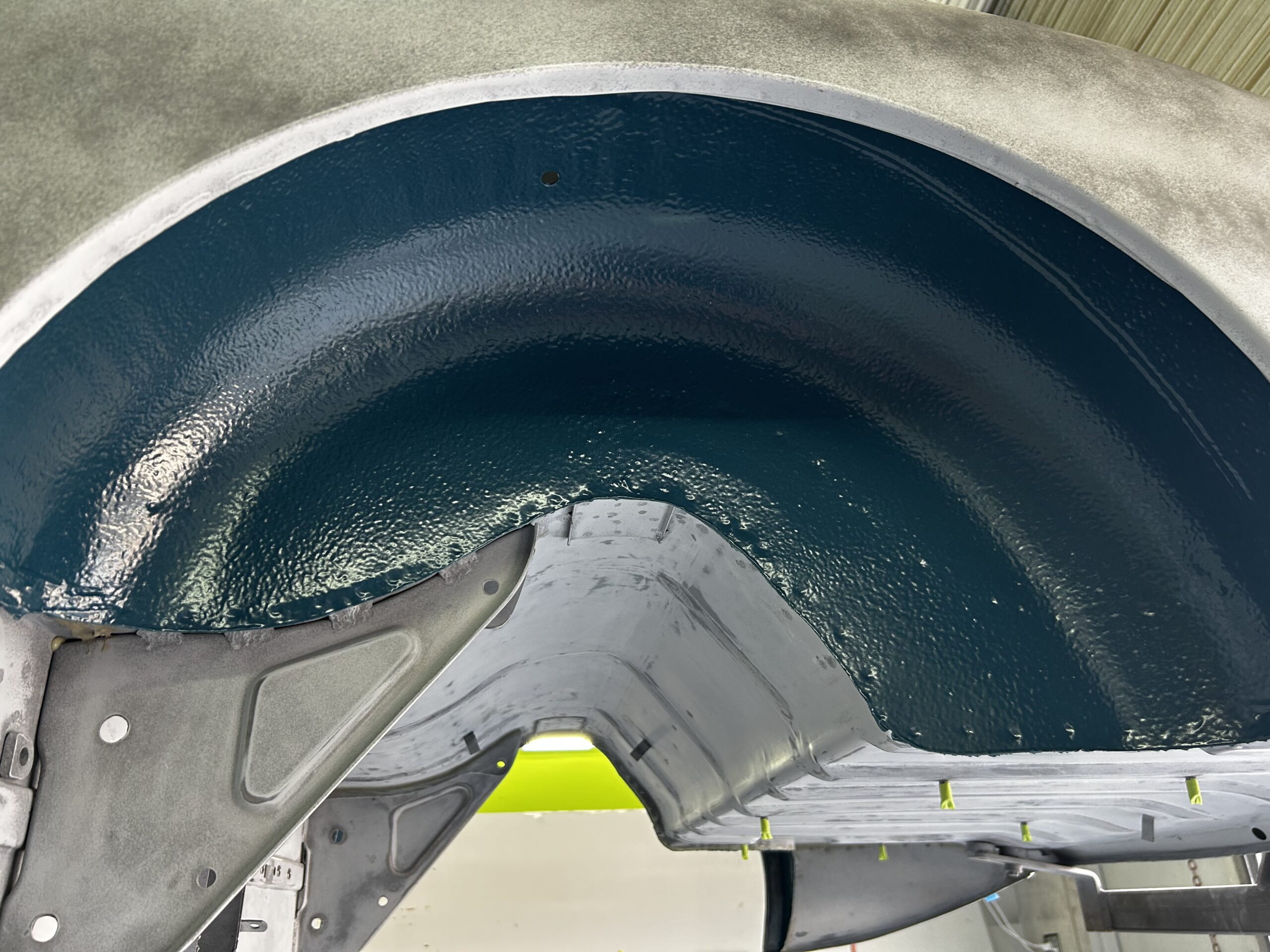
Rear Inner Fender
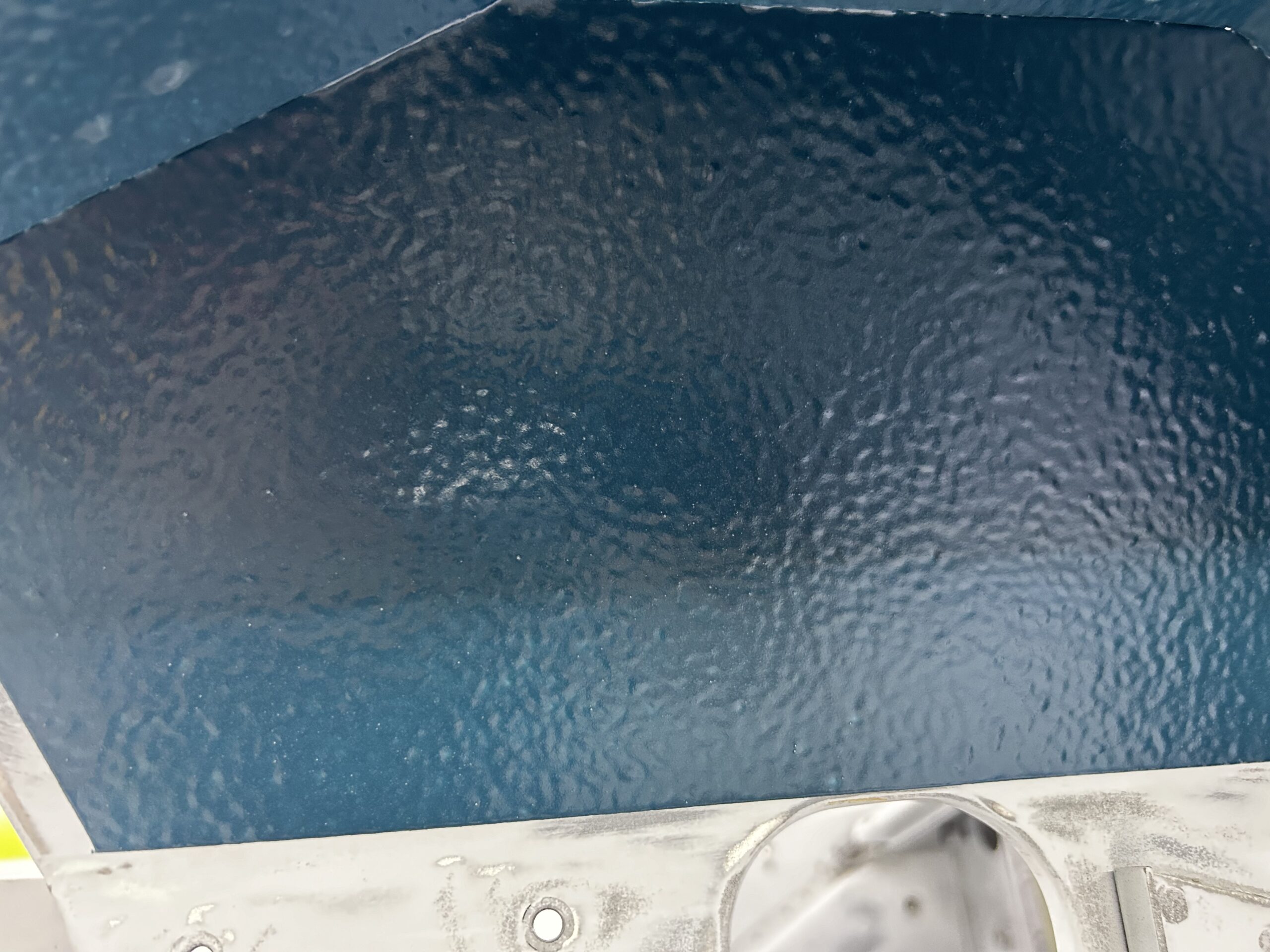
Heavy Smooth Texture
Seam Sealer and Sealer
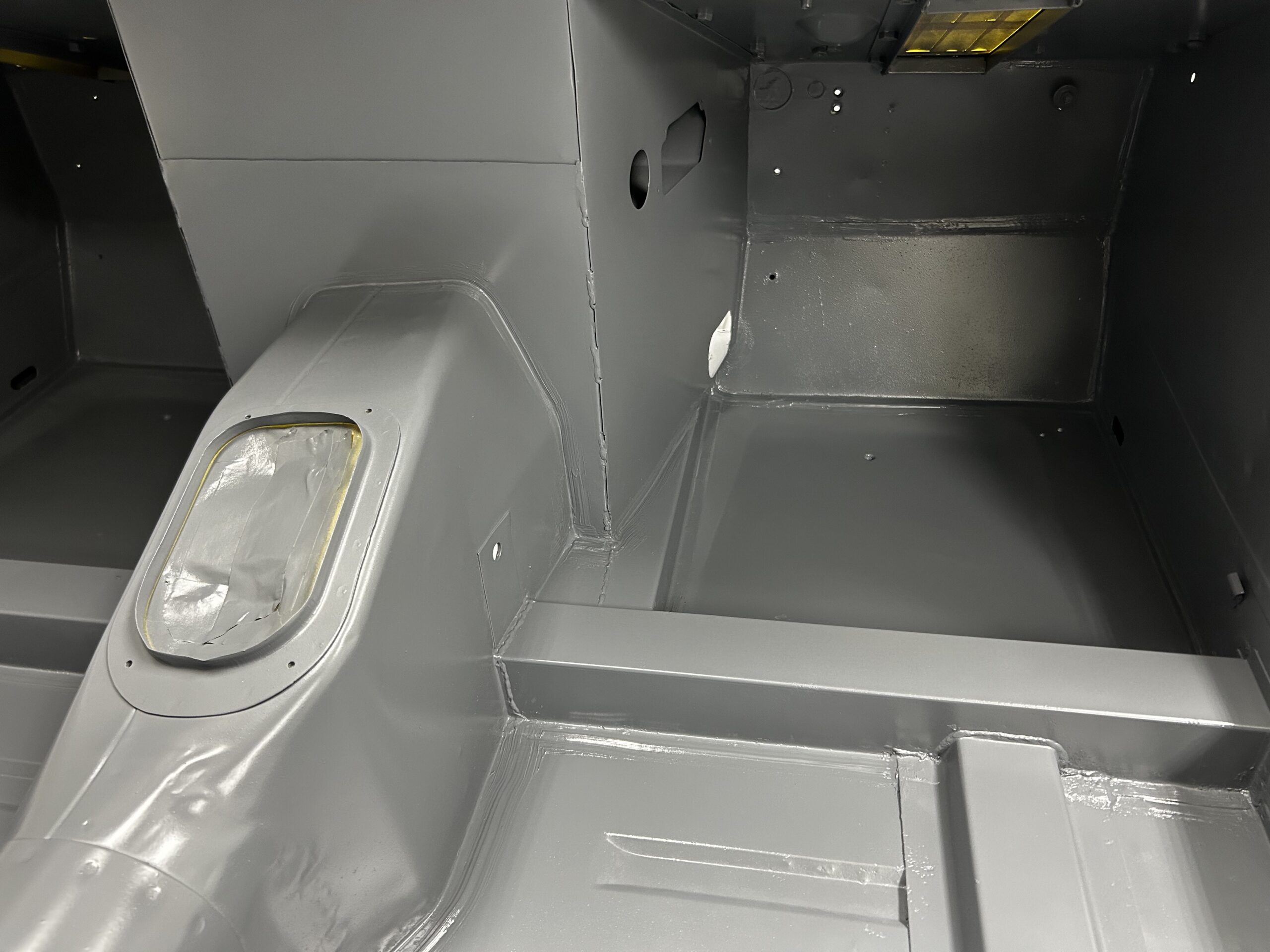
The next job Gabor undertook was seam sealing in the interior. We used a urethane 3M seam sealer for this. Here are a few of the images after the seam sealer was applied:
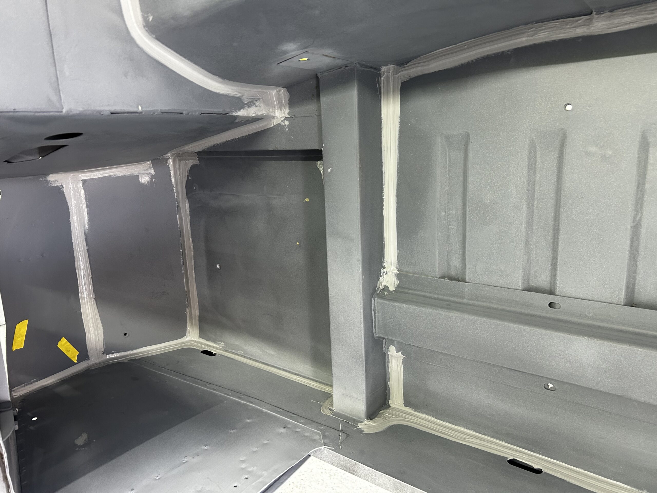
Front Interior Seam Sealer
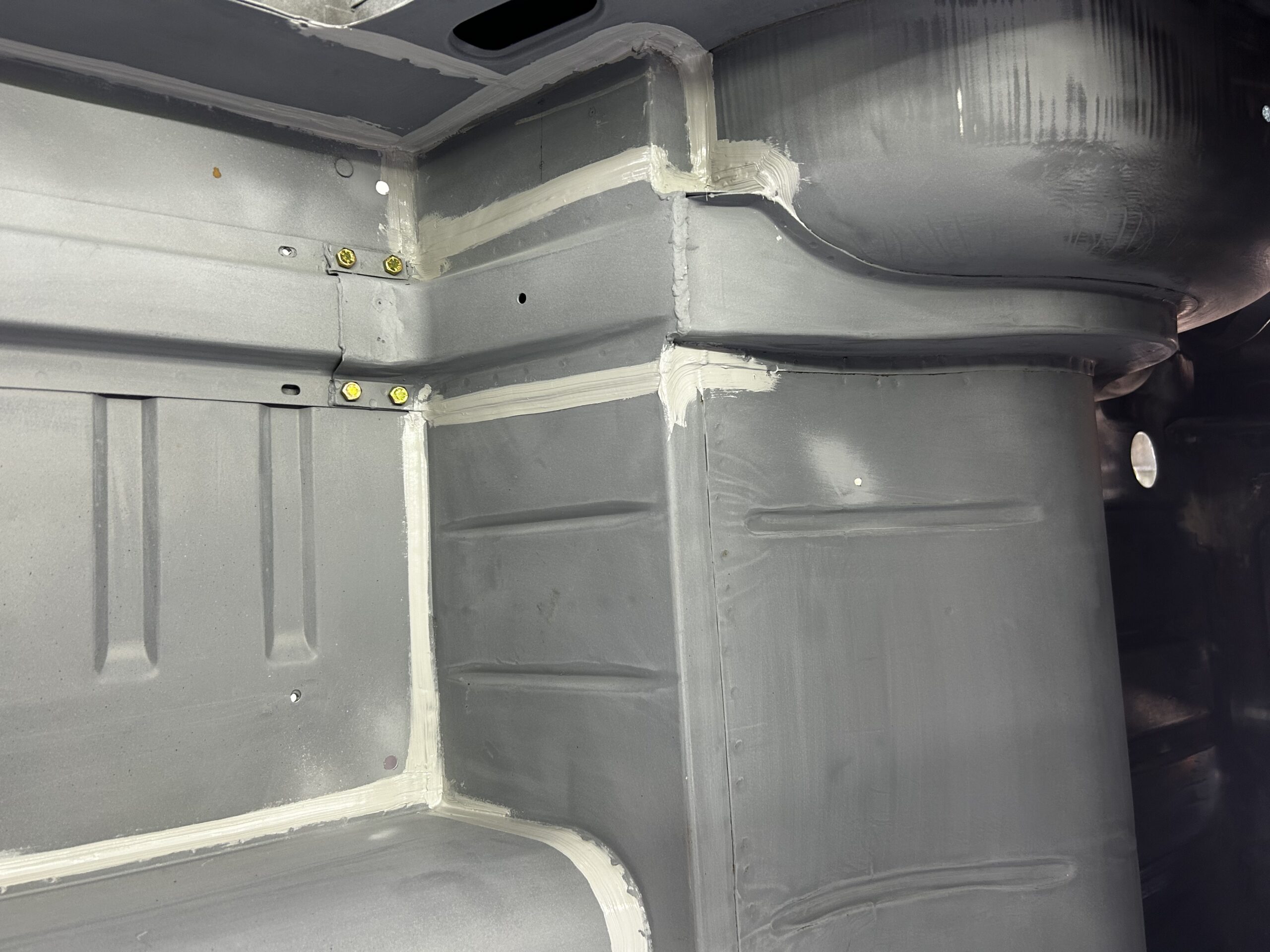
Rear Interior Seam Sealer
This is the sealer we are using before paint:
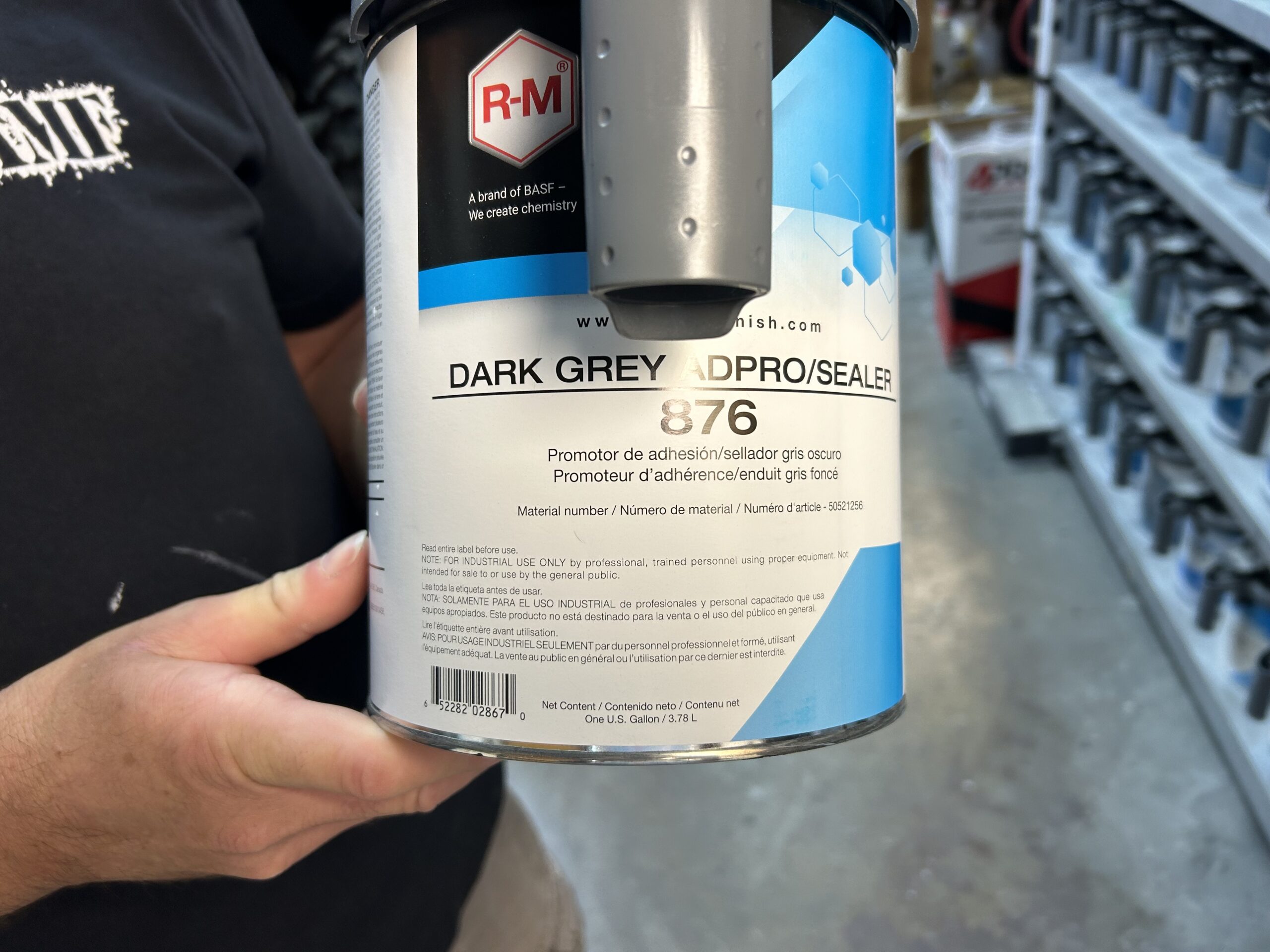
Sealer
Boot Sealer
Interior Floor Sealer
Front Interior sealer
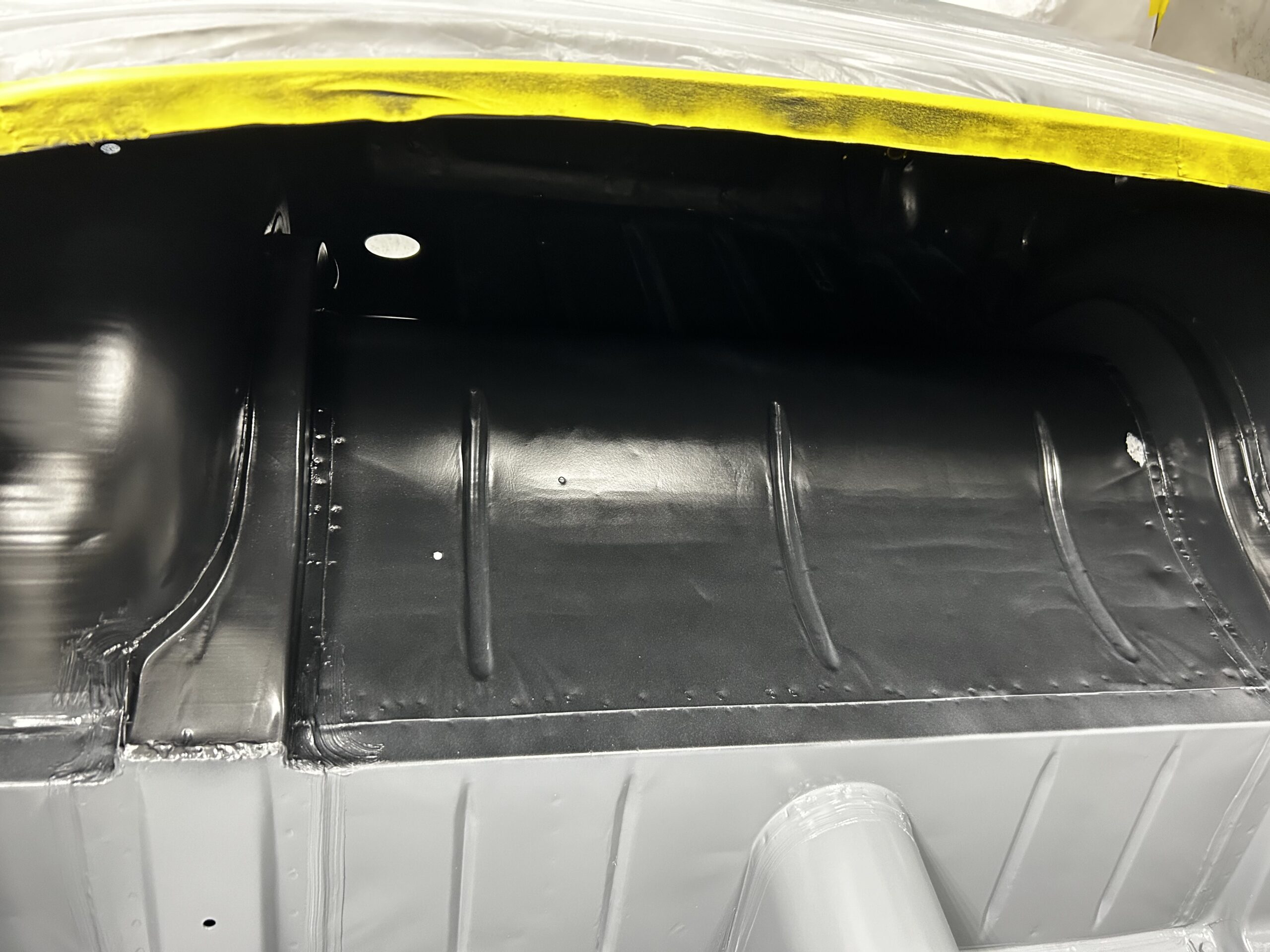
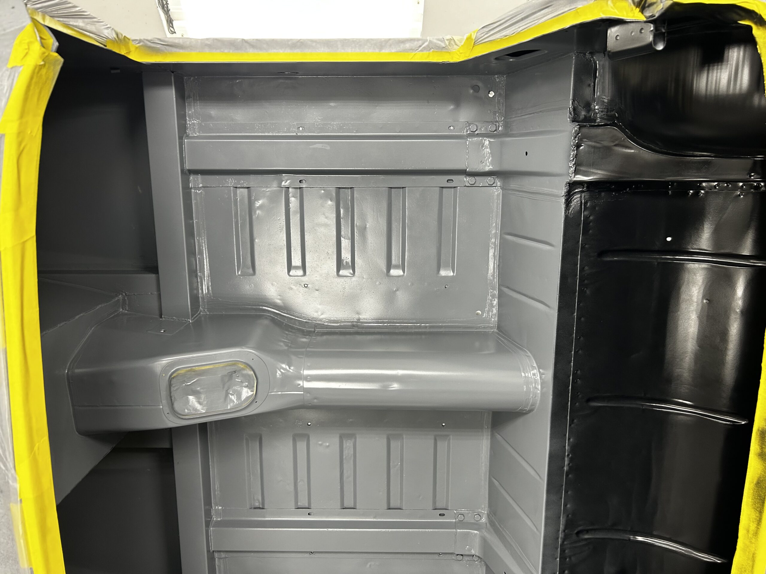
Interior Paint
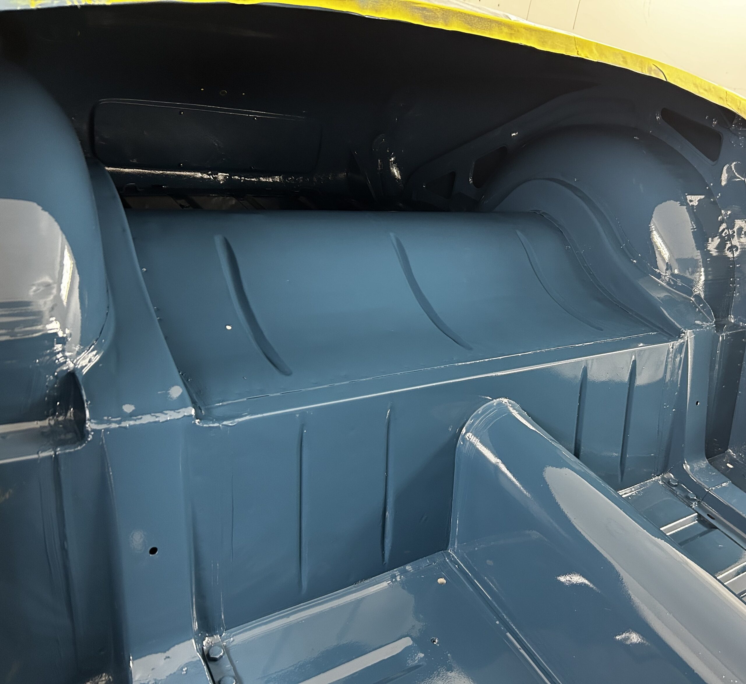
Rear Interior
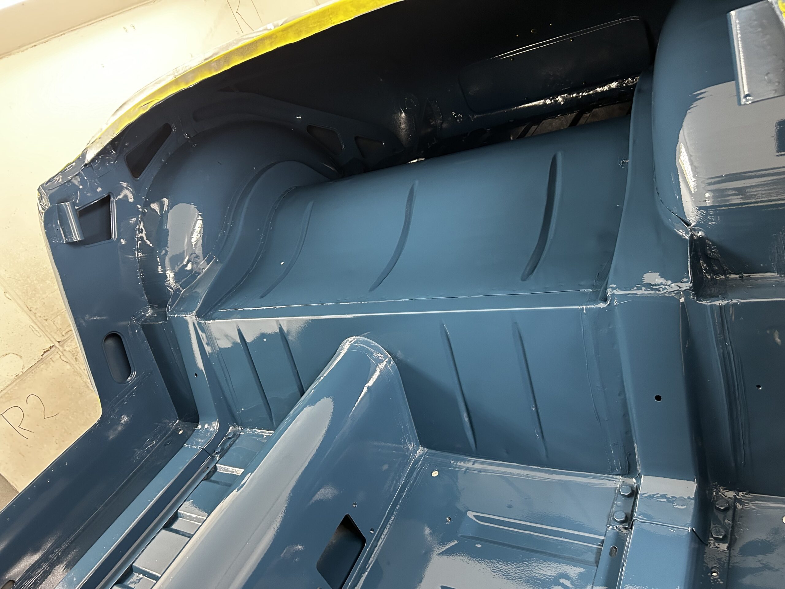
Rear Interior 2
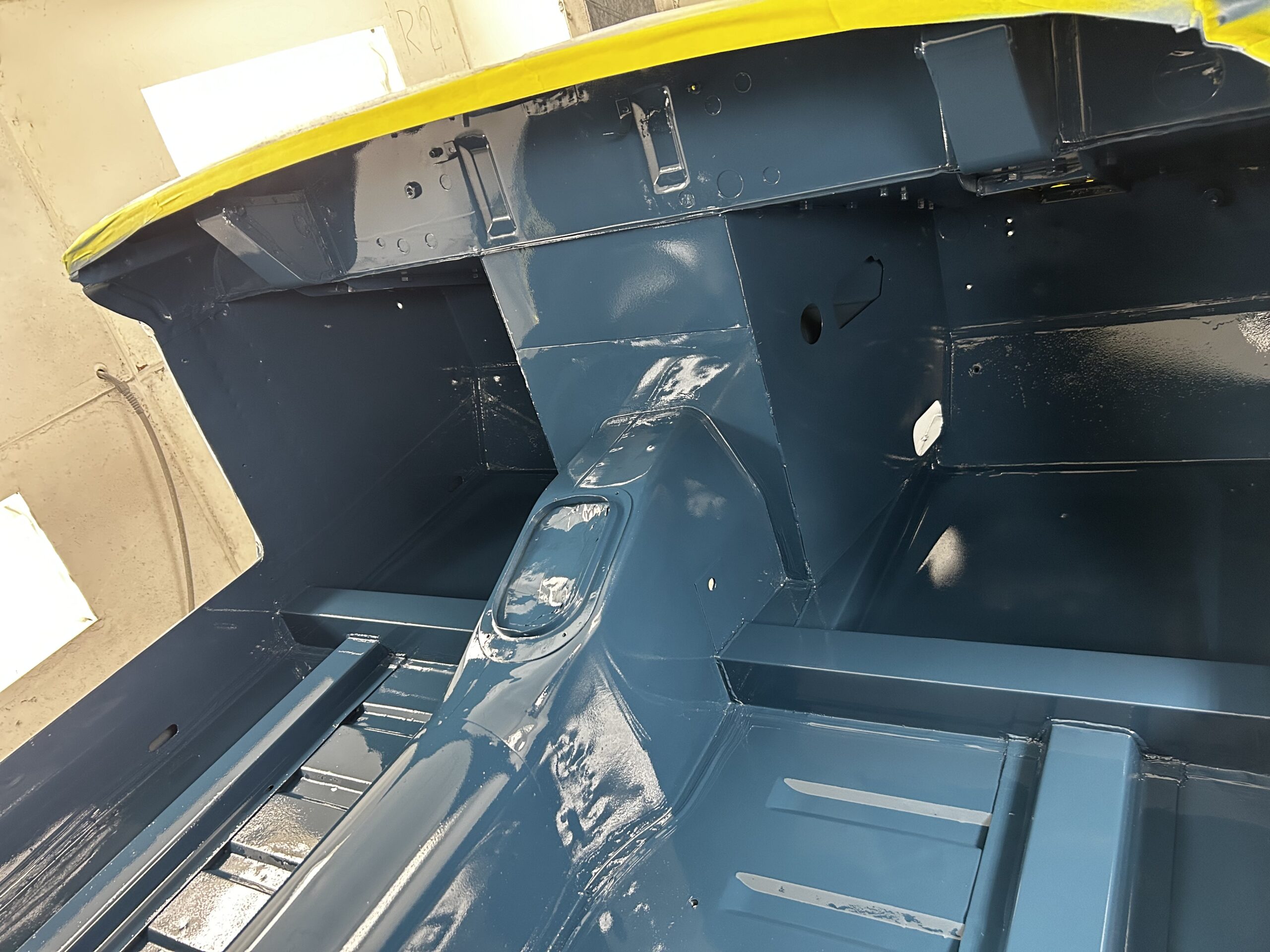
Front Interior
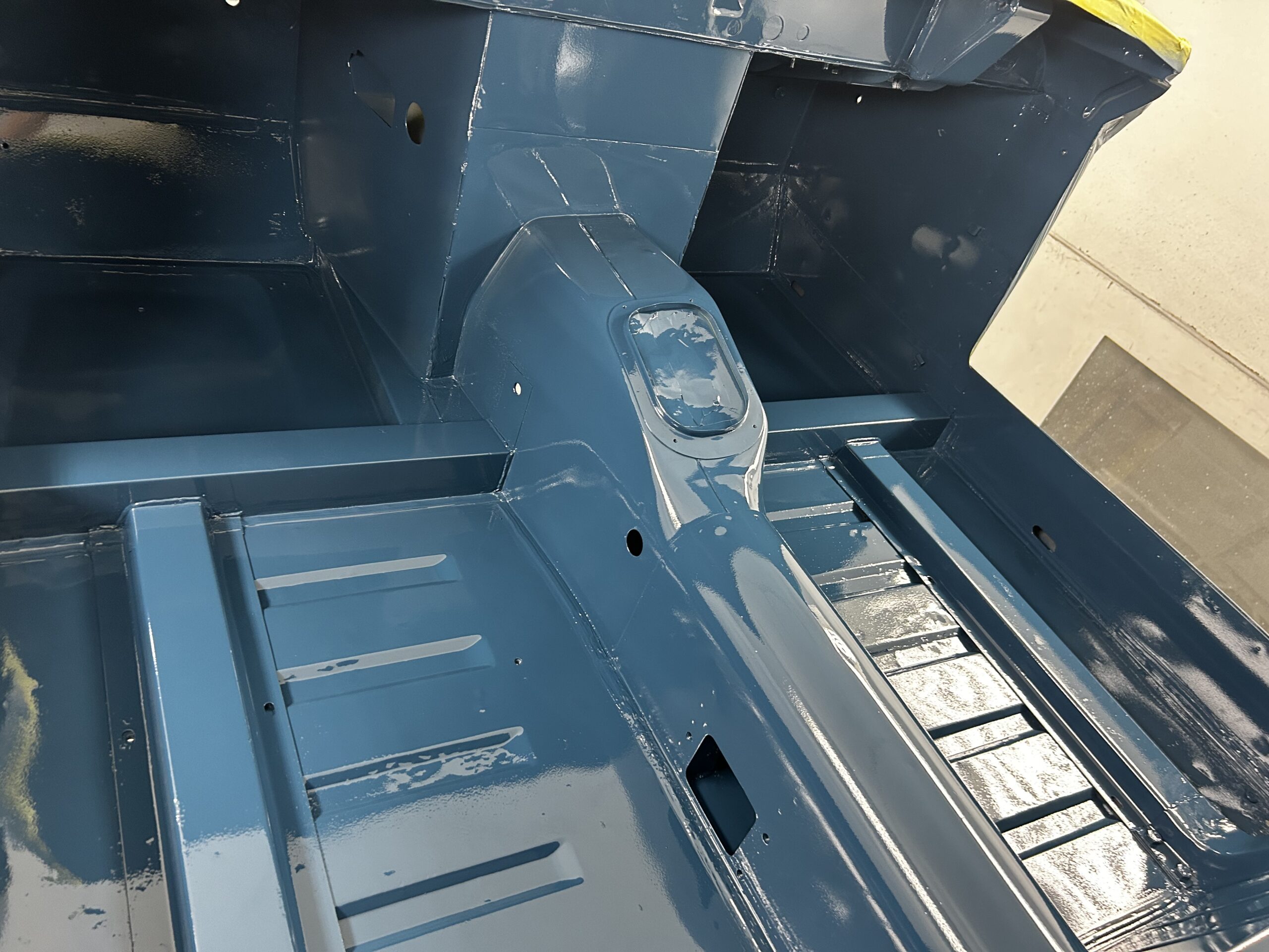
Front Interior 2
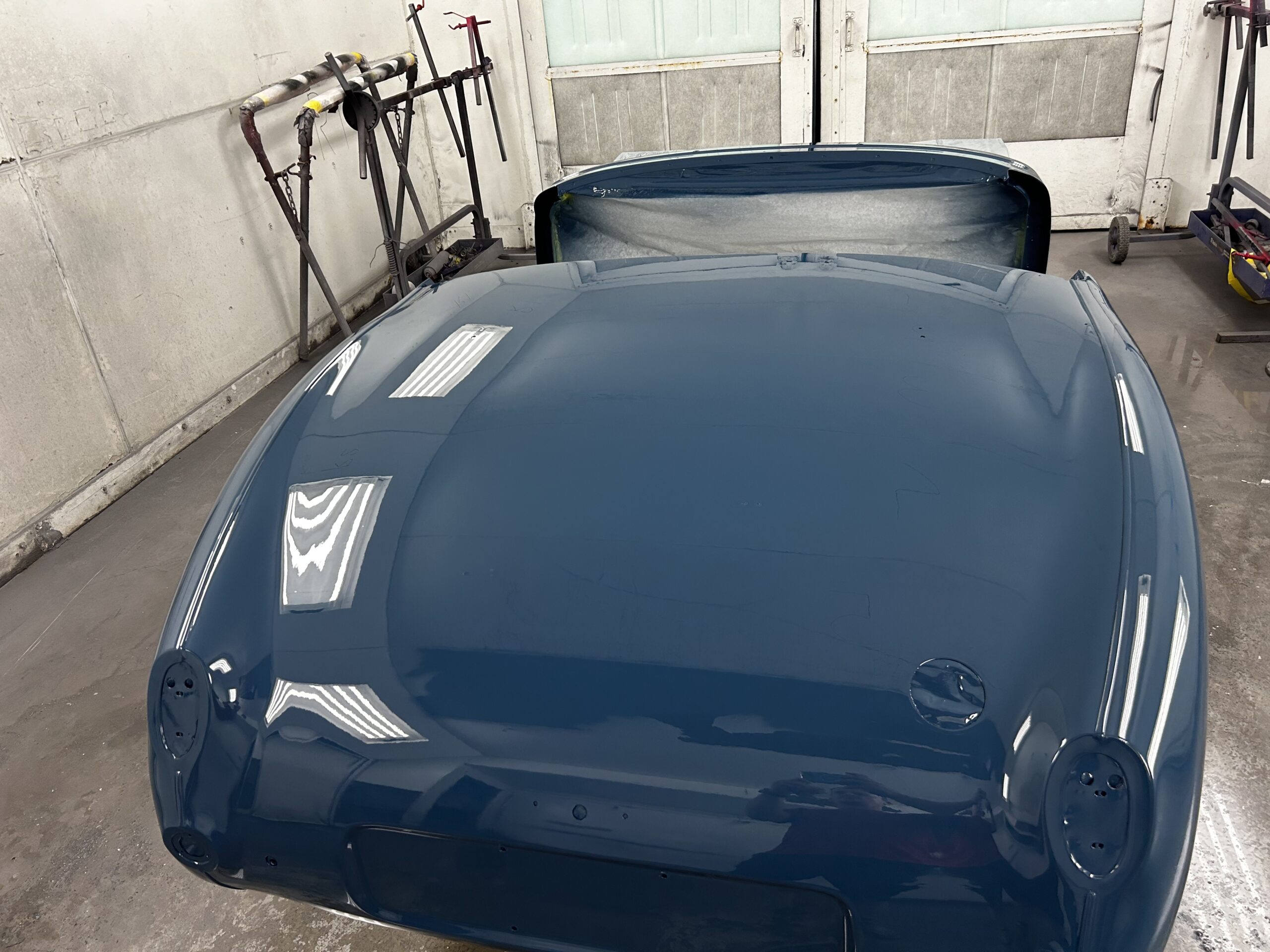
Exterior Sealer and Paint
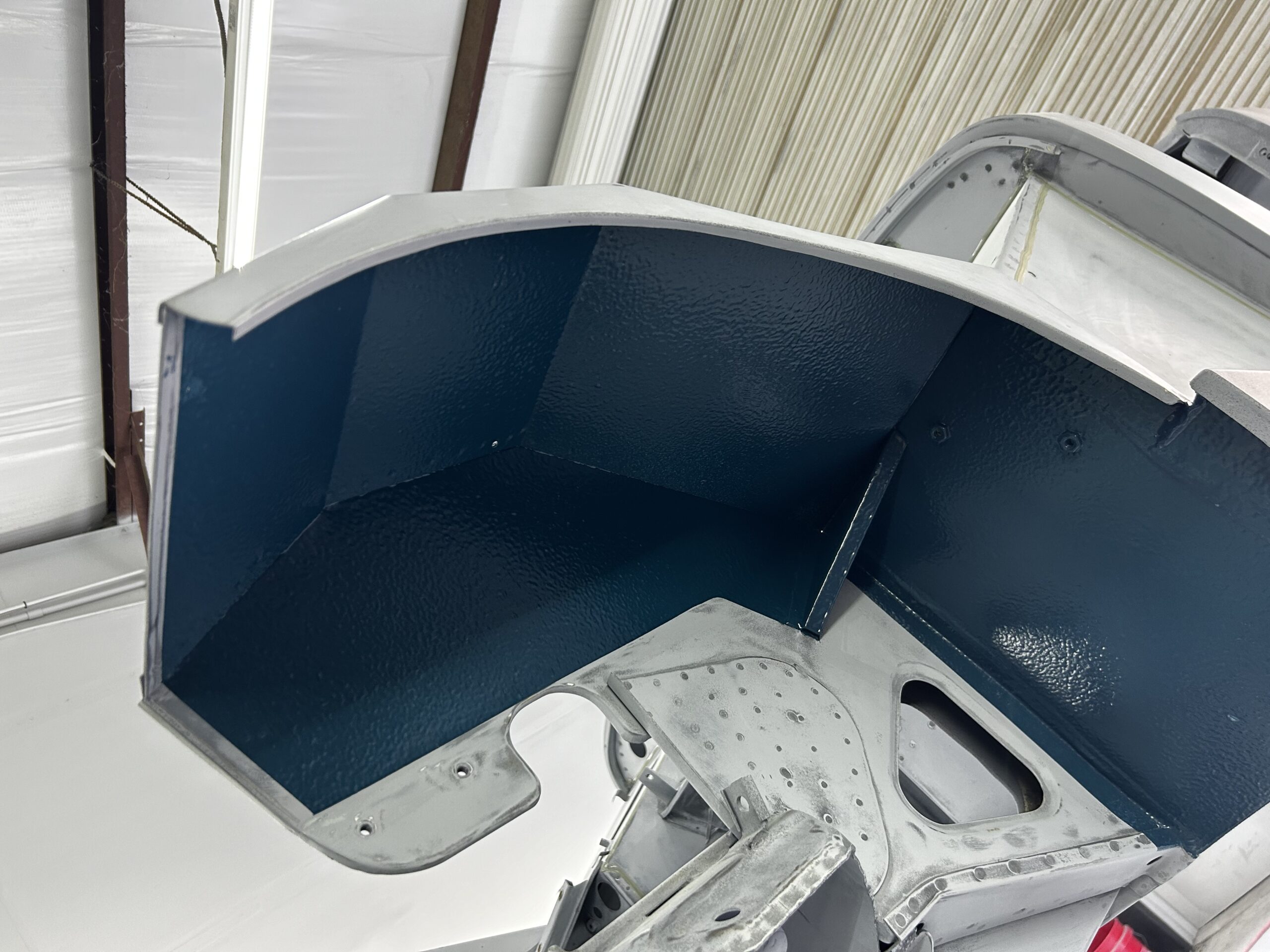
Two months to the day after taking the chassis/rear body to Gabor for final bodywork, prep and painting the car exterior received sealer, color and clear coat. The car will now cure for about a week and will then be sanded before two more coats of clear are applied.
Sealer before paint
Gabor with the Sealed Body
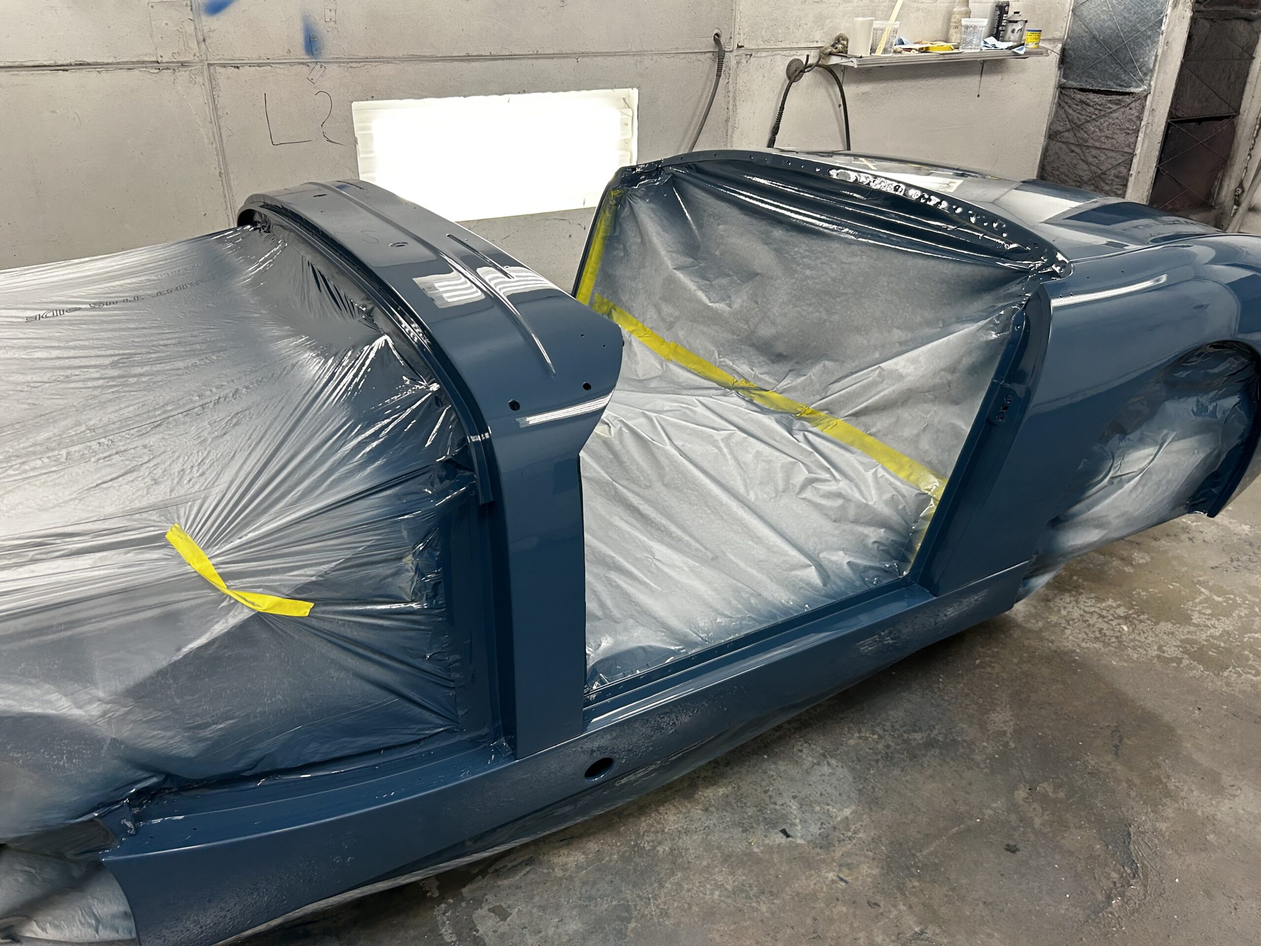
Body Paint 1 5-8-24
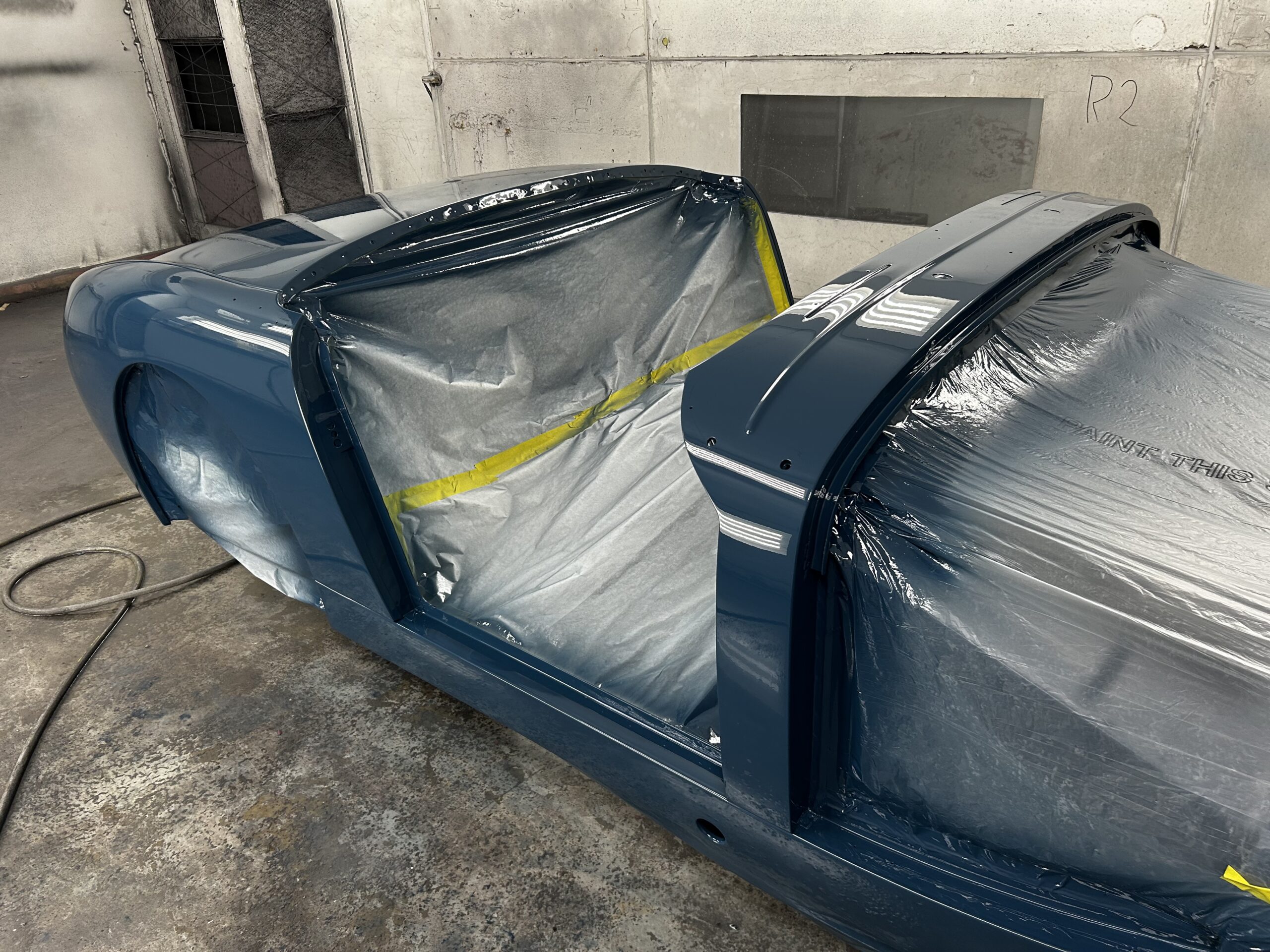
Body Paint 2 5-8-24
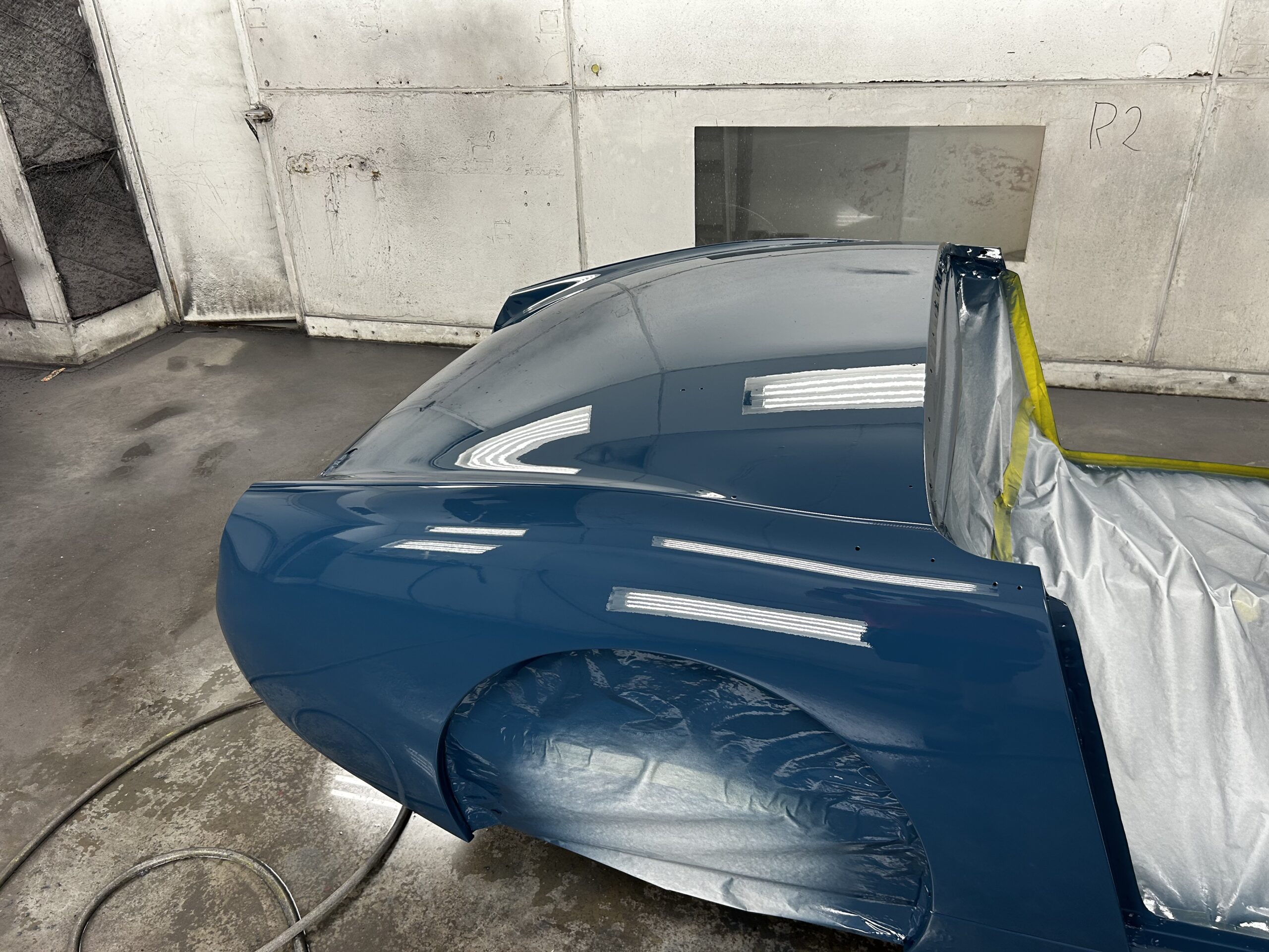
Body Paint 3 5-8-24
Body Paint 1 5-8-24
In the bright sun the Cotswold Blue paint looks so different!
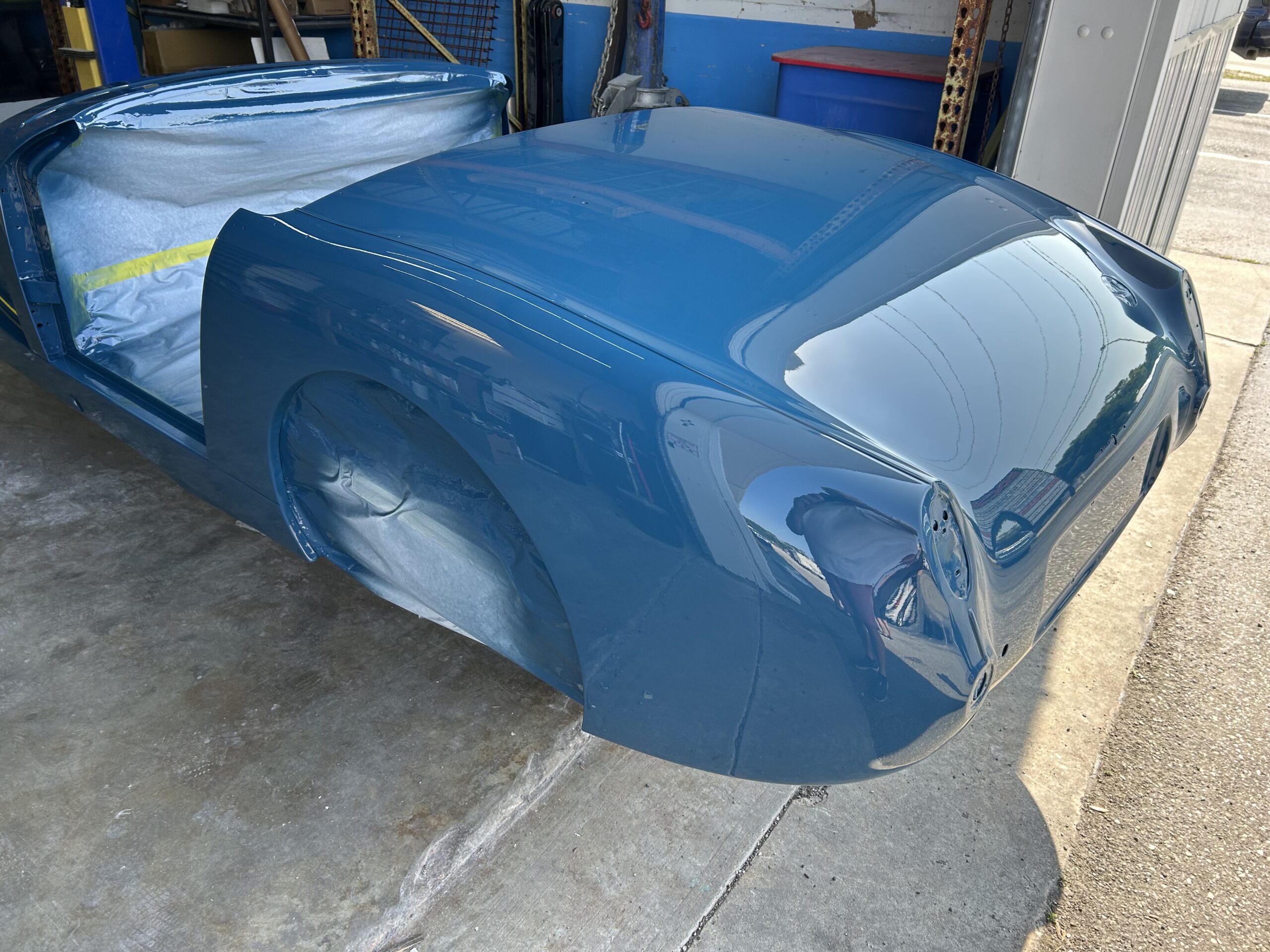
Cotswold Blue in the Sun
As the painting progresses more narrative and images will follow….