Handbrake Installation

We had previously refurbished the handbrake assembly. This was detailed 24:23 minutes into the Bugeye Restoration Video Episode Forty-two. https://vimeo.com/832369002/c87fd61c10?share=copy..  Further handbrake restoration was highlighted at the very beginning of Bugeye Restoration Video Episode Forty-fourhttps://vimeo.com/842617175/d7a040b143?share=copy

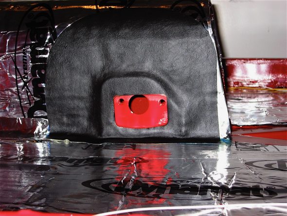
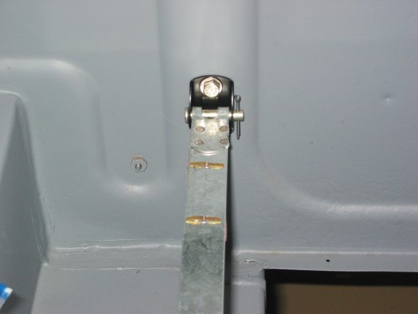
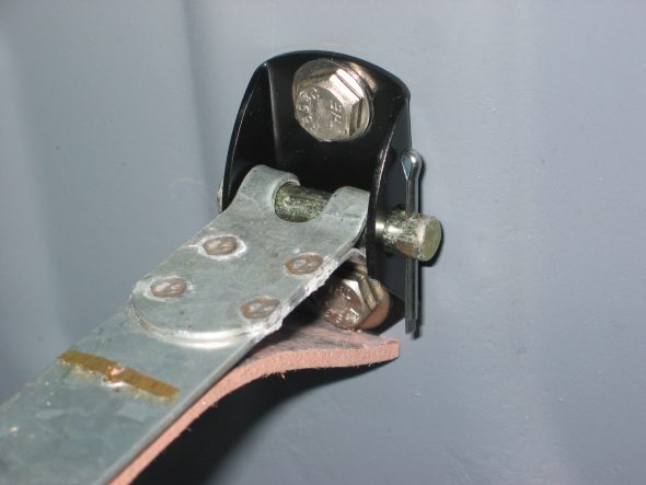
Before we could actually install the handbrake we applied Dynamat Extreme sound insulation to the propshaft tunnel and then glued aluminum duct insulation to the Dynamat Extreme for added heat insulation. We then glued some red vinyl to the area around the handbrake bracket.

Bugeye Restoration Video Episode Forty-eight shows the application of the insulation and the mountng of the handbrake assembly to the tunnel. Once the Rear axle is installed we will connect the handbrake cable to the brake cross rods. https://vimeo.com/986085408/43c579f77a?share=copy


The Bloody Beast “To-Do” List

Rear Disc Brakes

Caliper Modification

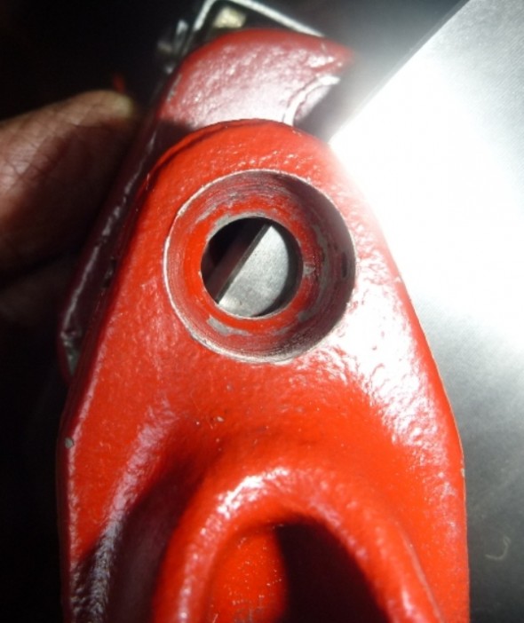
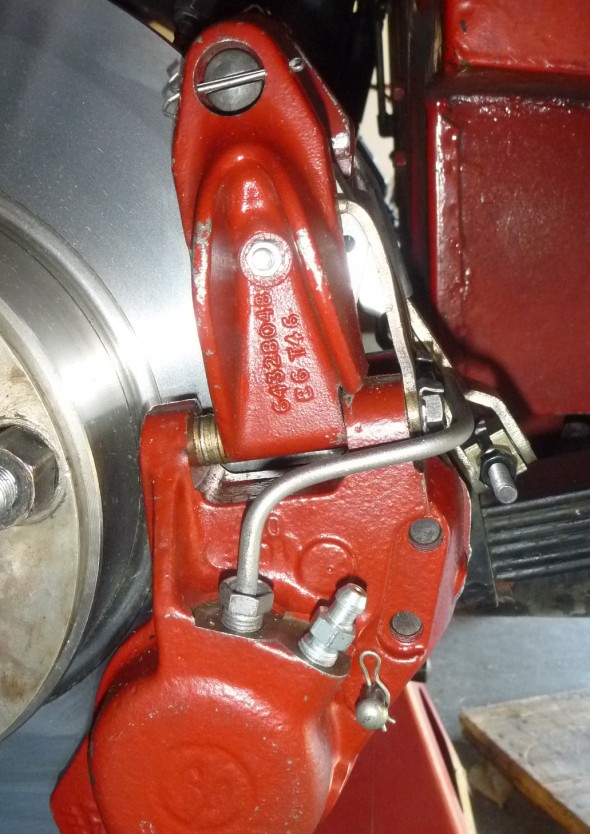
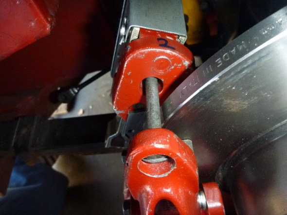
I have never been pleased with the fit of the rear brake rotors with the handbrake calipers. Steve Gerow ran into the same problem – the diameter of the rotor is about 1/4″ to great to fit the calipers properly. I like how he “fixed” the problem and when I have time I think I will take the same approach.

The Problem - Handbrake Needs to Be Modified

The Problem – Handbrake Needs to Be Modified

The fix - grind the housing back about .0275" and add washer stack

The fix – grind the housing back about .0275″ and add washer stack

Resolution

Resolution

Proportioning Valve

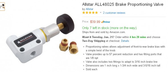
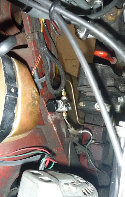
While I do not have a significant problem with the front/rear proportioning of the brakes after installing the rear disc system, some slight modification might yield a little improvement. Steve Gerow used a proportioning valve that provides the answer to optimal tuning. This is how he mounted his valve:

Proportioning Valve

Proportioning Valve


“Stock brake pipe wasn’t long enough; I cut and reflared it near the motor mount.

New line shown in photo was attached with a connector.”

“Adjustment – method was suggested with the car on jackstands:
to have an assistant lightly gradually apply the brakes while hand-turning a front and back wheel. Start with 7 turns on adjuster; adjust to the point where front brakes just locked and rears braking but still moveable.”

Valve Installed

Valve Installed


Ignition Modification


Steering Box Upgrade

At some point I would like to install new components form Denis/Welch. There is a question about standard versus high ratio.

Magnus Karlsson recommends the high ratio:

Go for the high ratio and tell your mechanic to look at my homepage. There you can see a modification I do in order to fit a modern and bigger oil seal to
the outgoing shaft of the steering  box. Makes it absolutely leak free and you
can use hypoid oil as intended.

Magnus Karlsson
www.healeyspecialists.com


Chapter 47 Restoration Assembly, Week Seventeen 4/9/2007

There wasn’t much time available for Healey work again this weekend. I did install some more Dynamat product over the interior floorboard and the propshaft tunnel. I was then able to glue the black interior vinyl around the handbrake bracket on the tunnel.

Handbrake vinyl

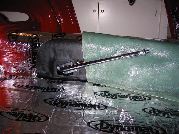
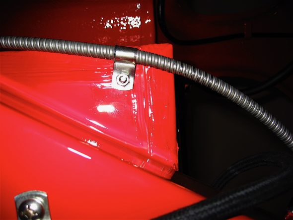
I then installed my rechromed handbrake lever and its mechanism including attaching the cable to the lever and to the bottom of the floor pan to keep it from fouling the propshaft.

Handbrake lever

Handbrake cable clip

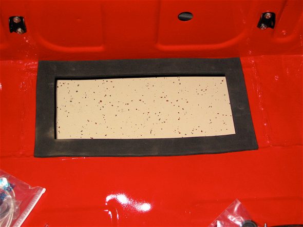
Using contact cement, I glued the foam rubber seal to the bottom of the boot in preparation for the fuel tank fitment.

Fuel Tank Seal

Chapter 17 – Cleaning and Trial Fitting

February 13 , 2004

Rear Disc Brake Conversion 

Decided to convert to disc brakes in the rear of the car and purchased the kit from Cape International. The kit consisted of two machined caliper mounting brackets, two Jaguar calipers including handbrake calipers, linkage for the handbrake, two disc rotors, templates for modifying the axle flanges and mounting hardware. The instructions provided assume the axle is on the car, but it appeared that the kit would be easier to install if the axle was removed from the car. I hope that the assembly can be inserted into the car from the right side once complete.  

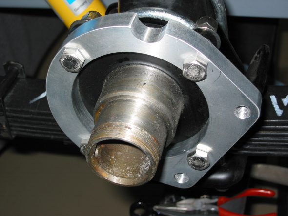
First modified the axle flanges using a dremel tool. The templates were used as a guide to mark the axle for cutting. The axle was repainted following the cutting. The caliper mounting brackets (not handed) were mounted to the axle flange using four 3/8” UNF bolts and nylock nuts.

rear caliper bracket 1

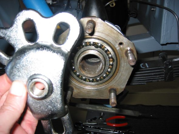
rear hub removal

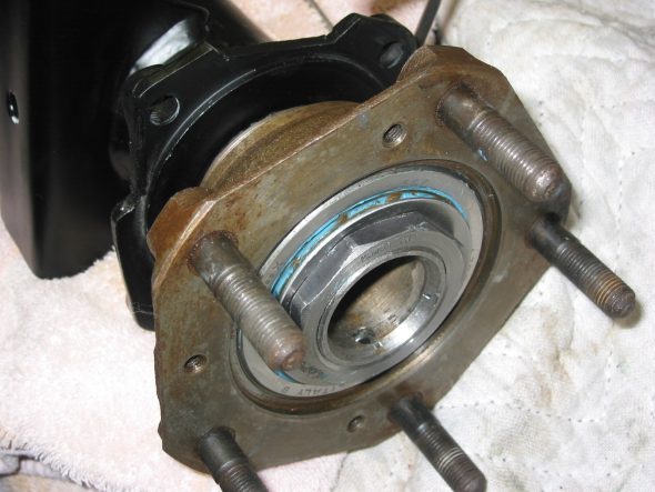
rear hub spacer,washer,nut

rear hub bearings

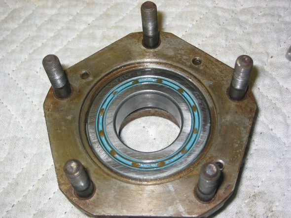
New rear bearings, and seals were pressed into the hubs. The bearing should protrude .001 to .004 from the surface of the hub after the outside washer and “O” ring seal are installed. Care must be taken to not drive the hub onto the axle too far or the bearing will be pushed too high. The tab washer and hub nut were then installed and tightened. The tab washer will not be bent down over the nut until absolute final assembly. The paper gasket was not affixed at this time since the half shafts will need to be pulled later for the installation of the differential. The half shafts were inserted and fastened to the hubs with one flat head tapered screw with a pozidrive head.

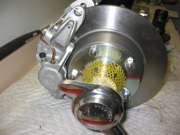
The new disc rotors were then attached with new hub extensions for the wire wheels. Care should be taken to put the proper hub extension on each side. Ten new conical lug nuts were provided in the kit. The calipers were then slotted over the disc rotors. 

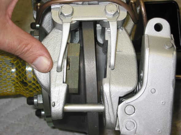
The first flaw in the Cape International kit was discovered at this point. The inside of the caliper rubbed against the rotor preventing free turning of the disc. A grinder was used to remove some material so prevent rubbing. It was then discovered that the outside of the disc also contacted the adjusting screw on handbrake caliper. The grinder was called to action again. Once these modifications were made, the caliper slotted over the caliper and mounted easily, aligning precisely over the mounting holes on the provided mounting brackets. Two 7/16”  UNF bolts were used for each caliper mounting. The bolt heads are drilled so that they may be “wired” to prevent loosening.

The calipers were painted Eastwood Silver wheel spray with a clear coat. The caliper units had a bronze anodized finish as delivered.

The second flaw in the kit was the lack of inclusion of the short brake lined used to connect the two sides of the same caliper. An email to Steve Norton resulted in the pipes being shipped right away. Once received the pipes were bent and installed without difficulty. The two brake pipes running along the axle were rebent to work with the new calipers.

rear caliper brake line

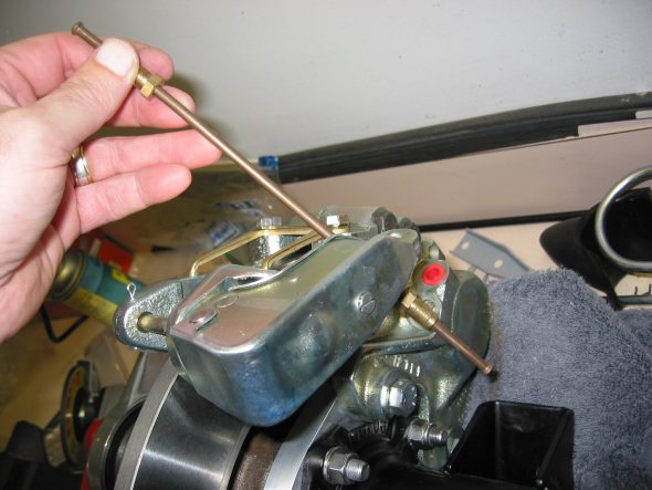
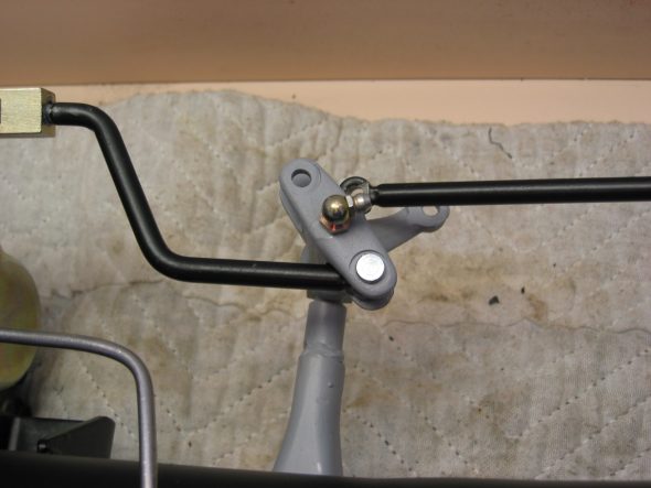
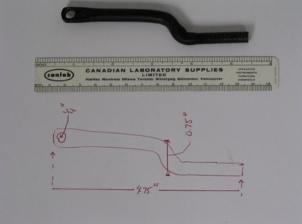
The third flaw was the discovery that the short rod provided for the link between the handbrake caliper on the right side of the car and the rotating handbrake lever did not come close to fitting. This is when I discovered quite by accident a web site created by Ed Driver in Canada. His web site contained a detailed explanation with photos of his installation of the Cape International disc conversion. He had run into the same difficulties and had fabricated a new short rod after receiving little satisfaction from Cape. He graciously sent me a photo and scale drawing of his new rod to use as a template for my application. Lifesaver!!

handbrake link rods 1

Disc Brake Custom Handbrake Connecting Rod

rear brake hub assembly

Handbrake caliper pad 4

March 24 , 2004

Return to Front Suspension Assembly

Shock Rebound – Installed the front shock rebound bushing on the shock tower.

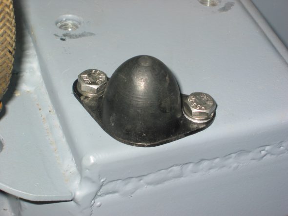
Front Shock Rebound buffer

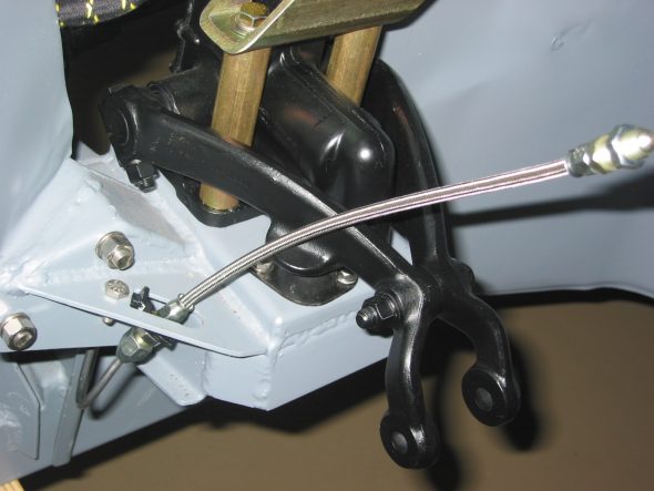
Caliper Brake Lines – Installed new stainless steel brake lines to the front calipers ordered from Cape International.

Stainless Brake hoses

Fresh Air Intake Clip – Installed the clip for the air hose to the front wheel arch.

Air hose wheelwell clip

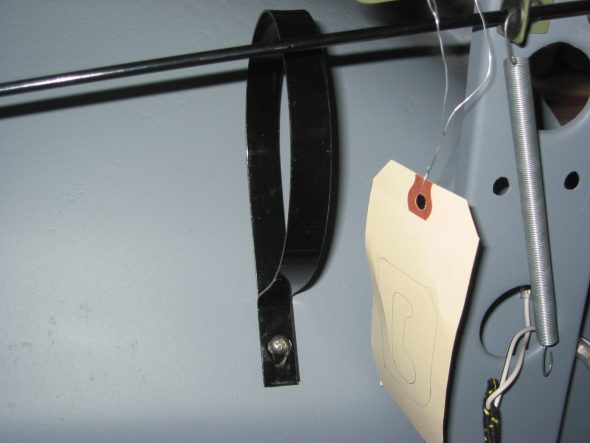
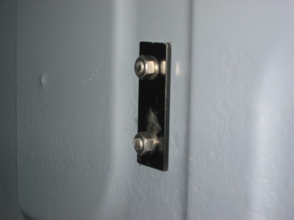
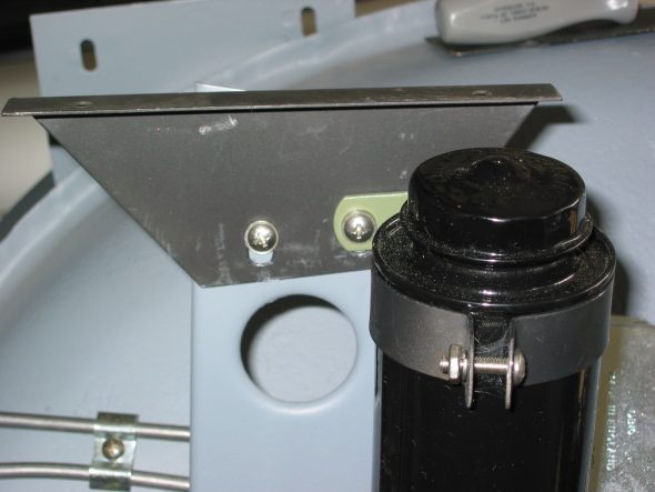
Fuel Tank Straps – Installed the two fuel tanks strap brackets to the rear boot panel. Each bracket has a backing plate on the other side of the boot panel. Note that the bracket curve Is on the top of the bracket.

Fuel tank strap bracket 4

Fuel tank strap bracket 3

Fuel tank strap bracket 2

March 24 , 2004

Cooling 

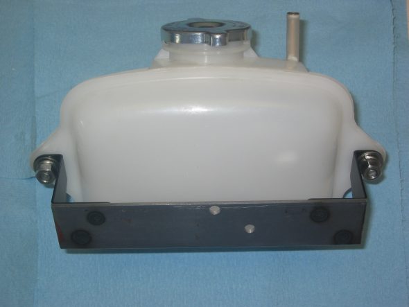
Cooling Recovery Tank – Began the installation of the radiator expansion tank from Cape International. However, I decided to wait to determine the final location until after the motor is installed. I don’t want to inhibit access to distributor or oil filter.

Coolant Recovery Tank with custom Bracket

Brakes 

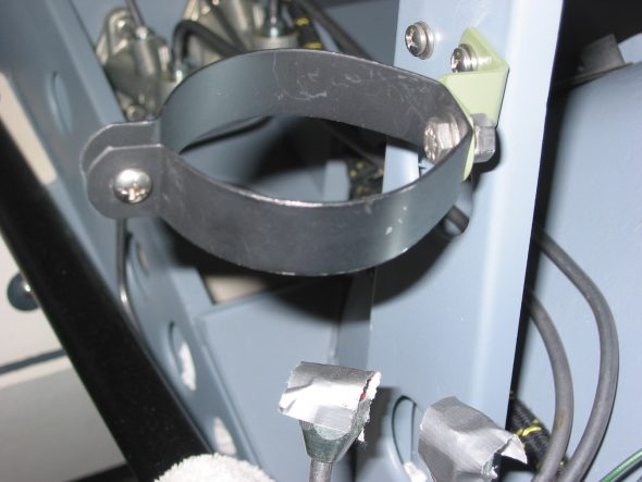
Brake Fluid Reservoir – Installed new brake fluid reservoir and will need to put thread sealer on fittings for final assembly.

Brake reservoir clip 2

Brake Reservoir Mounted

April 17 , 2004

Handbrake Restoration 

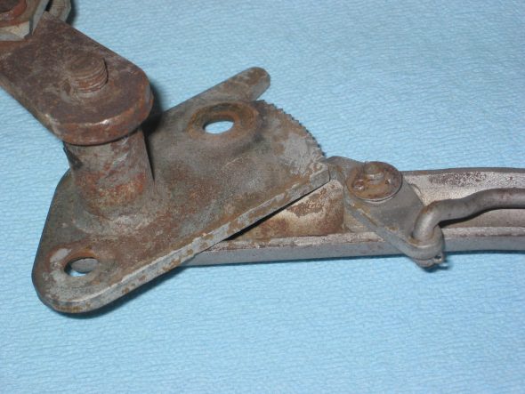
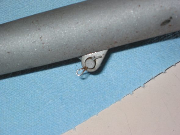
I decided to restore the original handbrake rather than purchasing a new one. This will require rechroming several pieces. Removed small split pin securing the rod to the lever. Then removed the small split pin and washer from the lever holding the pawl.

Handbrake Assembly 1

Handbrake Pawl split pin

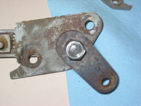
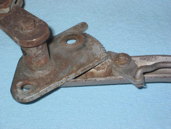
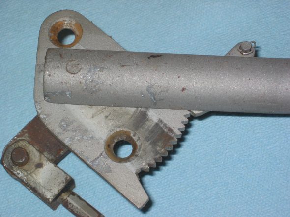
Disconnected the rod from the pawl and lifted the pawl off. Removed bracket with a hole and a rectangular opening for a key by heating with a torch and knocking out the piece. (Note orientation for reassembly). Hammered ratchet plate off of the mounting shaft to handle. There is a thin shim washer on the handle post before the ratchet plate is inserted on the shaft. The handle, pawl and ratchet plate will be chromed. The bracket and two spacers were painted black.

Handbrake connecting plate

Handbrake Assembly 1 2

Handbrake Assembly 2

Brakes MK2

The Front and Rear Brakes

The Jaguar MK2 uses a single line hydraulic system actuating disc brakes in both the front and rear of the car. While the four wheel disc brakes were “cutting edge” at the time of production for a four-door sedan, today, the braking action can be upgraded with vendor supplied modification kits. Front Brake Upgrade I decided to go with the Coopercraftbrake upgrade kit for the front and rear of the car. Up front, their four pot brake caliper range has been updated to include stainless steel pistons, a refined and improved caliper design for strength and efficiency. To gain some weight savings I installed the optional aluminum calipers. The system employs ventilated disc rotors that should help with cooling. No modifications were required for mounting. Every thing was a “bolt-on” application. Coopercraft provided fitting instructions with their kit:
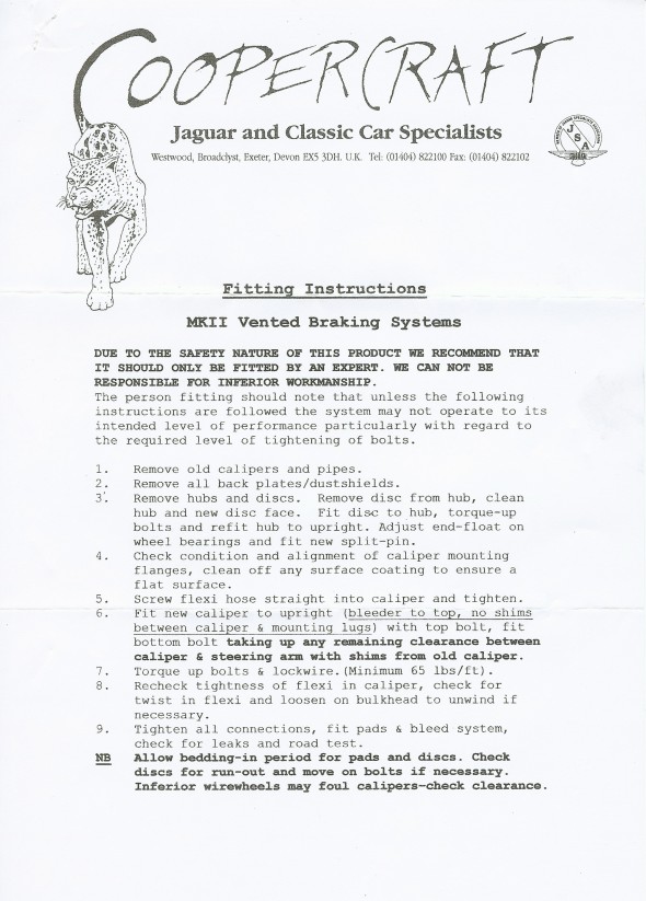
Coopercraft Front Braking Installation Instructions
Coopercraft Front Braking Installation Instructions

Calipers and Pads
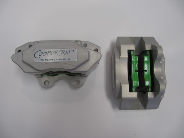
Calipers and Pads

Coopercraft Calipers

Coopercraft Calipers

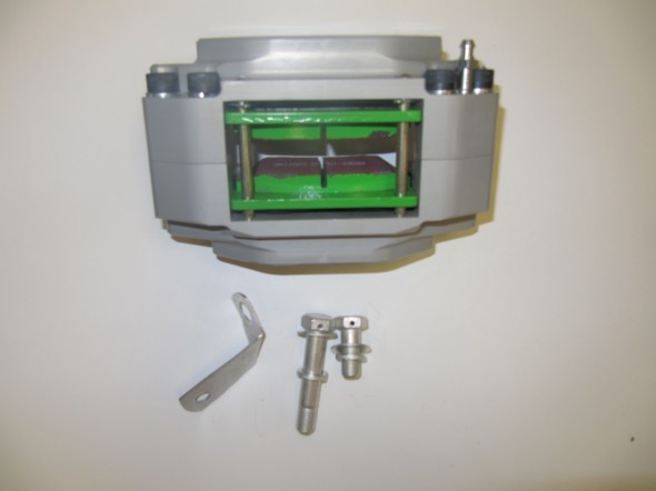
The photos above show the upgraded EBC “Green Stuff” brake pads. After installing the vented rotors on the front suspension crossmember assembly I installed the calipers finding that it appeared that no shims would be needed for proper fit.  Two bolts secure each caliper to the stub axle housing lugs: The shorter 1/2″ x 1 1/8″ – 20 is at the upper mount and the longer 1/2″ x 2 5/8″ – 20 is at the lower mount. Each bolt is accompanied by a flat washer and a split washer. The cad plated brackets were used on the original brakes to support the union of the rubber brake hose to the metal caliper pipe. With the Coopercraft upgrade these are not used, as the hose links directly to the caliper.

However, I found that sliding the EBC pads into the caliper, on either side of the rotor, was difficult and the concluding fit was much tighter than I liked. After checking with Coopercraft, they advised that the EBC pads are about 2mm wider than the standard pads. I volunteered that while I was looking for an “upgraded” braking experience, I was not going to be racing the car. They suggested that I might want to go with standard pads rather than the EBC pads. They also recommended that if I was going with standard pads in the front brakes that I should do the same with the rear brakes. Oh well, just wasted money once again!

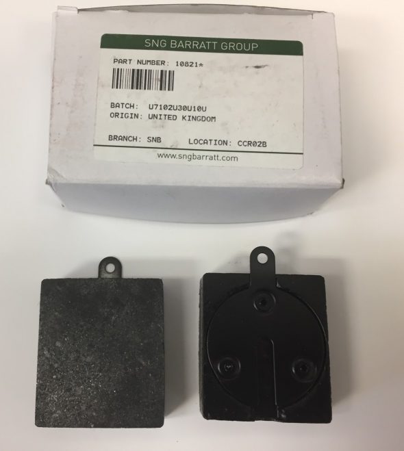
I ordered standard front pads to fit a Series II/III E-Type (the proper pad to fit the upgraded alloy calipers) JLM 9515 as well as standard pads for the rear 10821* from SNG Barratt and they fit just as they should. Wish that I had ordered the Mintex pads to begin with!
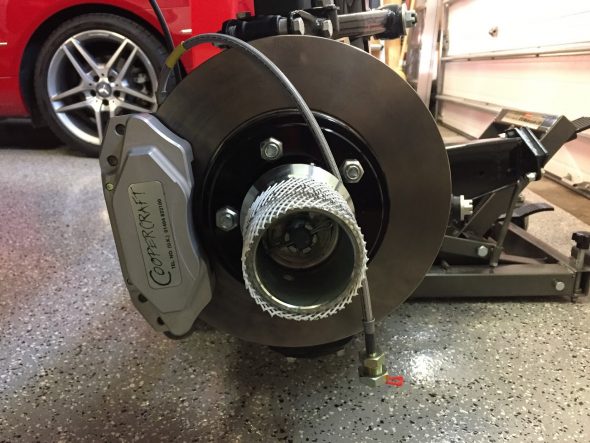
Coopercraft Vented Rotors, Alloy Calipers fitted with Goodridge Stainless Brake Hose and Hubs installed
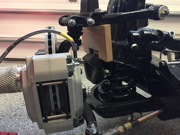
Coopercraft Vented Rotors and Alloy Calipers with Standard Mintex Pads and Hubs Installed

Anti-rattle clips are added after the pads and pins are installed. These spring clips are part number 12292 and a total of four are required.
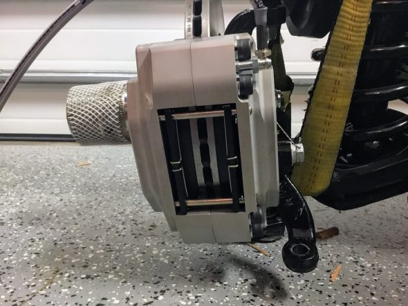
Anti-Rattle Spring Clips for Brake Pads Installed
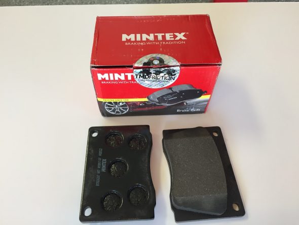
Mintex Front Caliper Brake Pads


I replaced the original rubber brake hose with Goodridge stainless hoses. The larger fitting on the end of the hose is metric, 16 mm diameter – .50 with with a 16mm -.50 nut.
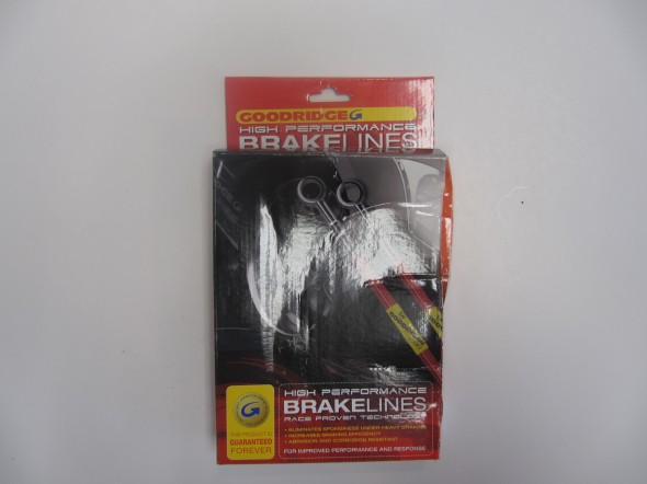
Goodridge Stainless Brake Hose

Goodridge Stainless Brake Hose

After mounting the calipers I safety wired the caliper mounting bolts. 
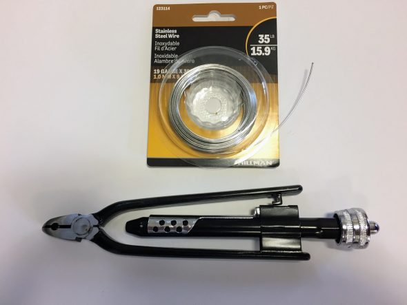
Stainless Safety Wire and Twist Tool

I used 19 gauge wire that is probably a little heavier than needed but it worked just fine. If you are doing safety wiring, it can certainly be done with regular pliers, but the twist tool gives a very nice uniform appearance to the wire and is easy to use. 
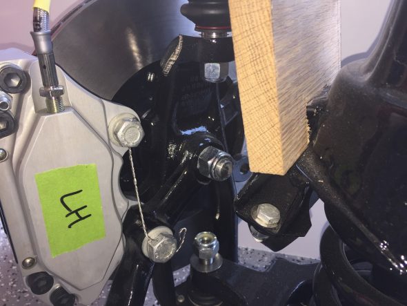
Safety Wire on Front Brake Calipers

No videos are perfect, but this short video gives you a pretty good look at how safety wiring should be done. There is sound but screen captions are used initially.

Rear Brake Upgrade

In the rear, the Coopercraft upgrade kit consists of four redesigned and uprated cylinders, incorporating stainless steel pistons in an alloy caliper. This kit utilizes the standard handbrake mechanism and is designed to maintain a good balance with their uprated front sets. As stated previously, I did not use the EBC pads and instead substituted the standard pad provided by SNG Barratt.
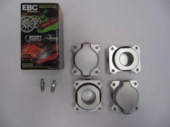
Alloy Rear Brakes
Alloy Rear Brakes

Rear Brake Friction Pads

The small tabs with holes in each brake pad is to permit the insertion of a hooked wire to pull the pad out when it is replaced. The pads are held in place by the Retaining Plate for Friction Pads as seen below with mounting hardware.
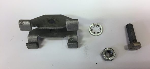
Rear Brake Friction Pad Retainer with Fasteners

The image below shows the Coopercraft Alloy Pistons and Housings installed in the original calipers with new pads secured by the pad retainer. 
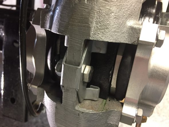
RH Rear Brake Caliper with Retaining Plate for Friction Pads Installed

The calipers need to be centered around the rotors and this is accomplished with the use of shims on the two bolts securing the calipers to the axle. On my car, I use five .010″ shims on the upper bolt of the RH caliper and five .010″ shims on the lower bolt. On the LH side, I used no shims on the upper bolt and two .010″ shims on the lower bolt.

Following assembly, I safety wired the mounting bolts for both rear calipers.
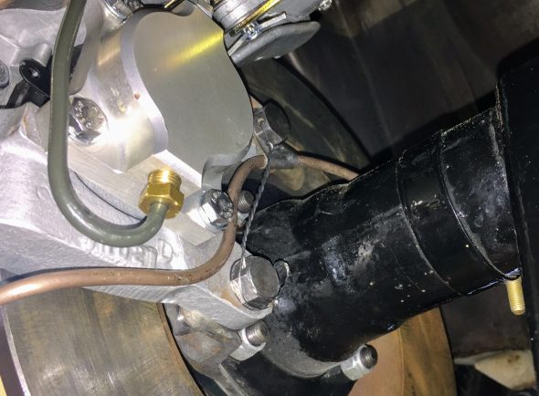
Safety Wired Rear Calipers

A warranty is also provided by Coopercraft:
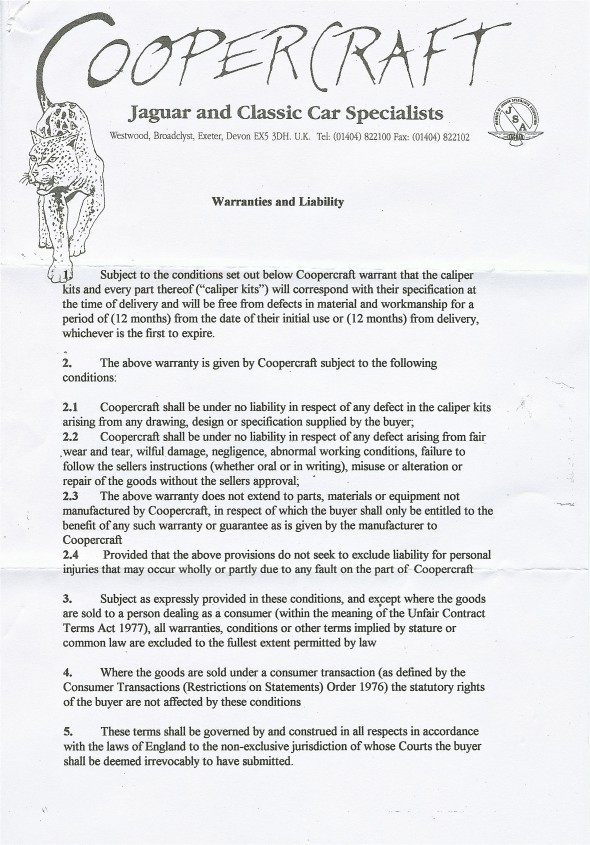
Coopercraft Brake System Warranty and Liability

Coopercraft Brake System Warranty and Liability

Rear Brake Caliper Rebuild
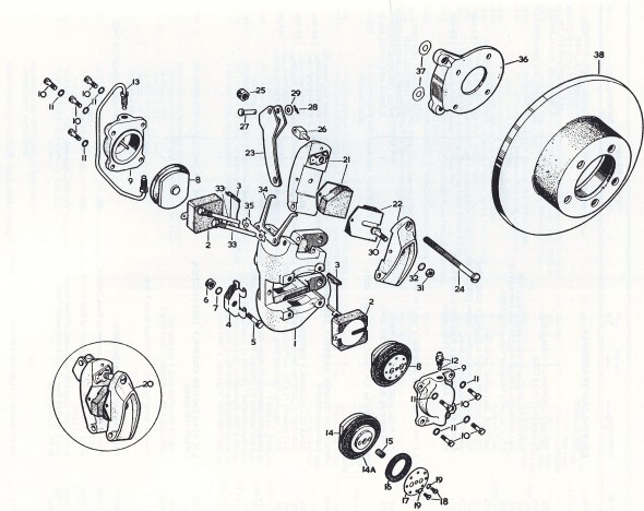
Rear Brakes

Rear Brakes

In addition to adding the new Coopercraft Piston/Cylinder Sub-Assemblies I completely rebuilt the Rear Caliper Assemblies including the Handbrake Calipers. As the image below illustrates the original silver color was long gone!
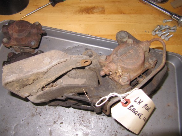
Left Rear Brake Caliper

Left Rear Brake Caliper

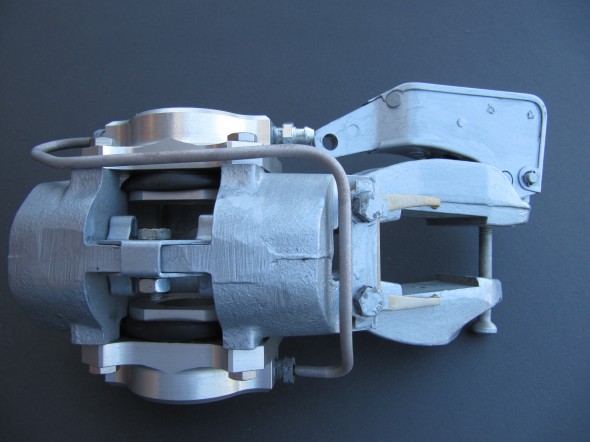
To disassemble the calipers, I first separated the handbrake calipers from the primary caliper. To do so, I bent back the tabs on the Tab Washer and unscrewed the two Bolts, Securing Handbrake Mechanism to Rear Calipers. I then removed the Retraction Plate Fork that permitted the removal of the LH and RH Handbrake Pad Carrier Assembly with the friction pads. The Bolt, Securing Pad Carriers to Operating Lever was then unscrewed separating the two Carriers. I then removed the Support Plates for friction pads which simply fit into slots on the caliper body. Four 1/4″-24 x 7/8″ hex head bolts with shakeproof washers secured each Piston/Cylinder Assemblies. These were removed and the assemblies with the friction pads were removed. The Retaining Plate for friction pads was held in place with a 1/4″ – 24 x 7/8″ hex head bolt. It was removed and will not be replaced until the caliper is mounted and the new friction pads are installed. The Bridge Pipe Assembly and the Bleed Screw and Ball Assembly were removed from the Piston/Cylinder Assemblies and replaced with a new pipe and fittings. All components were then media blasted or otherwise cleaned and painted with Eastwood’s silver ceramic caliper paint. New bolts and screws were installed along with new friction pads.
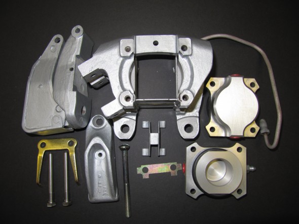
LH Rear Brake Caliper Components
LH Rear Brake Caliper Components

Right Rear Brake Caliper Refurbished
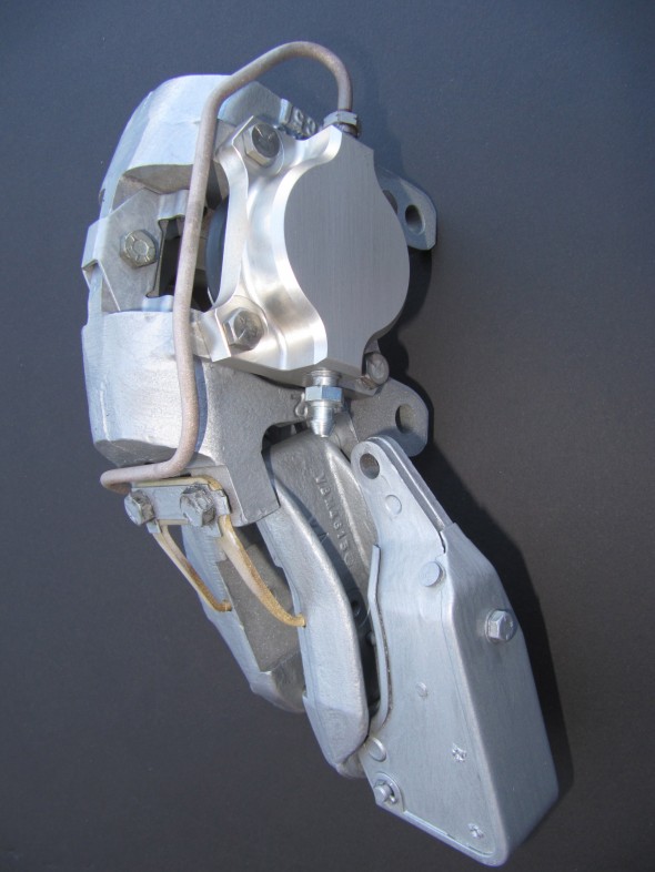
Right Rear Brake Caliper Refurbished
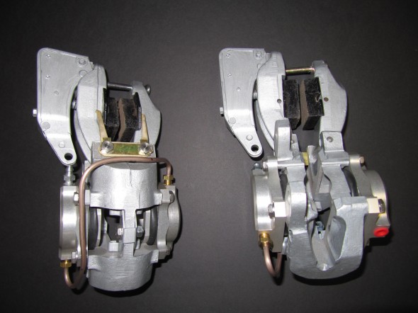
Right Rear Brake Caliper Refurbished

Right Rear Brake Caliper Refurbished

Rear Caliper LH & RH

Rear Caliper LH & RH


zz