Front Disc Brake Conversion

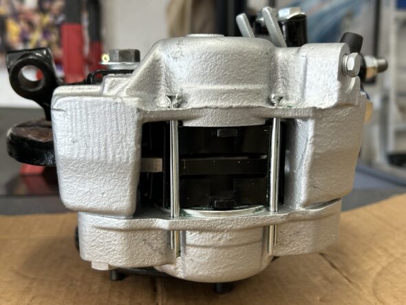
We bought the Bugeye in 1998 and shortly thereafter the car was taken to Grand Touring Classics, Inc in Stanarsville, VA for a safety inspection and a conversion to front disc brakes. Garland Gentry and his assistant took care of collecting the needed parts from a post 1964 Midget and installing them on the car. After some period of time we changed out the 7/8″ master cylinder for a 3/4″ which worked much better.

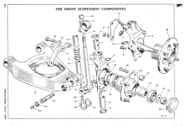
Of course, it is not as simple as just switching out the brakes. it is also necessary to install new stub axles and king pins, dust tubes and springs, hubs, back plates, calipers, hose brackets, rotors, pads with pad retaining plates with clips, new hoses with banjo bolts and copper washers. For the complete restoration of the car in 2024 all of the front brake components were updated and/or replaced. Parts were sourced from A.H. Spares and Moss Motors.

The front brakes, steering and suspension are integrated in assembly. Details of all of these  mechanicals are detailed in other posts regarding these subjects. The build up of the front hub assemblies and brakes ,may be found in this post: https://valvechatter.com/?p=13792   A video showing the assembly is included in the post.

Front Suspension, Brakes and Steering Completed

It has been a little more than three months since we began the work on the front suspension, brakes and steering in the Bugeye, but we have now completed the rebuild and have the car back on its tires and on the ground!

Everything has been updated and documented in previous posts in this blog:

New hub bearings and seals

New king pins and bushings in the spindle axles

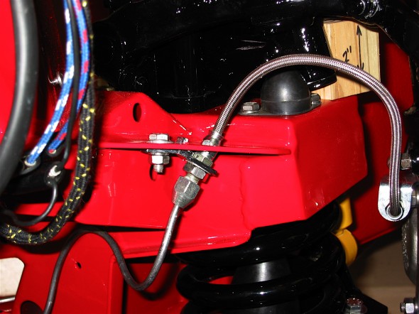
New rotors, calipers and brake pads, new Goodridge stainless brake hoses, new cunifer hard brake pipes, new “Sebring-type” pedal box and pedal pads with separate master cylinders

New “A” arms, fulcrum pins and poly bushes throughout

New steering rack, shims and rod ends and the proper steering arms were sourced and installed

Rebuilt lever shocks and new rubber bump stops

New coil springs

Everything cleaned and painted

The Bugeye Restoration Episode Thirty-five video shows the final steps in completing the work described above. 

https://vimeo.com/810655660/46123c8339

The following steps are addressed in the video:

0:00 – Torquing the hub nuts and installing split pins

0:44 – Hub grease caps installed

0:48 – Front caliper banjo bolts installed

1:20 – Goodridge Stainless Steel flexible brake hoses installed

1:35 – Making brake pipe bubble flares

4:42 – Master cylinder to brake union brake pipe installed

5:00 – Steering rack installed

5:52 – Steering rack bracket shims installed

6:14 – Steering column to steering rack pinion shaft mating

6:50 – Steering rack mounting clamp bolts torqued

7:17 – Tie rod ends fitted and torqued

7:30 – Toe-in adjustment

7:50 – Front tires mounted and car placed back on the ground

9:12 – Inner fulcrum pins tightened


Front Hub Assemblies and Brakes

Continuing with the front suspension rebuild, we assembled the swivel pins (stub axles) to the hubs and brake rotors. New king pins were installed in the axles after new bushings were fitted and reamed. New grease zerks were fit and poly bushes were installed in the upper trunnion.

Front Suspension
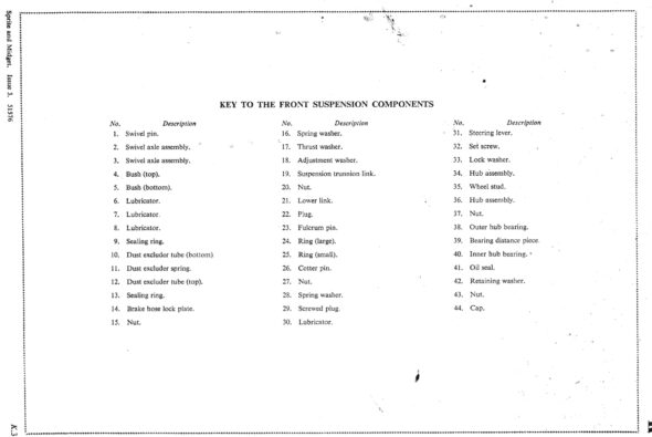
Front suspension Components

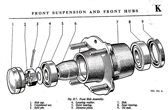
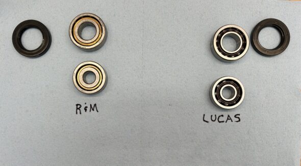
We did a fair amount of research regarding the proper ball bearings to use for the Sprite/Midget front suspension. Bearings from the usual British parts suppliers don’t seem to completely replicate the original bearings used as manufactured. A British supplier, Ransome and Marles, https://www.ransomeandmarles.co.uk does sell the original ball bearings. They are pricey, but in this case the quality and value seem worth the price. Proper fit and tight tolerances are important! The bearings came with a new oil seal as well. We packed the bearings with high quality bearing grease and installed them in the hubs and then installed the oil seals.

Front Hub assembly
R&M Bearings and Lucas Bearings Comparison

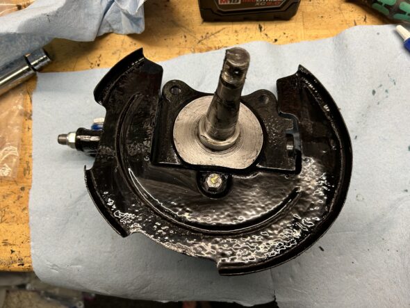
We then secured the new brake rotors to the hubs with the original four bolts and torqued each to 40 ft. lbs. The brake dust shields must be attached to the swivel axles with the one hex bolt before the hub and rotor are slipped onto the swivel axle.

Dust Shields Installed

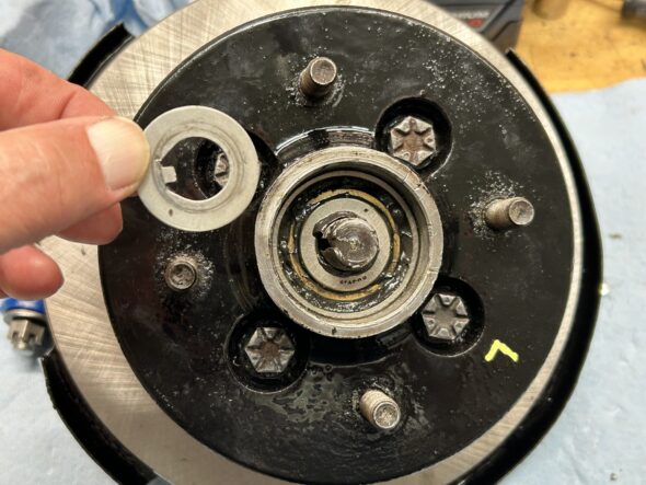
Once the hub and rotor and the swivel axle are mated the tab washer can be installed on the axle followed by the castle nut. The nut is then torqued to 46 ft. lbs and then rotated clockwise until the hole in the axle lines up with an opening in the castle nut. A cotter pin can then be inserted and bent back although we will wait to bend the pin until the hub assemblies are actually on the car.

Tab washer on stub axle
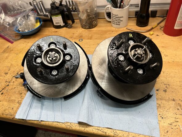
Hub Assemblies


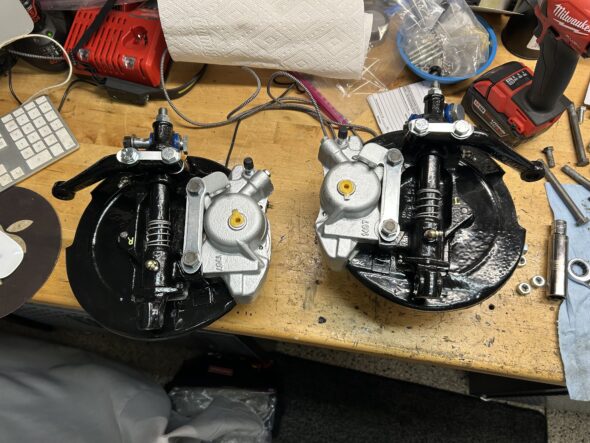
The new brake calipers sourced from Moss Motors were then installed on the hub assembly. As the accompanying video shows, the two 7/16″ bolts that secure the calipers to the assembly pass through the locking tab washer, the brake hose locating bracket, the dust shield, the caliper and then into the swivel axle. These bolts are torqued to 50 ft. lbs. Again, we will wait to bend back the tab washer until the hub assemblies are on the car.

The proper steering arms were then fastened to the hub assembly along with a tab washer that will be bent back later.

Calipers Installed on Hub assemblies

Classic Gold brake pads purchased from Moss Motors were installed into the calipers along with shims. The shims were coated with a Permatex lubricant designed for this purpose. The pads are extremely tight against the rotor. We tried releasing the bleeder valve and pushing back the pistons but this did not rectify the problem.

Brake caliper with classic gold pads

Some EBC green pads were ordered to see if they might fit better. 

The Episode 32 video shows the process of the hub and brake assembly: https://vimeo.com/797978369/33c374192a

0:00 – New king pins in swivel axles

0:25 – Axle grease zerks and poly bushes in the upper trunnion

1:10 – Ransome and Marles ball bearings on axle

2:10 – Bearings installation

2:43 – Packing bearings with grease

4:20 – Tapping bearings into the hub and installing the spacer

6:50 – Install oil seals in hub

7:05 – Brake rotors fastened to the hub

7:40 – Dust shield installation

8:20 – Tab washer installation on axle shaft

8:42 – Castle nut on axle shaft torqued to 46 ft. lbs.

9:10 – Brake calipers, brake hose brackets, tab washers installed

11:10 – Steering arms with tab washers installed

11:40 – Classic Gold brake pads and shims installed


Brakes

The front drum brakes of the 100-Sixes were replaced by Girling 11” disc brakes on the 3000 in March 1959. Rear brakes were 11” Girling drums that were also controlled by a handbrake lever located on the right side of the gearbox tunnel

 Brake Modifications

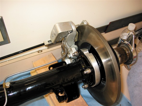
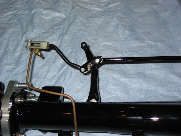
The most significant modification I made to the braking of the 1960 MKI was the conversion of the rear drum brakes to disc brakes. This was accomplished with a kit based on Jaguar calipers coupled with mini-handbrake calipers sourced from Cape International. New rods to connect to the balance lever are supplied so that the handbrake functions as original. This is a pdf file of the instructions provided by Cape International.Cape Int Disc Brake Conversion 1

Rear Disc Brake

Rear Disc Brake

Handbrake Lever

Handbrake Lever

Aeroquip Braided Stainless Steel Hoses

Original-style rubber brakes hoses were replaced with stainless braided hoses also sourced from Cape International.

Stainless & Braided Brake Lines

Stainless & Braided Brake Lines

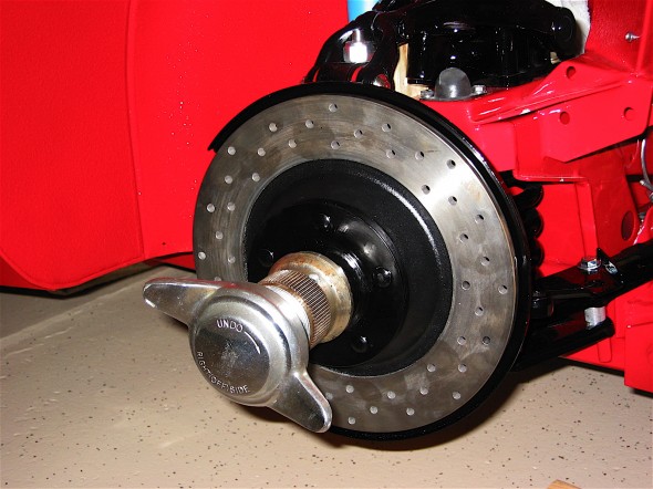
Drilled Front Brake Rotors

While standard rebuilt calipers were used in the front, the rotors were replaced with drilled rotors supplied by Cape International.

Drilled Front Rotors

Drilled Front Rotors

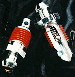
Speed Bleeders

I utilized the new technology for brake bleeders, Speed Bleeders. These bleeders have a small stainless ball in them that close off the release of brake fluid, making the process of brake bleeding much easier.

Speed Bleeders

Speed Bleeders

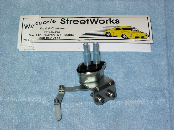
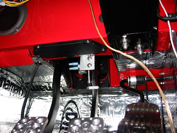
Recent production of the hydraulic brake switch has not produced a reliable switch. A remedy to the situation is to use a mechanical brake switch first developed by hot rodders. I sourced the switch I used from Watson’s Street Works. A description is provided in this Watsons mechanical brake switch.

Watson's Brake Switch

Watson’s Brake Switch

Watson's Brake Switch

Watson’s Brake Switch

 Brake Reservoir Canister Gasket

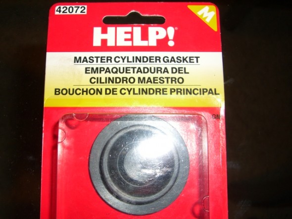
Other Healey restorers had noted that if overfilled, hydraulic fluid could slosh out of the vent hole in the reservoir cap and ruin the paint. Ever resourceful contributors to the British Car Forum discovered that a simple little gasket available in most auto parts stores fit perfectly in the reservoir cap, thereby solving the problem. I used one of the se “HELP” gaskets, #42072 in the Bloody Beast.

HELP Gasket

HELP Gasket

zz

Brakes MK2

The Front and Rear Brakes

The Jaguar MK2 uses a single line hydraulic system actuating disc brakes in both the front and rear of the car. While the four wheel disc brakes were “cutting edge” at the time of production for a four-door sedan, today, the braking action can be upgraded with vendor supplied modification kits. Front Brake Upgrade I decided to go with the Coopercraftbrake upgrade kit for the front and rear of the car. Up front, their four pot brake caliper range has been updated to include stainless steel pistons, a refined and improved caliper design for strength and efficiency. To gain some weight savings I installed the optional aluminum calipers. The system employs ventilated disc rotors that should help with cooling. No modifications were required for mounting. Every thing was a “bolt-on” application. Coopercraft provided fitting instructions with their kit:
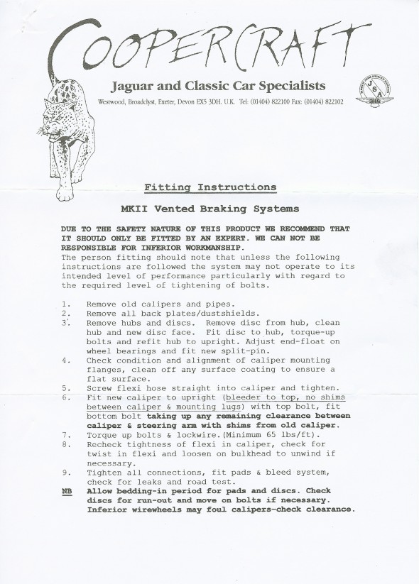
Coopercraft Front Braking Installation Instructions
Coopercraft Front Braking Installation Instructions

Calipers and Pads
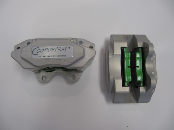
Calipers and Pads

Coopercraft Calipers

Coopercraft Calipers

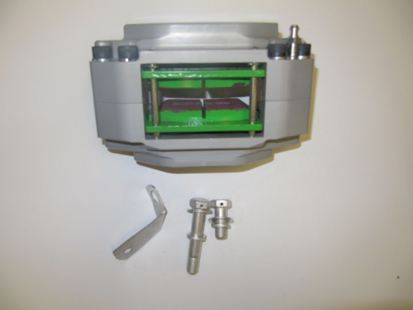
The photos above show the upgraded EBC “Green Stuff” brake pads. After installing the vented rotors on the front suspension crossmember assembly I installed the calipers finding that it appeared that no shims would be needed for proper fit.  Two bolts secure each caliper to the stub axle housing lugs: The shorter 1/2″ x 1 1/8″ – 20 is at the upper mount and the longer 1/2″ x 2 5/8″ – 20 is at the lower mount. Each bolt is accompanied by a flat washer and a split washer. The cad plated brackets were used on the original brakes to support the union of the rubber brake hose to the metal caliper pipe. With the Coopercraft upgrade these are not used, as the hose links directly to the caliper.

However, I found that sliding the EBC pads into the caliper, on either side of the rotor, was difficult and the concluding fit was much tighter than I liked. After checking with Coopercraft, they advised that the EBC pads are about 2mm wider than the standard pads. I volunteered that while I was looking for an “upgraded” braking experience, I was not going to be racing the car. They suggested that I might want to go with standard pads rather than the EBC pads. They also recommended that if I was going with standard pads in the front brakes that I should do the same with the rear brakes. Oh well, just wasted money once again!

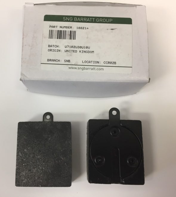
I ordered standard front pads to fit a Series II/III E-Type (the proper pad to fit the upgraded alloy calipers) JLM 9515 as well as standard pads for the rear 10821* from SNG Barratt and they fit just as they should. Wish that I had ordered the Mintex pads to begin with!
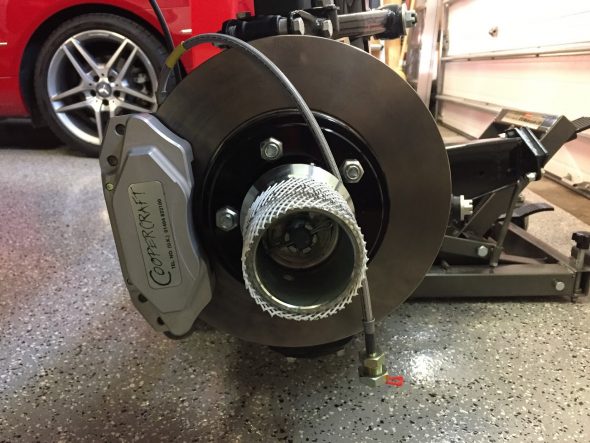
Coopercraft Vented Rotors, Alloy Calipers fitted with Goodridge Stainless Brake Hose and Hubs installed
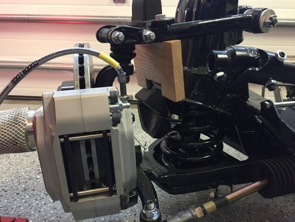
Coopercraft Vented Rotors and Alloy Calipers with Standard Mintex Pads and Hubs Installed

Anti-rattle clips are added after the pads and pins are installed. These spring clips are part number 12292 and a total of four are required.
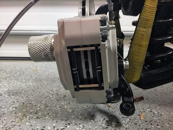
Anti-Rattle Spring Clips for Brake Pads Installed
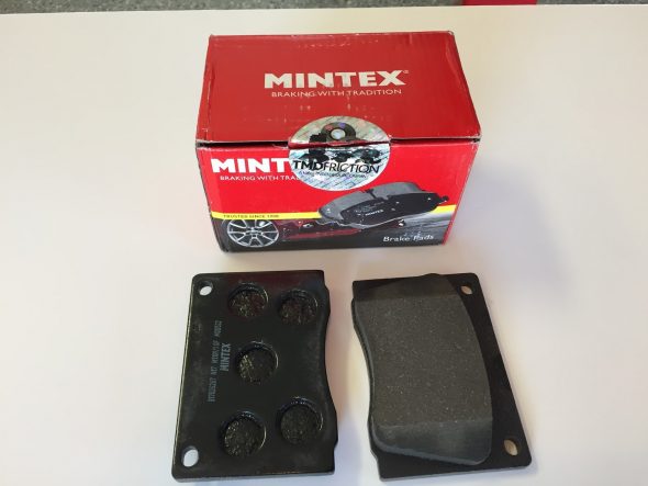
Mintex Front Caliper Brake Pads


I replaced the original rubber brake hose with Goodridge stainless hoses. The larger fitting on the end of the hose is metric, 16 mm diameter – .50 with with a 16mm -.50 nut.
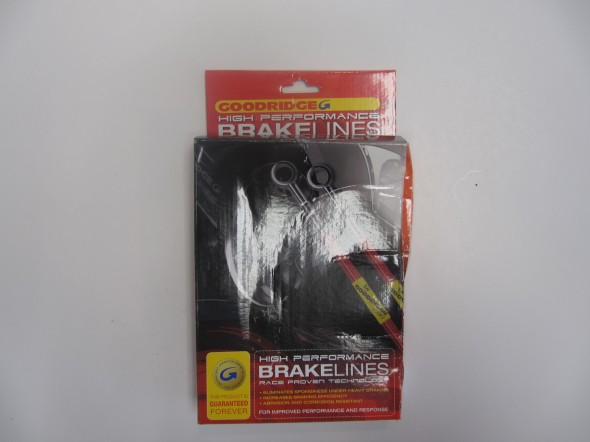
Goodridge Stainless Brake Hose

Goodridge Stainless Brake Hose

After mounting the calipers I safety wired the caliper mounting bolts. 
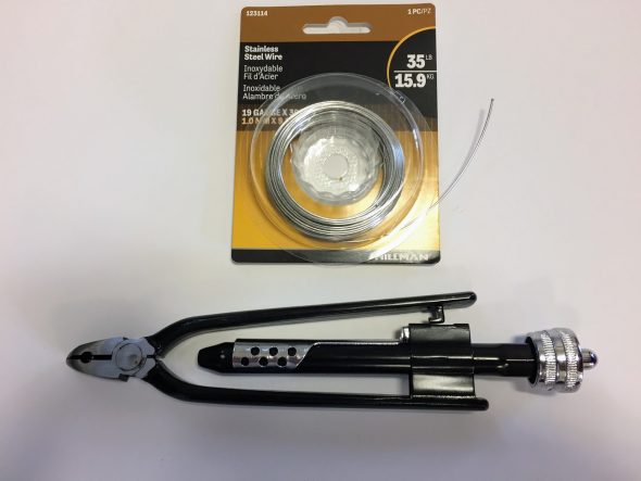
Stainless Safety Wire and Twist Tool

I used 19 gauge wire that is probably a little heavier than needed but it worked just fine. If you are doing safety wiring, it can certainly be done with regular pliers, but the twist tool gives a very nice uniform appearance to the wire and is easy to use. 
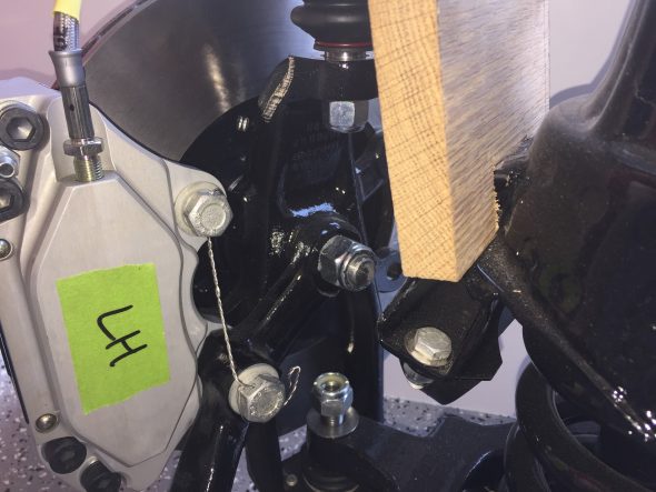
Safety Wire on Front Brake Calipers

No videos are perfect, but this short video gives you a pretty good look at how safety wiring should be done. There is sound but screen captions are used initially.

Rear Brake Upgrade

In the rear, the Coopercraft upgrade kit consists of four redesigned and uprated cylinders, incorporating stainless steel pistons in an alloy caliper. This kit utilizes the standard handbrake mechanism and is designed to maintain a good balance with their uprated front sets. As stated previously, I did not use the EBC pads and instead substituted the standard pad provided by SNG Barratt.
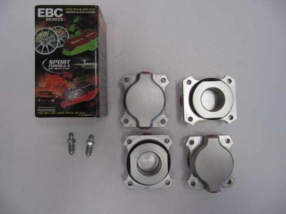
Alloy Rear Brakes
Alloy Rear Brakes

Rear Brake Friction Pads

The small tabs with holes in each brake pad is to permit the insertion of a hooked wire to pull the pad out when it is replaced. The pads are held in place by the Retaining Plate for Friction Pads as seen below with mounting hardware.
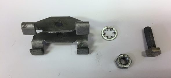
Rear Brake Friction Pad Retainer with Fasteners

The image below shows the Coopercraft Alloy Pistons and Housings installed in the original calipers with new pads secured by the pad retainer. 
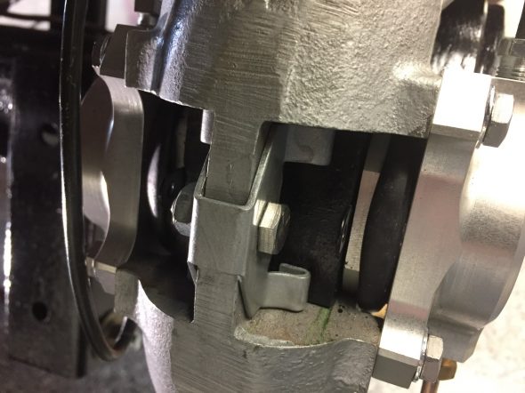
RH Rear Brake Caliper with Retaining Plate for Friction Pads Installed

The calipers need to be centered around the rotors and this is accomplished with the use of shims on the two bolts securing the calipers to the axle. On my car, I use five .010″ shims on the upper bolt of the RH caliper and five .010″ shims on the lower bolt. On the LH side, I used no shims on the upper bolt and two .010″ shims on the lower bolt.

Following assembly, I safety wired the mounting bolts for both rear calipers.
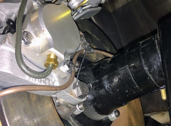
Safety Wired Rear Calipers

A warranty is also provided by Coopercraft:
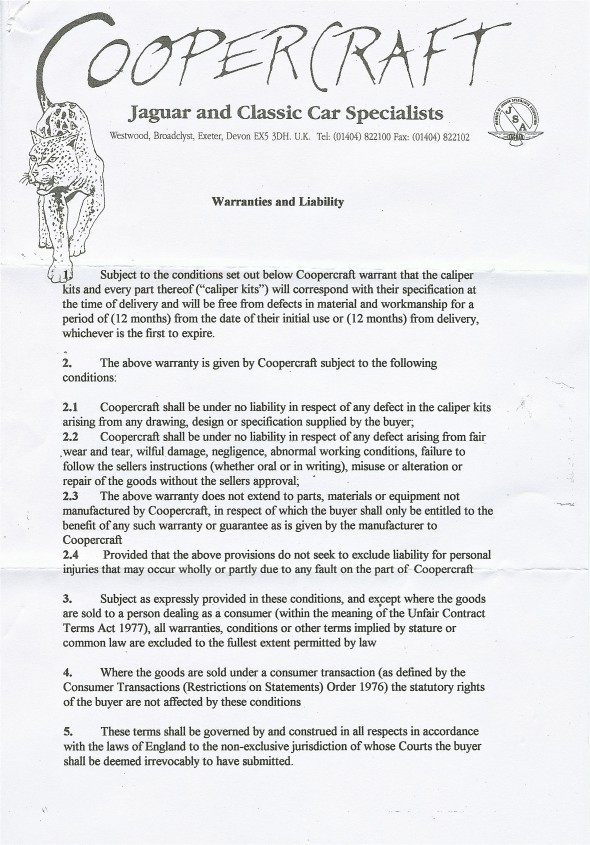
Coopercraft Brake System Warranty and Liability

Coopercraft Brake System Warranty and Liability

Rear Brake Caliper Rebuild
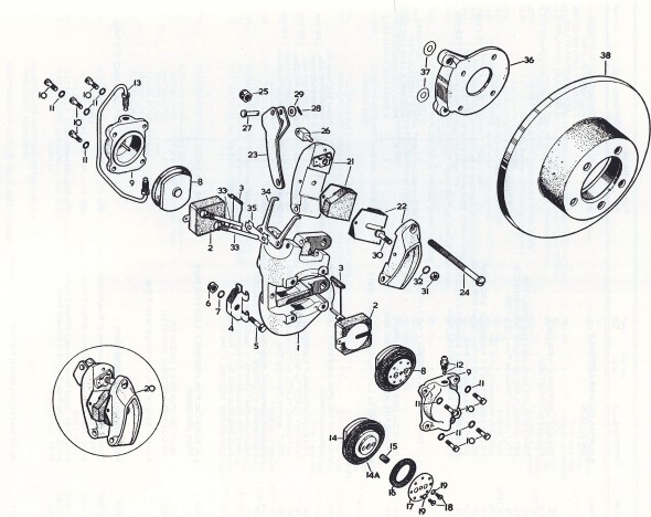
Rear Brakes

Rear Brakes

In addition to adding the new Coopercraft Piston/Cylinder Sub-Assemblies I completely rebuilt the Rear Caliper Assemblies including the Handbrake Calipers. As the image below illustrates the original silver color was long gone!
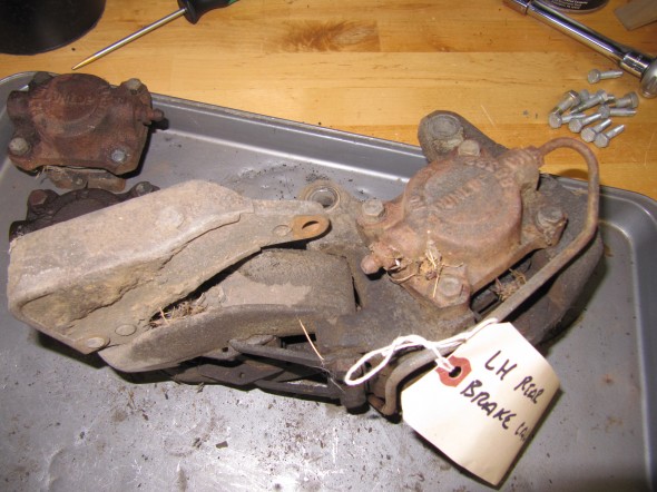
Left Rear Brake Caliper

Left Rear Brake Caliper

To disassemble the calipers, I first separated the handbrake calipers from the primary caliper. To do so, I bent back the tabs on the Tab Washer and unscrewed the two Bolts, Securing Handbrake Mechanism to Rear Calipers. I then removed the Retraction Plate Fork that permitted the removal of the LH and RH Handbrake Pad Carrier Assembly with the friction pads. The Bolt, Securing Pad Carriers to Operating Lever was then unscrewed separating the two Carriers. I then removed the Support Plates for friction pads which simply fit into slots on the caliper body. Four 1/4″-24 x 7/8″ hex head bolts with shakeproof washers secured each Piston/Cylinder Assemblies. These were removed and the assemblies with the friction pads were removed. The Retaining Plate for friction pads was held in place with a 1/4″ – 24 x 7/8″ hex head bolt. It was removed and will not be replaced until the caliper is mounted and the new friction pads are installed. The Bridge Pipe Assembly and the Bleed Screw and Ball Assembly were removed from the Piston/Cylinder Assemblies and replaced with a new pipe and fittings. All components were then media blasted or otherwise cleaned and painted with Eastwood’s silver ceramic caliper paint. New bolts and screws were installed along with new friction pads.
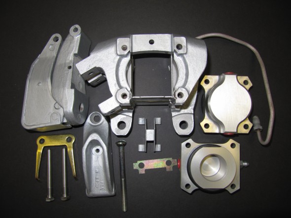
LH Rear Brake Caliper Components
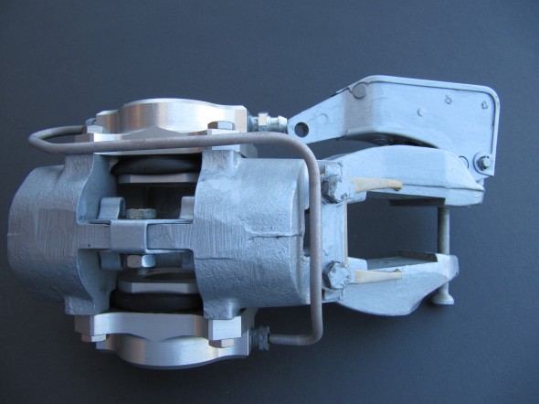
LH Rear Brake Caliper Components

Right Rear Brake Caliper Refurbished
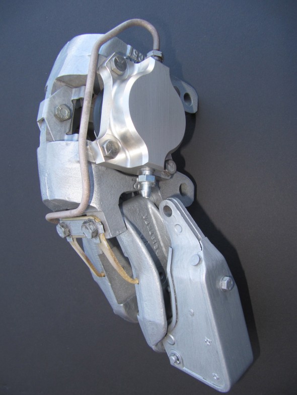
Right Rear Brake Caliper Refurbished
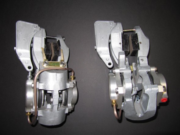
Right Rear Brake Caliper Refurbished

Right Rear Brake Caliper Refurbished

Rear Caliper LH & RH

Rear Caliper LH & RH


zz