Rear Disc Brakes
Caliper Modification
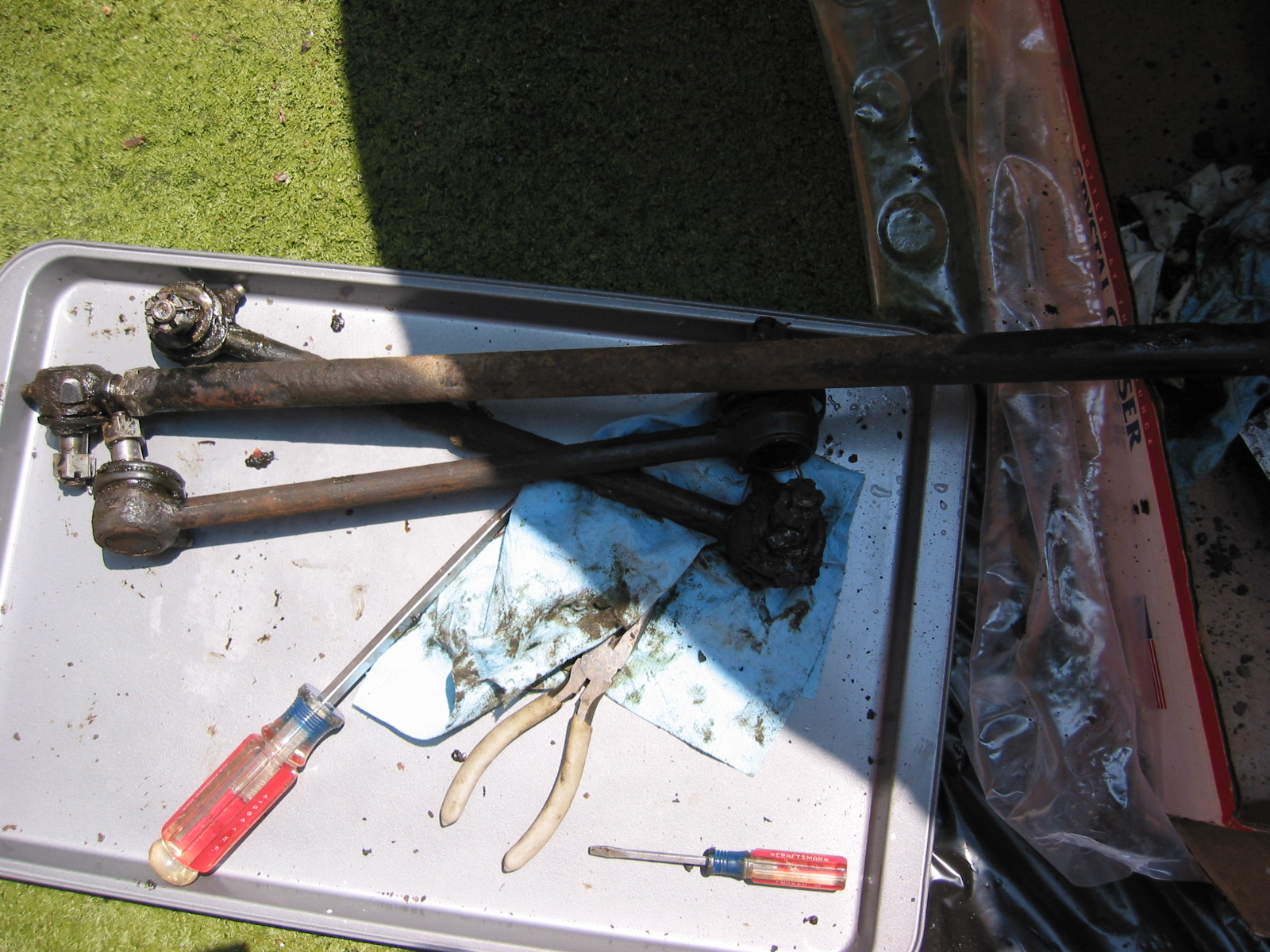
I have never been pleased with the fit of the rear brake rotors with the handbrake calipers. Steve Gerow ran into the same problem – the diameter of the rotor is about 1/4″ to great to fit the calipers properly. I like how he “fixed” the problem and when I have time I think I will take the same approach.
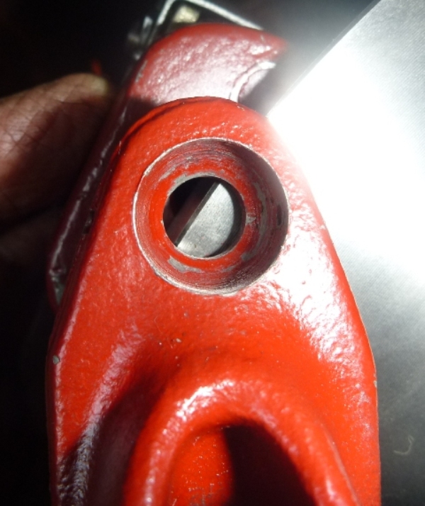
The Problem – Handbrake Needs to Be Modified
The fix – grind the housing back about .0275″ and add washer stack
Resolution
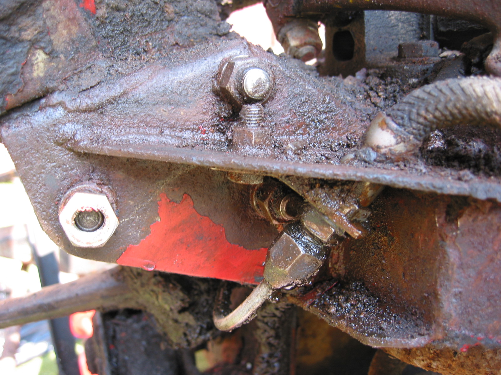
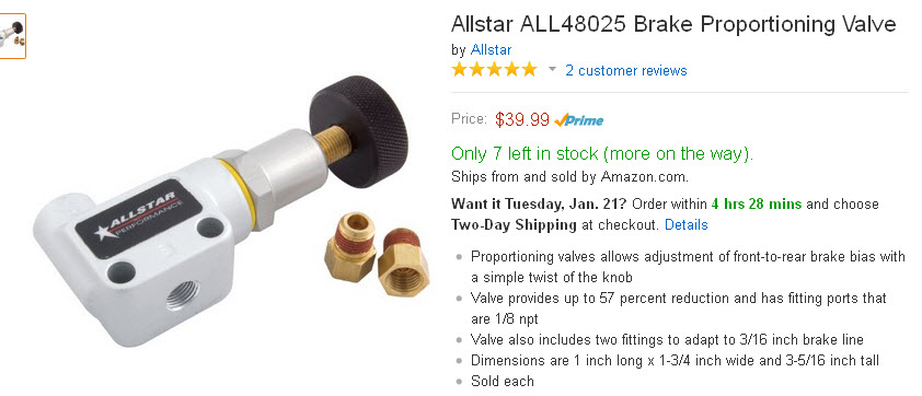
Proportioning Valve
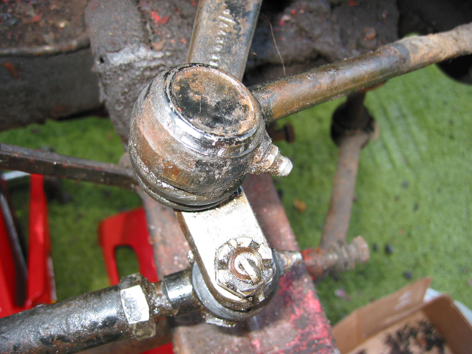
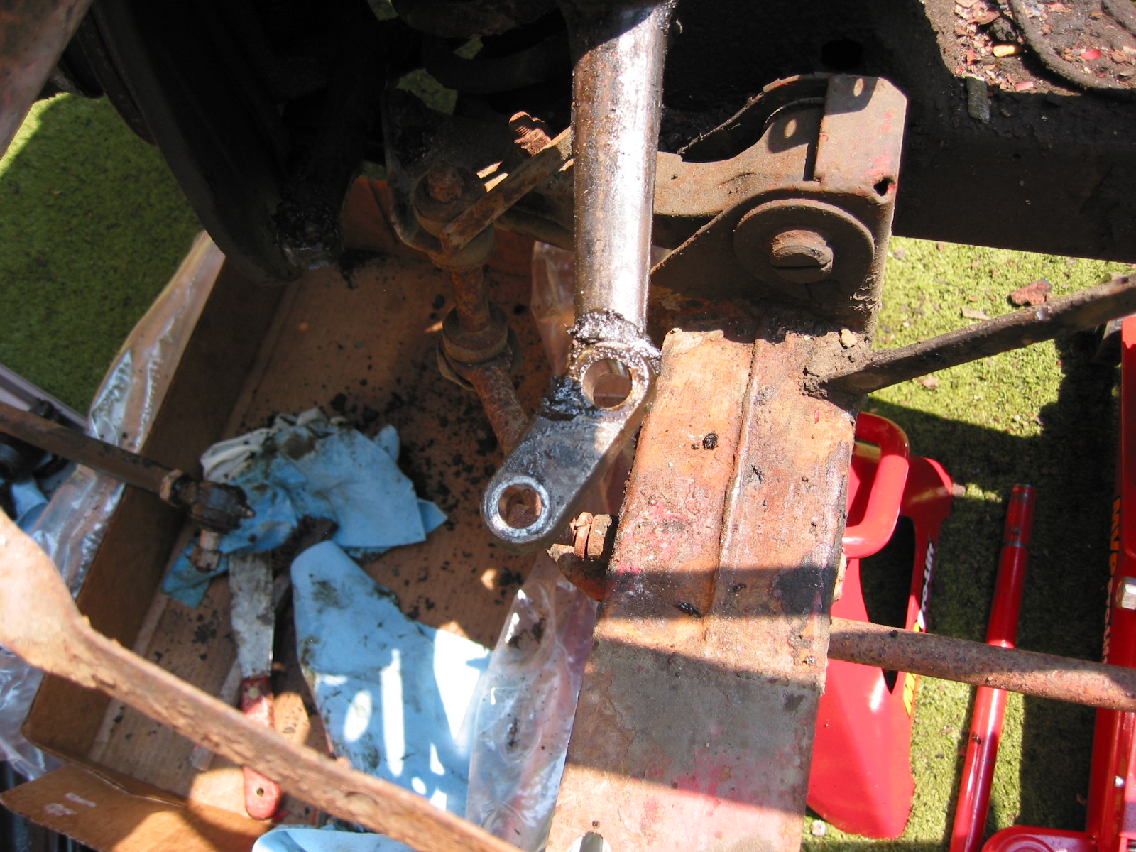
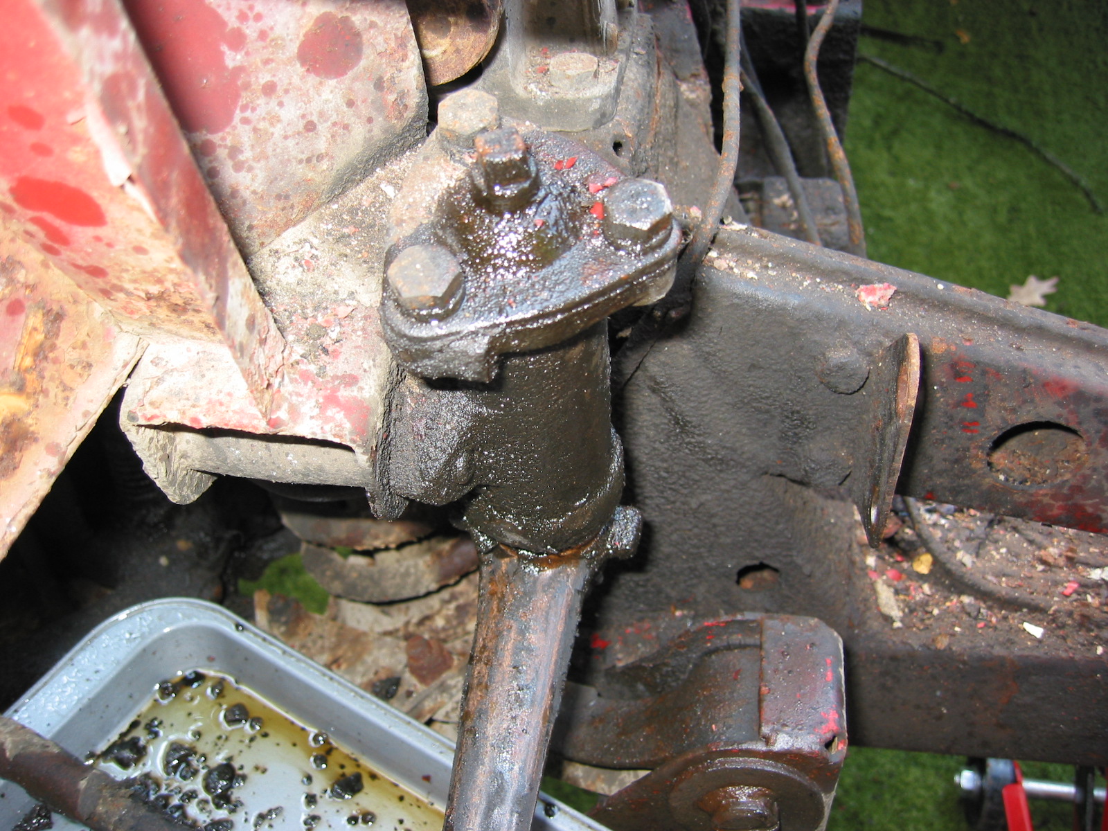
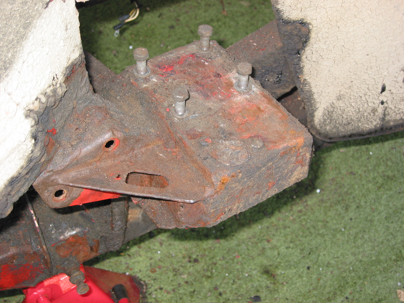
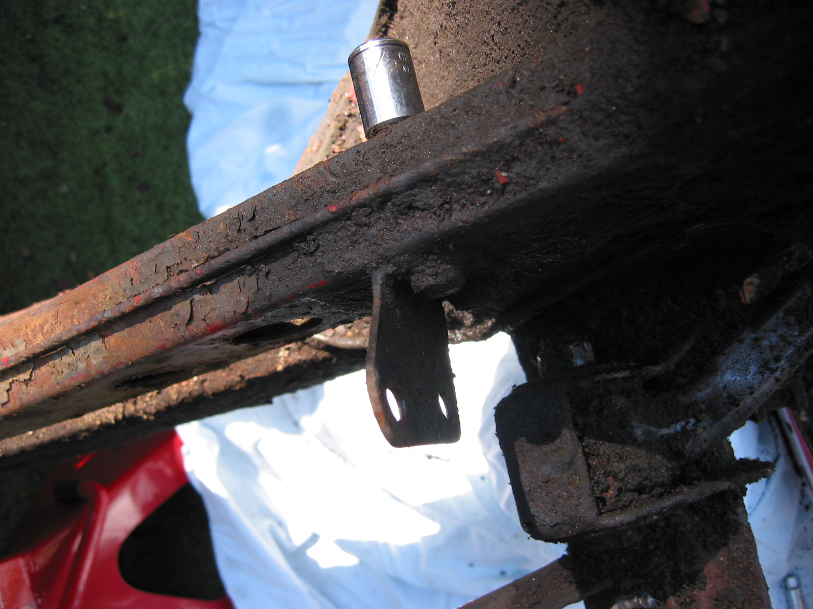
While I do not have a significant problem with the front/rear proportioning of the brakes after installing the rear disc system, some slight modification might yield a little improvement. Steve Gerow used a proportioning valve that provides the answer to optimal tuning. This is how he mounted his valve:
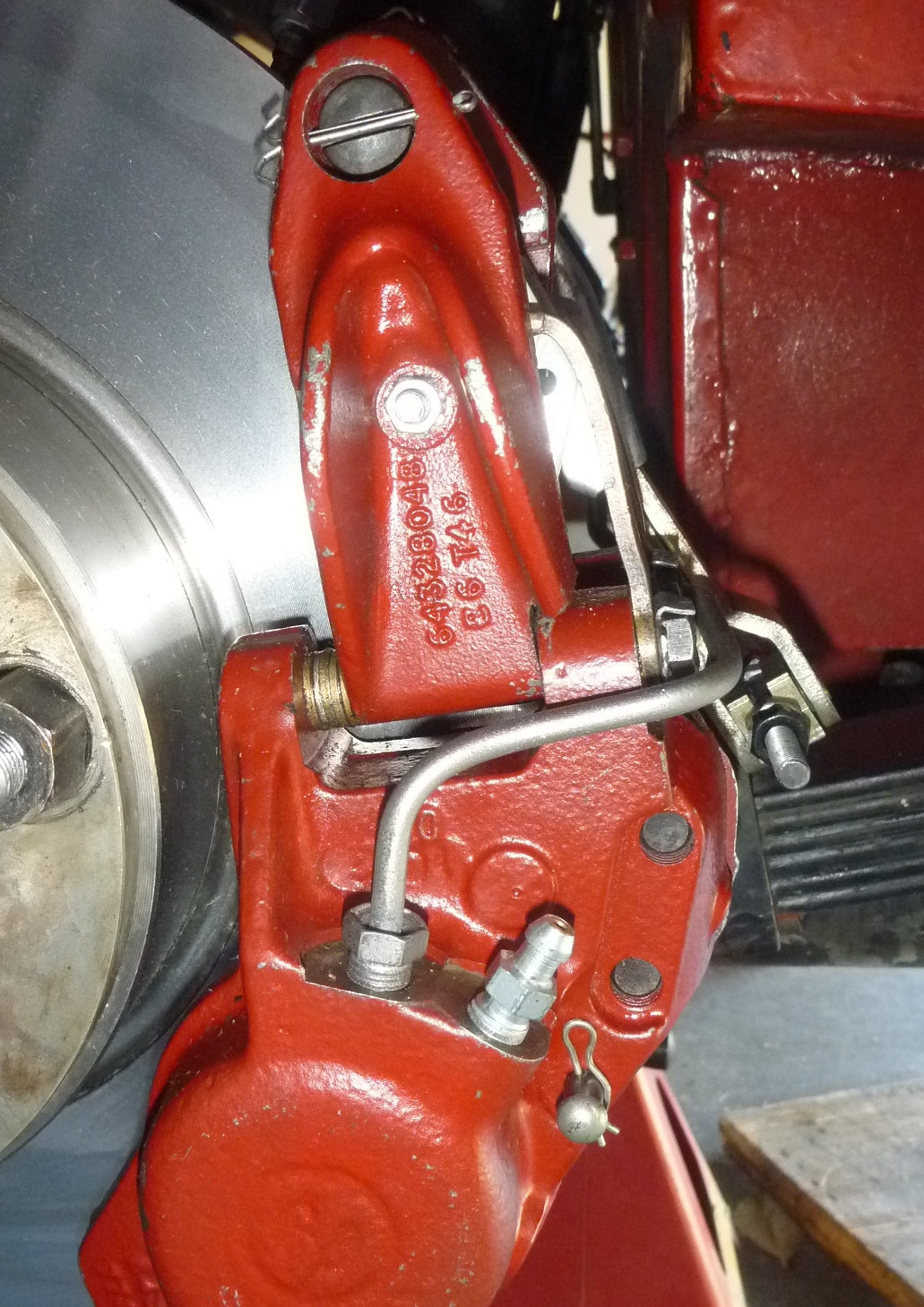
Proportioning Valve
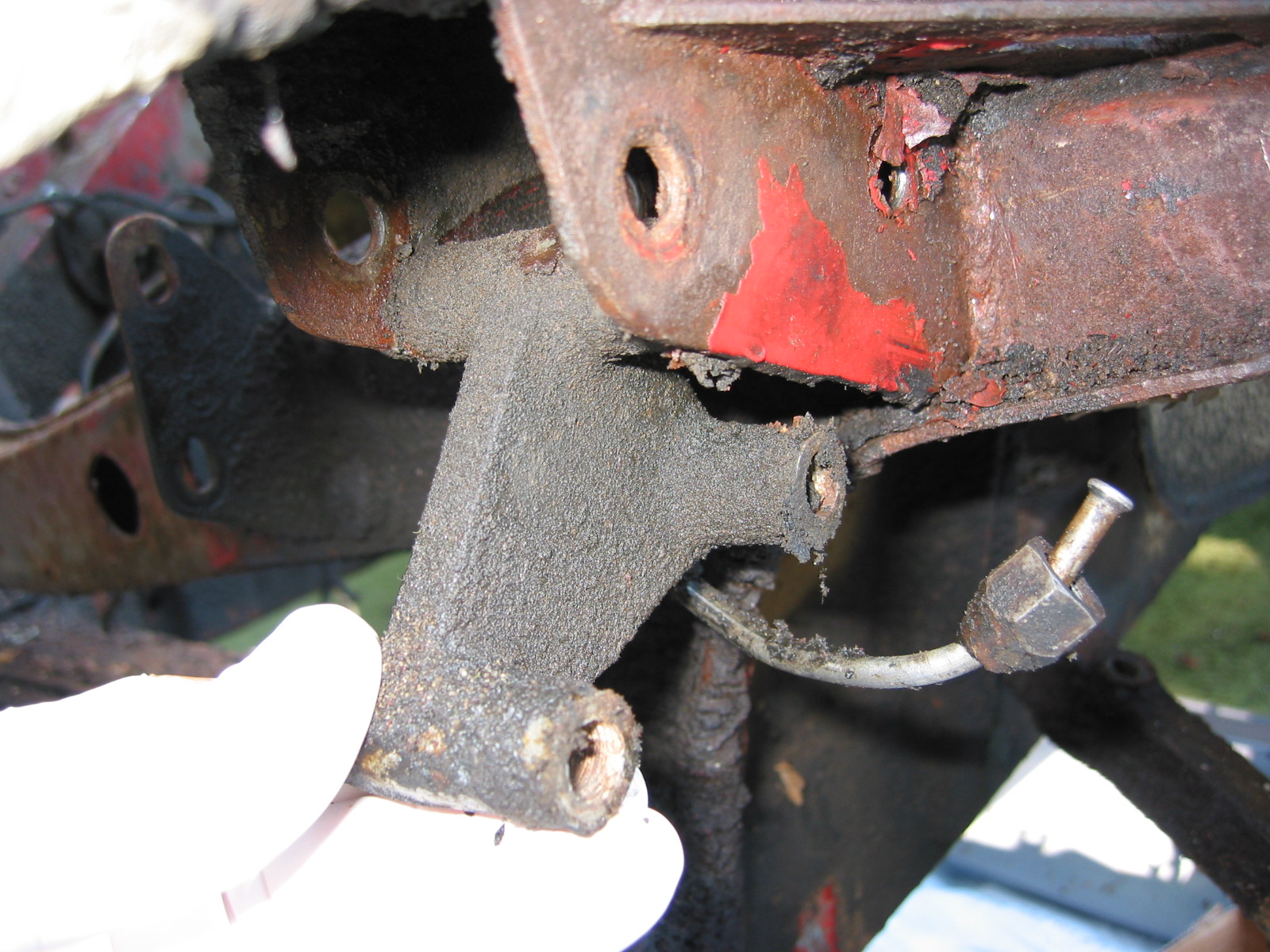
“Stock brake pipe wasn’t long enough; I cut and reflared it near the motor mount.
New line shown in photo was attached with a connector.”
“Adjustment – method was suggested with the car on jackstands:
to have an assistant lightly gradually apply the brakes while hand-turning a front and back wheel. Start with 7 turns on adjuster; adjust to the point where front brakes just locked and rears braking but still moveable.”
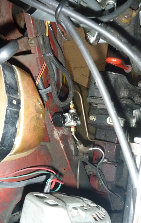
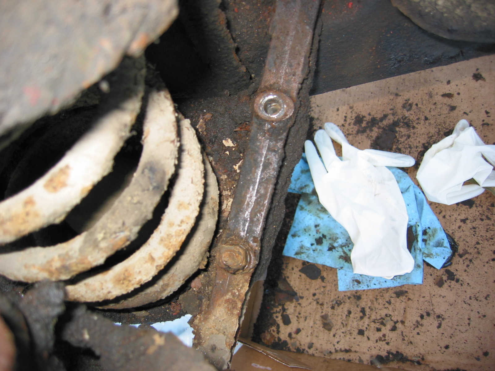
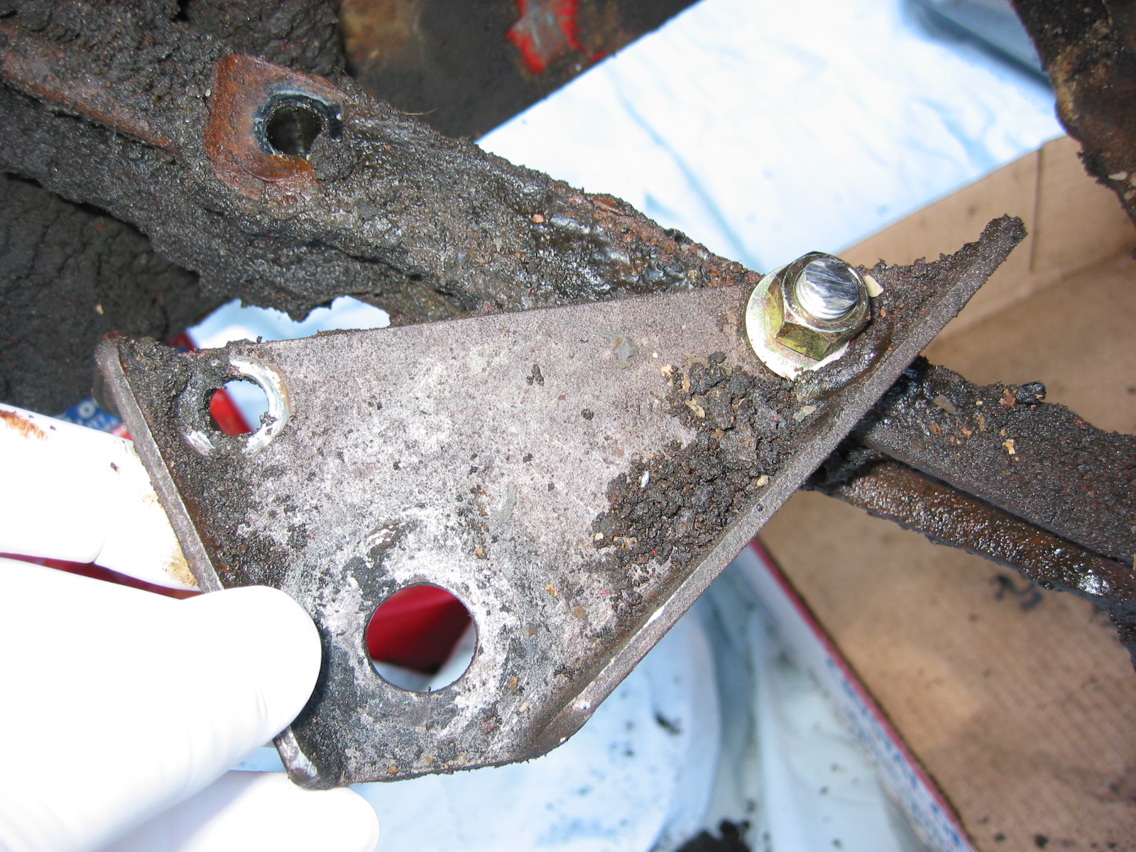
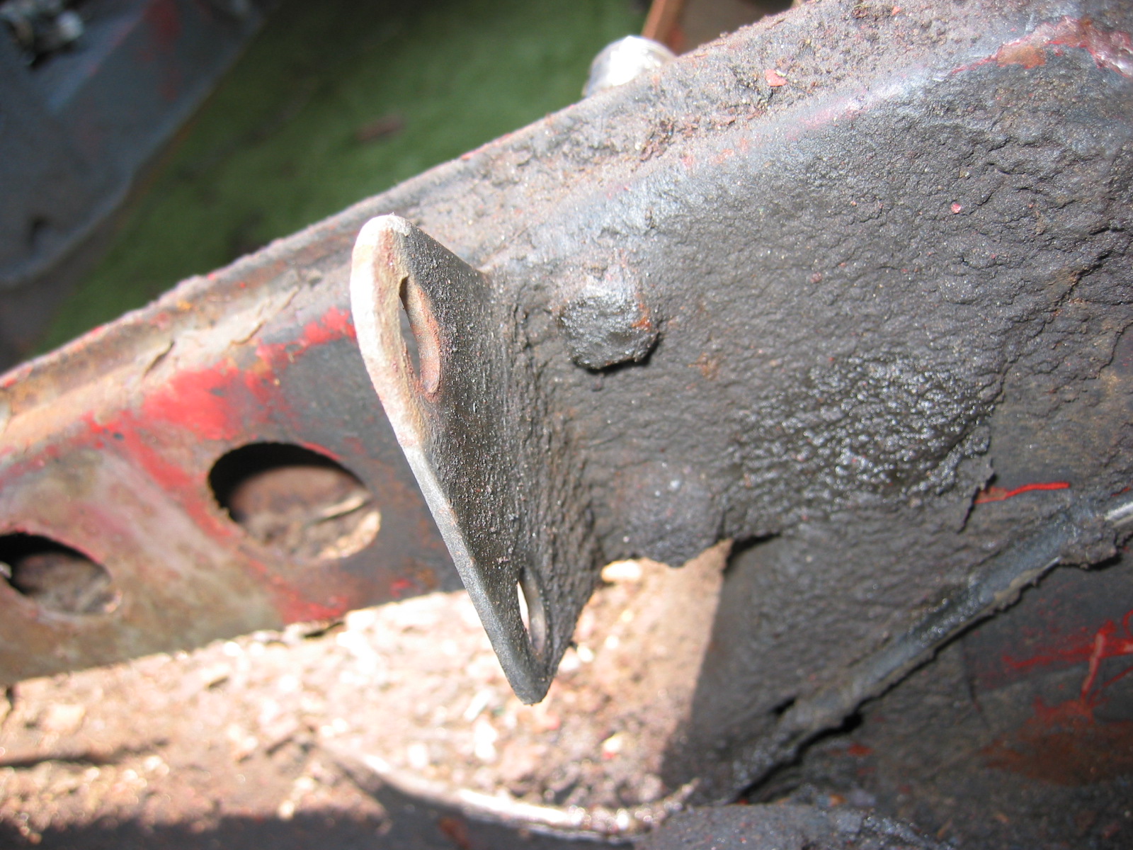
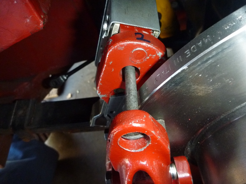
Valve Installed
Ignition Modification
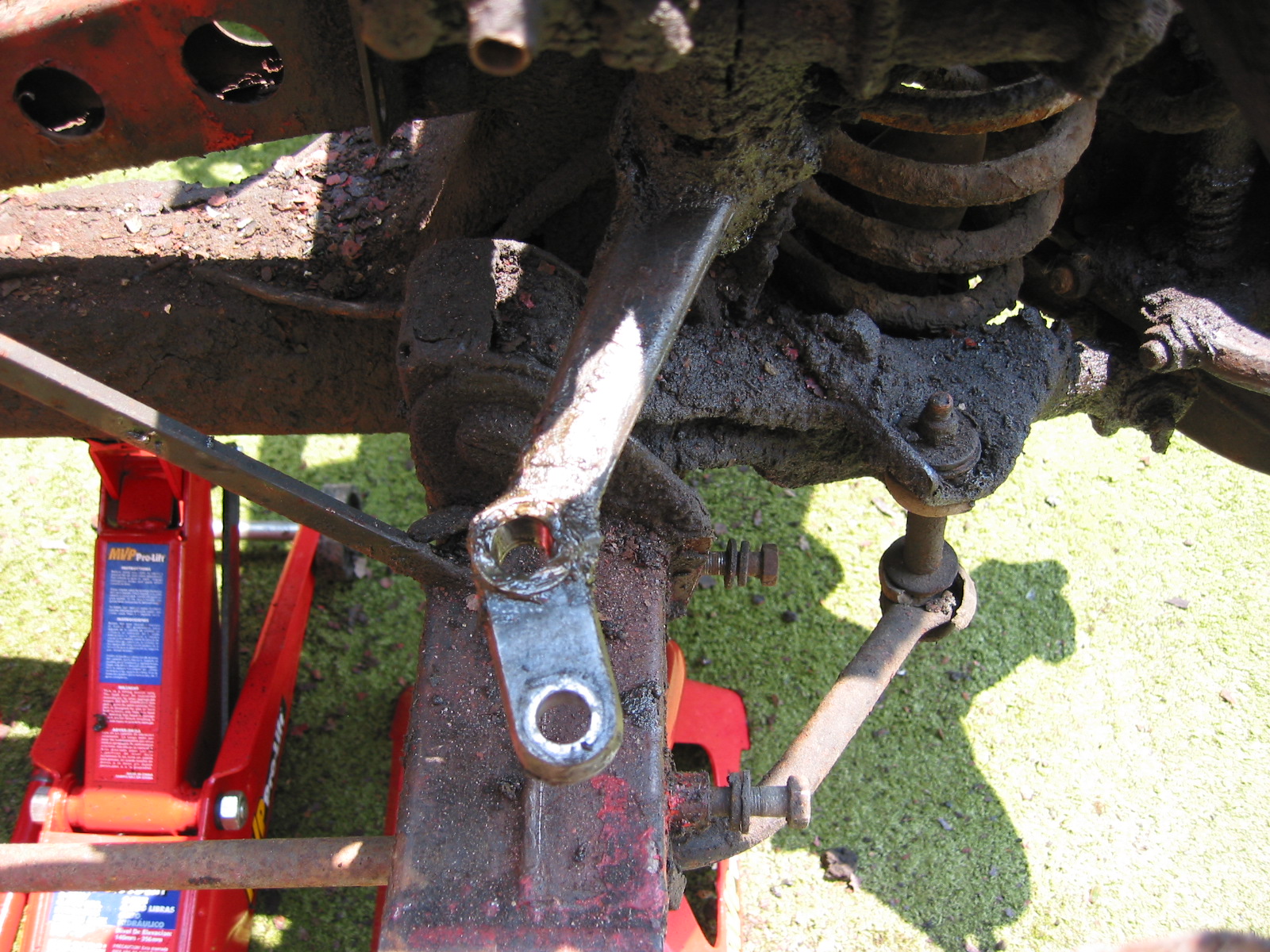
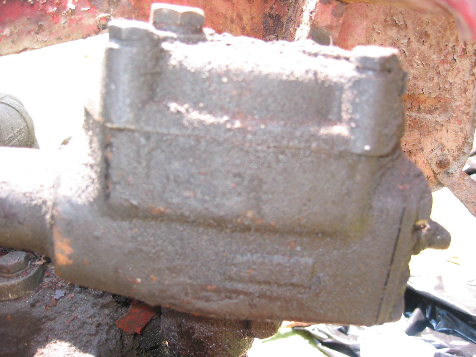
Steering Box Upgrade
At some point I would like to install new components form Denis/Welch. There is a question about standard versus high ratio.
Magnus Karlsson recommends the high ratio:
Go for the high ratio and tell your mechanic to look at my homepage. There you can see a modification I do in order to fit a modern and bigger oil seal to
the outgoing shaft of the steering box. Makes it absolutely leak free and you
can use hypoid oil as intended.
Magnus Karlsson
www.healeyspecialists.com