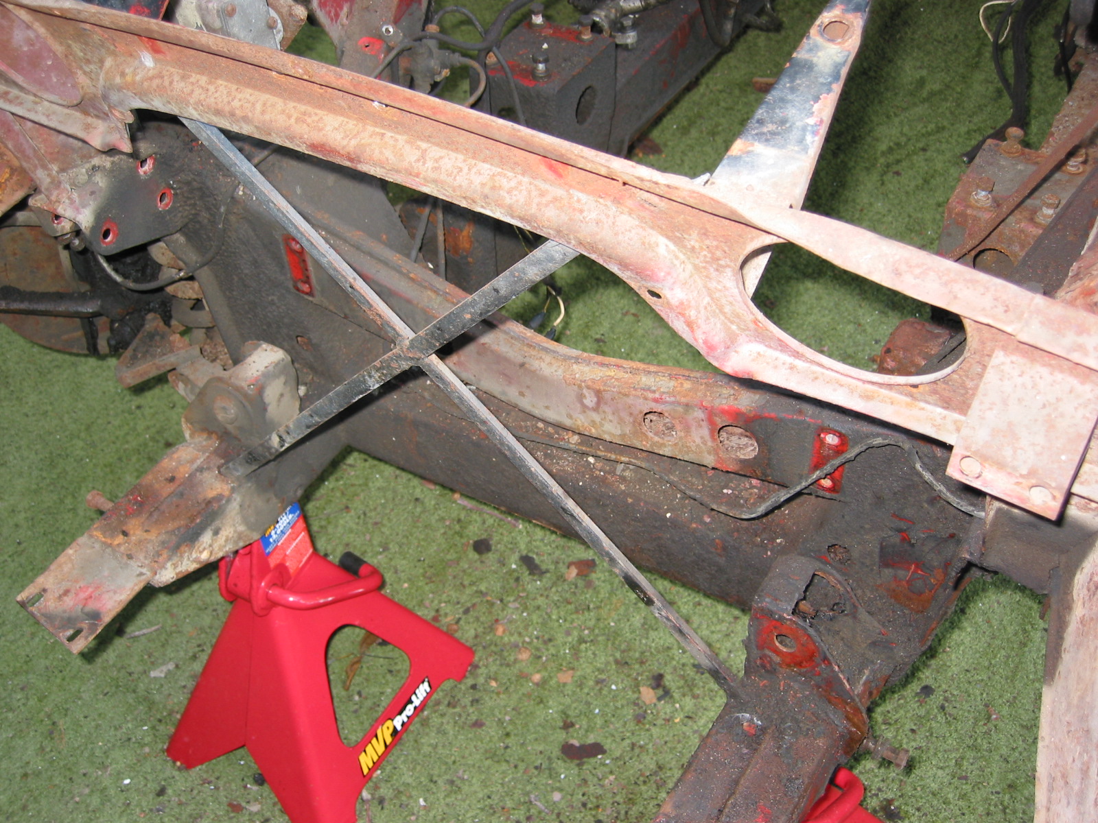
Work on the Bloody Beast was restricted to the weekend. Attention was given to the steering components of the car.
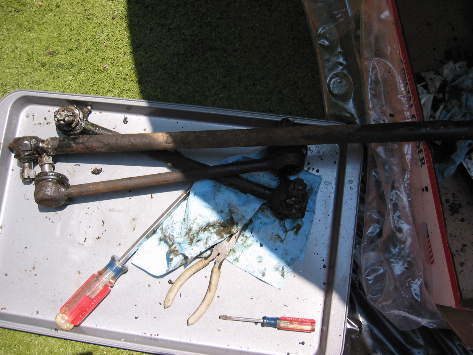
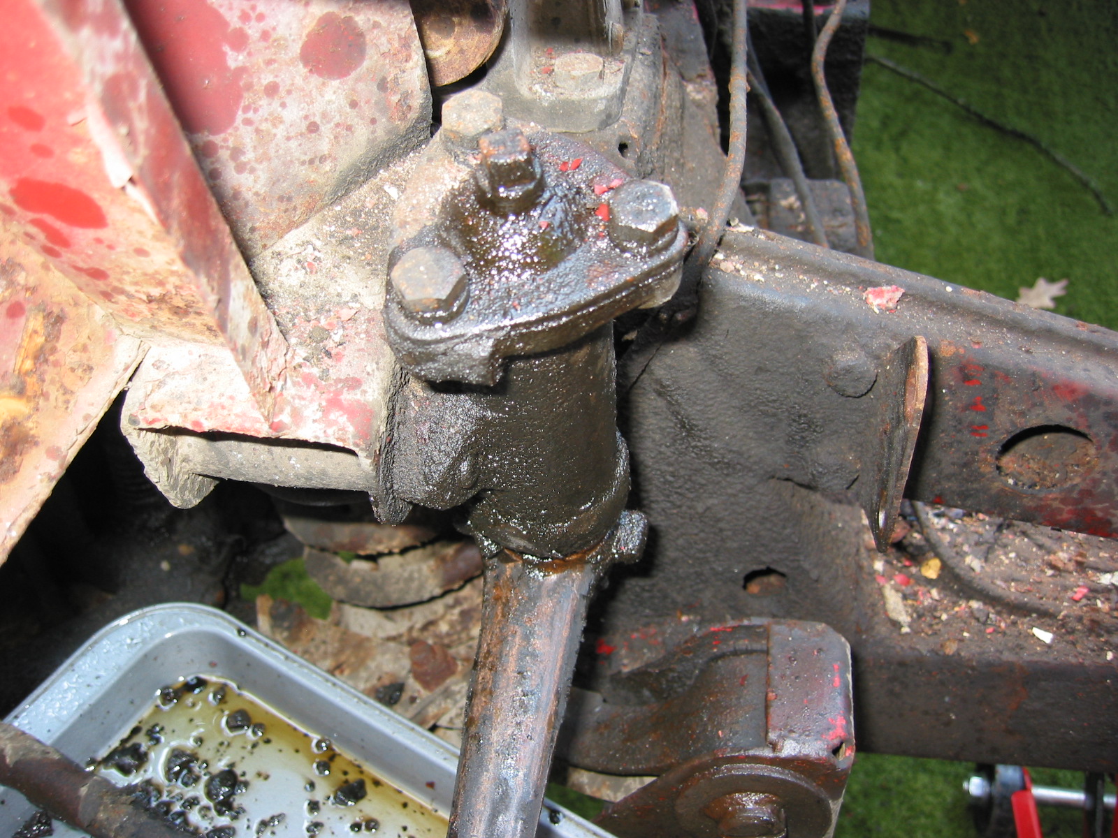
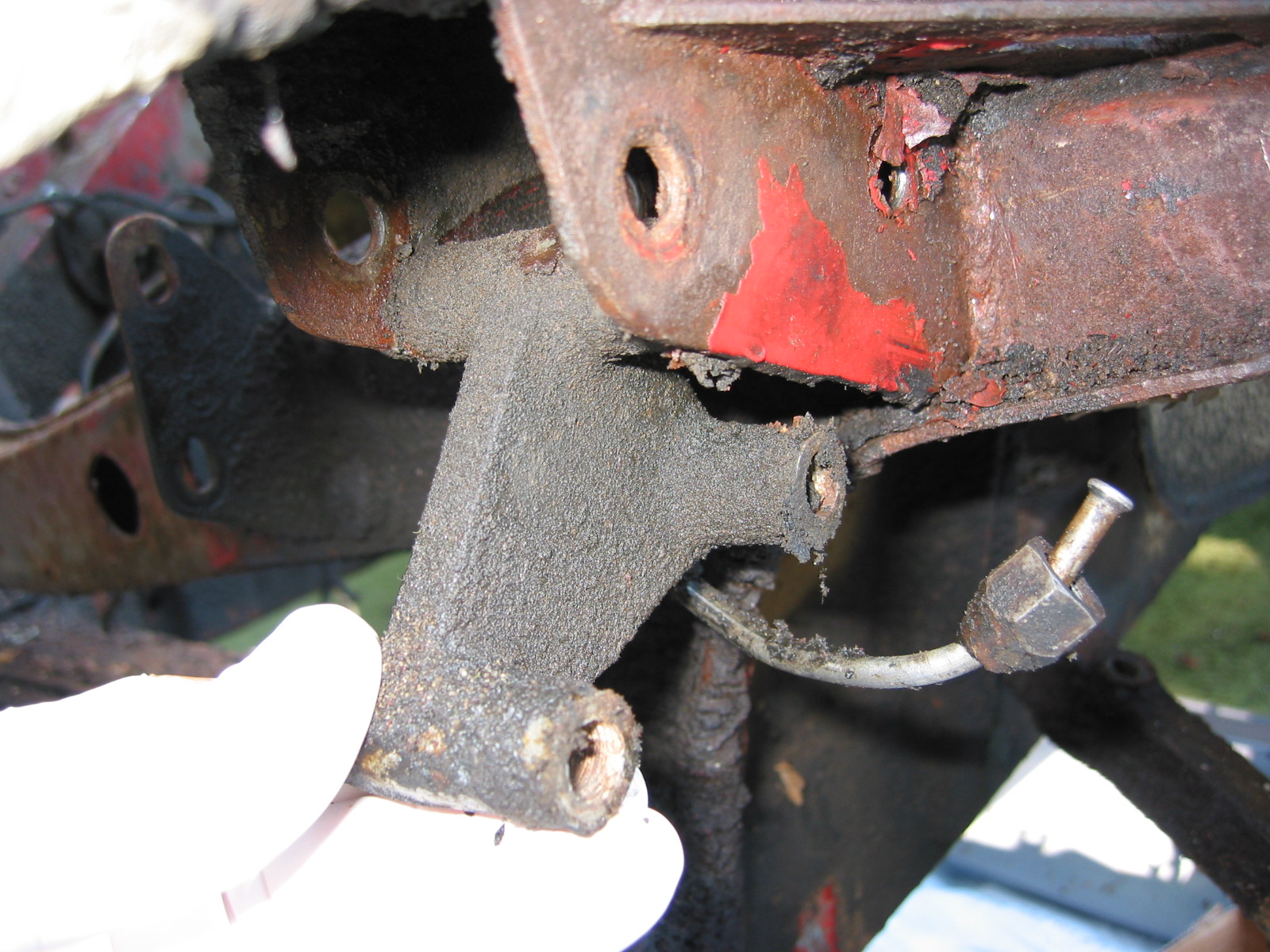
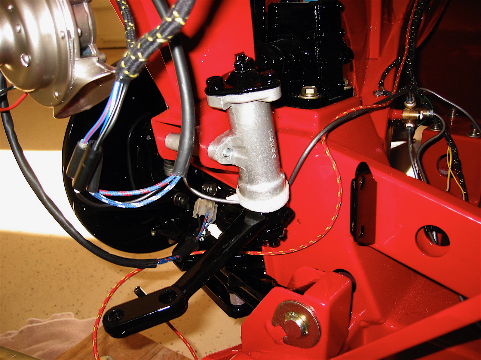
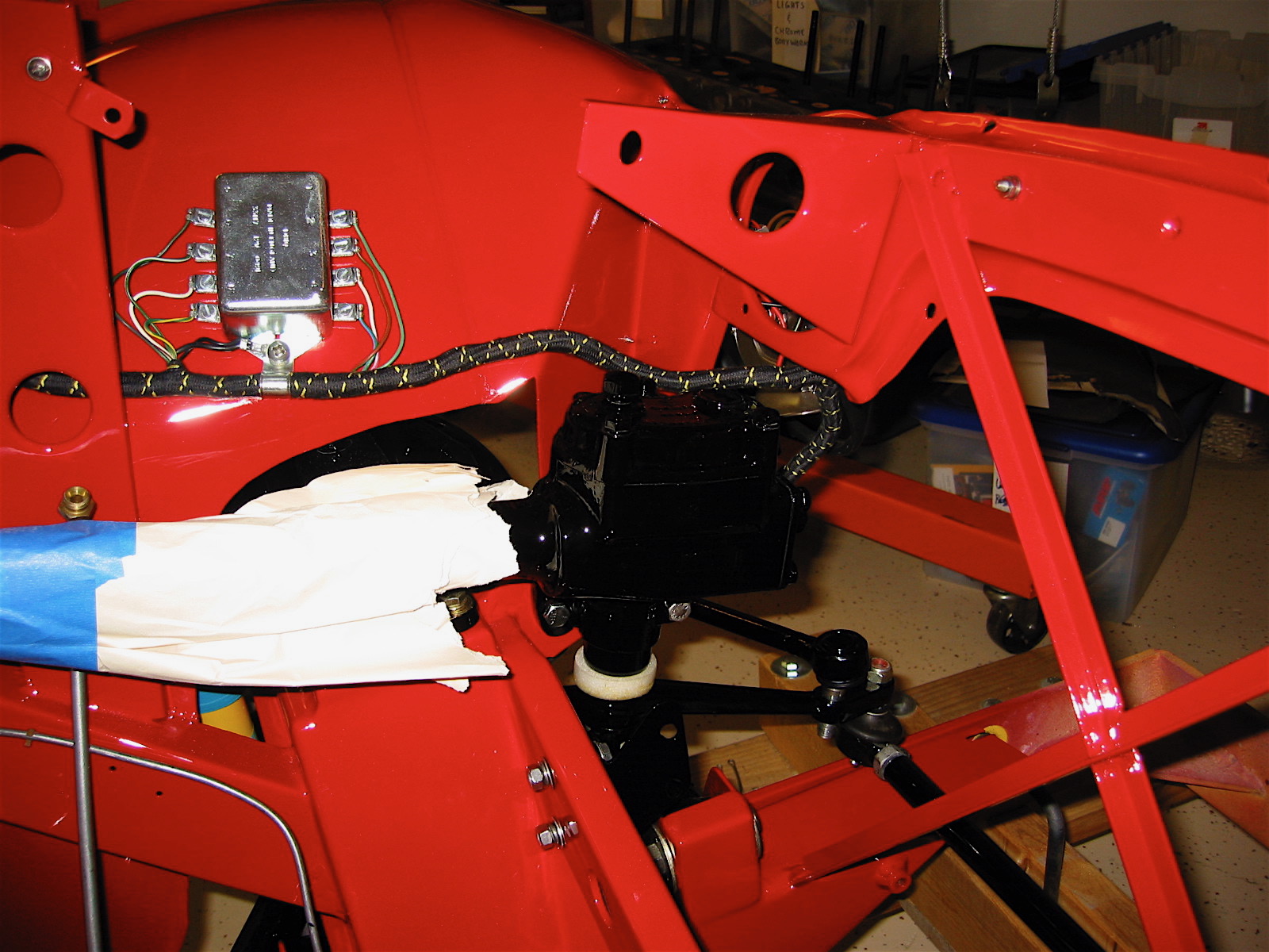
The steering idler and the steering box, along with the aluminum spacers were installed and penrite oil was used to fill the idler. The steering box will be filled later. The tie rods and the cross rod were also installed to the steering levers and the cross rod was adjusted to bring the front wheels into eye-ball (not measured) alignment.
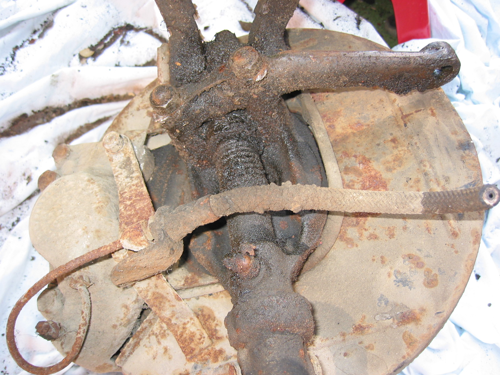
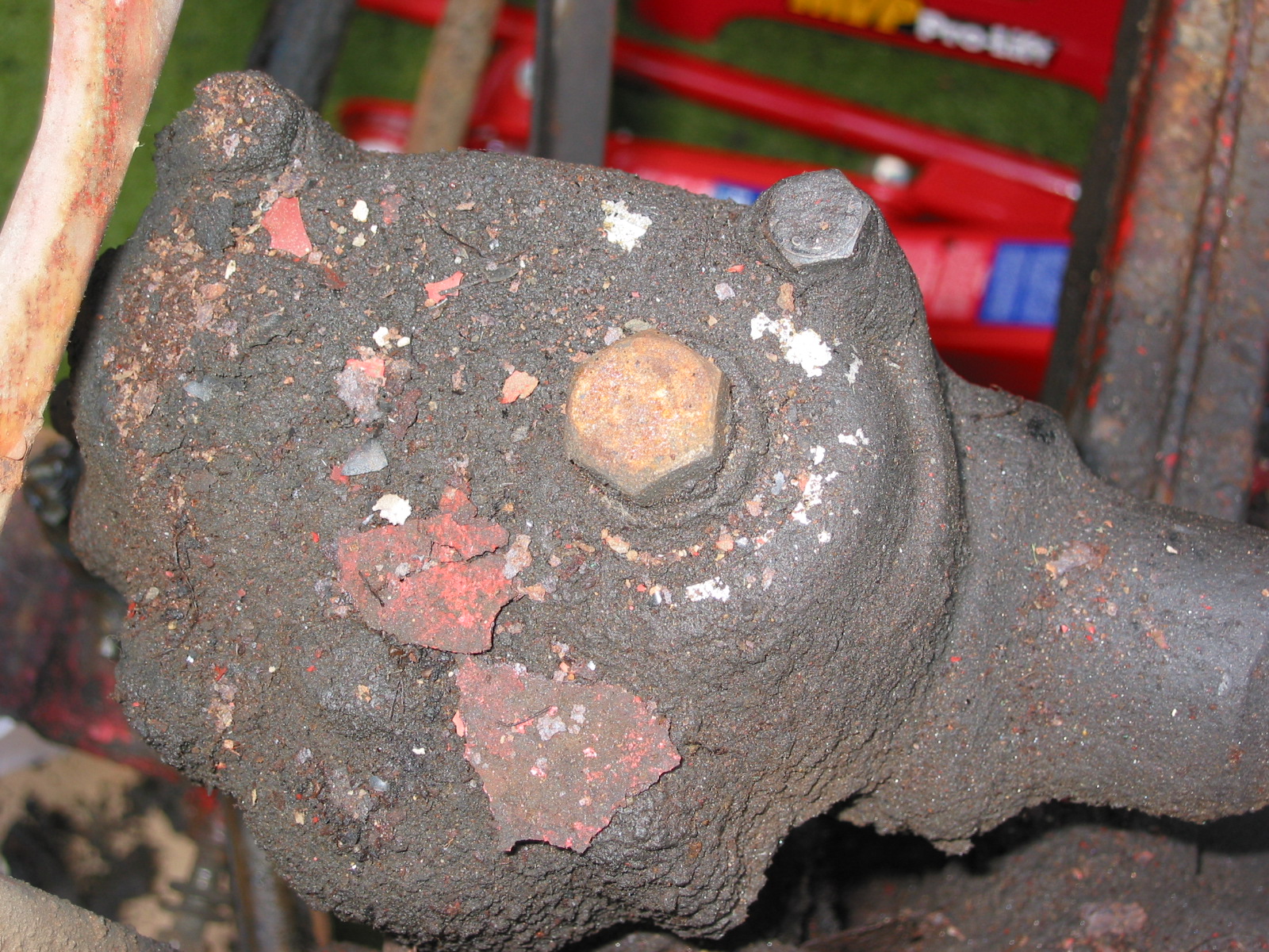
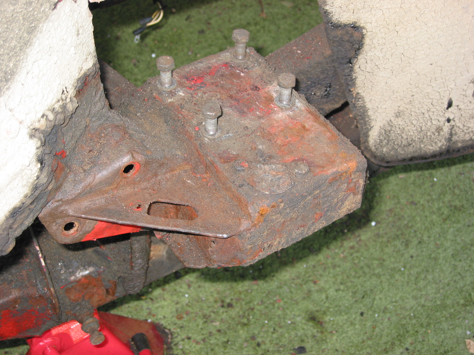
Steering Idler 1
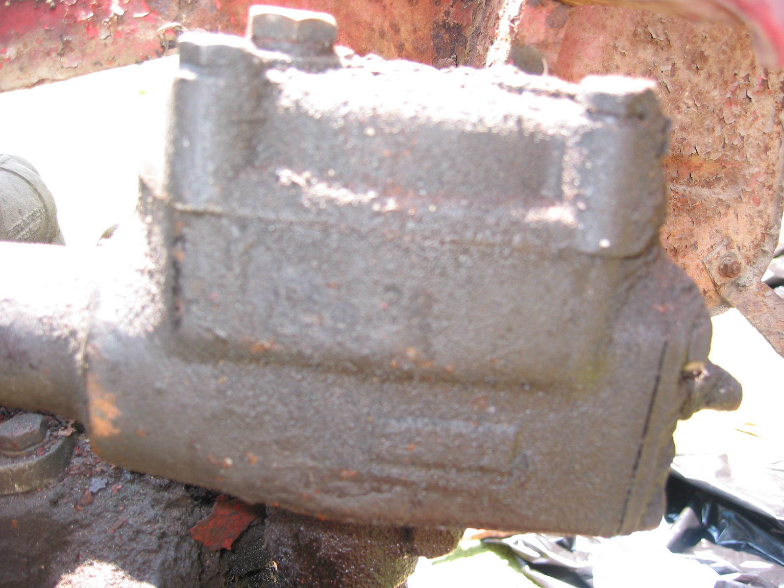
Steering Box 3

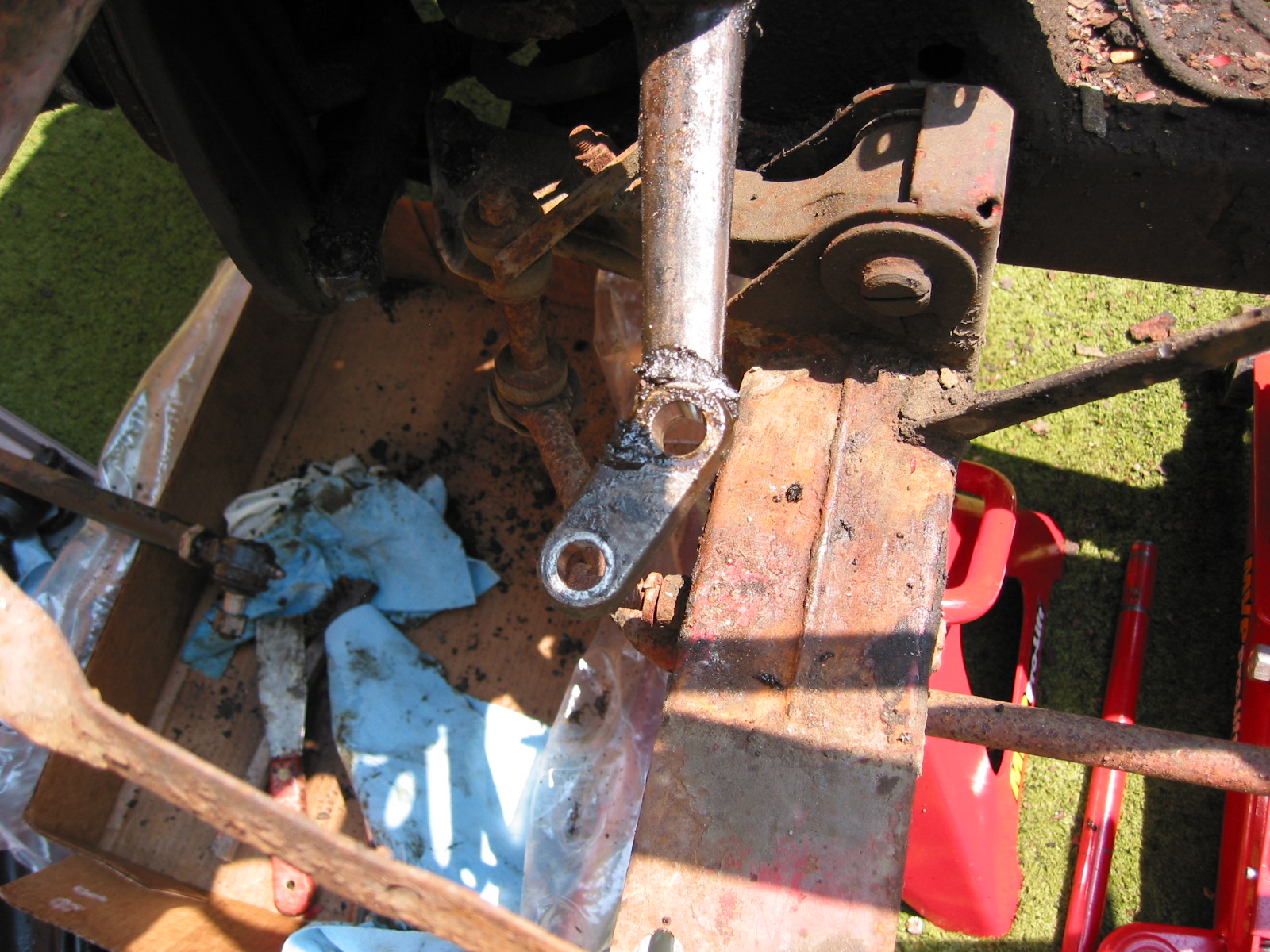
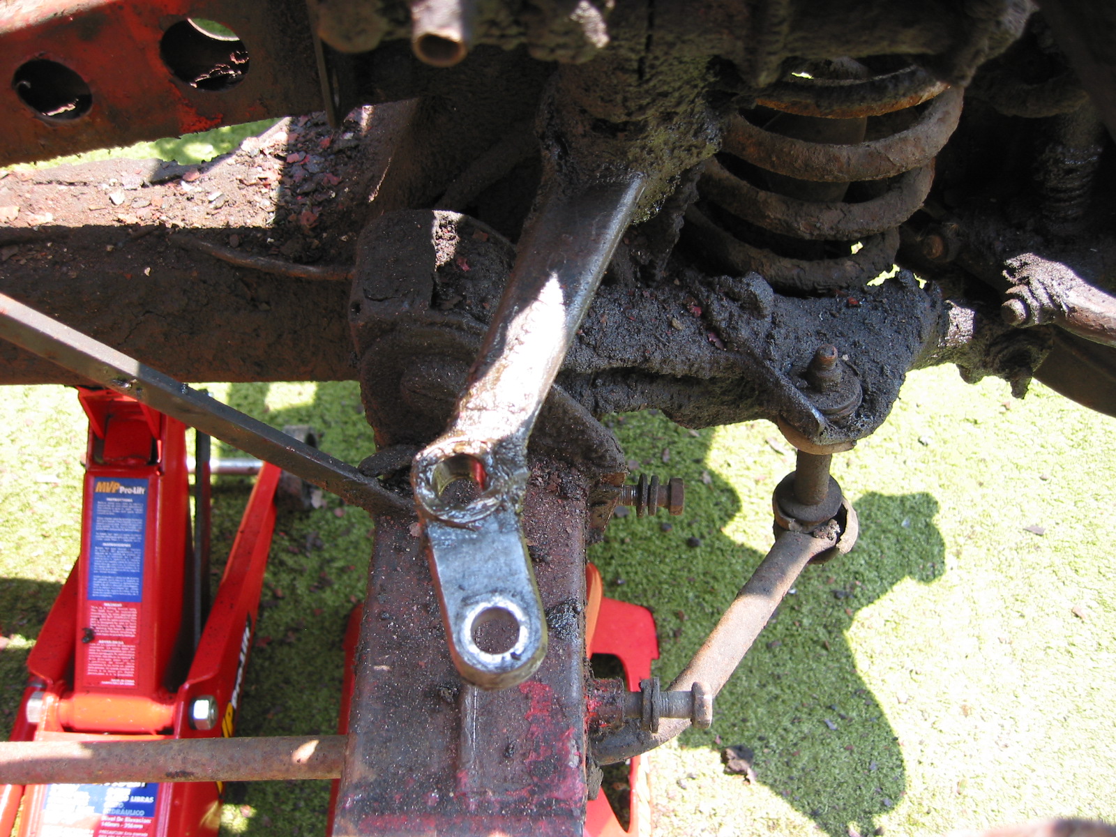
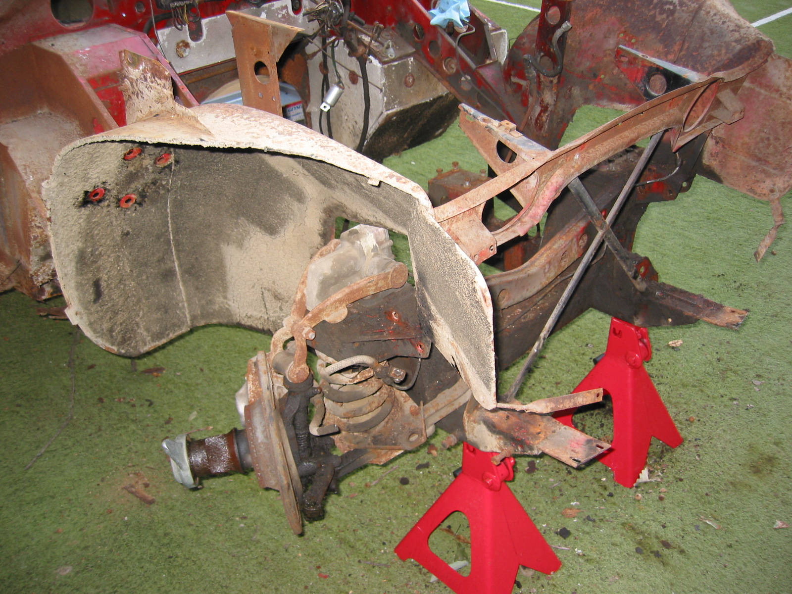
Steering Assembly
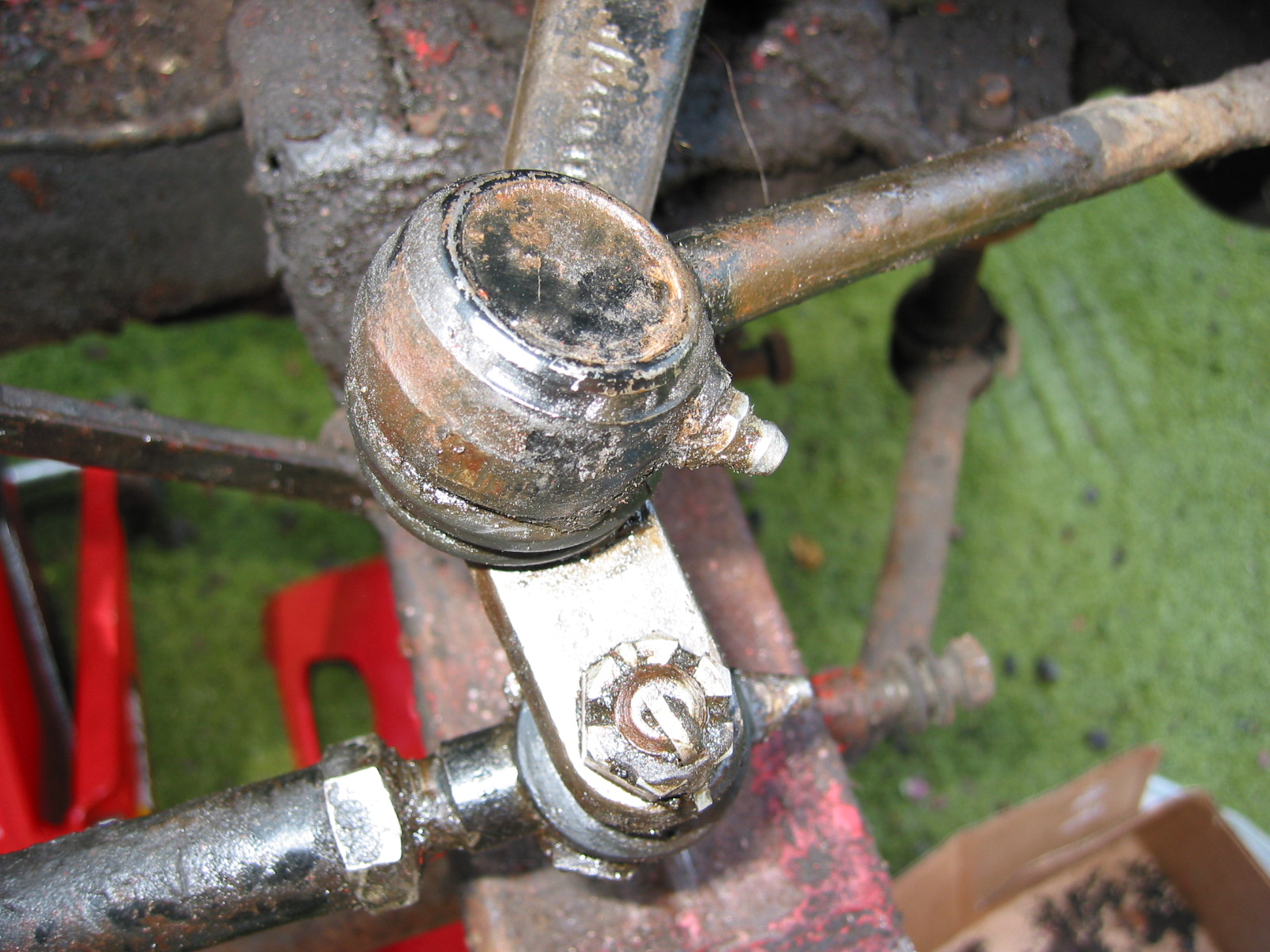
The rubber ball joint dust covers that came with the new tie rods were cracking even before they were on the car. Others suggested that Hyundai rubber ball joint dust covers, part # 56828-21010 would fit and were of higher quality so I gave them a try. Korean parts on a sixties british car – go figure.
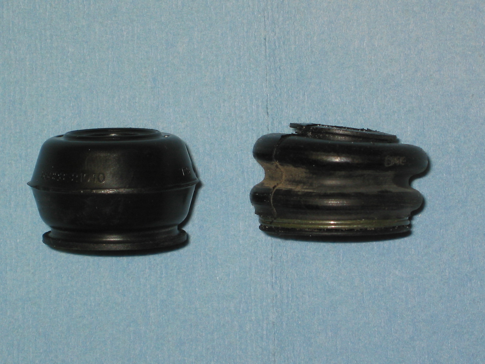
Tie Rod Dust Seals 2
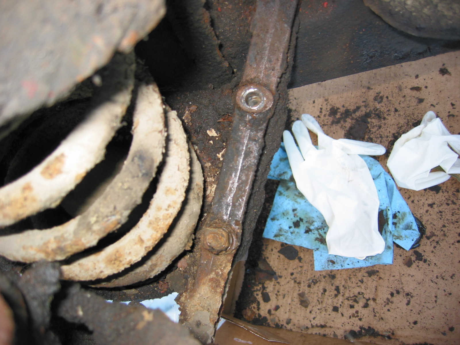
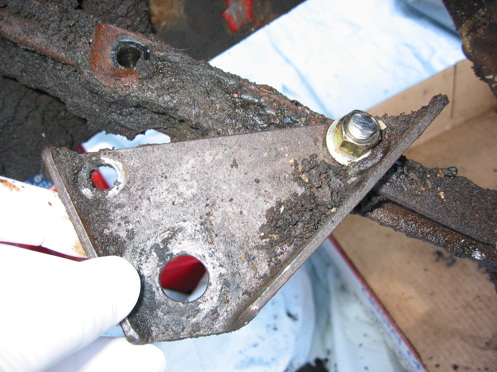
The steering bracket and steering column support clamp were affixed. The clamp was installed in the third hole from the top of the bracket as it was in the original assembly. All mounting bolts were left loose until the dash fascia is installed to determine proper alignment through the steering shaft hole in the dash.
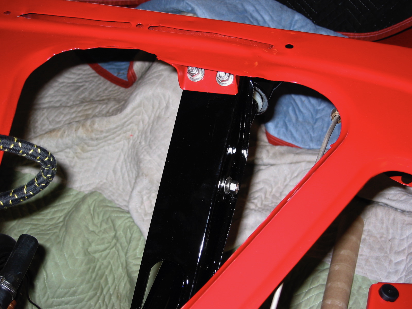
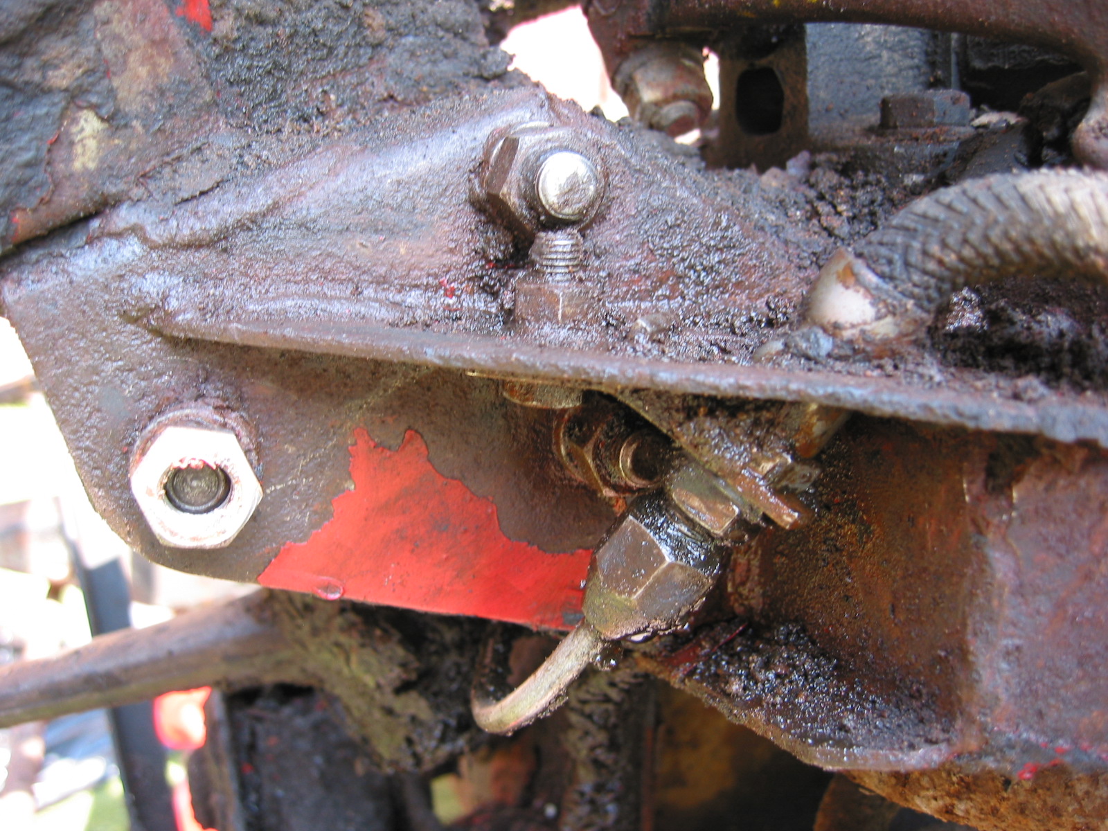
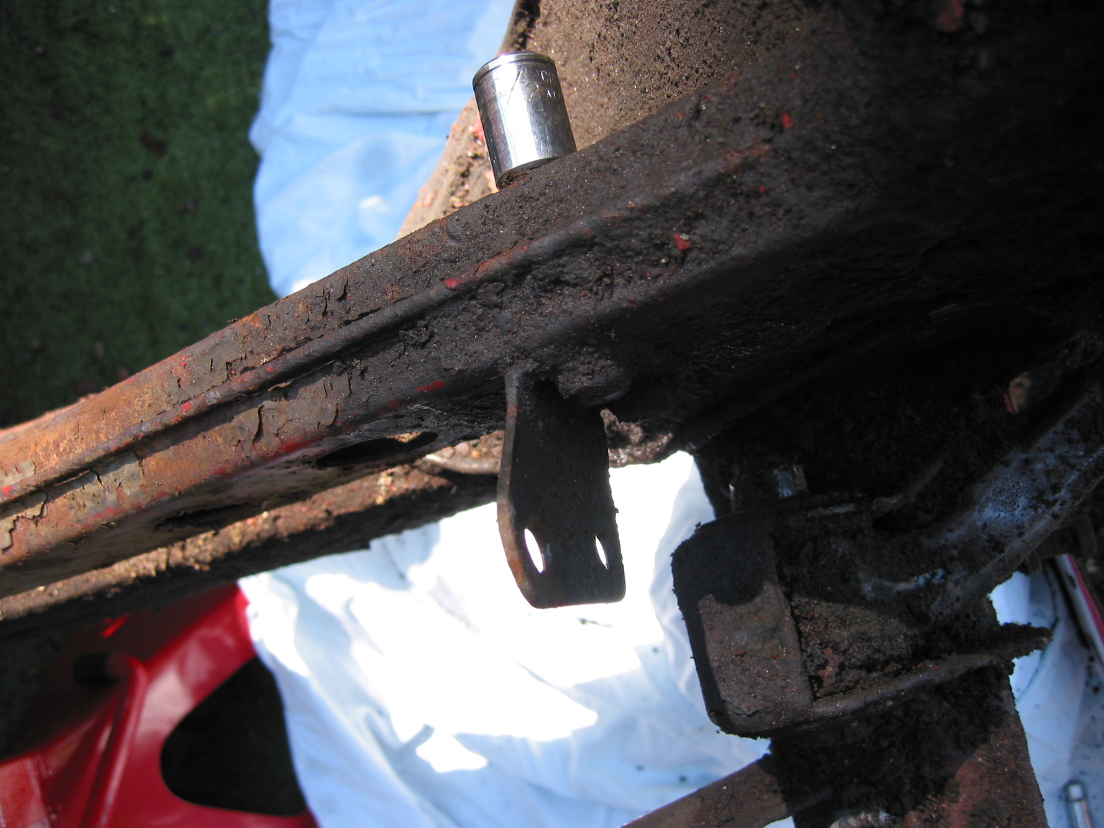
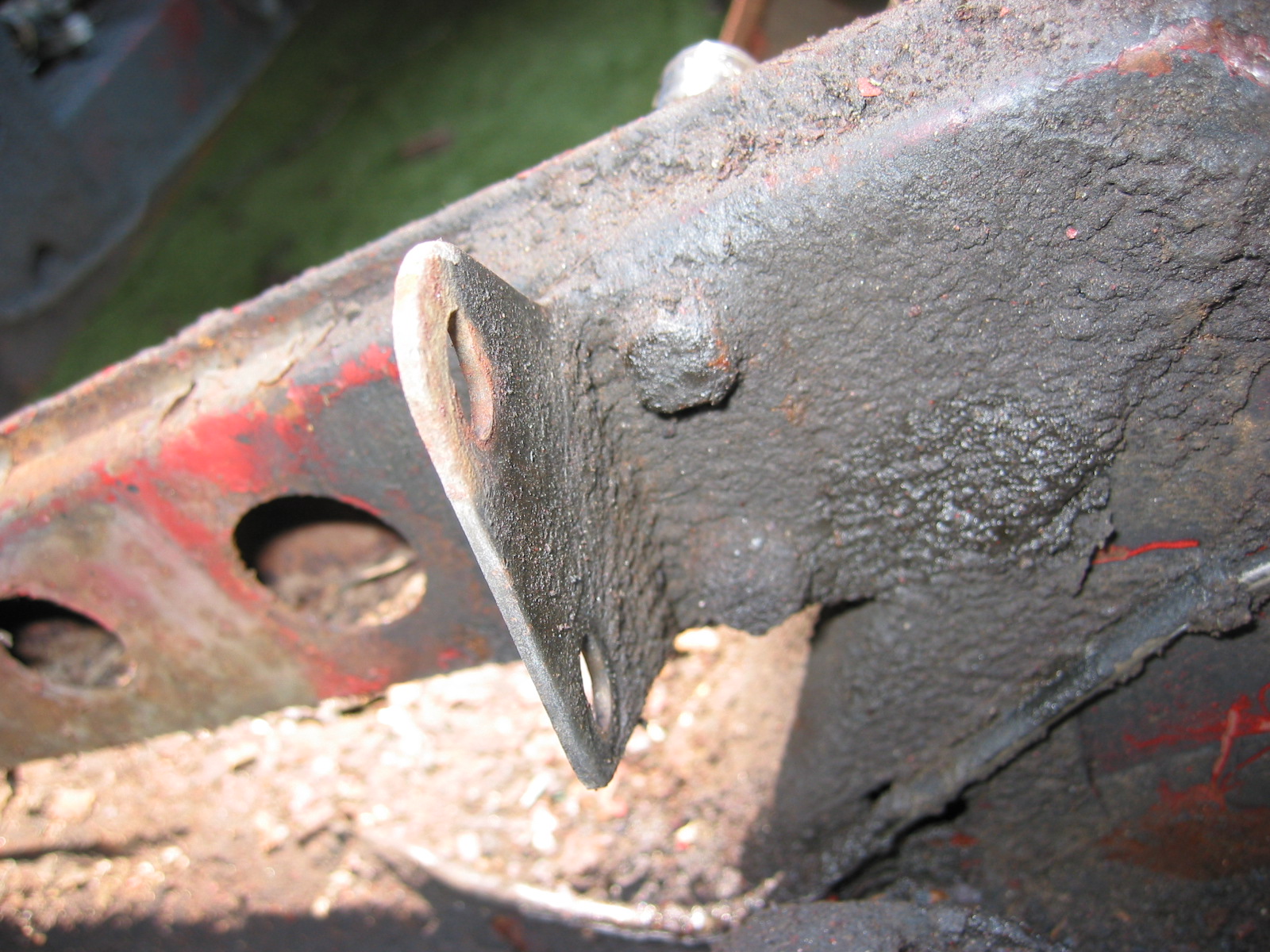
Steering Bracket 2
The radiator brackets were installed and then attention was turned to completing more of the electrical work under the dash. To protect accessory electrical functions I am adding (modern heater, accessory power supply, sound system, interior lighting, etc.), I added a supplementary fuse block mounted on the air chamber behind the dash. It was available from Victoria British, Accessory Fuse Block.pdf Painless Performance Products, #70103 Cirkit Boss/3 Circuit. A wiring diagram is available on the .pdf link. I used the pink wire to the main fuse block on the firewall, the yellow wire for the 2 speed heater, the blue wire for the amplifier, and the purple wire for the accessory power supply (cigar lighter).

Accessory Fuse Panel