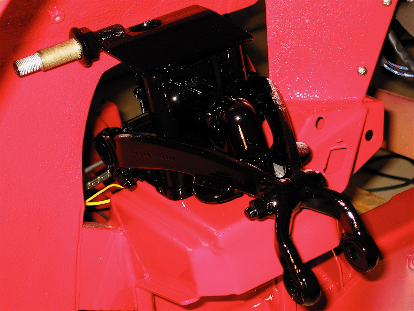
We had previously built-up the front hub assemblies including the “A” arms, stub axles, king pins, bearings, hubs, rotors, calipers and etc. This process is covered in “Front Hub Assemblies and Brakes” https://valvechatter.com/?p=13792
The “Front hub Assemblies and Brakes” post also includes a video depicting the process.
“Rebuilt Front Suspension Installed in the Car” https://valvechatter.com/?p=13828 is another post made earlier in the restoration process that is helpful to review before installing the front hub assemblies.
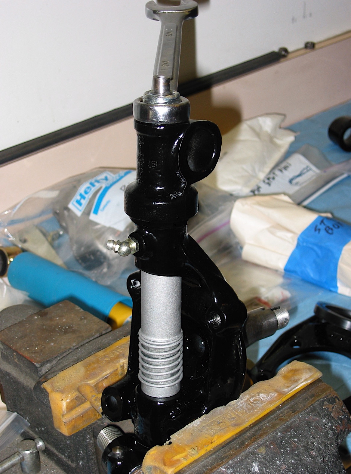
Installing these components can be approached two ways. One can assemble everything on the bench and then mount the entire assembly to the chassis as we did. Alternatively, one can mount the “A” arm and the shock absorber to the chassis and then build-out the assembly on the car. This method is the one explained in the owner’s manual.
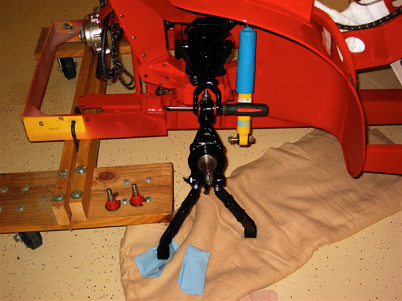
Choosing the approach we did certainly made it easier to put the various pieces together, but you end up with a pretty heavy unit that can be a bit of a struggle to mount to the chassis. Resting everything on a floor jack helps, but it is still difficult to get the holes and lower fulcrum pins lined up perfectly. At any rate the job is done.
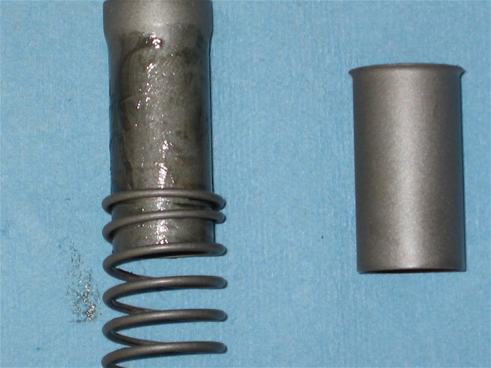
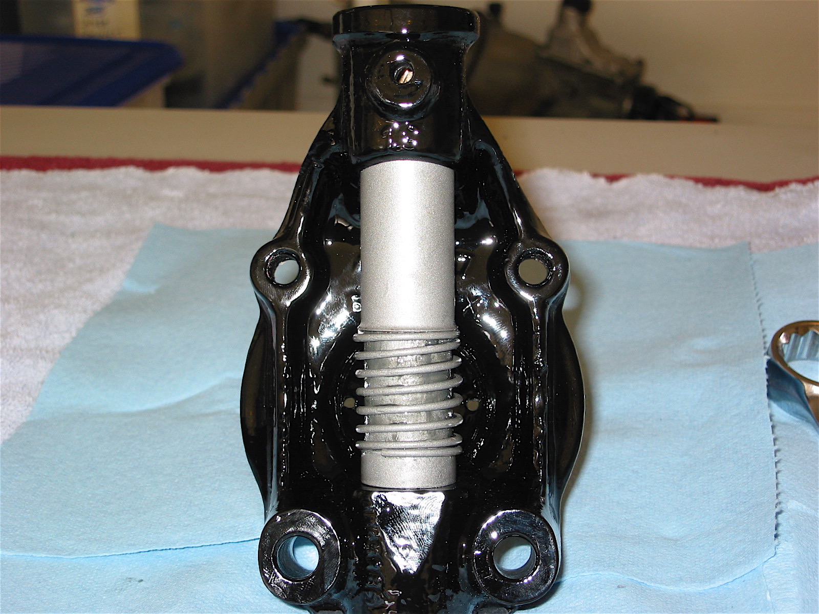
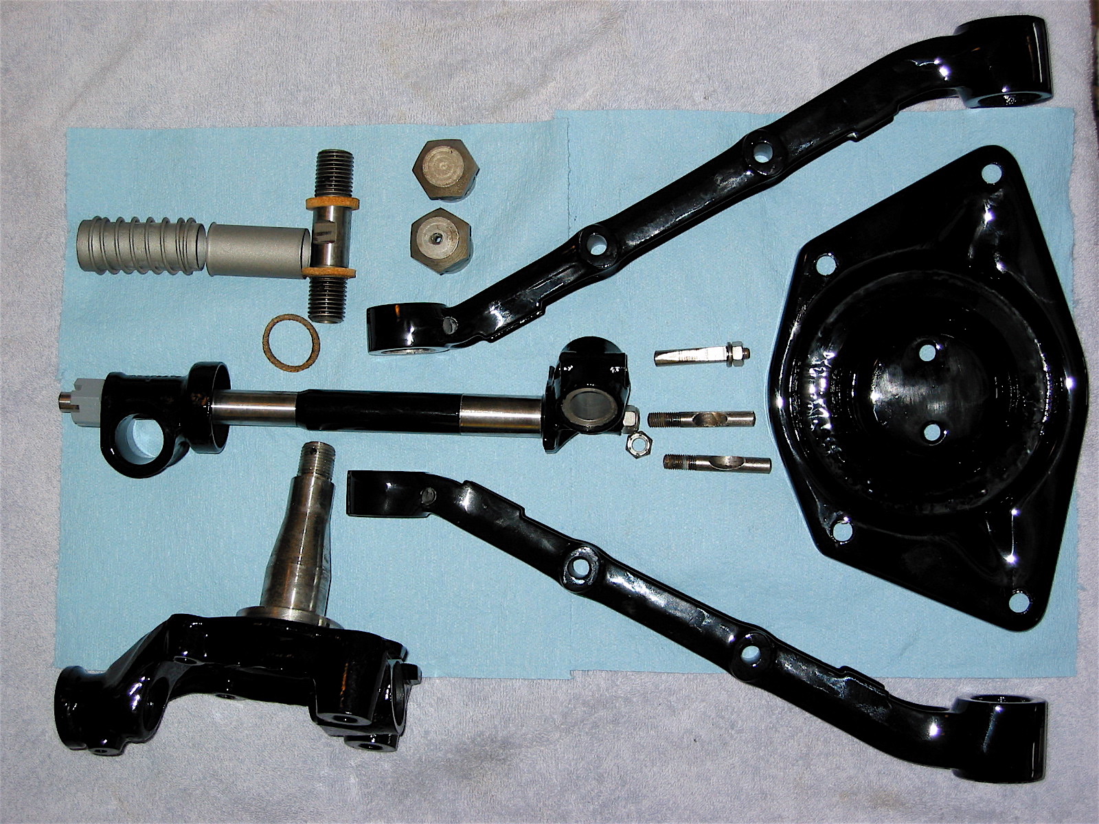
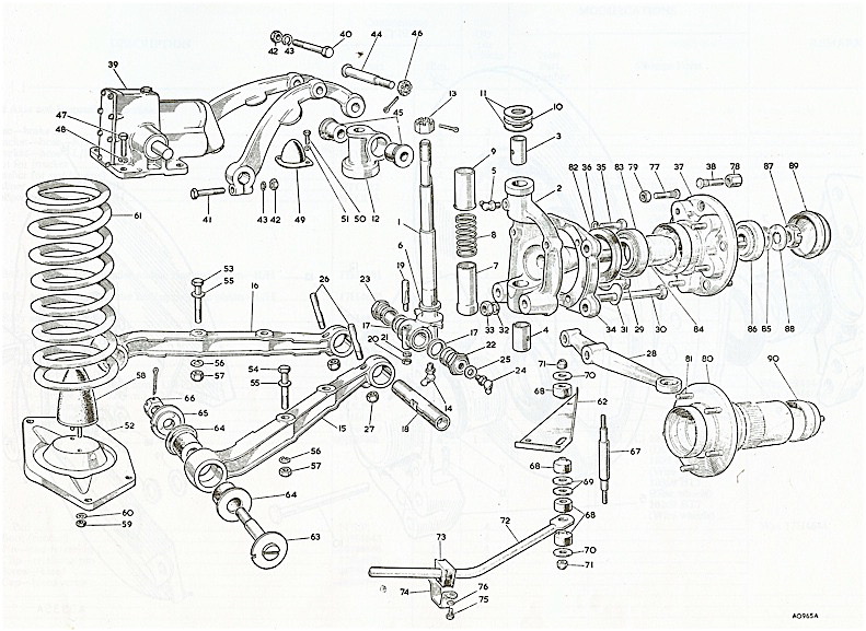
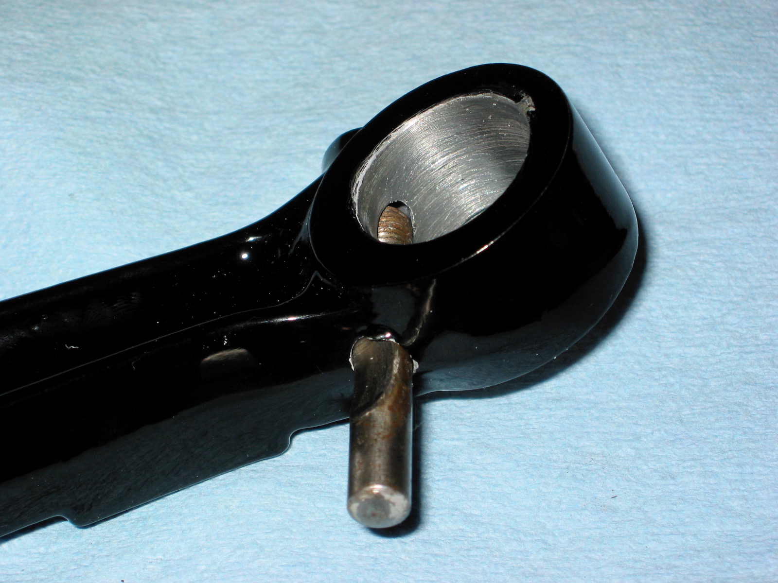
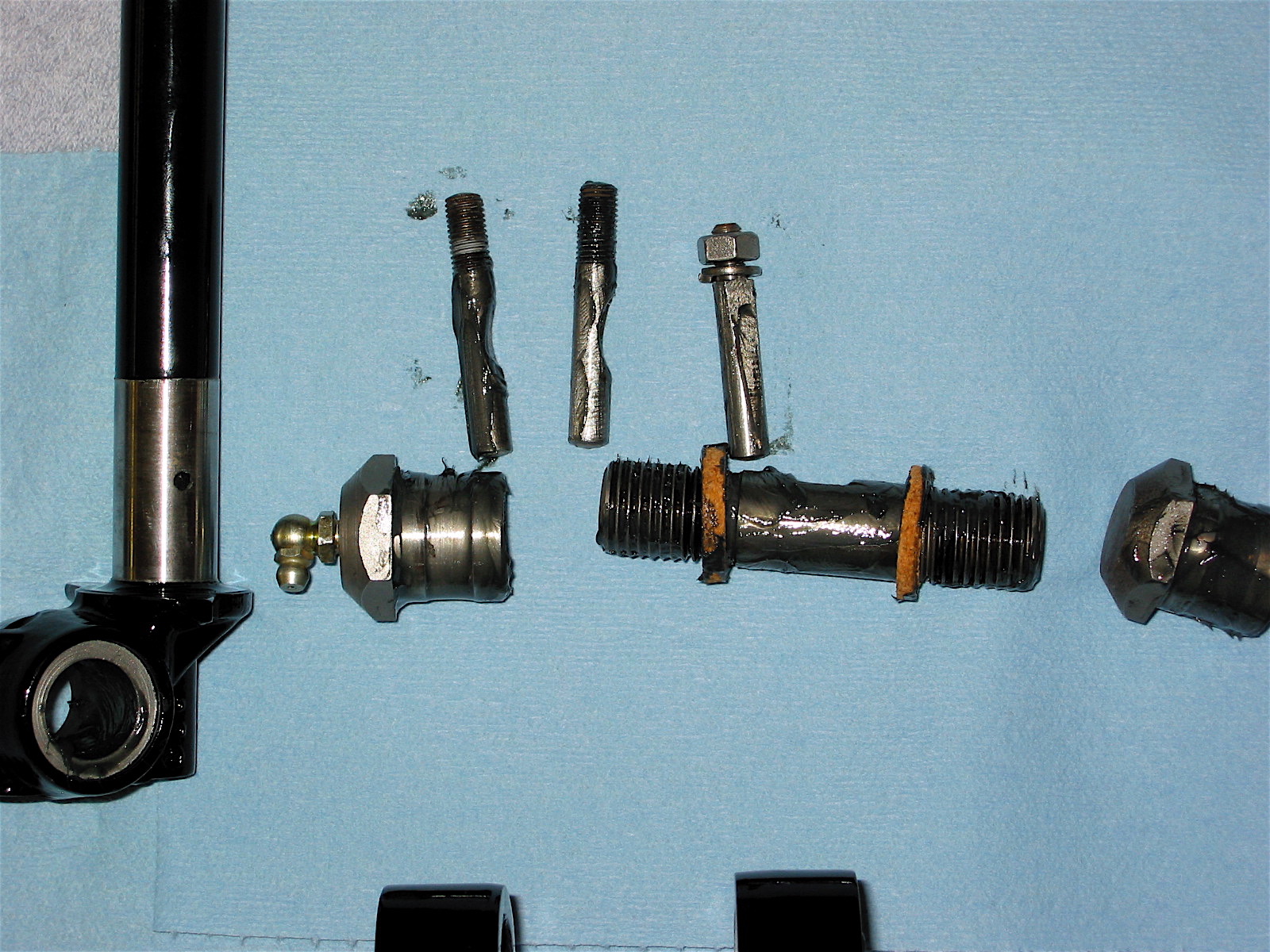
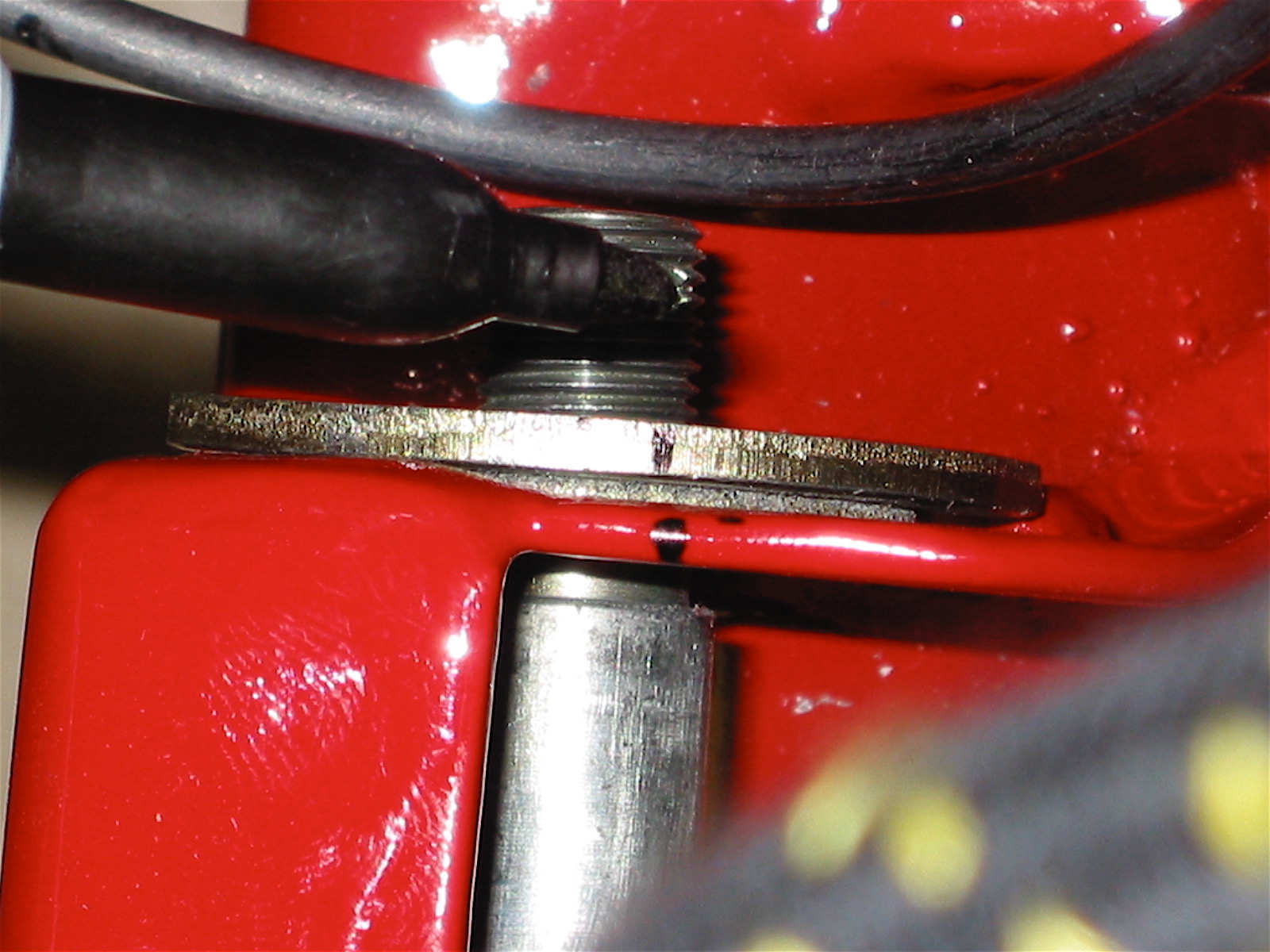
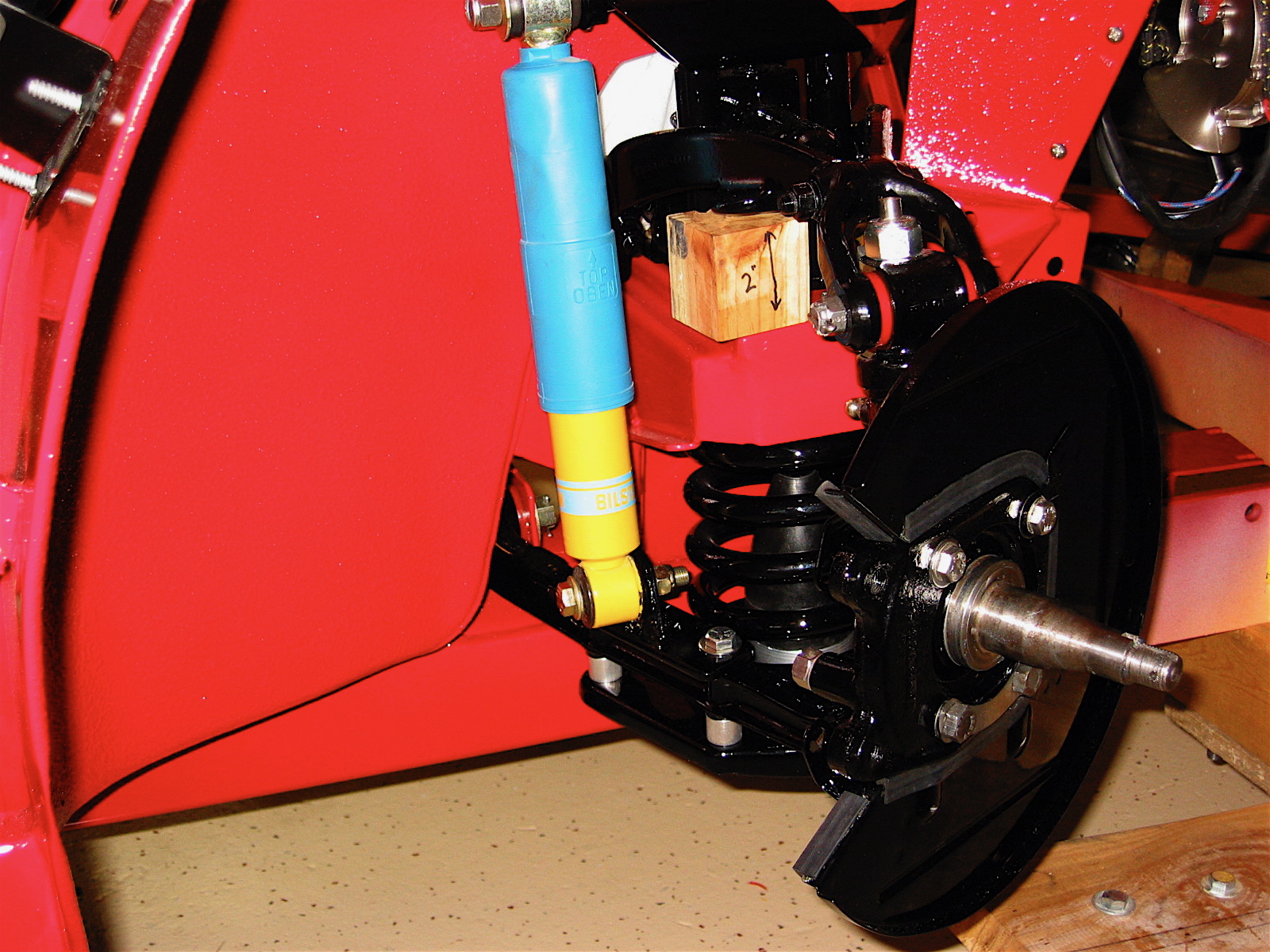
The two plates below show the various parts that are used to comprise the assemblies. Note that the lower fulcrum pins are inserted from the inside of the chassis cavity with the special washers toward the front and rear of the car. The second plate shows the earlier drum brakes while we are using later front disc brakes.
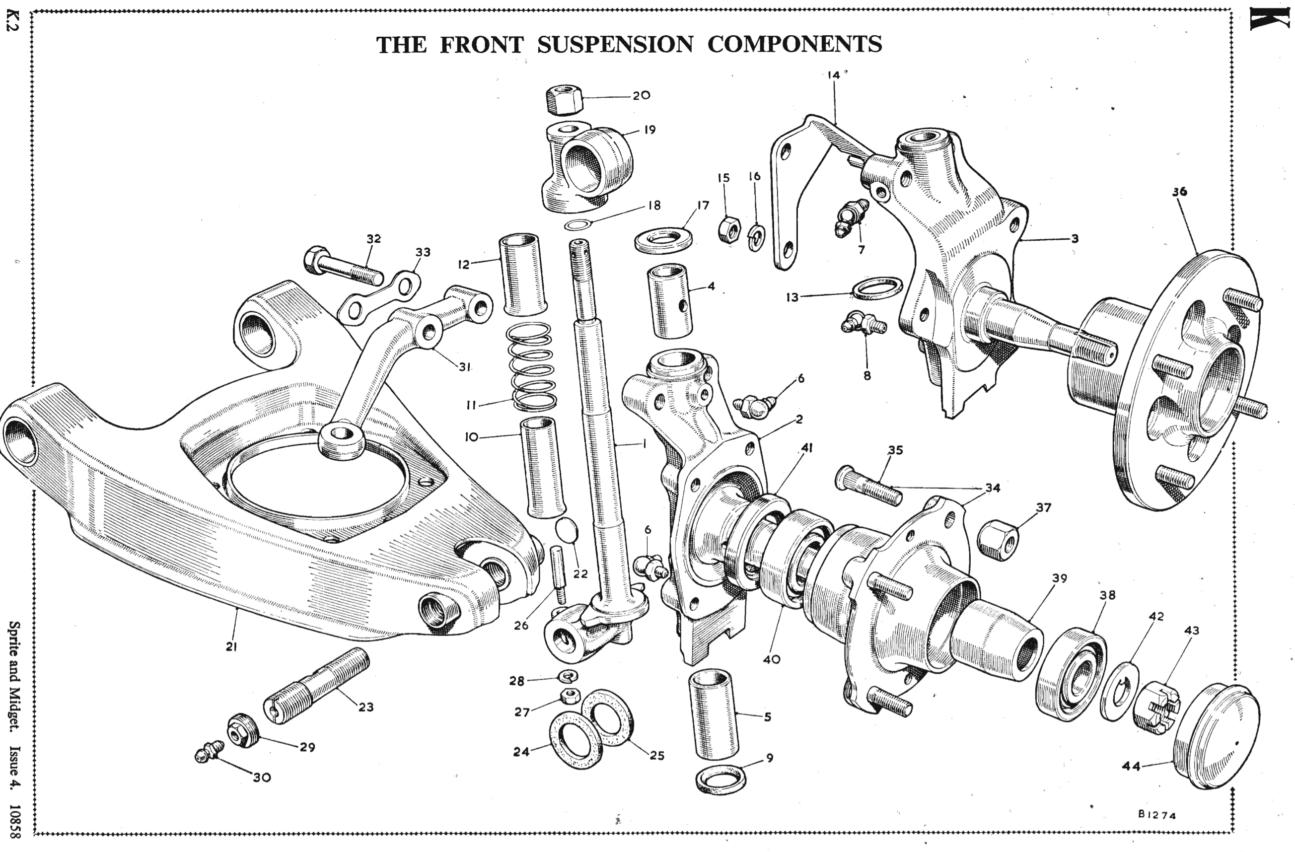
Front Suspension Components
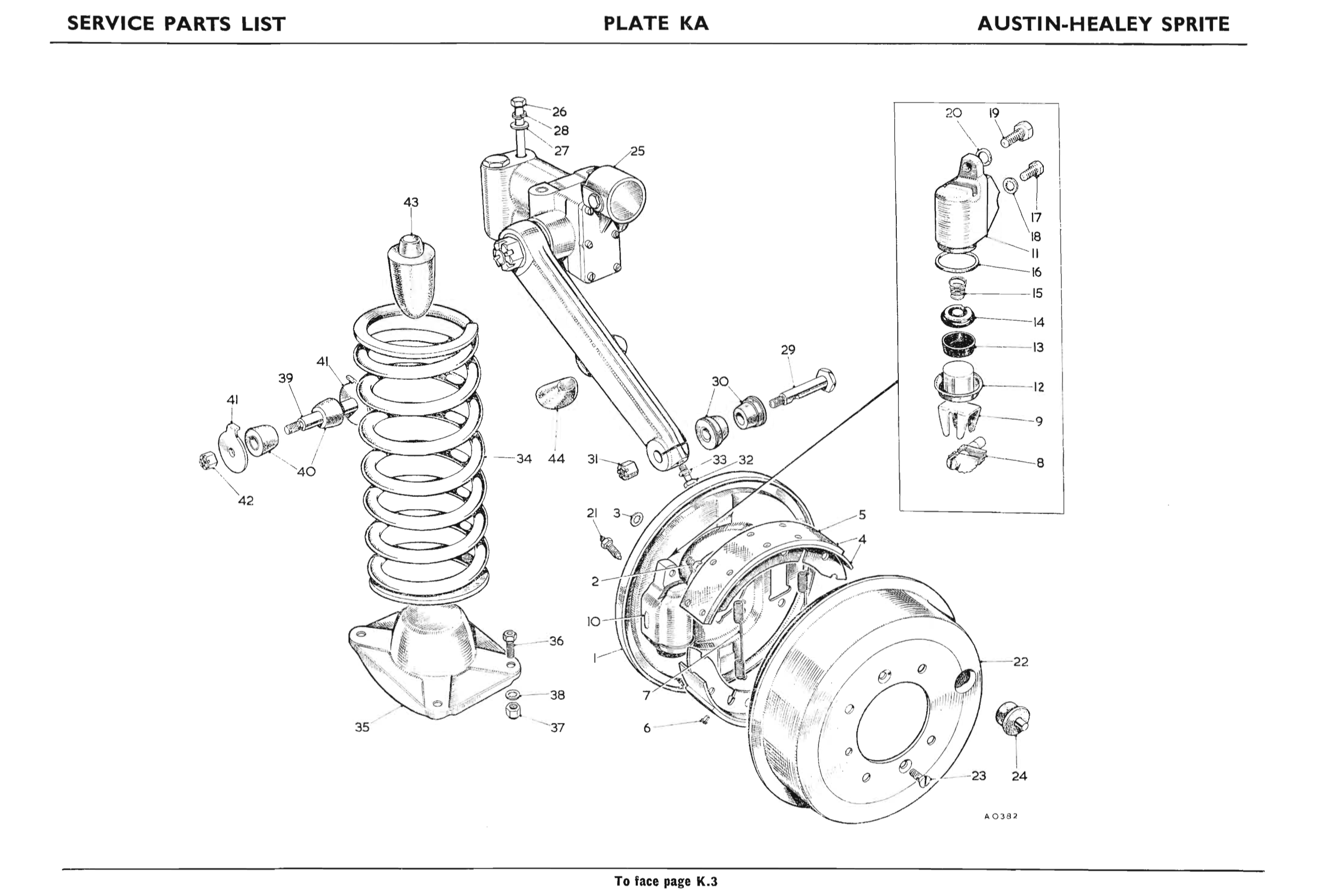
Front Suspension Components 2
Bugeye Restoration Video Episode Seventy-two shows the process of installing the completed front hub assembly to the chassis. https://vimeo.com/981964234/b1aa7a5a24?share=copy
0:00 – Front suspension hub assembly
1:07 – Installing rubber rebound buffers
1:35 – Cleaning paint from chassis mounting area to “A” arms
2:09 – Poly lubricant on fulcrum pins and bushings
2:44 – Moving the hub assembly into position
3:11 – Fulcrum pins and special washers installed
4:26 – Wood spacer blocks installed
4:56 – Upper fulcrum pin locking bolt into shock
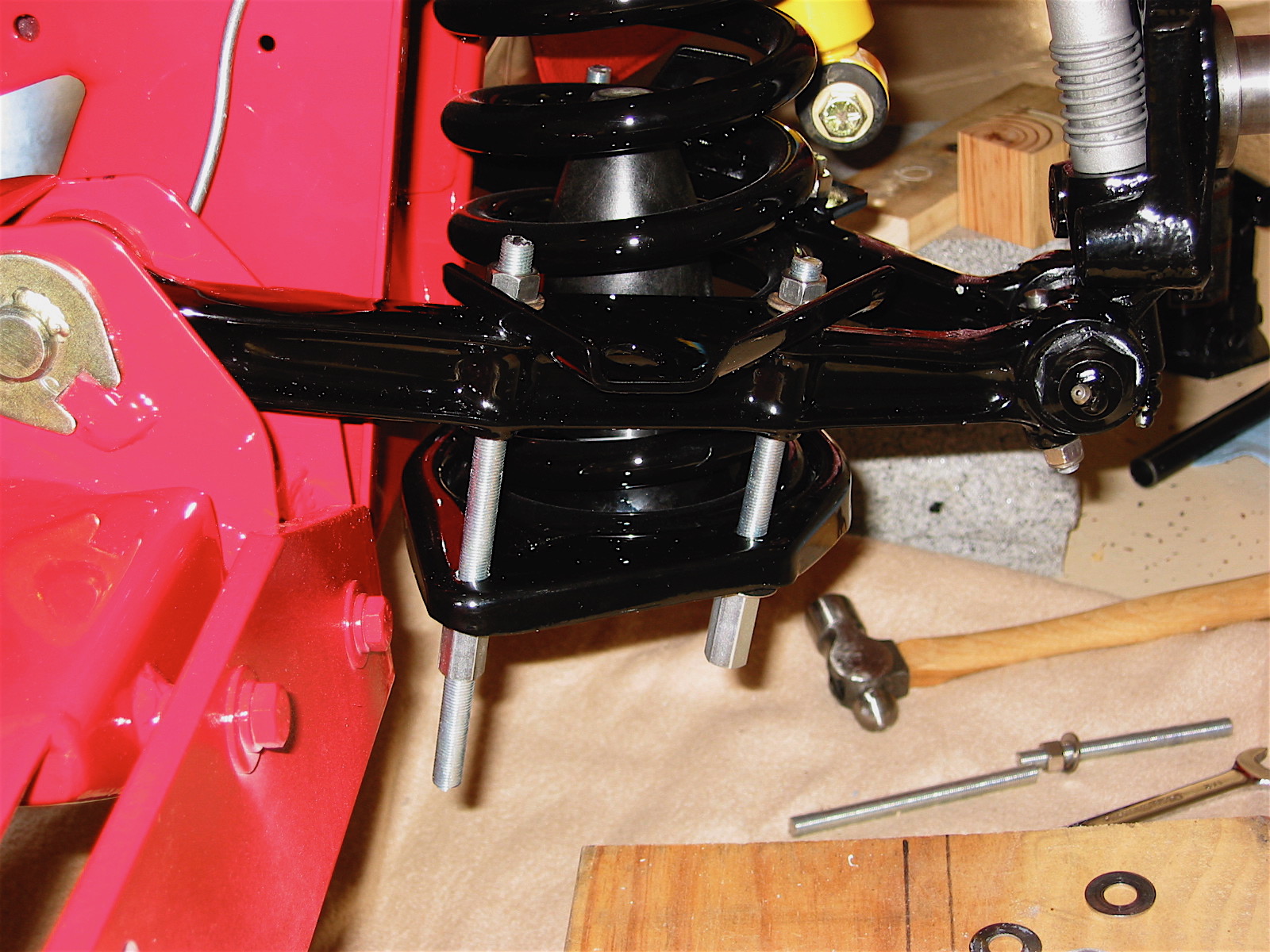
5:50 – Coil spring installation
6:30 – Coil spring installation tool
6:54 – Compressing the coil spring
The split pin on the upper fulcrum pin was then installed. All bolts and nuts were checked for tightness with the exception of the lower fulcrum pins and nuts to be tightened when the car is on the ground. A little paint touch up on a few scratches completed the process.
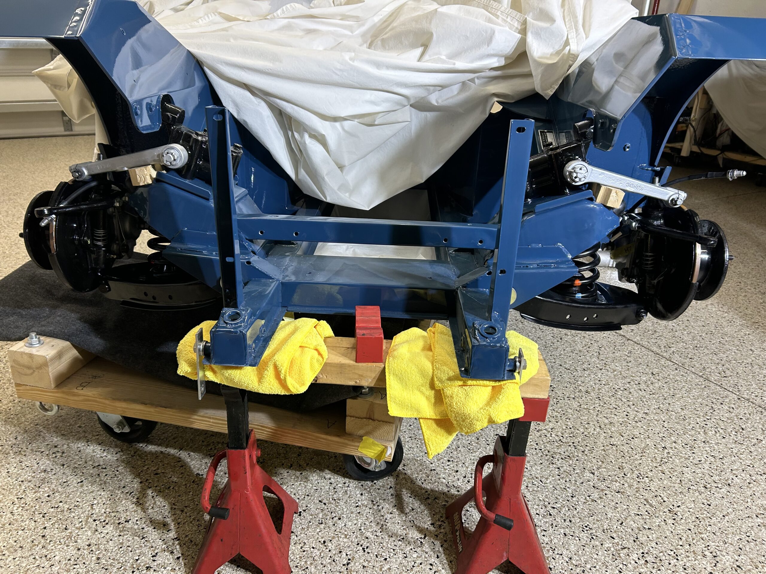
Front Hub Assemblies Installed
FRONT SUSPENSION UPDATE – FEBRUARY 20, 2025
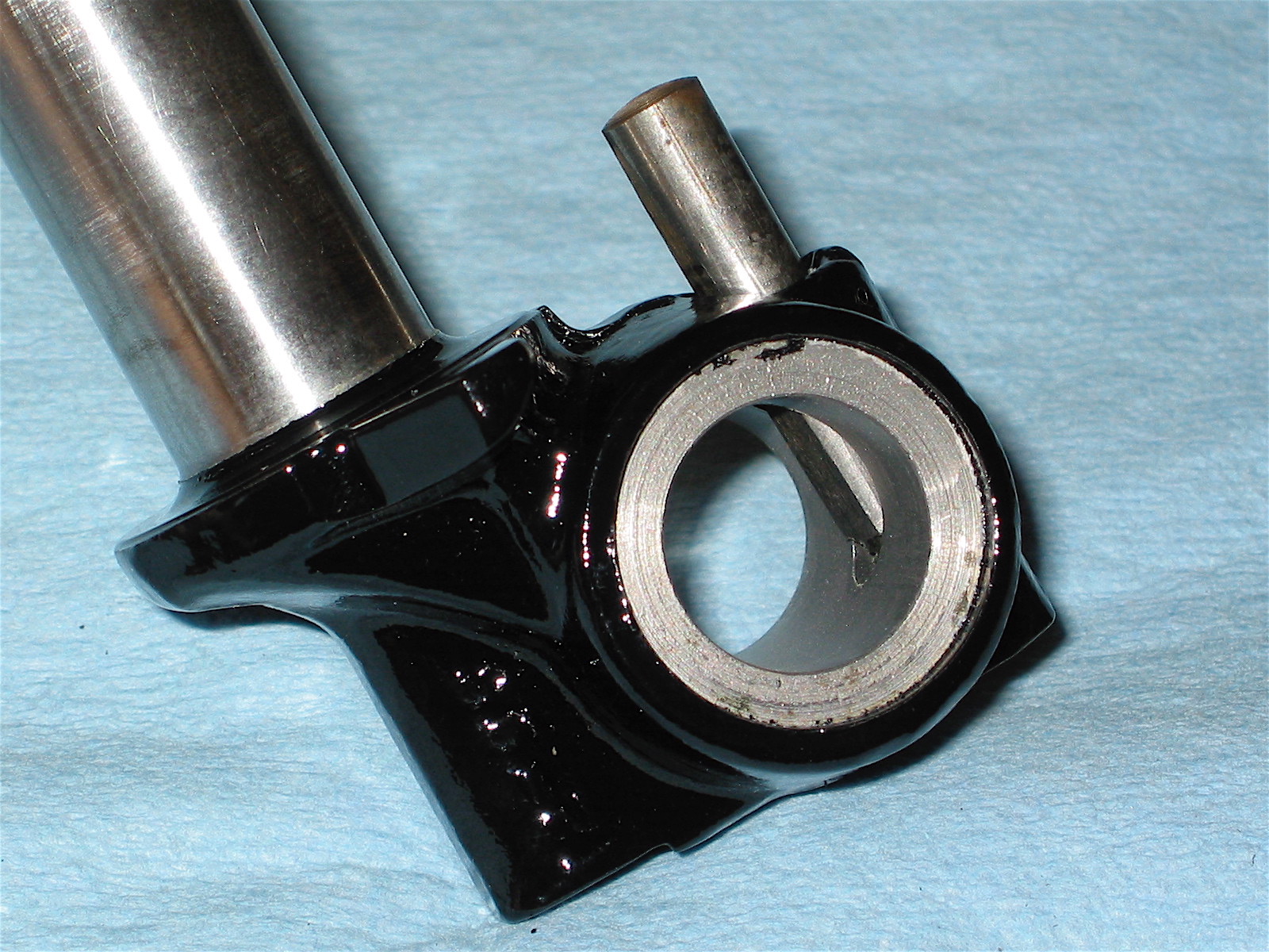
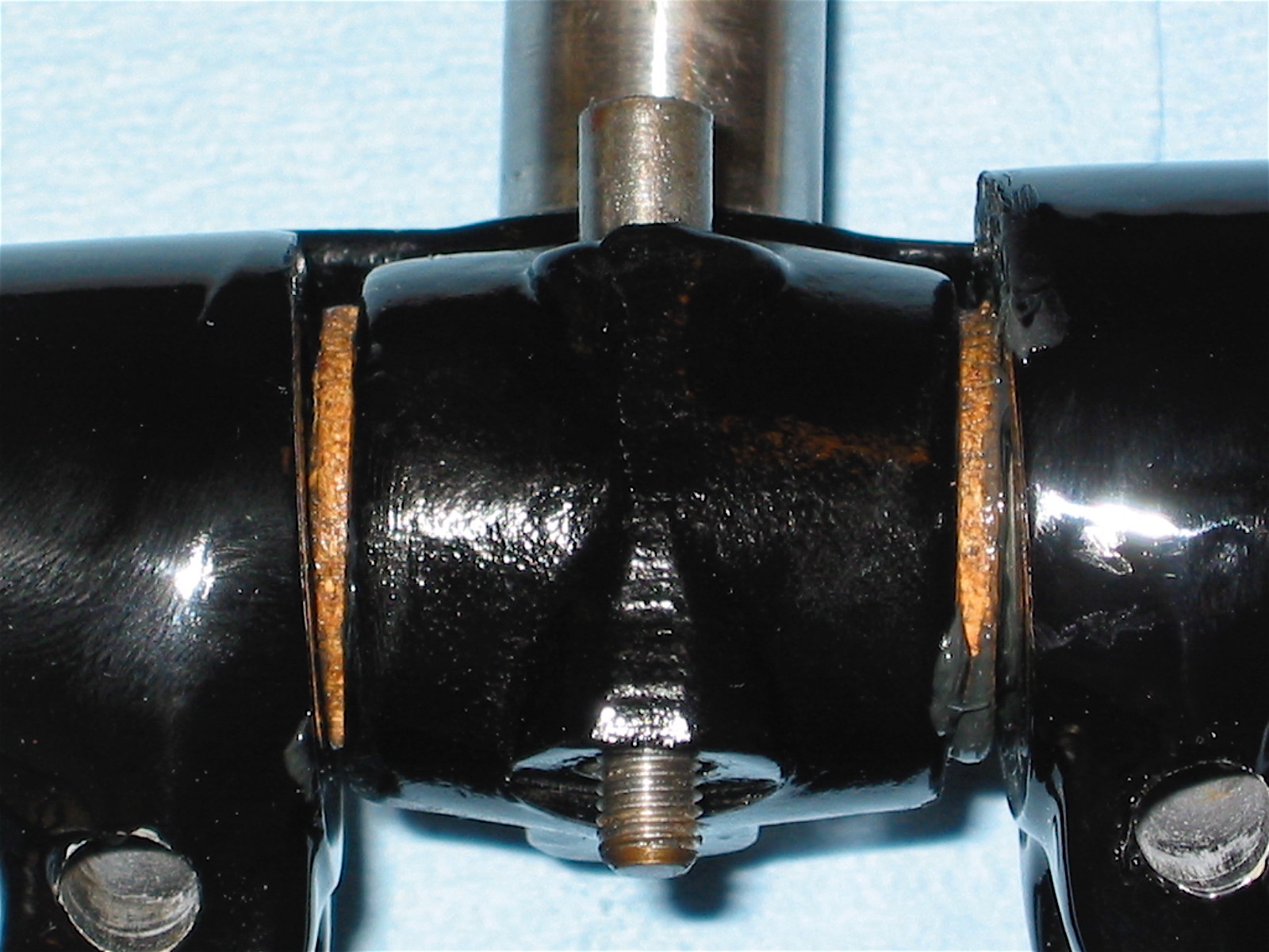
We cannot explain why it wasn’t noticed before February 2025, but on this date we discovered that one of the poly bushings on the front hub assemblies was deformed.
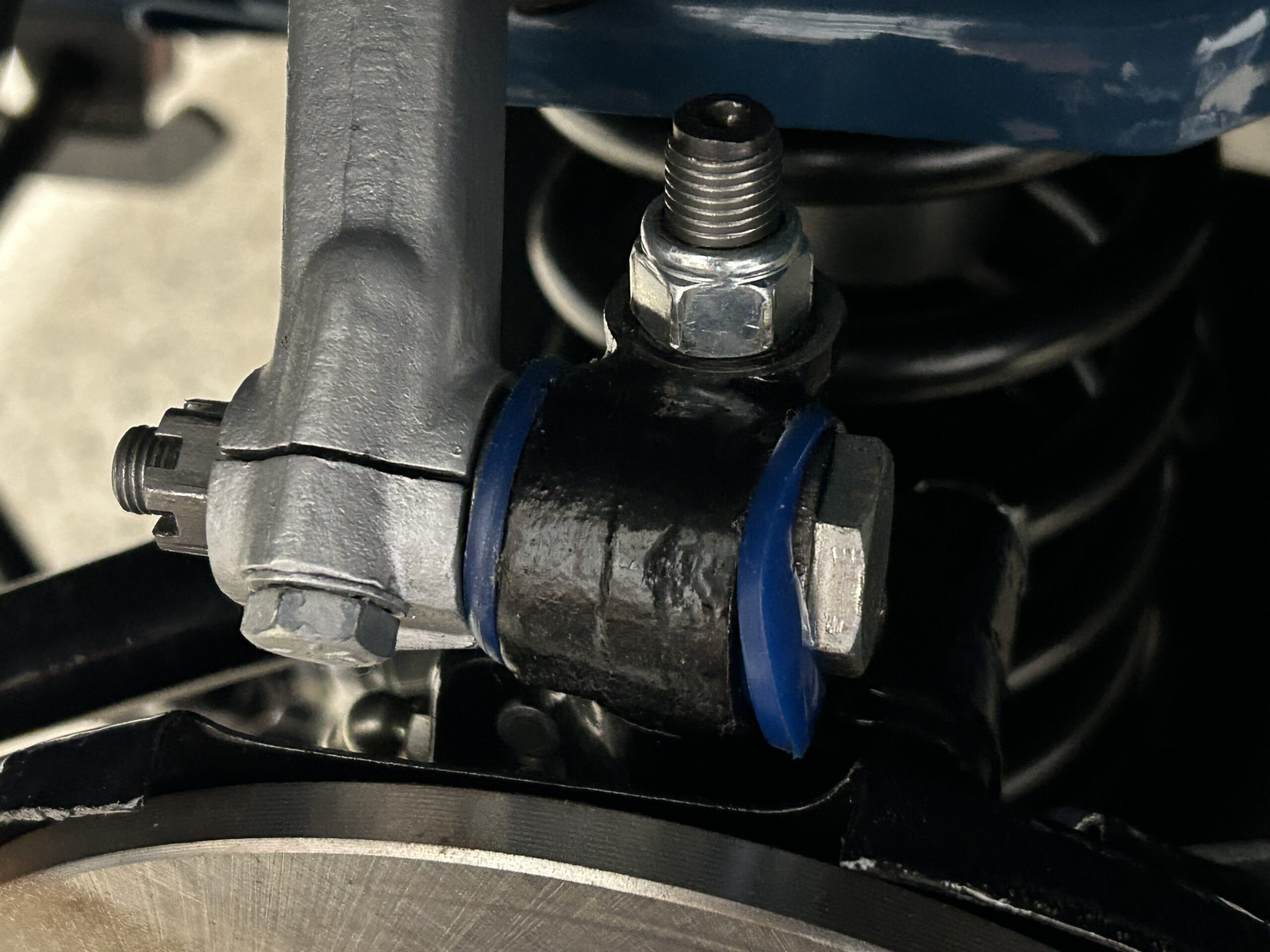
Trunnion Bushing Deformed
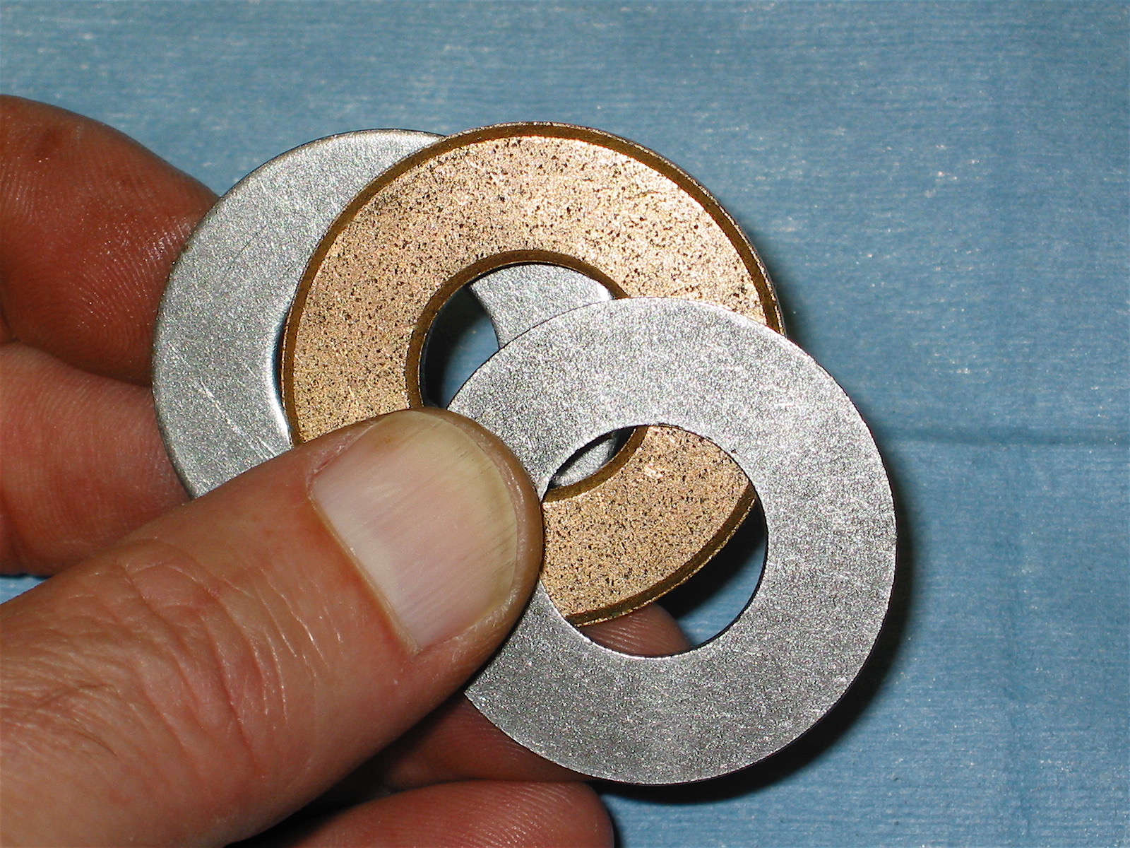
Not wanting to leave things in that state, we decided to replace the bushings. Truth be told, we are not even sure where the blue bushings came from – they may have been part of the king pin replacement kit? We ordered a set of new poly bushings made by SuperPro from Moss Motors.
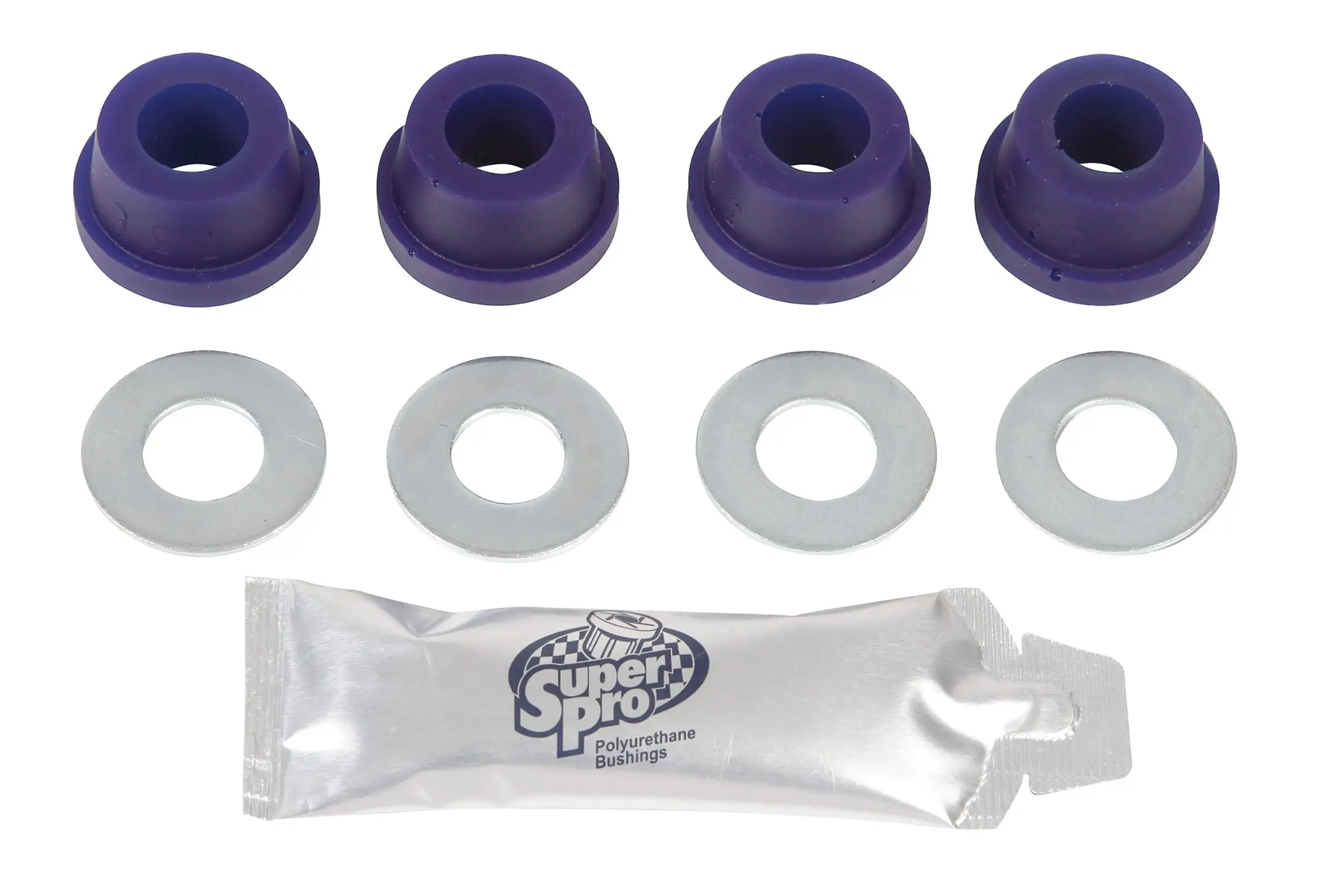
Upper Trunnion Poly Bushes
To do the replacement job safely required disconnecting the steering rod ends, and the anti-sway bar, dropping the coil springs and pulling the upper fulcrum pins. Not a particularly difficult job but one that takes a while to complete. Bugeye Restoration Video Episode Ninety-eight covers the process of replacing the bushings.
https://vimeo.com/1060562103/673c74a540?ts=0&share=copy