May 26, 2002
Wiring Harness
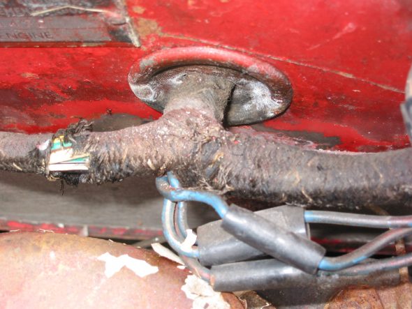
The wiring harness enters the interior cabin from a large centrally located grommet in the firewall. It splits into three strands.
Strand “A”
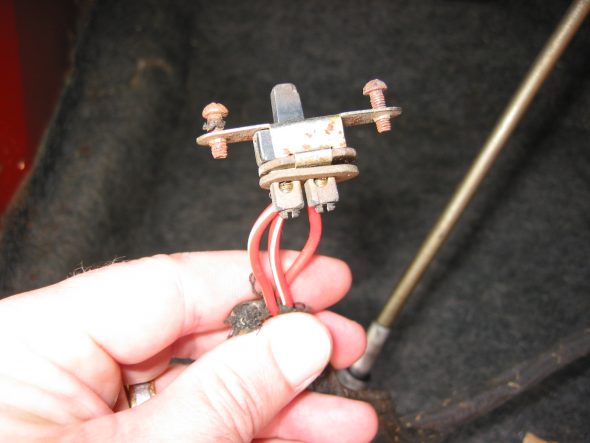
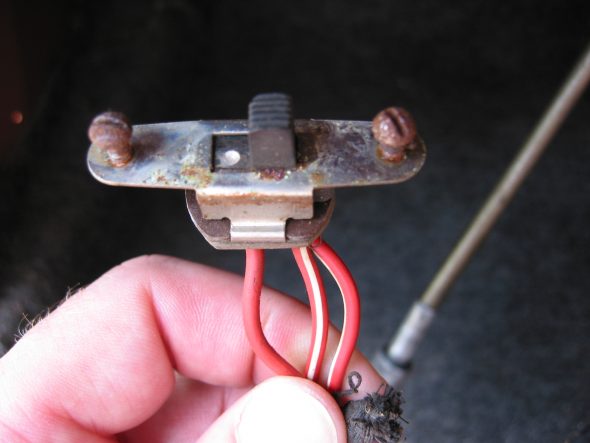
Dash panel light switch – 3 wires, 2 red/white stripe to one post. 1 solid red wire to other post.
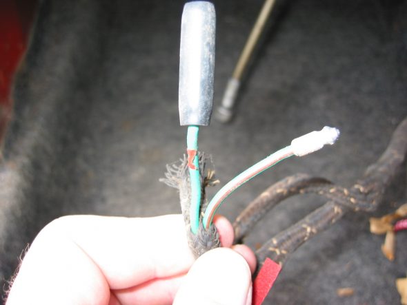
Heater – 1 solid green wire with bullet connector joint. 1 green/red stripe wire.
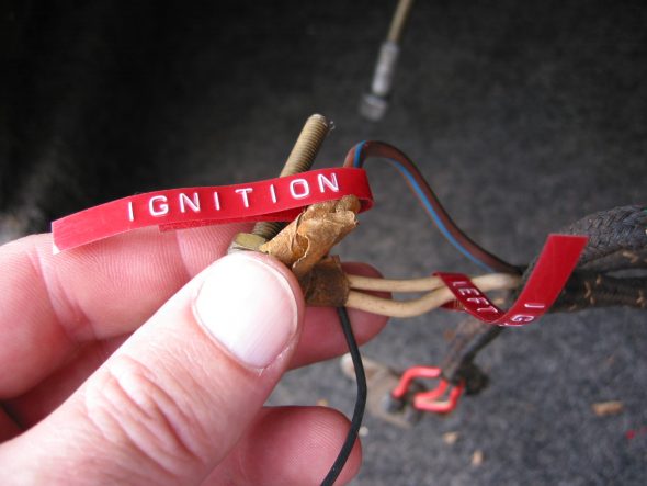
Ignition – 2 White wires to left post. 1 Brown wire/blue line to right post.
Strand “B”
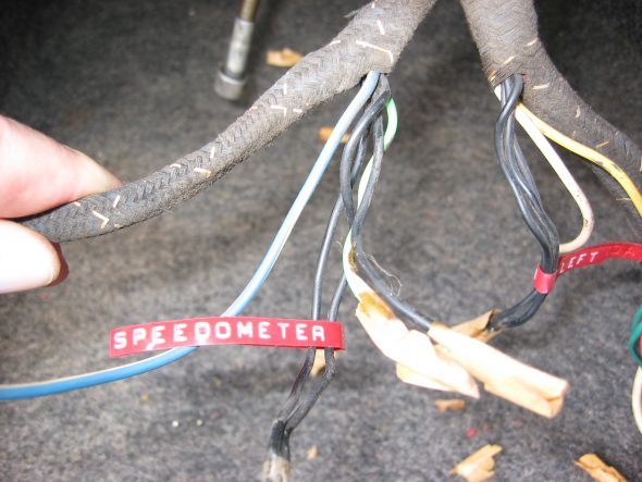
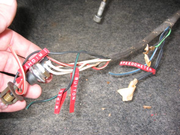
Speedometer – 2 black wires soldered to one loop connector to the right post.
1 Blue/white stripe
1 Lime green wire
1 Black wire
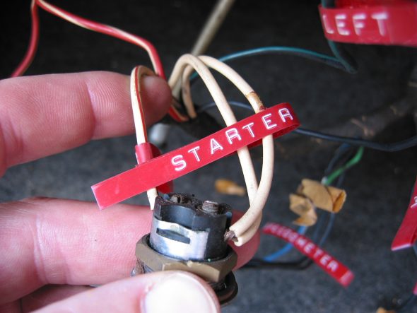
Starter Button – 2 solid white wires soldered together to right post on button.
1 white/red stripe to left post on button.
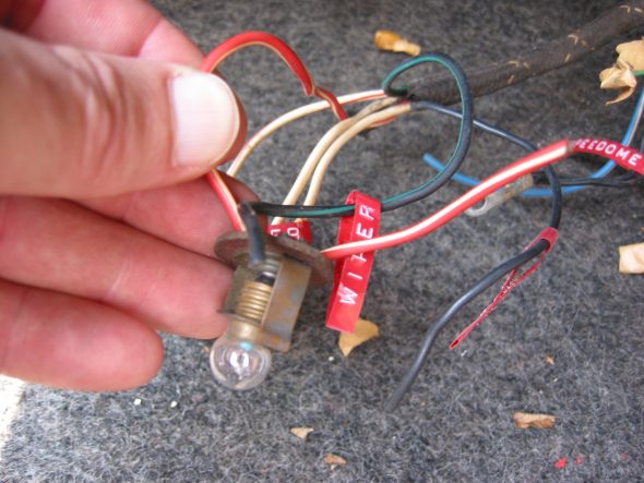
Dash Light – 1 red/white stripe wire.
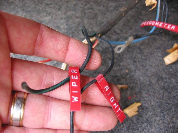
Wiper Switch – 1 black wire/green stripe to left post. 1 solid black wire to right post.
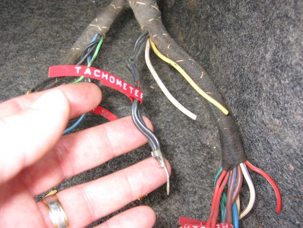
Tachometer – 3 solid black wires soldered into one connector, fasten to left post on tachometer. 1 solid white wire – ?
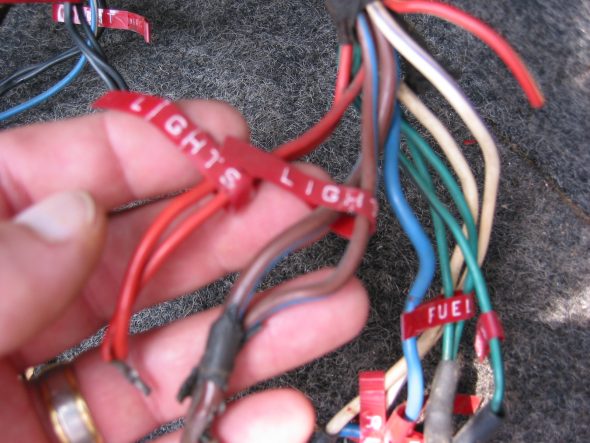
Lights – 2 red wires soldered together (1)
2 large brown wires/blue stripe soldered together. (2)
1 solid large light blue wire. (3)
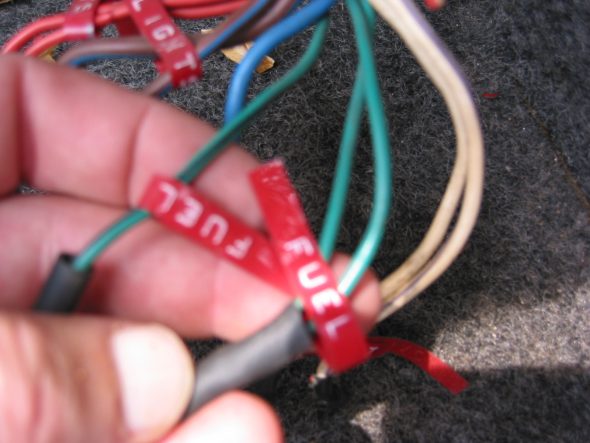
Fuel Gauge – 2 solid green wires soldered together to left post. 1 green/black stripe to right post.
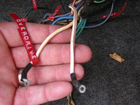
Overdrive switch – 1 solid white wire to right post. 1 white/purple stripe wire to left post.
Dash Light – 1 red wire/white stripe.

