Engine Cooling

Engine Cooling

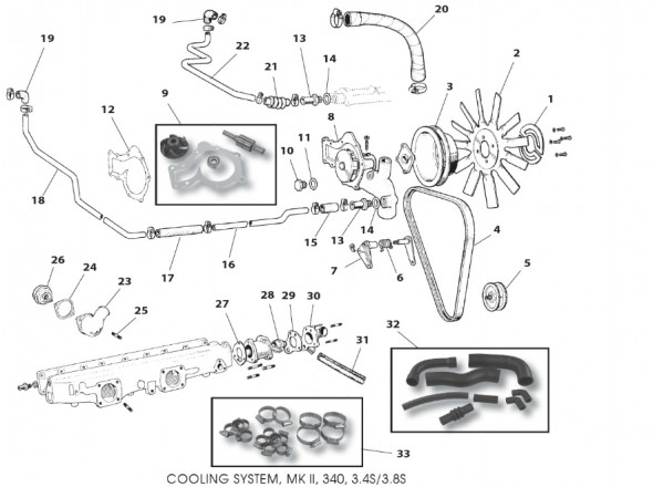
Water circulation is assisted by an impeller type pump mounted on the front cover of the engine, the system being pressurized and thermostatically controlled.


The Cooling System

The Cooling System

Water Pump and Pulley

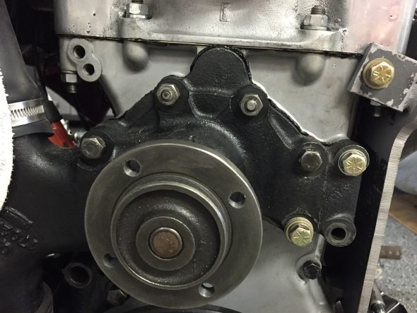
I replaced the original water pump with a new “upgraded” unit sourced from SNG Barratt.

Water Pump 

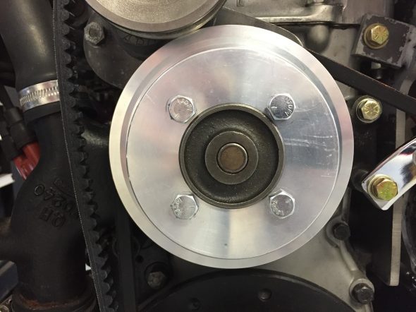
An alloy “V” belt water pump pulley was purchased with the air conditioning components from RetroAir. It measures 5.65″ in diameter and is secured to the pump with four 5/16″ – 24 x 1-1/4″ hex bolts

Water Pump Pulley

 Belt, Driving Fan

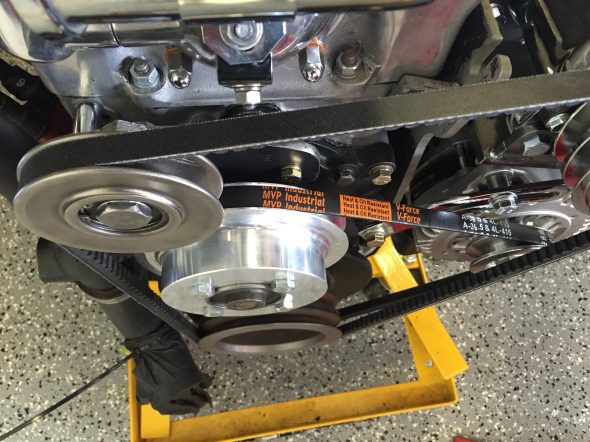
I used a 1/2″ “V” belt ordered from Advance Auto Supply. I like to get expendable items like these at a common auto supply house when possible so that if the belt breaks I can easily pick up a new one. The belt in the image below is NOT the one that I ended up using. The belt rides on the crankshaft, water pump and alternator pulleys and it is a DAYCO 17415  13A1055 that is 41.5″.

Classic half inch V Belt 39.5 Inside Measurement and 41.5 Outside

Fan

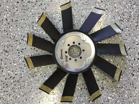
I  installed a higher performance fan than the original. I purchased it from Guy Broad in the U.K. It is some form of plastic/nylon and each blade has a greater angle to catch more air than the original. Unfortunately, I found that to accommodate the air conditioning compressor without conflict, it was necessary to trim an 1/8″ off each fan blade. This was accomplished fairly easily. I will check, and adjust if need be, the balance of the fan before final installation.

Guy Broad Fan

Guy Broad Fan

Guy Broad Fan Trimmed to Fit

Guy Broad Fan Trimmed to Fit

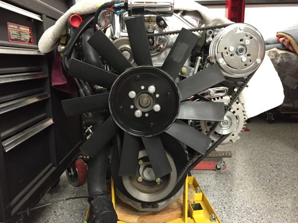
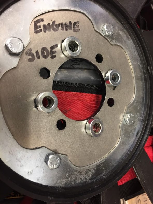
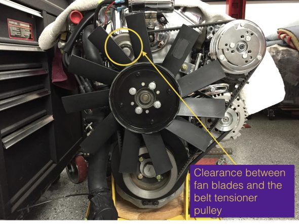
Adding the belt tensioner pulley for the air conditioning also created a clearance problem with the fan blades. I installed four 1/4″ bushings/spacers between the fan and the water pump pulley to move the fan slightly forward.I used a very small amount of dum-dum to hold the spacers in place as I mounted the fan to the water pump pulley.

Fan Spacers with dumdum

Moving the fan forward the 1/4″ did not create an issue with the radiator! Because of adding the spacers I changed the original fan mounting bolts to 5/16″ – 24 x 1 1/4″ hex head bolts with flat and shakeproof washers.

Tensioner Pulley and Fan Blade Clearance

Radiator Fan Shroud

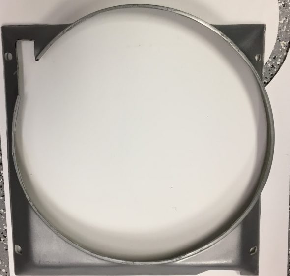
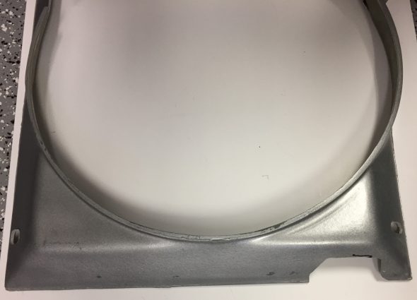
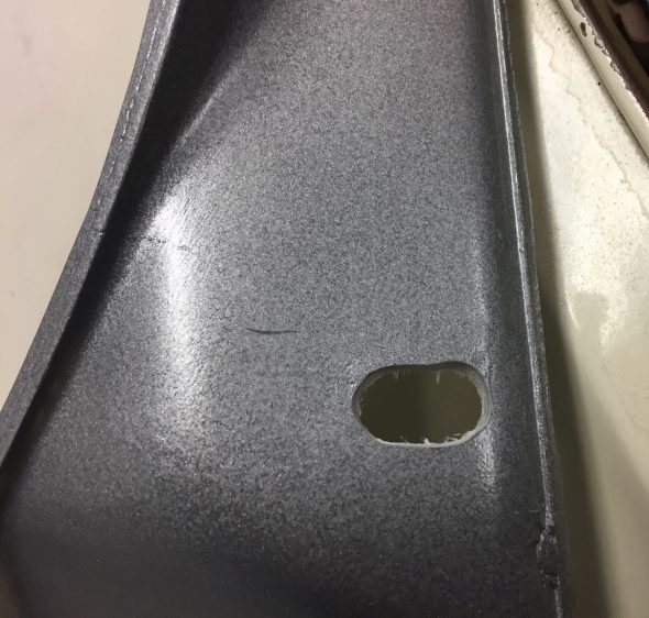
New fiberglass fan shrouds can be purchased from SNG Barratt. I found it necessary to modify the shroud slightly to provide clearance for the air conditioning compressor, the lower radiator tank  hose fitting and for the crankshaft pulley. 

Fan Shroud Opening Modification to accommodate the Sanden Compressor

Fan Shroud Opening Modification for the lower radiator hose fitting

The shroud is secured to the radiator by fastening it to four 5/16″ – 24 studs on the radiator using stainless flat washers, shakeproof washers and hex nuts. the slots cut into the shroud from the manufacturer were not sufficiently large to fit properly so each of the four mounting holes was somewhat enlarged using a dremel tool.

Enlarged Fan Shroud Mounting Holes

After a trial fitting of the shroud I found that I did not like the original silver/grey color of the shroud and painted it gloss black to match the upper radiator tank.

Radiator

I had chosen to replace the original radiator with an aluminum unit made by Wizard to improve cooling and assist with the air conditioning system. I purchased the radiator from RetroAir with my other air conditioning components. It looked beautiful!

I ended up not using the Wizard unit because it did not fit properly. It sat too high, contacting the bonnet, and because of the wider upper tank it did not allow sufficient space for the wiring harness that travels across the front of the radiator from the LH valance to the RH valance. A sad and expensive lesson. I could have modified the aluminum unit to fit but could not solve the wiring harness problem to my satisfaction.

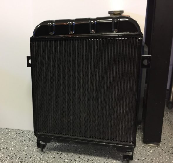
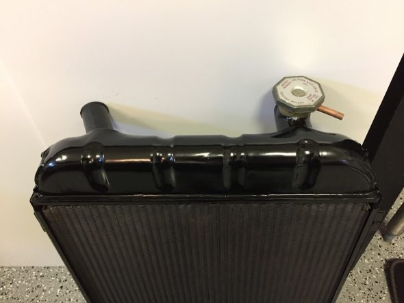
I decided to return to my original radiator but had it recored by Blue Sky Radiator with a modern cooling matrix. I painted the sides of the assembly and the lower tank with POR-15 after using their metal prep product. I then used progressively finer sandpaper to prepare the upper tank surface and then painted it with a Duplicolor self etching primer (three coats) and Duplicolor Engine High Temperature Gloss Black spray paint (also three coats). I just lightly dusted the front of the core with the high temperature paint as I wanted to avoid affecting the heat radiation properties of the radiator to the extent possible. I did not paint the rear face of the core. I was pleased with the results:

Painted and Recored Original Radiator

Painted and Recored Original Radiator

Installing the Radiator and Shroud

After the fan is mounted to the water pump pulley, it is necessary to loosely position the shroud over and behind the fan.

Fan Shroud in Position for Radiator Install

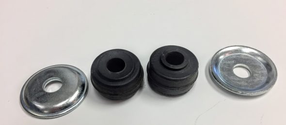
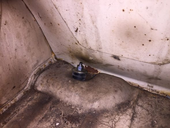
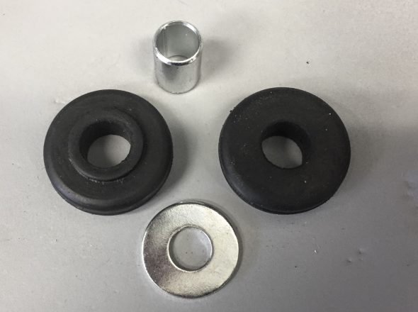
LH and RH rubber pads and distance tubes for mounting the radiator block to the car need to be located in the mounting holes in the frame.

Radiator Mounting Rubber Pads, Distance Tubes, and special washers

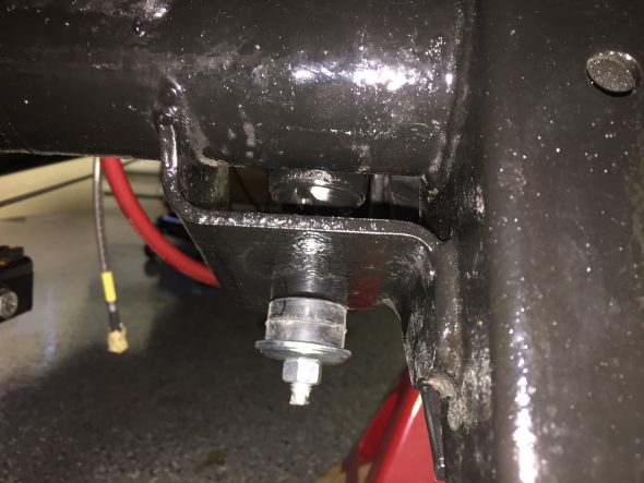
One can then carefully manipulate (not quite as easy as it sounds) the radiator downward as the fan blade is turned by hand. The radiator lower mounting studs need to fit into the rubber pads and distance tubes and then through the frame. Once the radiator is in place, another rubber pad, the special washer and a 3/8″ nylock nut can be loosely secured to the mounting stud. The shoulders on the rubber pads need to face the hole in the frame.

Rubber Pad, Distance Tube, Special Washer and 3/8″ Nylock Nut Lower Radiator Mount

Once the lower mounting hardware is fastened, the two upper mounts on the LH and RH sides of radiator can be secured using the special 3/8″ – 24 bolts, rubber pads and distance tubes. I had cleaned these special purpose bolts and had them zinc plated.

With the four radiator mounting points all secured, the fan shroud can then be mounted to the four radiator studs using flat and shakeproof washers with 5/16″-24 hex head nuts. I then back-tracked and tightened down all the fittings.

Both the upper and lower radiator hoses can then be fitted to the radiator and Jubilee Clips tightened.

Hose from Bottom of Radiator Block to Water Pump with Size 2A Jubilee hose clip

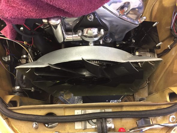
The images below show the radiator assembly with the black fan shroud mounted in the car:

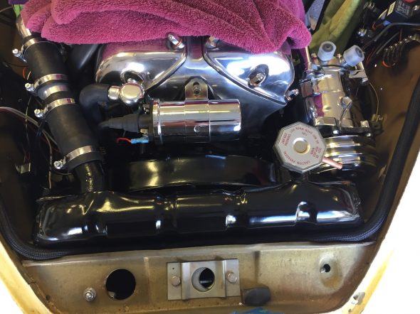
Radiator, Fan Shroud and Upper Hose in Place

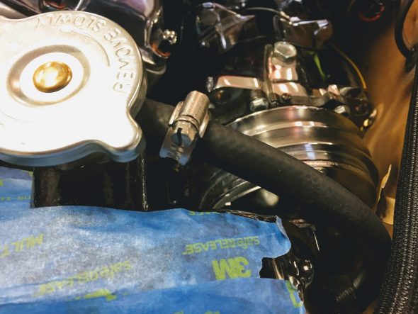
As can be seen in the image above, Jaguar provided an overflow outlet from the radiator neck. I attached and clamped a 5/16″ drain hose from the outlet. For the moment I have it draining to the ground as I am not sure if it will be needed. I plan to use Evans Waterless Coolant in my car. The Evans product supposedly produces very little pressure. This is a subject I will address in greater detail later. Should I find that the drain is needed I will find a place SOMEWHERE for a collector bottle. The image below shows the drain hose and clamp used.

Radiator Coolant 5/16″ Drain Hose

Radiator Drain Tap

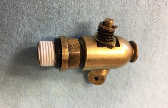
I disassembled the brass drain tap and after cleaning and lubricating I reinstalled it in the refurbished radiator. I did not have a fabric washer that fit so I used a rubber “O” ring. The drain tap is not installed in the radiator until AFTER the radiator is mounted in the car. Otherwise it becomes an obstacle in mounting the radiator.

Drain Tap for Radiator Block with rubber O ring

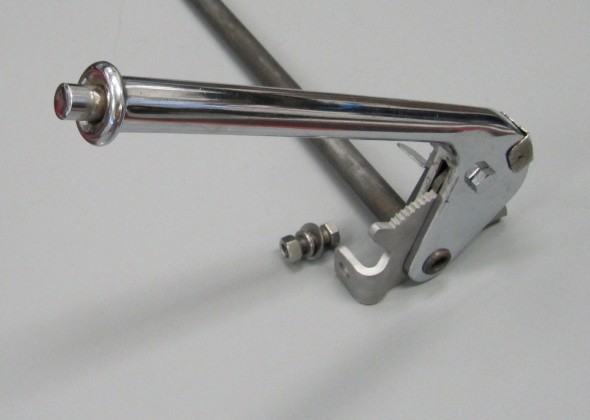
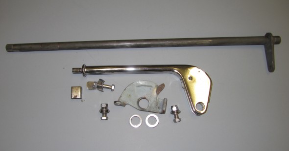
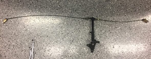
As originally configured, Jaguar provided a proper remote control for the drain tap, allowing the owner to open the drain valve by simply turning the control rod rather than crawling under the car. See the image below. Unfortunately, I am unable to use this control rod because its mounting bracket contacts the air conditioning compressor. I will just have to crawl under the car an operate the drain tap by hand!
control-rod-assembly-operating-drain-tap-1


Hoses and Temperature Sender

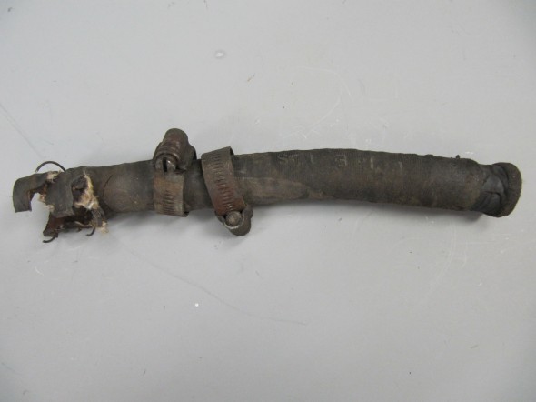
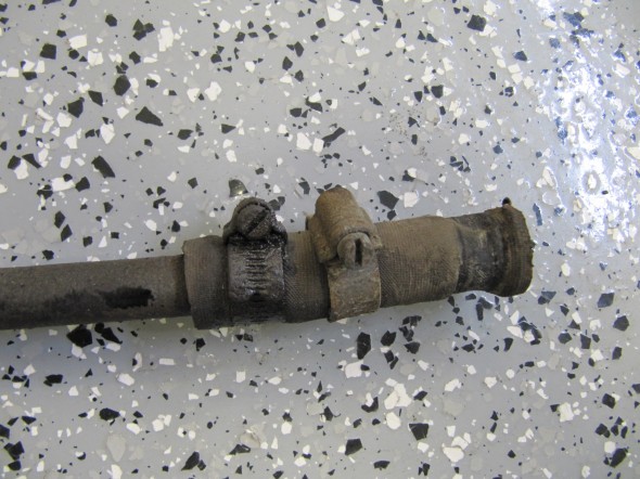
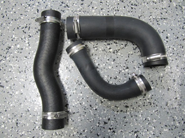
I replaced all rubber in the car including the heater and engine cooling hoses. Here are the three primary coolant hoses with new Jubilee clamps. The top water hose, from radiator block to water pump, the hose from the bottom of radiator block to water pump, and the by-pass water hose.

Primary Coolant Hoses

Primary Coolant Hoses

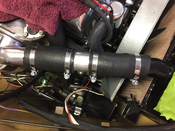
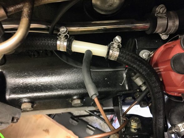
I debated for some time about where to install the water temperature sending unit to control the operation of the electric fan. These are typically placed in the engine, on the lower radiator tank, the upper radiator tank, or in an especially designed coupler inserted into the upper radiator hose. I decided against modifying the original radiator and ultimately chose to use a hose coupler. I cut the upper 1-1/2″ hose and inserted the coupler. The clamps are 32-50mm.

Fan Thermo Switch in Hose Coupler

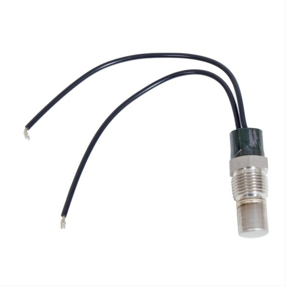
I used a SPAL Automotive USA IX-185-2TS Fan Sending Unit purchased from Summit Racing Equipment https://www.summitracing.com/search?SortBy=BestKeywordMatch&SortOrder=Ascending&keyword=SPU-IX-1852TS.  It threads into the coupler with a 3/8″-18 NPT thread and turns off at 165 degrees F., and turns on at 185 degrees F. I liked this switch because it has a separate wire to ground rather than relying on the body of the switch for ground. The aluminum coupler was purchased on ebay: Radiator Sensor Tube Adapter Water temperature Gauge 1-1/2″ OD 3/8″ NPT (141025992422).

SPAL Thermo Switch

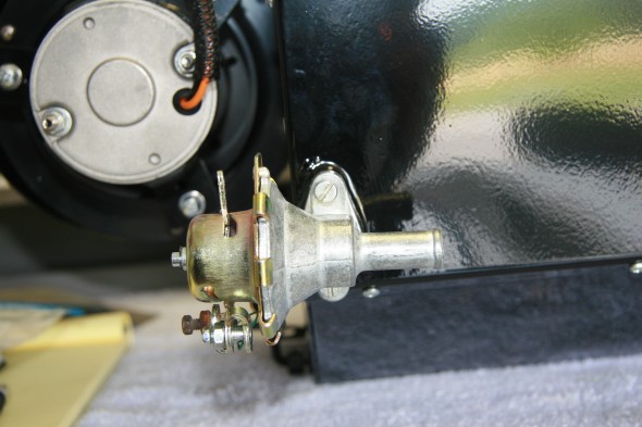
The Adaptor, In Inlet Manifold, For Water Feed to Heater Unit

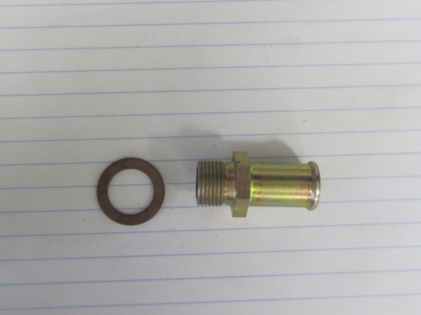
The original Adaptor, In Inlet Manifold, For Water Feed to Heater Unit was corroded badly, so I replaced the adaptor with a new one sourced from SNG Barratt, including a new fiber washer.

Adaptor In Inlet Manifold for Water Feed to Heater Unit

Adaptor In Inlet Manifold for Water Feed to Heater Unit

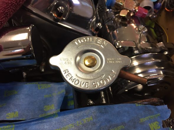
Radiator Cap

The MK2 used a 4 lb. cap originally and may have gone to a 7 lb. cap later in production. I am not sure. I sourced a new 7 lb. cap from M&C Wilkinson in the U.K. for my MK2. It is important to get the proper length cap so as to achieve the right seal in the radiator neck.

7 lb. Radiator Cap


Heater

Heater

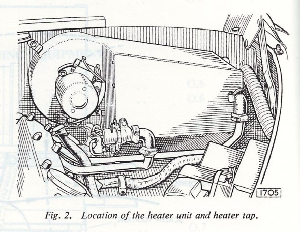
The heating and ventilating equipment consists of a heating element and an electrically driven fan mounted on the engine side of the scuttle. Air from the heater unit is conducted to a built-in duct situated under the instrument panel, to the rear compartment via twin pipes, and to vents at the bottom of the windscreen to provide demisting and defrosting. Either fresh air or air from the interior of the car can be introduced into the system at the will of the driver. FRESH AIR is introduced into the system by opening the scuttle ventilator and switching on the fan. Air from the interior of the car can be RE-CIRCULATED by closing the scuttle ventilator and switching on the fan.
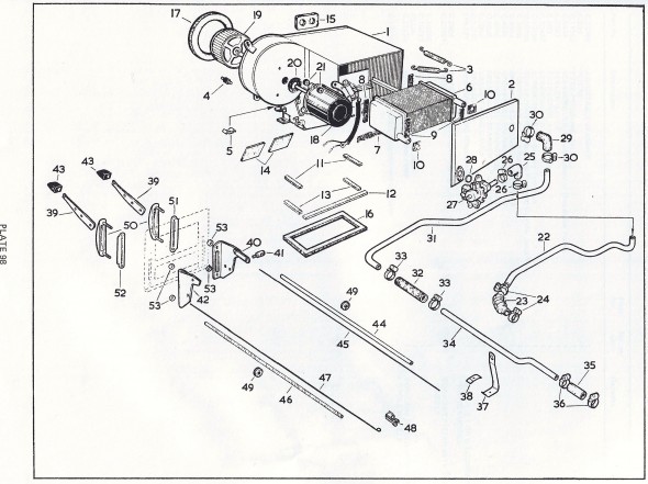
Heater Schematic
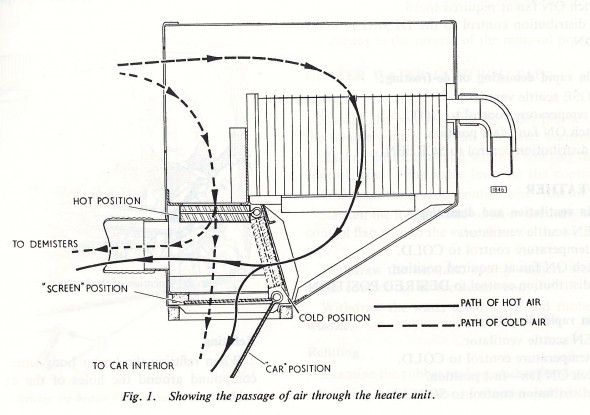
Heater Schematic

Heater Operation

Heater Operation

Heater in Engine Bay
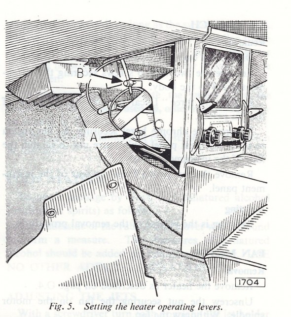
Heater in Engine Bay

Heater Control Levers

Heater Control Levers

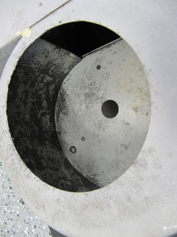
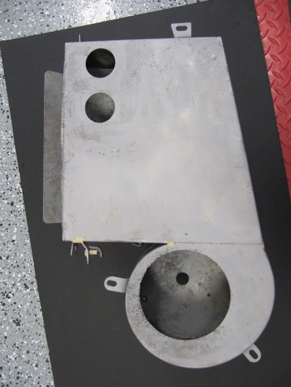
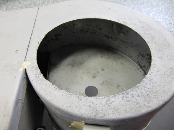
Heater Box

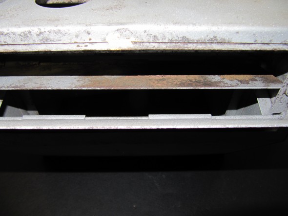
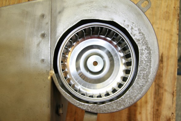
Unfortunately, my heater box assembly seemed to be in a poor state. The drain tube from the plenum must have been clogged which resulted in the system holding moisture combined with the fact that the mice set up home inside the heater casing. The case was pretty rusty, the squirrel cage (fan blower) was completely deteriorated and worst of all the air control flaps were “frozen” in place.
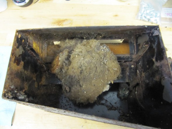
Bonus Mice Nest

Bonus Mice Nest

I decided to try to restore the box and get the frozen flaps working, so I disassembled the heater and media blast the box to so that I could see just how bad it was.

These are some images of the heater before I began disassembly:
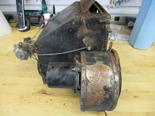
Heater Box 1
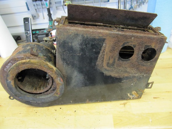
Heater Box 1
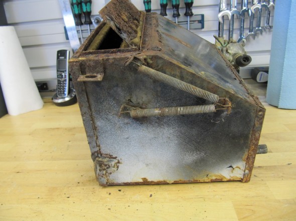
Heater Box

Heater Box

Heater Box 1
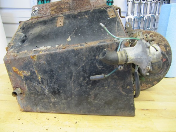
Heater Box 1

Heater Box

Heater Box

Heater Box

Heater Box

Heater Box

Heater Box

Heater Box

Heater Box


These images show the foam rubber seals around the flaps:
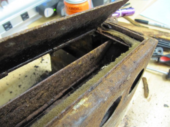
Flap Seal
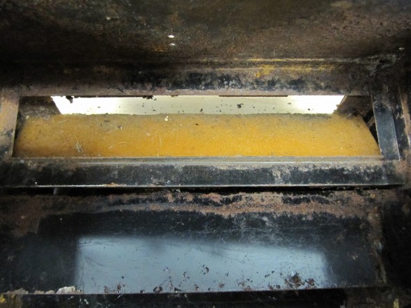
Flap Seal
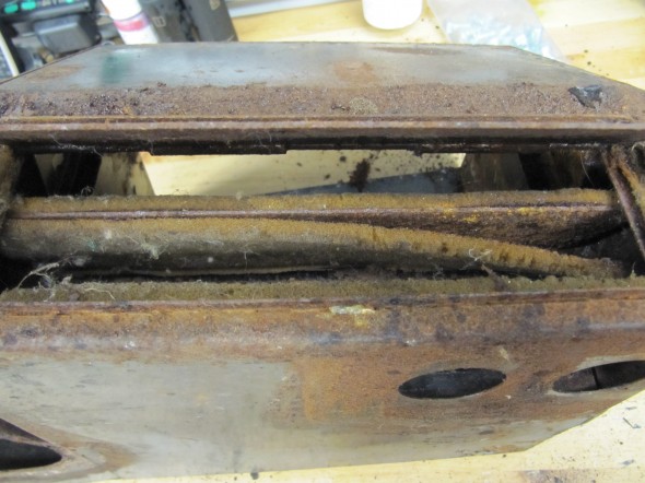
Flap Seal

Flap Seal

Flap Seal

Flap Seal

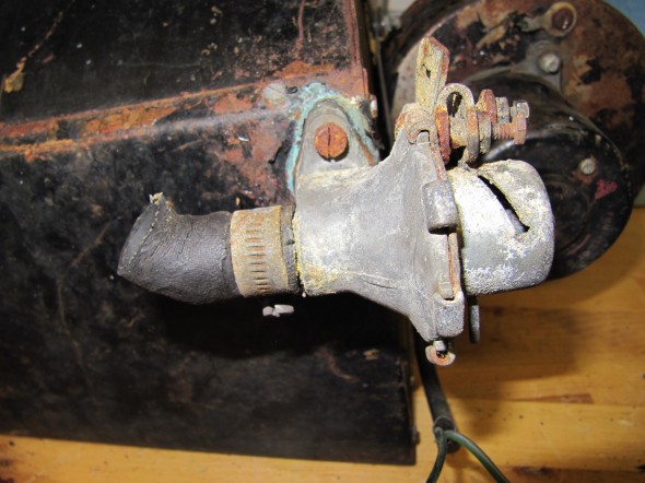
There was a rather thick foam rubber seal between the Heater and the Dash at Volute. This was removed and will be replaced with a new seal. I then removed the Water valve Assembly form the box by removing two cheese head slotted screws #10-32 x 1/2″ with split washers, and the rubber seal that seated the valve to the radiator pipe.
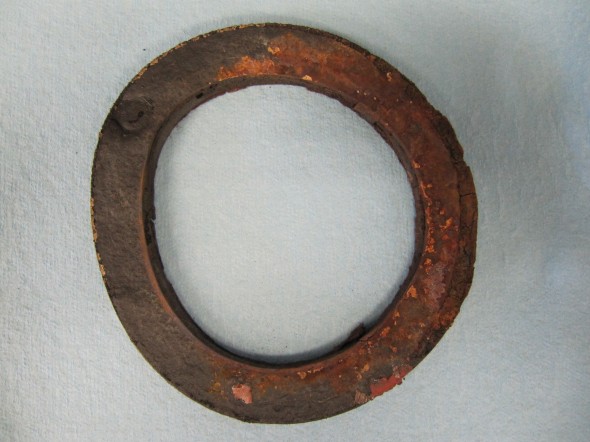
Foam Seal to Body
Foam Seal to Body

Water Valve Assembly
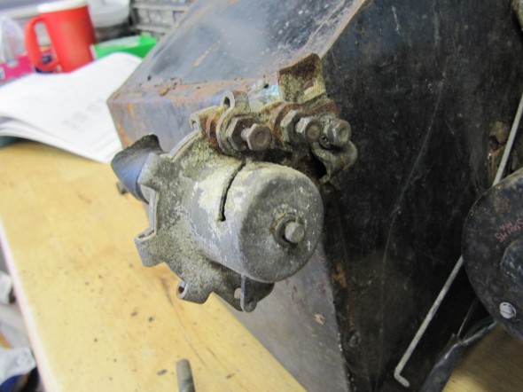
Water Valve Assembly
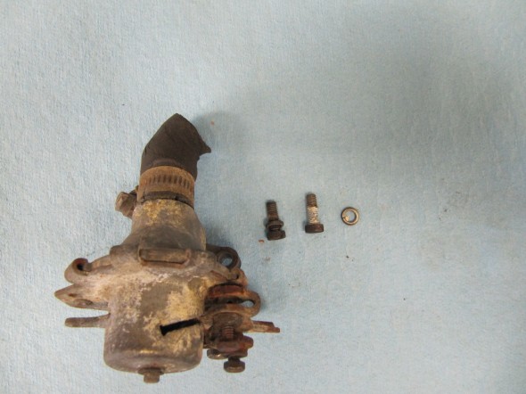
Water Valve Assembly
Water Valve Assembly

Water Valve Assembly

Water Valve Assembly

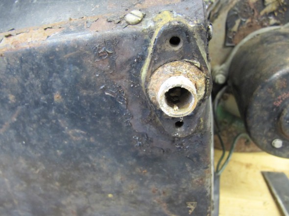
Water Valve Mount
Water Valve Mount


Heater Seals to Firewall

Heater Seals to Firewall

There were 11 slotted #5 x 1/4″ self-tapping screws that held the Lid for the Heater Case to the body of the casing. I removed these to then gain access to the radiator.
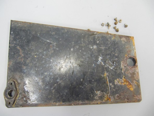
Lid for Heater Case

Lid for Heater Case

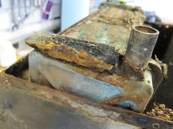
There were two Springs on the outside of the Case identified as Spring, Steadying Air Control Flaps. These were removed and set aside. There were also pieces of felt that provided a cushion between the casing and the radiator. These were removed.
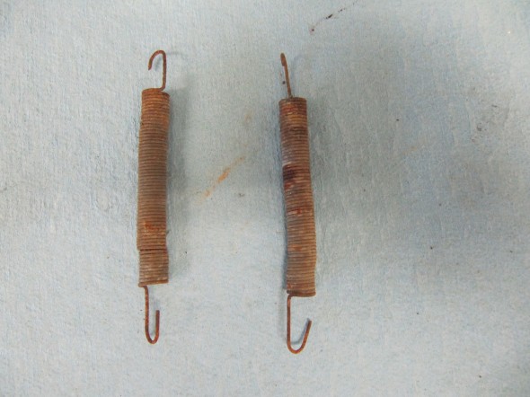
Springs
Springs

Felt Seal

Felt Seal

Felt Seal

Felt Seal

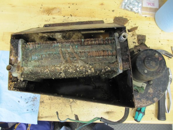
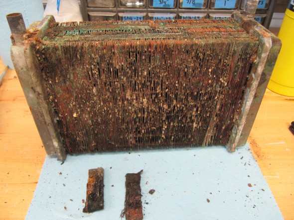
I then lifted out the radiator:
Water Radiator For Heater
Water Radiator For Heater

Water Radiator For Heater

Water Radiator For Heater

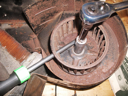
The motor removal was the next step in the disassembly. To get at the three mounting screws for the motor, one must first remove the fan “squirrel cage.” This might normally be done as shown in the image below that was borrowed from another web site. Because more than half of the “fins” in my fan were rusted away, I couldn’t do this. So, I used an air impact wrench which worked like a charm. When the cage or basket is removed, three slotted #10-32 x 1″ machine screws are visible. These can then be held while removing the nuts, rubber and locking washers from the motor side of the case.
Squirrel Cage Removal

Squirrel Cage Removal

This image shows the mounting nuts and the wiring for the motor. After the three nuts were removed the motor could be lifted away from the case.
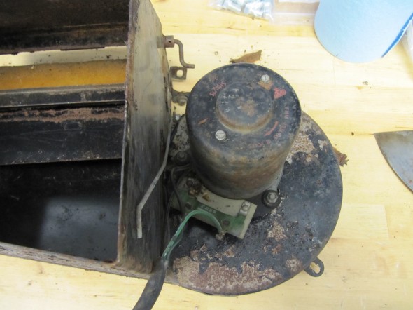
Heater Motor
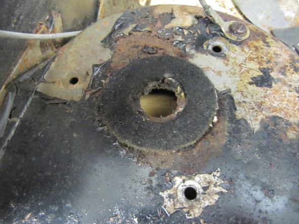
Heater Motor

Felt Washer

Felt Washer

Motor Casing

Motor Casing

Motor Removed

Motor Removed

After stripping out the components it was then time to blast the case with aluminum oxide. This process did reveal several rust pinholes. However, the bad news is that the two movable flaps are both “frozen” in place. I have soaked the hinge rods in Kroil to hopefully release the hinges over time.

These are a collection of images of the box after blasting. The brown in the images on the flaps is not rust. It is adhesive used to secure the foam pads to the flaps:
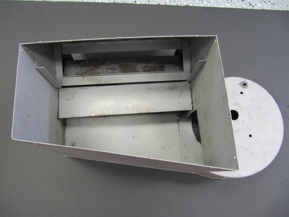
Inside View
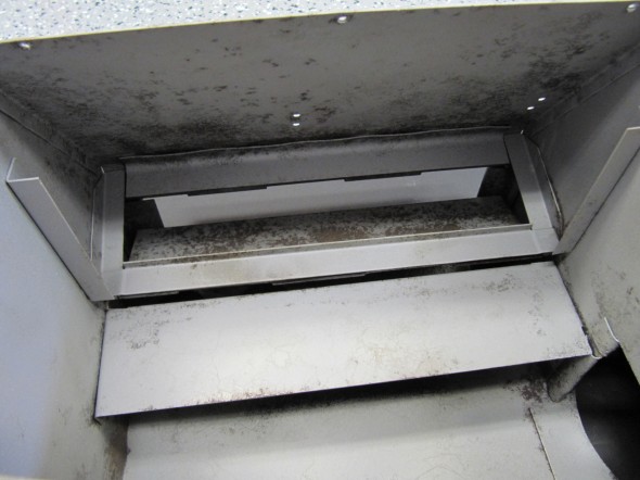
Inside View

Air Flaps

Air Flaps

Assembly Case

Assembly Case

Blower Box

Blower Box

Assembly Case

Assembly Case

Blower Box

Blower Box

Air Flap

Air Flap

Air Flap

Air Flap

Air Flap Rod

Air Flap Rod

Heater Lid

Heater Lid

Heater Lid

Heater Lid

The Kroil did not work so I queried the various email lists and forums. One person suggested heat which I unsuceesfullt tried with a torch. another person suggested a water/molasses solution, but that takes a long time -at least a week. Another suggested electrolysis.

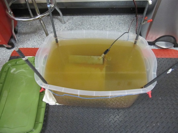
I watched a few YouTube videos on using electrolysis for rust removal, and thought I would give it a try. I emulated this particular video: http://youtu.be/54ADeB6V1rQ

I put the heater box into 14 gallons of water with 14 tablespoons of sodium carbonate. The videos recommend using Arm and Hammer Super Washing Soda, but good luck finding it in a store! I ended up “cooking” baking soda at 200 degrees for an hour to release the carbon dioxide, and thereby turning the sodium bicarbonate into sodium carbonate. Worked like a charm.

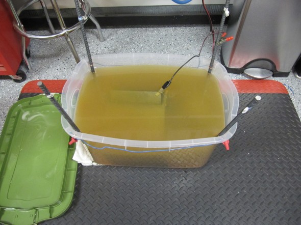
I then attached my battery charger and let the magic begin. I put the box in the solution at 9:15 PM and after two hours I was surprised at how much the water color had changed from clear to rust given how clean the box already was from blasting. The solution just gets into places the aluminum oxide blast abrasive cannot. I then let it all sit until about 8:00 AM this morning.

I cleaned up my mess and put the box on the work table expecting to be disappointed, but I was not. One flap started working immediately, needing little coercion. The second required some pushing and pulling and a little lubrication but it now functions properly as well!

I would use this process again in a minute. Very inexpensive and easy. One more original Jaguar part saved. I have a little pitting to fill with body filler, but otherwise should be a very serviceable unit.

Try it – you will like it.

In the images below the light colored water image was at 9:00 PM almost exactly when the Box went in the solution. The darker colored water image was taken at 8:00 AM the next morning when the Box was removed from the solution.
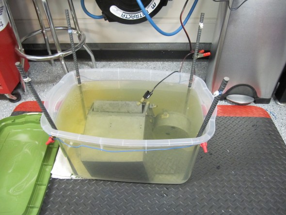
9PM Start Bath
9PM Start Bath

11PM Bath

11PM Bath

8AM Finish Bath

8AM Finish Bath

The Clayton Classics Upgrade

I ordered the upgrade kit for the MK2 heater from Clayton Classics in the UK.

Phil Beveridge.
Manager.
Clayton Classics.
Hunter Terrace,
Fletchworth Gate,
Burnsall Road,
Coventry.
CV5 6SP
Tel: +44 (0)24 7669 1916
Fax: +44(0)2476691969
E-mail:[email protected]

-OR-

Liz Chandler
Sales Adminstrator
Clayton VS Limited
Phone: 02476 691916
email: [email protected]

While awaiting delivery, I had the bottom of the heater box braised to take care of the worst of the pin holes in the bottom of the blower body. The kit arrived with everything necessary to enhance the performance of the original box.

Clayton provided pdf versions of two articles from Jaguar World Monthly that detailed, through photographs and narrative, the removal and dismantling of the original heater box assembly as well as the modifications required. The article was begun and completed over two month’s publication of the magazine. They also included a pdf of their own assembly directions. These are referenced below:

Jaguar Mk2 Heater upgrade installation instructions

classic workshop XK120 Heater Mk2 Heater dec09

Mk2 Heater Upgrade classic workshop jan10

Four modifications to the original box are required.

  1. The air inlet opening in the blower casing must be increased in diameter to 120mm to permit the introduction of the larger fan supplied by Clayton. A perfect cut is not required as the surface will be covered by the seal between the heater and the dash at volute.
  2. A 10mm hole was drilled into the blower casing to permit allen wrench access to the motor shaft to tighten the fan to the shaft. A rubber plug covers the hole after the fan is installed.
  3. Three small holes for self-tapping screws to secure the motor mounting bracket needed to be drilled in the blower casing.
  4. Clayton suggests the original design that incorporated the inner flap was simply a bad design that permitted the dilution of hot air with cold before entering the cabin. Their recommendation is to seal the flap with silicone and to disconnect the flap controls so that the flap remains permanently closed.
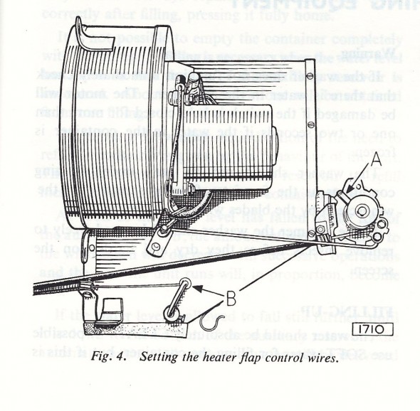
    Heater Flap Control Cables
    Heater Flap Control Cables

    120mm Diameter Heater Box Modification to Allow Larger Fan
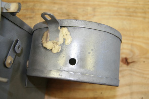
    120mm Diameter Heater Box Modification to Allow Larger Fan

    Access Hole for Fan Shaft Allen Screw
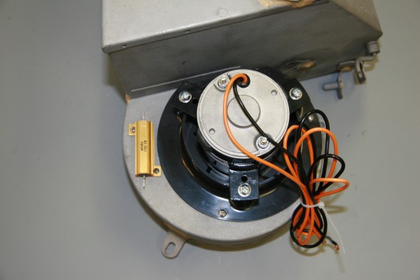
    Access Hole for Fan Shaft Allen Screw

    Clayton Motor Upgrade Installed

    Clayton Motor Upgrade Installed

I completed the first three modifications before powder coating the entire box.

I test fit all of the components and then tested the electrical wiring and connections. The new motor was wired for a positive ground car. To have the fan move in the proper counter clock-wise direction, these wires must be reversed in a negative ground car.

[NOTE]: My wire colors are different than the original wiring scheme.

The orange wire from the motor is connected to ground. The black wire to the “inside” post (closest to the heater box) of the resistor. The slate wire from terminal #6 on the switch is connected to the “outside” post (closest to the blower fan) of the resistor. The white/green wire from terminal #8 on the switch connects to the “inside” post on the resistor. The green/yellow wire from the #4 terminal of the switch is connected to the fuse position #11 for power. With this wiring in place, the lower position of the switch is “off,” the middle position is “Low Speed” and the upper position is “High Speed.”

I created a pigtail (seen blow) from the resistor for the heater fan wiring. Two wires in the pigtail are connected through two-way snap connectors to wires of the same color which route through the firewall and ultimately back to the Fan Switch. The black wire goes directly to the fan motor.
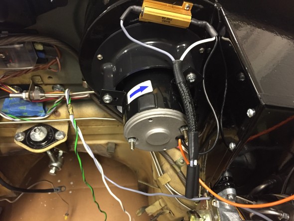
Heater Fan Wiring

Heater Fan Wiring

I contacted Clayton to determine the amperage draw for the upgraded motor and received this response from Phil Beveridge:

Dear Mr.Rose,

At 13.5 volts, running at full speed, the motor will be drawing 10.8amps.

Kind regards,

Phil Beveridge.

Per the Clayton instructions, I used silicone to seal the inner flap in the closed position.
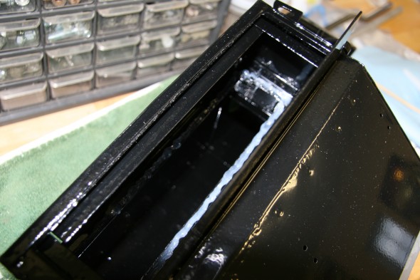
Silicone Sealed Flap Shut

Silicone Sealed Flap Shut

And, added foam to the inside of the bottom flap:
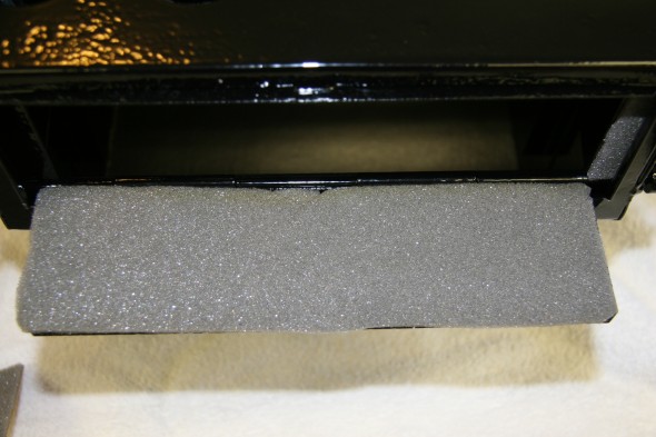
Foam Padding on Flap

Foam Padding on Flap

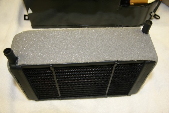
I then installed the motor and the heater matrix after wrapping it with foam:
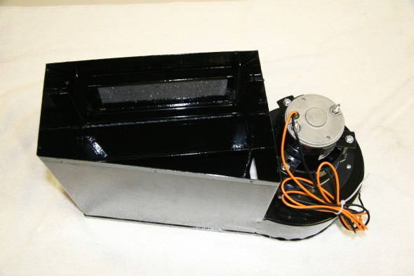
Renewed Heater Box
Renewed Heater Box

Clayton Heater Matrix with Padding

Clayton Heater Matrix with Padding

The next step was to install the heater box front lid:
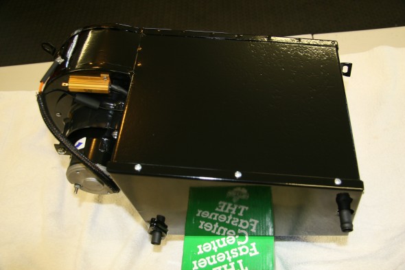
Heater Box Lid Installed

Heater Box Lid Installed

Water Valve

I ordered and installed a new water valve and rubber “O” ring seal.
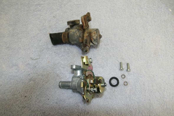
Original and New
Original and New

"O" Ring Seal

“O” Ring Seal

Valve Installed

Valve Installed

Heater Pipe Mounting Clips

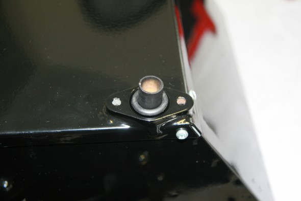
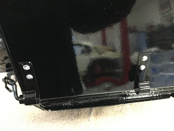
Two spring clips are pop riveted (1/8″) to the angled face of the heater box. These are used to secure one of the water circulation pipes to the box. The Clips were originally painted black so they were media blasted and then painted with POR 15.
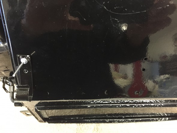
Holes in Heater Box for Pipe Clips
Holes in Heater Box for Pipe Clips

Heater Pipe Clips Riveted to Heater Box

Heater Pipe Clips Riveted to Heater Box

Trial Fitting of the Heater Box

I need to install the heater box for completion of the wiring harness and to see how the box would fit with other “non-original” items in the engine bay. I was particularly curious about any conflicts that might arise from the addition of the power steering pump.

There are several foam insulation seals that need to be installed between the scuttle, firewall and base of the heater. These were sourced from Clayton, XK’s Unlimited and McMaster Carr and installed temporarily.
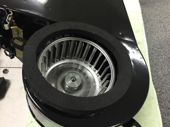
Heater Blower Firewall Seal Installed
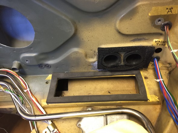
Heater Blower Firewall Seal Installed

Closed Cell Seals at Heater Flap & Hose Openings

Closed Cell Seals at Heater Flap & Hose Openings

Three rubber “bobbins” serve as cushions and mounting posts for the heater box to the firewall.
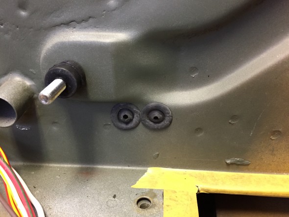
Heater Mounting Stud and Heater Cable Firewall Grommets

Heater Mounting Stud and Heater Cable Firewall Grommets

These are actually two 1/4″-28 hex head cap screws molded into each of the three rubber cushions. I used a 1/4″ – 28 x 1″ machine hex head screw on the lower right mount at the heater’s base and a 1/4′ – 28 x 1 1/4″ machine hex head screw on the lower left mount. Before placing the heater box in position I also installed the two firewall grommets for the heater control cables. These are visible in the image above. In the final assembly only one of these will be used due to the permanent closure of one of the circulation flaps as recommended by Clayton in their upgrade kit. Both heater hose rubber elbows were installed in the bulkhead.
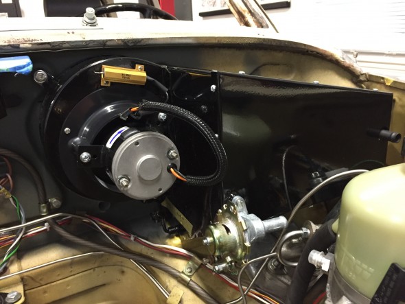
Heater Box Installed

Heater Box Installed

Air Distributor Box  

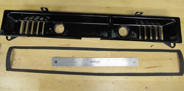
My next task was to clean up the air distributor box that is mounted in the center and below the dash with two 1/4″ – 28 x 1″ hex head bolts and two 1/4″ – 28 x 1/2″ hex head bolts with flat and shakeproof washers. As the images show, a felt gasket is glued to the edges of the box. A small piece of black electrician’s tape was found placed over two holes in the box. The box was blasted with aluminum oxide and powder coated gloss black.
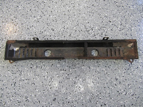
Air Distributor Box
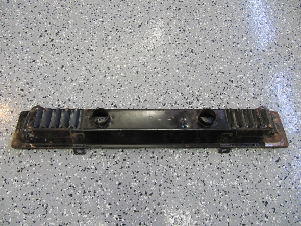
Air Distributor Box
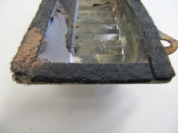
Air Distributor Box

Air Distributor Box

Felt Gasket
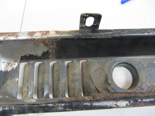
Felt Gasket

Tape Blocking Holes

Tape Blocking Holes

Tape Blocking Holes

Tape Blocking Holes

I media blasted the box to prepare it for powder coating:
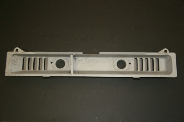
Clean Air Box
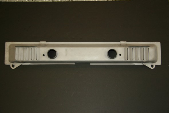
Clean Air Box
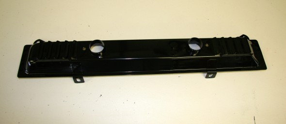
Clean Air Box

Clean Air Box

Powder Coated Air Distributor Box

Powder Coated Air Distributor Box

To prepare for the trial installation of the Air distributor Box, I cleaned the mounting surfaces and applied some self-etching primer. This will, of course be removed when the car is blasted.
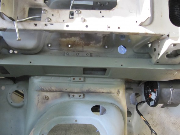
Mounting Location for the Air Distributor Box

Mounting Location for the Air Distributor Box

The Air Distributor Box had a felt gasket around its perimeter when I removed it from the car. I made and glued a closed cell foam gasket to the Box before mounting.
Foam gasket for the air distributor box
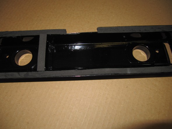
Foam gasket for the air distributor box

Air Distributor Box Foam Gasket
Air Distributor Box Foam Gasket

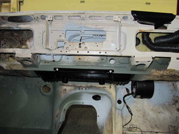
Air Distributor Box Installed
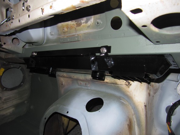
Air Distributor Box Installed

Air Distributor Box Installed

Air Distributor Box Installed

At the suggestion of Eric Kriss, I also concluded that given the somewhat poor performance of the MK2 heating system, it made little sense to send heat to the rear of  the car. What heat was produced would be best restricted to the front seats! He closed the two vent outlets in the air distributor box with expandable rubber plugs, and I followed his lead. I picked up two 1-3/8″ plugs from my local ACE Hardware and they work perfectly.
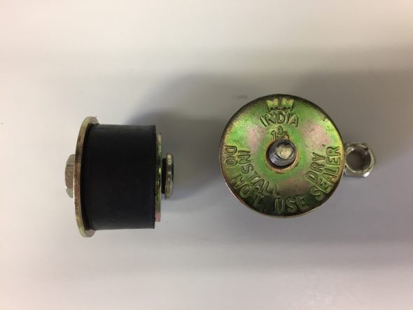
Expandable Plugs for Air Distributor Box
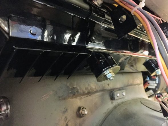
Expandable Plugs Installed in Air Distributor Box

Front Heater Return Pipe

Hot Water Circulation

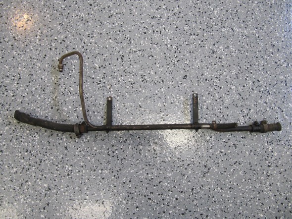
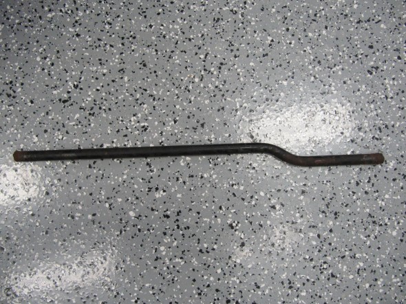
The hot water circulates through the heater via steel pipes and rubber hoses. Though not as original, I used stainless steel pipes available as a kit form SNG Barratt or XKs Unlimited. They should be painted black but I am going to just leave them unpainted since they would probably just get scratched anyway.The Rear Return Pipe, on Scuttle, At Rear of Cylinder Block connects to the Front Return Pipe and then to an adaptor at the Water Pump. The pipe is secured by a clip bracket on the firewall and by two clips on the heater box:
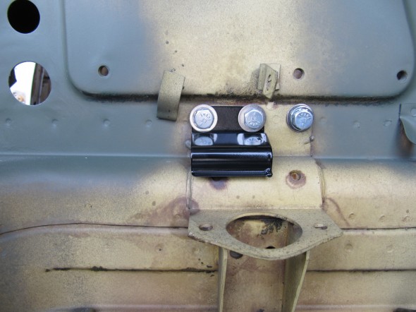
Heater Pipe Clip
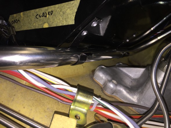
Heater Pipe Clip

Heater Pipe Clipped to Heater Box

Heater Pipe Clipped to Heater Box

The feed pipe via a rubber elbow connects to the heater radiator inlet pipe, and to the water outlet on the intake manifold. The image below shows two of the pipes installed in the engine bay and connected to the heater:
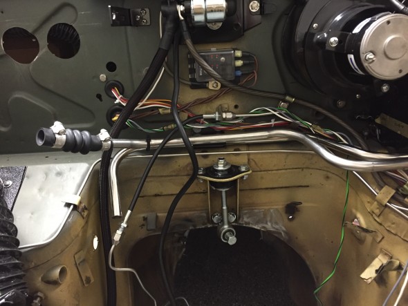
Rear Heater Pipes Installed

Rear Heater Pipes Installed

The Front Return Pipe is secured parallel to the RH side of the engine block with brackets mounted to inlet manifold studs ( the third stud from the front of the engine and the third stud from the rear). The Brake Servo Vacuum Pipe is paired with the Front Return Pipe held by the same brackets.

Two identical elbow hoses part C16655 are used to connect the pipes to the heater matrix and water valve assembly.  An accordion type hose, part C21961, connects the feed pipe to the adapter at the rear of the inlet manifold. This hose can be seen in the image above.

The front return pipe and the rear return pipe are connected with a straight piece of hose, part C14999/3. A shorter straight piece of hose connects the front the front return pipe to the adaptor on the water pump. All of the hoses are secure to the hard pipes with Cheney clamps that were sourced from XKs Unlimited.

The offset in the Front Return Pipe is to the front of the car.  I removed the two Brackets On Studs of Inlet Manifold by loosening the two 3/8″ – 24 stud nuts. At the front of the pipe I disconnected the hose 9/16″ hose clamp and pulled the pipe away with the 3 1/2″ Hose, From Front Return Pipe to Adaptor on Water Pump. The hose uses two 9/16″ clamps to connect the hose to the pipe and to the adaptor. The Hose From Rear Return Pipe to Front Return Pipe is 8 1/2″ long also secured with two 9/16″ clamps. For ease of removal, I disconnected the Vacuum Pipe Assembly from the top of the Inlet Manifold, and could then lift away both pipes and brackets from the engine block.

The Front Return Pipe and the Vacuum Pipe were then separated by loosening each of the mounting brackets components held together with a hex head #10 – 32 x 1″ machine screws, nuts and shakeproof washers. Two  1″ long pieces of rubber hose (slit length wise) wrapped around the vacuum hose to keep the two pipes from rattling against each other.
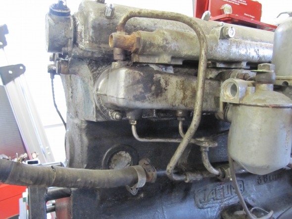
Front Return Pipe at Side Of Cylinder Block - Rear Hose

Front Return Pipe at Side Of Cylinder Block – Rear Hose
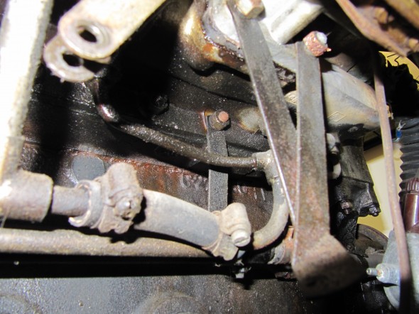
Front Pipe Hose
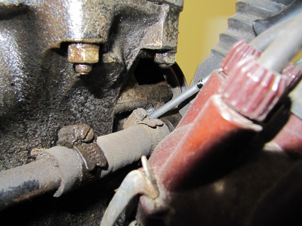
Front Pipe Hose
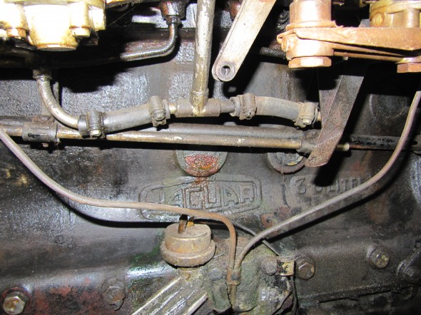
Front Pipe Hose

Front Pipe Hose

Front Return Pipe
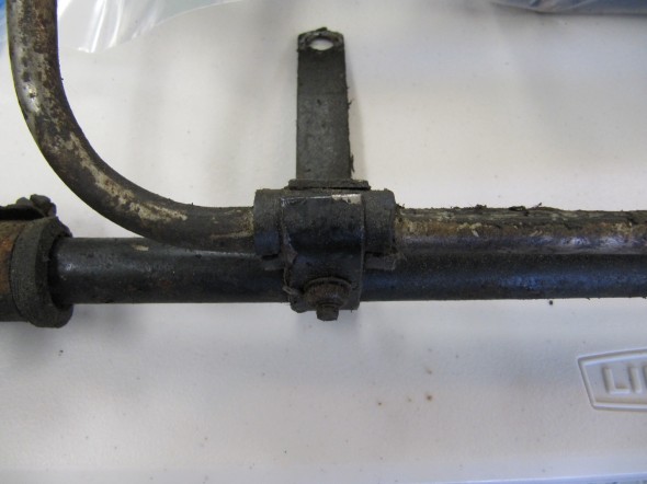
Front Return Pipe

Pipe Brackets

Pipe Brackets

Front Return Pipe

Front Return Pipe

Front Heater Return
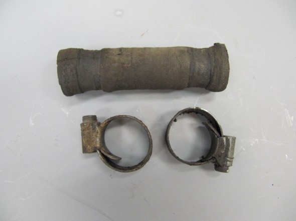
Front Heater Return

Hose from Front

Hose from Front

Hose from Rear

Hose from Rear

Hose from front return pipe to adaptor on Water Pump 1

Front Return Pipe Hoses

Brackets prepared for painting:
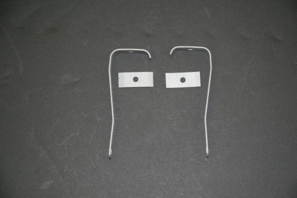
Brackets-on-Studs-of-Inlet-Manifold-for-Fixing-of-Heater-and-Servo-Pipes Ready to Paint
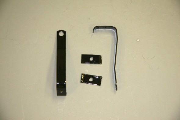
Brackets-on-Studs-of-Inlet-Manifold-for-Fixing-of-Heater-and-Servo-Pipes Ready to Paint

Cover Plate Over Pedal Mounting Cut-out on Centre Dash

Cover Plate Over Pedal Mounting Cut-out on Centre Dash

I am replacing the Front Heater water return pipe with a new stainless pipe:Stainless heater Front Return Pipe
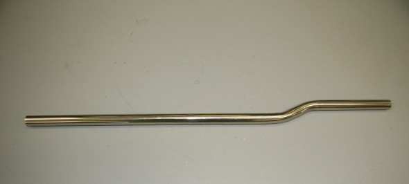
I also purchased a new foam rubber seal from the the heater to the dash volute.
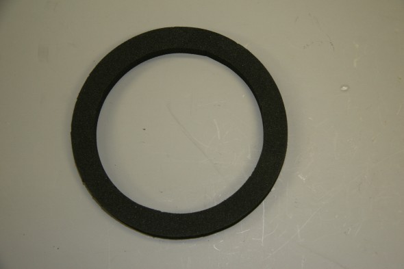
Rubber Seal from heater to Dash Volute

Rubber Seal from heater to Dash Volute

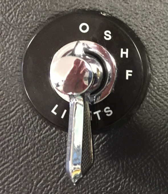
Heater Control Lever Assemblies

Two levers mounted in the central control panel in the console control the temperature and distribution of air into the cockpit. The temperature control – marked “Hot” and “Cold”situated below the instrument panel operates a valve which controls the flow of air through the heater. When the control is placed in the “Cold” position the supply of air from the heating element is completely cut off so that cold air can be admitted for ventilating the car in hot weather. Placed in the “Hot” position the maximum amount of air passes through the heating element. By placing the control in intermediate positions varying degrees of heat can be obtained.

The distribution control –  marked “Car-Screen” controls the proportion of air directed to the windscreen or the interior of the car. Placed in the fully upward position the maximum amount of air will be admitted into the car interior. Placed in the fully downward position the maximum amount of air is directed to the windscreen for rapid demisting or defrosting. By placing the contra in intermediate positions varying proportions of air can be directed into the car interior and to the windscreen.

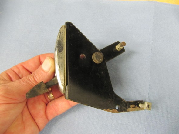
The lever controls consist of the mounting brackets and control arms with chrome bezels and inscribed instructional plates. A plastic knob is screwed into each control arm. Cable attachment hardware and two distance pieces for each chrome bezel mounting post is located on each control arm and bracket. Both assemblies wherein reasonably good condition. I will try to replace the inscribed plates if I can locate a source. I cleaned both assemblies, polished the chrome, lever knob and instructional plates and primed and painted each.

Temperature Control Lever
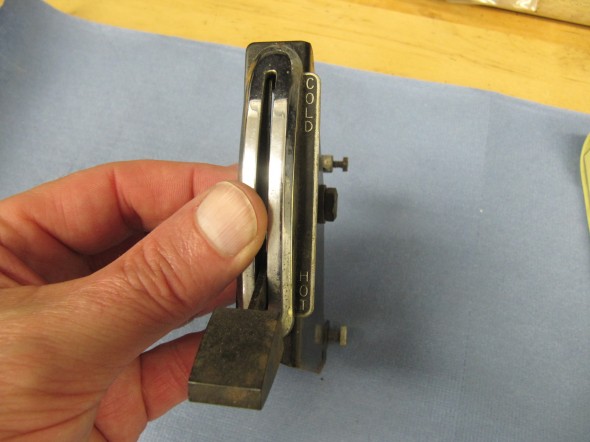
Temp Control Lever
Temp Control Lever
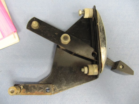
Temp Control Lever
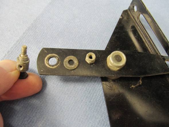
Temp Control Lever

Temp Control Lever

Temp Control Lever

Temp Control Lever

Temp Control Lever

Distribution Control Lever
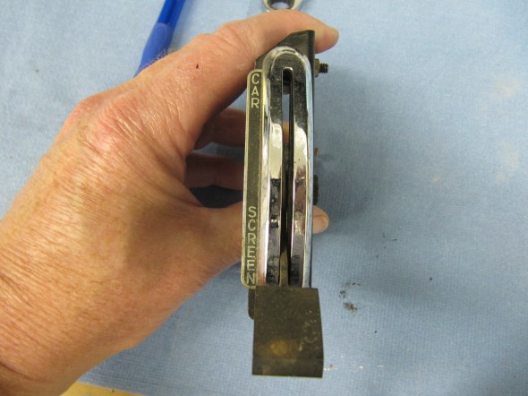
Distribution Control Lever
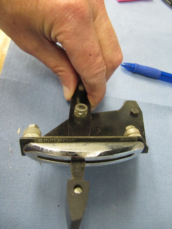
Distribution Control Lever

Distribution Lever
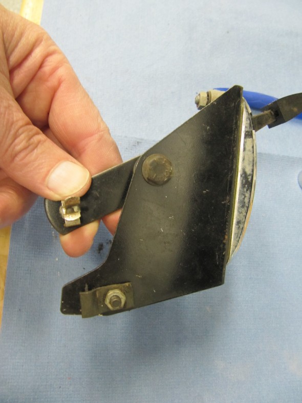
Distribution Lever
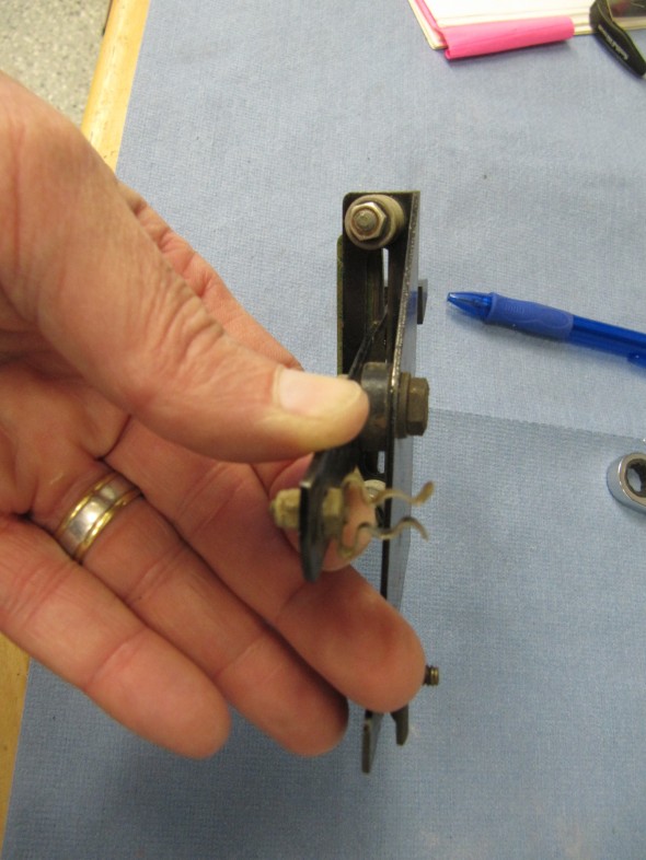
Distribution Lever

Distribution Lever

Distribution Lever

Distribution Lever

Temperature and Air Distribution Levers after Renewal
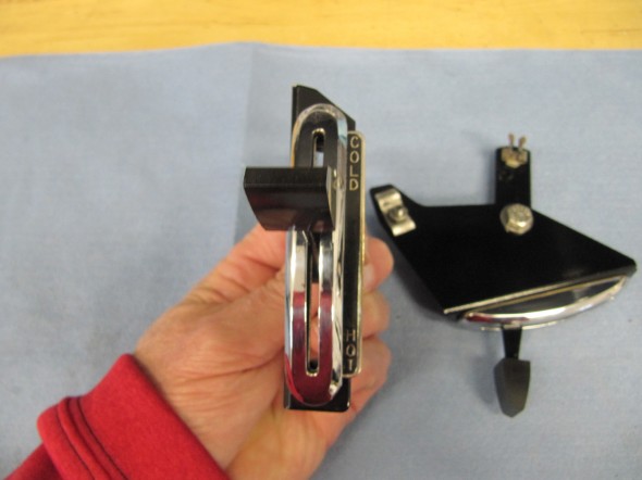
Temperature and Air Distribution Levers
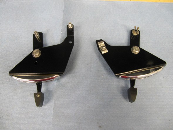
Temperature and Air Distribution Levers

Temperature and Air Distribution Levers

Temperature and Air Distribution Levers

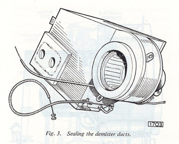
Windscreen Demister Nozzles

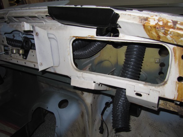
Each of the demister nozzles is attached to the scuttle with two #6 x 1/2″ pan head screws. Flexible hose connects each nozzle to rubber elbows in the firewall that access the heater aperture in the scuttle. Each nozzle was primed and painted gloss black.
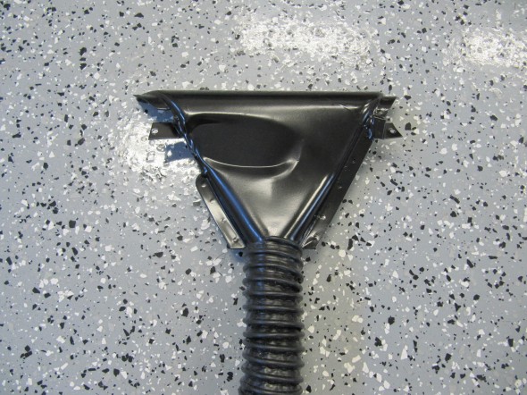
RH Demister Nozzle with Hose
RH Demister Nozzle with Hose

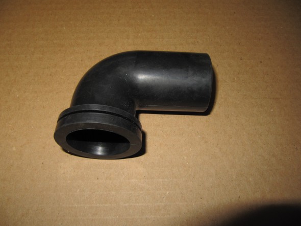
Rubber Elbow

Rubber Elbow

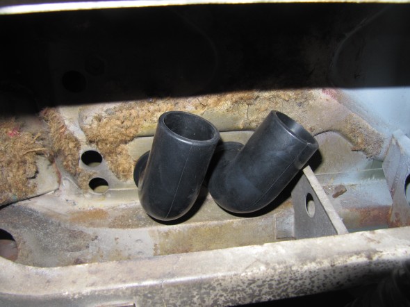
The hose fits inside the rubber elbow. It is a very tight fit. I boiled the elbows in water to make them more pliable and then forced the hose inside. To open the passage and remove any hose restriction I pushed a broomstick up the hose to the elbow.
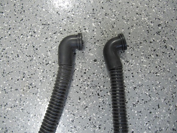
Hoses Installed in Elbows

Hoses Installed in Elbows

While the RH Demister Nozzle fit into the bodywork quite easily the LH side was very tight so I opened up the sheet metal with a dremel to improve access.
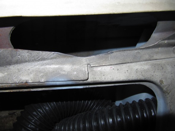
Tight Fit Modification
Tight Fit Modification

Rubber Elbows in Firewall
Rubber Elbows in Firewall

RH Demister Installed
RH Demister Installed
MK2 Cruise Control

Rostra Cruise Controlcruise-control-installation-disclaimer-001 

Components

I installed an Audiovox CCS-100 Cruise Control system on my Healey and found it to be a useful modification. I am over six feet tall and the seating position in British cars can be uncomfortable on long drives. The cruise control makes those trips a bit more relaxing and enjoyable. 

Rostra Precision Controls, Inc. manufacturers the cruise control system I am using in the Jaguar MK2. Many of the same components of Rostra’s system have evolved from the earlier version marketed by Audiovox. The earlier iteration worked on a vacuum servo while the current version by Rostra uses all electronic components. Rostra also manufactures a number of other automotive electronic devices such as Bluetooth systems, rear cameras and etc. The company is located in North Carolina and this is their website: http://www.rostra.com. Rostra does not sell directly, but they have many other vendors selling their products such as Summit Racing and many others.

There are a number of components in the cruise control system. These include:

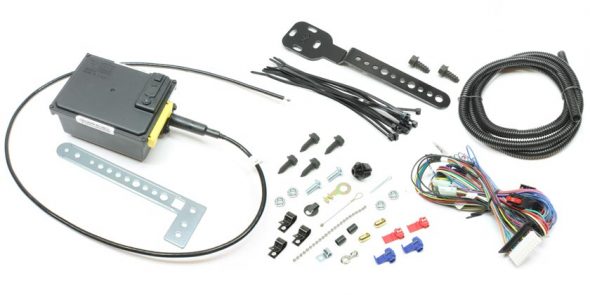
Part #250-1223: The Global Cruise Module Assembly includes the universal Global Cruise servo motor, throttle cable, universal mounting brackets, wiring harness and hardware package for making electrical and throttle control connections. The servo motor mounts in the vehicle’s engine bay.

Rostra 250-1223 Servo

Rostra 250-1223 Servo

These are the directions provided with the Global Cruise Module:rostra-global-cruise-250-1223-instruction-manual

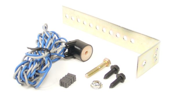
Part #250-4165: includes the speed signal generator with sensor, magnet and strap.

Universal Magnet Speed Signal Generator

Universal Magnet Speed Signal Generator

Cars more modern than the 64 Jaguar equipped with electronic speed signal (VSS) capability don’t require a magnetic sensor, but in the analog world of the MK2, a magnet is secured to the propshaft and the sensor is located in close proximity to measure revolutions or pulses per mile. These are the directions provided with the Universal Magnet Speed Signal Generator kit: rostra-installation-of-the-road-speed-sensormagnets-pick-up-coil

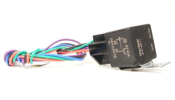
Part #250-4382: is a pre-wired five pin relay to compensate for the use of LED brake lighting. 

Relay Package

Relay Package

While the included primary wiring harness of the Global Cruise system includes wire leads meant to be attached to both the ‘hot’ and ‘cold’ sides of the brake pedal sensor to disengage the cruise control when the brake pedal is depressed, the proper ground signal is no longer present when a vehicle has been outfitted with LED lighting accessories such as LED brake lights. In a case like this, a 5-prong automotive relay must be used to provide the ground signal to cancel the cruise control once engaged. A MK2 owner using original incandescent light bulbs wouldn’t need this relay, but I have converted my lights to LEDs so this addition is required. These are the directions provided with the pre-wired 5 pin relay: rostra-250-4382-5-wire-relay-wiring-diagram

Part #250-3592: is the dash mounted control switch that includes a small LED light that illuminates when the cruise is engaged. An otherwise identical control switch, but without the engagement light is also available and is part #250-3593. I am using #3592 that also requires an additional 5 pin relay. I am not mounting the switch on the dash, as I am “hiding” my switch in the modified center console where the ash tray was originally located.

Universal Dash Mount Switch

Universal Dash Mount Switch

These are the directions provided with the control switch: rostra-dashmount-installation-instruction

Installation

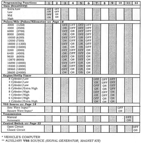
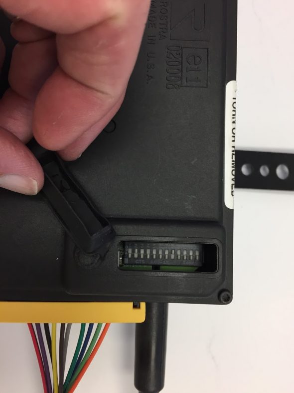
Step one for me was to set the electronic switches in the global cruise module. There are a total of twelve switches with “On/Off” settings. Rostra encourages beginning the installation with the factory settings and then modifying the settings based on individual applications.

rostra global cruise control module settings

rostra global cruise control module settings

Global Cruise Switches

Global Cruise Switches

The twelve switches configure the control module for the type of car in which the system is being installed.

Switches #1 and #2 are for sensitivity or gain. Rostra’s directions state the following: Gain is how the cruise reacts to road conditions and motor size. Always start at Mid gain. If vehicle surges, change gain. For a fast surge, switch to a low or extra low gain setting if needed to tune the cruise. If there is a slow surge, switch to high gain. Therefore, I will initially set switch #1 to “OFF” and switch #2 to “ON.”

Switches#3 through #6 are for the pulses for minute. I assume (always dangerous) that the MK2 will probably have about 3,000 to 3,500 rpms at 60 mph therefore, I will initially set switch #3 to “ON,” switch #4 to “OFF,” switch #5 to “OFF,” and switch #6 to “OFF.”

Switches #7 through #9 are for the engine set-up (cylinders). Rostra’s directions state the following: Engine/Setup timer is how fast the cruise retracts the cable at onset. Always start at low. If vehicle drops below set speed but then recovers, switch to a high or extra high if set speed is not acceptable. Of course the Jaguar MK2 3.8 is a 6 cylinder engine therefore, I will initially set switch #7 to “OFF,” switch #8 to “ON,” and switch #9 to “OFF.”

Switch #10 is for the input source – Sine Wave or Square Wave. The Jaguar MK2 must use the magnet kit as the pulse indicator and as the chart above indicates, switch #10 is set to the Sine Wave Input or “OFF.”

Switch #11 is for the transmission type – manual or automatic. I have a manual gearbox in my MK2 therefore, I will set switch #11 to “OFF.”

Switch #12 is for the type of control switch. Rostra’s directions state the following: Your control switch is an Open Circuit Control Switch if: Its Rostra part number is 250-3592 (among others). I am using the dash panel control switch #250-3592, therefore in keeping with the table above switch #12 is set to “OFF.”

In summary:

#1  OFF

#2  ON

#3  ON

#4  OFF

#5  OFF

#6  OFF

#7  OFF

#8  ON

#9  OFF

#10 OFF

#11 OFF

#12 OFF 

Global Cruise Module Mounting

The Rostra instructions indicate that the Module should NOT be mounted in the following areas

* Under the fender.
* Under the vehicle.
* Directly to the engine.
* With the cable pointed down.
* Near sharp, hot or moving objects.
* Near ignition coil [No closer than 10″]
* In the passenger compartment (Noise).

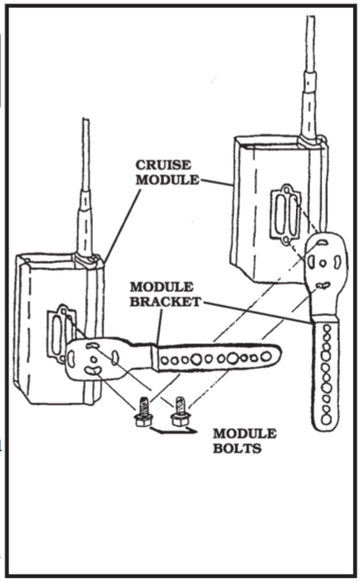
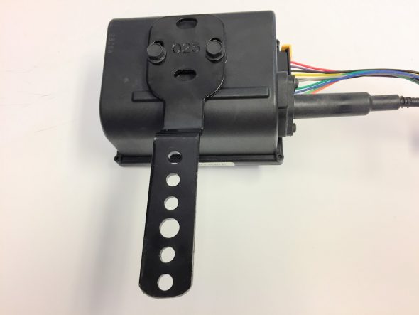
The module needs to be mounted in a location that will provide sufficient “reach” for the module’s throttle control cable to link to the carburetor throttle linkage. A fairly heavy duty bracket is provided to mount the module to the car and it can be mounted in one of two orientations:

Cruise Control Module and Mounting Bracket

Cruise Control Module and Mounting Bracket

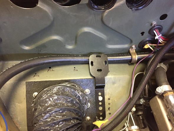
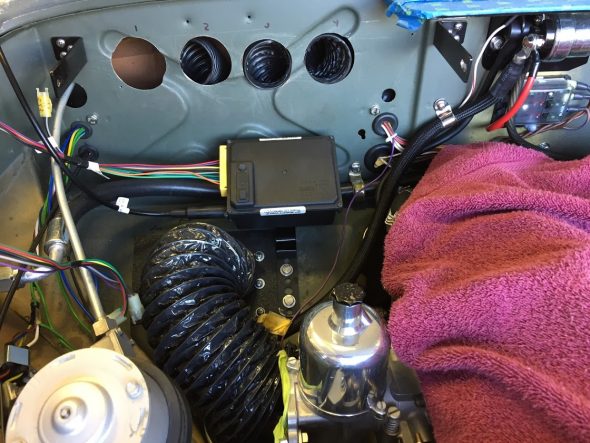
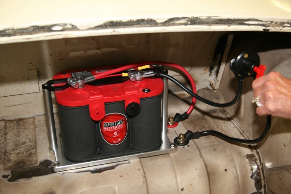
My battery is relocated to the boot to accommodate the placement of the air conditioner evaporator on the RH firewall. I had enough clearance to mount the module under the evaporator. This location permitted me to hide the module as best I could.

Global Cruise Module with Mounting Bracket

Global Cruise Module with Mounting Bracket

Mounting Bracket

Mounting Bracket

Global Cruise Module Installed

Global Cruise Module Installed

Global Cruise Module Wiring

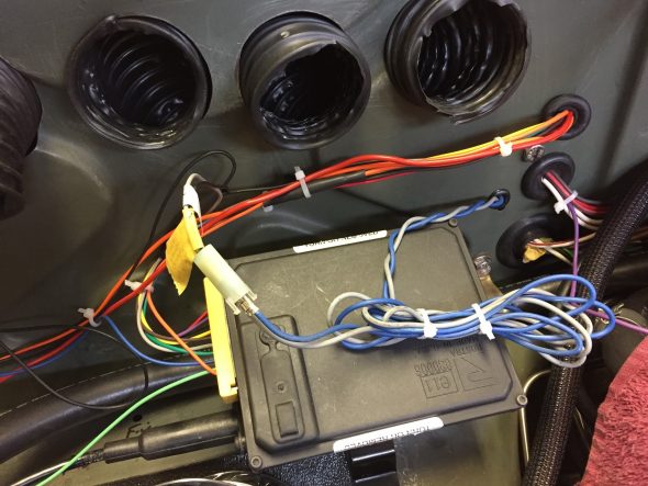
Because the Rostra kit is for universal applications, the wire runs in some cases are quite long and I decided to shorten a number of them which then effected some of the connectors that were used. There are also situations in which not all of the wiring provided is used.

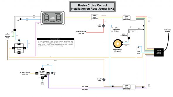
My wiring diagram, tailored for my 1964 Jaguar MK2 application, is provided below. As the disclaimer at the top of this post indicates, the wiring description in this post journals what I did for my car. It is not my intention to describe what you should do for your car!rostra-cruise-control-wiring-for-jag-mk2-001

This is a link to the same wiring diagram as a pdf file rather than as a jpeg file.rostra-cruise-control-wiring-for-jag-mk2

The Rostra instructions for the Global Cruise Control Module indicate that the wiring emanating from the module needs to pass through a 3/4″ hole in the firewall. I already have an unused firewall port as seen in the image above, so I will use it for the wiring. I slid a firewall rubber grommet over the wiring harness to help seal the opening. The control module has a total of ten (10) wires, although the black and grey wires are spliced to create three black wires and two grey wires for a total of twelve (13) wires. The wires are “bundled” for routing through the firewall.

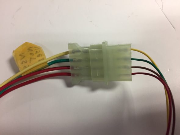
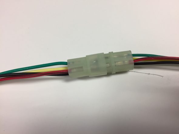
Bundle One: red/brown, yellow, black and green wires from the control module to a clear plastic female four pin connector. This connector is mated with a male four pin connector with four wires of the same colors. The red/brown, yellow and green wires are then routed to a male clear plastic flat four pin connector.

Flat Four Pin Connector from Global Control Module to Panel Switch

Flat Four Pin Connector from Global Control Module to Panel Switch

The black wire is routed to a male clear plastic two pin connector joining with a blue wire. These wires are not used in the system for the Jaguar. The black and blue wires are factory labeled as “to control switch six pin only.”

Red/Brown Wire – This wire is routed to a male clear plastic flat four pin connectorThis wire is routed to the “hot” side (constant 12+ volts) of the brake switch.

Bundle One Cruise Control Wires

Bundle One Cruise Control Wires

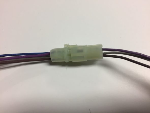
Bundle Two: violet, grey, and brown wires from the control module to a clear plastic female four pin connector.

Bundle Two Cruise Control Wires

Bundle Two Cruise Control Wires

Violet Wire – This wire is routed to the “cold” side of the brake switch (0 resistance when brake is not pressed, and 12+ volts or open resistance when the brake is pressed.

Black Wire – This wire is spliced to create two (2) black wires. One of the black wires is joined with a grey wire in a clear female plastic connector with a label entitled “optional signal generator.” The other black wire has a ring terminal connector on it and is attached to a ground connection on the chassis.

Yellow Wire – This wire joins with the 

Road Speed Sensor/Magnets and Pick-up Coil Installation

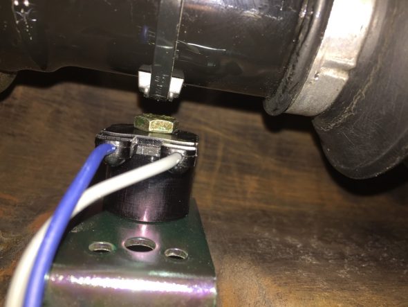
The Rostra instructions indicate that for rear wheel drive vehicles measuring distance traveled in miles per hour, one magnet should be used. Once I had the rear suspension in the car with the propshaft in the “normal” position I was able to install the speed sensor. 

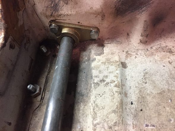
First, I bolted the road speed pick up coil to the thinner bracket supplied in the kit using the 1/4″-20 x 1 1/2″ bolt and the stamped nut being careful to not over tighten the nut as too much torque will damage the coil.

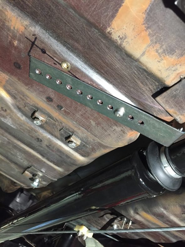
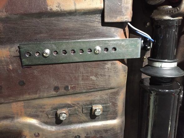
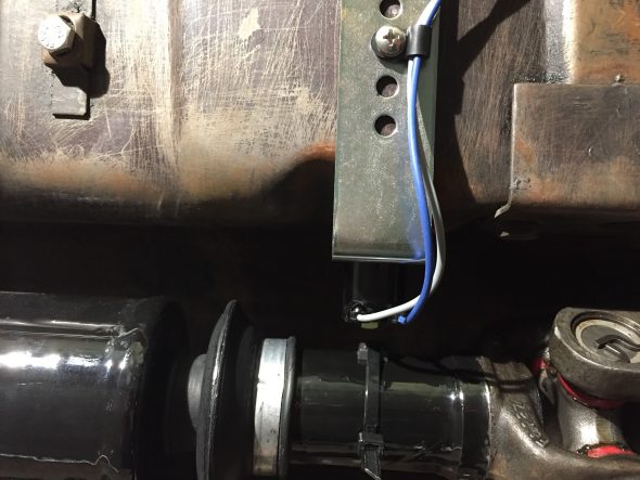
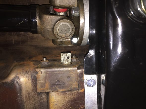
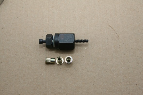
Second, I positioned the bracket under the car so that the coil bolt head was 3/4″ plus or minus 1/4″ from the propshaft and no more that 12″ in back of the U-joint. The pick-up coil was positioned in the middle of the propshaft and mounting holes were marked on the floor underside. I then installed two nutserts in the floor and mounted the bracket with two #10 -24 x 1/2″ machine screws.

Positioning the pick-up coil and bracket

Pick-up coil and bracket mounted

Third, secured the magnet with the long plastic tie strap provided. The ribbed side of the strap is against the magnet and seated between the two ribs on the magnet casing. I then tightened the strap using a screwdriver against the clasp and pulled the strap with pliers. This requires some effort to get the strap tight enough to avoid slippage. As the instructions indicated, I then cut the excess strap flush to 1/16″ from the lock.

Pick-up Coil and Magnet on propshaft

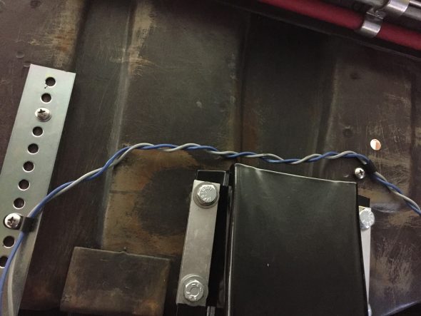
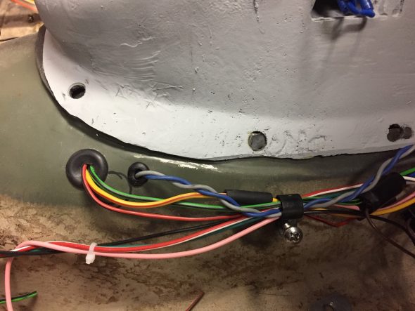
Fourth, I then ran the blue and grey wires from the pick-up coil under the car and up through a rubber grommet in the gearbox tunnel. The wiring then travels under the center console and up and under the dash exiting the firewall and connecting to the clear two wire plastic connector. I temporarily left the blue and grey wires without a connector, but will add the black male connector and cover the wiring in a rubber tube upon final installation. The Grey wire connects to the grey wire near the control module and the blue wire connects to the blue wire. Both will be shortened at final installation as well.

Wiring from Pick-up Coil

Pick-up coil wiring to gearbox tunnel

Pick-up coil wiring exiting Gearbox Tunnel

Pick-up Coil Wiring to Global Cruise Control Module

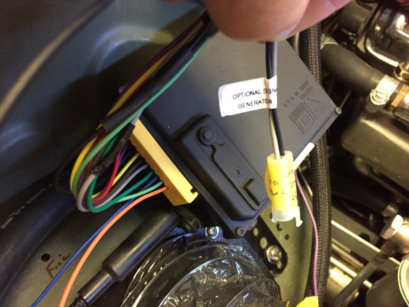
The female connector with the grey and black wires is identified from the factory with a white label entitled “optional signal generator.”

Optional Signal Generator Connector

Optional Signal Generator Connector


Attaching the Cruise Cable from the Cruise Module to the Throttle

It is important for safety and proper operation to follow the instructions provided with the kit!

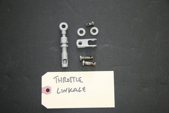
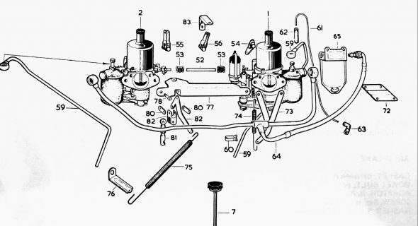
Because of its universal mounting applications, the Rostra kit includes numerous brackets and connectors. You end up using very few of the components that they provide. For the Jaguar 3.8 MK2, one needs to align the cable mounting and the Throttle Link Rod Assembly/Intermediate Throttle Lever.

Throttle Link Rod Assembly

Carb and Fuel Connections Schematic

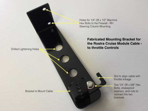
I have “over-engineered” the bracket I fabricated for the cruise module cable, but I like to use existing holes/captive nuts and etc. whenever possible to avoid changes to the car’s body. In this case for the base of my bracket, I used two of the captive nuts available at the cover plate for the steering column on the RH side of the firewall since these are unused given that my car is LH drive. 

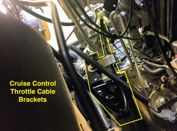
The second image below shows the bracket and cable installed although it is somewhat difficult to ascertain the components.

Rostra Crusie Module Cable Bracket

Rostra Cruise Module Cable Brackets Mounted

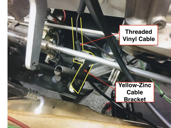
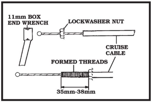
As can be seen in the image above a yellow-zinc bracket attaches to the black bracket I fabricated and this zinc bracket actually anchors the throttle cable with two securing nuts. The threads on the vinyl covered throttle cable are actually formed by turning the lock washer nut clockwise on the cable.

Cable Connection to the Jaguar Throttle Assembly

Cable Sheath Threading

Many different cable ends are available in the kit. I used the eyelet shown in the image below. It fit perfectly on the clevis pin used in the Jaguar throttle assembly.

Cruise Module Cable End Connections

Throttle Cable Travel – This is a very important step. Failure to determine throttle cable travel could cause damage to your vehicle and/or Global Cruise.

The throttle cable travel must be at least 41mm (1-5/8″). Length is added by using the beaded chain provided in the kit. As shown in the image above, bead connector coupling sleeves must be used over the connectors.

Cruise Control Cable-Clevis Pin Connection to Throttle


Jaguar Electrical Components

In this entry I will identify some, but not all of the major electrical components in the MK2, that are not addressed in their own entry or post.

Electrical System Overview

The Jaguar MK2 being British and a product of the mid-sixties has a positive earth electrical system. The starting system utilized a battery mounted under the bonnet, an ammeter, a starter solenoid on the firewall, a starter motor, a dynamo – commonly referred to as a generator in the U.S., a voltage control box or regulator along with a fuse box consisting of just two fuses, a Lucas ignition coil and a Lucas distributor with manually adjusted points.

My Mk2 has an updated electrical system. I have converted the system to negative ground an have installed a significantly upgraded fuse box and complementary wiring harness.

Alternator

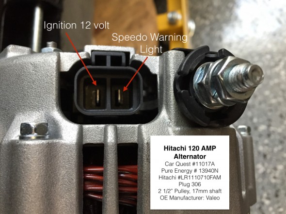
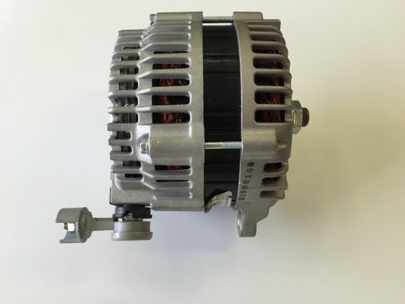
I am installing an alternator in lieu of the original dynamo/generator. The alternator I am using is an Hitachi manufactured by Valeo for the 2004-2008 Nissan Maxima. It produces 120 amps. Detail information:

Hitachi 120 AMP Alternator 

  • Car Quest #11017A
  • Pure Energy # 13940N
  • Hitachi #LR1110710FAM
  • Plug 306
  • 2 1/2” Pulley, 17mm shaft
  • OE Manufacturer: Valeo

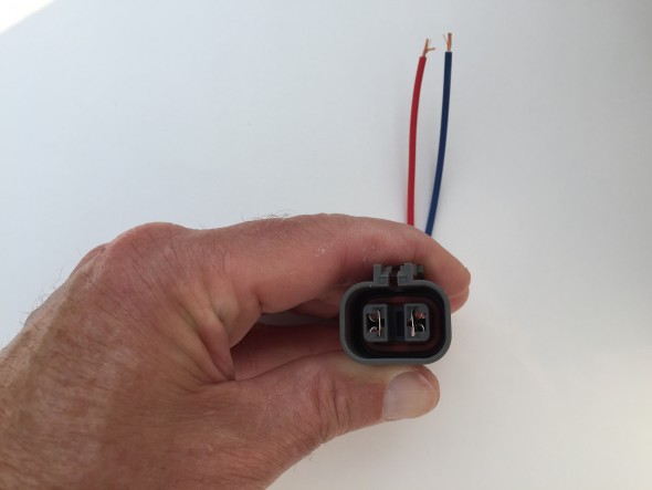
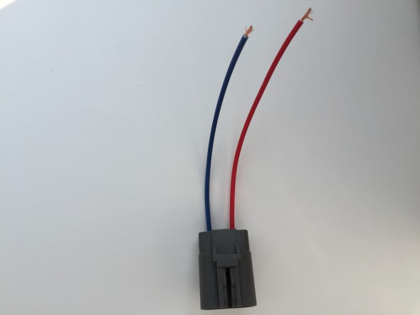
I ordered the Connector plug or “pigtail,” from National Quick Start Sales: http://store.alternatorparts.com/partnoc1900.aspx

Part # C1900 Hitachi, Mando, and Mitsubishi Alternator Wiring Repair Plug, Female. Alternator Wiring Harness Repair Connector with 2 Female Terminals

Being Japanese, the mounts for the alternator are obviously metric – and of different sizes! 18mm on rear bolt and 15mm on the front bolt with a 5/8″ wrench on both nuts.

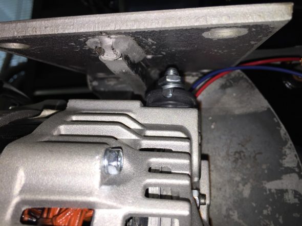
The power input post for the Hitachi alternator is, unfortunately for me, on the top of the alternator when it is mounted to the motor. In this position, the top of the post is only about 1/4″ from the bottom of the steal air conditioner compressor mounting bracket. This can be seen in the image below:

Alternator Power Post

Alternator Power Post

Obviously, this is not a good situation. Bill Rader, owner of Blue Sky Radiator and Electrical came to my rescue! He was able to place an adapter on the alternator that redirected to power post to the rear of the alternator thereby eliminating my problem.

Redirected Power Post on Alternator

Redirected Power Post on Alternator

Battery

To be determined.

Distributor

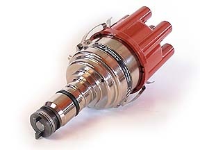
I had such good fortune with the Dutch “123” electronic distributor in my Big Healey, that I chose to use the same product in the MK2. The Jag does use a different model, number “Jag 6-R-V.” The unit offers 16 different advance-curves, that can be selected via a little switch. Information on the Forums suggests that the #1 or #2 advance curve may be the best to use with the 3.8 Jag motor with total advance of no more than 34 degrees. In our test runs of the engine we did NOT connect the vacuum line to the distributor. I will need to do additional research before settling in on a particular setting.

123 Electronic Distributor

123 Electronic Distributor


SPECIFICATIONS
direct. : CCW (topview)
voltage : 4,0-15,0 Volts
range : 500 – 7000 rpm
temperature : -30 to 85 Celsius
coil : stock or High Energy coil
  primary coil NOT below 1,0 ohm
dwell : constant current, fully autom.
time-out : after 1 second current is switched off
spark-bal. : better than 0,5 degr. crankshaft
vacuum : advance starts at 5 inchHg
  stops at 10 degr. @ 10 inchHg
  gearshift retard > 17 inchHg
max.advance : 45 degr. crankshaft
wiring : red = +6V or +12V, black = ‘-‘ coil


Installation instructions are available here:

123 JAG6 Distributor Installation Instructions

There is considerable debate in the Jaguar community about the the vacuum advance for the 123 distributor if used on the 3.8 engine. Some say to not connect the vacuum advance, others say to use the ported vacuum advance port on the carburetor, but my friend Mike Gassman, from Gassman Automotive has suggested that performance will be safely enhanced by using direct manifold vacuum. This article  written by a retired General Motors engineer corroborates Mike’s thinking. Ported Vacuum vs Manifold Vacuum.

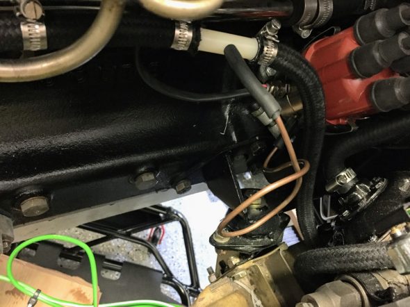
I am going to try the manifold vacuum for my project and see how the engine performs. I have decided to split the vacuum hose that connects the manifold and the brake reserve tank with a “T” connector. The smaller connection is then routed to the vacuum port on the 123 distributor. If you choose to do this, DO SO AT YOUR OWN RISK! Manufacturers would recommend against doing anything that might compromise braking vacuum but in my opinion, and that of others, the reserve tank provides more than ample vacuum pressure for the braking system.

Vacuum Line to Distributor

Vacuum Line to Distributor


Ignition Coil

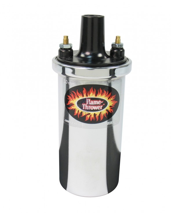
The original Lucas coil was replaced with a “Flame Thrower”  high output, 3.0 ohm, 40,000 volt, internally resisted unit made by Pertronix, model number 40501. The coil has such a prominent place on the engine that I wanted it to look nice with the polished cam covers. Consequently, I opted to go with the chrome case for the “bling” effect, but it is also available in black.

Pertronix Ignition Coil 40501

Pertronix Ignition Coil 40501

Ignition – Spark Plug Wiring

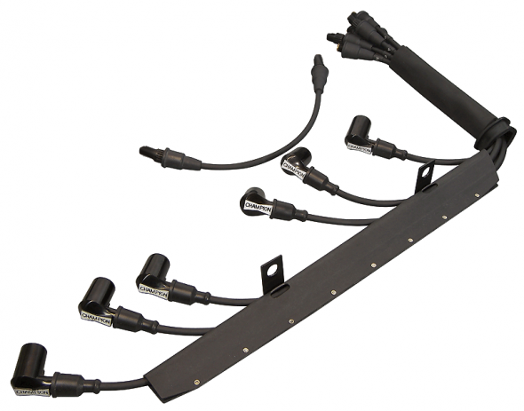
I elected to purchase a ridiculously expensive assembled wiring conduit kit for Pertronix ignition from XKs Unlimited using 7mm black wire. The spark plug and coil ends are pre-installed.

Spark Plug High Tension Wiring with Conduit

Spark Plug High Tension Wiring with Conduit

Spark Plugs

I am using NGK BPR5ES plugs with a 0.045 gap as recommended by Paul Salt on the Saloon-Lovers Jag Forum for solid wires with no resistors. BP5ES otherwise.

Starter

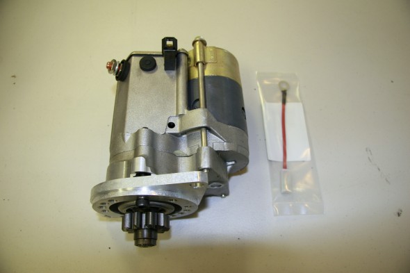
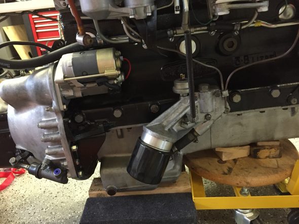
“High Torque” or “Gear Reduction” starters are available for the MK2 3.8. These starters are considerably smaller and lighter than the original Lucas starter, but more importantly they have considerably more cranking power. The starter can be set up to either use or eliminate the original starter solenoid and I decided to keep the original set-up. I sourced the new starter from SNG Barratt.

SNG Barratt High Torque Starter

SNG Barratt High Torque Starter

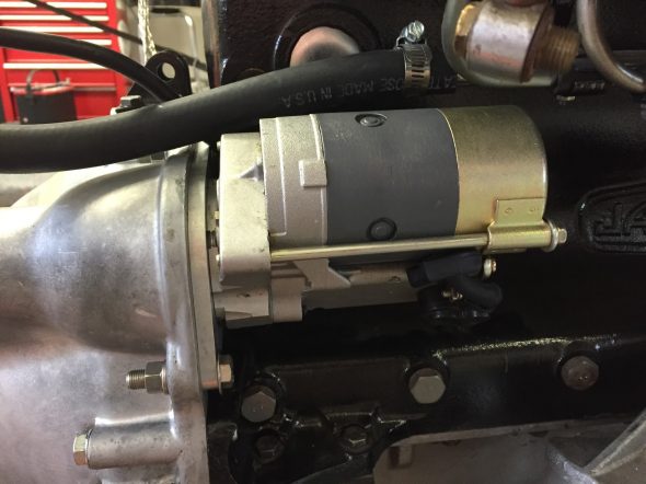
The starter is located on the right side of the engine and is secured to the bell housing with two 3/8″-24 x 1/12″ hex head bolts, flat washers and split washers. I am using the original starter solenoid on the firewall so it is necessary to connect the short jumper wire to the + terminal of the starter upon installation. Since it is a bit crowded once the starter is mounted I attached the cable from the starter to the starter solenoid before installation of the starter. A rubber boot was used to cover the terminal. It will be connected to the firewall starter solenoid after the engine is mounted in the car.

Starter Installed on Engine
Starter Installed on Engine

Starter Installed on Engine - Close-up

Starter Installed on Engine – Close-up
 

Starter Solenoid

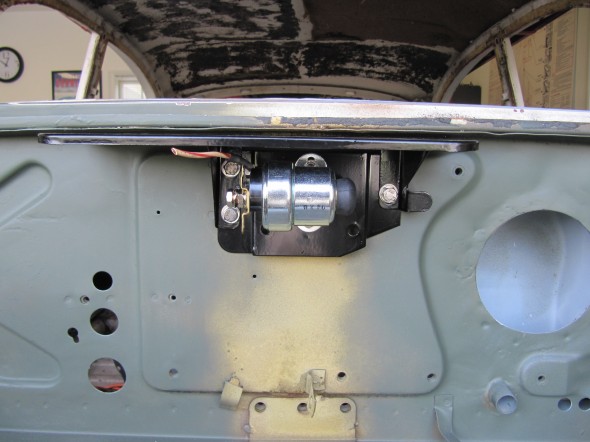
I am using a new reproduction solenoid. This is an image of a trial fitting of the solenoid on the Weather Protection Flange on the firewall.

Adaptor Plate Assembly for Solenoid and Solenoid Weather Protection Flange

Adaptor Plate Assembly for Solenoid and Solenoid Weather Protection Flange

Upgraded Brake Switch

I had planned to replace the MK2’s original hydraulic brake switch that activates the rear brake lights when the brakes are applied. The hydraulic switches currently available seem to experience a higher than normal failure rate. I encountered this same issue with my Austin-Healey 3000. In the Healey I replaced the hydraulic switch with a plug in the 4-way adaptor and installed a mechanical switch at the brake pedal. The wiring is the same as for the electrical switch. The mechanical switch was sourced from Watson’s Streetworks.

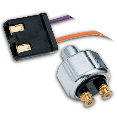
While I purchased the Watson’s switch to use in the MK2, I also found that Ron Francis Wiring sells an updated low pressure hydraulic switch that looks and mounts like the original. I decided to give this switch a try.

Ron Francis Hydraulic Brake Switch SW-32

Ron Francis Hydraulic Brake Switch SW-32

Horns

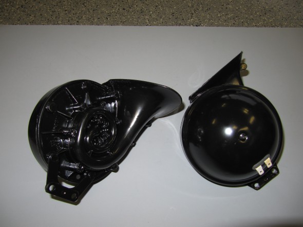
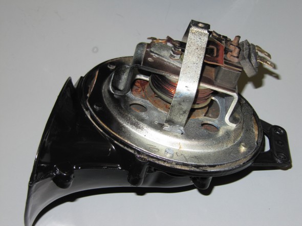
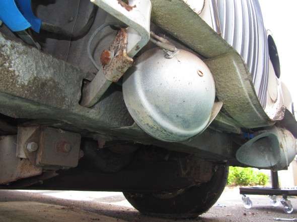
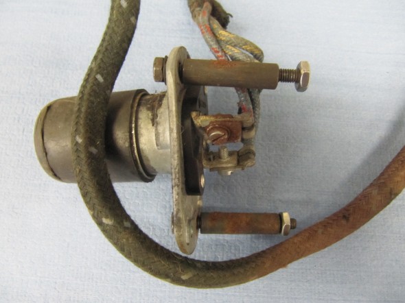
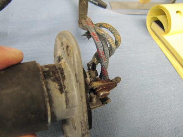
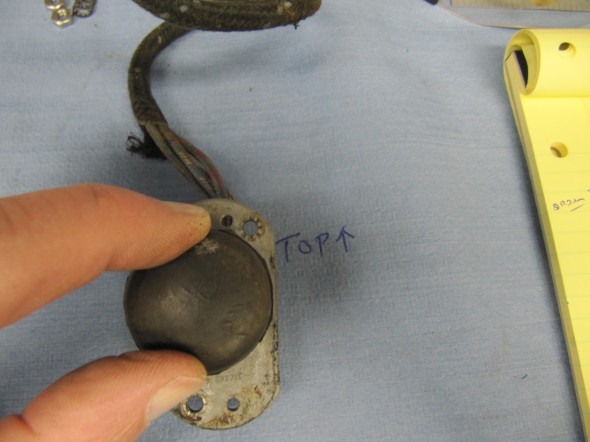
The horns are located at the front of the car and on either side of the engine compartment immediately below the radiator. My 1964 MK2 was equipped with horn model number WT (Wind Tone) 618U. I media blasted the two horns after stuffing the Flute with paper to avoid getting sand in the workings. I then took the domed covers off the high and low tone horns and painted each horn with POR-15 and overcoated with their spray Blackcoat product. I then sent the horns to E. Lawrie Rhoades, 7 Knollwood Rd, Medfield, MA 02052-2703 to have the electrical mechanism cleaned and tuned. Lawrie is a recognized expert on horn and wiper motor repair.

Horn Assemblies

Horn Assemblies

Horn Internals

Horn Internals

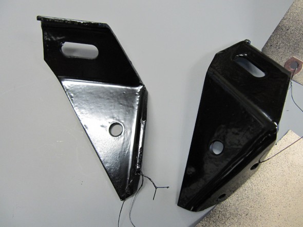
Horn Mounting Brackets

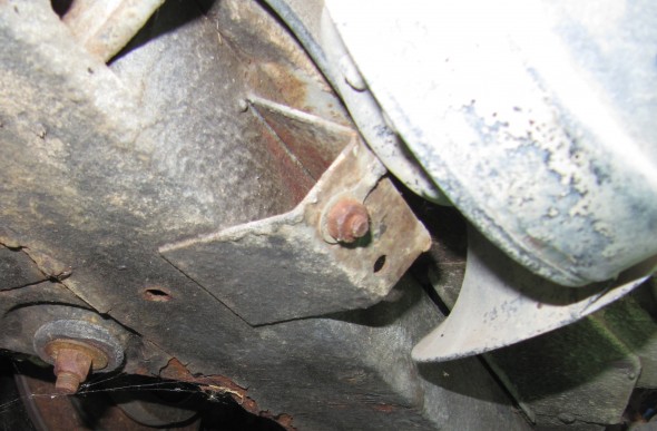
Both of the horn mounting brackets were also media blasted and painted with the POR-15 products. As the Service Manual indicates, the bracket is important in providing a ground to the horn, therefore, “Care should be taken in ensuring a good contact between the earth strap and horn bracket on the left hand horn.”  The horn is  secured to the bracket with two 1/4″ – 28 x  3/4″ hex head bolts with shakeproof washers and 1/4″ – 24 hex head nuts. The bracket is fastened to the bumper bracket with a single 3/8″ -24 x 7/8″ hex head bolt with both a flat washer and a shakeproof washer followed by a 3/8″ – 24 hex nut.

The LH Horn is the Low note horn and the RH Horn is the high note horn.

This image illustrates the connection of the ground wire to the car’s frame. the wire eyelet is fastened to the frame with a 1/4″ – 28 x 1/2″ hex head bolt, shakeproof washer and a 1/4″ -24 hex nut.

Horn Ground Wire

Horn Ground Wire

Horn Mounting Brackets

Horn Mounting Bracket

This image illustrates mounting and orientation of the horns below the radiator:

Horn Orientation

Horn Orientation

Headlamp Dipper Switch

The Headlamp Dipper Switch was in good condition and was cleaned for reuse. The switch is secured to the floorboard with two #10 – 32 x 1 7/8″ hex head bolts through distance pieces with shake proof washers. A rubber cap is pushed over the end of the foot switch.

The upper part of the switch base plate is the shorter side with the mounting screw hole offset to the right. This orientation is instructive for the proper location of the switch wiring on the three terminals. The terminal farthest to the right has the blue/red single wire, the lowest terminal (closest to the floor) has the single solid blue wire, and the left most terminal has two blue/white wires.

Headlamp Dipper Switch

Headlamp Dipper Switch

Dipper Switch Wiring

Dipper Switch Wiring

Headlamp Dipper Switch

Headlamp Dipper Switch

Headlamp Dipper Switch

Headlamp Dipper Switch

Renewed Dipper Switch

Renewed Dipper Switch

Renewed Dipper Switch

Renewed Dipper Switch


Direction Indicator/Headlamp Flasher

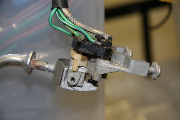
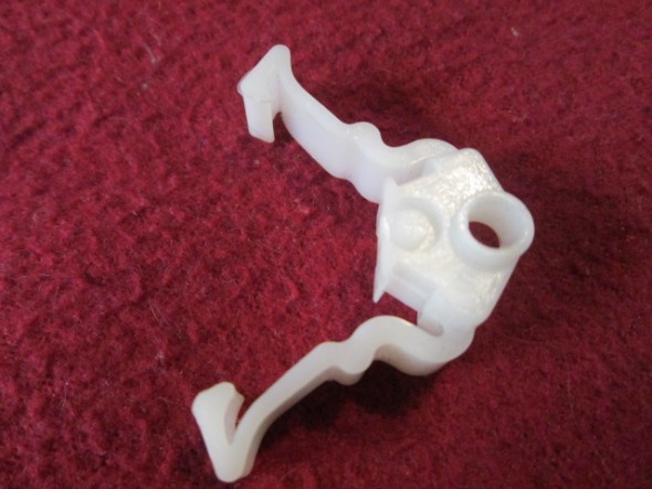
My MK2 has a Model 85 unit. I cleaned the assembly. The wiring appeared to be in very good condition but the nylon “spring” that catches the arm in the left or right position was broken.

Direction Indicator/Headlamp Flasher Switch

Direction Indicator/Headlamp Flasher Switch

Turn Indicator Flasher Side View

Turn Indicator Flasher Side View

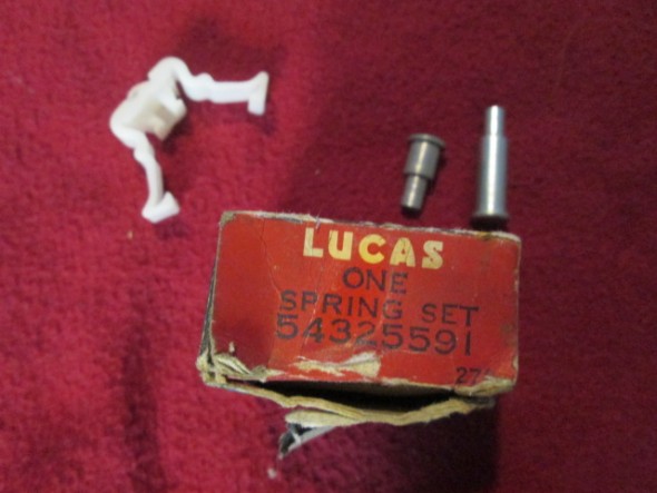
There was a time when Lucas made and sold repair kits to replace the nylon spring. Today they are a challenge to find but they do come up on ebay from time to time. I was able to purchase two of the repair kits. The kit includes the spring and the rivet used to hold the components together.

Lucas Turn Indicator Spring Set

Lucas Turn Indicator Spring Set

Turn Indicator Nylon Spring

Turn Indicator Nylon Spring

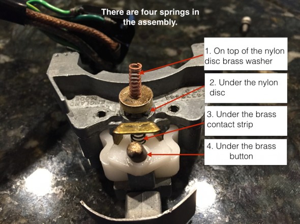
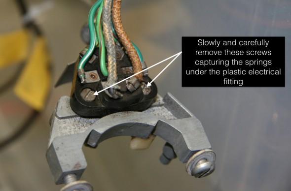
To replace the spring one removes two slotted screws from the plastic electrical fitting. This must be done carefully as there are a total of four springs between the aluminum housing and the plastic fitting.

Turn Indicator Springs

Turn Indicator Springs

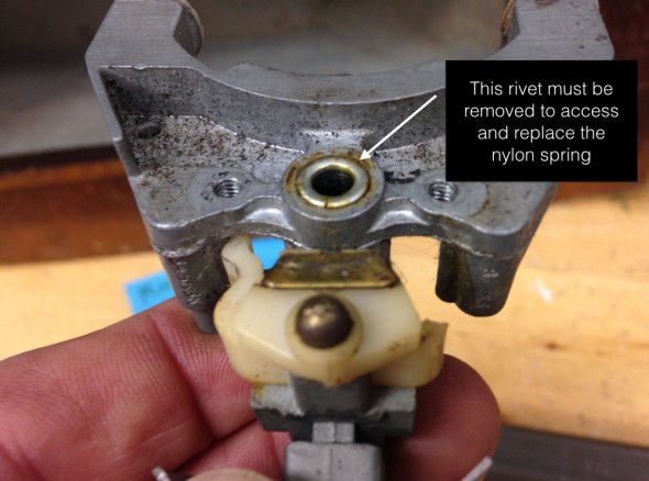
Once the electrical fitting is removed one has access to the rivet that must be drilled/cut out.

Turn Indicator Disassembly

Turn Indicator Disassembly

Turn Indicator Rivet

Turn Indicator Rivet

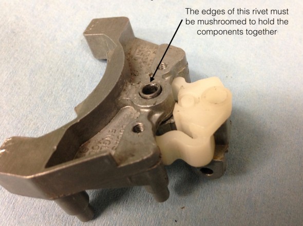
It is a tedious and somewhat challenging task to install the new rivet. I actually visited Mike Gassman of Gassman Automotive to help me with the install.

Turn Indicator Rivet

Turn Indicator Rivet

I held the assembly in place over a steel rod while Mike used several punches to get the job done. We didn’t do as well as the factory but we succeeded.

After placing all of the electrical contacts, springs and nylon/plastic components in their proper place one carefully places the black electrical fitting over the assembly and compresses carefully while a friend (spouse) inserts and tightens the two screws that hold the assembly together. This little piece consumed a lot of energy and time, but now functions as new!

Turn Signal Indicator Lights

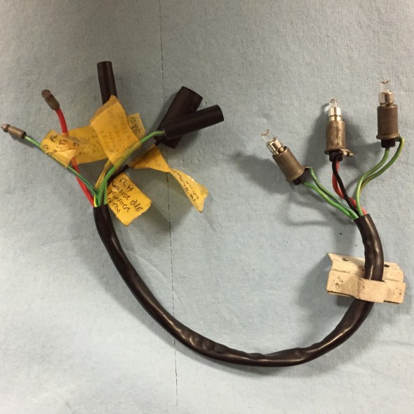
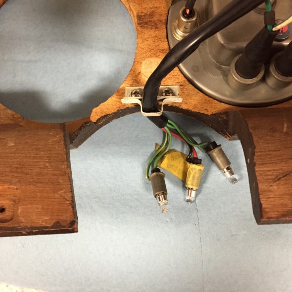
The MK2 used a short pigtail harness to connect the turn signal switch, the flasher relay and the indicator bulbs located on the steering column. My original harness was in very good condition and will be reinstalled after cleaning. Three warning bulbs are provided in the harness.

Turn Signal and Overdrive Indicator Bulbs, Holders, and Pigtail

Turn Signal and Overdrive Indicator Bulbs, Holders, and Pigtail

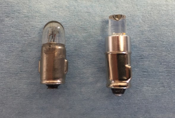
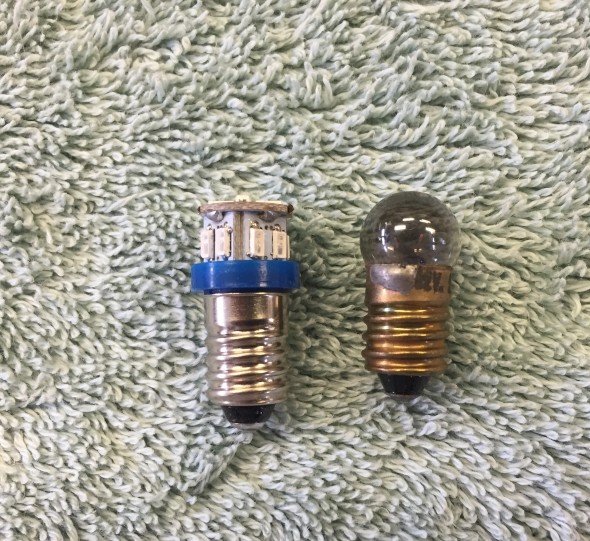
The LH bulb for the LH turn signal, the center bulb to indicate overdrive engagement and the RH bulb for the RH turn signal. The two turn signal indicator bulbs are replaced with green BA7 LED micro bayonet bulbs and the overdrive bulb is a clear white BA7. Bulbs were sourced from 4sightautomotive lighting at http://www.bettercarlighting.co.uk. This image shows the original bulb as well as the LED replacement:

2 Watt Liliput Turn Signal Indicator Bulb and Replacement BA7LED Green Micro Bayonet Bulb

2 Watt Liliput Turn Signal Indicator Bulb and Replacement BA7LED Green Micro Bayonet Bulb

I am also using LED flasher bulbs at each of the four corners of the car. Using the LED bulbs requires a LED flasher relay that is incorporated into the Classic Technologies Relay/fuse panel that I am using for my electrical system. The pigtail is held in place by a small bracket located on the backside of the LH Fascia Board Assembly and the bulbs plug into the Upper Switch Cover Assembly at Centre of Steering Wheel.

Turn Signal and Overdrive Indicator Bulbs, Holders, Pigtail and Mounting Bracket on LH Fascia Board Assembly

Turn Signal and Overdrive Indicator Bulbs, Holders, Pigtail and Mounting Bracket on LH Fascia Board Assembly

Overdrive Operating Switch

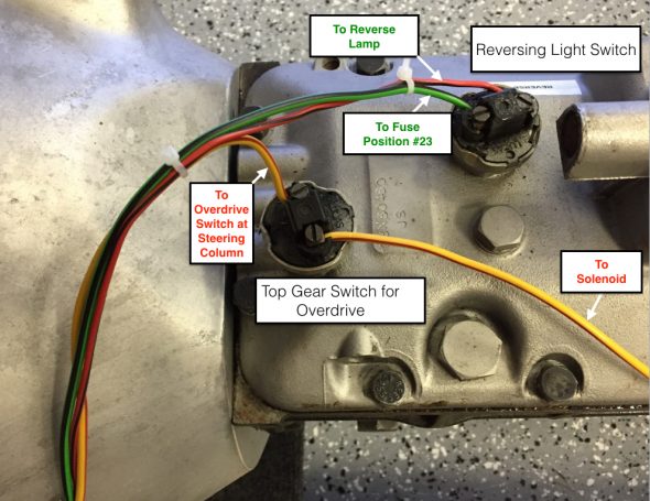
This switch which activates the electric overdrive is located on the right side of the steering column. Power is derived from fuse position #14 on the CT fuse box. With lever activation a signal is sent to the overdrive interlock, or top gear switch located on the top of the gearbox and then to the overdrive solenoid. A warning indicator bulb is illuminated when the overdrive is engaged.

Switch, on Gearbox Top Cover, Operating Reversing Light and Top Gear for Overdrive Unit

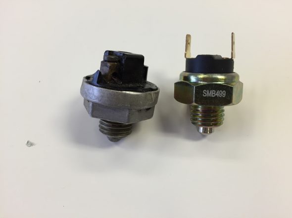
These two switches are identical. As indicated, both are located on the gearbox. I purchased new switches, but found after testing that both original switches worked fine so I left the original switches in place.

Overdrive Interlock or Top Gear Switch at gearbox

Overdrive Interlock or Top Gear Switch at gearbox

Original and New Lucas Overdrive and Reverse Switch

Original and New Lucas Overdrive and Reverse Switch

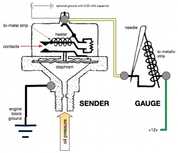
Oil Pressure Element

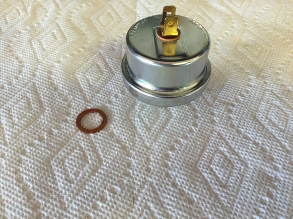
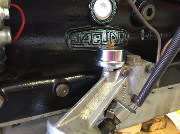
The Oil Pressure element or sensor is located directly above the Oil Filter Assembly on the RH side of the cylinder block. I replaced the element with a new Lucas item.Oil Pressure Element

Oil Pressure Element Mounted

Oil Pressure Element Mounted

Handbrake

 Handbrake

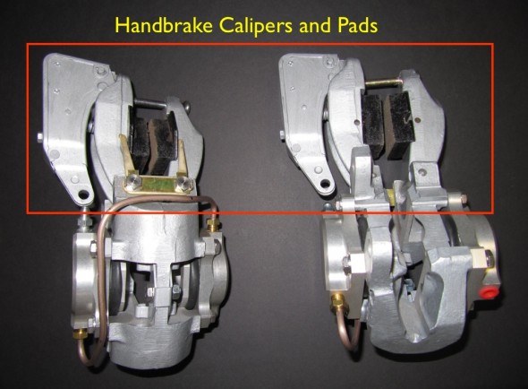
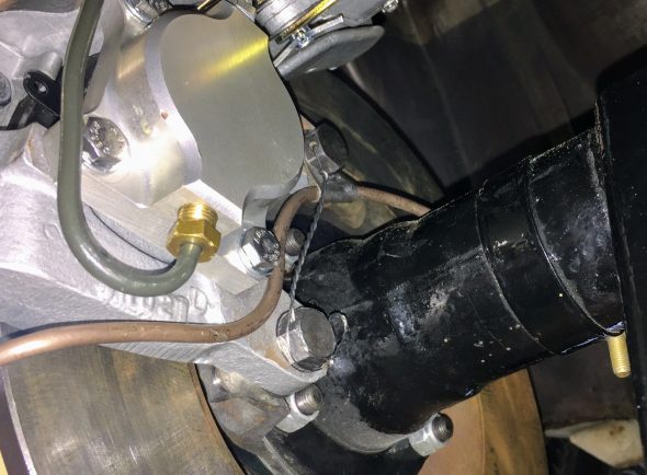
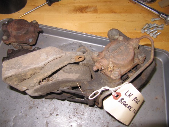
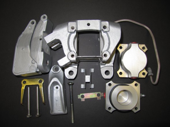
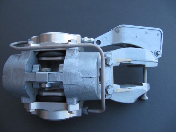
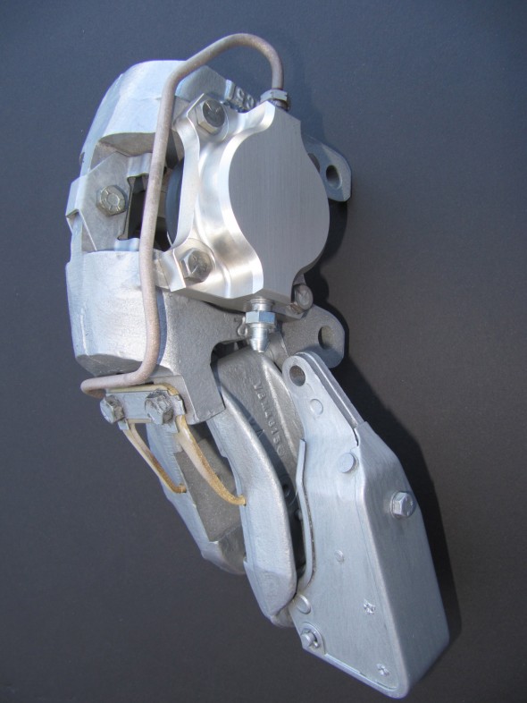
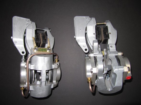
Handbrake Calipers

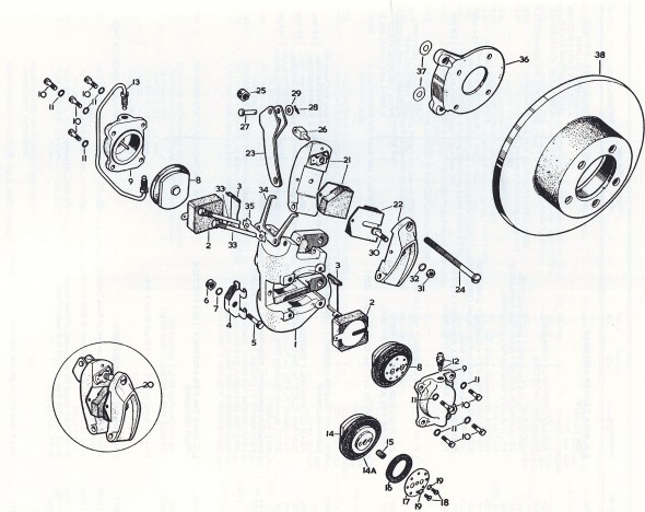
The mechanical handbrake unit is mounted on and above the caliper bodies on the rear brakes by means of pivot bolts and forked retraction plates. The Jaguar Service Manual states: “The handbrakes are self-adjusting to compensate for friction pad wear and automatically provide the necessary clearance between the brake discs and the friction pads.”

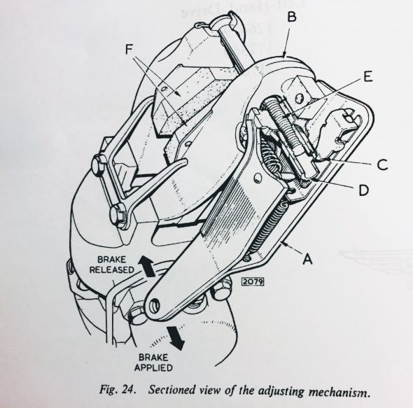
“When the handbrake lever in the car is operated, the operating lever (A) is moved away from the friction pad carrier (B) and draws the friction pads (F) together. Under normal conditions when the lever is released the pawl (C) in the adjusting mechanism returns to its normal position, thus the normal running clearance between the brake discs and the friction pads is maintained.”

“In the event of there being increased clearance, the pawl will turn the ratchet nut (D) on the bolt thread drawing the adjuster bolt (E) inwards and bringing the friction pads closer to the brake disc until the normal running clearance is restored.”

Handbrake Calipers

Handbrake Calipers

This image from the Jaguar Service Manual illustrates the adjusting mechanism of the “self-adjusting” handbrakes used on later model MK2s.

MK2 Handbrake Adjusting Mechanism

This is a great video done by [email protected] who rebuilt his XKE brake caliper assemblies: 

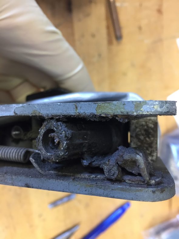
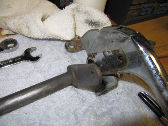
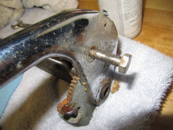
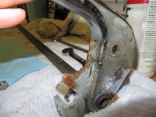
When I removed the cover from the handbrake lever I discovered globs of what I expect was fifty year old grease. The covers looked like they had never been removed. What a mess.

Handbrake Ratchet Nut and Spring Clip

The parts were working properly but did not rotate smoothly. I cleaned the components and applied some new grease for lubrication and reassembled the adjusting lever. 

In rebuilding my handbrake units, I kept the old pivot bolts that hold the handbrake calipers to the primary caliper body, but I did install new retraction plates, tab washers, friction pads, and adjuster bolts. 

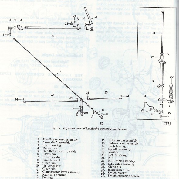
 Handbrake Schematic

Handbrake Components

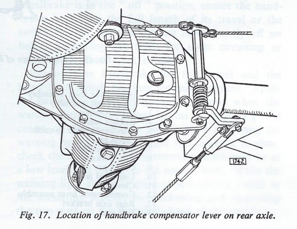
The Handbrake Compensator Lever is mounted to the rear axle case.

Handbrake Compensator Lever

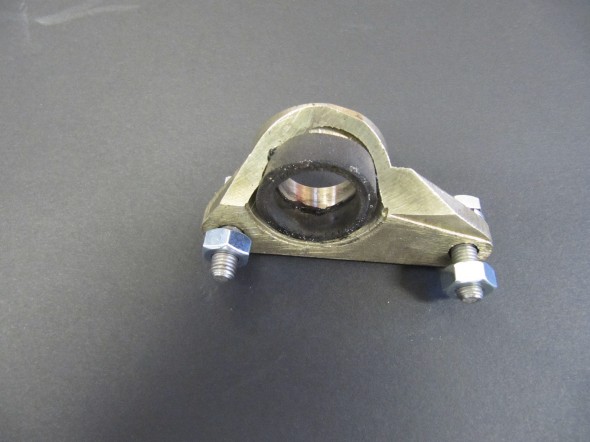
Housing for Handbrake Shaft

Housing for Handbrake Shaft

Housing for Handbrake Shaft

Housing for Handbrake Shaft

Housing for Handbrake Shaft

The housing is made of brass and has a rubber seal. It is mounted with two 1/4″ – 28 x 7/8″ hex head bolts with split washers. I cleaned up the housing and reglued the rubber seal.

Handbrake Compensator Lever

Handbrake Compensator

The Handbrake Compensator Lever assembly was a greasy and dirty mess, but I eventually got it cleaned up with the preloaded tension set. This was the “Before” as mounted to the rear axle differential:

Handbrake Compensator Assembly

Handbrake Compensator Assembly

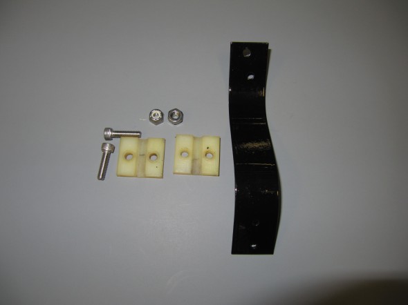
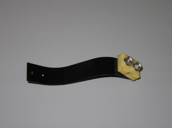
Handbrake Cable Support Bracket

The primary handbrake cable is supported by a bracket that is pop riveted to the underside of the floorboard. It consists of a thin metal strip with a nylon guide through which the cable travels. the nylon guide is secured to the guide with two #10 – 32 x 7/8″ bolts, flat washers and nylock nuts.

Supporting Bracket for Handbrake Cable

Supporting Bracket for Handbrake Cable

Supporting Bracket for Handbrake Cable

Supporting Bracket for Handbrake Cable

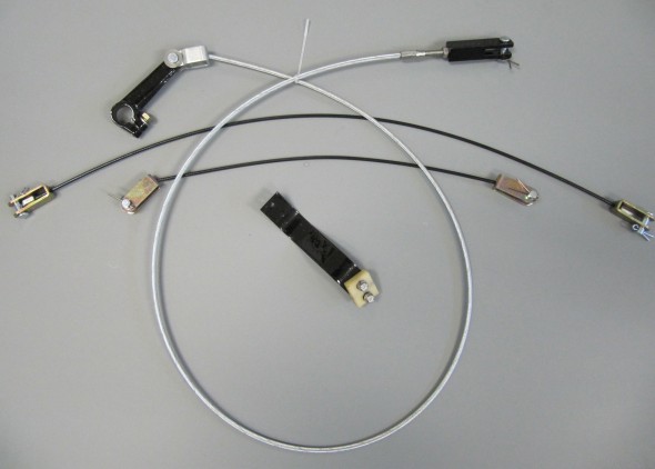
Handbrake Cables

The Handbrake cables were greasy and dirty, but otherwise appeared serviceable, but I decided to go ahead and replace them with cables sourced fromSNGBarratt.

Handbrake Cables and Components

Handbrake Cables and Components

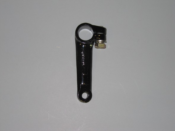
Handbrake Lever

The Handbrake Lever from the shaft to the primary cable was cleaned up and painted with POR-15. The clamping bolt to the shaft is a 5/16″ -24 x 7/8″ hex head bolt with a split washer.

Handbrake lever from Shaft to Primary Cable

Handbrake lever from Shaft to Primary Cable

 The Fork End of the Primary Cable

The Fork End at the Rear of the Primary cable was also cleaned and painted to use with a new primary cable.

Fork End at Rear of Primary Handbrake Cable

Fork End at Rear of Primary Handbrake Cable

Handbrake Lever/Handle Assembly

Disassembling, cleaning, and reassembling the handbrake assembly was fairly simple and straightforward. I have not, as yet, been able to source new components for the assembly such as the spring, button and small pin that hold the pin to the internal rod. Until I do, I have chosen to not completely disassemble the handle. I would like to do so to have it rechromed, but it is not in terrible shape. We will see what materializes.

Handbrake Assembly 7


Handbrake Assembly Components

Handbrake Assembly Components

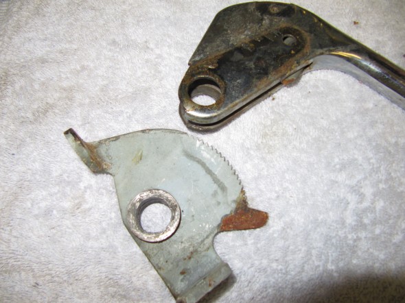
The pawl was a little rusty which I cleaned with the media blaster. I will definitiely send it away to have it re-zinced.

I first removed the cover plate, exposing handbrake pawl. This little piece was very rusty and it must be rechromed. It is held to the handle with two small self tapping screws that appear to be #2 x 1/4″. one of the screws was missing.

Cover Plate

Cover Plate

Cover Plate

Cover Plate

I then removed the chrome hex head bolt that held the handle, spring mechanism, pawl, the bracket operating the handbrake warning light switch and the shaft together. This was achieved by loosening the nylock nut. The bolt is a 5/16″ x 1 1/2″ special purpose bolt.

Brake Shaft

Brake Shaft


Handbrake Assembly Chrome Hex Bolt

Handbrake Assembly Chrome Hex Bolt

Handbrake Assembly Chrome Hex Bolt Removed

Handbrake Assembly Chrome Hex Bolt Removed

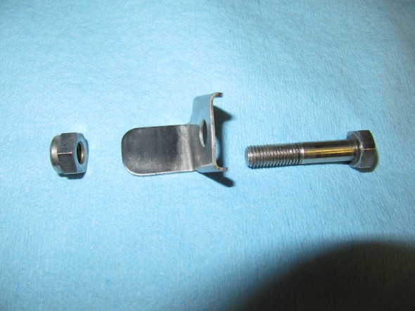
Chrome Hex Bolt, Nylock Nut, Bracket Operating Handbrake Warning Light Switch

Chrome Hex Bolt, Nylock Nut, Bracket Operating Handbrake Warning Light Switch

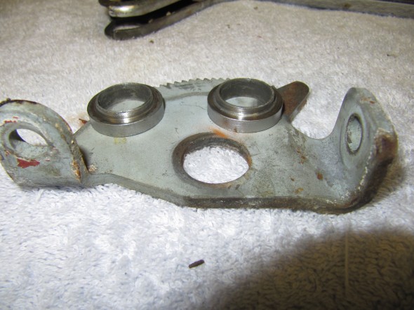
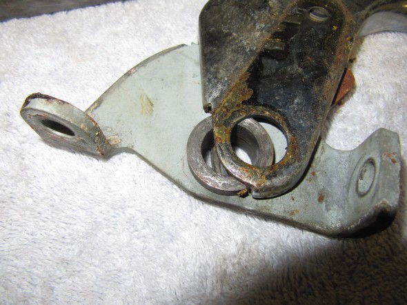
For lack of a better term, the pawl has two bushings with shoulders through which the handbrake shaft passes. These will be reused.

Pawl Bushings

Pawl Bushings

Pawl Bushings

Pawl Bushings

Pawl Bushings

Pawl Bushings

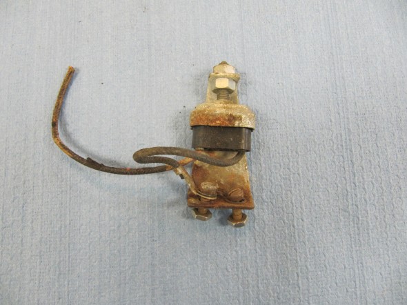
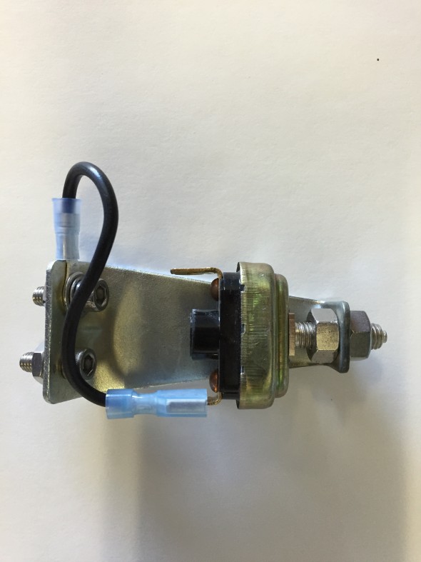
Handbrake Warning Lamp

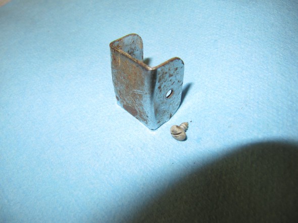
The MK2 has a warning light for handbrake activation. The Switch, At Base Of Handbrake Lever, Operating Handbrake Warning Lamp is mounted to the interior floor with a Bracket. I am replacing the switch itself with a new component. The switch is held to the bracket with two adjusting nuts. The bracket is mounted to the interior floor with two #10-32 x 1/2 cheese head machine screws and lock washers.

 Handbrake Warning Lamp Mounting Bracket and Switch

Handbrake Warning Lamp Mounting Bracket and Switch

Handbrake Warning Switch

Handbrake Warning Switch

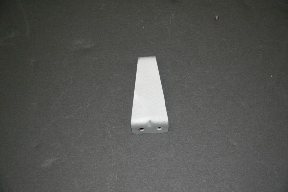
I media blasted the bracket and  zinc plated it for and reuse.

Handbrake Warning Lamp Switch Mounting Bracket

Handbrake Warning Lamp Switch Mounting Bracket

Handbrake System Installation

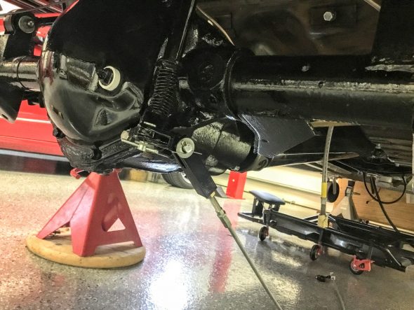
I began the installation by attaching the LH and RH compensator-to-caliper cables to the compensator. I used new cables sourced from SNG Barratt. The fork ends at one end of the cable are attached to the compensator balance lever with clevis and split pins as are the other ends to the handbrake calipers.

Handbrake Compensator Assembly with Cables

Handbrake Compensator Assembly with Cables


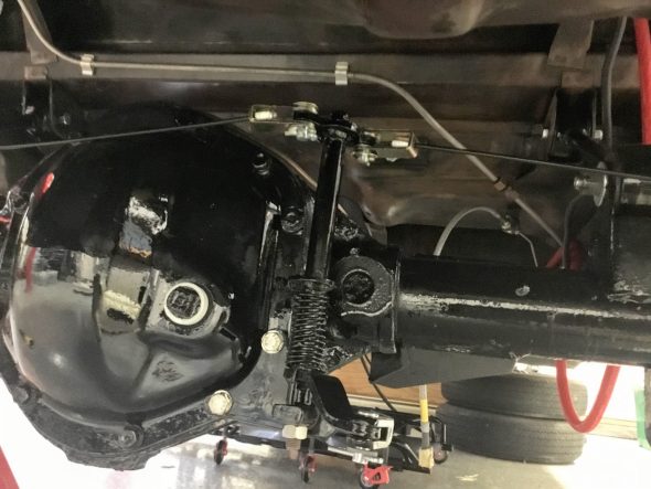
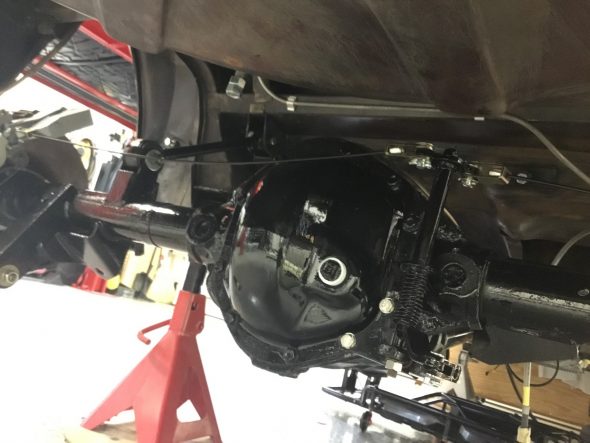
I then secured the pre-assembled handbrake compensator assembly to the rear axle. Two 5/16″-24 x 3/4″ hex head bolts with split washers are used to attach the assembly to the rear axle carrier through its cover. Note: These are coarse thread bolts, not fine thread as is typically used throughout the car! These two bolts are 1/4″ longer than the other cover mounting bolts to allow for the width of the compensator bracket. Sorry for the dark photo. It is a challenge to get contrast when everything is black.

Handbrake Compensator Assembly Mounted

Handbrake Compensator Assembly Mounted

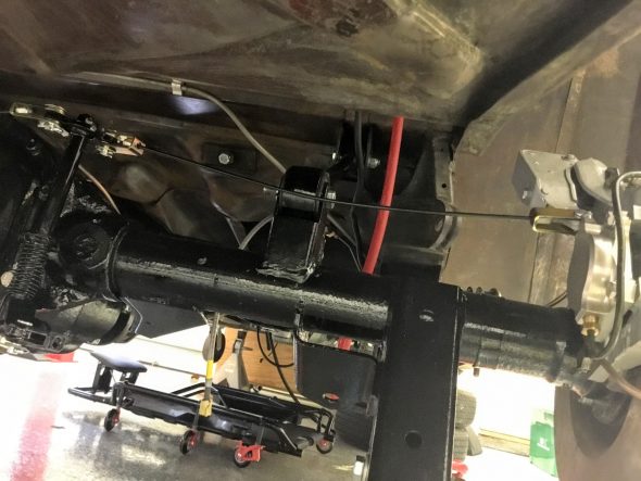
RH Handbrake Cable from Compensator to Caliper

RH Handbrake Cable from Compensator to Caliper

LH Handbrake Cable from Compensator to Caliper

LH Handbrake Cable from Compensator to Caliper

I then prepared the primary cable that runs from the handbrake shaft lever to the compensator. There is a fork end at the rear end of the primary cable that permits adjustment of cable tension. A universal jaw is then used to connect the fork and the compensator, locked in place with a clevis and split pin. I went ahead and connected the jaw end to the compensator.

Primary Cable from Lever to Compensator Assembly

Primary Cable from Lever to Compensator Assembly

Primary Cable from Lever to Compensator Assembly Mounted

Primary Cable from Lever to Compensator Assembly Mounted

The next step was to attach the housing for the handbrake shaft with its rubber seal to the propshaft tunnel. The housing is secured to the tunnel with two 1/4″-28 x 5/8″ hex head bolts into captive nuts on the inside of the tunnel.

Handbrake Shaft Housing

Handbrake Shaft Housing

One can then insert the splined end of the shaft through the housing.

Handbrake Shaft Splined End

Handbrake Shaft Splined End

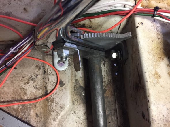
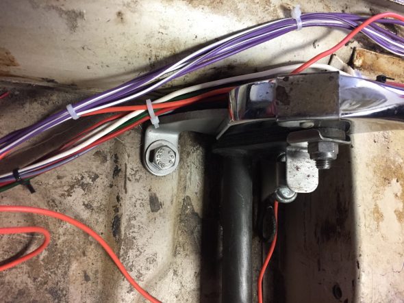
The handle end of the handbrake shaft is attached to the car floor and seat mounting crossmember with two bolts. The crossmember hex head bolt is 3/8″-24 x 3/4″ with a flat and split washer. The floorboard hex head bolt is 3/8″-24 x 1″. It goes through the mounting bracket and floor and is secured with a flat washer, and nylock nut. I found it easiest to install the handbrake first and then to install the handbrake warning light switch to the floor with the #10 machine screws. The seat crossmember bolt should be started initially and then the floor mount bolt.

Handbrake front mount bolt to seat crossmember

Handbrake front mount bolt to seat crossmember

Handbrake Floor Mount Bolt through Floor

Handbrake Floor Mount Bolt through Floor

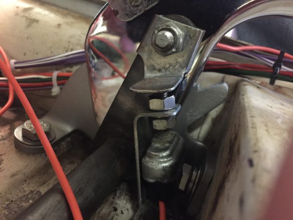
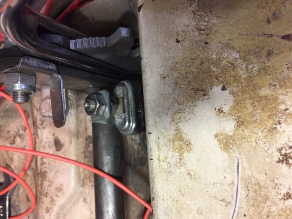
The handbrake warning light switch is depressed when the handbrake is not on. When the handbrake handle is pulled upward the switch is activated and the warning light illuminates.

Handbrake Warning Switch

Handbrake Warning Switch

Handbrake Warning Switch

Handbrake Warning Switch

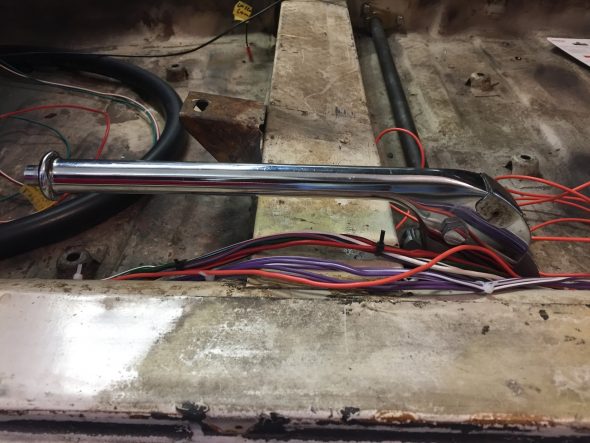
Handbrake Assembly Installed

Handbrake Assembly Installed

The handbrake lever previously mounted to the forward end of the primary cable was then slipped onto the splined handbrake shaft and the 1/4″-28 x 3/4″ hex head bolt was tightened to secure the lever to the shaft. 

Handbrake Lever Attached to Shaft

Handbrake Lever Attached to Shaft

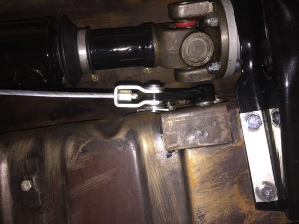
To keep the primary cable from fouling against the propshaft, Jaguar installed a supporting bracket that is pop riveted to the floor. Since I will be dismantling everything before painting, I used #6 machine screws to temporarily mount the support bracket to the underside of the body.

Handbrake Cable Support Bracket Mounted

Handbrake Cable Support Bracket Mounted

Handbrake Cable Support Bracket Mounted

Handbrake Cable Support Bracket Mounted

With the exception of final adjustment of the primary cable to achieve the proper tension, that completes the mounting of the handbrake system to the car.

Refitting the Handbrake Caliper Mechanism

I just followed the Service Manual instructions for refitting the handbrake calipers and friction pads. Although, as with most things, it is not quite as easy as it reads!  With the handbrake caliper assembly in your hand (friction pads installed), the adjusting bolt is screwed into the ratchet nut until their is a distance of approximately 7/16″ between the friction pads, that is, the thickness of the disc plus 1/16. The split pin is then refit through the handbrake caliper friction pad carrier and the adjuster bolt to hold it in place. The entire unit is then “dropped” over the disc rotor and in place on the primary brake caliper. The two pivot pins, retraction plates and tab washers are then installed. Yes, it can be a pain to get these pins aligned.

The directions indicate that one is to pull and release the operating lever at the caliper repeatedly when the ratchet will be heard to “click over.” This operation is repeated until the ratchet will not operate which will indicate that the correct clearance is maintained between the disc and the friction pads.

I then connected the cross cables with their clevis pins. With the handbrake lever in the full down (slack) position, I loosened the lock nut at the rear end of the main cable and then “adjusted the length of the main cable by screwing the threaded end of the cable into the fork end to a point just short of where the handbrake operating levers at the calipers start to move.” The cables will have some slack in them when the handbrake lever is in the rest position. 

I then tested the handbrake lever and found that I “locked-up” the rear brake rotors after six upward clicks n the handbrake pawl. I then made sure that I had all of the split pins installed and  I declared the system functional!  


Brakes MK2

The Front and Rear Brakes

The Jaguar MK2 uses a single line hydraulic system actuating disc brakes in both the front and rear of the car. While the four wheel disc brakes were “cutting edge” at the time of production for a four-door sedan, today, the braking action can be upgraded with vendor supplied modification kits. Front Brake Upgrade I decided to go with the Coopercraftbrake upgrade kit for the front and rear of the car. Up front, their four pot brake caliper range has been updated to include stainless steel pistons, a refined and improved caliper design for strength and efficiency. To gain some weight savings I installed the optional aluminum calipers. The system employs ventilated disc rotors that should help with cooling. No modifications were required for mounting. Every thing was a “bolt-on” application. Coopercraft provided fitting instructions with their kit:

Coopercraft Front Braking Installation Instructions

Coopercraft Front Braking Installation Instructions

Calipers and Pads

Calipers and Pads

Coopercraft Calipers

Coopercraft Calipers

The photos above show the upgraded EBC “Green Stuff” brake pads. After installing the vented rotors on the front suspension crossmember assembly I installed the calipers finding that it appeared that no shims would be needed for proper fit.  Two bolts secure each caliper to the stub axle housing lugs: The shorter 1/2″ x 1 1/8″ – 20 is at the upper mount and the longer 1/2″ x 2 5/8″ – 20 is at the lower mount. Each bolt is accompanied by a flat washer and a split washer. The cad plated brackets were used on the original brakes to support the union of the rubber brake hose to the metal caliper pipe. With the Coopercraft upgrade these are not used, as the hose links directly to the caliper.
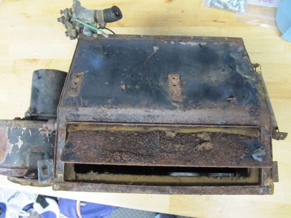
However, I found that sliding the EBC pads into the caliper, on either side of the rotor, was difficult and the concluding fit was much tighter than I liked. After checking with Coopercraft, they advised that the EBC pads are about 2mm wider than the standard pads. I volunteered that while I was looking for an “upgraded” braking experience, I was not going to be racing the car. They suggested that I might want to go with standard pads rather than the EBC pads. They also recommended that if I was going with standard pads in the front brakes that I should do the same with the rear brakes. Oh well, just wasted money once again!

I ordered standard front pads to fit a Series II/III E-Type (the proper pad to fit the upgraded alloy calipers) JLM 9515 as well as standard pads for the rear 10821* from SNG Barratt and they fit just as they should. Wish that I had ordered the Mintex pads to begin with!

Coopercraft Vented Rotors, Alloy Calipers fitted with Goodridge Stainless Brake Hose and Hubs installed
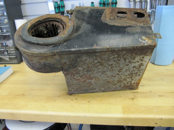
Coopercraft Vented Rotors and Alloy Calipers with Standard Mintex Pads and Hubs Installed
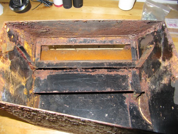
Anti-rattle clips are added after the pads and pins are installed. These spring clips are part number 12292 and a total of four are required.

Anti-Rattle Spring Clips for Brake Pads Installed

Mintex Front Caliper Brake Pads


I replaced the original rubber brake hose with Goodridge stainless hoses. The larger fitting on the end of the hose is metric, 16 mm diameter – .50 with with a 16mm -.50 nut.

Goodridge Stainless Brake Hose

Goodridge Stainless Brake Hose

After mounting the calipers I safety wired the caliper mounting bolts. 

Stainless Safety Wire and Twist Tool

I used 19 gauge wire that is probably a little heavier than needed but it worked just fine. If you are doing safety wiring, it can certainly be done with regular pliers, but the twist tool gives a very nice uniform appearance to the wire and is easy to use. 

Safety Wire on Front Brake Calipers

No videos are perfect, but this short video gives you a pretty good look at how safety wiring should be done. There is sound but screen captions are used initially.

Rear Brake Upgrade

In the rear, the Coopercraft upgrade kit consists of four redesigned and uprated cylinders, incorporating stainless steel pistons in an alloy caliper. This kit utilizes the standard handbrake mechanism and is designed to maintain a good balance with their uprated front sets. As stated previously, I did not use the EBC pads and instead substituted the standard pad provided by SNG Barratt.

Alloy Rear Brakes

Alloy Rear Brakes

Rear Brake Friction Pads

The small tabs with holes in each brake pad is to permit the insertion of a hooked wire to pull the pad out when it is replaced. The pads are held in place by the Retaining Plate for Friction Pads as seen below with mounting hardware.

Rear Brake Friction Pad Retainer with Fasteners

The image below shows the Coopercraft Alloy Pistons and Housings installed in the original calipers with new pads secured by the pad retainer. 

RH Rear Brake Caliper with Retaining Plate for Friction Pads Installed

The calipers need to be centered around the rotors and this is accomplished with the use of shims on the two bolts securing the calipers to the axle. On my car, I use five .010″ shims on the upper bolt of the RH caliper and five .010″ shims on the lower bolt. On the LH side, I used no shims on the upper bolt and two .010″ shims on the lower bolt.

Following assembly, I safety wired the mounting bolts for both rear calipers.

Safety Wired Rear Calipers

A warranty is also provided by Coopercraft:

Coopercraft Brake System Warranty and Liability

Coopercraft Brake System Warranty and Liability

Rear Brake Caliper Rebuild

Rear Brakes

Rear Brakes

In addition to adding the new Coopercraft Piston/Cylinder Sub-Assemblies I completely rebuilt the Rear Caliper Assemblies including the Handbrake Calipers. As the image below illustrates the original silver color was long gone!

Left Rear Brake Caliper

Left Rear Brake Caliper

To disassemble the calipers, I first separated the handbrake calipers from the primary caliper. To do so, I bent back the tabs on the Tab Washer and unscrewed the two Bolts, Securing Handbrake Mechanism to Rear Calipers. I then removed the Retraction Plate Fork that permitted the removal of the LH and RH Handbrake Pad Carrier Assembly with the friction pads. The Bolt, Securing Pad Carriers to Operating Lever was then unscrewed separating the two Carriers. I then removed the Support Plates for friction pads which simply fit into slots on the caliper body. Four 1/4″-24 x 7/8″ hex head bolts with shakeproof washers secured each Piston/Cylinder Assemblies. These were removed and the assemblies with the friction pads were removed. The Retaining Plate for friction pads was held in place with a 1/4″ – 24 x 7/8″ hex head bolt. It was removed and will not be replaced until the caliper is mounted and the new friction pads are installed. The Bridge Pipe Assembly and the Bleed Screw and Ball Assembly were removed from the Piston/Cylinder Assemblies and replaced with a new pipe and fittings. All components were then media blasted or otherwise cleaned and painted with Eastwood’s silver ceramic caliper paint. New bolts and screws were installed along with new friction pads.

LH Rear Brake Caliper Components

LH Rear Brake Caliper Components

Right Rear Brake Caliper Refurbished

Right Rear Brake Caliper Refurbished

Right Rear Brake Caliper Refurbished

Right Rear Brake Caliper Refurbished

Rear Caliper LH & RH

Rear Caliper LH & RH


zz


Gearbox, Clutch and Propshaft

Clutch and Gearbox

Clutch Master Cylinder

I will replace the master and reservoir seen here with a new unit.

Clutch Master/Reservoir

Clutch Master/Reservoir

Clutch Master/Reservoir

Clutch Master/Reservoir

Since the clutch master and the brake master share the same housing and pedal box, information about those components is addressed under the brake servo and hydraulics post at this link: https://valvechatter.com/?cat=615

Clutch Master Cylinder, Reservoir Mounted to Housing with new Pedal Rubber

Clutch Master Cylinder, Reservoir Mounted to Housing with new Pedal Rubber

Bracket for Flexible Clutch Hose at Rear of Cylinder Head

This little bracket is in a conspicuous location and called for re-chroming.

Clutch Flexible Hose Bracket at Rear of Cylinder Head

Clutch Flexible Hose Bracket at Rear of Cylinder Head

Slave Cylinder Hydraulic Pipe

A hard line attaches to the flexible stainless steel hose at the cylinder head bracket (shown above) and connects to the slave cylinder. It is held securely by one clip attached to the bell housing. The new line was sourced from Classic Tube along with the pre-bent brake lines.

Slave Cylinder Hydraulic Line

Slave Cylinder Hydraulic Line

Clutch

The 1964 MK2 used a spring-loaded, hydraulically-operated, driven plate assembly with cover and a graphite release bearing. Later models switched to a diaphragm clutch. While the diaphragm cultch is probably easier to operate, I decided to stick with the original type in my restoration. The entire clutch assembly was purchased from SNG Barratt and installed by my engine builder, Mike Gassman, from Gassman Automotive. The unit was balanced with the engine for smoother running.
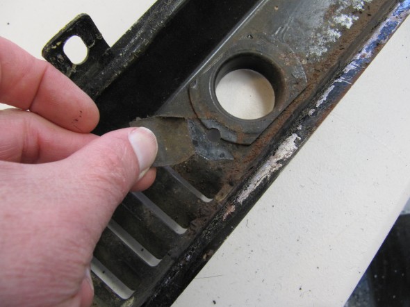
MK2 Clutch Diagram

MK2 Clutch Diagram

MK2 Clutch Assembly

MK2 Clutch Assembly

Release Bearing and Clips

Release Bearing and Clips

Release Bearing Mounting Clips

Release Bearing Mounting Clips

Clutch Slave Cylinder

Fortunately, the replacement slave cylinder sourced from SNG Barratt is exactly the same as the original. the rubber boot is somewhat different, but otherwise identical. The new return spring is; however, shorter than the spring currently on the car. Not sure if it is a different spring or if the original is stretched. In any case, I shall try the new one (which did have the proper Jaguar part number) and see how everything functions.

Slave Cylinder Assembly

Slave Cylinder
Assembly

The Jaguar Service Manual states that “there should be 3/4″ free travel or unloaded movement at the pedal pad before feeling the resistance of the clutch thrust springs. The free travel is most easily felt by depressing the pedal pad by hand until a marked resistance is felt. Adjustment is effected by slackening the lock nut and turning the operating rod between the slave cylinder and the clutch withdrawal lever. Screwing the rod into the knuckle joint will increase the pedal travel; screwing the rod out will decrease the free travel.”

MK2 Clutch Slave Cylinder Adjustment

MK2 Clutch Slave Cylinder Adjustment

Gearbox and Overdrive The gearbox is a four-speed type with synchromesh on the second, third, and top gears. The overdrive is a Laycock de Normanville. First and reverse gears are 12.731:1, Second is 7.012:1, Third is 4.836:1, and fourth is 3.77:1; with the overdrive engaged the top gear ratio is 2.933:1. A synchronized fiord gear was added later in production.

According to Nigel Thorleys excellent book – Original MK1/MK 2 the all synchro box was fitted in Sept 1965 from chassis no 119200 – 2.4 RHD 127822 – 2.4 LHD 169341 – 3.4 RHD 180188 – 3.8 LHD

MK2 Gearbox

MK2 Gearbox


MK2 Overdrive

MK2 Overdrive

Mike Gassman, http://www.gassmanautomotive.com refreshed the overdrive and the gearbox was sent to Quantum Mechanics in Connecticut. Both units were in good repair with the exception that the 3rd to fourth shift fork was bent and was replaced. The gearbox also had all bearings, synchronizers, seals and gaskets replaced. The gears were in good shape. The overdrive was cleaned, an overdrive rebuild kit installed and reassembled in good working order. A new solenoid was affixed and the system was tested.

Change-Speed Lever Assembly (Gear Shift) The  change-speed lever has single flat washer above the selector lever.

There is a two part rubber bush inside the selector lever through which the selector shaft passes. There is a flat washer at each end of the bush. The washers have different diameter holes appropriate to the shaft size at each end of the lever. I cleaned the selector lever and painted it with POR-15. New rubber bushes were also installed.

Change-Speed Lever

Change-Speed Lever

Selector Lever

Selector Lever

Painted Selector Lever

Painted Selector Lever

Assembly Components

Assembly Components

There is a bronze bushing in the selector lever through which the pivot pin passes. This bush was also replaced with a new component. A new fiber washer is located on each end of the pivot pin. A double spring washer  is located on the pivot pin and the assembly is held together with a slotted nut and a split (cotter) pin.

Change Speed Lever Knob

Change Speed Lever Knob

The correct lever knob for the early Moss gearbox (without first speed synchro) is a tear drop shape. The later box used a round shifter ball. A locking nut secures the shift knob to the shaft.

I ordered a new lever shaft and discovered that what is being supplied now is 3 inches shorter than the original. I will probably have my original lever shaft rechromed and use it.

Original Shifter on Left and New Part on Right

Original Shifter on Left and New Part on Right


Pivot Jaw Holding Selector Lever

This device connects the Change-speed Lever (gear shift) to the Gearbox Top Cover. In the image below it is the black yoke which was cleaned and painted with POR-15.

Pivot Jaw Housing Selector Lever

Pivot Jaw Housing Selector Lever

The following image shows the components of the Pivot Jaw assembly: The Pivot jaw, two fibre washers, a bushing, a flat “D” washer, a spring washer and a slotted nut with split pin.

Pivot Jaw Assembly Components

Pivot Jaw Assembly Components

This image shows the Pivot Jaw Housing, the Change-speed Lever, and the Selector Lever all assembled and in place on the gearbox:

Assembled Gear Selector Assembly

Assembled Gear Selector Assembly

Fasteners for Gearbox to Engine The original fasteners were in good shape, no doubt due to the thick coat of oil and grease that encapsulated them! I media-blasted the bolts and nuts and had them zinc plated for use upon reassembly. There are eleven hex head bolts 3/8″ – 24 x 2 7/8″ with two 3/8″ – 24 nuts and shakeproof washers, and four 3/8″ – 24 x 1 3/8″ hex head bolts with four 3/8″ – 24 nuts and shakeproof washers.

Bellhousing fasteners

Bellhousing fasteners

Cover Plate at Front of Clutch Housing  The cover plate is fastened to the engine backplate with four #10-24 x 1/2″ hex head bolts and shakeproof washers. It is installed when the gearbox is mated to the engine when the two components are separated by approximately 2″. At that time the cover plate is slid into position and tightened against the lip of the gearbox bell housing with the four bolts.

Clutch Cover Plate

Clutch Cover Plate

Clutch Cover Plate at Bell Housing

Clutch Cover Plate at Bell Housing

Gearbox/Engine Mating

On June 18, 2016 in preparation for the preliminary installation of the engine and gearbox into the car for testing, I mated the two components together using the bolts referenced above. In the cases where nuts are used, all nuts are found on the bell housing side. I had to wrestle with the gearbox a bit to get it to seat properly, but I eventually got there. One must be careful to keep the gearbox mainshaft level with the crankshaft to avoid bending the shaft.

Gearbox Mainshaft

Gearbox Mainshaft

I used my engine hoist to hold the gearbox at proper height during the exercise. Several long 3/8″ bolts were used to align the bell housing and the backplate of the engine, prior to inserting the proper bolts and pushing the gearbox home. As mentioned above, then the two components are approximately two inches apart, the clutch cover needs to be inserted and bolted in place.

RH Side of Bell Housing Mounted to Engine

RH Side of Bell Housing Mounted to Engine

LH Side Of Bell Housing Mounted to Engine

LH Side Of Bell Housing Mounted to Engine

Ground Strap

The ground strap was connected to the engine/bell housing prior to installation in the car. A new ground strap was sourced from SNG Barratt. Note the proper location of the strap:

Ground Strap Mounted

Ground Strap Mounted

Propshaft

The propshaft with the two flange yokes attached is just under 48″ long. The shaft seems to be in good shape, but I went ahead and replaced the two universal joint journals and bearings. Following installation of the universal joints I greased the two units and then cleaned the shaft well to send to Driveshaft Specialists in San Antonio, TX  http://www.driveshaftspecialist.com  (Jeff, 866-455-6622) for balancing.

Universal Joint Replacement

Universal Joint Replacement

Duralast Universal Joints

Duralast Universal Joints

Universal Joints Installed

Universal Joints Installed

Upon return from Driveshaft Specialists, I painted the propshaft with POR-15.

Propshaft with new Universal Joints

Propshaft with new Universal Joint

Balanced & Painted Propshaft

Balanced & Painted Propshaft

Gearbox/Overdrive Lubrication

After installing the engine and gearbox in the car I filled the gearbox and overdrive with oil. Mike Gassman, at Gassman Automotive, recommended using Amalie Elixir Full Synthetic GL-5 Gear Lubricant. The Jaguar MK2 Service Manual indicated that 4-3/4 pints of lubricant should be used.

Amalie Elixer Full Synthetic GL-5 Gear Lube 75W-90

This image, although a little out of focus, shows the fill plug near the top and the drain plug at the bottom of the gearbox. The overdrive fills though an internal hole from the gearbox to the overdrive.

Drain and Fill Plugs for the Jaguar MK2 Gearbox

While I could have used my hand pump to pump the gear lube from below into the fill hole, since my interior is not installed I removed the fiberglass gearbox cover and filled from above. I inserted a clear tube into the fill hole and routed it to the interior. I found that it actually took a little closer to 4- 1/2 pints to fill the units, even after waiting some time to allow the fluid to flow to the overdrive. I filled the gearbox until the gear lube began to leak out of the fill hole.

Fill Tube for Gearbox


Gauges, Instruments and Switches

Gauges, Instruments and Switches

Smiths and Lucas

Lucas was the primary provider of things electric incorporated in the Jaguar MK2 and for that matter most other British cars of the period. Smiths, another British automotive parts manufacturer produced instruments/gauges, heaters, clocks and radios among other components. Eric Kriss, a fellow MK2 restorer, has an excellent history of the relationship of Lucas and Smiths on his Blog: http://fairislepress.com/WP/?p=3736.

The speedometer and tachometer are located immediately behind the steering wheel directly in the driver’s view. Most of the other gauges, instruments and switches are located in the Instrument Panel Assembly in the center of the interior’s dash.

I sent all of my instruments to Nisonger http://www.nisonger.com for cleaning, calibrating and refurbishing where necessary.

Tachometer

Nisonger converted the tach to a negative ground electronic tachometer. These are the instructions for installation:Nisonger Electronic Tach Instructions

Clock

On the MK2, the clock is located inside the tachometer. I removed the clock (loosening two machine screws on the back of the clock/tachometer) and sent it to Mike Eck,  [email protected] to have repaired as it was not functioning. He  also convert the clock to negative ground.

Clock/Tach

Clock/Tach

Clock/Tach

Clock/Tach

Speedometer/Speedometer Cable

I gently cleaned the speedometer and mailed it to Nisonger with the other gauges. It came back in beautiful condition.

Speedometer

Speedometer

As part of the preliminary install process I added the new speedometer cable – 96″ variety in the engine bay. It is secured by one clip just above the steering column. It is then routed over the top of the gearbox to the passenger side of the car. I have researched how the cable is to be properly secured under the car as it routes to the fitting on the gearbox, but as of December 2016 I have yet to learn anything definitive.  Consequently, I have temporarily zip-tied the cable to the fuel line along the passenger side chassis rail as seen below. The objective is to mount the cable in such a way that it has direct unimpeded access to the gearbox fitting with no cable binding. 

Speedometer Cable Install

Speedometer Cable Install

Speedometer Cable Mounting

Speedometer Cable Mounting

Instrument Panel Assembly

Instrument Panel Assembly

Instrument Panel Assembly

In numerous Jaguar models the interior designers incorporated a handsome centrally-located gauge and switch panel. The panel is made of pressed steel with a copper bath and is hinged at the lower edge of the panel. The hinges are mounted to fixed nuts in the bodywork by four 1/4″-24 x 1/2″  hex head bolts with shockproof and plain washers. Loosening two thumbscrews at the top of the panel makes it possible to easily rotate the panel to access the wiring for the gauges and switches at rear of the panel.

Instrument Panel Assembly Face

Instrument Panel Assembly Face

Instrument Panel Assembly

Instrument Panel Assembly

Following the removal of all of the toggle switches and instruments I cleaned the panel assembly. Amazingly the vinyl material on the face of the panel was in very good shape. However, I decided to replace it with a similar material sourced from Aldridge Trimmers in the UK. I did so because I plan to cover the mounting panel for the air conditioning central vents, located immediately below the instrument panel, with vinyl and I want the materials on the two panels to match. The vinyl was secured to the panel with 3m Super 77 spray adhesive.

While not the same as the original Rexine Leathercloth, the grain is almost identical. Eric Kriss researched the Rexine product determining that is was made by Rexine Ltd. of Hyde, England. The leathercloth was actually cloth “impregnated with cellulose nitrate, camphor oil, pigment and alcohol and then embossed to look somewhat like leather.” Eric located this wonderful advertisement for Rexine:

Im19291011LC-Rex


The lighting and identification label strip for the toggle switches is comprised of several components.These images show the diffuser screen after clean-up.

Diffuser Screen

Diffuser Screen

There are three bayonet style bulbs spaced evenly along the bottom of the panel assembly. I have replaced these incandescent bulbs with BA7 LEDs.

2 Watt Liliput bulb and replacement BA7LED white micro bayonet bulb

2 Watt Liliput bulb and replacement BA7LED white micro bayonet bulb

This is an image of my finished instrument panel assembly showing the new vinyl, restored gauges and switches:

MK2 Instrument Panel Assembly

MK2 Instrument Panel Assembly

As one can see, the panel includes four gauges: an electric water temperature gauge, an electric oil pressure gauge, an electric fuel gauge and a voltmeter. The car originally had a ammeter in the place of the voltmeter, but since I converted my car from the original dynamo (generator) to and alternator it made much more sense to install a voltmeter to monitor the electrical system.

Instrument Panel Assembly Gauges

Water Temperature Gauge

The Smith’s electric water temperature gauge has two electrical terminal connections. One, for voltage to the gauge sourced from a solid state voltage regulator (stabilizer) located behind the instrument panel, and the second, for the temperature input from the sensor located in the intake manifold. The voltage regulator reduces the voltage to the gauge from 12 to 10 volts. The gauge is illuminated by a dedicated BA9ES White LED, replacing the original incandescent bulb. The blue filter was removed from the gauge to provide an improved white light. The image below shows the original incandescent gauge light bulb and the BA9ES White LED now used in each of the gauges.

Original Incandescent Gauge Light Bulb and BA9ES LED

Original Incandescent Gauge Light Bulb and BA9ES LED

Oil Pressure Gauge

The Smith’s oil pressure gauge assesses pressure up to 60 psi. The gauge has two electrical terminal connections. One, for voltage sourced from the 12 volt terminal on the voltage regulator, and the second, for the pressure input from a sensor device (transmitter) located at the oil filter housing. To reduce signal noise for the optional radio, Jaguar incorporated a capacitor (condenser) with the sender. The gauge is illuminated by a dedicated BA9ES White LED, replacing the original incandescent bulb. The blue filter was removed from the gauge to provide an improved white light. Eric Kriss provides an informative diagram on his blog that illustrates the functional aspects of the oil pressure sender:

Oil Pressure Sender

Oil Pressure Sender

Fuel Gauge

The Smith’s fuel gauge works much the same as the water temperature gauge. The gauge has two electrical terminal connections: One, for voltage to the gauge sourced from a 10 volt terminal at the solid state voltage regulator (stabilizer) located behind the instrument panel, and the second, for the fuel level input from the sender located in the fuel tank. The gauge is illuminated by a dedicated BA9ES White LED, replacing the original incandescent bulb. The blue filter was removed from the gauge to provide an improved white light.

Voltmeter/Ammeter

With the installation of an alternator replacing the original dynamo (generator) it makes more sense to have a voltmeter among the dash gauges. So I replaced the ammeter with a Smiths voltmeter sourced from Caerbont Automotive Instruments through Rogers Motors an ebay vendor.

One typically finds the voltmeter with a chrome half-“V” bezel, but Rogers will supply the full “V” bezel to match the bezels on the MK2, and it can be ordered in black. The only problem I ran into is that the black paint on the bezels did not match. The new bezel being too glossy. I took it apart and painted the bezel satin black – still too shiny. I then scuffed it up and repainted flat black – not shiny enough! Finally, I just took the bezel off of the ammeter and fit it to the new voltmeter and now all is well. Getting the black full “V” bezel was an extra $15.00. It comes standard with chrome. If you do what I did, save your extra $15.

The original instruments are in a metal casing. The new voltmeter is plastic. The bezel on the ammeter rotates and then slips off when the bezel tabs line up with slots in the casing. On the plastic casing you have to carefully bend up the bezel tabs and after installing on the plastic casing bend them down to grip the plastic. On the plastic casing there are no slots for alignment.

Voltmeter to Replace Ammeter

Voltmeter to Replace Ammeter

These are the installation instructions provided with the gauge:

Voltmeter Installation Instructions

Some notes about voltmeters from the mgaguru.com:

“The volt meter is a high resistance low current device which can be connected directly across the battery. In practice you can connect the earth side of the volt meter to any convenient chassis ground point. It is a good idea to connect the signal side of the volt meter to a circuit which is switched by the ignition switch, so it will be disconnected from the battery when the car is parked. It is convient to connect it to the output side of the ignition switch.

Connect the volt meter + and – terminals to battery + and – respectively. If you get it wrong the meter will peg on zero with power on. When correct it read near mid scale, hopefully a bit above 12 volts with engine running. When you blow the horn it will dip just slightly lower. When you crank the engine for starting expect the battery voltage to drop noticeably lower (hopefully not below 10 volts).

Additionally the volt meter can give you indication of the state of charge of the battery. Switch off all lights and accessories, switch off the engine, and switch on the key without starting the engine. If the volt meter reads 12 volts or more the battery is near full charge. If the volt meter is showing much less than 12 volts, then either the battery is somewhat discharged, or the battery is failing and in need of replacement.”


Switches and Other Panel Components

The instrument panel assembly includes six toggle switches, a rotary light switch, a starter button, the ignition switch and what Jaguar referred to as a “Cigar” lighter. The toggle switches are “off” when switched to their lowest position on the panel.

Washer  Switch

The washer switch is a momentary switch activated when the toggle is pushed upward. When released the toggle reverts to its lowest “at rest” position. The switch has two electrical terminal connections. One, to ground connected to a post on the back of the panel, and the second, to the washer bottle motor. My original switch was broken so I installed a new one from SNG Barratt.

Wiper Switch

I chose to upgrade my wiper motor with a kit supplied by Classic Motor Cars in the U.K. Installation of the wiper system is detailed in another posting: https://valvechatter.com/?p=6612

The kit uses a model 29 W Lucas Motor, part# 75967D that I believe was used for XJ series Jags in the eighties and early nineties with a modified original switch to operate the system. The kit also included new control boxes and a wiper rack cable. There are seven electrical terminal connections on the switch. One, to ground on the back of the panel, another to the fuse panel for power, and the remaining five wires route to the wiper motor for the two speed and park function.

Map Switch and Panel Switch Repurposing

The third toggle switch from the left on the instrument panel assembly was originally designed as a switch to turn on a map light that is provided just under the Screen Rail Capping Assembly (wood dash top). The panel switch (second from the right) was originally intended to alternate the panel lights between bright and dim settings. It is hard to fathom why Jaguar viewed this as necessary given that even the bright setting of the switch still provided grossly inadequate lighting, at least by today’s standards.

Eric Kriss, in his MK2 restoration, decided to repurpose these two switches to enable the possibility of an integrated hazard (flasher) circuit in his electrical system. With his permission and invaluable instruction I decided to adopt Eric’s modification in my own car.

Therefore, in my MK2, the panel switch sacrifices the bright/dim feature and is repurposed to control the panel and gauge lights as well as the map light. It then becomes possible to utilize the original map light switch as a hazard switch. The panel switch is a three position OFF-ON-ON switch. The middle setting is now used to turn on the three translucent strip edge lights on the panel as well as the gauge lights. The upper setting is now used to also turn on the map light.

The image below shows the original map light and also the new LED strip that will replace the single incandescent bulb:

Original Incandescent Map Light and LED Map Light

Original Incandescent Map Light and LED Map Light

Terminal #4 on the panel switch is used to connect to the power source at the fuse panel. Terminal #6 connects to the map light and terminal #7 has two wires with one connecting the four LEDs in each of the panel gauges and the other connecting to the three LEDs in the lower section of the panel to illuminate the label strip.

Hazard Switch

As described above the map light switch is repurposed to serve as a switch to activate the hazard flashers. I had actually purchased a new reproduction hazard switch but I never liked that it appeared as an “add-on” device and the warning was a bit complicated. Implementing Eric’s repurposing plan integrates the hazard function into the instrument panel assembly. The wiring connections for the switch are addressed in the post documenting the new wiring harness.

Starter Button Switch

The original starter button was cleaned and reused. The switch has two electrical terminal screw connections. One to the fuse panel, and the second, to the ignition switch at the ING terminal.

Ignition Switch

My original switch functioned just fine, so I decided to just clean it and reinstall. On my ignition switch there are three electrical terminal connections: B+, IGN and ACC. All three are wired to various positions in the Classic technologies fuse panel. The IGN terminal has a double terminal connector to permit wiring to the starter button switch.

Fan Switch (57SA)

The fan switch has three positions: the lower position is “off.” The middle position is “Low Speed” and the upper position is “High Speed.” The wire to terminal # 4 is the power source.  Terminal #8 is the high speed fan connection and terminal #6 is the low speed connection.

Interior (light) Switch

The interior light switch is a simple “ON-OFF” switch. Again, following Eric Kriss’s lead I have modified the interior light circuit. Originally, the switch when moved to the upward position activates the B/C pillar lights as well as the the rear interior lights and interacted with the four door switches. In our modified circuit, the cubby light/switch and the boot light/switch are included. The switch has two electrical terminal connections.  One to ground on the back side of the panel, and the second, to the various lights and switches incorporated in the modified circuit. Additional information about the interior lights may be found at the “Interior Lights” post.

Light Switch

The rotary Lucas three position light switch actually has four settings:

O – Off

S – Side/Tail/License Lights plus others if switched

H – S + Headlights

F – S + H + Foglights

Lucas Three Position Light Switch

Lucas Three Position Light Switch

Terminal #3 of the light switch has two connections. One, to the chime that has been added in my wiring plan to warn the driver if the lights have been left on upon exiting the car, and the second, to the exterior lights. Terminal #5 is connected to the fuse panel providing current to the switch. Terminal #6 is connected to a relay for the Fogranger lamps. Terminal #7 is connected to the floor dipper switch for the headlights.

DIAGRAM TO BE ADDED

Cigar Lighter

Jaguar incorporated a cigar lighter in the instrument panel assembly. I purchased a new cigar lighter from SNG Barratt and will use this as an alternative power supply for a 12-volt accessory plug. The lighter has two electrical terminal connections. One, to ground connected to a post on the back of the panel, and the second, to the fuse panel. The wire on the second terminal connects through a 4-way snap connector with a wire for the radio and for a supplementary USB port.

Chime

All vehicles today have chimes or alarms to alert the driver that the lights have been left on upon exiting a car. I thought it a good idea to incorporate this feature in the wiring schematic for the MK2. I used a very inexpensive chime available from Radio Shack, part # 273-071B. The chime is wired to Terminal #3 of the light switch and to the driver’s door (LH) switch. It is located on the back side of the instrument panel assembly.

Radio Shack Chime for Headlight Warning

Radio Shack Chime for Headlight Warning

Voltage Regulator/Stabilizer

Although new reproductions of the original Lucas voltage regulator for the instrument panel gauges referenced earlier are available, a better alternative is to use a modern electronic unit for greater reliability. It is available from CoolCat Express Corp: http://tinyurl.com/k9zayo2

These are the instructions for the installation of the voltage regulator:

SSIVR Installation Instructions

This little device receives fluctuating DC current from the battery and outputs a steady 10 volts to enhance the accuracy of the gauge readings.

Voltage Stabilizer Wiring

Voltage Stabilizer Wiring

zz

Rear Suspension

Rear Suspension Mounting

Rear Suspension Mounting

Rear Suspension

The MK2 rear suspension is a live axle leaf spring design utilizing bonded rubber bushings and pads. Torque arms with bonded rubber bushes at each end fit between brackets welded to the top of the axle and to a body cross-member at the back of the rear seat panel. Lateral location of the suspension is by means of a rubber mounted pan hard rod fit between brackets on the rear axle and the right hand chassis side member. Damping of the rear suspension is by telescopic hydraulic dampers located between brackets on the rear axle and the front of the luggage compartment floor. The dampers incorporate the bump and rebound stops which limit the movement of the rear suspension.

Rear Suspension Jag MK2

Rear Suspension Jag MK2

Rear Road Springs

The rear road springs are rubber mounted at the front, center and rear. I was going to reuse the rear leaf springs but after disassembling them I found them to not have sufficient arc on the lower leaf. The manual calls for  a camber of 3.45” to 3.78”.  Mine only measured about 3.25. I could have them re-arced, but I decided to just purchase new springs from SNG Barrett.

Free Camber On Road Spring

Free Camber On Road Spring 3.45″ to 3.7″

I noticed that the original springs had rubber “buttons” located between the leaves. The new replacement springs from SNG Barratt do not, and while not a condemnation, I notice that these springs are also made in India. I heard reports from a number of MK2 restorers that the rear of the car was sitting high with these springs.

All of this caused me to look a little harder for springs closer to the originals. Owen Spring in the UK makes MK2 springs that at least look much closer to the original design including the “buttons.” Owen uses British Classic Car Parts to market their classic car springs. I spoke with Jody Walker the product Development Engineer and decided to purchase a pair after he sent images to me. Quite a bit more expensive than the SNG Barratt product, but hopefully a superior spring that will yield the proper ride height. Including delivery to Virginia the springs were a little over $500.00.

British Classic Car Parts
Unit 8, The Old Saw Mills, Colaton Raleigh, Devon, EX10 0HP,  UK.
+44(0) 1395 568777 | Mobile +44 (0) 7969 013702 | 
Owen Spring MK2 Rear Leaf Springs

Owen Spring MK2 Rear Leaf Springs

Owen Spring MK2 Rear Leaf Springs

Owen Spring MK2 Rear Leaf Springs

Owen Spring MK2 Rear Leaf Springs

Owen Spring MK2 Rear Leaf Springs

Owen Spring MK2 Rear Leaf Springs

Owen Spring MK2 Rear Leaf Springs

Polybush Mounting Pads and Bushings for Rear Road Springs

Polybush pads and spring eye bushes were substituted for the original rubber.  The rear eye bushes were also substituted.

Spring Mounting Plates

I did blast the Clamping Plate, Securing Road Spring at Center and the Mounting Plate Assembly at Front End of Road Springs with aluminum oxide and after cleaning well painted these components with gloss black POR 15 and was very satisfied with the results:

Front & Center Leaf Spring Mounting Plates

Front & Center Leaf Spring Mounting Plates

Front & Center Leaf Spring Mounting Plates

Front & Center Leaf Spring Mounting Plates

Trial Fitting the Front Leaf Spring Mounting Plate

Trial Fitting the Front Leaf Spring Mounting Plate

Rear Torque Arm Assembly

The torque arms were blasted and painted. New polybush bushings with inserts were installed. As the photos show it is useful to have a large socket  (1 7/8″) and a fender washer handy to help press in the bushings with the aid of a little soapy water. Four hex head 7/16″ – 20 x 2 1/2″ bolts with 7/16″ flat washers and 7/16″ – 20 nylock nuts secure the torque rod ends to the body and the axle.

Torque Arms & Bushes

Torque Arms & Bushes

Getting it Started

Getting it Started

Squeezing the bushing

Squeezing the bushing

Torque Arms and Polybushings Installed

Torque Arms and Polybushings Installed

Panhard Rod

I could have cleaned up the washers and the Panhard Rod, but decided to simply replace the assembly with new components. The assembly is held together by a 1/2″ – 20 nylock nut at each end of the rod. I replaced the rubber bushes with Polybush bushes.

Panhard Rod new and old

Panhard Rod New and Old

Panhard Rod Assembly

Panhard Rod Assembly

Rear Shock Absorbers

Mike Eck  [email protected] a frequent contributor to the MK2 Forums and email list recommended using Monroe air shocks in the rear of the car. With their adjustability the ride height of the car can be modified. Curiously, they are also recommended for and fit some Edsel models! I decided to give them a try. They were available from my local NAPA store. They may be inflated up to 150 psi. They are sold as a pair including air line, air fittings, and air fill kit. Although the image below shows the shocks as white they are actually black.

Mike states:

“They each have a compression fitting and they come with a length of hose, a “T” junction and a single Schrader valve, but there’s nothing to keep you from plumbing your own separate system. They have about 2.75″ of adjustment range. When I give them about 20 psi the rear of the car seems to disappear. I steer the front and the rear simply follows along. Give ’em a try!”

Specifications:

Monroe MA705 Rear Shocks

Monroe MA705 Rear Shocks

Monroe MA705 Rear Shocks

Monroe MA705 Rear Shocks

Installation of the Rear Suspension and Axle

I had heard from a number of folks who have actually installed the MK2 rear suspension that hanging the axle in the car with the torsion arms and leaf springs can be a real challenge. I don’t know if I had beginner’s luck or if I just had the sequencing of the process nailed perfectly, but whatever the reason, I installed the assembly by myself without any real difficulties. I should note that one piece of equipment made the job much easier than it might have otherwise been: a motorcycle/ATV lift. I purchased mine from Harbor Freight for $69.00, but they are available from Sears, Home Depot or other similar stores for less than $100. This device makes the axle much more stable and balanced than it would be on the single pedestal of a floor jack.

Motorcycle ATV lift

Motorcycle ATV lift

At the time of installation, I had the brake rotors, calipers, new hubs with new bearings and the hydraulic pipes mounted on the axle. I chose to wait to secure the handbrake assembly to the axle until after the axle was in the car. More information about the axle assembly can be found in the “Rear Axle Post” of this website https://valvechatter.com/?p=4072 

This is the sequence of my installation: 

As a service manual indicates final tightening of the bolts securing various components to the chassis must be carried out with the car in its normal riding position, that is, with full weight on the suspension. So in the sequence of steps below, all bolts/nuts are left loose and will not be tightened until he cat is under load.

First, I installed both torsion arms to the vehicle mounts.

Torsion arms with mounting bolts and nylock nuts

Torsion arms with mounting bolts and nylock nuts

LH Torsion Arm Mounted to Chassis

LH Torsion Arm Mounted to Chassis

As mentioned above I used polybush bushings and I liberally coated the outer surfaces of the bushes with Prothane Super Grease. I used this grease on my Healey when I restored it in 2008 and have never experienced any squeaking. I happened to purchase the grease from Summit Racing but it is available from other similar vendors as well.

Prothane Super Grease

Prothane Super Grease

Prothane grease on torsion arm poly bushing

Prothane grease on torsion arm poly bushing

Second, I installed the LH and RH Front Spring Mounting Plates. I started each of the three mounting bolts for each bracket and all were left very loose. 

Third, I placed the axle on the motorcycle lift and slid it under the car and into position to jack up to each of the torsion arms. This worked quite easily. I then slid the mounting bolts through the chassis mount and the torsion arm and loosely secured the nut to the end of the bolt for each side of the car.

Axle on Motorcycle Lift

Axle on Motorcycle Lift

Axle Linked to Torsion Arm

Axle Linked to Torsion Arm

Fourth, after the axle was secured to each torsion arm with the 7/16″-20 x 2 1/2″ bolts and unlock nuts, I placed the axle on jack stands with wooden blocks in roughly the position I thought would be appropriate for the propshaft and the leaf spring eyes to keep the axle from swinging.

Axle mounted on torsion arms resting on jack stands

Axle mounted on torsion arms resting on jack stands

Fifth, I slid a leaf spring into its front mount and rested the eye end of the spring on my floor jack sufficiently high enough to hold the spring in place without slipping out of the front mount.

Spring Eye on Jack

Spring Eye on Jack

With the rubber center cushions on the leaf spring I placed the center spring mount in position and loosely tightened the mounting bracket in place. This was made easier by starting with longer bolts than are specified and switching to the shorter bolts after the bracket is tightened down. Care should be taken to insure that the rubber cushions are centered in the bracket. 

Spring Positioned on Center Chassis Mount

Spring Positioned on Center Chassis Mount

Sixth, I was then able to use the floor jack to lift the spring into the axle mount although I could not perfectly line up the eye hole in the spring end with the holes in the axle mount. I found that a fairly large “C” clamp worked like a charm to squeeze the holes into alignment allowing me to then insert the bolts and loosely tighten the nuts to secure the spring end to the axle. 

"C" Clamp

“C” Clamp

Rear Spring Bolt in Place with Clamp

Rear Spring Bolt in Place with Clamp

Seventh, I removed the two axle jack stands and allowed the axle to “drop” to a lower position. I then slid the floor jack under the differential pumpkin and raised the assembly slightly higher than the propshaft when it was held parallel to the garage floor. This gave me sufficient “angle” to align the propshaft rear face with the differential and I bolted them together. I used lock washers and nuts in the photo but I will substitute nylock nuts at final installation. By the way, on final assembly the leaf springs will get cleaned up and repainted as well. The spring paint as provided by the manufacturer didn’t survive the shipping from the U.K.

Propshaft Fastened to Rear Differential

Propshaft Fastened to Rear Differential

Next come the panhard rod, the shock absorbers and the handbrake components.

The installation of the handbrake system is fully documented in the “handbrake” website entry: https://valvechatter.com/?p=3913

Rear Shock Absorbers or Dampers

As referenced earlier in this post, I am using Monroe air shocks on the rear of my MK2. This is a pdf of the Installation Instructions including diagrams: Monroe Air Shock Installation Instructions

Each end of each shock uses the following rubber bushes and cupped washers for mounting the shocks to the vehicle. 

Rear Shock Rubber Bushes and Cupped Washers

Rear Shock Rubber Bushes and Cupped Washers

As one can see in the photo above, the two sides of the rubber bushes are not alike. The larger diameter “shoulder” side of the bush faces against the cupped side of the washer, while the smaller diameter “shoulder” fits against the opening in the body in the case of the upper mount and against the hole in the rear axle bracket in the case of the lower mount.

I first loosely mounted the upper ends of both of the shocks to the mounting holes in the body of the car which are located in the back rear LH and RH sides of the boot. It is useful (if not required) to have a helper to assist with this. The helper installs one cupped washer and rubber bush to the end of the shock and then pushes the shock through the floor. One must be careful to orient the air line fittings on the shock bodies so that they face inwards. This will become important later when the plumbing for the air pressure lines is installed.

Another rubber bush and cupped washer can then be placed on the threaded shock shaft inside the boot and a nylock nut can then be started on the threaded shaft. The larger diameter end of the shock faces upward.

Rear Shock Upper Boot Mount Loosely in Place

LH Rear Shock Upper Boot Mount Loosely in Place

To install the lower end of the shock I found it helpful to first use my motorcycle/ATV jack (A floor jack would be fine)  to raise the axle. I then placed a cupped washer and rubber bush on the end of the threaded shock shaft and pulled down on the shock to extend it through the hole in the mounting bracket on the axle. This does take a bit of arm strength! 

Installing Lower End of the Shock

Installing Lower End of the Shock

I then placed another rubber bush and cupped washer on the threaded shock shaft below the mounting bracket and again loosely mounted the shock by tightening the nylock nut.

Lower End Of Shock Loosely Mounted to Axle Bracket

Lower End Of Shock Loosely Mounted to Axle Bracket

I then insured that the shoulders of the rubber bushes were located inside the holes of the boot floor and the axle bracket and free to rotate in the holes. I then tightened the nylock nuts on both ends. I started with the upper ends but I don’t think it would matter. It is useful to hold the top of the shock with vice grips or a wrench so that the shock does not turn while tightening.

Lower End of Shock Tightened with Bushing Compressed

Lower End of Shock Tightened with Bushing Compressed


 The image below shows the LH rear shock installed in it mounts. Plumbing the air is next.

LH Rear Shock Installed

LH Rear Shock Installed

The next step was to do the “plumbing” for the operation of the air shocks. The “kit” that came with the shocks was part number AK18.

Monroe Shocks Air Fittings Part #AK18

This involves connecting the fitting on each shock to a central “T” fitting roughly in the center above the axle.

“T” Air Fitting

Air Lines to Shocks

I temporarily secured the air hose to the fuel pipe with plastic zip ties. Before painting the car, but after the axle is removed I will install a few permanent clips to secure the hose to the chassis.

Air Hose from LH shock to -T- Joint

From the “T” fitting a single air hose runs to the the Schrader Valve (like a bicycle or car tire valve) used for filling the system. I decided to locate the schrader valve in the boot behind the casing assembly on the LH side of the luggage compartment. I made a little bracket from some scrap aluminum that I had and mounted it to the floor of the compartment using two #10-24 x 1/2″ machine screws into nutserts that were installed in the floor. A 3/16″ hole was also drilled into the floor to allow the air hose to enter the compartment from below. A small rubber grommet was used to protect the air hose and to keep out moisture.

Schrader Valve Aluminum Mount and Rubber Gasket

Schrader Valve Mount NutSerts and Rubber grommet for air hose

Schrader Valve Mounted in LH Boot Compartment

Following installation I tested the system by filling the lines with 90 lbs. of pressure. Everything held tight with no leaks. I then backed the pressure out to 20 lbs. and that is what I will try initially based on the recommendation of Mike Eck. As one can see in the image below, there is approximately 1/2″ of unpainted surface on the shock tube which was the result of the expansion of the shock piston due to the air pressure.

Shock Adjustment with Air Pressure

Panhard Rod Installation

As can be seen in the image above the panhard rod was the next component in the rear suspension to install. I used polybushes rather than rubber for the panhard rod  and just as Eric Kriss had reported, the polybushes are simply too wide to allow mounting of the unlock nuts on the end of the threaded rod. I ended up cutting one bush in half with a hack saw blade and fit one half on each outer end of the rod. Hopefully, this work satisfactorily. 

Again, as recommended in the Service Manual I left the nylock nuts loosely fitted and will not tighten until the weight of the car is on the ground. I also loosened the adjusting piece with a wrench. The Manual offers directions on the alignment procedure for the panhard rod once under load:

“Place a straight edge across one rear tire and check the distance to the flange of the chassis side member at the point at which the rear spring centre clamp is bolted; repeat for the other side. The point of the chassis side member flange at which the dimension should be taken is between the two bolts which secure the rear spring centre clamping plate.

The dimension at each side (A, Fig 6.) must be the same. If they are not, adjust the length of the panhard rod until the two dimensions are equal by rotating the panhard rod tube with a pair of grips. Fully tighten the securing nut at the rear axle bracket end and recheck the adjustment. Finally, tighten the nut locking the adjusting pieces the panhard rod tube.”

Panhard Rod Adjustment

Rear Differential Lubricant

With everything related to the rear axle and suspension in place, the last step in the process is to add the differential lubrication. Mike Gassman, of Gassman Automotive recommended using an AC Delco (General Motors) additive product. It is universally available and I ordered a couple of 4 ounce bottles. 

Limited Slip Lubricant Additive

Having spilled a tiny bit of the stuff, I can see why Mike likes to add it. It is very slippery! After pouring the additive in first, I then added SAE 80W-90 Gear Oil. I think most any brand will do. The Jaguar Service Manual calls for 3 1/4 pints, but I always just fill the diff until the oil begins to overflow the fill hole and then I button it up.

Rear Diff Lube

My differential screw plug flat surfaces were stripped on the corners so I replaced it with a new one from SNG Barratt. While the threads match and it “fits” it will not screw-in to the point where the shoulder is flush with the casing. Just one more example of replacement parts not be exactly the same as the originals – not a complaint, just an observation.

SNG Barratt Diff Plug


Battery Relocation to the Boot

Battery Relocation to the Boot

Installing the RetroAir air conditioning kit requires the relocation of the battery, and the most commonly used place is the shelf in the MK2 boot. The RetroAir kit provided a plastic battery box, battery cable and various connectors, but I chose to “upgrade” the kits components.

Battery Cable Lugs

First I decided to use battery lugs to take the battery cable through the boot floor rather than taking the cable directly through a rubber grommet in the floor. I used Waytek’s “Battery Feeder Stud” for this purpose. http://www.waytekwire.com/products/ One in black for the ground cable, part# 36663, and one in red for the power cable, part# 3662. I located these to the right of the battery mounting.

Waytek Battery Lugs

Waytek Battery Lugs

Battery Lugs Mounted - Under Carriage View

Battery Lugs Mounted – Under Carriage View

Battery Lug Rubber Covers

I found some rubber covers for the battery terminals and lugs that work quite well. They were sourced on-line from the Electrical Hub.

http://www.electricalhub.com/battery-terminals-and-lugs/insulator-battery-boots

Battery Terminals and Lugs Rubber Covers

Battery Terminals and Lugs Rubber Covers

Battery Hold Down Mount

While the plastic box provided in the RetroAir kit would certainly work, it took up considerable space as well as not being very attractive – even if it does go in the boot! I chose to use a Billet Specialties product http://www.billetspecialties.com, part# 248910, that in my opinion is both attractive and space saving. I mounted this as far to the right side of the car as possible. The tray mounts to the boot floor with four 1/4″ – 24 x 1″ hex head stainless bolts, flat and shake proof washers.

Markings to Locate Battery Tray

Markings to Locate Battery Tray

Billet Specilaties Battery Tray Mounted

Billet Specialties Battery Tray Mounted

I intend to make a carpet-covered plywood panel to hide the rear compartment of the boot. Similar to this one:

Boot Panel

Boot Panel

Battery Isolator Switch

And, I will install a Waytek battery Isolator Switch with a detachable key, part# 44075, in the upper right corner of the panel. It certainly won’t stop professional car thieves but it does provide one more deterrent to the criminal. The lower photo shows the Optima Red Top battery (borrowed from my Austin Healey for fitting purposes) and the approximate location of the isolator switch. A 20″ red power lead  part #35976 also from Waytek was used to provide the connection from the battery to the red lug. A 15″ black ground lead, part number 35965, was used to connect the battery to the black lug.

Waytek Battery Isolator Switch

Waytek Battery Isolator Switch

Battery Mounted with Isolator Switch

Battery Mounted with Isolator Switch

Battery Cable to the Engine Bay

I debated about running the battery cable along the RH frame rail or to route the cable through the interior to the engine bay. I ultimately decided to mount it on the frame rail. The brake line to the rear axle and the fuel line from the fuel filter in the engine bay to the fuel pump also run along the RH frame rail.

I used a combination of single and double stainless steel clamps to secure the battery cable, brake line and fuel line to the frame. http://tinyurl.com/kuzn3k8  The upper clip was used for the battery cable and the fuel and brake lines were housed in the lower clip.

Double Line Clamp

Double Line Clamp

I used #10-24 rivet nuts or nut serts set into the frame rail to attach the clamps. The rivets require a 19/64″ hole in the metal stock and conveniently the holes already in the frame for the original brake/fuel line spring clips were that size of at east very close to it. This meant that I did not have to drill any new holes. The rivet nuts are easy to install using an inexpensive little tool. The nuts are screwed on to the threaded rod and inserted into the frame hole. One holds the larger nut (7/8″) stationary while tightening the outside smaller (11/16″) nut. This pulls the nut firmly against the frame rail creating essentially a captive nut.

Rivet Nuts and Tool

Rivet Nuts and Tool

#10-24 Rivet nut installed in frame

#10-24 Rivet nut installed in frame

The following images show the installation of the cable and brake/fuel lines. The battery cables runs from the lugs below the boot floor. the black ground cable is securely bolted to the frame while the red cable runs to the engine bay.

Wiring From Battery Lugs

Wiring From Battery Lugs

I left some slack in the cables because I still need to install the rear suspension torque arm and panhard rod which may require moving the cables a bit.

Spaghetti?

Spaghetti?

Battery Cable Routing from Rear Lugs to Starter Solenoid

Battery Cable Routing from Rear Lugs to Starter Solenoid

I will cut the cable to the desired length, solder a terminal on the end and mount it on the rear-most solenoid terminal post after more engine bay items are mounted.

Battery Cable Routed from Boot to Starter solenoid

Battery Cable Routed from Boot to Starter solenoid

The image below shows the battery cable trimmed to the proper length, covered with Techflex F6 wire sheathing and mounted to the front-most post on the starter solenoid. The cable to the starter is mounted to the rear-most post on the starter solenoid. Total cable length was about 150 inches.

Starter Solenoid, Battery Cable, Starter Cable

Starter Solenoid, Battery Cable, Starter Cable

This image shows the final cable locations in the rear after the rear suspension components were installed:

Battery Cables from Boot Final Adjustment