Steering Wheel

Steering Wheel


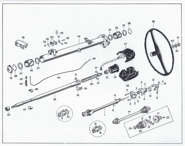
This is a diagram showing steering column components.

Steering Wheel Assembly

Steering Wheel Assembly

The disassembly procedure I followed is outlined below:

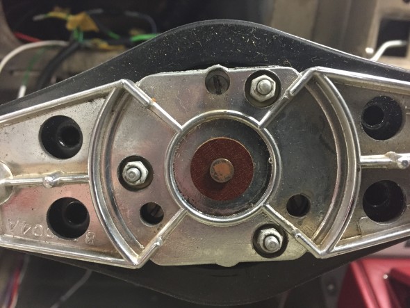
First I removed four slotted set screws from behind the steering wheel this enables the horn ring cover to be removed along with the horn push and return spring.

Horn Ring Assembly

Horn Ring Assembly

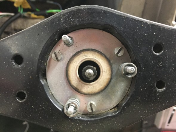
The horn ring assembly is held in place by three small nylock nuts (#6?) on studs. These nuts were removed and behind each nut was a nylon shouldered washer. The horn ring assembly is spring loaded so when the third nut is removed one needs to be careful not to lose the springs behind the assembly. After the three nuts and washers are loosened the horn ring can be lifted away.

Horn Assembly Springs on Studs

Horn Assembly Springs on Studs

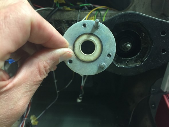
This reveals springs on two of the studs and a mounting plate held in place by three cheesehead machine screws. The springs were set aside and the three screws and slit washers were removed allowing the subsequent removal of the mounting plate with its three studs.

Horn Assembly Mounting Plate

Horn Assembly Mounting Plate

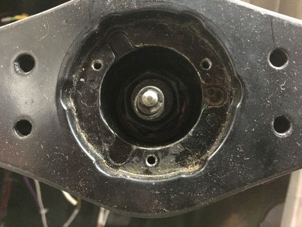
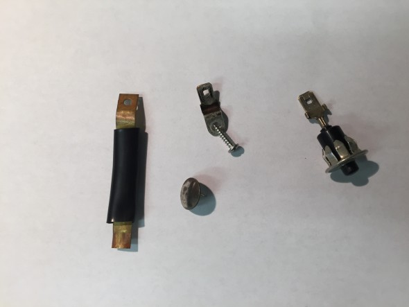
This revealed the horn button wire which contains the contact button, a spring, a small flat washer and a circlip holding the assembly together. a tubular black insulation piece is behind the wire assembly and slips into the shaft. It is NOT necessary to disassemble this horn contact wire in order to remove the steering wheel.

Horn Electrical Contact Wire, Retaining Clip, Washer and Spring

Horn Electrical Contact Wire, Retaining Clip, Washer and Spring

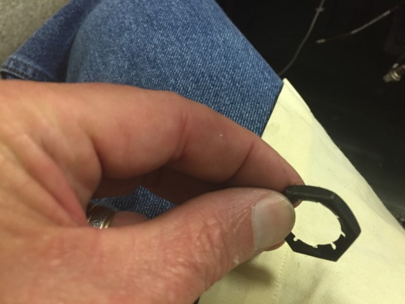
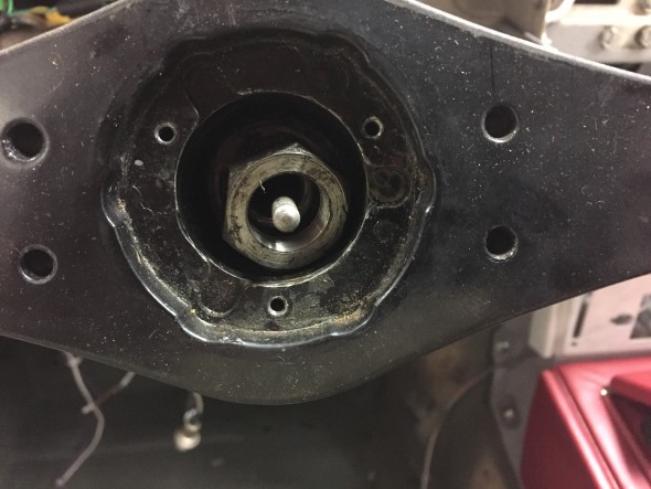
Also revealed was a locking Palnut on the steering shaft that was removed with a  15/16″ socket.

Steering Palnut on Shaft

Steering Palnut on Shaft

Steering Palnut Removed

Steering Palnut Removed

After removing the Palnut, the nut and special washer securing the steering wheel to the inner column shaft can be seen and removed. A 1  1/16″ socket was used.  The steering wheel could be then be removed from the shaft.

Steering Shaft Nut with Special flat washer

Steering Shaft Nut with Special flat washer

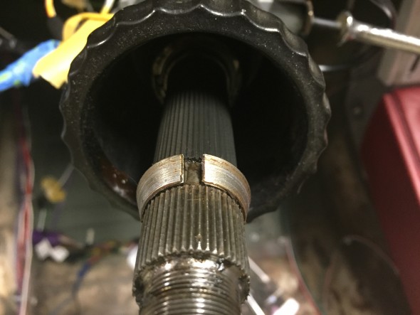
Steering Shaft Cone for Seating the steering wheel on the Shaft

Steering Shaft Cone for Seating the steering wheel on the Shaft

Care must be taken to not lose the two-piece split cone that seats the steering wheel on the shaft. These are revealed following removal of the steering wheel.

New Wiring Harness Circuits

Power Inputs to the Classic Technologies’ Relay/Fuse Panel

The Classic Technologies Panel has four primary connections.
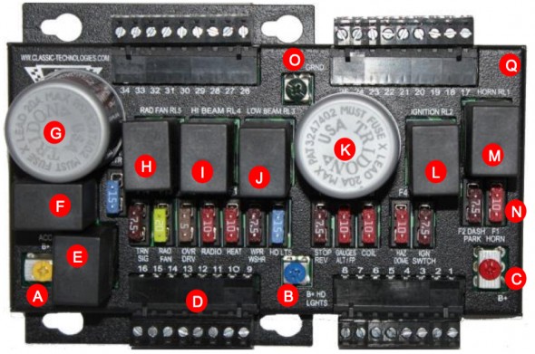
Classic Technology's Relay Fuse Panel

Classic Technologies’ Relay Fuse Panel

A – 12V power input from the small fuse box (battery B+) to power the accessories circuits. A brown 12 AWG wire is used to the Yellow screw terminal spade lug connection.

B – 12V power input from the small fuse box (battery B+) to power the high and low beam headlight relays. A brown/blue 14 AWG wire is used to the Blue screw terminal spade lug connection.

C – 12V power input from the small fuse box (battery B+) to power the constant power circuits in the vehicle. A brown 12 AWG wire is used to the Red screw terminal for a spade lug termination.

O – ground or earth to the car’s chassis.

In my case, 12V power is routed from the battery in the trunk to the starter solenoid mounted centrally on the firewall in the engine bay. The negative terminal of the battery is wired to the car’s chassis. A ground strap is used to connect the grounded chassis to the engine/gearbox.
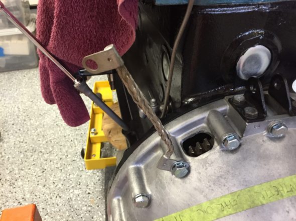
Ground Strap Mounted

Ground Strap Mounted

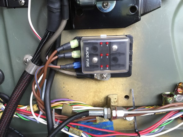
The battery relocation to the boot was addressed in a previous post.From the solenoid, a brown 8 AWG wire delivers power to a small fuse box with six circuits mounted on the firewall directly below the starter solenoid. I used two nutserts for the mounting to the firewall.  Three of the six fused circuits are then used to provide power to three input terminals on the Classic Technologies’ relay/fuse panel. The additional three are spares for the moment.
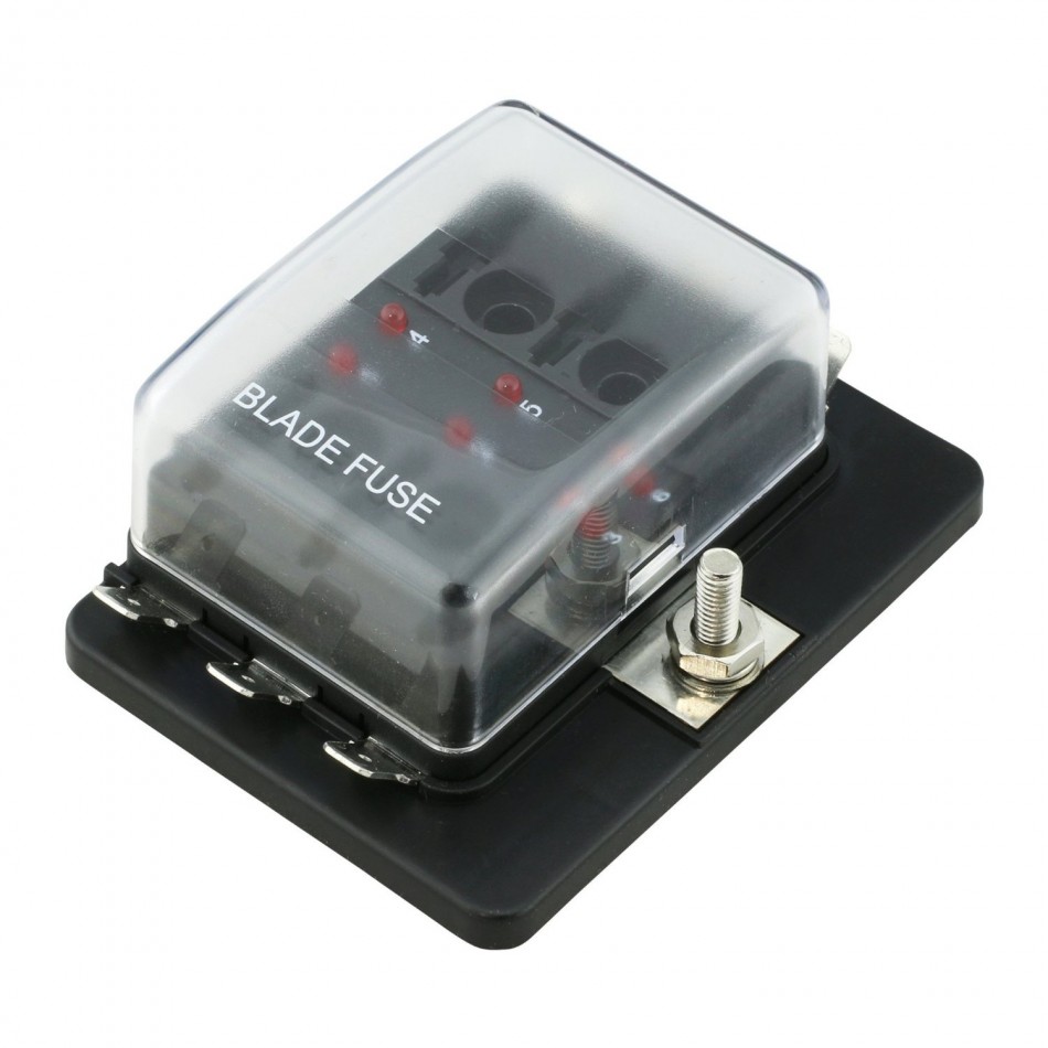
OnLine-LED-Store Six-Way Fuse Box

OnLine-LED-Store Six-Way Fuse Box

This is a diagram of the wiring to the Relay/Fuse Panel:
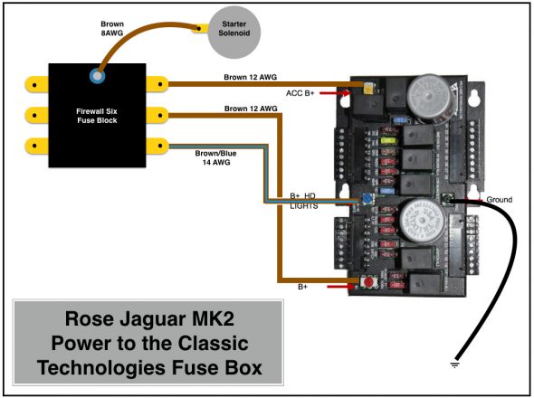
Rose Jaguar MK2 Power to the Classic Technologies Fuse Box
Rose Jaguar MK2 Power to the Classic Technologies Fuse Box

Six Way Firewall Fuse Box Delivering Power to Classic Tech Relay:Fuse Panel

Six Way Firewall Fuse Box Delivering Power to Classic Tech Relay:Fuse Panel

The three wires from the small firewall fuse box, the white/red wire from the solenoid to the fuse panel and the heavy 4 AWG cable from the solenoid to the alternator will be “packaged” together in one TechFlex sleeve/cover.

Before getting into the allocation of the thirty-four fuse positions available to use in the Classic Technologies Relay/Fuse panel, it might be helpful to once again point point out that as indicated in the post on new wiring harness connectors I developed a spreadsheet to be used in conjunction with wiring diagrams. The spreadsheet lists all connection points of the electrical wiring system. Links are provided below:

Again, a disclaimer is appropriate: The spreadsheet is provided as guidance for those who might wish to do something similar, but it should not be duplicated or utilized without careful inspection and  approval by a certified automotive electrician.

This alphabetical listing of components is provided to help quickly identify items in the electrical system. A spreadsheet line number(s) associated with the component is indicated.

Rose Jaguar MK2 Electrical Connections Alpha listing

This is the spreadsheet showing all connections:

Rose Jaguar MK2 Electrical Connections Spreadsheet

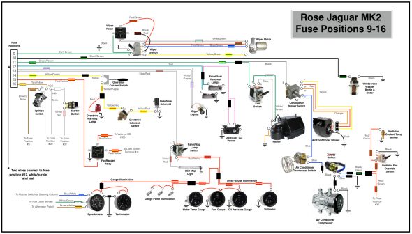
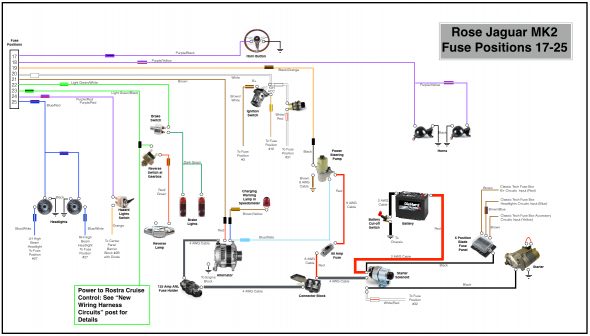
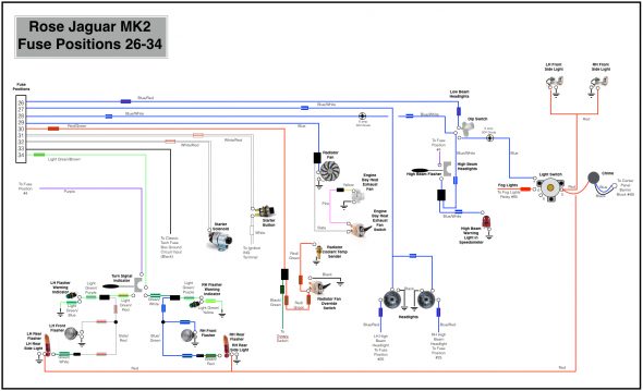
The following four diagrams illustrate the wiring sourced from the thirty-four fused positions in the system. Please let me know if as a reader you note an error or an omission. I apologize for the somewhat primitive diagrams as I did not have proper software available to do the job. I resorted to “Keynote” a presentation software to complete the task.
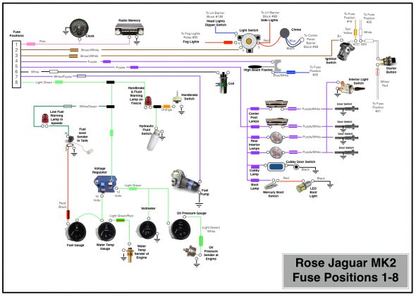
Rose Jaguar MK2 Fuse Positions 1-8
Rose Jaguar MK2 Fuse Positions 1-8

Rose Jaguar MK2 Fuse Positions 9-16
Rose Jaguar MK2 Fuse Positions 9-16

Rose Jaguar MK2 Fuse Positions 17-25
Rose Jaguar MK2 Fuse Positions 17-25

Rose Jaguar MK2 Fuse Positions 26-34

Rose Jaguar MK2 Fuse Positions 26-34


Circuit Modifications & Additions

Several of the modifications I am making to my MK2 require either modified or new electrical circuits. I highlight below the details of some of these wiring changes.

Starter Solenoid

I replaced the original starter solenoid with a new one sourced from SNG Barratt. The large post closest to the firewall provides the mounting for the 4 AWG cable to the starter. The large post closest to the engine mounts three cables: the 2AWG cable from the battery, the 4AWG cable to the block connector on the electrical panel on the LH engine bay valance (ultimately to the alternator), and a 8AWG wire to the 6-way firewall fuse panel. On the upper small post on the solenoid a single wire from the starter button is attached.

Alternator

I have considerably more power requirements in my car than could be addressed by the original dynamo/generator.

The specifics of the Hitachi 120 amp alternator I am using may be found under the “electrical components” posting. However, I will detail the wiring to support the alternator here.

I decided to go with 4AWG cable and also decided to install a fuse in the line between the alternator and the wiring system to avoid any possibility of a problem with a power surge created by a bad regulator in the alternator.

I sourced the cable and fuse from CE Auto Electric Supply. The folks at CE Auto Electric Supply are very helpful and they sell high quality products. Both products are typically used in high-end sound system applications. This particular cable has 1,862 strands. The cable was terminated with 3/8″ terminals, properly crimped and covered with adhesive shrink tubing.
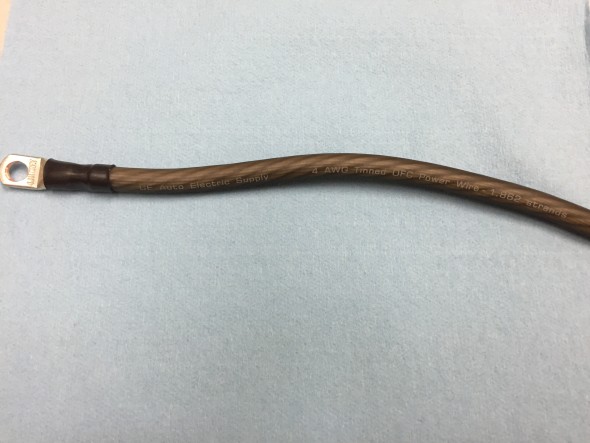
Alternator Cable CE Supply 4AWG 1862 Strands

Alternator Cable CE Supply 4AWG 1862 Strands

I installed a JL audio premium series master ANL fuse block with a 125 amp “Stinger” ANL style fuse, part number SPF52125 on the lower right portion of the original fuse panel.
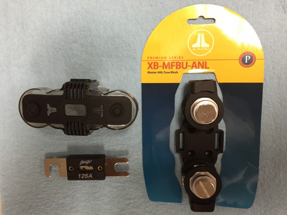
ANL 125 Amp Fuse with J&L Holder

ANL 125 Amp Fuse with J&L Holder

Two three-quarter inch long machine screws were used to secure the fuse block to the panel. On one I was able to take advantage of the 10–32 captured nut that was already on the fuse panel, and on the other I used a nutsert with the 10-24 screw.

One of the nice features of this particular fuse block is that the ProStar hexagonal posts can be rotated so that the cable can approach from almost any angle. As you can see in the photo, I took advantage of this feature. After the engine is installed, the alternator cable will be cut to proper length.

As can be seen in the image, the cable from the ANL fuse connects to a connector block also used for the power steering.
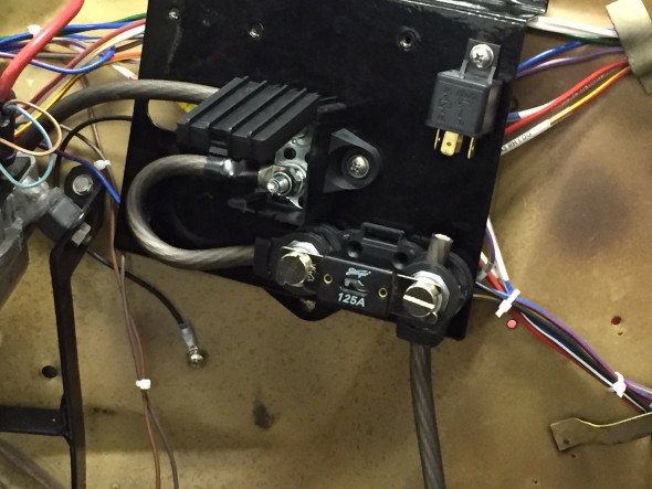
Alternator Fuse Mounted

Alternator Fuse Mounted

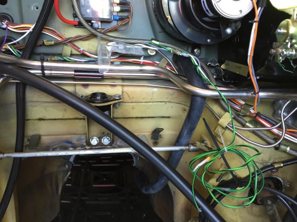
The cable is then routed from the connector block along the LH valance and the firewall to the starter solenoid. It is difficult to track because of all of the in-process wiring, but the path of the alternator cable is visible in the image below:
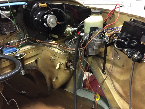
Alternator Cable Wiring

Alternator Cable Wiring

Power Steering Pump

The installation of the power-assisted rack and pinion steering requires the conversion to negative earth and the installation of an alternator replacing the original dynamo/generator. The kit, as supplied, provided a Lucas 80 amp LMA 604 alternator. However, due to other electrical requirements I chose to upgrade to a 120 amp Hitachi alternator. Details about the alternator are found at this link: https://valvechatter.com/?p=4113.

M&C Wilkinson provided wiring instructions, but my configuration is slightly different than in the application they referenced. The wiring diagram below is my interpretation of the wiring required for the pump in my car.

Five wires emanate from the pump. The heavy brown wire connects to ground. The heavy red cable connects to the supplied 80 amp fuse. The 22 gauge black wire connects to the fuse panel at location #19 or #23. The 22 gauge blue/slate wire connects to the alternator at the indicator lamp post.
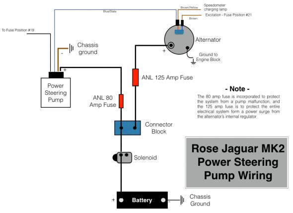
Rose Jaguar MK2 Wiring Diagram for Electric Power Steering Pump

Rose Jaguar MK2 Wiring Diagram for Electric Power Steering Pump

In this image I have installed the 80 amp fuse for the power steering pump. The Bosch relay will be used for the Fogranger fog lamps. All of this will be out of view once the black sheet metal cover his made for the panel.
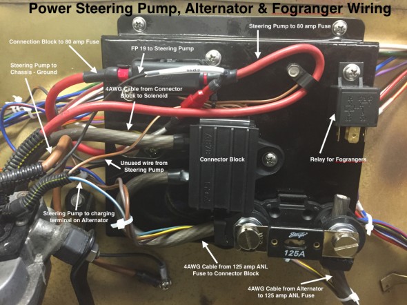
Power Steering Pump, Alternator & Fogranger Wiring on Electrical Panel

Power Steering Pump, Alternator & Fogranger Wiring on Electrical Panel

Heater Fan Wiring

A full description of the restoration and modification of the heater box and fan may be found at the Heater Post on this Valvechatter website. The following information addresses the wiring of the heater fan.

The orange wire from the motor is connected to ground. The black wire to the “inside” post (closest to the heater box) of the resistor. The slate wire from terminal #6 on the switch is connected to the “outside” post (closest to the blower fan) of the resistor. The white/green wire from terminal #8 on the switch connects to the “inside” post on the resistor. The green/yellow wire from the #4 terminal of the switch is connected to the fuse position #11 for power. With this wiring in place, the lower position of the switch is “off,” the middle position is “Low Speed” and the upper position is “High Speed.”

I created a pigtail (seen below) from the resistor for the heater fan wiring. Two wires in the pigtail are connected through two-way snap connectors to wires of the same color which route through the firewall and ultimately back to the Fan Switch. The black wire in the pigtail goes directly to the fan motor. The orange wire from the motor is the ground and it is connected to the LH valance grounding terminal strip.
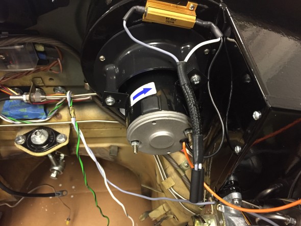
Heater Fan Wiring

Heater Fan Wiring

Heater Fan Wiring

Heater Fan Wiring

Wiper Motor Wiring

As documented in my post entitled Wiper System Upgrade, I installed a Lucas 29W wiper motor kit from Classic Motor Cars in the UK. The upgrade includes a relay mounted behind the central instrument panel assembly. The wiring for the wiper switch is referenced above under the section “Instrument Panel Assembly Switch Wiring.” This is a diagram of the wiring:
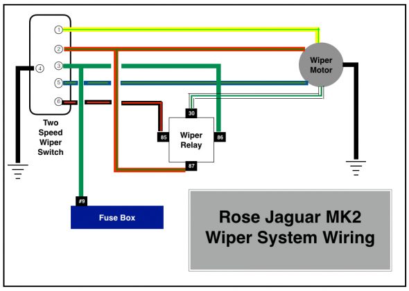
Rose Jaguar MK2 Wiper System Wiring

Rose Jaguar MK2 Wiper System Wiring

This is an image of the wiper motor mounting. I used eight of the ten connection points in a ten-way rubber snap connector and fastened it to engine bay RH valance with an original type retaining clasp. note the wiper motor ground connection to the upper left.
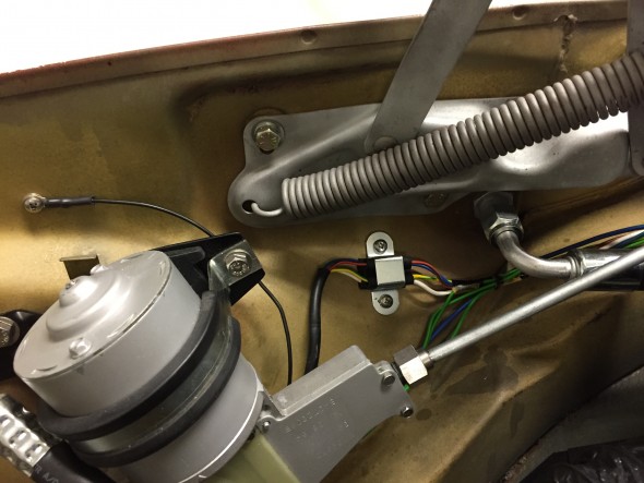
Wiper Motor Mount and Wiring

Wiper Motor Mount and Wiring

Cruise Control Wiringcruise-control-installation-disclaimer-001

A full description of the installation of the Rostra Cruise Control System in my MK2 is provided in the MK2 Cruise Control Post. My wiring diagram, tailored for my 1964 Jaguar MK2 application, is provided below. As the disclaimer above indicates, the wiring description in this post journals what I did for my car. It is not my intention to describe what you should do for your car!

This is a link to a pdf of the wiring diagram and it is also shown in the image below:

rostra-cruise-control-wiring-for-jag-mk2
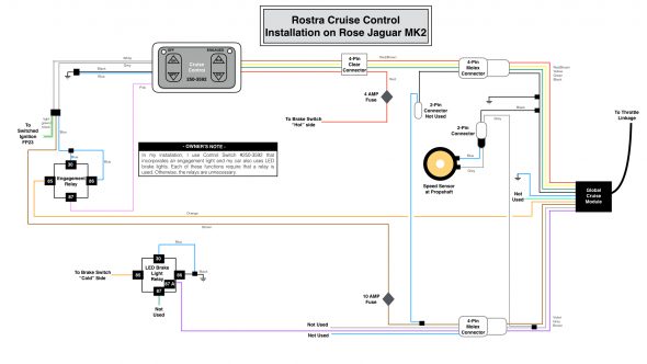
Rostar Cruise Control Wiring for the Rose MK2

Rostar Cruise Control Wiring for the Rose MK2

Central Locking and Keyless Entry Wiring

A full description of the locking system may be found at the “Remote Control Door Locks web site entry: https://valvechatter.com/?p=9205. The wiring for the system is comprised of two components. The MES Central Locking Control Module operates the door lock actuators. Once that system in properly installed and operating as it should, the AVITAL keyless entry module is added to permit use of a key fob to wirelessly lock and unlock all doors. An added feature of the system is that about fifteen seconds after ignition all doors are locked automatically. 

The following wiring diagram is unfortunately a bit busy. This is a link to a pdf file of the diagram: Keyless Entry Power Locks for Rose Jag MK2 and a jpeg file is depicted below:
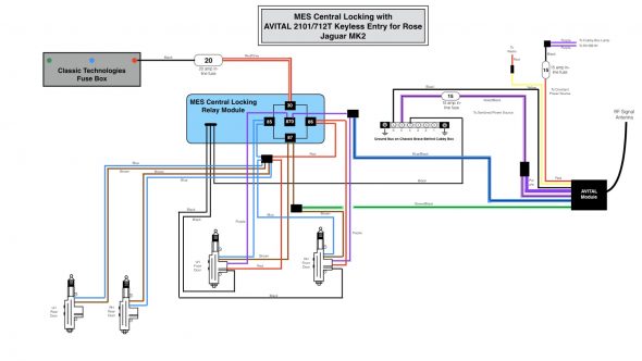
Keyless Entry Power Locks for Rose Jag MK2


Air Conditioner Operating Controls Wiring

A full description of the installation of the RetroAir air conditioning system in my MK2 is provided in the “Air Conditioning” Post. The wiring of the controls and devices for the air conditioning system is depicted in the following diagram:
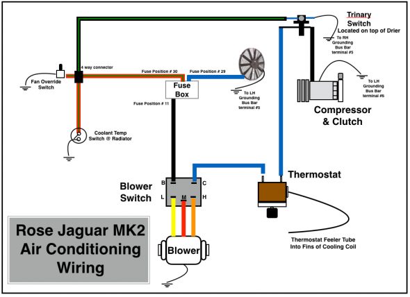
Rose Jaguar MK2 Air Conditioning Wiring

Rose Jaguar MK2 Air Conditioning Wiring

This is a photograph of the wiring harness provided in the RetroAir kit. In my application I did not use the circuit breaker shown in the image because I wired the blower switch directly to the fuse panel and protected the system at that point with a 40 amp fuse.
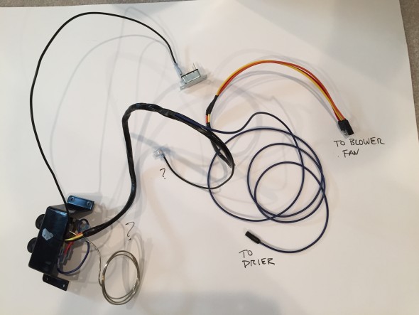
RetroAir Wiring Harness Kit

RetroAir Wiring Harness Kit

As the diagram above illustrates, I chose to install a trinary pressure safety switch in the air conditioning electrical circuit. The trinity switch is also discussed in the “Air Conditioning Post.”
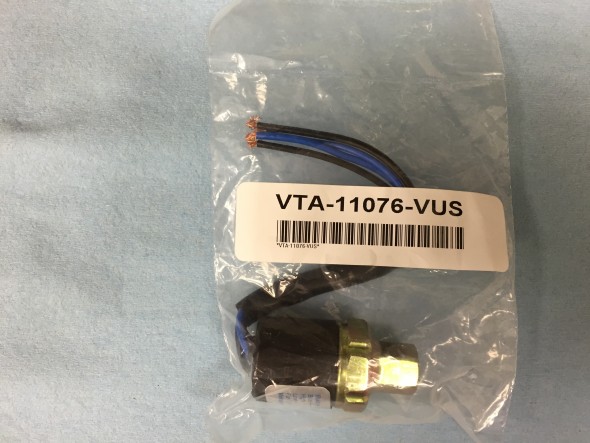
Vintage Air Trinary Switch

Vintage Air Trinary Switch

The Vintage Air trinary switch kits combine low and high pressure compressor clutch cut-off functions plus an electric fan engagement signal at 254 psi. The low pressure cut-off of these trinary switches is 30 psi and the high pressure cut-off is 406 psi.

http://www.vintageair.com/Instructions2013/904678.pdf

The switch as supplied has two blue wires and two black wires. Because the switch is located in a right from wheel well and exposed to the elements, I connected the four wires to a waterproof connector purchased from British Wiring, and then routed the wires to their termination points. One blue wire is for ground and the other for fused power. One black wire connects to the compressor and the other to the thermostat controller for the air conditioner.

Turn Indicator and Headlamp Flasher Switch at the Steering Column  and the Laycock De Normanville Overdrive Switch and Wiring

The electric overdrive is activated by a lever switch on the right side of the steering column. Power is derived from fuse position #14 of the CT fuse box. With lever activation a signal is sent to the overdrive interlock, or top gear switch located on the top of the gearbox and then to the overdrive solenoid. A warning indicator bulb is illuminated when the overdrive is engaged. More information about the switch and lever mechanism may be found in the “electrical components” post.
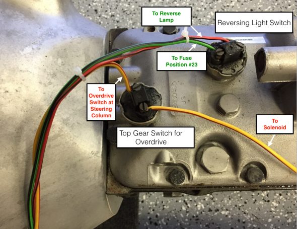
Overdrive Interlock or Top Gear Switch at gearbox

Overdrive Interlock or Top Gear Switch at gearbox

The lever on the left side of the steering column is used in an upward and downward motion to activate the LH and RH turn indicator flashers at the front and rear of the vehicle. When the flashers are functioning an indicator bulb located in a centralized position behind the steering wheel is illuminated in a flashing pattern. The headlamp flasher is activated by the driver pulling the same lever toward himself. This action will trigger the high beam warning light in the speedometer.
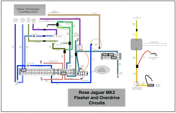
Rose Jaguar MK2 Flasher Circuit & Overdrive
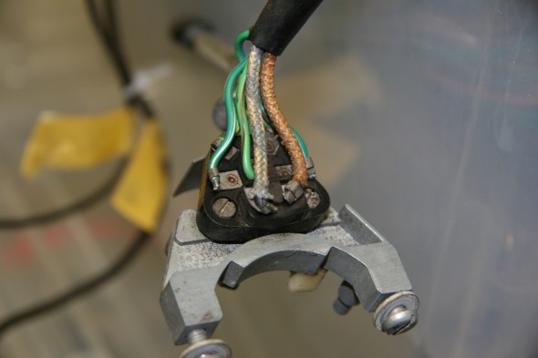
Rose Jaguar MK2 Flasher Circuit & Overdrive

Turn Signal Switch Wiring
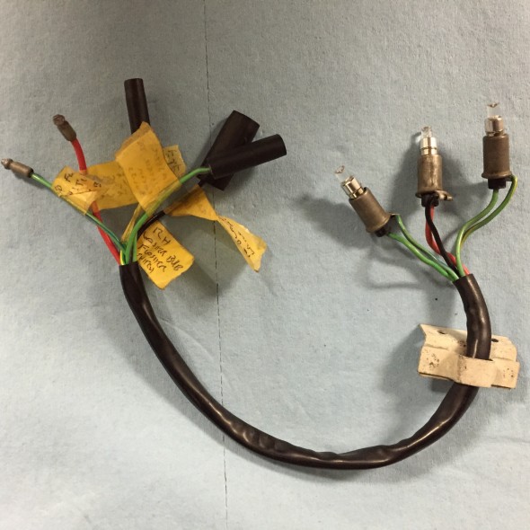
Turn Signal Switch Wiring

Turn Signal and overdrive indicator bulbs, holders, and pigtail

Turn Signal and overdrive indicator bulbs, holders, and pigtail

Auxiliary Power/USB Ports

I intend to install an arm rest/console between the front seats in my MK2. The console will include an auxiliary power/USB port unit. Power is sourced from the fuse box, position #12.
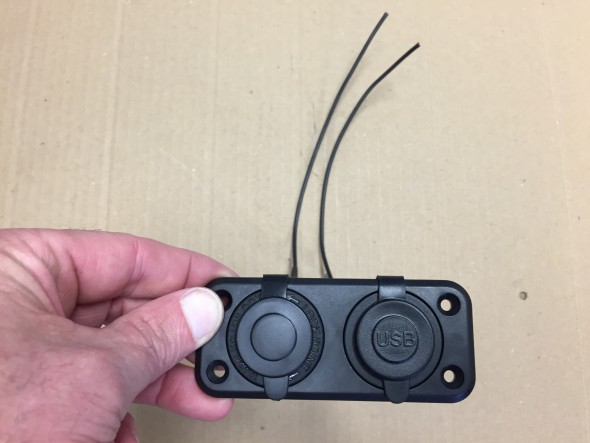
Auxiliary Power and USB unit
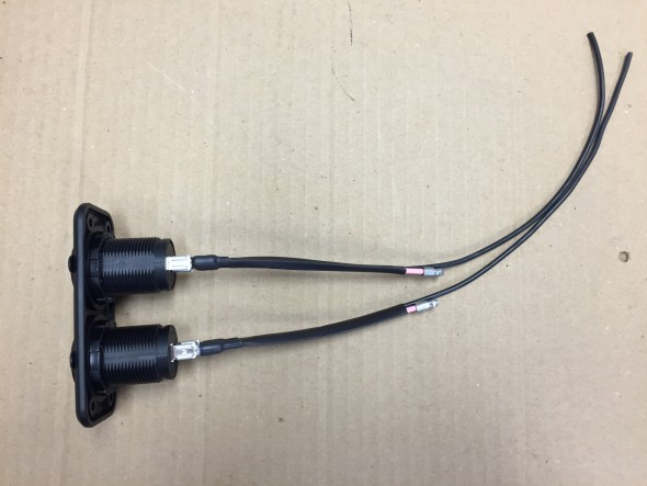
Auxiliary Power and USB unit

Auxiliary Power and USB unit

Auxiliary Power and USB unit

Powered Front Seats

The front seats I am using are from a Jaguar XJ40. More information about the seats is available at the “Seating” post. They have more features than I plan to use.
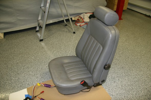
1990 Daimler Front Seats

1990 Daimler Front Seats

Although the wiring harnesses were complete, there were a number of electrical connectors on the harnesses with no explanation as to what needed to be connected where to get the seats functioning.
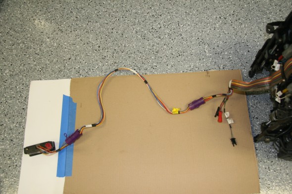
Seat Wiring Harness and Switches

Seat Wiring Harness and Switches

The seats have seat heaters (upper and lower cushions), a memory feature for the driver’s seat, seat belt alarms, and wiring to permit automatic movement of the driver’s seat to the aft position when the driver’s door is opened.

After some enquiries on the Forums, Bryan Neish came to my aid. He was of great help figuring out what the wiring at each of the connectors did. I know he spent quite a lot of time reviewing wiring diagrams to find what I needed. George Leicht was also helpful. He sent along the wiring diagram that accurately reflected my seat wiring.

I wired the seats to unswitched power at the fuse box to facilitate seat operation before entry or before starting the ignition. I was able to use the original seat wiring harness and bank of switches to control the four motors adjusting the lower and upper seat cushions for each chair. The wiring runs under the center console to each seat. A pdf file of the seat wiring schematic for 1990 may be found here: 1990 Jaguar XJ40 Seat Electrical Schematic

I have yet to decide where I will mount the switches. The image below shows the approximate location of the switches as Ton Tulleken installed them on his car:
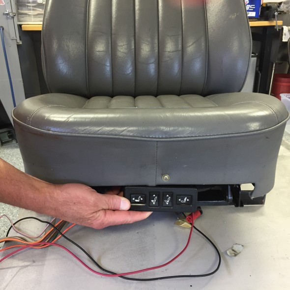
Possible Placement of Seat Switches
Possible Placement of Seat Switches

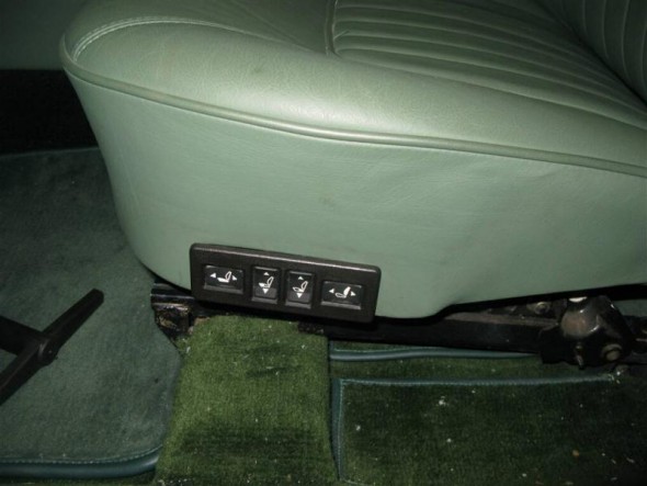
Kevin Moore's MK2 power seat switches

Kevin Moore’s MK2 power seat switches

The image above shows the location of the switches in Kevin Moore’s car.

Lighting

SideLights

Additional detail about the sidelamps may be seen in the exterior lighting post. I rewired the original side lamp fixtures and trial fitted them to the body. The rubber “O” rings supplied by SNG Barratt are to thick to fit properly so I replaced them with metric 24mm – 2mm “O”rings ordered from McMaster Carr. New LED bulbs were also fitted in the fixtures. The red 18 AWG wire from the bulb is combined with a black 14 AWG ground wire from the fixture in a vinyl sleeve that goes through the LH and RH valance lighting grommet.
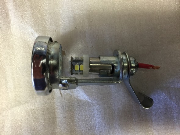
SideLamps
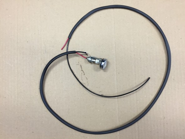
SideLamps

RH Side Lamp Wiring & Sleeving
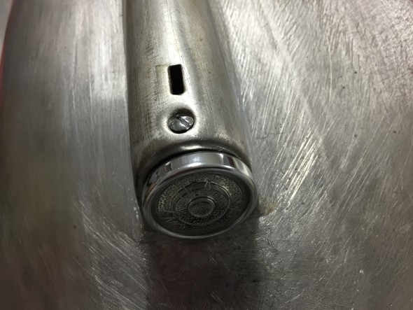
RH Side Lamp Wiring & Sleeving

Refurbished side lights installed

Refurbished side lights installed

Turn Signal Flasher Lamps

After installing the side lamps I moved to the turn signal flashers. Information about the lamps is contained in the exterior lights post. I re-used the original fixture wire terminals but replaced the power and ground wiring with new. The power wire is blue/green 18 AWG and the ground wire is black 14AWG. The wiring is pushed through holes on the back end of the fixture’s new rubber boot. New vinyl sleeving was also used for the flasher lamps.
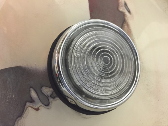
Front Flasher Turn signal
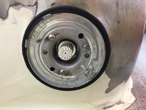
Front Flasher Turn signal

Turn Signal Flasher with LED Installed
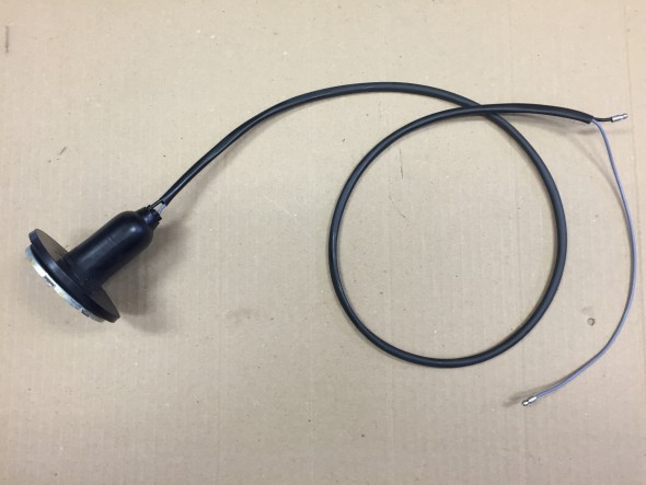
Turn Signal Flasher with LED Installed

Turn Signal Flasher Wiring

Turn Signal Flasher Wiring

Fograngers

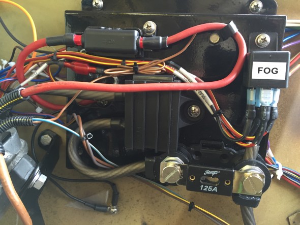
More information about the fog rangers may be found in the exterior lights post. The Classic Technologies Fuse box did not have a relay designed into the product for fog or driving lights, so I added a Bosch relay for this function. It is mounted on the original fuse panel in the engine bay on the LH valance. The foglights are controlled by the primary light switch.
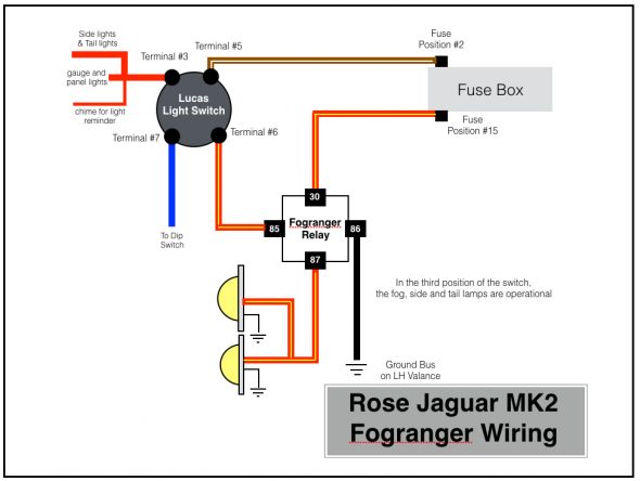
Rose Jaguar MK2 Fogranger Wiring
Rose Jaguar MK2 Fogranger Wiring

Fogranger Relay
Fogranger Relay

RH Fogranger Installed

RH Fogranger Installed

Headlights

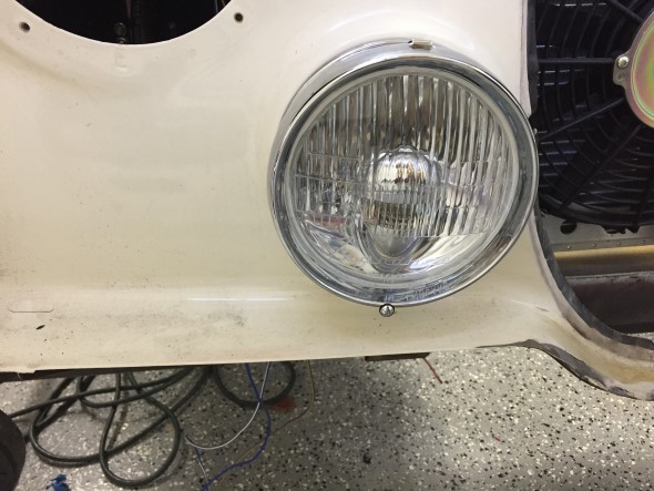
More information about the headlights may be found in the exterior lights post. I installed new 3 wire (high beam, low beam, and ground) plugs, wiring and sleeving for the headlights.
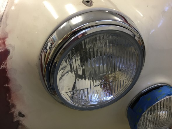
Headlight Installed with Newly Chromed Trim Ring

Headlight Installed with Newly Chromed Trim Ring

Although not too pretty yet, this image shows the temporary installation of all of the front exterior lights. The blue painter’s tape is to protect the chrome. The installation was done to make sure that I had all the parts needed for a particular light and to test the electric circuitry and switches.
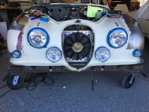
Temporary Installation of front Exterior Lights

Temporary Installation of front Exterior Lights

These images show the exterior lights wiring in new sleeving as it is routed from the individual fixture through the large wiring grommet located on each valance.
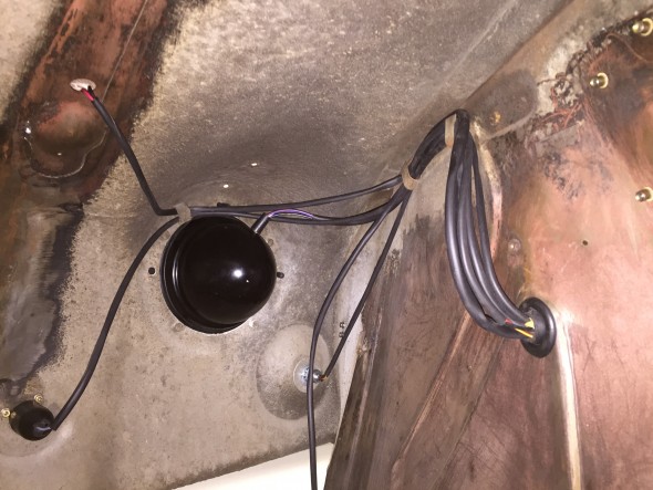
LH Front Exterior Lights Wire Sleeving and Routing
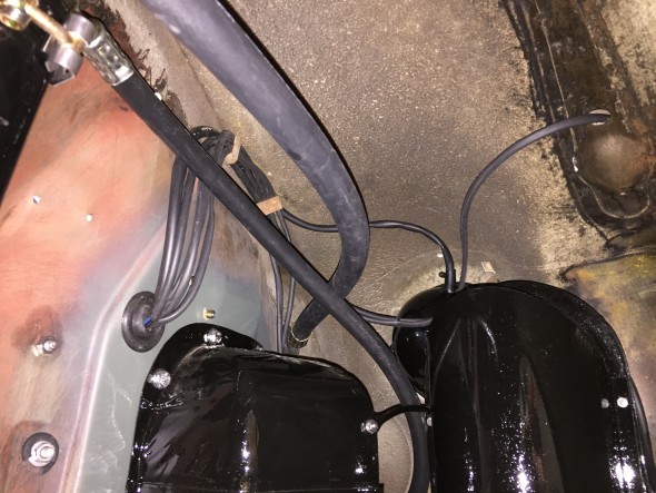
LH Front Exterior Lights Wire Sleeving and Routing

RH Front Exterior Lights Wire Sleeving and Routing

Tail Lights

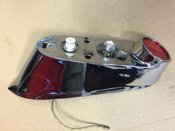
More information about the tail lights may be found in the exterior lights post. I substituted LED bulbs for the original incandescent type; however, the wiring remains the same. In fact, I was able to reuse the original wire leads from each of the bulb holders. The upper bulb is for the flasher with a single wire lead. The lower bulb is for the regular lights plus an additional light for the brakes with a double wire lead.
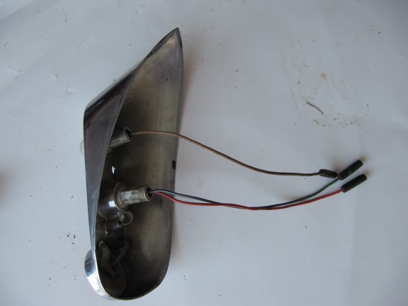
Tail Light Wire Leads
Tail Light Wire Leads

Tail Light LED Bulbs

Tail Light LED Bulbs

Number plate illumination and reverse lamp

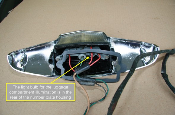
More information about the lamp may be found in the exterior lights post. The lamp includes one light for the luggage compartment, two bulbs for the license plate illumination, and one bulb for reversing. All original incandescent bulbs were replaced with LEDs. The original wiring harness for the lamp was in pretty good shape, but I constructed a new one with all fresh wiring.
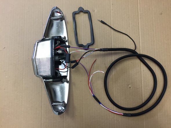
Boot Lamp with new wiring harness

Boot Lamp with new wiring harness

Luggage compartment lamp

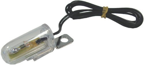
As my friend Eric Kriss points out in his MK2 restoration blog, the luggage lamp seemed to be an afterthought to Jaguar engineers. To function the light switch on the gauge panel had to be turned on, but it is often the case that one would want to access the luggage area after the car’s ignition, much less its lights were turned off! Instead of wiring the luggage compartment lamp in series with the front marker and rear tail lights, Eric revised the wiring to move the luggage compartment lamp to its own circuit. To make the lamp illuminate when the boot lid is opened a position sensitive mercury tilt switch is used. As Eric describes, when upright a ground connection is established permitting current to flow to the bulb. When the boot lid is shut, the ground connection is broken so the light goes off.Mercury Tilt Switch
 

Interior Lights

The MK2 as original had six interior lamps: the map light at the central gauge panel, a lamp at the top of each center or “B/C” pillar, a lamp in the cubby box and a lamp on each side of the rear of the car above the passenger seat. These latter lamps referred to as rear quarter interior lamps. My Mk2 will also have two courtesy lamps in the back of the front seat headrests. More information concerning these lamps may be found at the “Interior Lights” post.

As pointed out in the “Interior Lights” post, the replacement center pillar lamps are not exact replacements for the originals. They are operationally superior in that they provide an “on-off” switch at the lamp, and also because they screw, rather than snap, together. They just don’t look quite as nice being plastic rather than chrome metal. Just to check fit and to test the electrical system I did install the new center pillar lamps mounted on their wood bases. An additional grounding wire is used with the new lamp for its switch so there are three wires rather than the original two. For purposes of testing the electric system I temporarily fixed the third ground wire to the pillar as shown in the third photo below.

36 mm festoon bulbs in warm white were substituted for the original incandescent bulbs.The lamps are wired to the interior lighting circuit that includes the interior lamps toggle switch on the central gauge panel as well as the four door switches. The black ground wire is simply attached to the metal center pillar.
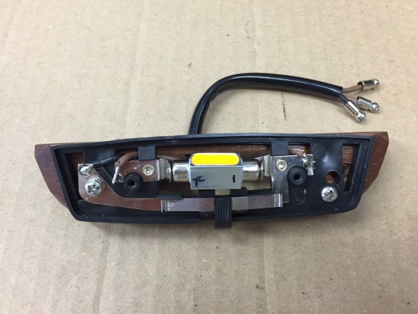
New three-wire center pillar lamp with switch
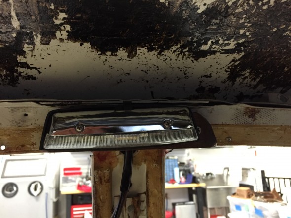
New three-wire center pillar lamp with switch

New center pillar lamp loosely mounted on wood base
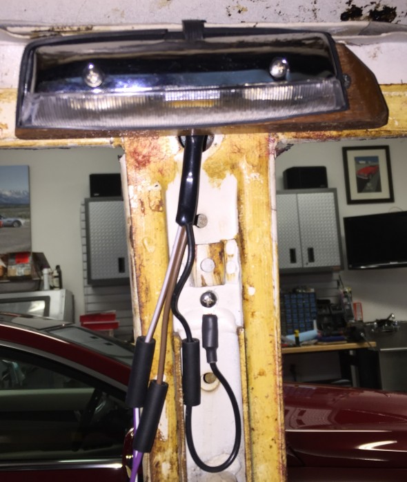
New center pillar lamp loosely mounted on wood base

Temporary ground connection for center pillar lamp switch

Temporary ground connection for center pillar lamp switch

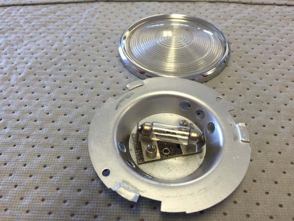
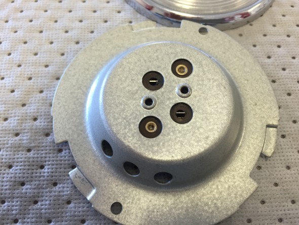
I trial fit the new, but as original, rear quarter lamps which required making new plywood mounting frames. Wiring for the rear quarter interior lamps initiates at fuse box to the interior lamp switch on the gauge panel and then proceeds through the LH and RH sills to the lamps. There is also a switch in each door that activates the interior lamps should any of the four doors be opened. I did not use wiring pigtails for these lamps. 36 mm festoon bulbs in warm white were substituted for the original incandescent bulbs.
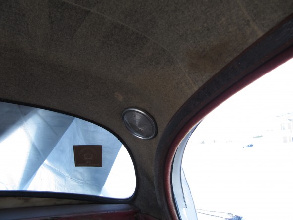
Rear Quarter Interior Lamp
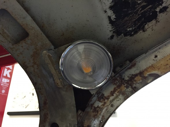
Rear Quarter Interior Lamp

LH rear quarter interior lamp

LH rear quarter interior lamp

I am using XJ40 powered seats in my MK2. The seat headrest lights were originally wired in such a way that they too illuminated when the car’s doors were opened. These lights also have an integral on/off rotary or dial switch. Without the central processor of a more modern car it would be all too easy to leave these lights on and eventually drain the battery. Therefore, I elected to wire these lamps to a switched power source rather than a constant power source like the other lamps. I did not use the terminal on the headrest light that would normally have a red/green wire to the door switches.
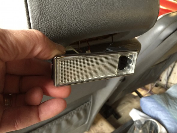
XJ40 Hedrest Lamp Installation
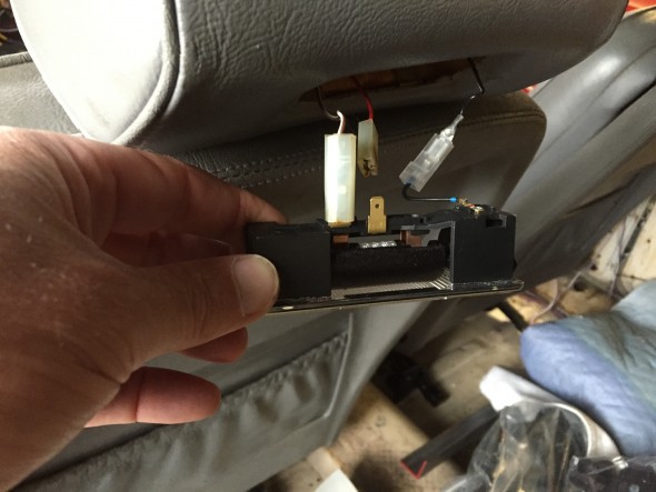
XJ40 Hedrest Lamp Installation

XJ40 Headrest Lamp Wiring

I was able to use the original door switches in my rebuild. I just rewired each of them with new wire.
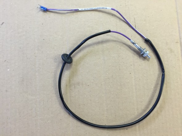
Front Door Interior Light Switch and Wiring

Front Door Interior Light Switch and Wiring

The front door switch is mounted in the lower door hinge and travels through the kick panel to the switch.
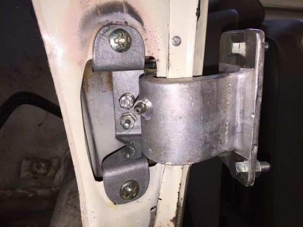
Front Door Interior Light Switch in Lower Door hinge
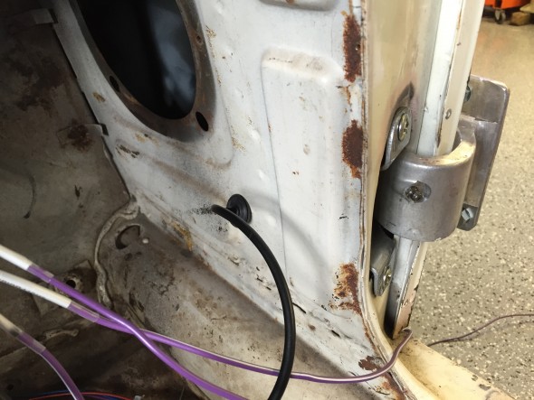
Front Door Interior Light Switch in Lower Door hinge

Front Door Interior Light Switch Wiring through Lower Kick Panel

Front Door Interior Light Switch Wiring through Lower Kick Panel

The rear door switch is mounted in the rear side of the B/C post or center pillar. The wiring for the switch travels from under the front dash, through the sill and up the center pillar.
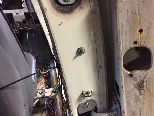
Rear Door Interior Light Switch in Center Pillar

Rear Door Interior Light Switch in Center Pillar

The Cubby Box lamp assembly wiring for Lamp/Switch consists of a metal base fixture, bulb, blue plastic cover and a switch controlled by opening the Cubby Box door. More images and information regarding the lamp may be found at the “Interior Lights” post. As with the other interior lamps, the original incandescent bulb was replaced with a 36 mm festoon bulb in warm white. Terminals on the back side of the metal lamp base connect to the fused power source and to the Cubby Box door switch. The image below illustrates the wiring sources and terminations for the Cubby Box.
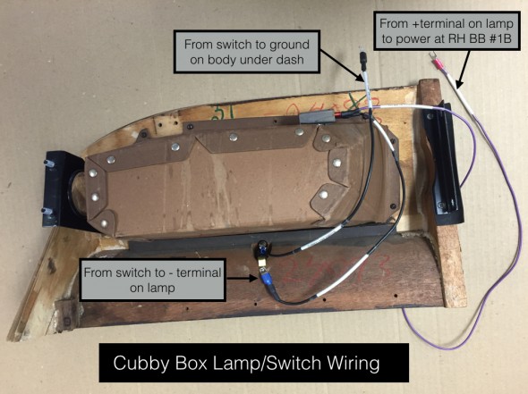
Cubby Box Wiring for Lamp:Switch

Cubby Box Wiring for Lamp/Switch

Some Details on a Few Other Assemblies

The LH and RH Fascia Board Assemblies were installed in the car so as to test the wiring for the speedometer and its warning lights, the tachometer with the internal clock, the “Handbrake “ON” position and brake fluid container level” warning lamp, and the “Cubby” glove box lamp. More information on these fascia boards may be found at the “Dash” post. All gauge/instrument illumination incandescent bulbs were replaced with LEDs.

I first connected the left turn signal flashing indicator, the right turn signal flashing indicator, and the overdrive engagement indicator from the indicators wiring pigtail to the direction indicator/headlamp flasher switch. A ground wire for the indicators was mounted to the body below the dash.
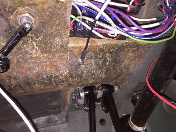
Ground connection under dash for indicator lights
Ground connection under dash for indicator lights

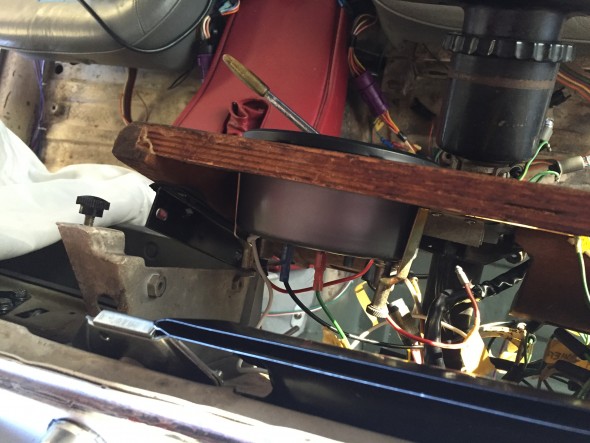
Loose fitting of fascia board for tach install

Loose fitting of fascia board for tach install

I found it easiest to loosely position the driver’s side fascia board and I then installed the tachometer with its two mounting clamps, a ground wire, the 12 volt power wire, the wire connecting the tach to the coil and the two instrument lights. Leaving the speedometer position open facilitates accessing the LH fascia board outside mounting studs/nuts.
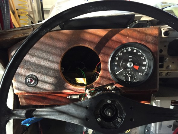
LH fascia board temporary install with tach in place

LH fascia board temporary install with tach in place

I then secured the LH fascia board to its mounts, followed by connecting the wiring for the handbrake/brake fluid level warning lamp.

I then connected the two speedometer illumination lights, the lights for the headlamp, ignition, and fuel warning lights, and the speedometer drive cable.

Installing the passenger side (RH) fascia board is much the same as the driver’s (LH) side. A sliding panel in the cubby box may be removed to provide access to the studs/nuts of the outside mounting bracket. The wiring for the “Cubby” lamp as shown in the write-up and image above is connected to ground and power.

Fuel Sender

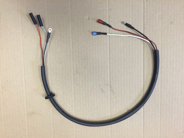
The fuel sender has its own short wiring harness consisting of three wires in a protective sleeving. One wire for ground, one for the fuel gauge (the “T” terminal on the sender for 10 volts) and one for the fuel level warning lamp in the speedometer (the “W” terminal on the sender). The embossed terminal markings are evident on the image below. My sender has an “E” marking for earth, although my grounding wire was fixed to one of the screws used to mount the sender to the tank. While the original harness was in good shape, I made a new one for installation in the Jag when the fuel tank is fitted.
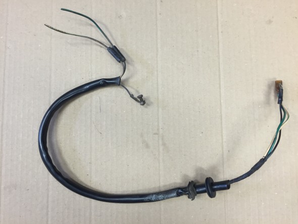
Original Fuel Sender Wiring Harness
Original Fuel Sender Wiring Harness

New Fuel Sender Wiring Harness
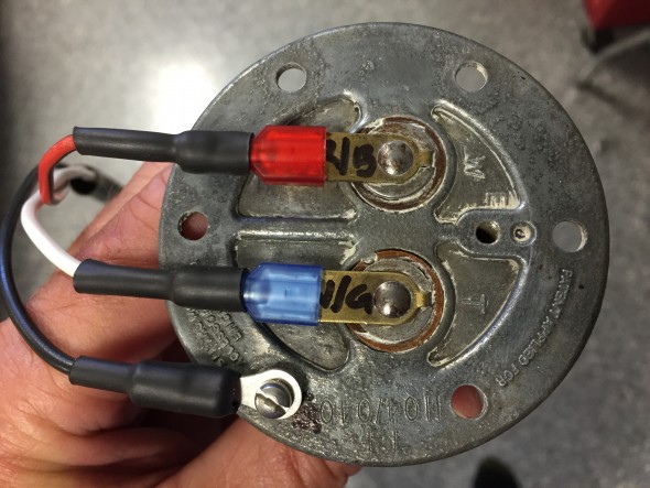
New Fuel Sender Wiring Harness

Fuel Sender Terminals

Fuel Sender Terminals

Warning Light for Handbrake and Fluid Level
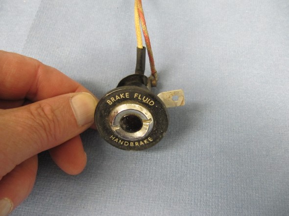
Handbrake and Fluid Warning lamp Escutcheon

Handbrake and Fluid Warning lamp Escutcheon

The lamp is activated by a switch at the base of the handbrake, mounted to a bracket located on the interior floor. See: https://valvechatter.com/?p=3913 under the handbrake post, or by a level indicator switch in the brake fluid reservoir is shown earlier in this post.
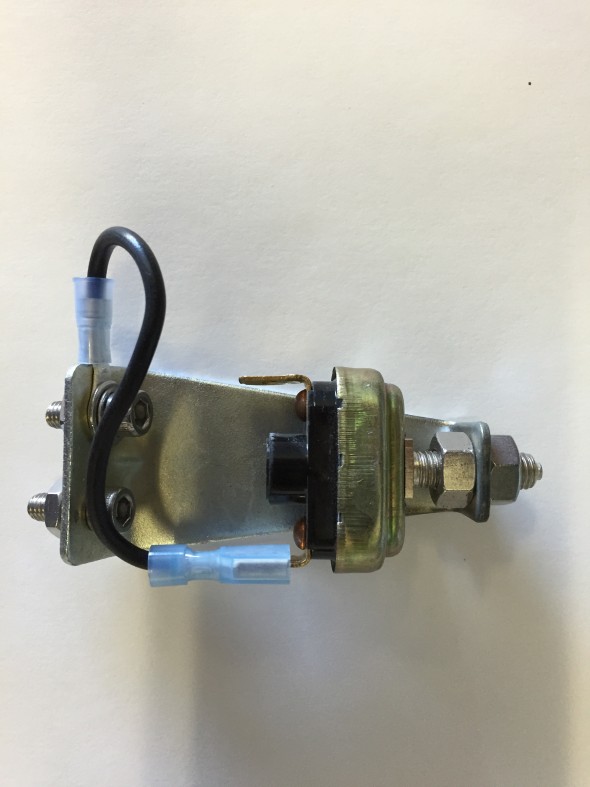
Handbrake Warning Switch

Handbrake Warning Switch

The “Warning Lamp Indicating Handbrake ‘ON’ Position and Level in Brake Fluid Container” is comprised of the cover and window assembly, a spring washer on the central terminal post, with nuts and washers. Rubber sleeves are slipped over the white wire at the terminal and the white and red/green wires are contained together in a rubber sleeve of about 4.” The warning light was cleaned and reassembled and a new face plate was installed.
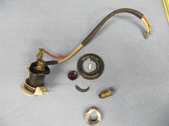
Warning Lamp

Warning Lamp

Hydraulic Fluid Reservoir, Low Fluid Warning Switch

The fluid canister contains a float activated level indicator switch in its screw cap.
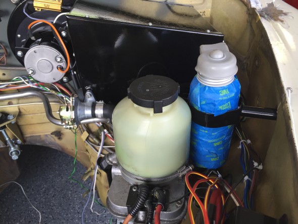
Hydraulic Fluid Container Location

Hydraulic Fluid Container Location

Two wires attach the switch with spade connectors and are protected by a rubber cap over the indicator plunger. I sourced a new canister and indicator switch (cap) from SNG Barratt. The canister is covered in blue painter’s tape just to keep it clean during the restoration build. I was able to reuse the original rubber protective cap. An 18AWG light green wire is connected to one terminal. This wire joins via a 4 way snap connector with an orange 18 AWG wire from the handbrake switch. A single orange 18 AWG wire then connects to the LH Barrier Block Terminal #5B. A dark green wire from LH Barrier Block #5A connects to a 2 way snap connector with a red/green wire on the dash warning light pigtail.

A black 14 AWG wire connects to the other level indicator switch terminal and provides a ground connection to the chassis.
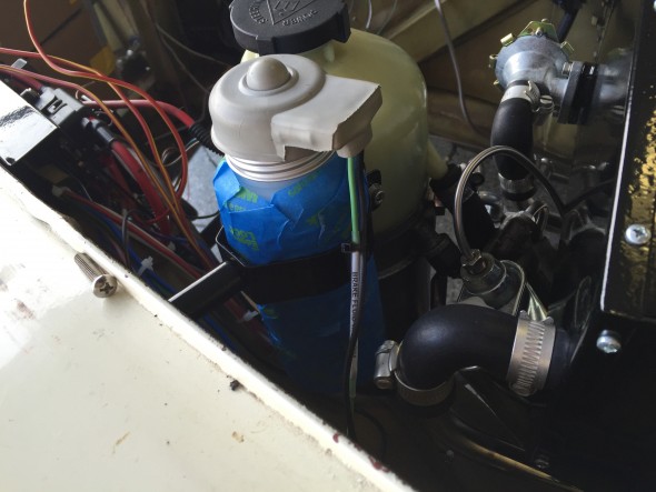
Hydraulic Fluid Container Wiring

Hydraulic Fluid Container Wiring
Interior

Rear View Mirror

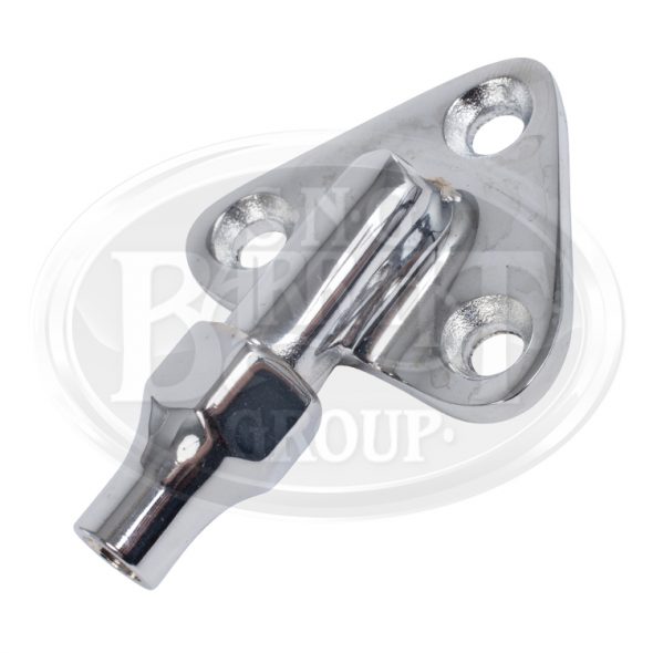
The parts manual does not provide much information on the rear view mirror. The assembly apparently came from Lucas and was installed as an assembly. Perhaps there is Lucas documentation available someplace, but I did not find it. My original mirror was pretty dirty and the height adjustment post would not tighten properly. A new mirror assembly is available from SNG Barratt, but I decided to use my original. I did purchase a new “Interior Mirror Mounting Clamp/Boss – C20697/1”, that addressed my sliding adjustment problem:

Mirror Mounting Clamp/Boss

Mirror Mounting Clamp/Boss

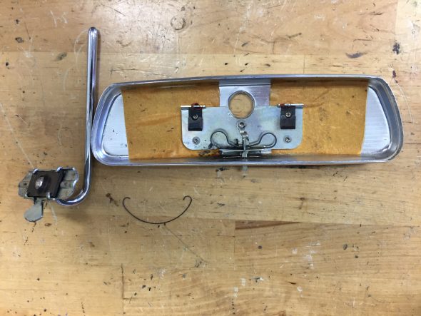
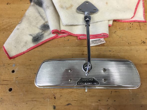
I also had my original mirror re-silvered by Tim Inman at Inman Historic Interiors www.historicinteriors.com/Resilvering.html The resilvering costs about $65 including shipping. The finished product looked like new. Reassembly is pretty easy but it does require carefully bending four tabs that secure the tensioning spring for the mirror ball joint. The image below shows the mirror casing and the spring assembly with adjustable post.

Rearview Mirror Before Assembly

Rearview Mirror Before Assembly

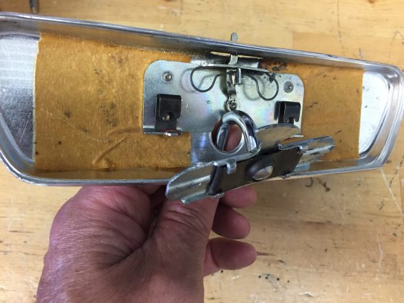
The image below show the installation of the post and tensioner spring with mounting plate:

Installing Rearview Mirror Components

Installing Rearview Mirror Components

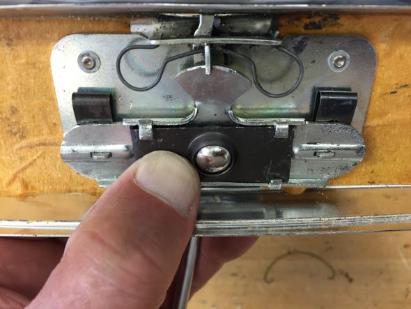
The image below shows the tensioner spring plate tabs bent back to secure the spring plate:

Tensioner Spring Tabs bent into Position

Tensioner Spring Tabs bent into Position

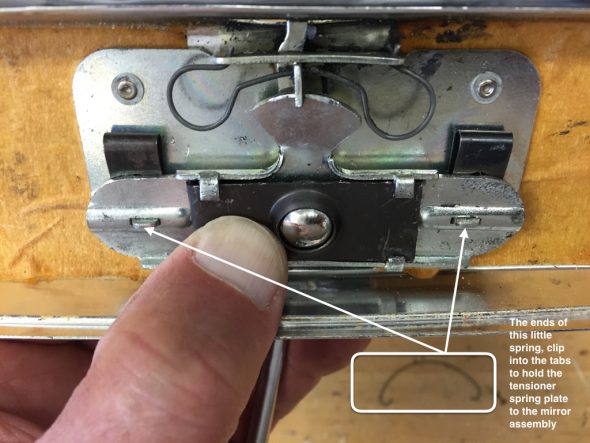
A very fine sprung wire holds the tensioner plate to the mirror assembly as seen in this image:

Rear View Mirror Retaining Spring

Rear View Mirror Retaining Spring

The mirror casing cleaned up with some polish and hand buffing:

Polished Mirror Casing

Polished Mirror Casing

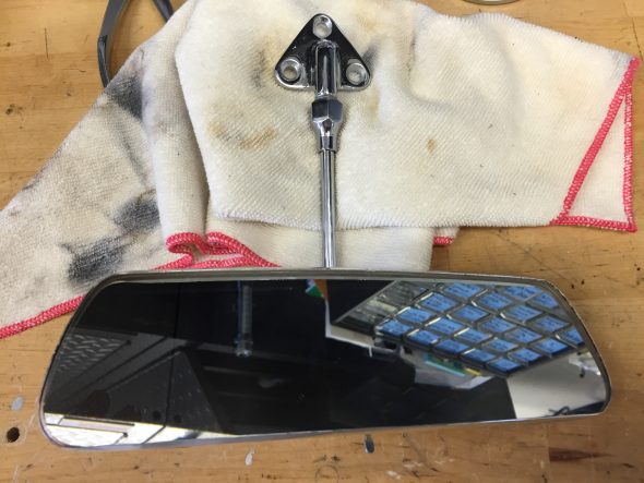
The final step was popping the mirror back into the casing to complete the job!

Resilvered Mirror Installed

Resilvered Mirror Installed

Of course, the generous use of Walnut veneered wood and supple leather hides make a Jaguar!

Wood Trim

I will have all of the wood professionally refinished. possible vendors include:

http://www.classicdashboards.com/gallery-jaguar-restoration-photos.html

Classic Dashboards is operated by Simon Lorkin who is located in France.

British Autowood operated by Saul Chaplin is in Altamonte Springs, Florida: http://www.britishautowood.com/index.htm


Leather Trim

I have not yet decided if I will have the leather and vinyl work custom stitched or if I will go with one of the primary suppliers:

John Skinner at: http://www.jaguar-trim.co.uk

or,

BAS Ltd. at: http://www.basjaguartrim.com/mk2daimler250.htm

or,

Aldridge Trimming at: http://www.aldridge.co.uk


Engine Mounting

Engine Mounting

Rear Engine Stabiliser

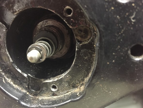
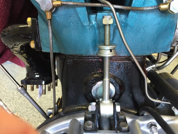
The rear of the engine is attached to the firewall (dash) of the car via a stabilising link with a rubber bushing and a rear mount on the firewall with a rubber bushing. I cleaned both components and installed new bushings.

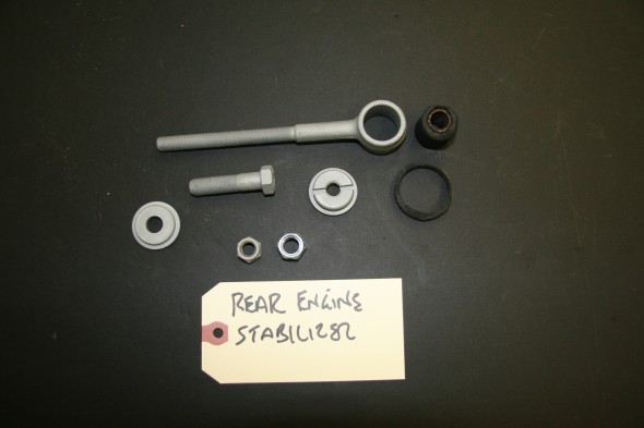
Stabilising Link at Rear of Cylinder Block, Bush, Stepped Washer, Stepped Bush, Nut

Stabilising Link at Rear of Cylinder Block, Bush, Stepped Washer, Stepped Bush, Nut

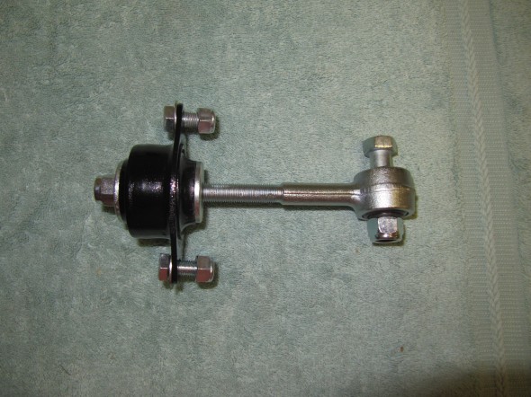
The rubber mounting for the stabiliser link needed to be replaced. I purchased a new one and had the link zink plated. This image shows the mounting and the link as an assembly.

Rear Engine Stabiliser Assembly

Rear Engine Stabiliser Assembly

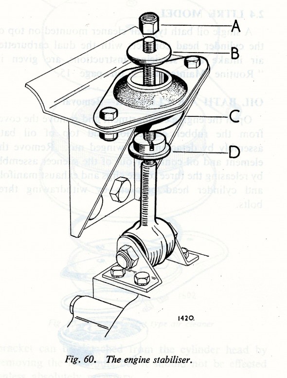
Engine Stabiliser

Engine Stabiliser

As can be seen in the illustration above, the stabiliser link is secured to the bell housing via two brackets, the LH and RH bearing brackets, mounting the stabilizing links at the bottom. The brackets are fastened to the bell housing with four 5/16 – 18 x 3/4″ hex bolts with lock washers. The link is fastened to the bracket with a single 7/16″ – 20 x 1-3/4″ hex head bolt with a nylock nut. The link is fastened to the firewall bracket using a stepped bush and stepped washer with a 3/8″ – 24 nylock nut.

Rear Engine Stabiliser Mounted

Rear Engine Stabiliser Mounted


Rear Engine Mount – The Channel Support Assembly

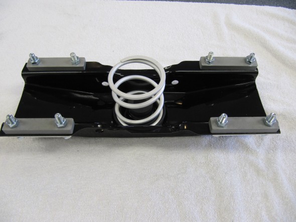
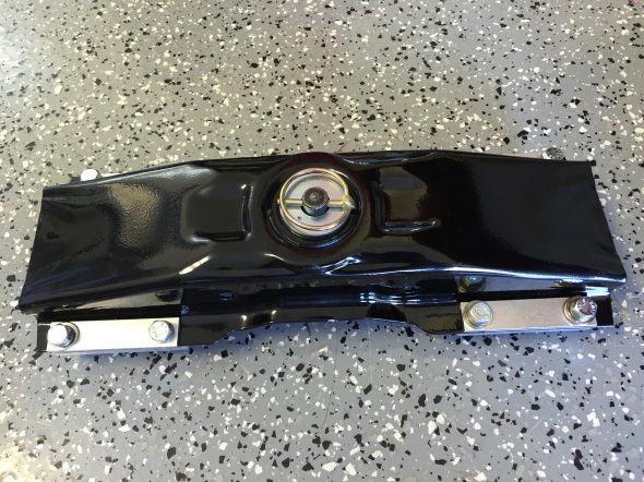
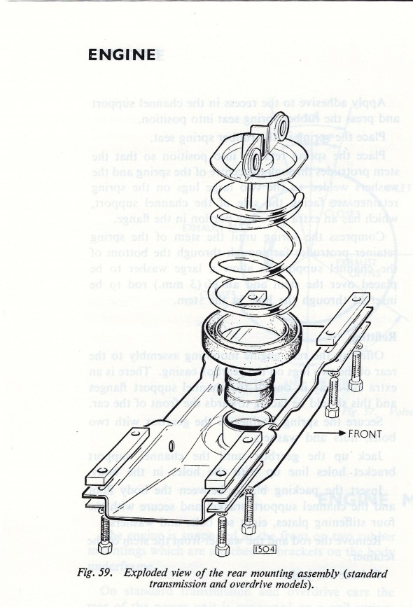
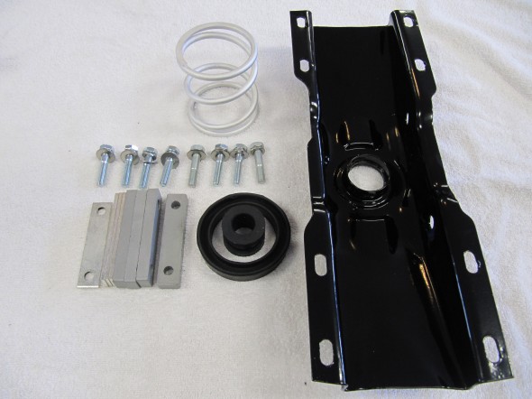
The assembly includes: The channel support, a rubber spring seat, a center rubber busing, the coil spring for rear engine mounting, four aluminum packing blocks between the flange of the channel support and the underside of the floor, eight bolts (5/16″ -24 x 1 3/8″), eight flat washers, eight split locking washers, and four stiffening plates. The Spring Retainer Assembly for Rear Engine Mounting is attached to the gearbox.

Rear Engine Mount

Rear Engine Mount


Engine Rear Mounting Assembly

Engine Rear Mounting Assembly

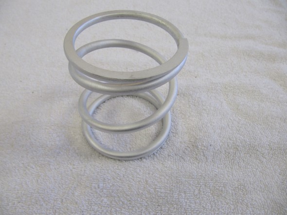
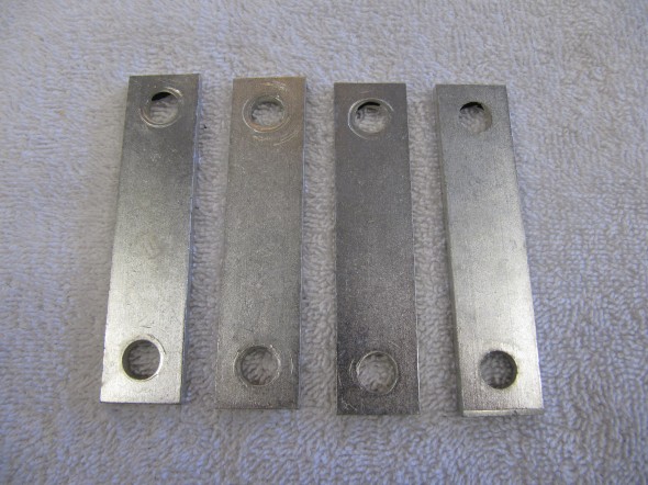
The rear engine mounting plate actually supports the tail of the gearbox and it bolts to the superstructure of the car. I cleaned and media blasted the Channel Support component of the assembly and powder coated it. The Assembly includes the channel support as well as its rubber spring seat, the rubber center bush, the spring retainer, the coil spring, the pin assembly, the bolt securing the rear engine mounting to the gearbox, a self-locking nut, four packing blocks and four stiffening plates. I replaced the rubber spring seat and the rubber center bush and the mounting fasteners with new components. The coil spring and stiffening plates were clear cad plated and the aluminum spacers were cleaned and clear-coated.

Support Assembly

Support Assembly

Coil Spring

Coil Spring

Support Stiffening Plates

Support Stiffening Plates

Channel Support Assembly Components for Rear Engine Mounting Assembled

Channel Support Assembly Components for Rear Engine Mounting Assembled

Reassembling and Installing the rear engine mount
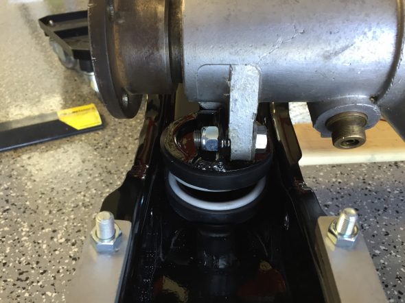
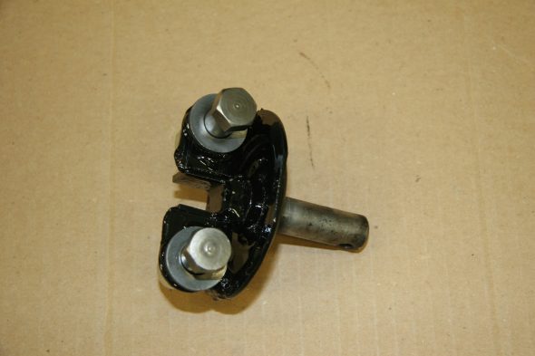
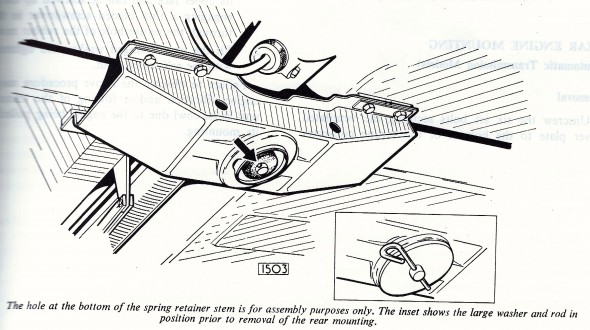
The Jaguar Service Manual provides instruction for installing the rear mount. Place the spring retainer into position so that the stem protrudes through the centre of the spring and the washers welded to the two large lugs on the spring retainer are facing the side of the channel support, which has an extra cut-away portion in the flange. Compress the spring until the stem of the spring retainer protrudes far enough through the bottom of the channel support to allow a large washer to be placed over the stem and an 1/8” (3 mm) rod to be inserted through the hole in the stem.” Of course, nothing is said about HOW to compress the spring. I found that I needed a press to do the job and it makes the task quite easy.

Rear Engine Mount with Pin Installed

Rear Engine Mount with Pin Installed

Rear Engine Mount Fixed to Gearbox

Rear Engine Mount Fixed to Gearbox

Spring Retainer

Spring Retainer

Two 7/16″-20 x 1-1/2″ hex head bolts with nylock nuts are used to secure the rear channel support (rear engine mount) to the gearbox. Note that the spring retainer needs to face the proper way as seen in the diagram and photos with the bolt heads to the front of the gearbox. The rear engine mount is now ready to old to the chassis with the eight (8) hex head mounting bolts.

Rear Engine Mount Attached to Gearbox

Rear Engine Mount Attached to Gearbox

Front Engine Mounts

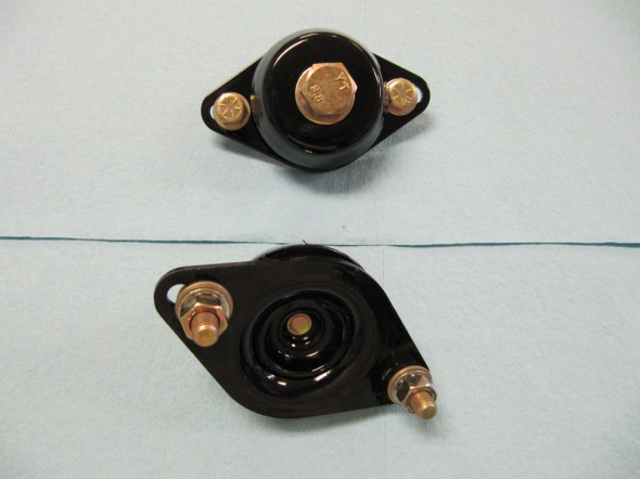
Upgraded engine mounts were ordered from SNG Barratt and were painted once received.

Upgraded Engine Mounts Painted

Upgraded Engine Mounts Painted

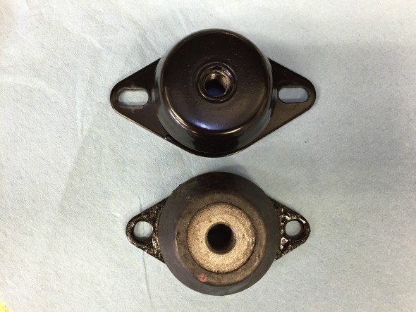
I wondered if the upgraded mounts were the same size as the original spec (but new) rubber mounts so I ordered a couple to see:

Upgrade Mount top and Original Spec Mount bottom

Upgrade Mount top and Original Spec Mount bottom

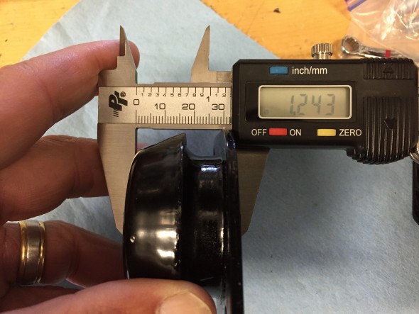
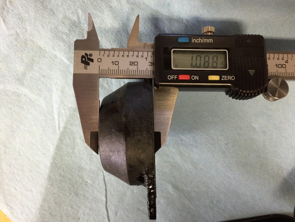
One can immediately see that the flange used to mount the rubber to the bracket is of a different shape and slightly wider, but it fits. Then to measure the height:

Upgraded Engine mount 1.243 inches High

Upgraded Engine mount 1.243 inches High

Original Spec Engine Mount 1.088 inches High

Original Spec Engine Mount 1.088 inches High

Hopefully this is not great enough difference to create a mounting problem. When I install the engine I will try the upgraded mounts first and see if they fit, but I have a fall-back if they do not.

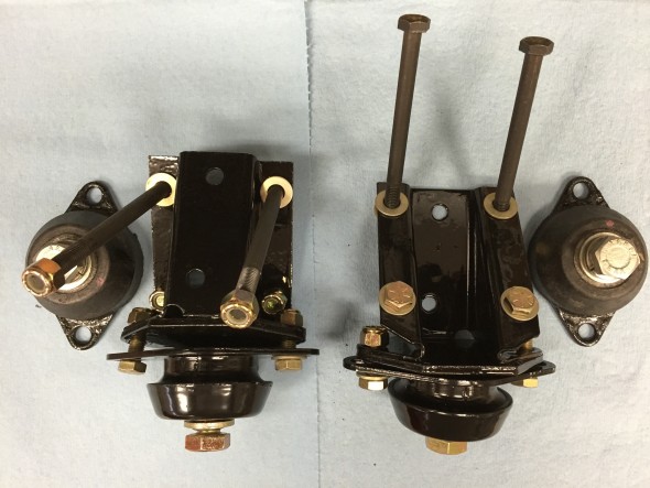
This is an image of the both brackets and rubber mounts ready to go on the car. I have used Grade 8 fasteners throughout. The rubber mounts attach to the flange brackets with 5/16″-24 x 1″ hex bolts and I have used nylock nuts. The bolts used in the rubber mount are 1/2″-20 x 7/8″ with split and flat washers. The two long bolts in each flange assembly are 5/16″-24 x 3 3/4″ while the shorter bolts are 5/16″-24 x 3/4″ and each is secured with a nylock nut and flat washer. The assemblies were blasted and painted with POR-15.

Bracket Assemblies with mounting rubbers and hardware

Bracket Assemblies with mounting rubbers and hardware

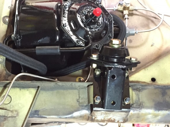
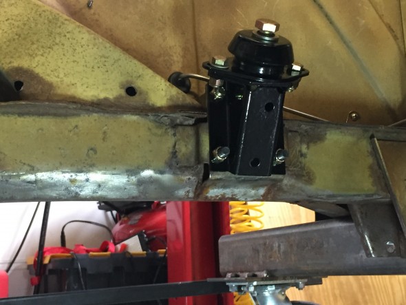
I am going to be installing the engine and gearbox before I complete bodywork and paint so I went ahead and installed the mounts to the car. I left the rubber mounts slightly loose as there is a little adjustability for mating with the engine. I will tighten after the engine is installed.

RH Motor Mounts Installed

RH Motor Mounts Installed

LH Motor Mounts Installed

LH Motor Mounts Installed

The Trial Engine Install

As mentioned in other posts under the “Restoration” heading of this site, my plan is to install the engine/gearbox, electrical system, front and rear suspension and etc.  so that I can test and run the major systems before I paint the car. So…. after getting everything in and tested I will then pull it all out, do the bodywork and paint and then reassemble. Crazy I know, but then no surprises after the car is painted.

Here is a short video I made of the install of the rebuilt engine. I used my lift to lower the car over the engine. You will note that I removed the LH engine mount and the exhaust manifolds – just to protect them since they have an expensive new porcelain coating now. On the RH side of the engine I removed the carburetors and their linkage, but left the oil filter and starter.

In a separate entry “Engine Post-Installation Check List” I will detail all of the connections and other items that must be tended to prior to starting the installed engine.

When I do this the final time and at the suggestion of a buddy and advisor, John Stefanik, I will leave the LH mount as well as the alternator and air conditioner compressor/mount and remove the RH mount and the oil filter. The alternator and compressor are not easy to mount once the engine is in the car. We will see. Anyway, here is my install video. Thanks to my wife and grandson for their assistance!

Accelerator Controls

Accelerator Pedal Assembly

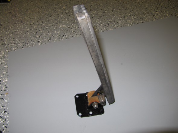
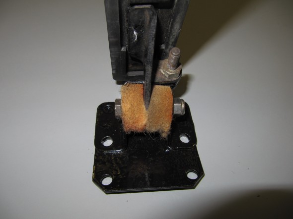
The accelerator pedal assembly was in good shape. I replaced the rubber pad on the accelerator pedal with a new one. I left the set screw restricting the pedal travel as it was found, as well as the two felt washers located at each side of the pedal boss.

The bracket assembly was cleaned and painted with POR 15. It is secured to the floor with four pointed 1/4″ – 28 x 5/8″ hex head bolts with split washers. The pedal is connected to the bracket with a 1/4″ fulcrum pin, flat washer and 1/4″ – 28 nylock nut.

Accelerator Pedal Assembly

Accelerator Pedal Assembly

Bracket Assembly, Mounting Accelerator Pedal to Floor

Bracket Assembly, Mounting Accelerator Pedal to Floor

Accelerator Shaft Assembly

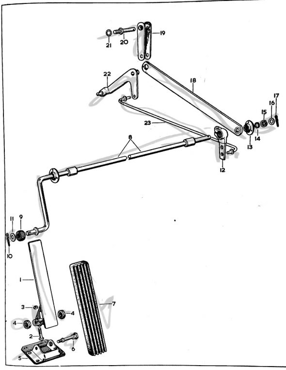
The image below depicts the components of the accelerator shaft assembly:

Accelerator Pedal Shaft Assembly Graphic

Accelerator Pedal Shaft Assembly Graphic

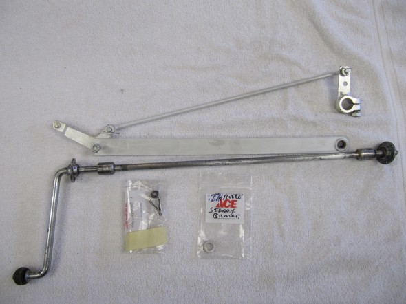
The shaft was slightly bent so I straightened, cleaned and polished it. The spherical bearing assemblies will be lubricated and reused and will be installed with new pop rivets to the body. The throttle lever, screws, spring washers and flat washers; the steady bar between the cross shaft housing and the connecting link; the bell crank lever assembly; and the control rod assembly were all cleaned and clear cad plated.

Accelerator Controls

Accelerator Controls

In anticipation of installing the engine into the car for testing, I installed the accelerator shaft assembly into the car. This would be more easily done prior to the installation of the steering column, but I was able to successfully work around it.

Having removed the split pin, flat washer, spring washer and the RH spherical bearing from the shaft, I inserted the accelerator shaft from the driver side into the engine compartment.

Installing the Throttle Shaft Assembly

Installing the Throttle Shaft Assembly

I then installed the throttle lever, the steady bar (with the bell crank lever, and the control rod assembly, linking the cross shaft lever and the bell crank lever), the RH spherical bushing onto the shaft and and slipped the shaft into the mounting hole on the RH side of the car.

Pedal Shaft Assembly

Pedal Shaft Assembly

Because I am only temporarily installing the throttle assembly in the car, I used #4 machine screws with flat washers, lock washers and nuts to hold the spherical bearings in place at both mounting points. Upon final assembly, pop rivets will be used.

RH Spherical Bearing in Place

RH Spherical Bearing in Place

In the passenger side (RH) footwell, I then slid the distance piece, spring washer, and flat washer onto the shaft followed by a split pin to secure the shaft assembly.

The assembly was then zip tied out of the way for engine install.

Accelerator Shaft Assembly

Accelerator Shaft Assembly

This is the LH side of the assembly prior to installing the accelerator pedal.

Accelerator Pedal Shaft Assembly and LH Spherical Bearing and Pedal Shaft Roller

Accelerator Pedal Shaft Assembly and LH Spherical Bearing and Pedal Shaft Roller

Finally, the pedal assembly described earlier was mounted to the driver’s side floor with four 1/4″ – 28 x 1/2″ hex head bolts with lock washers. These bolts are fastened into captive nuts welded to the floor underside.

Accelerator Pedal Assembly Mounted to Floor

Accelerator Pedal Assembly Mounted to Floor


Scuttle Ventilator

 Scuttle Ventilator Assembly

Ventilator Concept

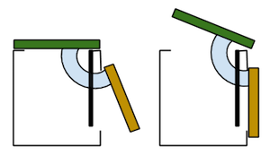
My fellow MK2 restorer Eric Kriss has a very nice diagram and explanation of its workings on his Blog. With all credit to Eric, this is an excerpt from his post on the topic:

Jag Scuttle ventilator

Jag Scuttle ventilator


“The beloved Jaguar scuttle ventilator, probably designed by Rube Goldberg himself, works in a somewhat counter-intuitive way. The vent lever operates a dual lid system.

When the top (horizontal, colored green) vent lid is closed, no fresh air enters the passenger compartment, but the vertical lid (colored tan) is open! When the top lid is open, the vertical lid closes, forcing fresh air into the scuttle plenum and out through the air distributor box.

Note that if the top vent lid is closed and the heater is running, hot air entering the plenum from the heater will also pass into the center instrument panel area. A rear ventilator shield (colored black) forces most of the hot air into the air distributor box, but this still warms the instruments … probably not a really great idea. Rain water can leak in the same way.”

Assembly Sequence

I did a trial installation of the Scuttle Ventilator Assembly in July 2014. The following sequence was used to install components:

  • Two door hinges
  • Weather shield
  • Torsion bar assembly, vertical race first
  • Operating arm
  • Scuttle lid
  • Lid mesh grille to lid

Scuttle Plenum

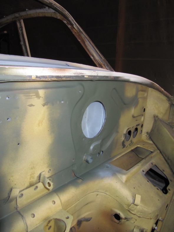
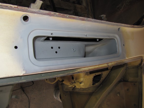
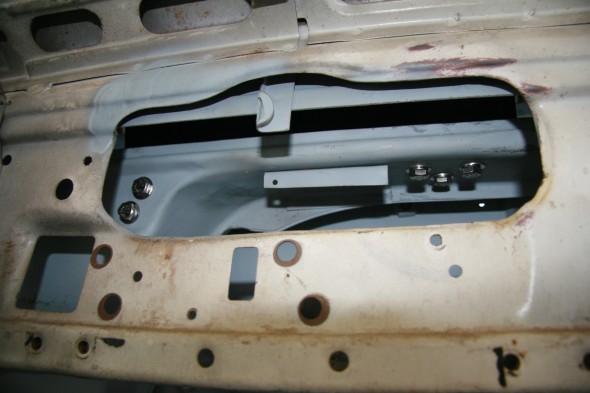
The plenum on my car was very rusty and given the location of the plenum it cannot be repaired in place. I was fortunate to locate a good used plenum and John Stefanik installed it for me. This effort also required some repairs to the firewall, and John accomplished all beautifully.

Plenum Firewall Repairs

Plenum Firewall Repairs

New "Used" Plenum Installed

New “Used” Plenum Installed

Operating Arm Assembly, for Scuttle Ventilator

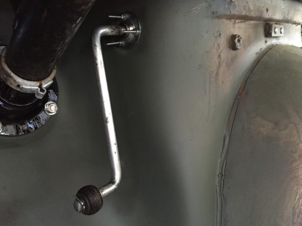
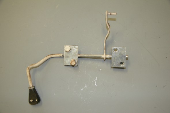
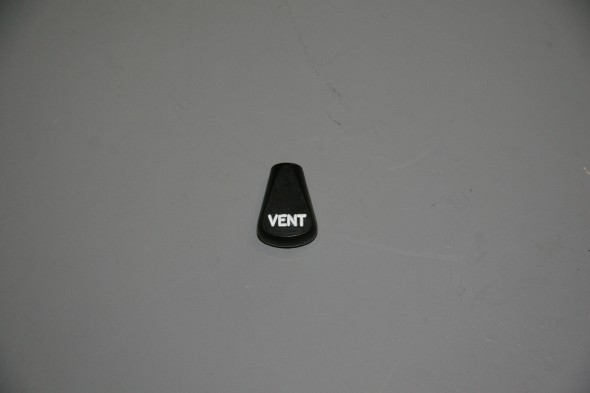
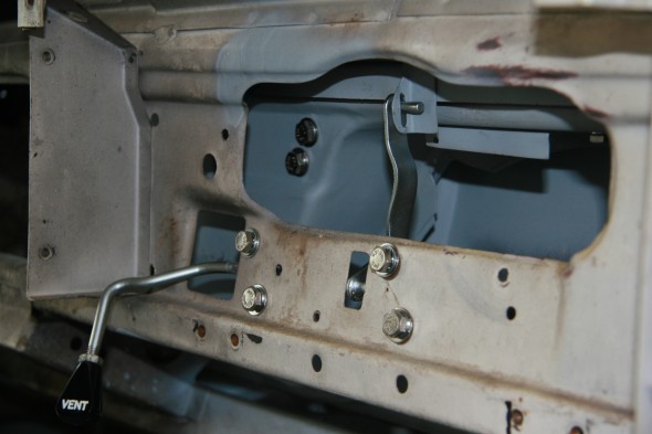
The Operating Arm Lever and knob were in great shape. It appeared that the car was painted at the factory after the Lever was mounted as the exposed parts of lever were body white, while the rest of it was zinc. The Lever cleaned-up nicely and was zinc plated. The Arm assembly mounts to the body shell with four 1/4″ – 28 x 1/2″ hex head bolts with split washers. The knob polished well and I repainted the “VENT” lettering. It’s position is adjusted using a 1/4″ – 28 lock nut.

I assembled the Scuttle Ventilator and installed it as a trial for fit and operation. Everything worked beautifully.

Operating Arm Assembly, for Scuttle Ventilator Lid

Operating Arm Assembly, for Scuttle Ventilator Lid

After a little polishing and a lettering “touch up” with some white modeling paint, the knob for the operating arm assembly looked as good as new.

Scuttle Vent Operating Arm Knob

Scuttle Vent Operating Arm Knob

Operating Arm Assembly, for Scuttle Ventilator Lid Trial Fitting

Operating Arm Assembly, for Scuttle Ventilator Lid Trial Fitting


Torsion Bar Assembly for Ventilator Lid 

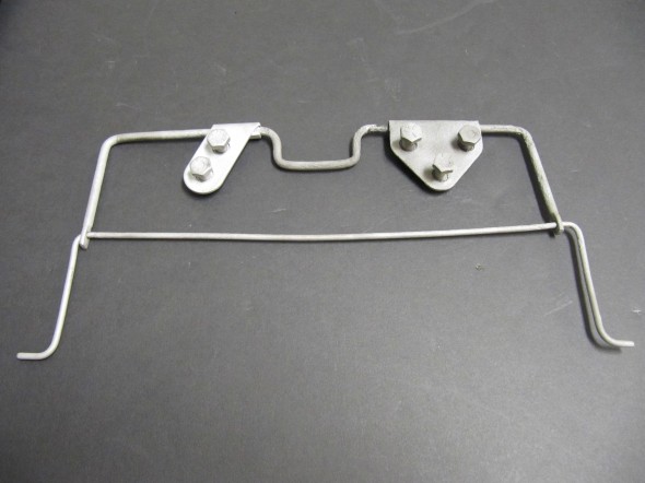
This piece was very rusty but after soaking in a rust treatment, blasting with aluminum oxide, and the application of heat with a torch to the pivot points, I got it operational and I believe that it is strong enough to be used as is. I painted it with POR-15 and will hope for the best. The part is not available from the usual vendors.

I installed it as part of the trial fitting of the scuttle ventilator assembly and while it is not visually pretty, it appears that this part has been successfully saved. The Assembly mounted with five 1/4″-28 x 1/2″ hex head bolts, shake proof and flat washers. It is easiest to mount the vertical brace (to the left in the image below) first and then the piece with the three bolts.

Torsion Bar Assembly for Ventilator Lid

Torsion Bar Assembly for Ventilator Lid

Torsion Bar Assembly for Ventilator Lid

Torsion Bar Assembly for Ventilator Lid

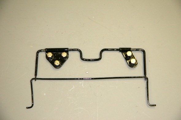
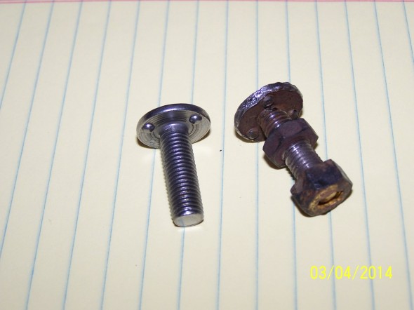
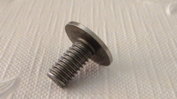
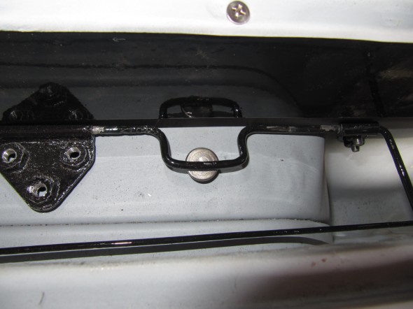
In the photo below, the weld stud that screws into the nut at the bottom of the plenum has not yet been installed. My fellow MK2 restorer and part hunter extraordinaire, Robert Seligman, somehow tracked down a source for the weld stud. http://www.jhpfasteners.com/5/16-weld-stud-with-projections-under-head-p-5614-l-en.html

Apparently the stud was screwed in an upward direction to create more pressure if it was needed on the torsion bar assembly. Oddly, the stud is double-nutted with the lower nut welded so as not to loosen.

New and Original Weld Stud

New and Original Weld Stud

Plenum Weld Stud

Plenum Weld Stud

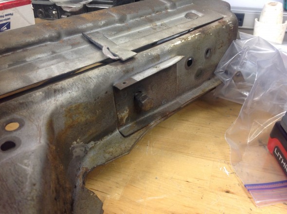
Adjusting nuts on bottom of Plenum

Adjusting nuts on bottom of Plenum

Weld Stud Installed in Plenum to adjust Torsion Spring

Weld Stud Installed in Plenum to adjust Torsion Spring

Torsion Bar Assembly for Ventilator Lid Trial Fitting - Mounting Bolts

Torsion Bar Assembly for Ventilator Lid Trial Fitting – Mounting Bolts

Rubber Seal on Recirculating Door on Scuttle Face Panel

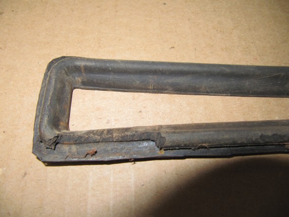
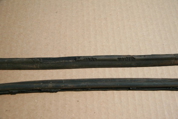
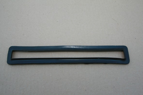
I was going to install a new rubber seal, but discovered that new stock is not obtainable. So I took a look at my original to see if it could be saved. I recalled that there were some tears in the rubber but I was hopeful. Upon close inspection I found not tears, but several places where mice had chewed and eaten the rubber. Those bastards eat anything – rubber seals and wire insulation have great nutritional value I am sure!

Rubber Seal on Recirculating Door on Scuttle Face Panel Rounded Side

Rubber Seal on Recirculating Door on Scuttle Face Panel Rounded Side

Mice Teeth Marks

Mice Teeth Marks

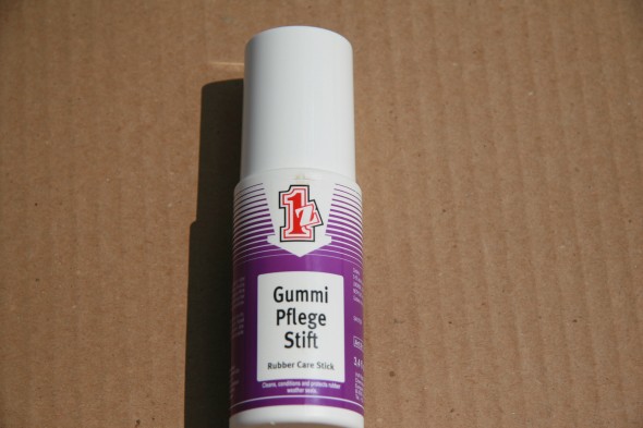
I checked into rubber rejuvenation and a German product called Gummy Pflege Stift was recommended.I ordered and tried it and found it to be quite good. The seal is now clean soft and pliable. The surface that mates with the door is in good shape so I think I will be able to use this seal.

Gummi Pflege Stift

Gummi Pflege Stift

Rejuvinated Plenum Seal

Rejuvinated Plenum Seal

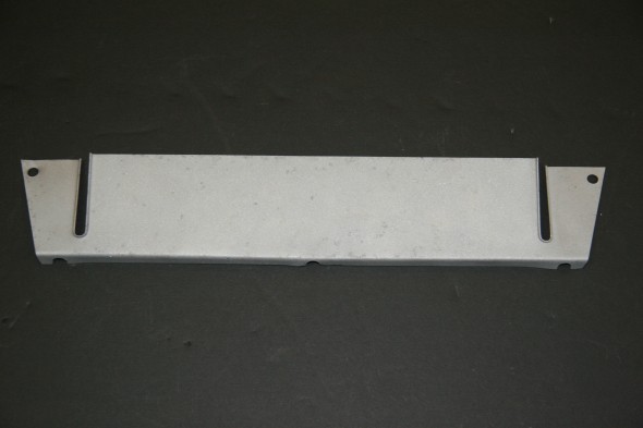
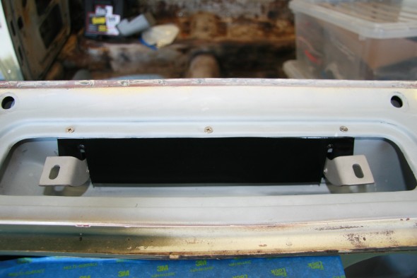
Rear Shield for Scuttle Ventilator Assembly

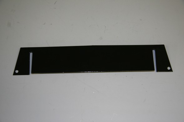
I don’t know the proper name for this component of the assembly. But, I  media blasted it and had it powder coated. This piece is a little tricky (not hard) to install. It used three flat head 2BA 3/8# screws and square nuts originally. Square nuts are used because the flange on the piece is used to tighten the screws. I found it easiest the start the nut on each screw, push the piece under the scuttle but above the nut, and then tighten each screw.

Rear Shield for Scuttle Ventilator Assembly

Rear Shield for Scuttle Ventilator Assembly

Powder Coated Rear Shield for Scuttle Ventilator Assembly

Powder Coated Rear Shield for Scuttle Ventilator Assembly

Scuttle Assembly Shield Mounted to Scuttle

Scuttle Assembly Shield Mounted to Scuttle

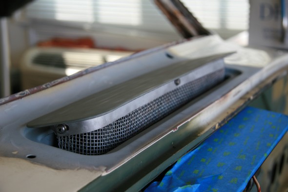
Scuttle Ventilator Lid and Wire Mesh Grille

A couple of the mounting screws for my original lid broke when I tried to remove it from the car. Fortunately, I was able to locate another lid which worked fine with my original wire mesh grille. The lid is installed first then the grille is added. The lid attaches to the hinges with captive #10-32 machine screws which are quite long, perhaps 1 inch. The length is to facilitate the mounting process. As one can see in the image above, there is adjustment for and aft for the lid. I suppose washers could be used to raise the height of the lid if needed.

The wire mesh grille is mounted to the lid with three phillips head #10-32 x 1/2″screws. I found it easiest to insert the front center screw first followed by the side screws. The mesh grill is properly painted the color of the car.

Scuttle Ventilator Assembly Lid and Wire Mesh Grille - Trial Fitting

Scuttle Ventilator Assembly Lid and Wire Mesh Grille – Trial Fitting

The Scuttle Plenum has a drain tube at its bottom and a rubber drain hose is mounted to the tube. The drain hose simply drains to the ground below the car. The image below shows a trial fitting of the hose. Unfortunately, it is a bit difficult to make out in the photo. It is the large hose that exits to the transmission tunnel.Plenum Drain Hose


New Wiring Harness Planning & Prep

Wiring harness Installation Disclaimer

After selecting the fuse/relay panel from Classic Technologies to be the heart of my new electrical system, the next issue was to decide about the wiring harness to be used. I could either select a pre-assembled harness from one of a number of vendors, knowing that I would have to modify it given the “personalizations” I would be incorporating, or I could build my own.

I decided to build my own. I must give credit where credit is due. I don’t know if I would have made the decision I did had I not known that Eric Kriss would also be concurrently (almost) building a new harness for his MK2. Eric’s knowledge of automotive electrical systems far surpasses my own, but I have courage and a desire to learn! Eric willingly shared his design work and I put his schematics to good use.

Marc Goldblatt from Classic Technologies who provided the relay/fuse box I am using provides a wonderful color wiring diagram that is also extremely helpful. Between Eric and Marc I felt pretty positive about venturing into the wiring world!

Undertaking this project is a big task that requires significant planning and advance preparation.

Advance Preparation – Out with the Old

I spent days “deconstructing” my MK2’s wiring harness and taking copious notes about the various gauges, switches, components, wire sources and terminations. While this step may not have been necessary, I learned volumes about the principles of wiring. Having a good wiring schematic is particularly helpful. There are a number of “after-market” exploded wiring charts available. The best one I found was by [email protected]What is really nice about his schematic is that a vertical and horizontal legend is incorporated making it much, much easier to locate a component on the schematic than otherwise.

Tools and Materials

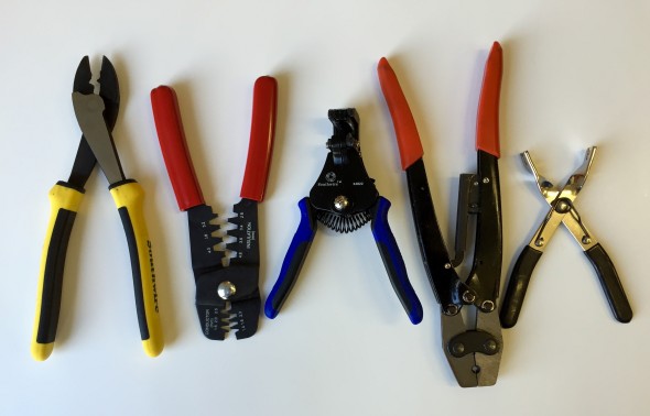
There are some “tools of the trade” that are really needed to do a good job with electrical connections. Using the proper tool also generally makes the job easier!

The crimper on the left makes easy work of crimping wire in insulated terminals. I used these extensively on my 14 and 18AWG wire. The next set of crimpers from the left side of the image are for pin and socket terminals used in Molex Connectors. Something like these are essential for a good job. Third from the left is a wire stripper and I could not imagine taking on a wiring job without these. Fourth from the left is a ratchet style crimper used for bullet terminals. Finally, snap connector pliers to push together 2-4 bullet terminals in snap connectors. Of course, one can always find and use more tools, but I regard these as the necessary for rewiring my Jaguar MK2.

Crimpers & Strippers

Crimpers & Strippers

Terminals and Connectors

Most of my wiring is 18 and 14 gauge wire. I used a combination of bullet connectors and insulated spade terminals (male and female) to connect wires. Bullet connectors for the two sizes of wire are shown to the left below. Various sizes of snap connectors are also shown. These are available from British Wiring in Bally, PA. This company is very responsive and helpful.
Bullet Terminals and Various Size Snap Connectors

Bullet Terminals and Various Size Snap Connectors

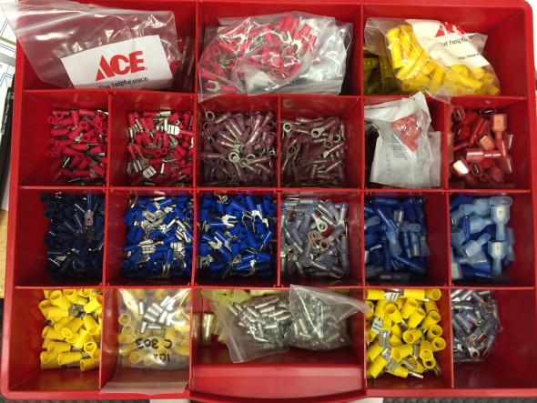
I put together a storage kit of various types and sizes of vinyl terminals to use on this and other projects:Wiring Connector Terminals
I ordered most of my connectors and terminals from Waytek, Inc., similar products are available from other suppliers but I was pleased with Waytek’s comprehensive inventory and selection. The one downside to Waytek is that for many parts you may have to order more of a particular item than you want or need – that is when the local ACE Hardware store comes in handy.

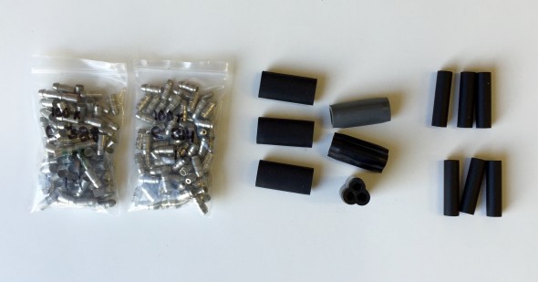
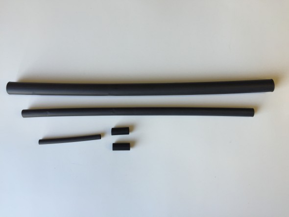
I suppose that it is not essential, but for many of my wiring connections I like to use shrink tubing to create a safe and good looking joint. A little heat from a heat gun or a flame and in seconds you have a very professional looking connection. British Wiring has many sizes of shrink tubing but it is also available from many other vendors.
Shrink Tubing
Shrink Tubing
Wire Labeling

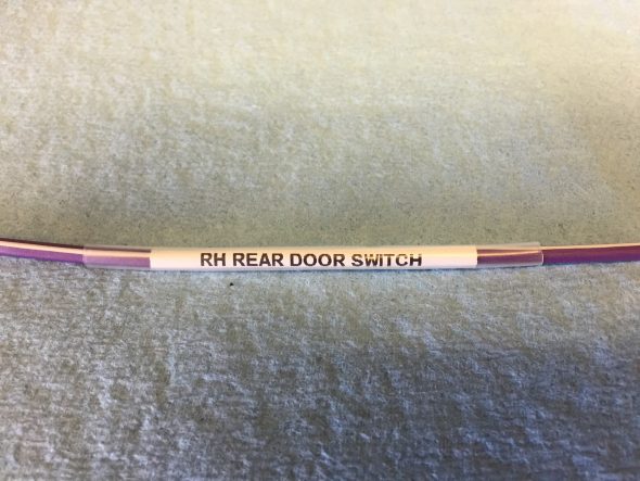
Not in every case, but in most, I have labeled wires for future troubleshooting and as a reference guide. I used a DYMO LetraTag LT-100H Electronic Label Maker to make my labels and covered them with clear shrink tubing sourced from Pegasus Racing. A little heat on each of the label and it is sealed from the elements.

Wire Labeling

Wire Labeling

DYMO LetraTag LT-100H Electronic Label Maker

DYMO LetraTag LT-100H Electronic Label Maker

Barrier Terminal Blocks

Eric Kriss’s wiring plan, where possible, eliminates both long wiring runs and the use of the original snap “bullet connectors” by utilizing modern barrier terminal blocks as intermediate wiring connection points. This approach makes testing and chasing wiring problems considerably more straightforward and accessible when contrasted with the original wiring harness. Further modifications are also more easily accommodated. The trade-off is a bit more complexity in designing the harness.

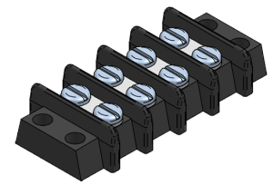
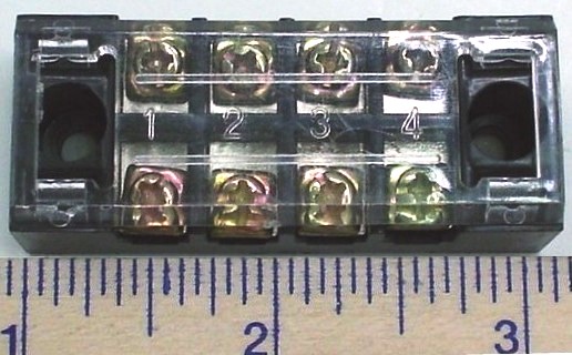
The barrier blocks come in various sizes, some with clear plastic caps and others without.

Typical 4-gang Barrier Block

Typical 4-gang Barrier Block

In my design I used one 12 gang barrier block and one 6 gang barrier block under the dash, below the steering wheel on the left side of the car. Under the dash on the RH side a single 6 gang barrier block was used.

In the engine bay (and inspired by Eric Kriss’s work), hidden by the original fuse assembly cover, are three 4 gang barrier blocks with clear plastic covers.

Barrier Block with cover

Barrier Block with cover

Finally one, small 4 gang barrier block, secured with velcro, was used in the central instrument panel assembly wiring.

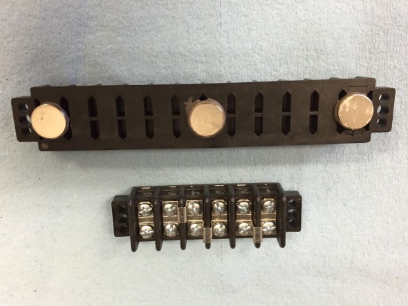
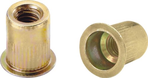
Only time will tell if I made a good decision or not, but rather than mounting the under dash barrier blocks with self-tapping or machine screws, I epoxied strong magnets to the back side of the blocks making it possible to easily remove them from their location to ease access to connections. Rivet nuts and machine screws were used to fasten the barrier blocks in the engine bay.

Barrier Blocks with Magnets

Barrier Blocks with Magnets

Rivet-Nuts

Rivet-Nuts

Wire 

I ordered my wire from British Wiring. I began with the good intention of following British standard wiring codes, but to minimize waste I admit to ending up using wire colors that did not follow convention. However, all was well documented.

Lucas Wiring Color Codes

Mike McPhail, the president of the South Texas Austin-Healey Club, published an article in the July, 2010 issue of Regional Rumblings, the Club’s newsletter that provided an excellent color coded summary of Lucas wiring that  proved helpful with the Jaguar as well. I didn’t always follow convention (for economy) but it is useful to know what you are supposed to be doing!

Lucas Wiring Color Codes

Testing Equipment

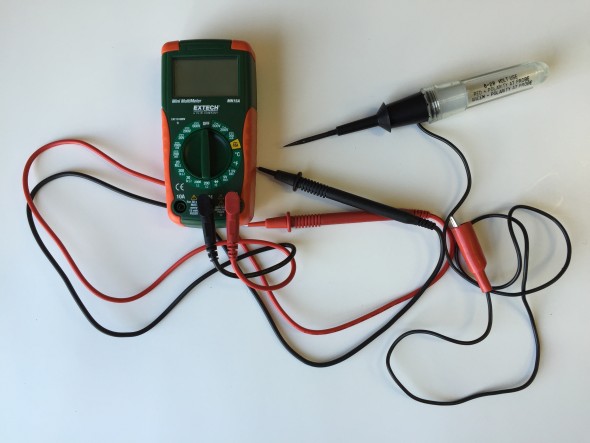
Testing connections and trouble shooting is always necessary. Whether simply checking for continuity or determining voltage or amperage a few appropriate tools are needed. I would suggest these two at a minimum:

Multimeter and Circuit Tester

Multimeter and Circuit Tester

New Wiring for Switches and Gauges

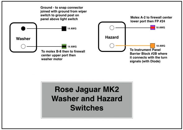
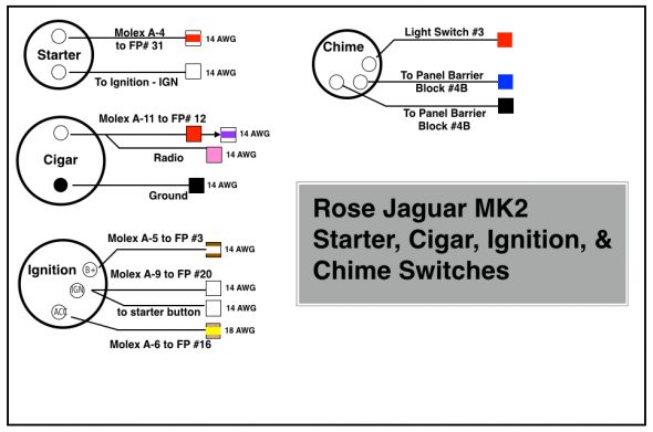
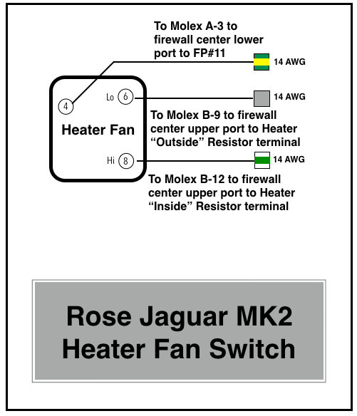
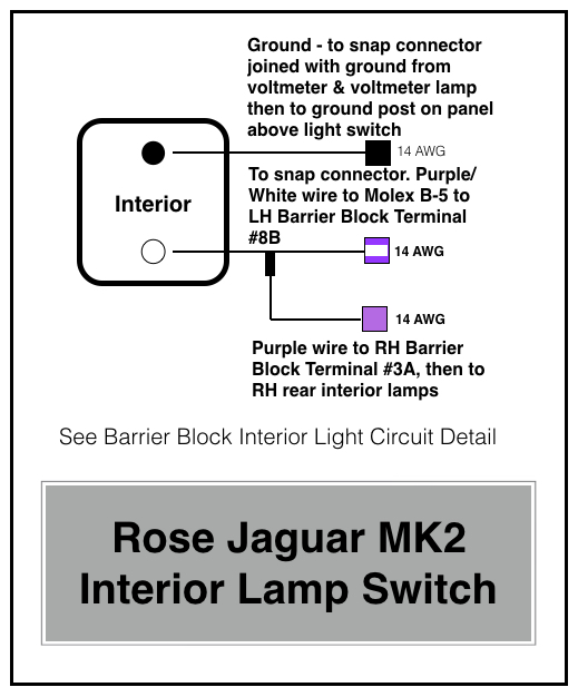
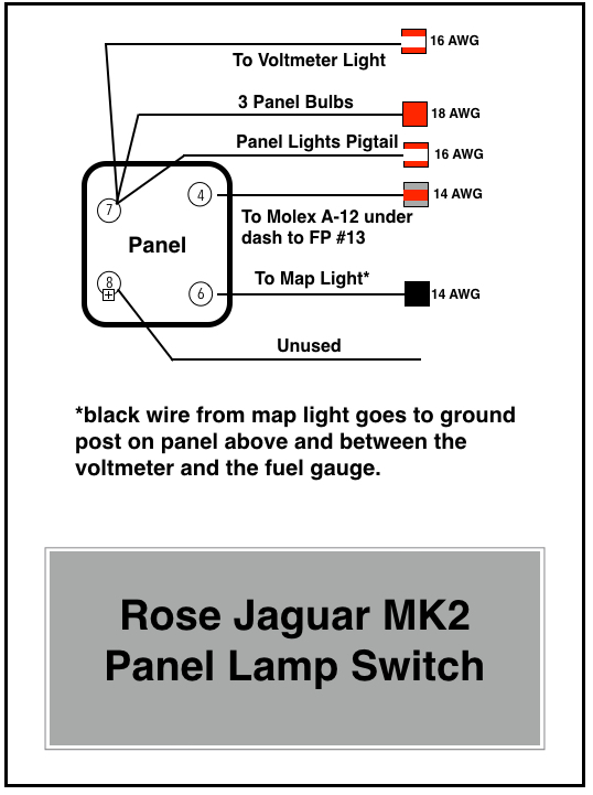
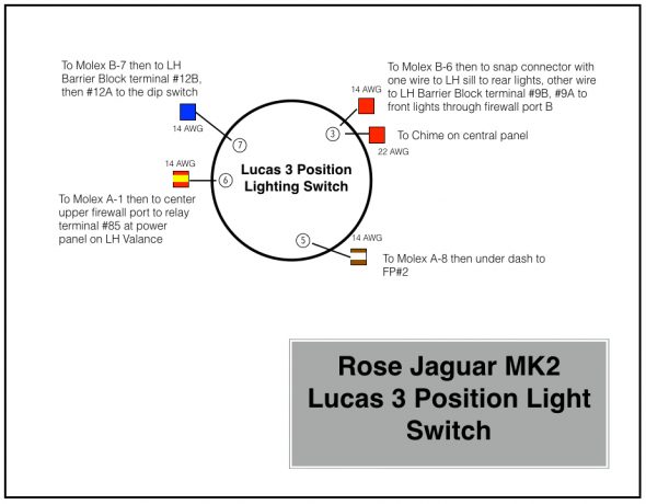
The diagrams provided below depict the wiring to/from each of the switches in the panel. The purpose, operation and in some cases repurposing of the switches is described in a previous post “Gauges, Instruments and Switches.” One addition to the panel is a small chime that is activated if the headlamps are left on when the ignition is off, but the driver’s door is opened.

Rose Jaguar MK2 Washer and Hazard Switches

Rose Jaguar MK2 Washer and Hazard Switches

Rose Jaguar MK2 Wiper Switch

Rose Jaguar MK2 Wiper Switch

Rose Jaguar MK2 Starter, Cigar, Ignition, & Chime Switches

Rose Jaguar MK2 Starter, Cigar, Ignition, & Chime Switches

Rose Jaguar MK2 Heater Fan Switch

Rose Jaguar MK2 Heater Fan Switch

Rose Jaguar MK2 Interior Lamp Switch

Rose Jaguar MK2 Interior Lamp Switch

Rose Jaguar MK2 Panel Lamp Switch

Rose Jaguar MK2 Panel Lamp Switch

Rose Jaguar MK2 Lucas 3 Position Light Switch

Rose Jaguar MK2 Lucas 3 Position Light Switch

Instrument Panel Assembly Gauge Wiring

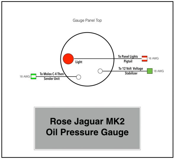
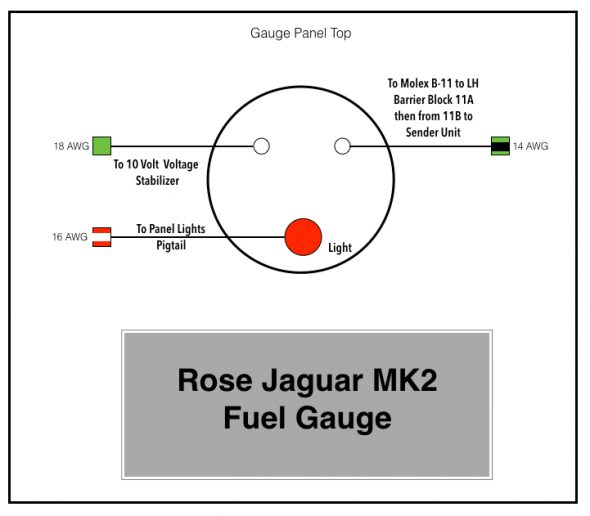
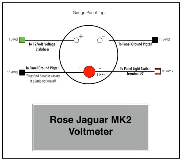
There are four gauges located in the central instrument panel assembly: from left to right when looking at the face of the panel, the water temperature gauge, the oil pressure gauge, the fuel gauge, and the voltmeter which is substituted for the original ammeter. As with the switches, the gauges are explained more fully in the “Gauges, Instruments and Switches” post.

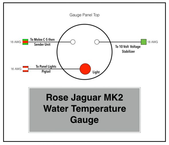
The following images depict the wiring for each of the four gauges:

Rose Jaguar MK2 Water Temperature Gauge

Rose Jaguar MK2 Water Temperature Gauge

Rose Jaguar MK2 Oil Pressure Gauge

Rose Jaguar MK2 Oil Pressure Gauge

Rose Jaguar MK2 Fuel Gauge

Rose Jaguar MK2 Fuel Gauge

Rose Jaguar MK2 Voltmeter

Rose Jaguar MK2 Voltmeter


Interior Lights

Conversion to LED lights

The Jaguar Mk2 and all other cars of the period used incandescent bulbs in the interior fixtures and gauges. In my restoration I intend to replace most if not all incandescent lights with light emitting diodes or as they are more commonly referred to: LEDs.  LEDs live longer, use considerably less power, and are brighter than the incandescent bulbs they replace. Specific light model numbers and quantities are listed with the various installations below. The LED lights were sourced from 4 Sight Automotive, www.bettercarlighting.co.uk

Interior Courtesy Lights

I will collectively refer to the interior lamp in rear quarters, the interior lamp at top of center pillars, and the headrest lamps as courtesy lamps. The MK2 did not have seat headrests, much less headrest lights, but I am using front seats from what I believe was a 1990 jaguar XJ 40. In 1990 the headrest lamps were connected to a central computer, but obviously, there is no computer in a 1964 Jaguar.

The rear quarter and the center pillar lights were designed to be activated by opening any one of the four doors in which case a door switch would illuminate the lights and extinguish them when the door was closed. Alternatively,  flipping the “INTERIOR” toggle switch on the central gauge panel to the “on” position also illuminates the lights. In my wiring methodology this pattern is retained.

Both of my center pillar lights were broken. They are held together by two metal pins with balls on the ends that snap into the plastic lens. After fifty years the plastic is fragile and very susceptible to breaking. The chrome “shields” are secured to the assembly with two folding tabs that are also fragile and easily broken.

A modern replacement is available and I sourced them from SNG Barratt. The new units solve the design problems of the earlier model but unfortunately have visible screws through the shields and the backplate is black plastic rather than chrome metal. All disappointing!

The new units do have an on/off switch on the bezel of the lamp.The on/off switch on the lamp acts exactly like the toggle switch on the central gauge panel. That is, when the on/off switch is turned on, all four lights illuminate.

B/C Pillar Interior Lights

B/C Pillar Interior Lights

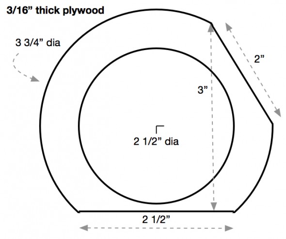
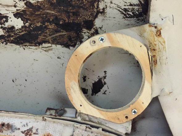
Unlike the Center Pillar lights, the new stock replacements for the rear lights appear identical to the originals. I substituted 36MM LED festoon bulbs in warm white from 4Sight Automotive for the original incandescent bulbs. Each of these lamps mount to a plywood frame and then to the body of the car. My original plywood pieces simply fell apart when I disassembled the car. New wood frames were made per the pattern supplied by Eric Kriss on his web site. I then trial fit the plywood frame and lamp fixture. The plywood is held to the metal body with two #4 X 1/2″ flat head self tapping screws, and then the lamp body is secured through the plywood to the metal body with two #4 x 3/4″ self tapping screws.

Rear Quarter Interior Lamps Plywood Mounting Frame

Rear Quarter Interior Lamps Plywood Mounting Frame

New Plywood Frame for rear quarter interior lamp

New Plywood Frame for rear quarter interior lamp

New Rear Interior Lights

New Rear Interior Lights

New Rear Interior Lights

New Rear Interior Lights

rear quarter interior lamp with LED inserted

rear quarter interior lamp with LED inserted

LH rear quarter interior lamp

The seat headrest lights were originally wired in such a way that they too illuminated when the car’s doors were opened. These lights also have an integral on/off rotary or dial switch. Without the central processor of a more modern car it would be all too easy to leave these lights on and eventually drain the battery. Therefore, I elected to wire these lamps to a switched power source rather than a constant power source like the other lamps. I did not use the terminal on the headrest light that would normally have a red/green wire to the door switches.

XJ40 Headrest Lamp

XJ40 Headrest Lamp

XJ40 Headrest Lamp 1

Once the ignition is turned on the front seat headrest lights behave like the other courtesy lamps, but if the ignition is off, unlike the other lights, the  headrest lights cannot illuminate. Consequently no drain on the battery.

While not the same as the original Jaguar MK2, nor the Jaguar XJ40, I believe this wiring approach produces a very satisfactory result.

Instrument/Gauge Panel Lights

The lights on the gauges and the illumination of the switch markings is controlled by the switch lever marked”Panel” on the gauge panel. The switch has two positions “DIM” and “BRIGHT” to suit the driver’s requirements. The panel lights will only operate when the sidelights are switched “ON.”

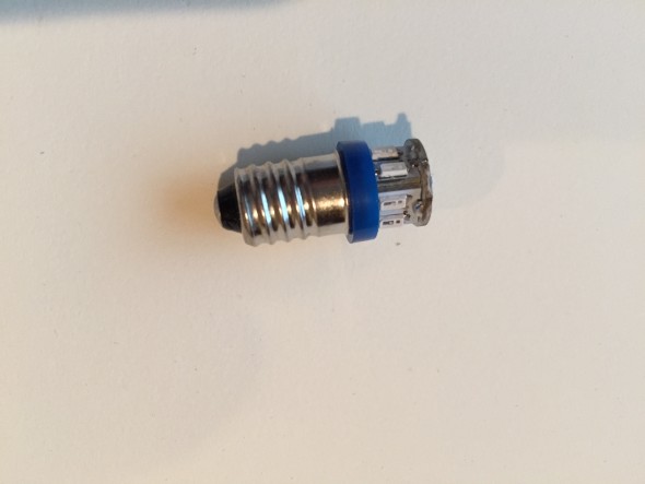
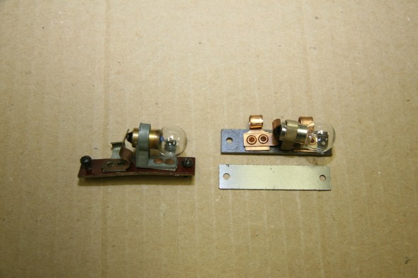
All of the original 987 incandescent bulbs in the eight panel lights will be replaced with BA9 ES Neg. (screw base) LEDs (The image below shows a blue bulb, but I actually used white).  Two each in the speedometer and tachometer, and one each in the fuel, water temperature, oil pressure, and voltmeter gauges.

BA9ES Blue Neg LED

BA9ES Blue Neg LED

Warning Lights

There are four warning lights on my MK2. Three are located in the speedometer for fuel level, ignition, and high beam headlights. An additional light on the dash warns for low brake fluid or the handbrake application. These incandescent lights are replaced with BA9ES white Neg LEDS.

Map Light

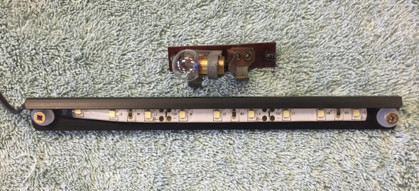
There is a lamp located above the instrument panel, mounted to the wood screen rail capping. As designed, to illuminate the lamp, the switch marked “MAP” is lifted. The light will only operate when the sidelights are switched “ON.” However, following the lead of Eric Kriss I have repurposed the map light toggle switch to control the hazard light function. The map light in my wiring scheme is controlled by the panel lamp switch. I also substituted an LED strip in place of the original incandescent bulb. Details about the wiring are available at the “building a new wiring harness” post and at the “Gauges, Instruments and Switches” post.

Map Light

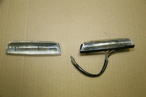
Map Light – Original and New Replacement

Original Incandescent map light and LED Map Light

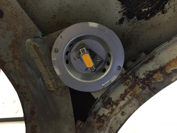
Original Incandescent map light and LED Map Light

“Cubby” Glove Box Light

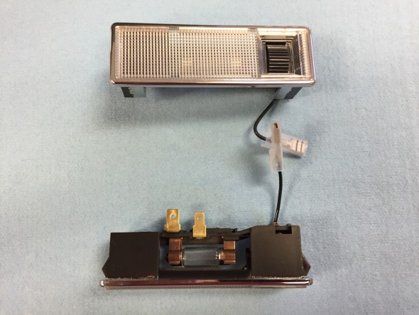
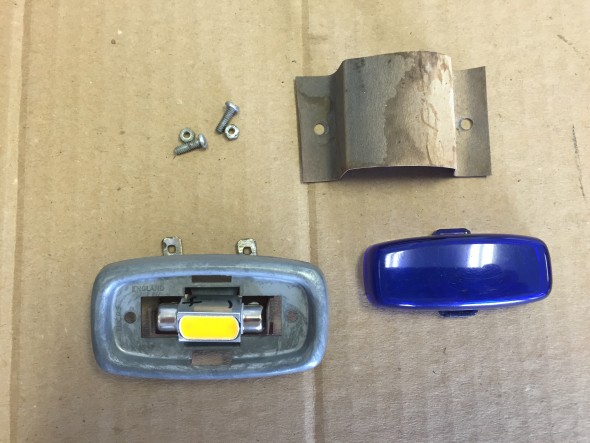
As designed, the lamp in the glove box is automatically illuminated when the door is open and the side lights are “ON.” However, following the lead of Eric Kriss, I have wired the cubby lamp and the luggage lamp in the boot so they will illuminate when the cubby door is opened or the boot lid is opened without the necessity of turning on the lights at the light switch first. As with the other lamps the incandescent bulb has been replaced by an LED lamp. the following image shows the components of the lamp.

Cubby Box Lamp

Cubby Box Lamp

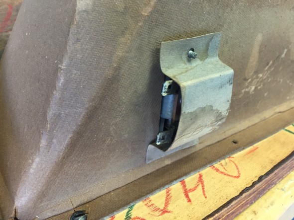
Cubby Box Lamp installed in Box

Cubby Box Lamp installed in Box

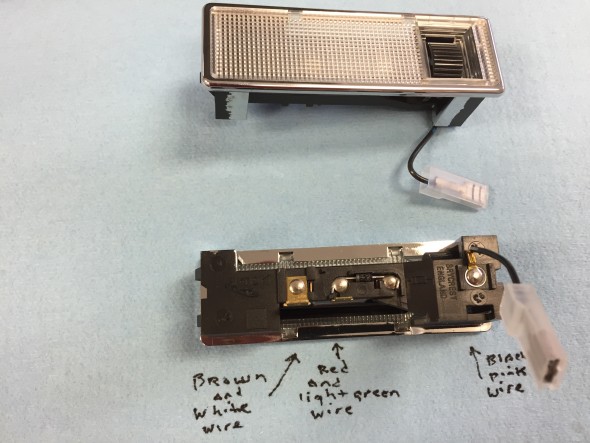
The following image shows the components of the cubby lamp switch.

Cubby Box Switch

Cubby Box Switch

Luggage Compartment Light

The Boot is illuminated when the lid is opened. The lamp only operates when the side lights are switched “ON.”

Luggage Compartment Illumination

Luggage Compartment Illumination