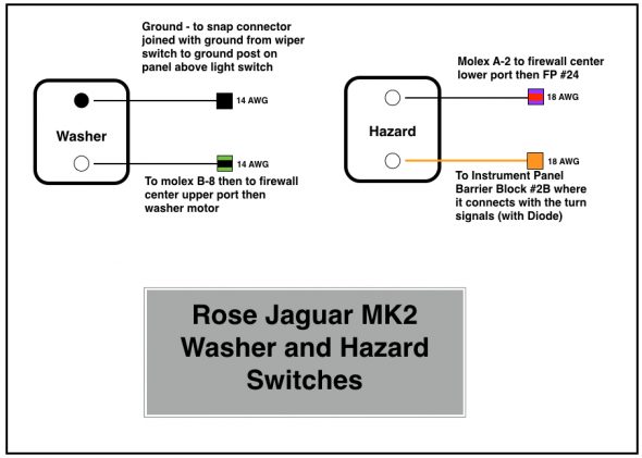
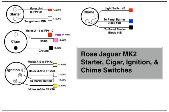
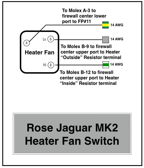
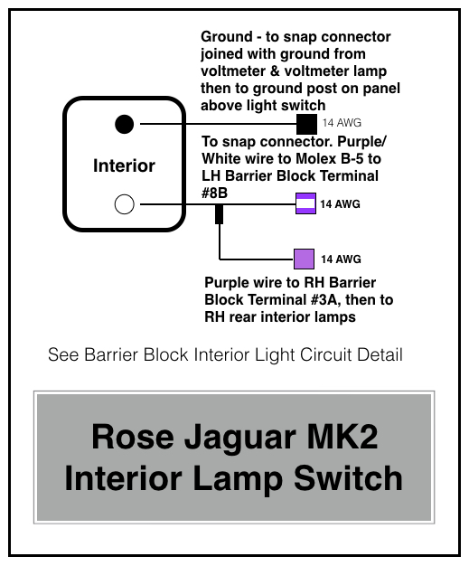
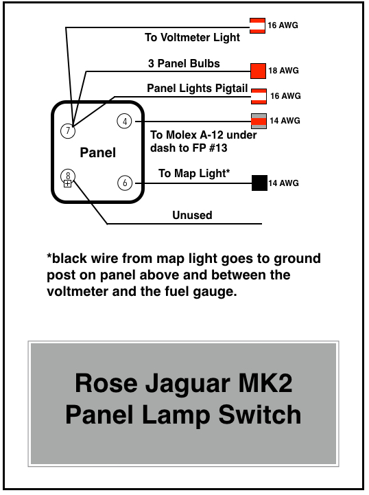
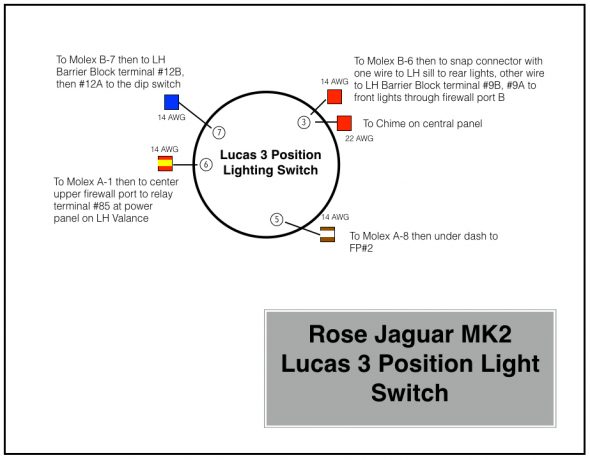
The diagrams provided below depict the wiring to/from each of the switches in the panel. The purpose, operation and in some cases repurposing of the switches is described in a previous post “Gauges, Instruments and Switches.” One addition to the panel is a small chime that is activated if the headlamps are left on when the ignition is off, but the driver’s door is opened.
Instrument Panel Assembly Gauge Wiring
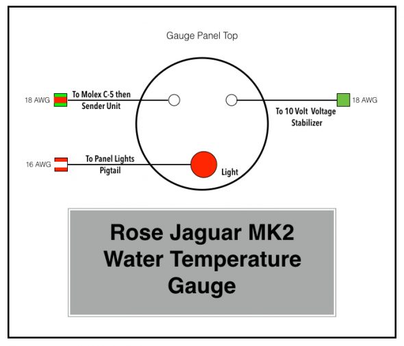
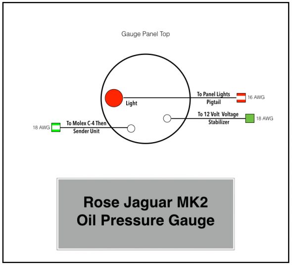
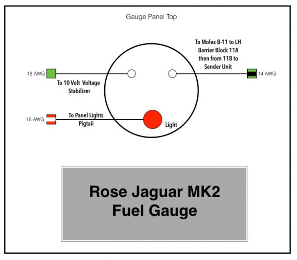
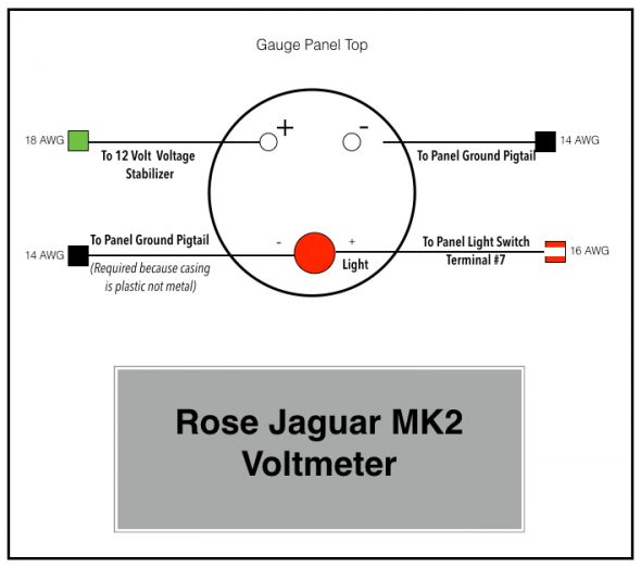
There are four gauges located in the central instrument panel assembly: from left to right when looking at the face of the panel, the water temperature gauge, the oil pressure gauge, the fuel gauge, and the voltmeter which is substituted for the original ammeter. As with the switches, the gauges are explained more fully in the “Gauges, Instruments and Switches” post.
The following images depict the wiring for each of the four gauges:

