January 15, 2005
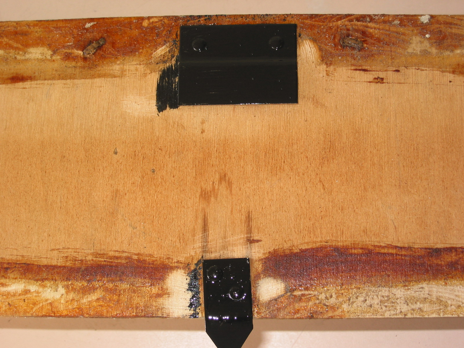
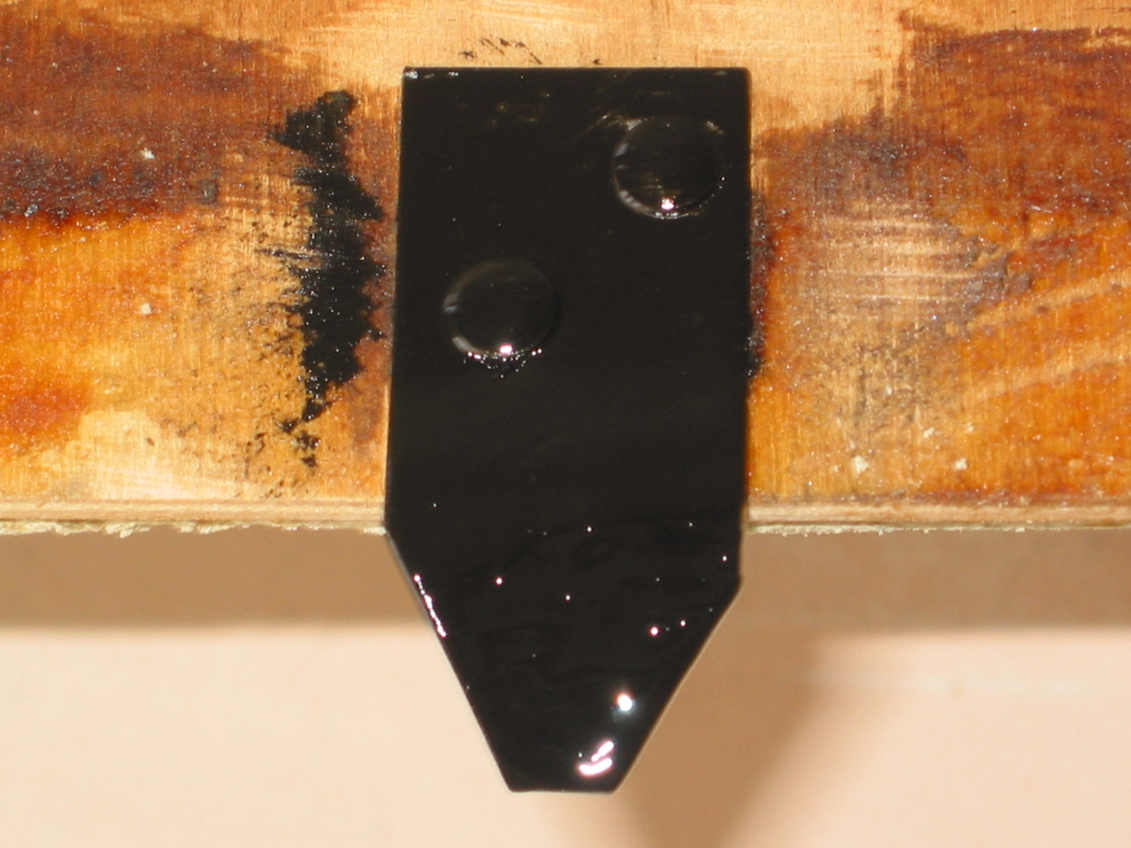
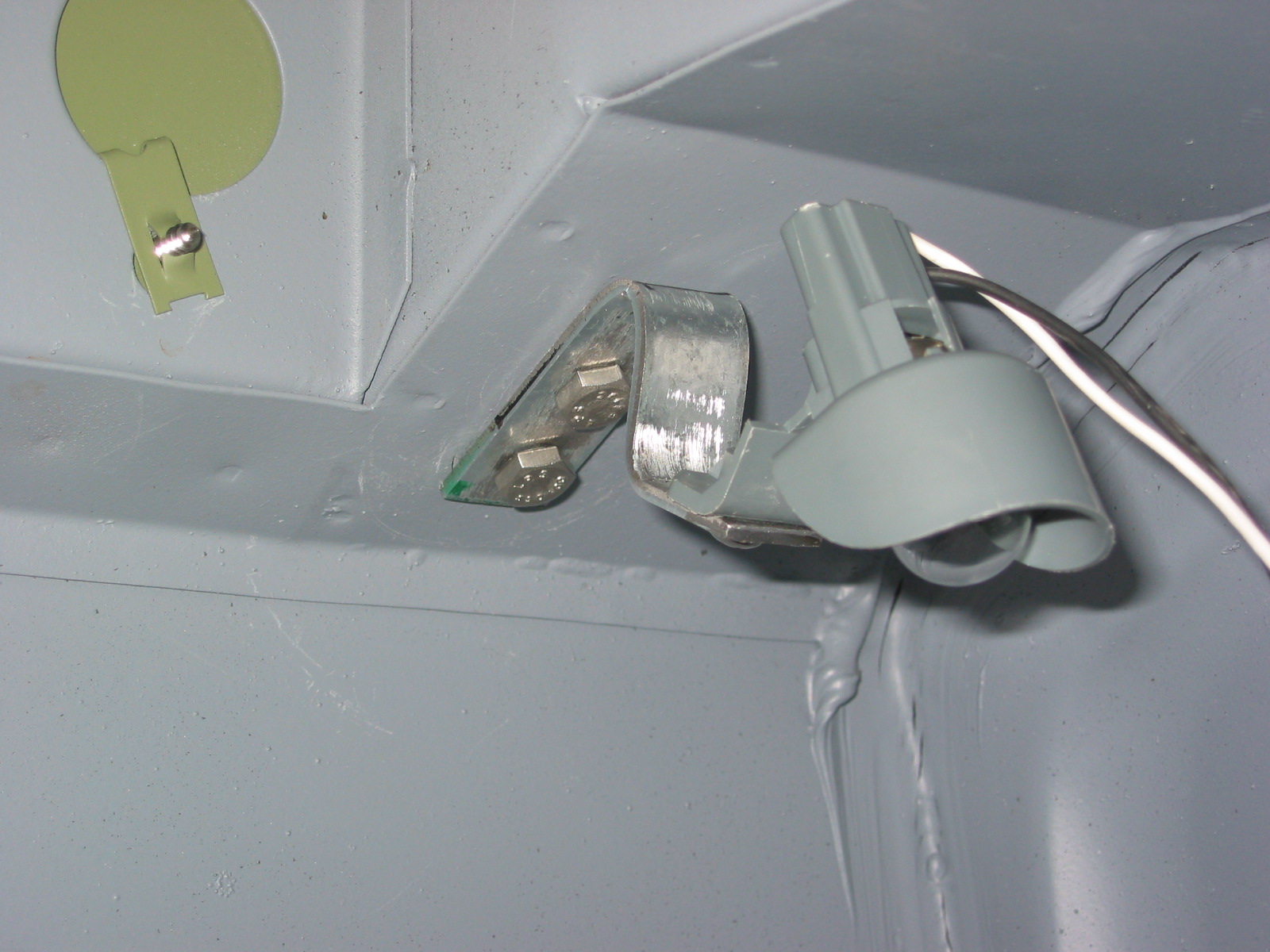
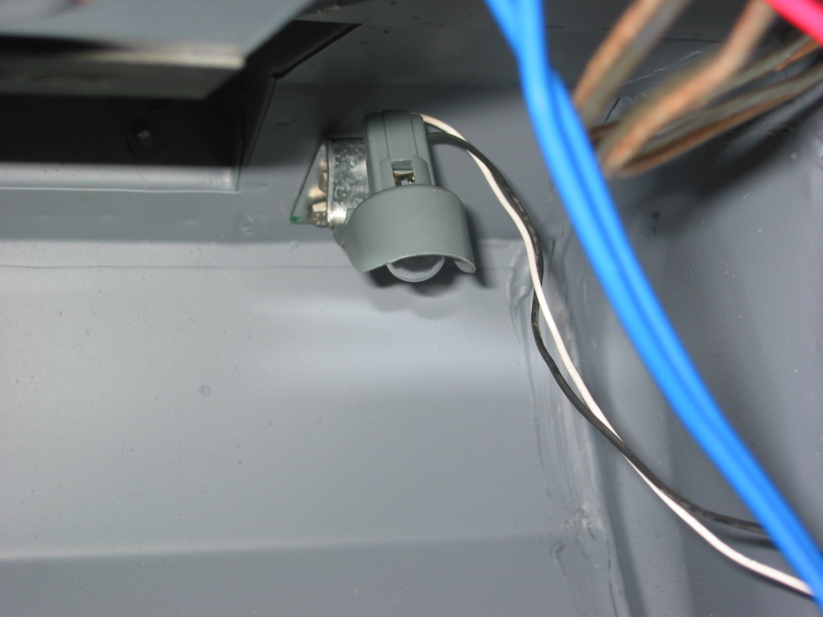
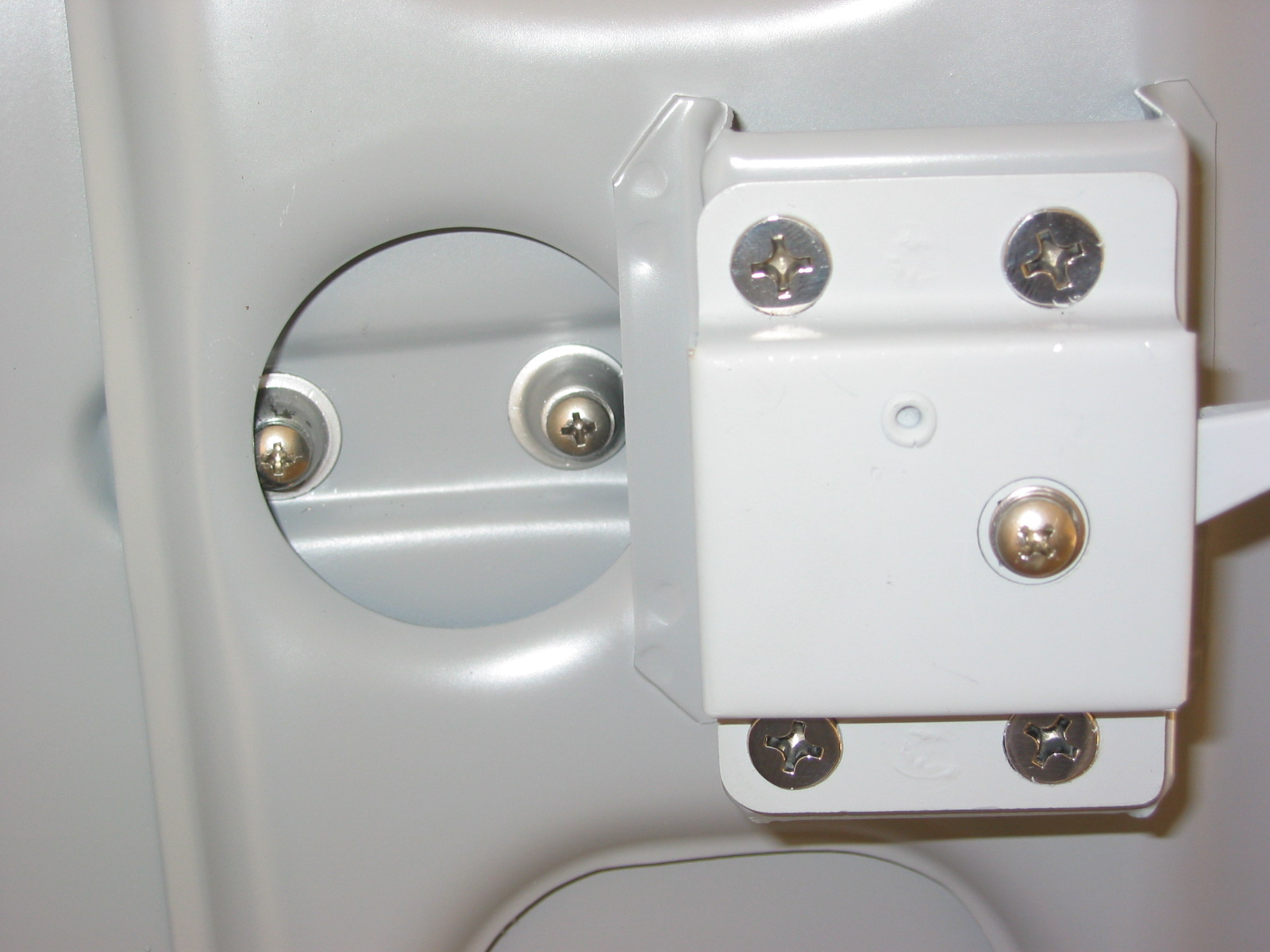
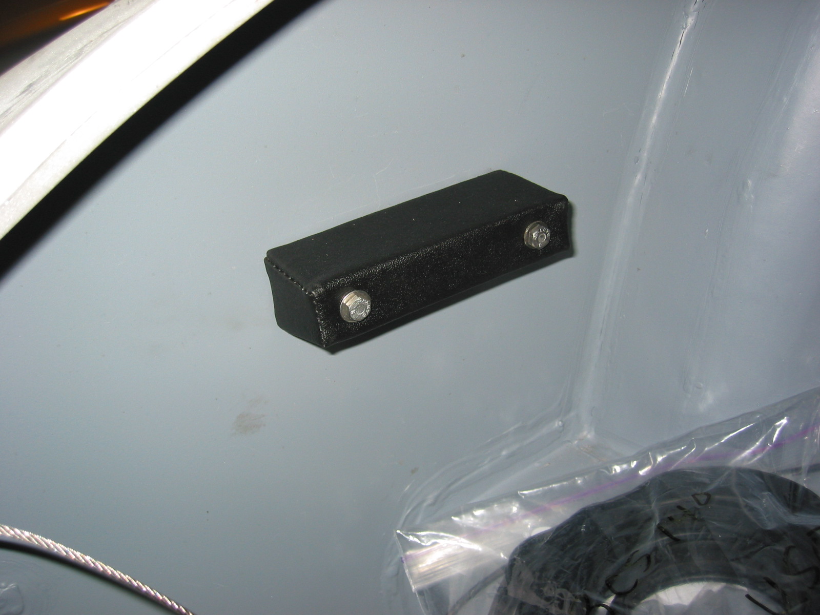
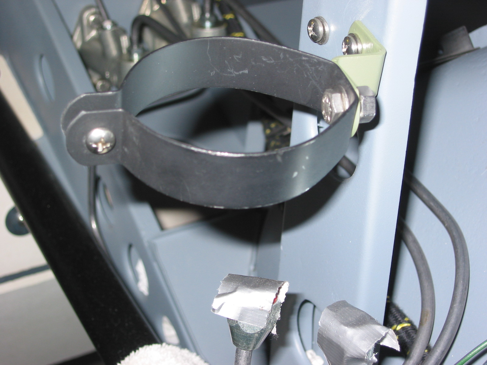
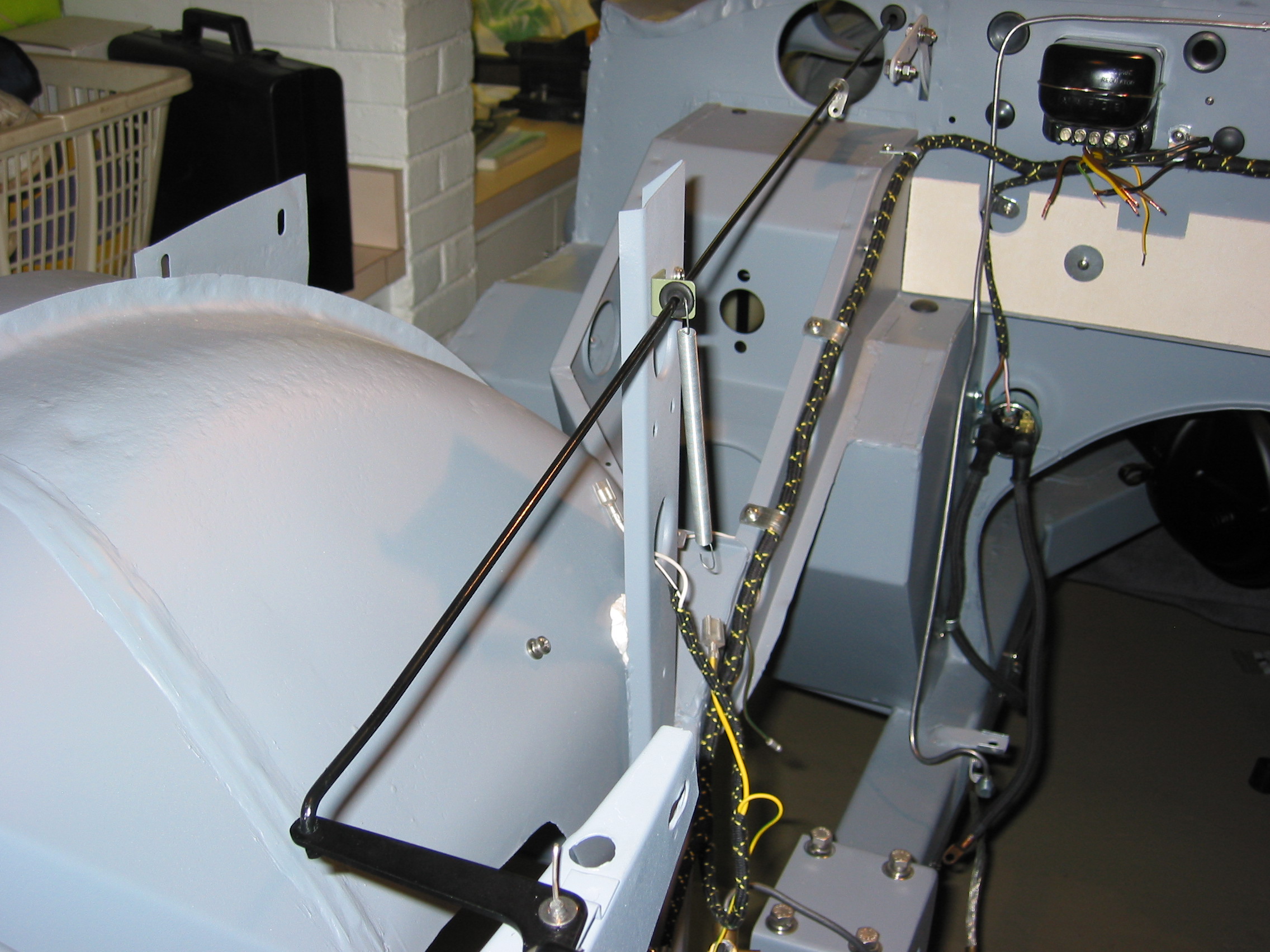
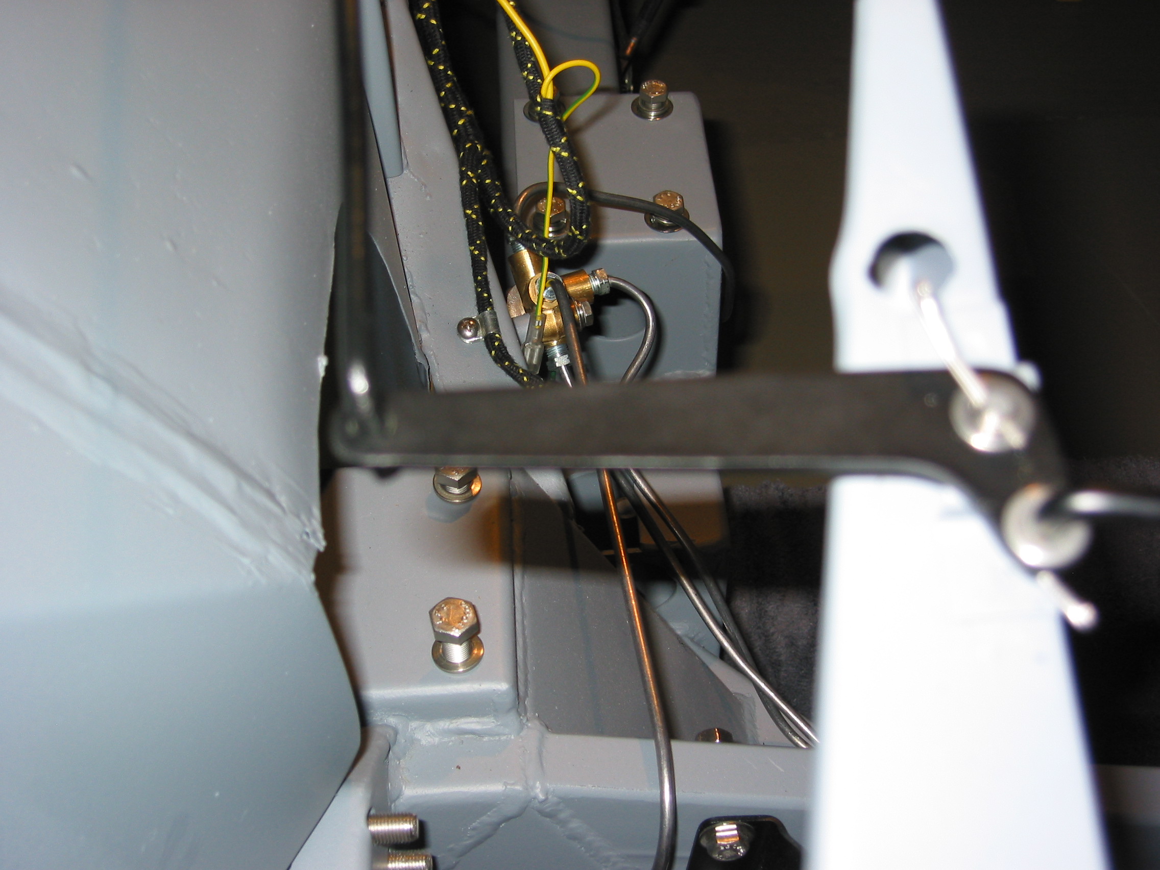
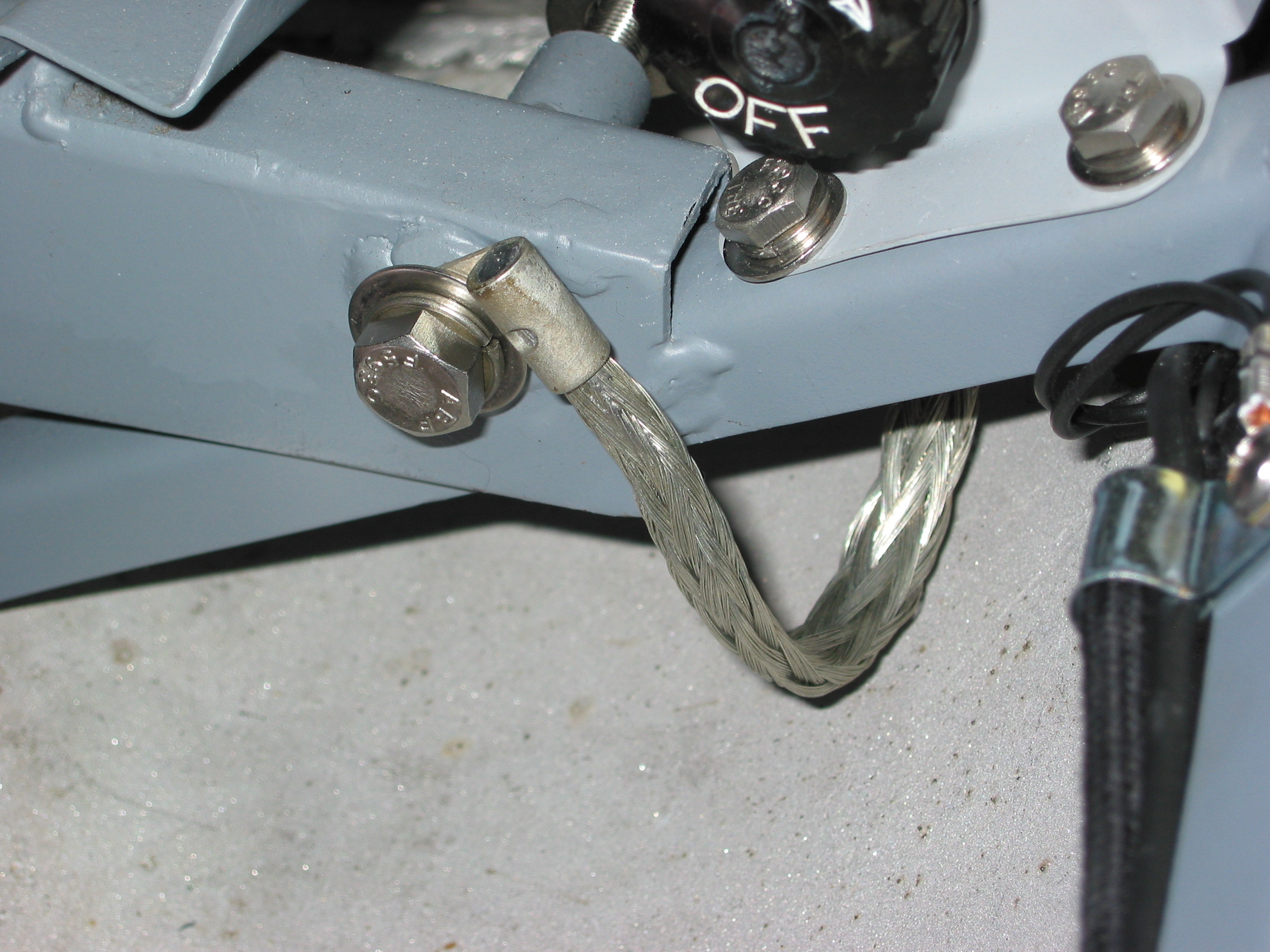
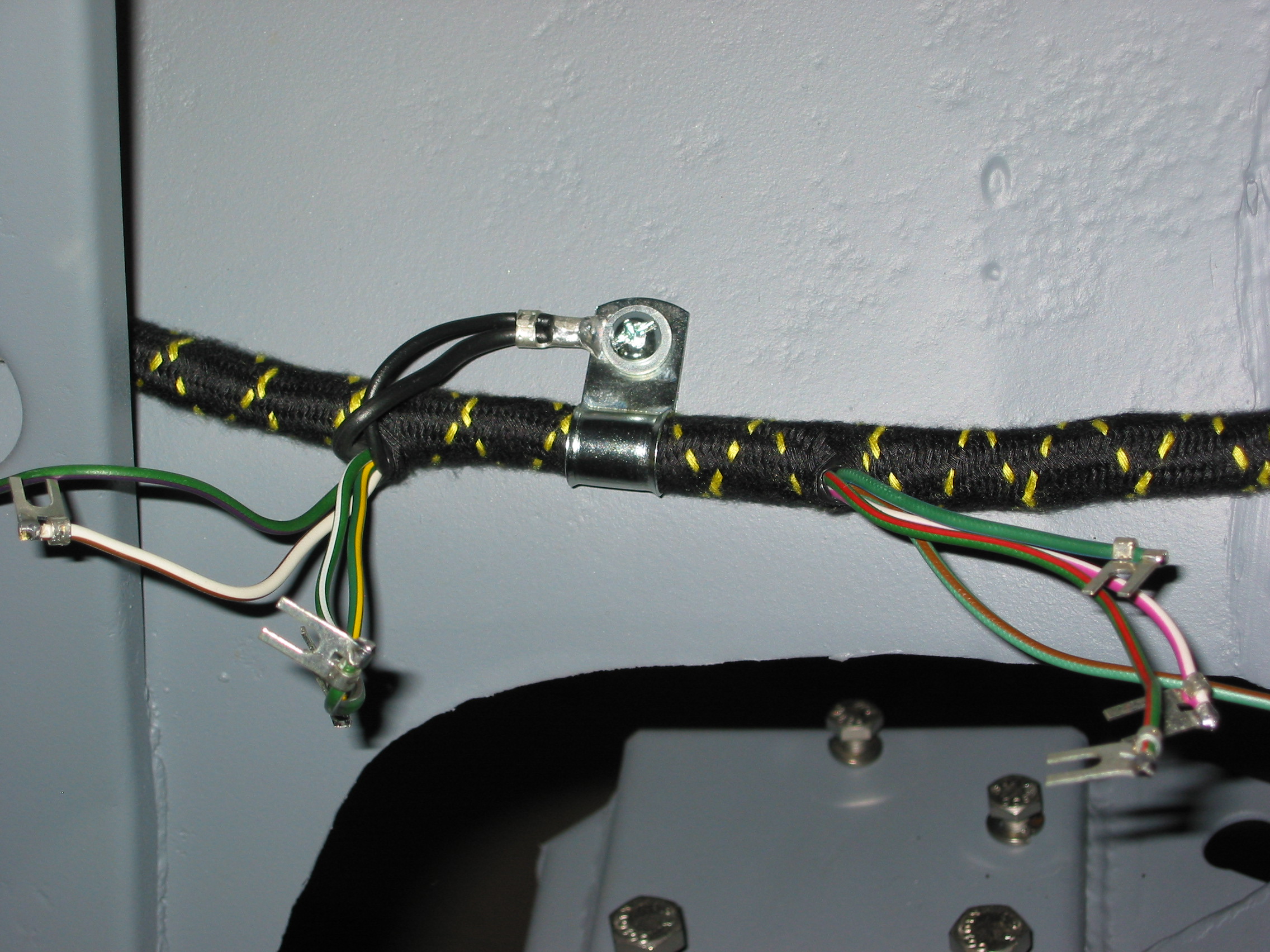
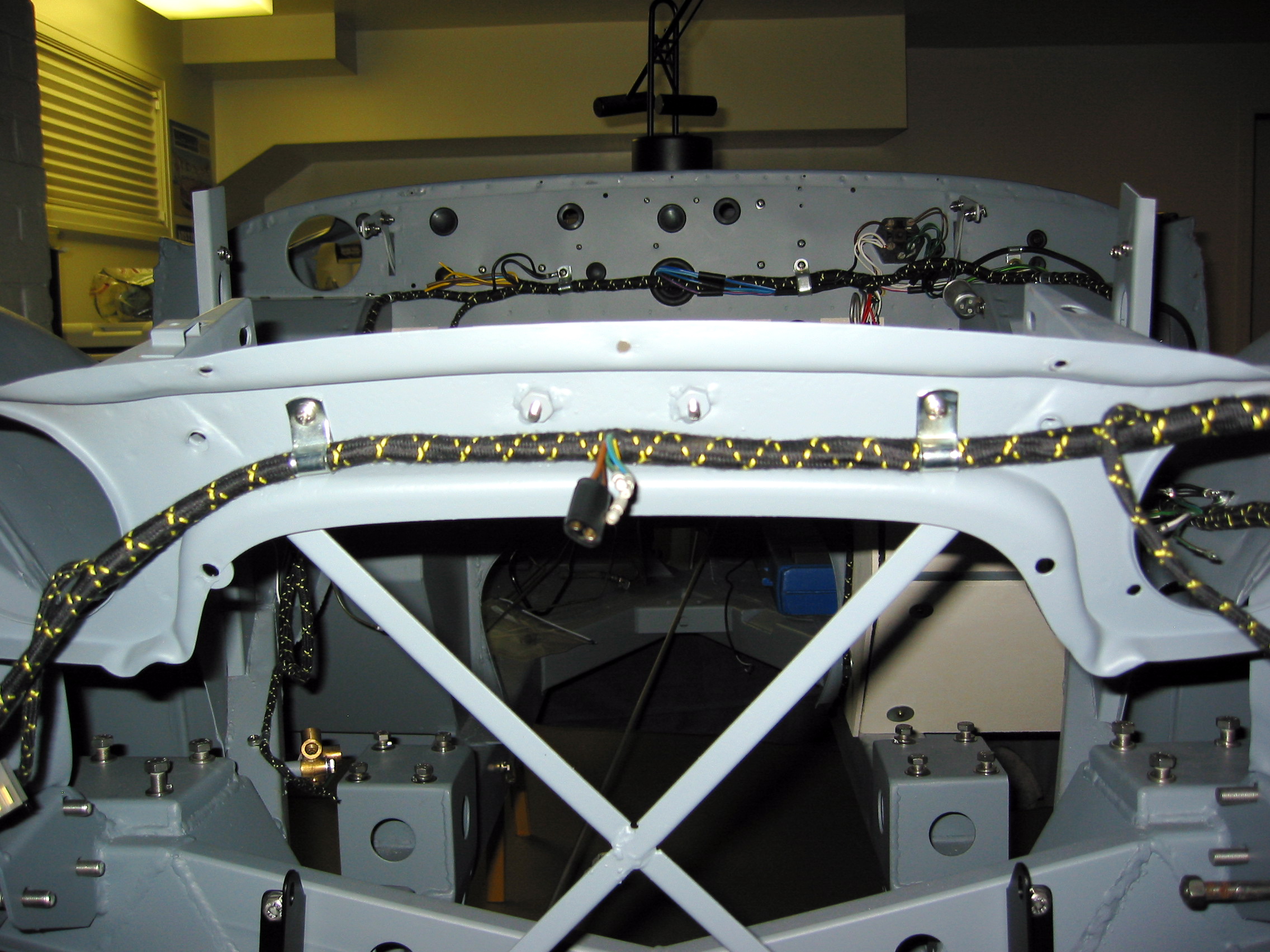
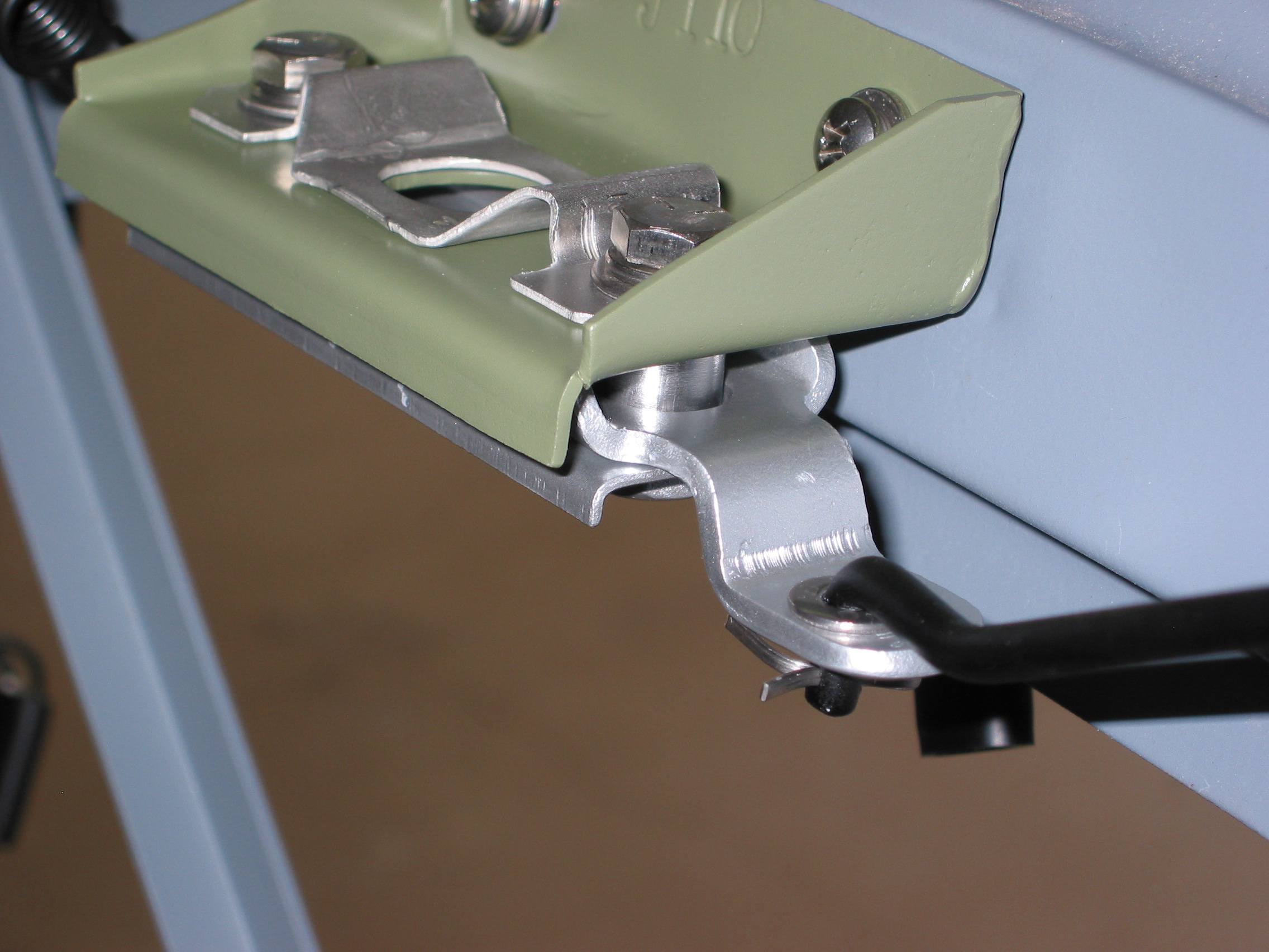
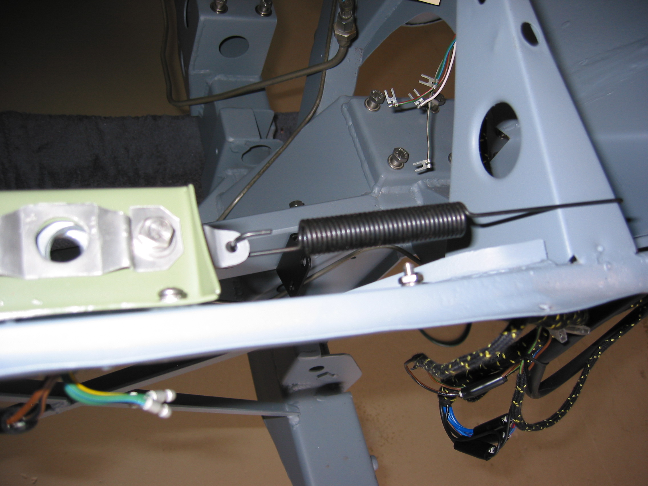
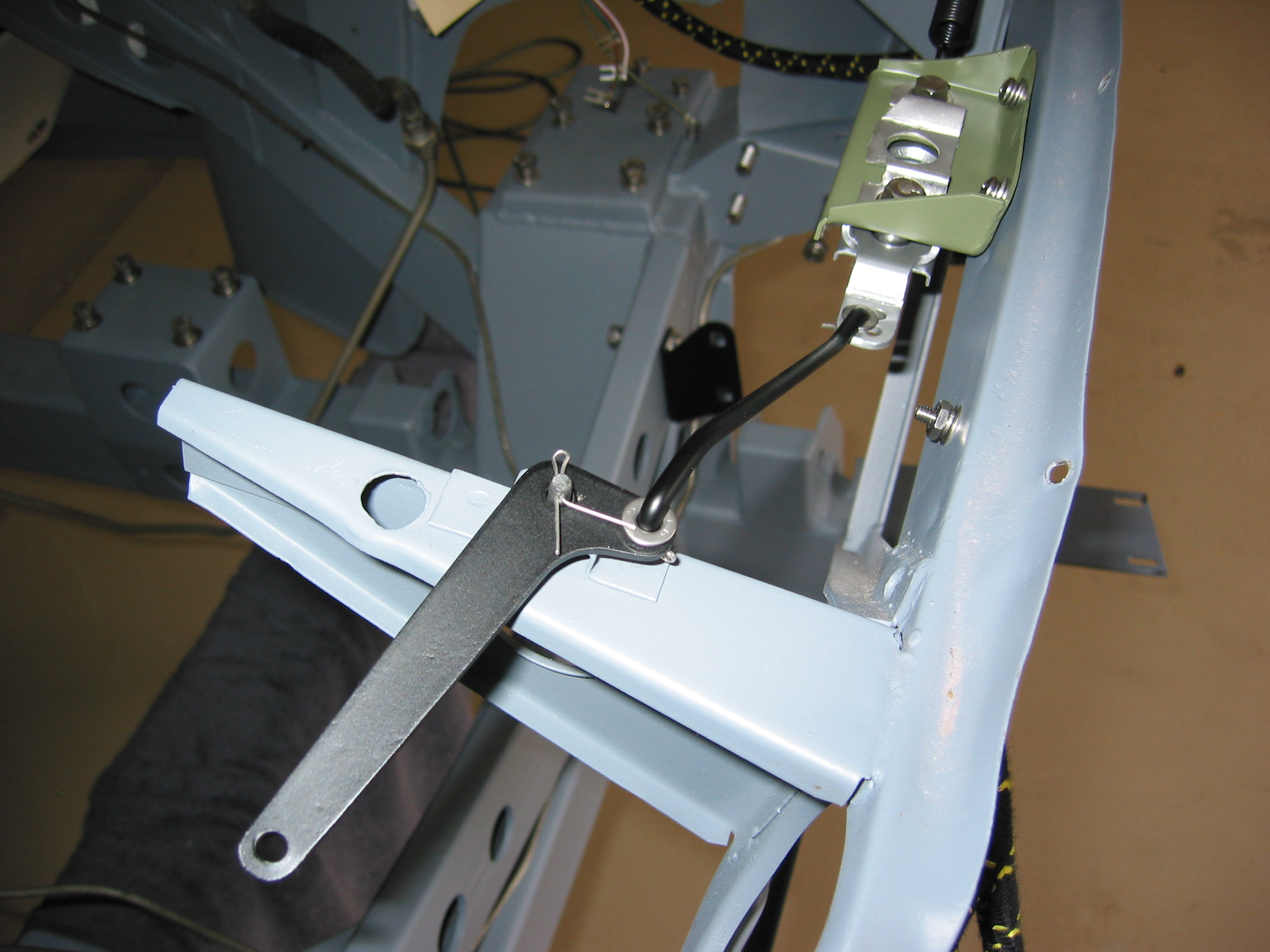
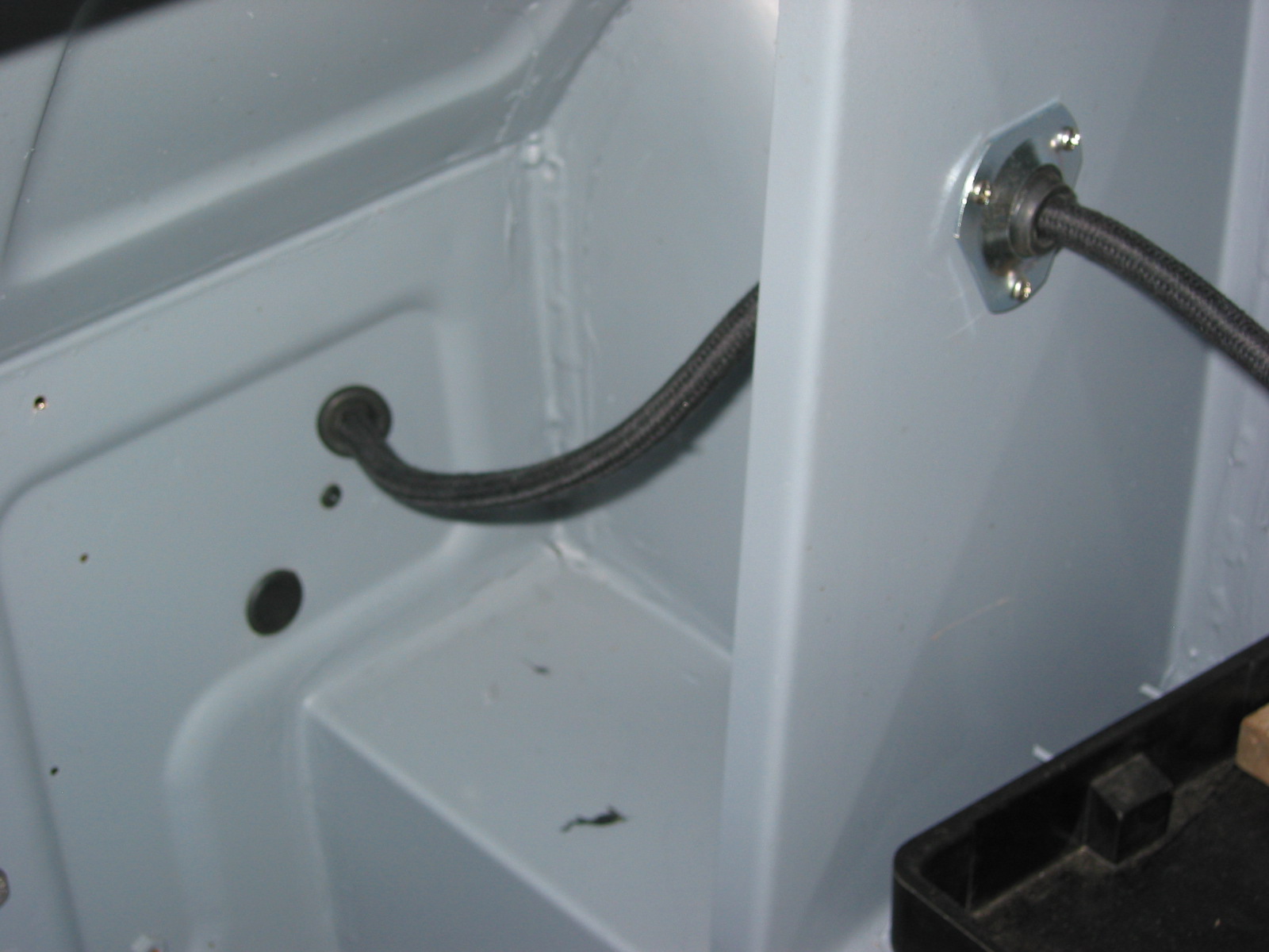
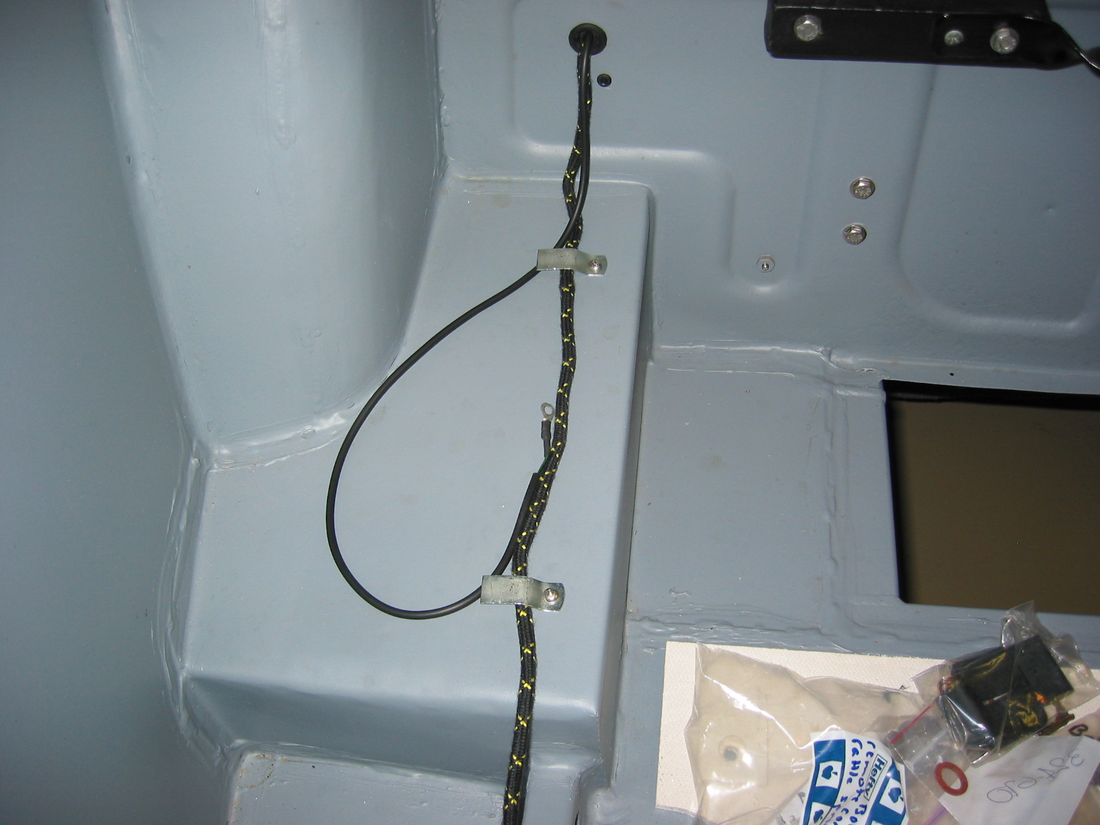
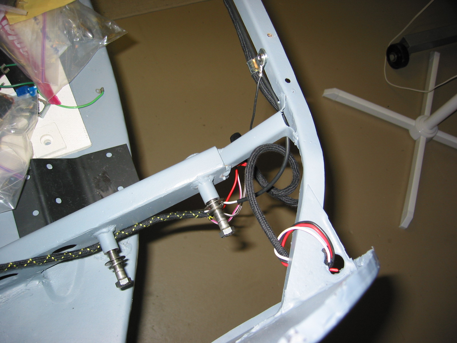
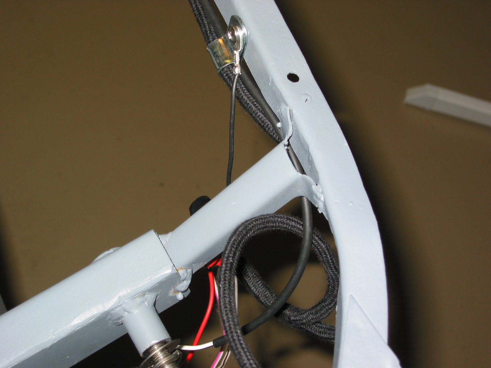
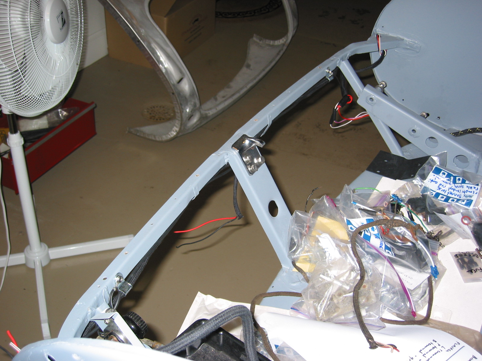
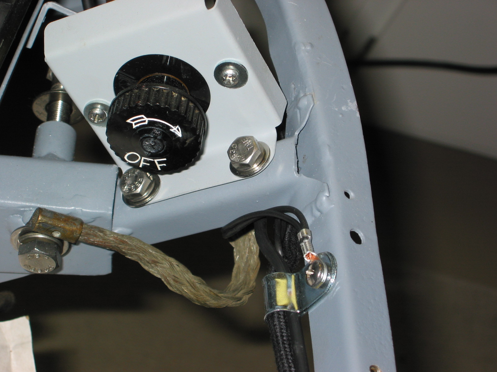
Turn Signal Audible Buzzer – I had used a little buzzer produced by Radio Shack in the Bugeye and decided that I would add one in the Big Healey also. I will just use a little 3M double sided sticker to fasten it to the fascia support bar since it is so light. That will get it as close as possible to the driver. The buzzer has 2 wires. Red wire is joined to a pink wire that is routed through the firewall and connected to the center post on the flasher canister. The black wire is grounded by connecting it to the fascia support bar screw and nut.
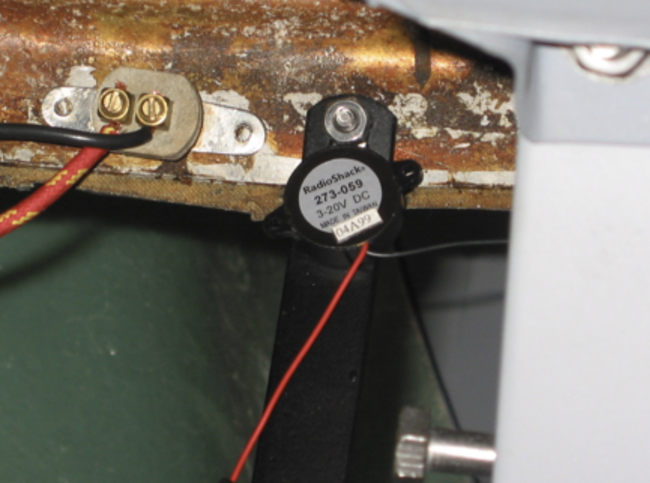
Buzzer Mounting
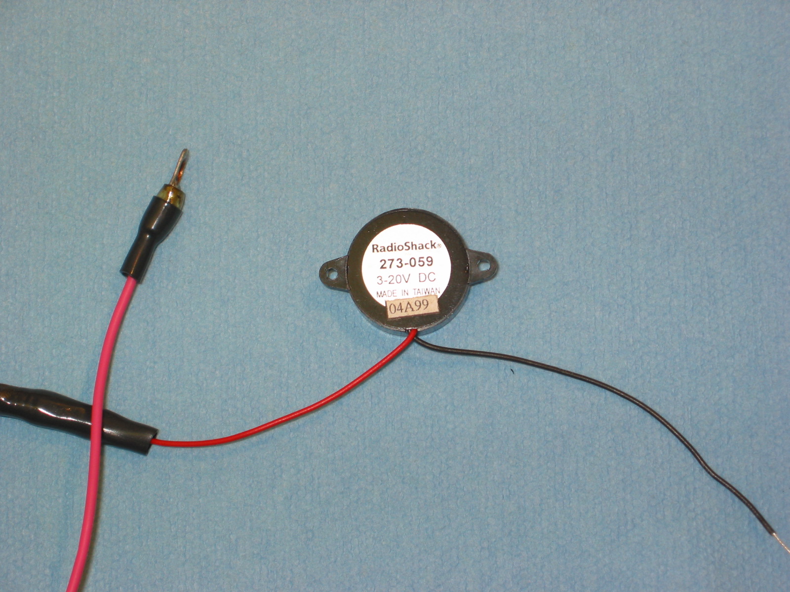
Signal buzzer radio shack
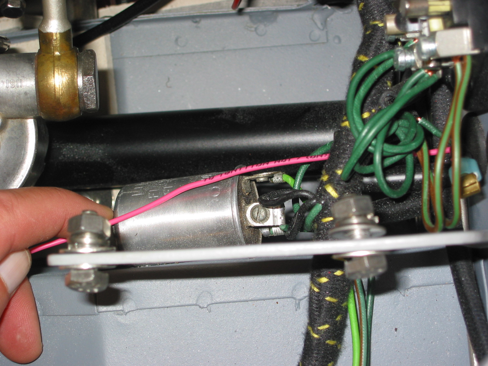
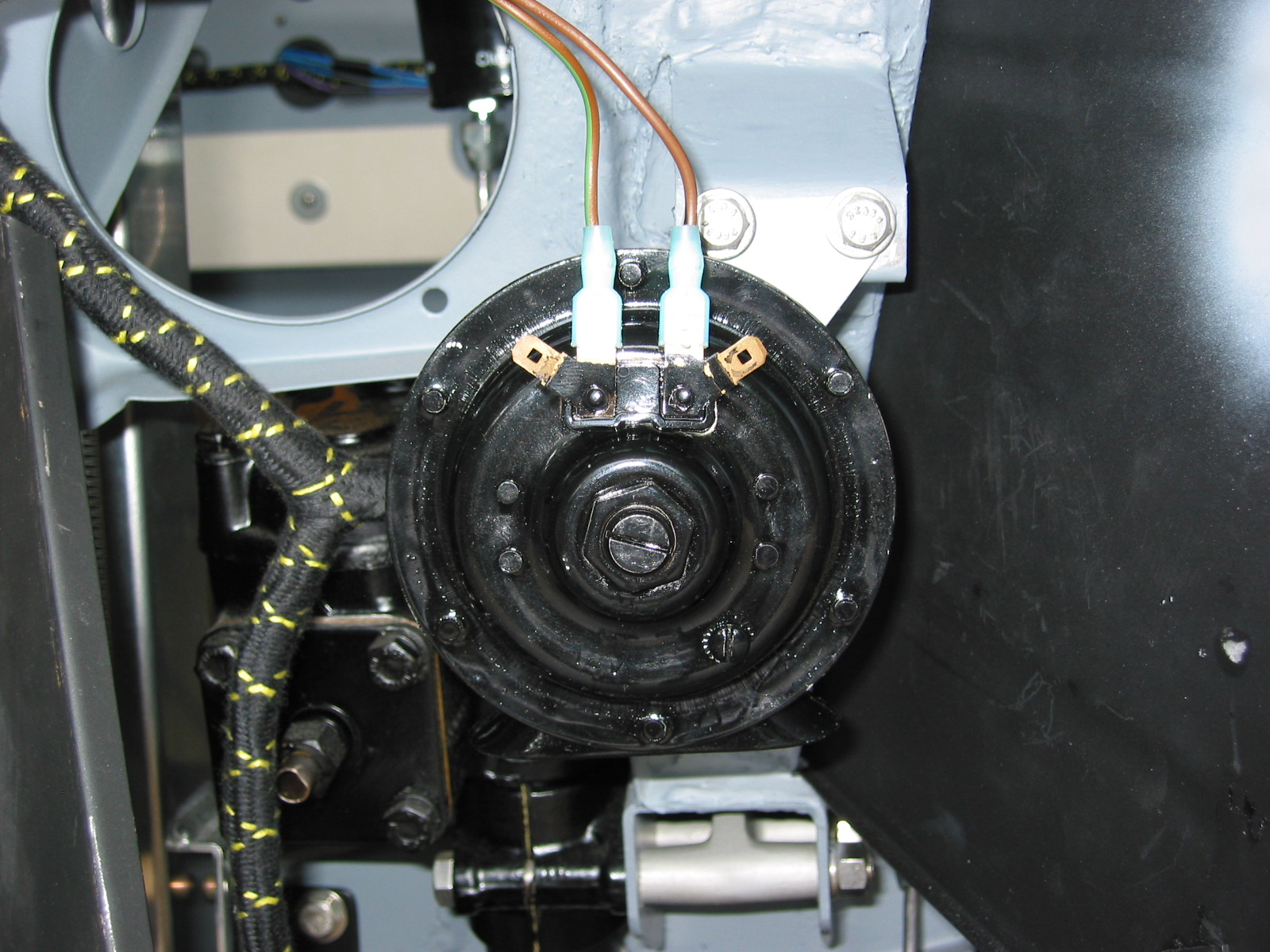
Signal buzzer connection
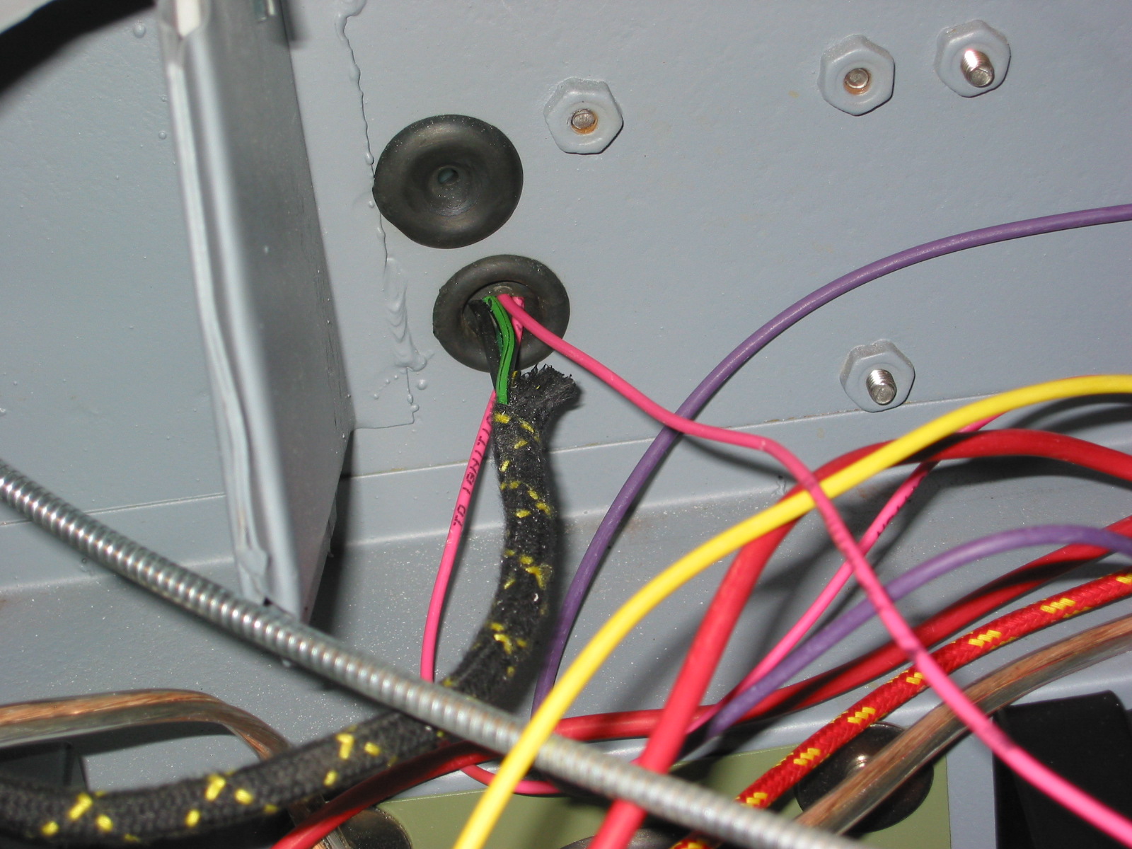
Signal buzzer wiring
January 22, 2005
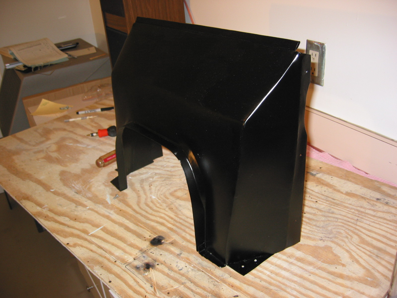
Other Accommodations to Modern Technology
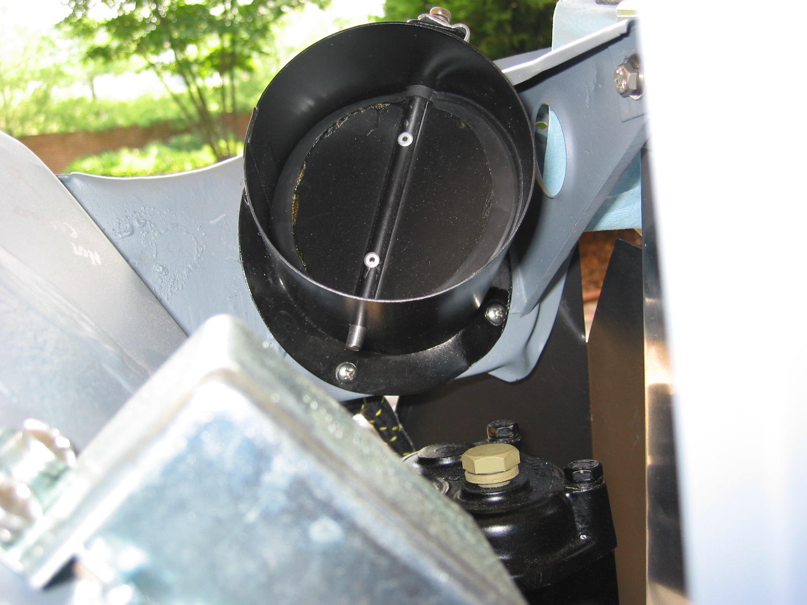
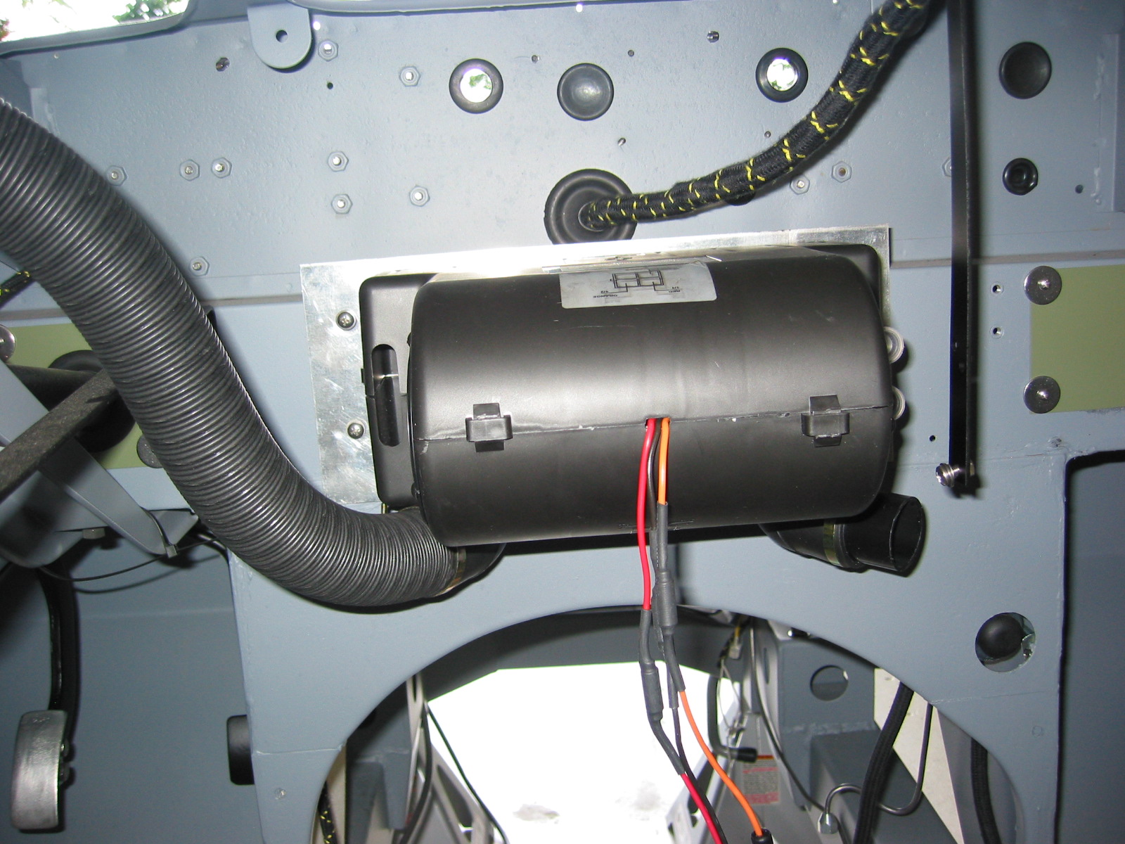
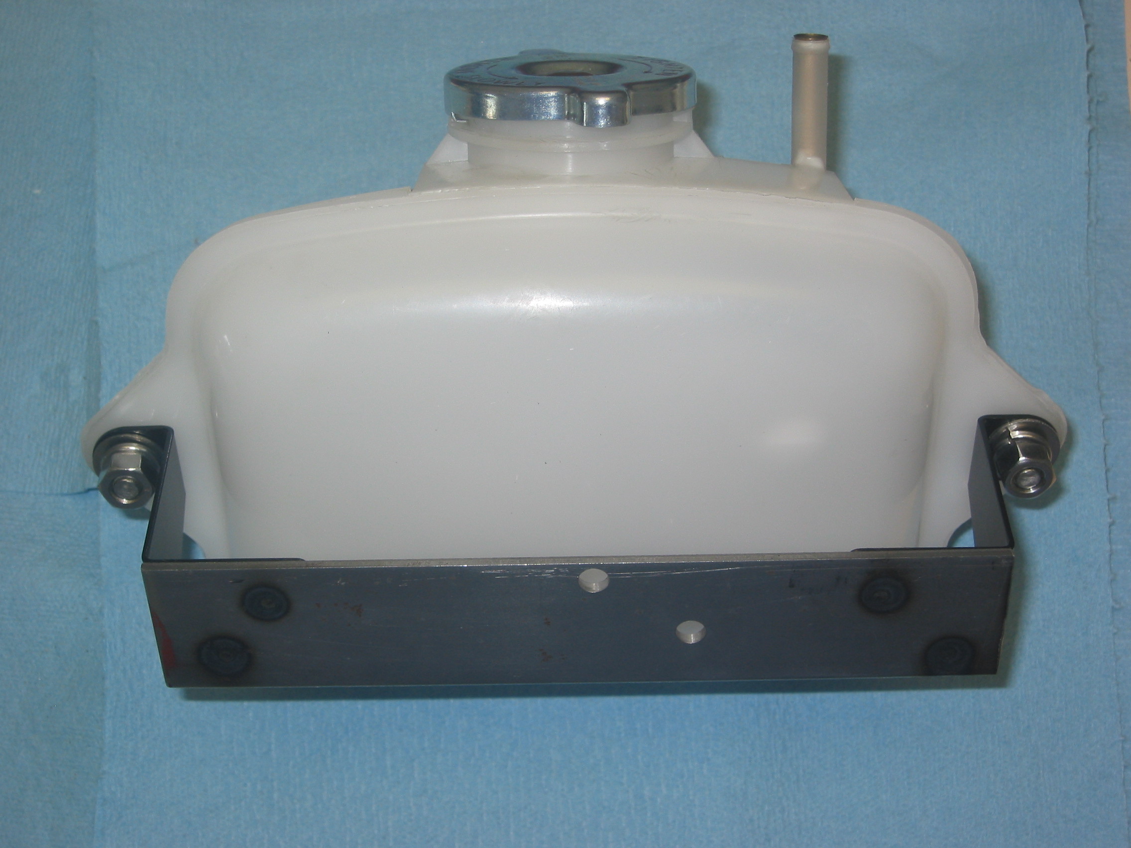
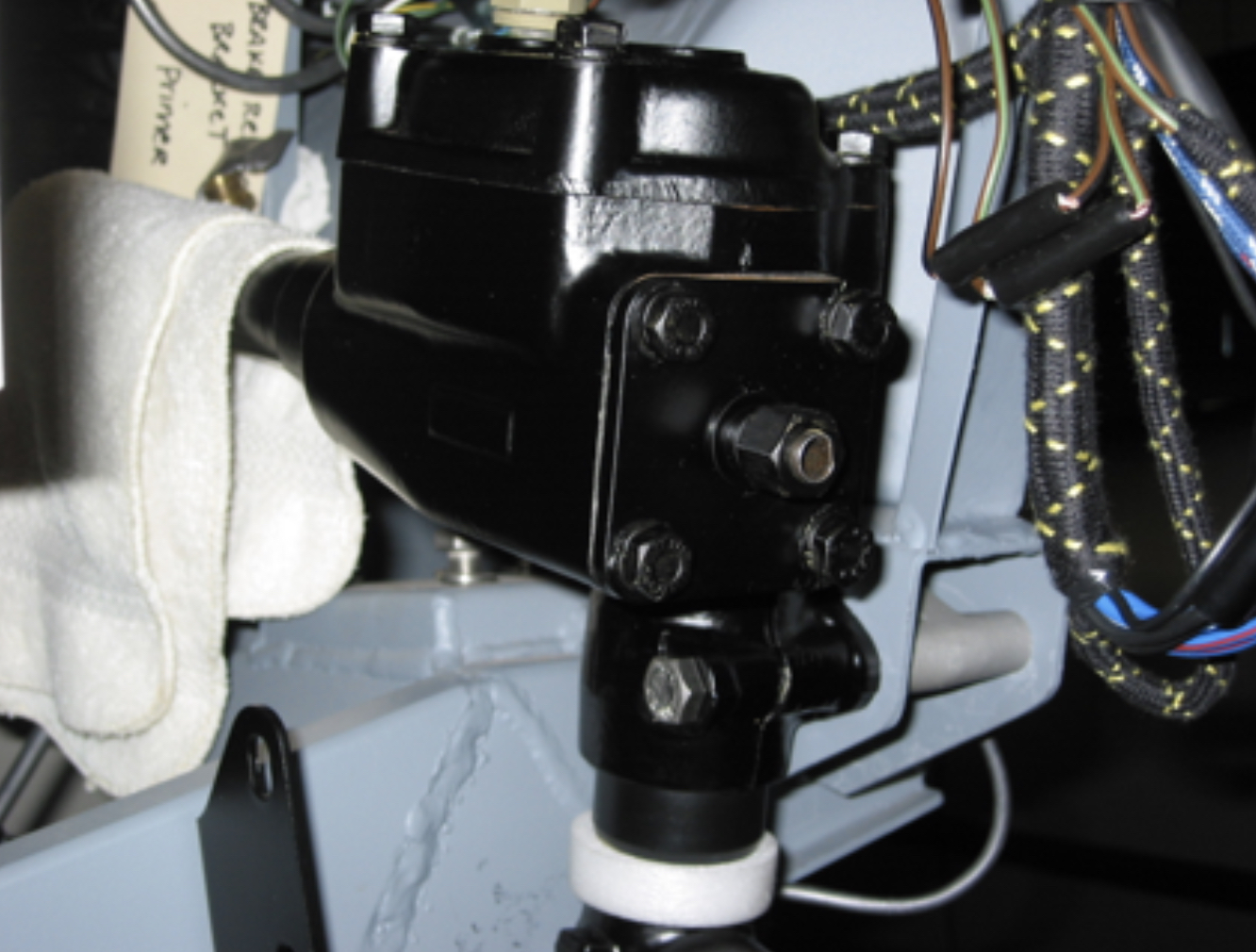
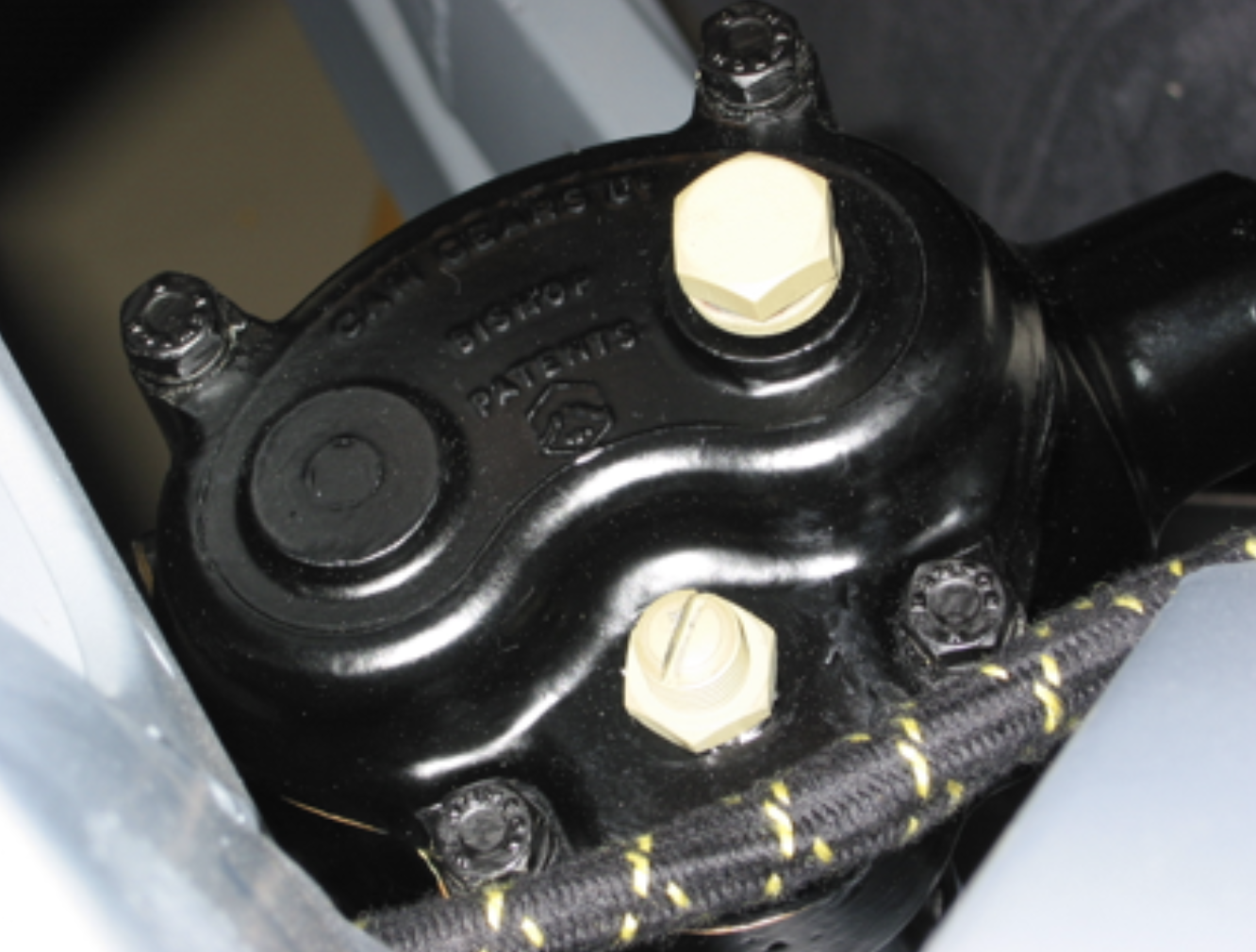
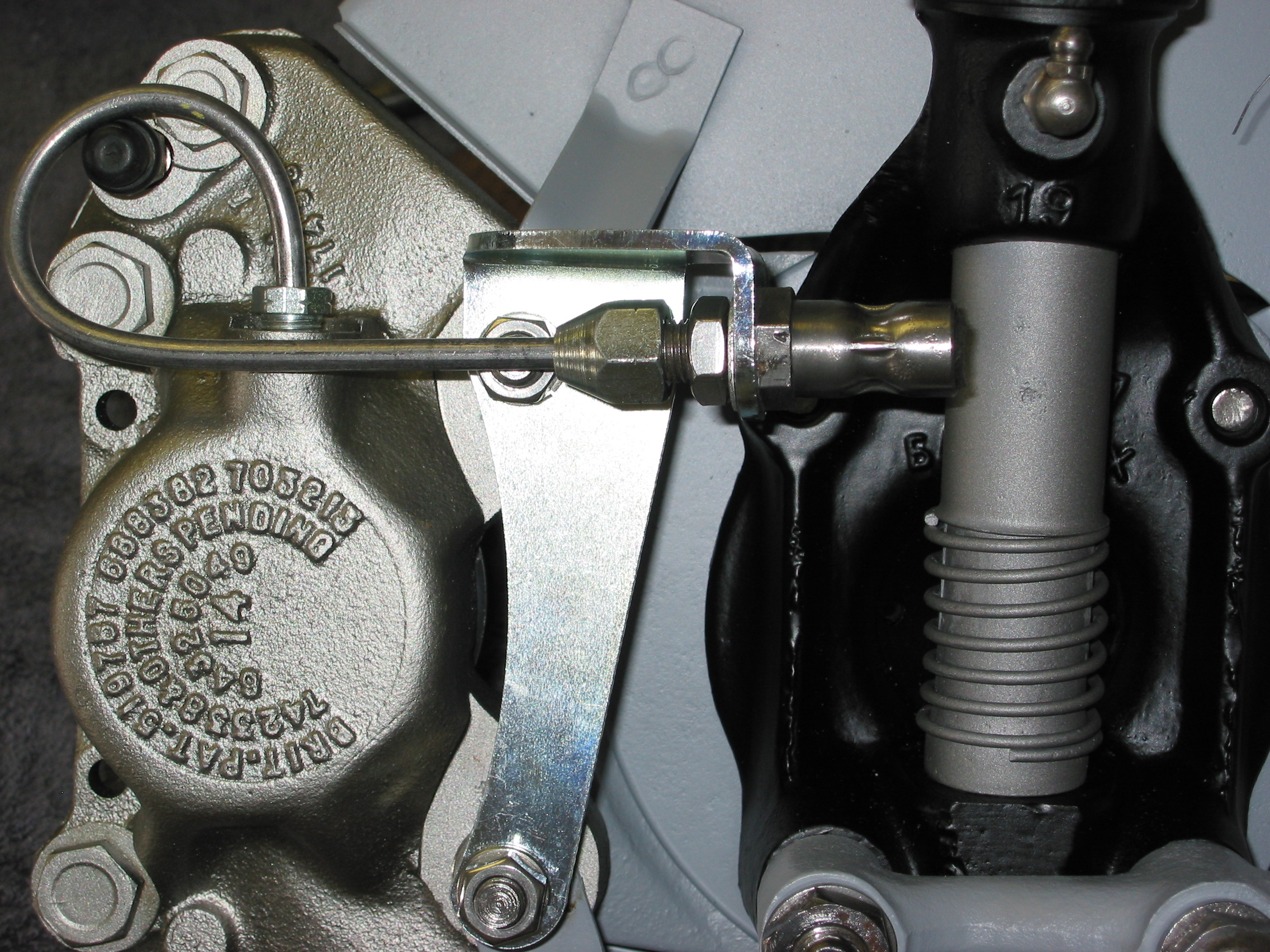
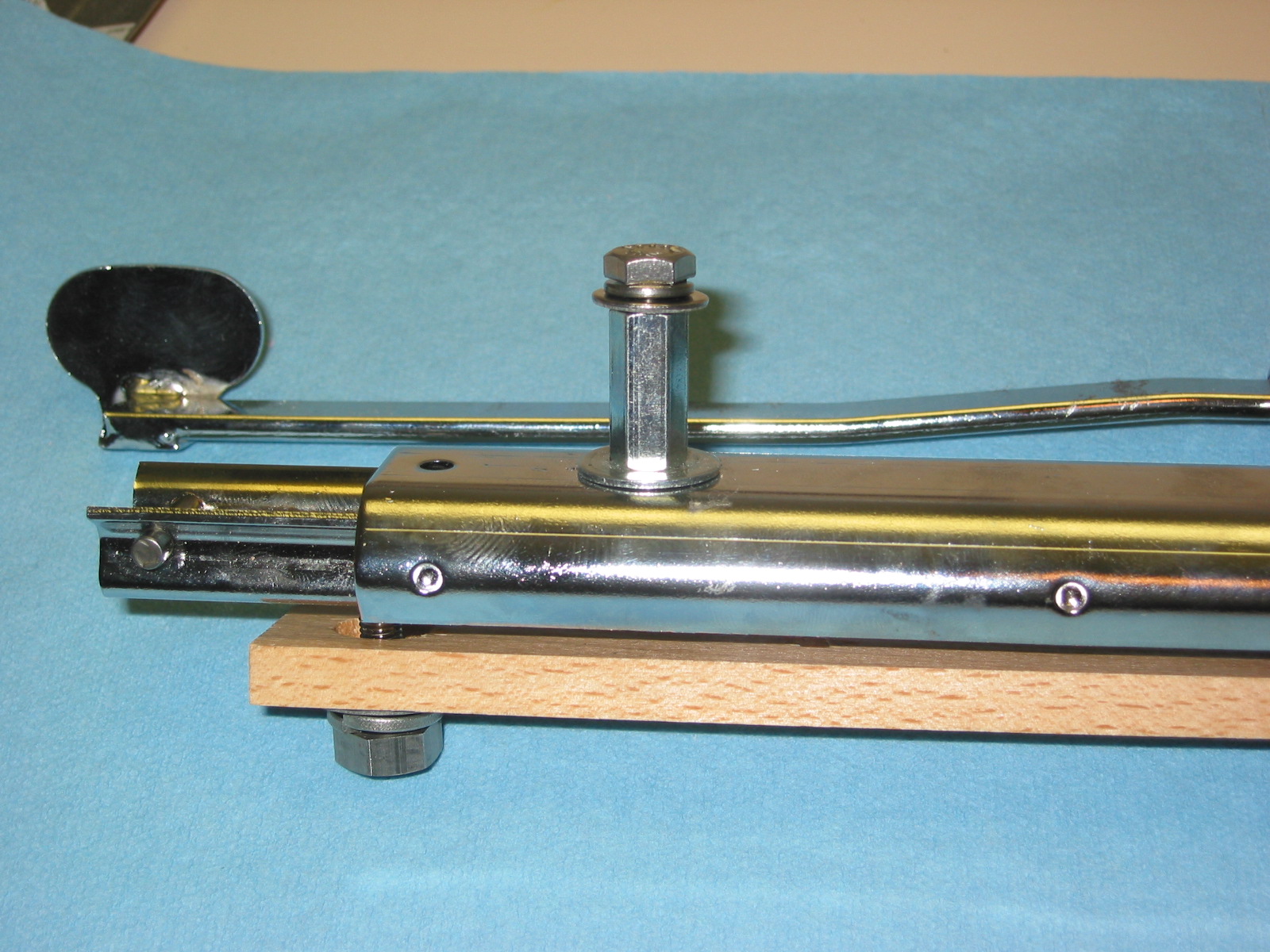
Electric windscreen washer – I read a technical article by Stu Brennan, an owner of a Sunbeam Tiger, who had converted his hand activated pump windscreen washer to an electric washer. I liked the idea because he put the electric switch in the aluminum pump canister thereby eliminating the need to install an additional switch somewhere. Since the washer in the Tiger is the same as the one in the Healey I decided to give it a try.
Two items needed to be purchased for the conversion. As Stu did, I used an electric pump purchased at an AutoZone, part number 9-300 from TAAP Corp. I purchased a Home Depot switch, Gardner-Bender, Push Button, GSW-22, SPST always-off.
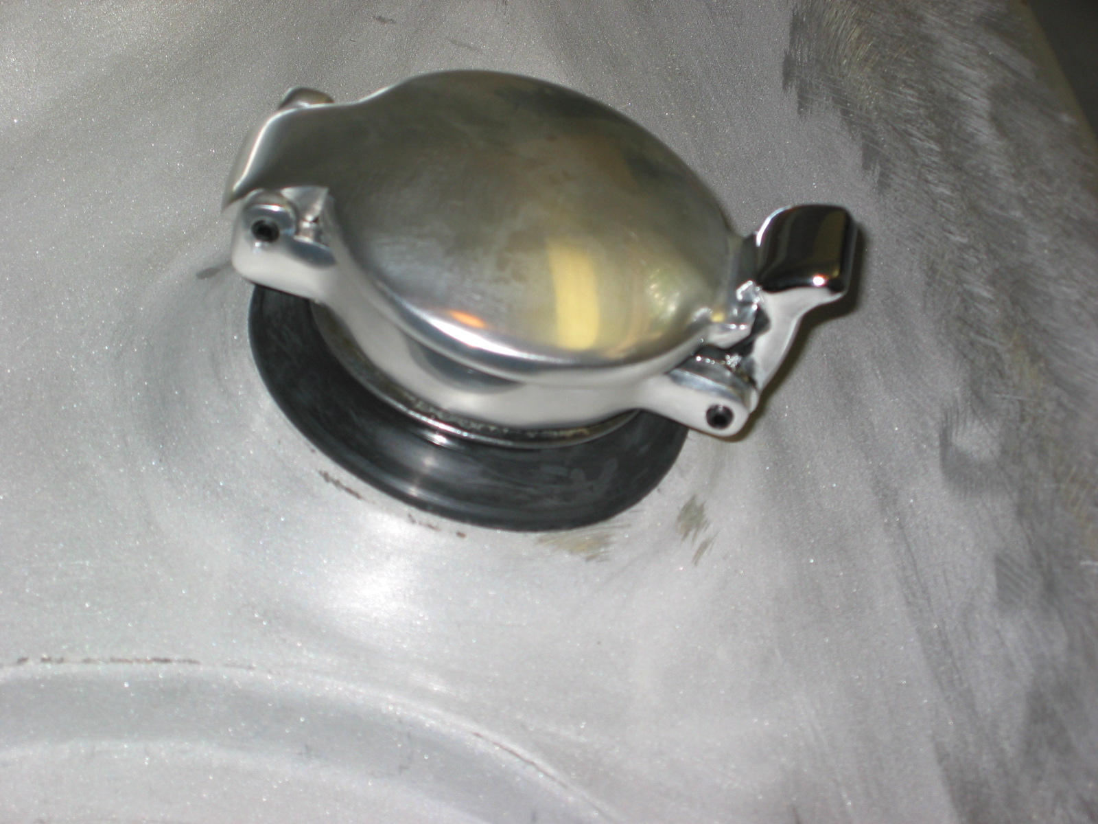
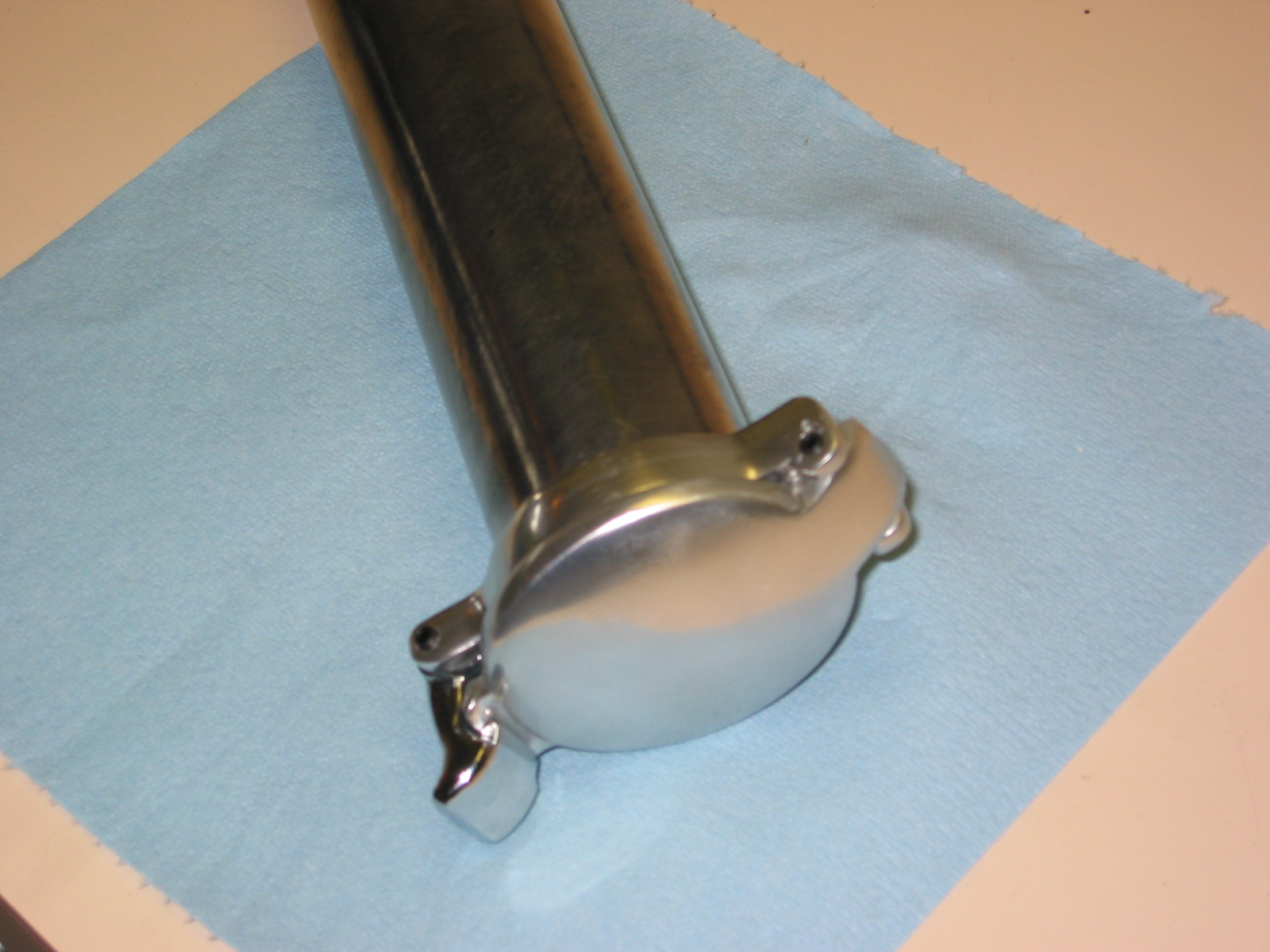
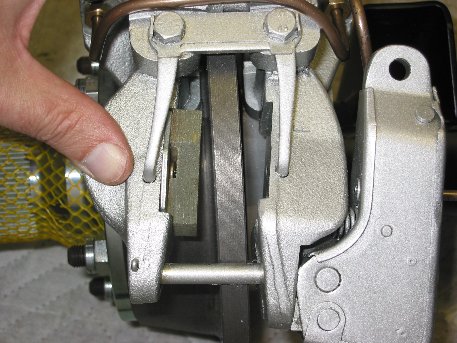
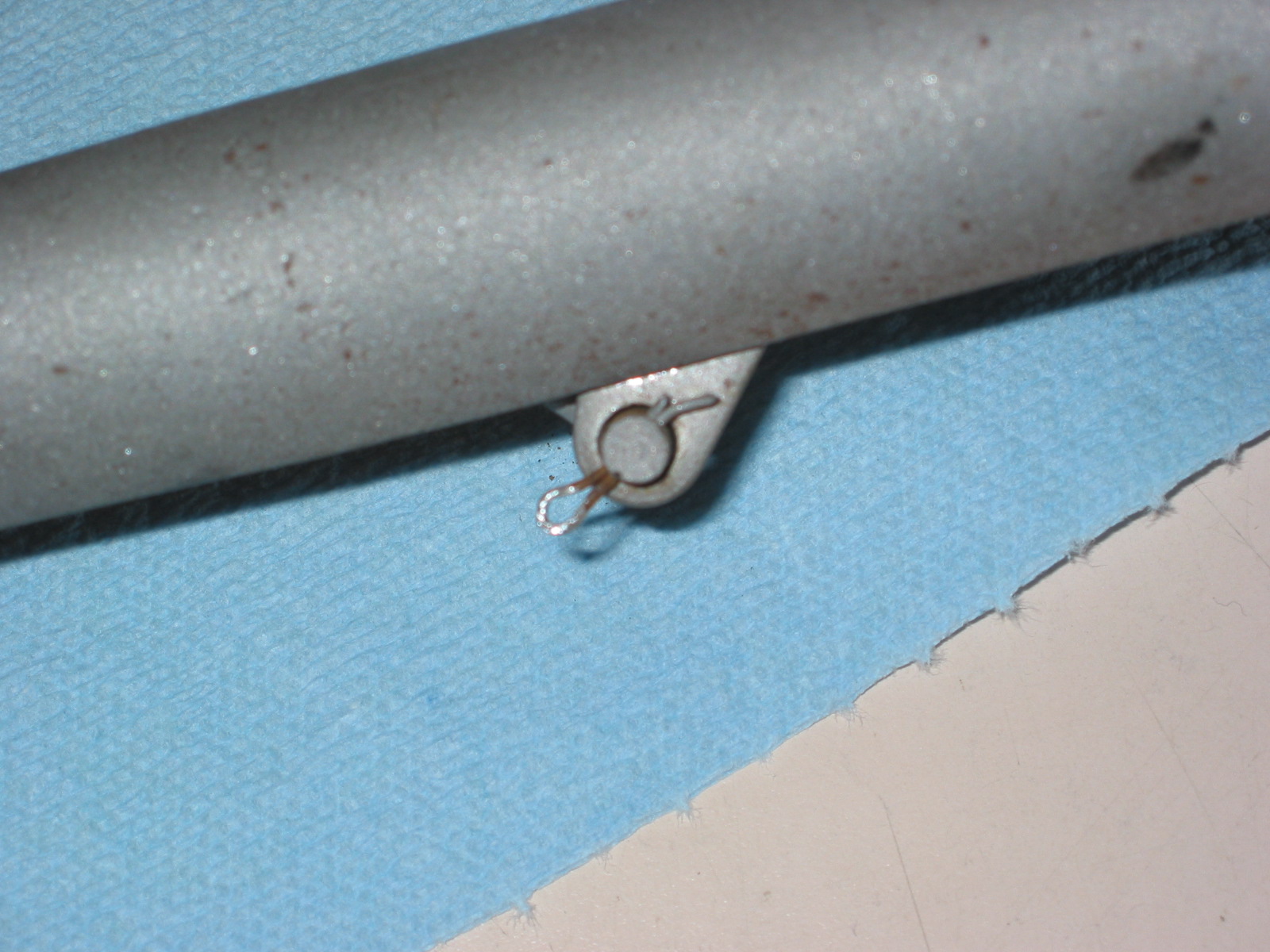
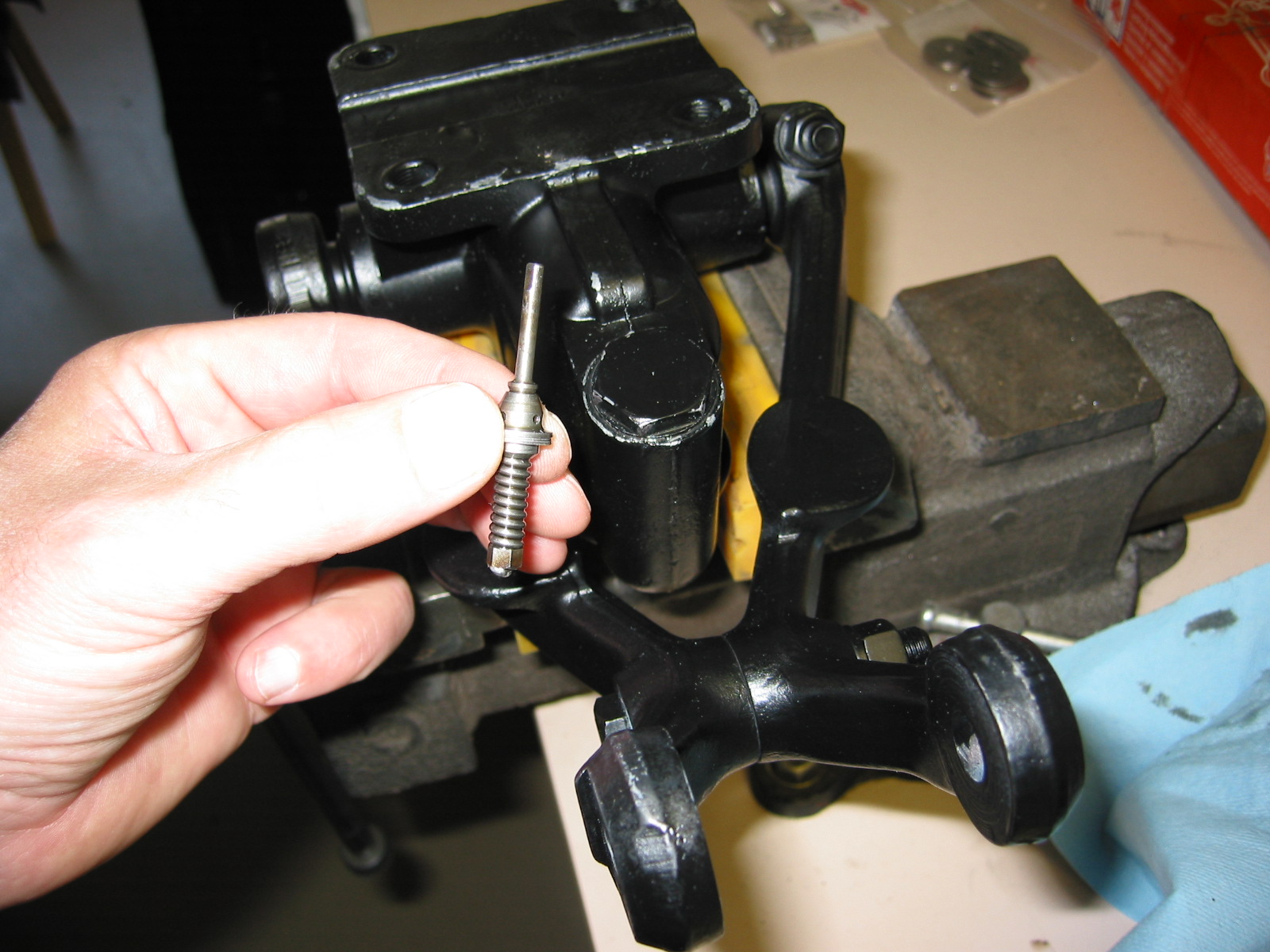
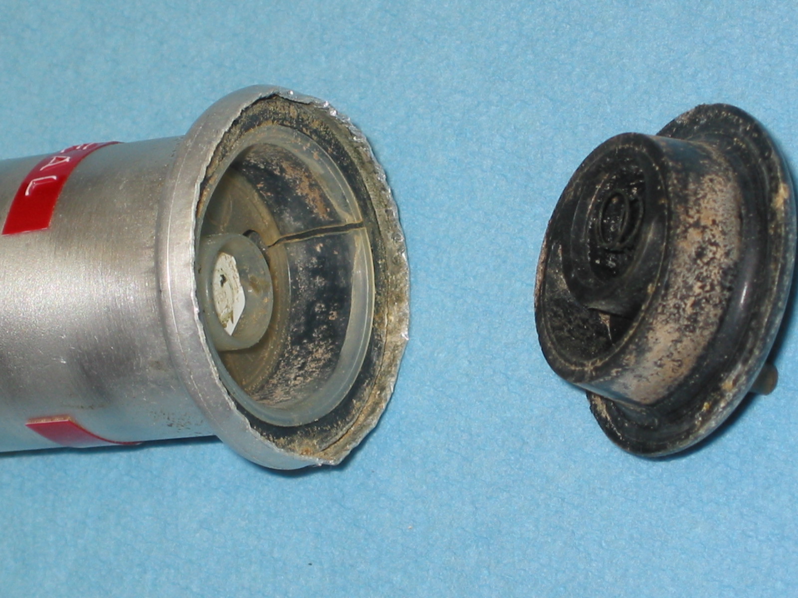
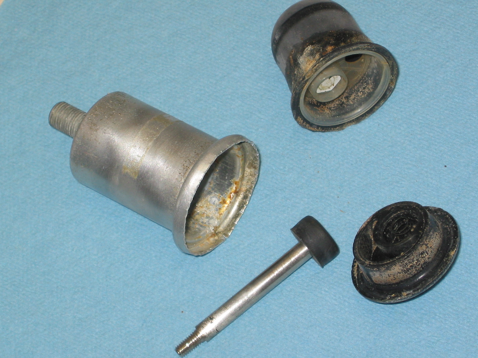
The old pump was easily disassembled by un-crimping the lip from around the plastic bottom. The metal is relatively soft, so it unfolds easily. The bottom and the old rubber bellows came right out, leaving only the plunger within the shell of the pump.
Windscreen washer pump 2
Windscreen washer pump 3
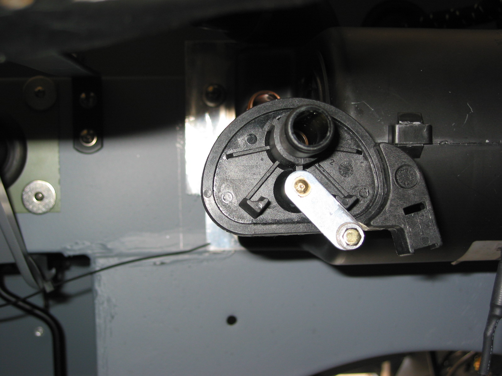
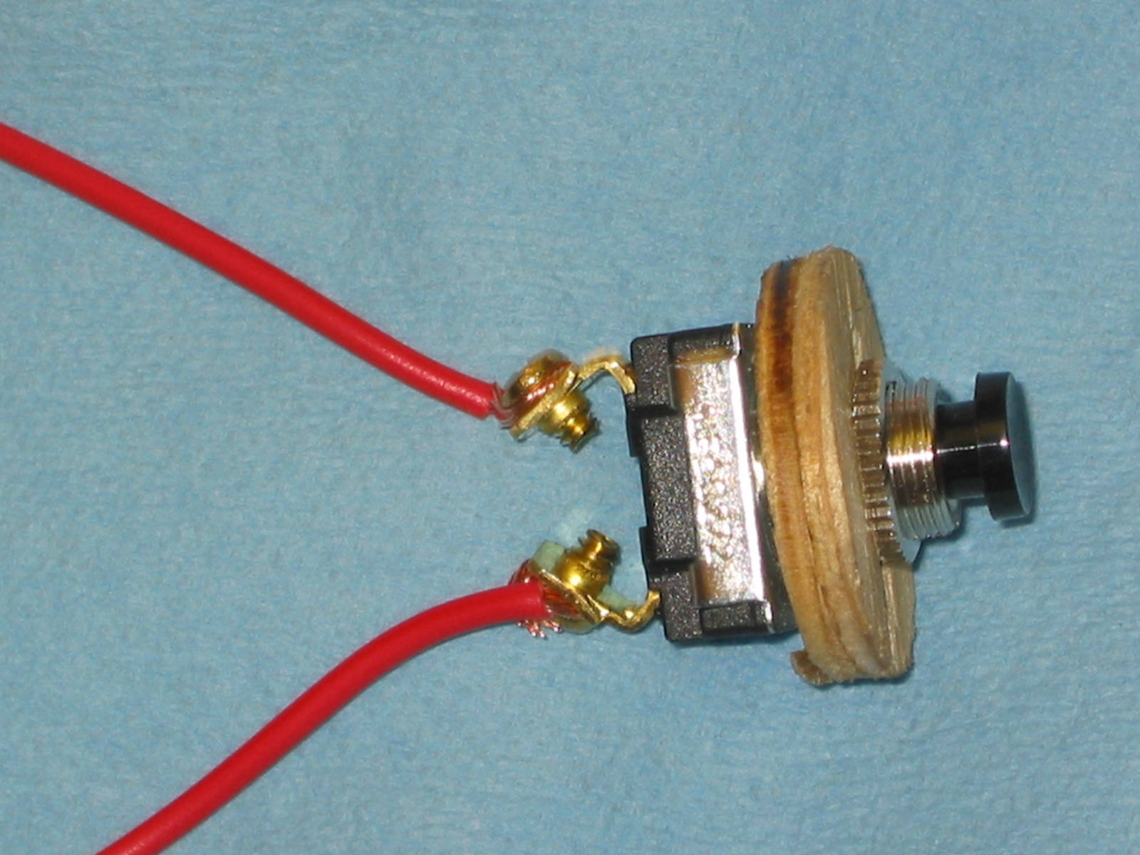
To provide stability for the switch in the canister and to use as a spacer I cut a circle washer of 1/4” wide plywood that fit tightly in the canister and placed it on the switch secured with double nuts.
Windscreen washer pump 4
To provide enough depth for the switch in the canister I cut a slot in the plastic face plate. The slot also provided space for the switch wires to exit the canister.

Windscreen washer pump 5
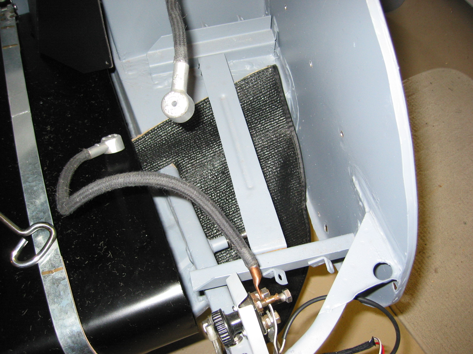
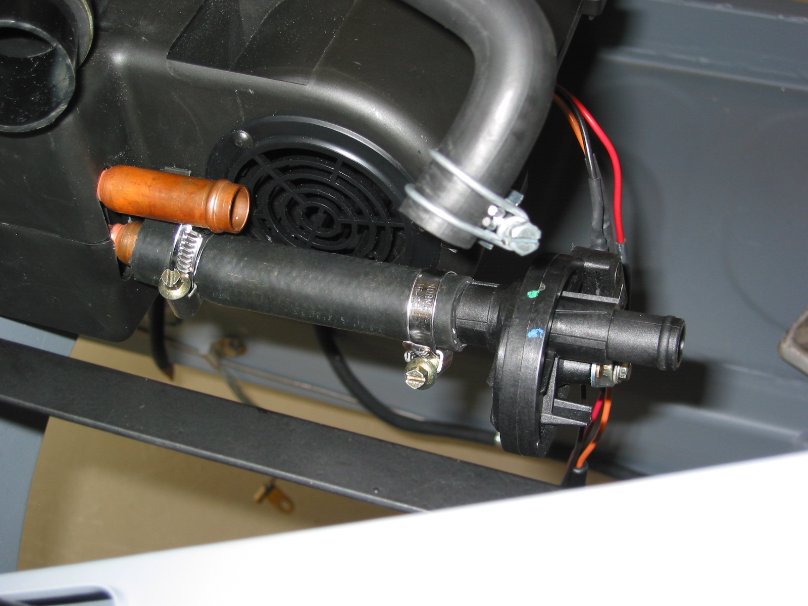
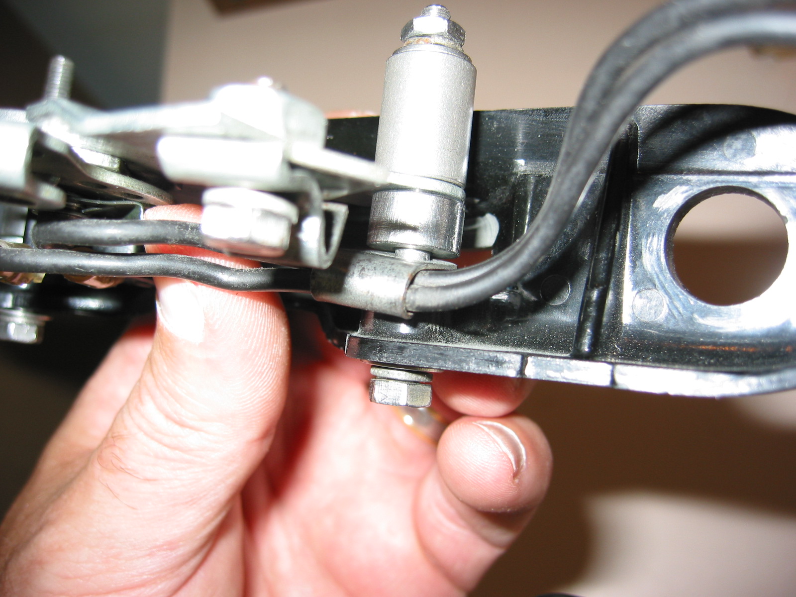
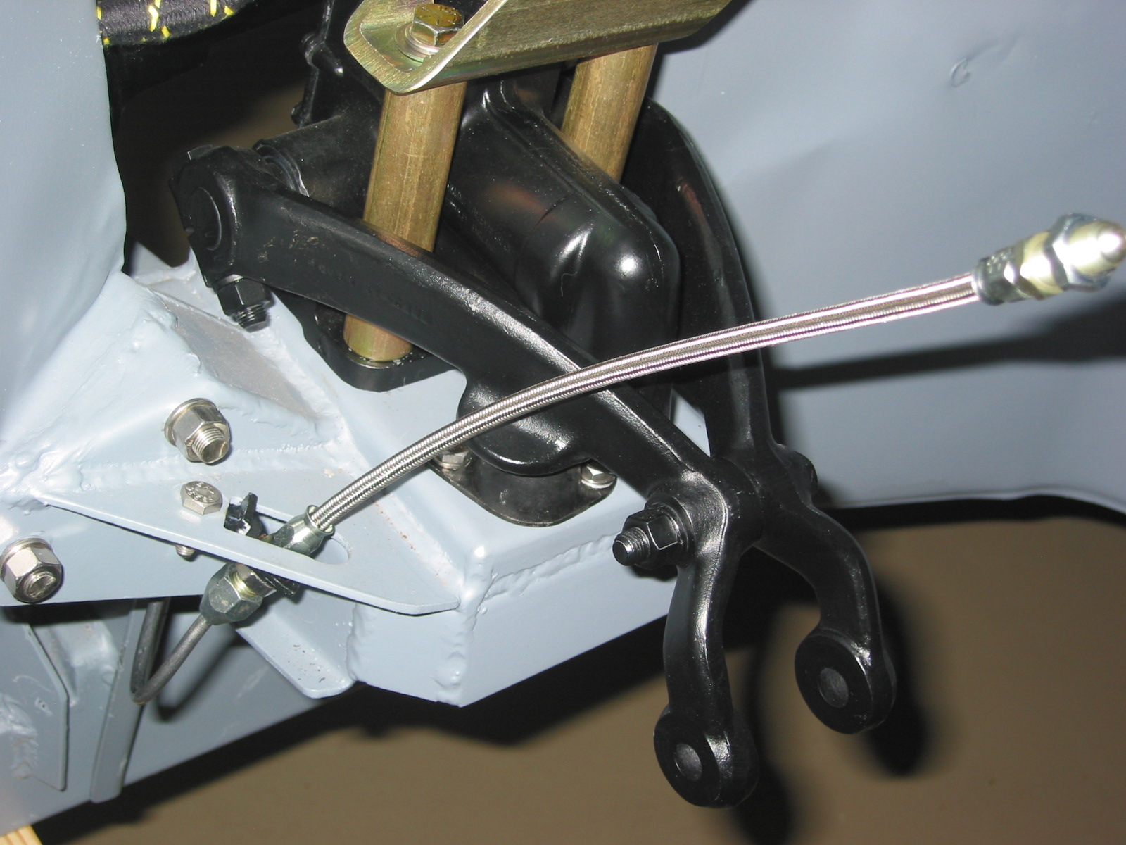
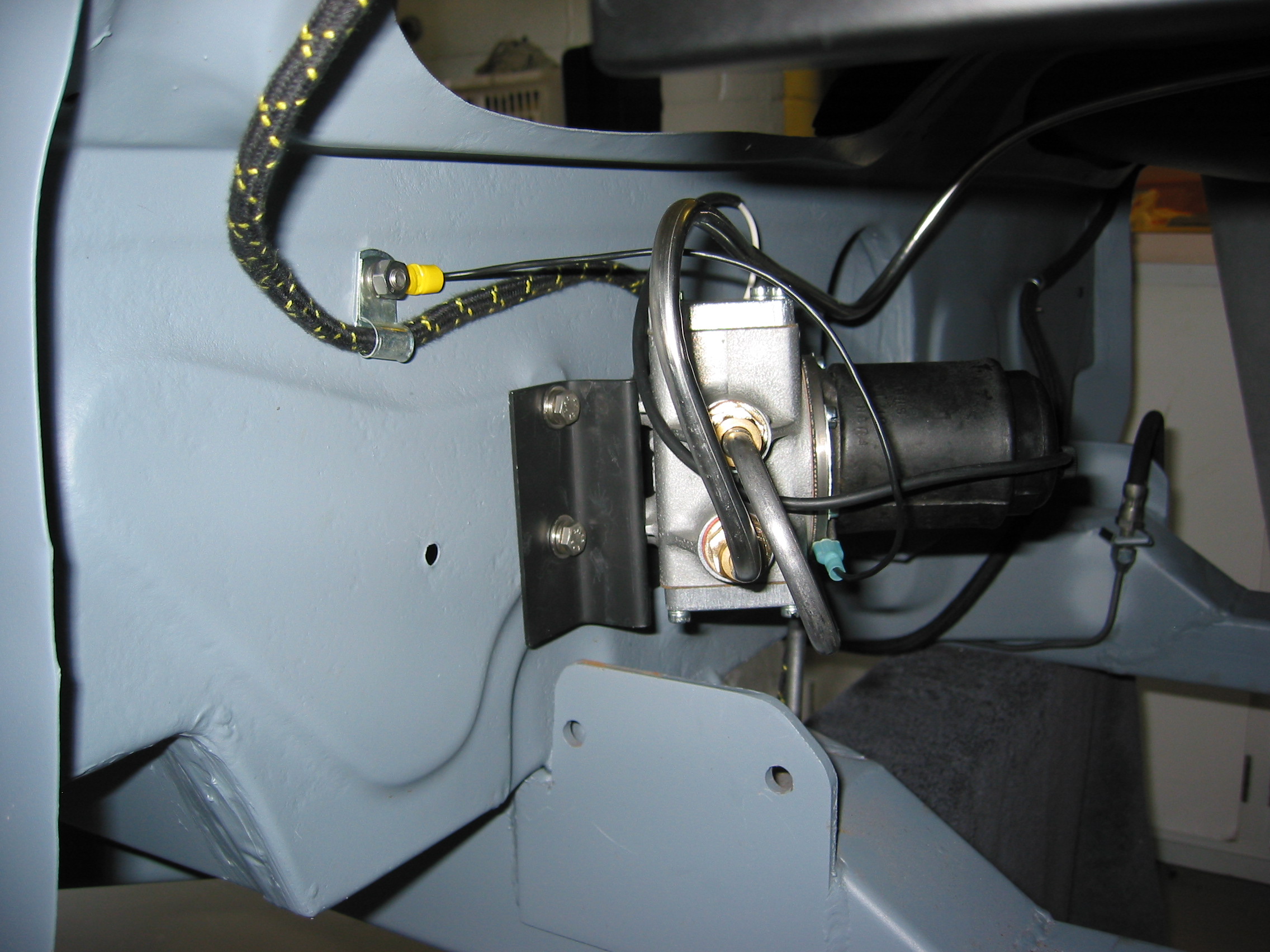
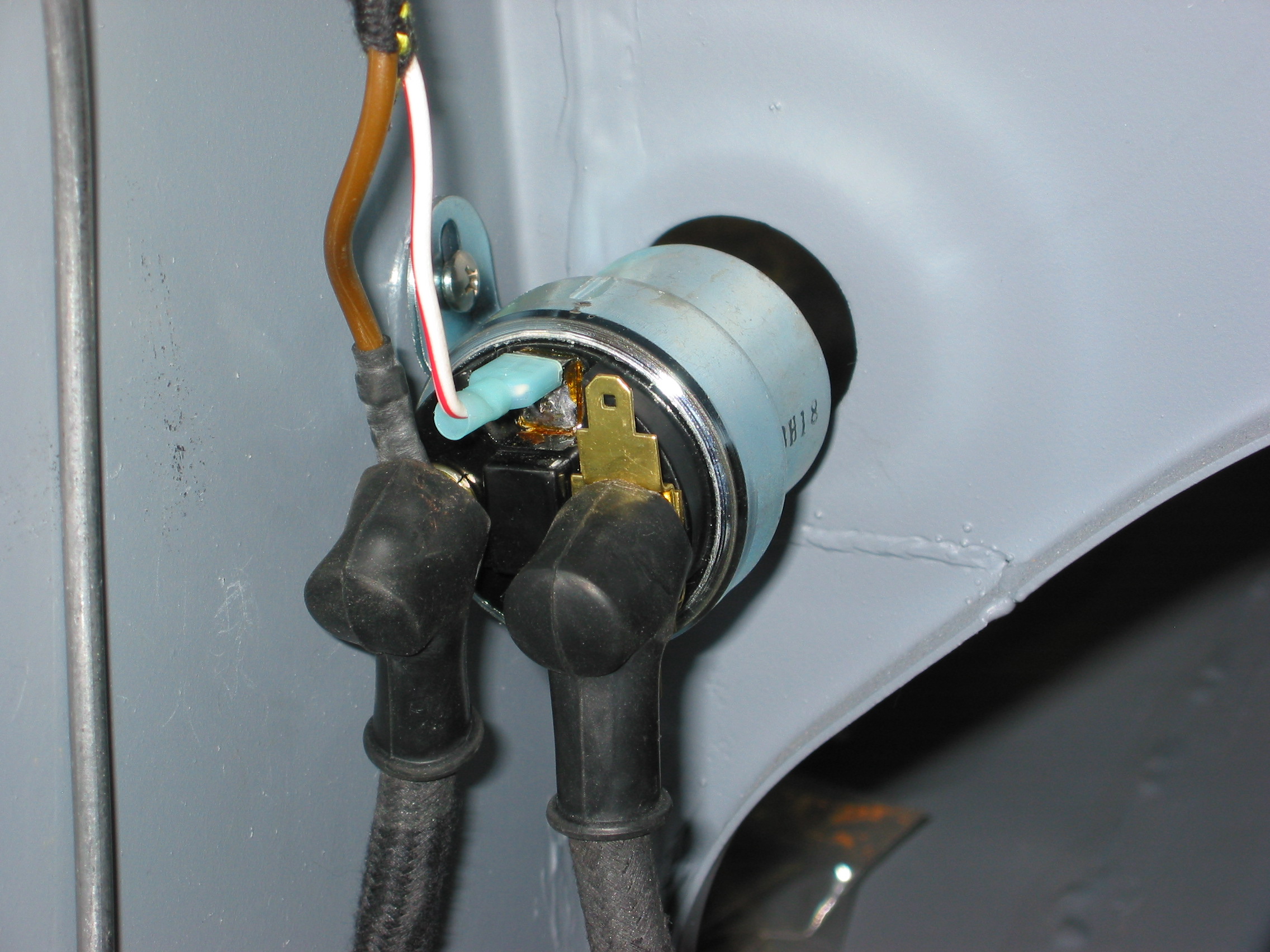
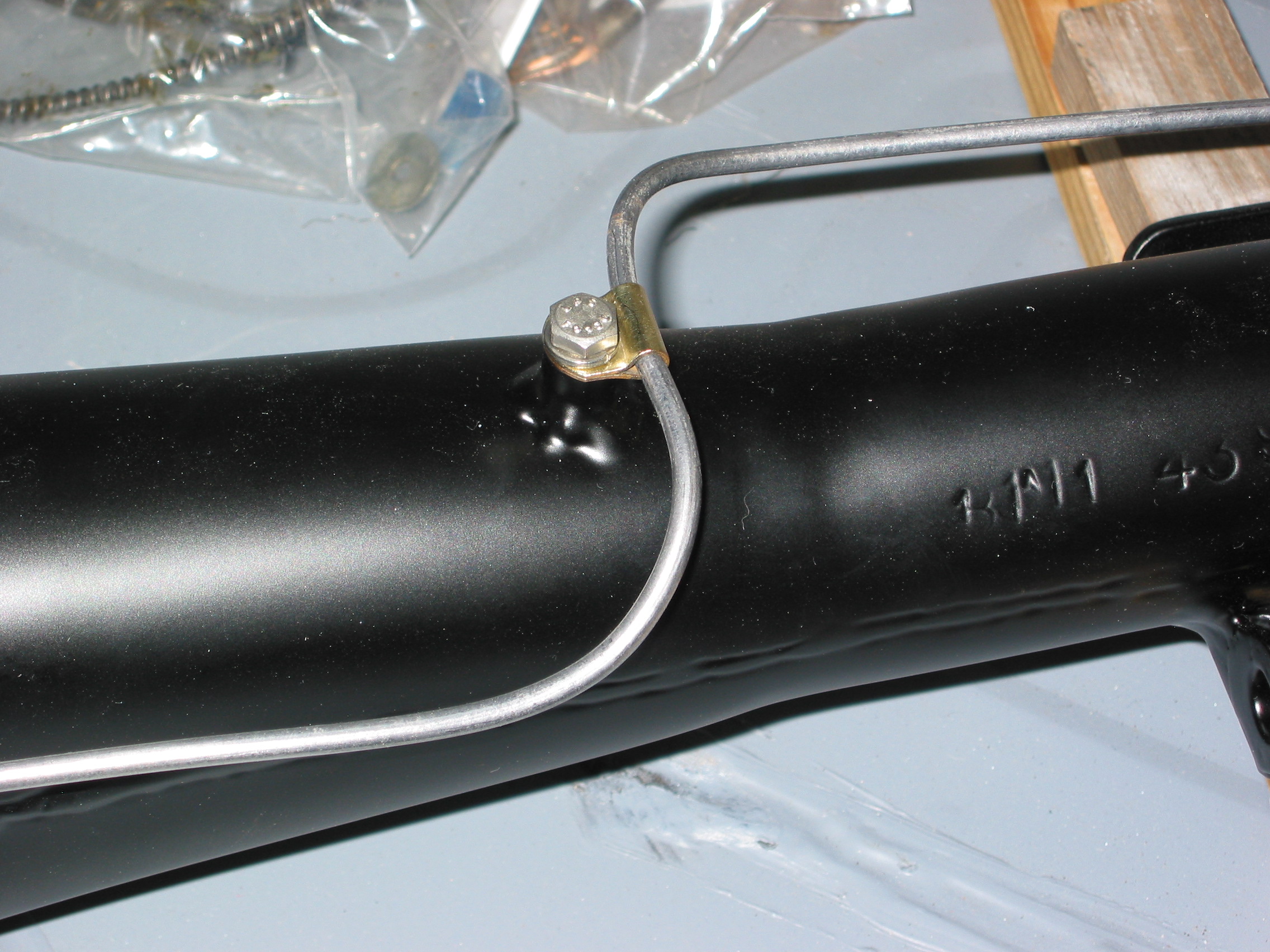
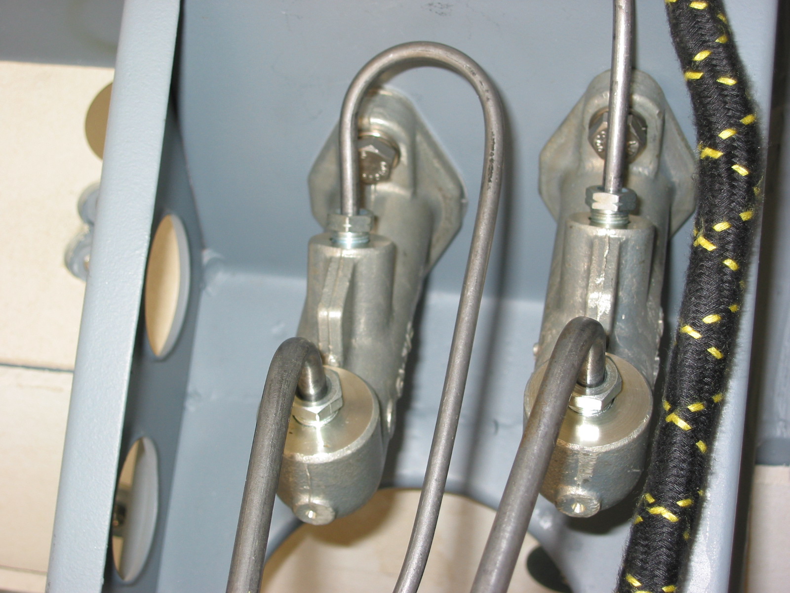
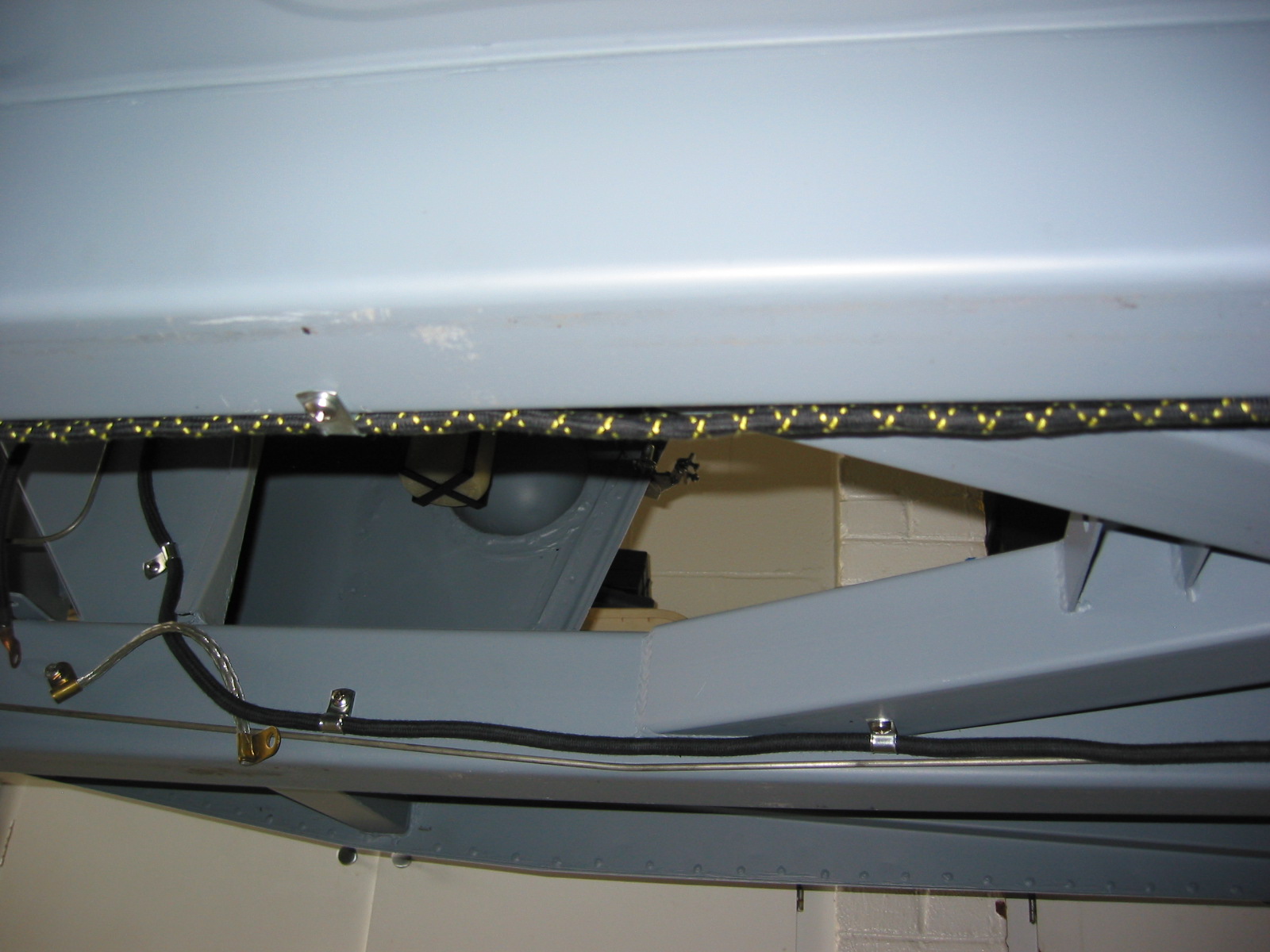
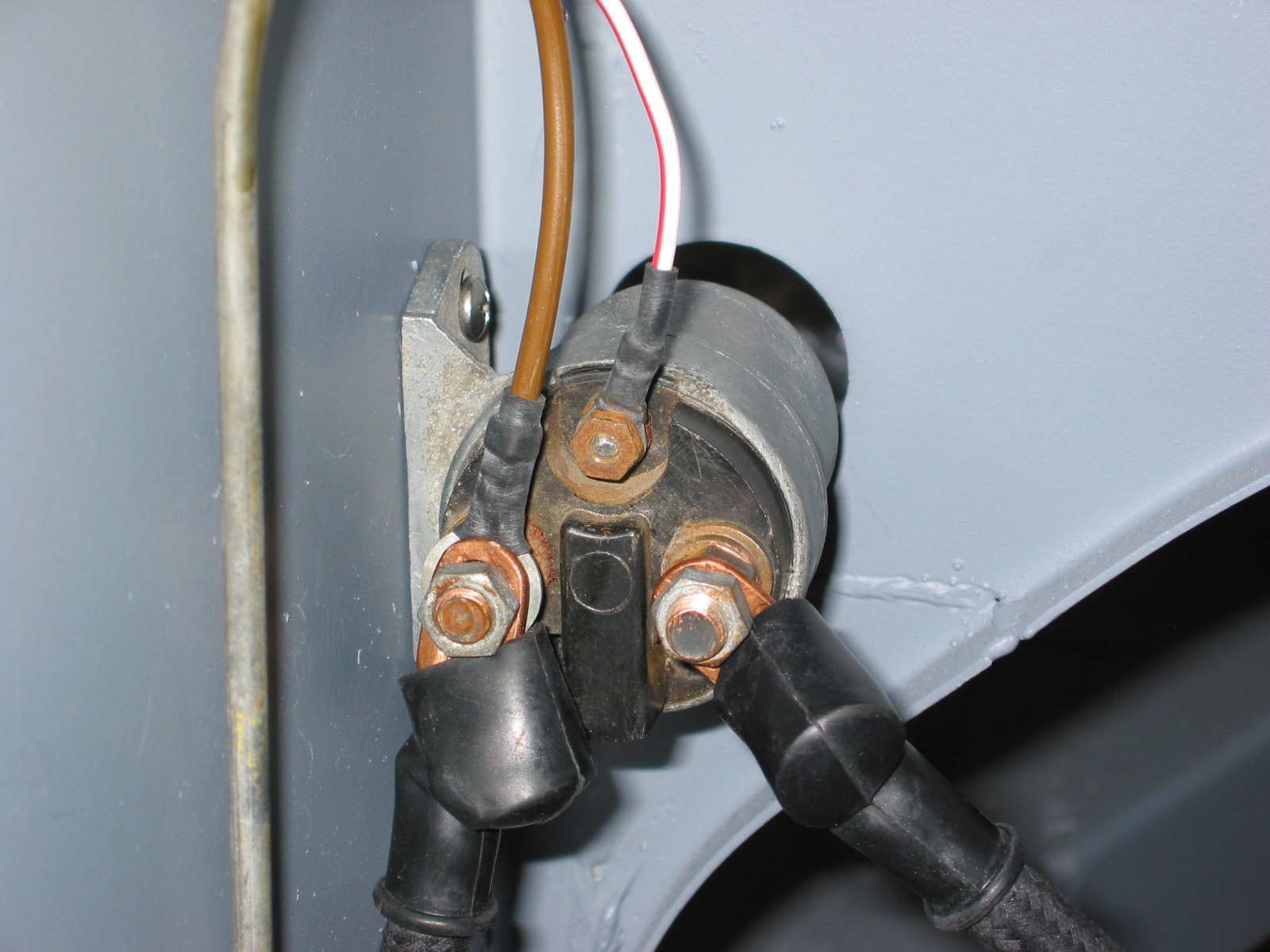
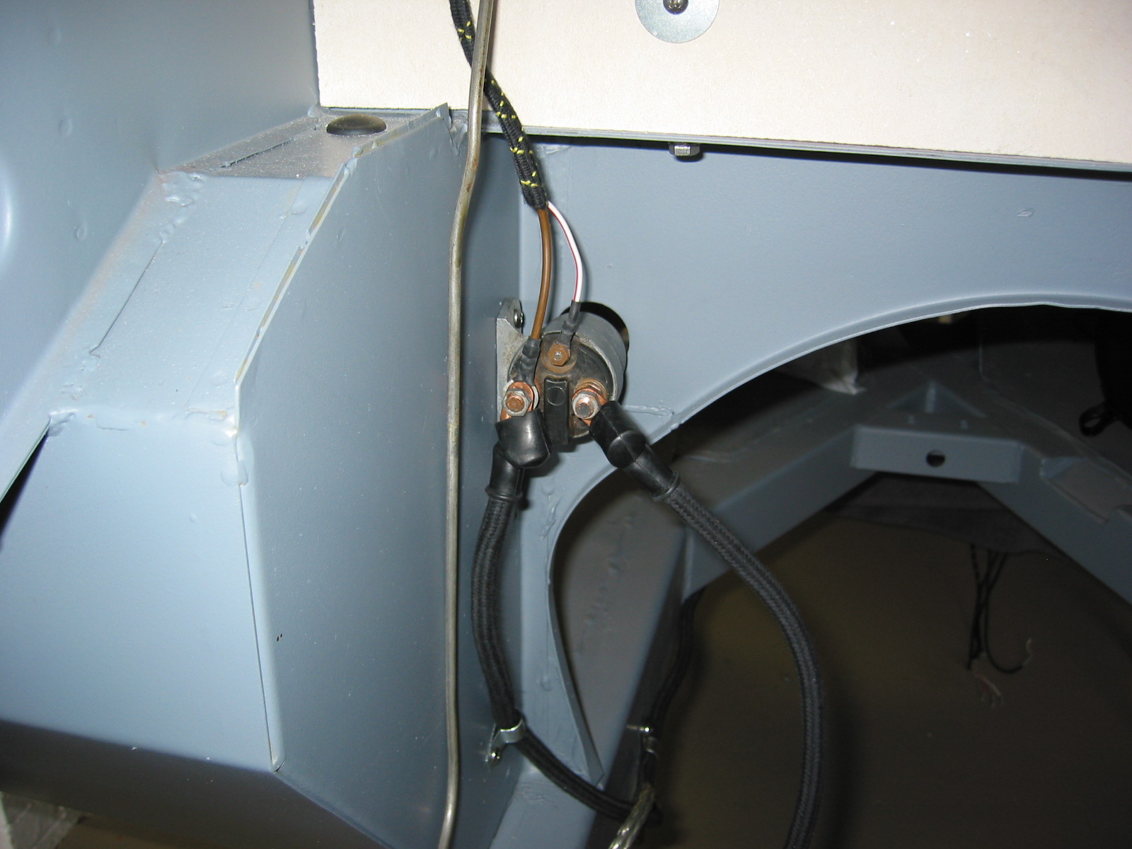
Power comes from a switched terminal on the ignition switch, and is connected to the new red wiring through an in-line fuse holder. From the other side of the switch, a new red wire carries power to the white wire on the pump. The “negative“ side – black wire – of the pump is grounded at the mounting bracket.
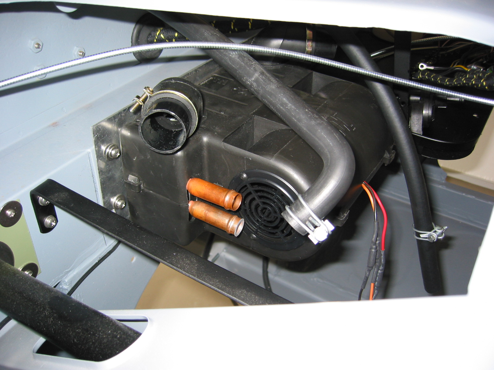
The connectors for the water tubing on the pump are larger than that used on the shroud fittings and the tube from the reservoir. I purchased a plastic transition piece that fit the larger fitting on the pump and the smaller fittings elsewhere.
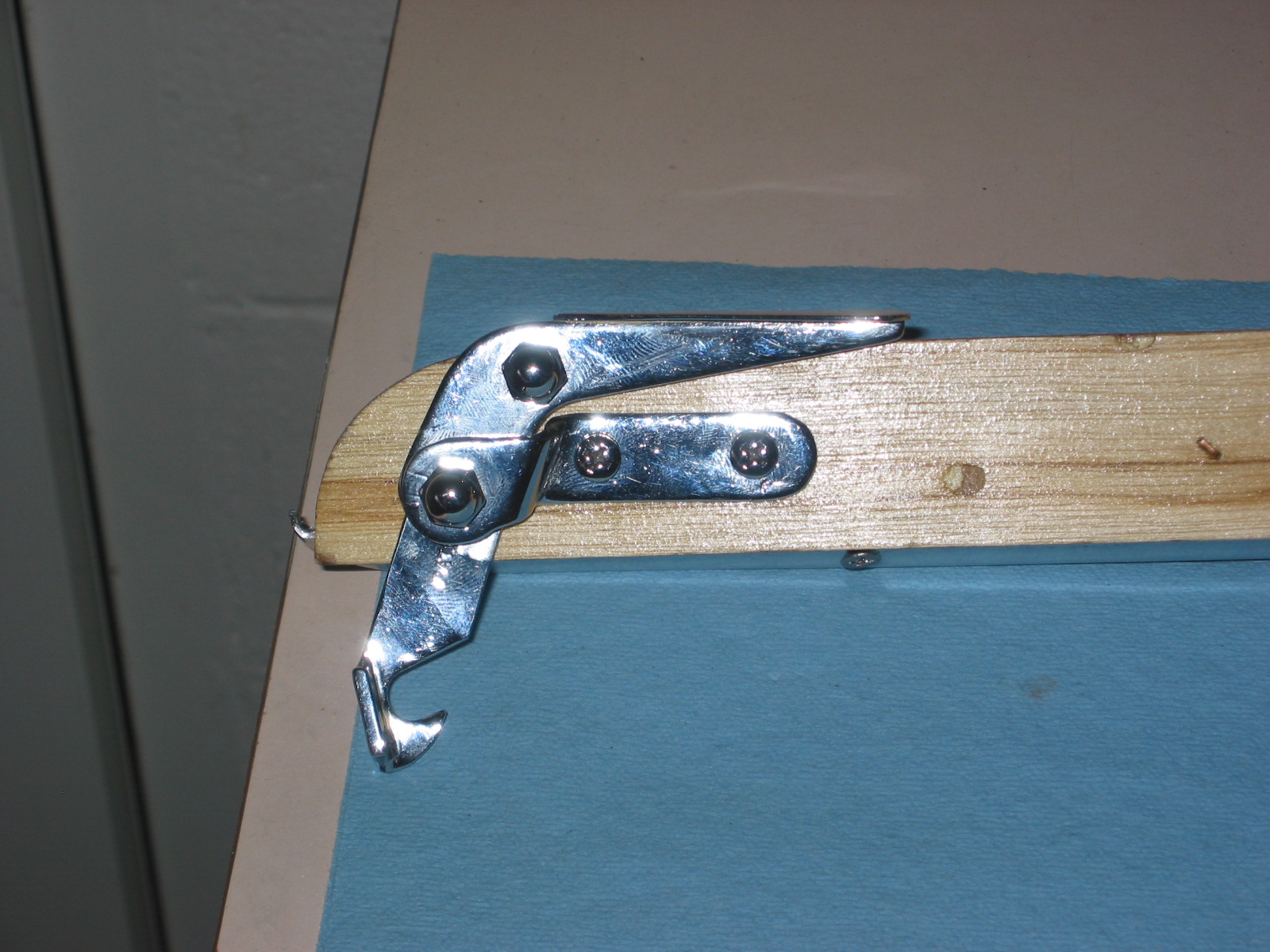
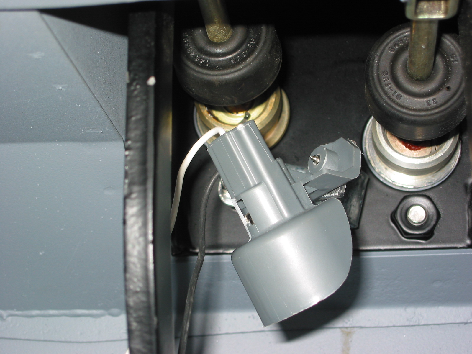
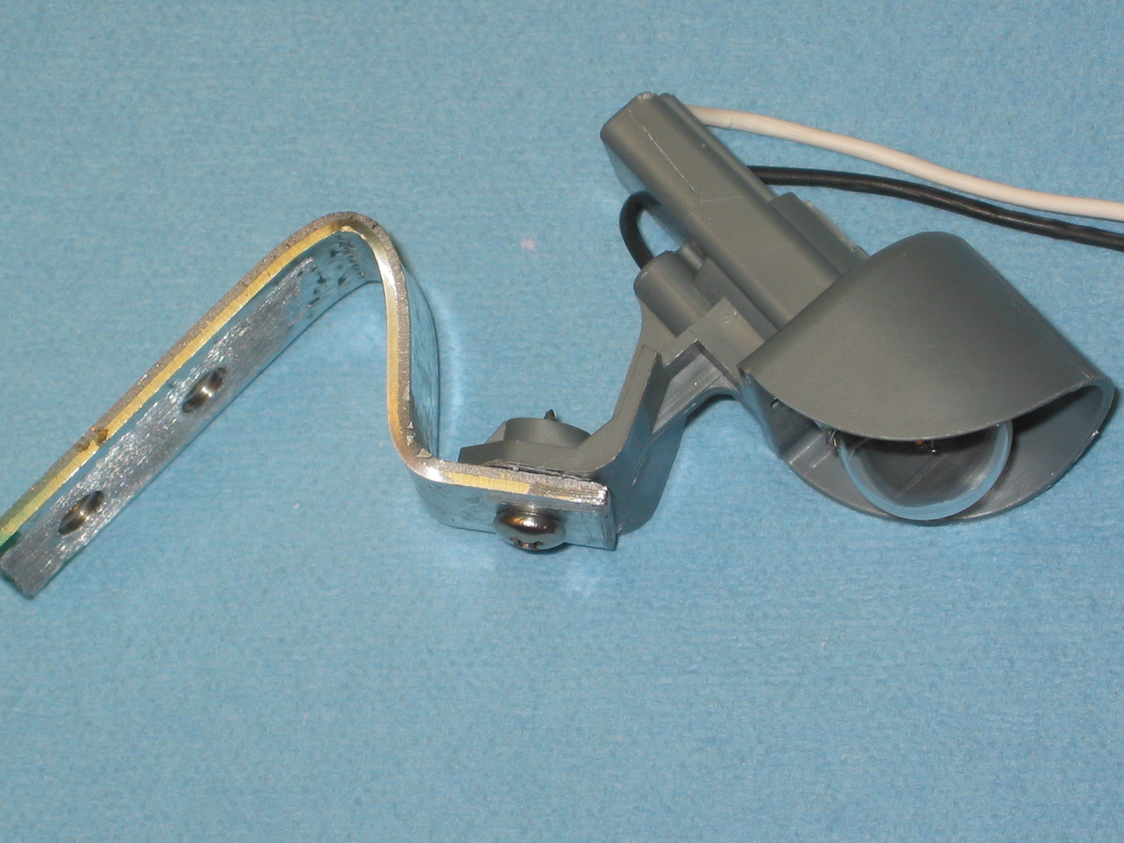
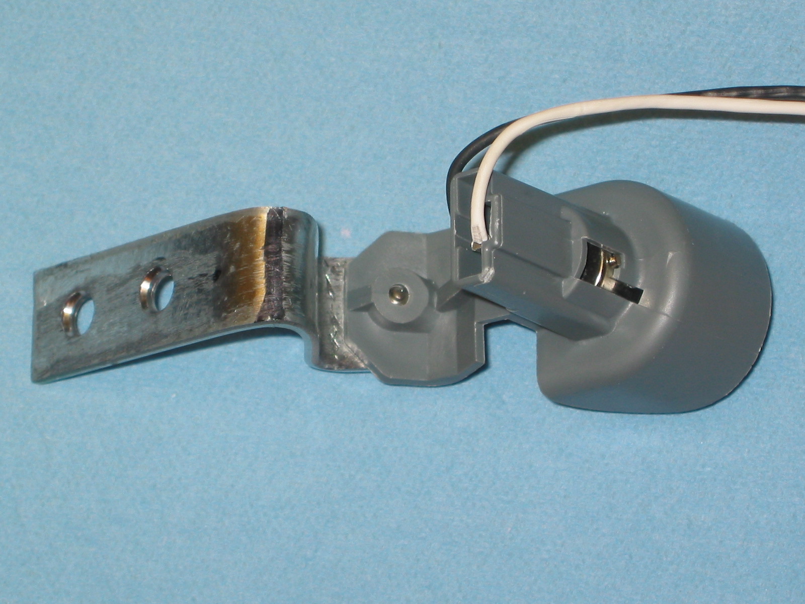
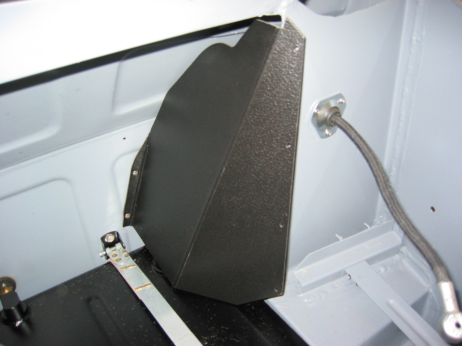
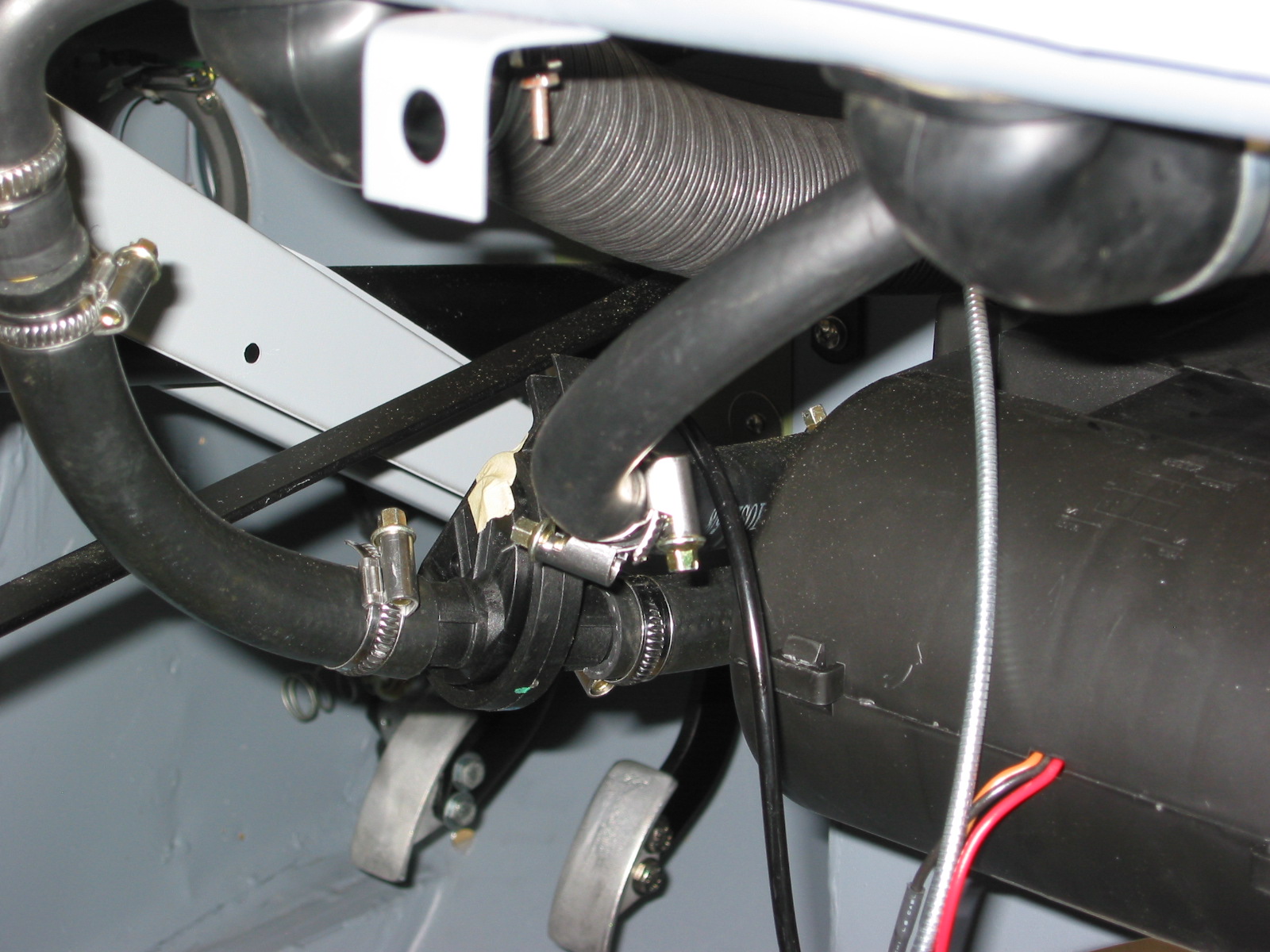
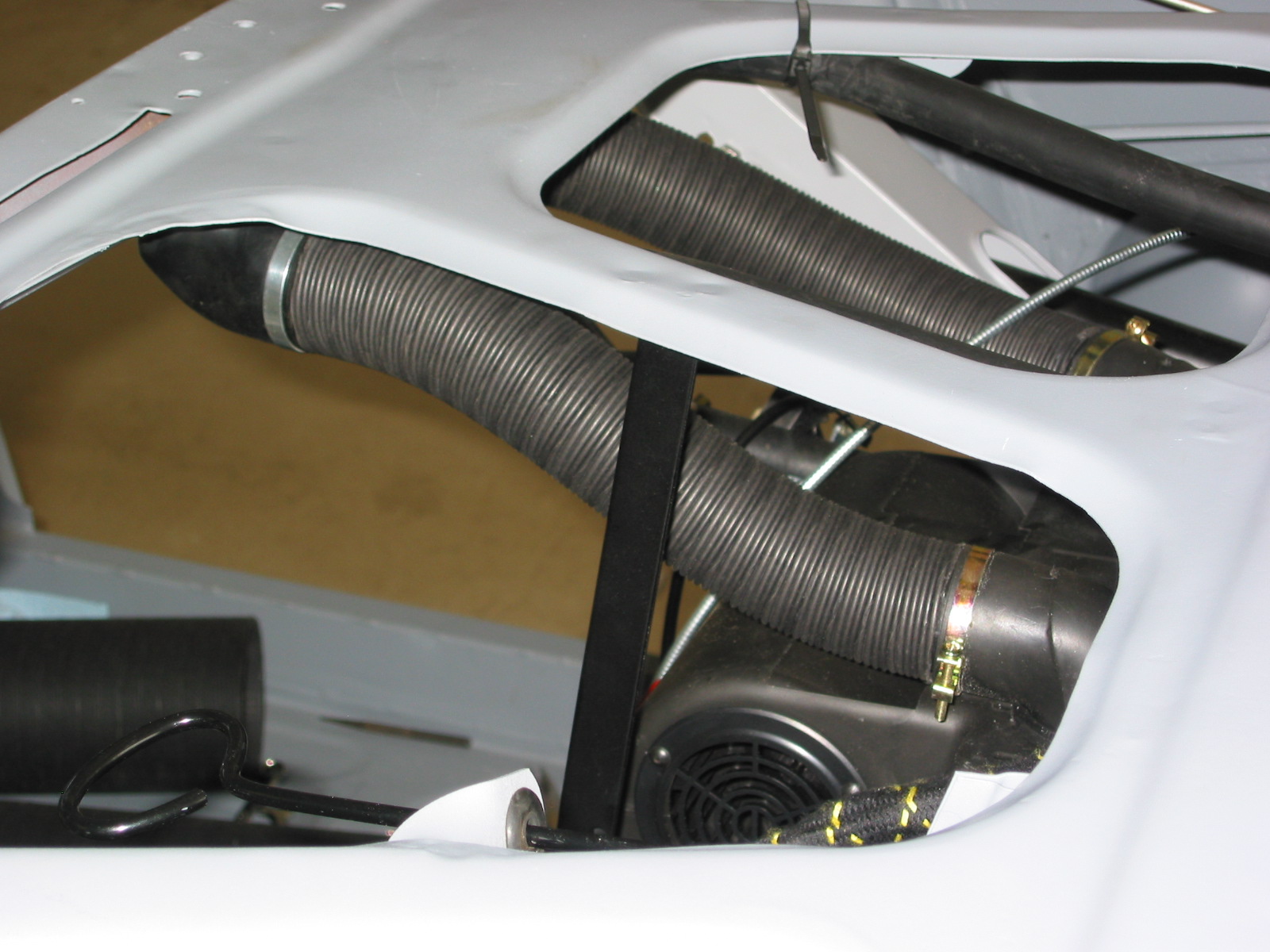
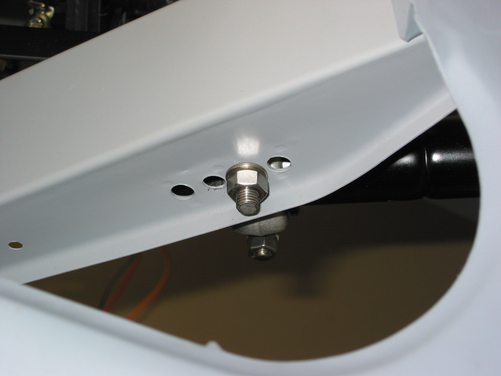
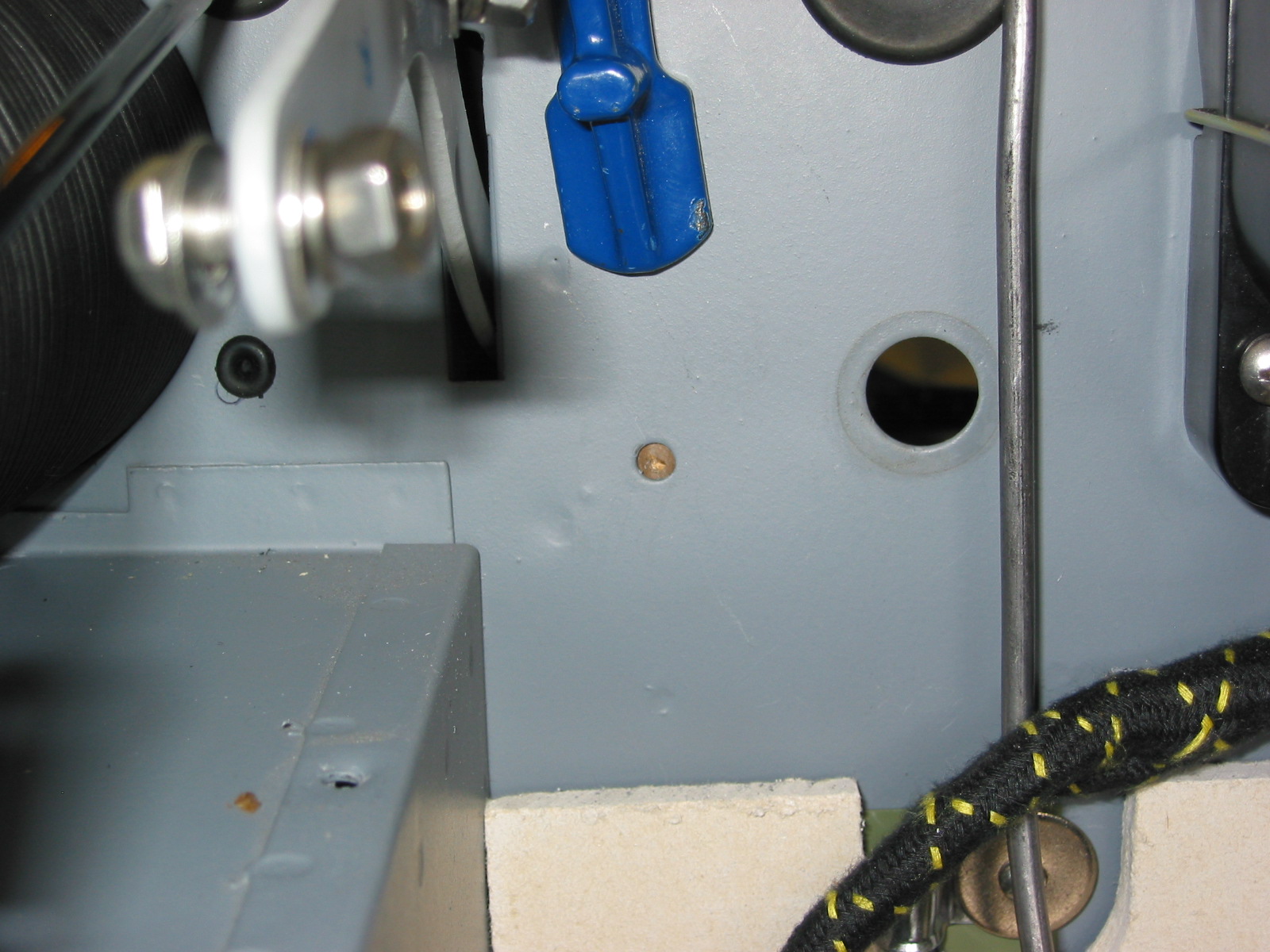
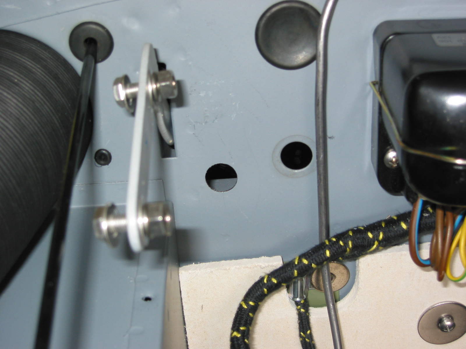
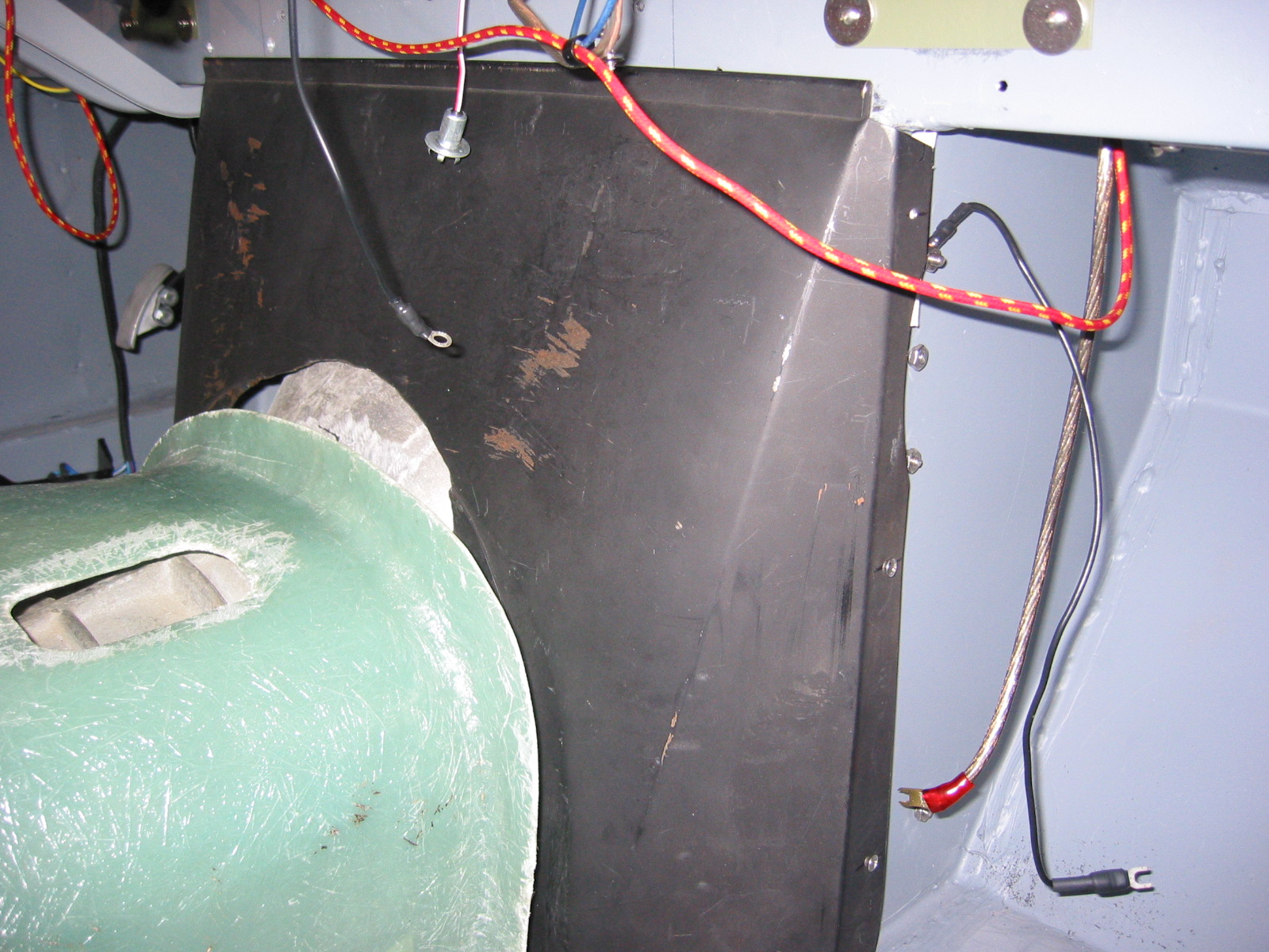
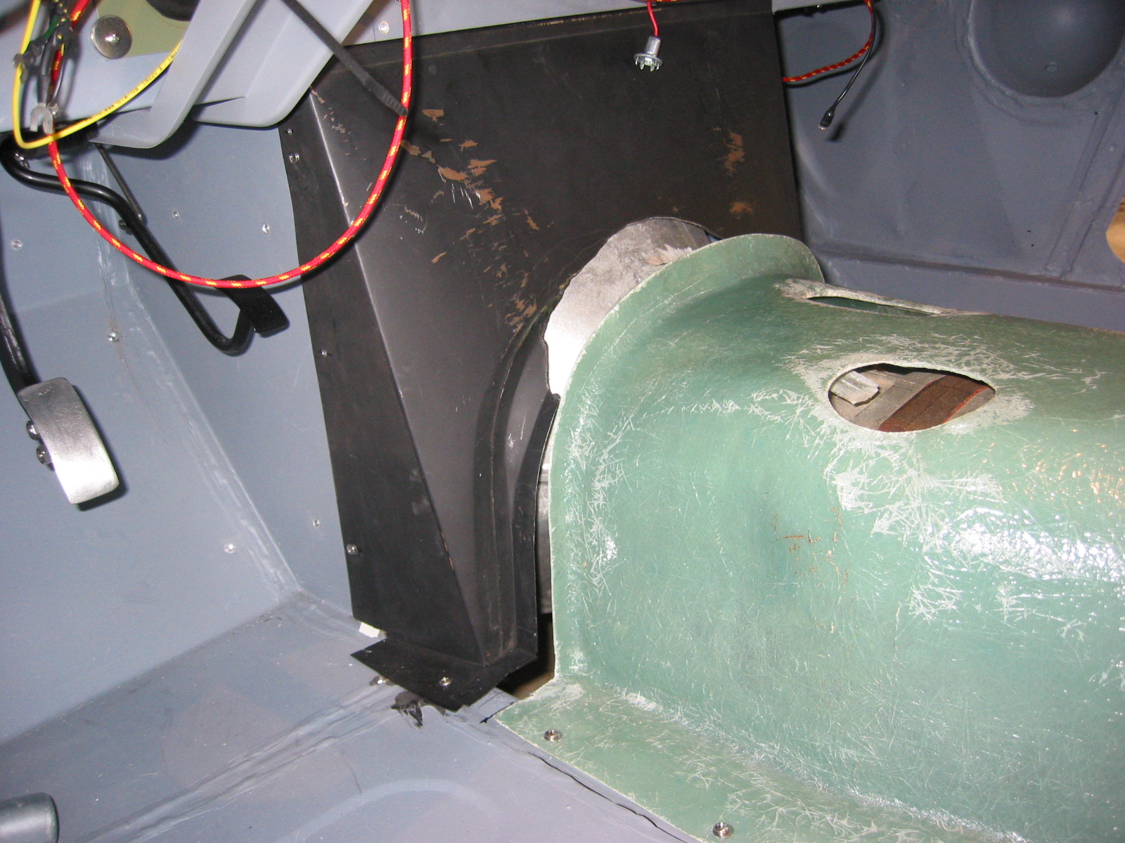
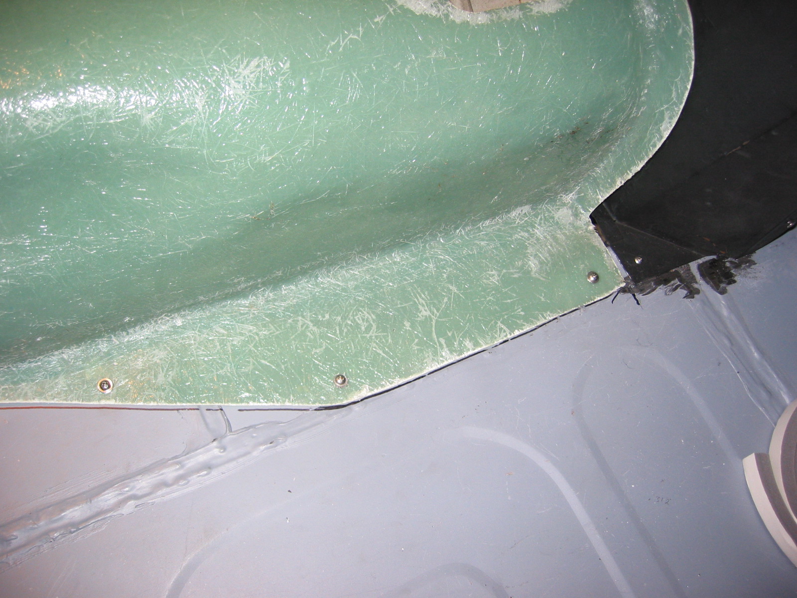
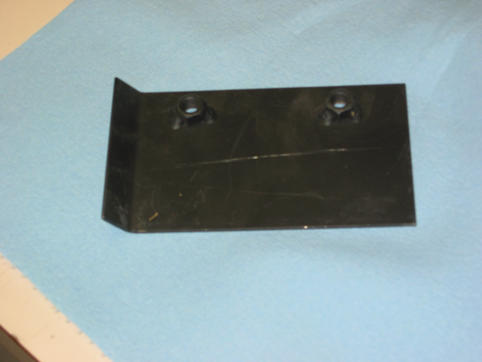
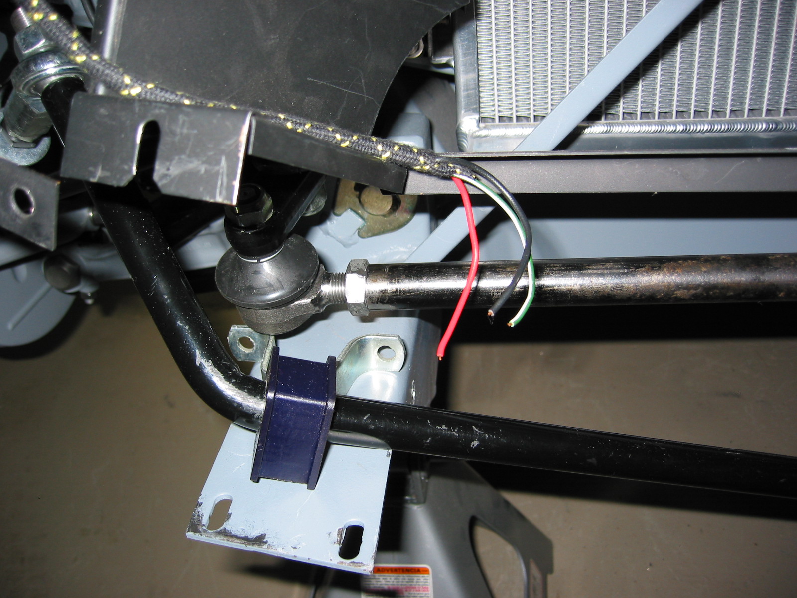
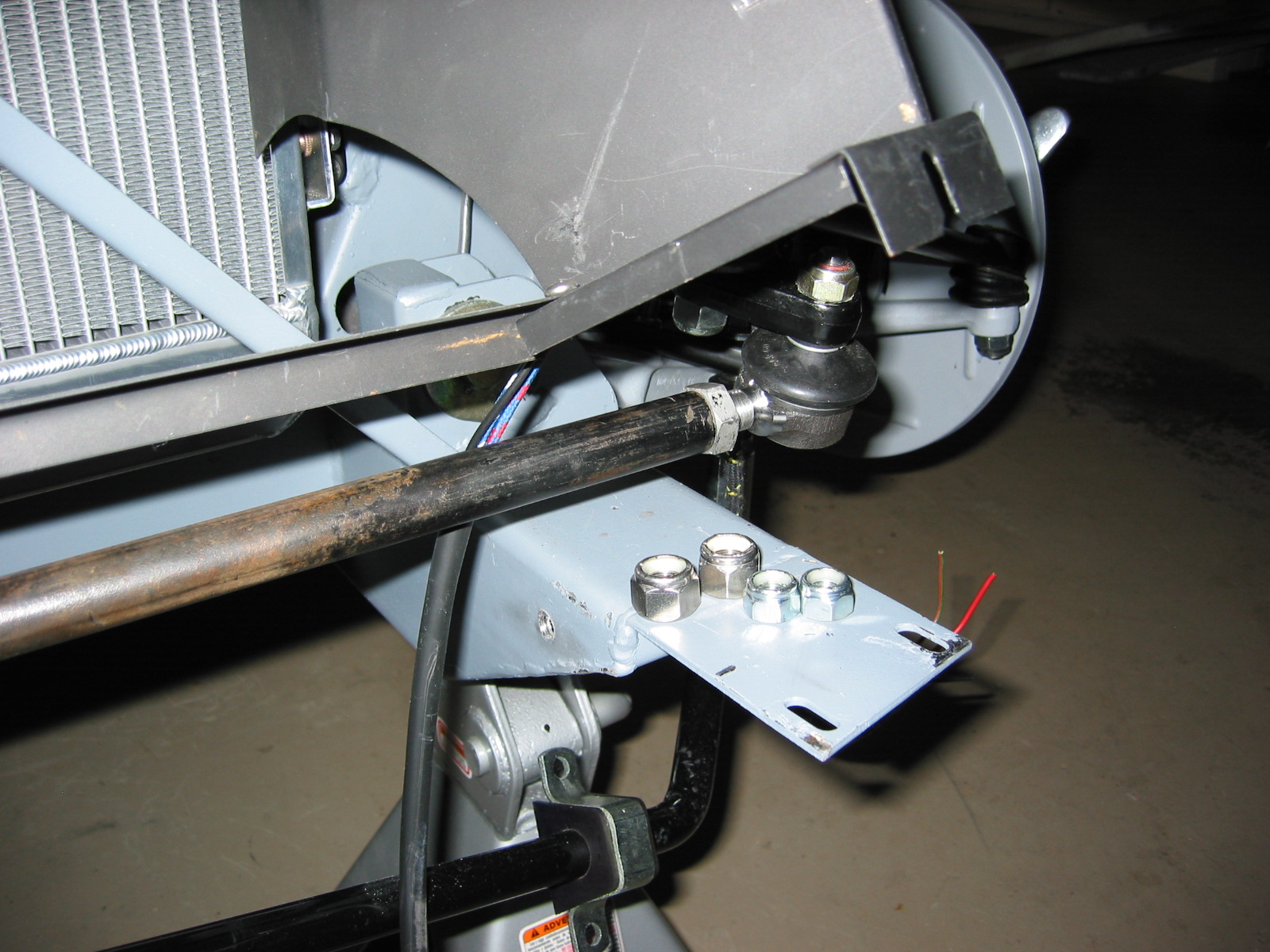
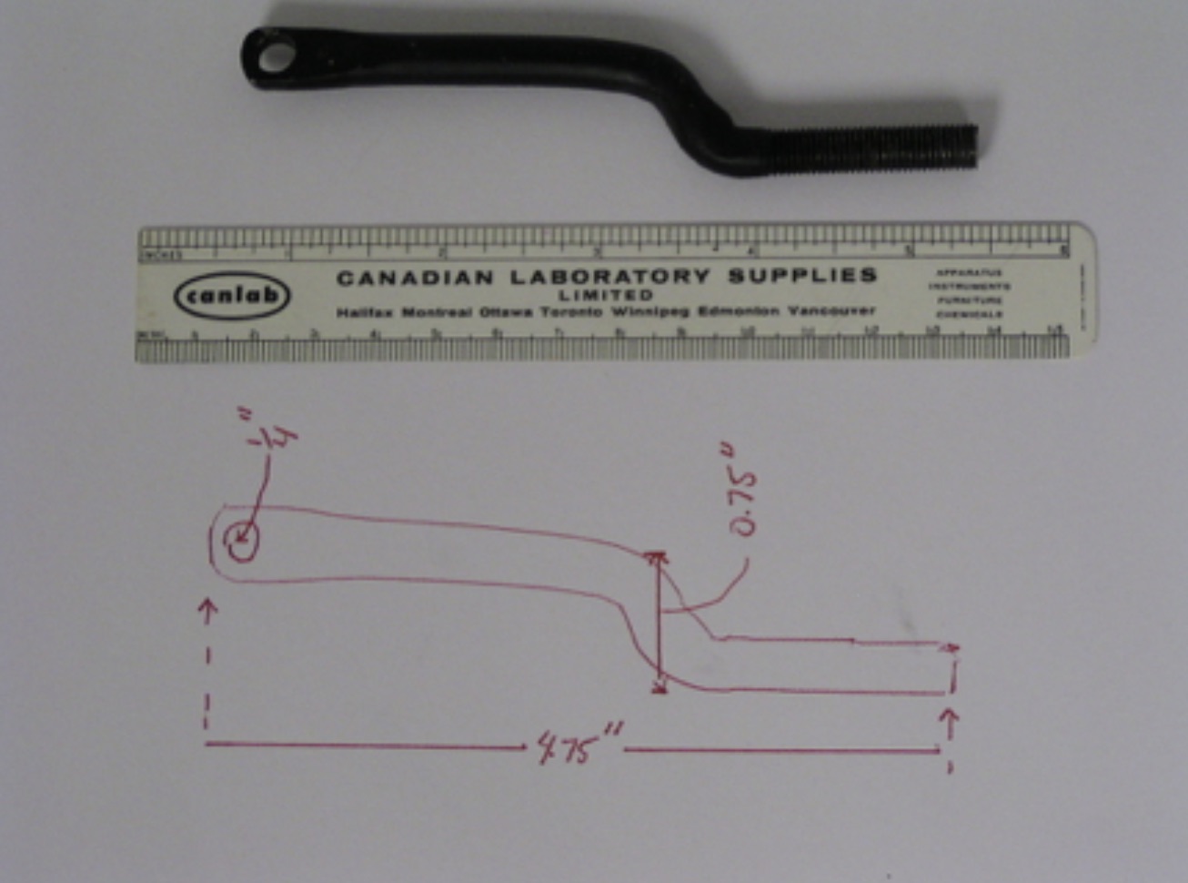
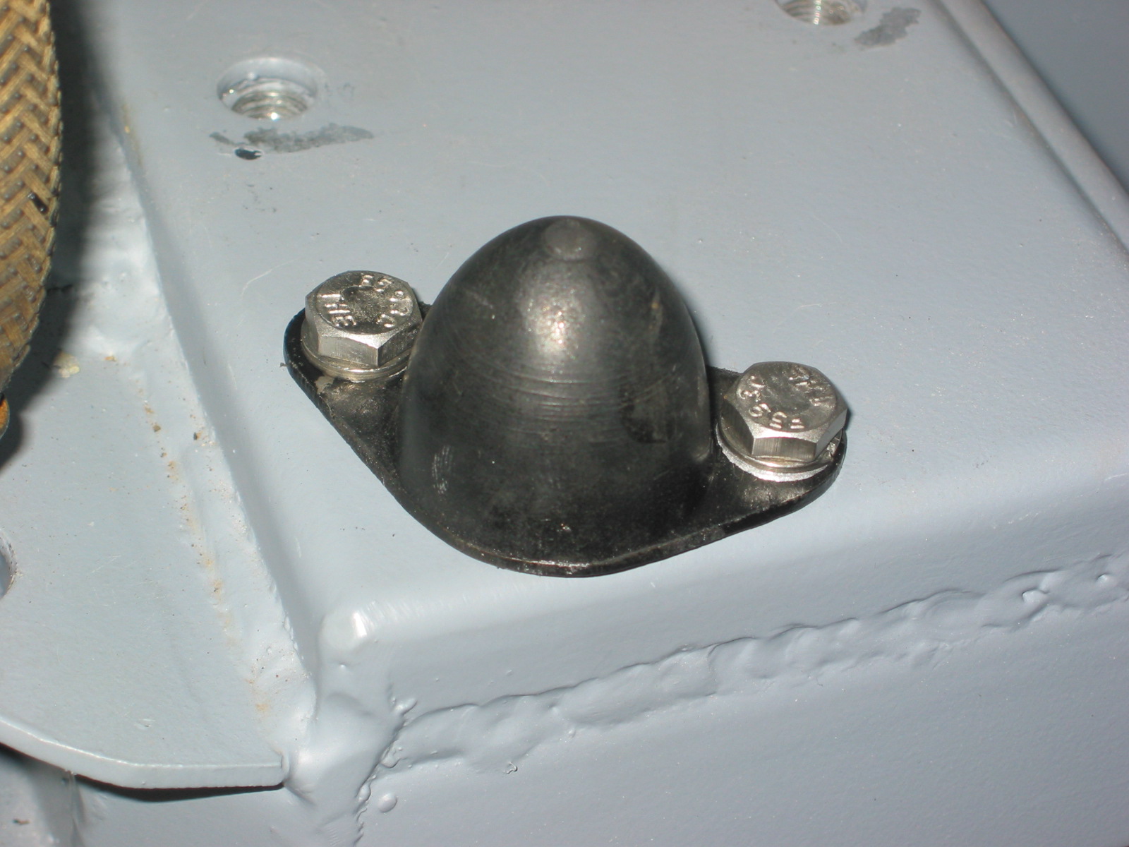
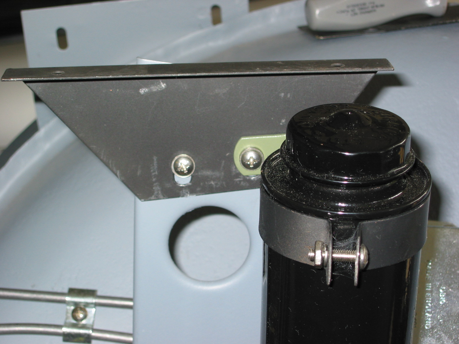
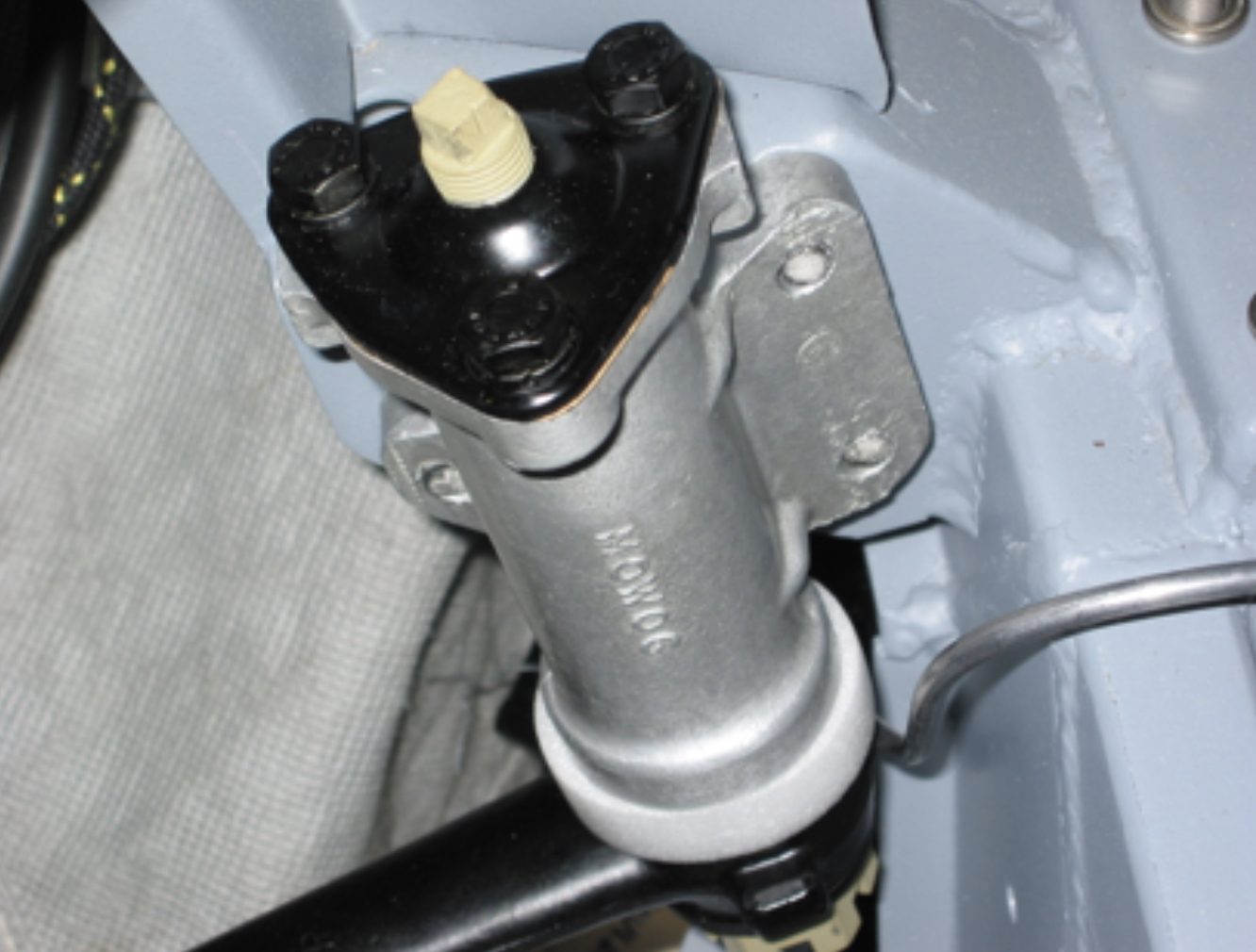
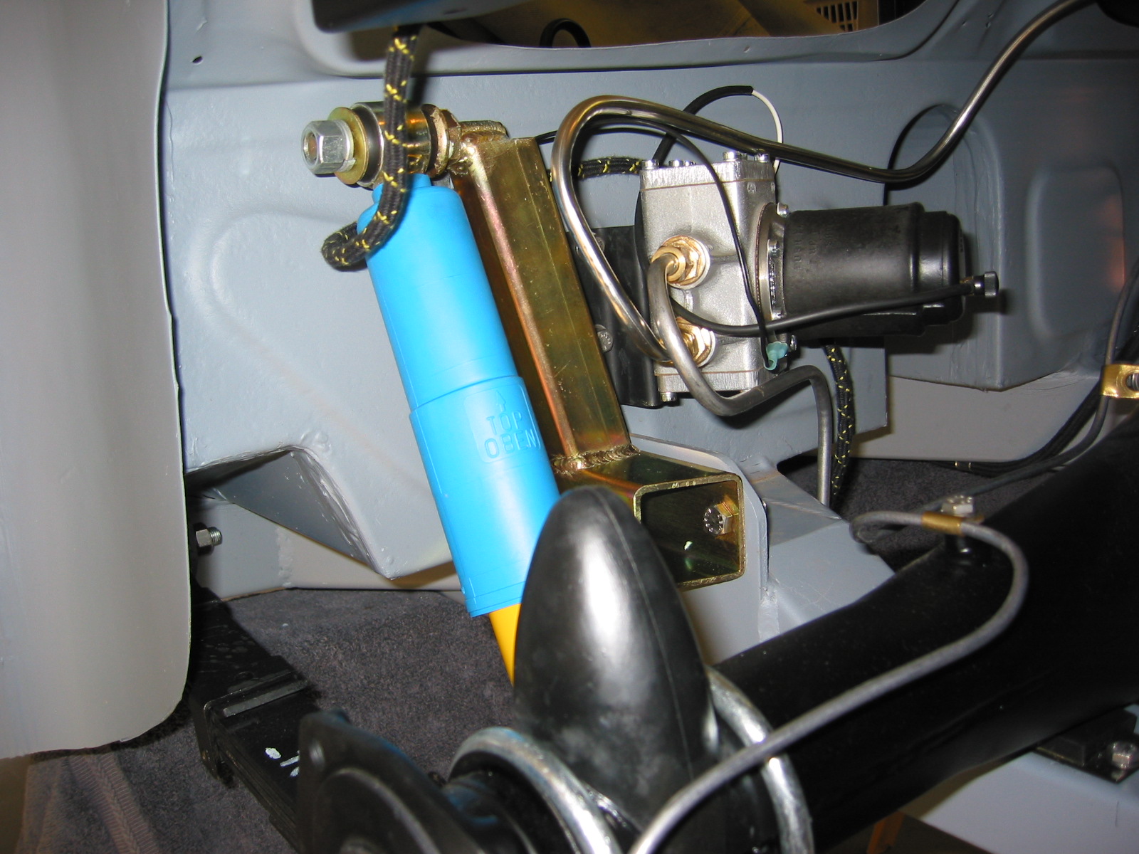
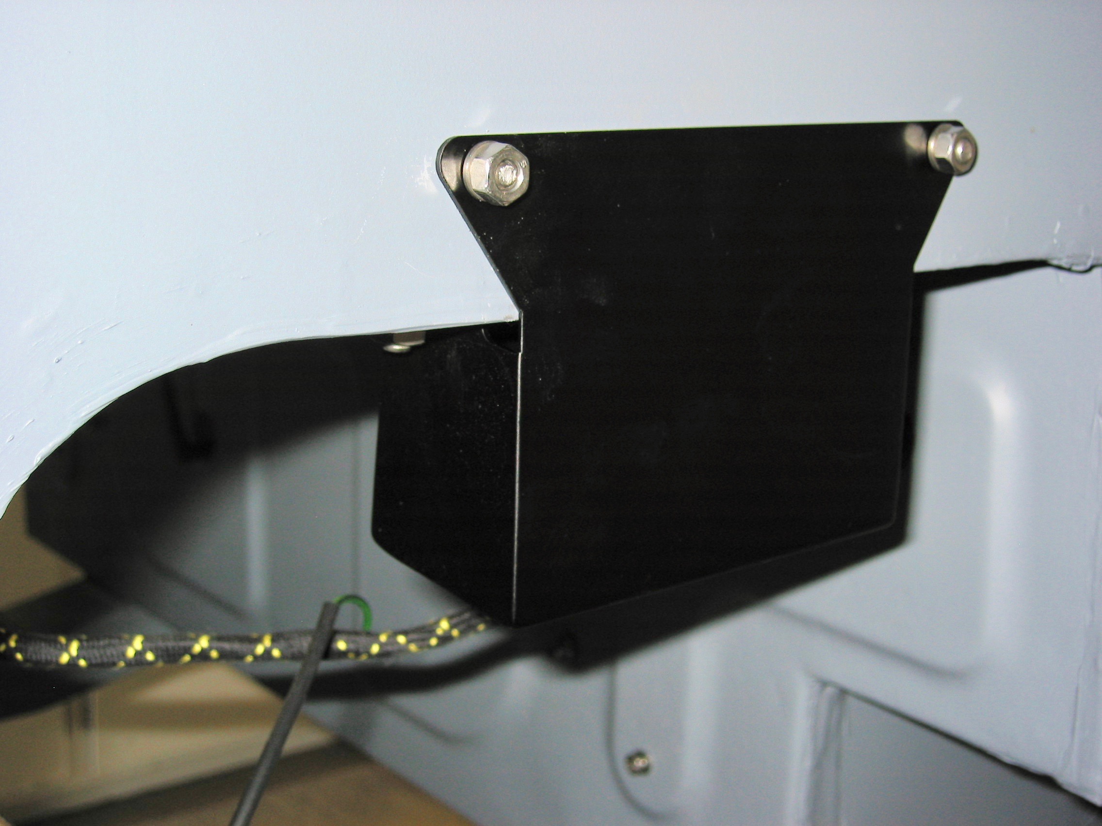
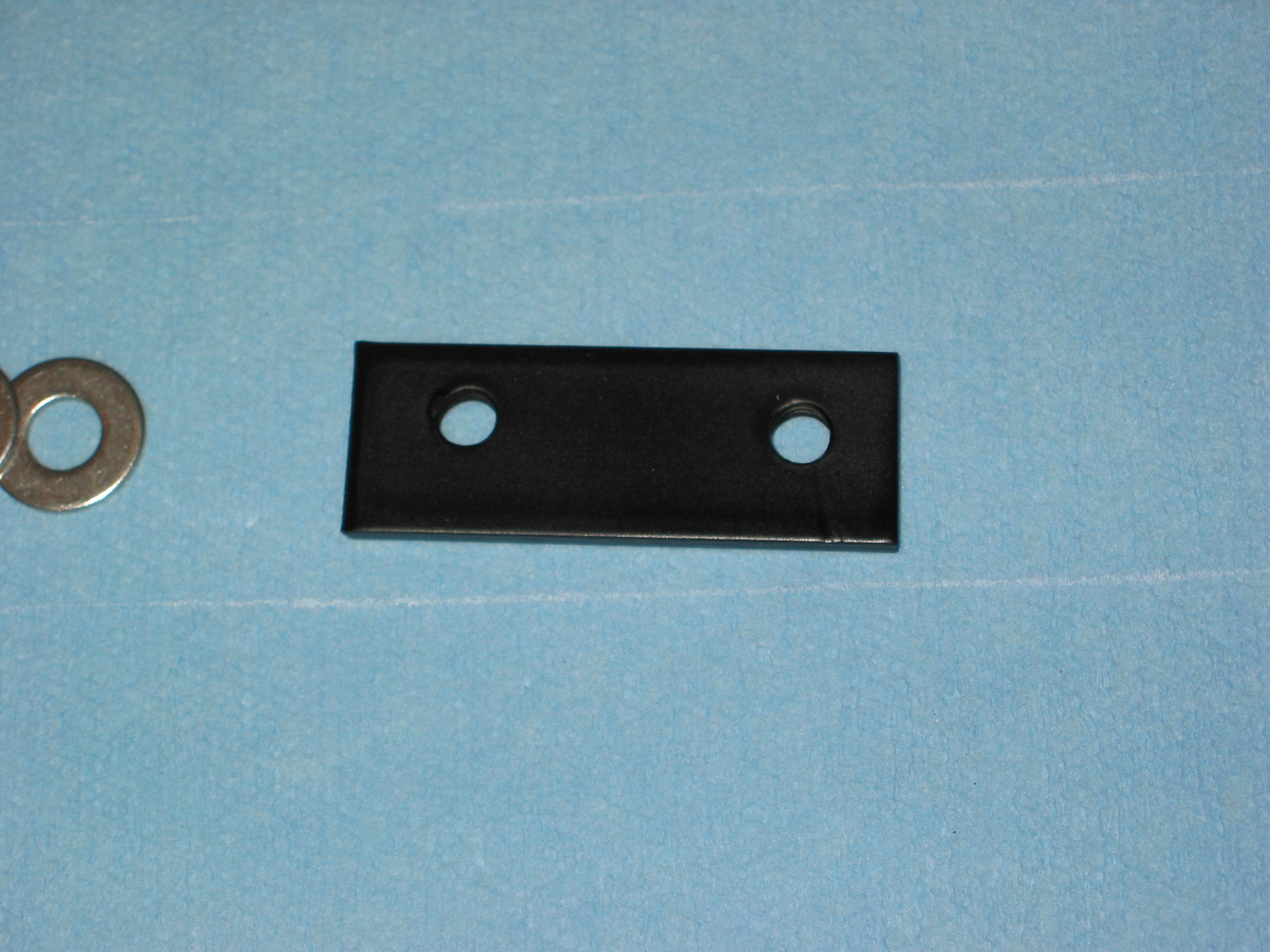
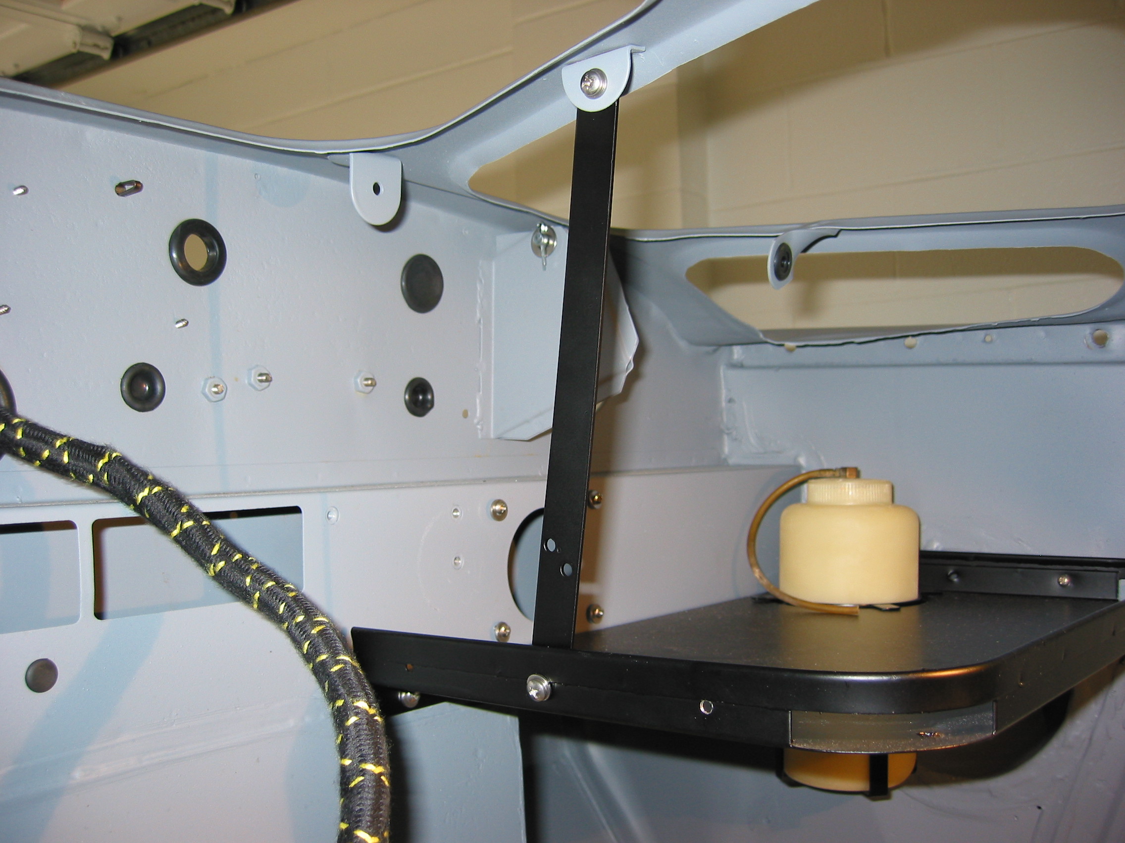
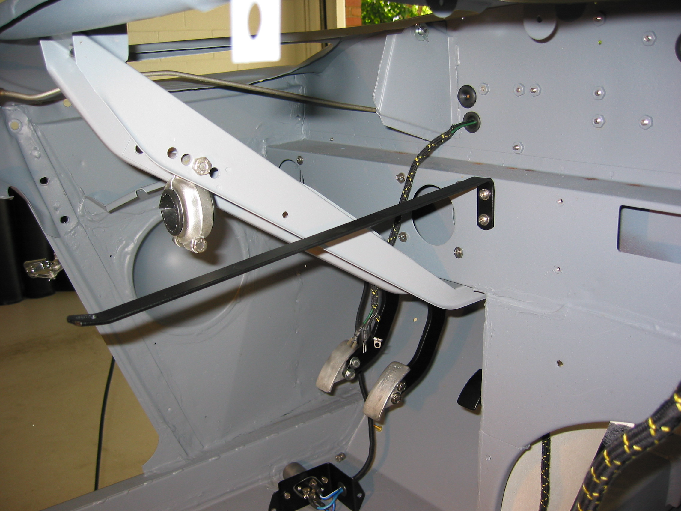
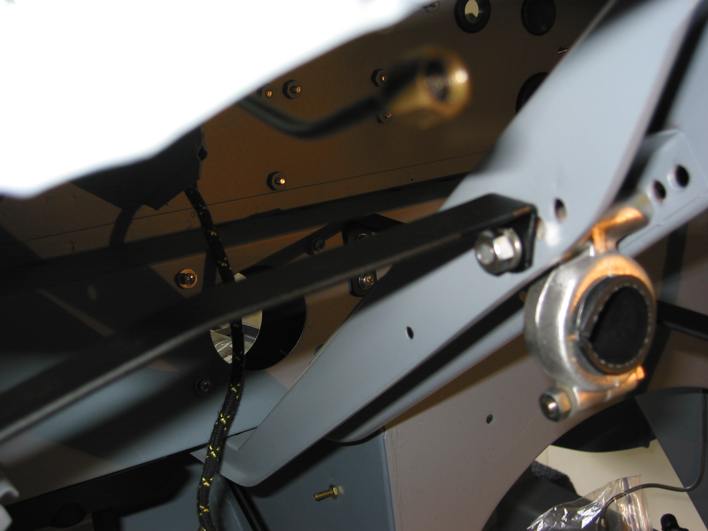
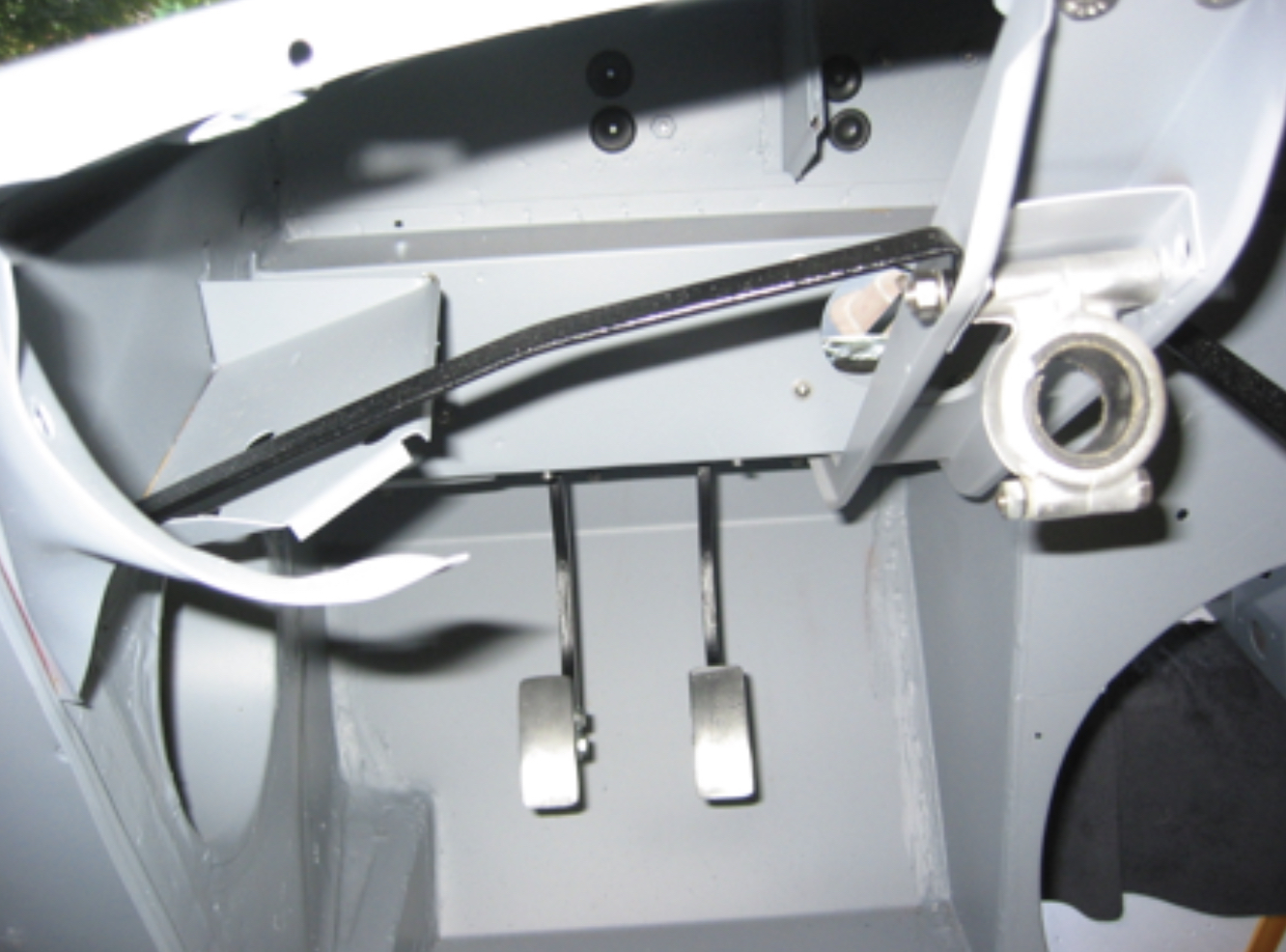
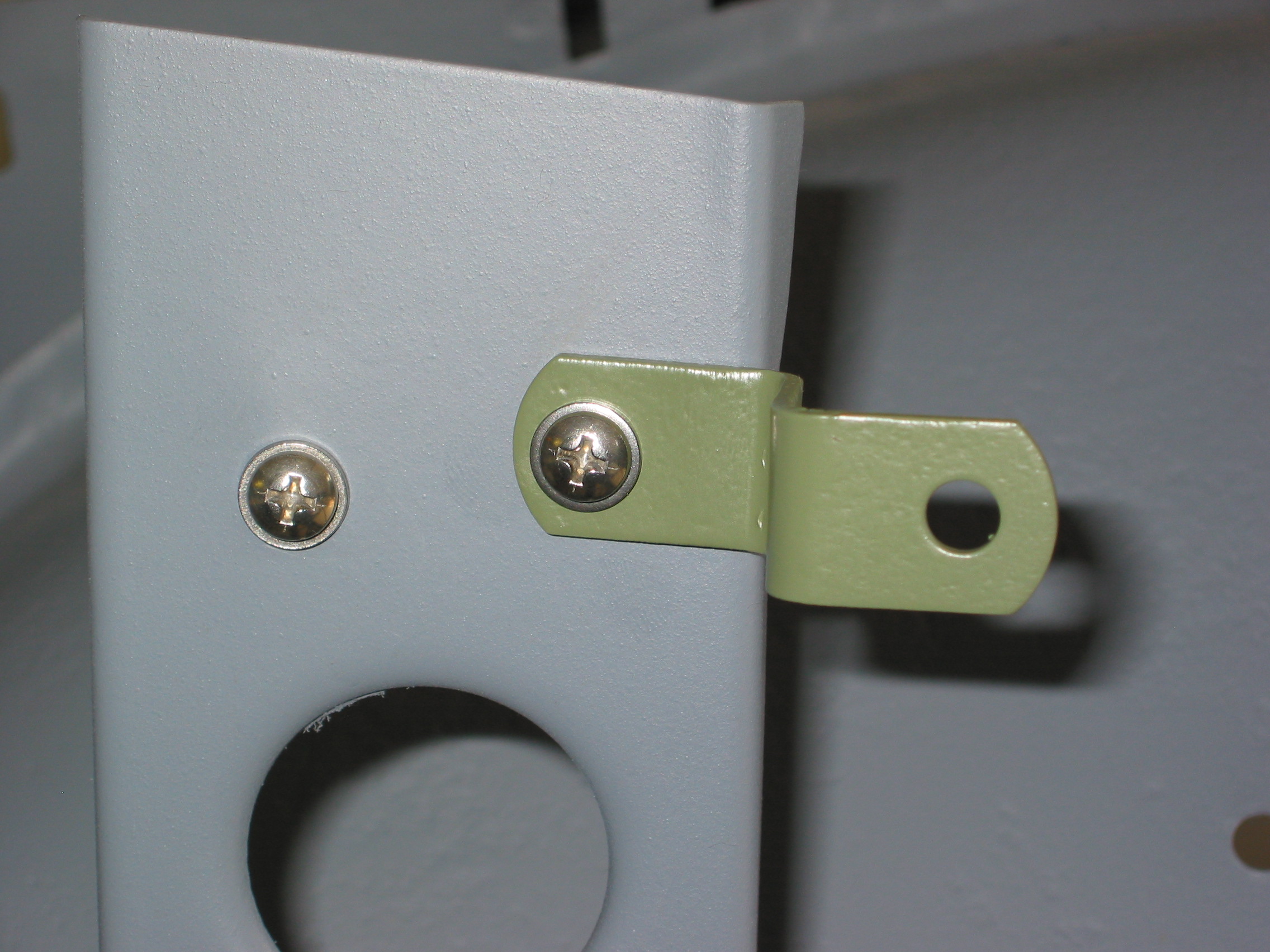
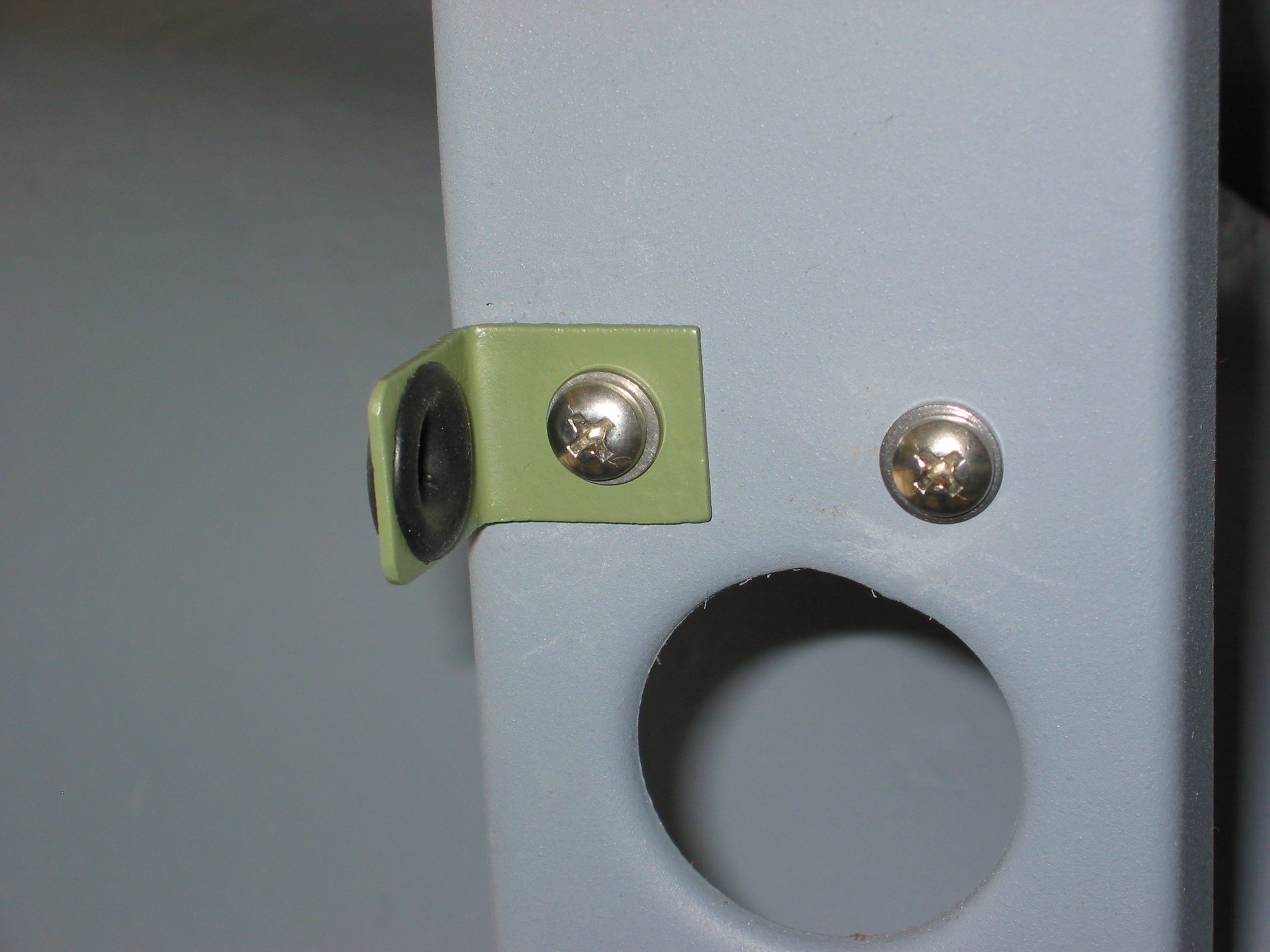
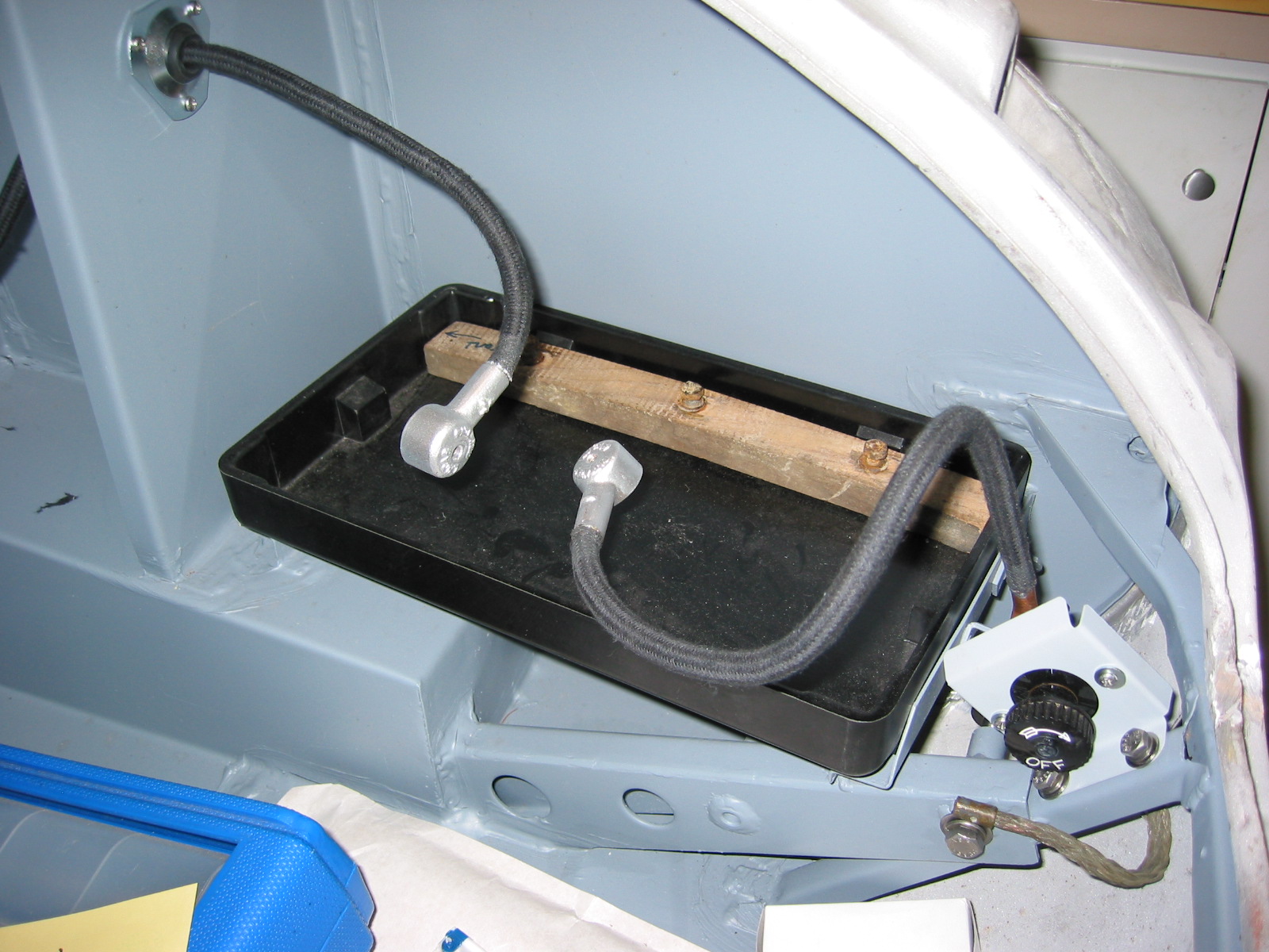
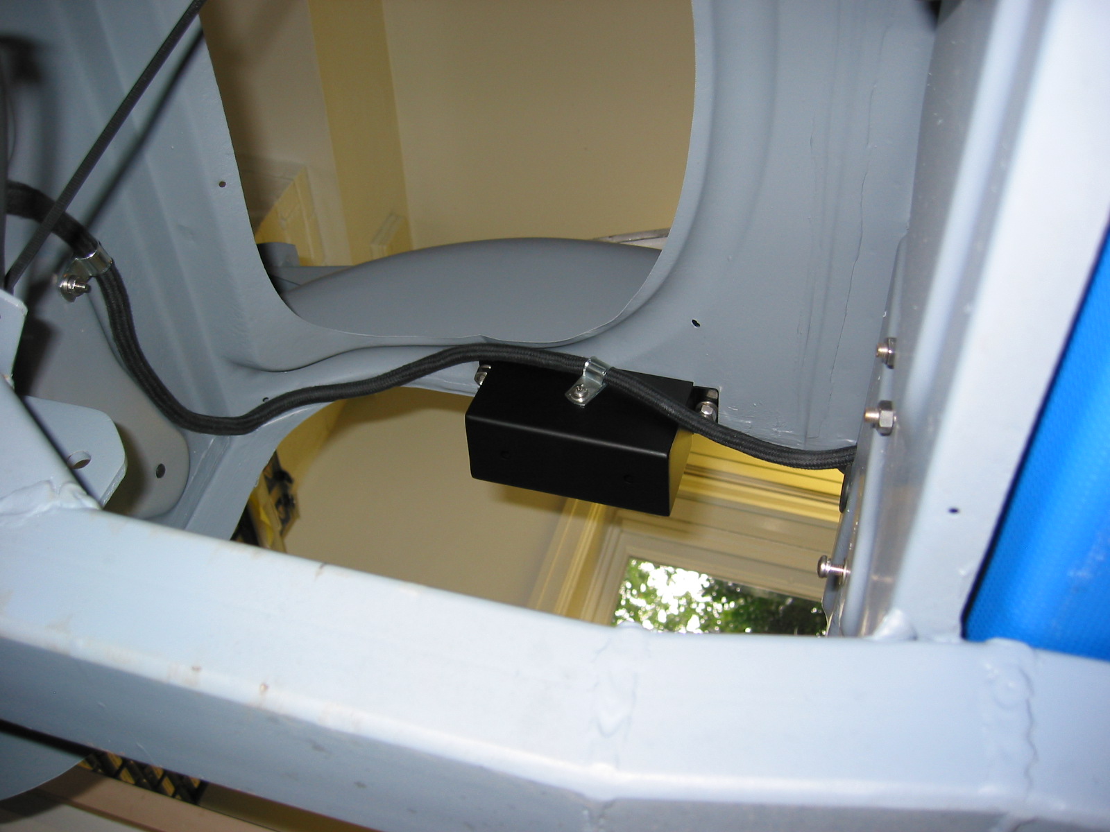
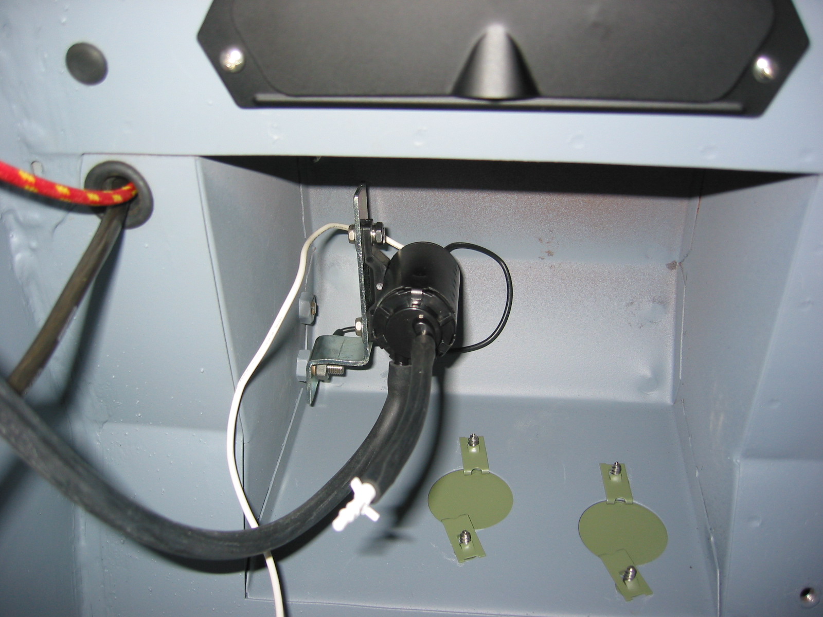
I mounted the pump in the interior in the right side pedal box space. At that location it is virtually impossible to see. I made a small bracket that allowed me to secure the pump to one of the 1/4” bolts that is used for the throttle shaft bracket if it were a RHD car. I did replace the 1/2” blanking hex bolt with a 1” bolt, giving enough length to fit the bracket.
Windscreen washer pump
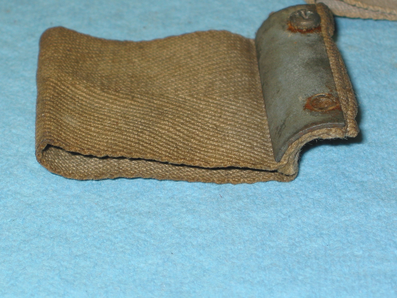
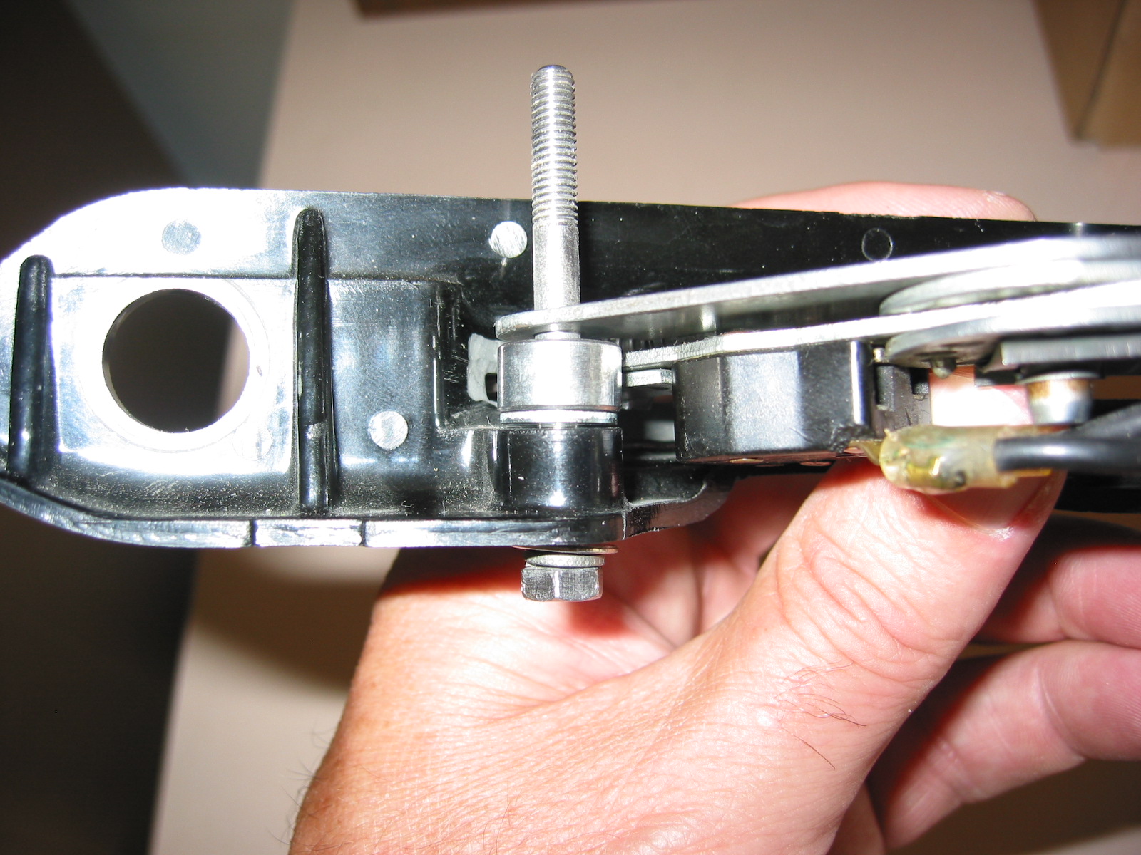
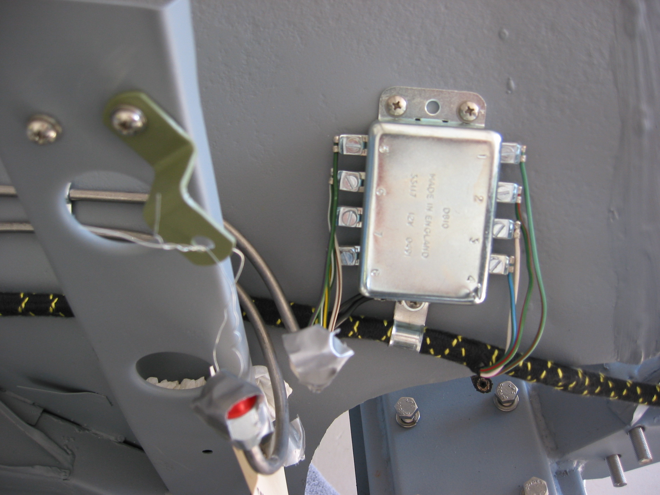
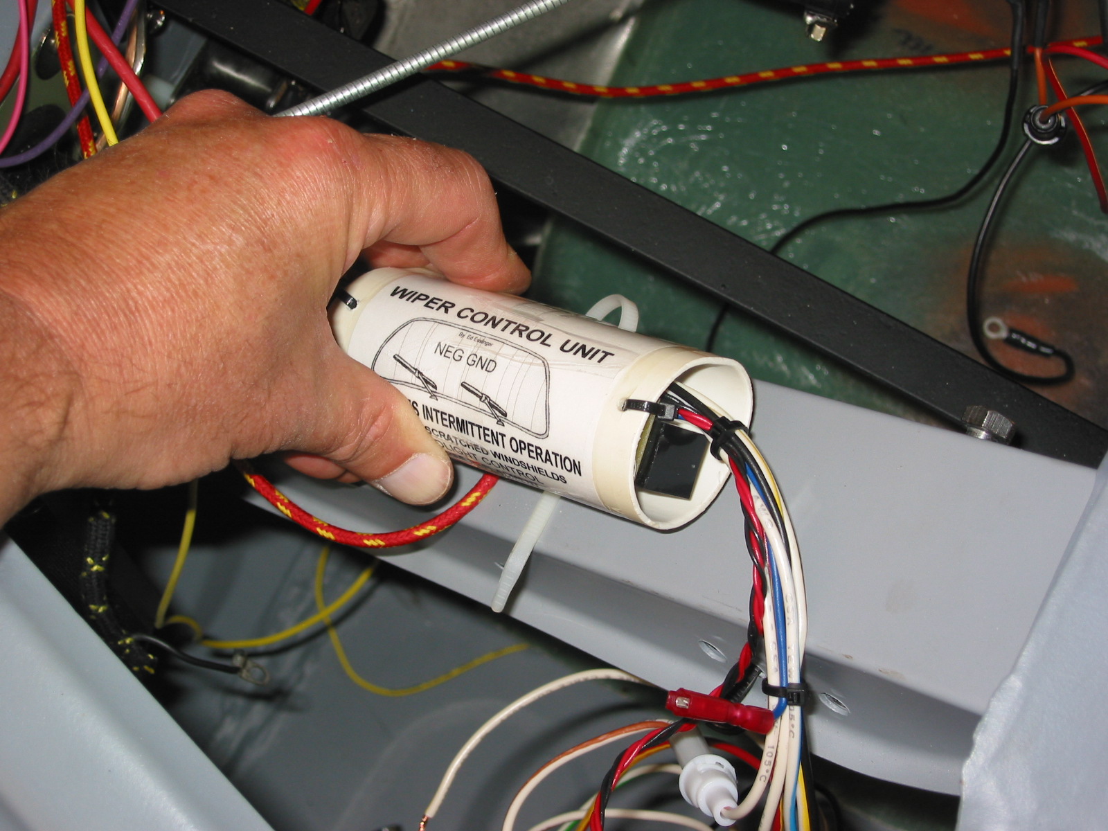
Intermittent Wiper Control – Ed Esslinger, a member of the TigerUnited club designed and built a wiper control unit to provide intermittent wiping of the windscreen and made them available for sale. edstiger@charter.net 334-774-5155.
The green wire TO the wiper motor must be disconnected so that the delayed 12V can be applied to it from the Wiper Control (WC) unit. Disconnect the battery.
Disconnect the black/green wire from the dash switch. Connect the white/yellow wire from the WC to the switch terminal where the black/green wire was removed.
Connect the red/yellow wire from the WC to the black/green wire that was disconnected from the switch.
Connect the black wire from the WC to the terminal on the wiper switch that already has a bleck wire, which must be left connected. (Black wire can be connected to any good ground point.)
Reinstall the wiper switch to the fascia.
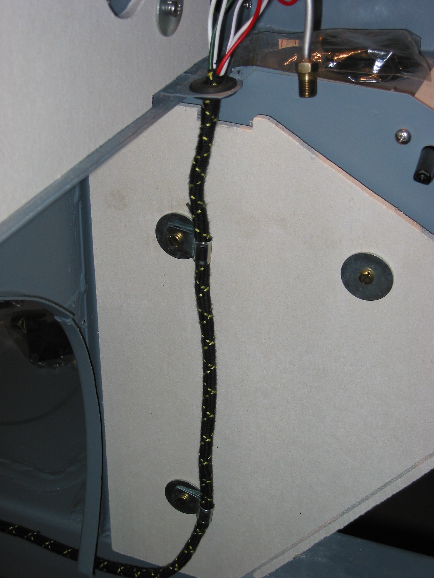
Route the long white/blue wire from the WC to the wiper motor. Connect the green wire from the motor to the white/blue wire.
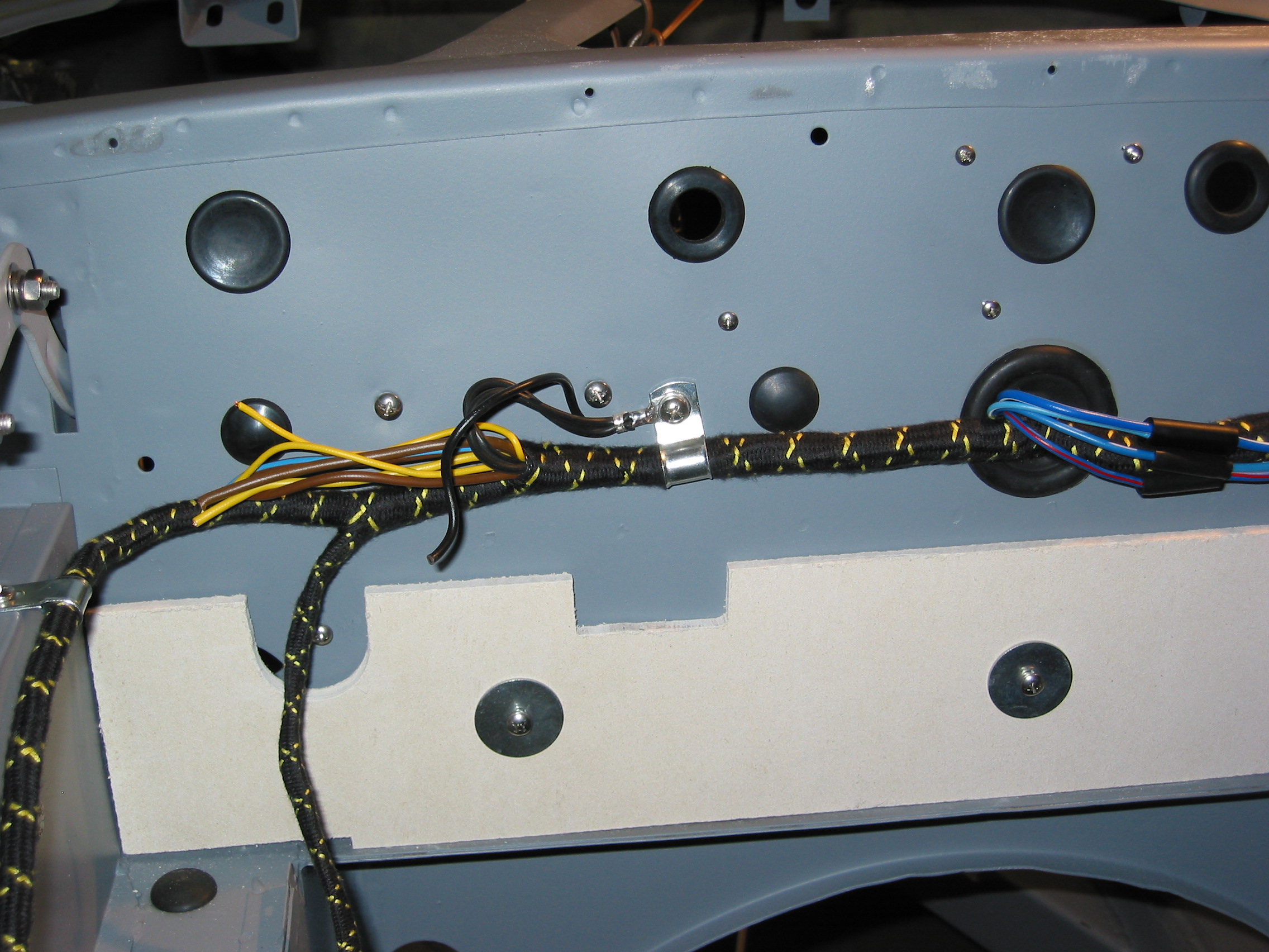
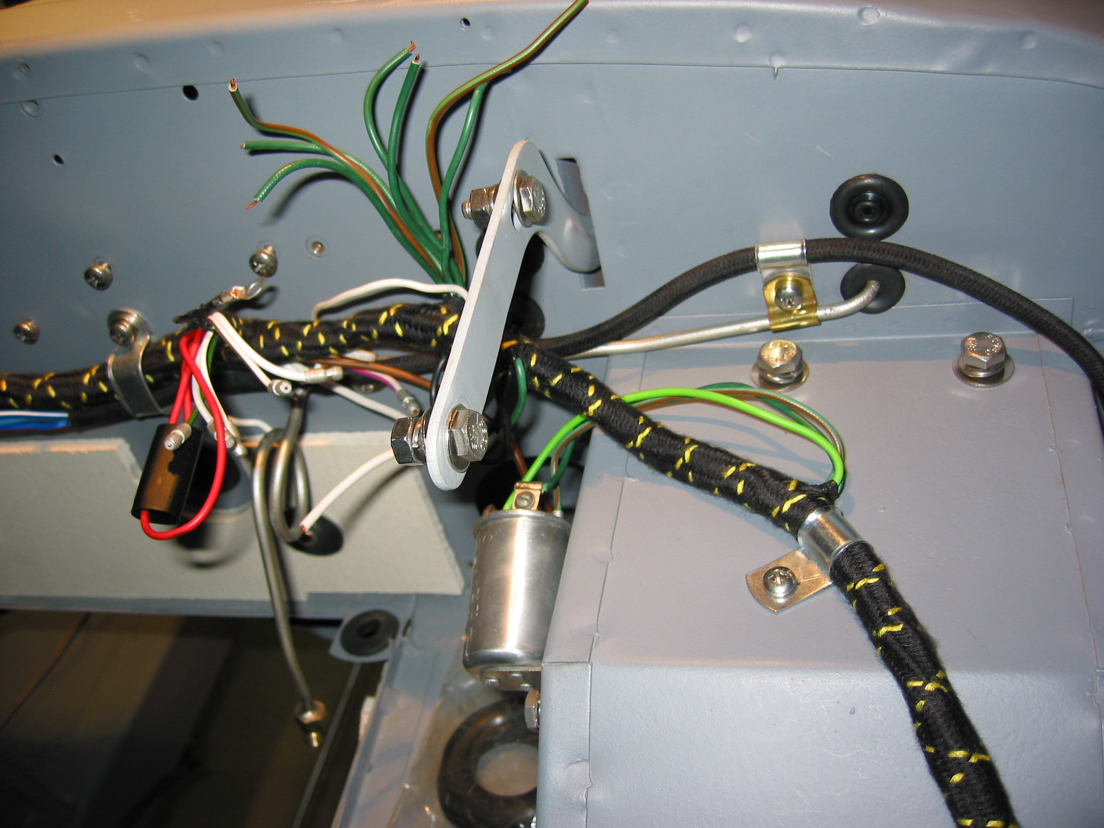
Route the long white/green wire and the white/brown wires from the WC through the grommet in the firewall. Connect the white/green wire to the fuse block terminal with the other green wires. (switched 12V). Connect the white/brown wire to the to the fuse block with the fused side – brown wires, this is the unswitched 12V. It may have purple wires attached to it.
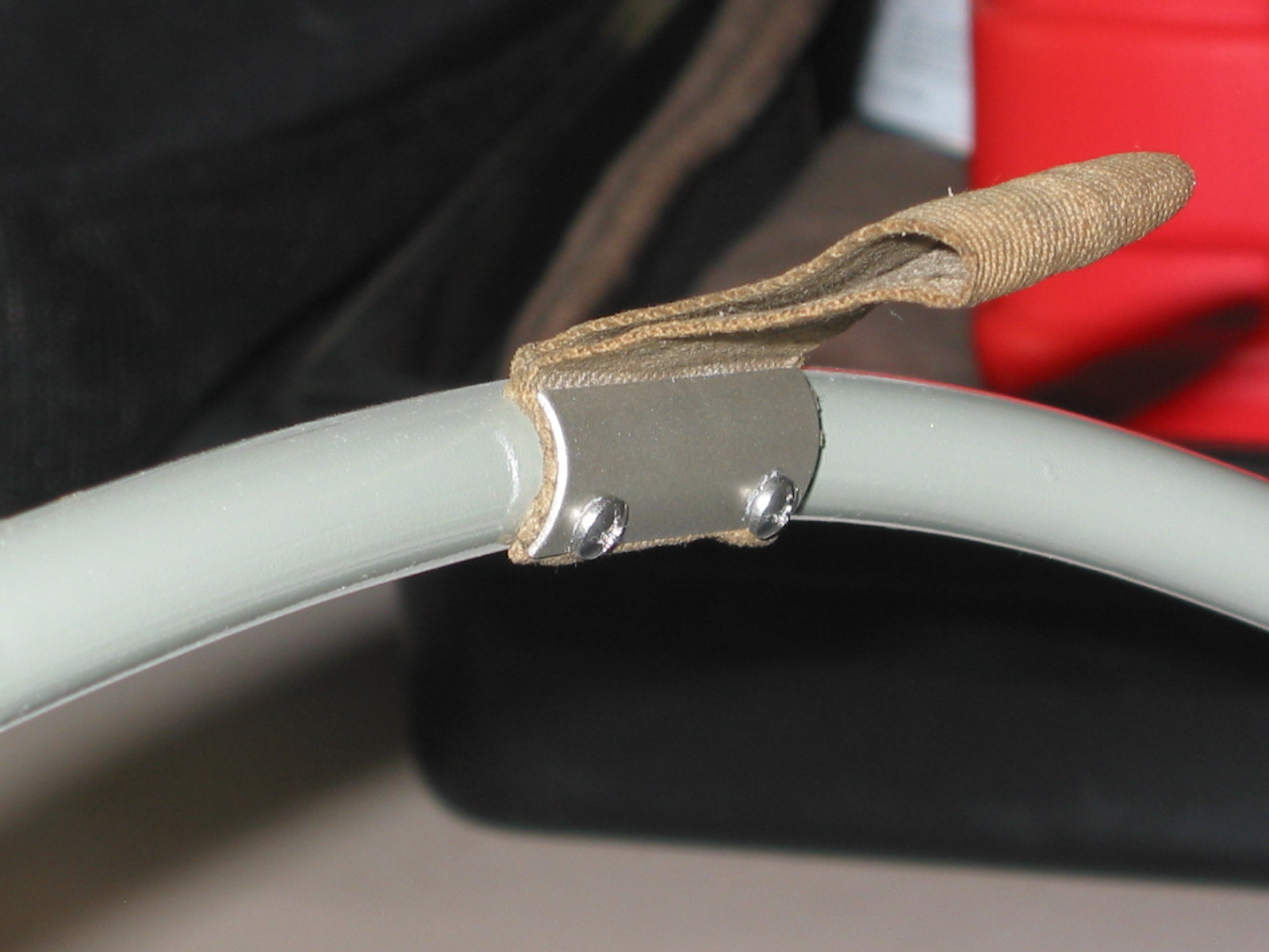
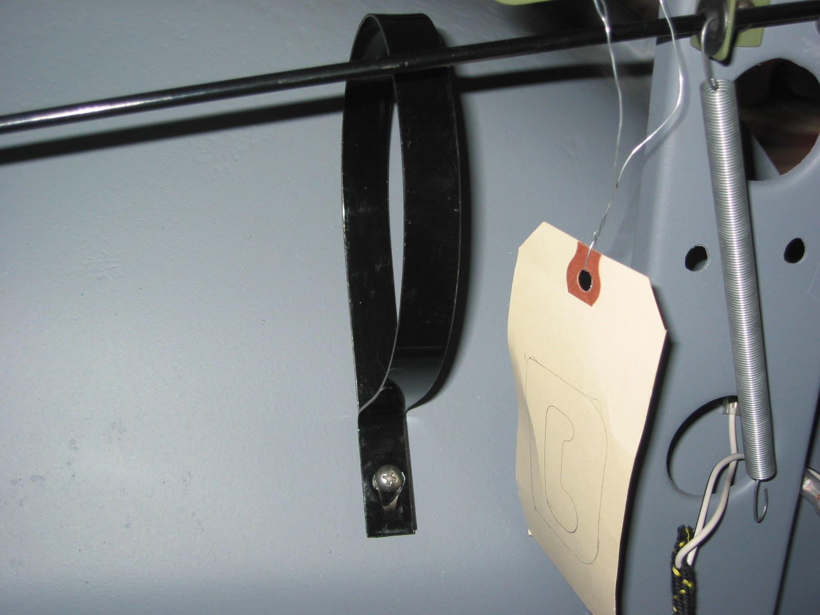
I then mounted the WC to the steering wheel bracket with a plastic tie strap.
Intermittent wiper 1
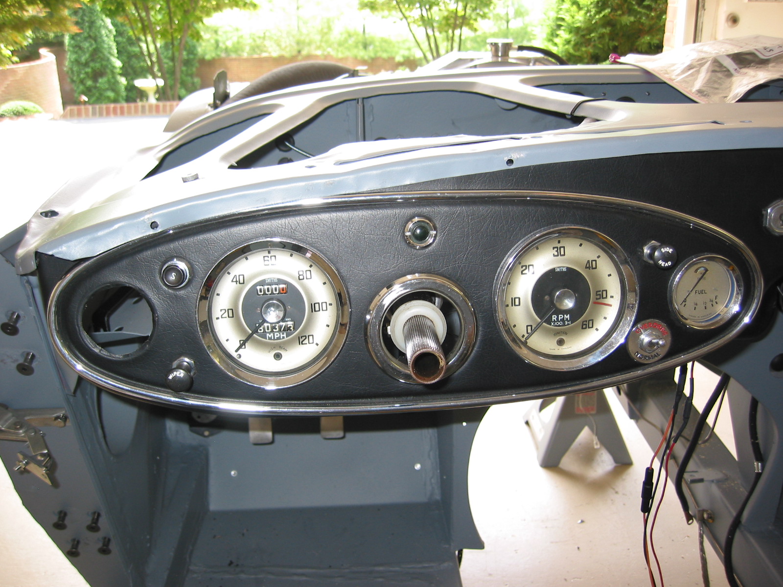
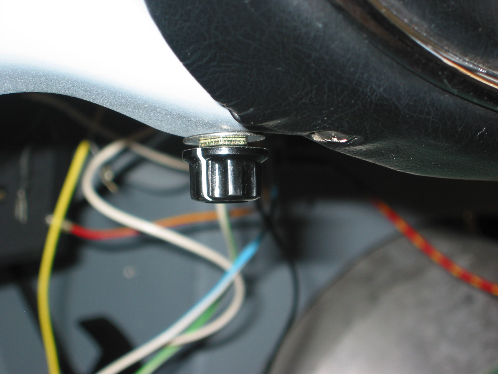
I mounted the remote interval control on the fascia bottom to the left of the wiper switch. Reconnect the battery.

Intermittent wiper switch 2
Intermittent wiper switch 1
Testing procedure
Wet the windscreen. Make sure the remote control and the wiper switch is turned off.
Turn the ignition on.
Turn on the wiper switch – wipers should work normally.
With the wiper switch on, turn off the ignition switch. Wipers should continue to run and park themselves.
With the wiper switch still on, turn the ignition back on. Wipers should not operate.
With the ignition still on, turn off the wiper switch for a few seconds. Place the wiper switch on. Wipers should now work normally.
With the wiper switch on, rotate the remote interval clockwise. After a few seconds the wiper will operate in the intermittent mode, and can be adjusted to run from a few seconds to about 60 seconds.
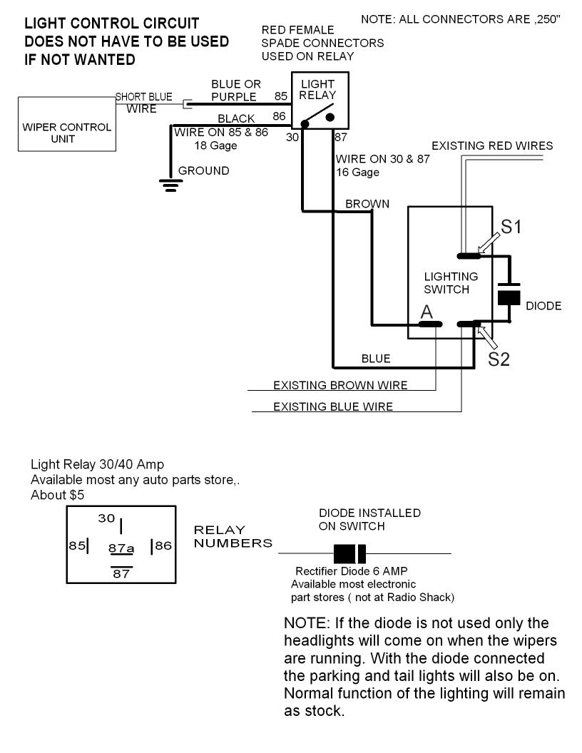
Controlling the Headlights when the wipers are onEd’s kit also provides a connection to permit the headlights to be turned on when the wipers are turned on. Directions for the relay are provided below:
100-6 headlight control_1
February 12, 2005
More Modifications for Comfort
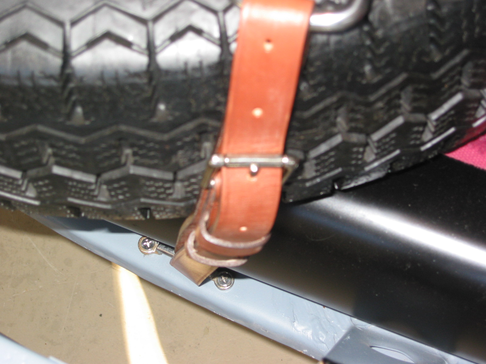
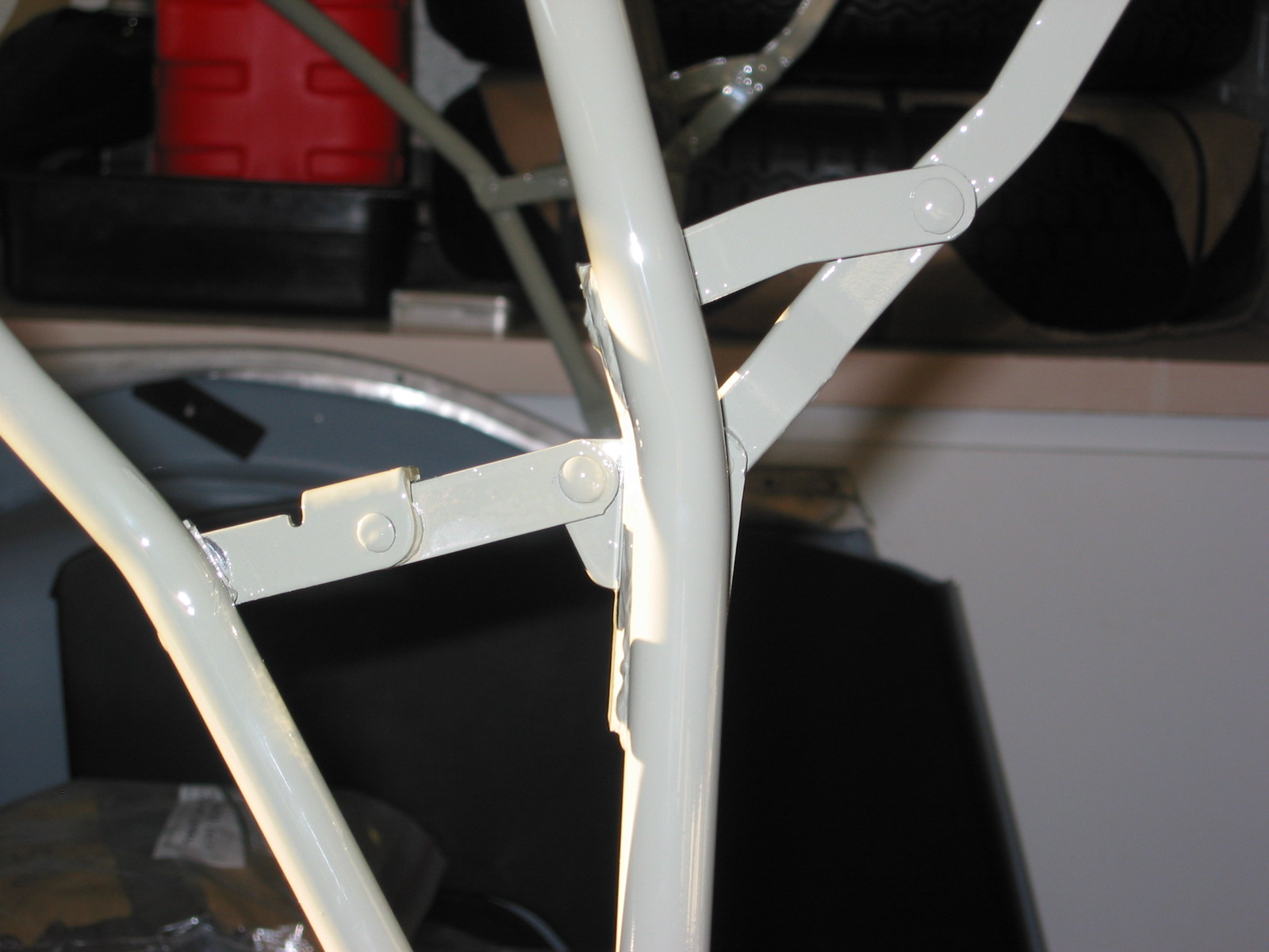
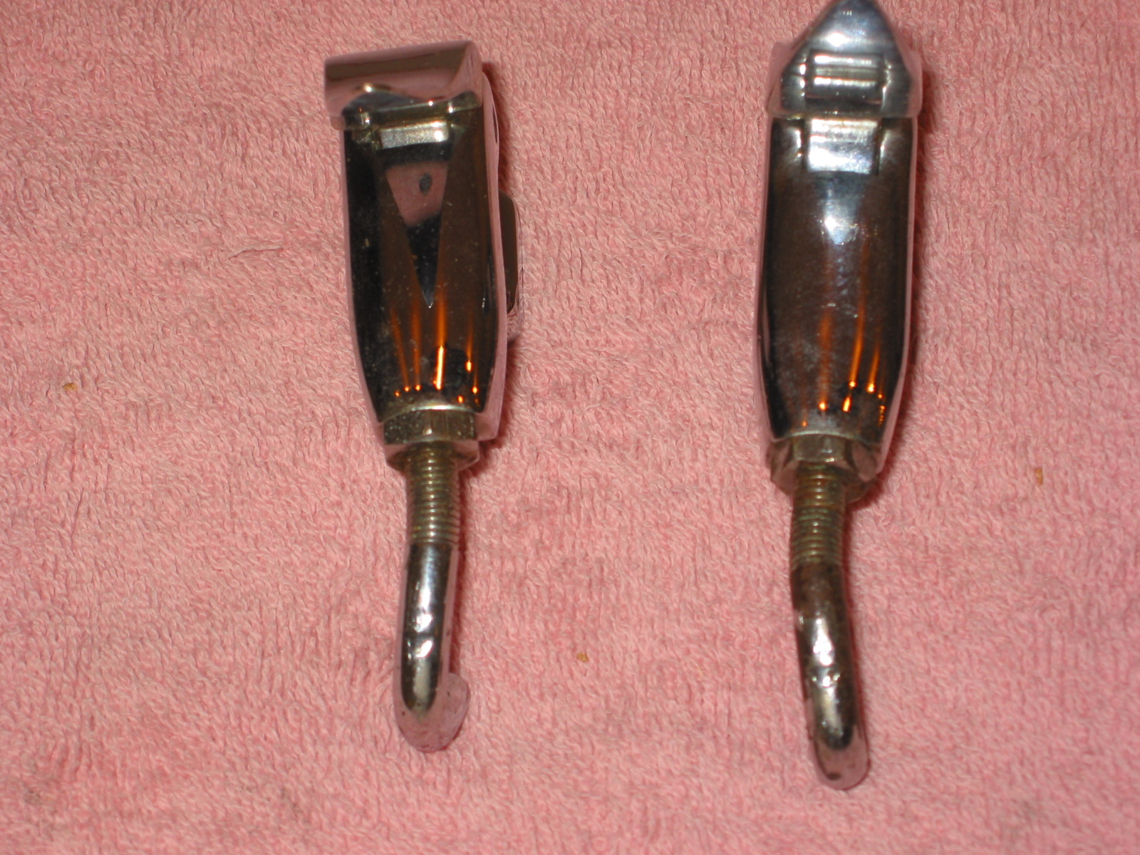
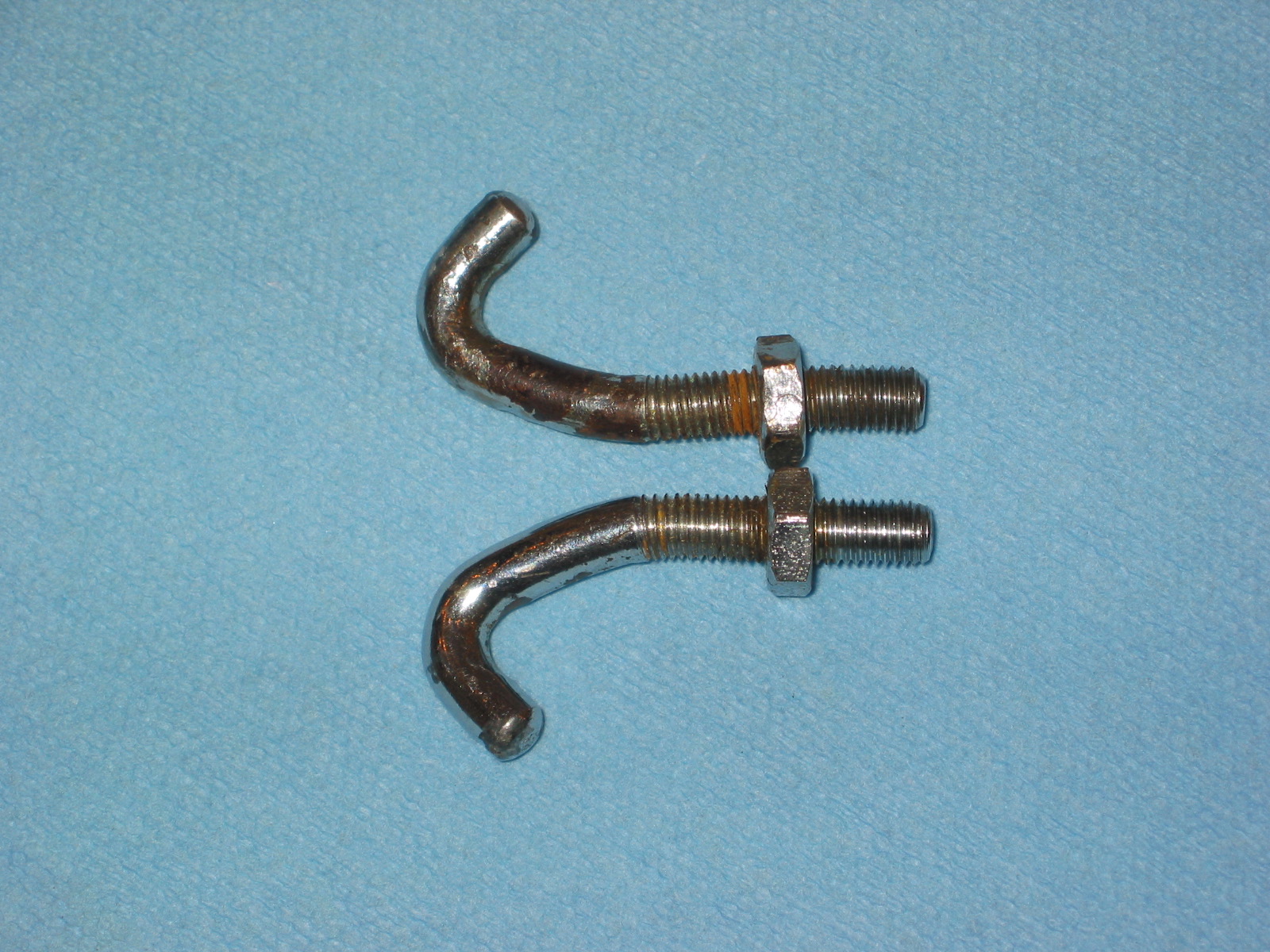
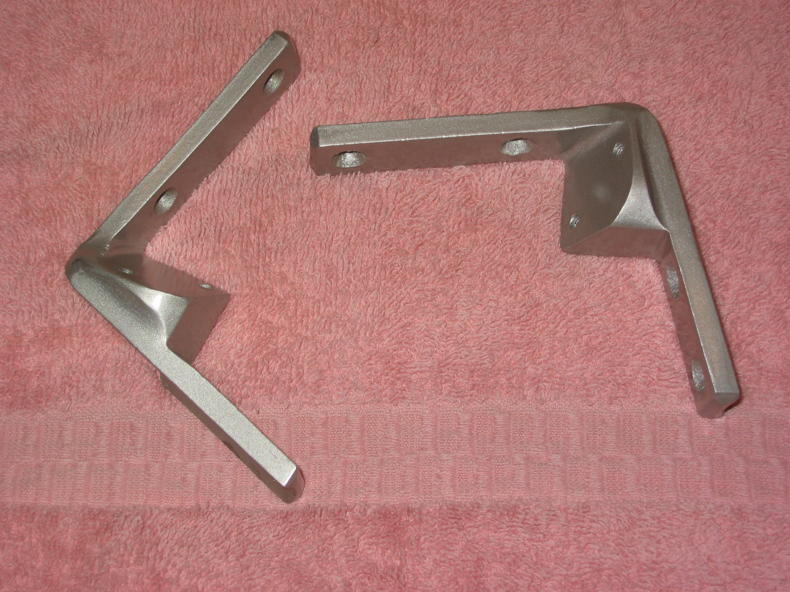
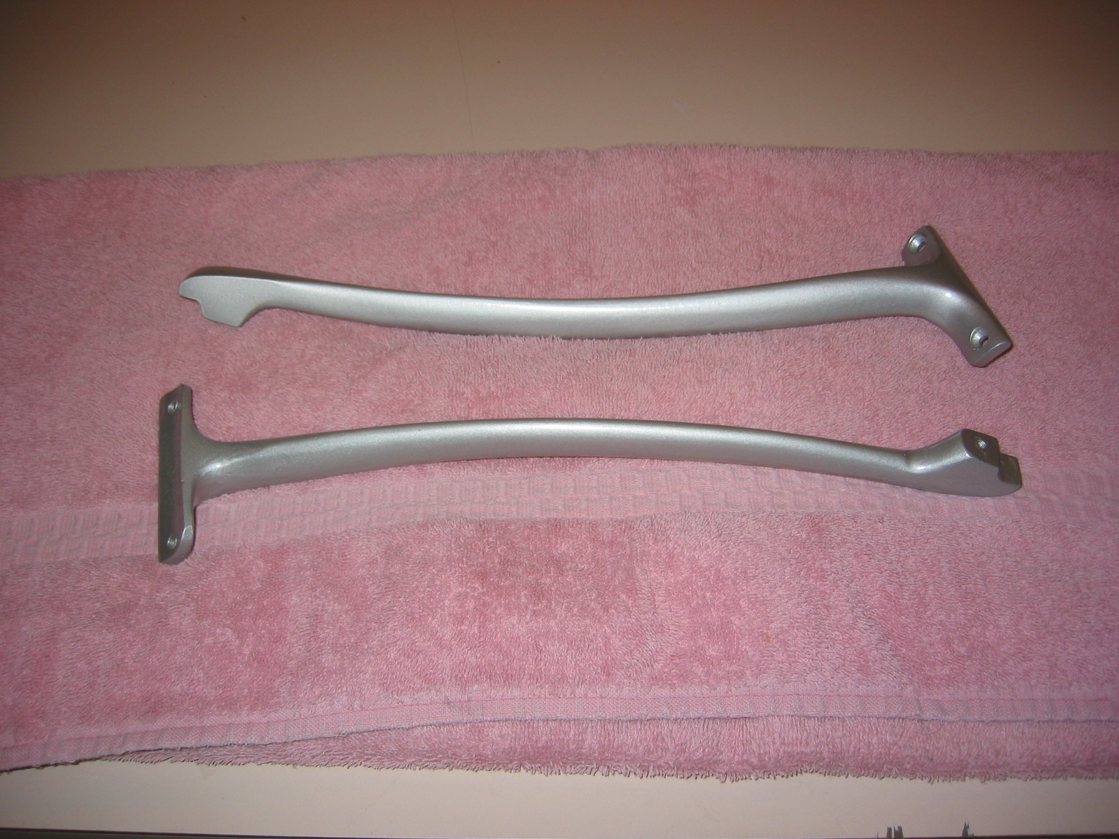
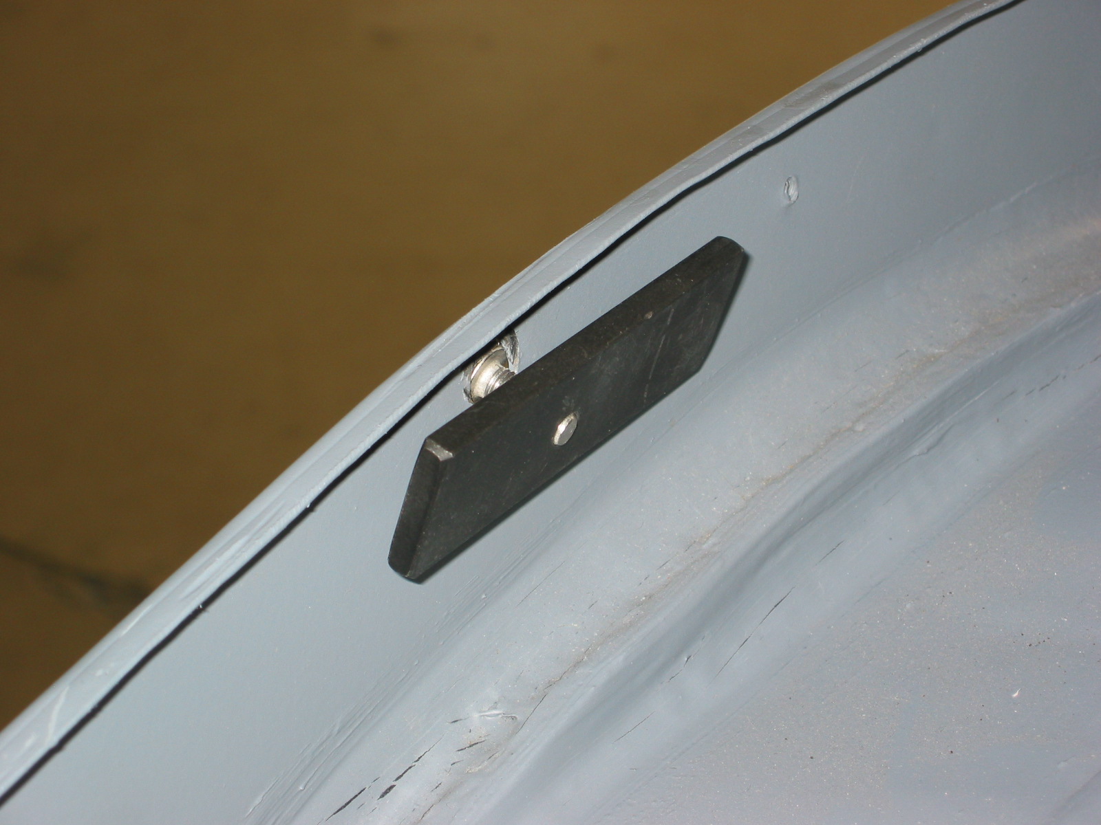
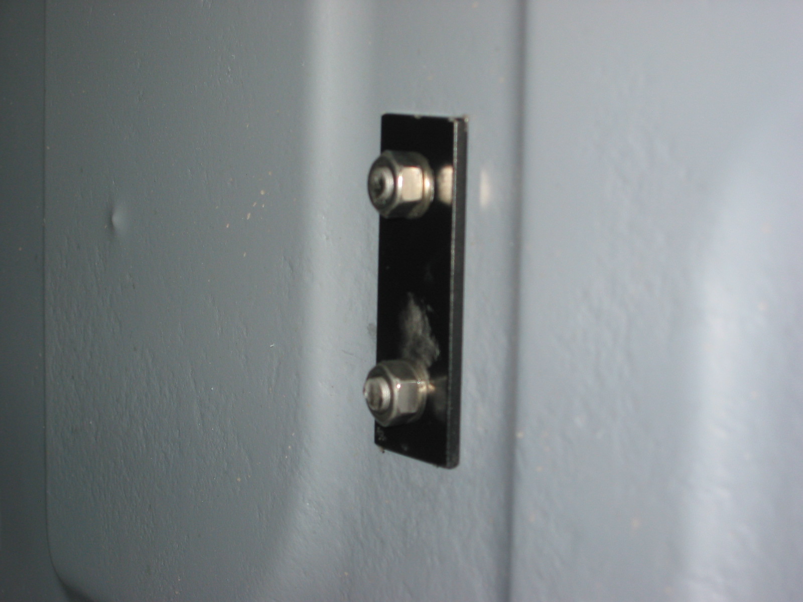
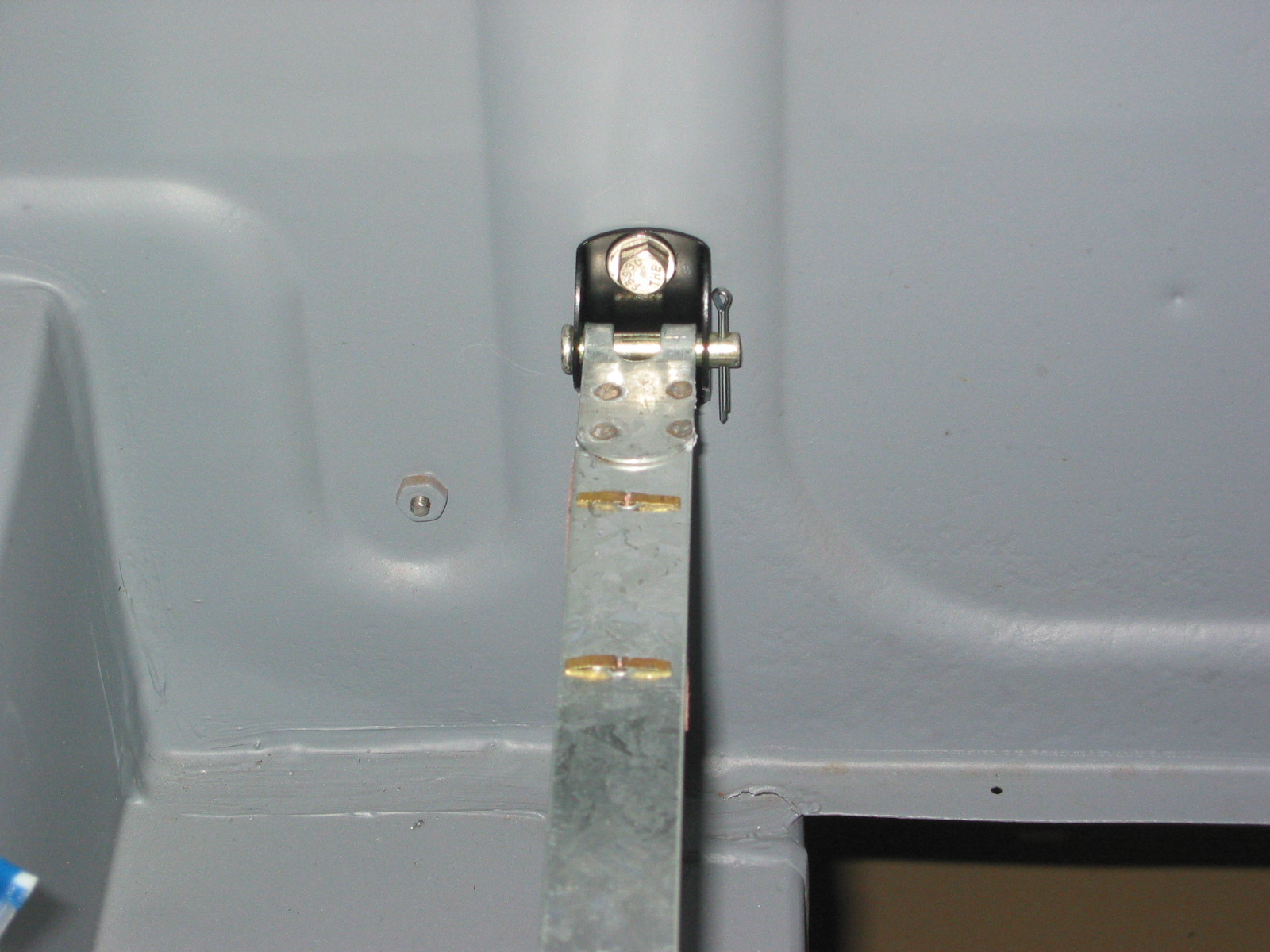
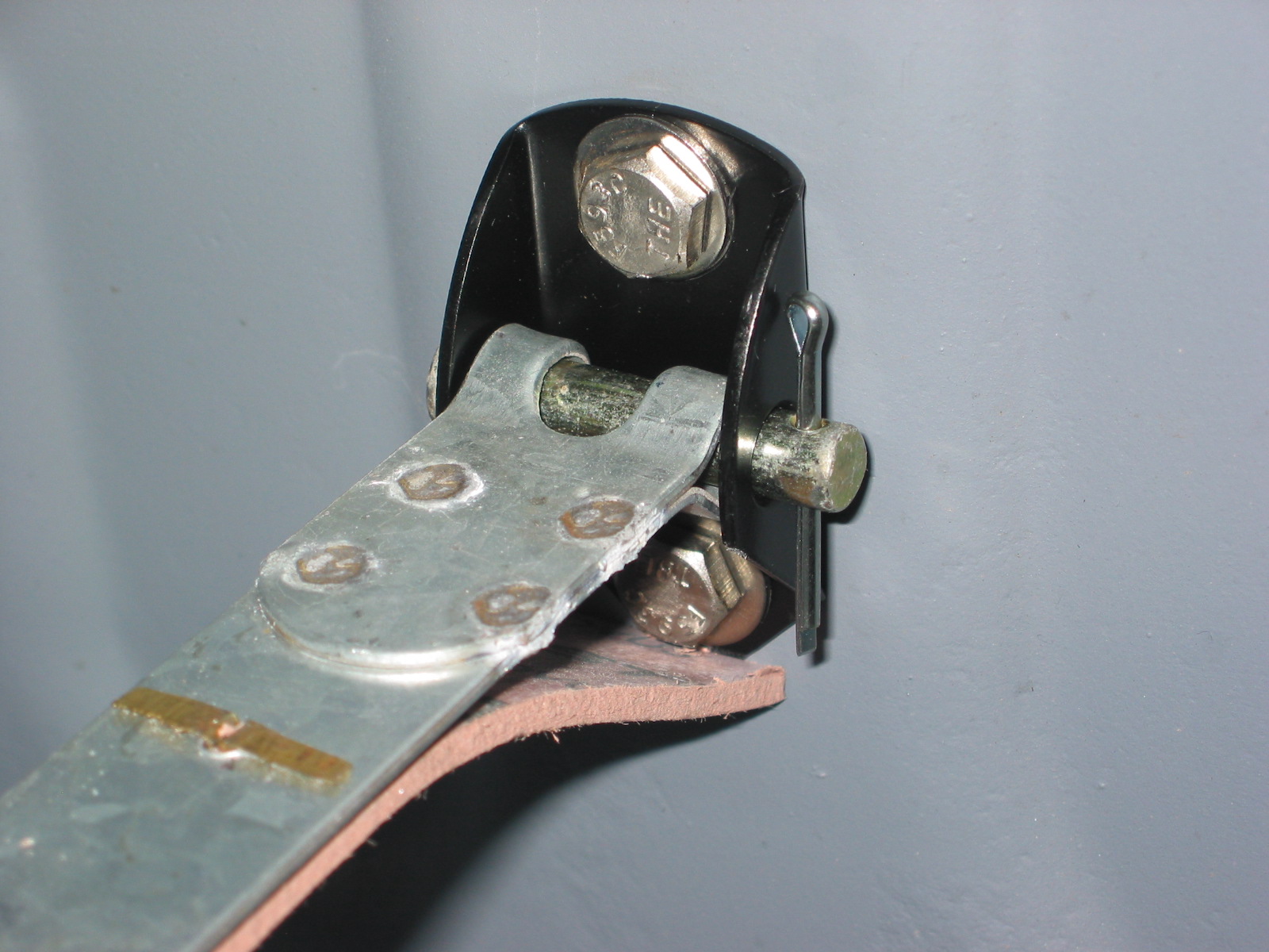
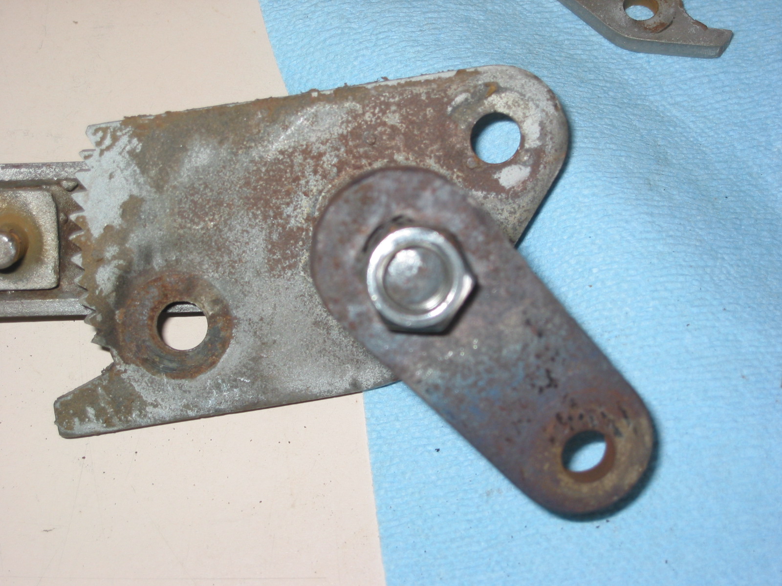
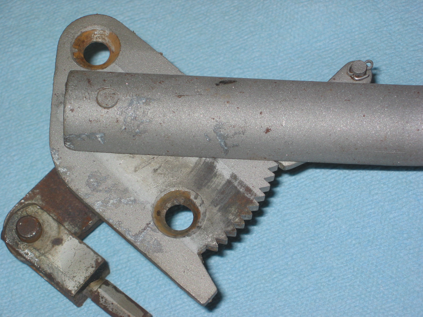
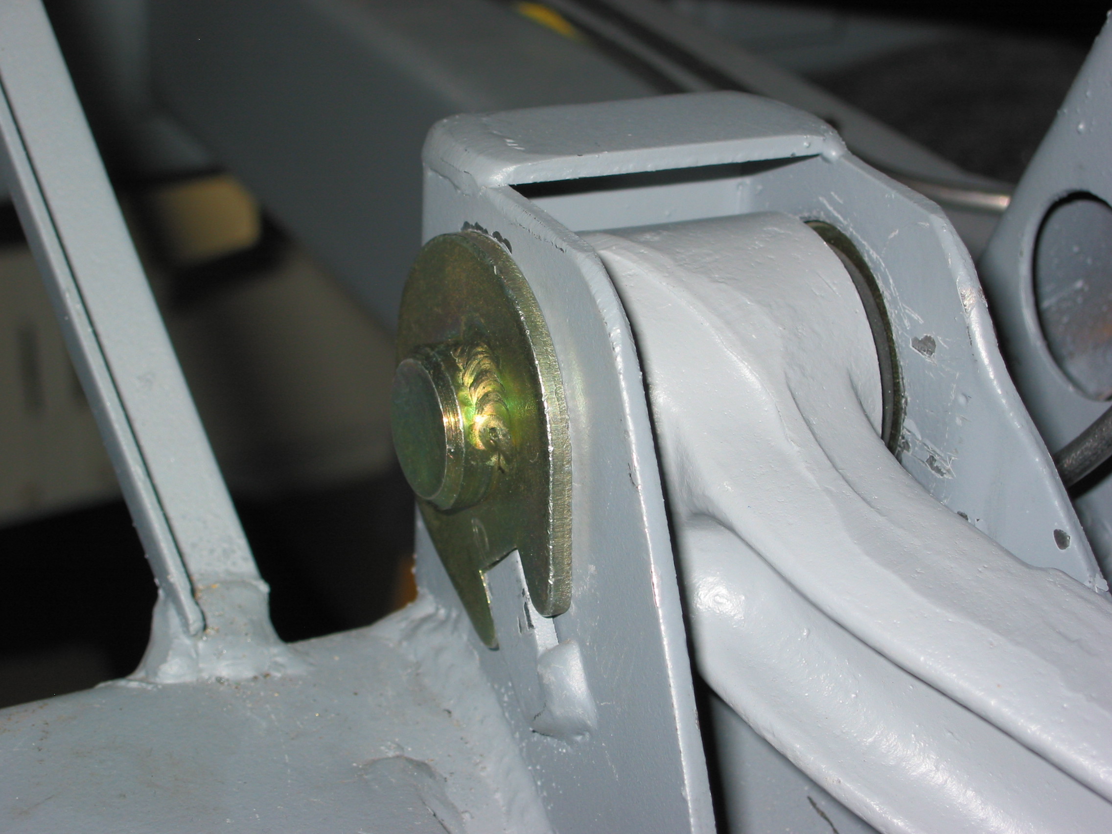
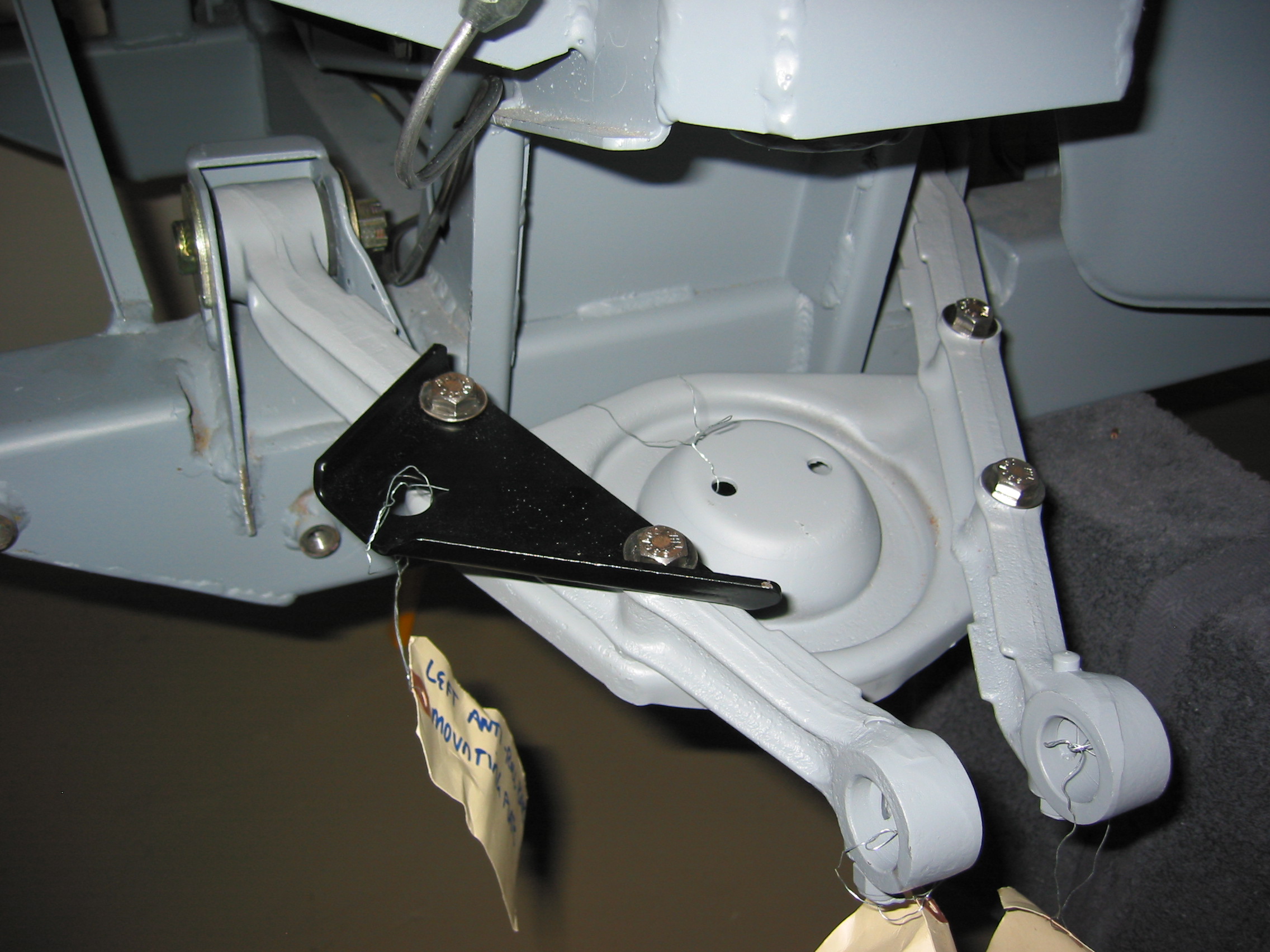
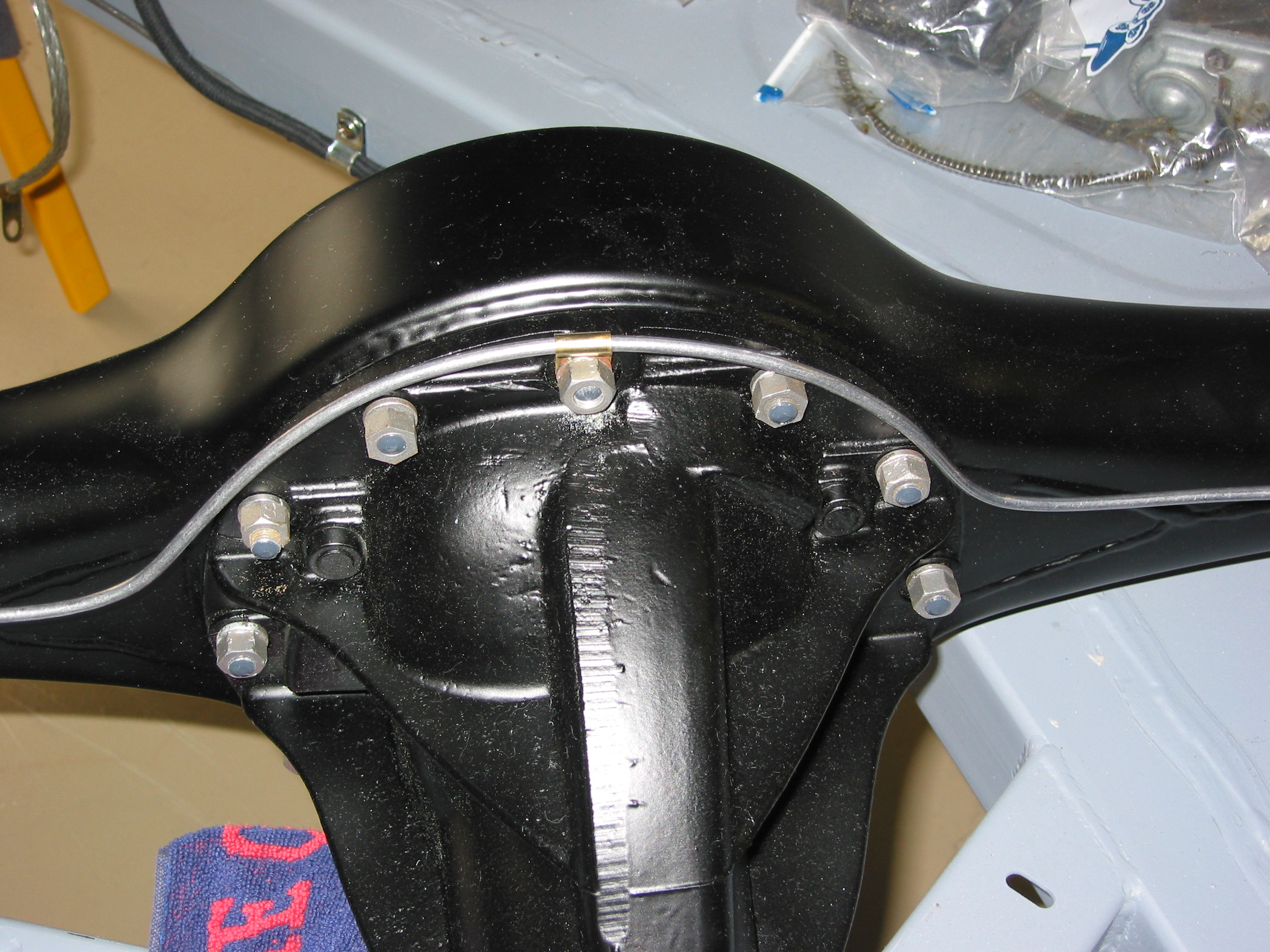
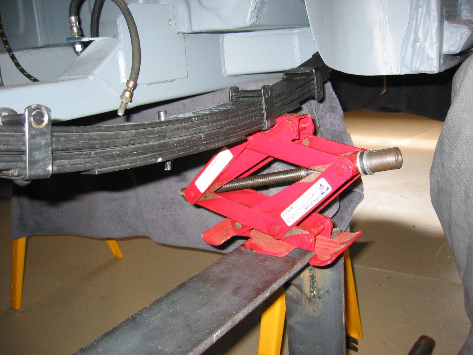
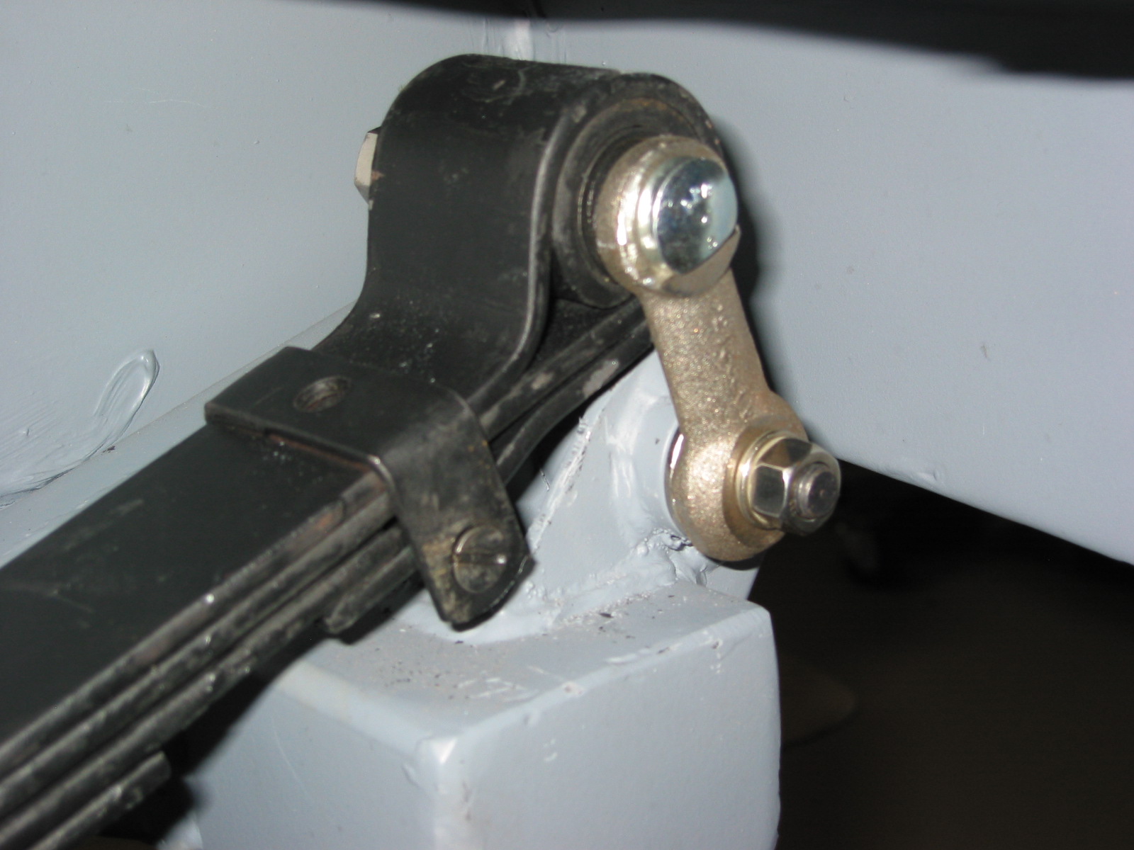
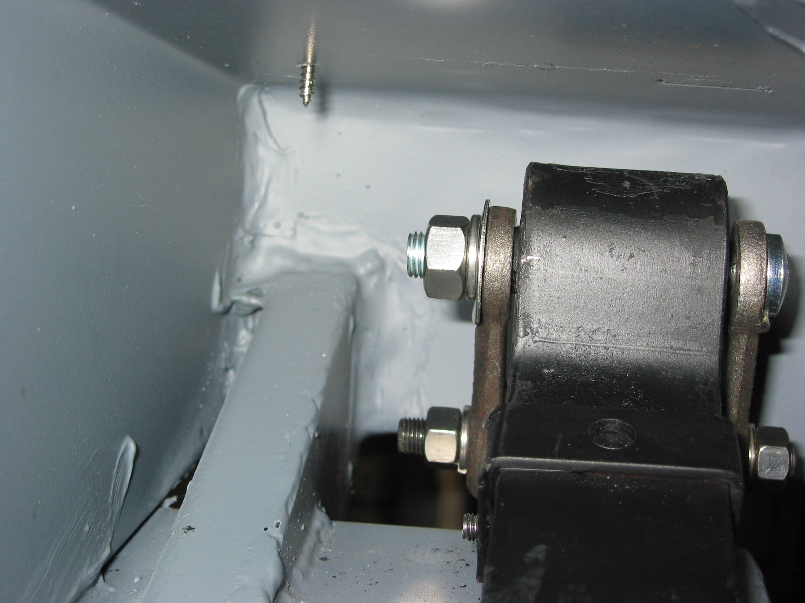
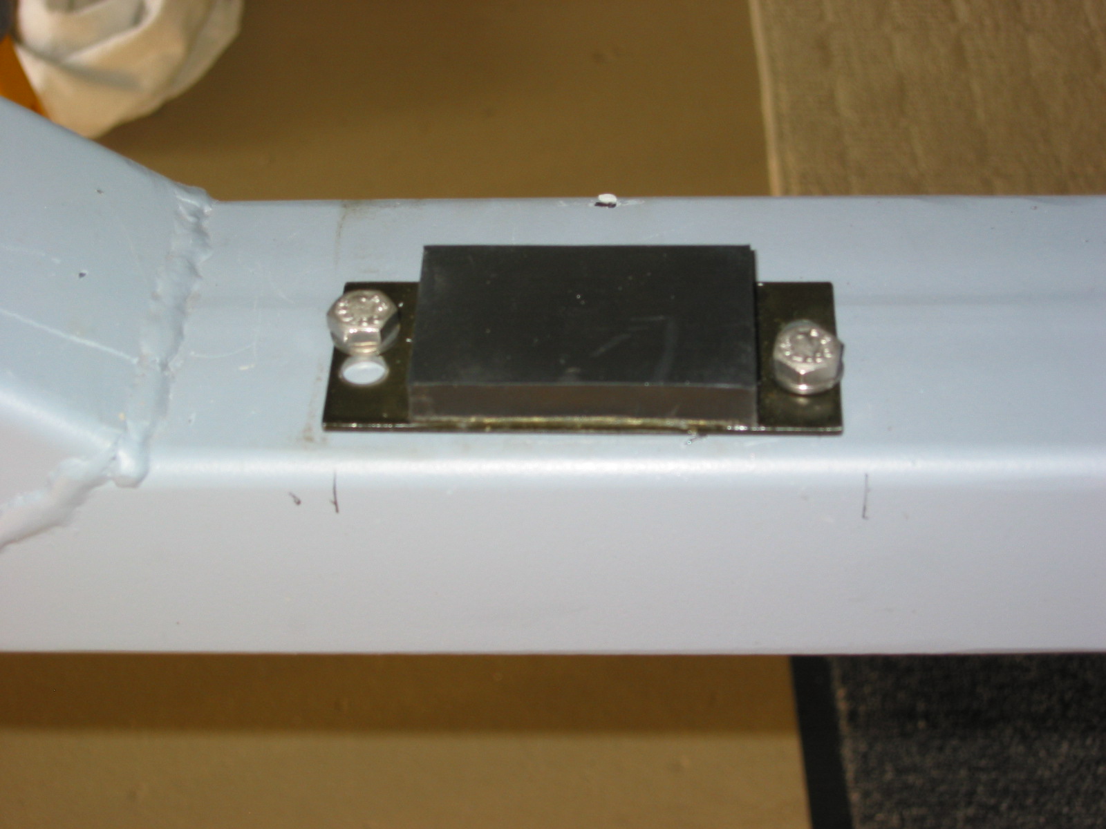
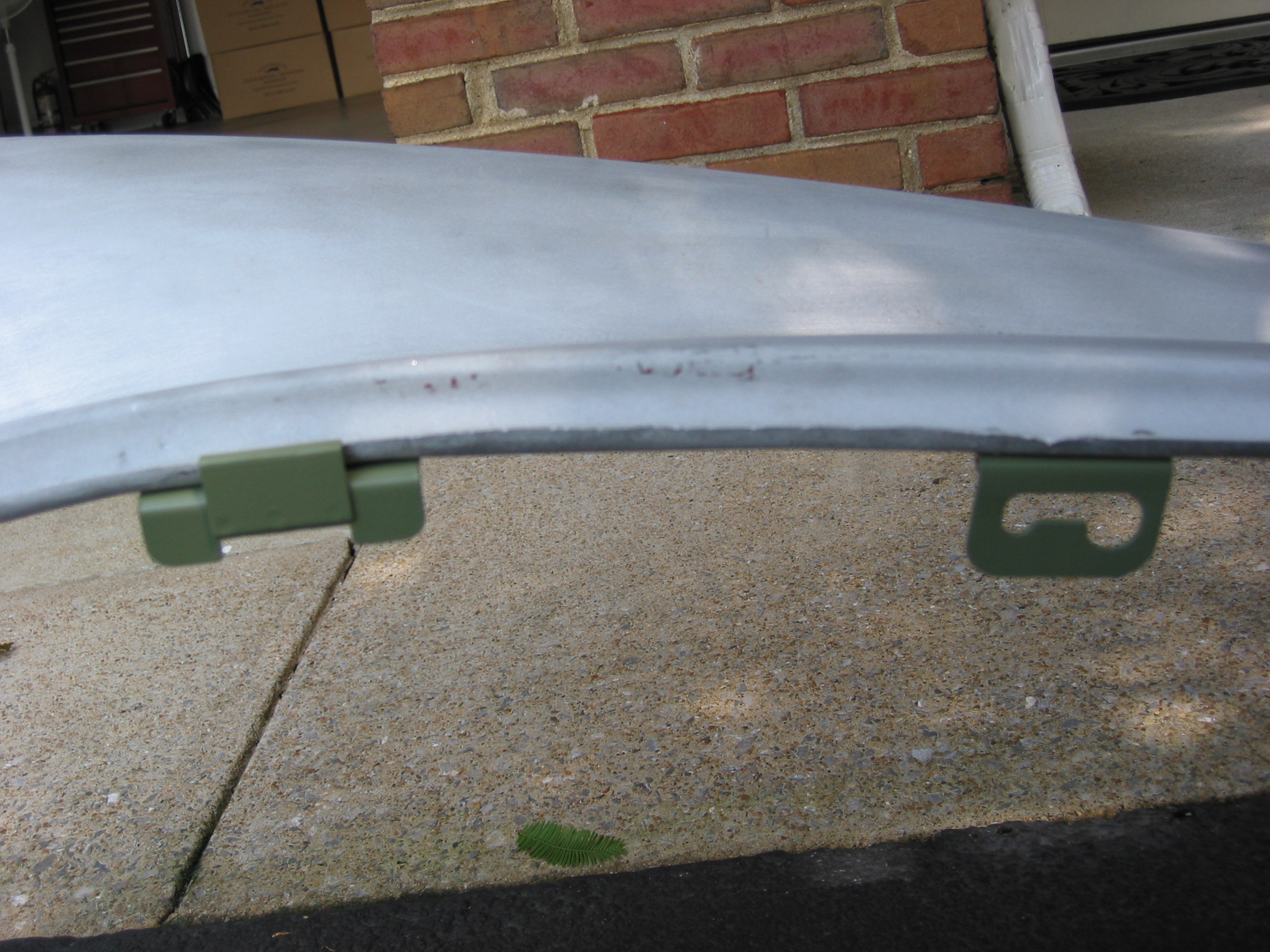
Driver’s Seat Angle Adjustment – I borrowed an idea from someone on the healey list-serve to make driving the 3000 a bit more comfortable for a person over 6 feet. I purchased 4 “couplers”, 1/4”-28 x 7/8.”
On the most forward (closest to the steering wheel) studs on the seat rail mechanisms, I simply screwed the coupler onto to the stud. After the seat is in place the coupler is secured with 1/4” – 28 x 1/2” hex bolt (flat and lock washer).
On the middle stud, I cut the coupler so that is was approximately 1/2” long. I then cut off the stud on the seat rail so that it was only about 3/8” long. I then screwed the coupler onto the shortened stud and secured it to the seat frame with another 1/4”-28 x 1/2” hex bolt.
Finally, the third seat rail stud is left as is and the seat frame is attached secured with a 1/4”-28 nut with washers.
Seat Rail riser 2
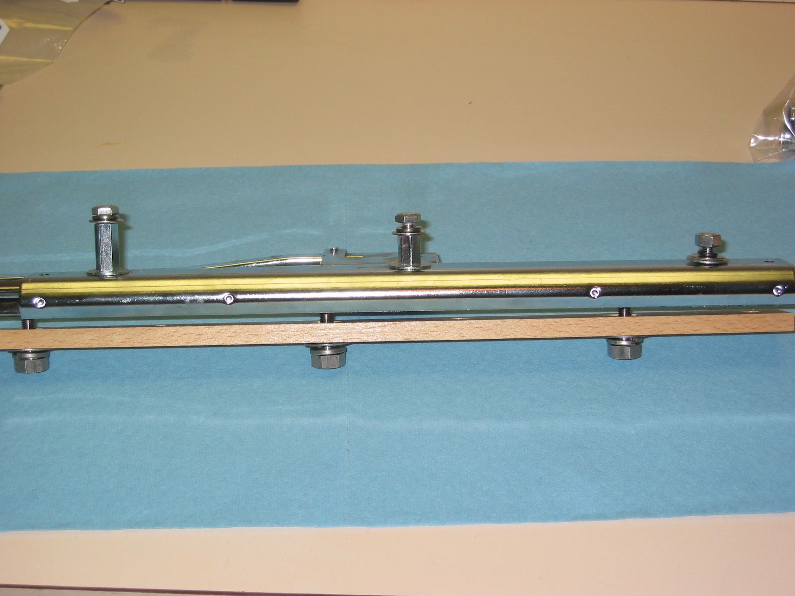
Seat rail Riser 1
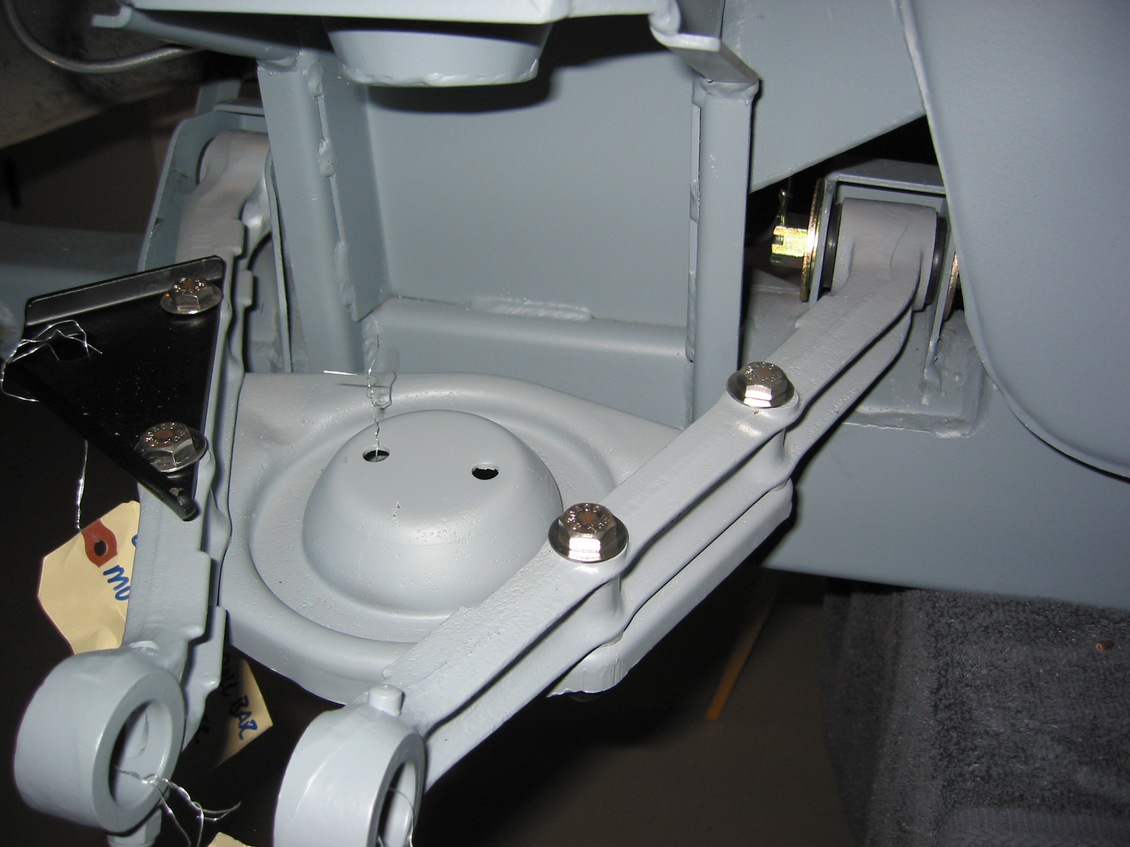
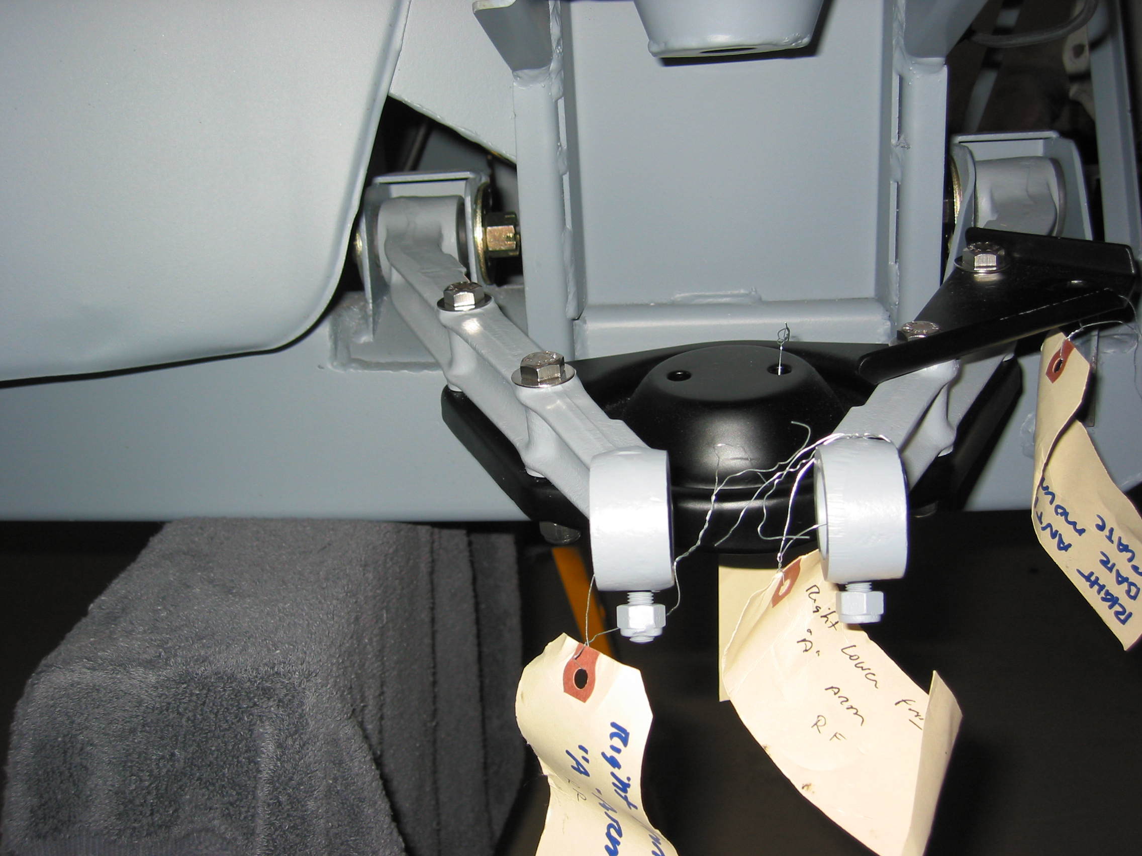
This modification slightly tilts the driver’s seat to the rear providing a little extra shoulder/arm reach to the wheel. I found the new position more comfortable. I decided against the modification for the passenger seat fearing that it might cut leg blood circulation unnecessarily. The visual appearance is only slightly different and probably only noticed by those who knew what was done.
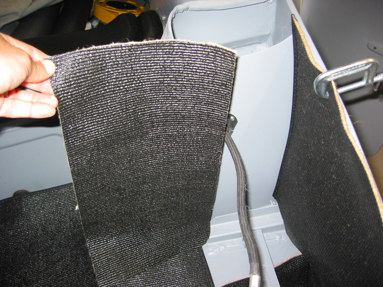
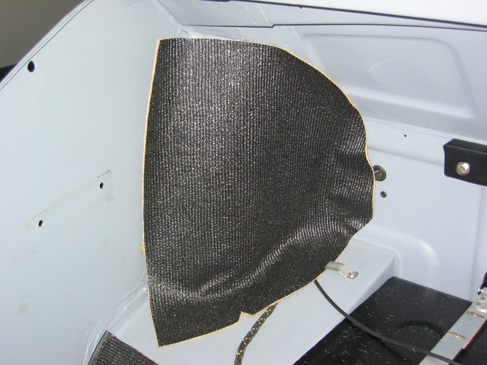
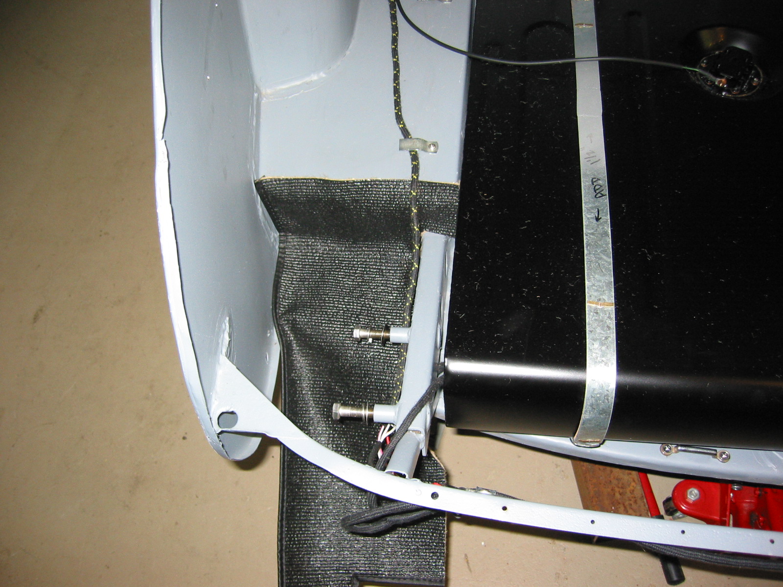
Carpet Installation
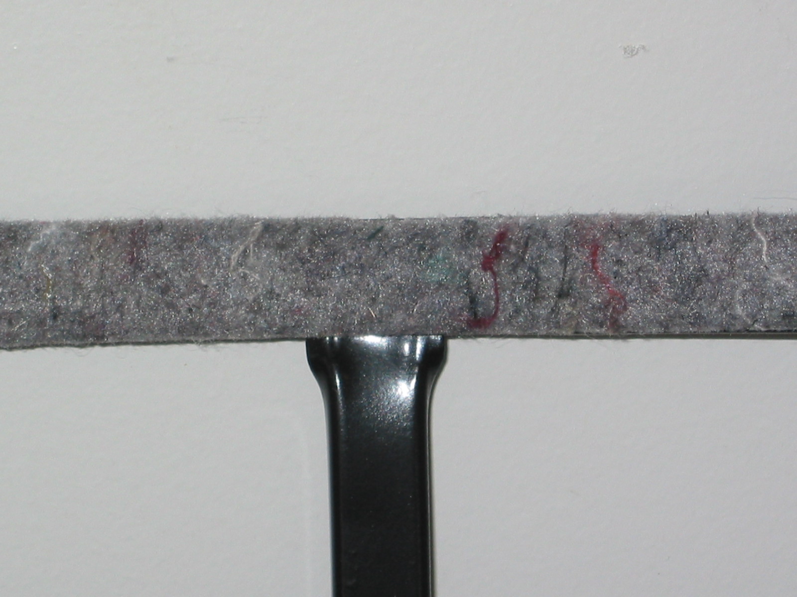
I received my Wilton Wool carpet from Heritage Upholstery and Trim. Everything looked great – very high quality. However, I was disappointed that the light beige carpet color was not exactly what I was looking for. I have decided to switch colors and will order black carpet for an all black interior.
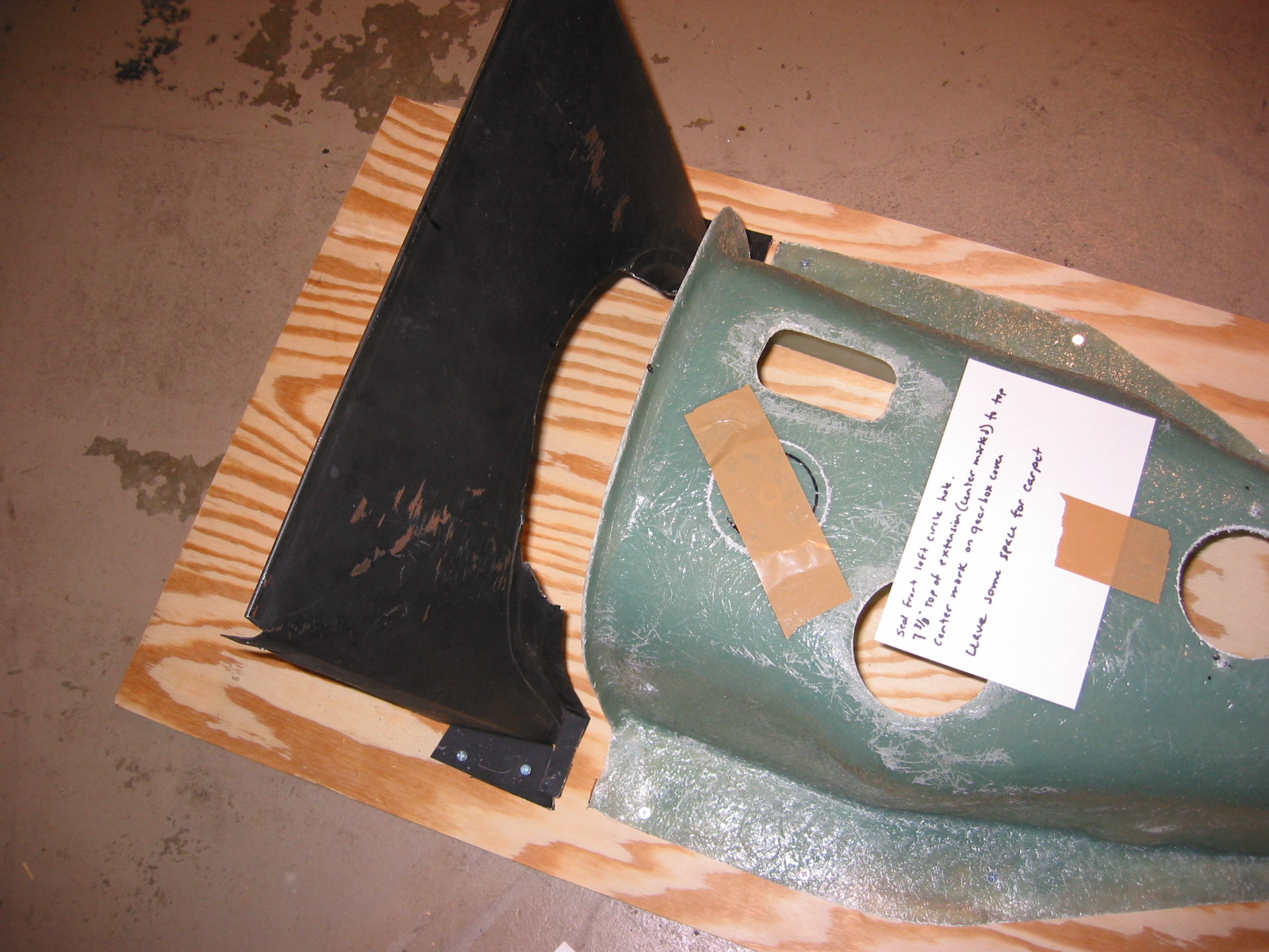
Although I wanted to go ahead an install the snaps on the floor boards and the gearbox cover before the car was painted. I decided to wait until final assembly. I really didn’t want to position the larger floor mat pieces until the footbox and siderail pieces were glued in place to insure the proper overlap and fitting in general. Since I cannot do the gluing of the smaller pieces until final assembly, I will just wait on this little project.