Heater
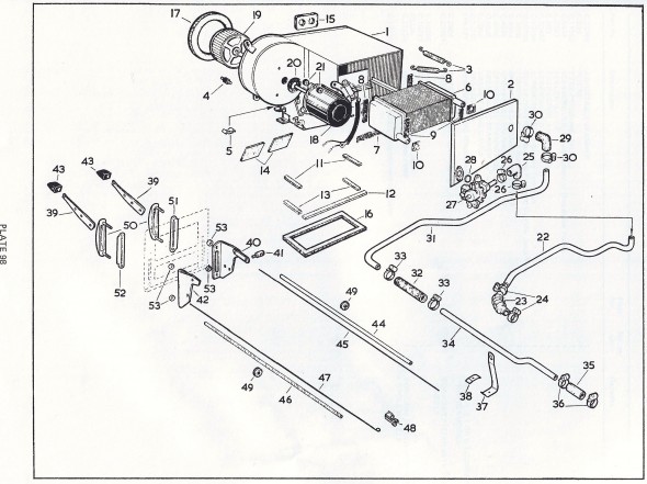
The heating and ventilating equipment consists of a heating element and an electrically driven fan mounted on the engine side of the scuttle. Air from the heater unit is conducted to a built-in duct situated under the instrument panel, to the rear compartment via twin pipes, and to vents at the bottom of the windscreen to provide demisting and defrosting. Either fresh air or air from the interior of the car can be introduced into the system at the will of the driver. FRESH AIR is introduced into the system by opening the scuttle ventilator and switching on the fan. Air from the interior of the car can be RE-CIRCULATED by closing the scuttle ventilator and switching on the fan.
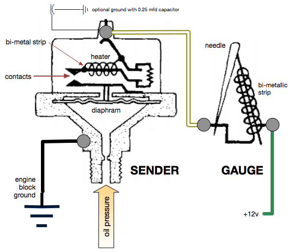
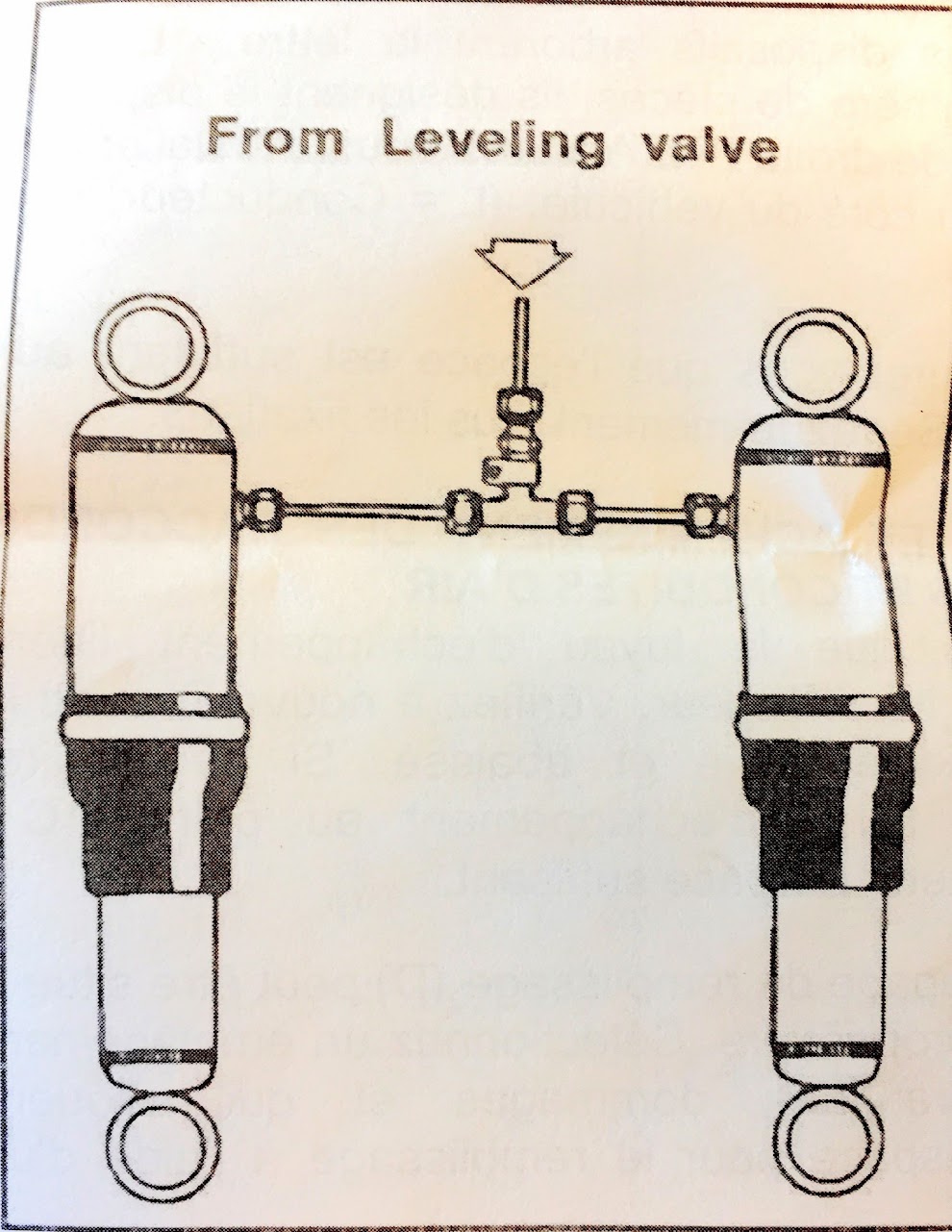
Heater Schematic
Heater Operation
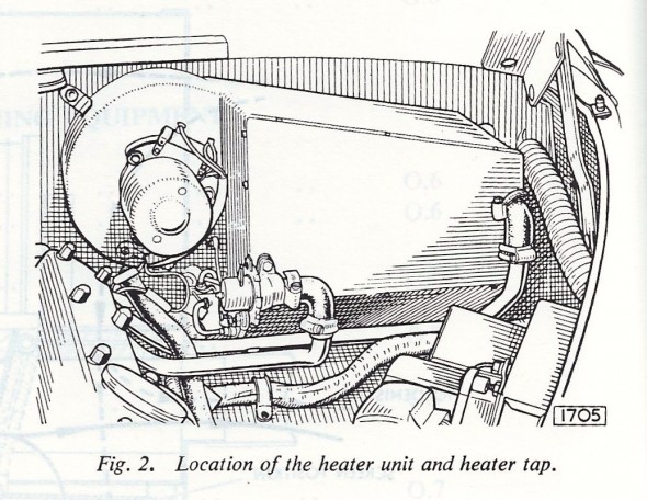
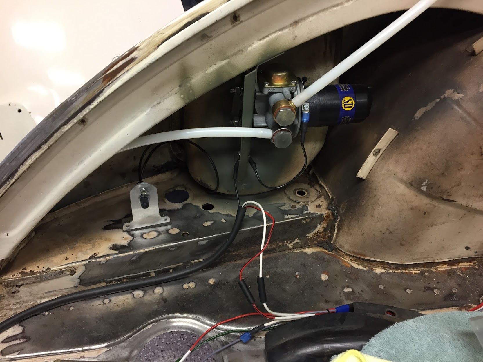
Heater in Engine Bay
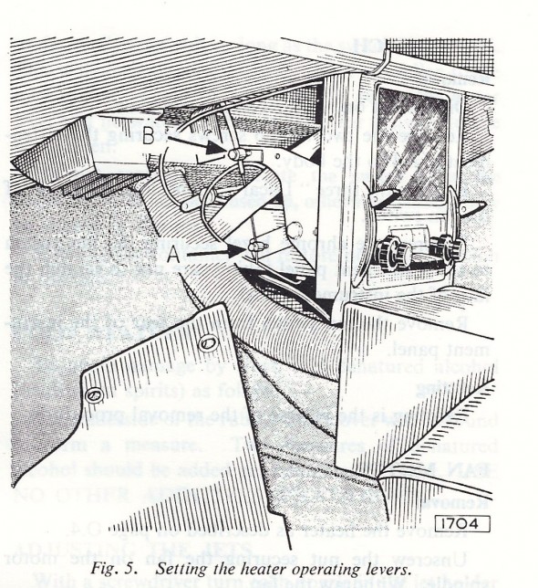
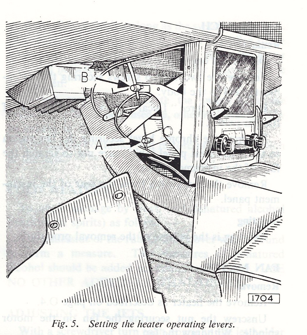
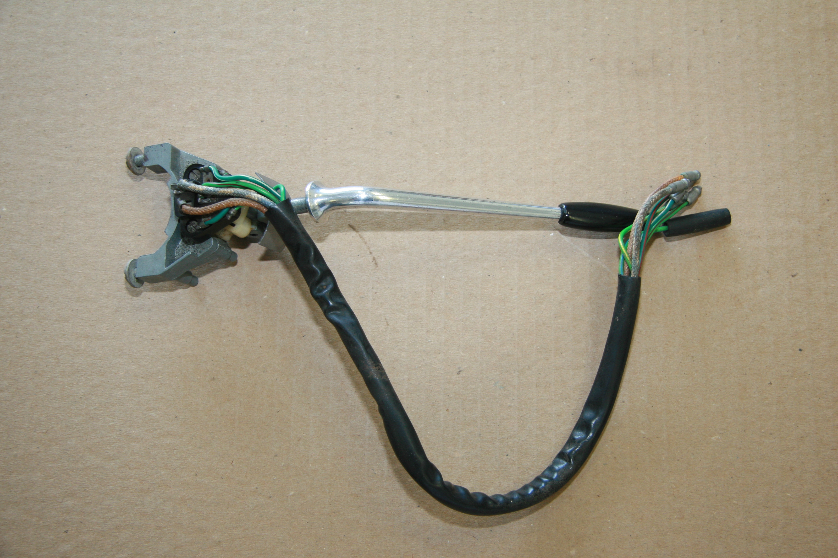
Heater Control Levers
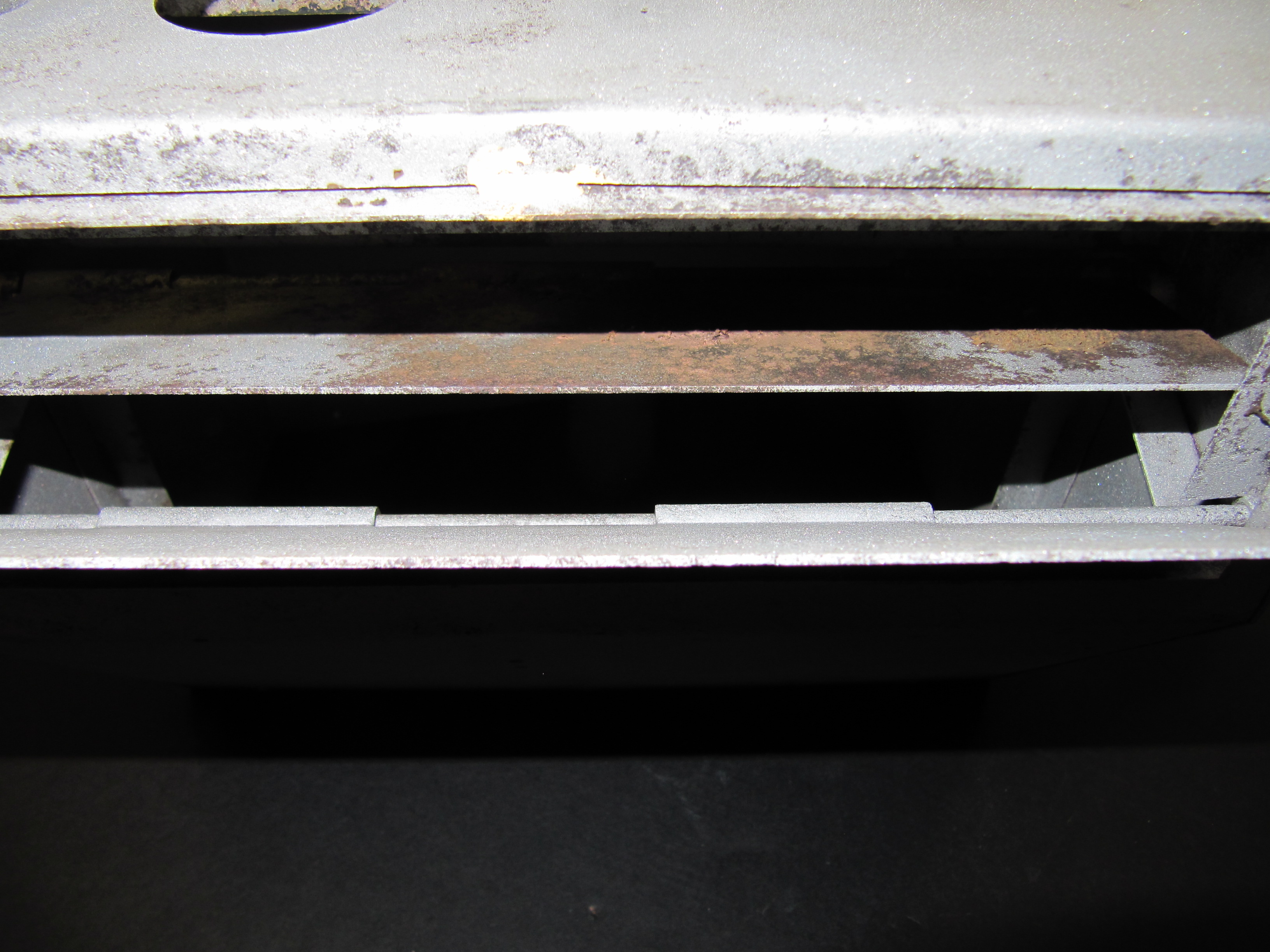
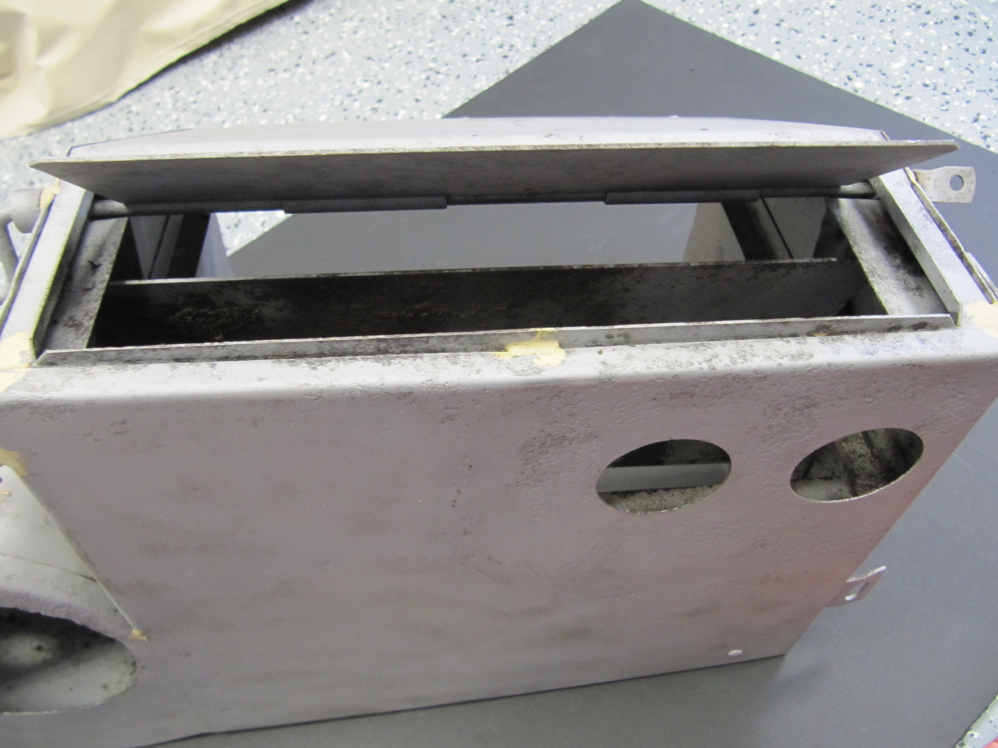
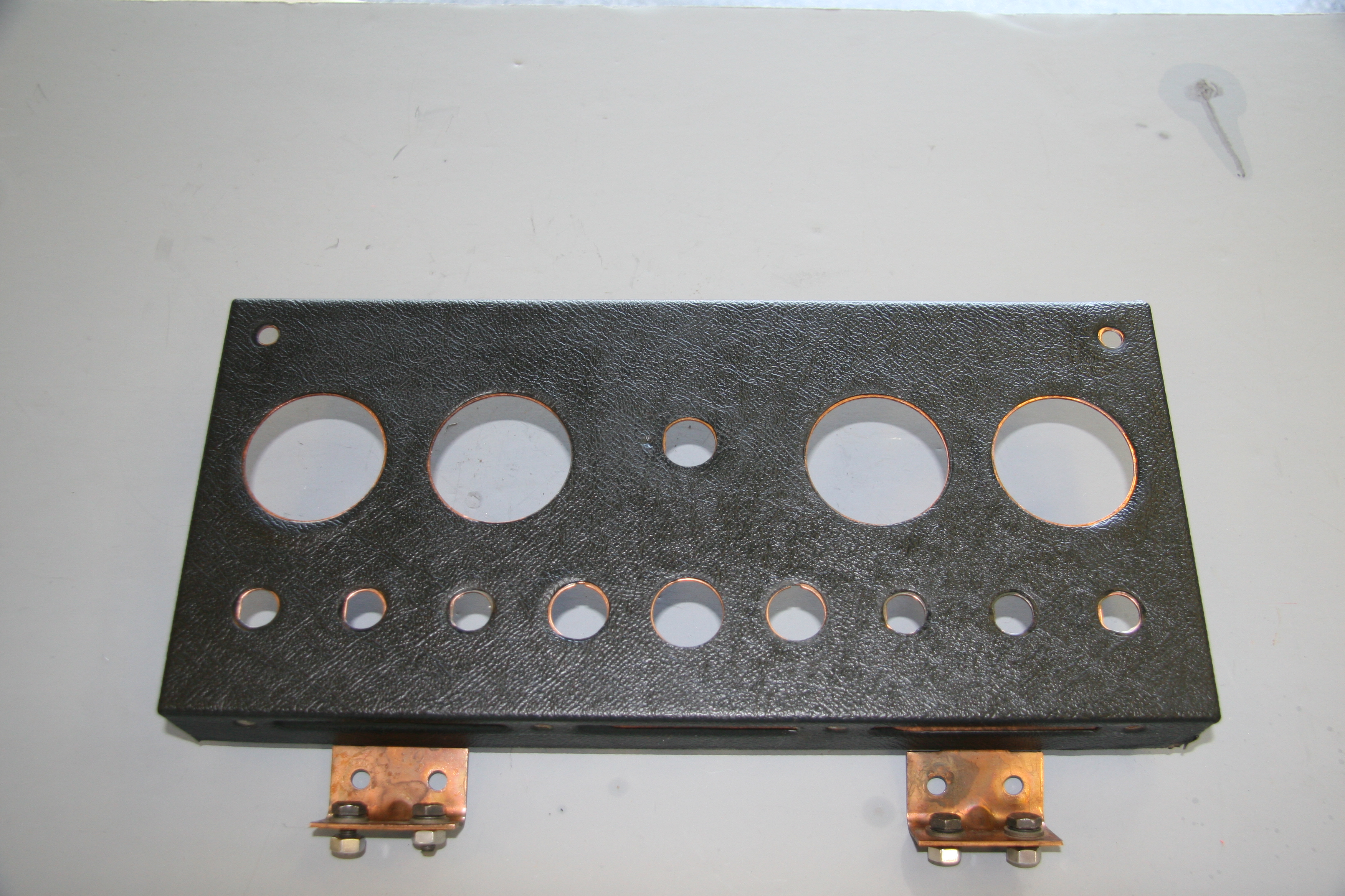
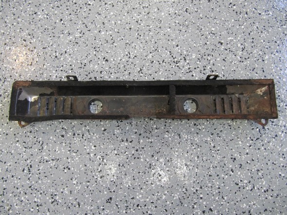
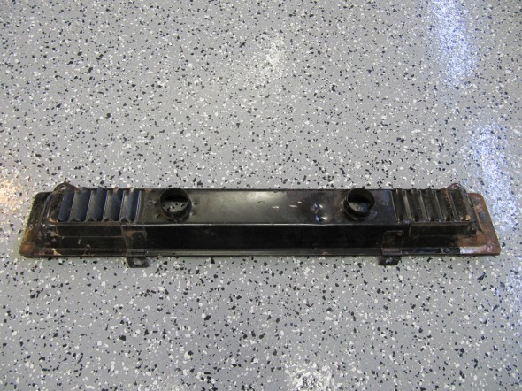
Heater Box
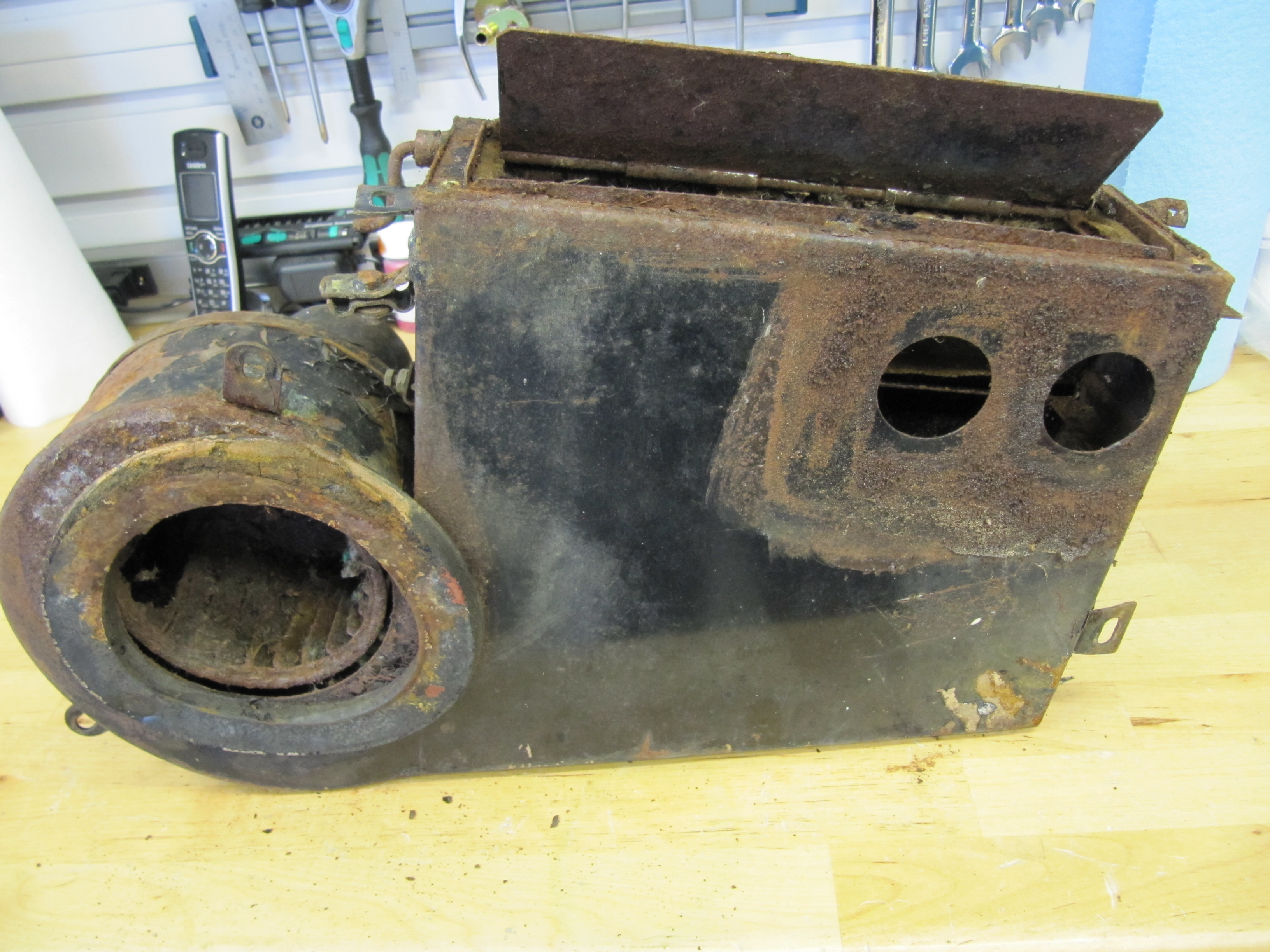
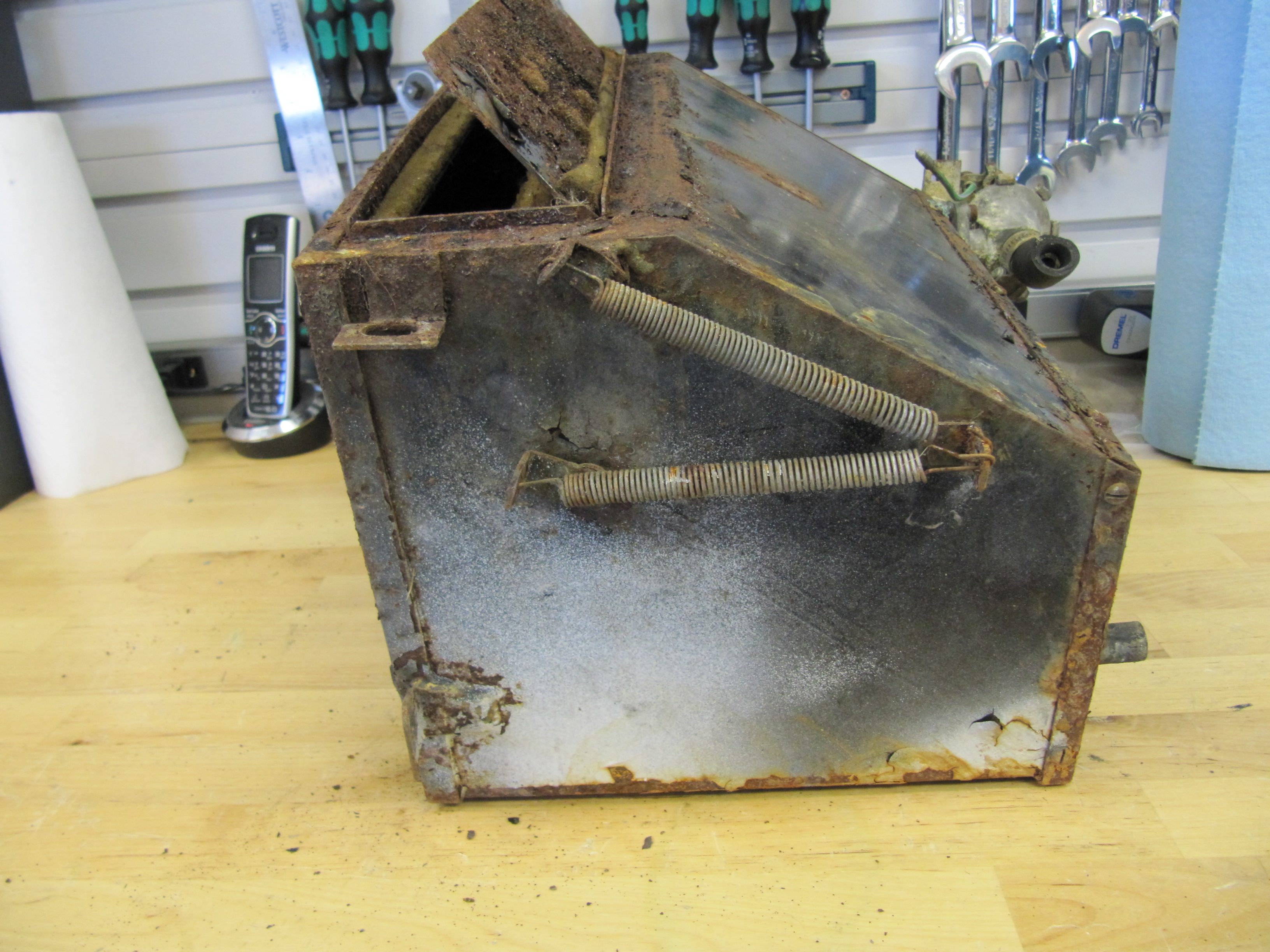
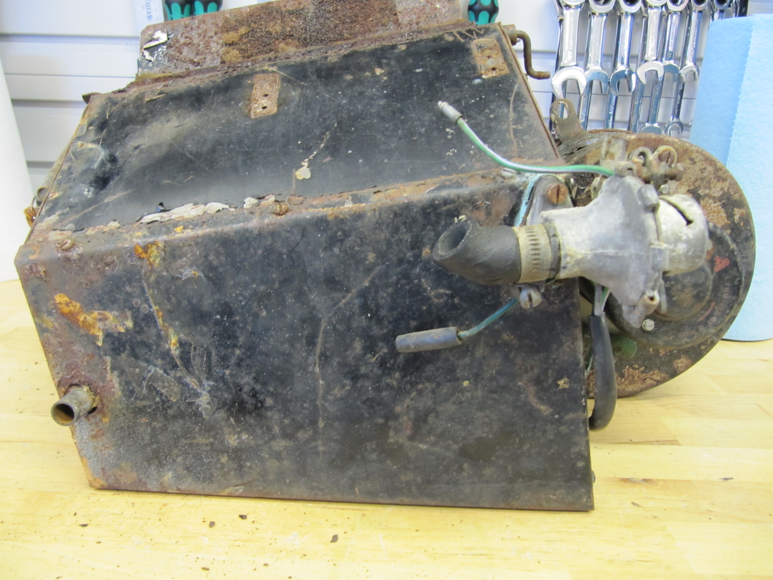
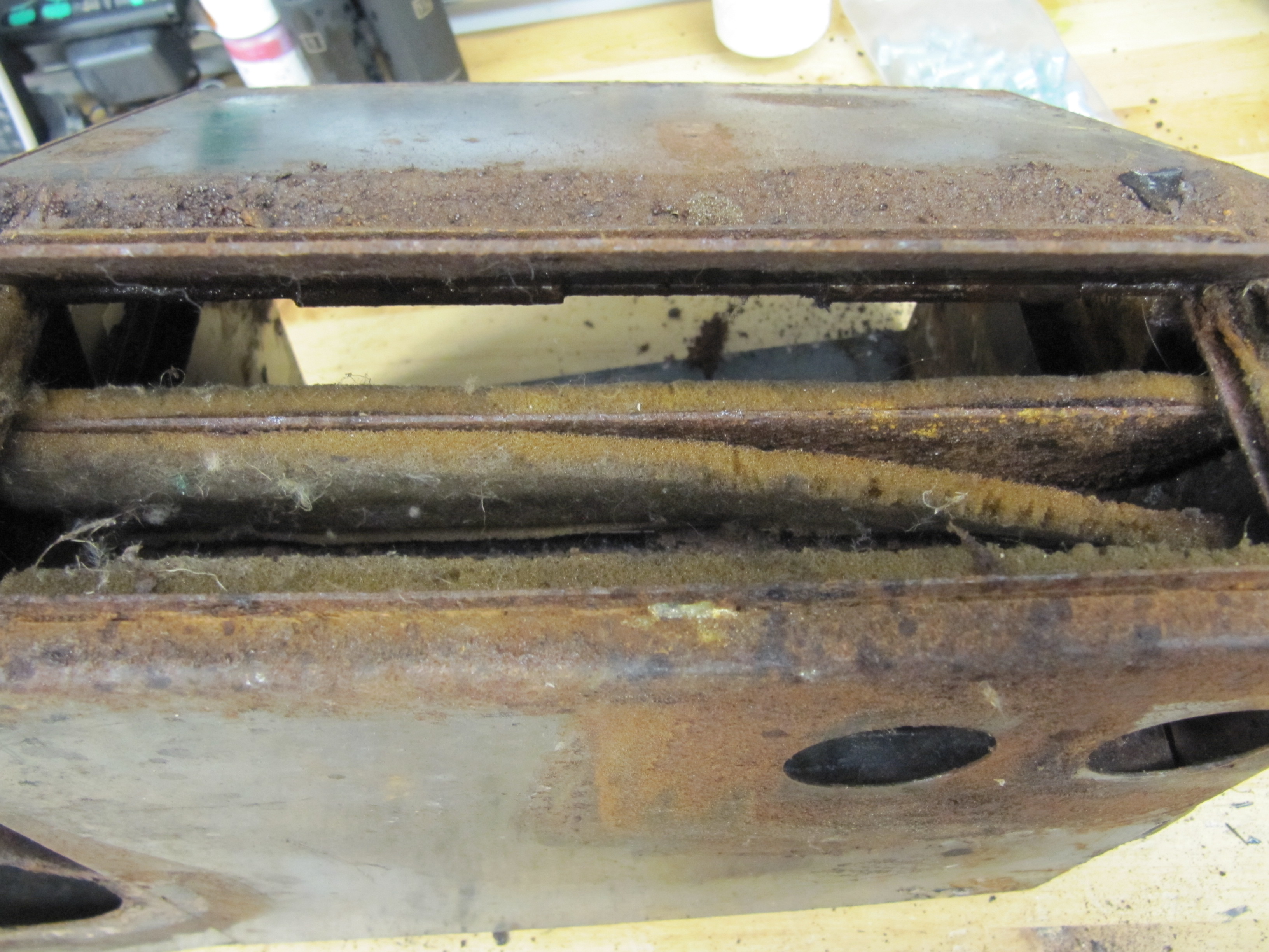
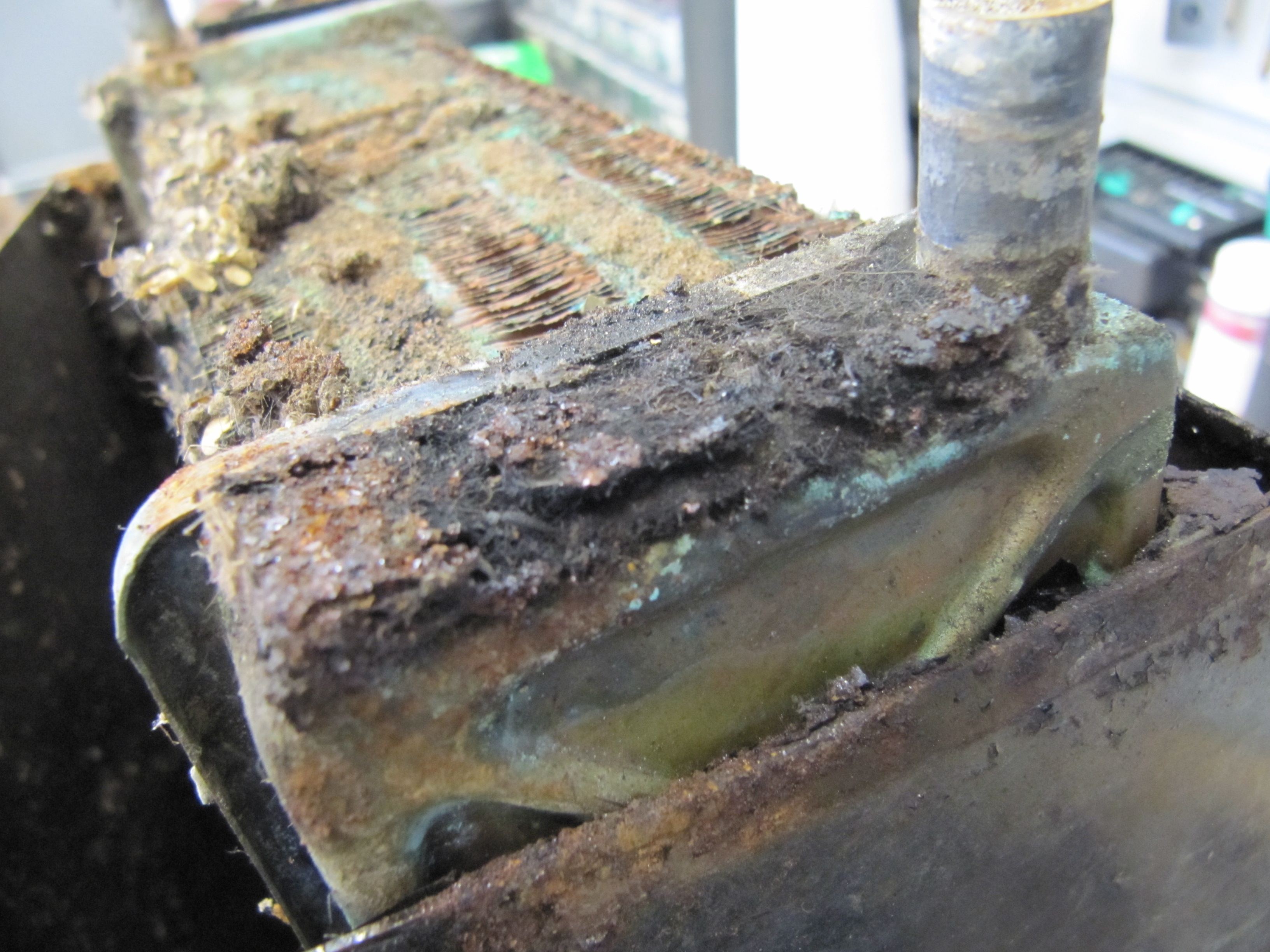
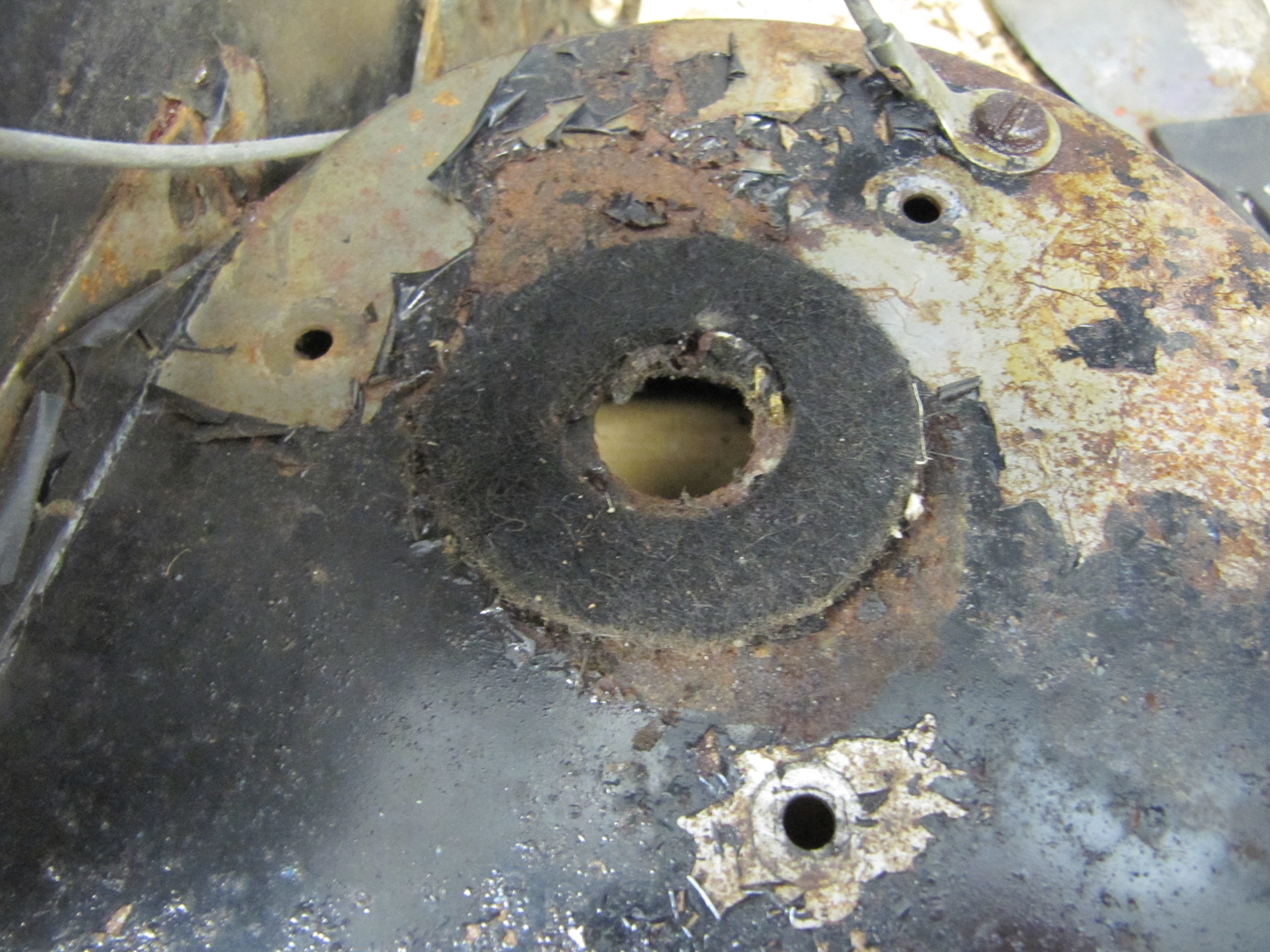
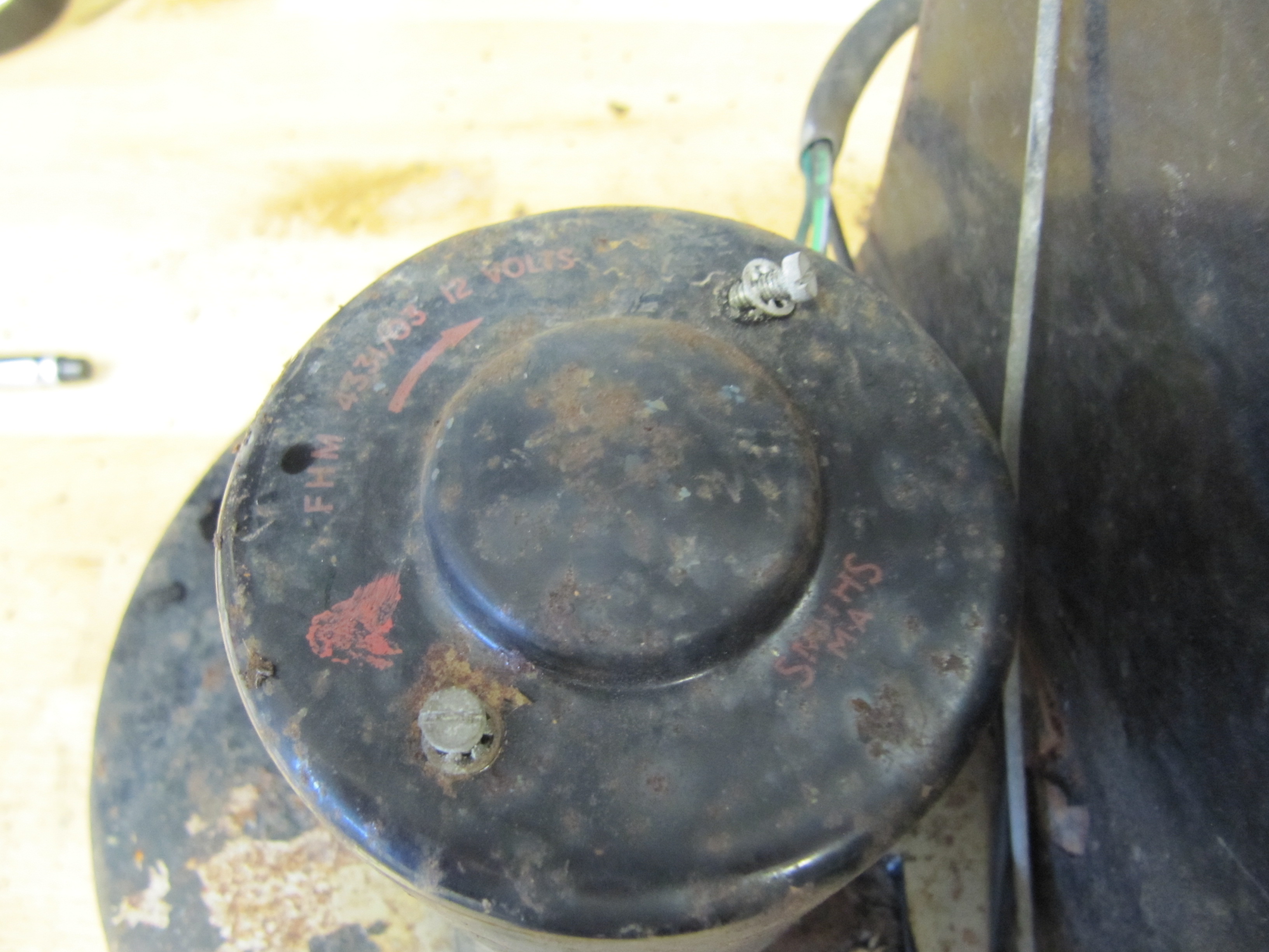
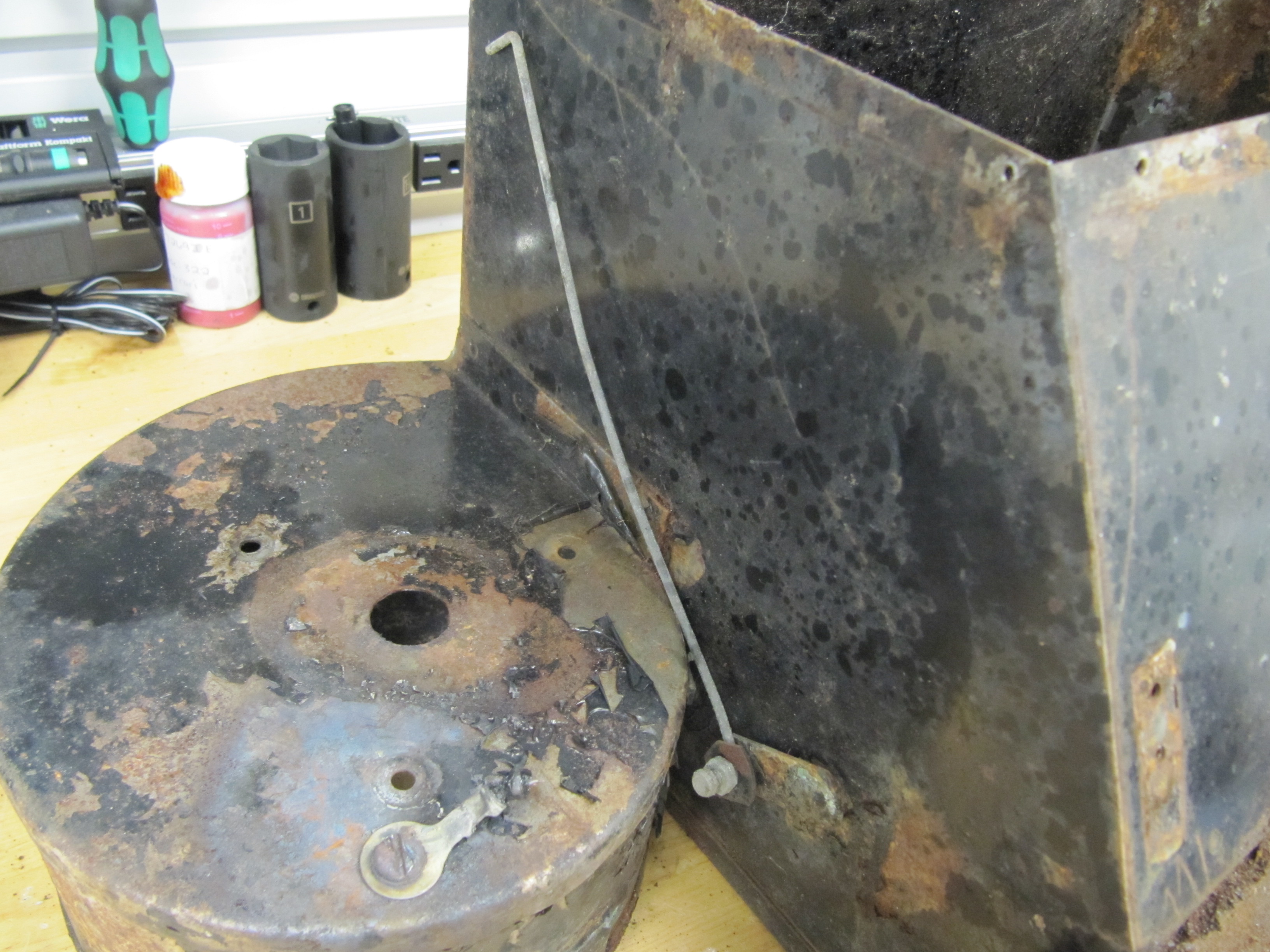
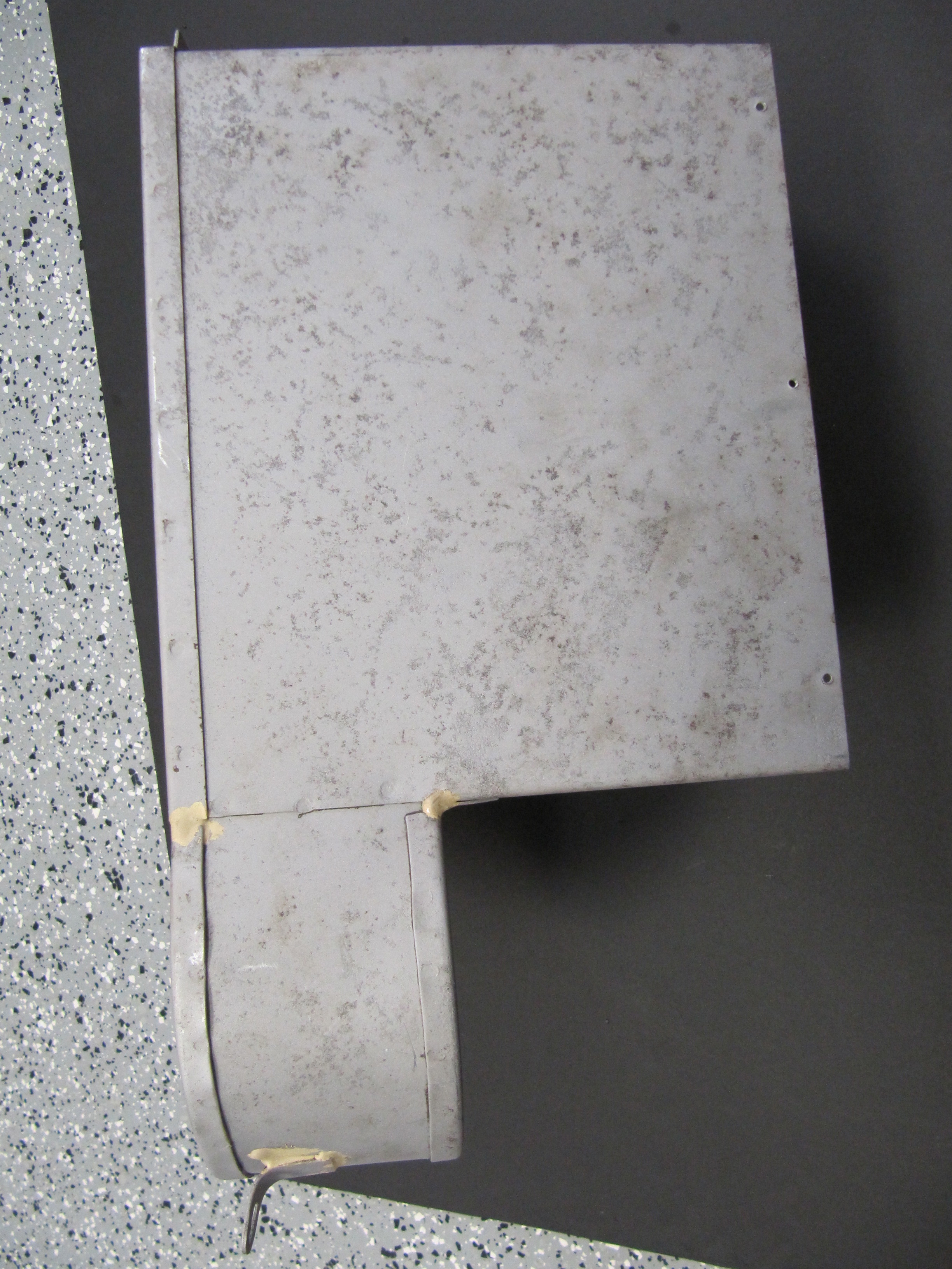
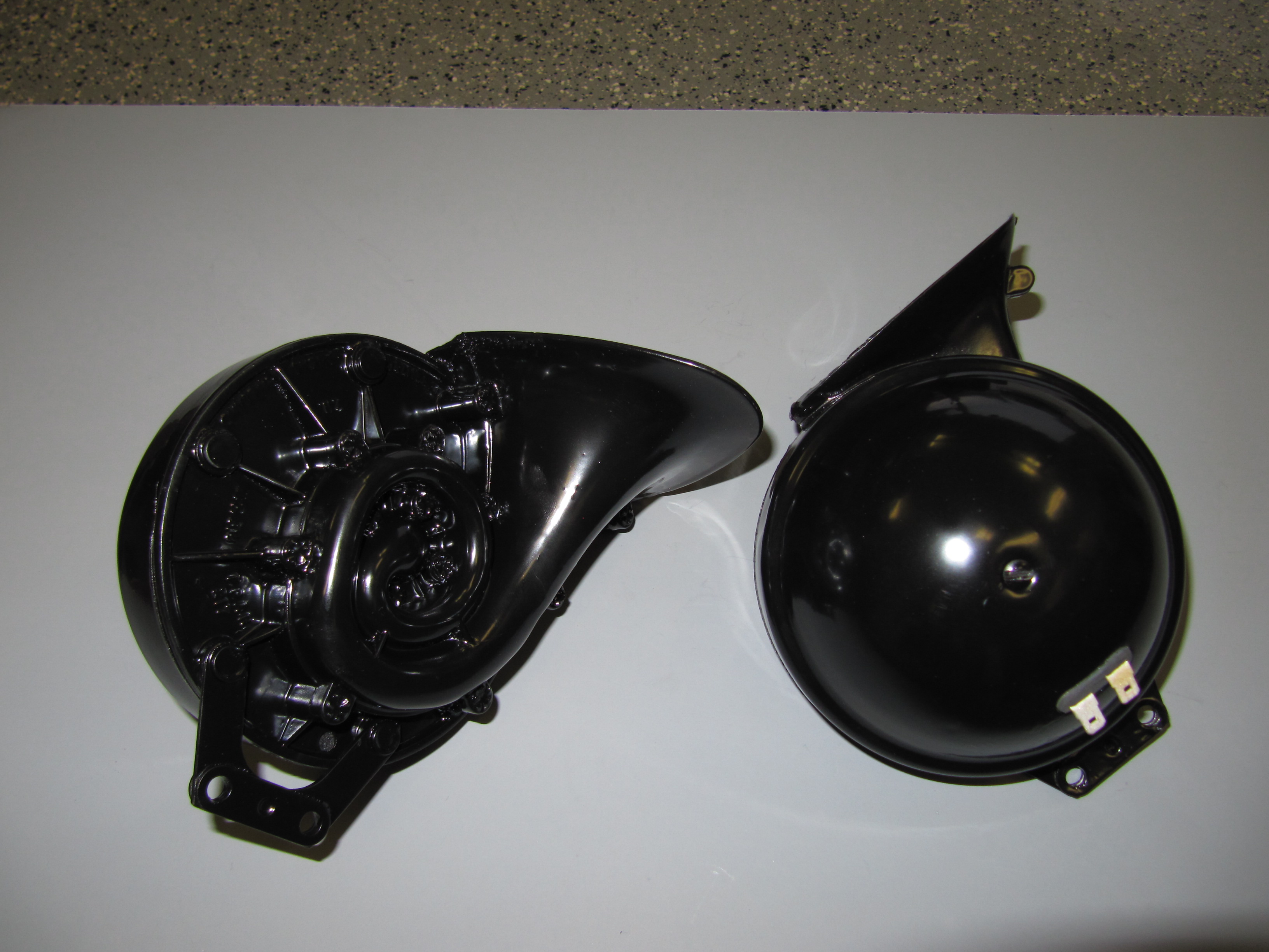
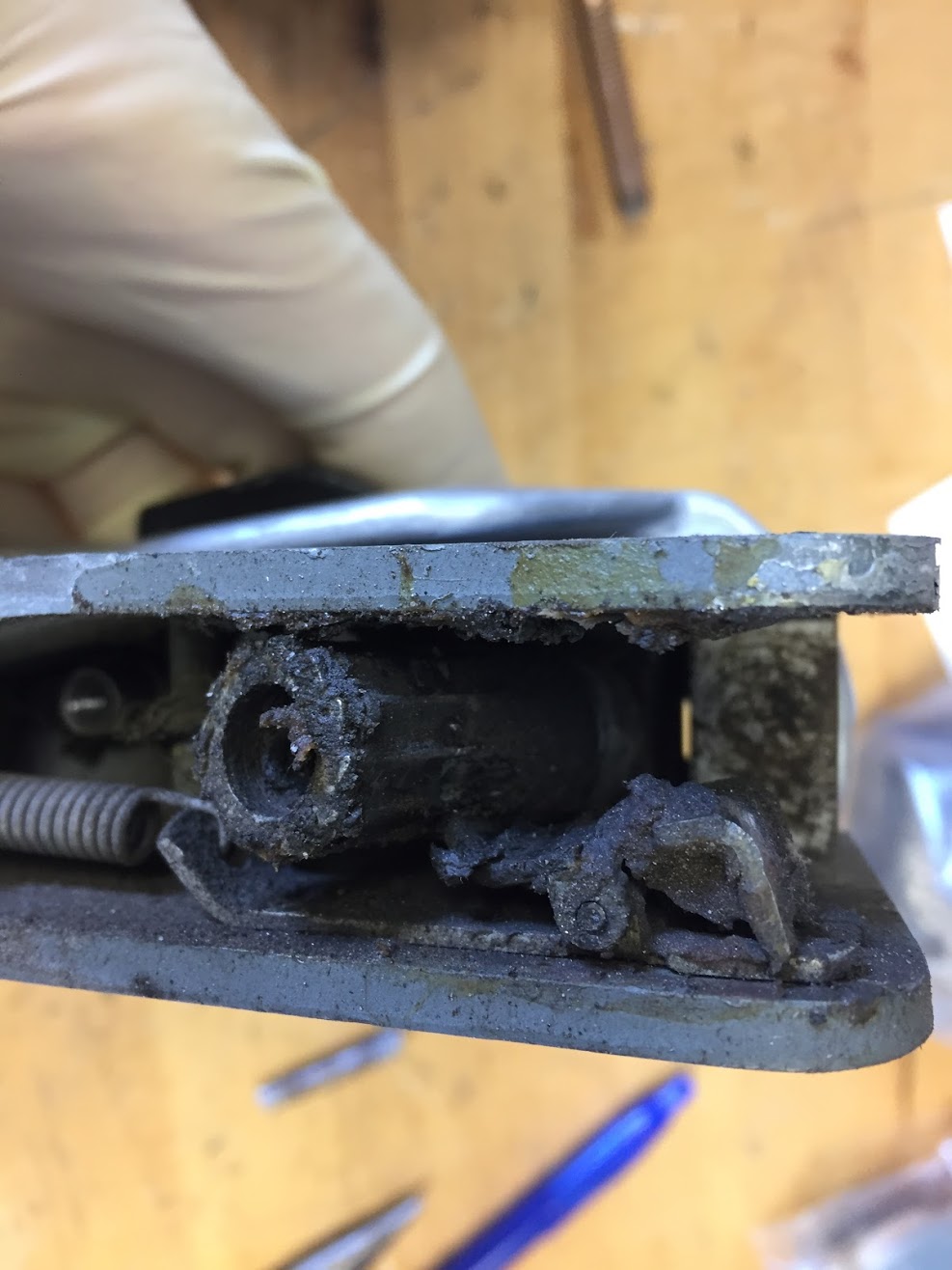
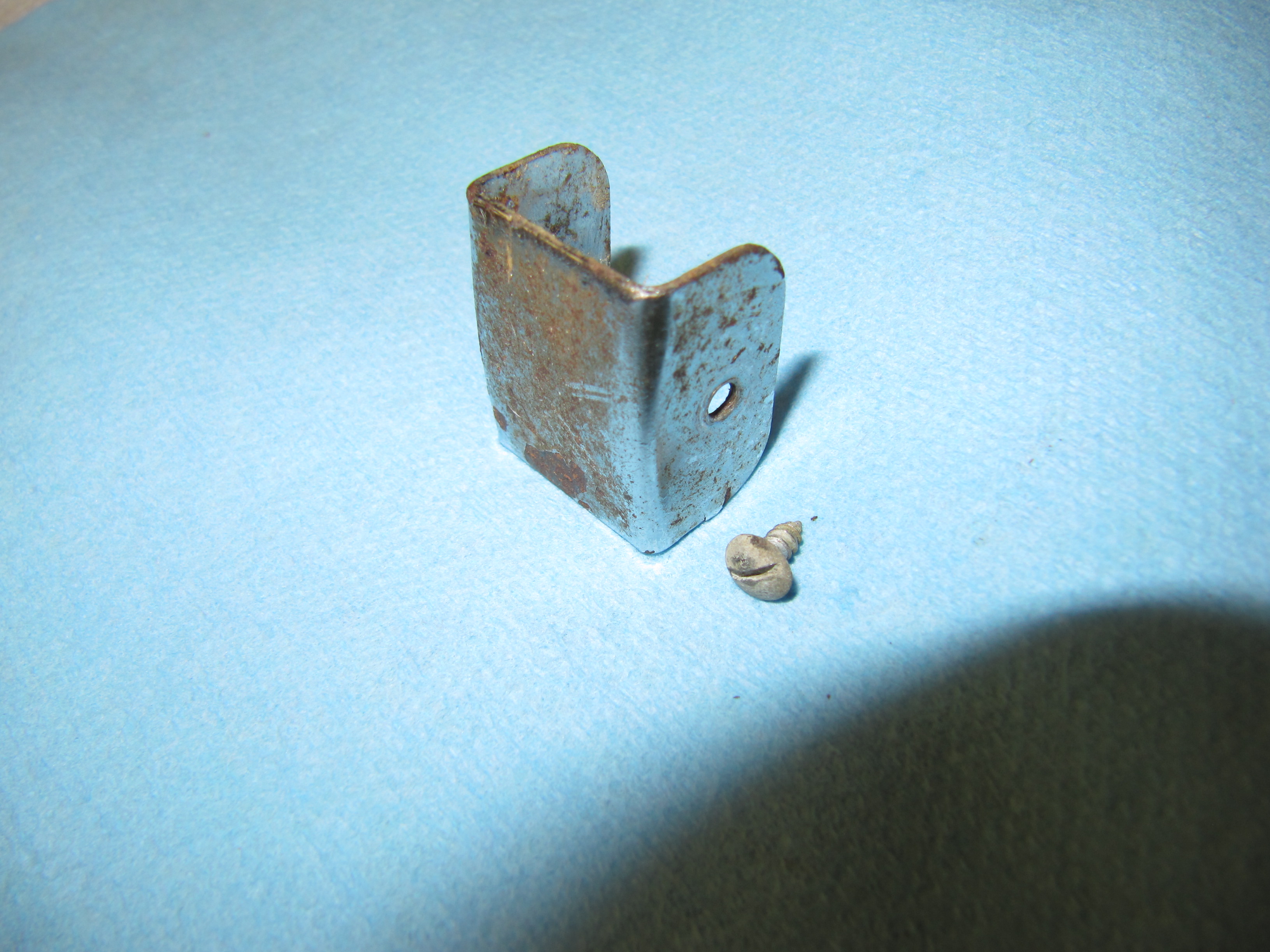
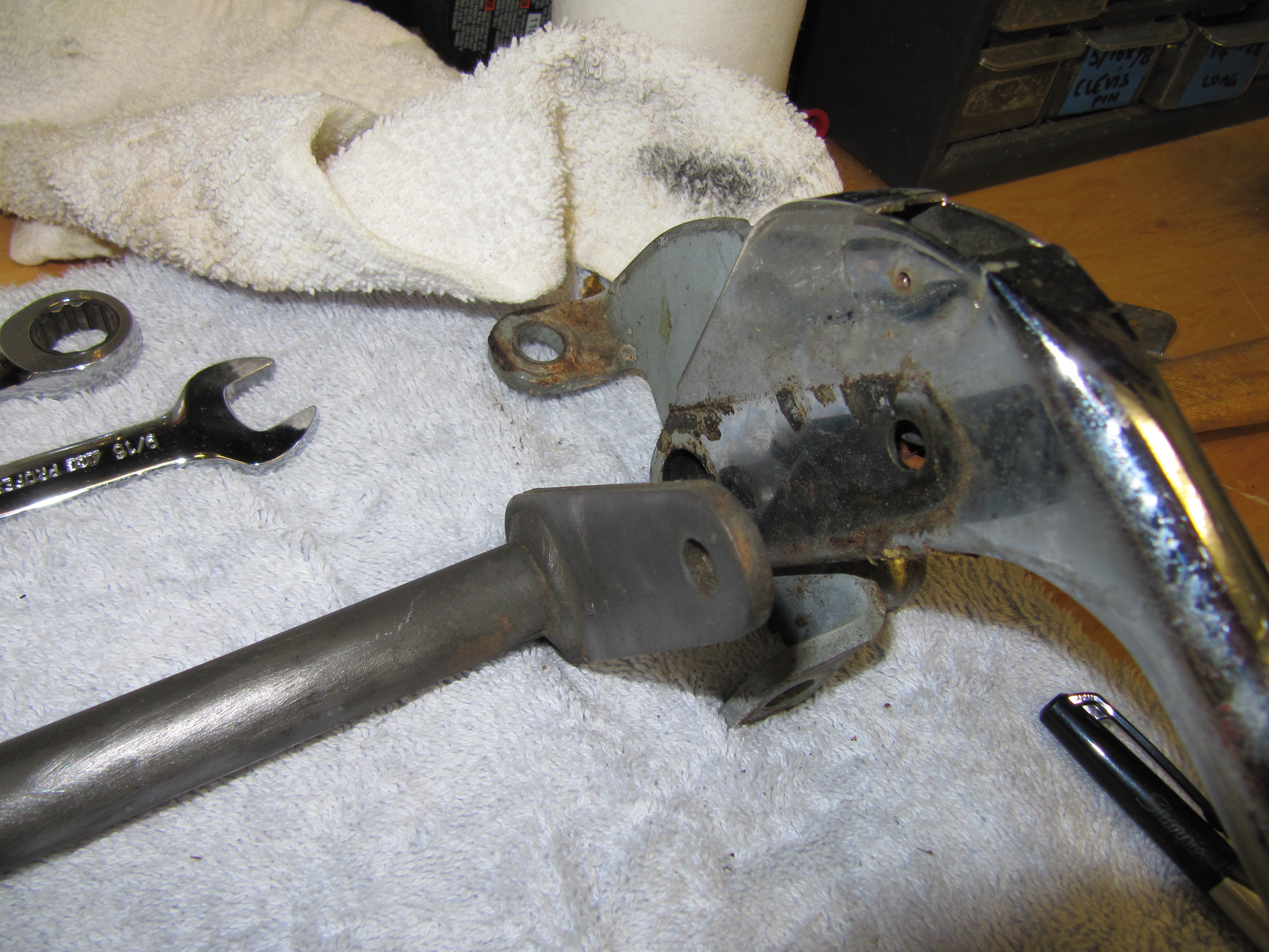
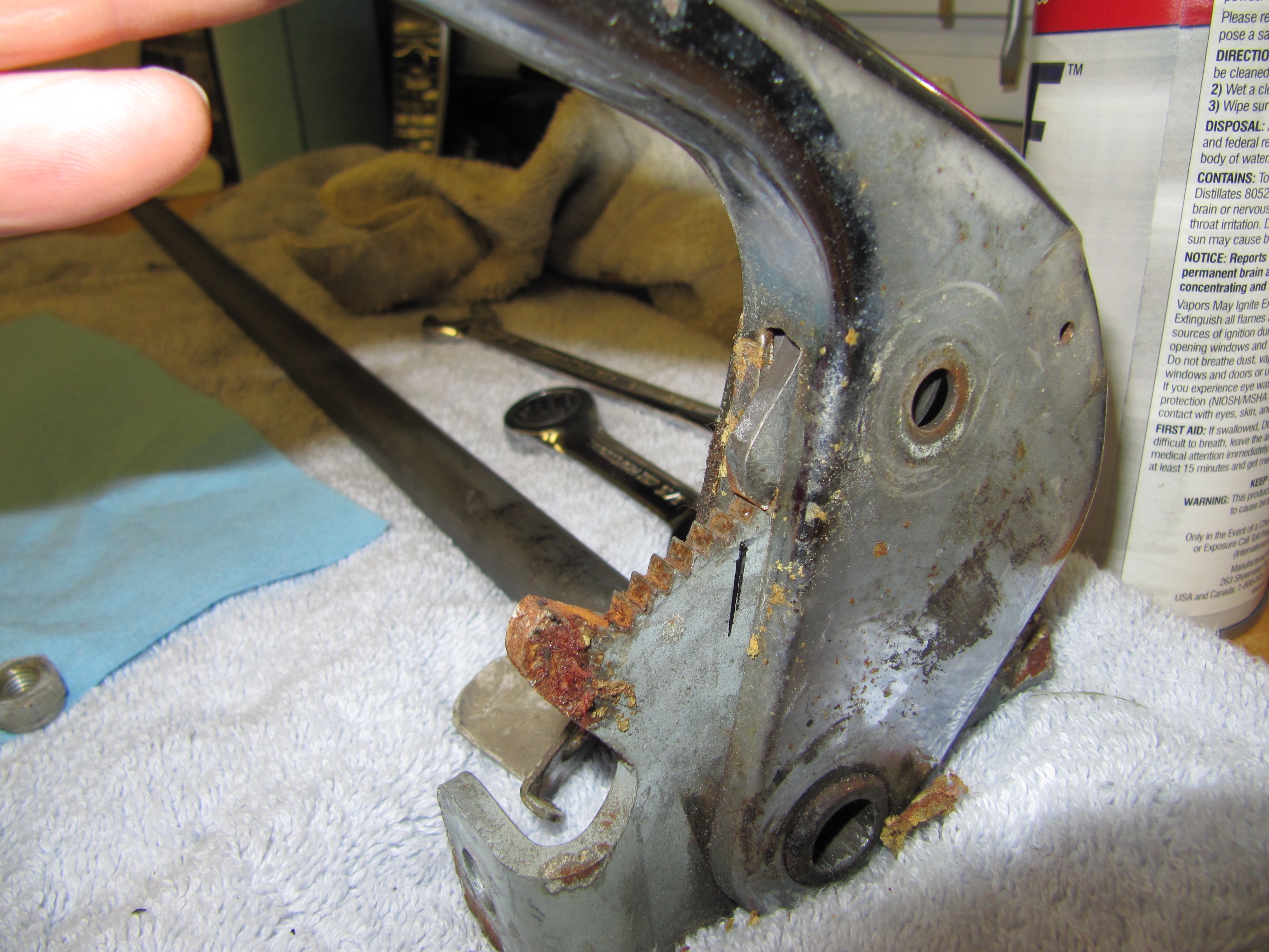
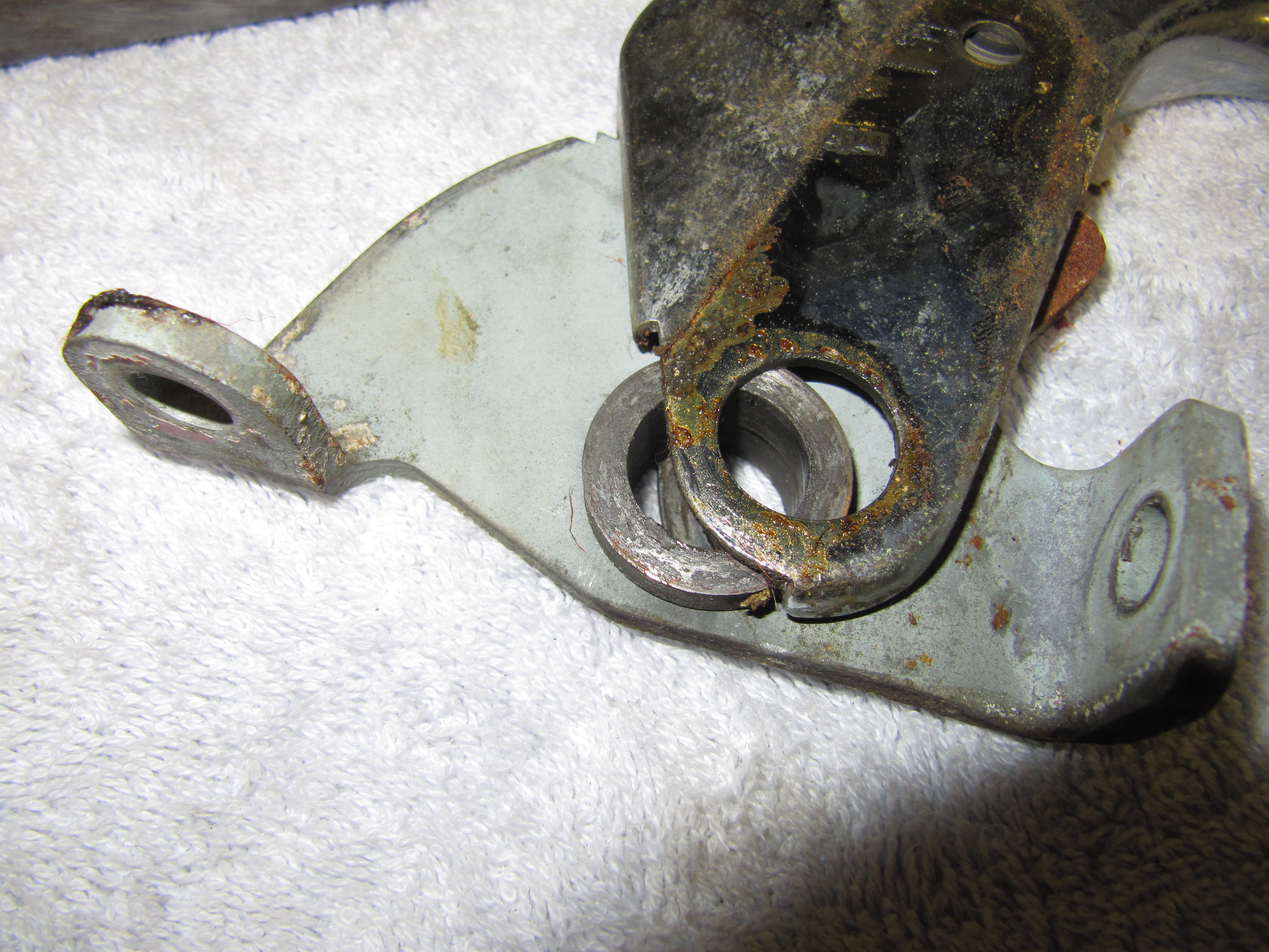
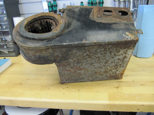
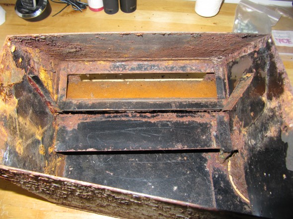
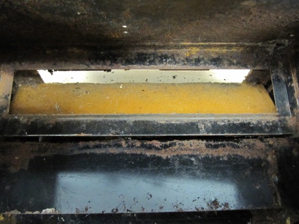
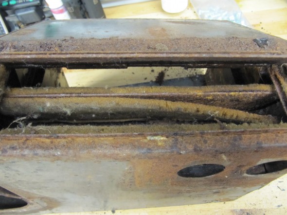
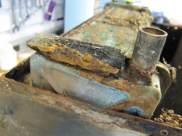
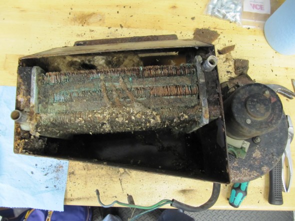
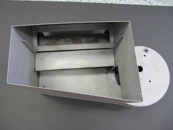
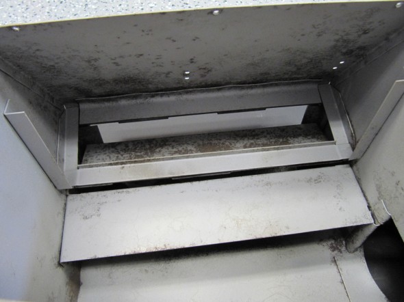
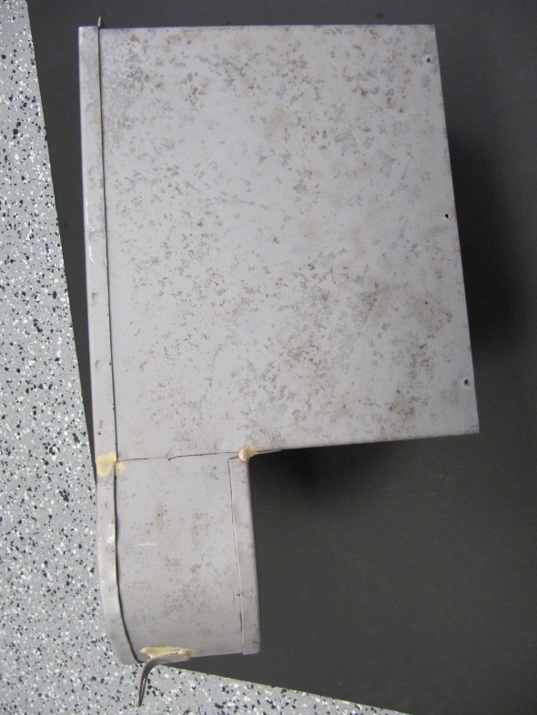
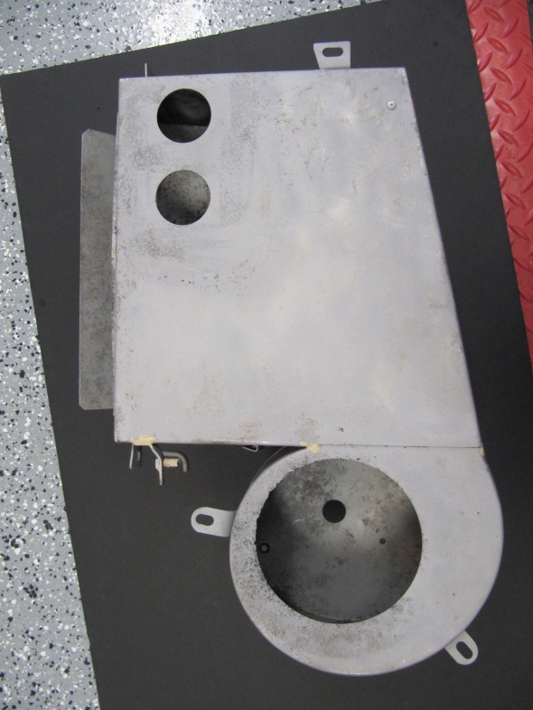
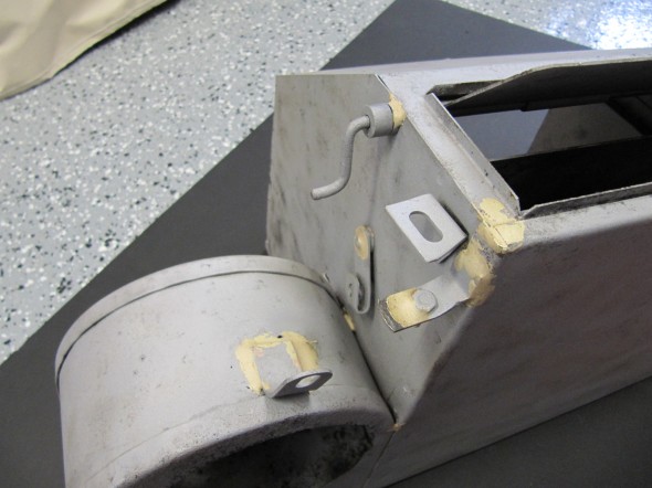
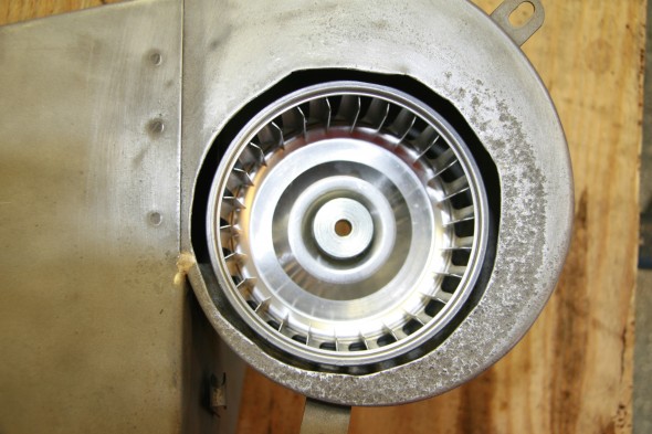
Unfortunately, my heater box assembly seemed to be in a poor state. The drain tube from the plenum must have been clogged which resulted in the system holding moisture combined with the fact that the mice set up home inside the heater casing. The case was pretty rusty, the squirrel cage (fan blower) was completely deteriorated and worst of all the air control flaps were “frozen” in place.
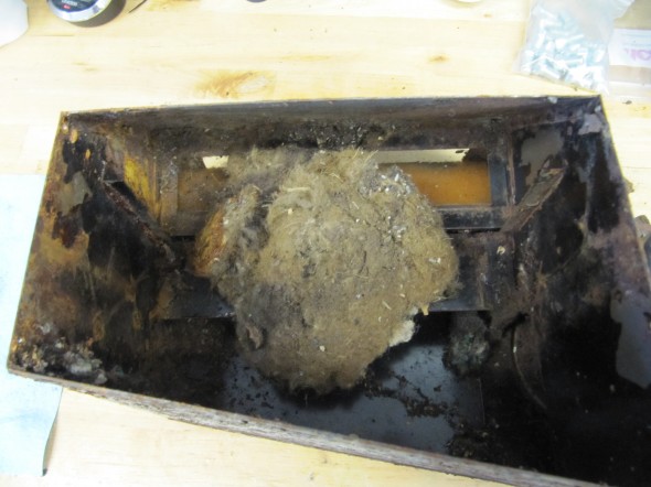
Bonus Mice Nest
I decided to try to restore the box and get the frozen flaps working, so I disassembled the heater and media blast the box to so that I could see just how bad it was.
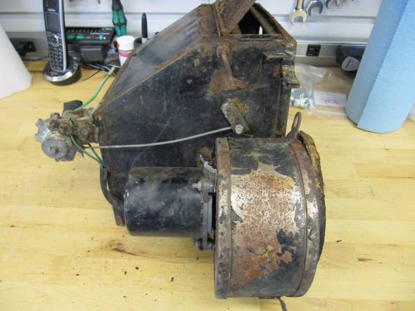
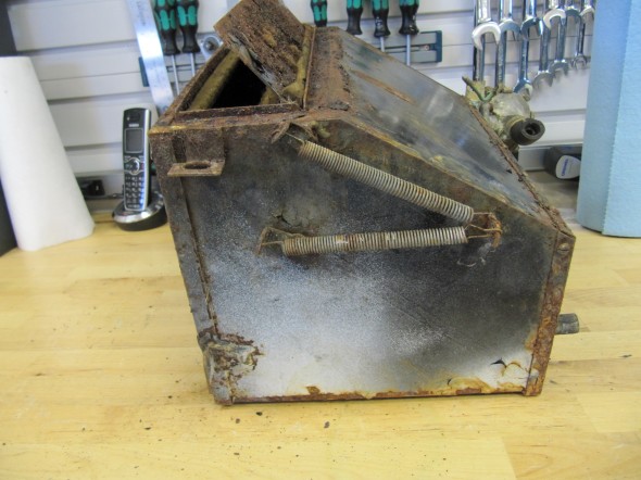
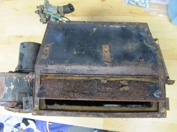
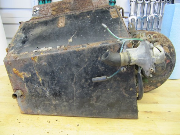
These are some images of the heater before I began disassembly:
Heater Box 1

Heater Box
Heater Box 1
Heater Box
Heater Box
Heater Box
Heater Box
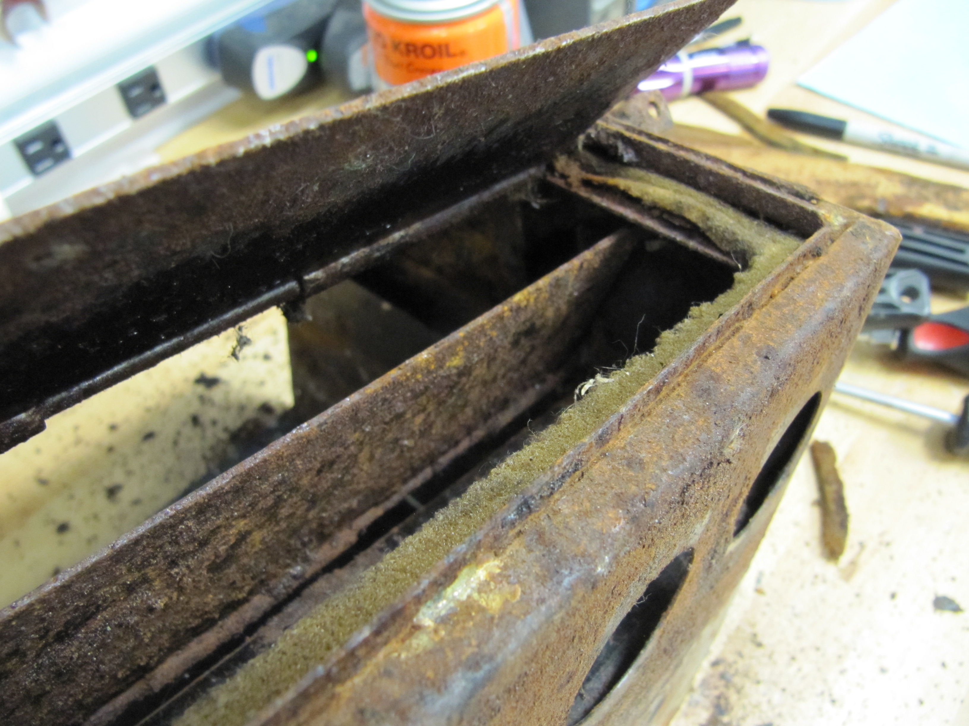
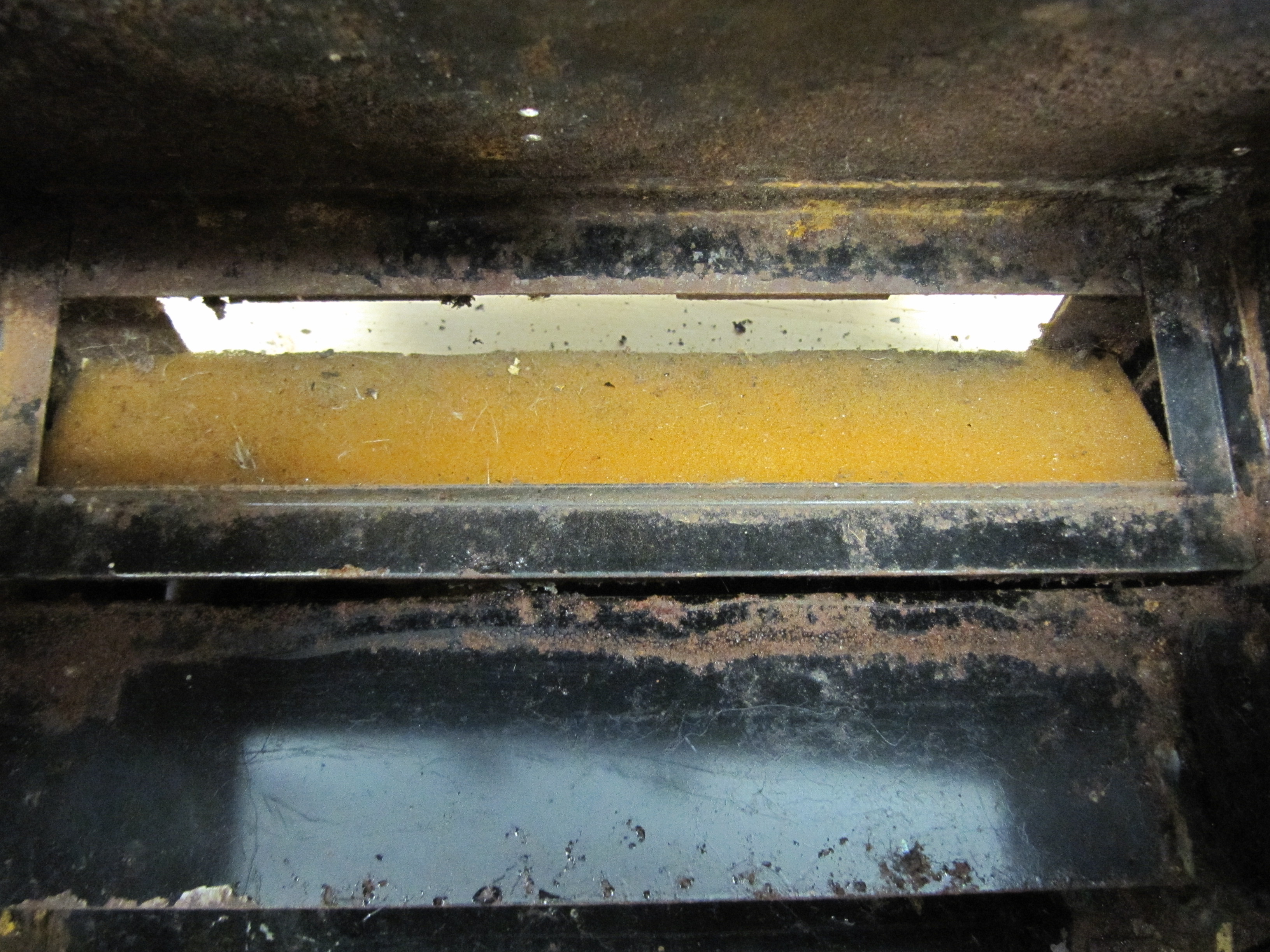
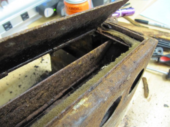
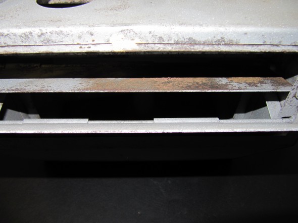
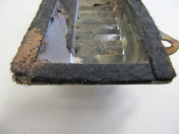
These images show the foam rubber seals around the flaps:
Flap Seal
Flap Seal
Flap Seal
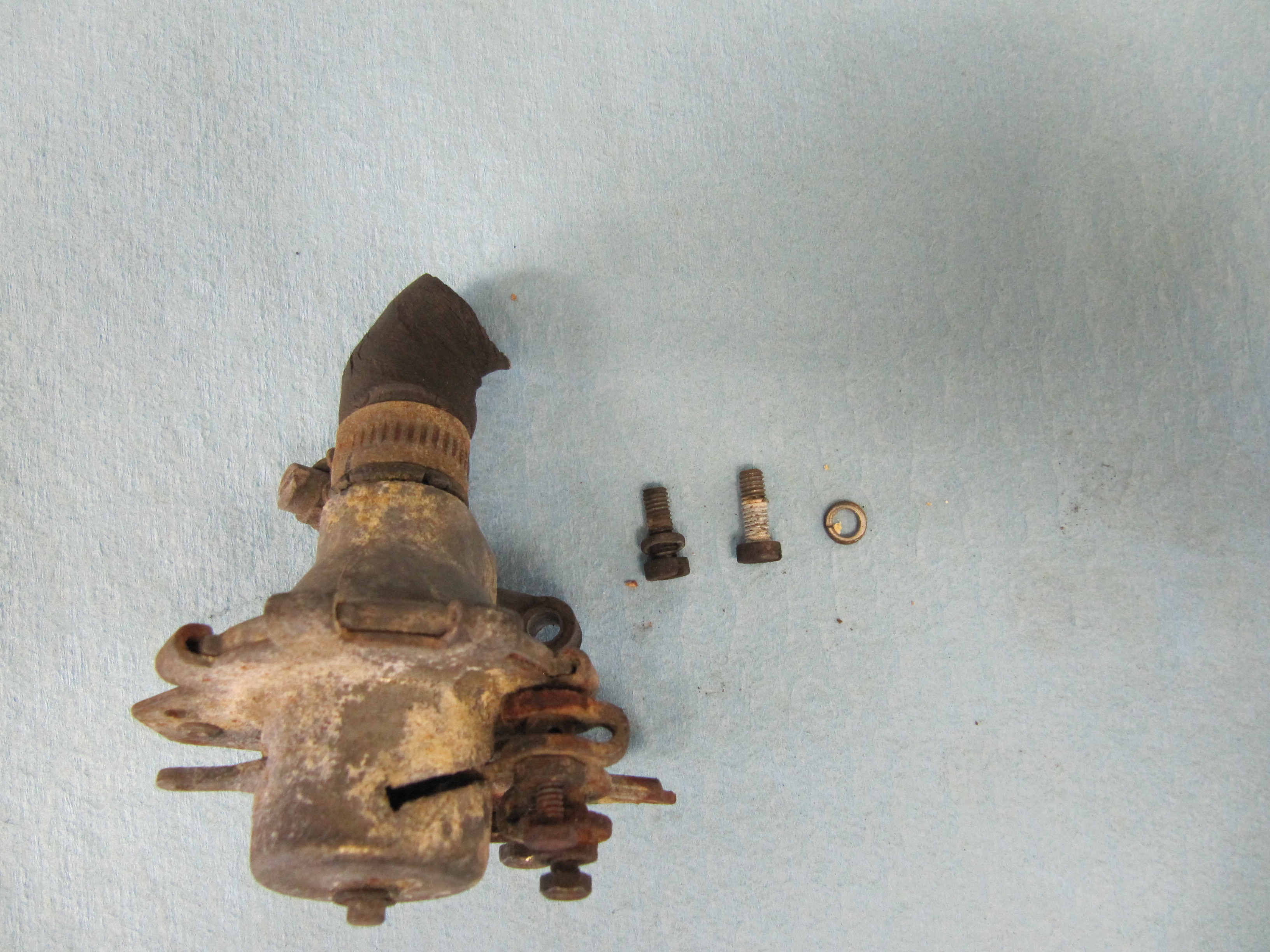
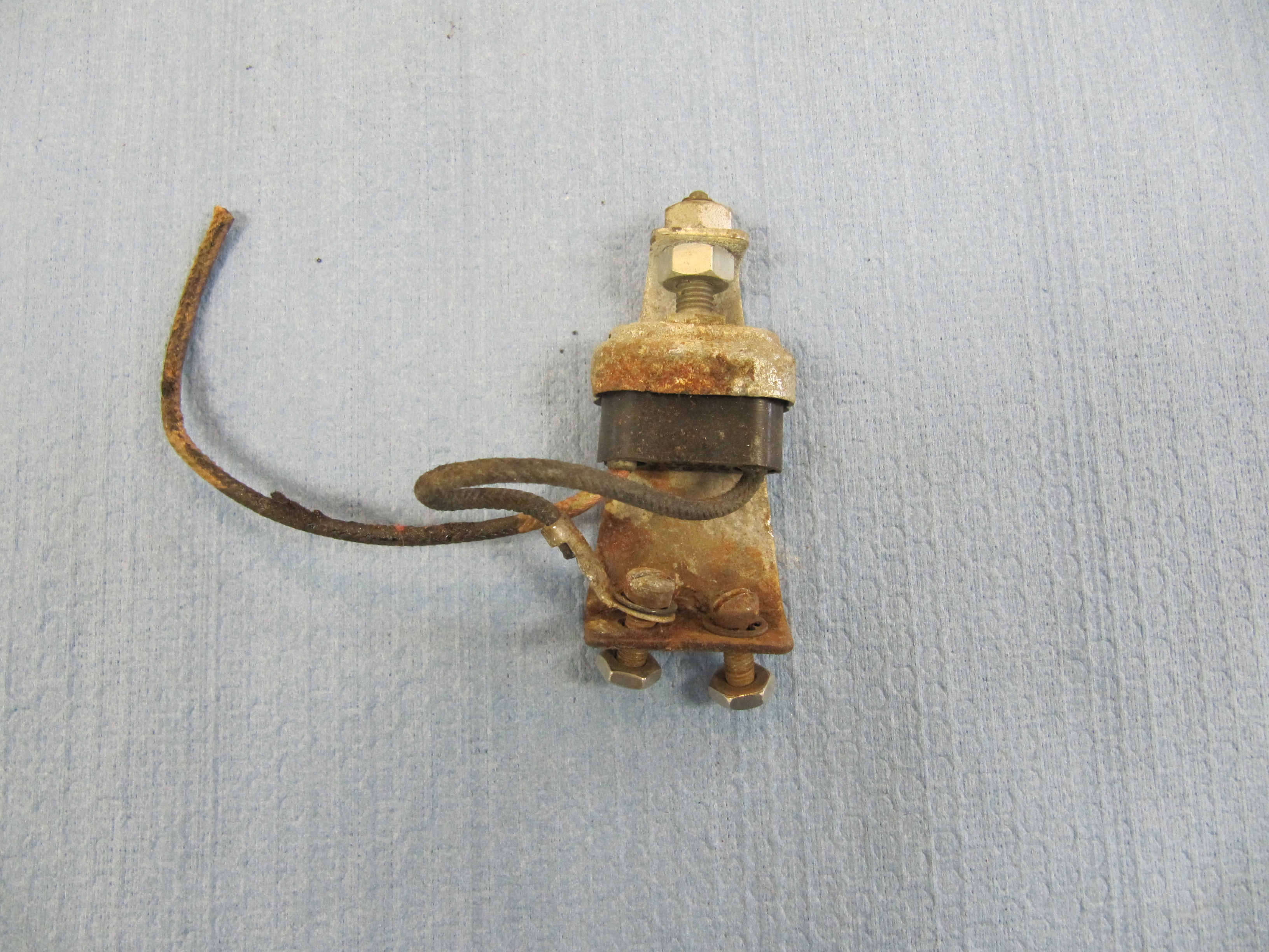
There was a rather thick foam rubber seal between the Heater and the Dash at Volute. This was removed and will be replaced with a new seal. I then removed the Water valve Assembly form the box by removing two cheese head slotted screws #10-32 x 1/2″ with split washers, and the rubber seal that seated the valve to the radiator pipe.

Foam Seal to Body
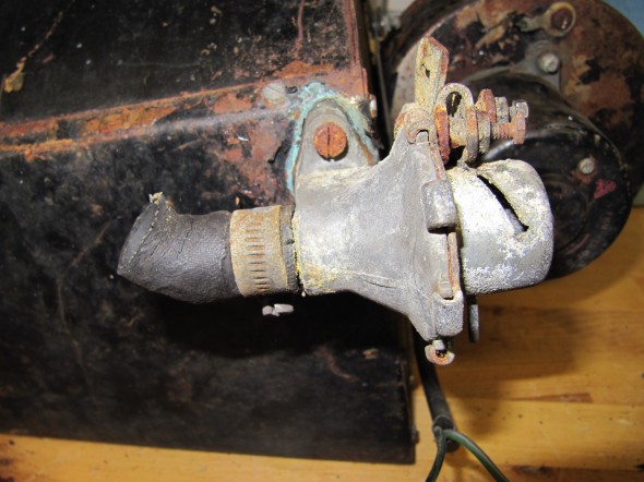
Water Valve Assembly

Water Valve Assembly

Water Valve Assembly

Water Valve Mount
Heater Seals to Firewall
There were 11 slotted #5 x 1/4″ self-tapping screws that held the Lid for the Heater Case to the body of the casing. I removed these to then gain access to the radiator.
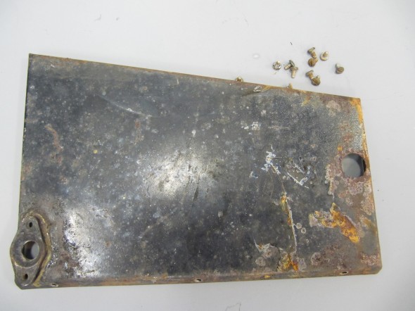
Lid for Heater Case
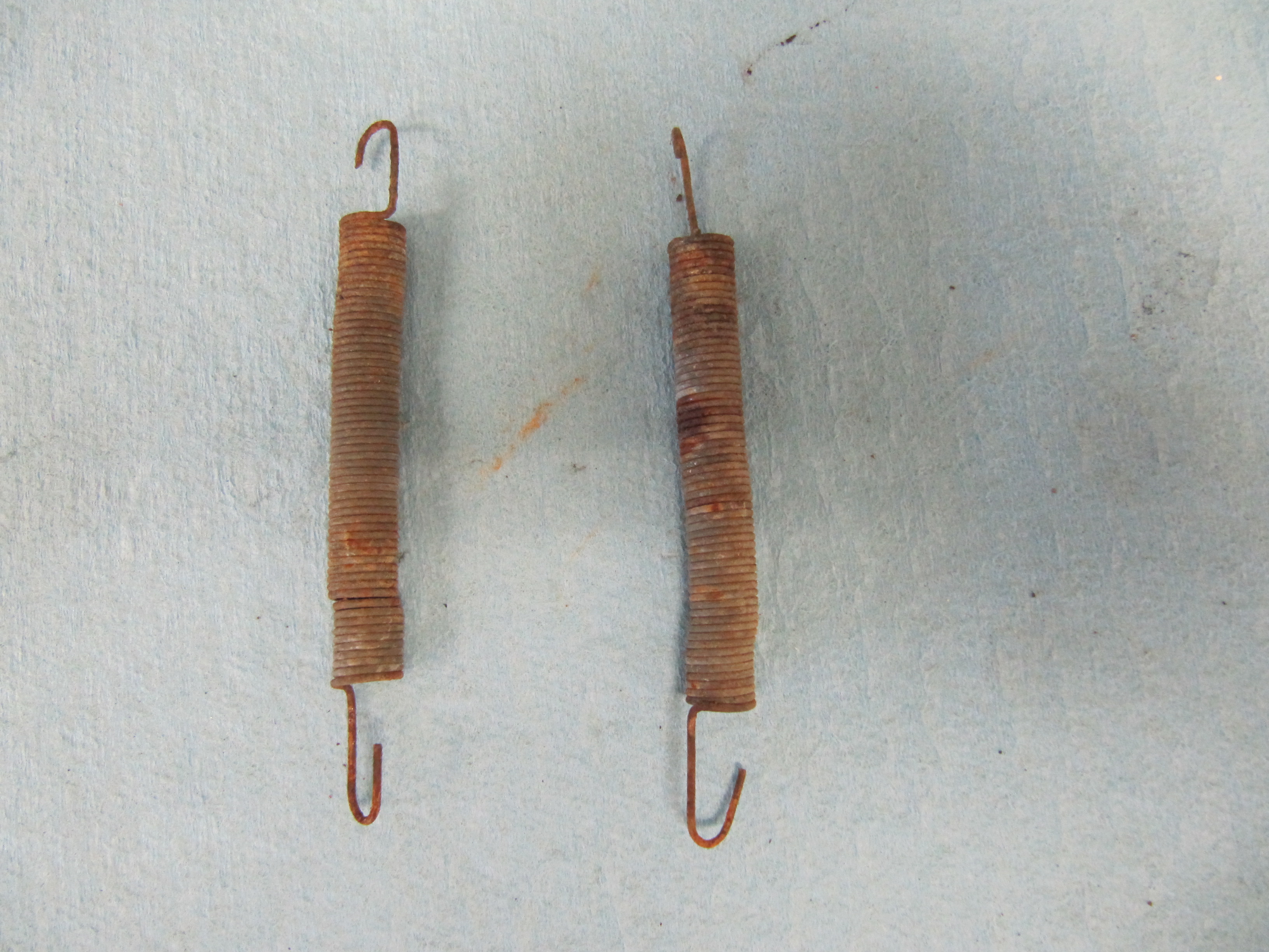
There were two Springs on the outside of the Case identified as Spring, Steadying Air Control Flaps. These were removed and set aside. There were also pieces of felt that provided a cushion between the casing and the radiator. These were removed.

Springs
Felt Seal

Felt Seal
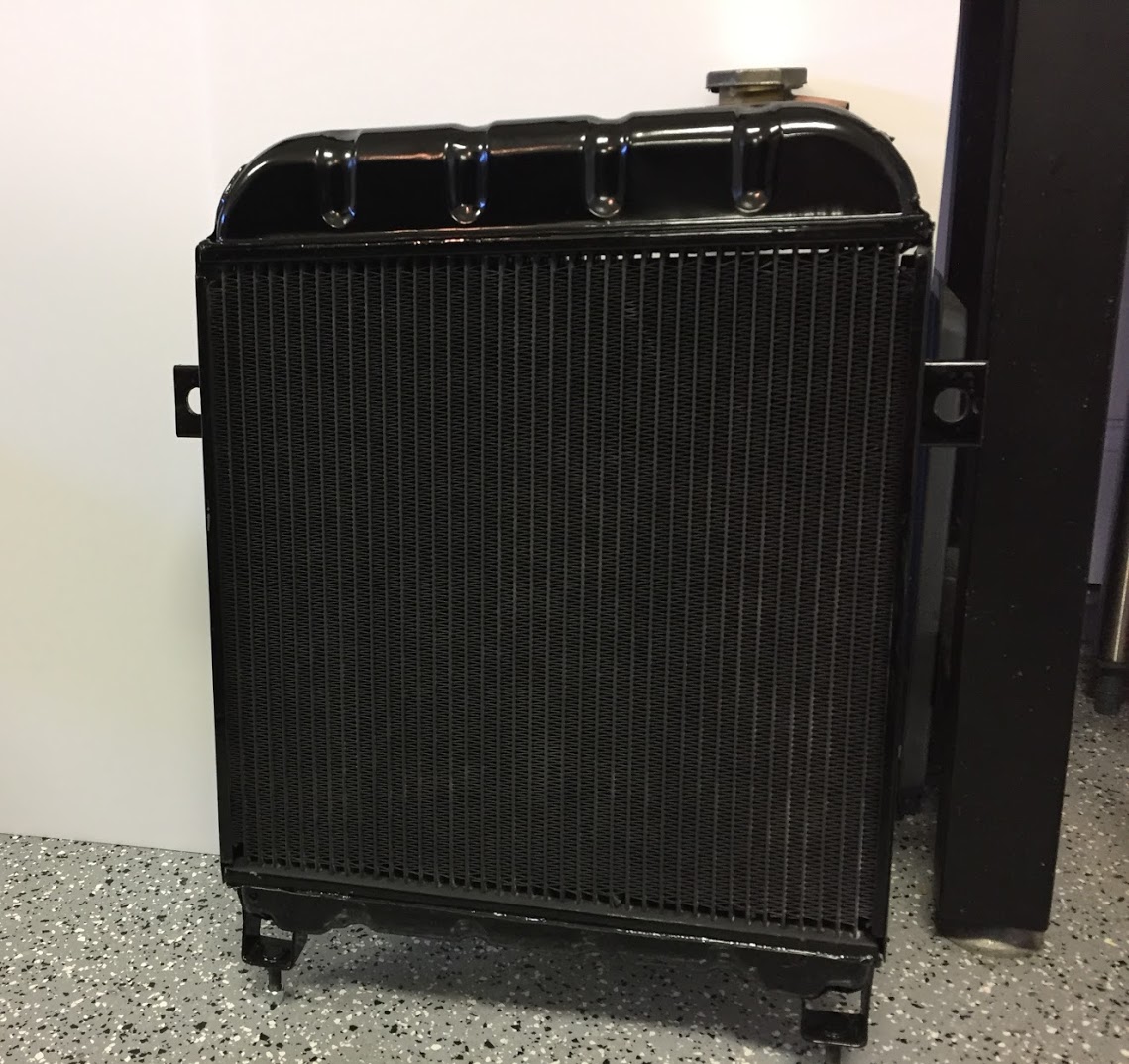
I then lifted out the radiator:
Water Radiator For Heater
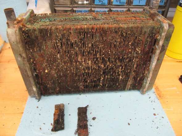
Water Radiator For Heater
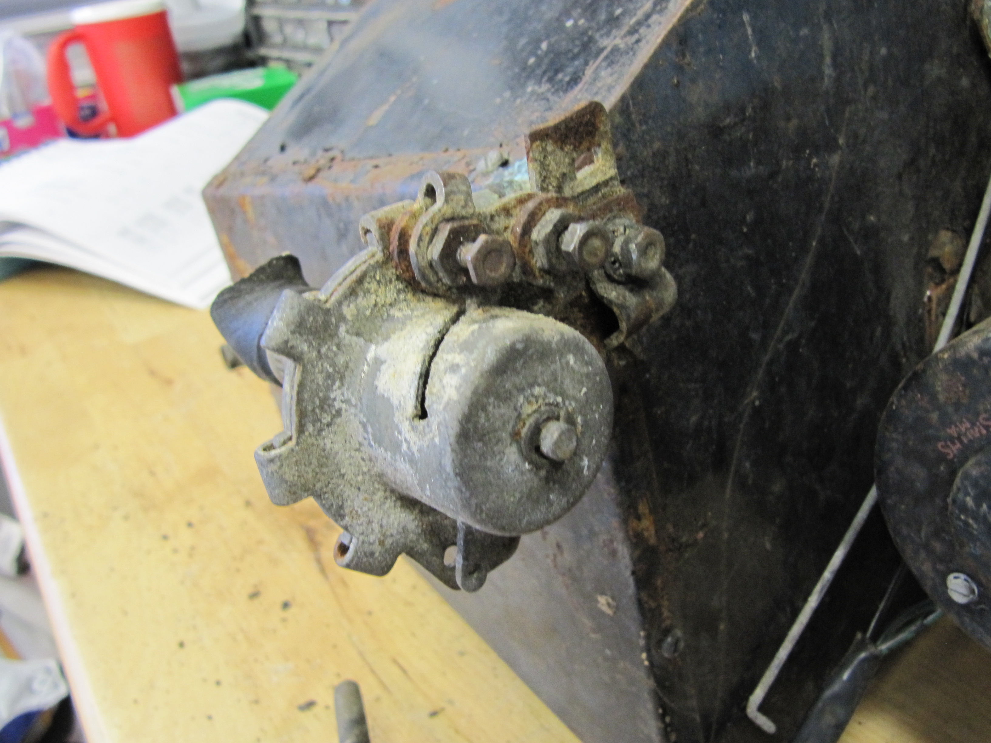
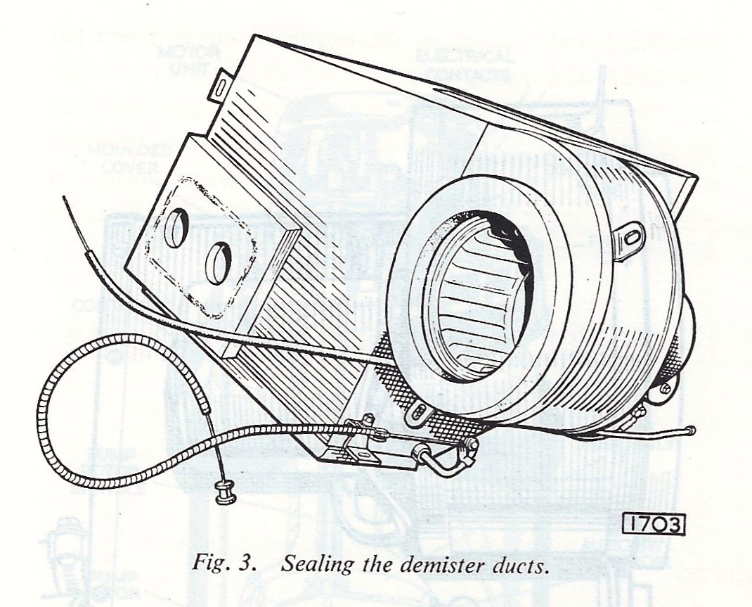
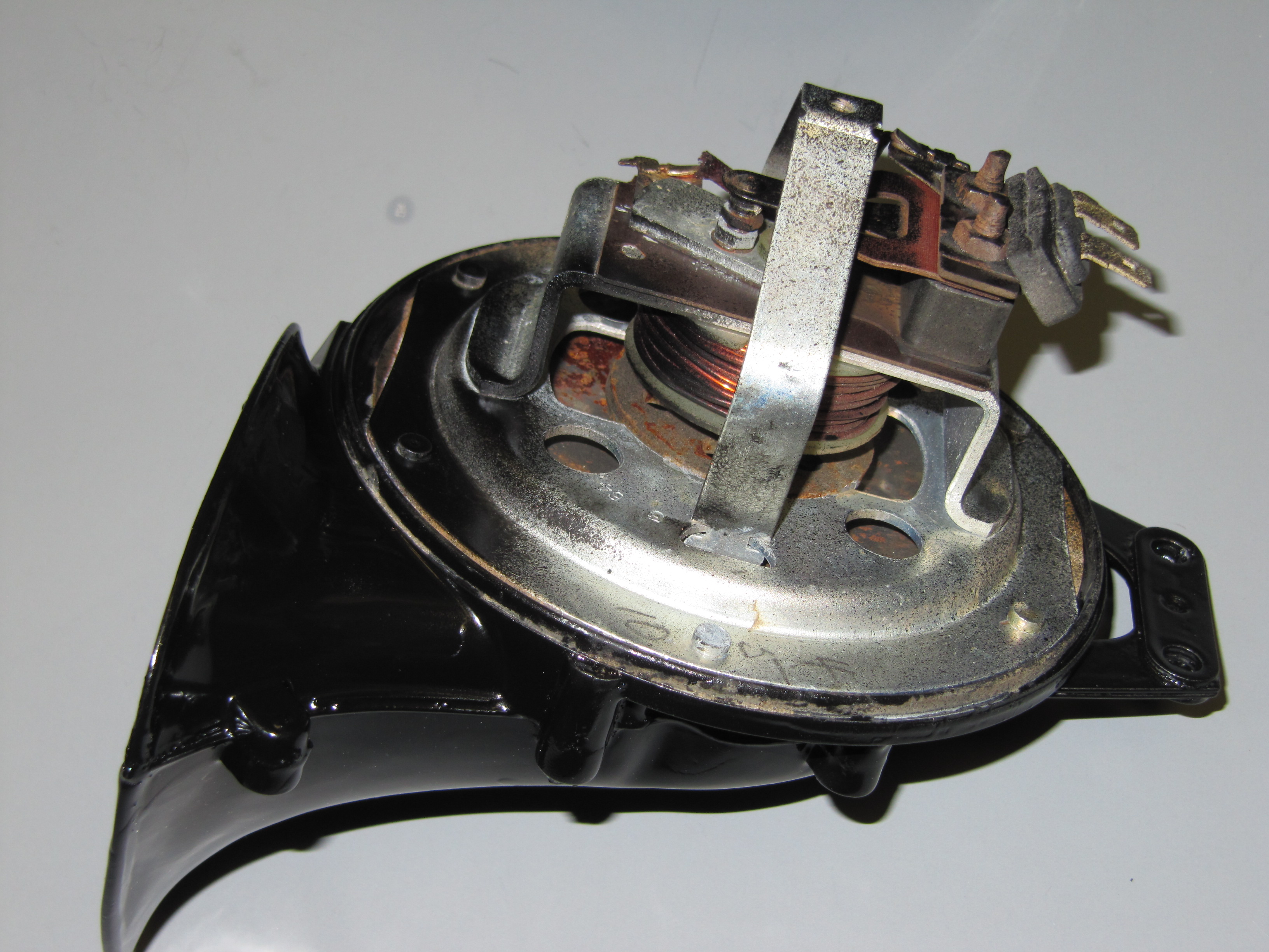
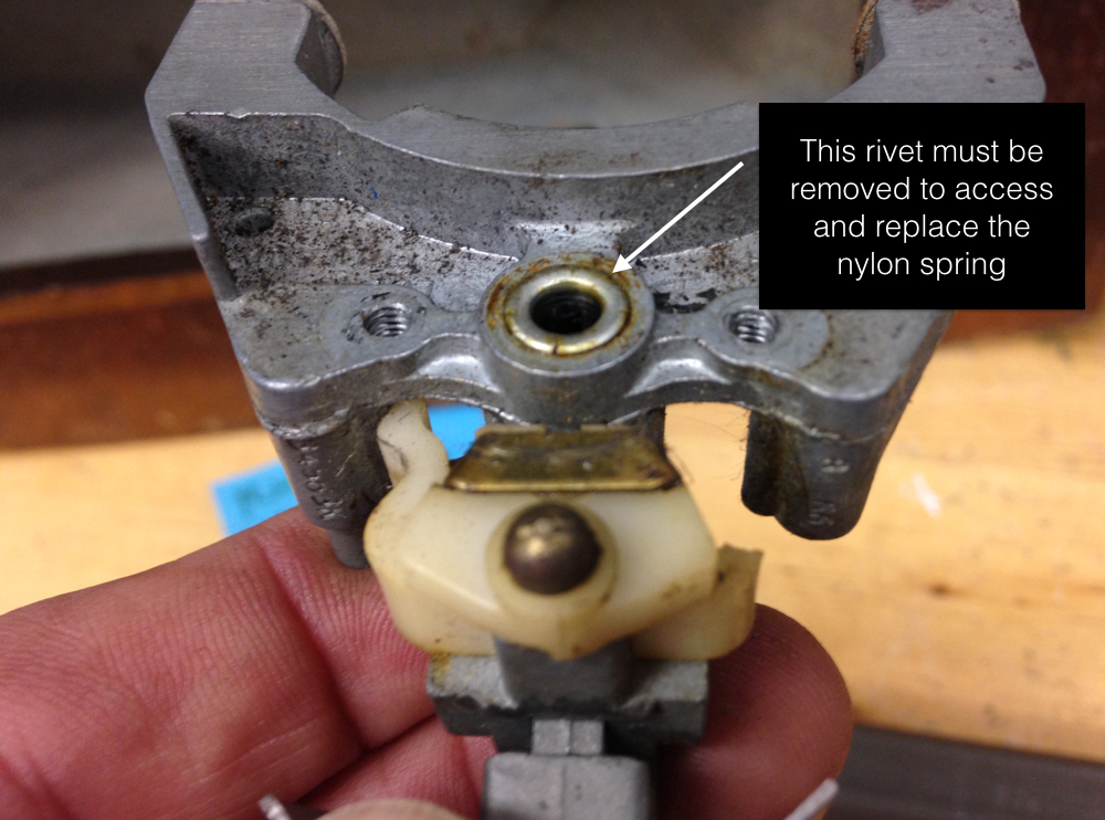
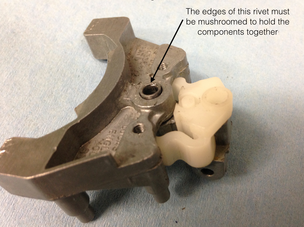
The motor removal was the next step in the disassembly. To get at the three mounting screws for the motor, one must first remove the fan “squirrel cage.” This might normally be done as shown in the image below that was borrowed from another web site. Because more than half of the “fins” in my fan were rusted away, I couldn’t do this. So, I used an air impact wrench which worked like a charm. When the cage or basket is removed, three slotted #10-32 x 1″ machine screws are visible. These can then be held while removing the nuts, rubber and locking washers from the motor side of the case.
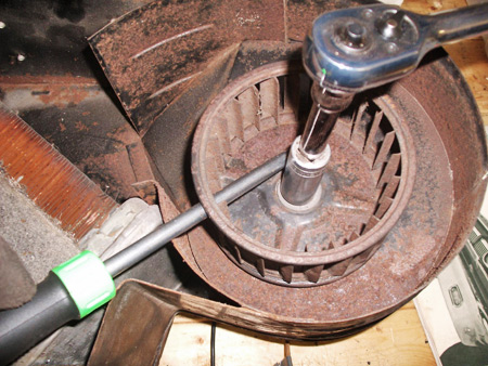
Squirrel Cage Removal
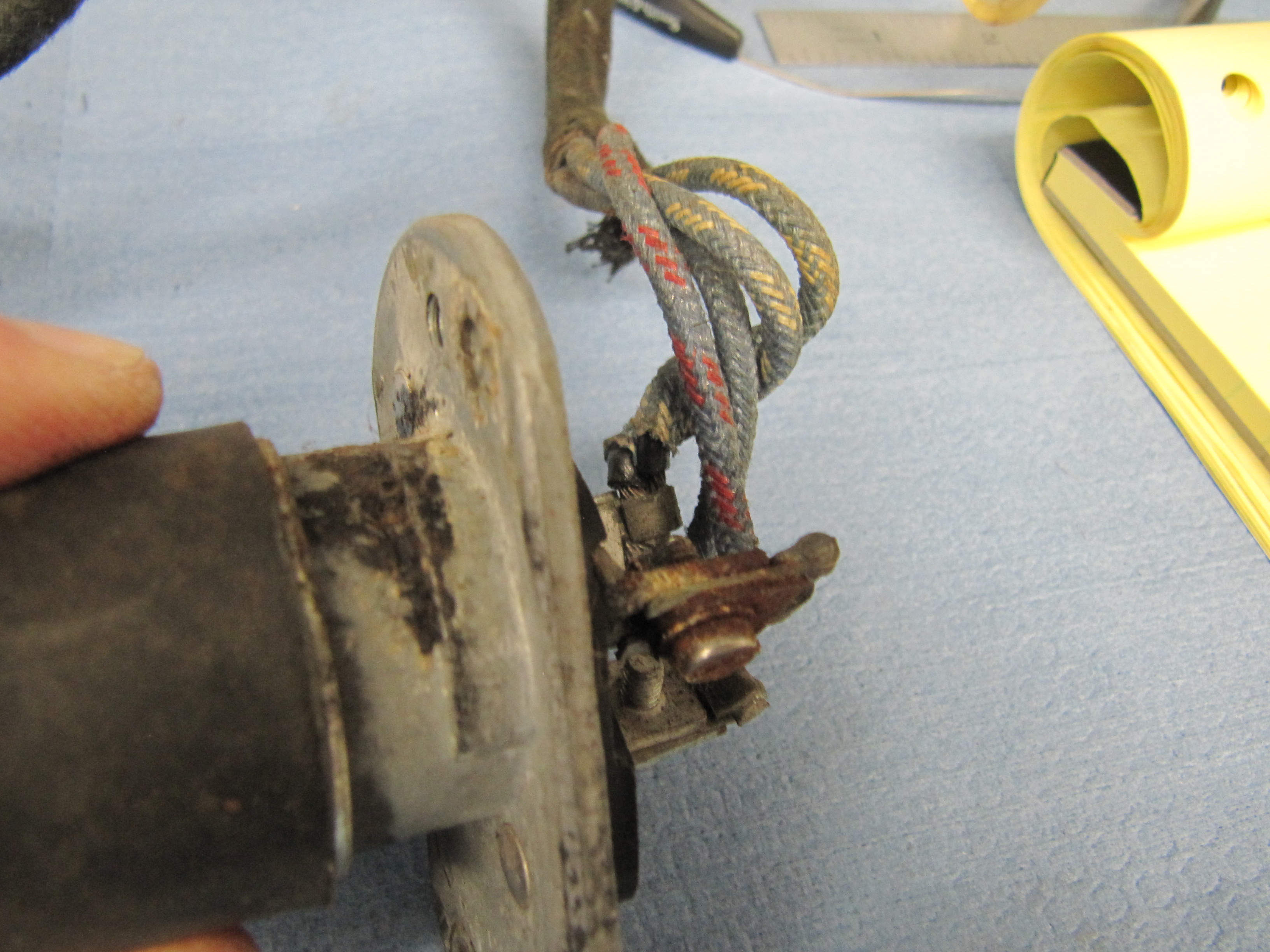
This image shows the mounting nuts and the wiring for the motor. After the three nuts were removed the motor could be lifted away from the case.
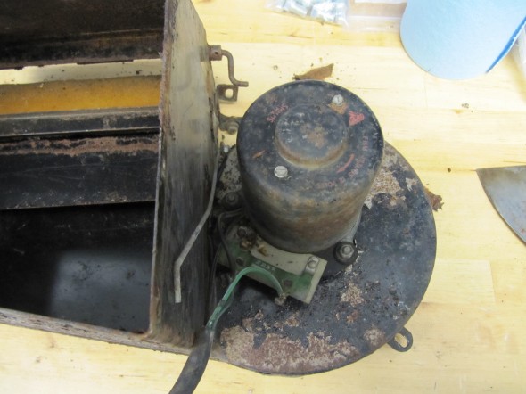
Heater Motor
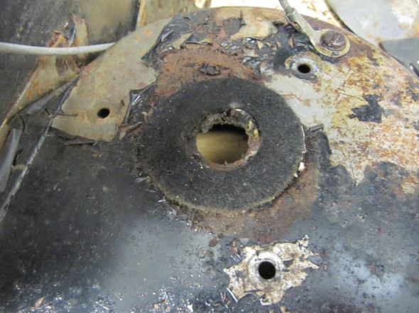
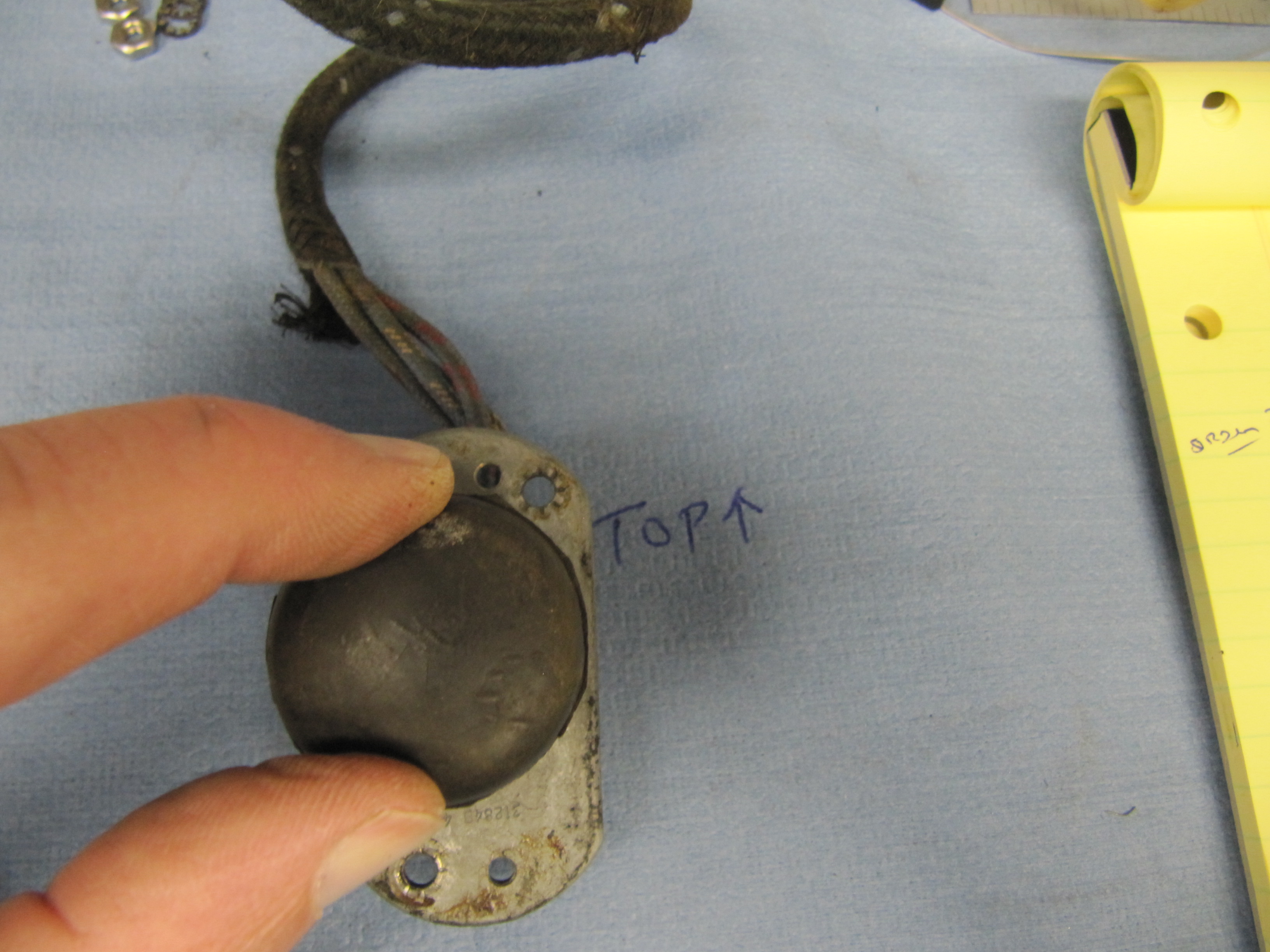
Felt Washer
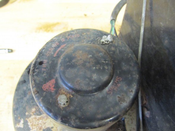
Motor Casing

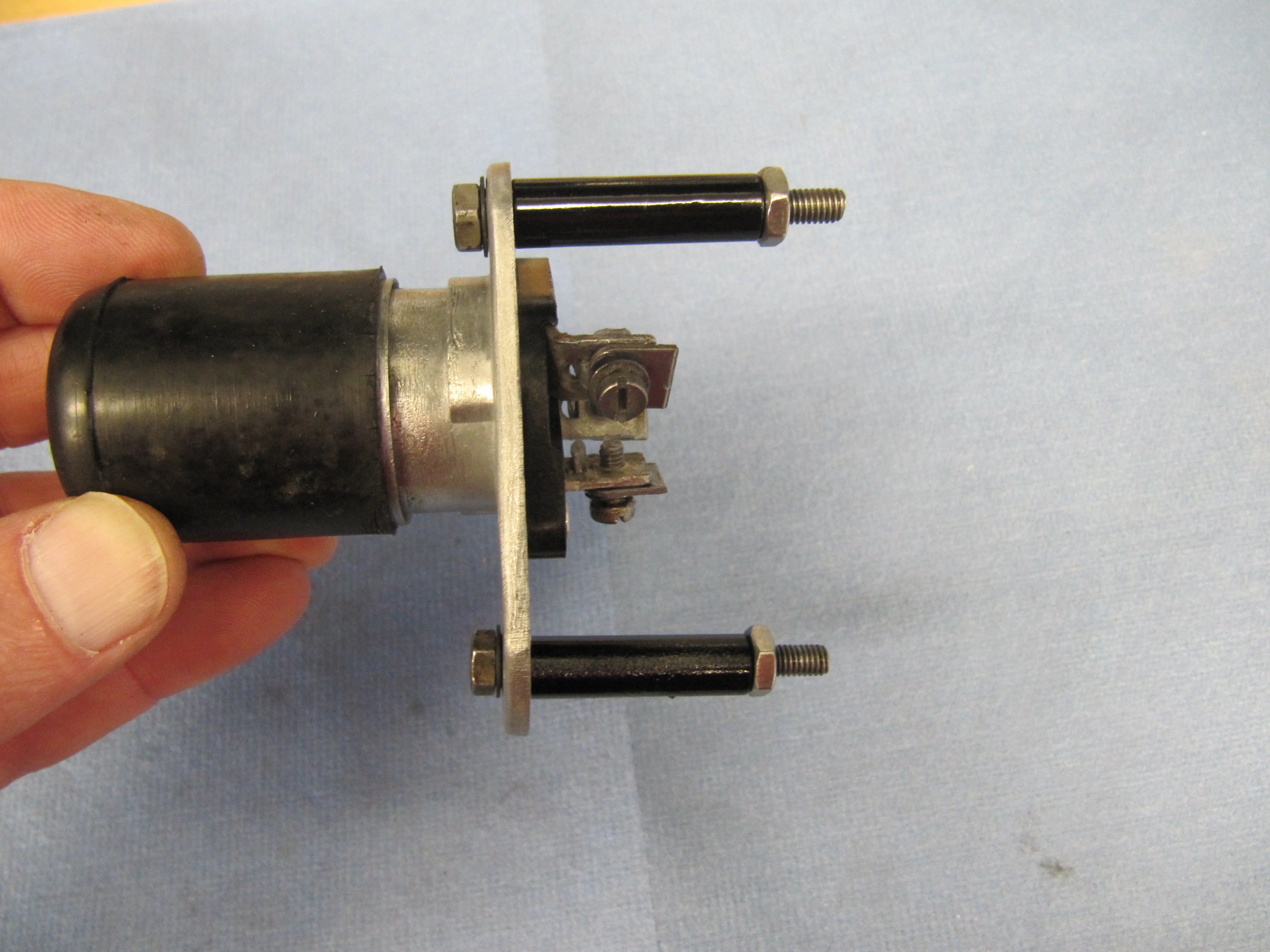
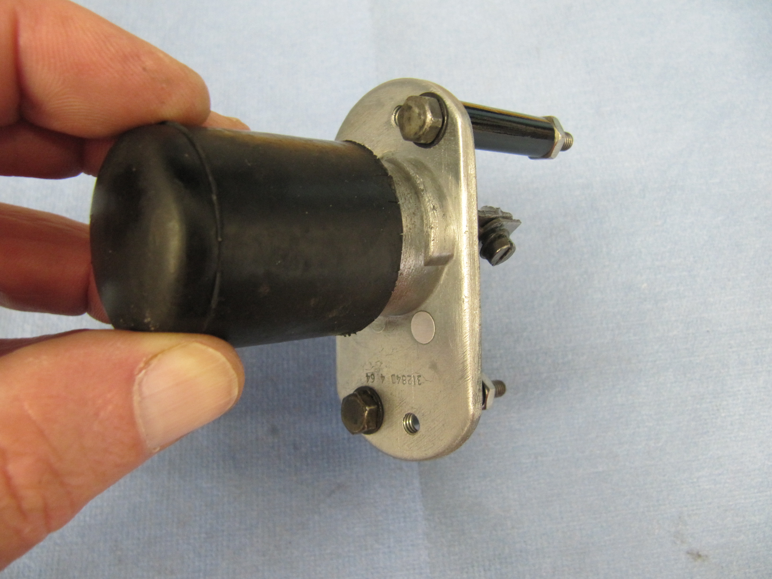
Motor Removed
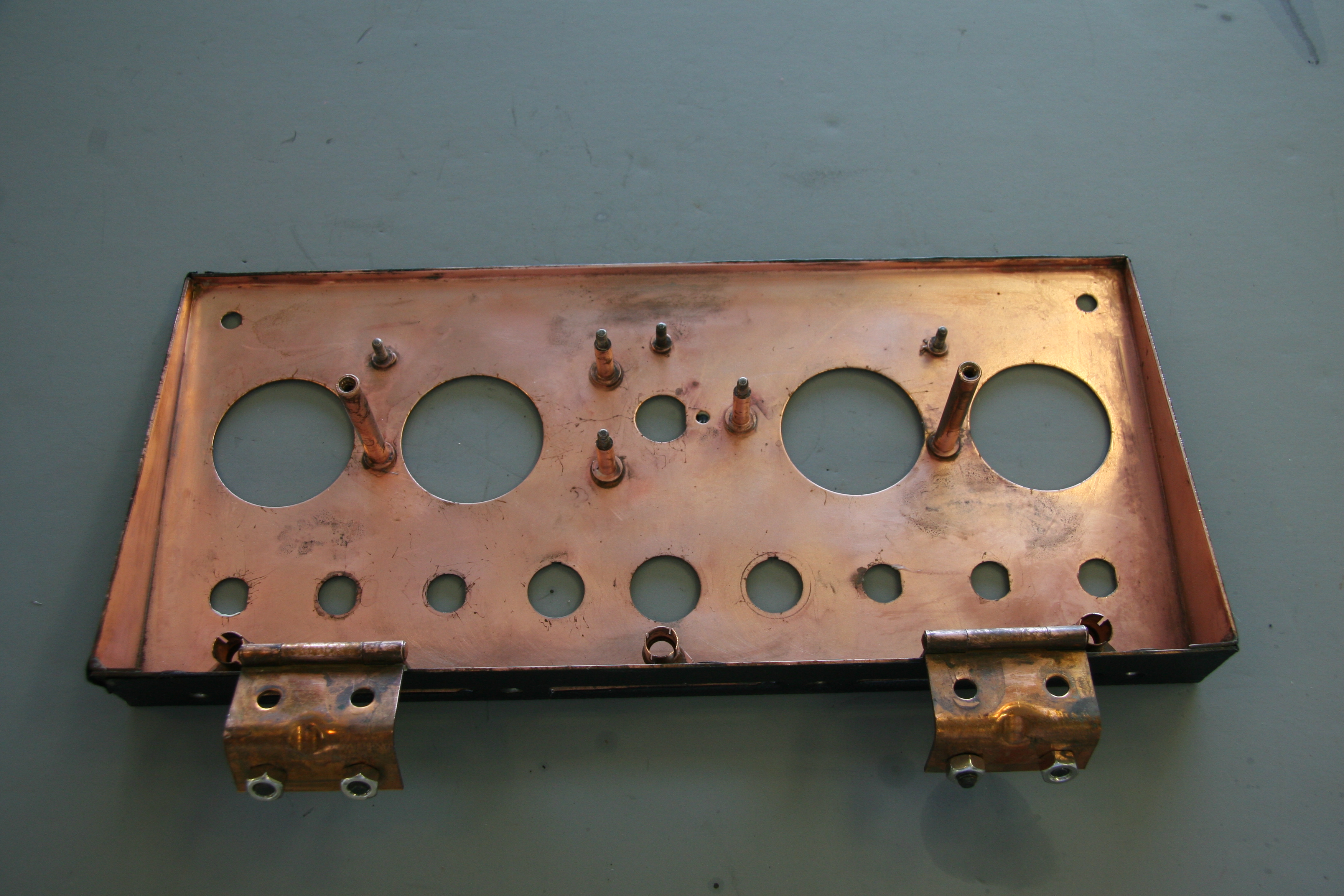
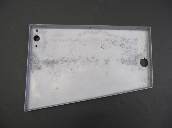
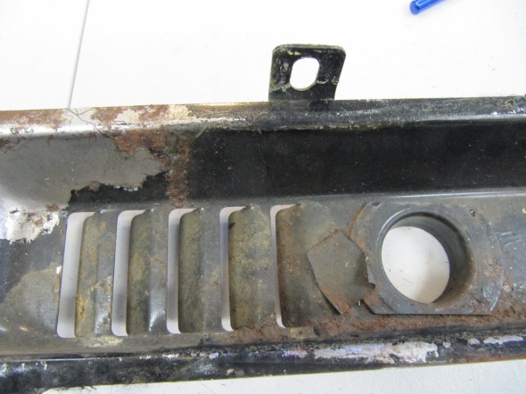
After stripping out the components it was then time to blast the case with aluminum oxide. This process did reveal several rust pinholes. However, the bad news is that the two movable flaps are both “frozen” in place. I have soaked the hinge rods in Kroil to hopefully release the hinges over time.
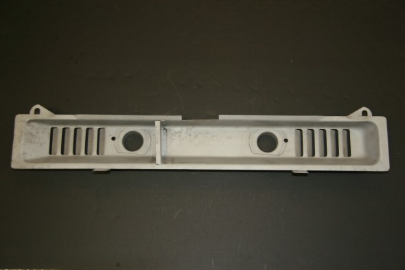
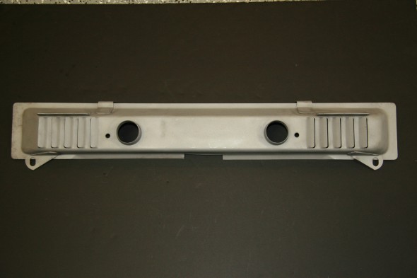
These are a collection of images of the box after blasting. The brown in the images on the flaps is not rust. It is adhesive used to secure the foam pads to the flaps:
Inside View
Air Flaps
Assembly Case
Blower Box
Assembly Case

Blower Box
Air Flap

Air Flap
Air Flap Rod
Heater Lid
Heater Lid
The Kroil did not work so I queried the various email lists and forums. One person suggested heat which I unsuceesfullt tried with a torch. another person suggested a water/molasses solution, but that takes a long time -at least a week. Another suggested electrolysis.
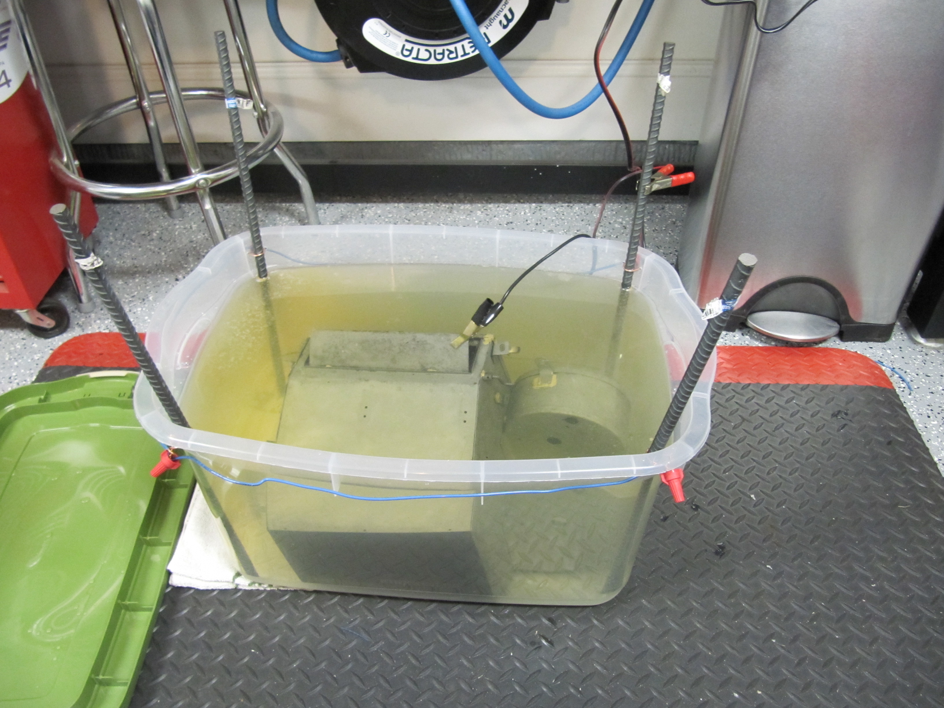
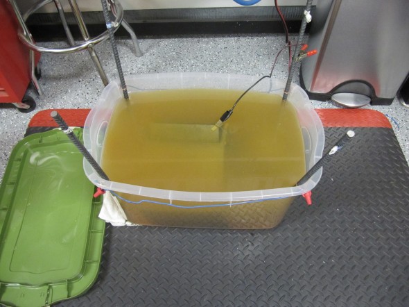
I watched a few YouTube videos on using electrolysis for rust removal, and thought I would give it a try. I emulated this particular video: http://youtu.be/54ADeB6V1rQ
I put the heater box into 14 gallons of water with 14 tablespoons of sodium carbonate. The videos recommend using Arm and Hammer Super Washing Soda, but good luck finding it in a store! I ended up “cooking” baking soda at 200 degrees for an hour to release the carbon dioxide, and thereby turning the sodium bicarbonate into sodium carbonate. Worked like a charm.
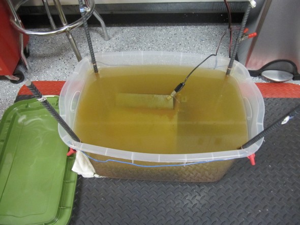
I then attached my battery charger and let the magic begin. I put the box in the solution at 9:15 PM and after two hours I was surprised at how much the water color had changed from clear to rust given how clean the box already was from blasting. The solution just gets into places the aluminum oxide blast abrasive cannot. I then let it all sit until about 8:00 AM this morning.
I cleaned up my mess and put the box on the work table expecting to be disappointed, but I was not. One flap started working immediately, needing little coercion. The second required some pushing and pulling and a little lubrication but it now functions properly as well!
I would use this process again in a minute. Very inexpensive and easy. One more original Jaguar part saved. I have a little pitting to fill with body filler, but otherwise should be a very serviceable unit.
Try it – you will like it.
In the images below the light colored water image was at 9:00 PM almost exactly when the Box went in the solution. The darker colored water image was taken at 8:00 AM the next morning when the Box was removed from the solution.

9PM Start Bath
11PM Bath
8AM Finish Bath
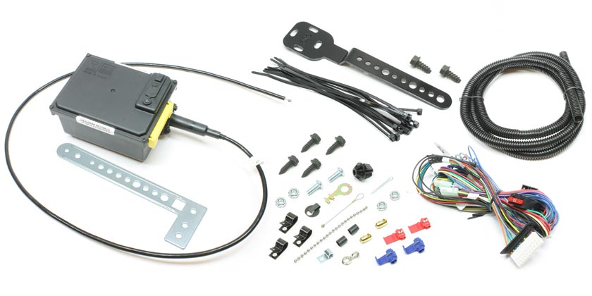
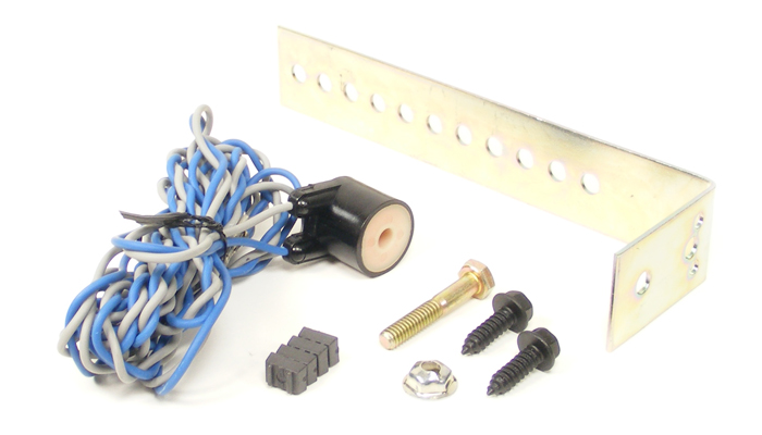
The Clayton Classics Upgrade
I ordered the upgrade kit for the MK2 heater from Clayton Classics in the UK.
Phil Beveridge.
Manager.
Clayton Classics.
Hunter Terrace,
Fletchworth Gate,
Burnsall Road,
Coventry.
CV5 6SP
Tel: +44 (0)24 7669 1916
Fax: +44(0)2476691969
E-mail:phil@claytonclassics.co.uk
-OR-
Liz Chandler
Sales Adminstrator
Clayton VS Limited
Phone: 02476 691916
email: salesadmin@claytoncc.co.uk
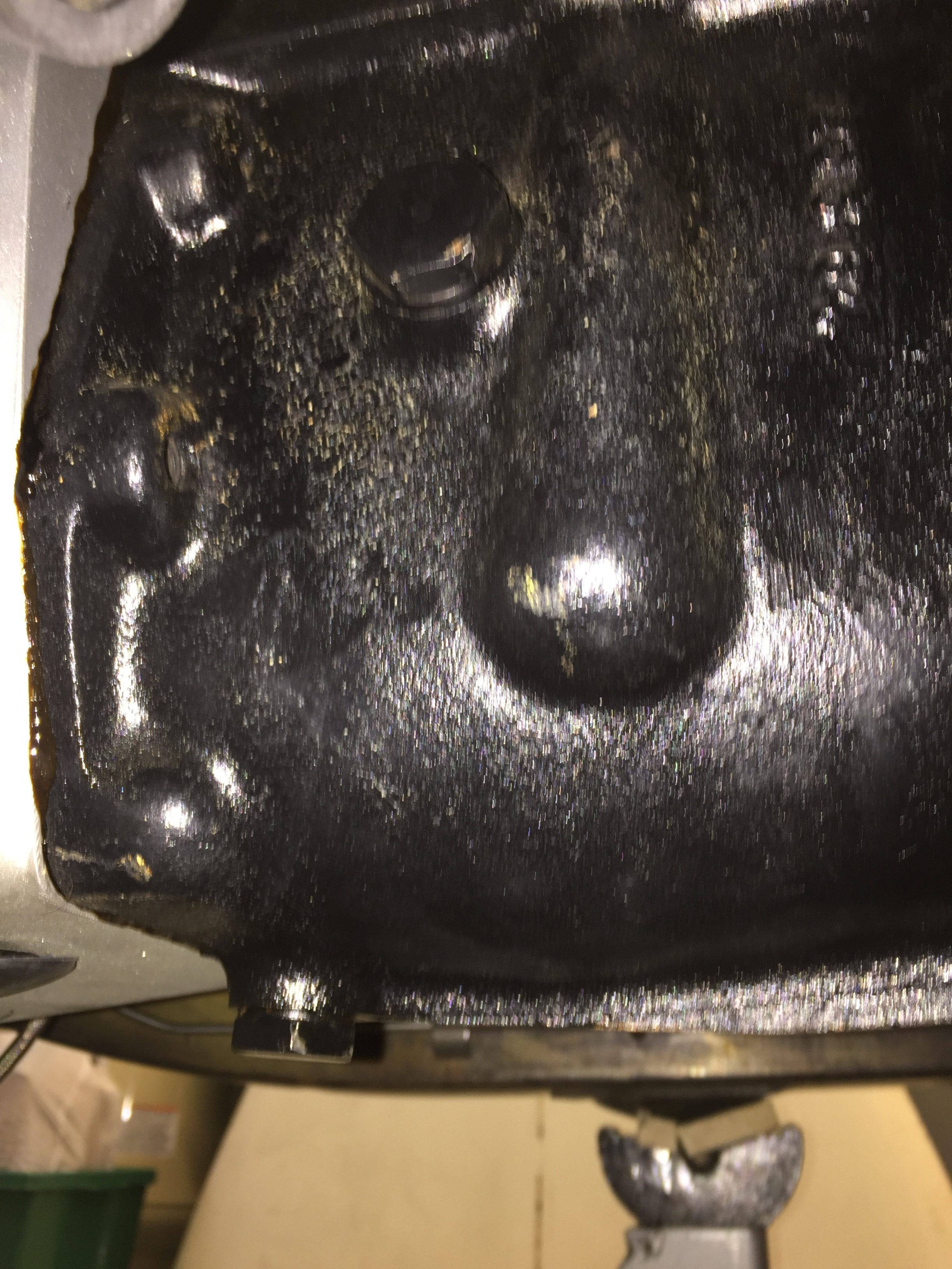
While awaiting delivery, I had the bottom of the heater box braised to take care of the worst of the pin holes in the bottom of the blower body. The kit arrived with everything necessary to enhance the performance of the original box.
Clayton provided pdf versions of two articles from Jaguar World Monthly that detailed, through photographs and narrative, the removal and dismantling of the original heater box assembly as well as the modifications required. The article was begun and completed over two month’s publication of the magazine. They also included a pdf of their own assembly directions. These are referenced below:
Jaguar Mk2 Heater upgrade installation instructions
classic workshop XK120 Heater Mk2 Heater dec09
Mk2 Heater Upgrade classic workshop jan10
Four modifications to the original box are required.
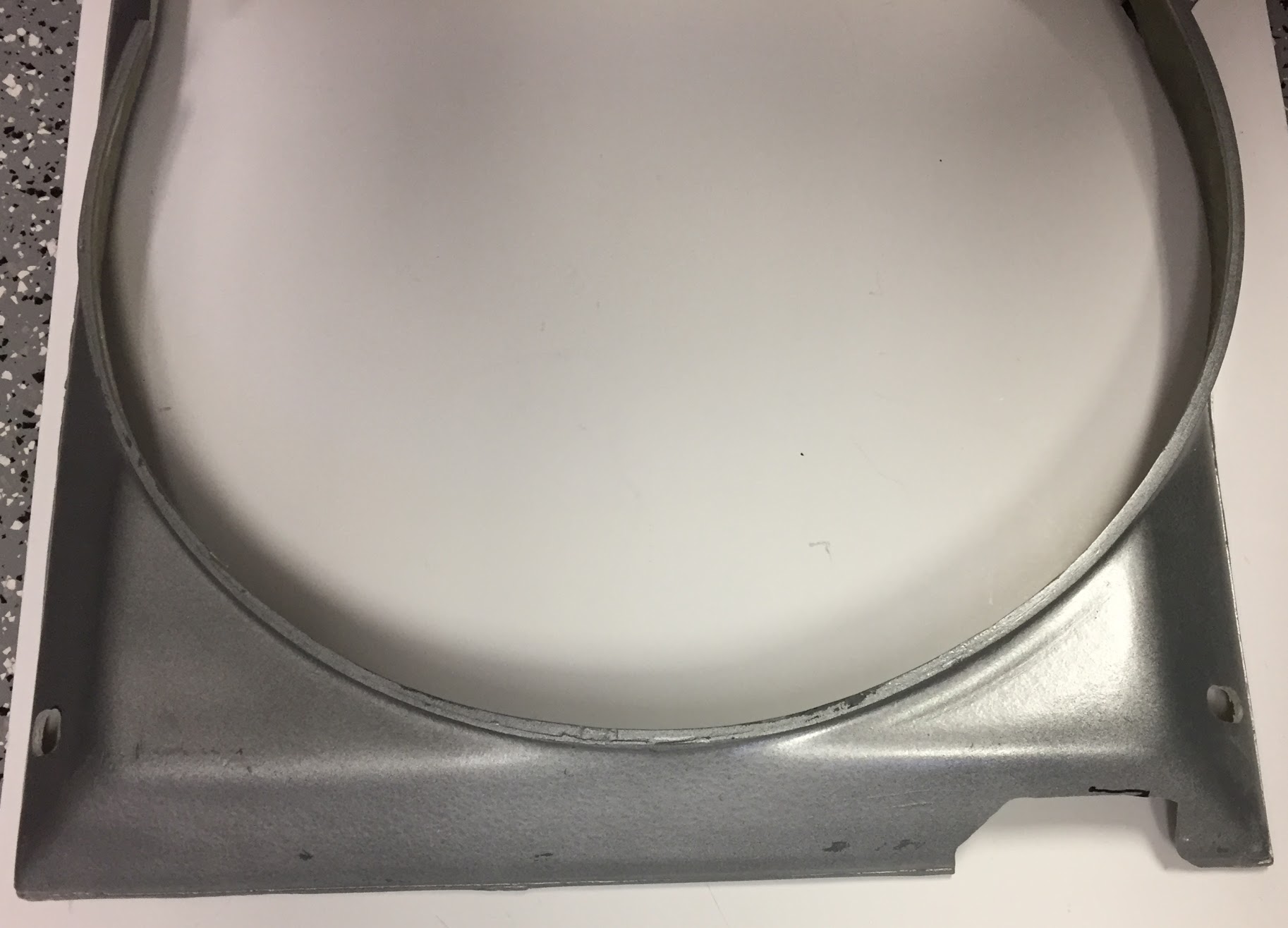
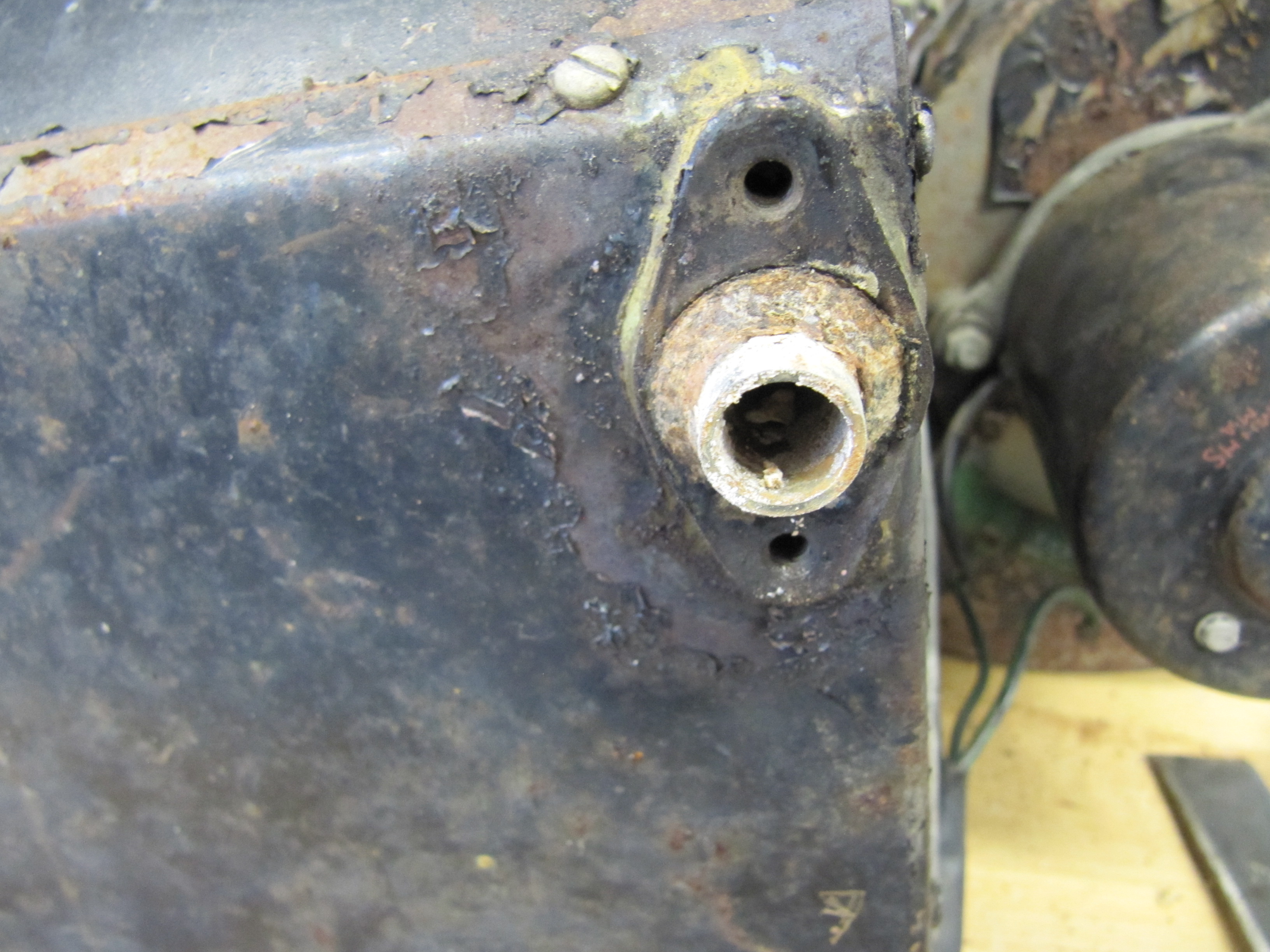
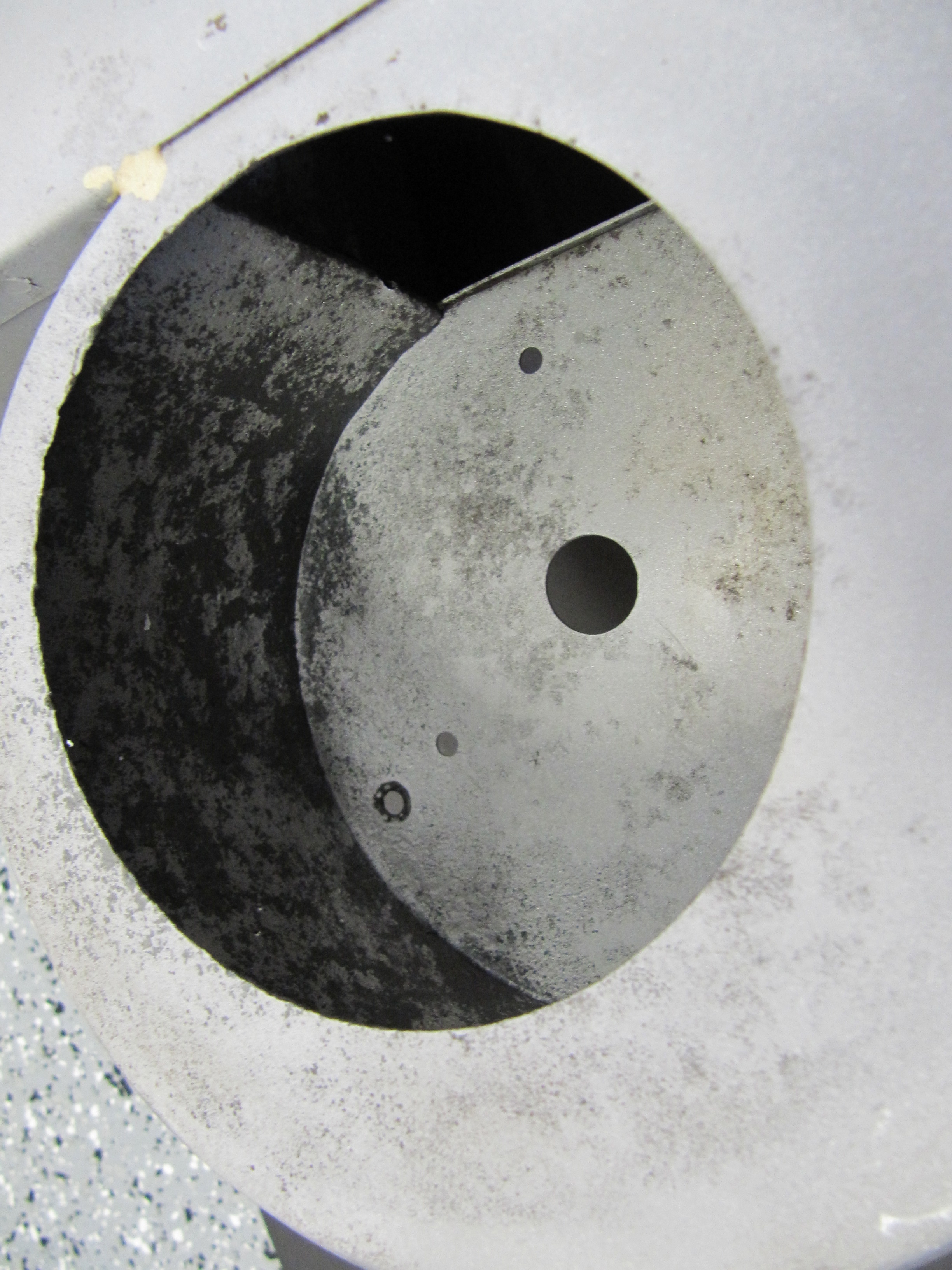
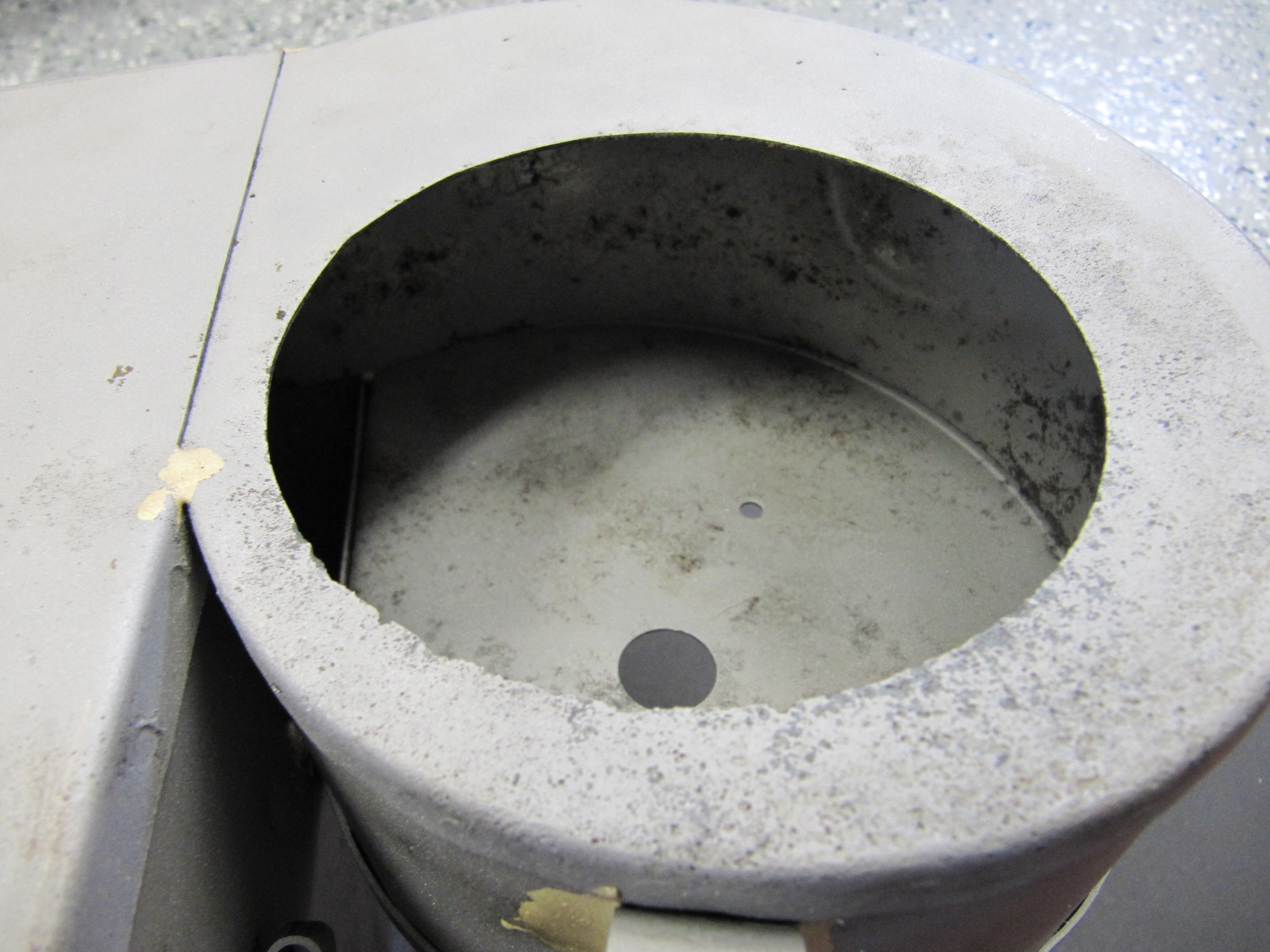
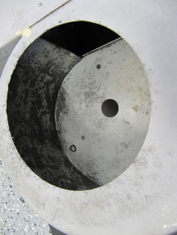
- The air inlet opening in the blower casing must be increased in diameter to 120mm to permit the introduction of the larger fan supplied by Clayton. A perfect cut is not required as the surface will be covered by the seal between the heater and the dash at volute.
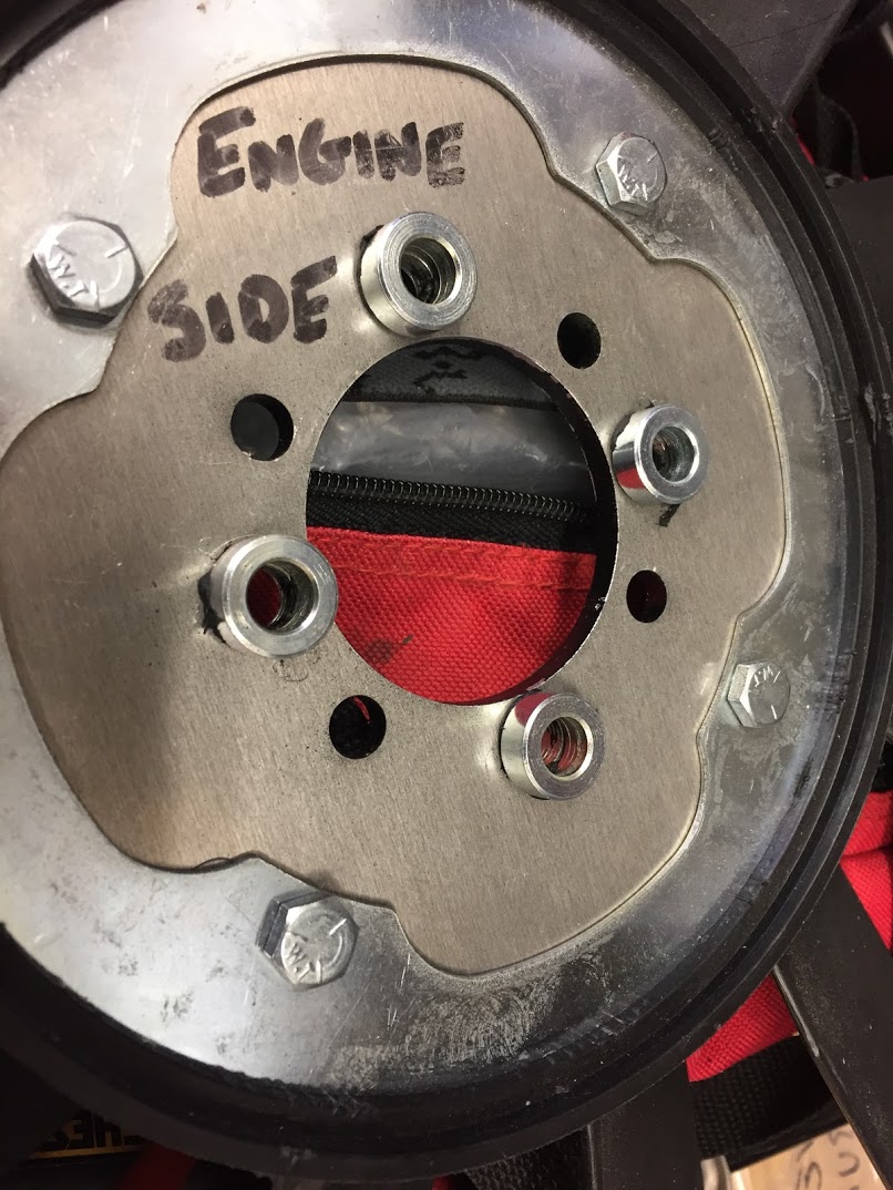
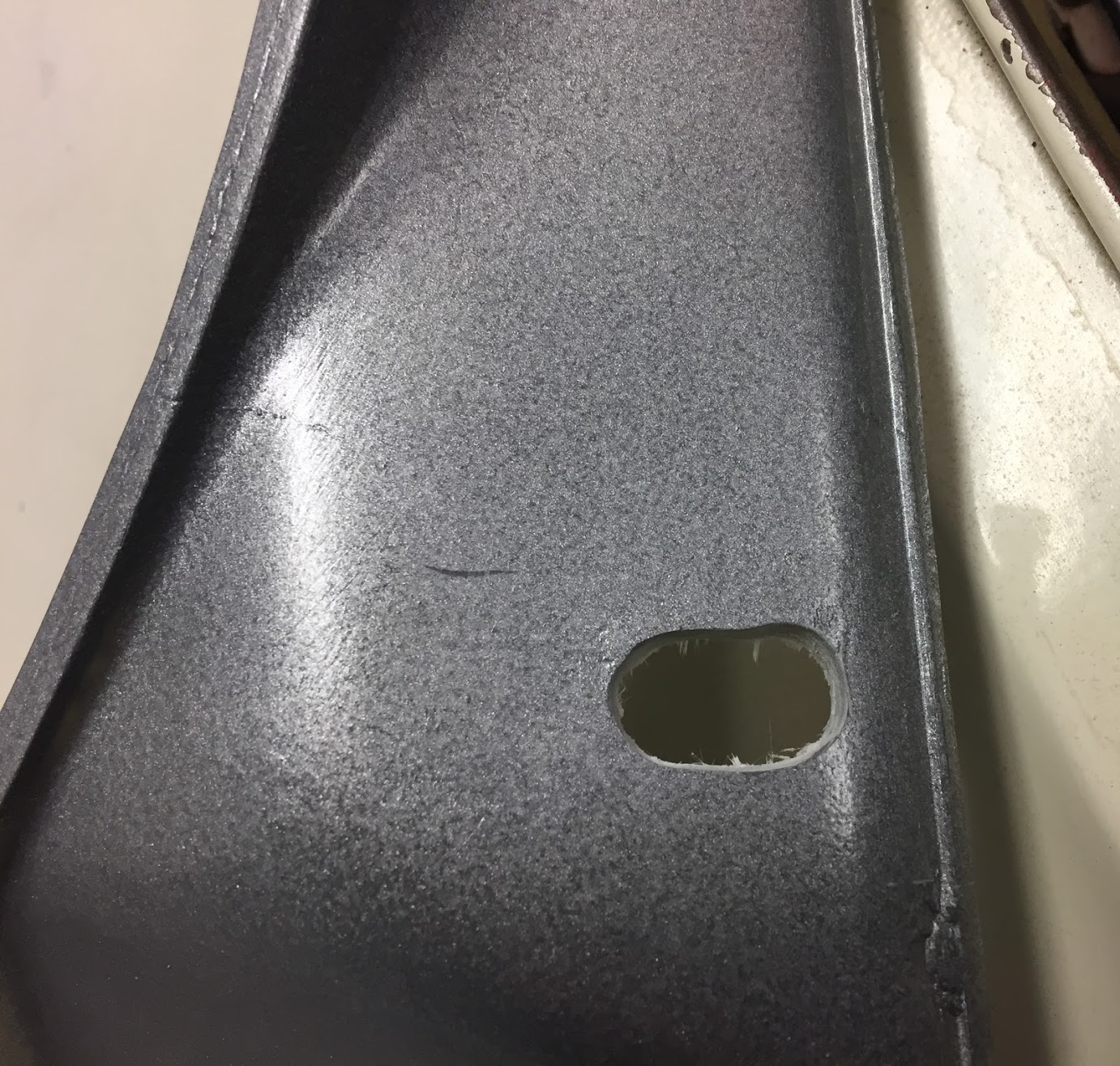
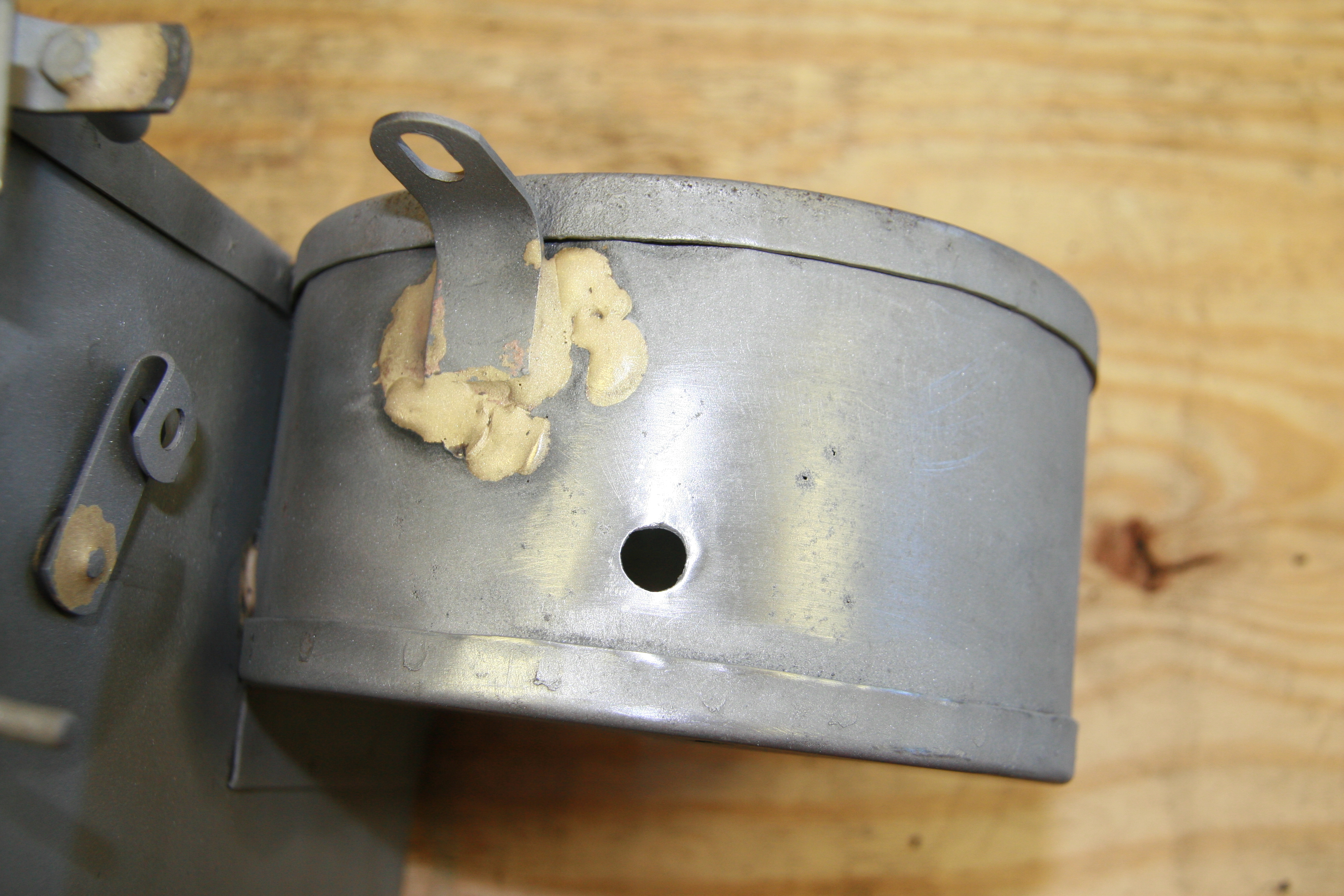
- A 10mm hole was drilled into the blower casing to permit allen wrench access to the motor shaft to tighten the fan to the shaft. A rubber plug covers the hole after the fan is installed.
- Three small holes for self-tapping screws to secure the motor mounting bracket needed to be drilled in the blower casing.
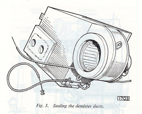
- Clayton suggests the original design that incorporated the inner flap was simply a bad design that permitted the dilution of hot air with cold before entering the cabin. Their recommendation is to seal the flap with silicone and to disconnect the flap controls so that the flap remains permanently closed.
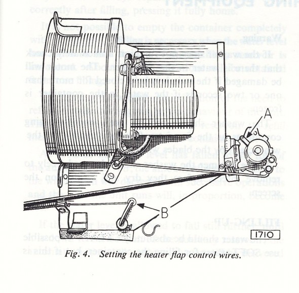
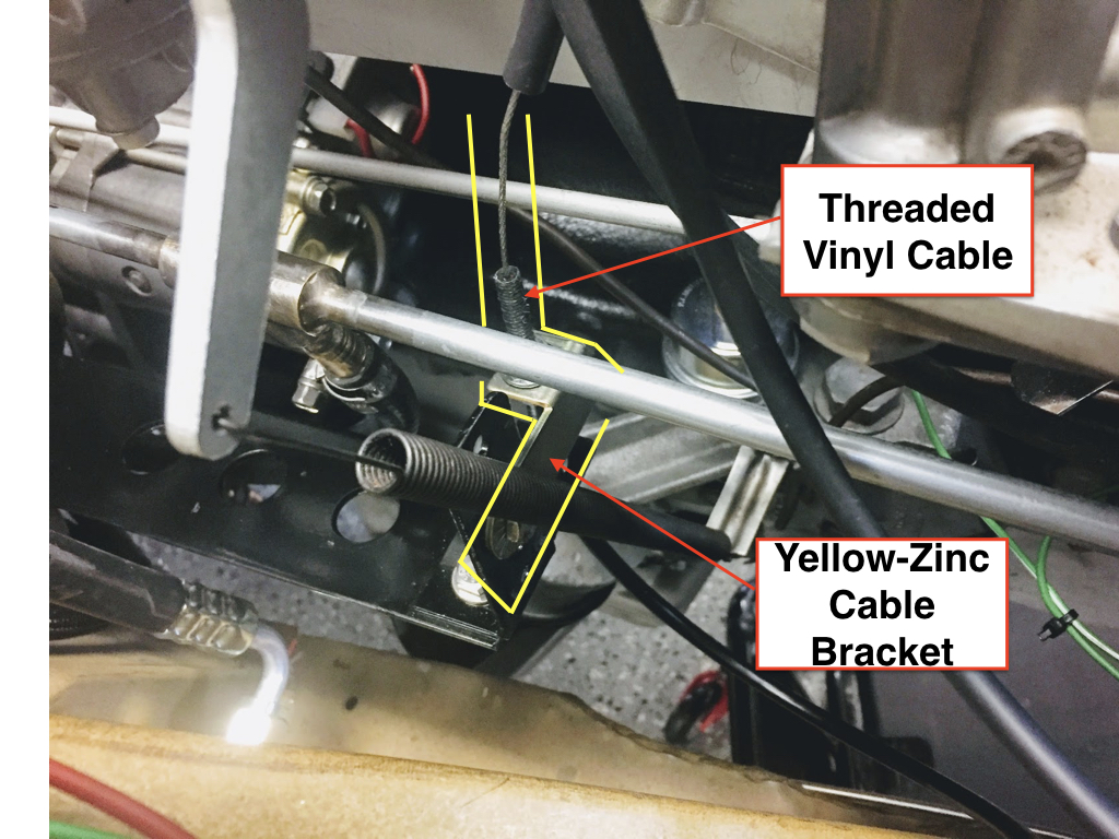
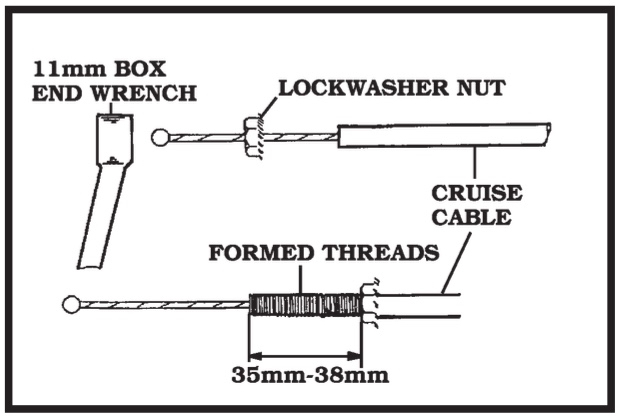
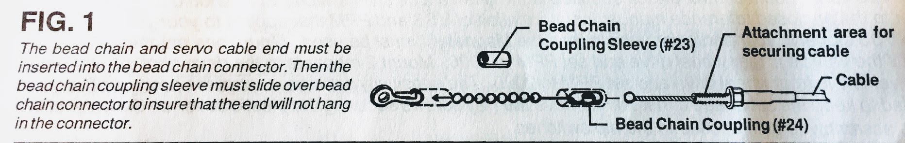
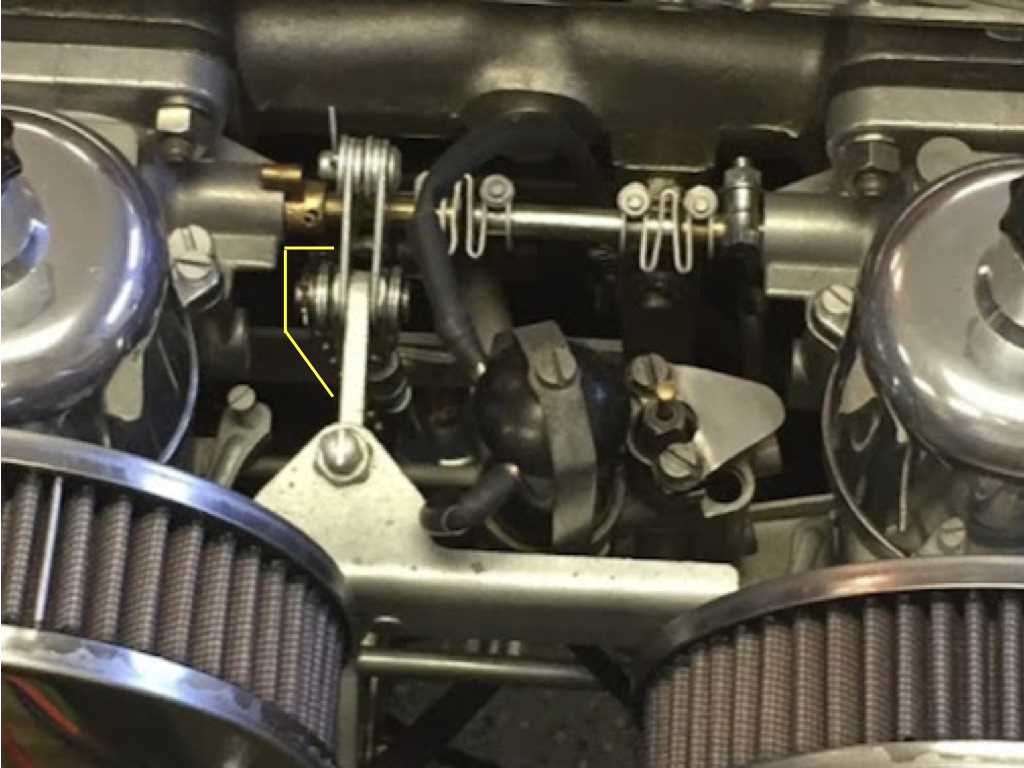
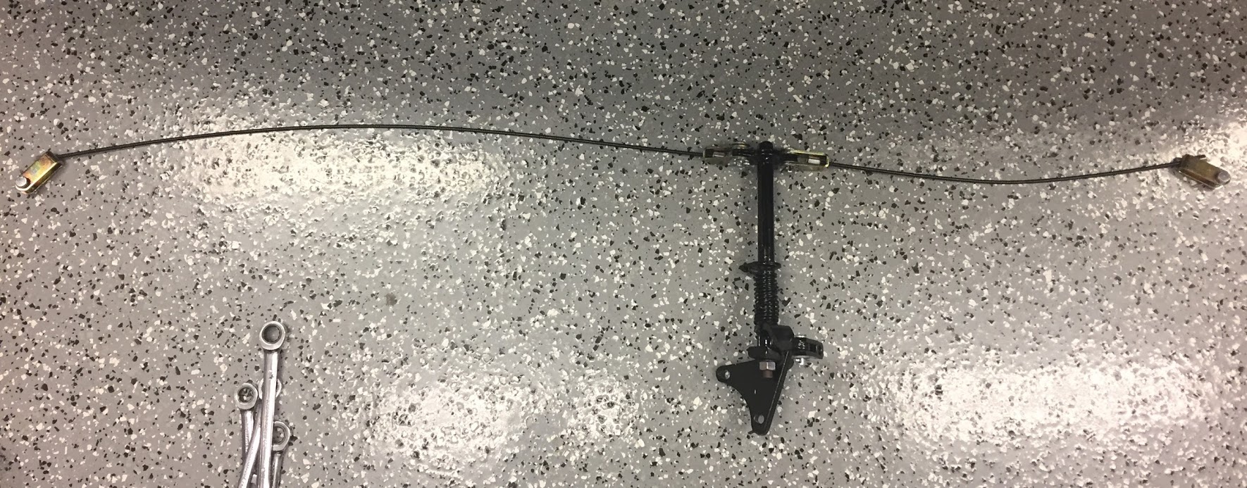
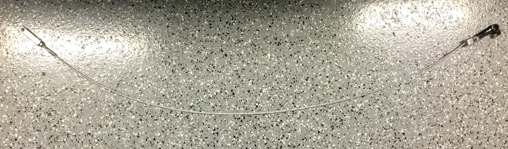
Heater Flap Control Cables
120mm Diameter Heater Box Modification to Allow Larger Fan

Access Hole for Fan Shaft Allen Screw
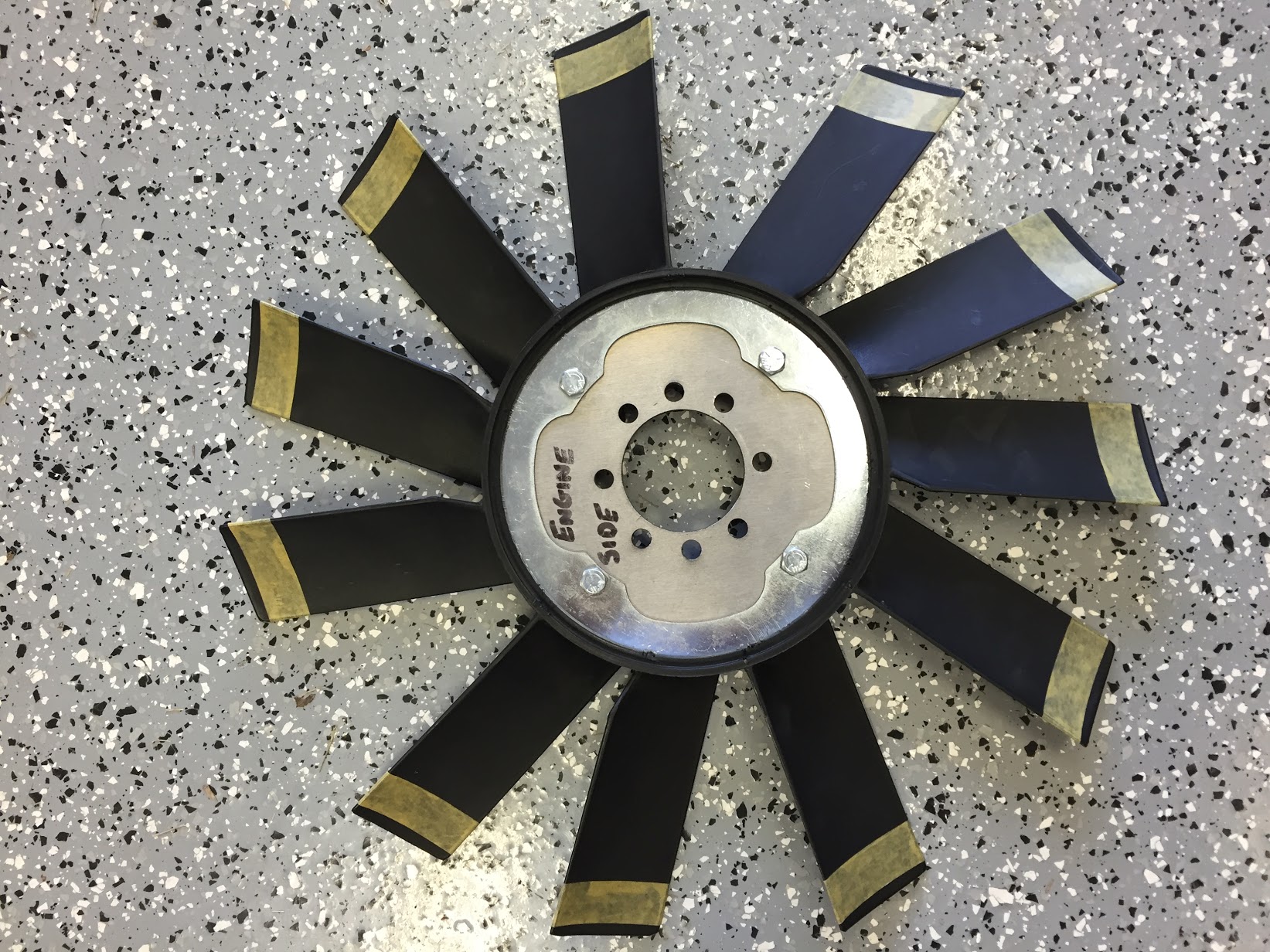
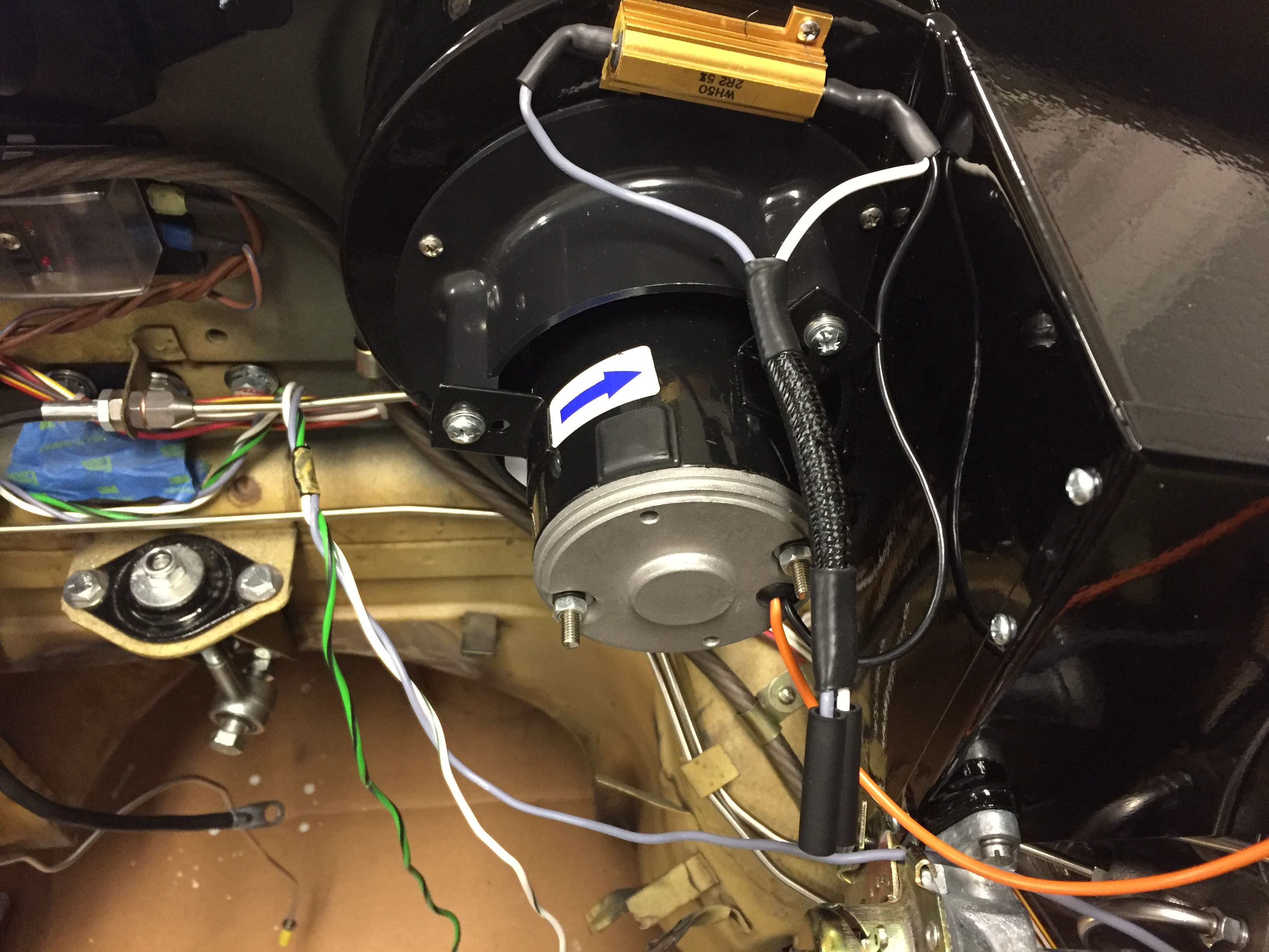
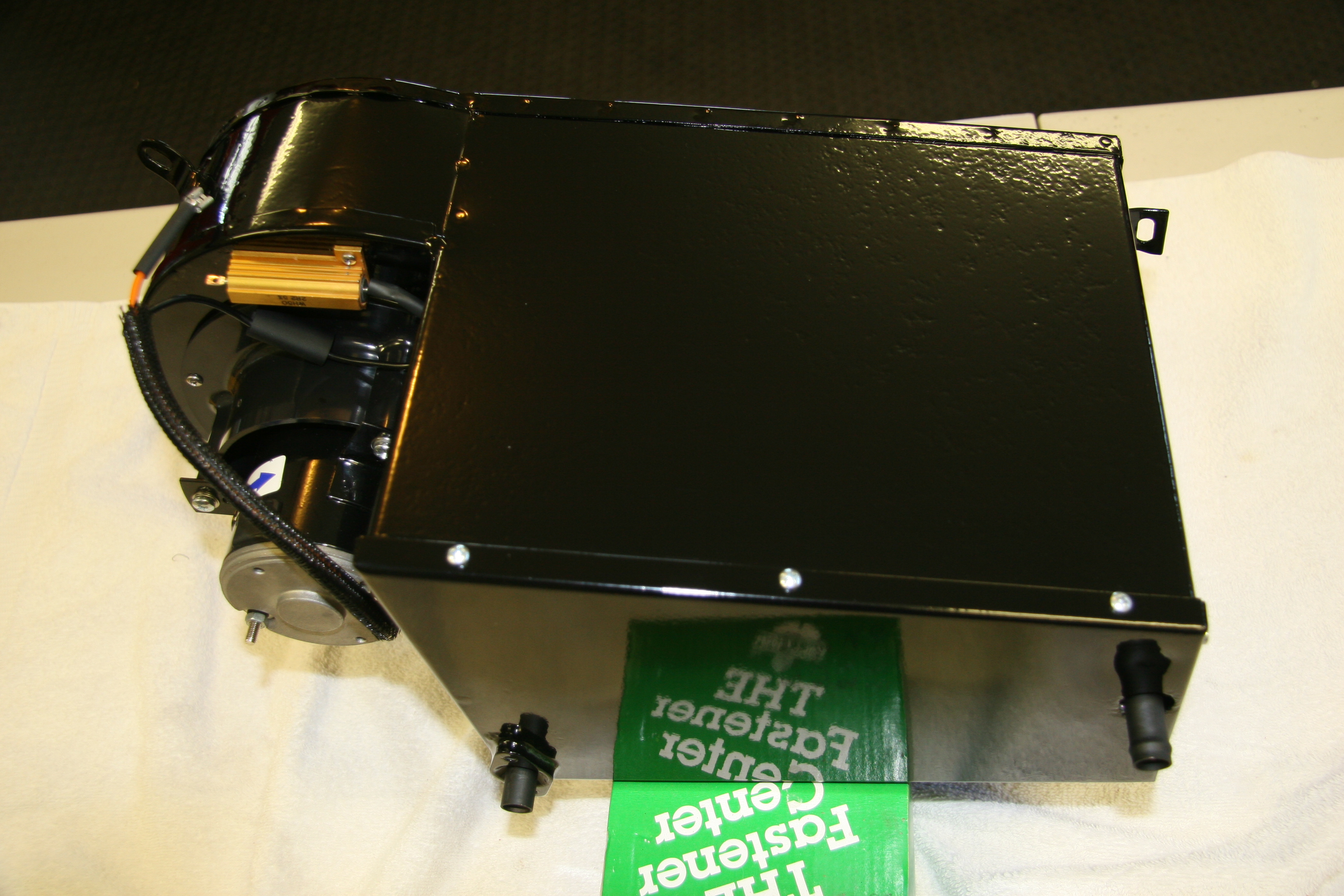
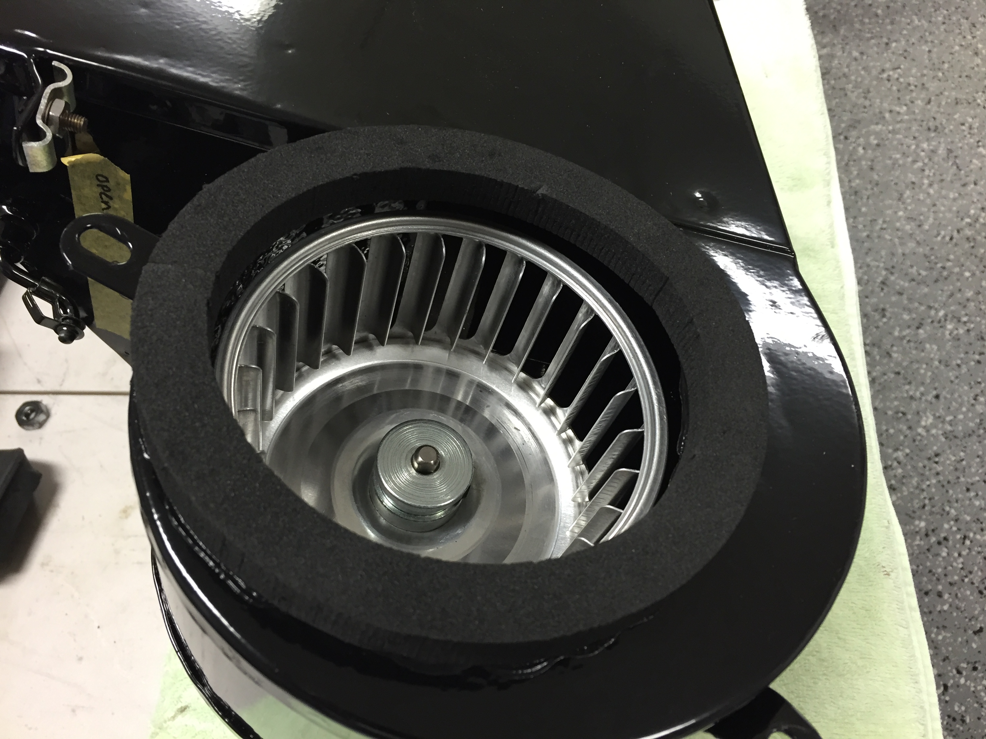
Clayton Motor Upgrade Installed
I completed the first three modifications before powder coating the entire box.
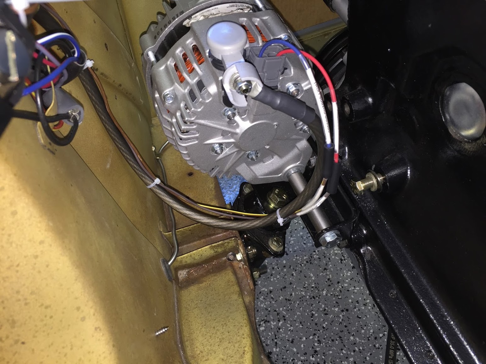
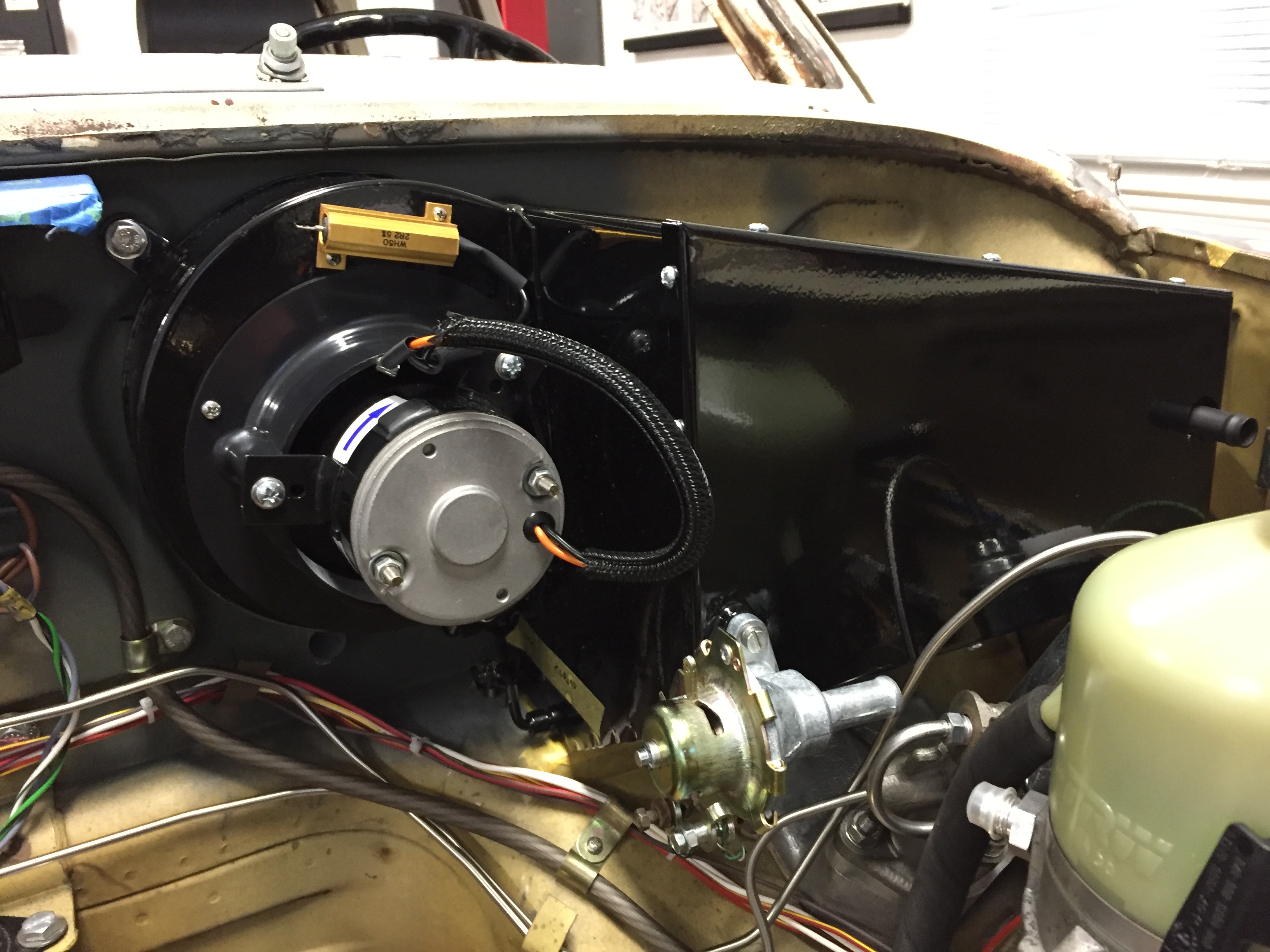
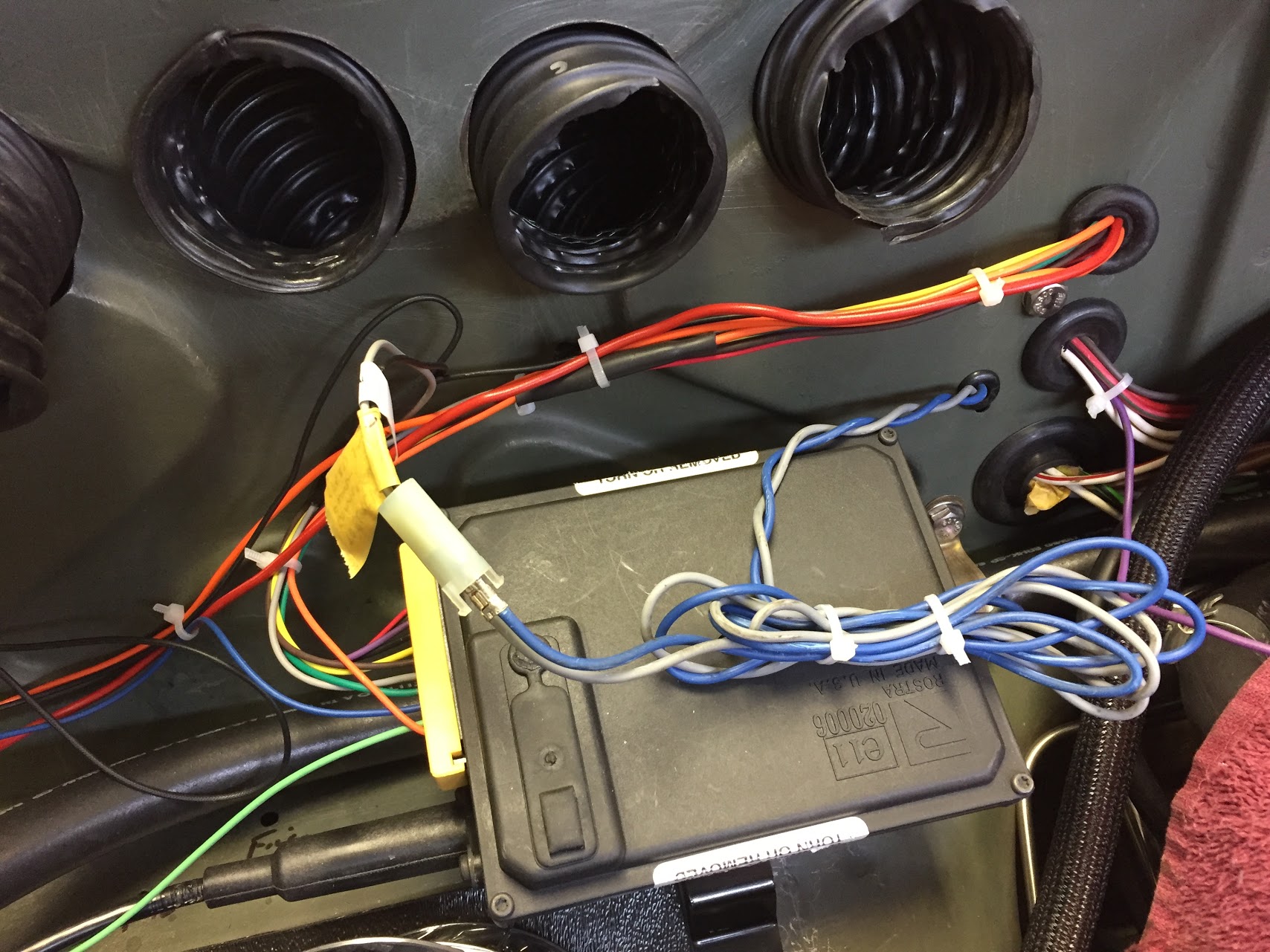
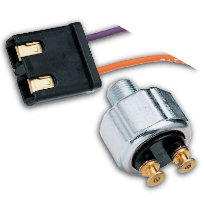
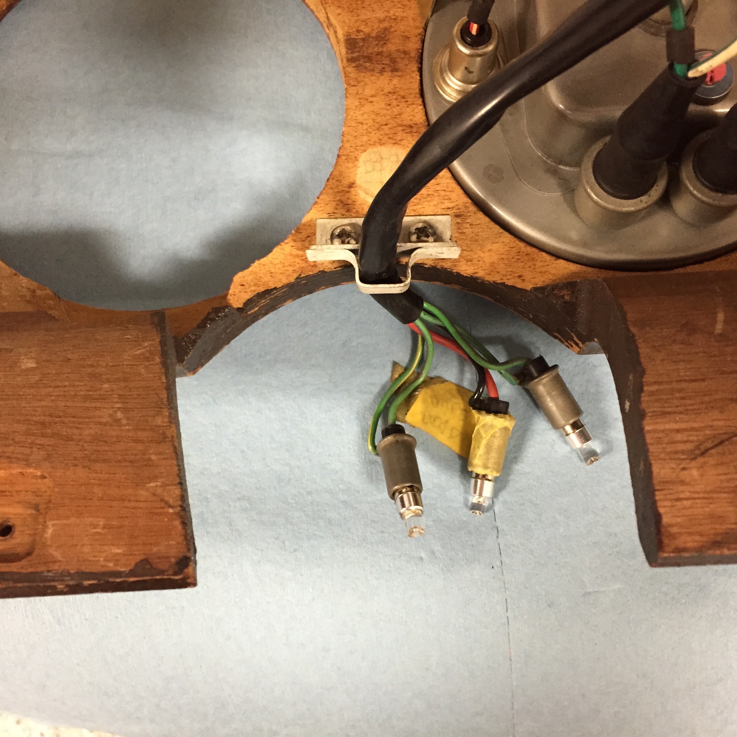
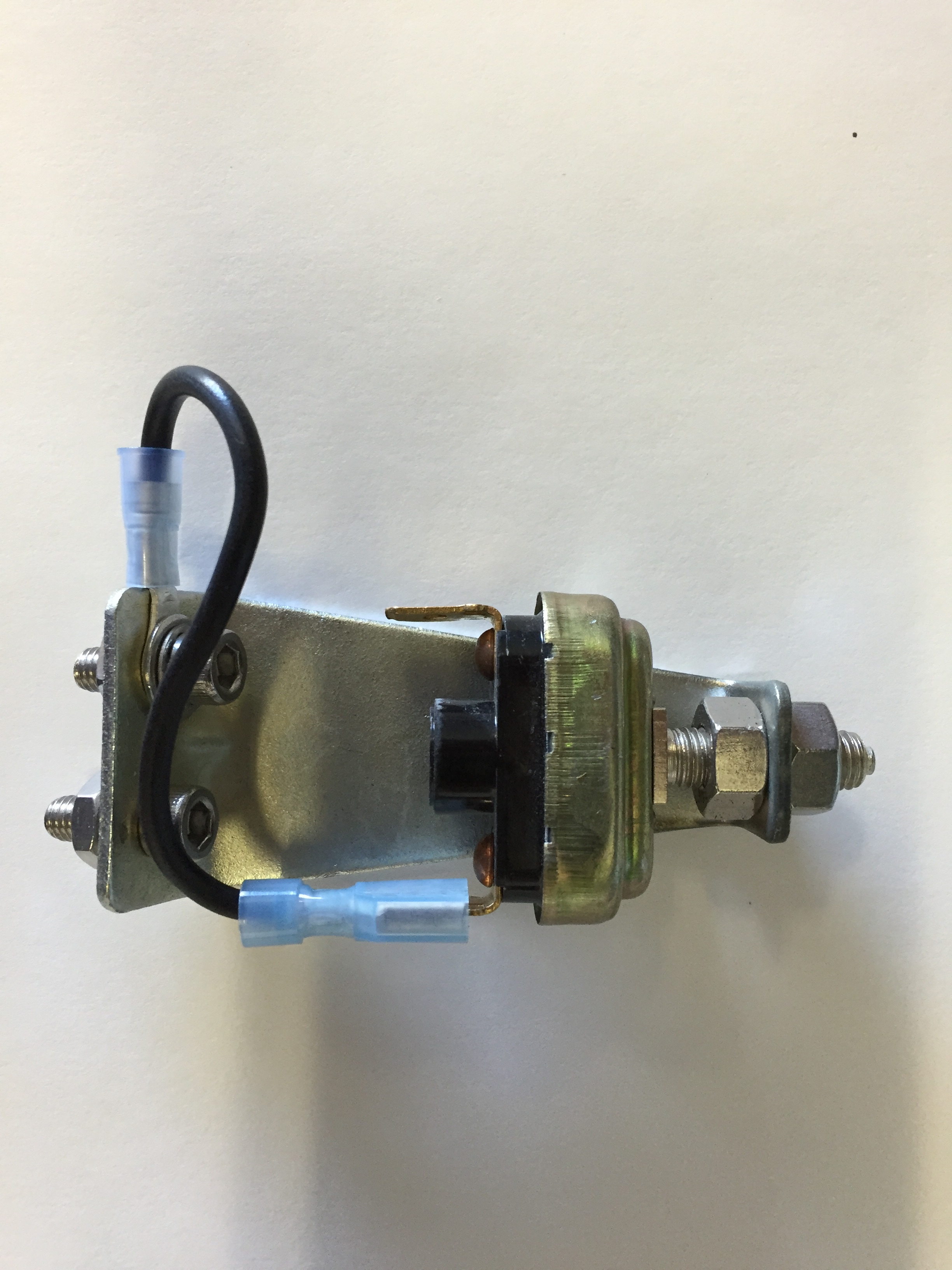
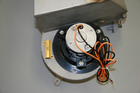
I test fit all of the components and then tested the electrical wiring and connections. The new motor was wired for a positive ground car. To have the fan move in the proper counter clock-wise direction, these wires must be reversed in a negative ground car.
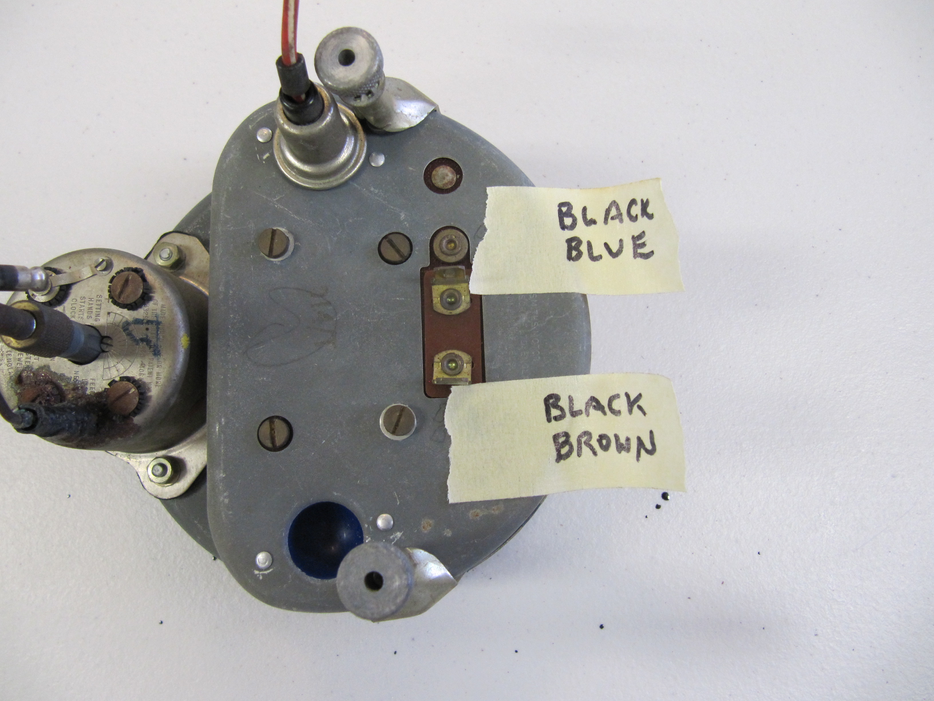
[NOTE]: My wire colors are different than the original wiring scheme.
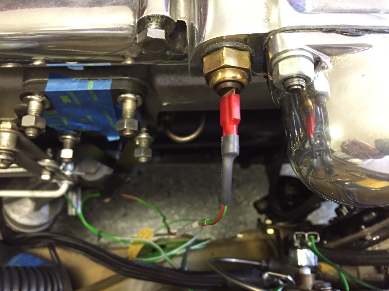
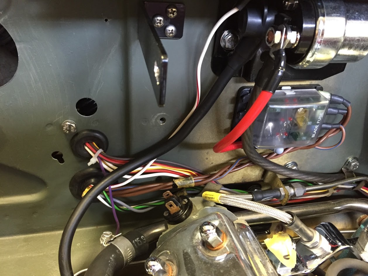
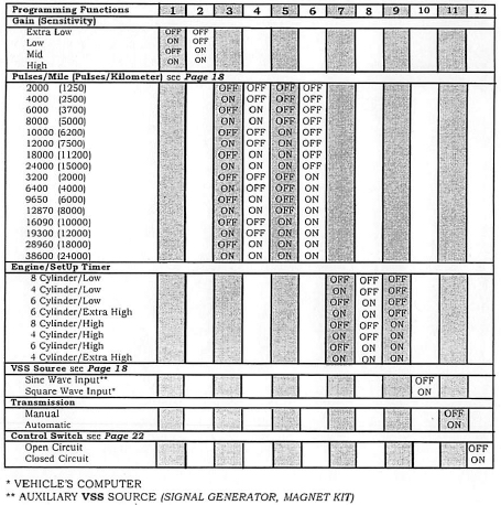
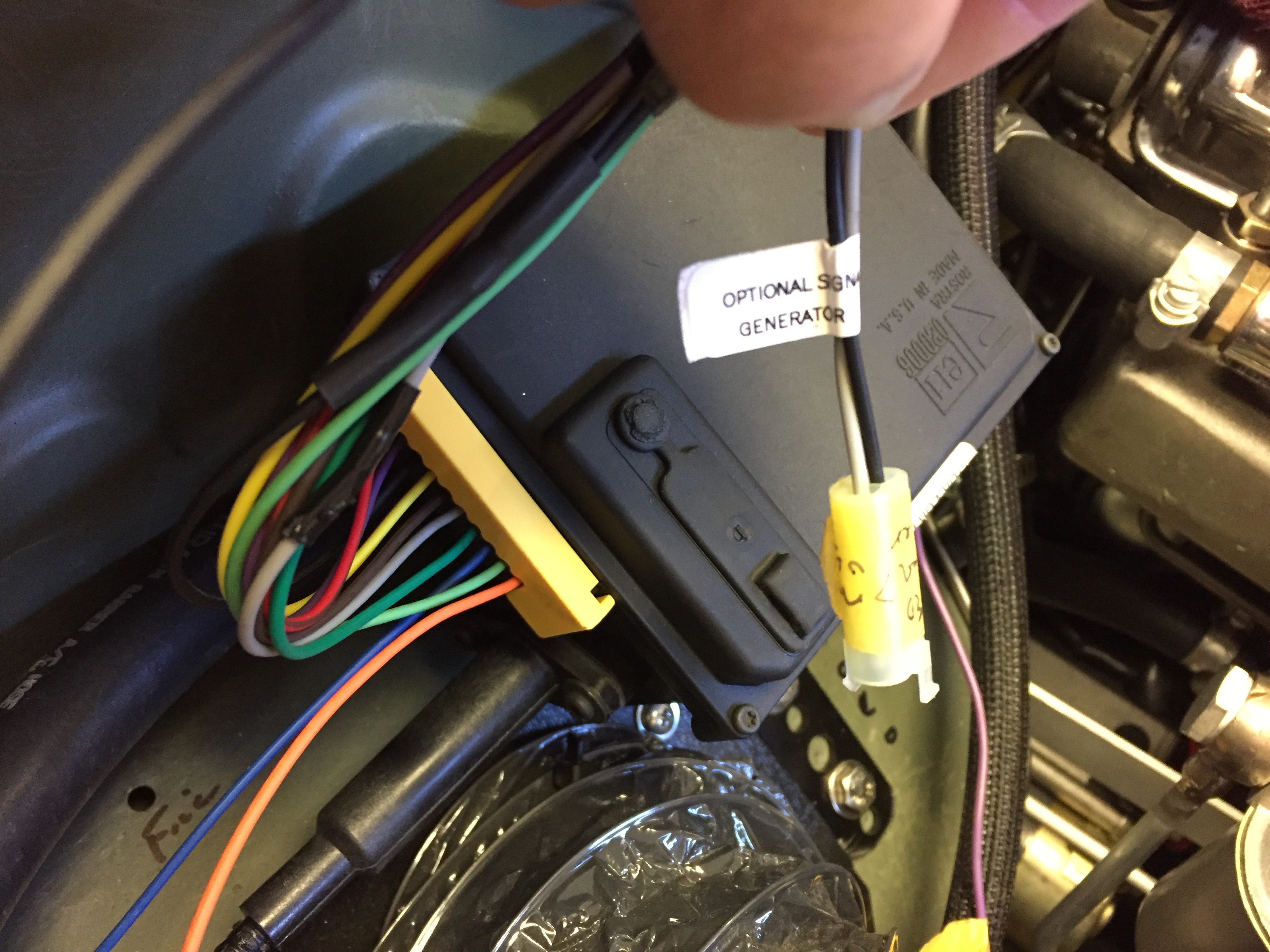
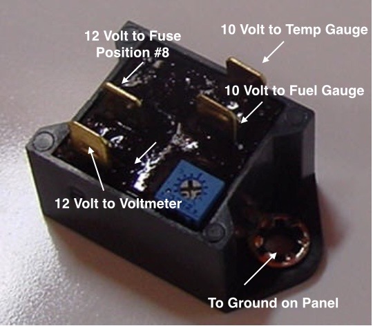
The orange wire from the motor is connected to ground. The black wire to the “inside” post (closest to the heater box) of the resistor. The slate wire from terminal #6 on the switch is connected to the “outside” post (closest to the blower fan) of the resistor. The white/green wire from terminal #8 on the switch connects to the “inside” post on the resistor. The green/yellow wire from the #4 terminal of the switch is connected to the fuse position #11 for power. With this wiring in place, the lower position of the switch is “off,” the middle position is “Low Speed” and the upper position is “High Speed.”
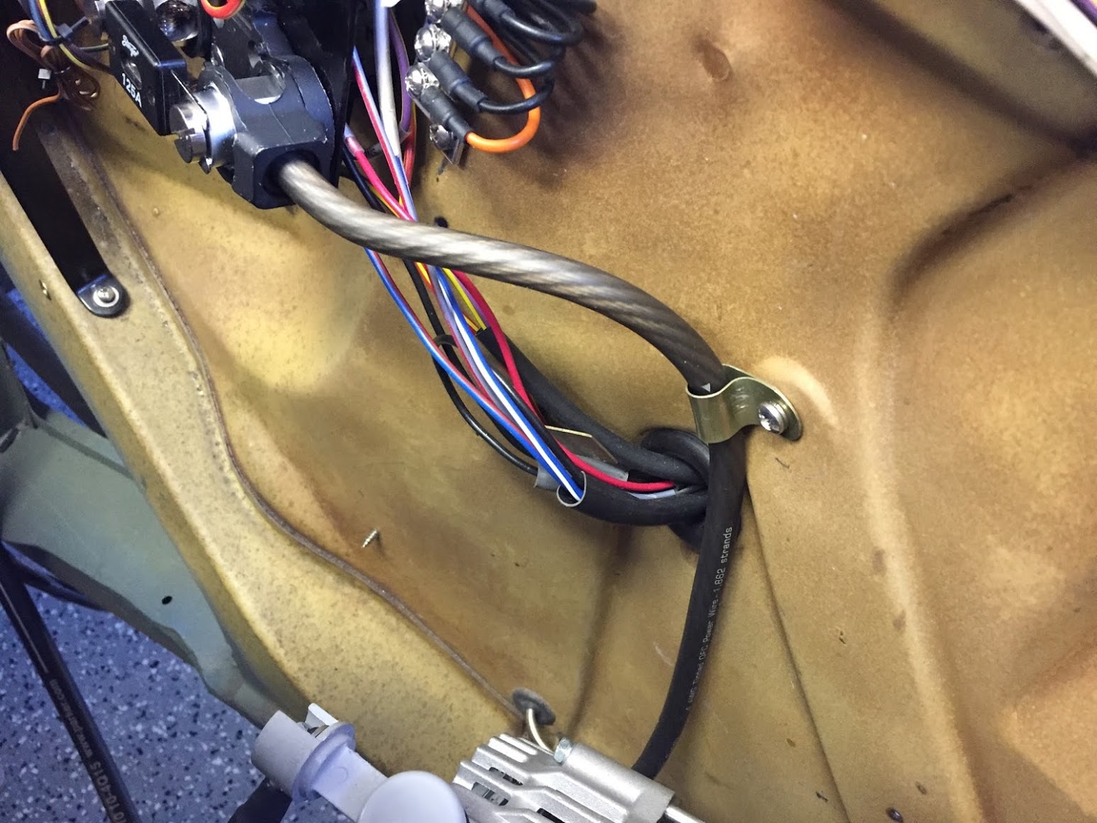
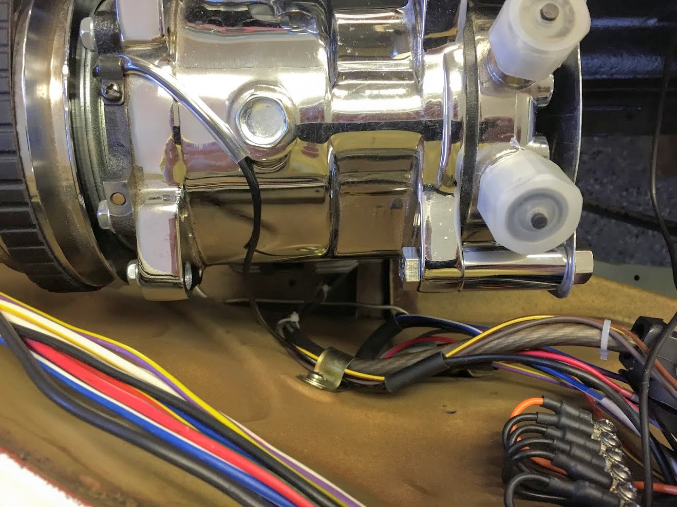
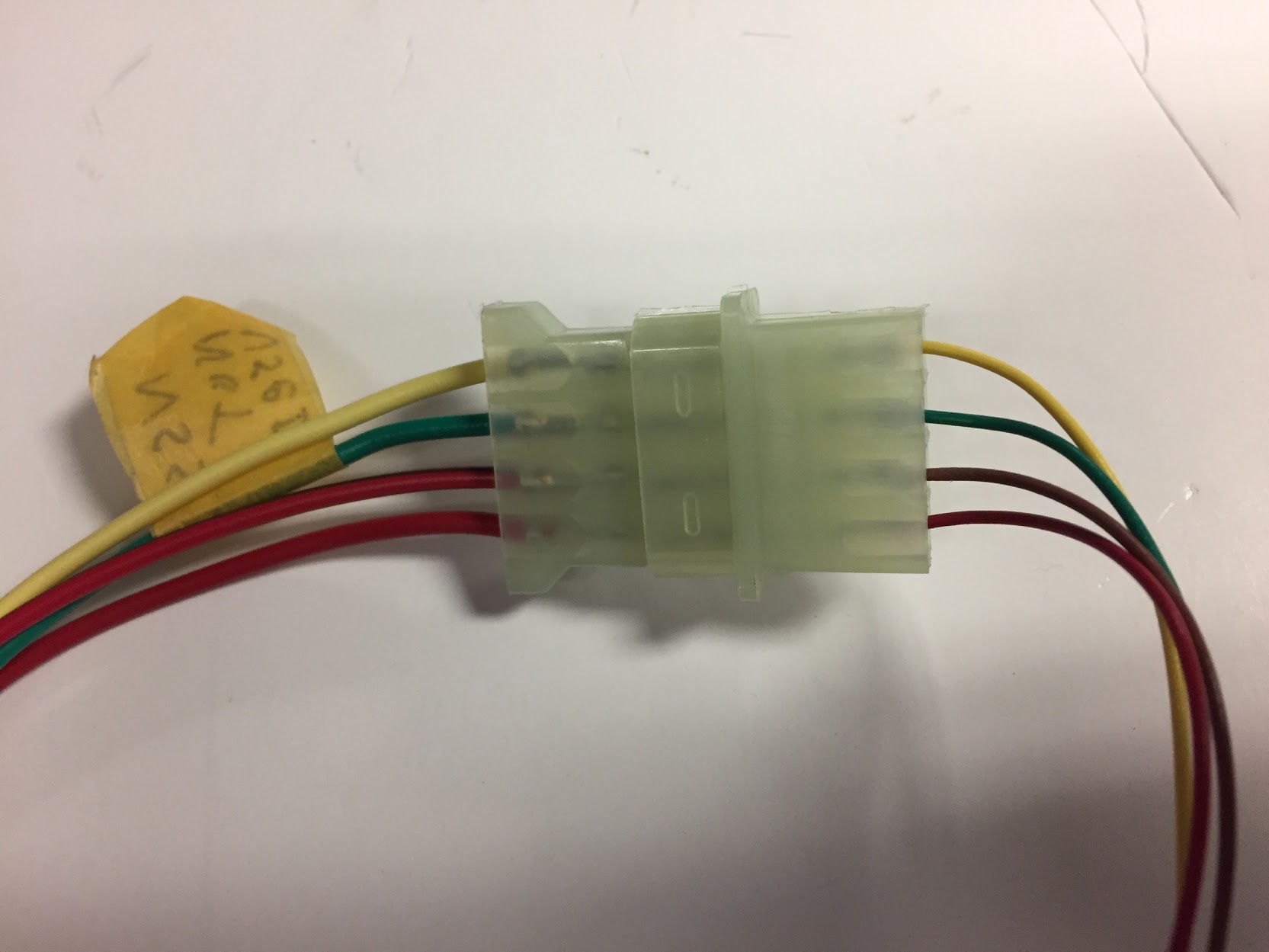
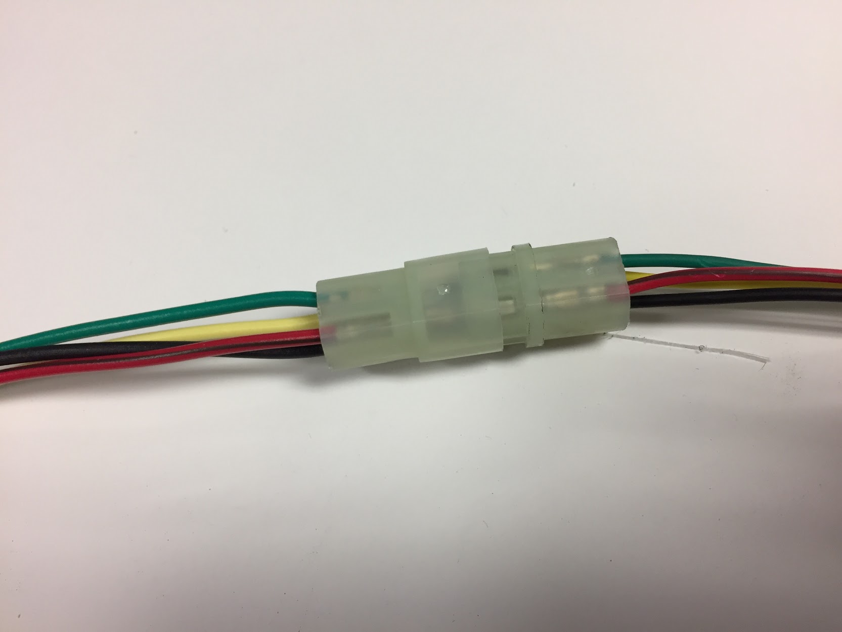
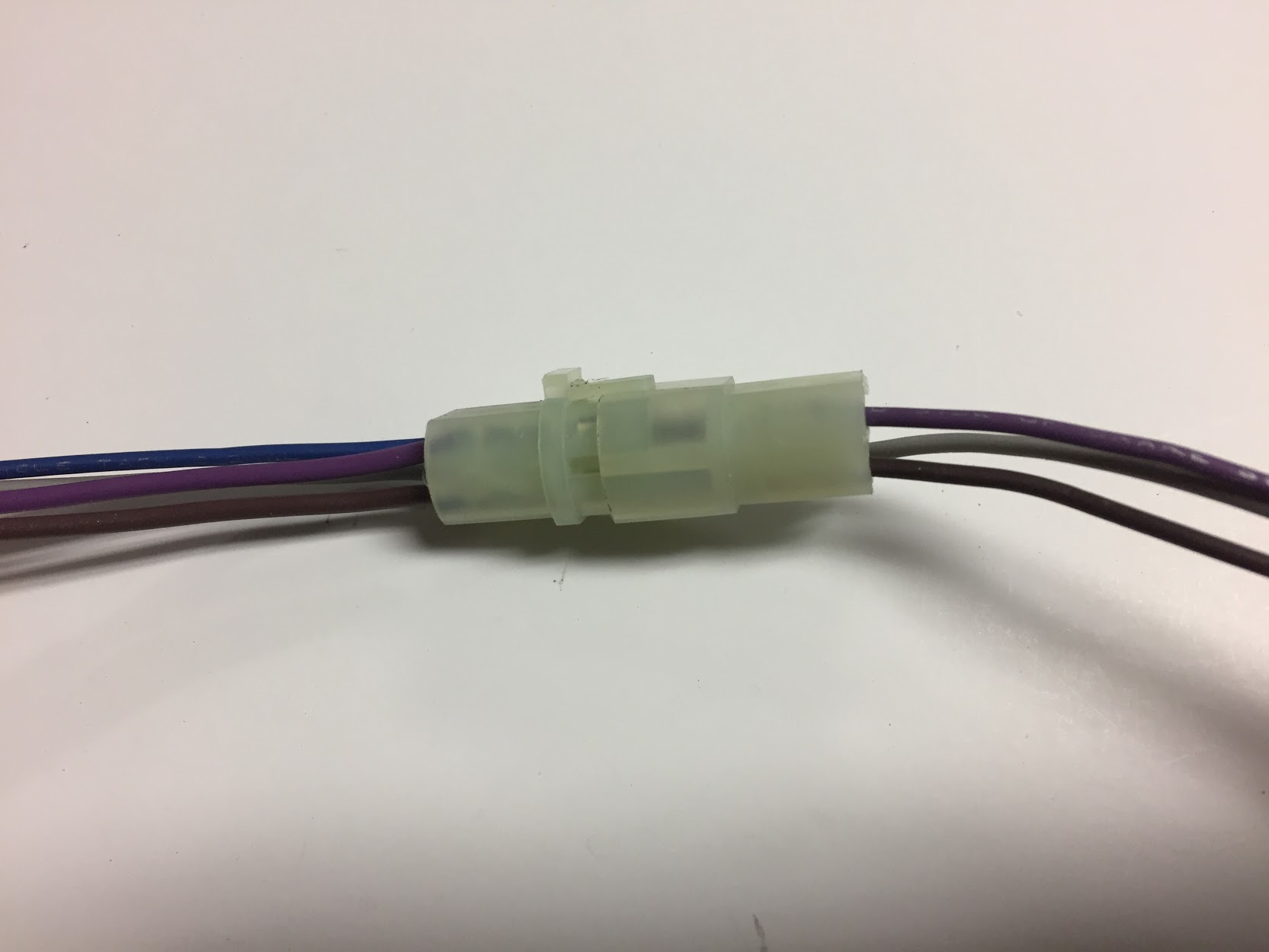
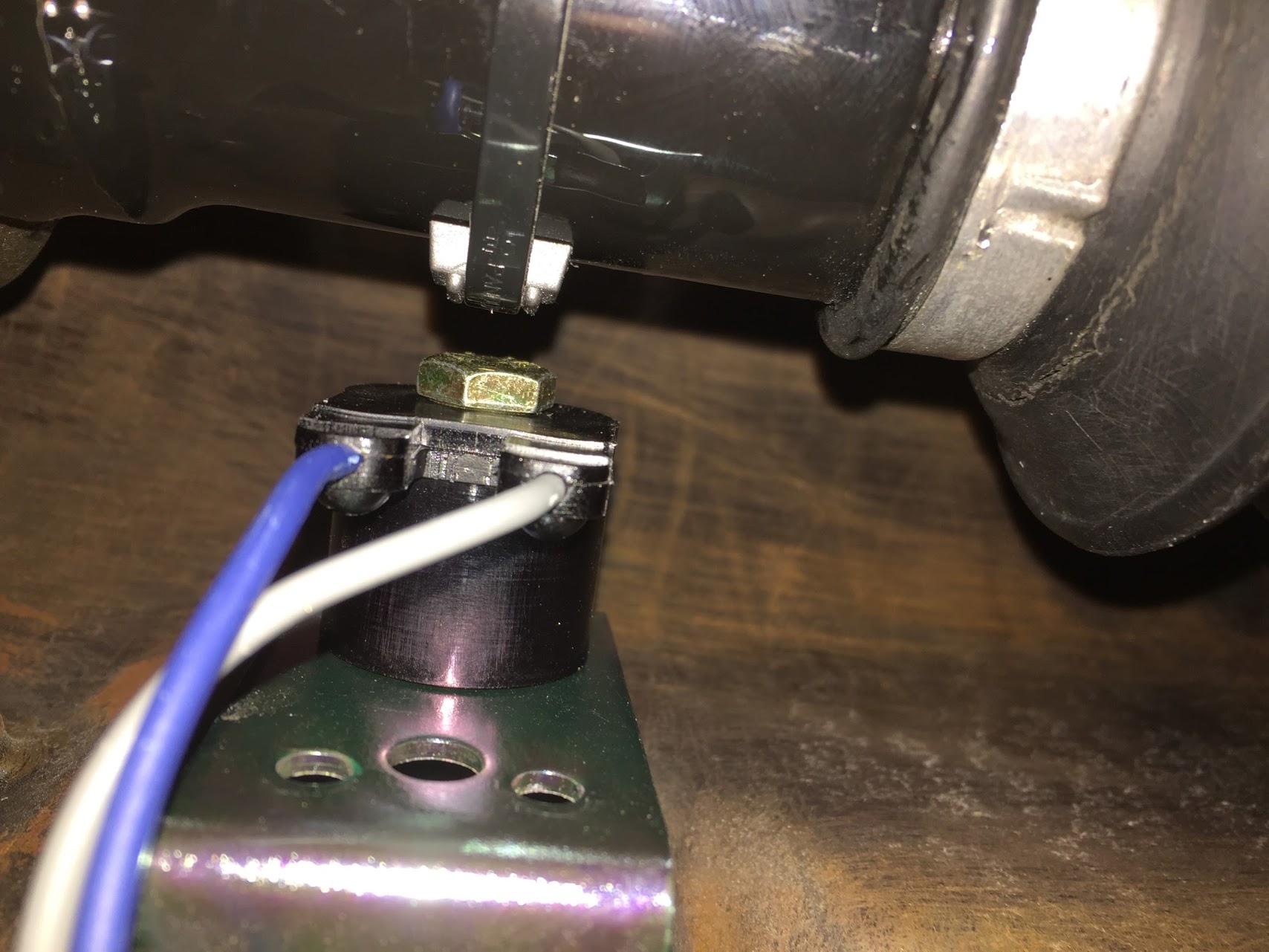
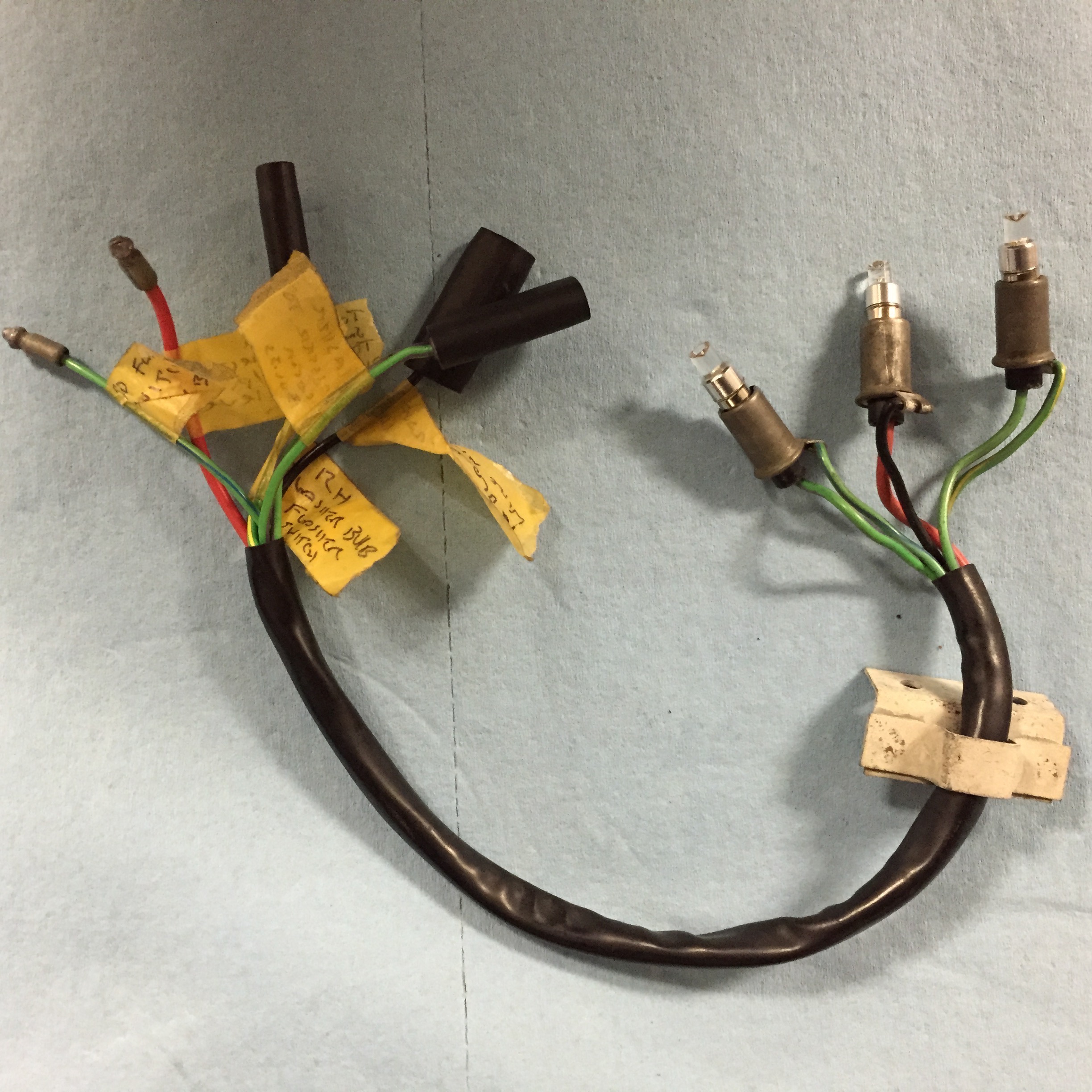
I created a pigtail (seen blow) from the resistor for the heater fan wiring. Two wires in the pigtail are connected through two-way snap connectors to wires of the same color which route through the firewall and ultimately back to the Fan Switch. The black wire goes directly to the fan motor.

Heater Fan Wiring
I contacted Clayton to determine the amperage draw for the upgraded motor and received this response from Phil Beveridge:
Dear Mr.Rose,
At 13.5 volts, running at full speed, the motor will be drawing 10.8amps.
Kind regards,
Phil Beveridge.
Per the Clayton instructions, I used silicone to seal the inner flap in the closed position.
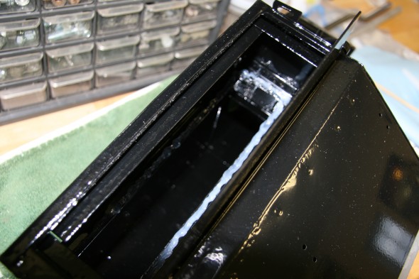
Silicone Sealed Flap Shut
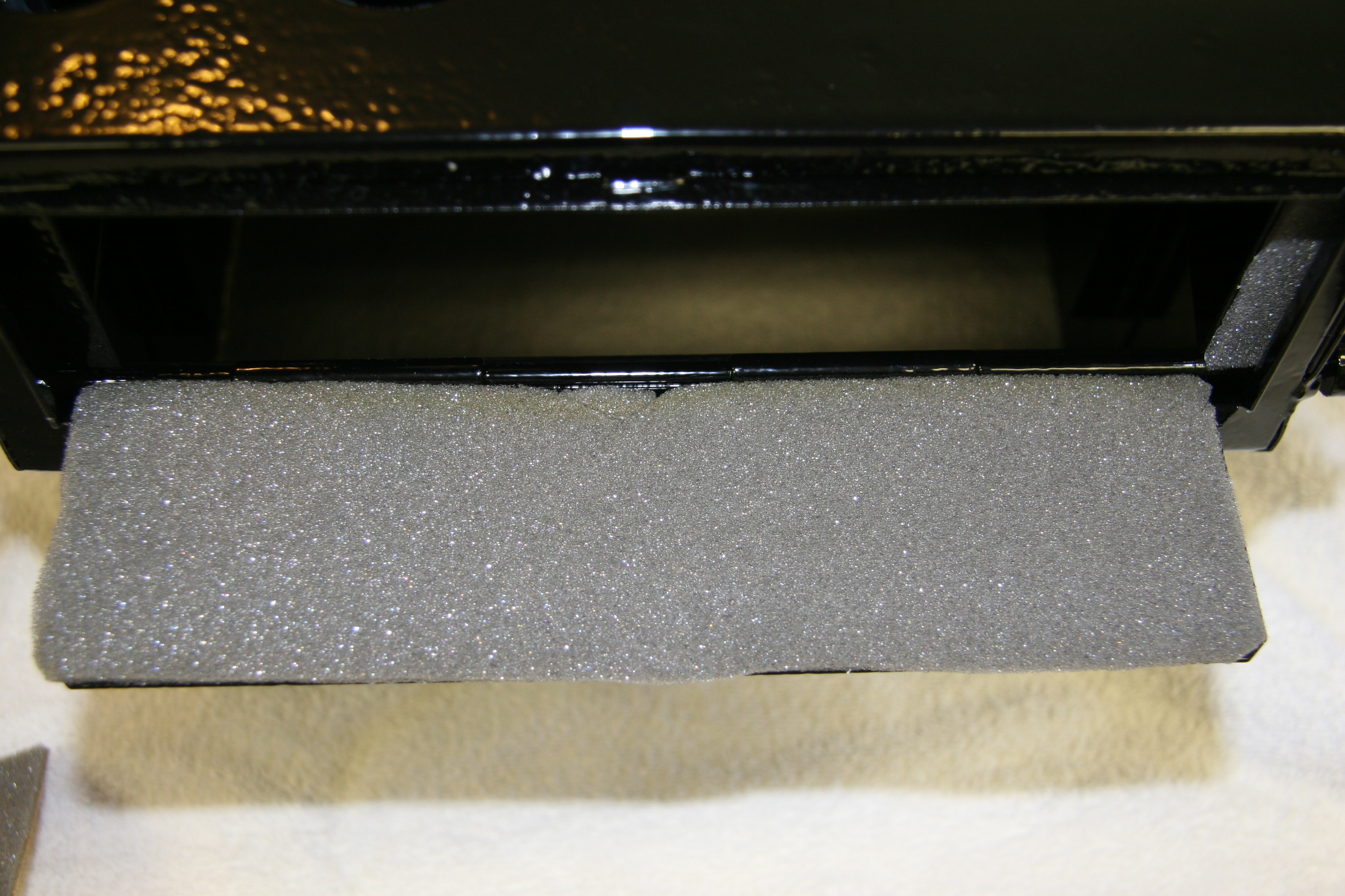
And, added foam to the inside of the bottom flap:
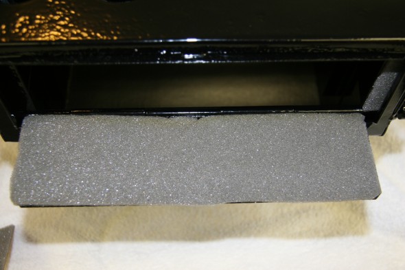
Foam Padding on Flap
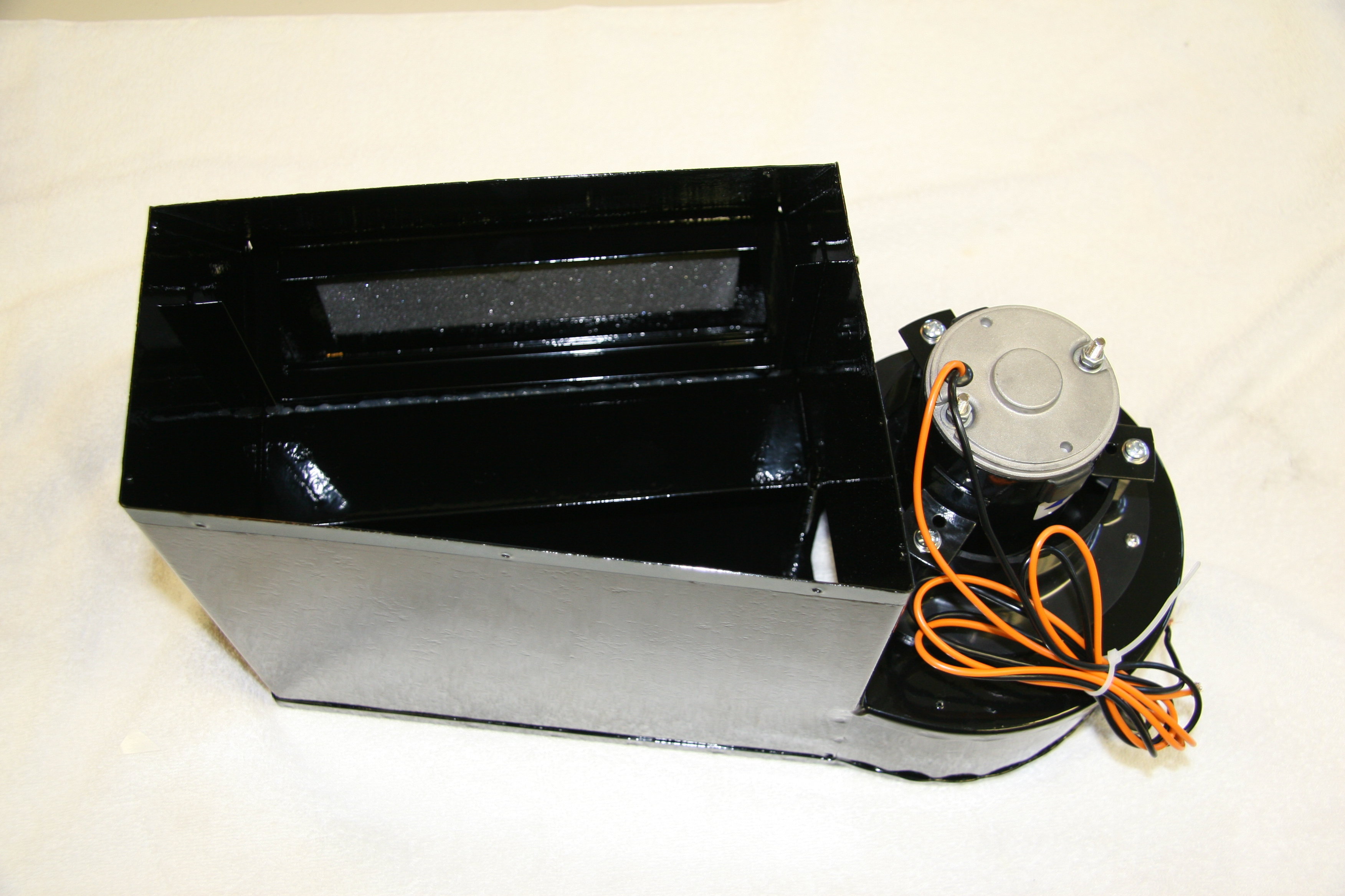
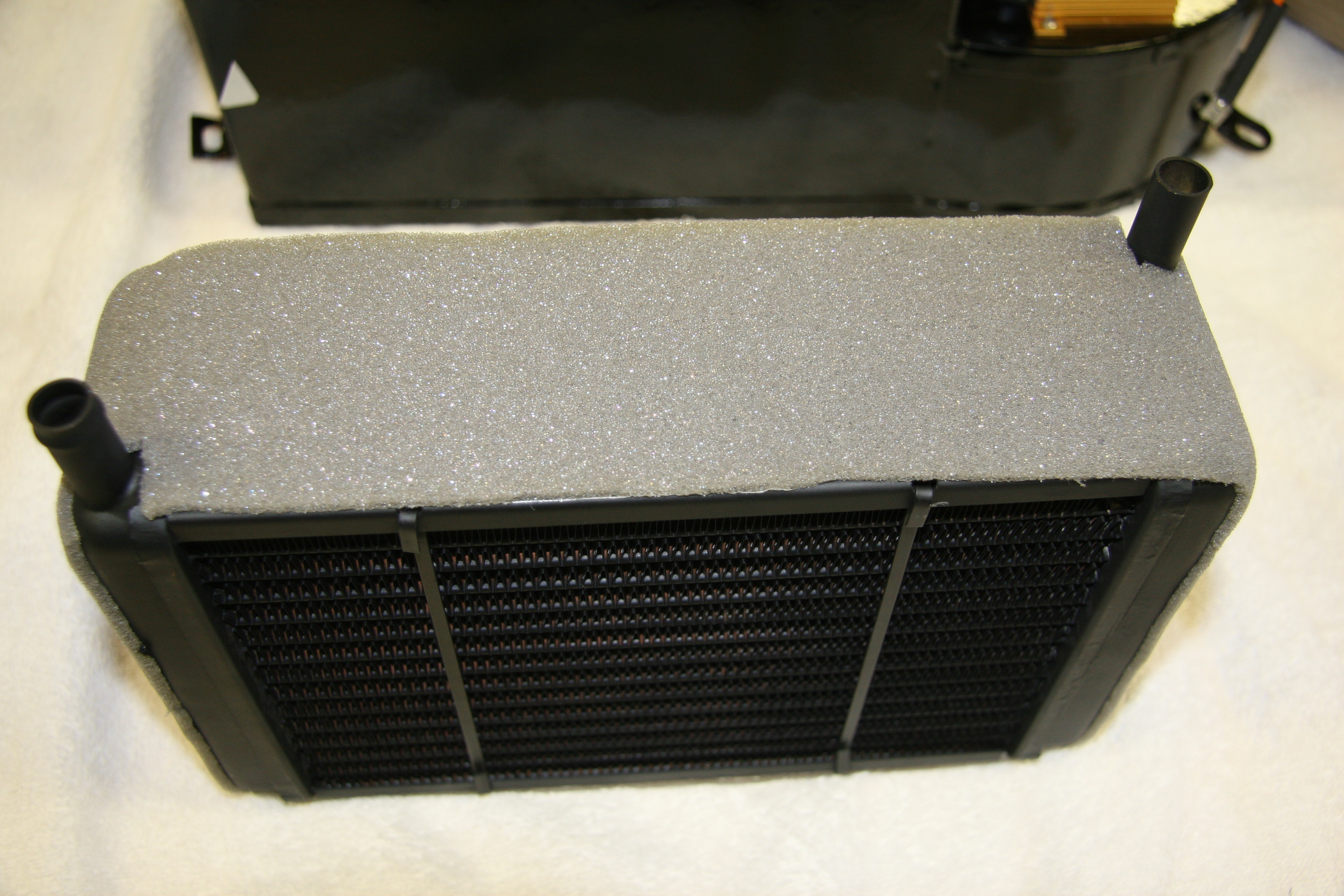
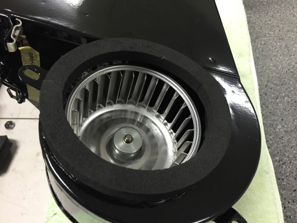
I then installed the motor and the heater matrix after wrapping it with foam:

Renewed Heater Box
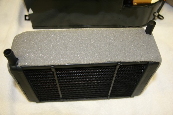
Clayton Heater Matrix with Padding
The next step was to install the heater box front lid:

Heater Box Lid Installed
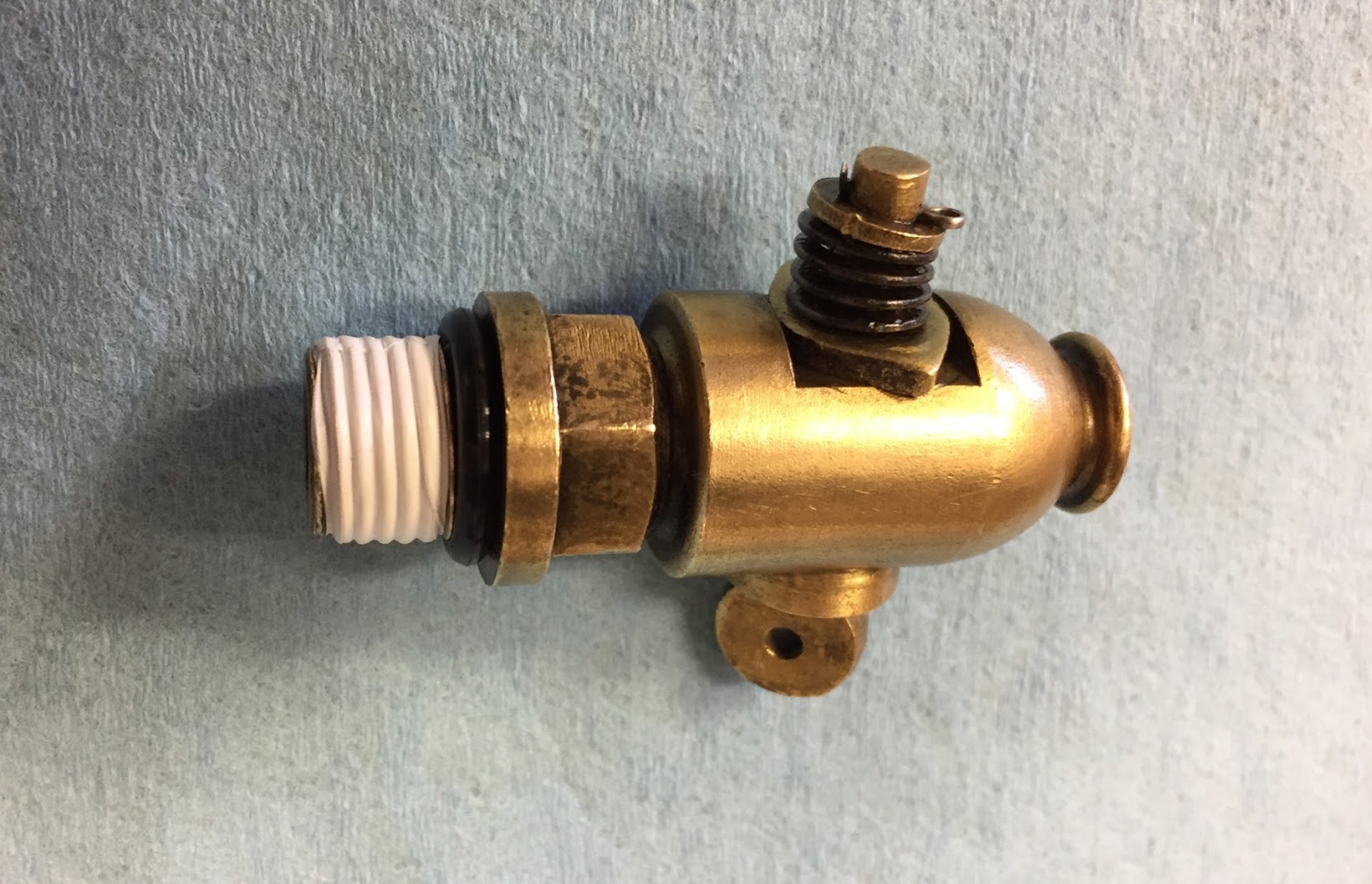
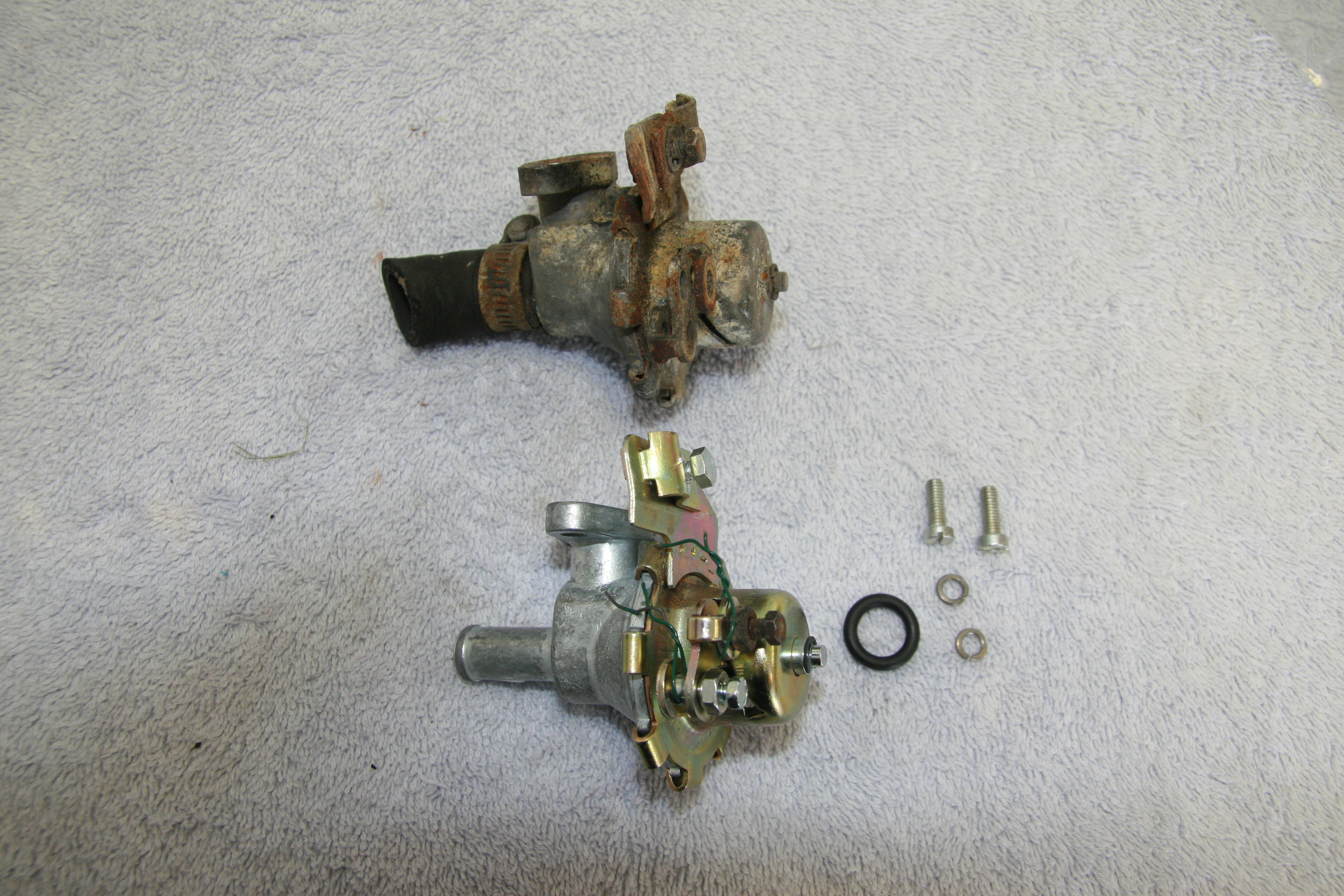
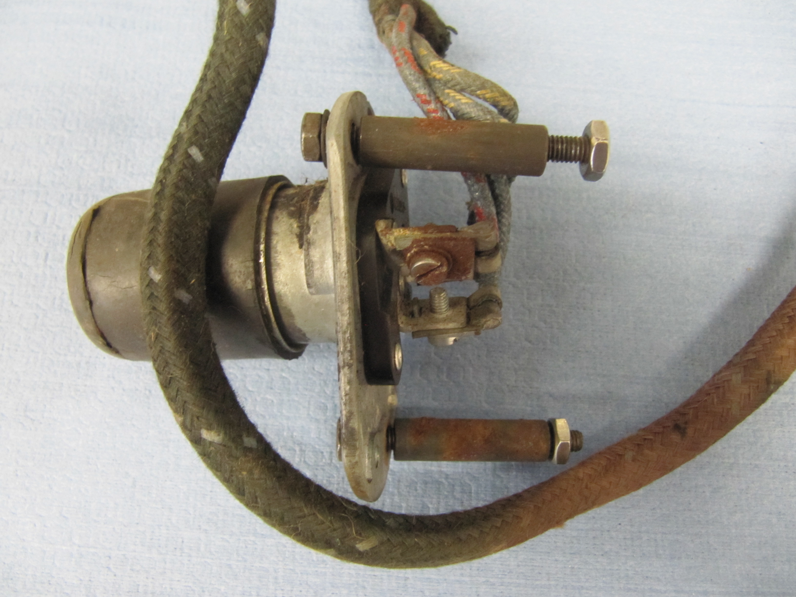
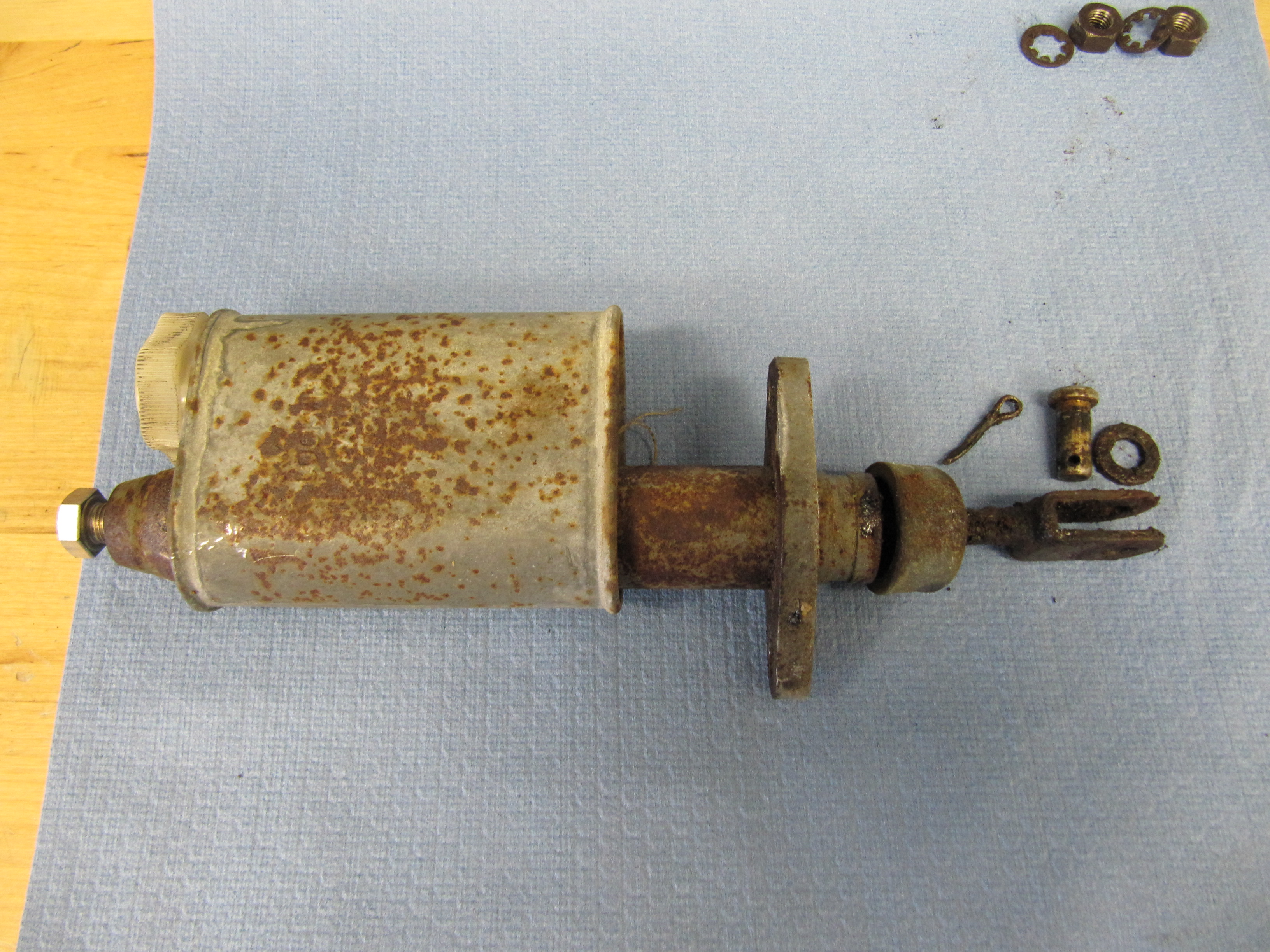
Water Valve
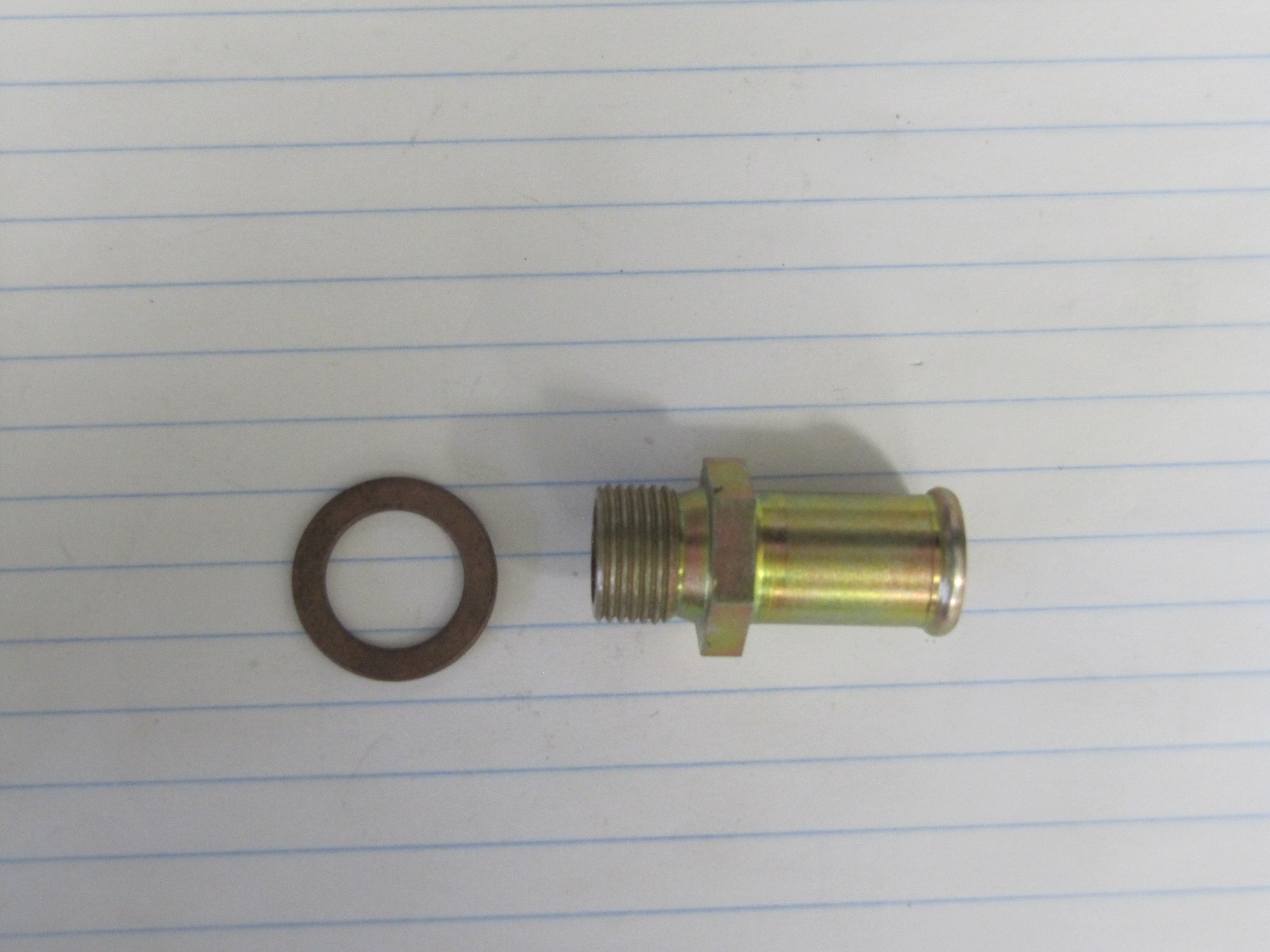
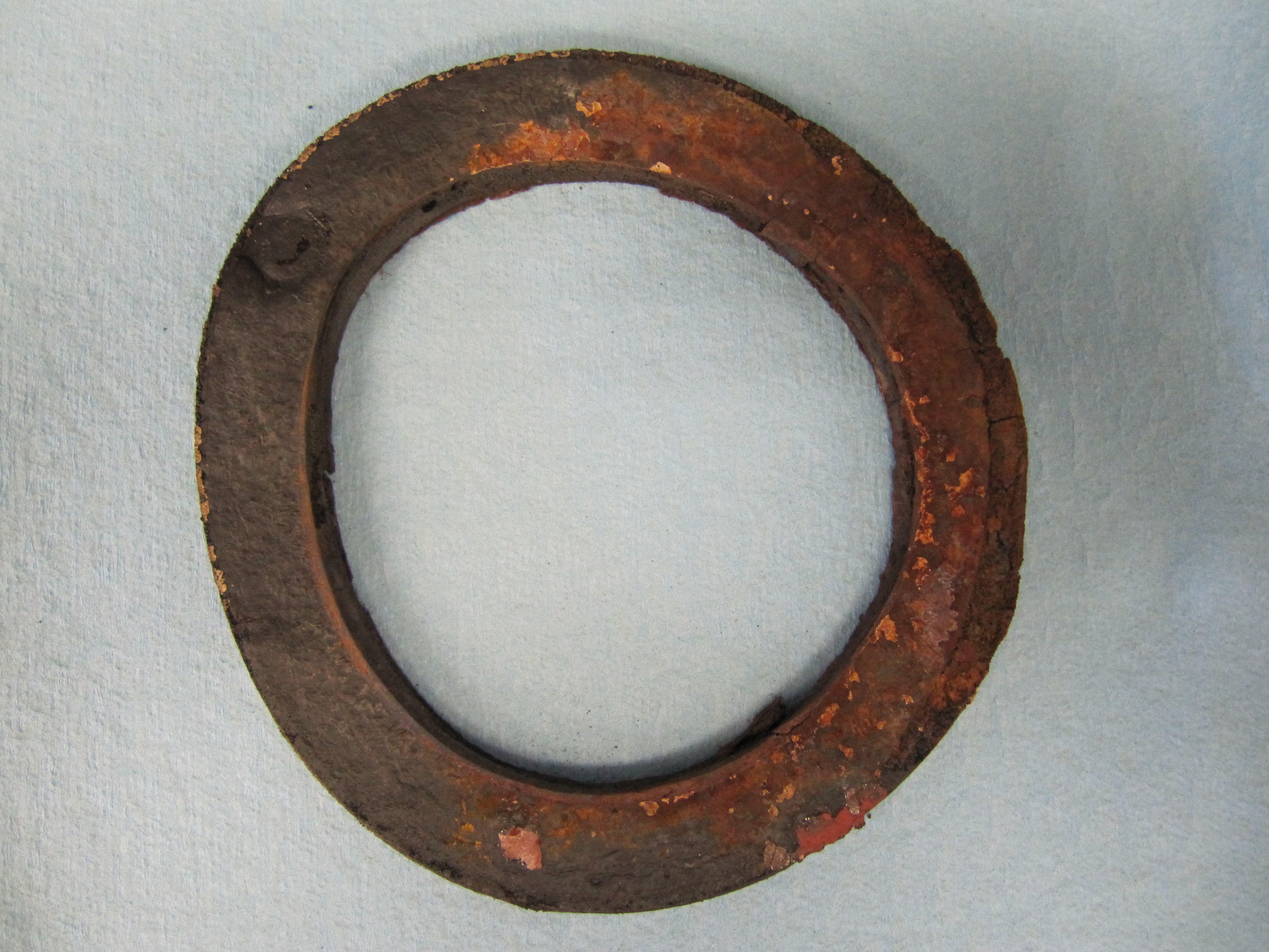
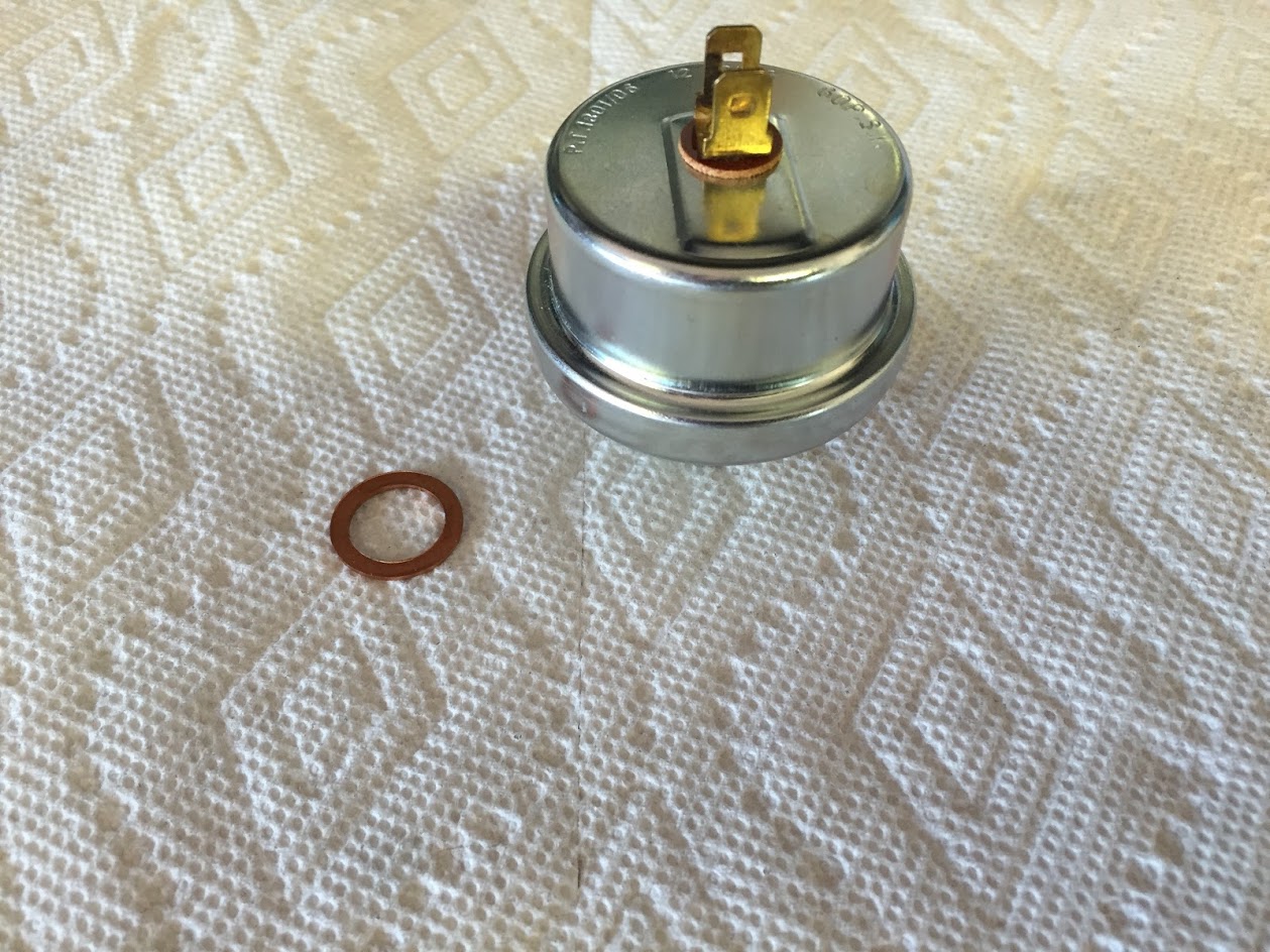
I ordered and installed a new water valve and rubber “O” ring seal.
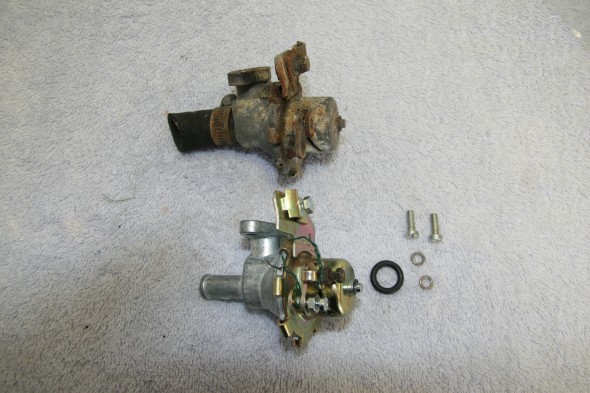
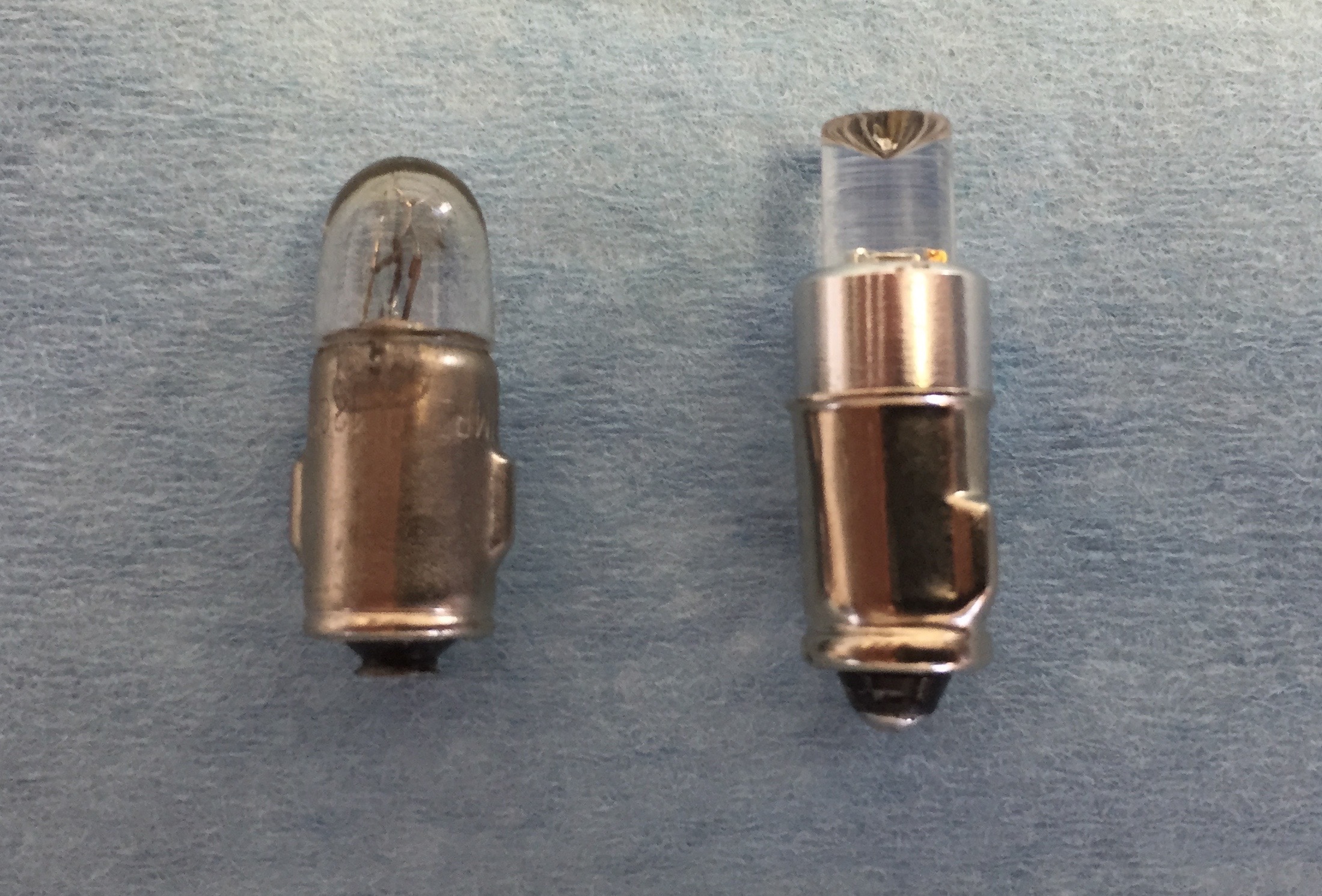
Original and New
“O” Ring Seal
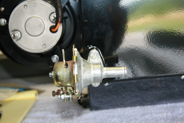
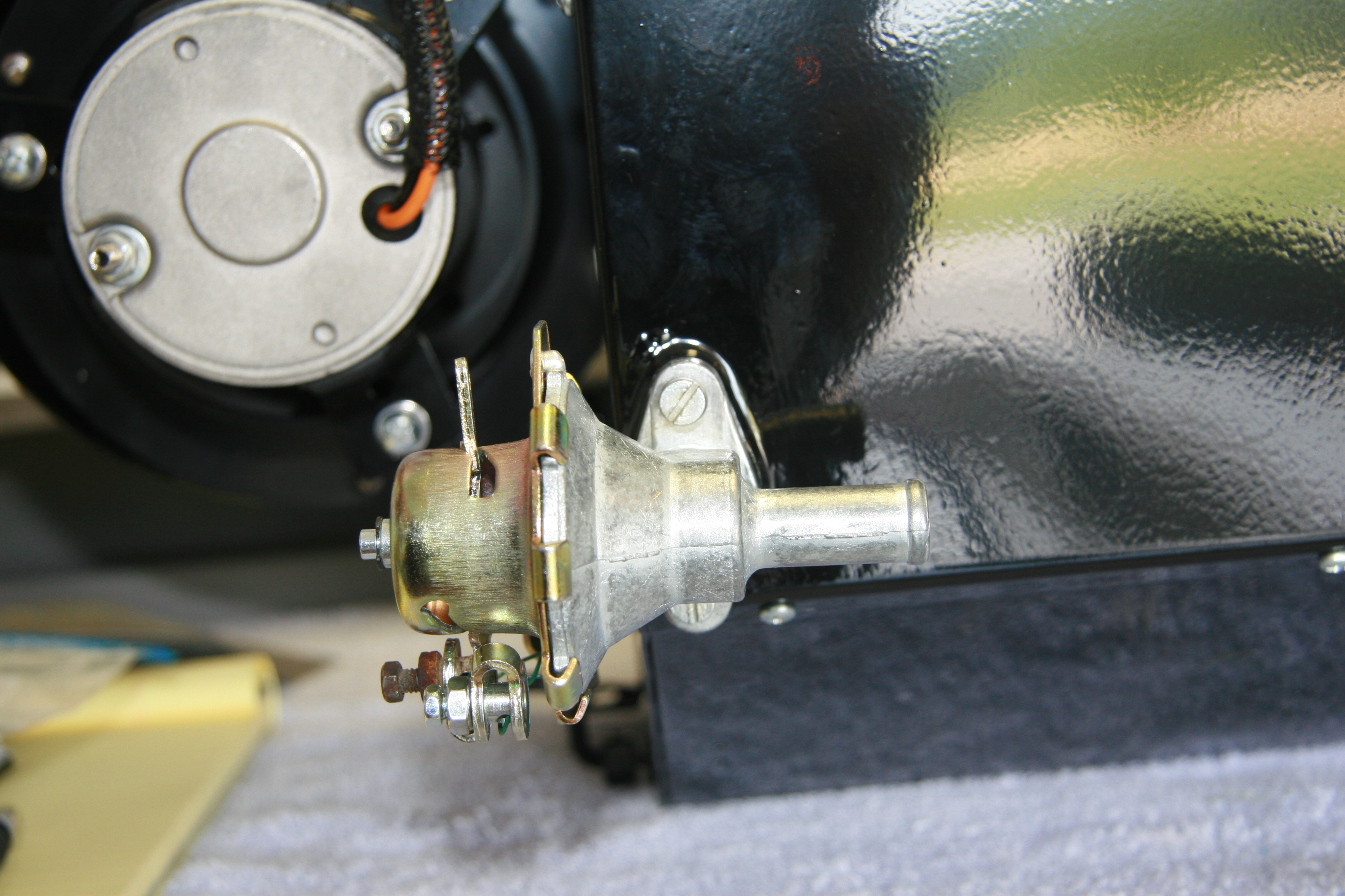
Valve Installed
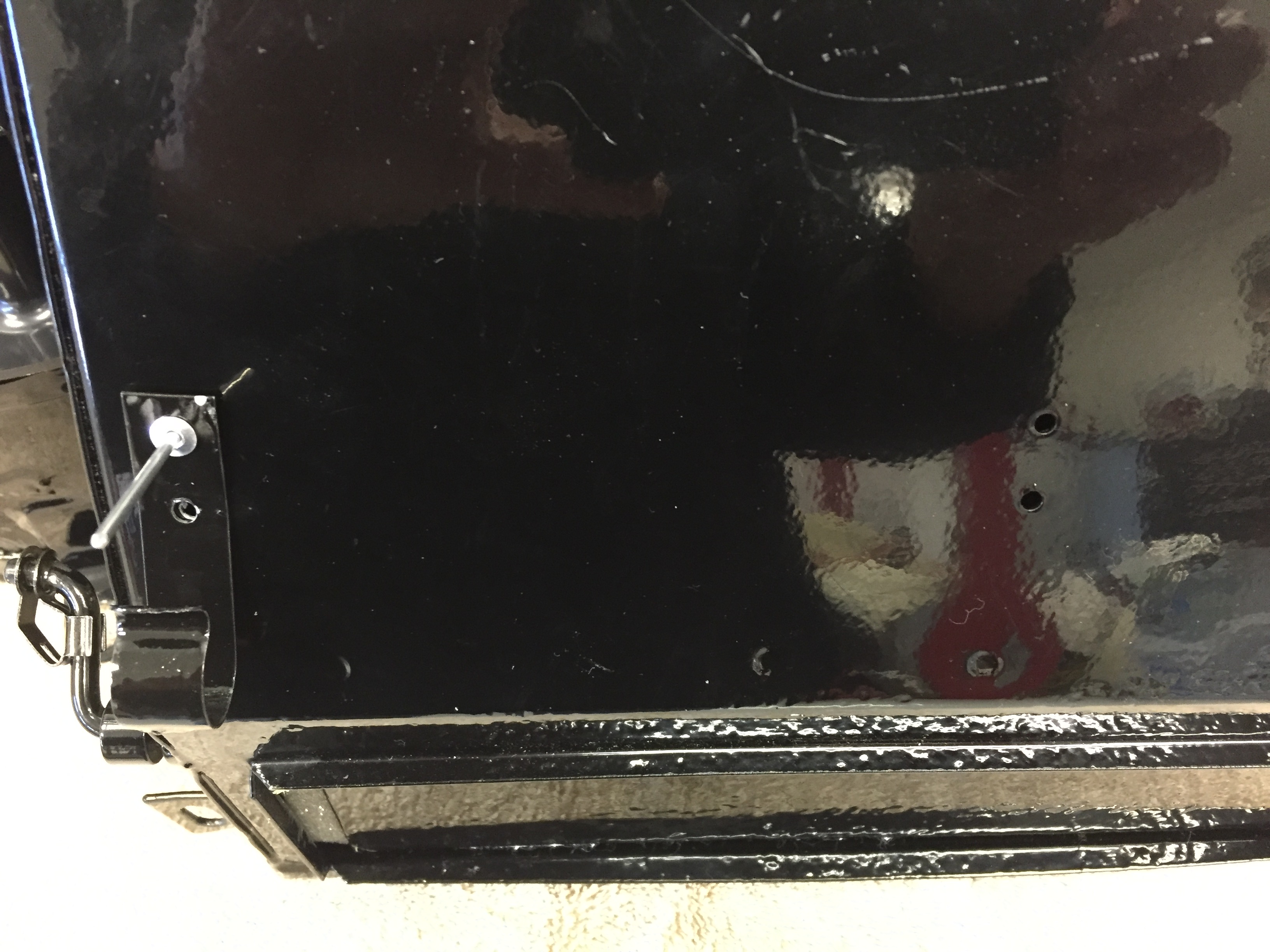
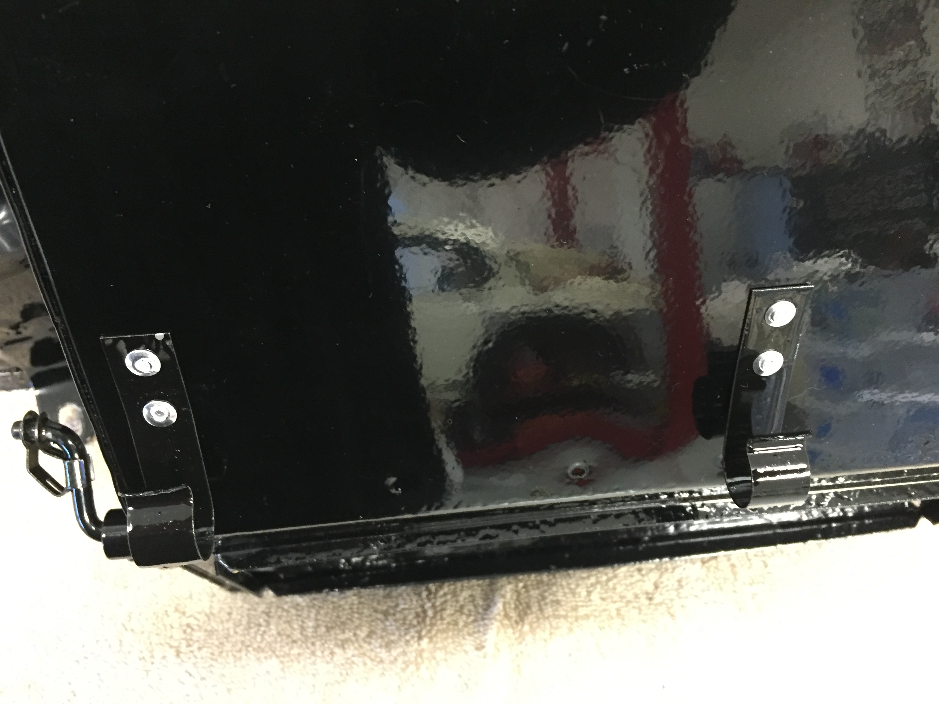
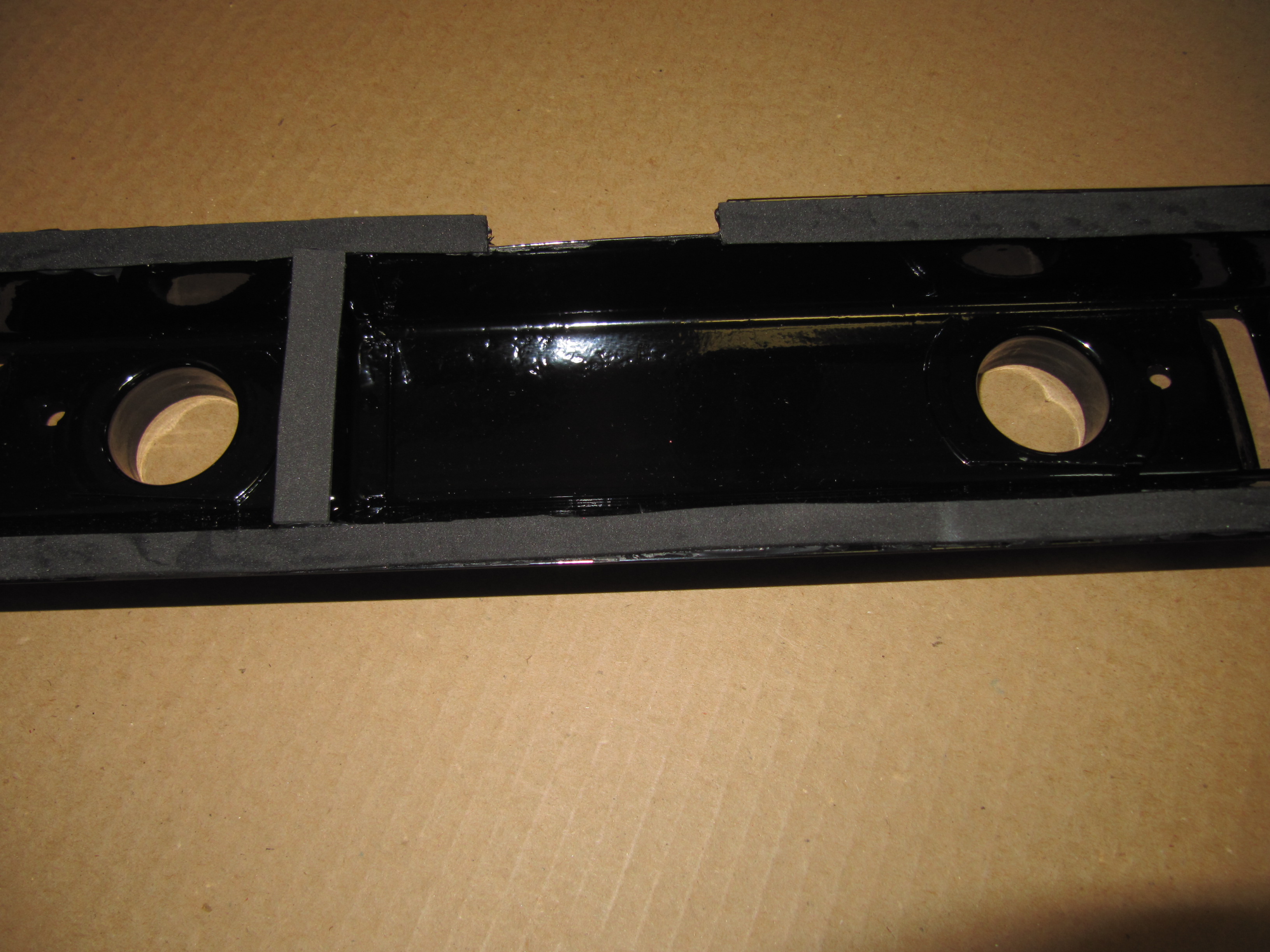
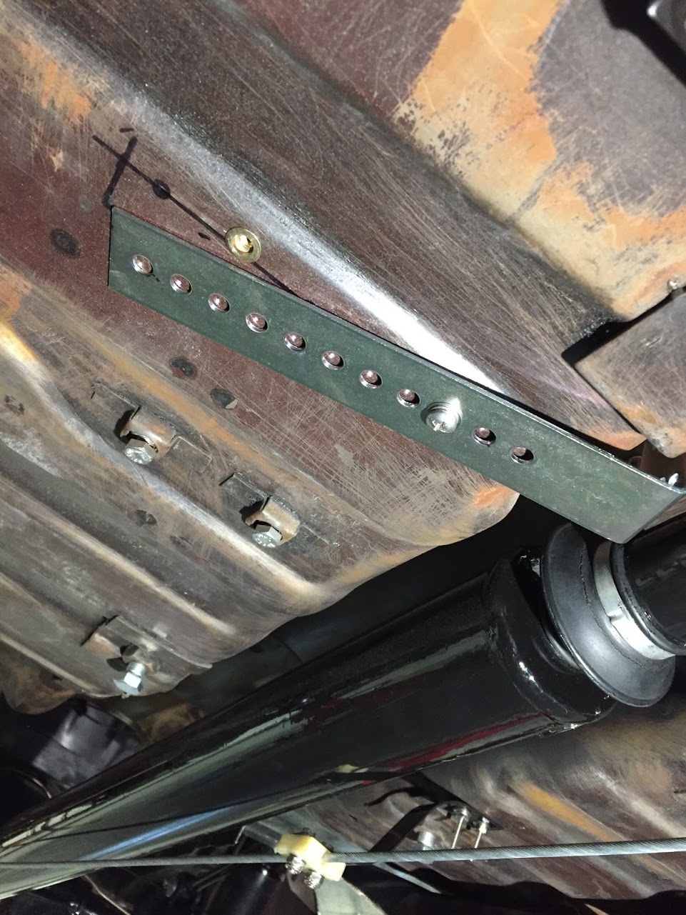
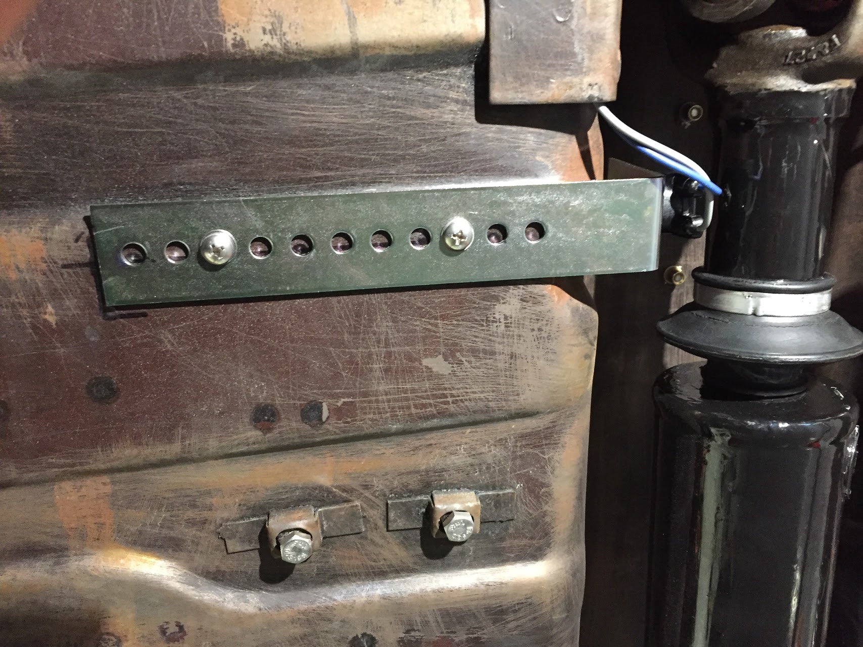
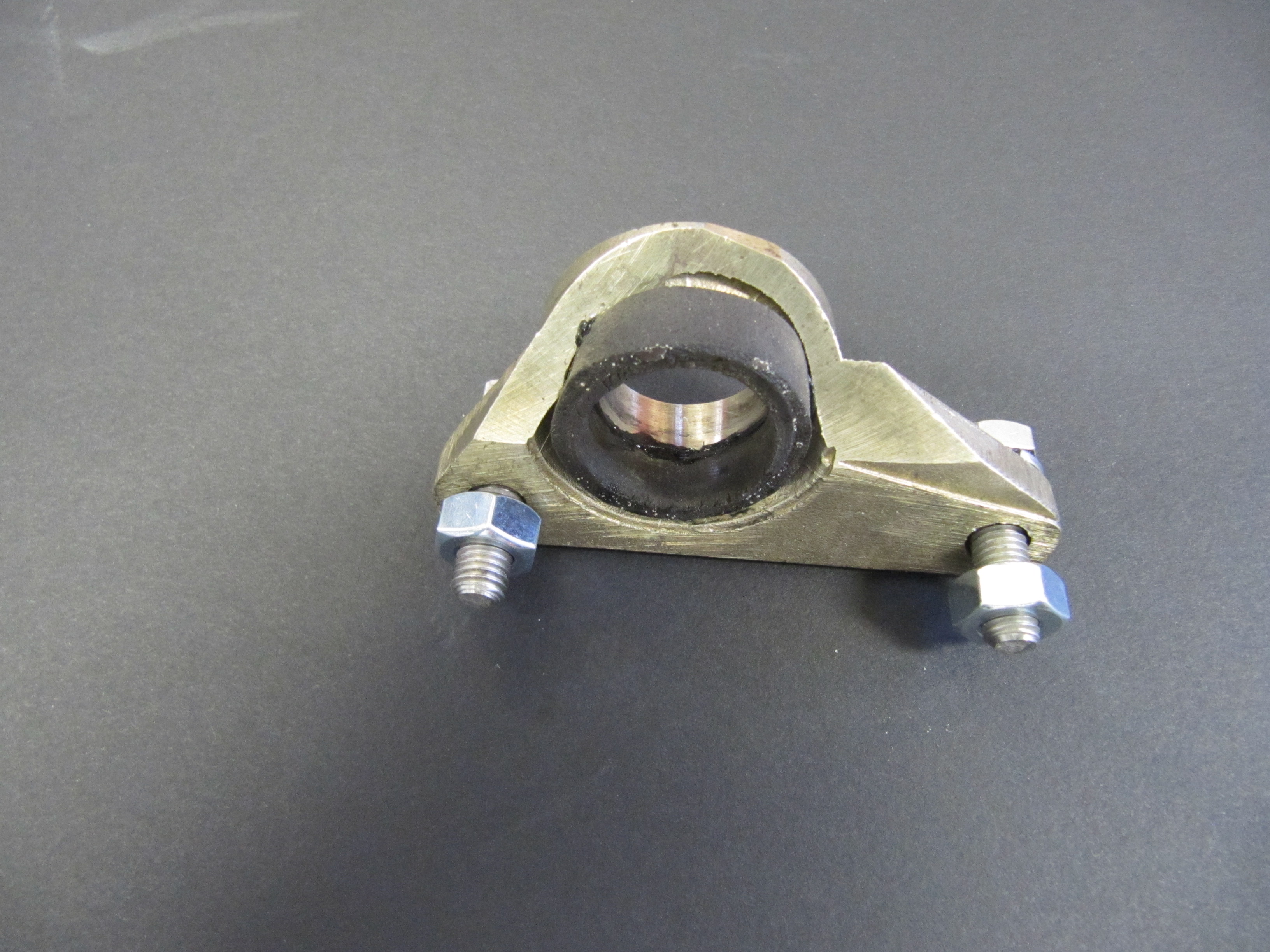
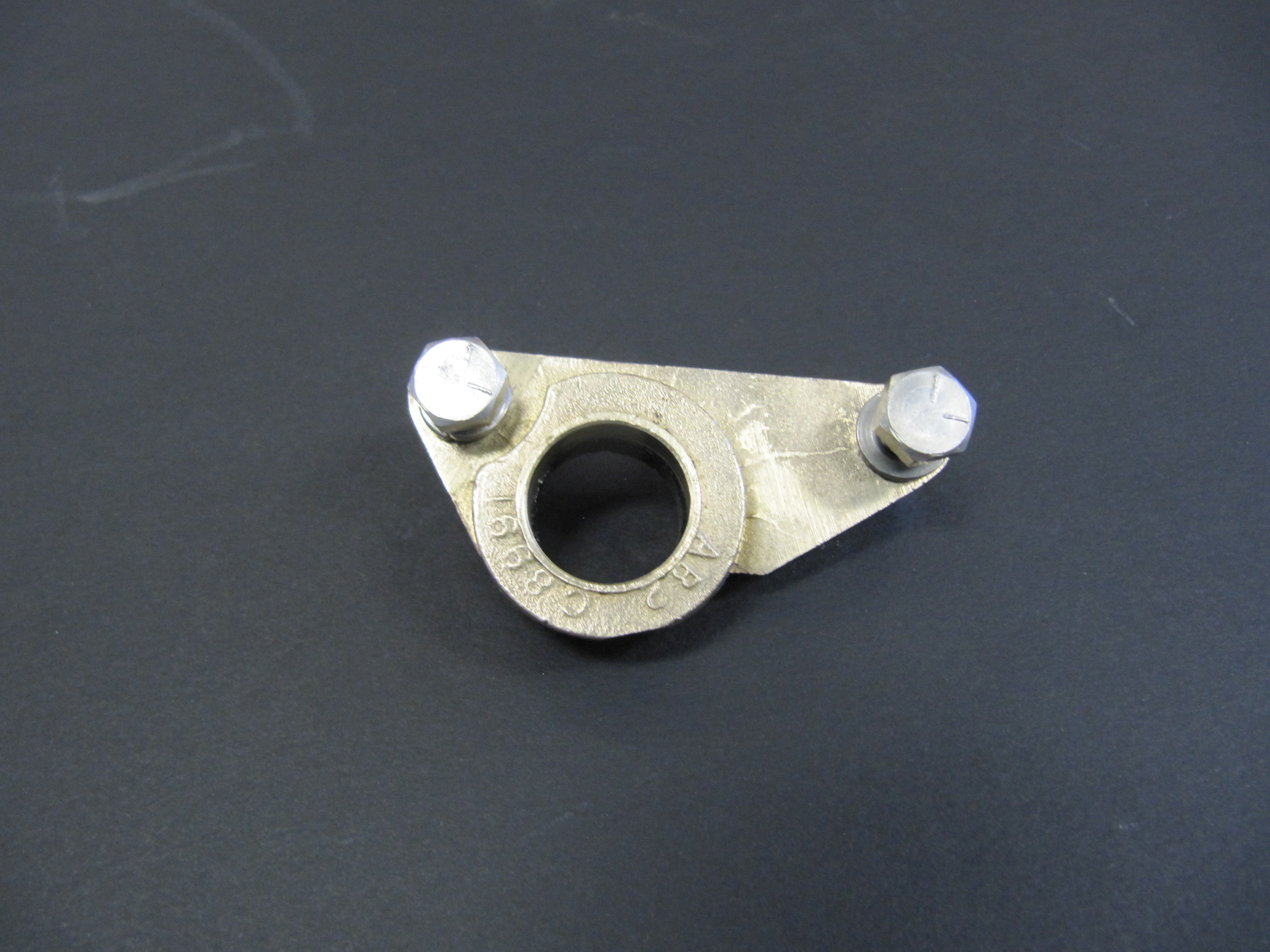
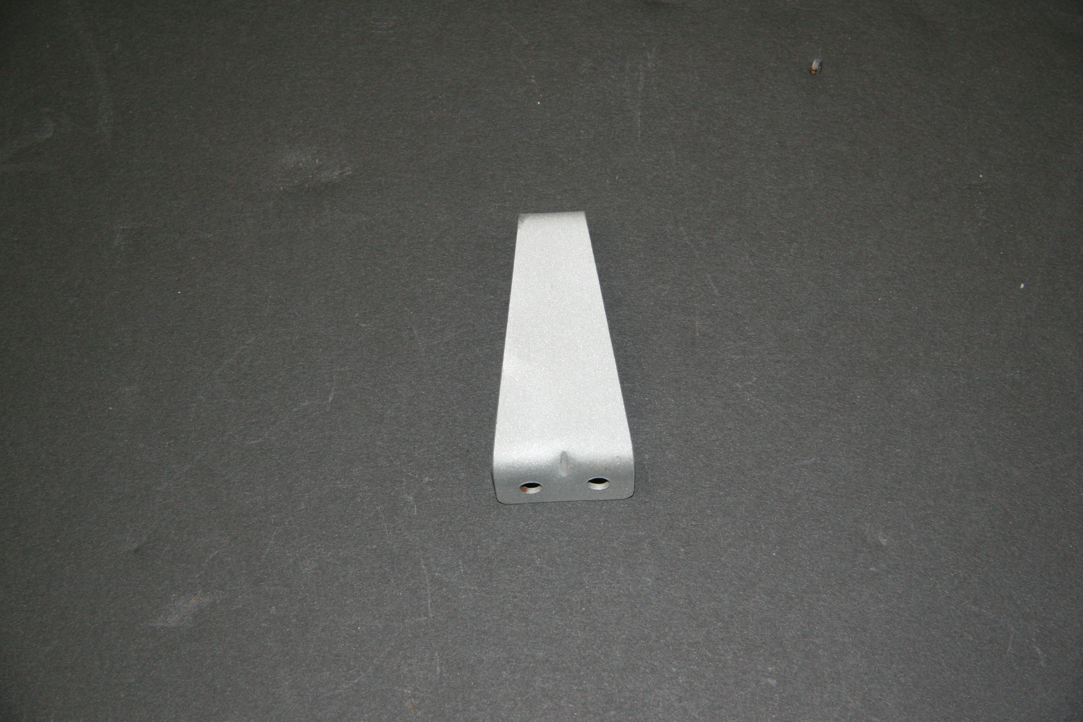
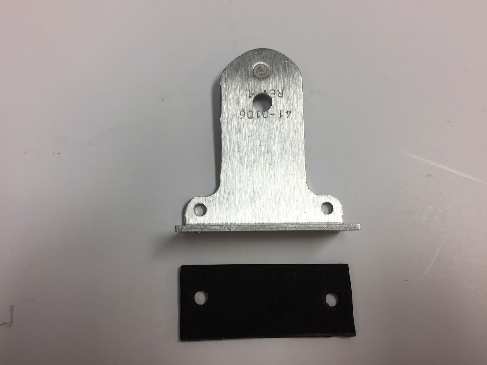
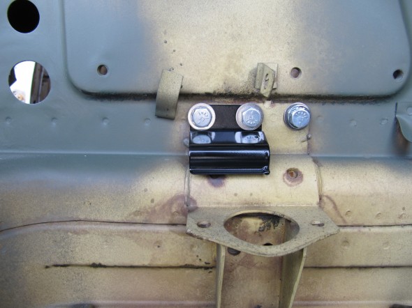
Heater Pipe Mounting Clips
Two spring clips are pop riveted (1/8″) to the angled face of the heater box. These are used to secure one of the water circulation pipes to the box. The Clips were originally painted black so they were media blasted and then painted with POR 15.

Holes in Heater Box for Pipe Clips
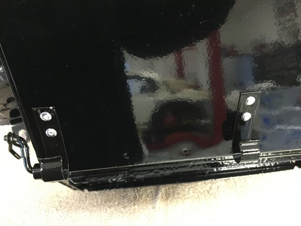
Heater Pipe Clips Riveted to Heater Box
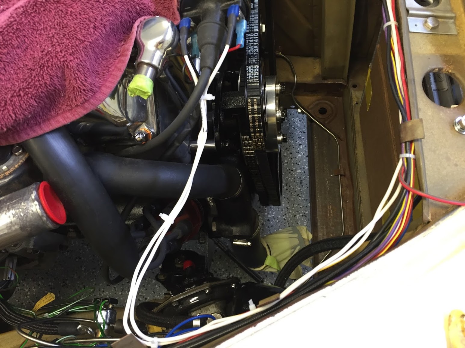
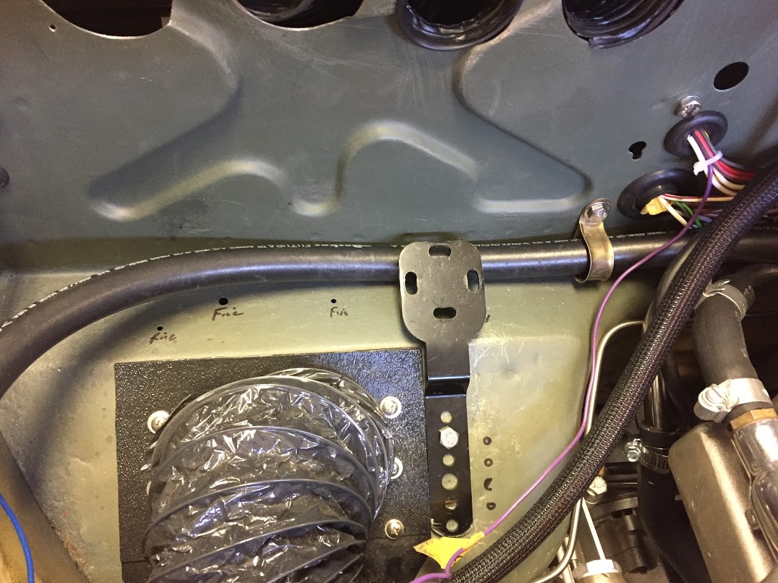
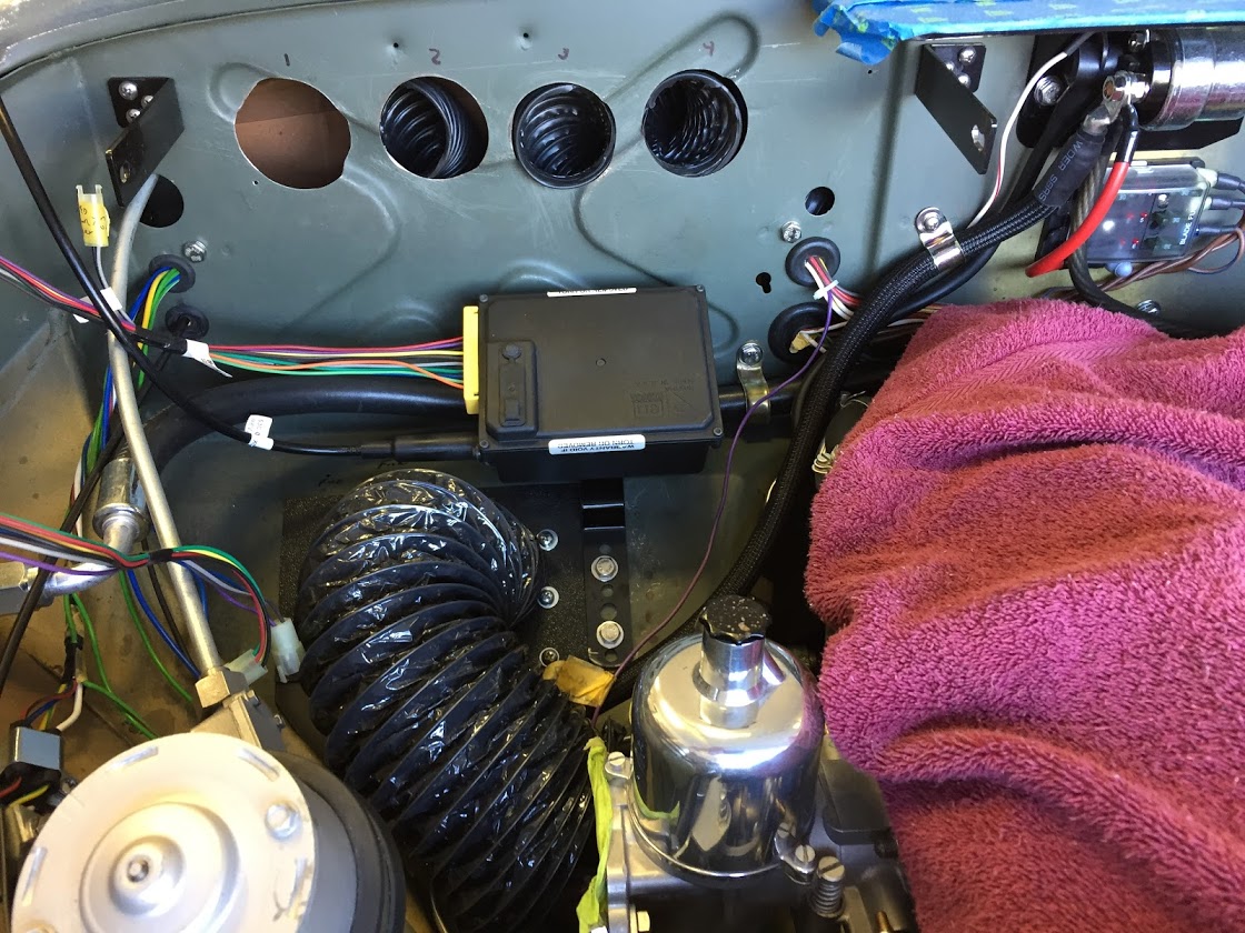
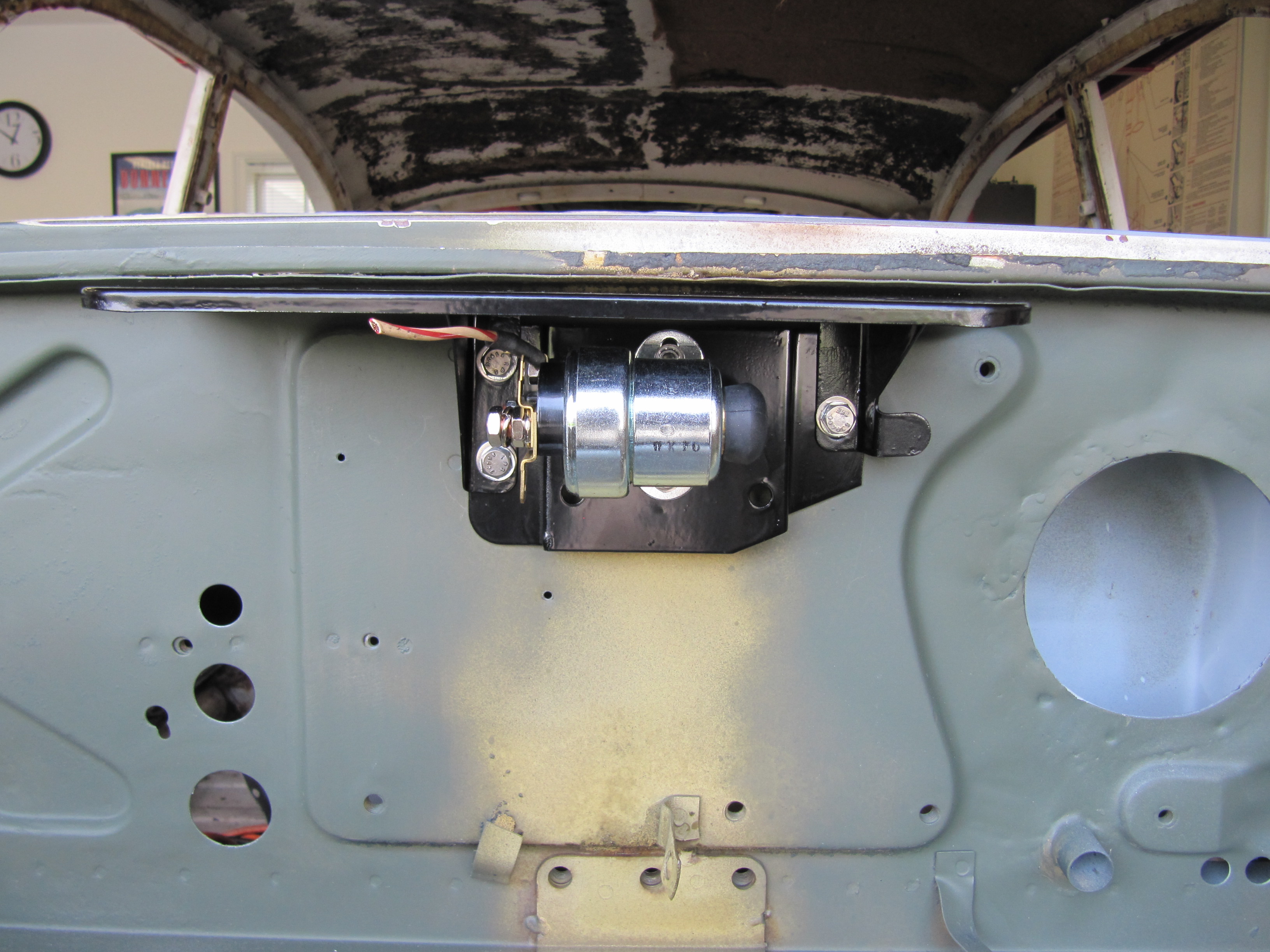
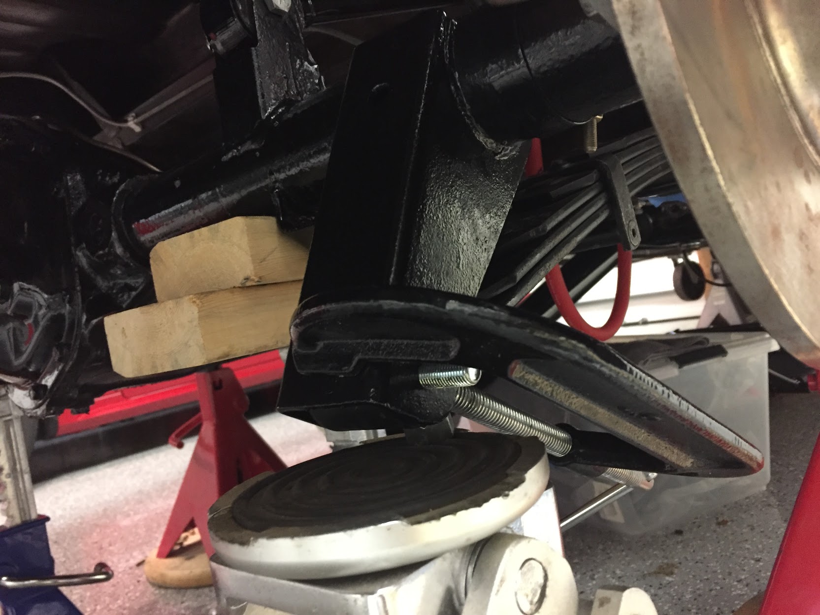
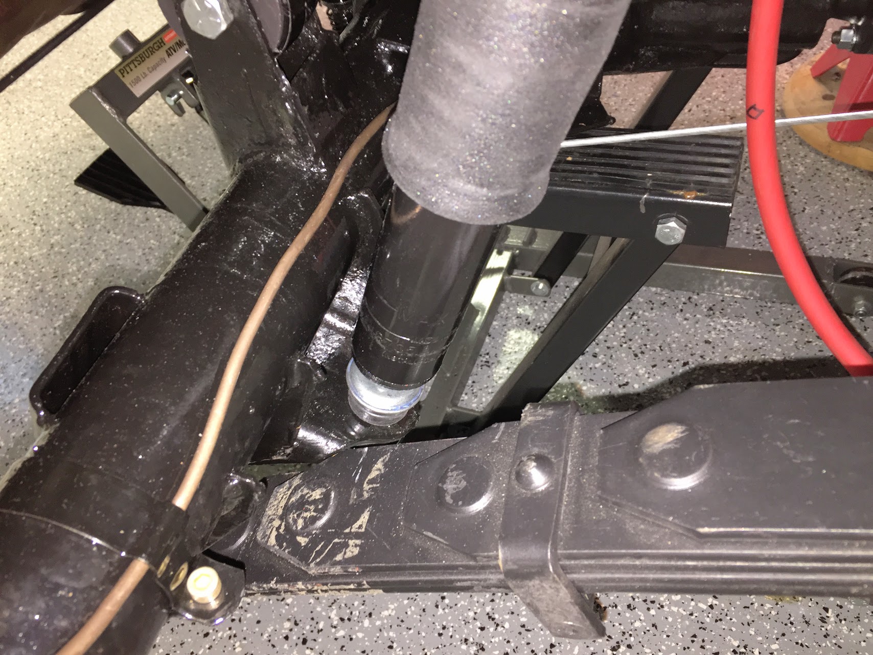
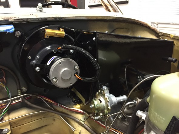
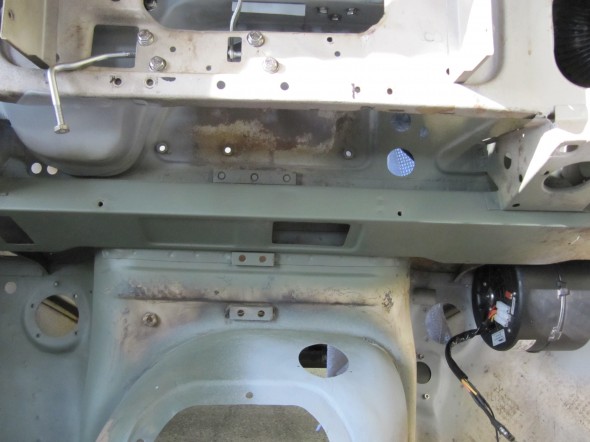
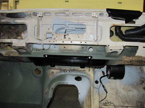
Trial Fitting of the Heater Box
I need to install the heater box for completion of the wiring harness and to see how the box would fit with other “non-original” items in the engine bay. I was particularly curious about any conflicts that might arise from the addition of the power steering pump.
There are several foam insulation seals that need to be installed between the scuttle, firewall and base of the heater. These were sourced from Clayton, XK’s Unlimited and McMaster Carr and installed temporarily.
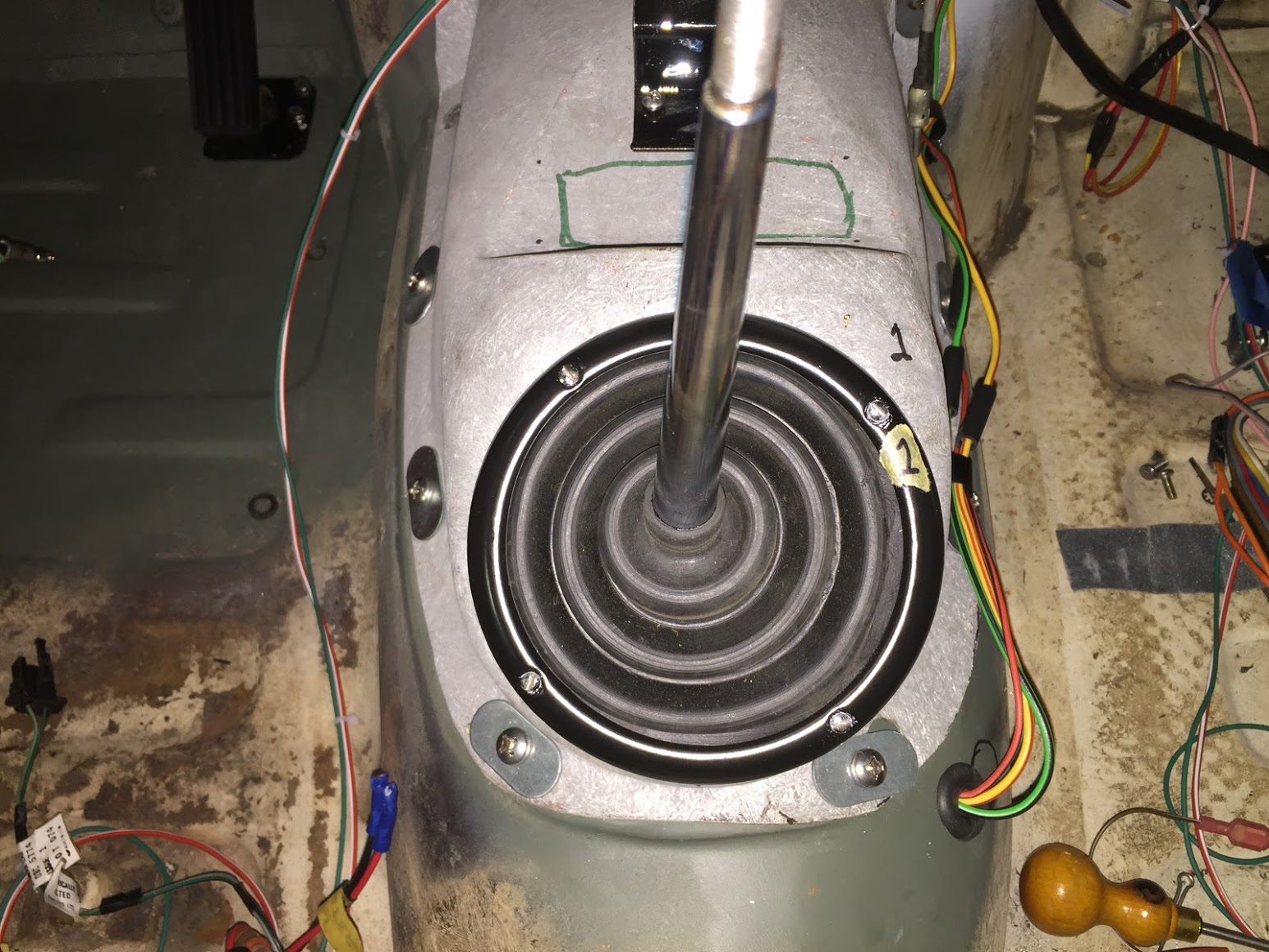
Heater Blower Firewall Seal Installed
Closed Cell Seals at Heater Flap & Hose Openings
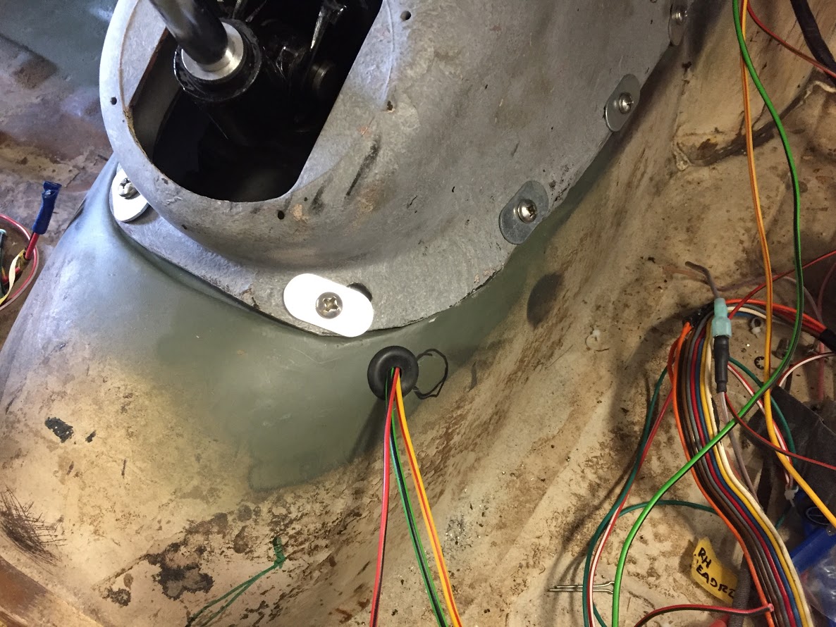
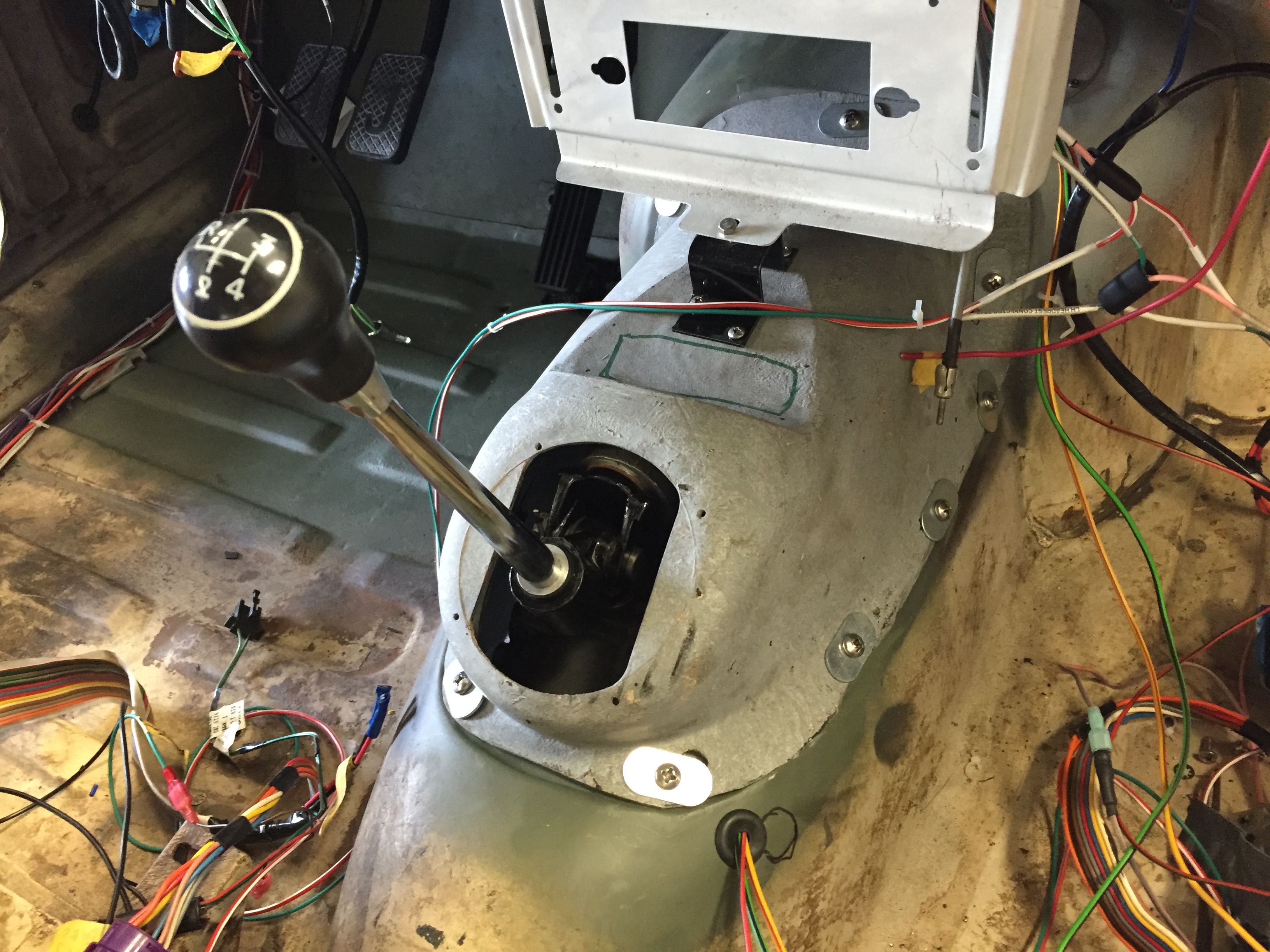
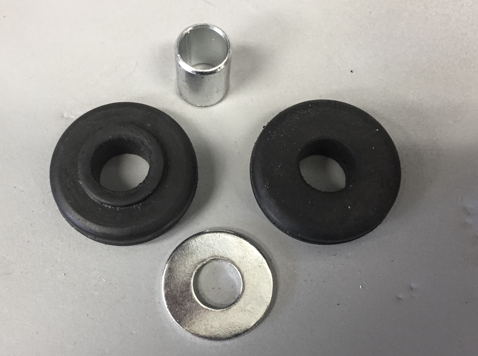
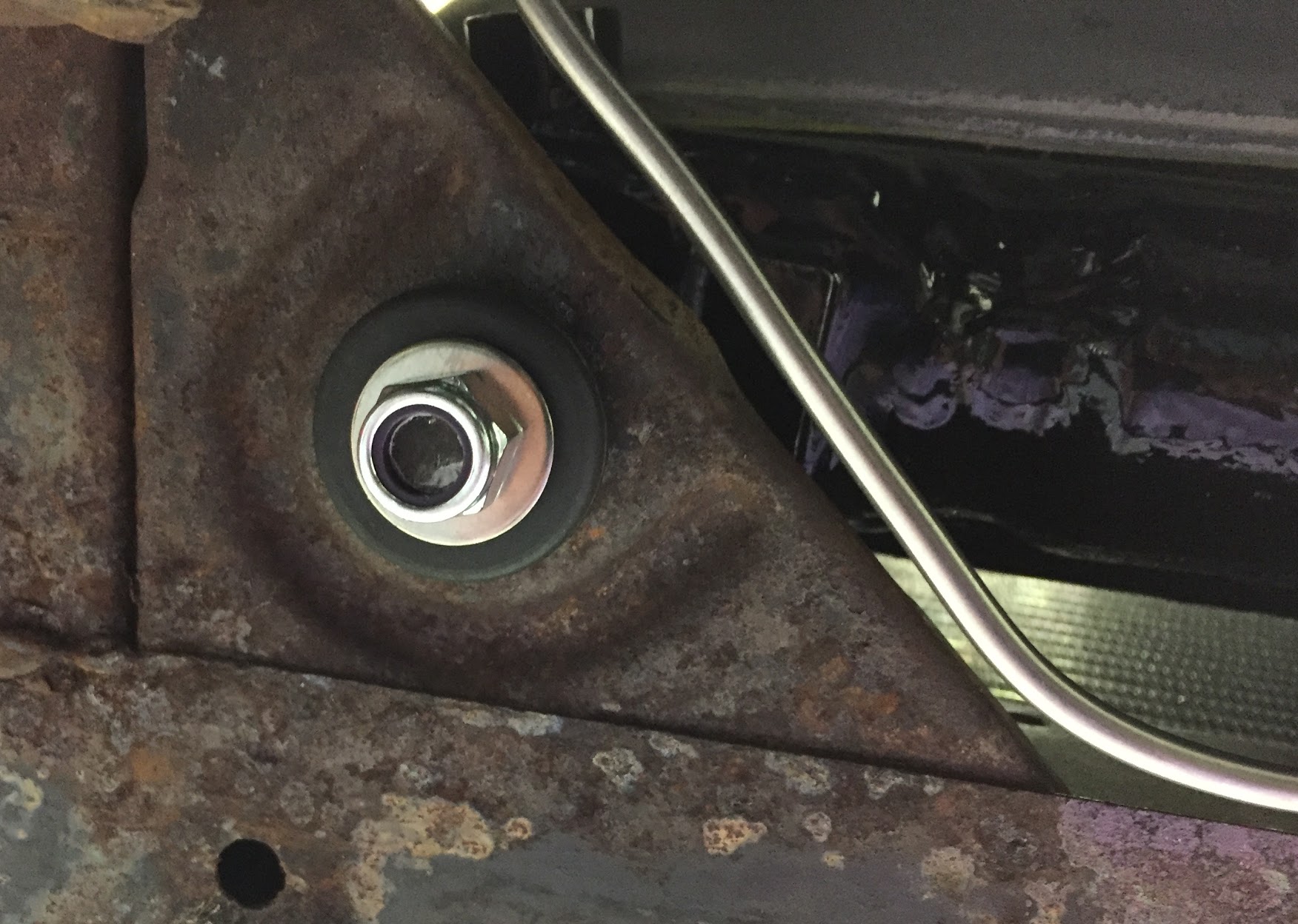
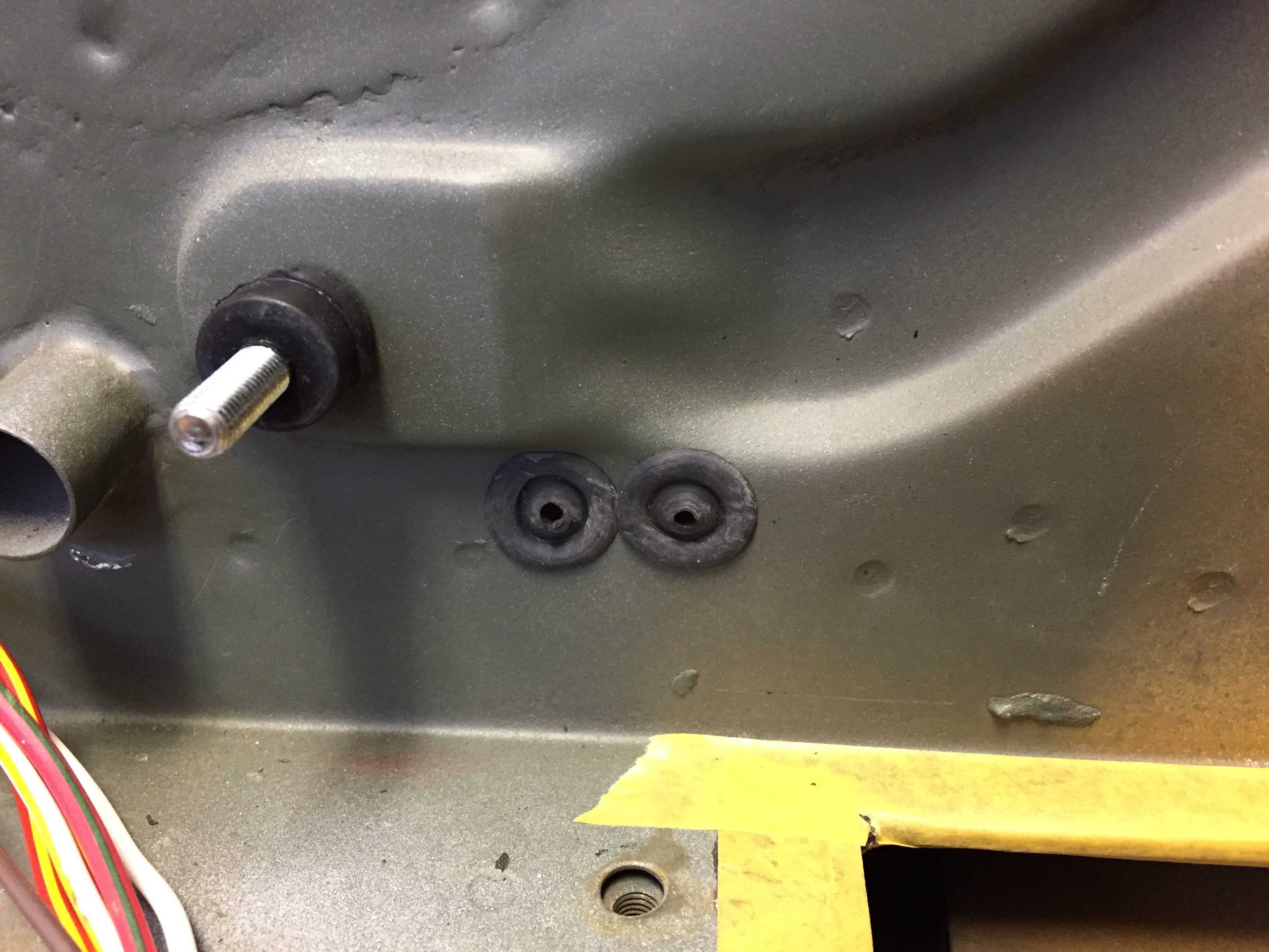
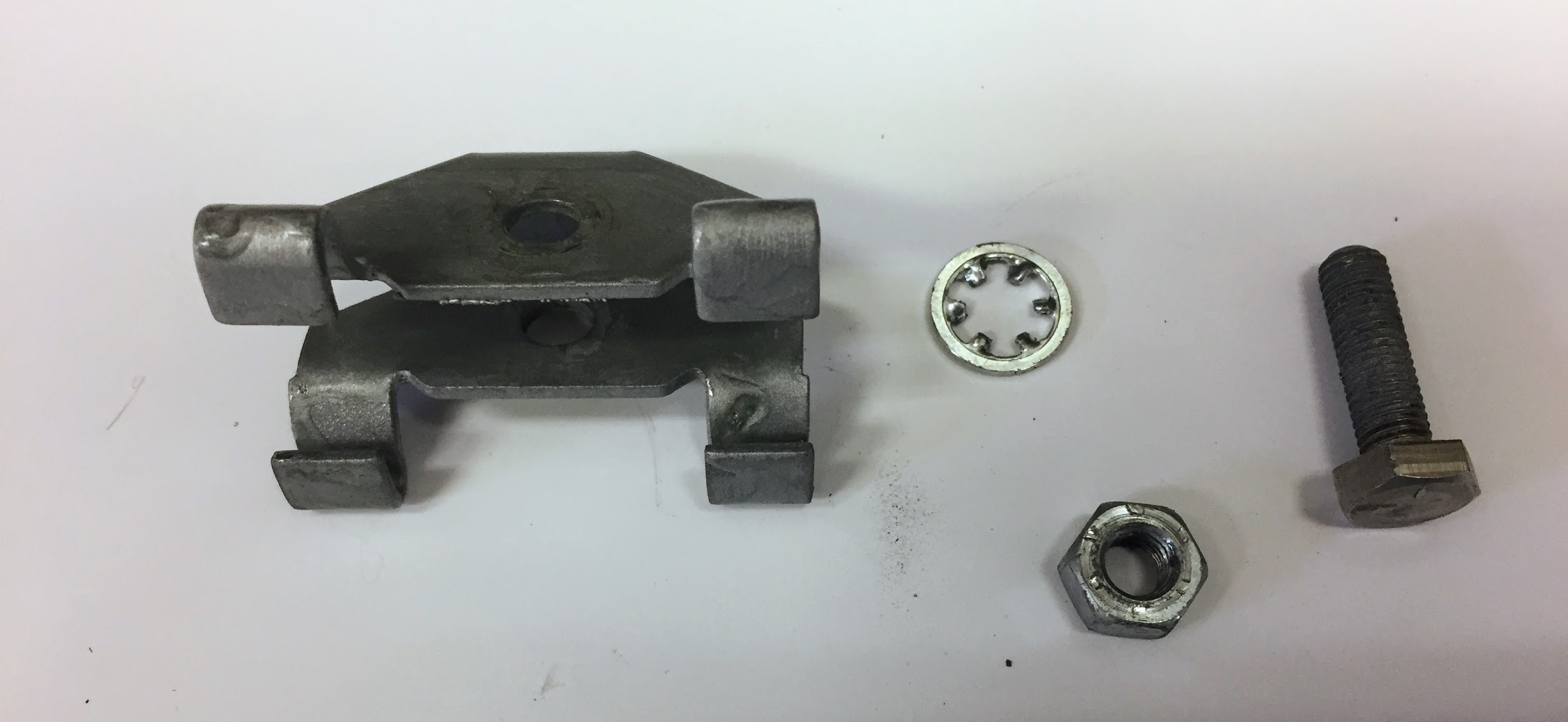
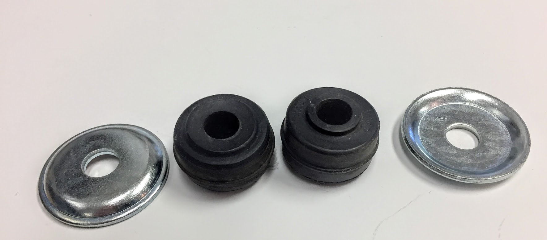
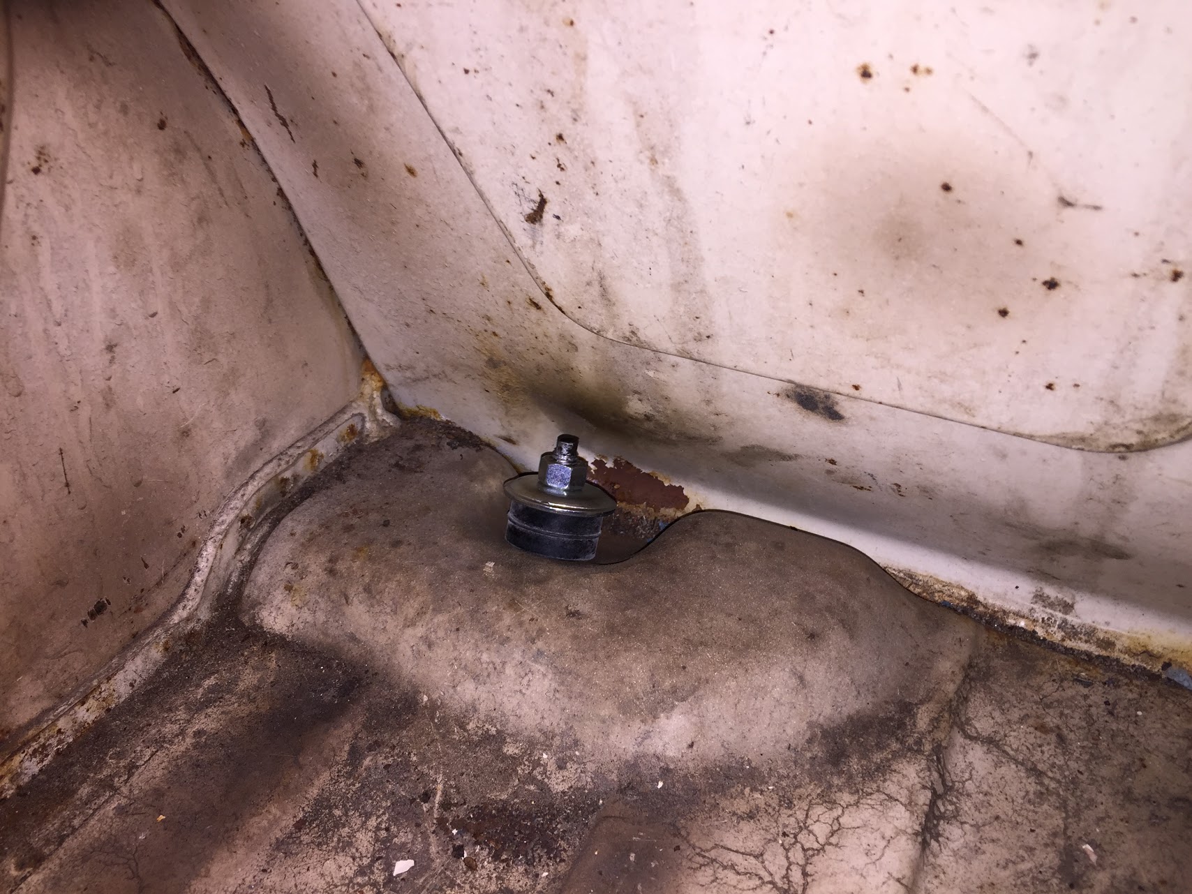
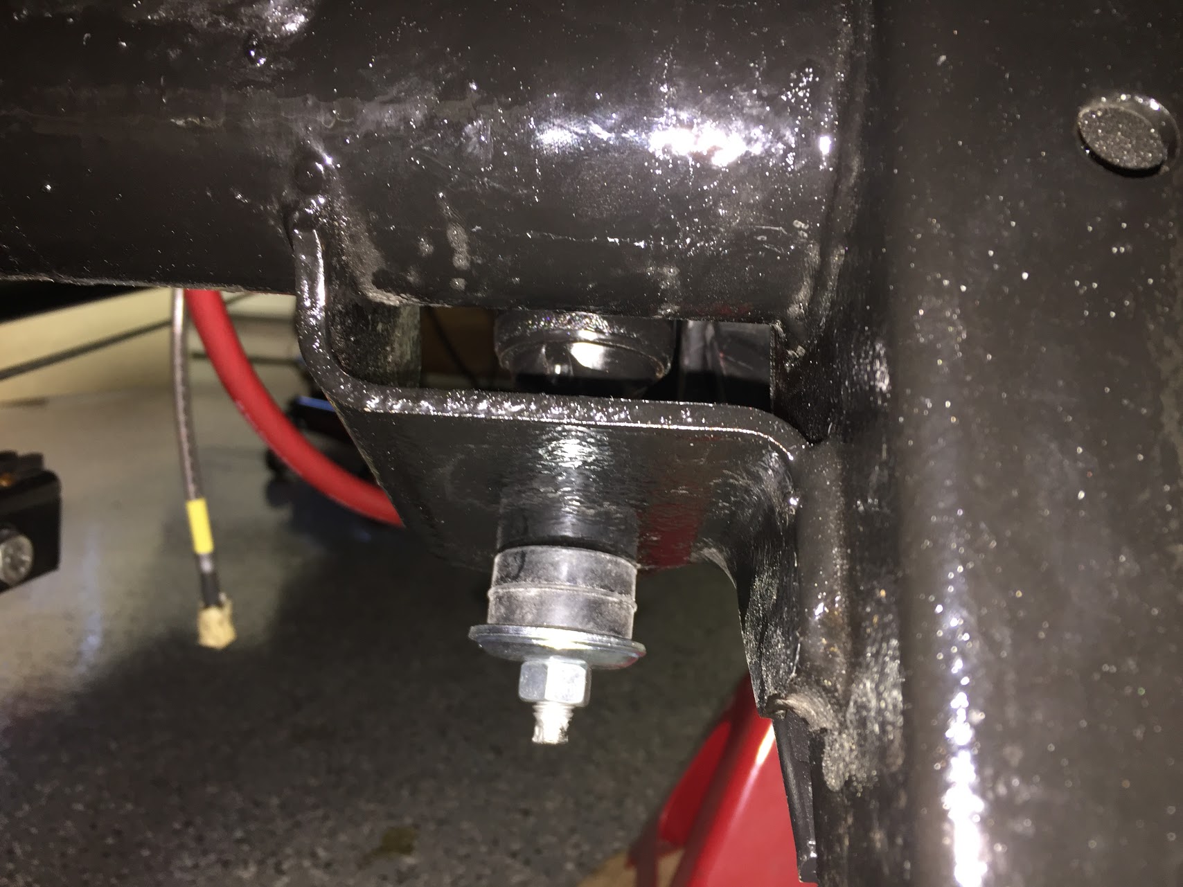
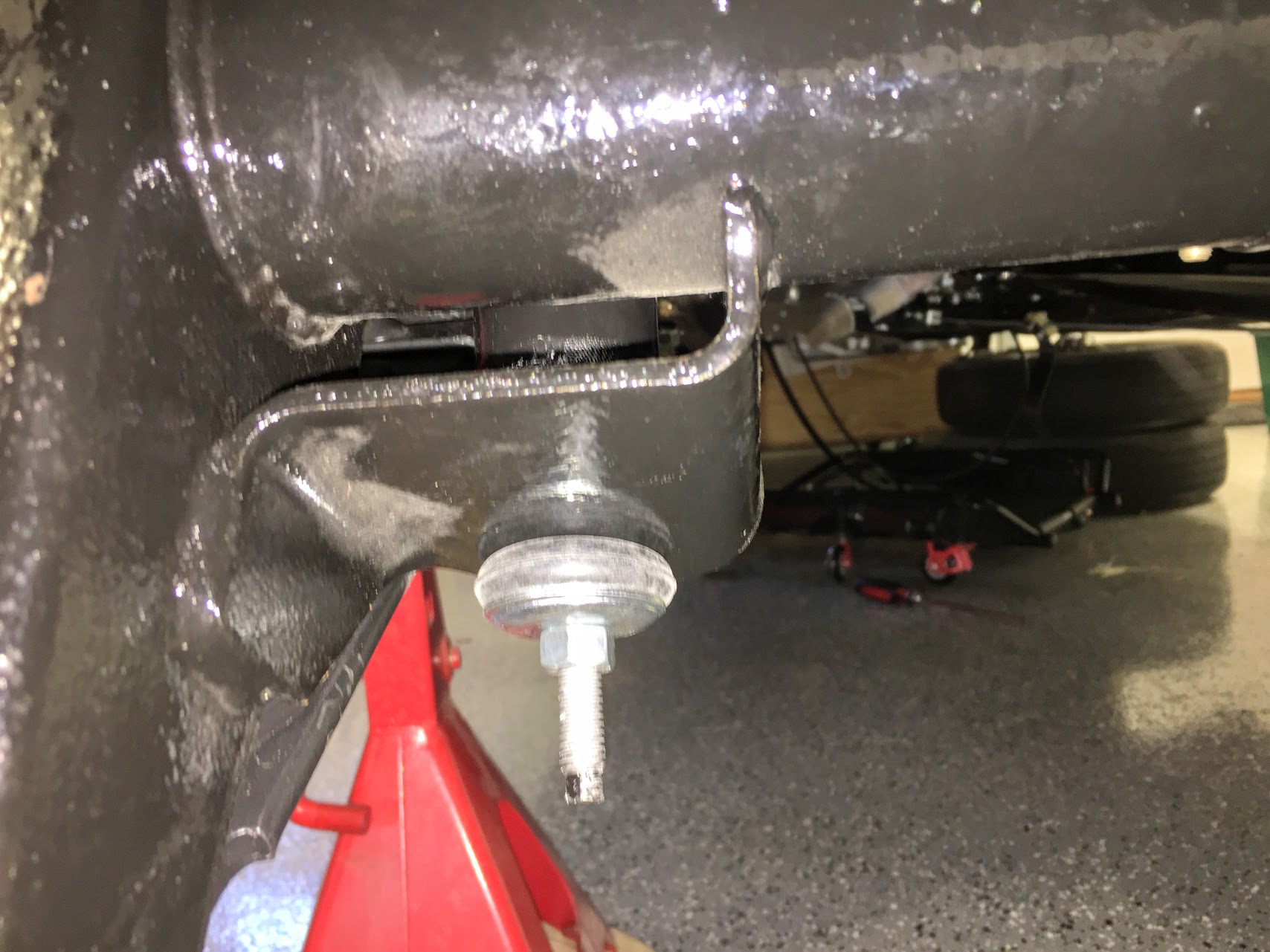
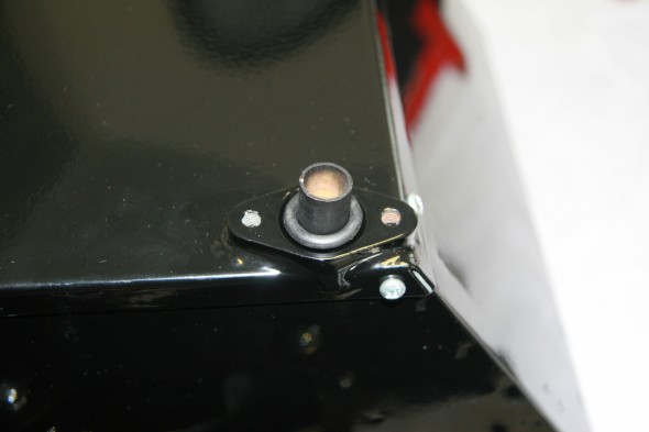
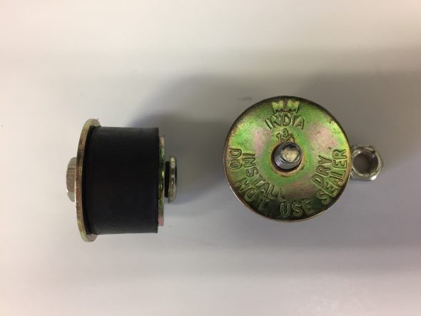
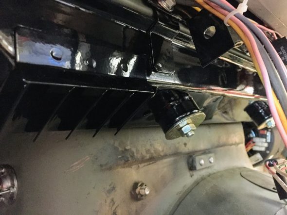
Three rubber “bobbins” serve as cushions and mounting posts for the heater box to the firewall.

Heater Mounting Stud and Heater Cable Firewall Grommets
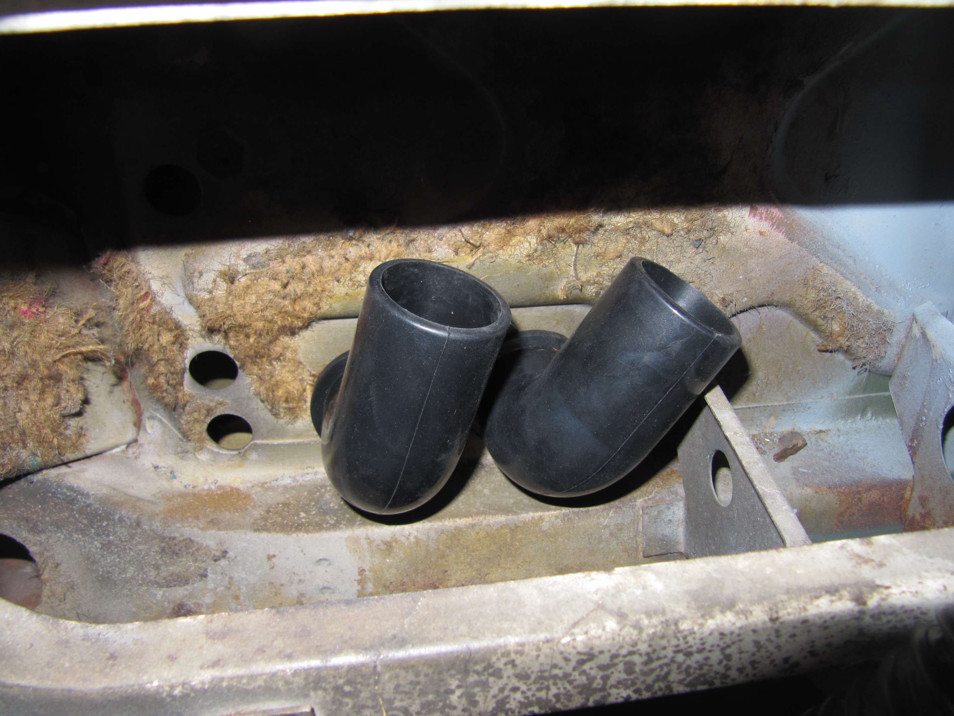
These are actually two 1/4″-28 hex head cap screws molded into each of the three rubber cushions. I used a 1/4″ – 28 x 1″ machine hex head screw on the lower right mount at the heater’s base and a 1/4′ – 28 x 1 1/4″ machine hex head screw on the lower left mount. Before placing the heater box in position I also installed the two firewall grommets for the heater control cables. These are visible in the image above. In the final assembly only one of these will be used due to the permanent closure of one of the circulation flaps as recommended by Clayton in their upgrade kit. Both heater hose rubber elbows were installed in the bulkhead.
Heater Box Installed
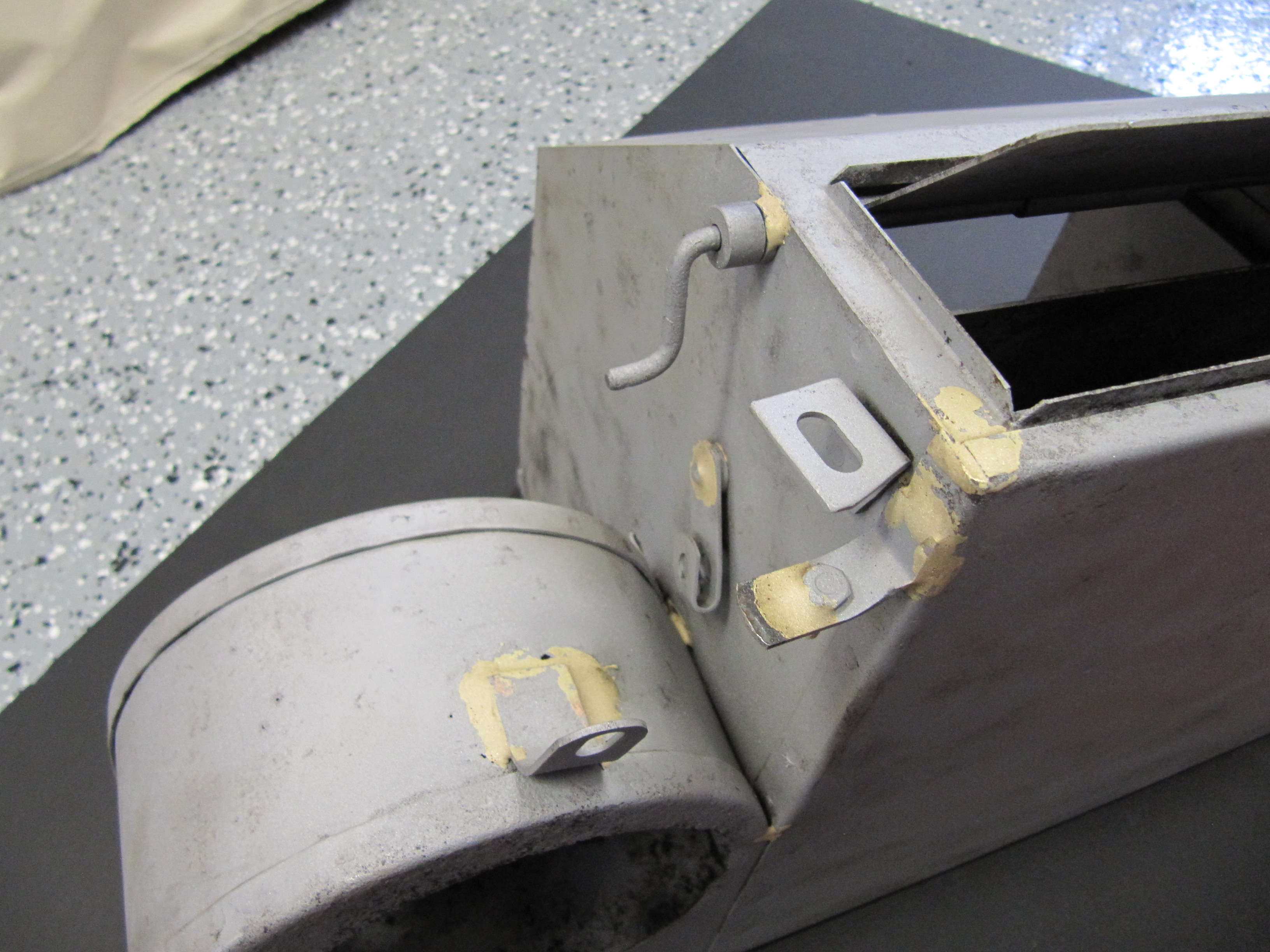
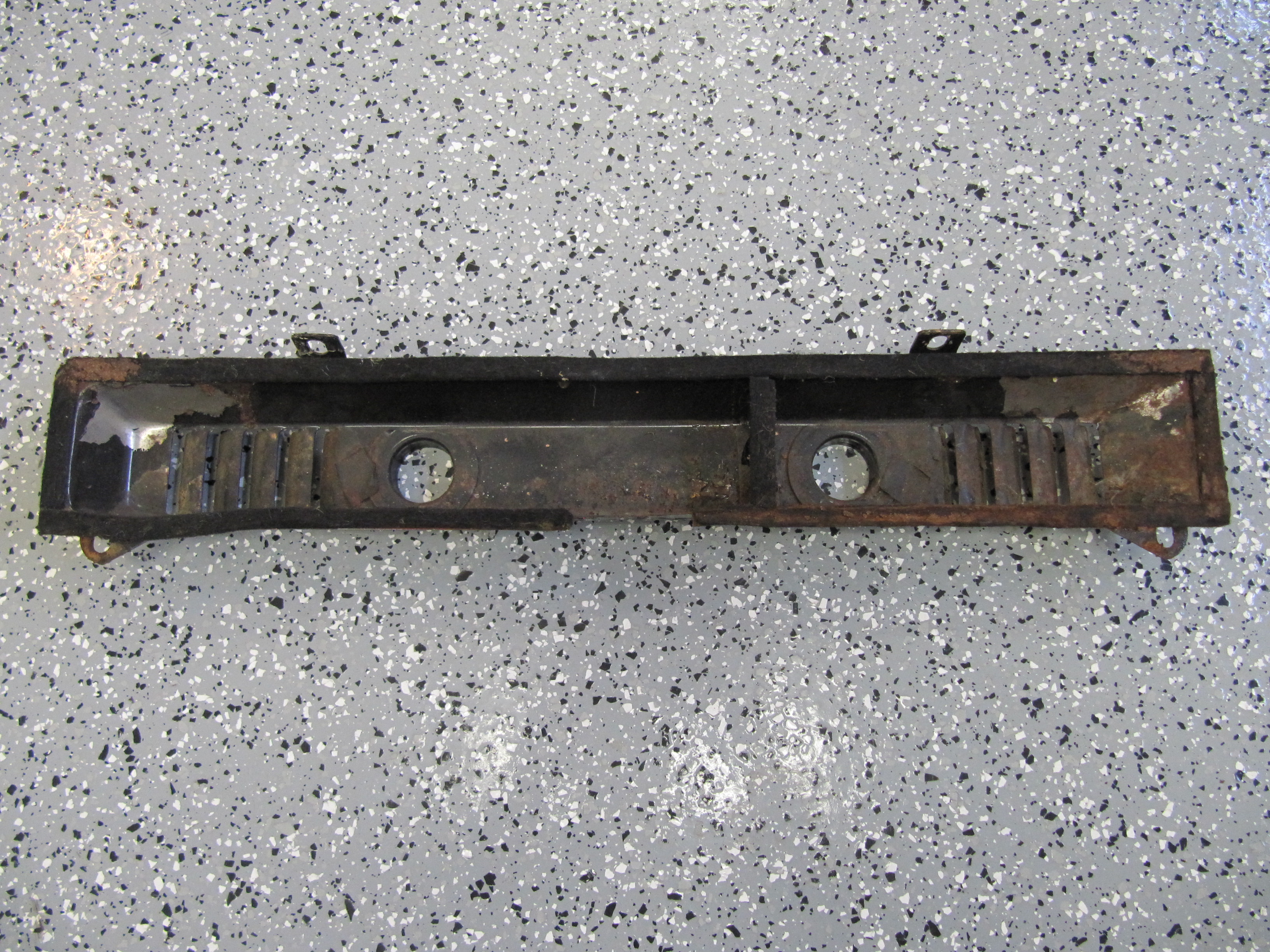
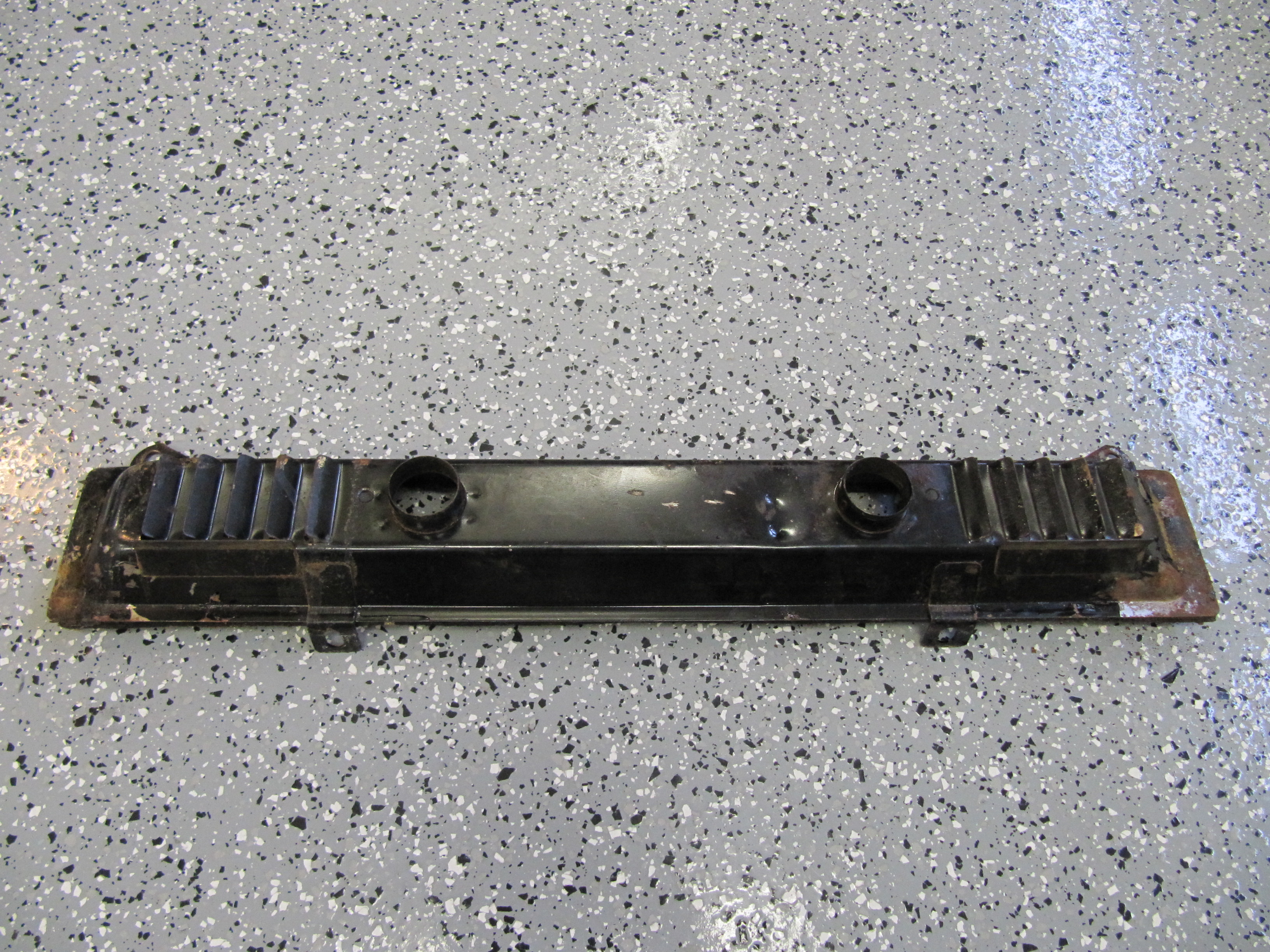
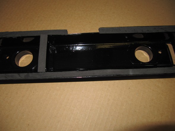
Air Distributor Box
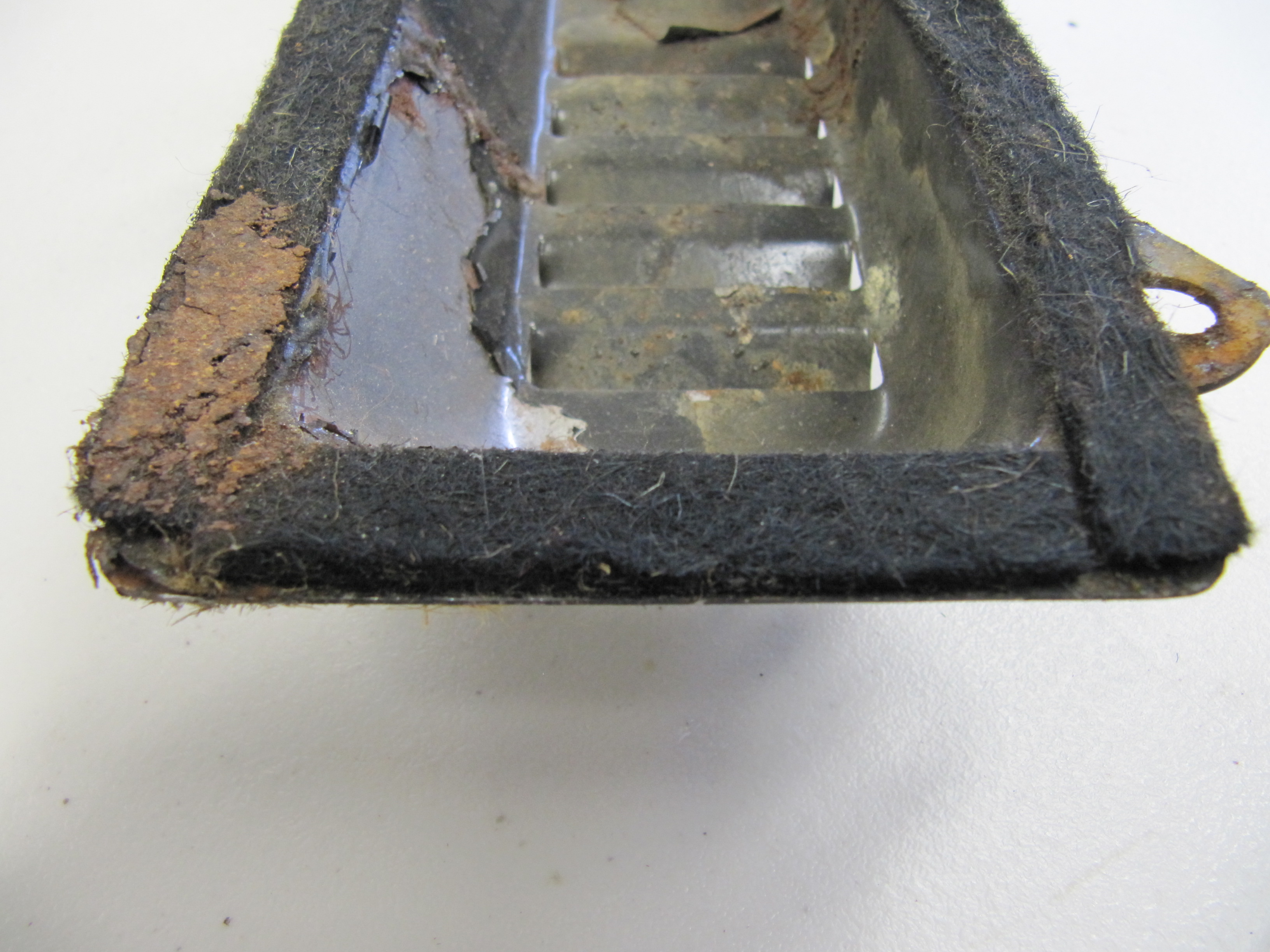
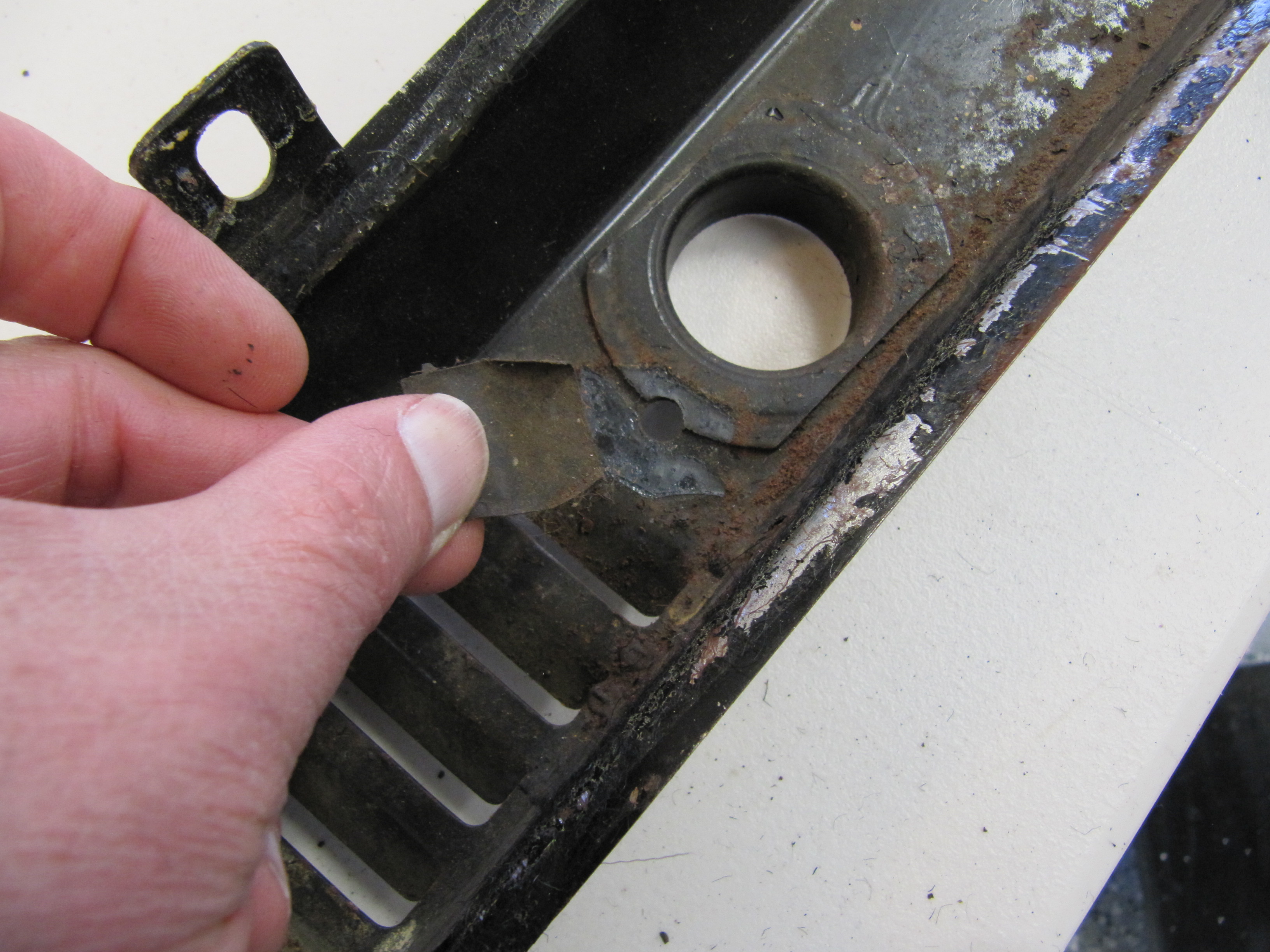
My next task was to clean up the air distributor box that is mounted in the center and below the dash with two 1/4″ – 28 x 1″ hex head bolts and two 1/4″ – 28 x 1/2″ hex head bolts with flat and shakeproof washers. As the images show, a felt gasket is glued to the edges of the box. A small piece of black electrician’s tape was found placed over two holes in the box. The box was blasted with aluminum oxide and powder coated gloss black.
Air Distributor Box
Air Distributor Box
Felt Gasket
Tape Blocking Holes

Tape Blocking Holes
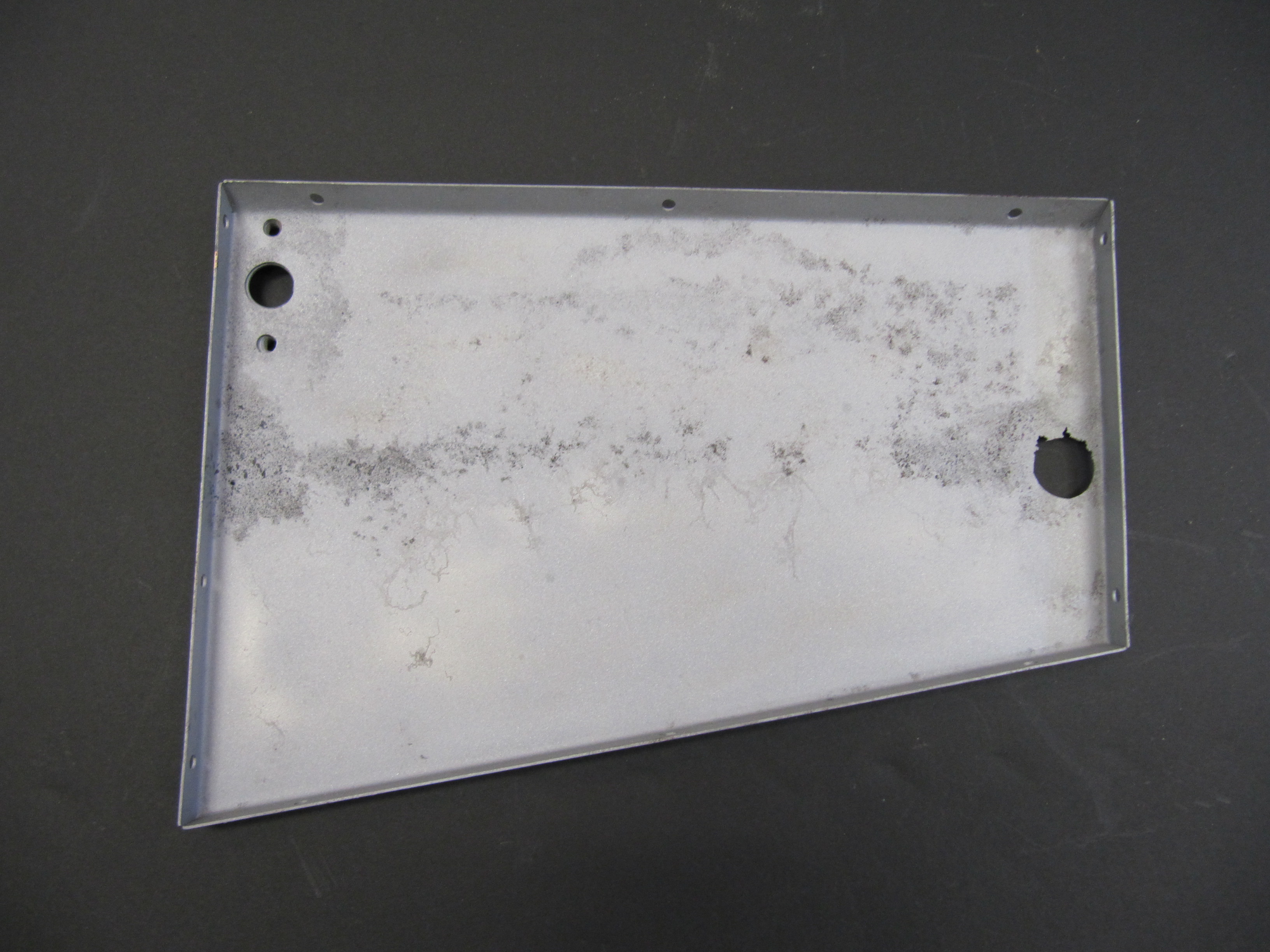
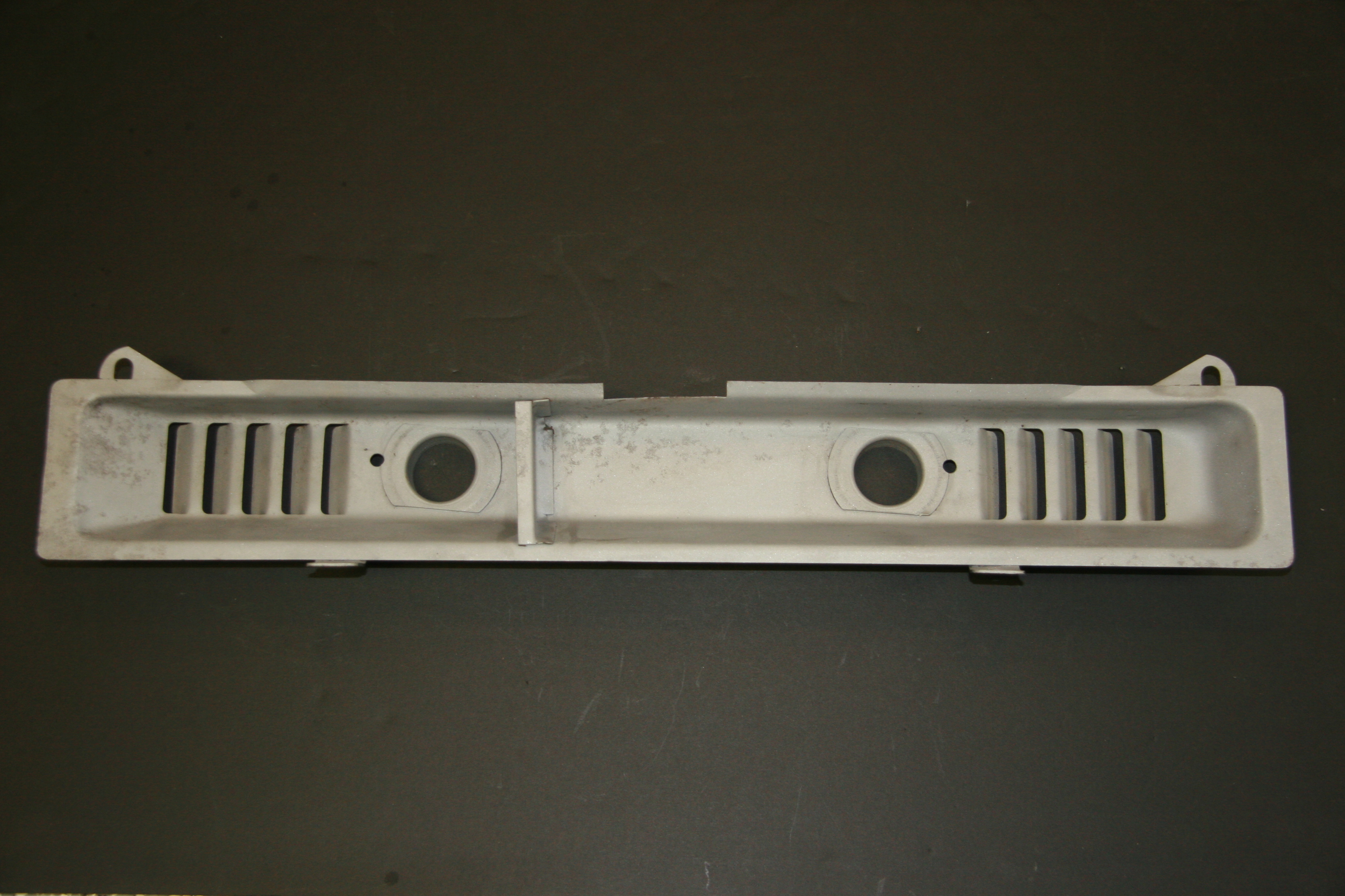
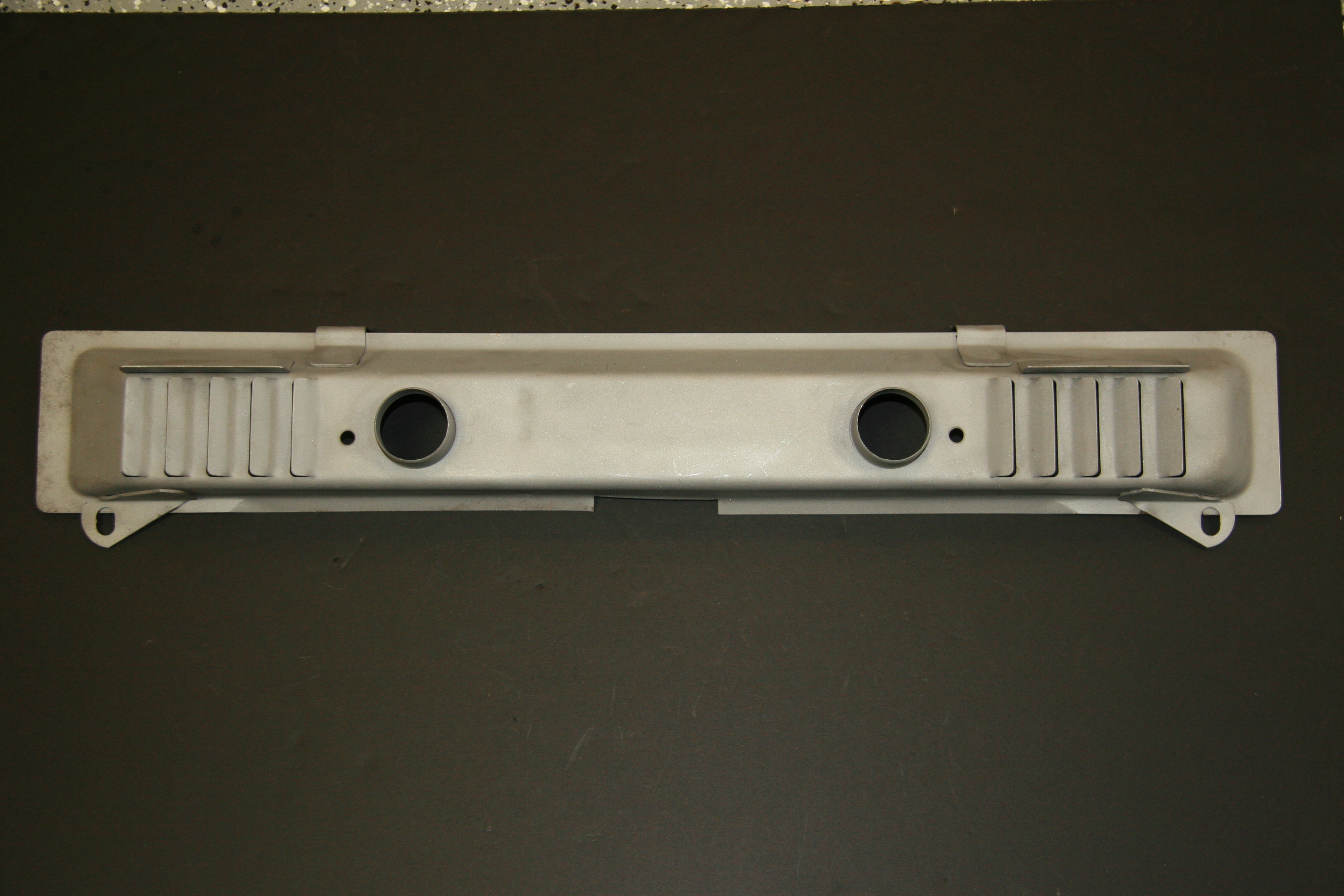
I media blasted the box to prepare it for powder coating:
Clean Air Box
Clean Air Box

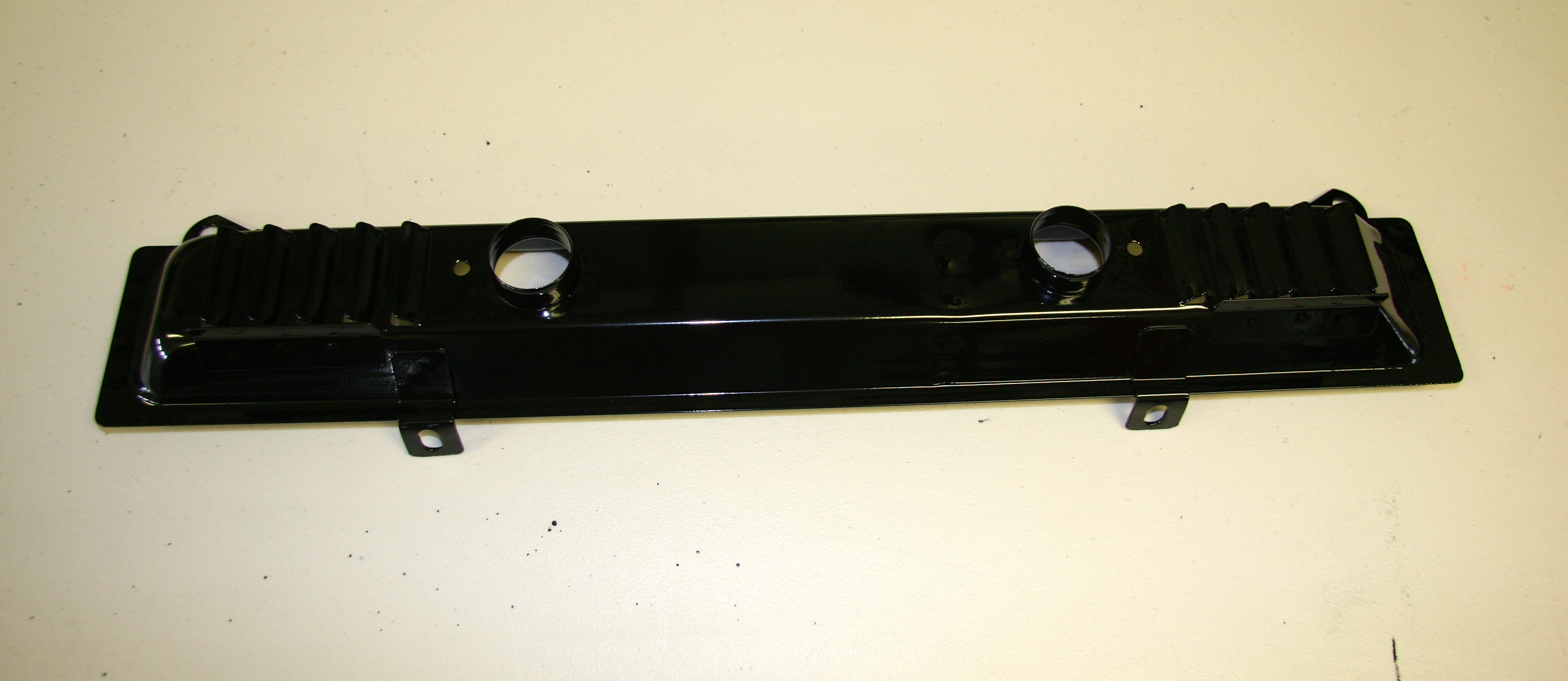
Powder Coated Air Distributor Box
To prepare for the trial installation of the Air distributor Box, I cleaned the mounting surfaces and applied some self-etching primer. This will, of course be removed when the car is blasted.
Mounting Location for the Air Distributor Box
The Air Distributor Box had a felt gasket around its perimeter when I removed it from the car. I made and glued a closed cell foam gasket to the Box before mounting.

Foam gasket for the air distributor box
Air Distributor Box Foam Gasket
Air Distributor Box Installed

Air Distributor Box Installed
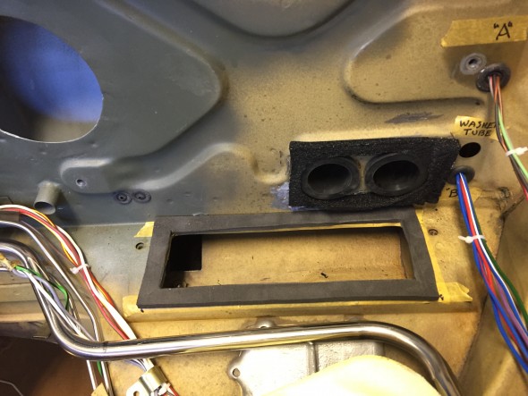
At the suggestion of Eric Kriss, I also concluded that given the somewhat poor performance of the MK2 heating system, it made little sense to send heat to the rear of the car. What heat was produced would be best restricted to the front seats! He closed the two vent outlets in the air distributor box with expandable rubber plugs, and I followed his lead. I picked up two 1-3/8″ plugs from my local ACE Hardware and they work perfectly.
Expandable Plugs for Air Distributor Box
Expandable Plugs Installed in Air Distributor Box
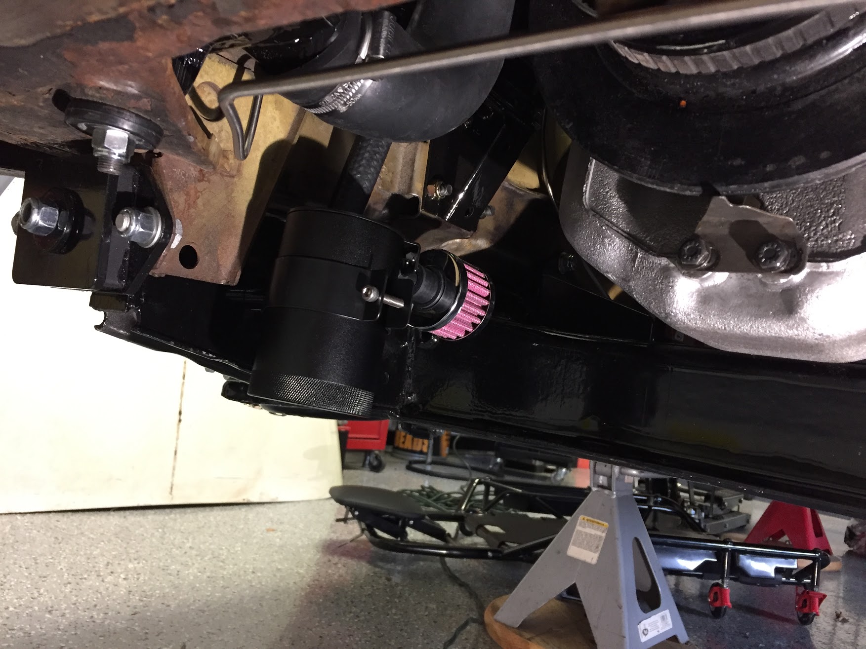
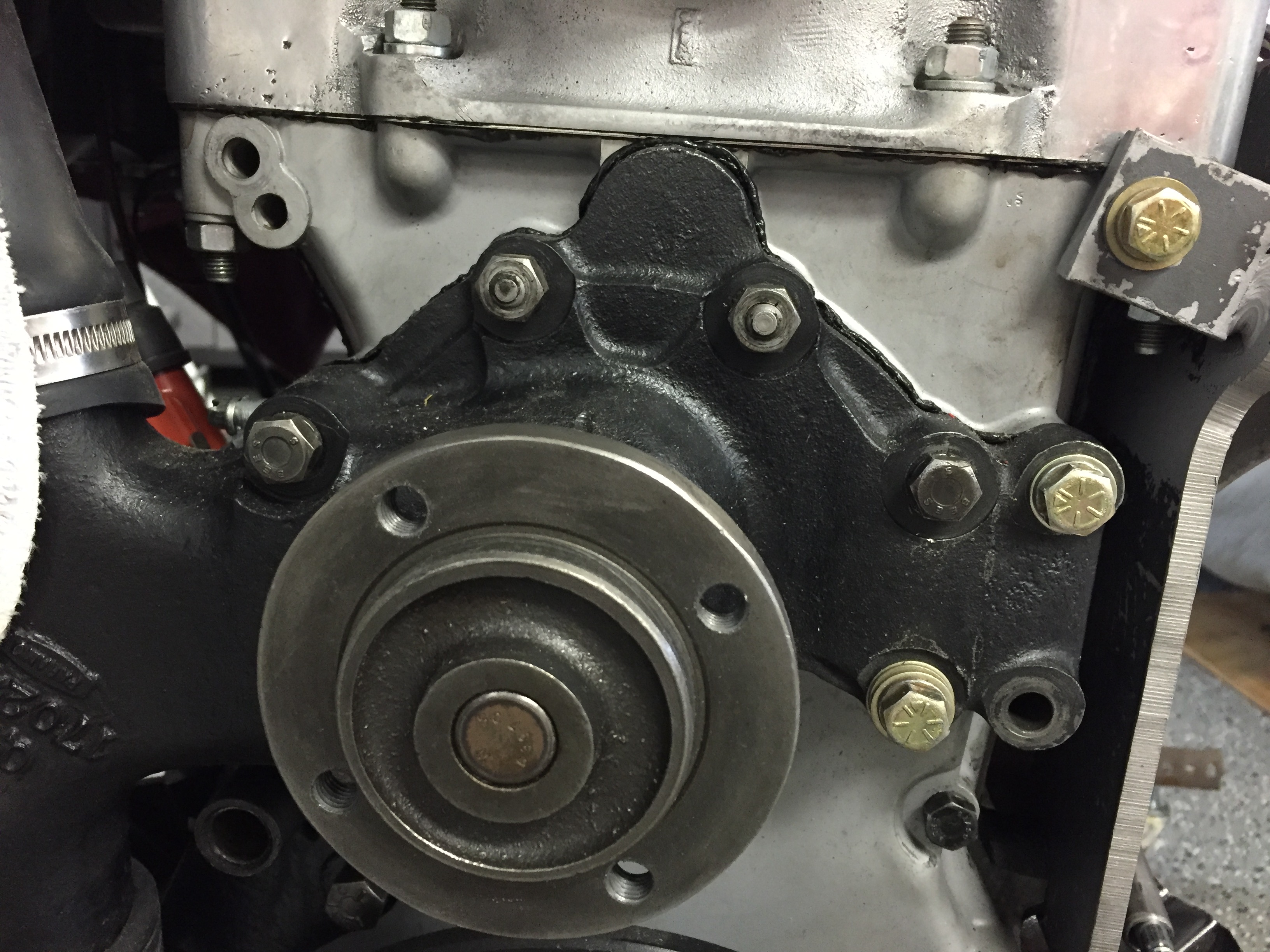
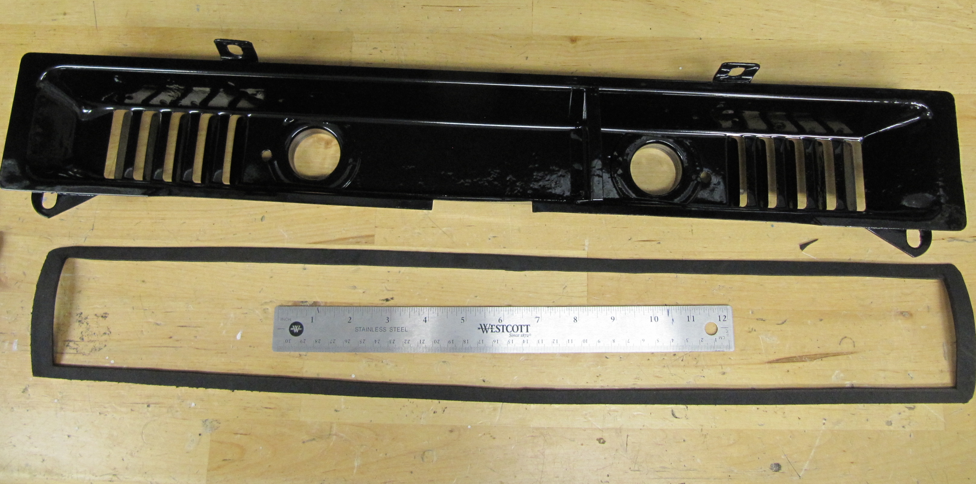
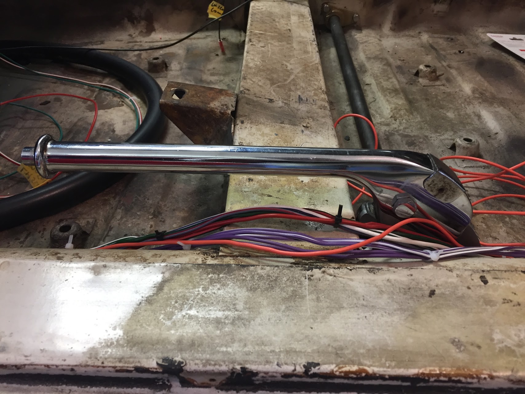
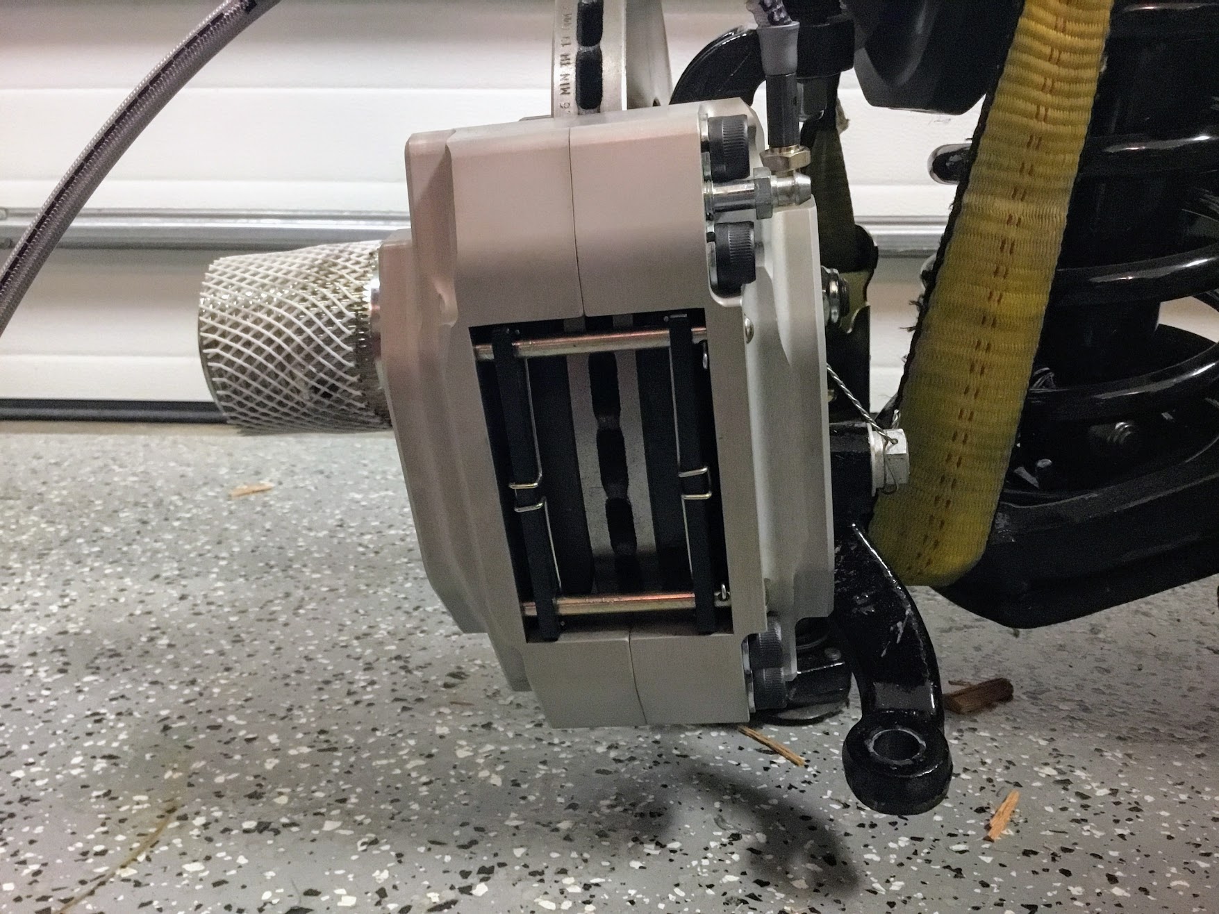
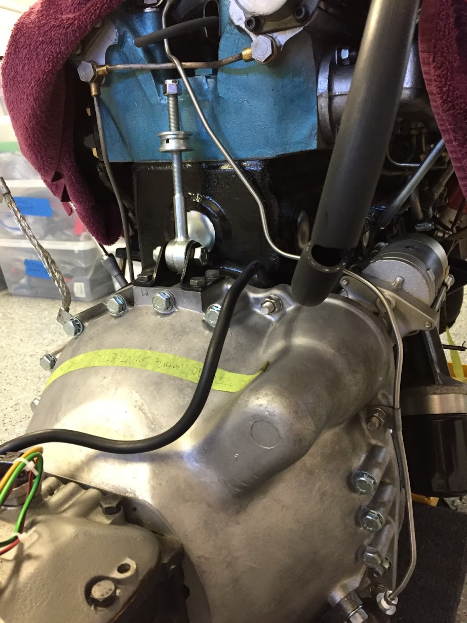
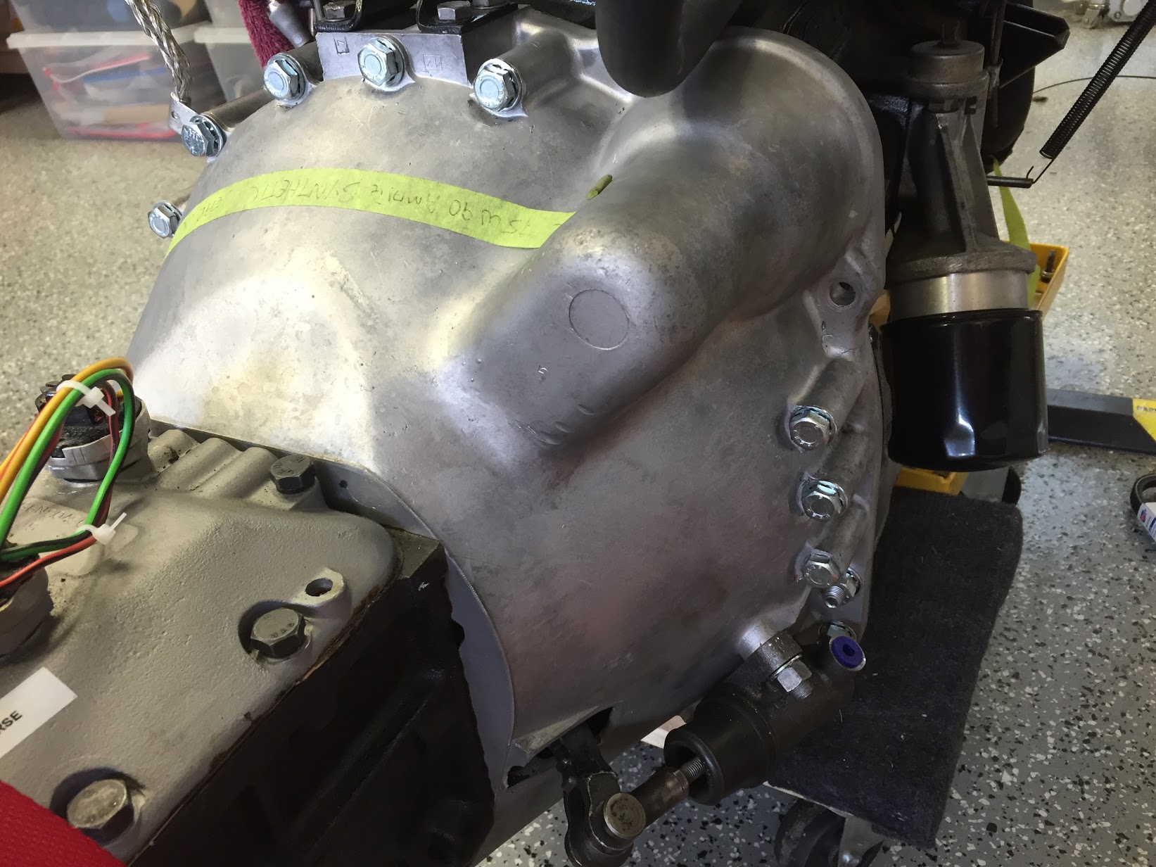
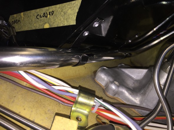
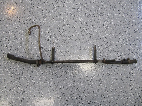
Front Heater Return Pipe
Hot Water Circulation
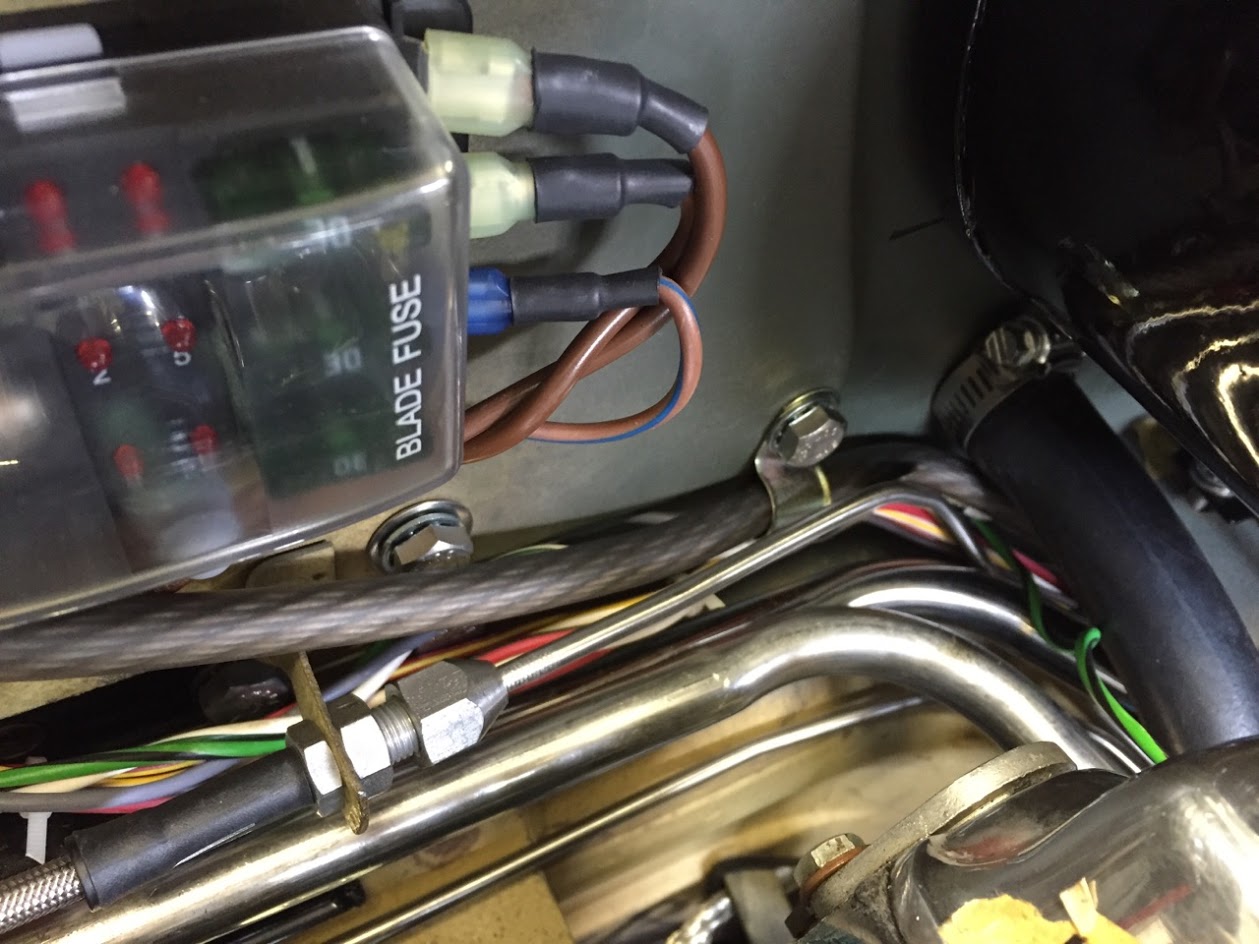
The hot water circulates through the heater via steel pipes and rubber hoses. Though not as original, I used stainless steel pipes available as a kit form SNG Barratt or XKs Unlimited. They should be painted black but I am going to just leave them unpainted since they would probably just get scratched anyway.The Rear Return Pipe, on Scuttle, At Rear of Cylinder Block connects to the Front Return Pipe and then to an adaptor at the Water Pump. The pipe is secured by a clip bracket on the firewall and by two clips on the heater box:
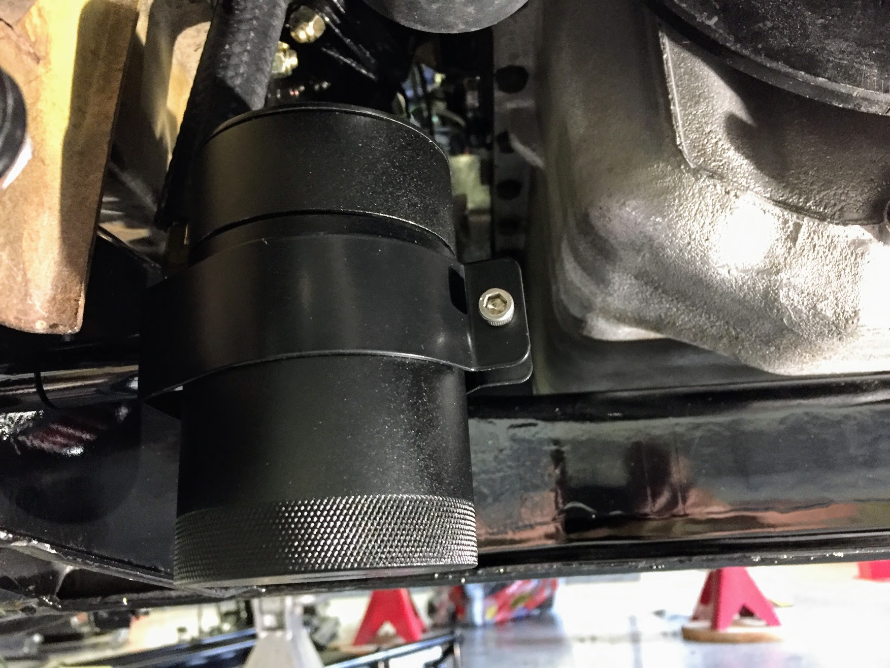
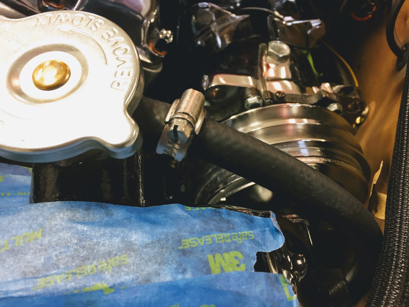
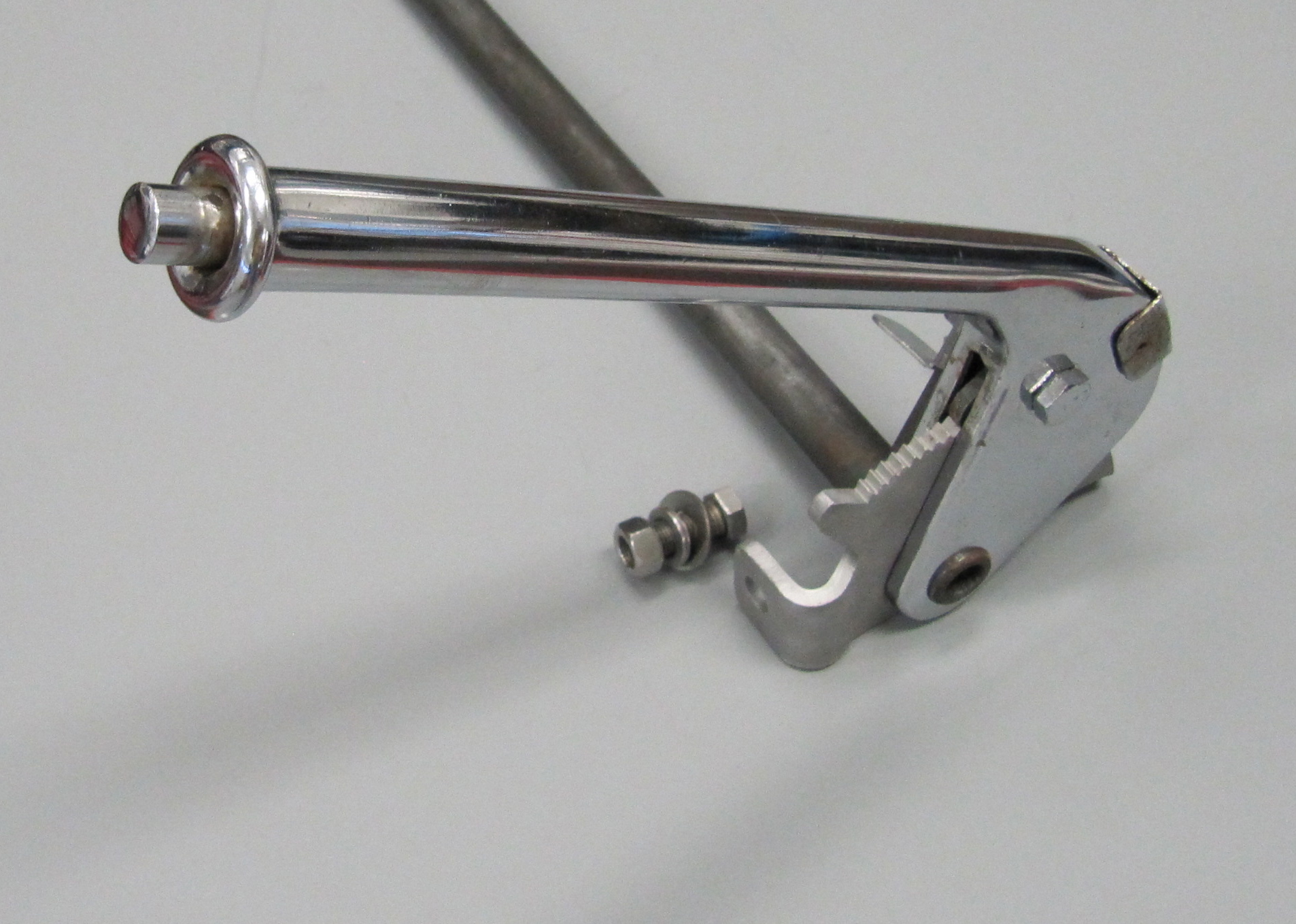
Heater Pipe Clip
Heater Pipe Clipped to Heater Box
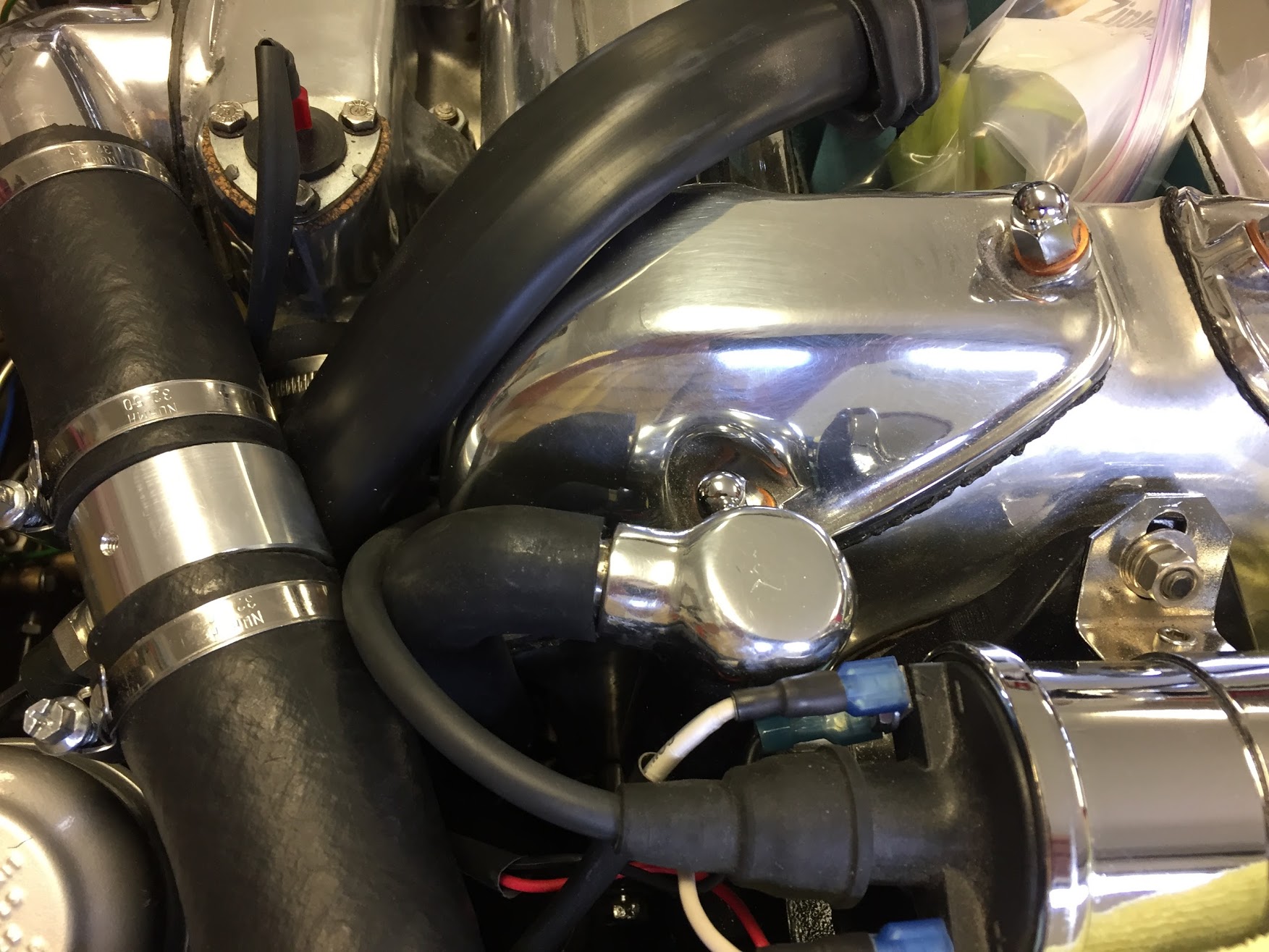
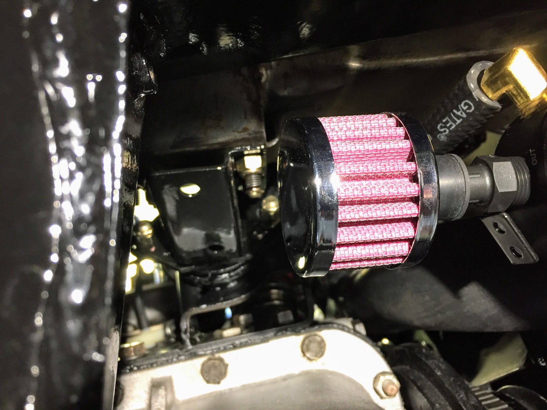
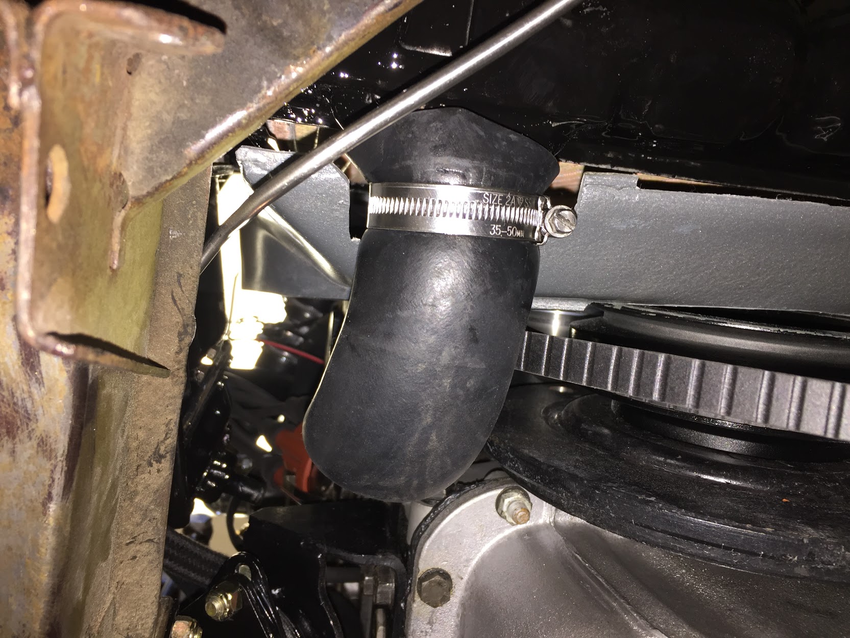
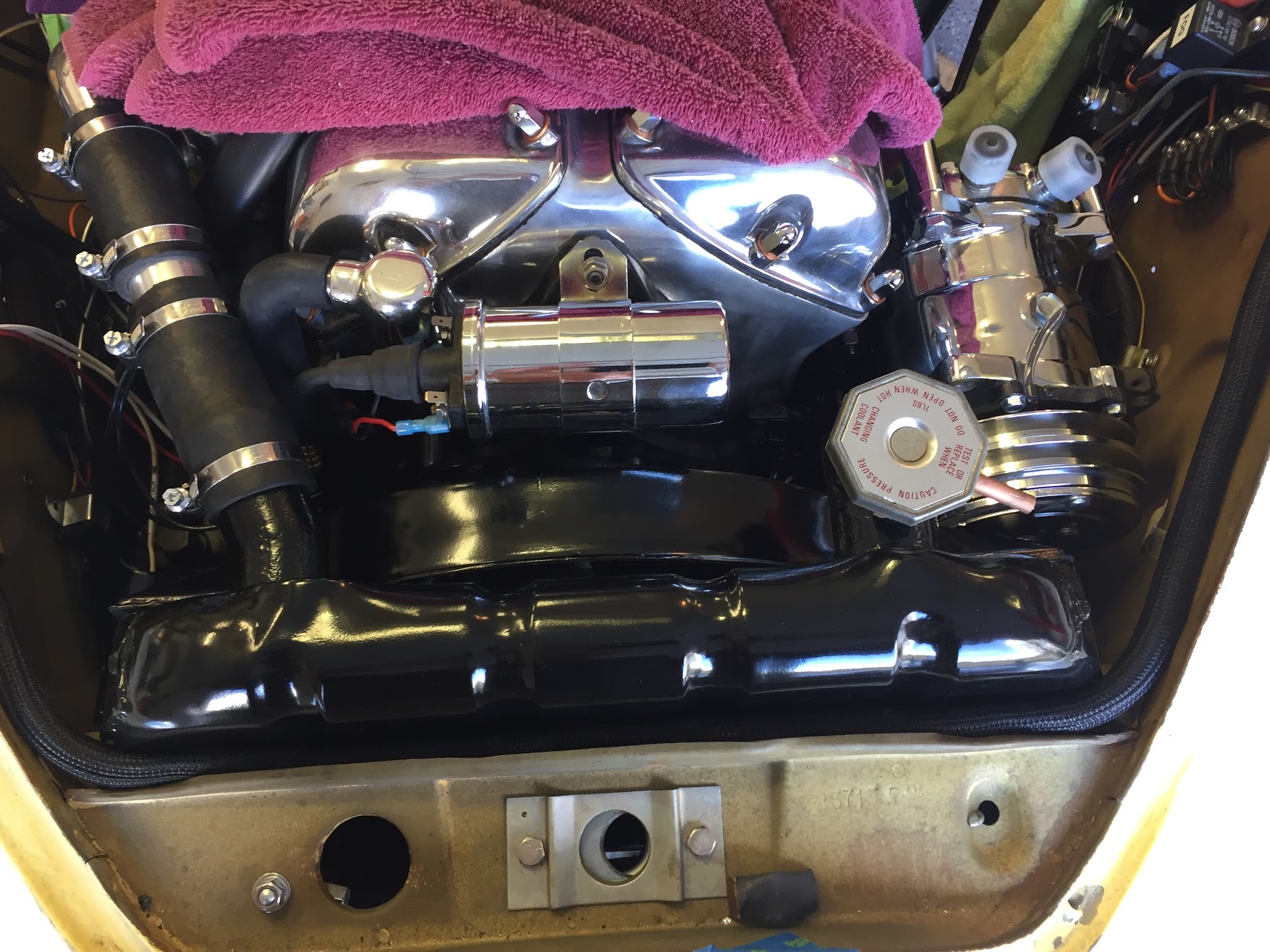
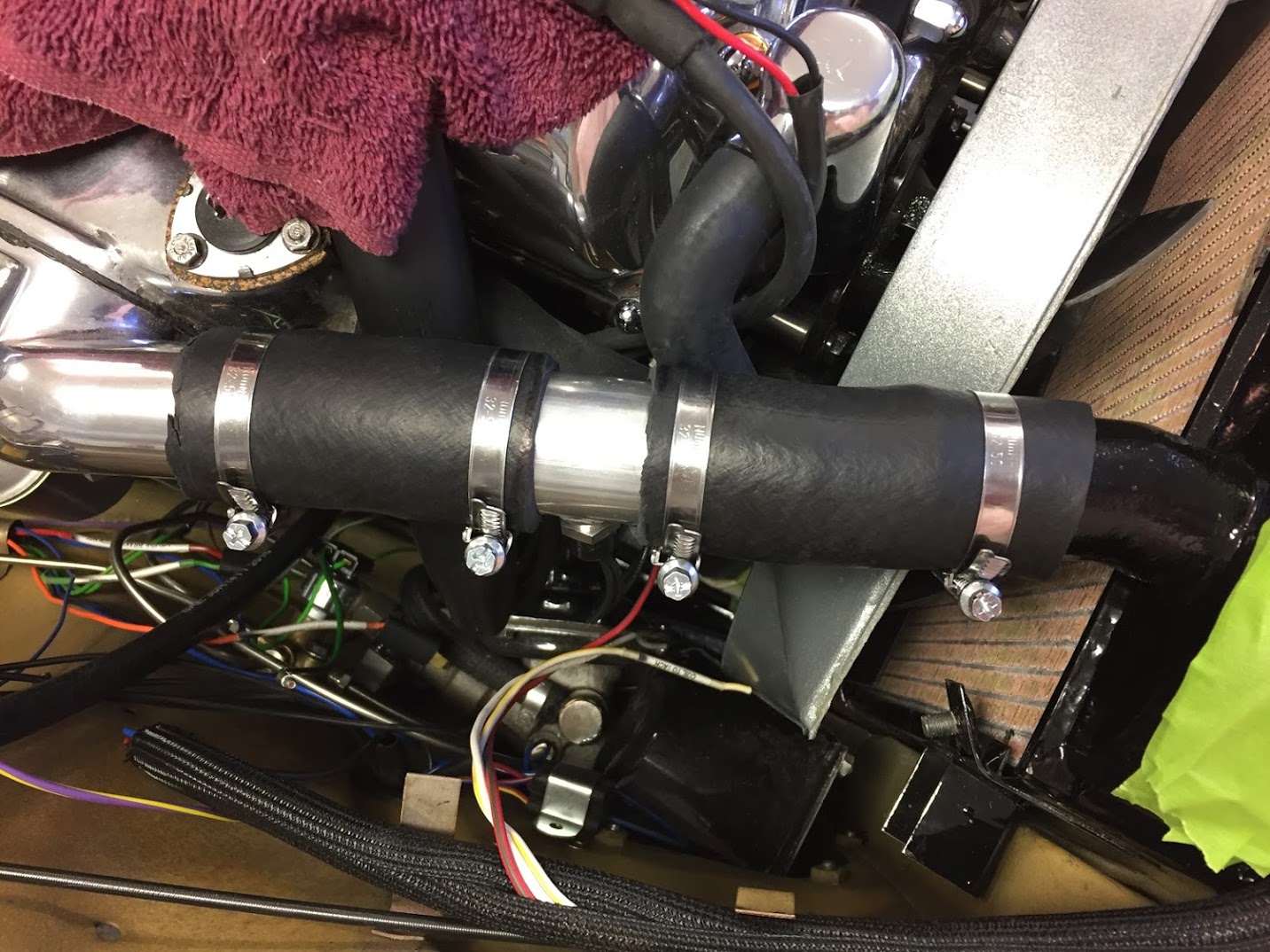
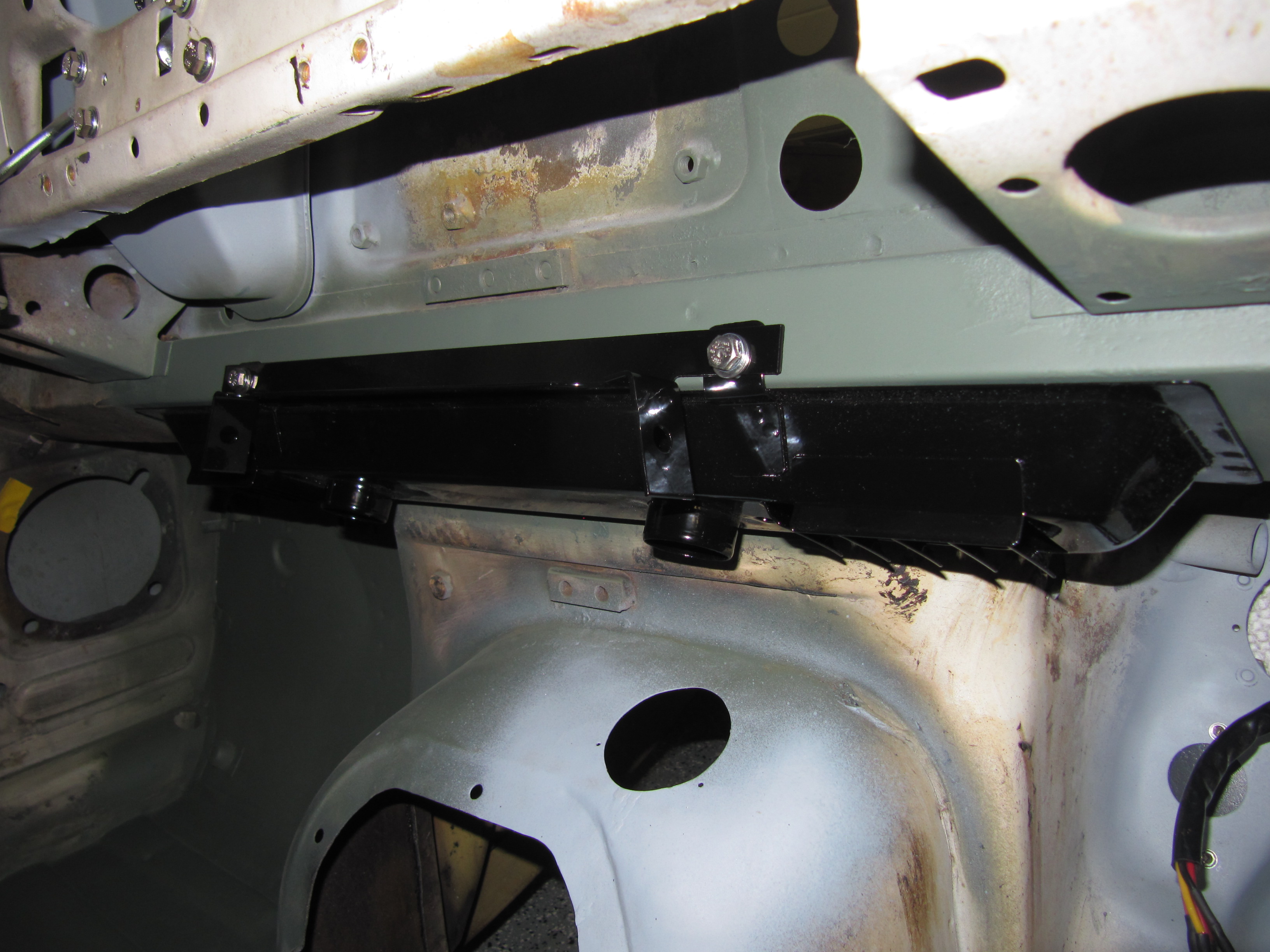
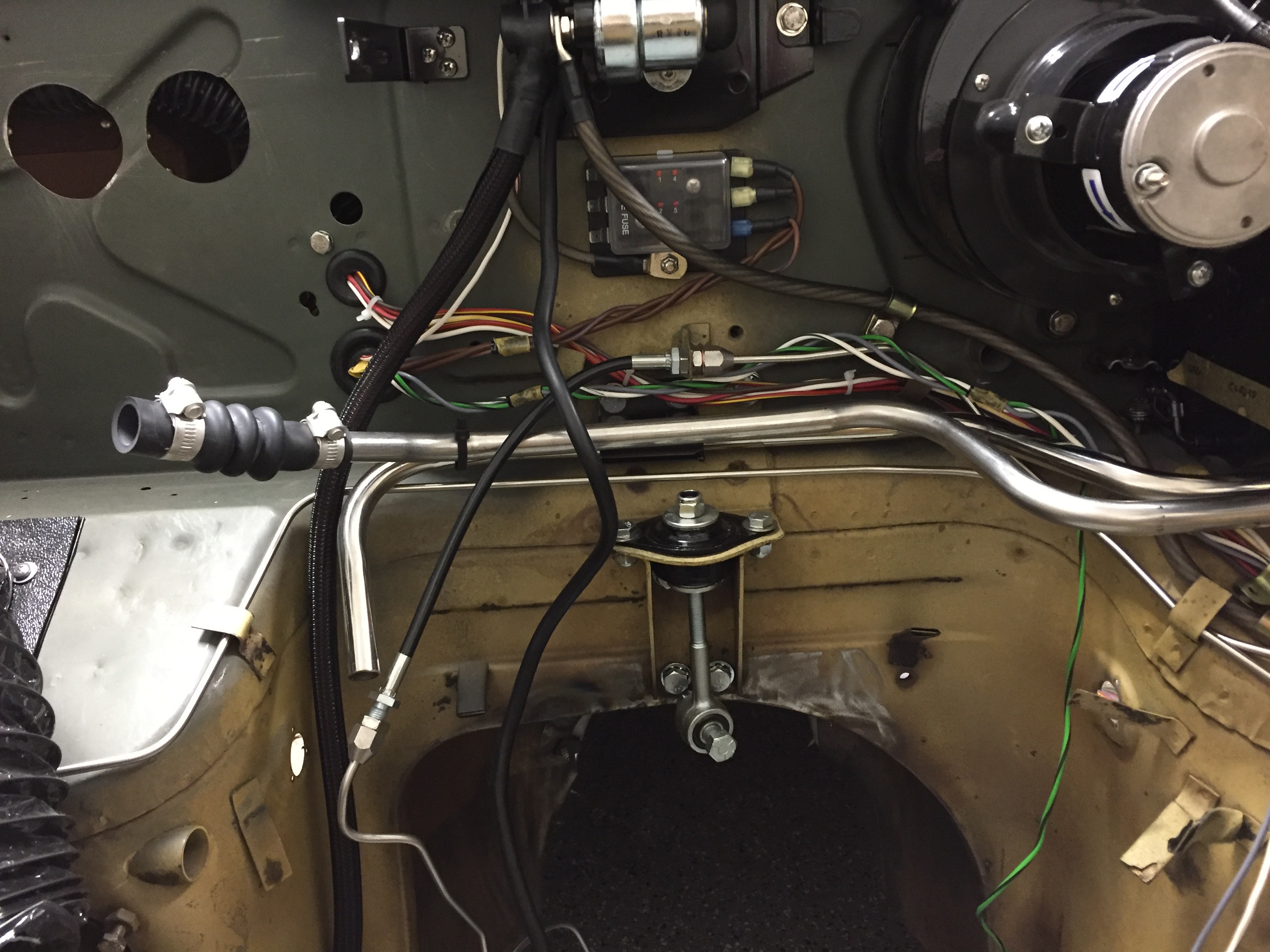
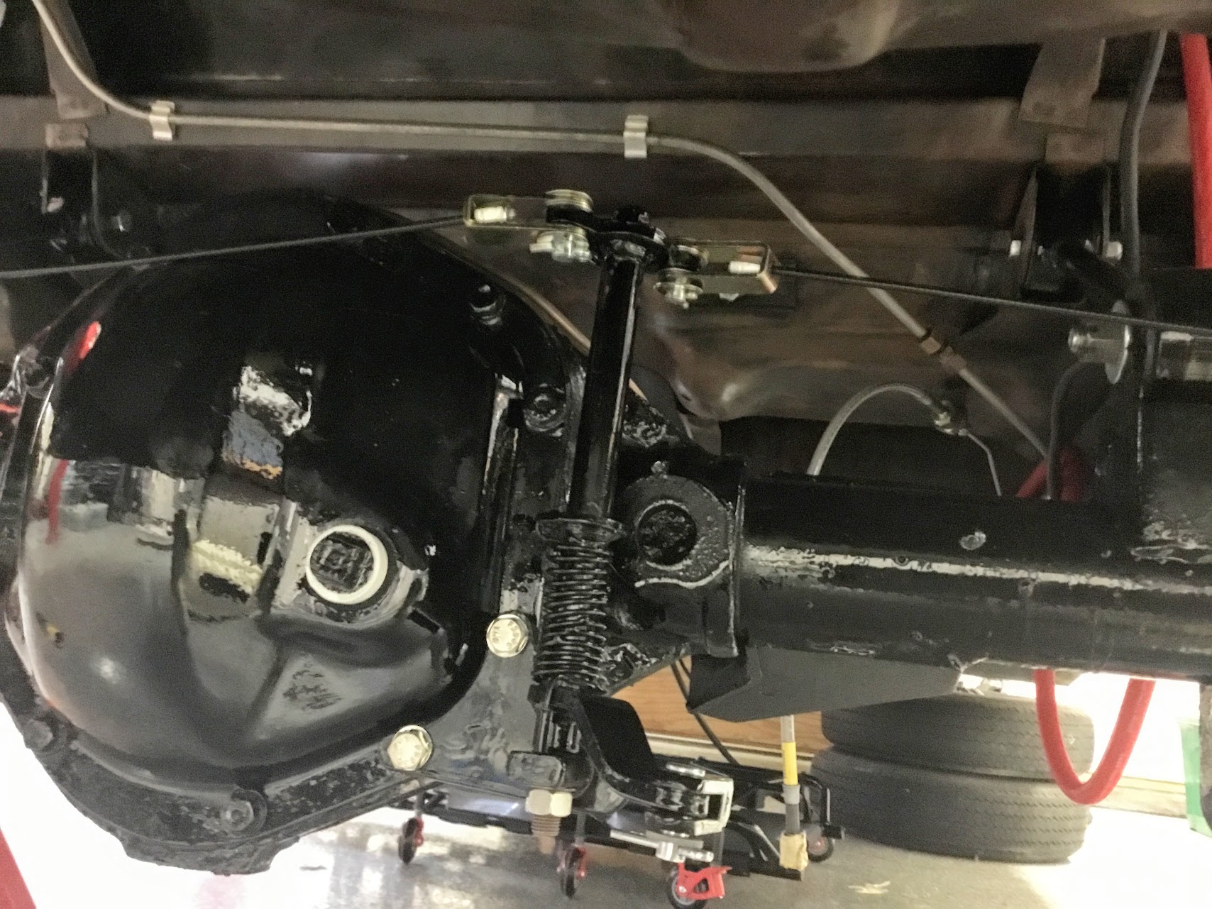
The feed pipe via a rubber elbow connects to the heater radiator inlet pipe, and to the water outlet on the intake manifold. The image below shows two of the pipes installed in the engine bay and connected to the heater:

Rear Heater Pipes Installed
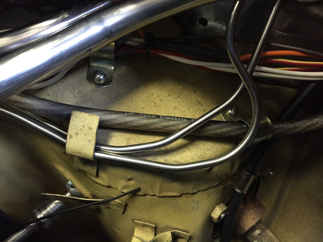
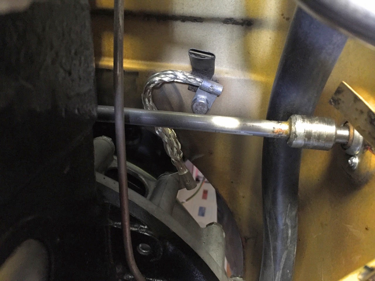
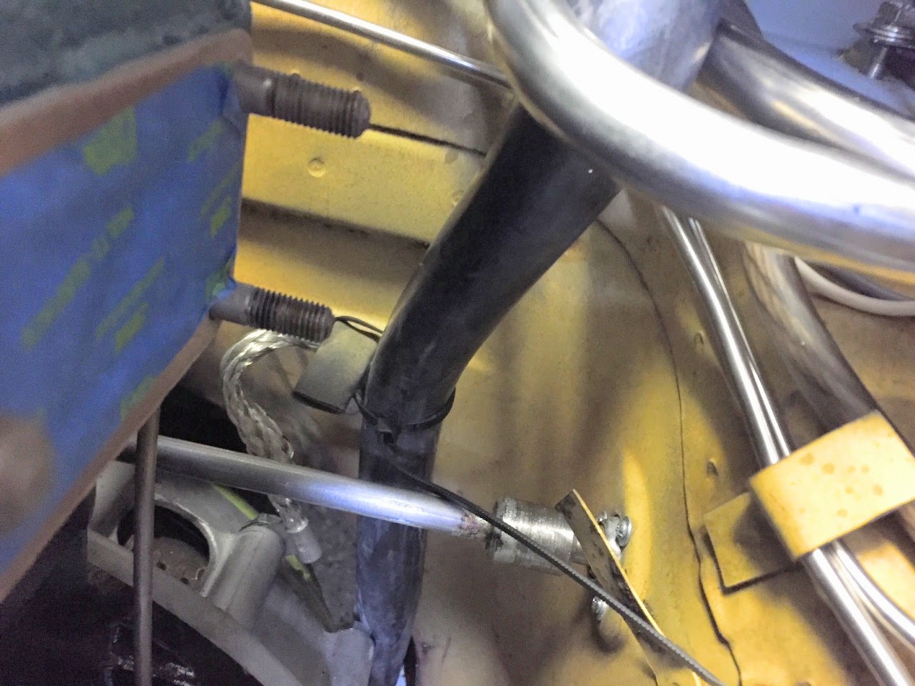
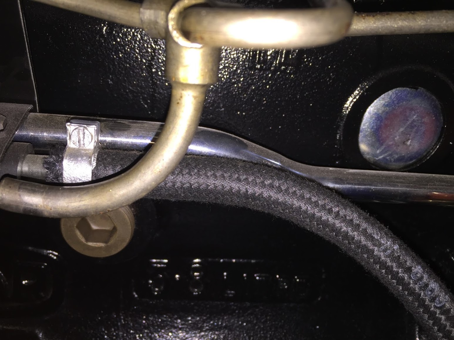
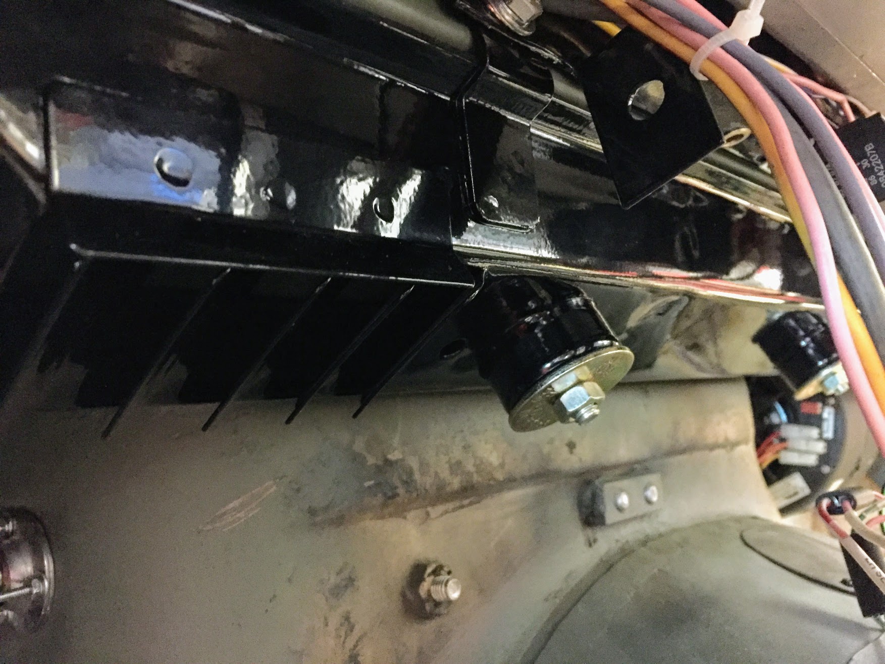
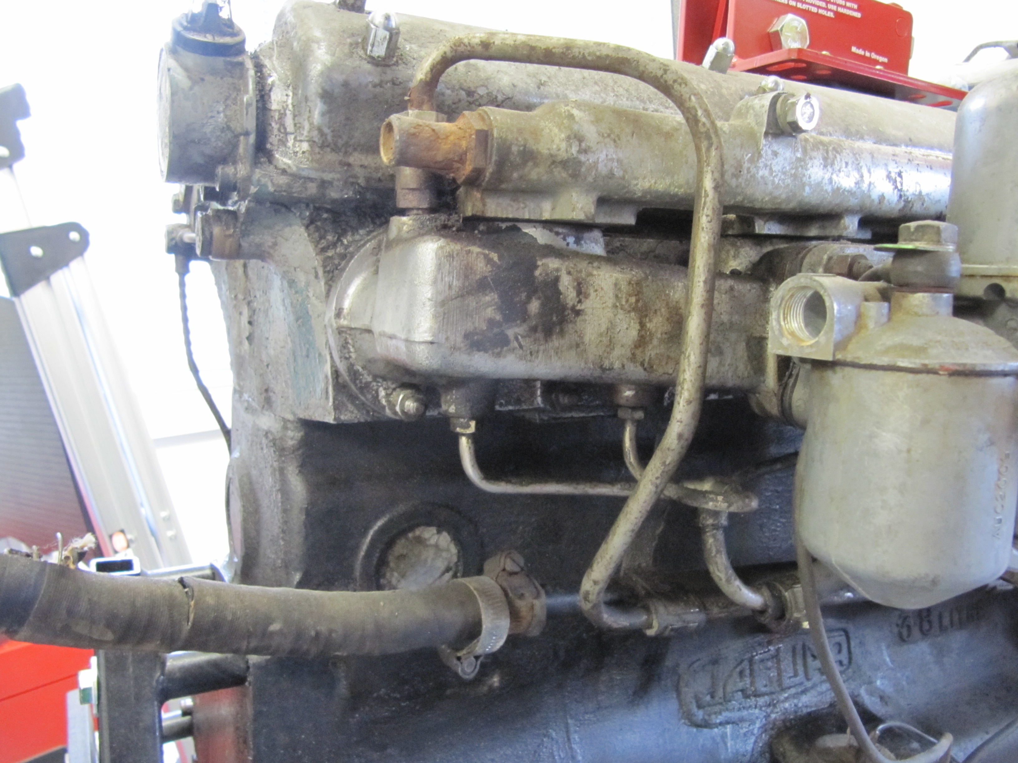
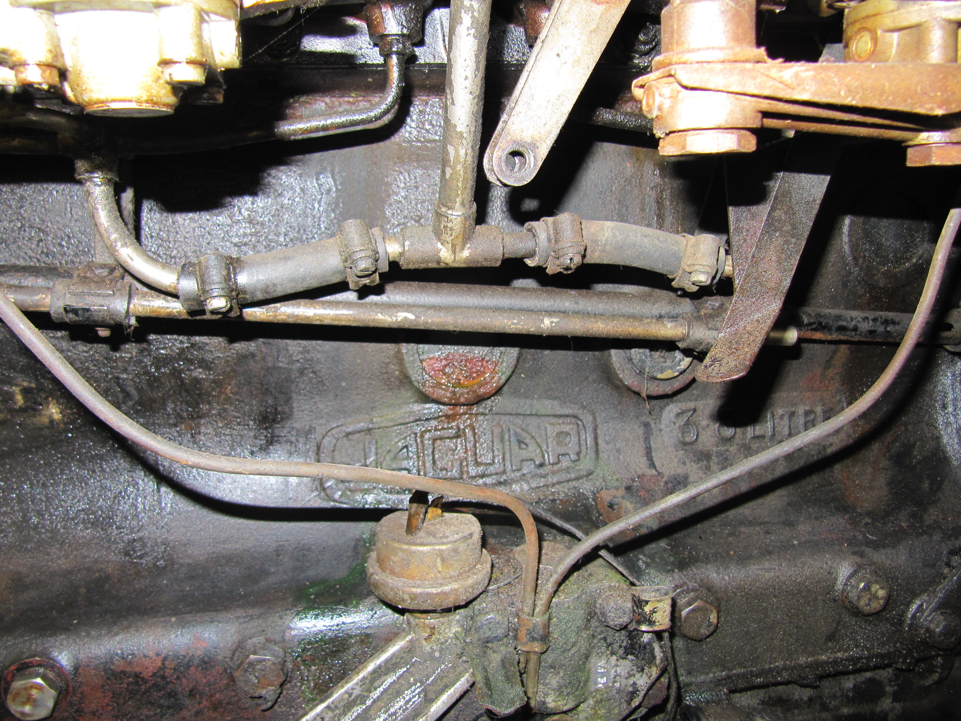
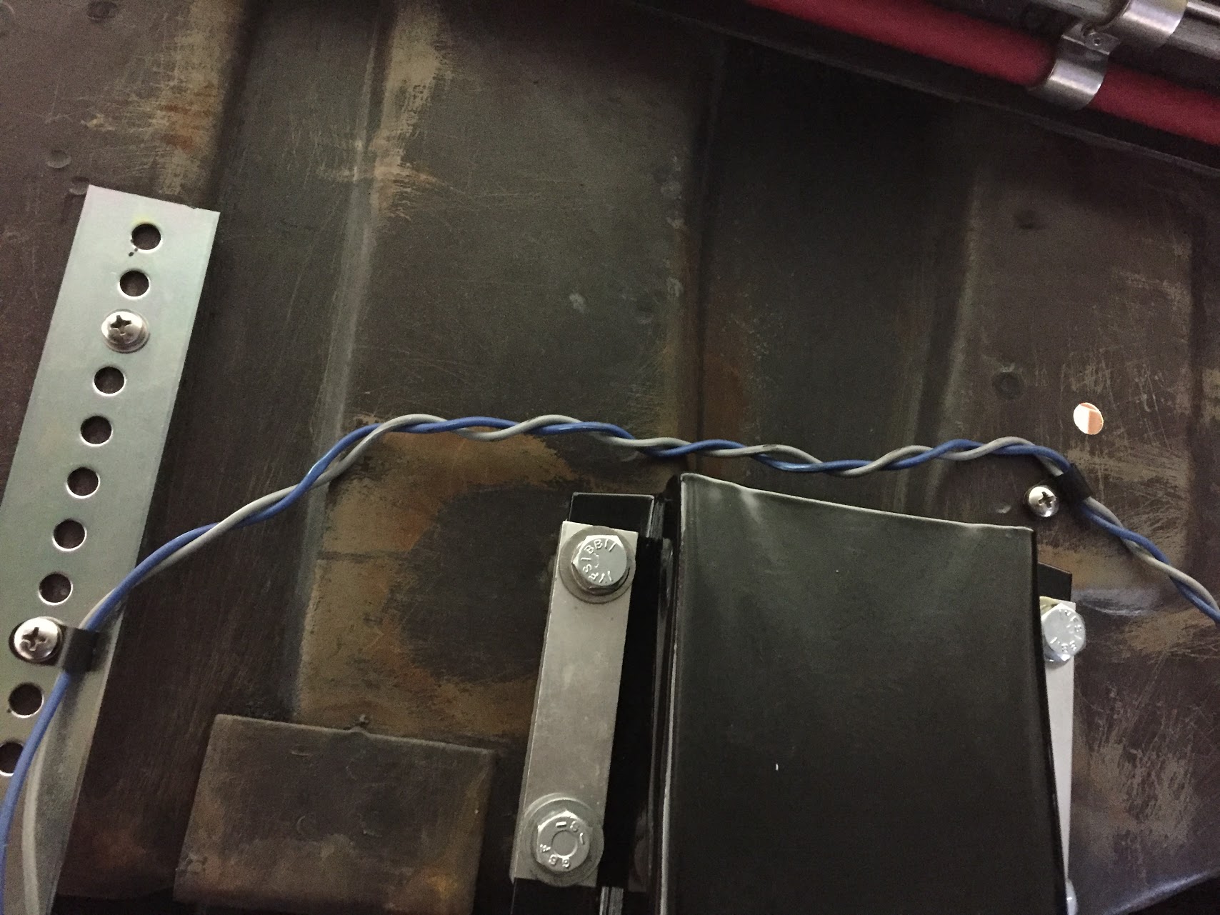
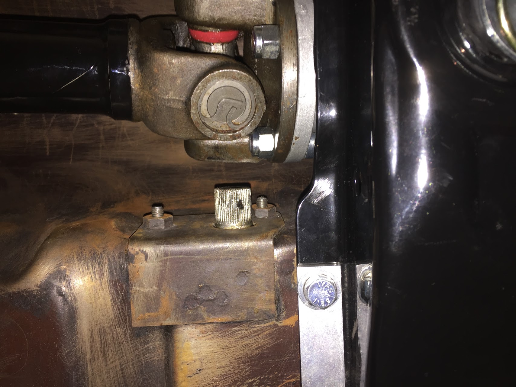
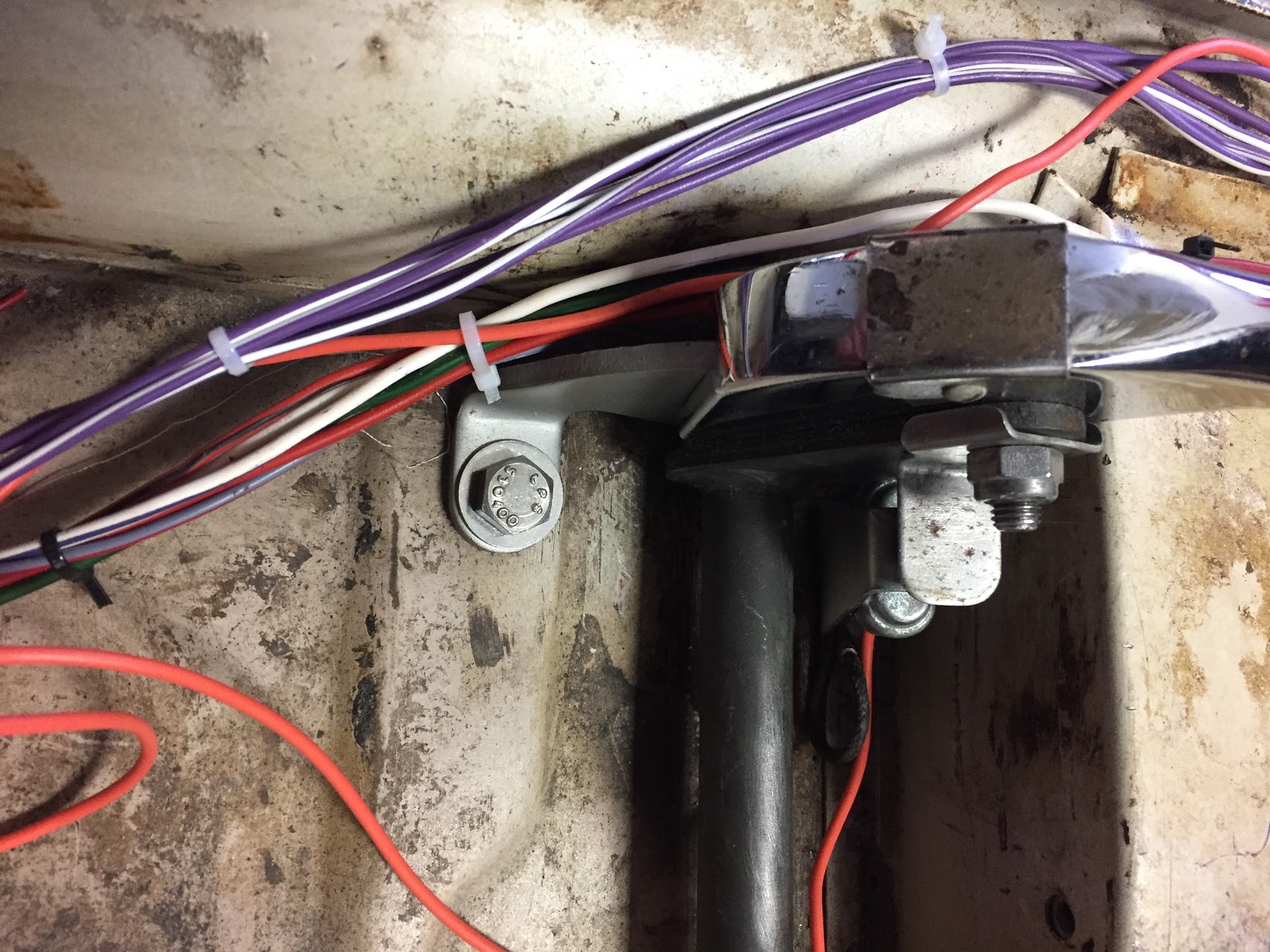
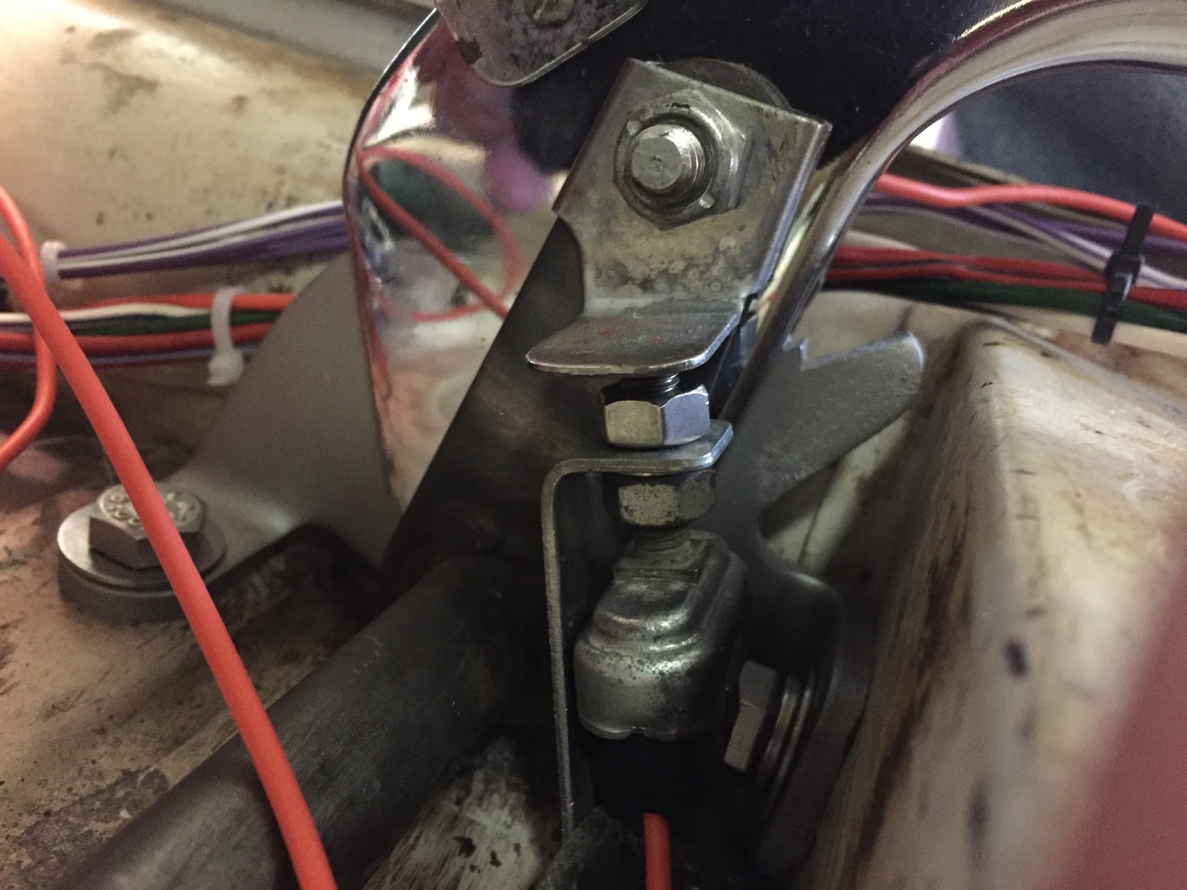
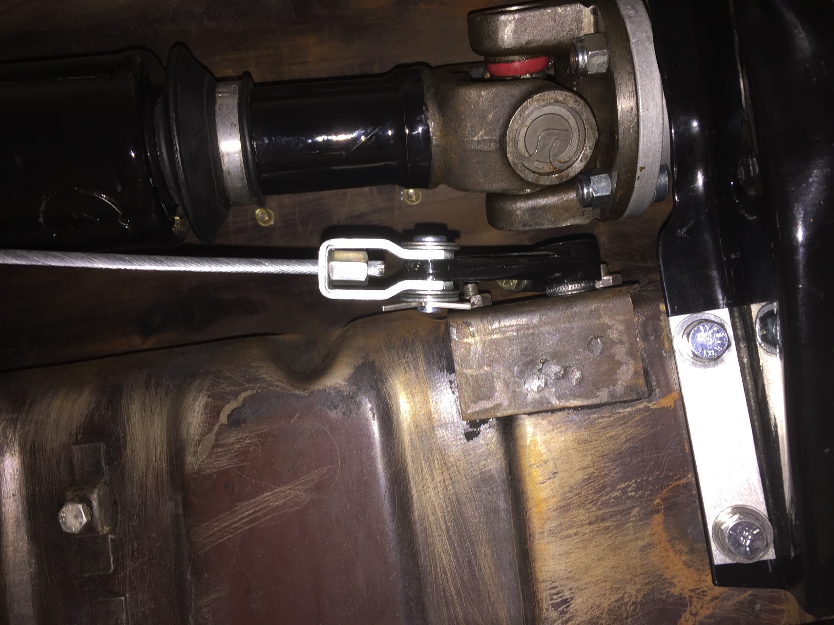
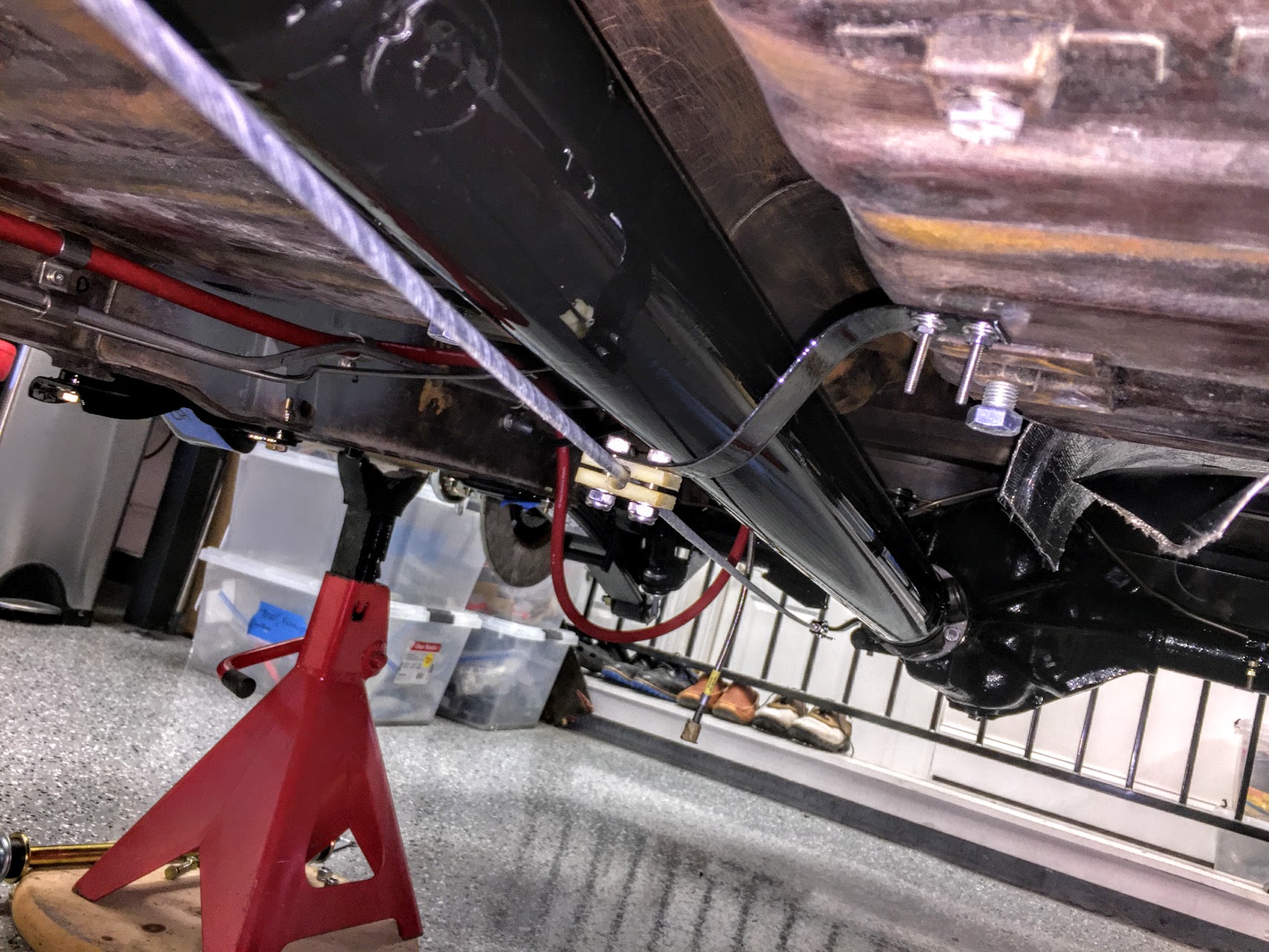
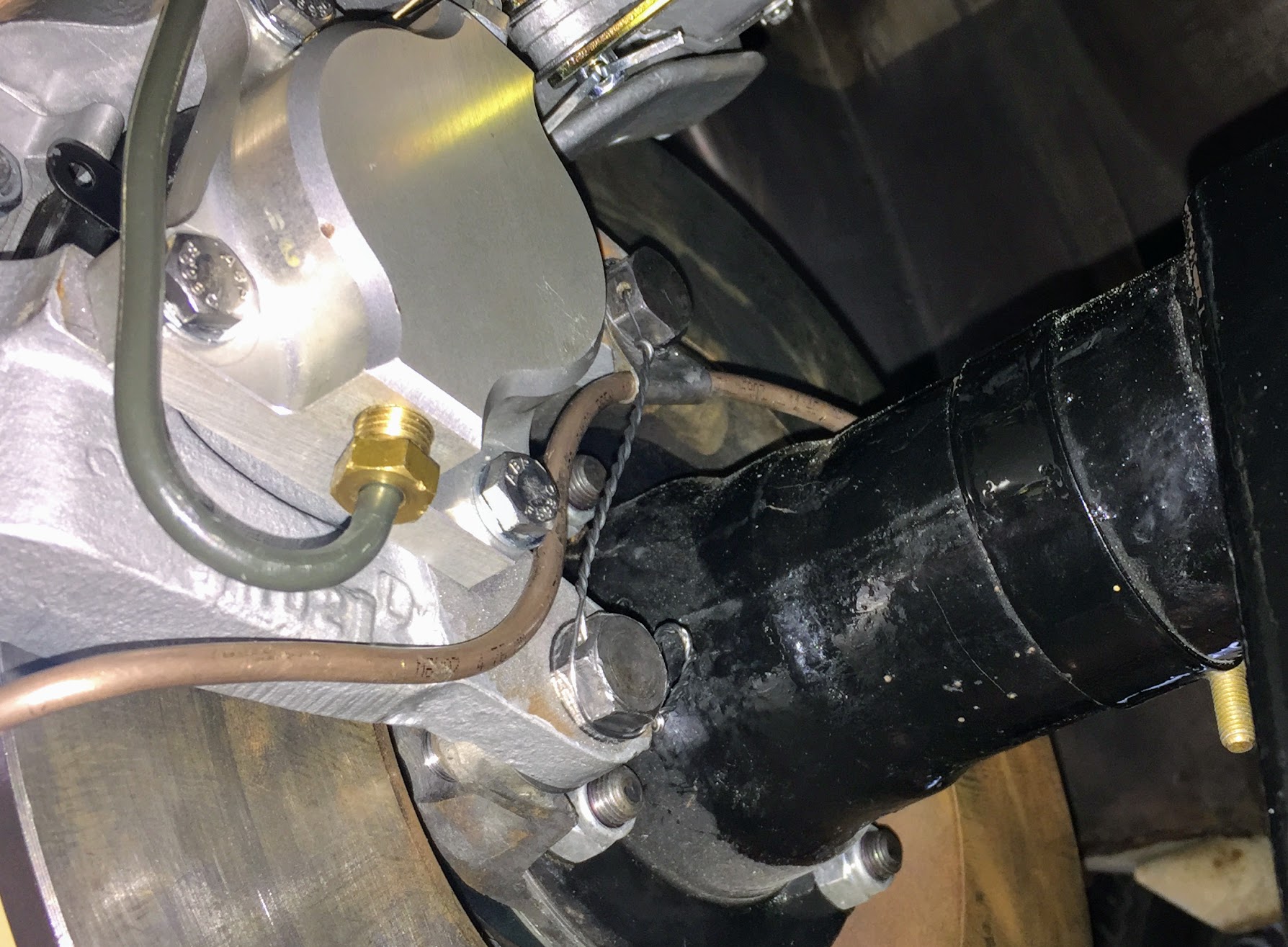
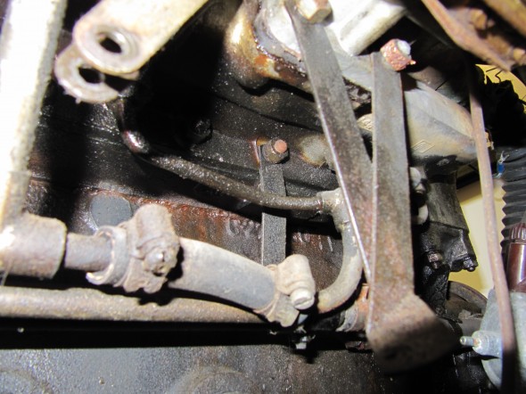
The Front Return Pipe is secured parallel to the RH side of the engine block with brackets mounted to inlet manifold studs ( the third stud from the front of the engine and the third stud from the rear). The Brake Servo Vacuum Pipe is paired with the Front Return Pipe held by the same brackets.
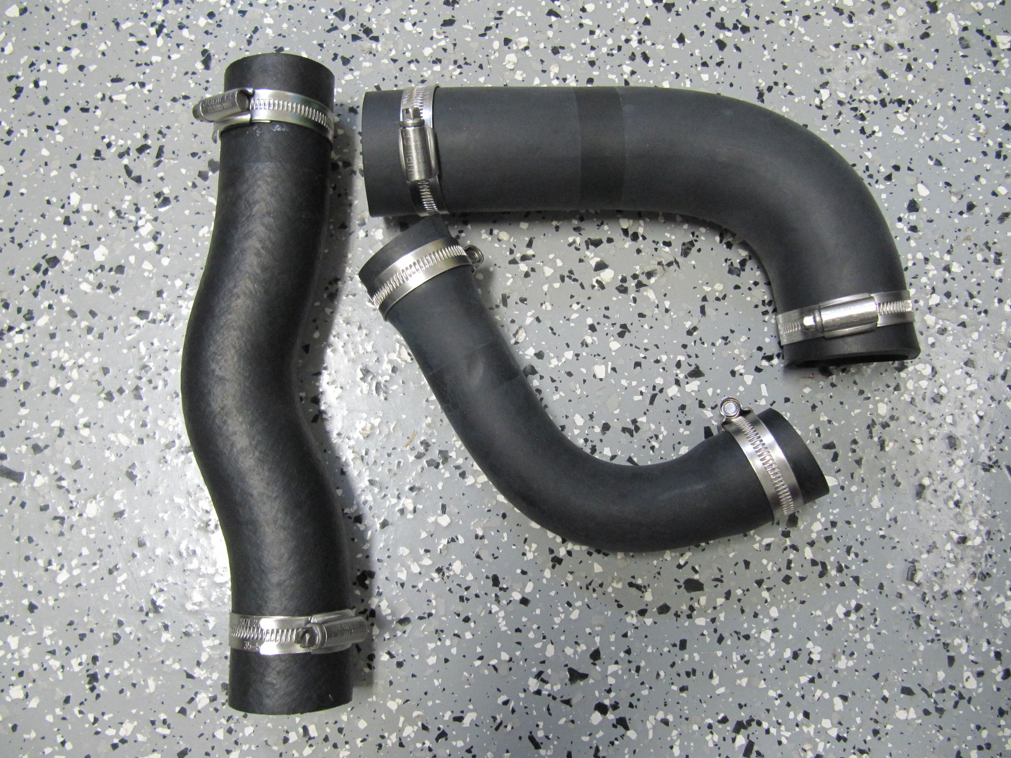
Two identical elbow hoses part C16655 are used to connect the pipes to the heater matrix and water valve assembly. An accordion type hose, part C21961, connects the feed pipe to the adapter at the rear of the inlet manifold. This hose can be seen in the image above.
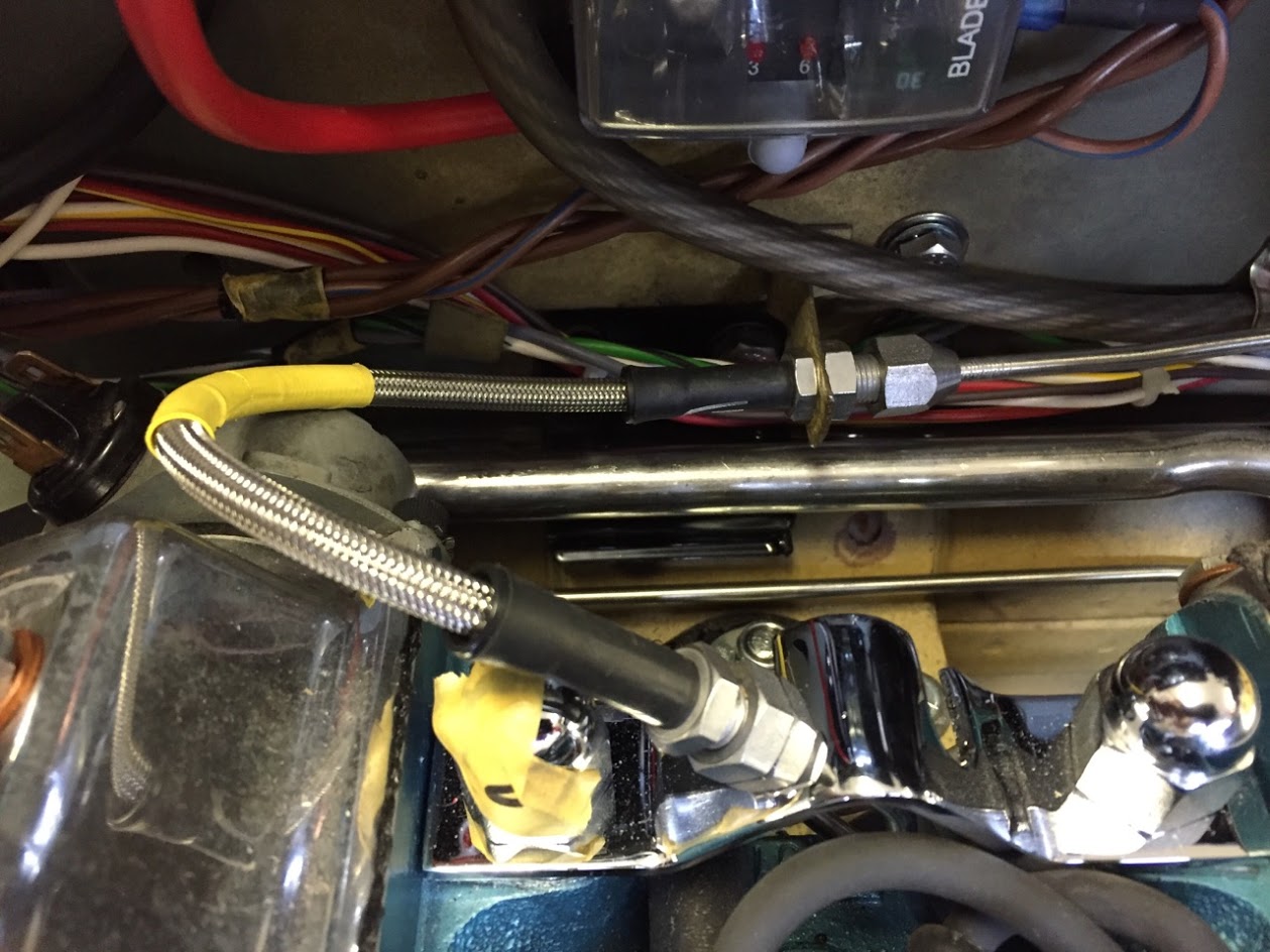
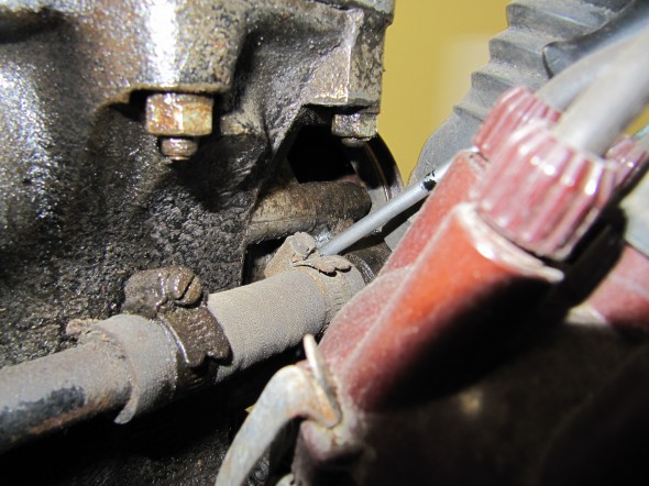
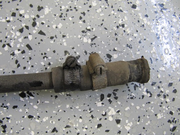
The front return pipe and the rear return pipe are connected with a straight piece of hose, part C14999/3. A shorter straight piece of hose connects the front the front return pipe to the adaptor on the water pump. All of the hoses are secure to the hard pipes with Cheney clamps that were sourced from XKs Unlimited.
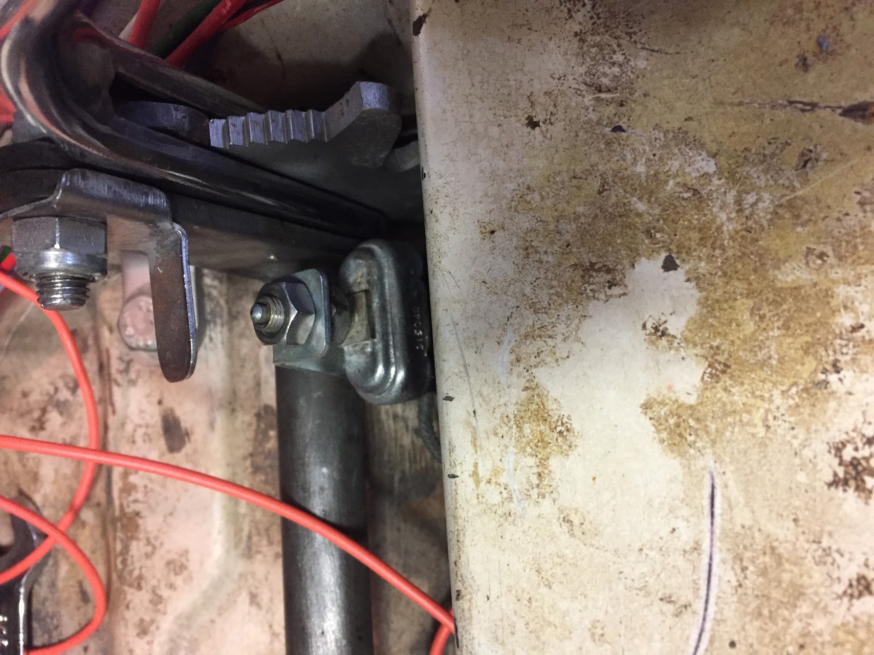
The offset in the Front Return Pipe is to the front of the car. I removed the two Brackets On Studs of Inlet Manifold by loosening the two 3/8″ – 24 stud nuts. At the front of the pipe I disconnected the hose 9/16″ hose clamp and pulled the pipe away with the 3 1/2″ Hose, From Front Return Pipe to Adaptor on Water Pump. The hose uses two 9/16″ clamps to connect the hose to the pipe and to the adaptor. The Hose From Rear Return Pipe to Front Return Pipe is 8 1/2″ long also secured with two 9/16″ clamps. For ease of removal, I disconnected the Vacuum Pipe Assembly from the top of the Inlet Manifold, and could then lift away both pipes and brackets from the engine block.
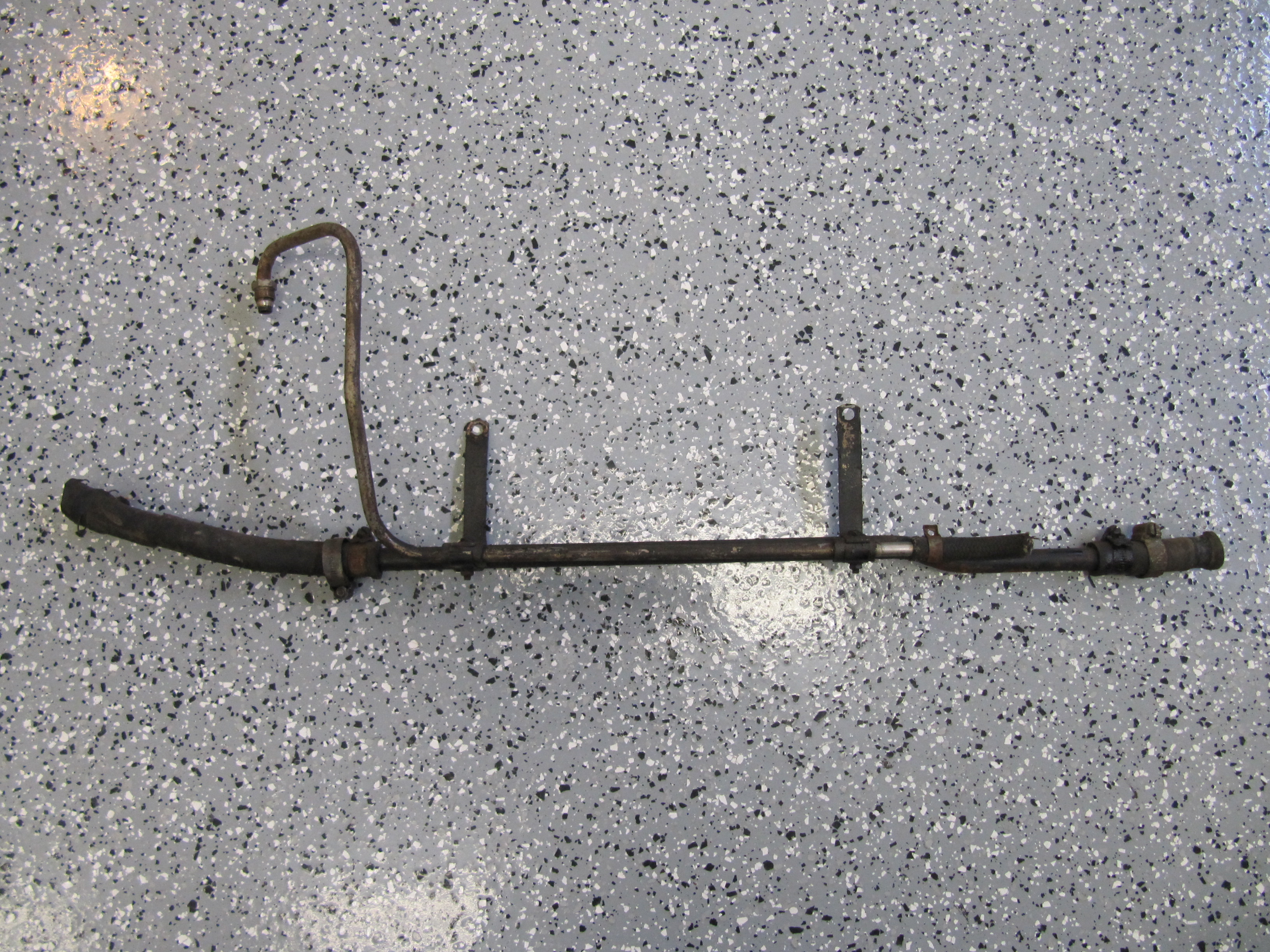
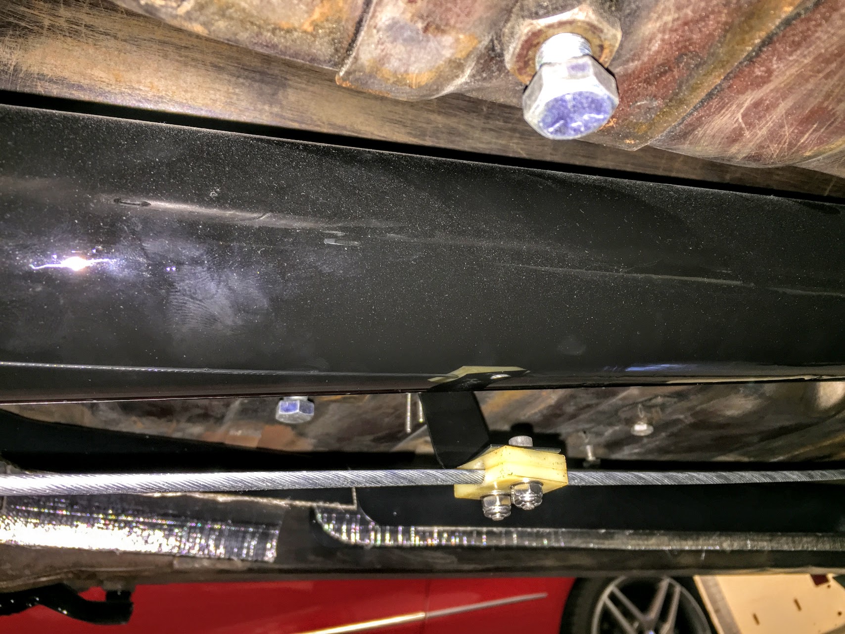
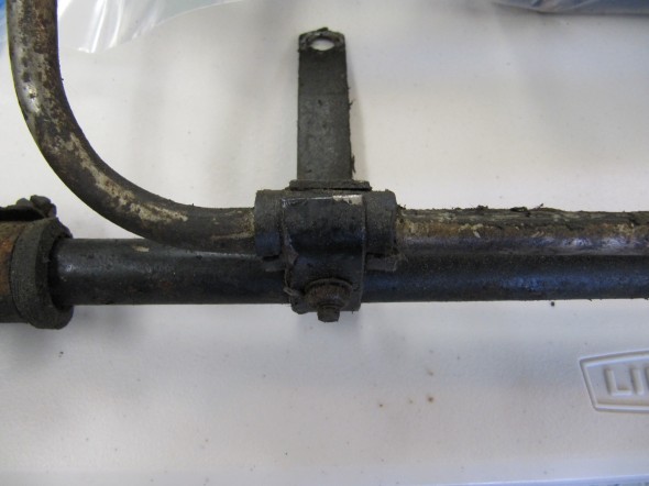
The Front Return Pipe and the Vacuum Pipe were then separated by loosening each of the mounting brackets components held together with a hex head #10 – 32 x 1″ machine screws, nuts and shakeproof washers. Two 1″ long pieces of rubber hose (slit length wise) wrapped around the vacuum hose to keep the two pipes from rattling against each other.

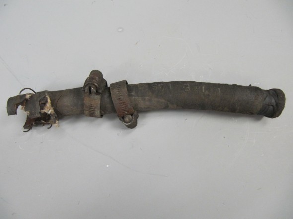
Front Return Pipe at Side Of Cylinder Block – Rear Hose
Front Pipe Hose
Front Pipe Hose

Front Return Pipe
Pipe Brackets
Front Return Pipe
Front Heater Return

Hose from Front
Hose from Rear
Front Return Pipe Hoses
Brackets prepared for painting:
Brackets-on-Studs-of-Inlet-Manifold-for-Fixing-of-Heater-and-Servo-Pipes Ready to Paint
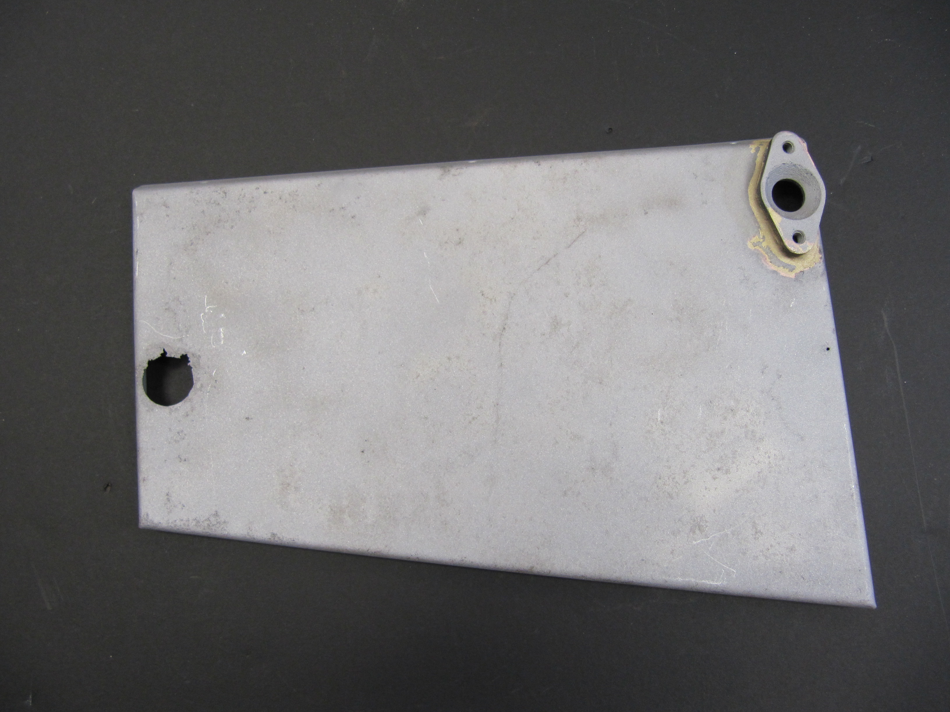
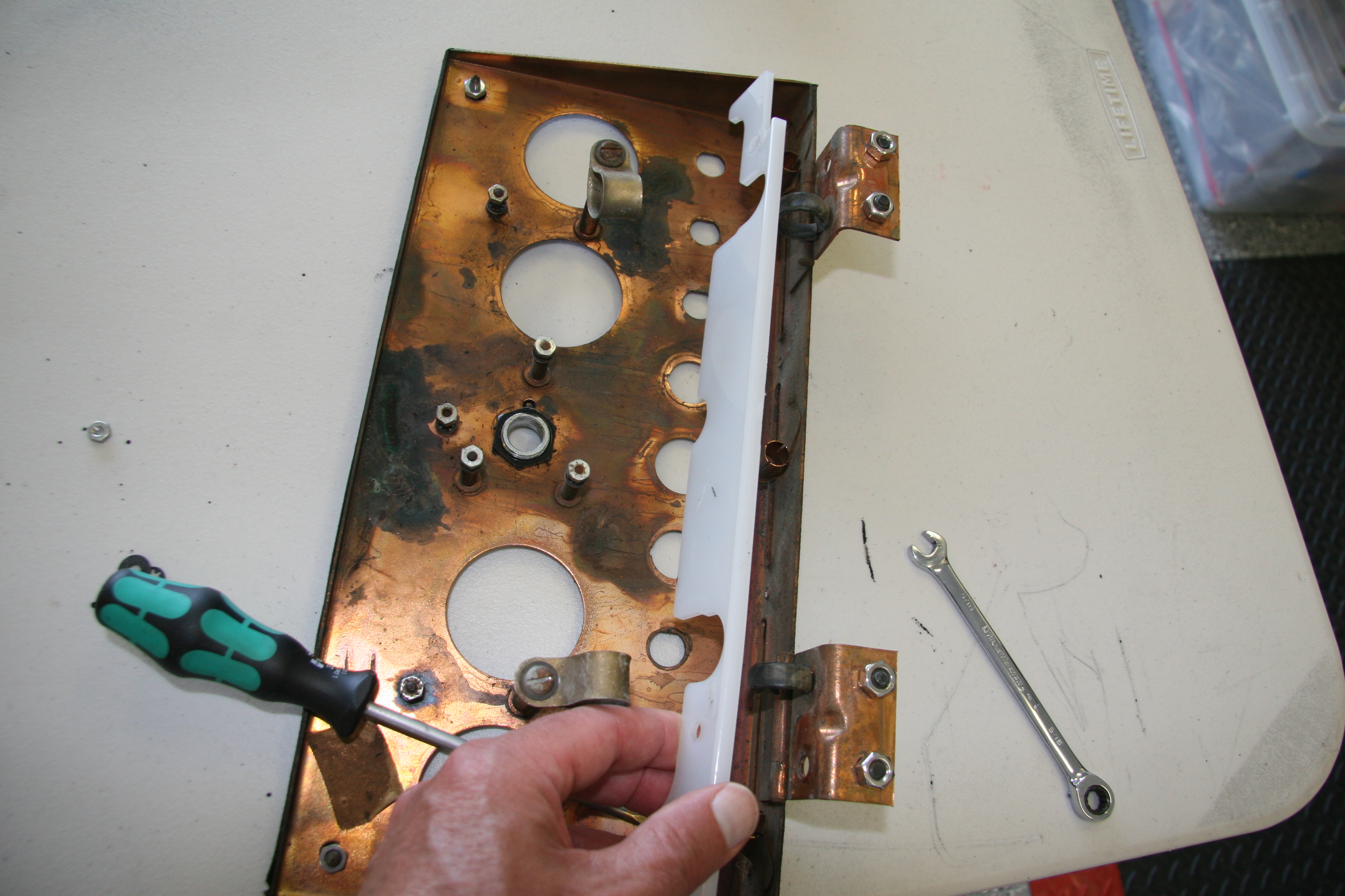
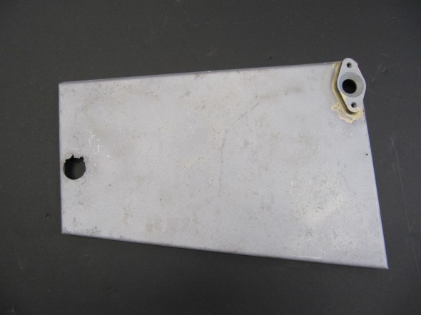
Cover Plate Over Pedal Mounting Cut-out on Centre Dash
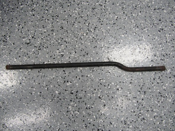
I am replacing the Front Heater water return pipe with a new stainless pipe: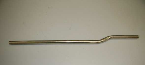
I also purchased a new foam rubber seal from the the heater to the dash volute.
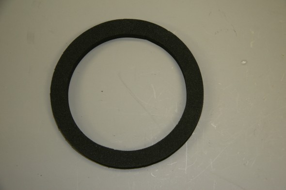
Rubber Seal from heater to Dash Volute
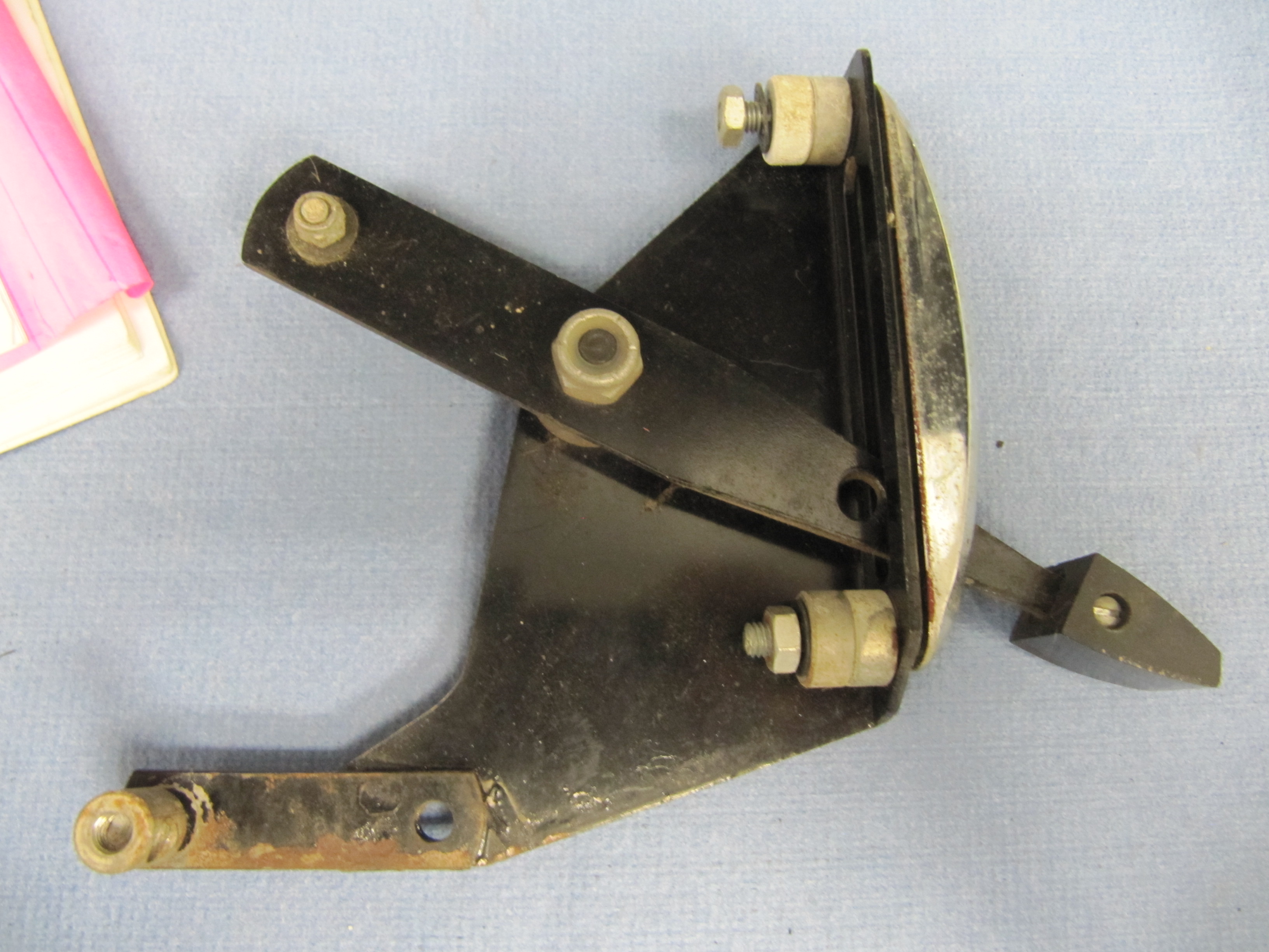
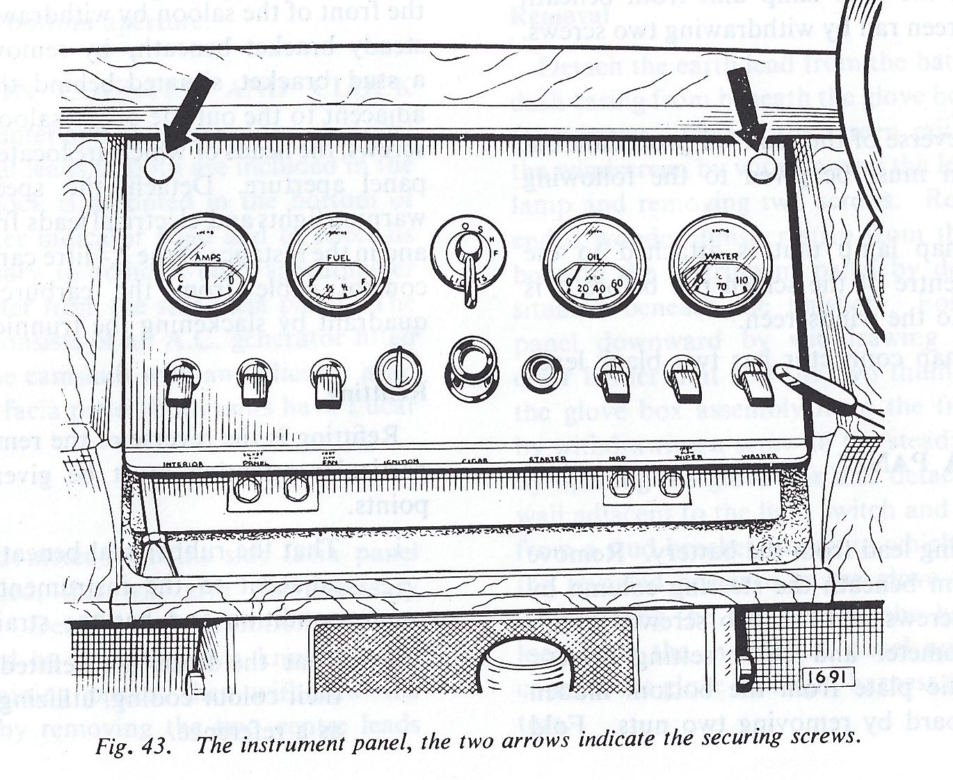
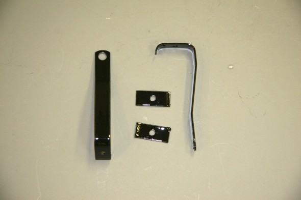
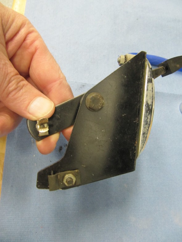
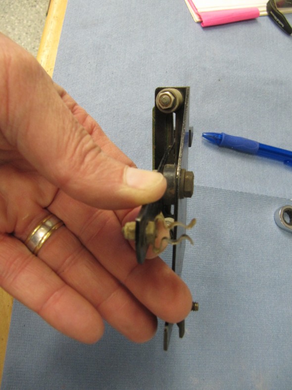
Heater Control Lever Assemblies
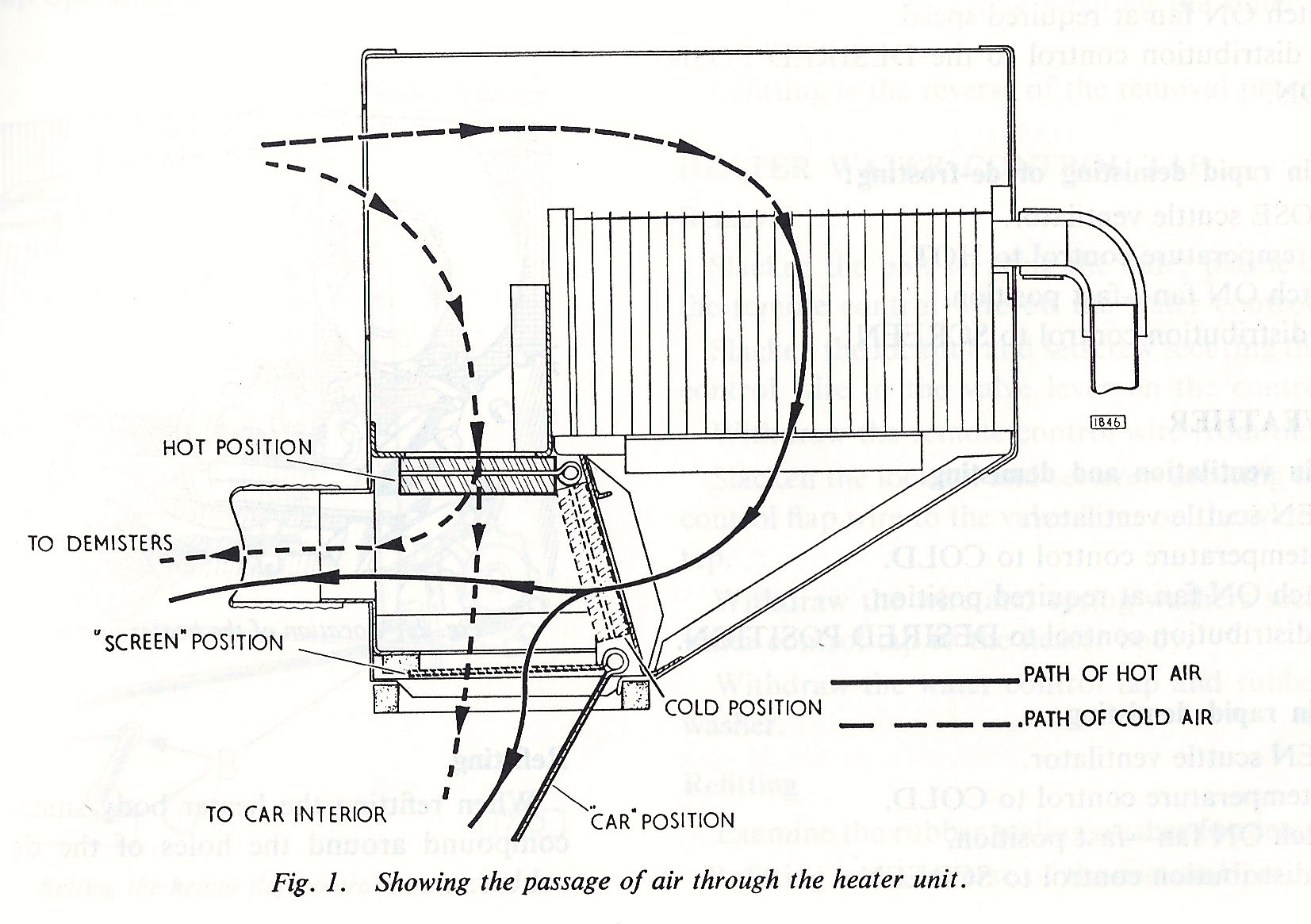
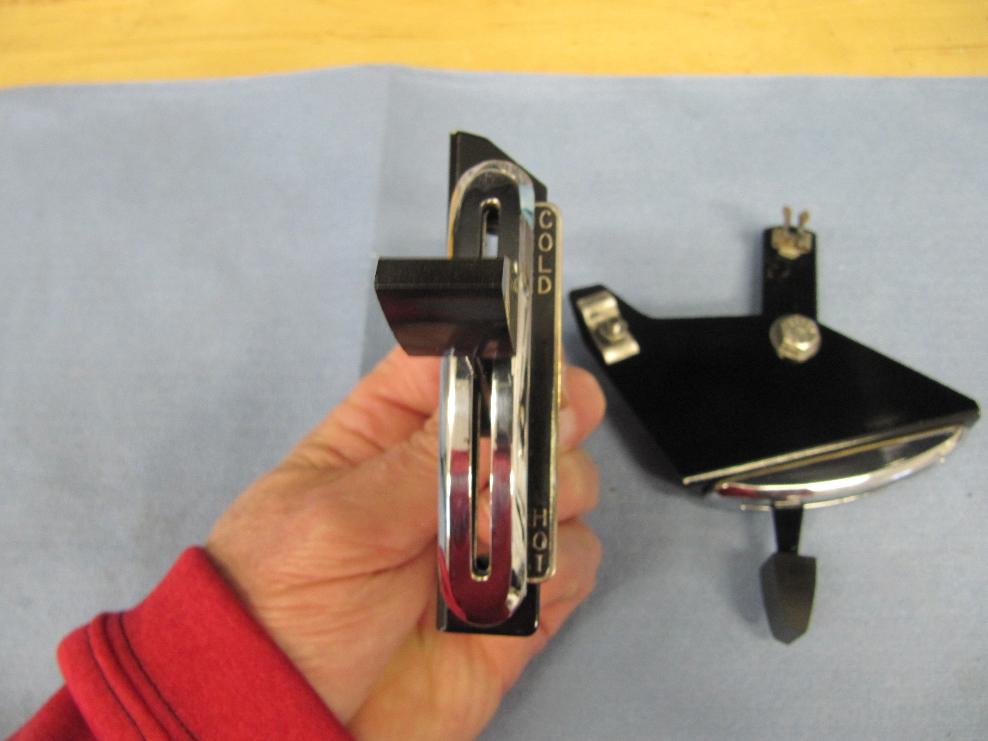
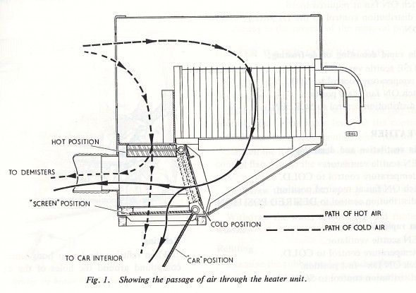
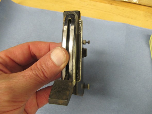
Two levers mounted in the central control panel in the console control the temperature and distribution of air into the cockpit. The temperature control – marked “Hot” and “Cold”situated below the instrument panel operates a valve which controls the flow of air through the heater. When the control is placed in the “Cold” position the supply of air from the heating element is completely cut off so that cold air can be admitted for ventilating the car in hot weather. Placed in the “Hot” position the maximum amount of air passes through the heating element. By placing the control in intermediate positions varying degrees of heat can be obtained.
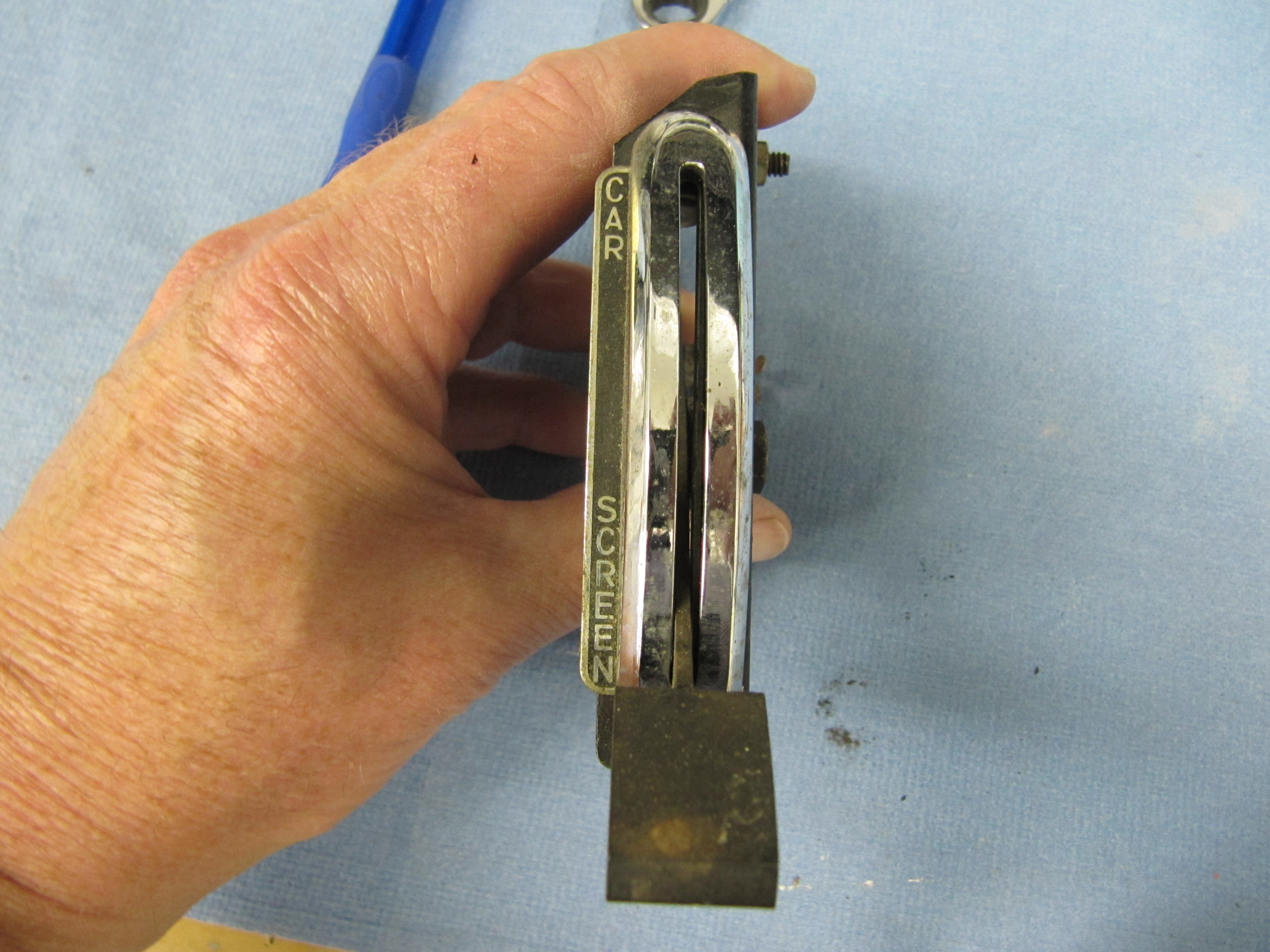
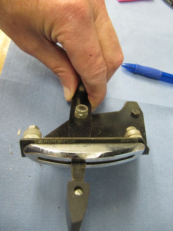
The distribution control – marked “Car-Screen” controls the proportion of air directed to the windscreen or the interior of the car. Placed in the fully upward position the maximum amount of air will be admitted into the car interior. Placed in the fully downward position the maximum amount of air is directed to the windscreen for rapid demisting or defrosting. By placing the contra in intermediate positions varying proportions of air can be directed into the car interior and to the windscreen.
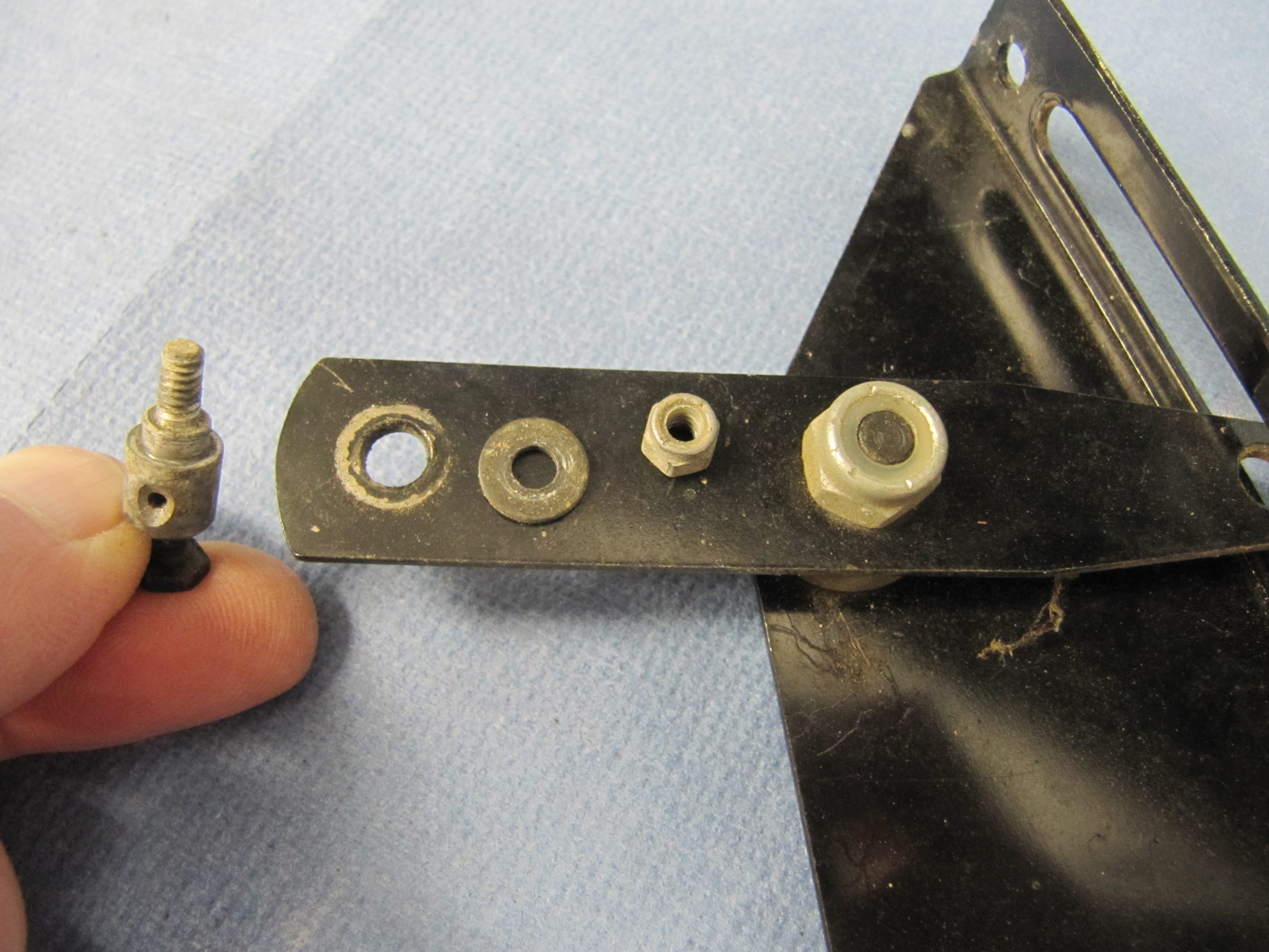
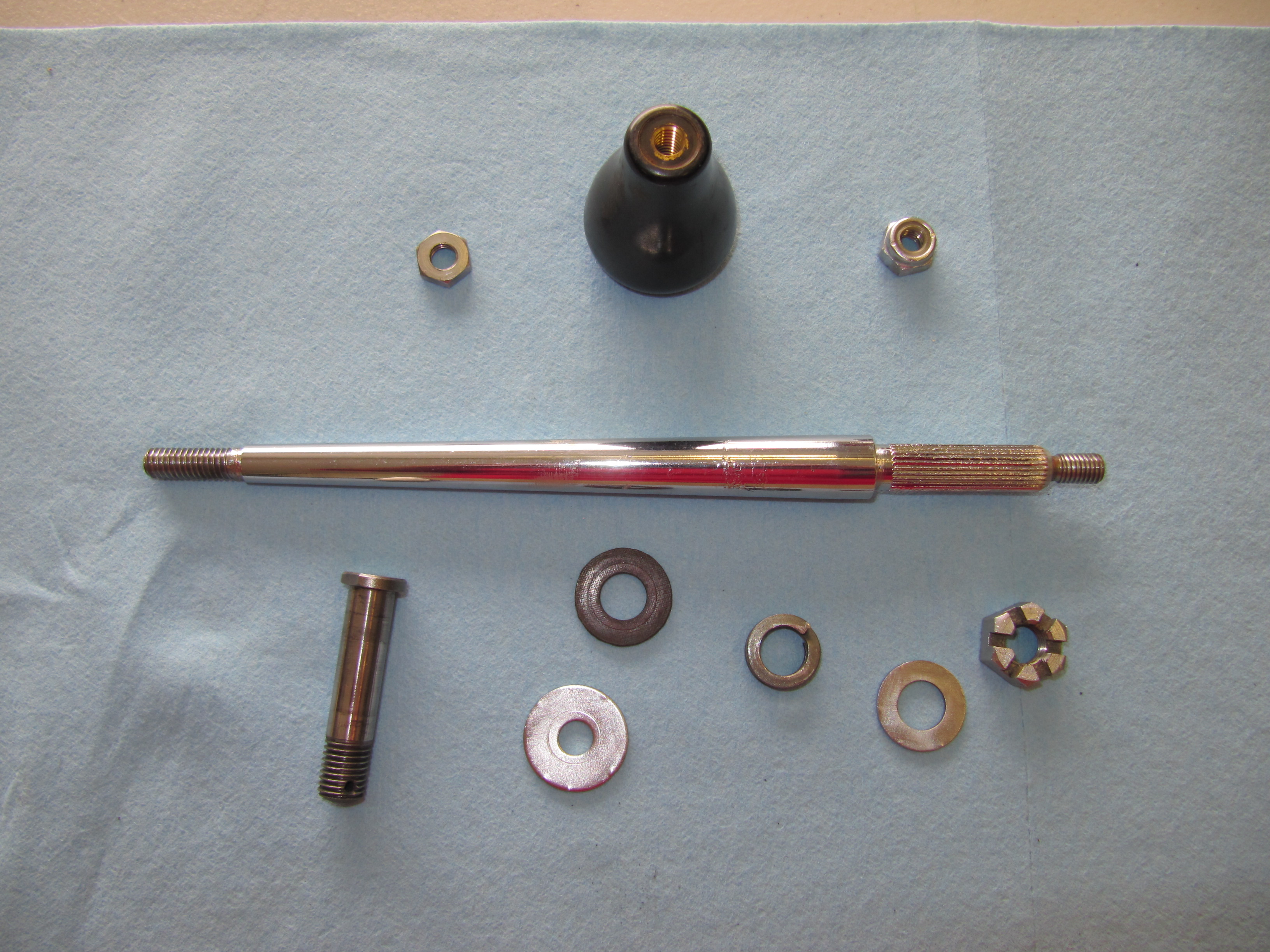
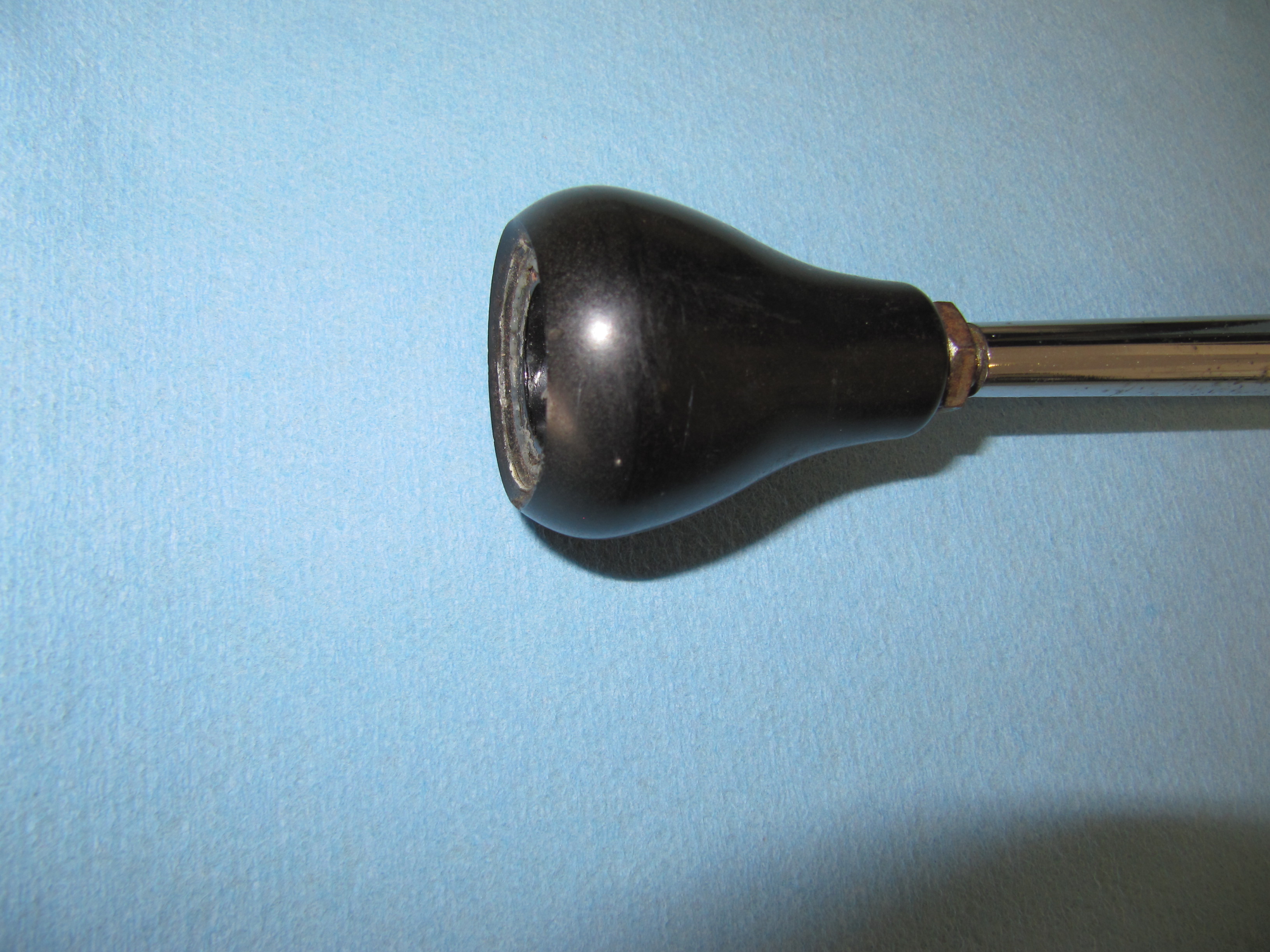
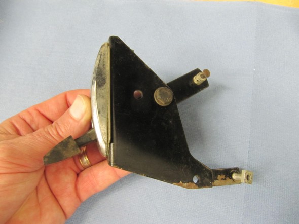
The lever controls consist of the mounting brackets and control arms with chrome bezels and inscribed instructional plates. A plastic knob is screwed into each control arm. Cable attachment hardware and two distance pieces for each chrome bezel mounting post is located on each control arm and bracket. Both assemblies wherein reasonably good condition. I will try to replace the inscribed plates if I can locate a source. I cleaned both assemblies, polished the chrome, lever knob and instructional plates and primed and painted each.
Temperature Control Lever
Temp Control Lever
Temp Control Lever
Temp Control Lever

Temp Control Lever
Distribution Control Lever

Distribution Control Lever
Distribution Lever
Distribution Lever
Distribution Lever
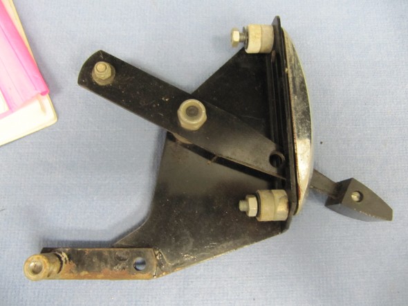
Temperature and Air Distribution Levers after Renewal

Temperature and Air Distribution Levers
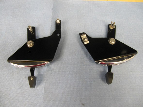
Temperature and Air Distribution Levers
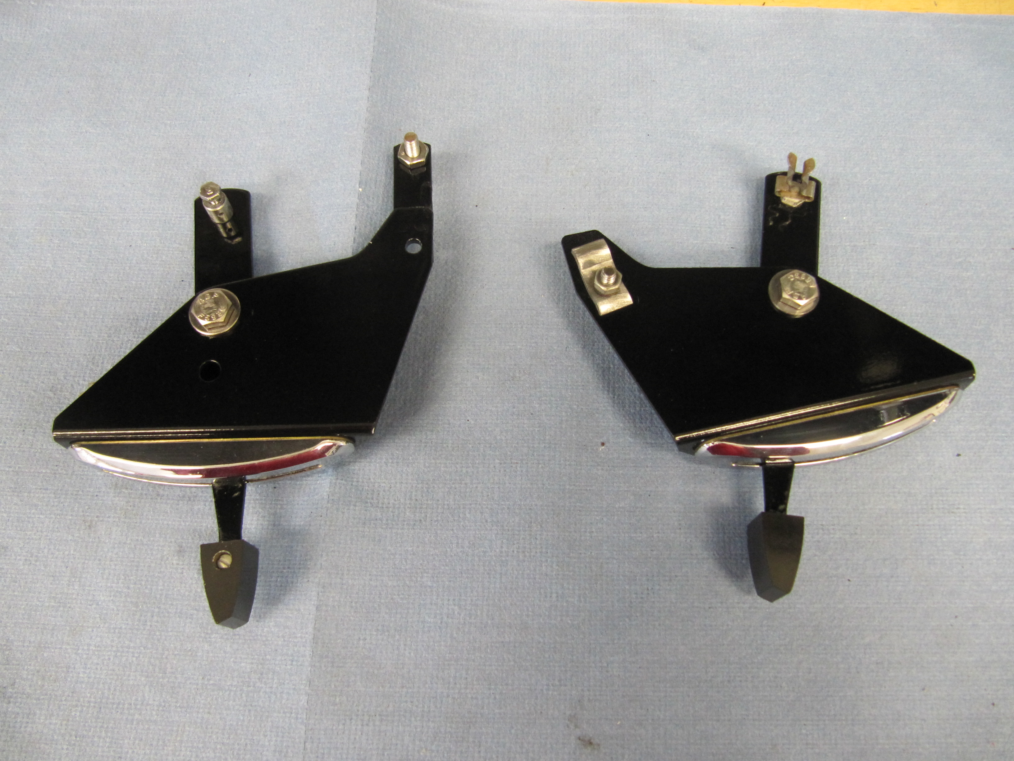
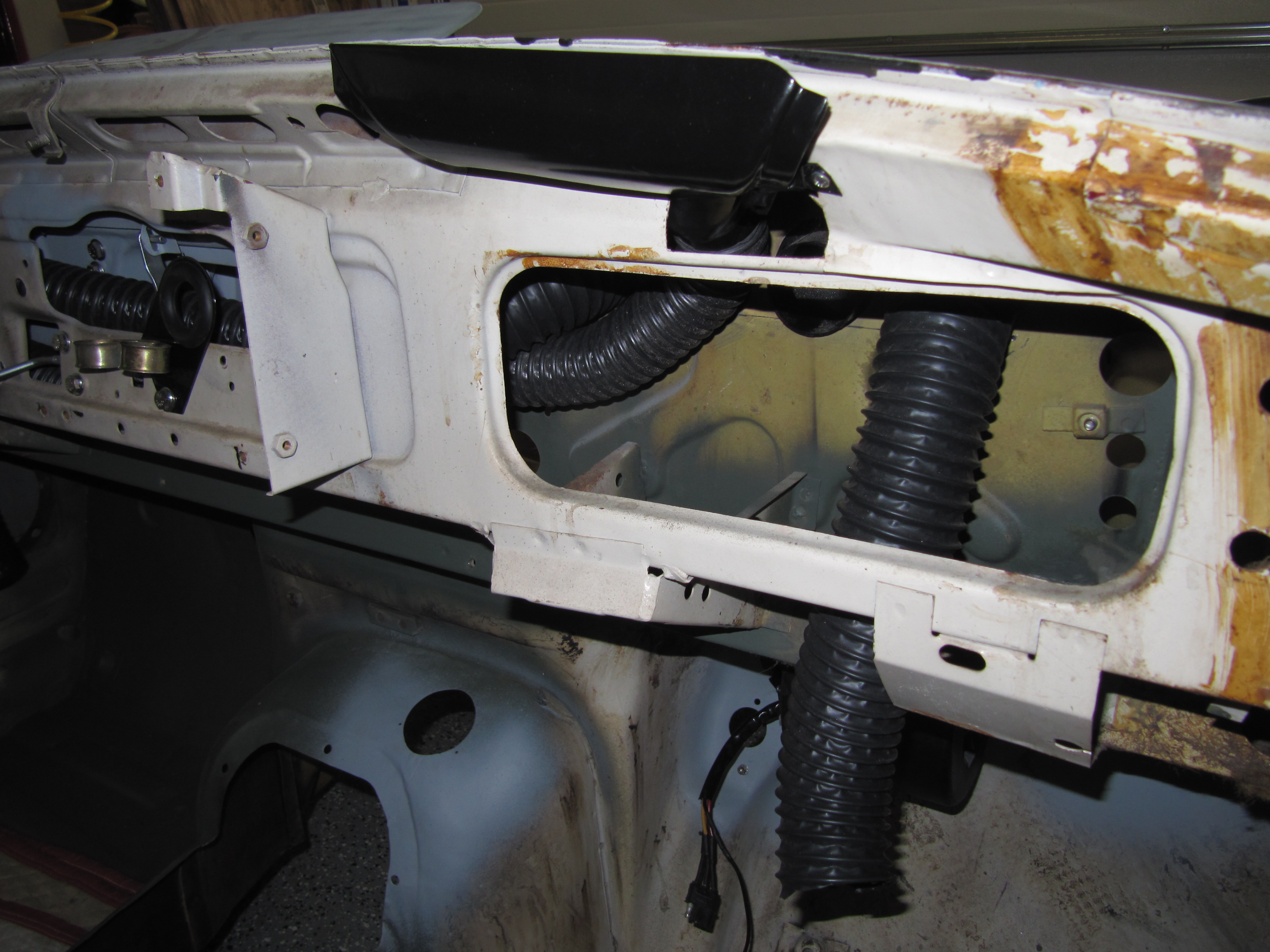
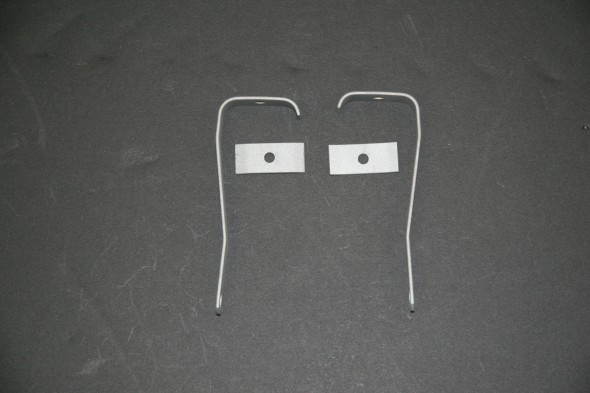
Windscreen Demister Nozzles
Each of the demister nozzles is attached to the scuttle with two #6 x 1/2″ pan head screws. Flexible hose connects each nozzle to rubber elbows in the firewall that access the heater aperture in the scuttle. Each nozzle was primed and painted gloss black.
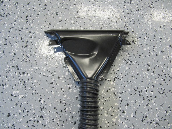
RH Demister Nozzle with Hose

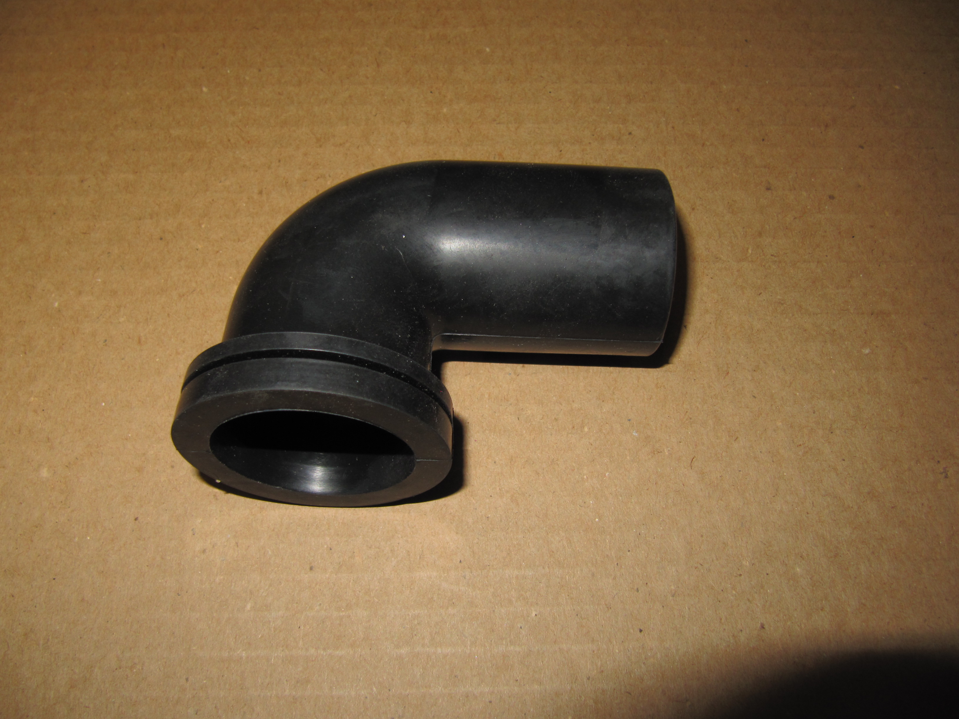
Rubber Elbow
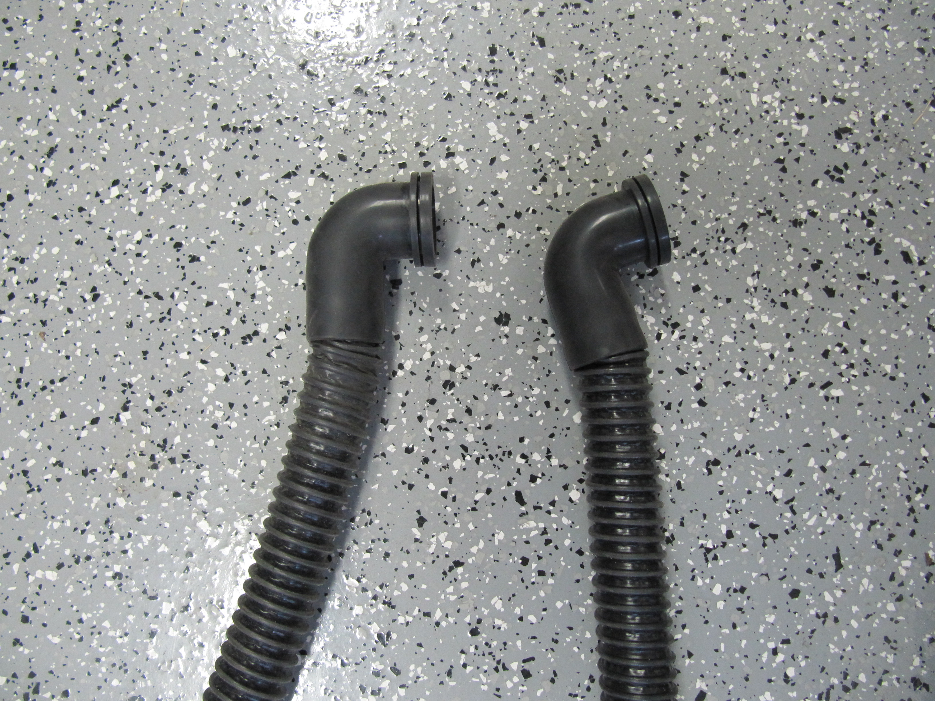
The hose fits inside the rubber elbow. It is a very tight fit. I boiled the elbows in water to make them more pliable and then forced the hose inside. To open the passage and remove any hose restriction I pushed a broomstick up the hose to the elbow.
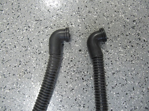
Hoses Installed in Elbows
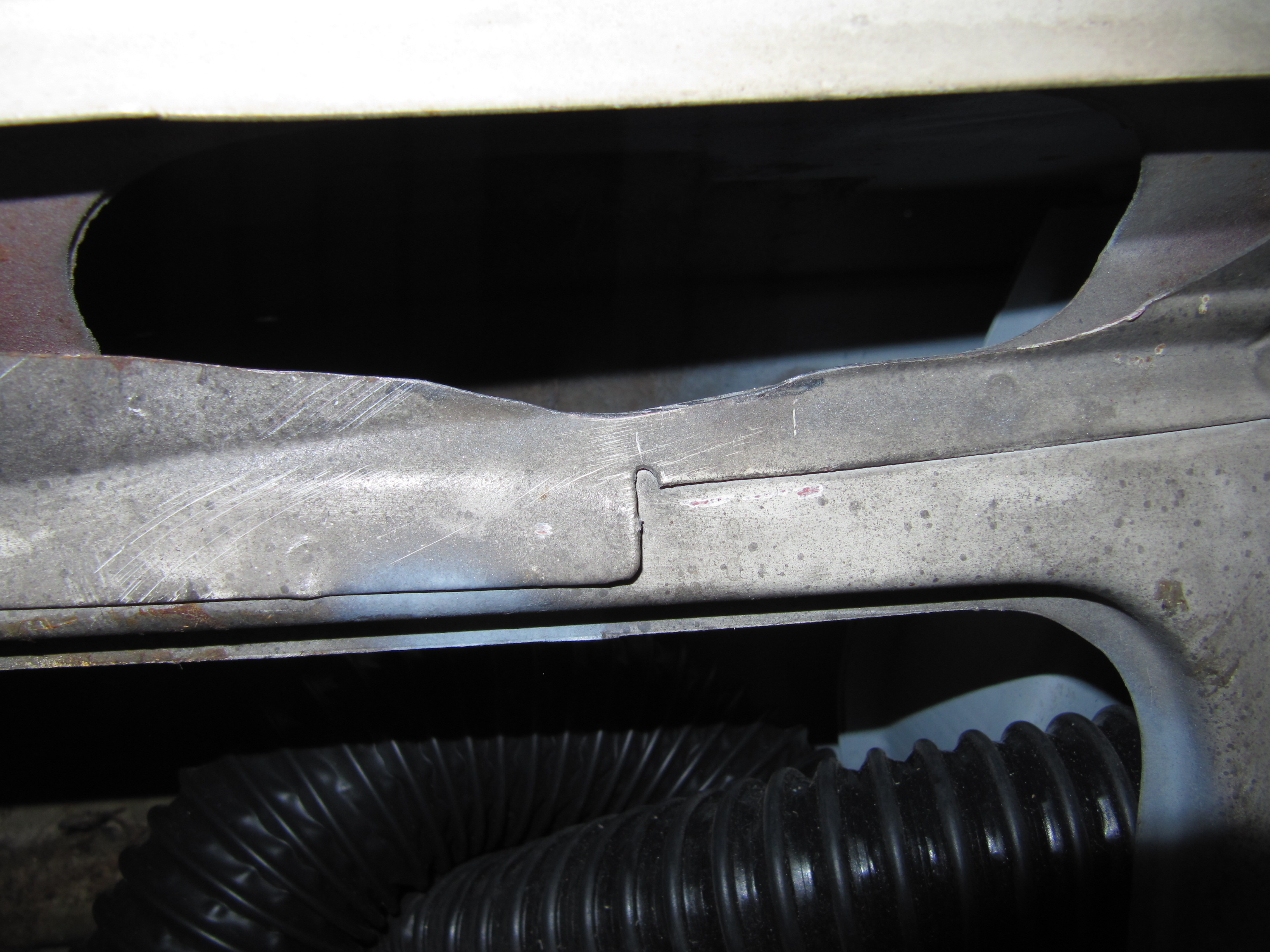
While the RH Demister Nozzle fit into the bodywork quite easily the LH side was very tight so I opened up the sheet metal with a dremel to improve access.
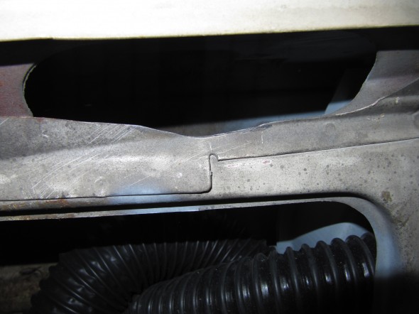
Tight Fit Modification
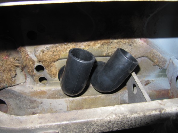
Rubber Elbows in Firewall

RH Demister Installed