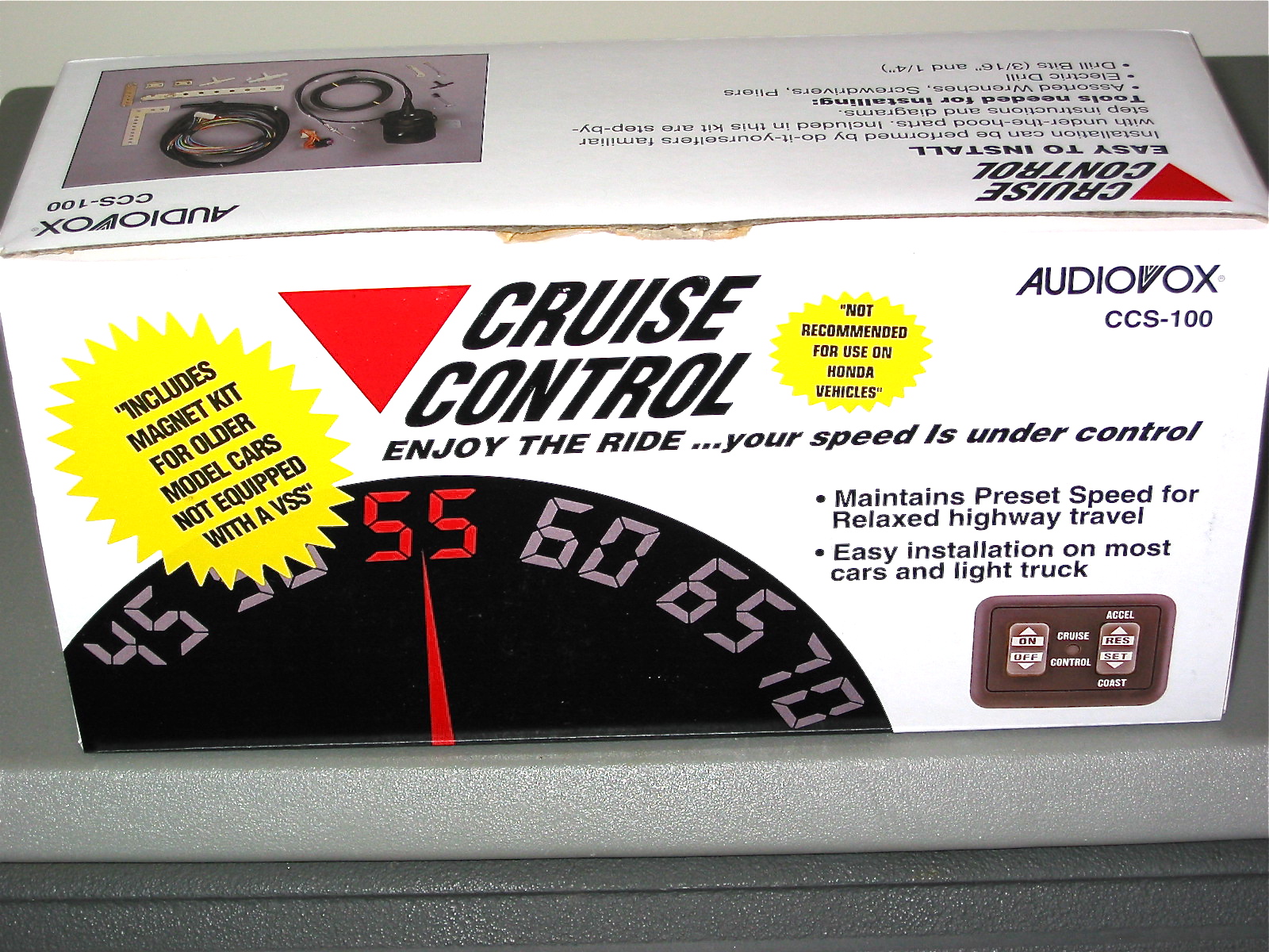
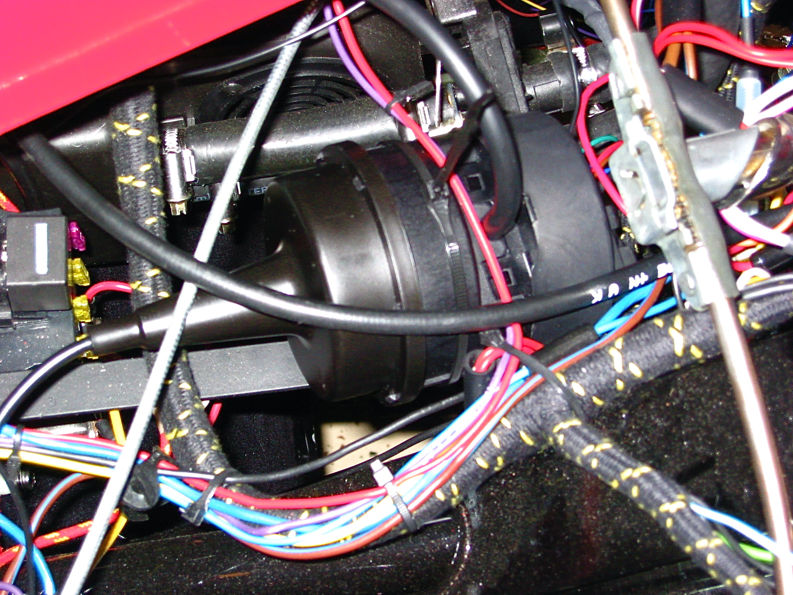
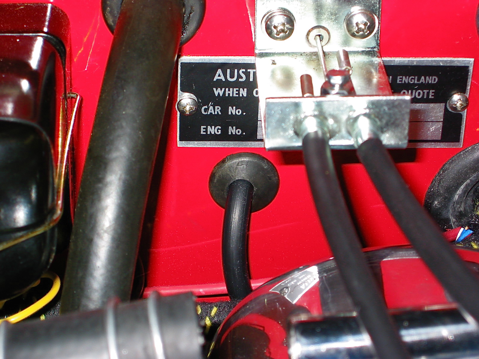
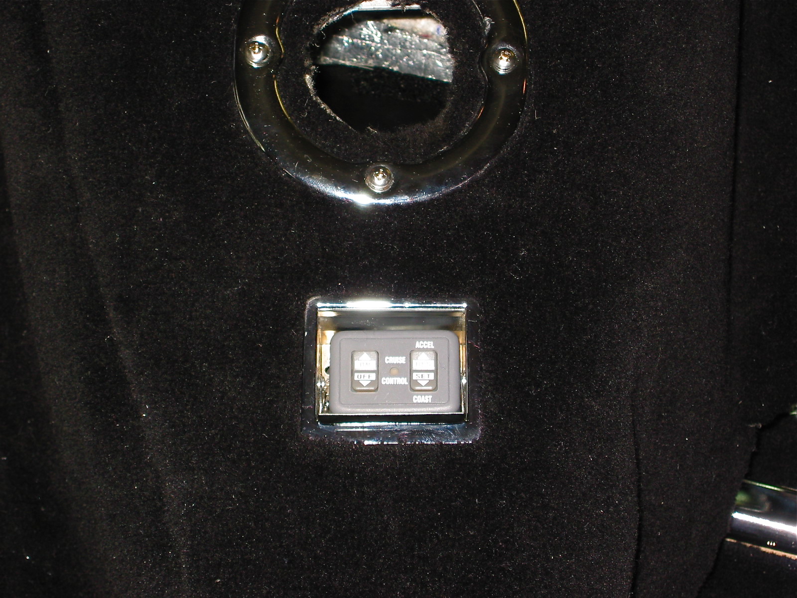
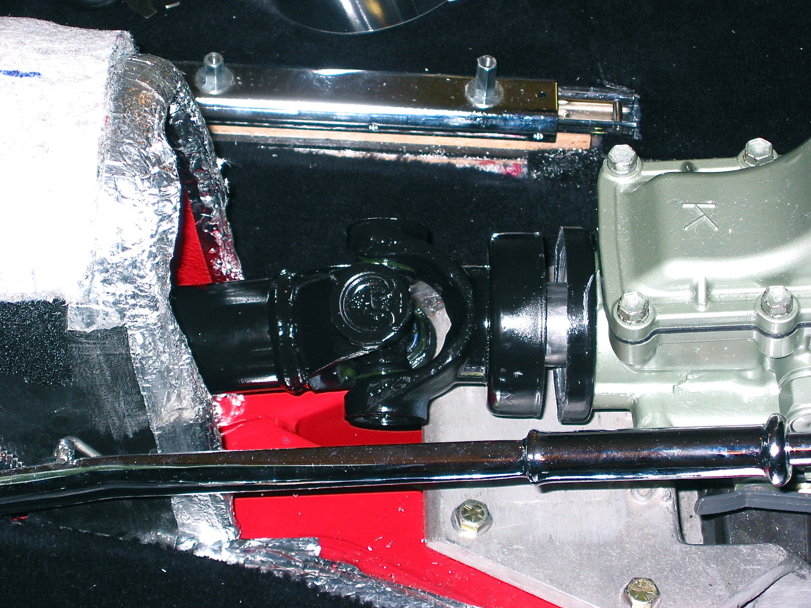
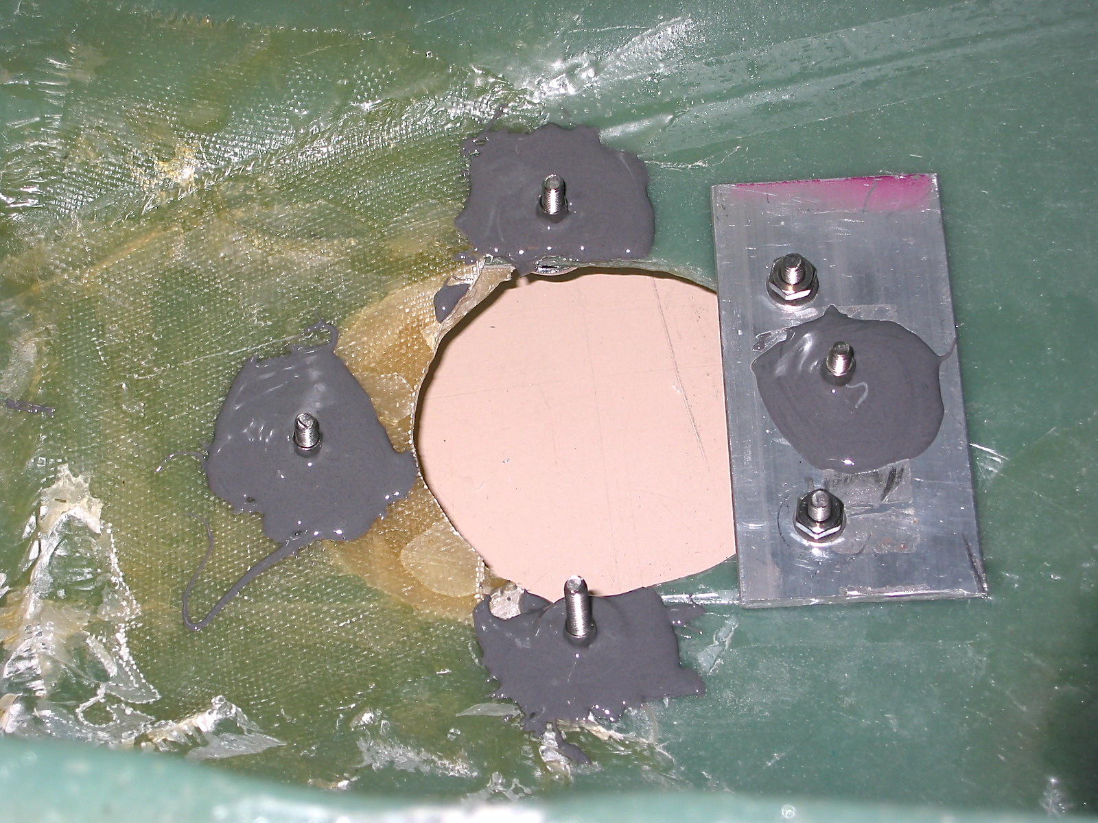
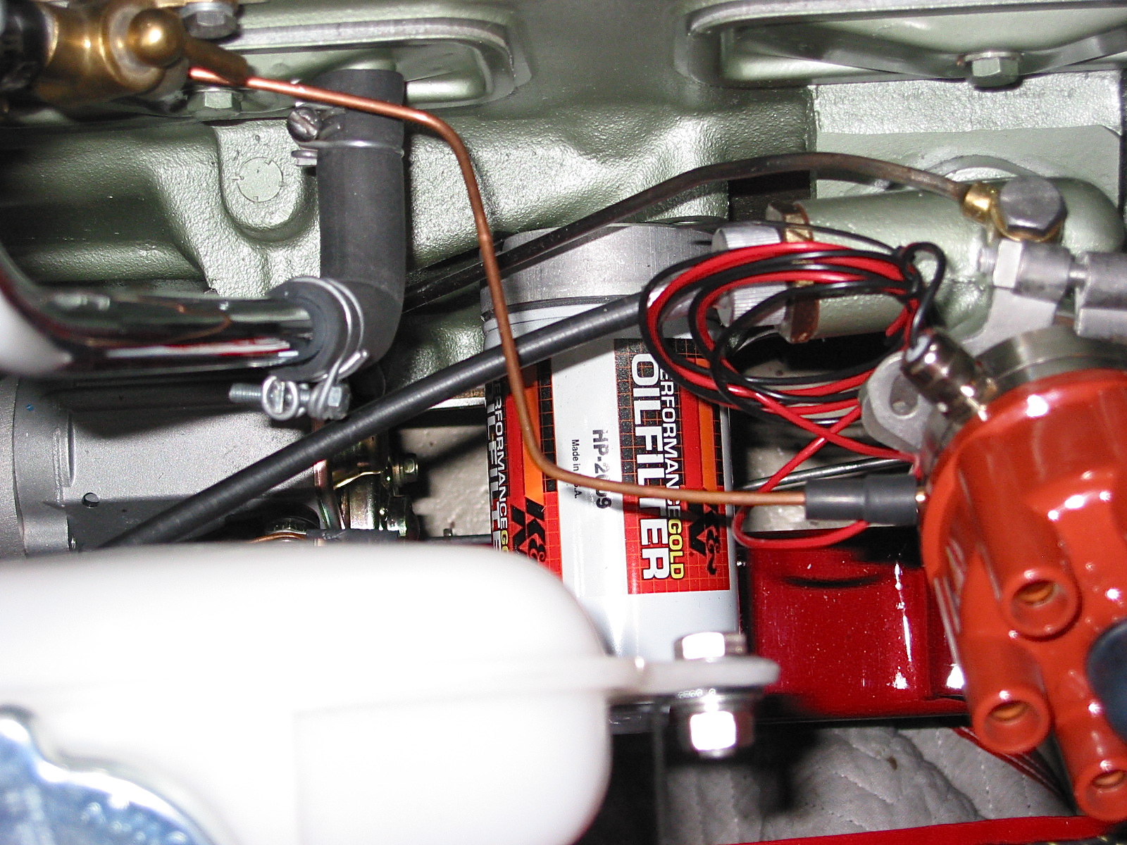
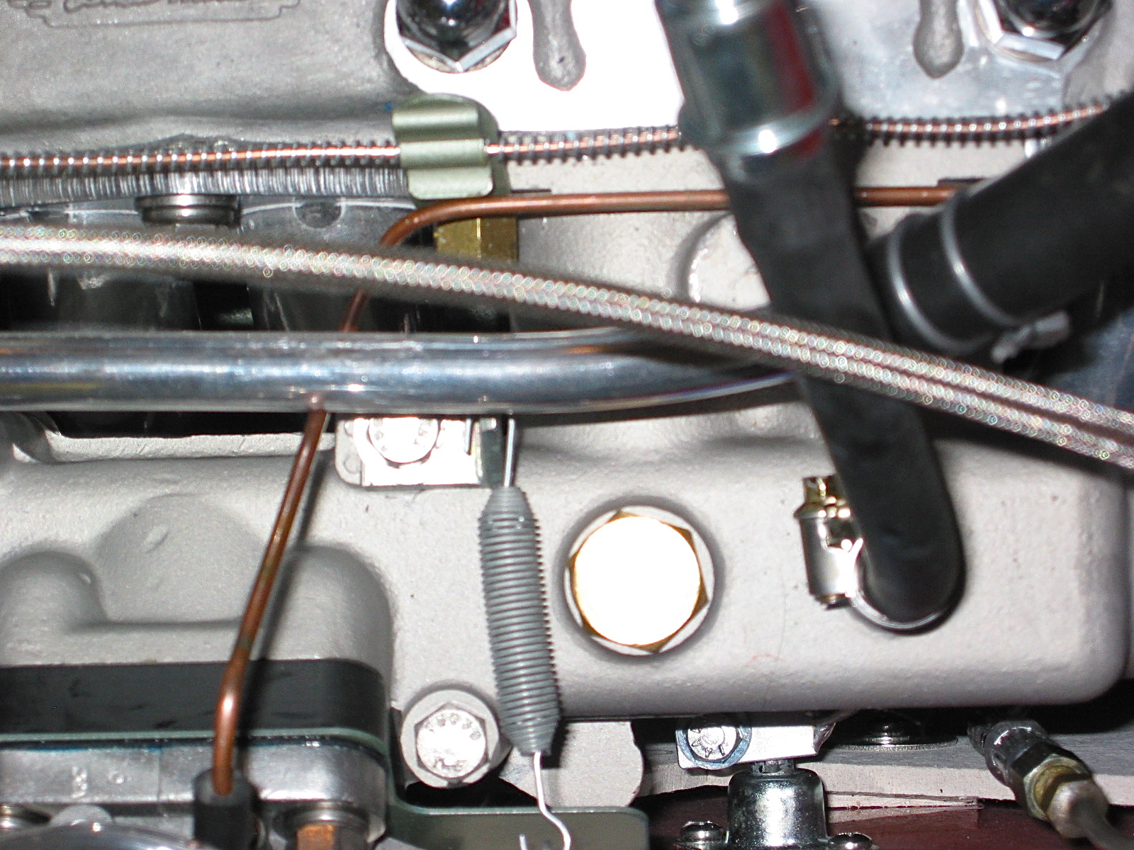
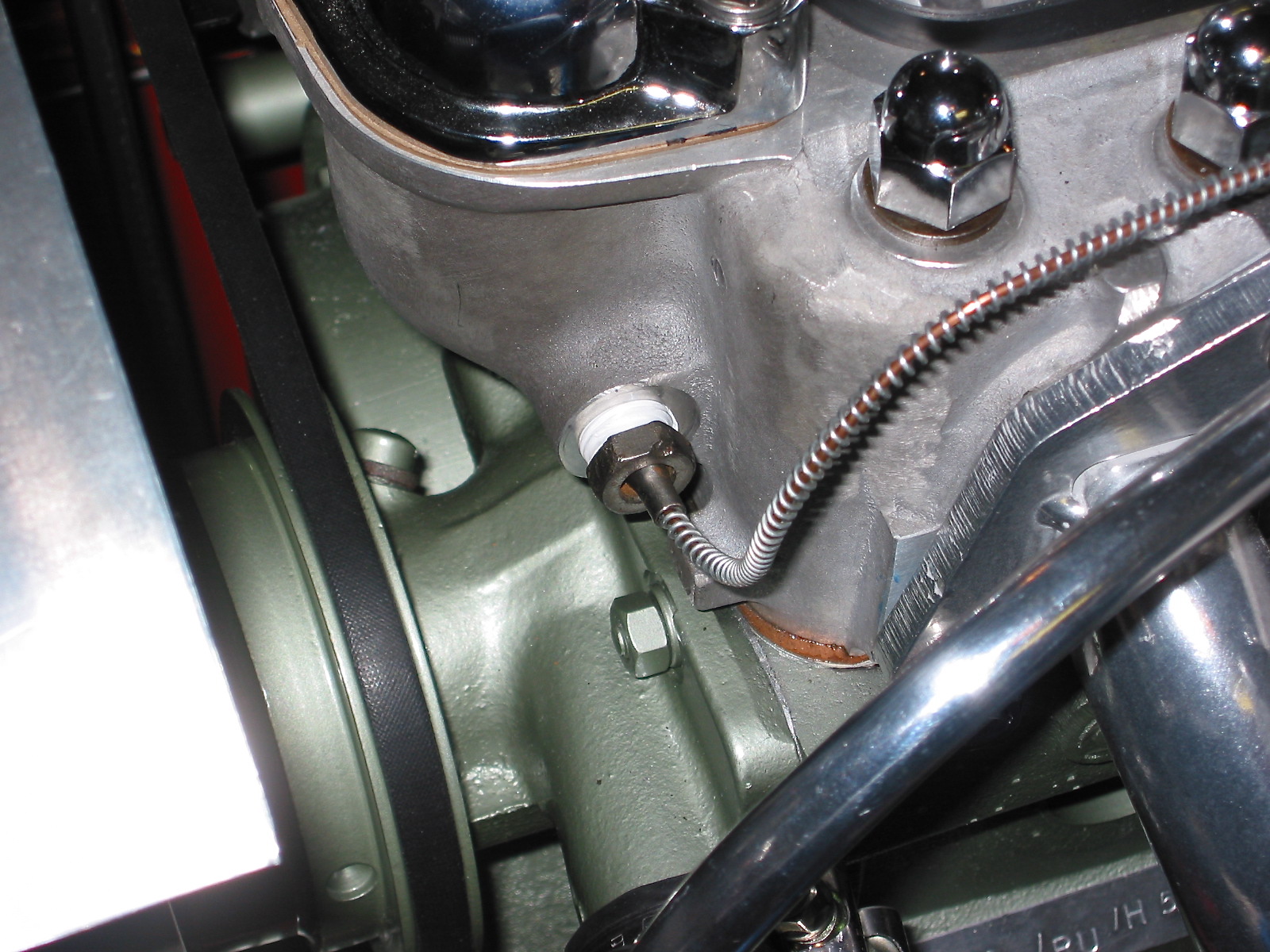
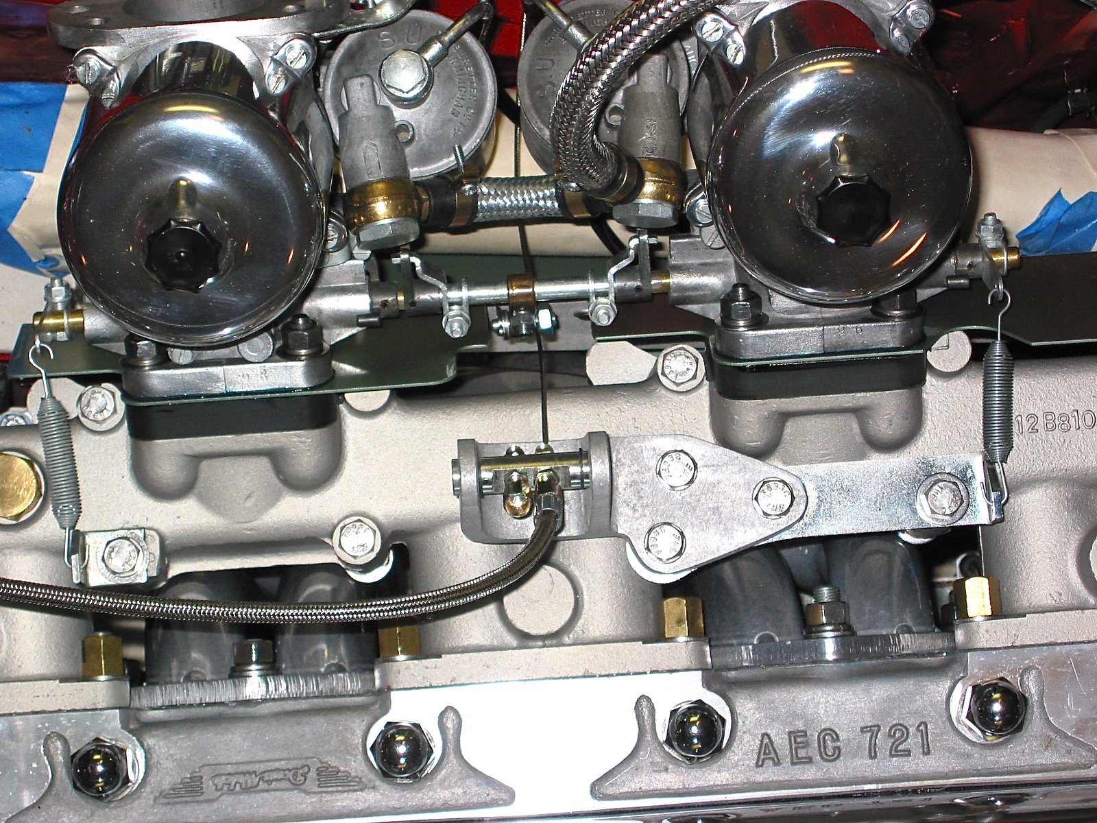
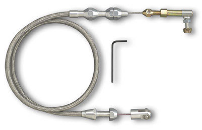
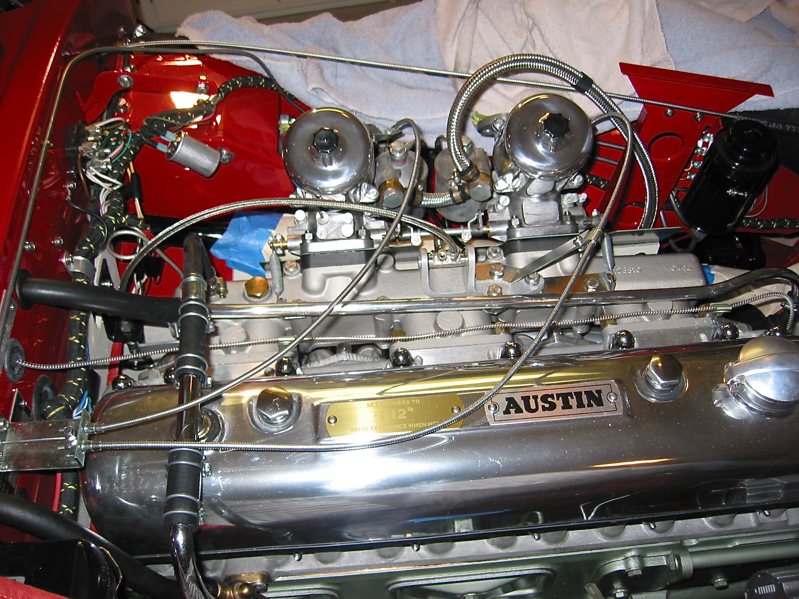
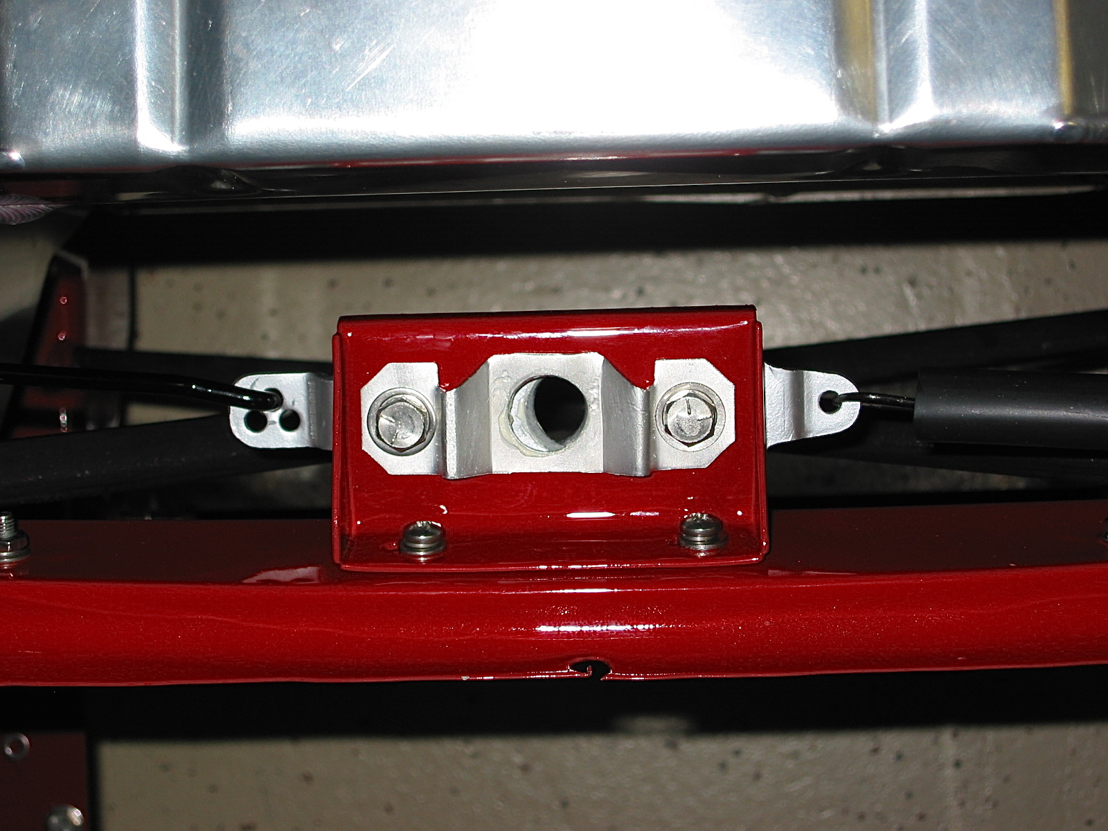
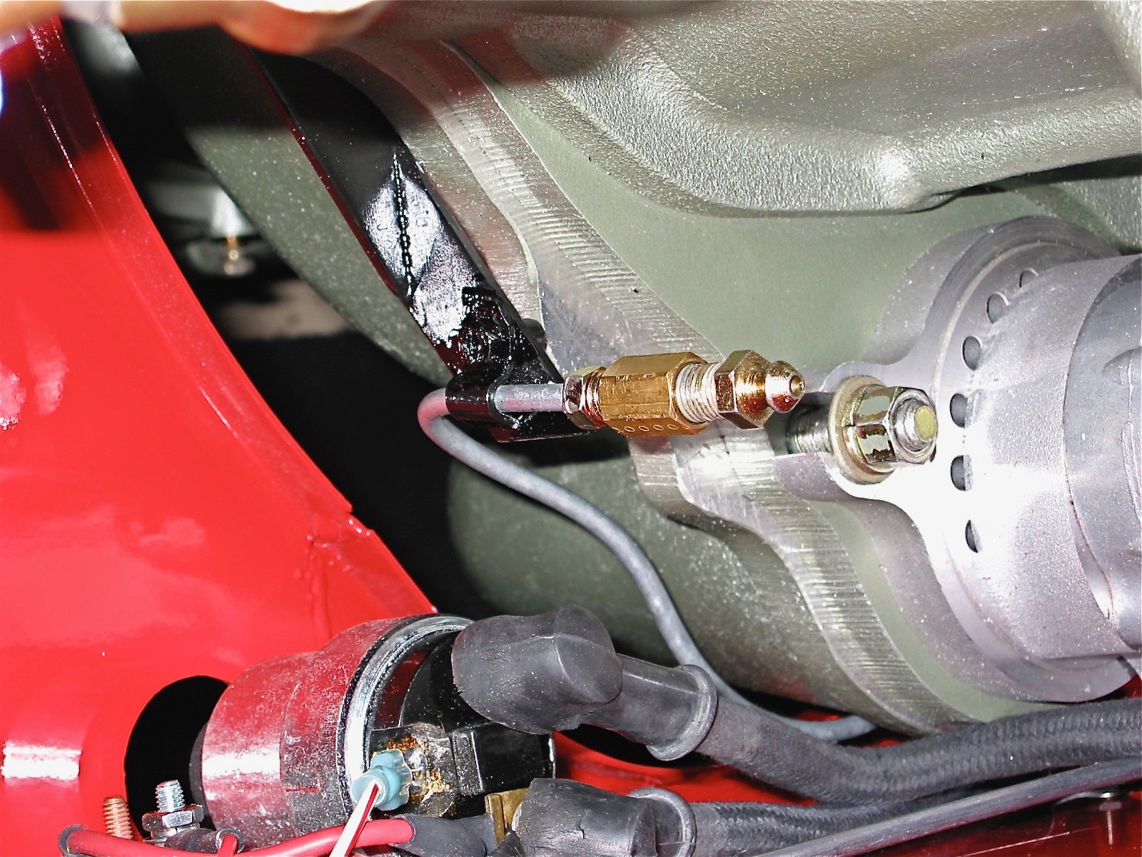
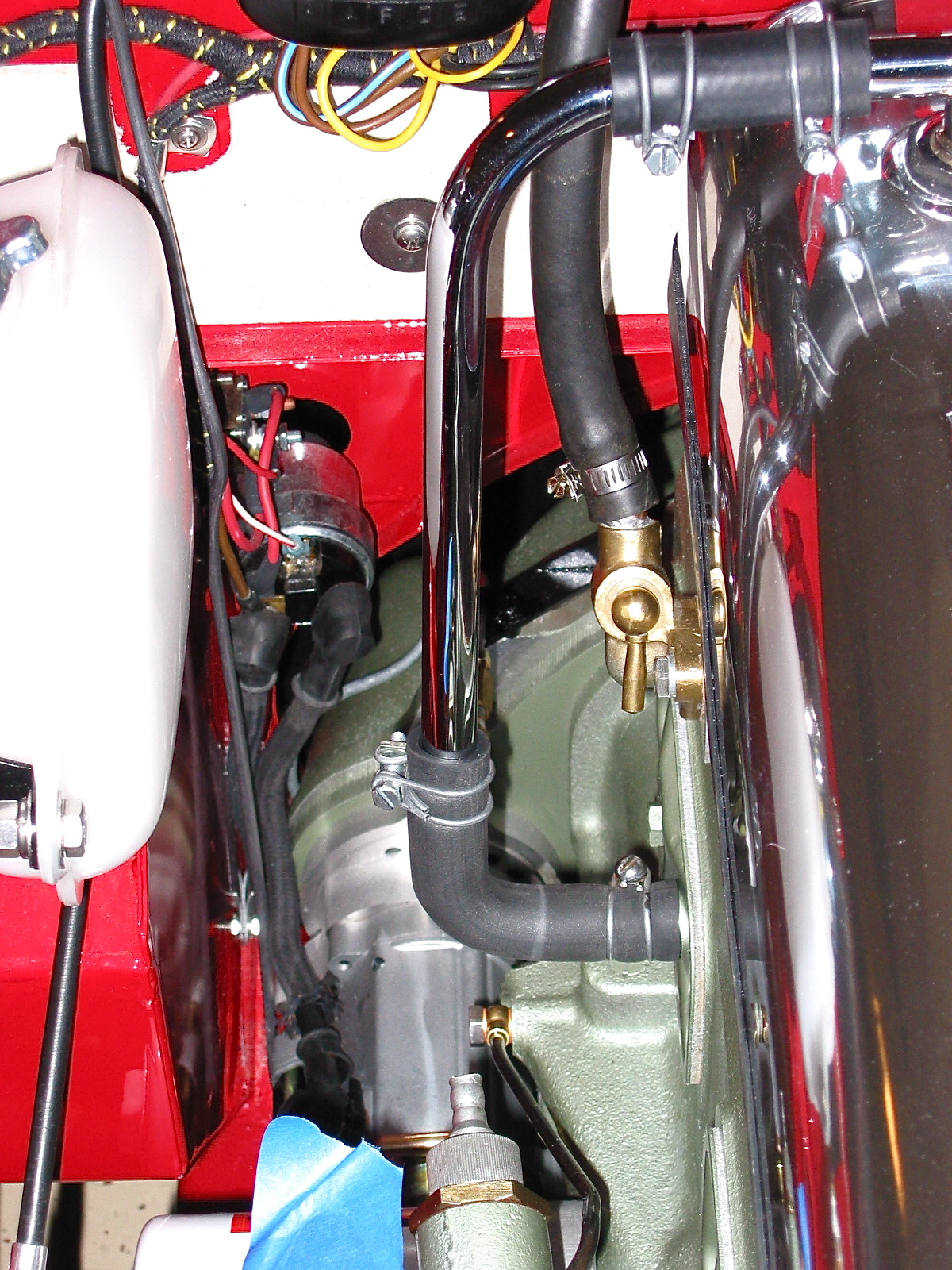
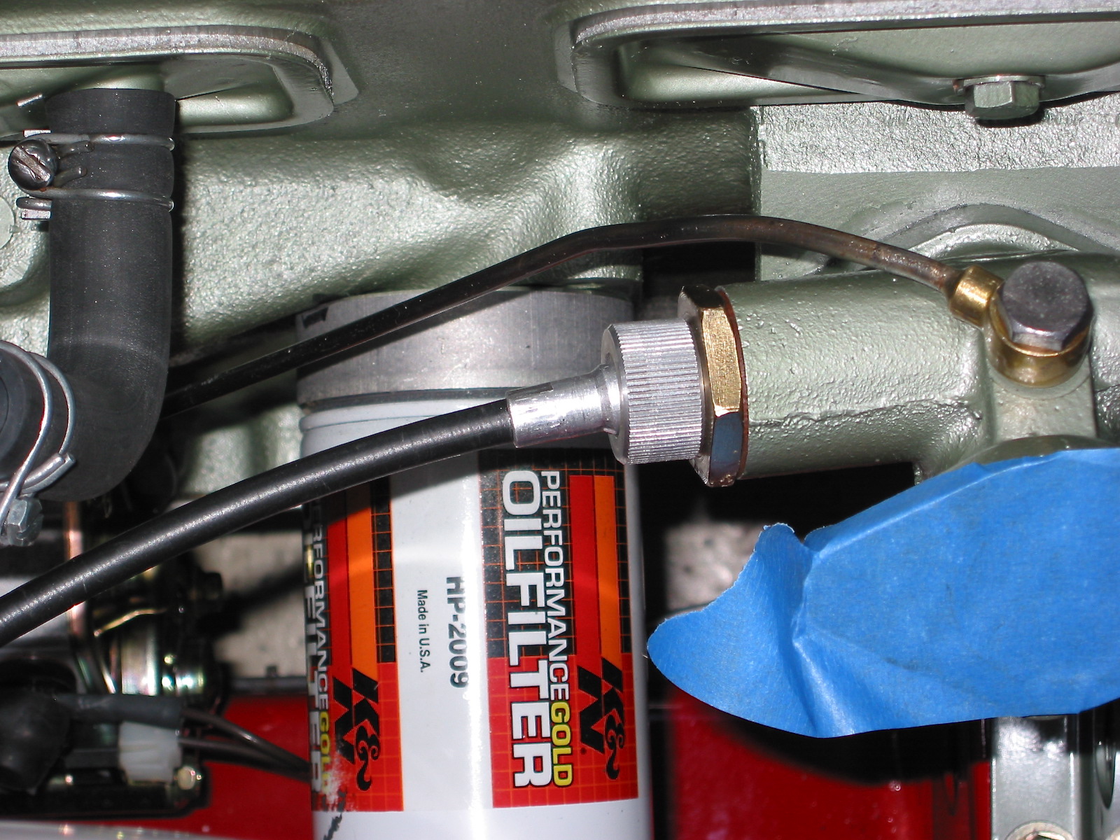
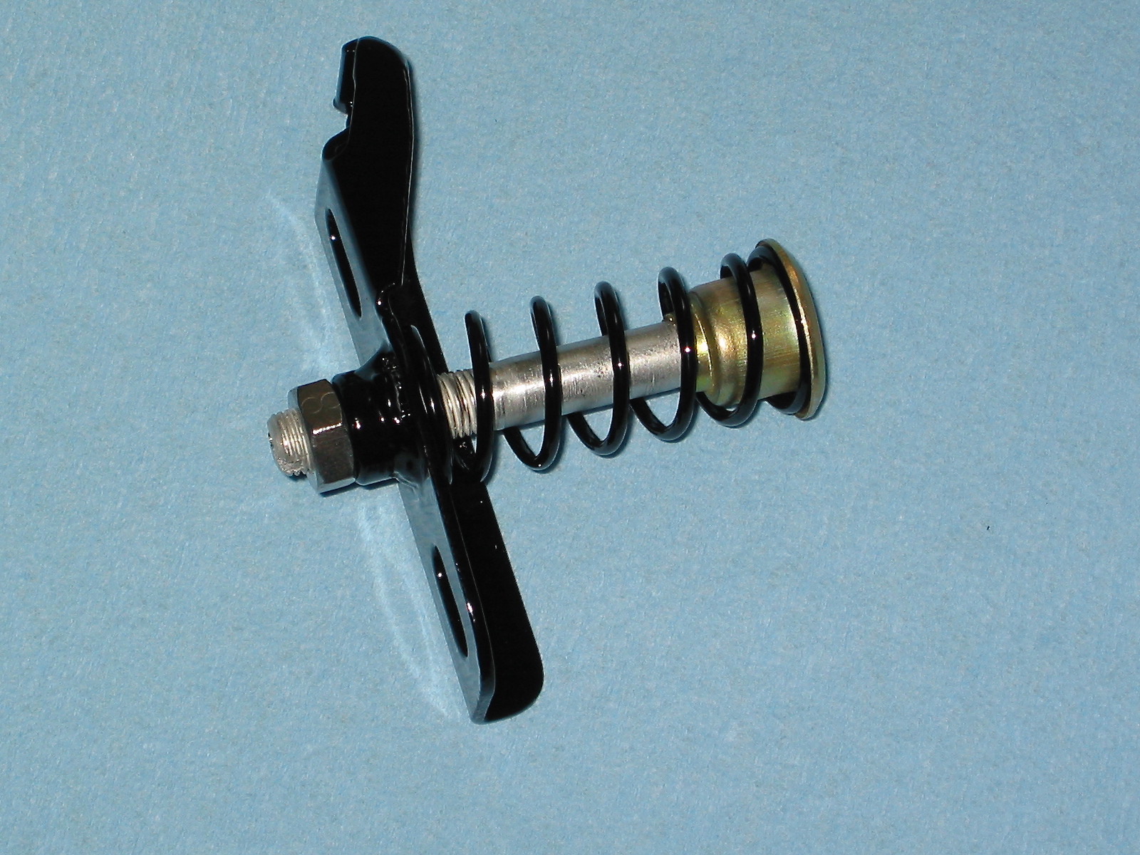
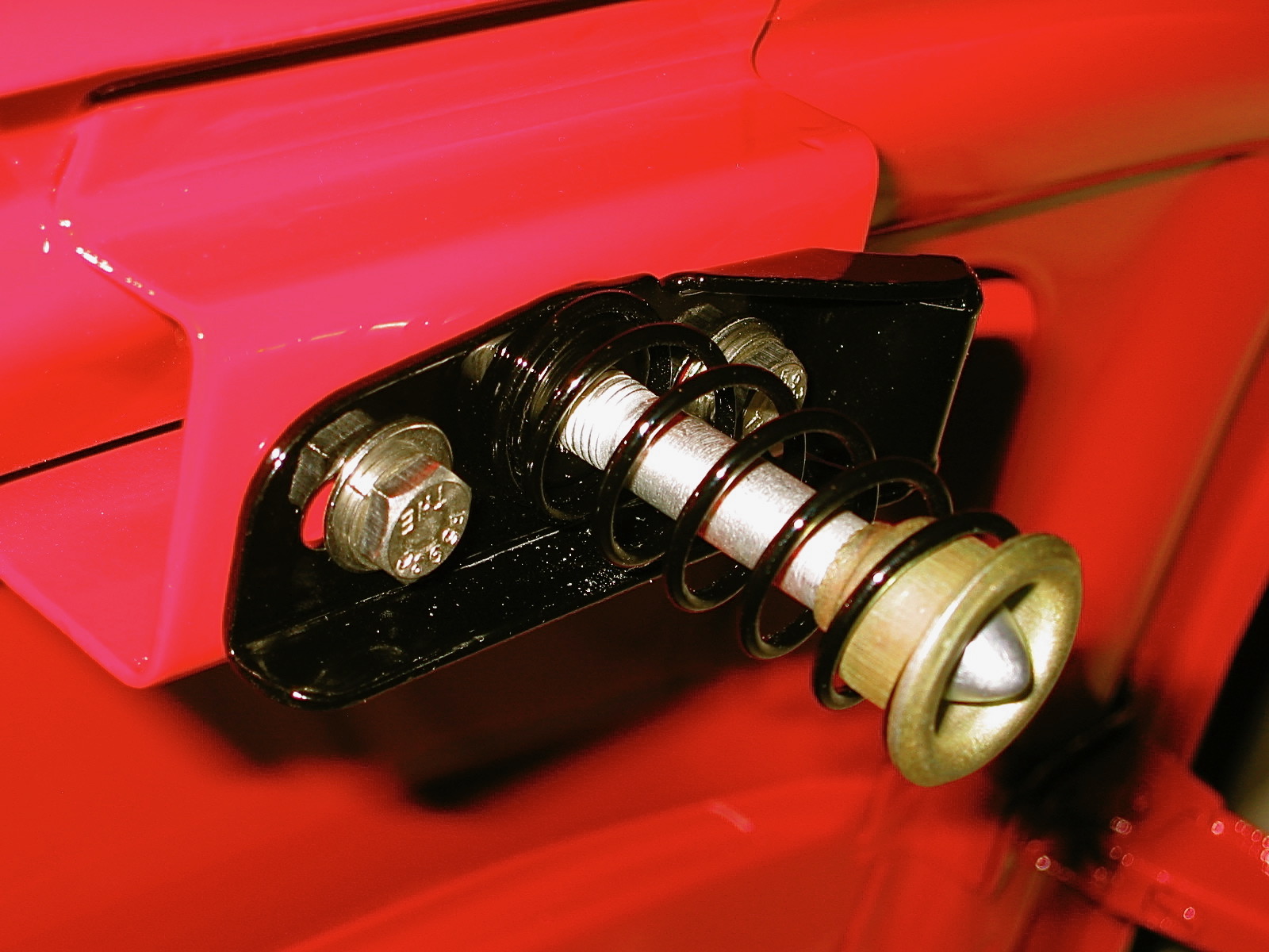
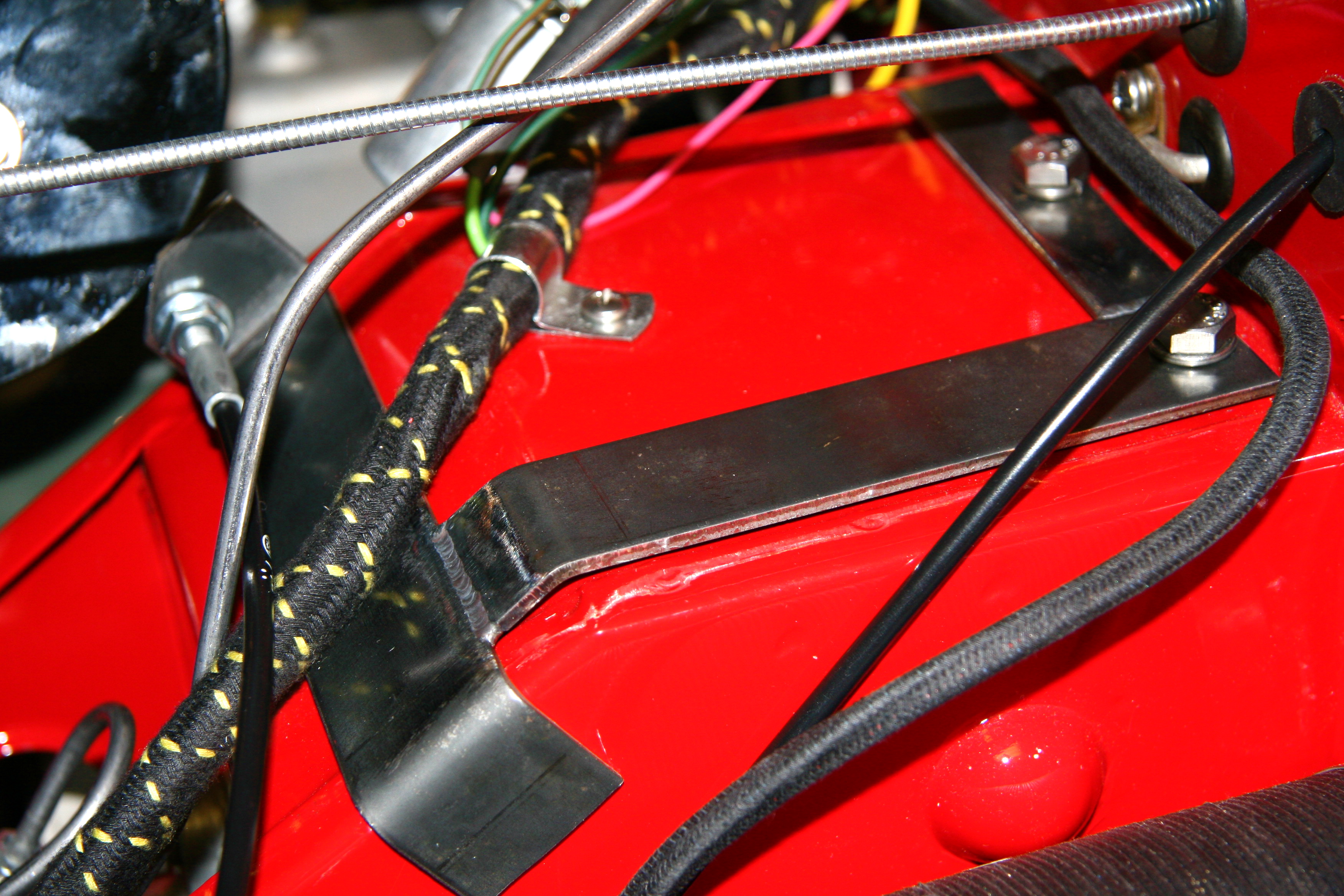
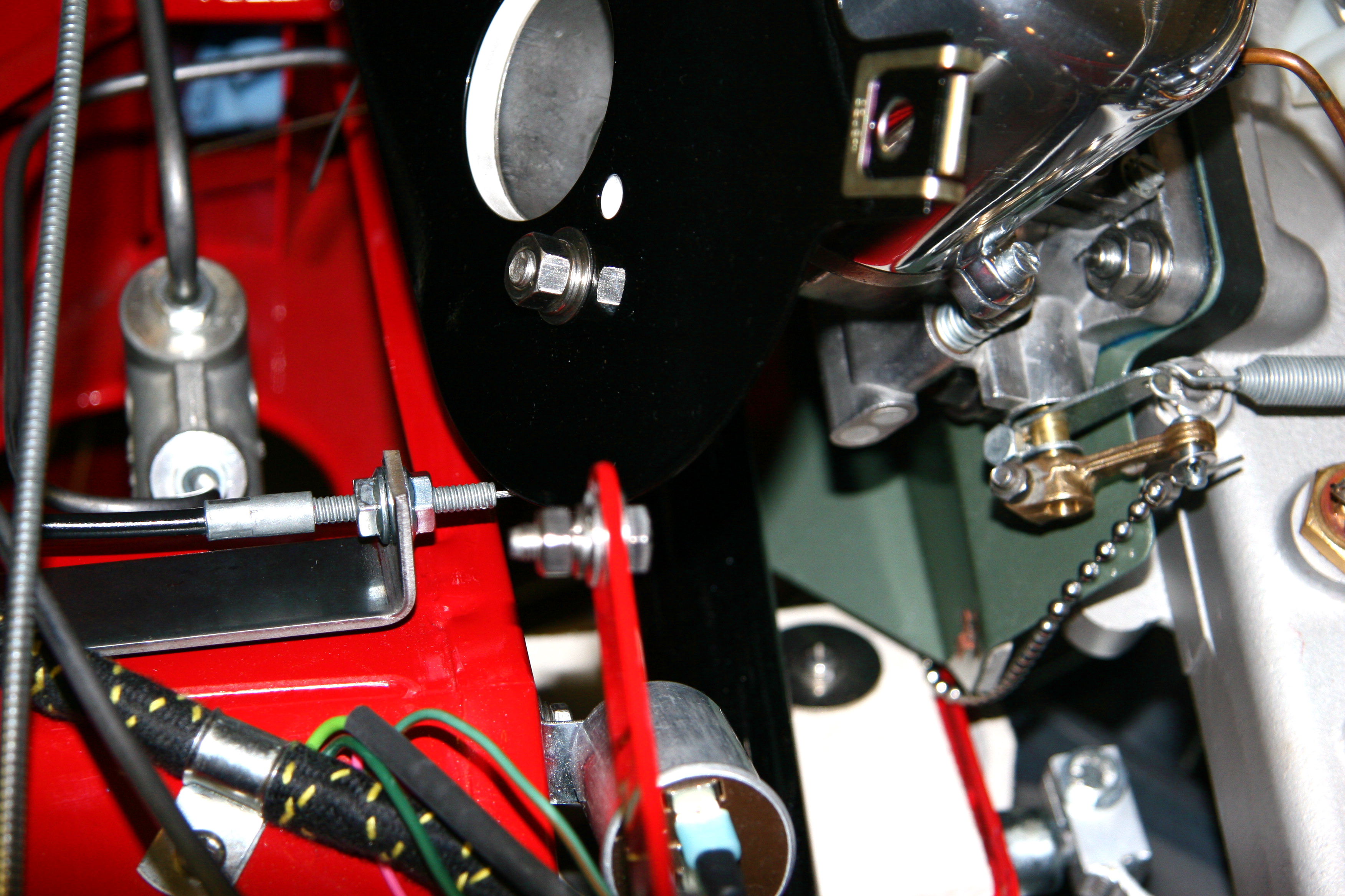
Finishing up the cruise control was accomplished next. I designed a bracket for the throttle connection that permitted locating the throttle cable without having to drill any holes in the vehicle. The cruise control throttle cable bracket is mounted to on the top of the firewall diagonal brace and takes advantage of the two vertical mounting bolts for the pedal box. I painted the bracket red making it virtually undetected by the casual observer.
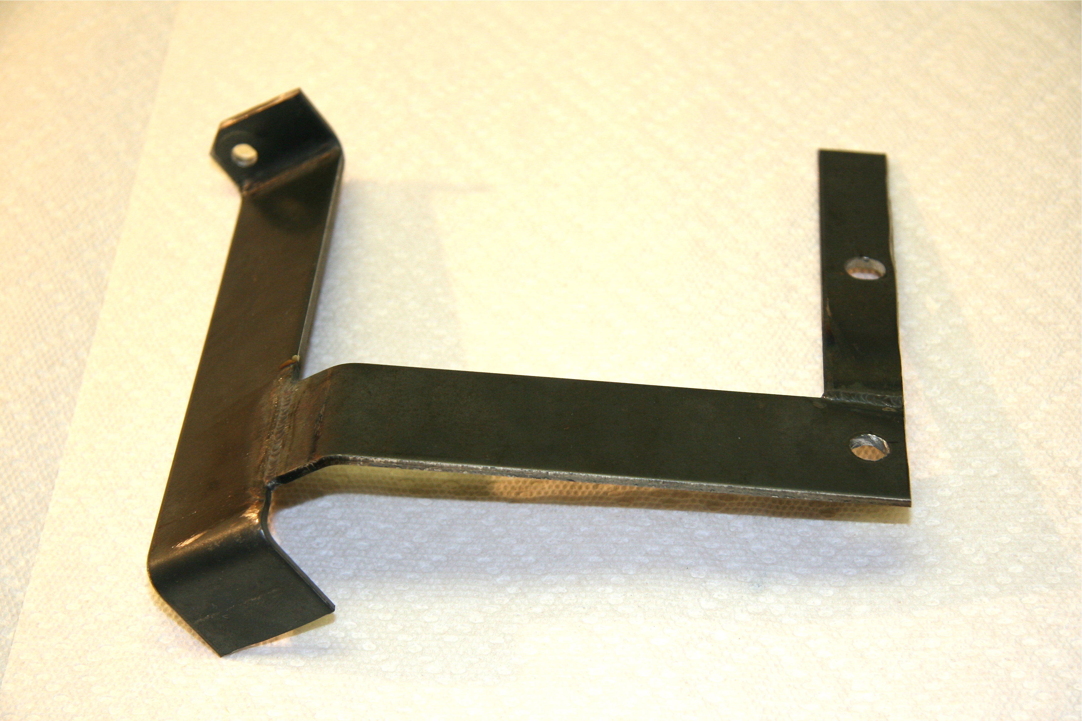
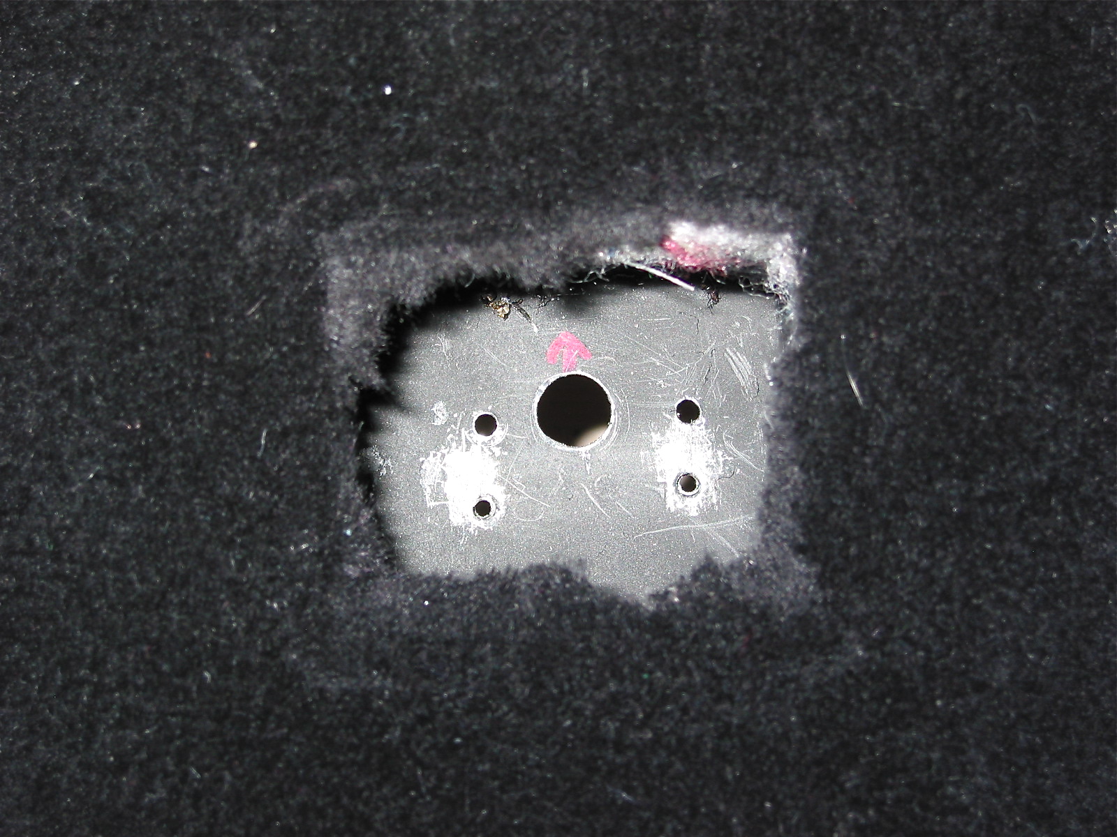
Cruise control bracket 6
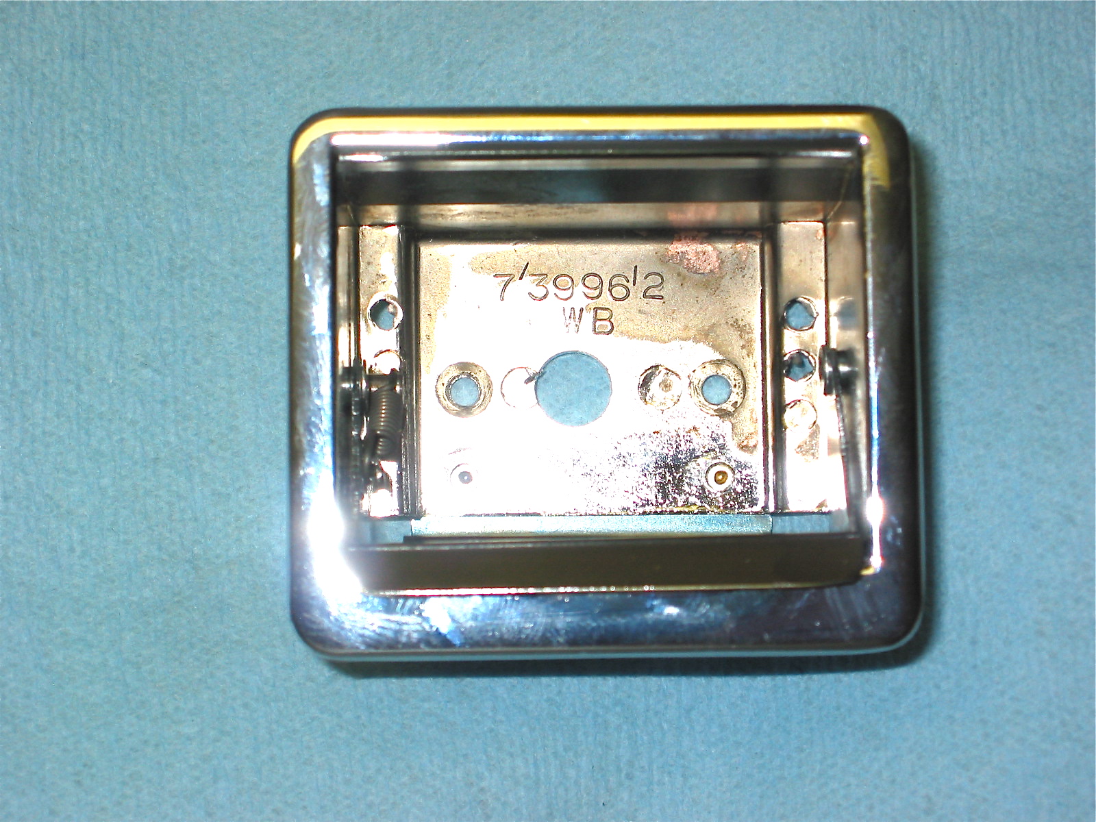
Cruise control bracket 3
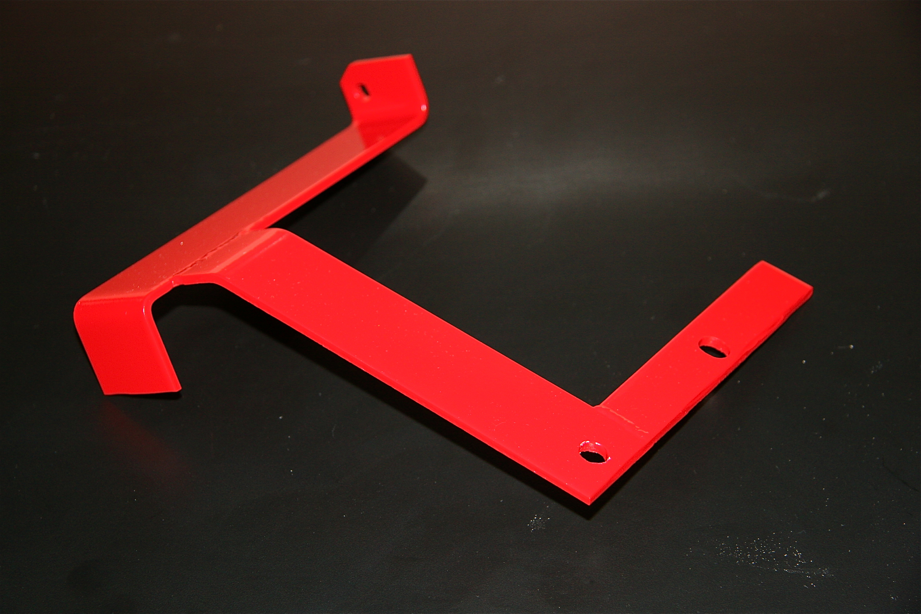
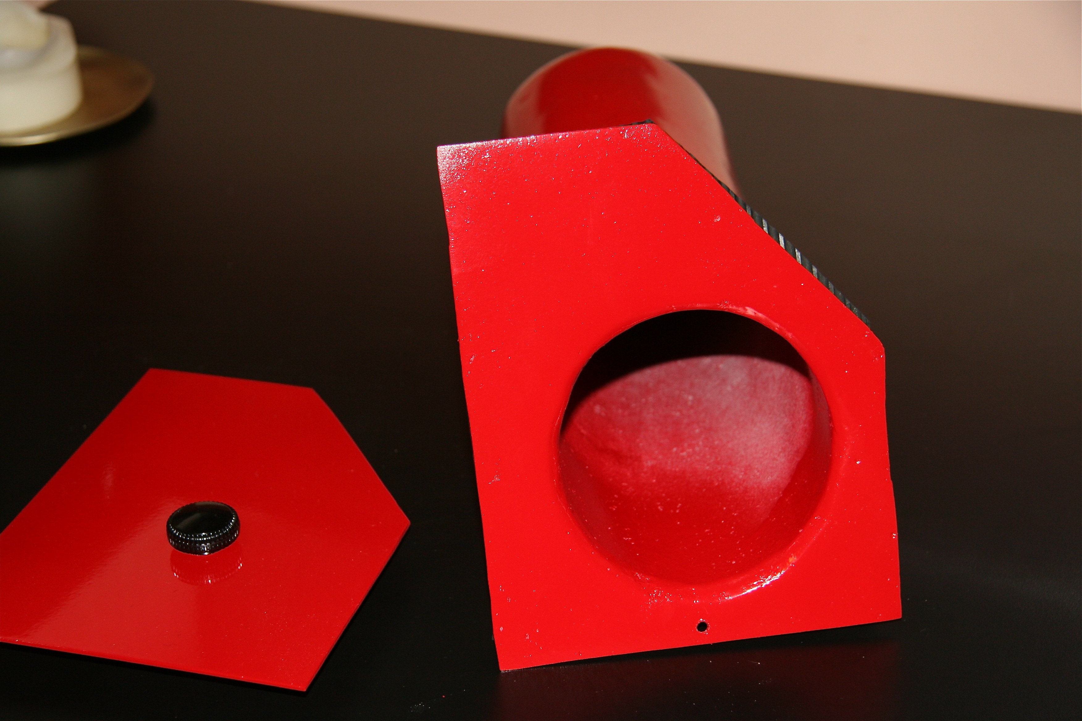
Cruise control bracket painted
Cruise control bracket 5
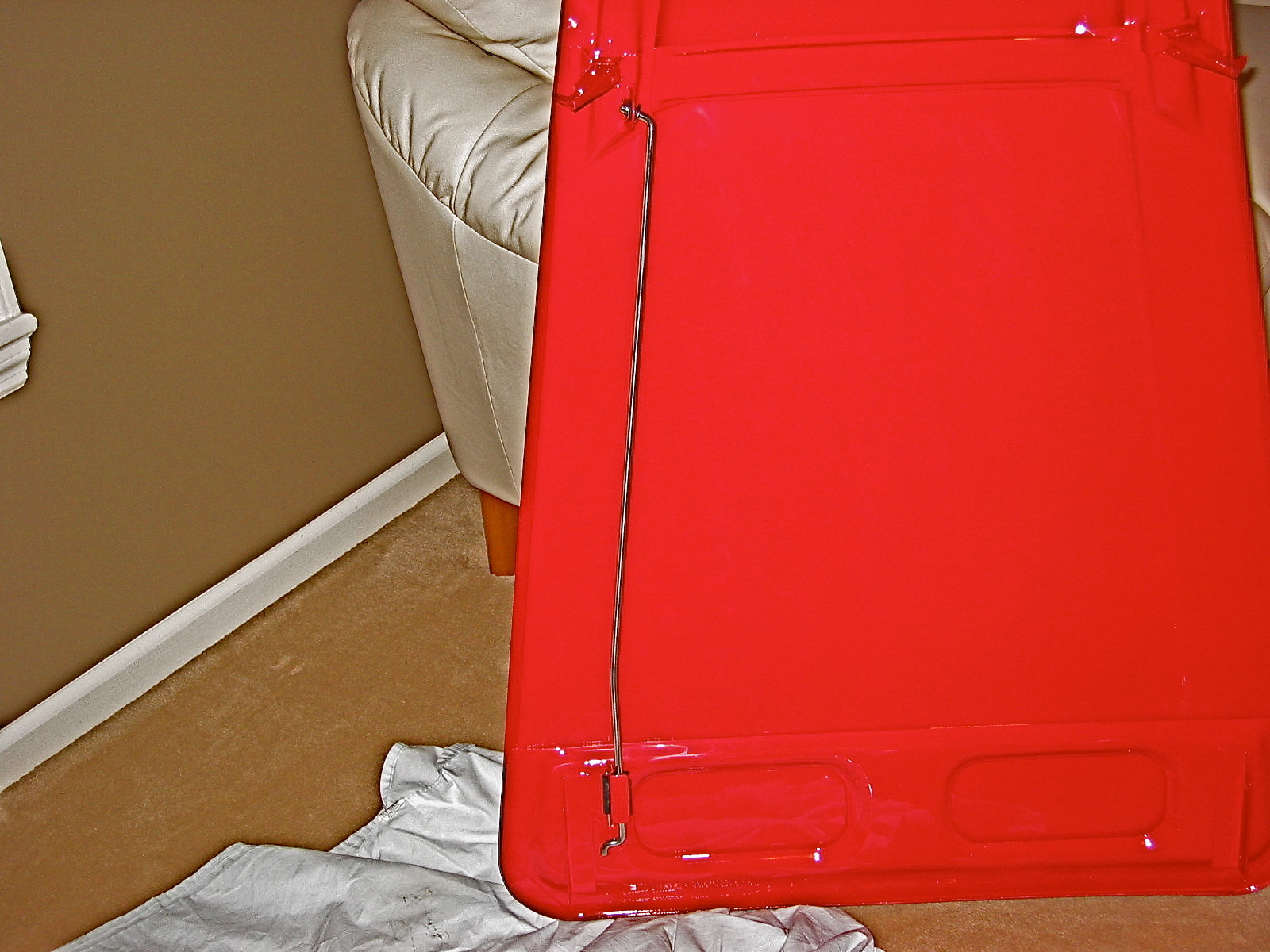
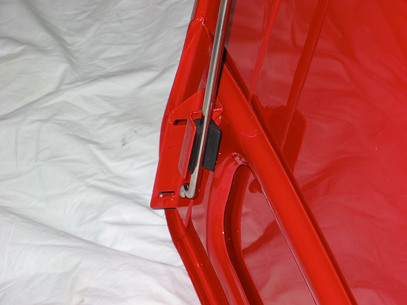
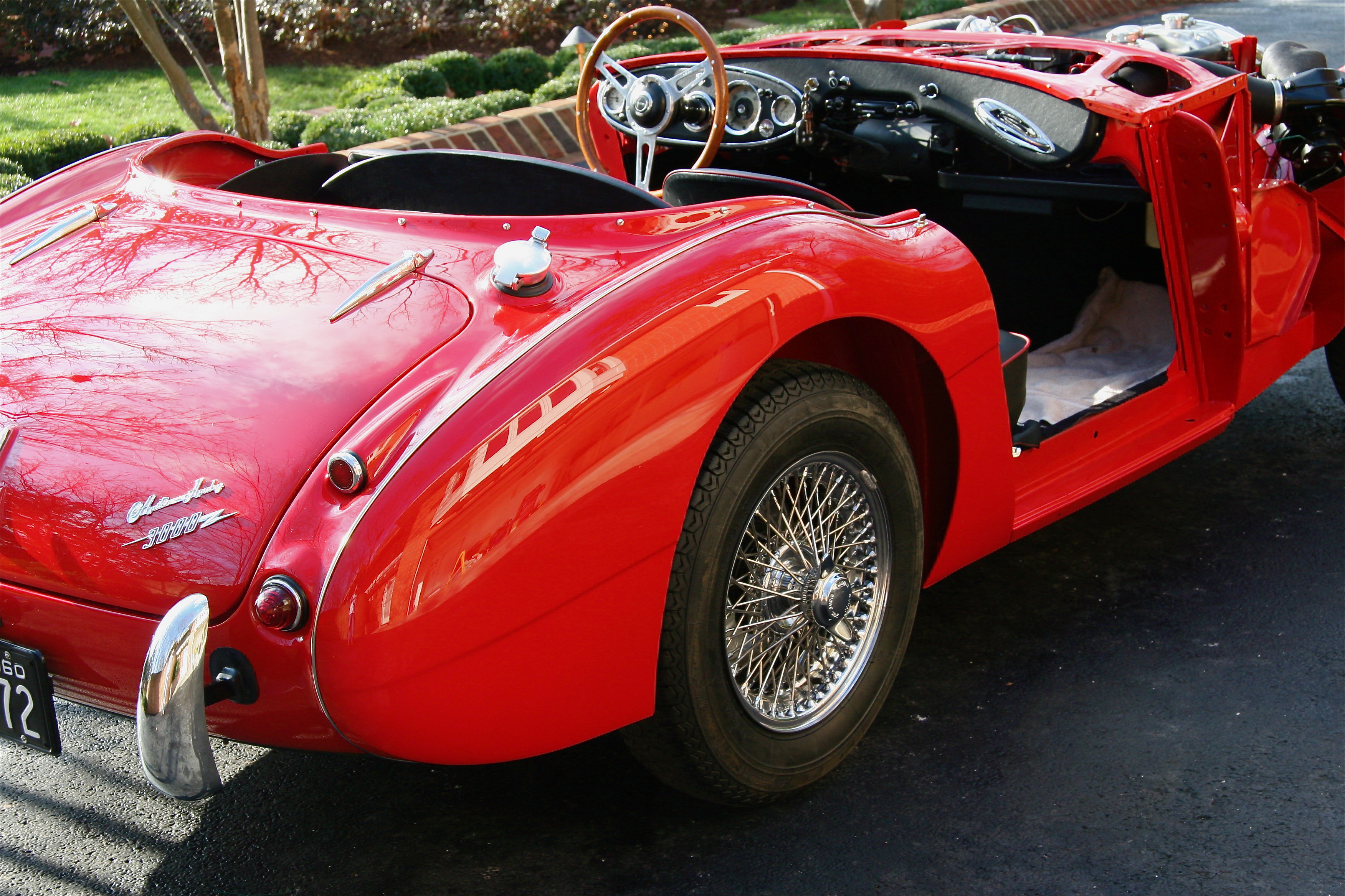
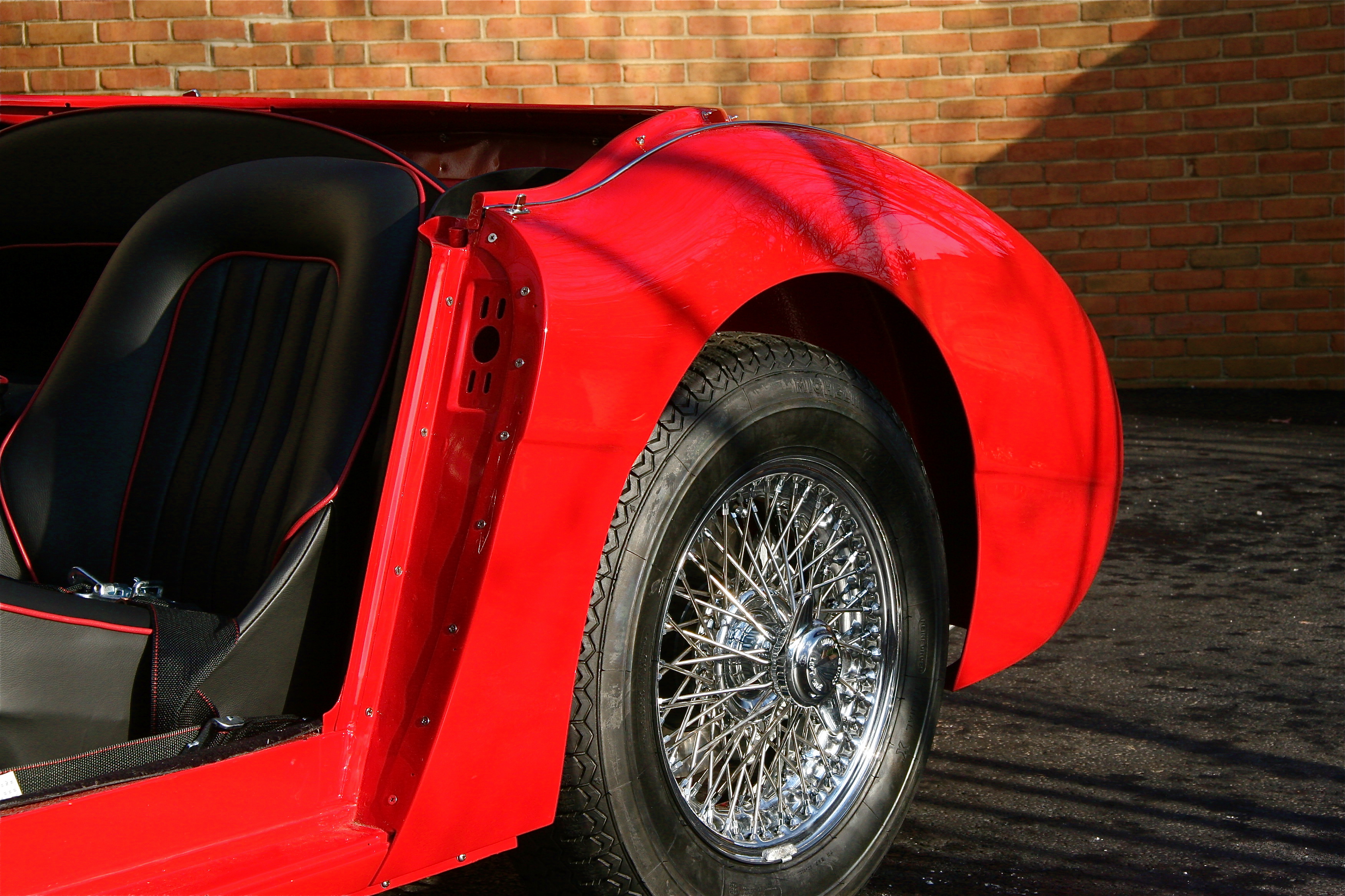
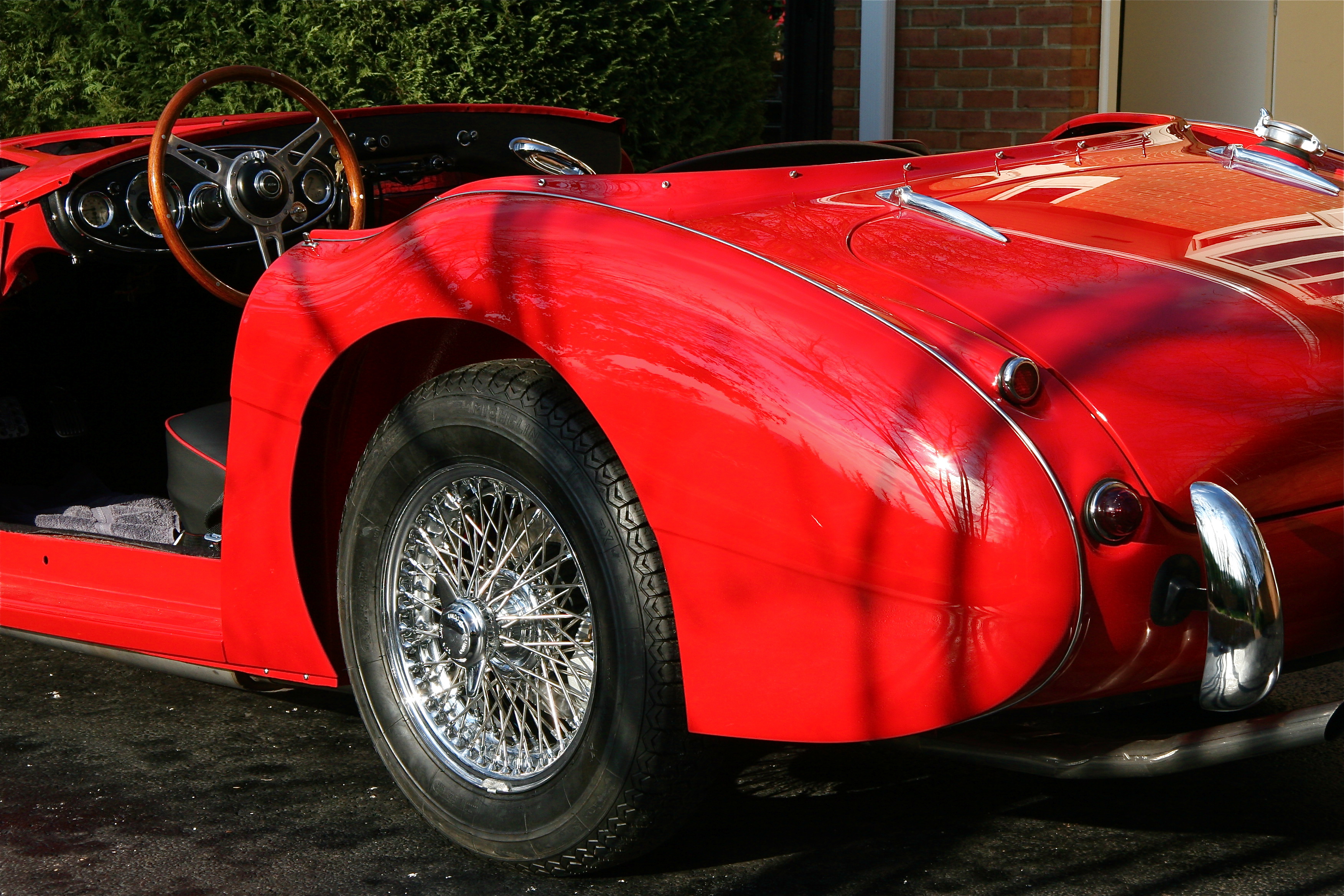
Using what I learned on the installation of the RH rear wing, I attached the LH wing in about half the time. I fixed the turnbuckle to the wing before putting the wing on the superstructure.
Turnbuckle installed
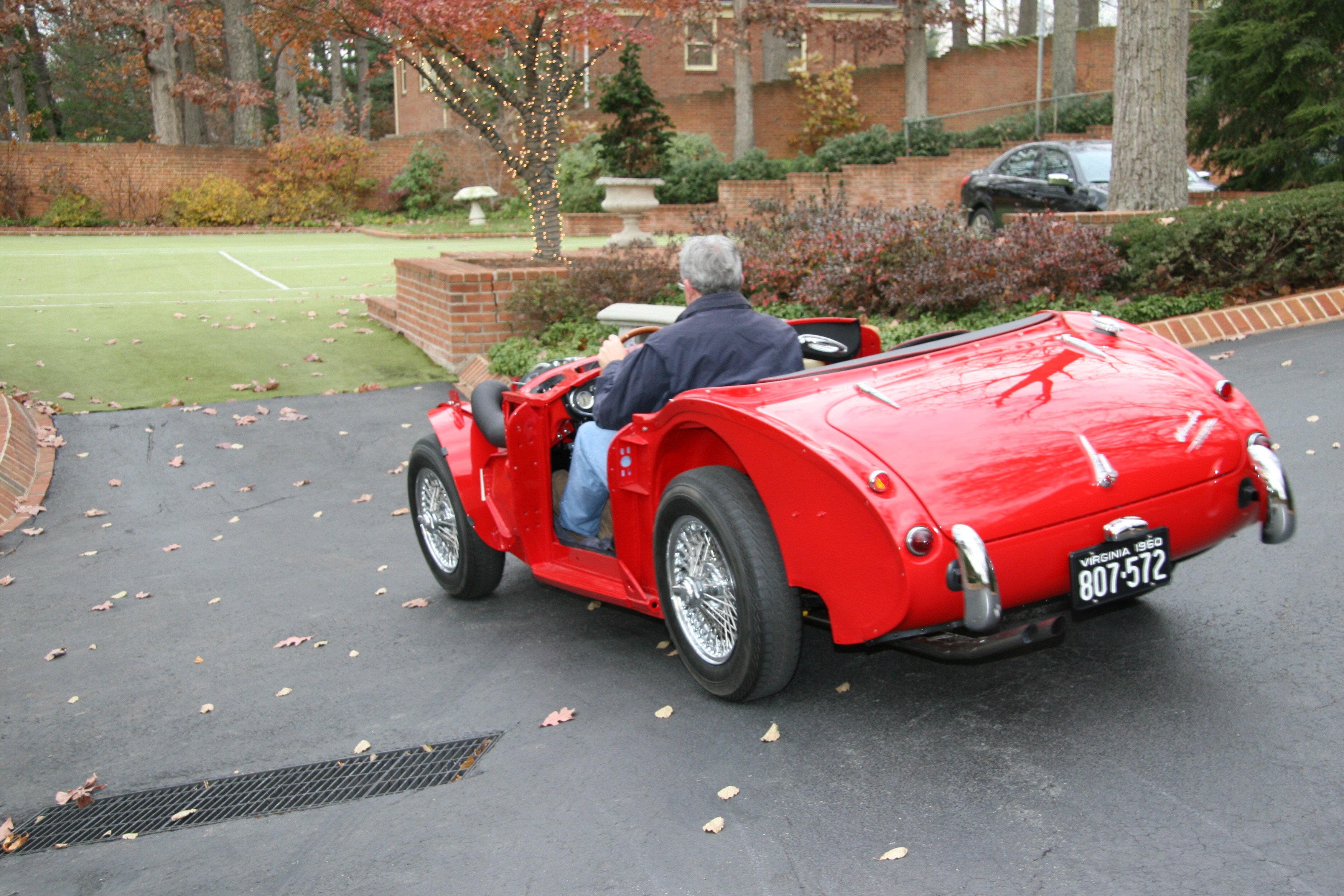
It is a good feeling to have both installed. The Beast is actually beginning to look like a car.
RH Rear Wing 1
LH rear wing 2
LH Rear Wing 1
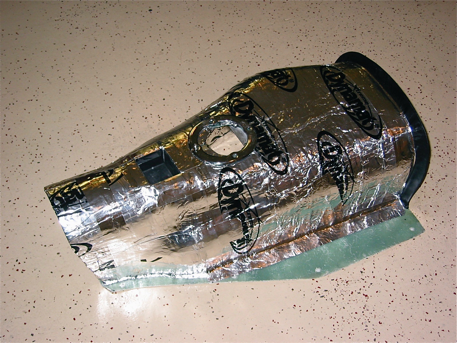
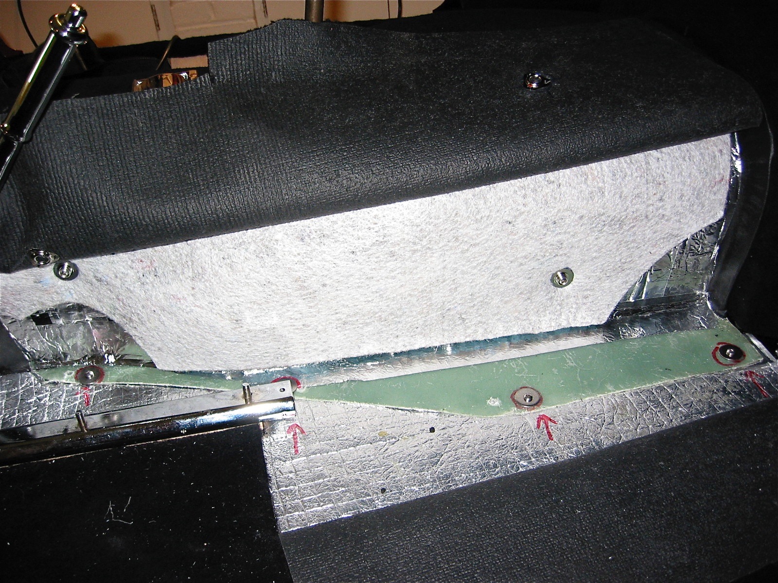
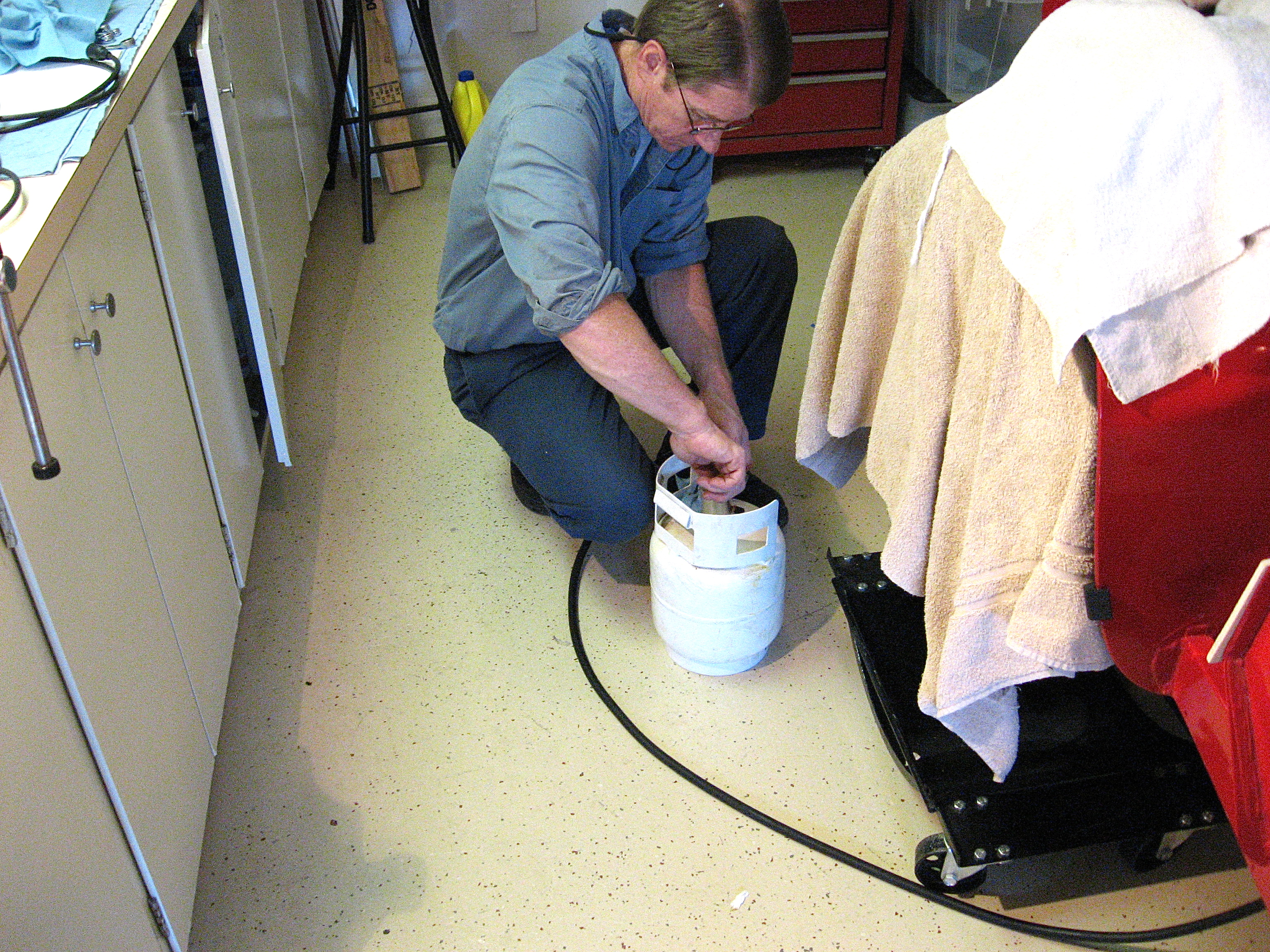
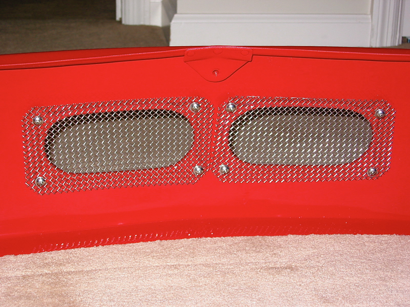
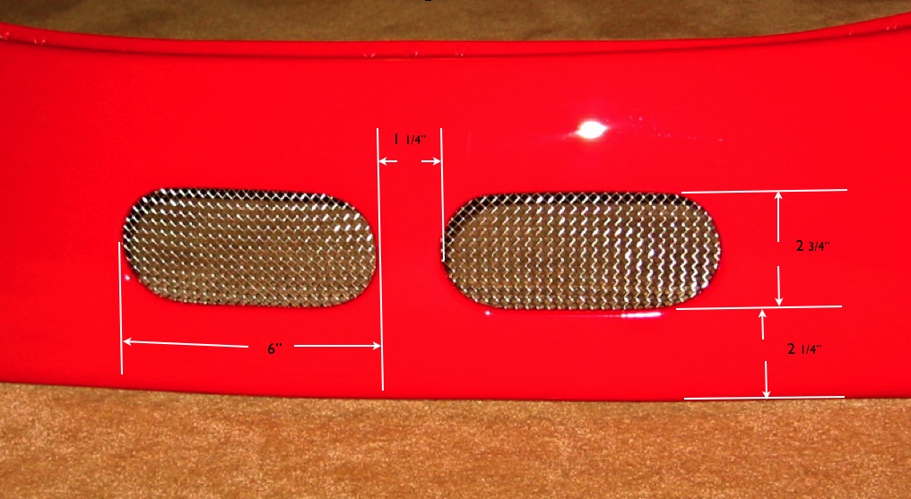
I had my local auto paint store make two body paint spay cans as well as two small bottles for touch up work. I then spray painted the stow-it tube I had made from fiberglass back in the summer along with a sheet metal top I made with the top of the scotch bottle box fastened to the lid. It will be very unobtrusive, and will provide some nice under shroud storage for parts or tools. I borrowed the idea from Tracy Drummond – thanks Tracy.
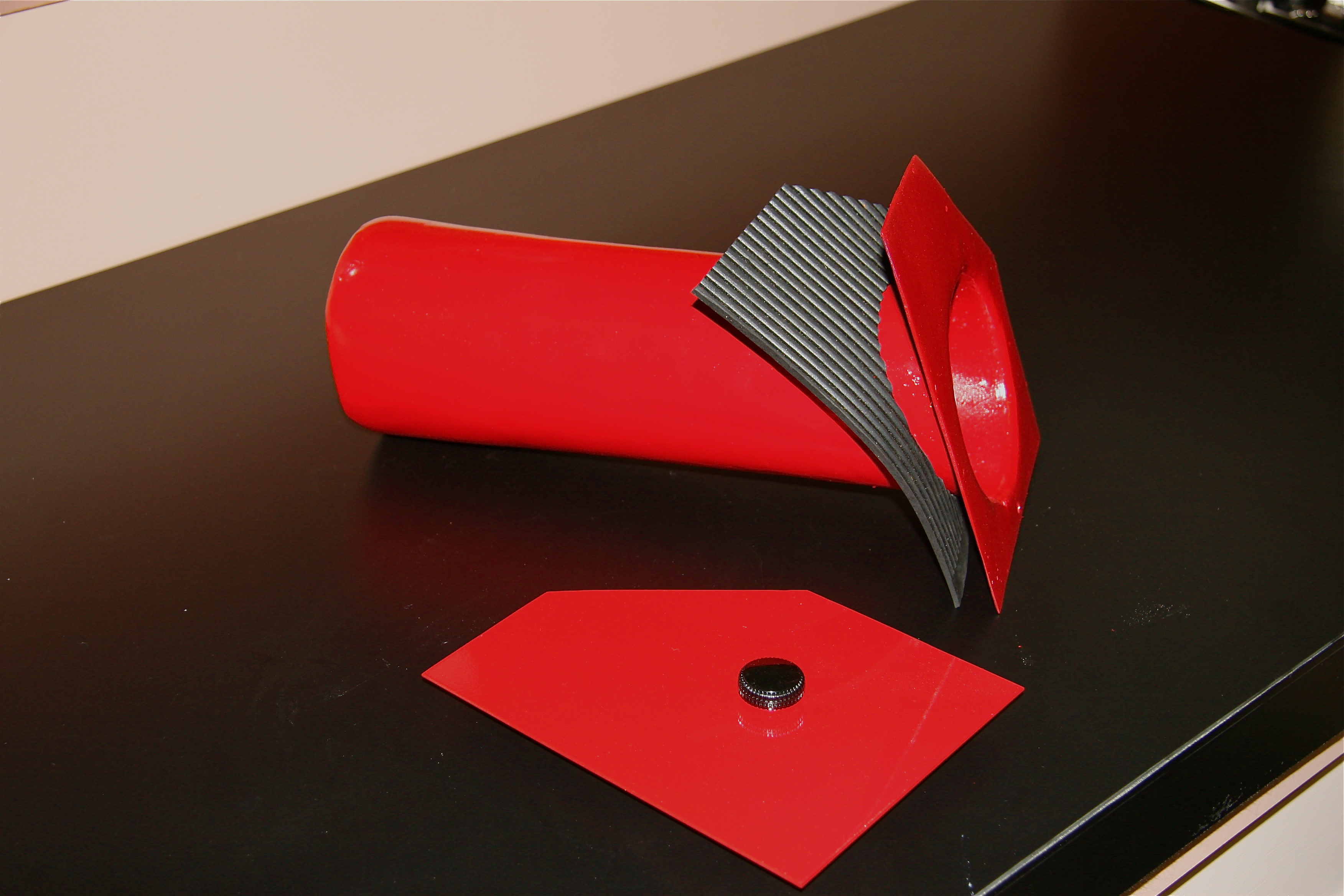
Stow it tube painted and with gasket and top
Stow it tube 2
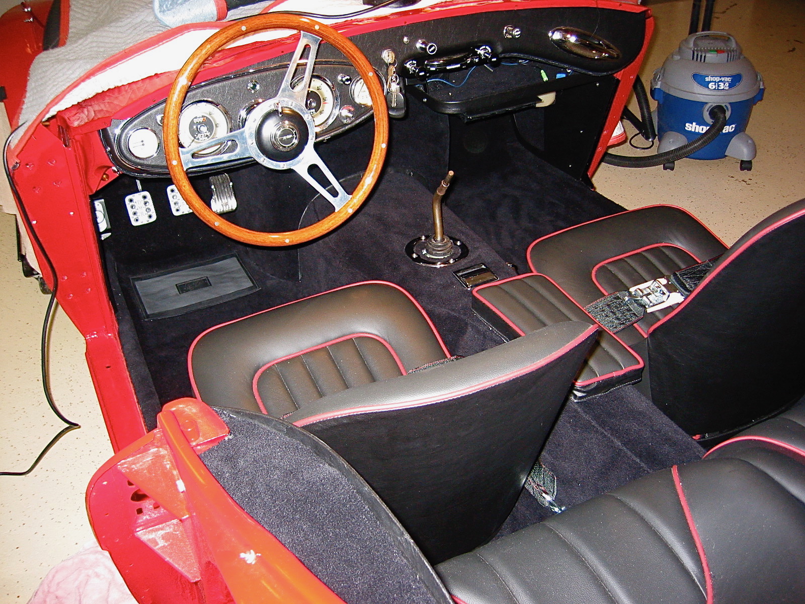
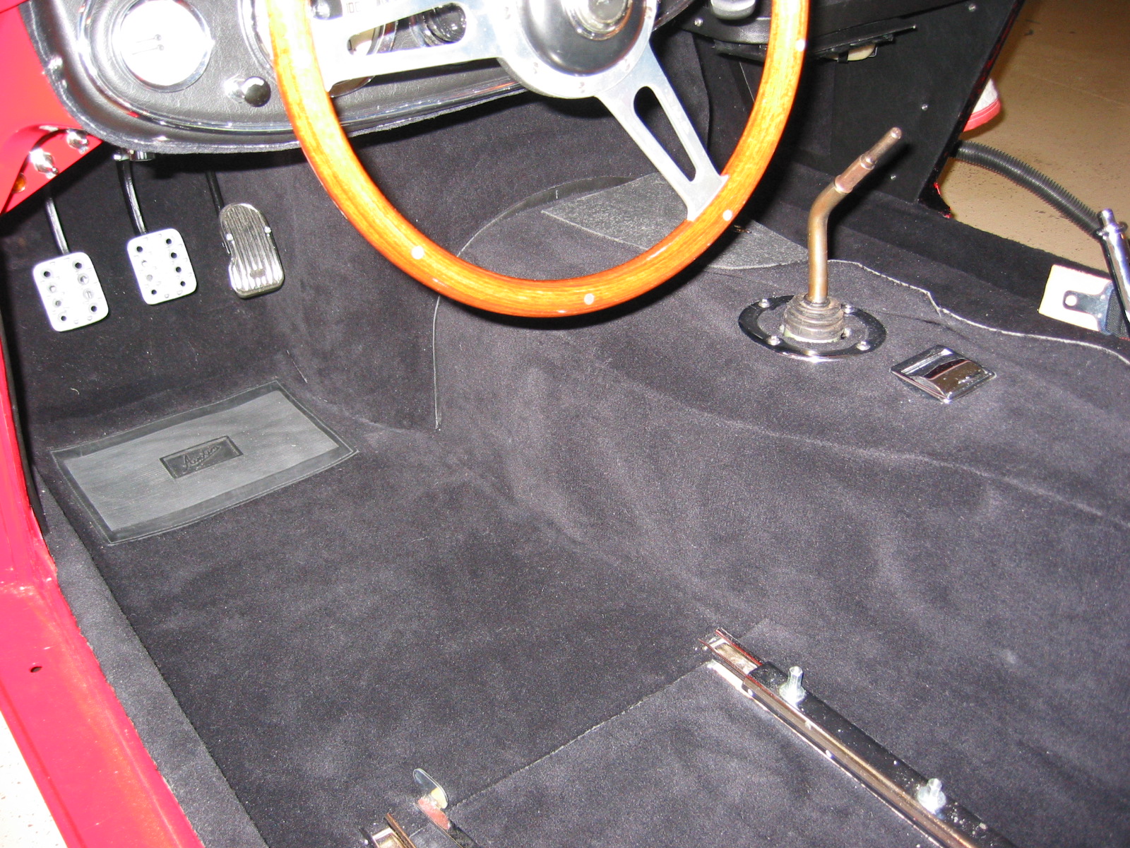
My carpenter finished the transformation of my shoe box model for a console to the real thing in wood. He did a beautiful job. I inserted the wood lid into the underside of the padded arm rest from Heritage and then covered the box in black carpet. Now I have something that almost looks as original, and it also is comfortably functional! The top is hinged and it has a lower tray to stow small items.
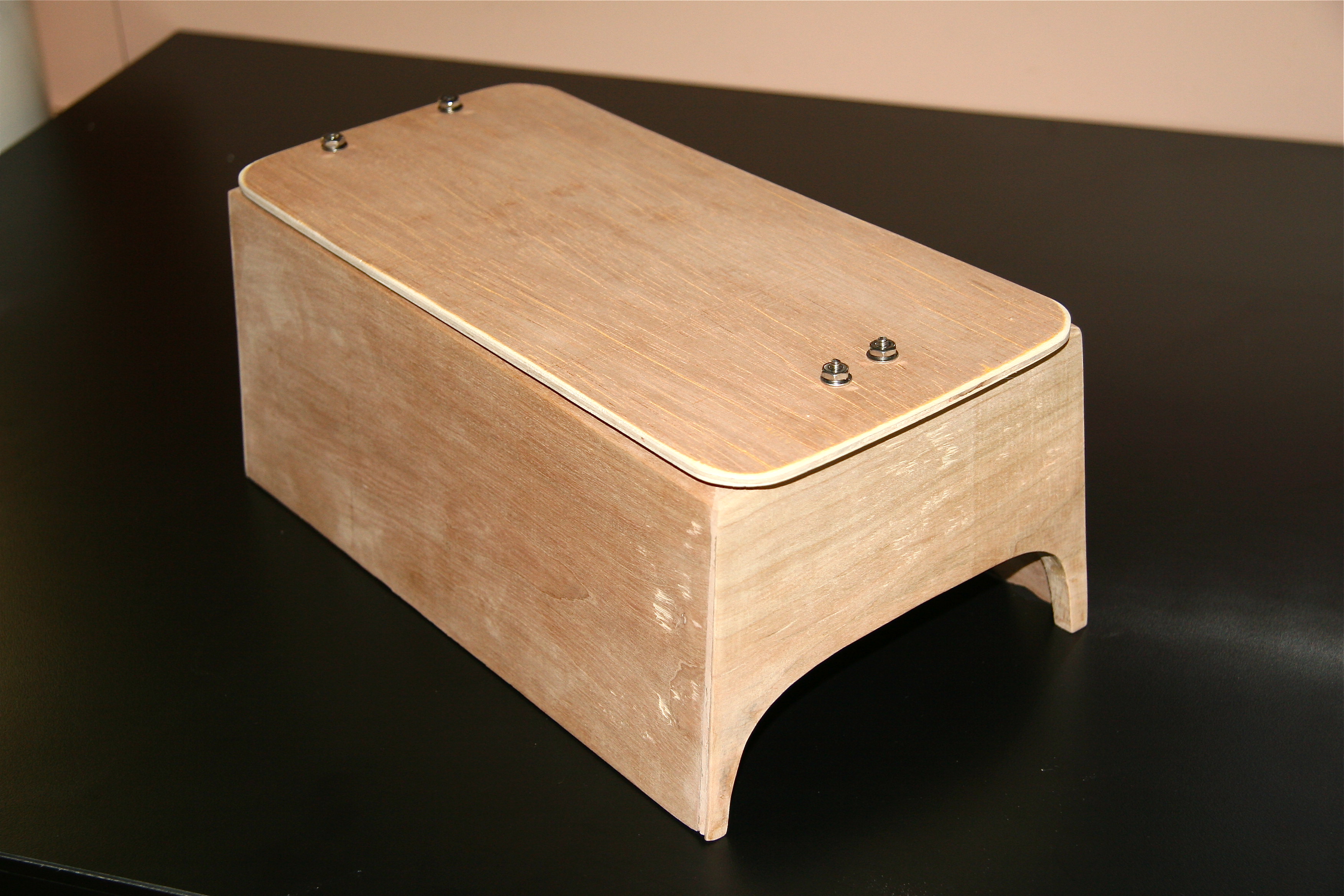
Console 1

Console 3

Console 7
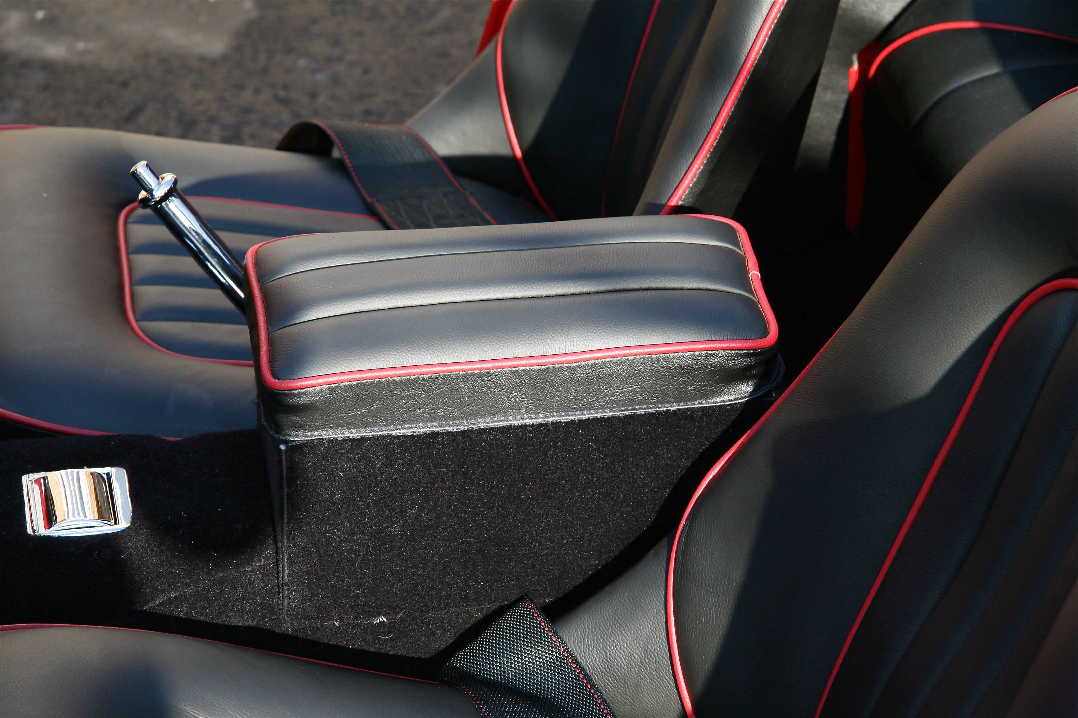
Console Installed
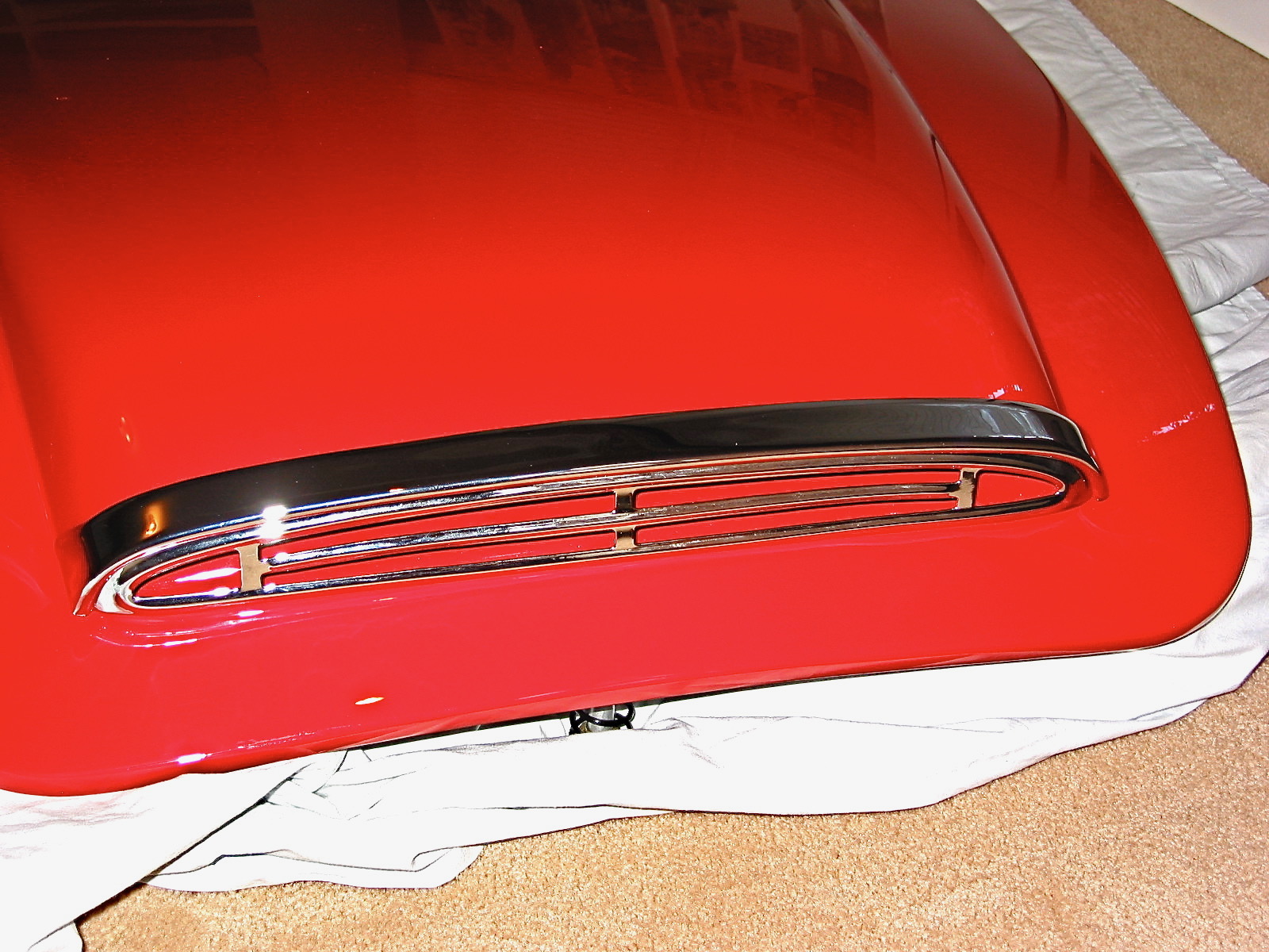
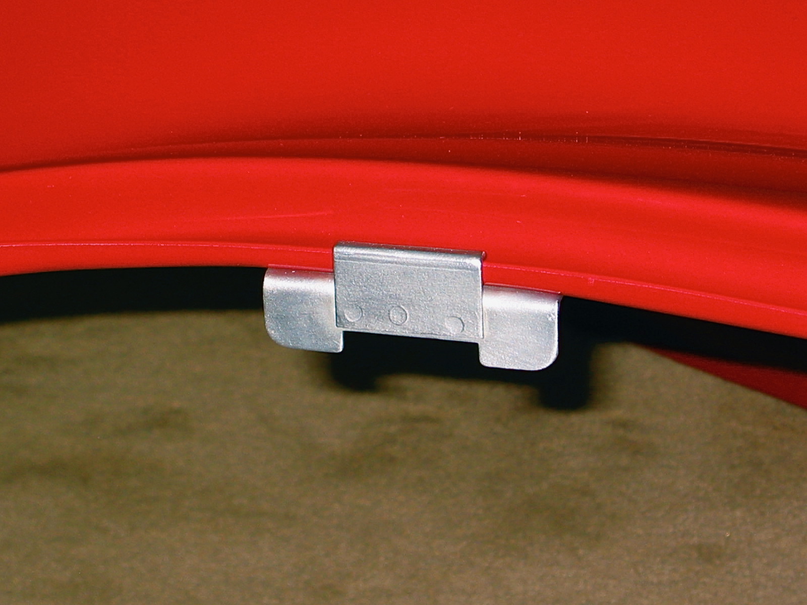
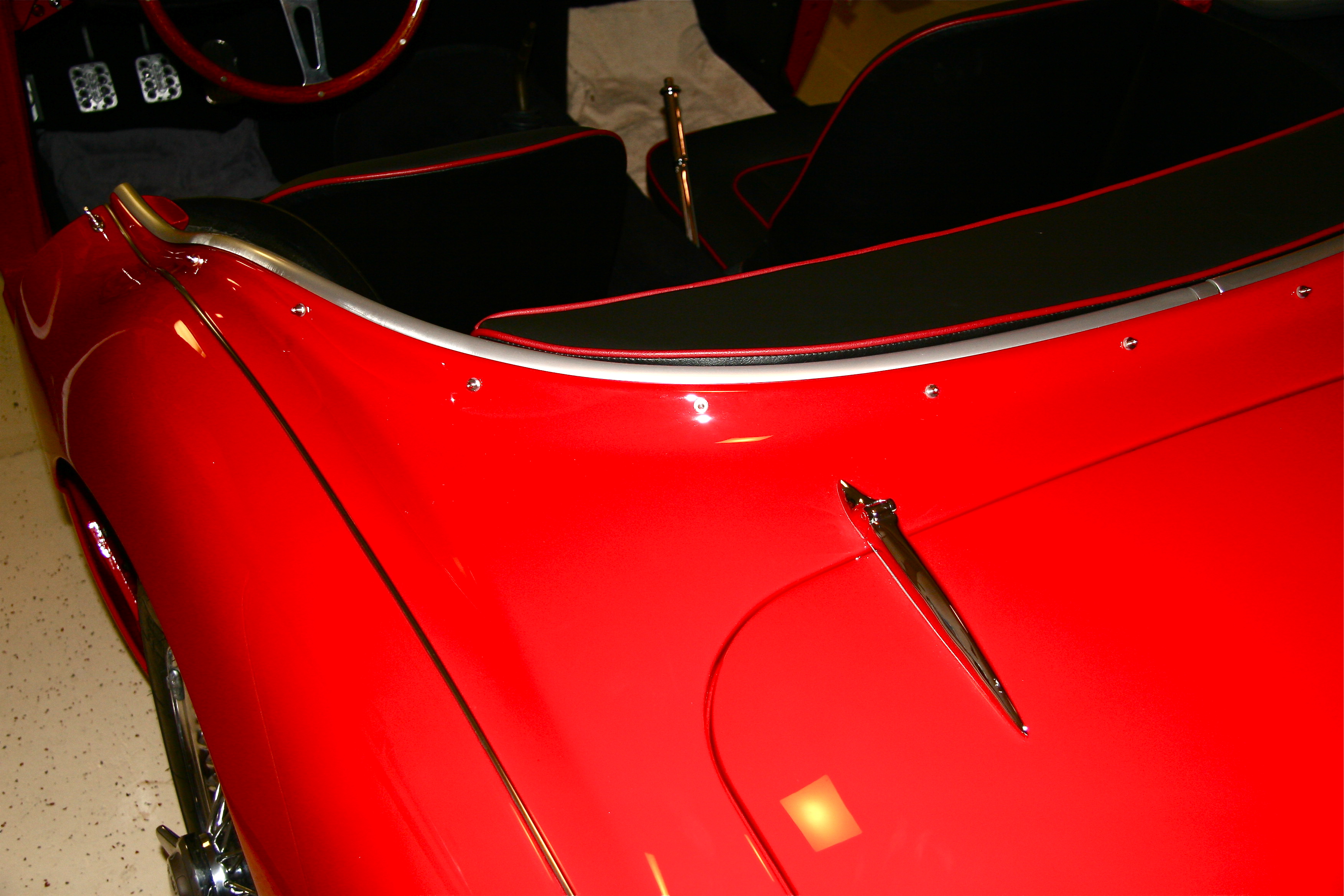
The final job for this week was the installation of the aluminum cockpit moulding on the rear shroud. I had my moulding cleaned, buffed and anodized by Ano-Brite in California. They did a fantastic job. I highly recommend them. I used some 3M strip caulk under the moulding to seal out water from the exterior.
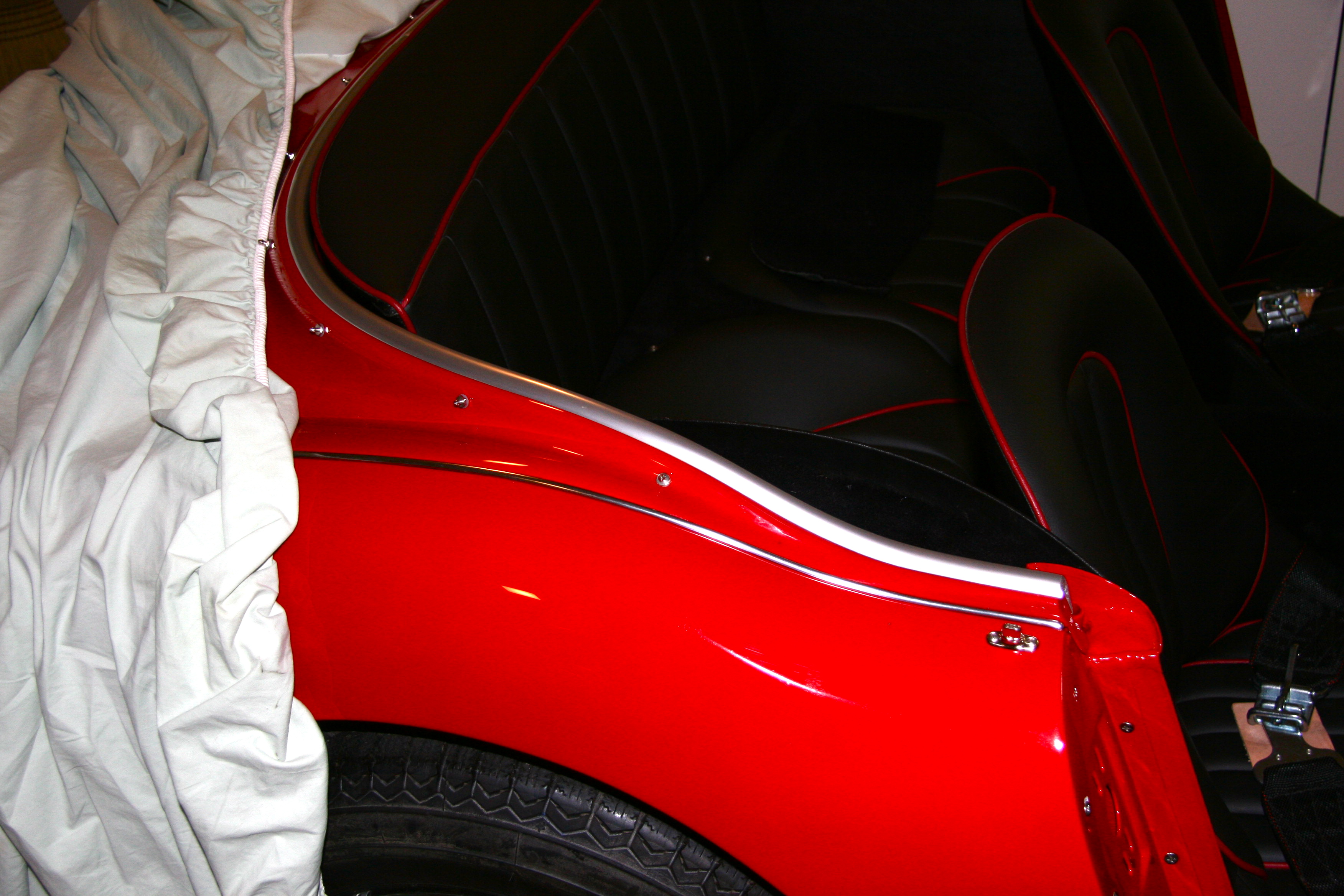
Cockpit trim 1
Cockpit trim 3