Engine Install
One of the things I wanted to accomplish with the engine clean-up was to have the exhaust header coated to reduce heat in the engine compartment and interior. I used Swain Coatings. The header came back looking great. Time will tell if the coating holds up and is effective in reducing heat.

Swain Coat Header

Swain Coat Header
I also did a general cleaning of the engine including a new paint job while the gearbox was being worked on by Jack Harper. I replaced the oil sump gasket and the rocker cover gasket, too. I tested and reinstalled the gear reduction starter. The air cleaners were cleaned and oiled with K&N products.

Clean Motor Assembly

Clean Motor Assembly
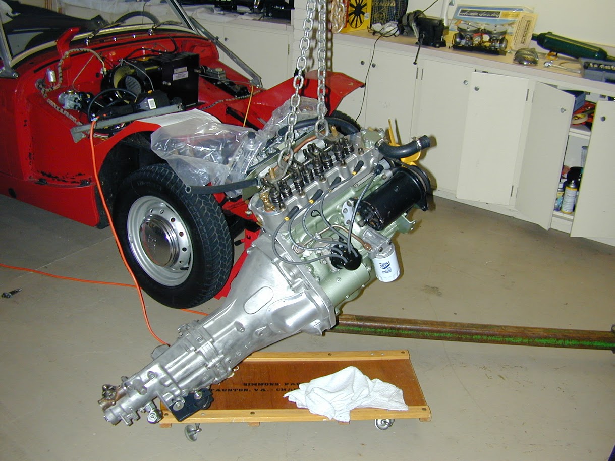
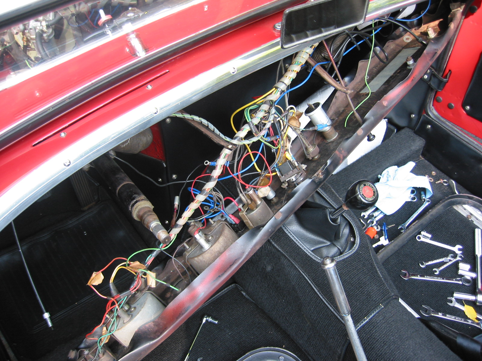
I developed the following list of items for reinstalling the engine and gearbox into the Bugeye:
Reinstalling a Bugeye Engine and Datsun 5-speed Transmission
- Grease the shaft splines on the engine and the yoke before installing the engine.
- Set the exhaust header in place so that it will be positioned to install once the engine is tightened into its mounts.
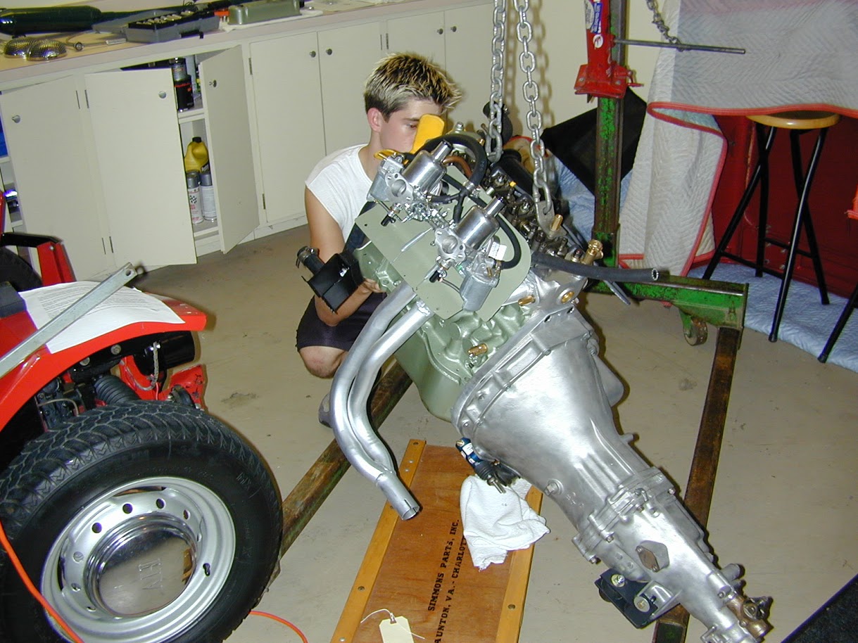
- Guide the motor into place with the lift so that the yoke on the driveshaft lines up with the transmission. If this does not work then remove the driveshaft and install after the engine and transmission are in place.
- Loosely secure the engine to the front motor mounts. The mounts themselves should be loose then tightened after all bolts/nuts are in place.
- Install the long bolts up through the crossmember into the rear transmission mount and tighten.
- Tighten the front engine mounts.
- Center the transmission in the rear mount, then push it as far to the right as possible, and tighten the transmission pad mounts on the bracket.
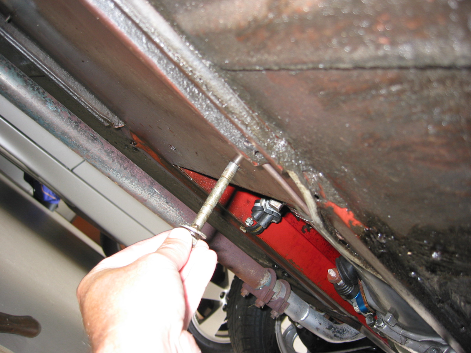
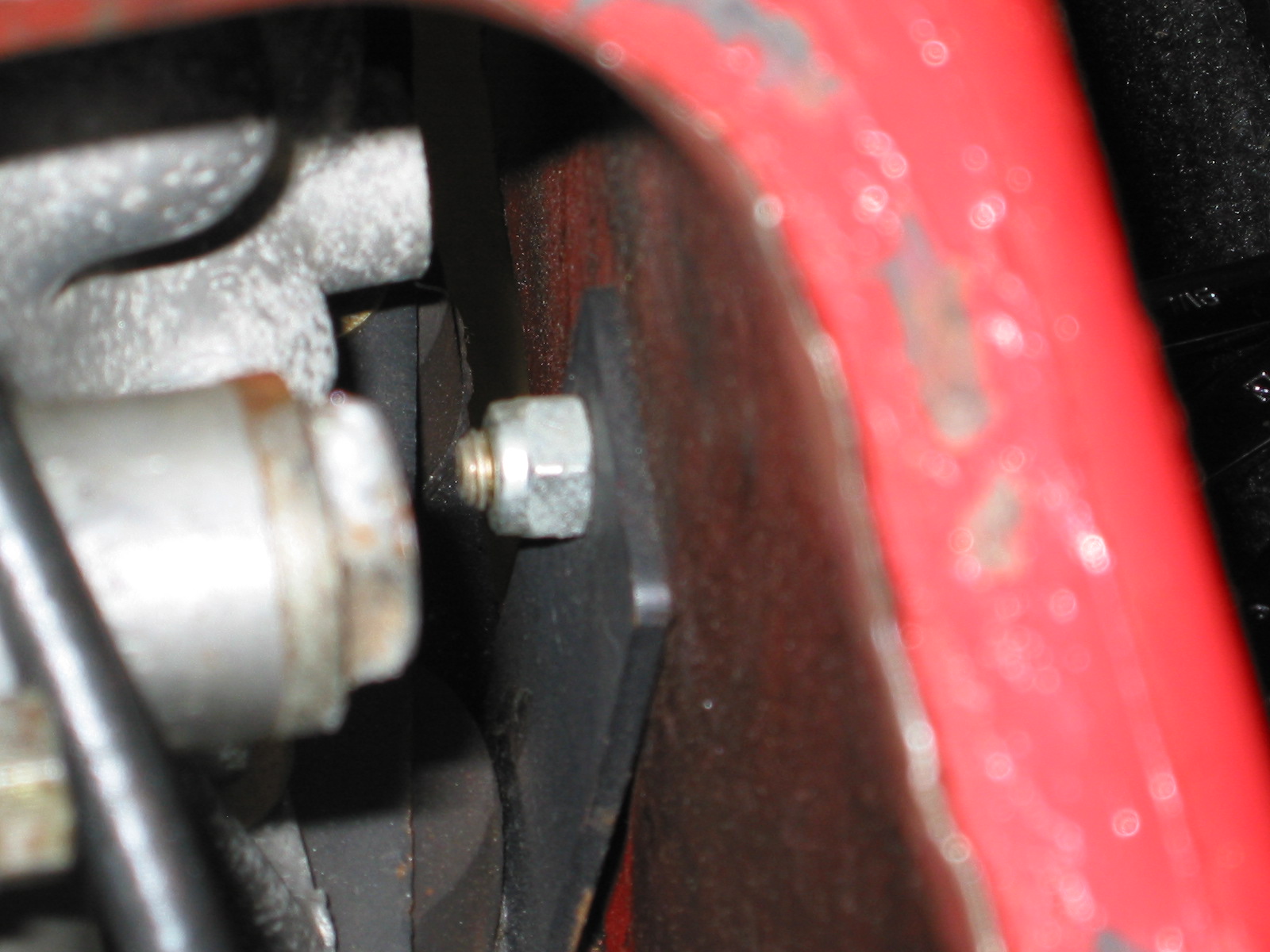
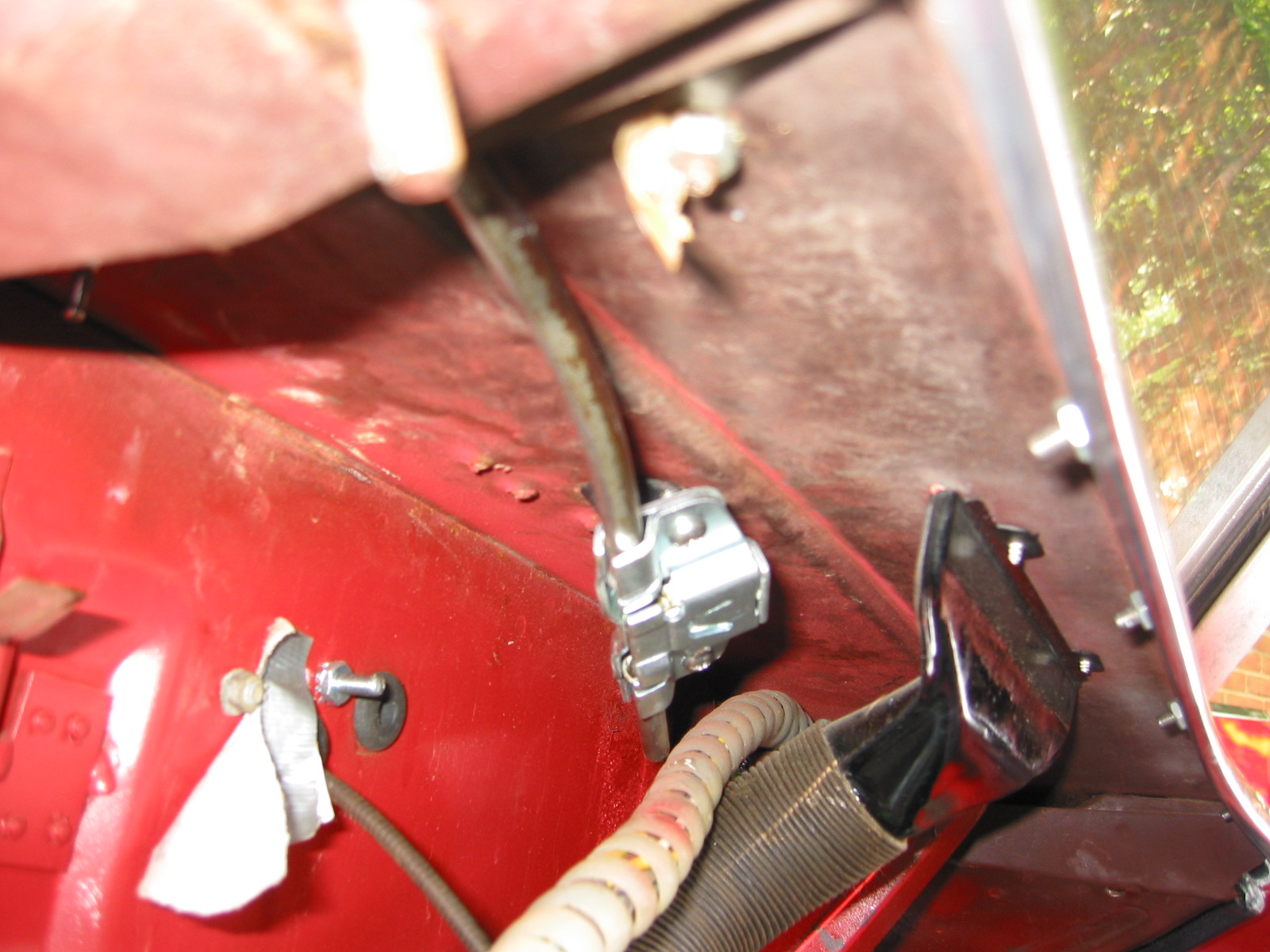
- Install the bolts in the sides of the transmission rear mounts from inside the car with the self locking nuts inside the tunnel. (Hint: tape the nuts in the wrench to make starting the threads easier.)
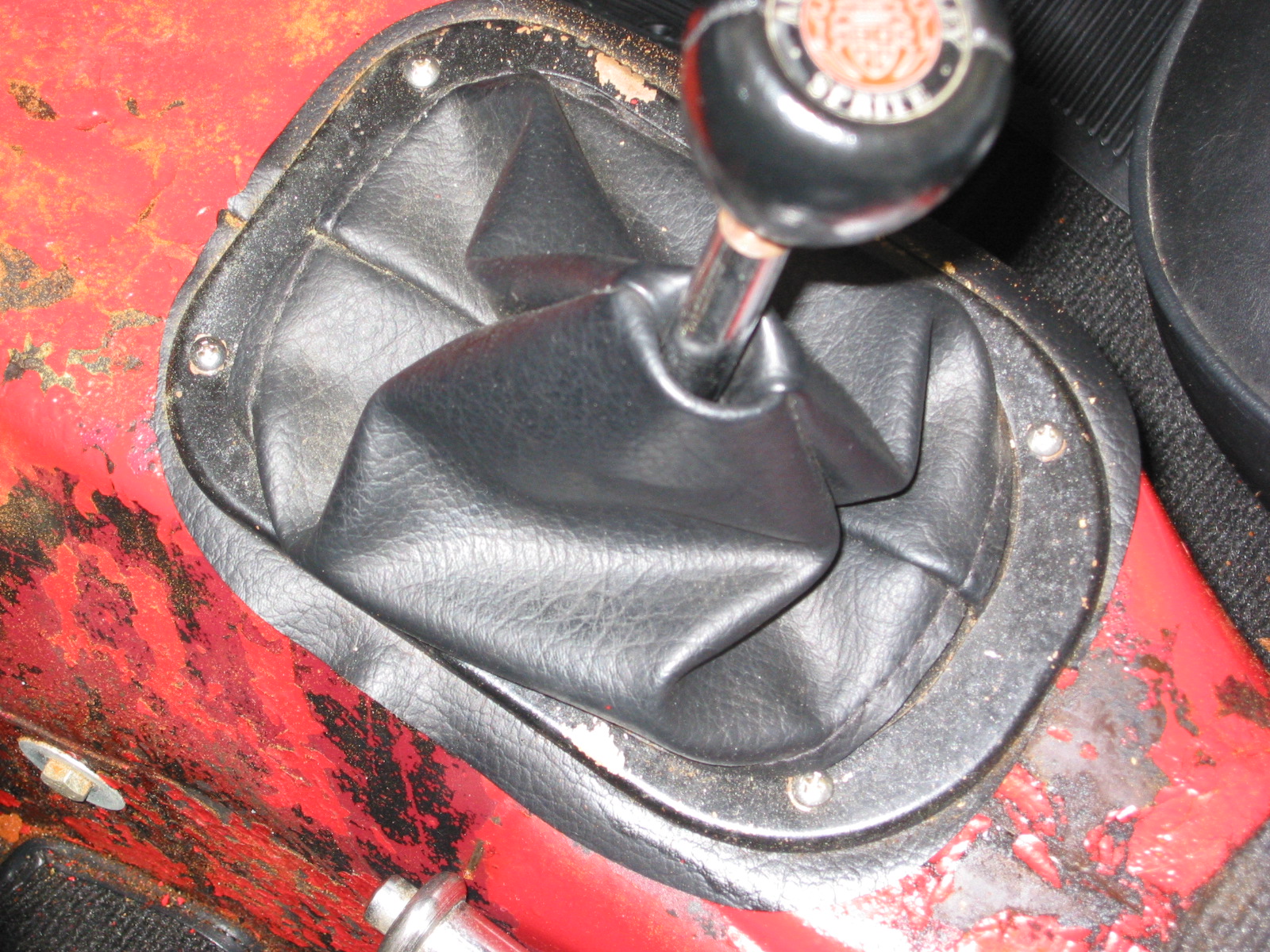
- Replace the gearshift lever.
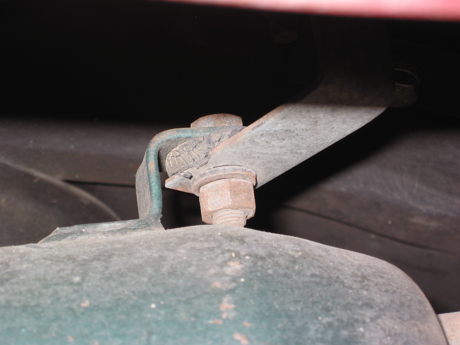
- Connect the ground strap to the frame of the car.
- Replace the rocker cover and connect the breather hose.
- Install the intake and exhaust manifolds.
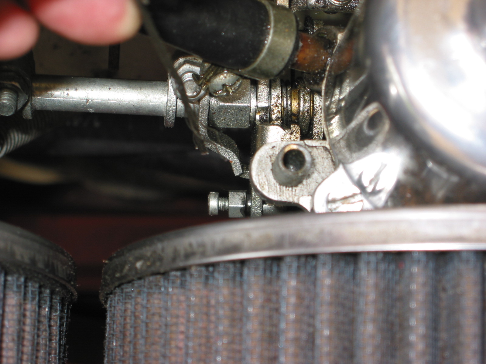
- Install heat shield and carbs.
- Connect throttle and choke cables.
- Connect breather hose.
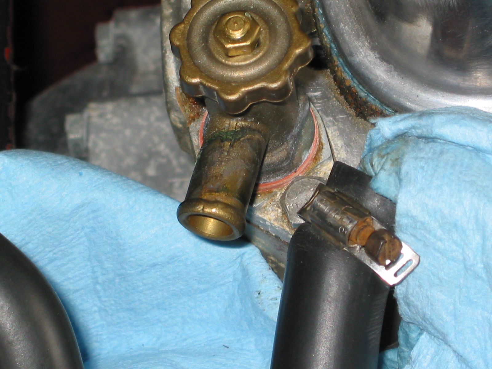
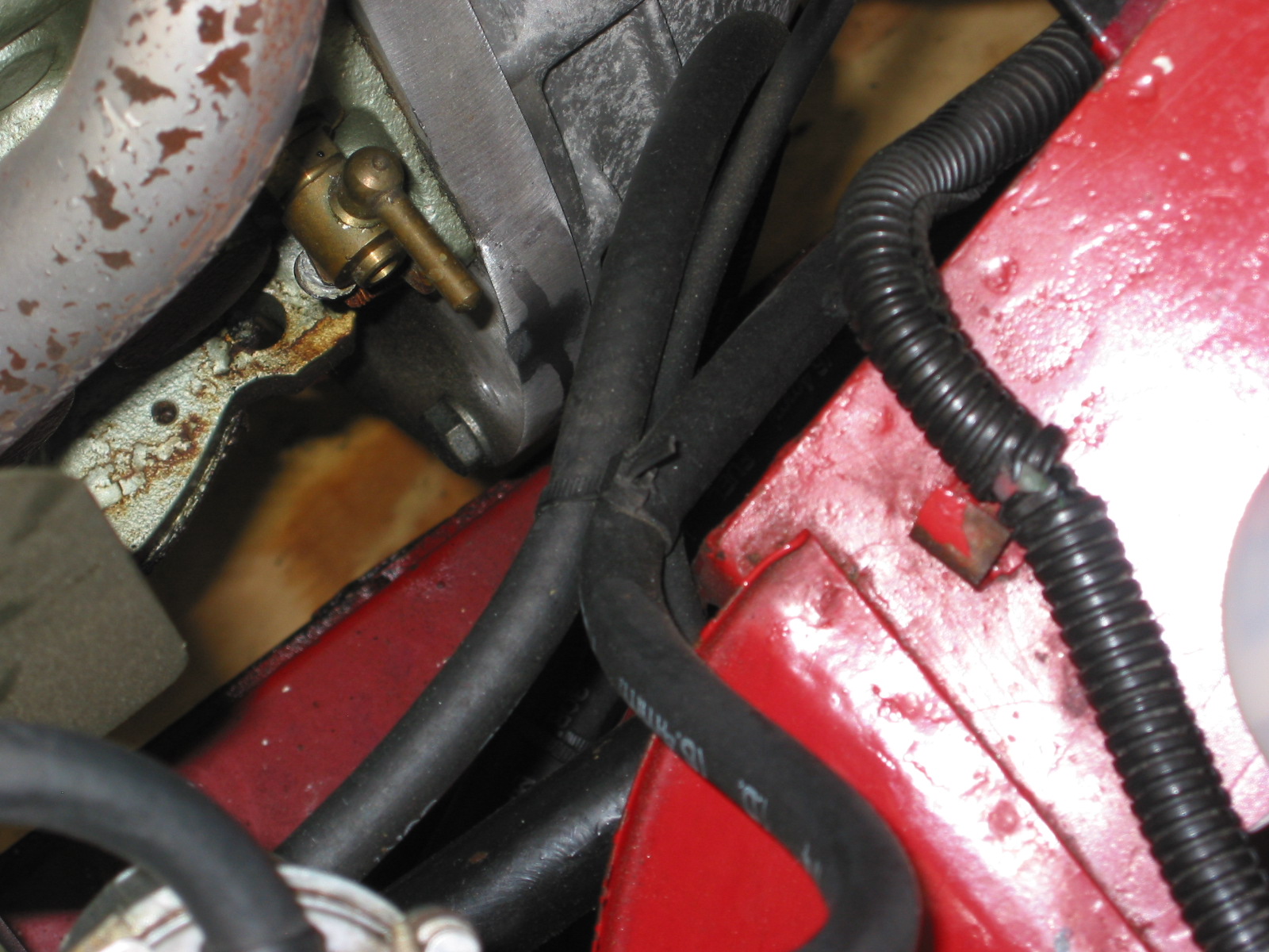
- Connect hot water hose to copper tube and connect to radiator hose. Tighten clamps. It is easier to put the clamp on the hose/copper pipe when the copper pipe clips are loose from the manifold.
- Connect the short hot water hose from the water control valve to the heater.
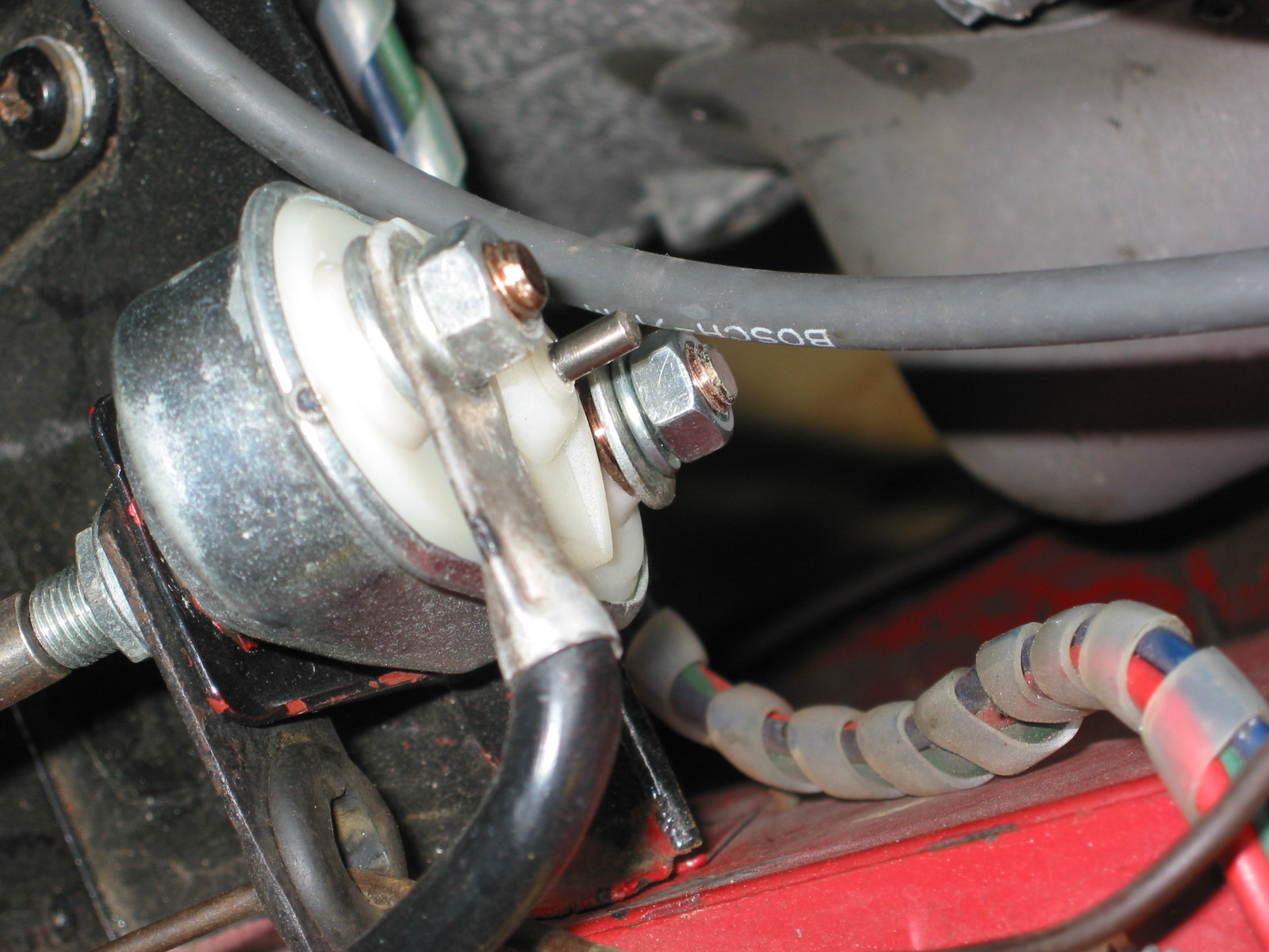
- Connect the electrical cable from the gear reduction starter to the starter solenoid.
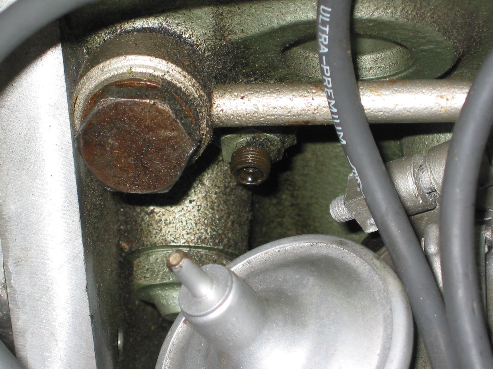
- Connect the oil pressure pipe to the fitting on the engine block by the banjo bolt.
- Reconnect the white/black line from the electronic ignition to the distributor.
- Connect the high tension line from the distributor to the coil.
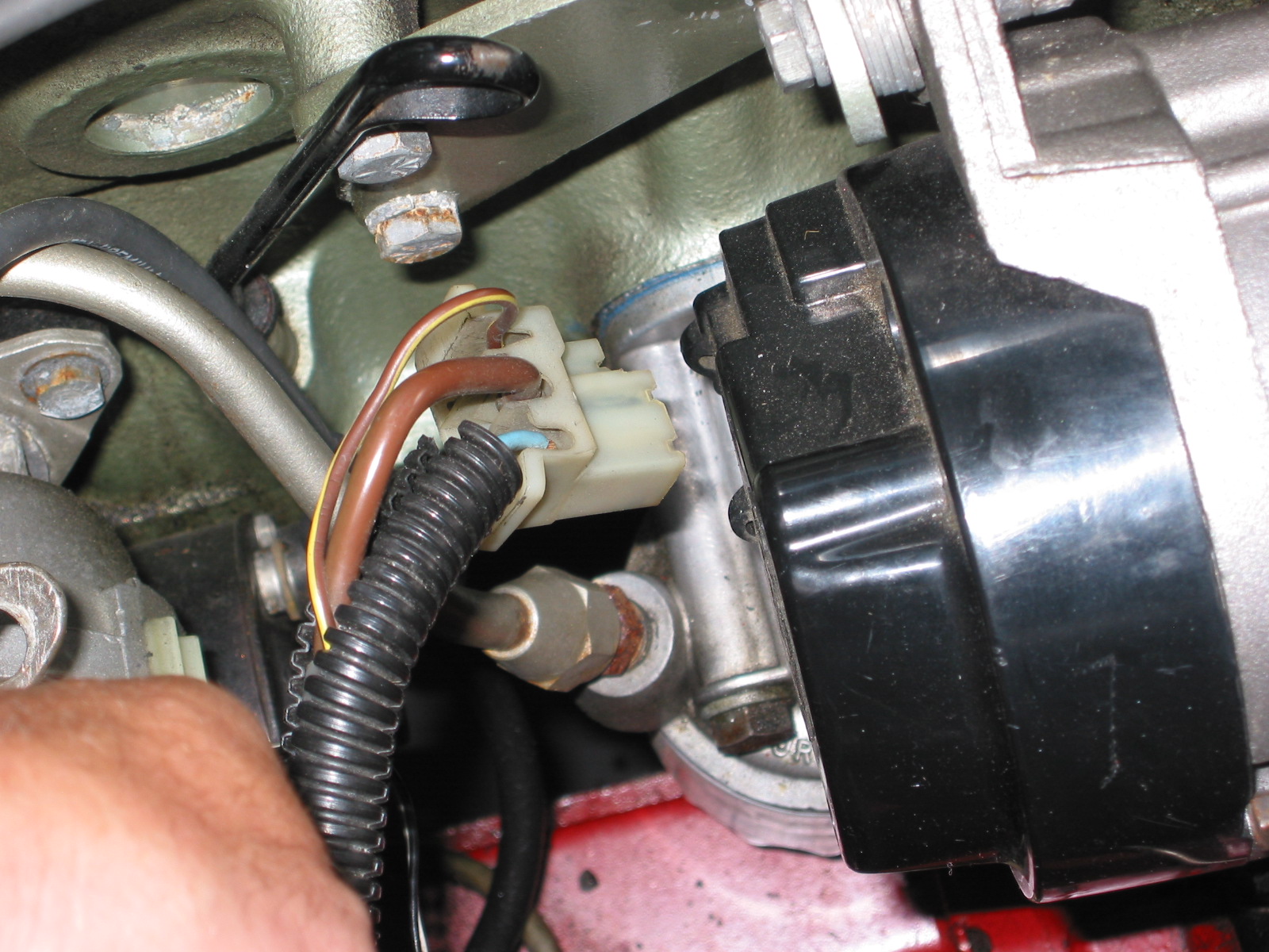
- Reconnect the plastic terminal (3 wires) to the alternator.
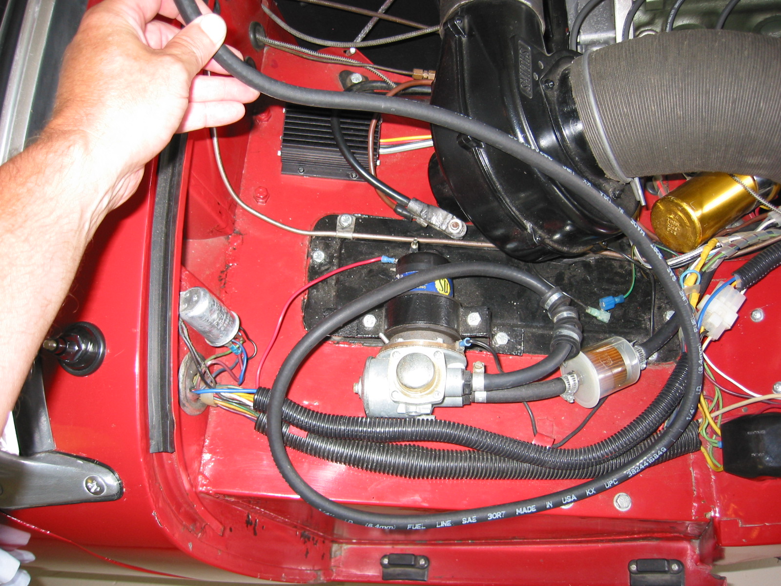
- Connect the fuel line from the fuel pump to the carbs.
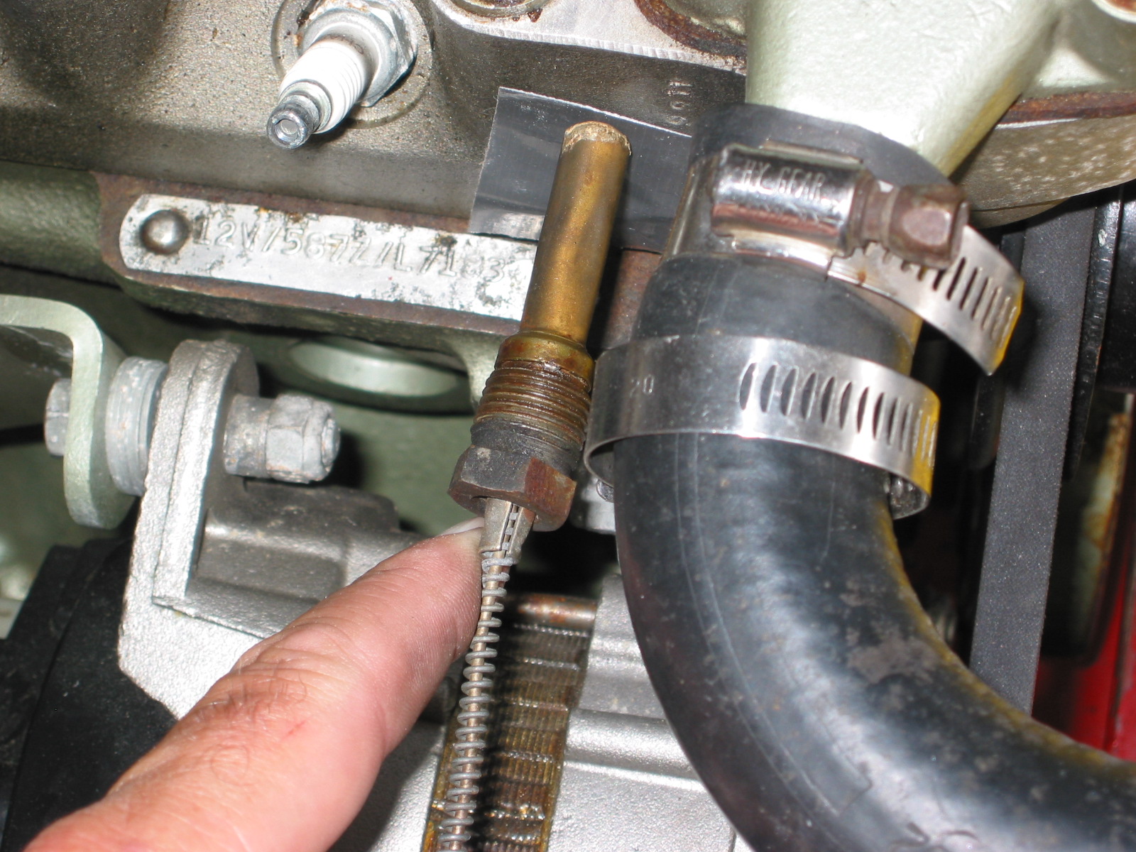
- Reattach the water temperature sensor to the engine head.
- Remove the banjo bolt where the oil line exits the rear of the block. Pour motor oil down the hole in the block to prime the oil pump. Reinstall the bolt.
- Remove the oil filter and pour it full of motor oil and reinstall.
- Fill engine with oil – Castrol GTX 10W-40.
- Fill the gearbox with Gear lube – Redline MT90. 2 1/4 pints. Use long clear plastic tube. Try pump.
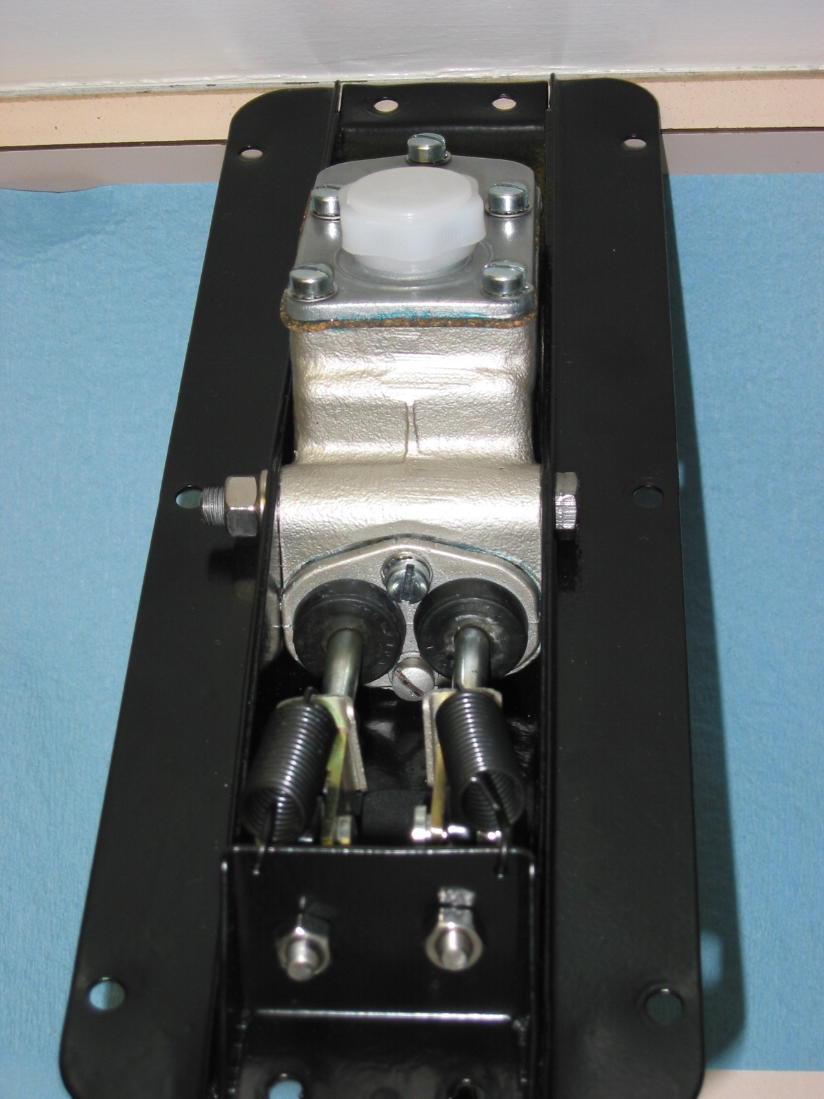
- Connect the stainless steel flex line from the master cylinder to the slave cylinder.
- Bleed the clutch slave cylinder. (See Page 9 of Rivergate’s manual)
- Install radiator and fill with 50% coolant and 50% distilled water.
- Fix the carb drain lines to the mounting clamp at the lower rear of the engine compartment.
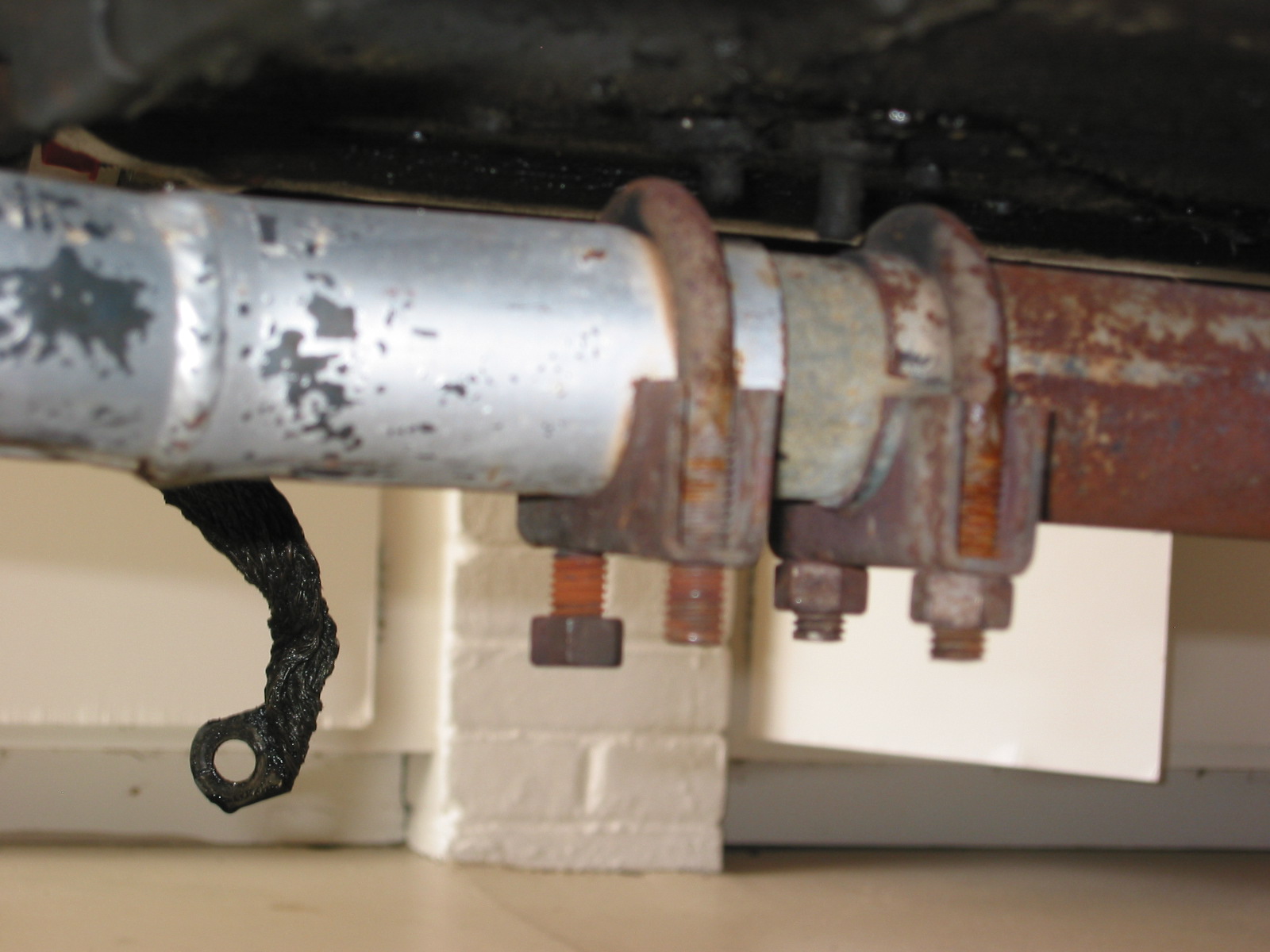
- Insert the 1 ½” connecter pipe (with sealant) for the exhaust system into the header pipe.
- Install the exhaust and muffler assembly.
- Tighten clamps on the exhaust connecter pipe.
- Reconnect the battery cables.
- When ready to start the engine, pull the spark plugs and spin the engine with the starter until the oil pressure goes up to normal on the pressure gauge, and stays.
- Check for any oil, coolant and fuel leaks.
- Reinstall the spark plugs and start engine.
- If engine does not start turn distributor 180 and try again!
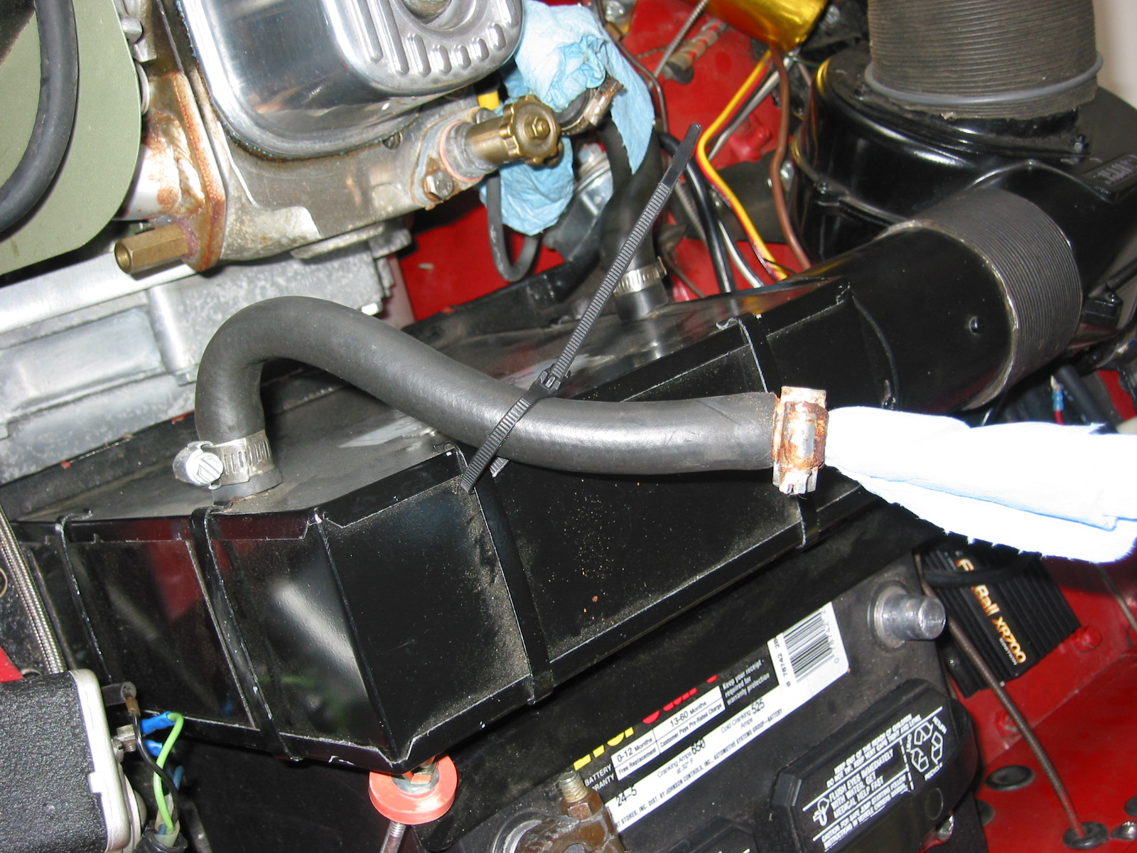
- Install 4” fresh air heater hose and clamp.
- Install the leather shifter cover and surround.
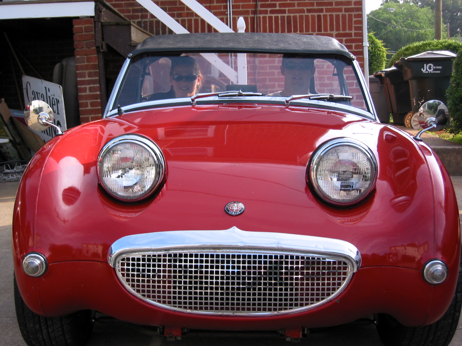
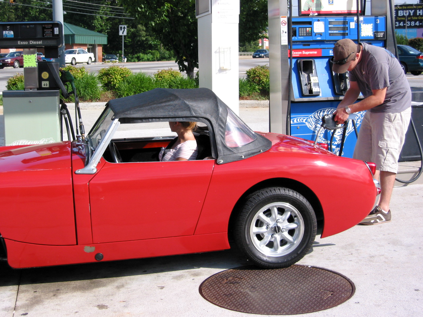
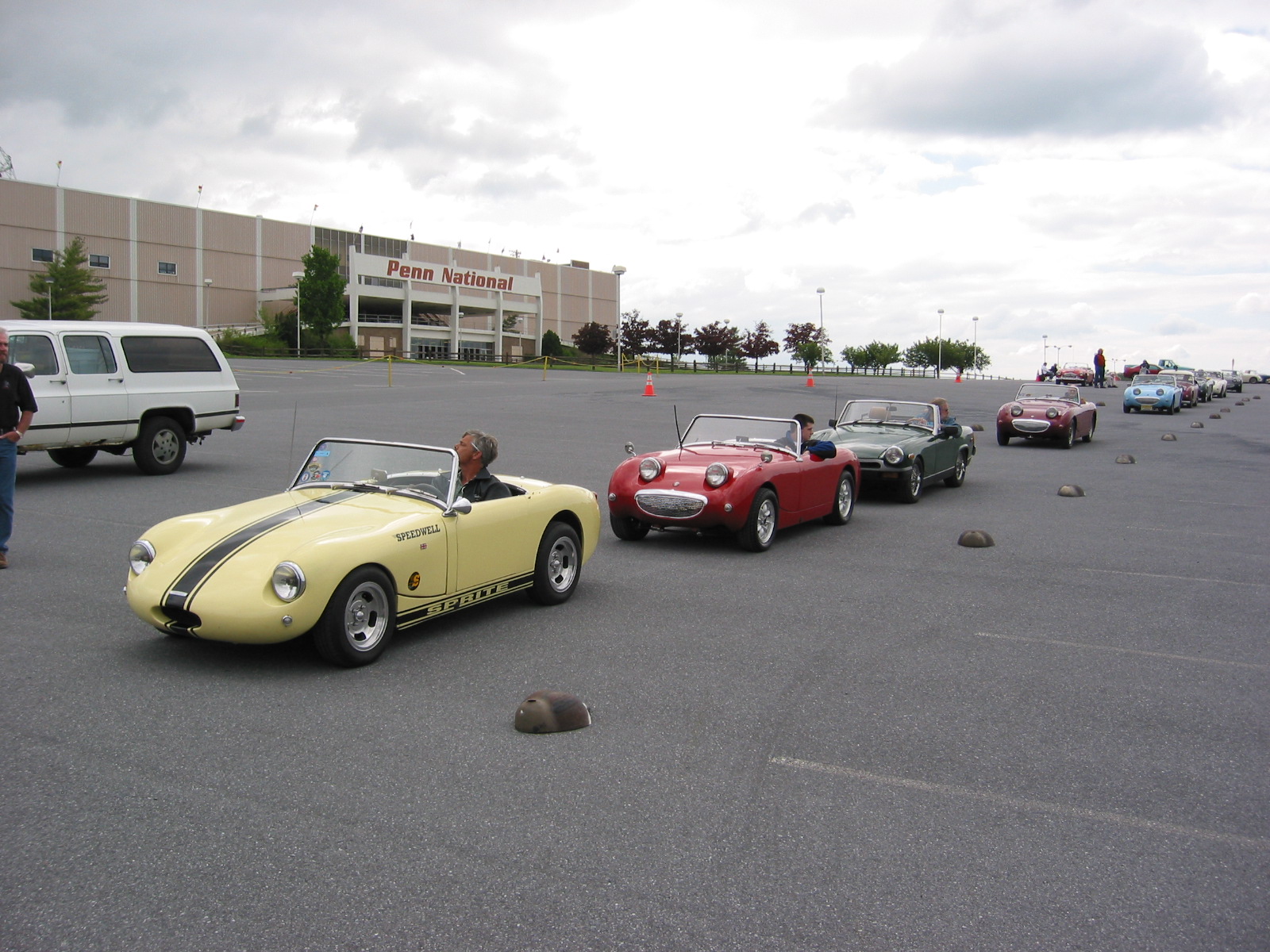
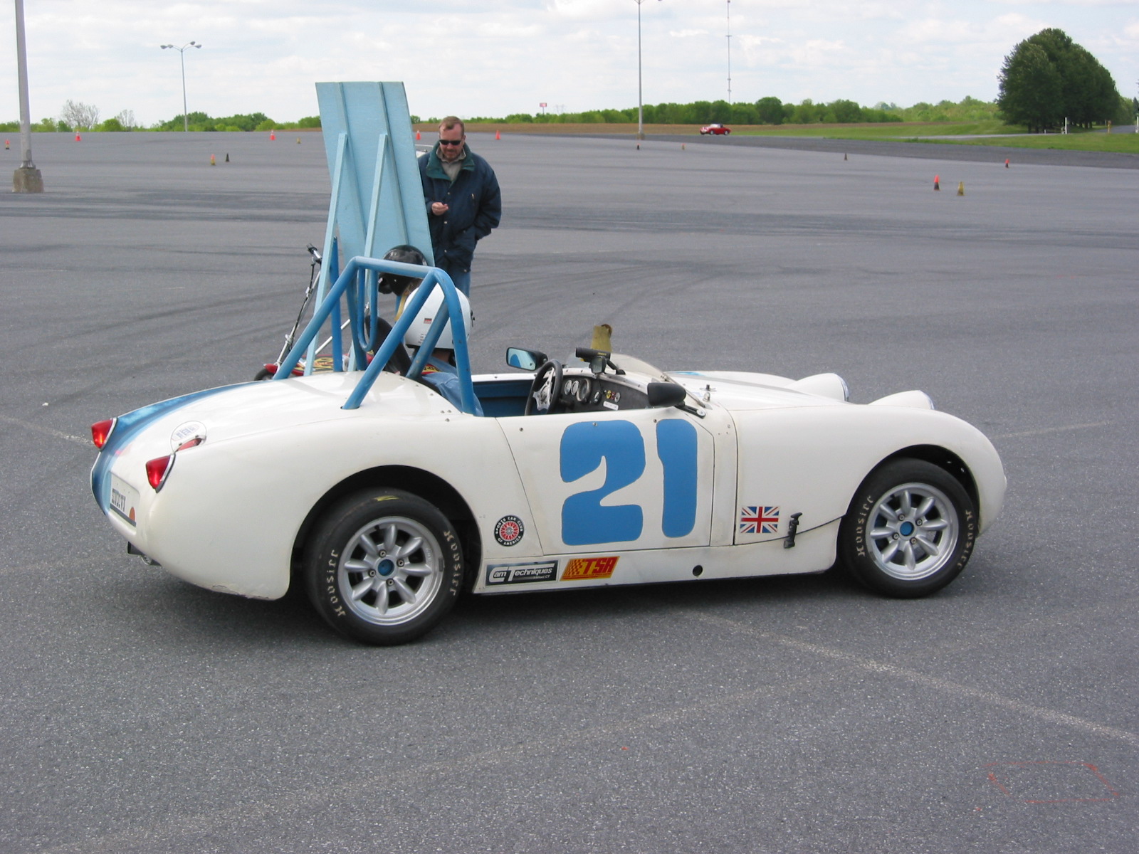
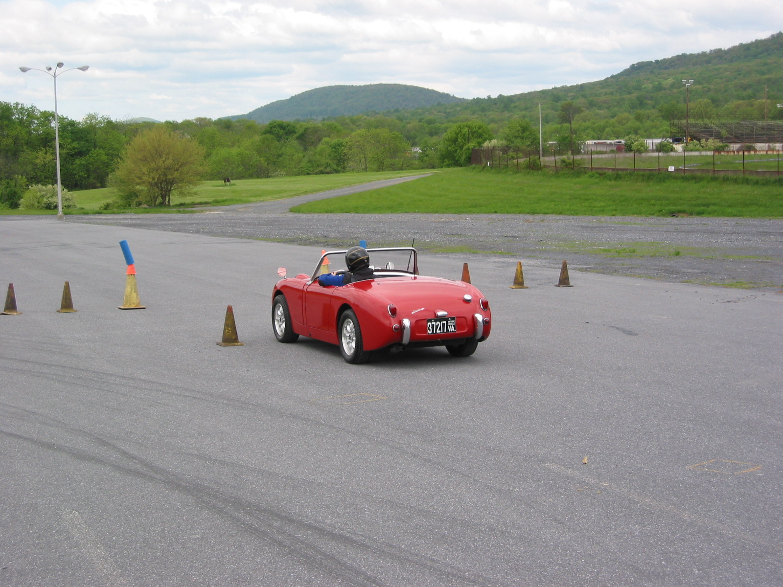
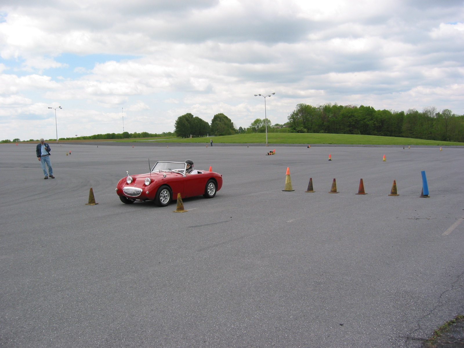
Start It Up And Have Some Fun!
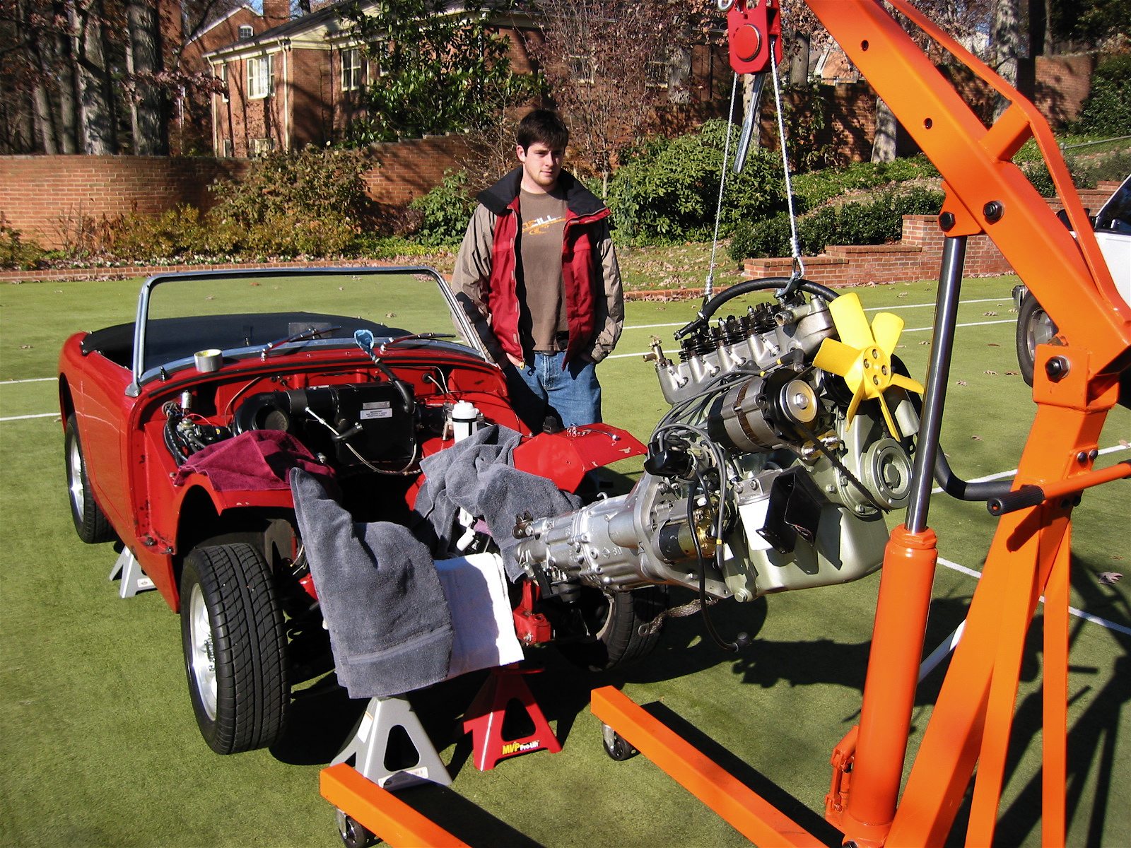
I Know It Fits!
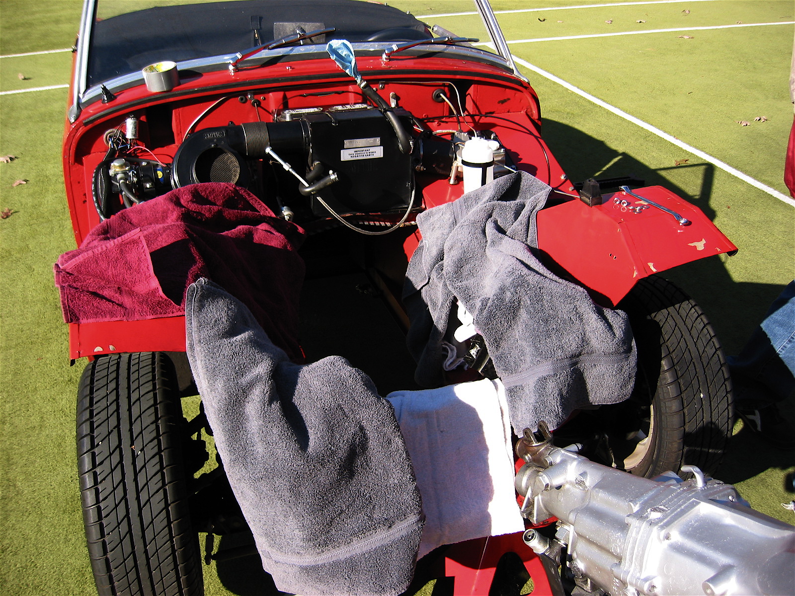
Motor Protection!

Engine Install