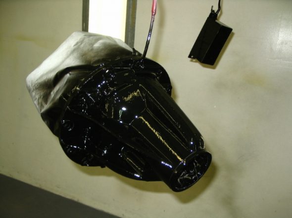
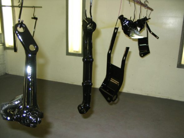
Chapter 41 Restoration Assembly, Week Eight 2/5/2007

With the steering behind me, I thought it was time to install more of my electrical accessory items. Most of the bits fasten behind the dash in one form or fashion, so I wanted to get them all located, mounted and wired before the dash fascia was installed.

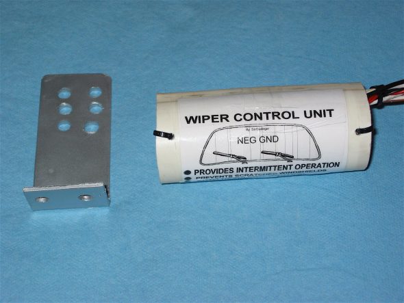
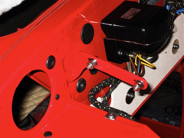
Intermittent wiper control – The big Healey came standard with a one speed (slow) windscreen wiper motor. Ed Esslinger, a member of the Tiger United Club designed and built a wiper control unit to provide intermittent wiping of the windscreen and made them available for sale. [email protected]  334-774-5155. I purchased the kit to install in the Bloody Beast. Ed’s directions are detailed and easily followed. Intermittent Wiper Control

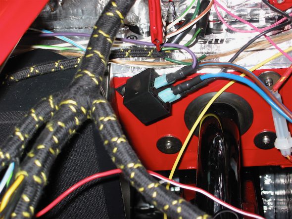
Ed provided for a mechanism to connect the wiper control with the lights so that the lights are on when the wipers are working – now a requirement in many states. The wiring from the relay (shown to the right) connects to the control unit, ground, and to the lighting switch. Including an optional rectifier diode between the S1 and S2 terminals on the switch provides for operational parking and tailights while the wipers are working as well.

Intermittent wiper bracket

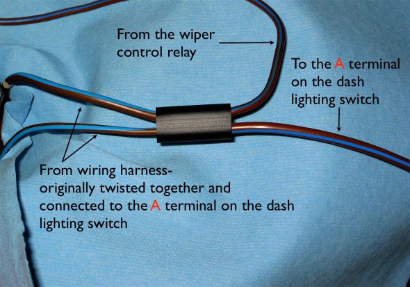
I used a double wiring connector to join the two brown/blue wires that originally linked to the A terminal on the switch with the brown wire from the relay, and then ran one brown wire to the A terminal on the light switch.

Wiper/Lighting Connection

Intermittent wiper relay2

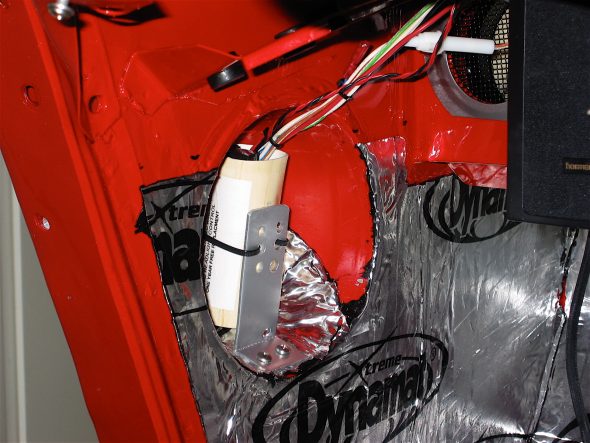
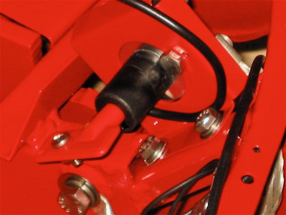
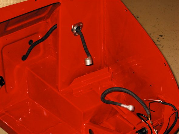
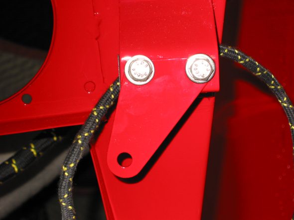
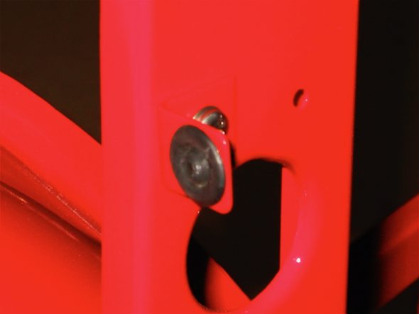
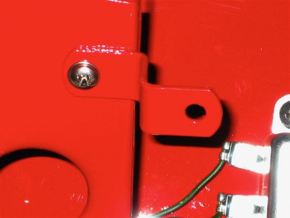
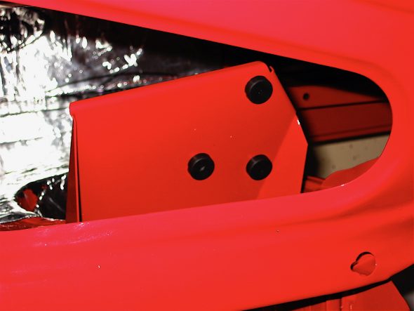
I had Martin Jansen install headlight buckets in the holes in the scuttle side panel assembly to use for mounting speakers, but decided against using them for that purpose, but they make a nice “hiding place,” so I decided to use the one on the left side of the car to “hide” the control unit for the intermittent wiper control module. I made a little bracket to secure it and then mounted the assembly with two stainless self tapping screws into the bottom of the headlight bucket.

Intermittent wiper assembly 2

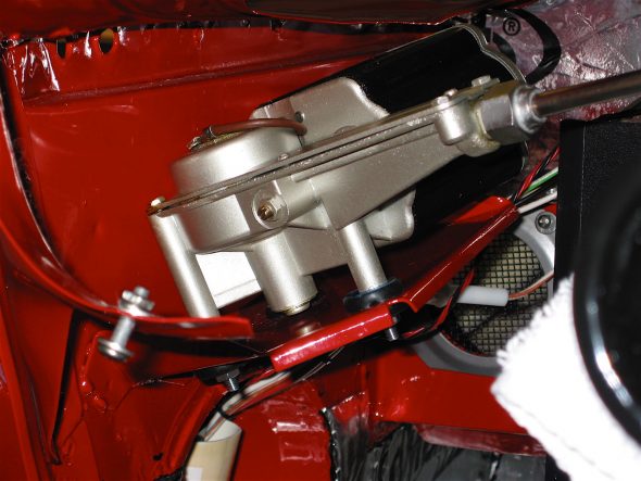
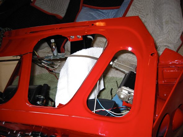
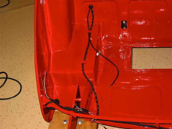
The wiper motor installed fairly easily. It mounts on three posts with rubber buffers. I temporarily tied the rod to the scuttle with plastic ties.

Wiper motor installed 9

Wiper motor installed 2

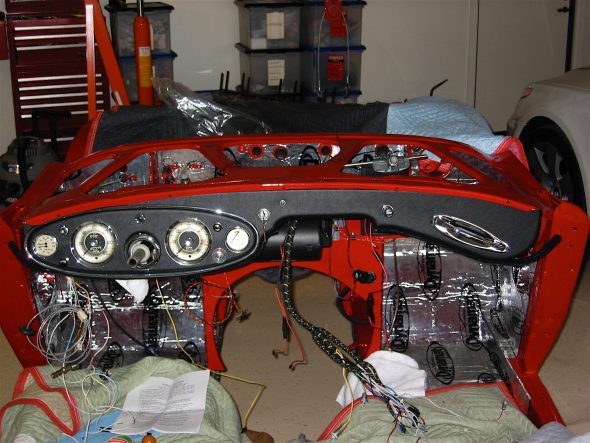
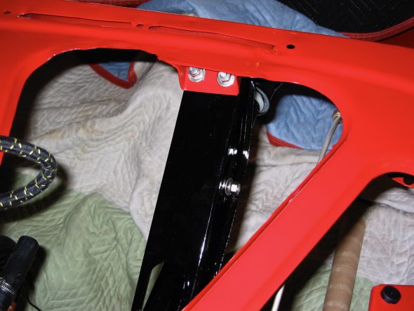
Next came the dash fascia. I mounted it with the four #10 machine screws on the outside edges and one through the dash in the middle. I held off on the two support braces until after I finish all electrical and heater work behind the dash.

dash fascia 2

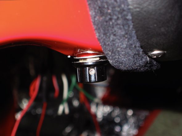
Wiper Rheostat

Chapter 40 Restoration Assembly, Week Seven 1/29/2007

Work on the Bloody Beast was restricted to the weekend. Attention was given to the steering components of the car.

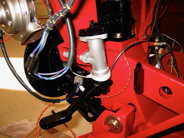
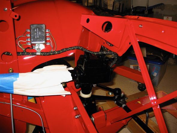
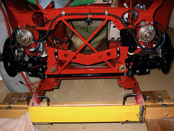
The steering idler and the steering box, along with the aluminum spacers were installed and penrite oil was used to fill the idler. The steering box will be filled later. The tie rods and the cross rod were also installed to the steering levers and the cross rod was adjusted to bring the front wheels into eye-ball (not measured) alignment. 

Steering Idler 1

Steering Box 3

Steering Assembly

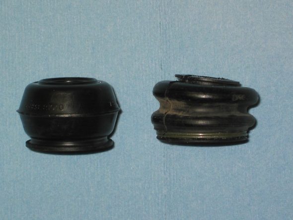
The rubber ball joint dust covers that came with the new tie rods were cracking even before they were on the car. Others suggested that Hyundai rubber ball joint dust covers, part # 56828-21010 would fit and were of higher quality so I gave them a try. Korean parts on a sixties british car – go figure.

Tie Rod Dust Seals 2

The steering bracket and steering column support clamp were affixed. The clamp was installed in the third hole from the top of the bracket as it was in the original assembly. All mounting bolts were left loose until the dash fascia is installed to determine proper alignment through the steering shaft hole in the dash.

Steering Bracket 2

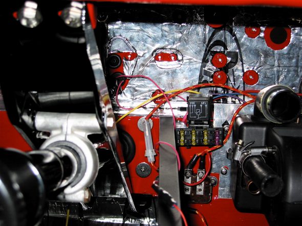
The radiator brackets were installed and then attention was turned to completing more of the electrical work under the dash. To protect accessory electrical functions I am adding (modern heater, accessory power supply, sound system, interior lighting, etc.), I added a supplementary fuse block mounted on the air chamber behind the dash. It was available from Victoria British, Accessory Fuse Block.pdf Painless Performance Products, #70103 Cirkit Boss/3 Circuit. A wiring diagram is available on the .pdf link. I used the pink wire to the main fuse block on the firewall, the yellow wire for the 2 speed heater, the blue wire for the amplifier, and the purple wire for the accessory power supply (cigar lighter).

Accessory Fuse Panel

Chapter 39 Restoration Assembly, Week Six 1/22/2007

Absolutely nothing accomplished this week other than receiving my rebuilt oil pump. Jack Brashear, fellow Healey owner, had new shafts, and gears put in my pump. I just decided I would rather rebuild the original than mess with a new one. We will see how it works out. Special thanks to Jack! 

Chapter 38 Restoration Assembly, Week Five 1/15/2007

The schedule of the week did not afford much time for car restoration. In fact, nothing was accomplished on the car throughout the work week! Saturday did permit a resumption of spanner work.

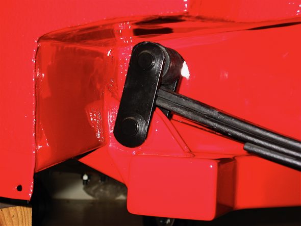
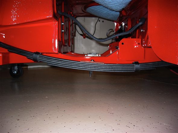
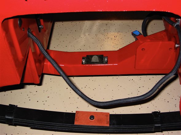
The rear leaf springs are an interesting and somewhat costly story. I had ordered new leaf springs and hardware from British Car Specialists to install on the car. I noticed that Martin Jansen had not installed the long grease fittings on the rear bushing mount location as was appropriate for the early 3000s, so I gave him a call to find out what I was to do and Martin told me that his frame was designed for the later BJ8 rear leaf spring set-up, and he recommended a custom made spring that he could provide that was much better suited to the frame. He indicated that his frame would “beat-to-death” the original BT7 springs. I had already taken apart the springs from BCS, installed teflon tape between leaves and repainted each leaf and then reassembled the springs with new shackle hardware. Oh well, a few wasted dollars.

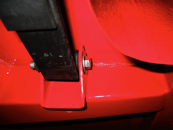
I ordered Martin’s 5 leaf springs which do use the phase 2 BJ8 shackles. Because the assembly pin in the center of the leaves is a bit larger than the BT7 stock springs it was necessary to drill-out the center hole in the lower spring plate to 7/16.” The BJ8 mounting uses 8 rubber bushes in the rear rather than the steel bush of the BT7 variant. Everything installed nicely.

Leaf Spring Rear Shackle

Leaf Spring front Mount

Leaf Spring

Rear Axle pads

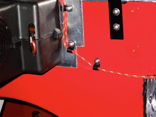
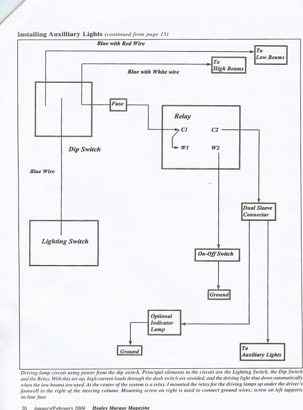
I then returned to routing the driving light wiring from the relay under the dash to the front of the vehicle. I used an orange/yellow fibre-covered wire from British Wiring that is supposed to be correct, but I didn’t verify. The wire from terminal C2 on the relay was routed over the heater and below the corner of the parcel tray and then out through a rubber grommet to the engine bay. The wire was then routed through the harness mounting clips to the front.

I used an article from Healey Marque Magazine, January/February 2004 by John Trifari on how to install auxiliary lighting in a BJ8. John provided excellent guidance. Details of the wiring connections are provided in this summary. I did install an optional indicator light with one terminal to ground and the other wired to the C2 terminal on the relay.AH BT7 Driving Lights.pdf

Driving Light Wiring 1

Driving Light Wiring 2

Driving Light Wiring Schematic

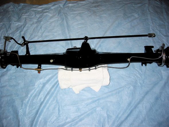
I am replacing the stock drum brakes in the rear of the car with the disc brake conversion kit sold by Cape International. The kit provides for a parking brake function by using small calipers ancillary to the Jaguar calipers. It also includes the brake rotors, custom brackets for the calipers, brake pads and mounting hardware. A little trimming of the flange on the axle is required, but otherwise it is basically a bolt on process. Cape Int. Disc Brake Conversion.pdf

Handbrake hardware

Handbrake lever 1

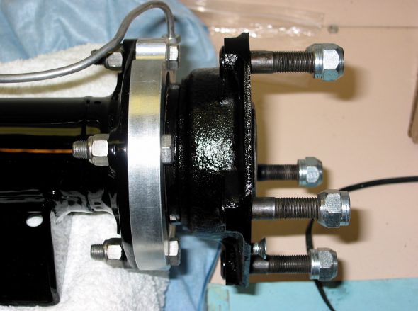
I cannot fully assemble the rear axle with brakes until Bruce Phillips at Healey Surgeons finishes the installation of my 3.55 Lempert rear differential. However, I began the process by first installing the rear disc brake caliper brackets on the axle, followed by the rear hubs with new bearings and seals. I had the bearings and seals in the hubs from my pre-assembly process of more than a year ago. To make the hub installation onto the axle an easy job, Mike Jennings, in the August 2005 Healey Marque Magazine, recommended wrapping the assembled hub in aluminum foil and heating it in the oven at 250 degrees for about 20 minutes. He suggested that the hub could then simply be pushed onto the axle by hand. I tried it and it worked as advertised! No tools required.

Rear Caliper Bracket & Hub

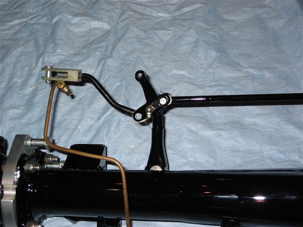
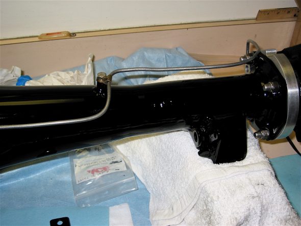
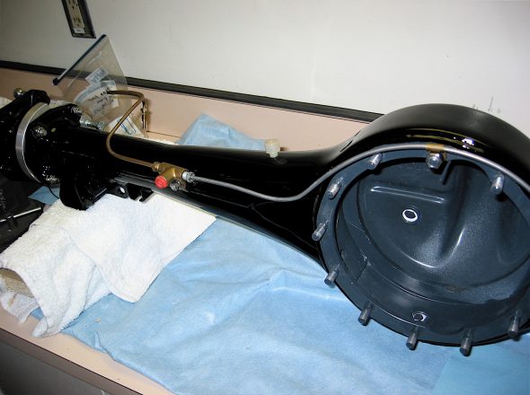
The rear hydraulic lines were then mounted on the axle as well as the handbrake hardware including the balance lever, its mounting bracket and the cross rod. All of this will need to be adjusted after the rear differential, half shafts, rotors, hubs, and calipers are installed.

Brake Line to Left Rear

Brake Line to Right Rear

Chapter 37 Restoration Assembly, Week Four 1/8/2007

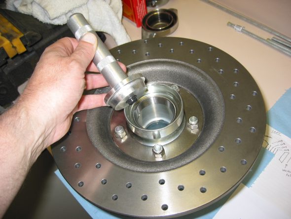
The front hub assemblies were the next parts to tackle. I had previously assembled new hubs to new drilled rotors. I fastened the rotor disk to the hub extension with 5 nylock nuts. Placed bearing races in the freezer so they would be easier to install in the front hub extensions. Then inserted inside bearing race with proper driver with the careful application of a hammer!, being careful to keep the race/driver straight. Turned the hub over and did the same procedure with the outside bearing race.

Bearing Race Install

Front Hub Bearings – Norman Nock and Doug Reid Doug Reid’s Front Wheel Bearings.pdf have produced some pieces that were very helpful for this process. I followed directions from Bruce at Healey Surgeons and put 90 weight oil on the inner bearing and offered it up to the spindle. The oil provided protection from damage due to the bearing running dry but at the same time, not give a false reading when trying to shim the bearings.

I then placed the spacer (cone) on the spindle followed by the hub extension. I then put an oil filled outer bearing on the axle followed by the tab washer and castle nut. The seal and shims were NOT added at this stage. The nut was tightened down to seat everything and then the works were disassembled. It can be difficult to get the outer bearing and the tab washer off – I used a magnet that worked quite well.

I then put the inner bearings, the spacer and selected shims on the axle. Starting with the thickest one .030, then .010, .050, .030, ( one of each ). I then put the hub extension on the axle followed by the outer bearing, tab washer and nut. I tightened to 40 lbs of torque and determined if one of the castle nut slots lined up with the hole in the axle for the split pin. I took care that the shims were all the way up on the shoulder of the spindle axle so that they did not get mangled when the nut was tightened. The final proper adjustment is correct when you can tighten on the nut and the wheel does not show any reduction in ease of turning with no play.

Bruce indicated that if the rotor drags when you tighten the castle nut, then you need to add shims. If it is to loose, you need to remove the shims. When it is correct, re-tighten to the correct specs. At this point, the hub should be turning freely, with no end float and no pre-load. This was a trial and error process and took a while to complete.

Once I was satisfied that I had the bearings set up correctly, I removed everything, keeping careful track of the shims! I then packed the wheel bearings with wheel bearing grease and installed the front seal. The seal has the spring facing the bearings. I then placed the spacer in the hub extension and bearings in first, and then reassembled unit.

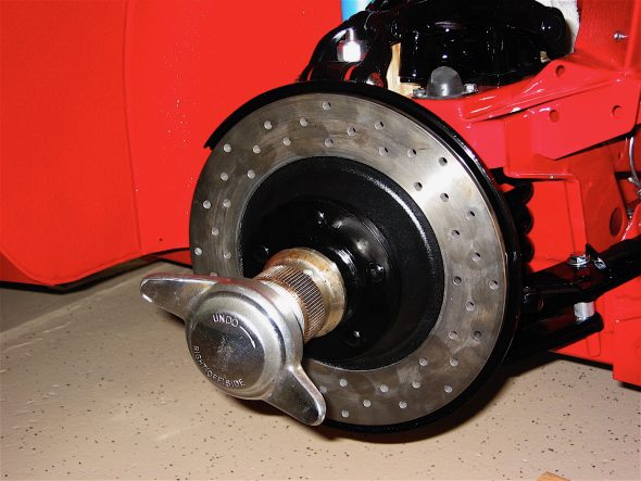
I torqued the nut to the 40-70 lb setting, lining up the hole in the axle with the nut and placed the split pin through the hole in the spindle axle, and then pulled one tab of the pin forward and bent it back over the axle end. I then pushed the grease cap on to the axle ( do not fill it with grease) and gave it a tap with a drift.

Rotor and Hub Install

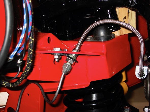
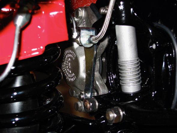
The time has come to install the front brake calipers, the hose brackets and the brake pads. The calipers mount through the brake dust shield and into the swivel axle. My calipers were rebuilt by Healey Surgeons. I used stainless steel flexible brake lines rather than the stock rubber lines.

SS Brake Line RH 2


Brake Caliper

Mintex pads, MGB 520, were used initially, although I may switch to “greenies.” Shims were used between the pads and the pistons with an application of Permatex Ultra Disc Brake Caliper Lube #24110. All hose and pipe fittings were checked and tightened with teflon tape used on all threads.

I converted the overdrive relay into a relay for the driving lights. The image to the right illustrates the mounting location, again, using nutserts.

Driving light relay 1

Chapter 36 Restoration Assembly, Week Three 1/1/2007

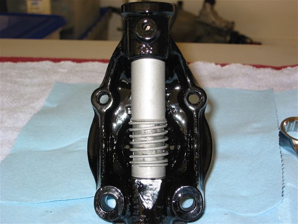
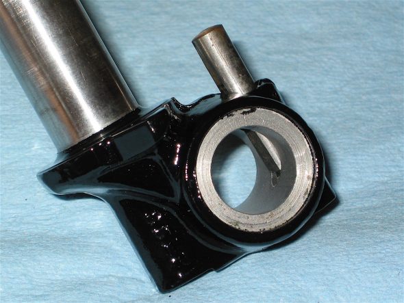
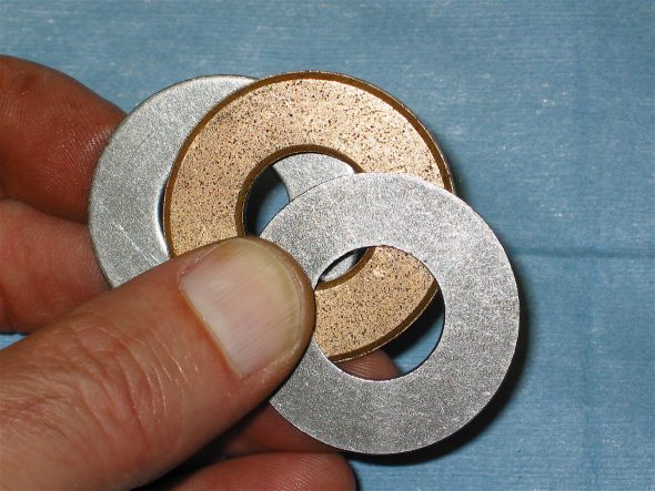
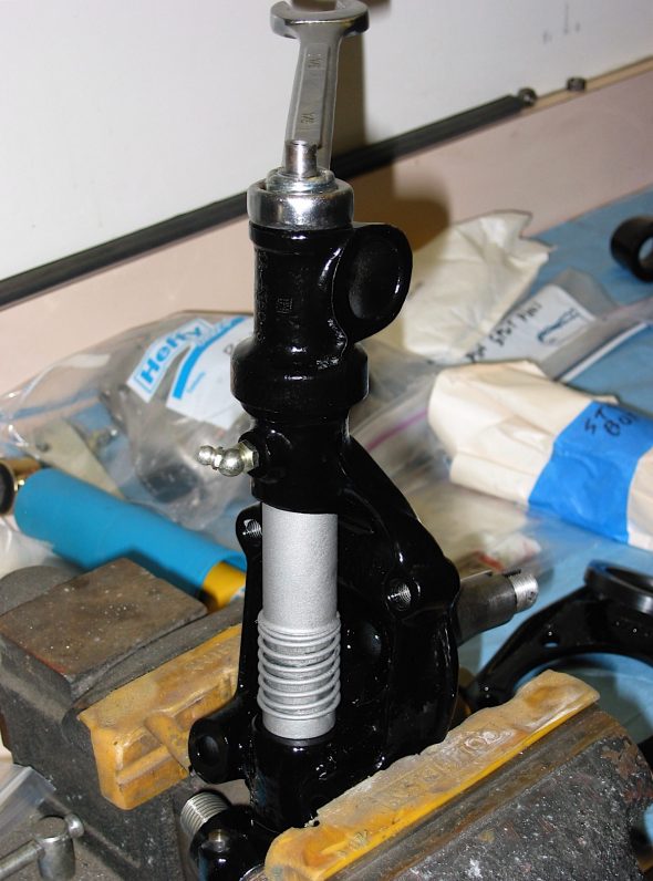
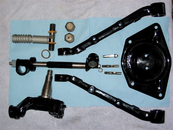
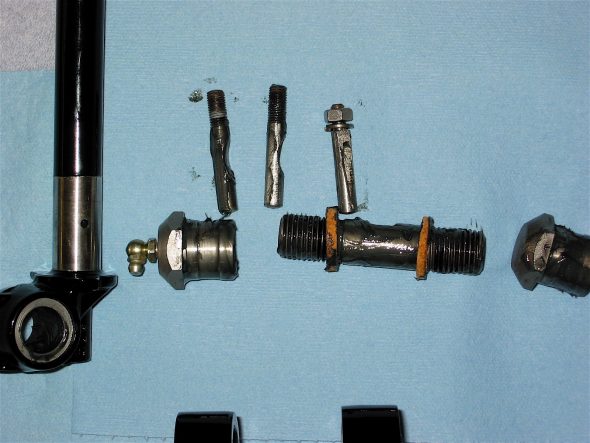
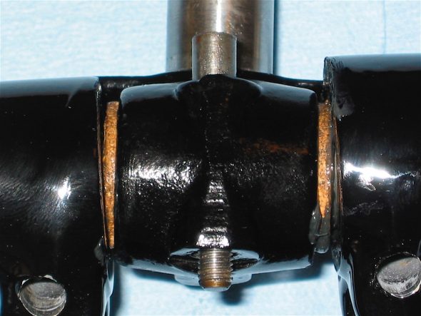
The New Year itself began with attention turning to the front suspension of the Bloody Beast. The first step was the assembly of the swivel axles. Bruce Phillips at Healey Surgeons rebushed and reamed the axles for me and supplied new swivel or “king” pins.  I then applied a light coating of moly to the pin itself and slid the cork washer, with the chamfered edge down, onto the pin. The swivel pin can then be inserted into the axle and three thrust washers are applied to the top of the pin. One “oilite washer” is sandwiched between two “staybright” washers. The oilite washer was first soaked overnight in motor oil. The top trunnion was then placed over the top of the swivel pin and tightened down with a nylock nut. .002” is the maximum permissible lift.

Swivel Pin Spring

Swivel Axle

Swivel Pin lower trunnion

Upper Trunnion washers 3

Upper Trunnion tightening


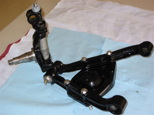
I then collected the components needed to assemble the swivel axles to the frame. These included two paired control arms, the assembled swivel axle, the control arm and upper trunnion bushings, the necessary cotter pins, the shock damper, the lower trunnion bushings, cork seals and the lower link fulcrum pin.

Front Suspension Assembly 2

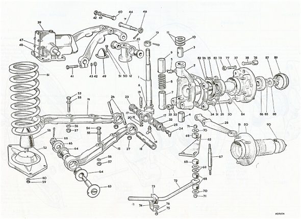
The factory workshop manual provides a very helpful illustration of the components and their relationship to each other.

Front Suspension Schematic


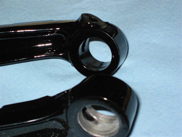
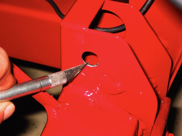
I had paint inside the journals of the control arms and the shock dampers, as well as the holes for the cotter pins so it was first necessary to clean these areas so the paint would not restrict access.

Control Arm Paint

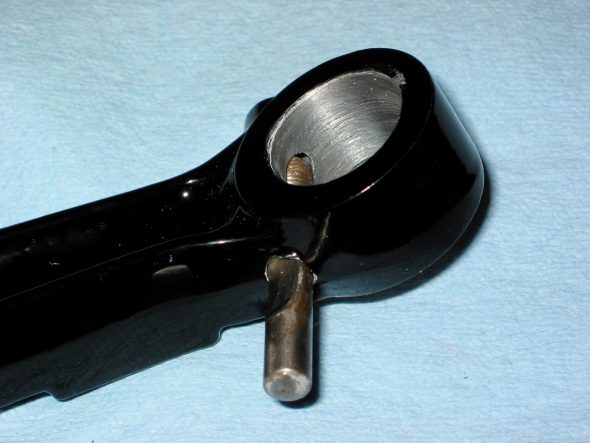
To assemble, I had the side of the control arms with the flats for the cotter pin nuts facing down. I then fastened the spring plate to the control arms so that the alignment of the assembly would be correct. The grease fittings on the lower trunnion bushes face the front of the car. The cotter nuts should be tight but not so tight as to risk distortion of the bushes. The bushes are tightened to the control arms and then backed off a flat. A .002 feeler should be able to be inserted between the face of the bushing and the control arm.

Control Arm Cotter Pins

Lower trunnion components

Lower trunnion in place 2

Front Suspension Asembly 1


Then the time came to secure the swivel axle assembly to the car. Again, the first step was to remove paint from the frame openings that received the pins.

Cleaning hole for pin

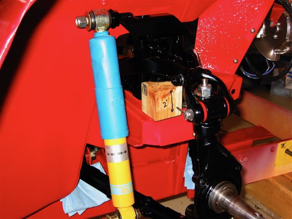
Next the small shock rubber bumpers were screwed onto the shock mounting plate. The shock damper sans its valve was fastened to the frame, and Udo Putzke’s tube shock conversion upper bracket was also bolted in.

Front shock 7


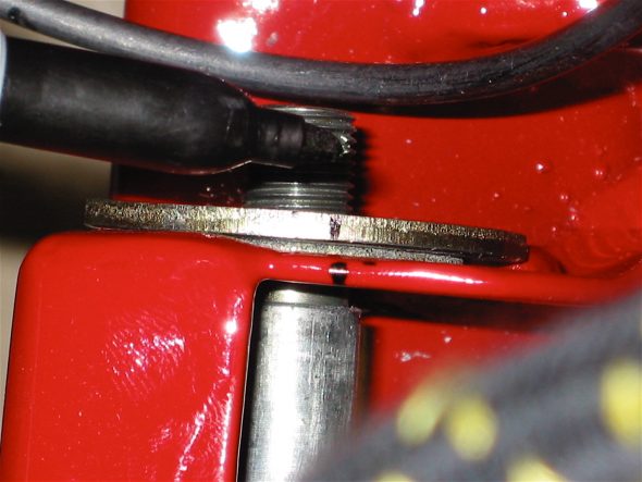
Getting the face plates of the lower fulcrum pin washers to line up can be a challenge, so before final assembly, I pressed them against the frame fitting and marked a line on the face plate and the frame to make alignment much easier later.

Marking pin placement

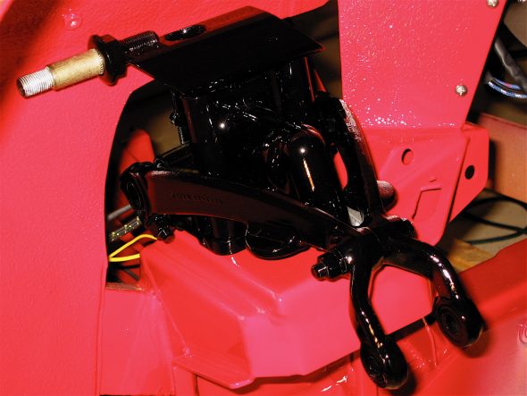
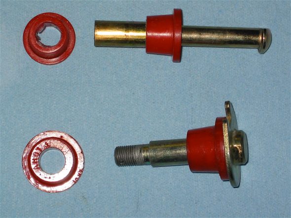
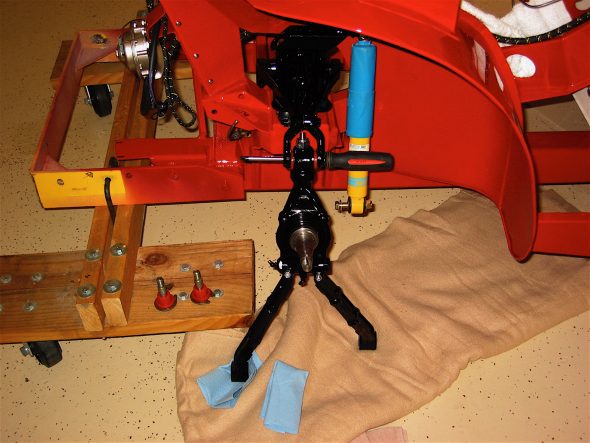
The poly bushings were then placed on the pins and the control arms were lifted up to the frame. A screwdriver was used in the upper link to support the weight of the assembly while it was positioned to secure.

Front poly bushings


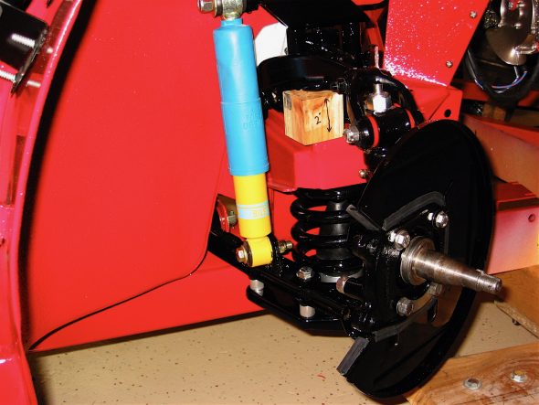
As per the workshop manual, a two inch block of wood was inserted under the lever shock to lift it to the proper ride height and then the shock and the lower fulcrum pins were tightened. A split pin was inserted into the hole through each fulcrum pin and bent back.

Temporary pin for shock

suspension spacer

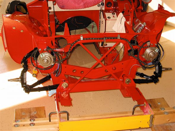
Installed axle assemblies


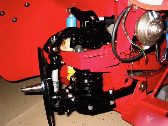
The next task was to install the spring plate and springs, the lowering spacers and bolts, the bilstein shocks, the disc brake dust shield and the caliper mounting bracket. These steps were complete for the left and right hand side of the car.

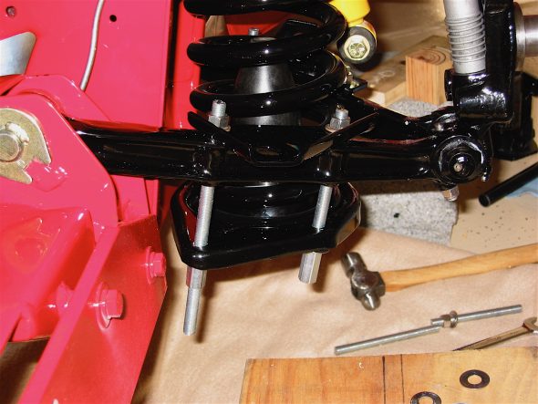
I used four pieces of 3/8” fine thread rod to help install the springs. The two rear rods were cut to about 7” lengths and the two front rods were about 5.” I also used long extension couplers and a flat washer on the rods below the spring plates to make it easy to access the nut with the wrench. A single regular nut would “hide” under the plate and be hard to get to. This arrangement worked well.

Installing coil springs

The spacers from Denis Welch were inserted between the spring plate and the control arm and the lower nuts were screwed up tight with the spring in place. Then one at a time the nut was taken off the top of the rod, the rod was tapped out of the hole through the control arm and spring plate and the longer than normal fastening bolt from the Welch lowering kit was installed.

Lowering Spacers 2


The Bilstein tube shock was then put in place and tightened with nylock nuts. This required lifting the shock with a bottle jack so that its bottom fixing hole would line up with the bracket on the control arm. 

The rubber seals were then glued to the dust shield. I discovered that they probably did not need to be glued as they are a tight fit once the dust shield and the brake bracket come together. The steering arm, brake bracket and dust shield were then bolted to the swivel axle. A tab washer is used on the lower two bolts. The wood spacer block will remain in place until the wheels/tires are installed and the car is lowered to the ground.

Dust shield installed

Chapter 35 Restoration Assembly, Week Two 12/24/2006

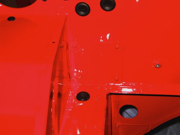
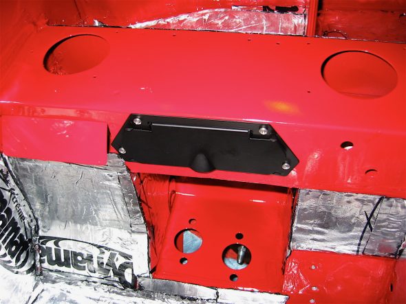
Because of family schedules we celebrated Christmas (gift giving) on Christmas Eve this year, so Monday, Christmas afternoon was devoted to garage work on the Healey. I continued with the installation of the Dynamat Extreme and finished the right side pedal assembly box. I will wait until a little later to finish the dynamat in the interior. The blanking plates were next: one plate with screw clip nuts for the right side master cylinders, 2 plates to cover the steering shaft holes for RHD (one in engine compartment and one in the interior), and finally two plates with the hole for the steering shaft grommet on the left side of the car for LHD cars (again one in the engine compartment and one in the interior). I painted all the flat washers and screw heads for the plate installations.

Blanking Plate 1

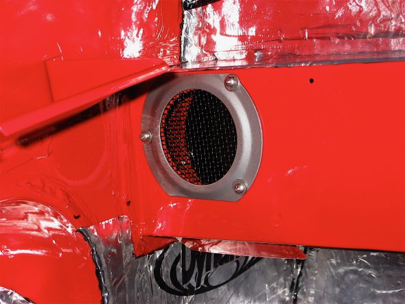
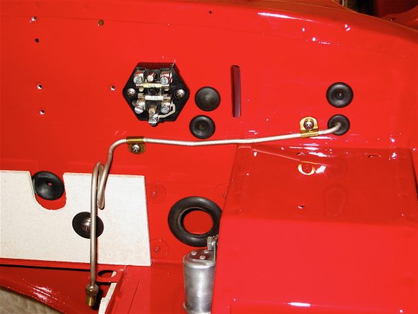
I then fastened each of the hot air outlet interior door assemblies and thebulkhead flange bezel. Followed by the fuse block, the double clip for the clutch and brake lines from the masters to the fluid reservoir, the flasher canister and the new flasher relay.

Bulkhead Flange Bezel


Vent Doors

Fuse Block and Oil Gauge Line

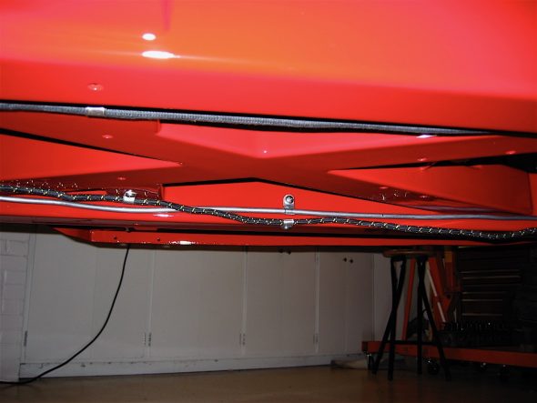
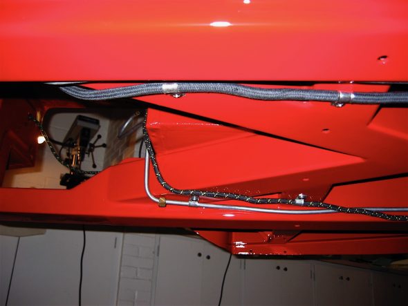
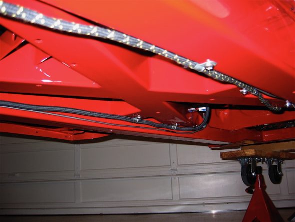
Well, it is a new day and I am ready for some new challenges. I will get started on the battery cable from British Car Specialists and the wiring harness from British Wiring, Inc. I pushed the harness through the firewall grommet from the interior and separated the strands. I decided to focus on the under car runs first, so after jacking up the car on stands I installed the harness wire that goes to the boot for the fuel pump, fuel sender and rear lights. I skipped the clip attachment to the bump box until I have the rear axle in place.

Wiring Harness 4

Wiring Harness 5

Next I shifted my attention to the battery cable. I got it in place and quit for the day. Tomorrow will be dedicated to connecting the harness under the bonnet and in the boot.

Battery Cable 1

Battery Cable to Starter Solenoid

Harness left side

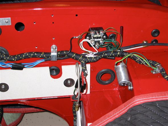
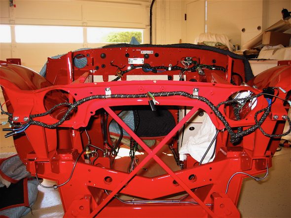
Wednesday was a good day. I started with the harness on the left side of the car. I secured the harness in the engine compartment with the appropriate zinc fastening clips and connected the wires to the fuse block, the flasher canister, connected and then threaded the dip switch mini-harness through the firewall, connected and threaded the mini-harness for the wiper motor through the firewall, connected the eight wires to the flasher relay box, and connected the front lamp pigtails and routed the harness through the front of the car.

Fuse Block & flasher

Flasher relay

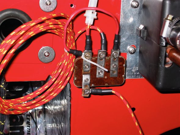
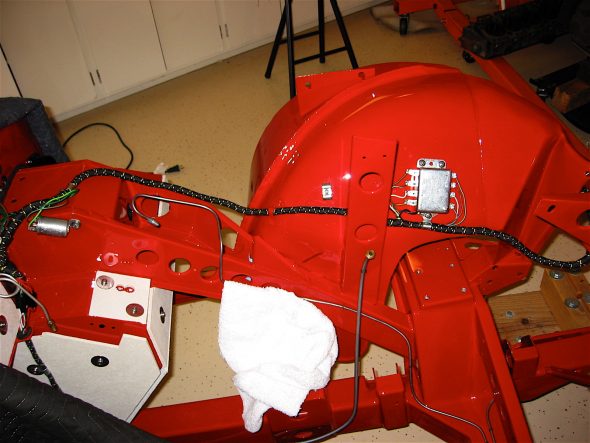
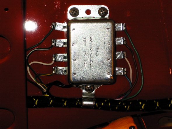
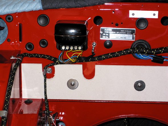
Then I shifted to the right side of the wiring harness. I modified the voltage regulator box to accommodate wiring for an alternator. This is done by cutting out the connectors in the back of the box and then connecting the three brown wires to the same post, and the two yellow wires together to another post.

Harness front view

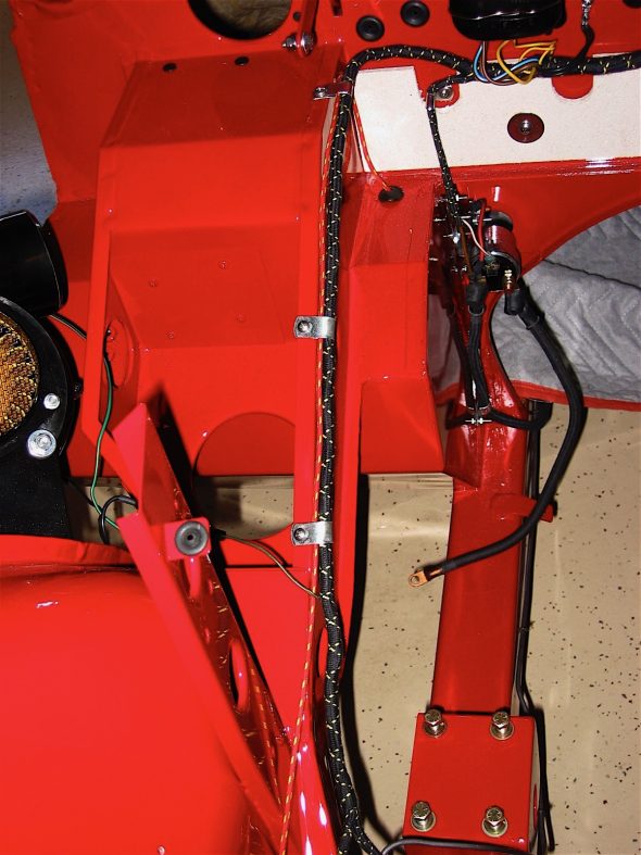
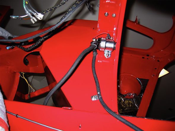
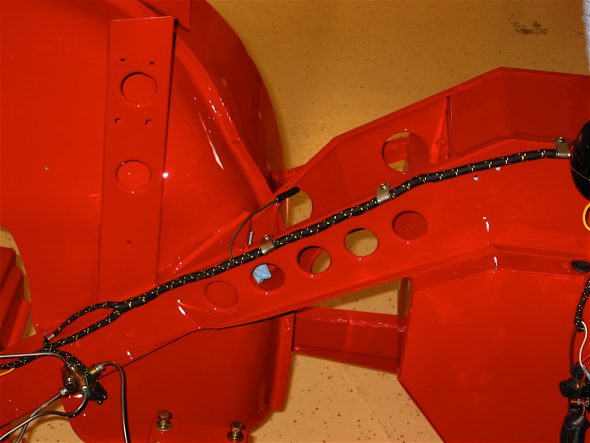
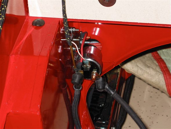
I then connected the harness to the starter solenoid, and routed the wire down the right side support. Feeders to the ignition, alternator, brake switch, and heater blower route off of the primary harness.

Voltage Box

Harness Right Side

Solenoid Wiring_2

I finished the afternoon installing the battery master switch in the boot. I heard complaints from too many about the original switch so I changed to a modern variant and modified it to fit in the original housing.

Battery Master Switch

Boot Battery Cables

Boot Wiring

I then connected the ground strap, added a few rubber grommets, and routed the wiring to the back of the carwhere a rear lighting harness was connected and fastened with two zinc clips. All-in-all it was a productive day!

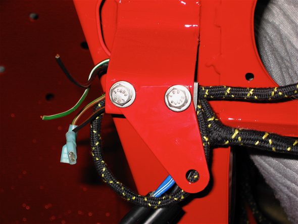
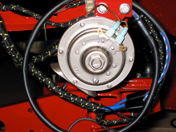
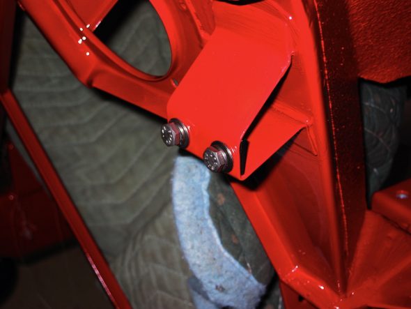
Back to the garage the next day, I installed my modified horn brackets and the horns. These are not the proper horns, but at least I got them painted the right color. I used Duplicolor E8800957 “Seattle Silver,” a Honda color, I believe.

horn brackets red LH

horn brackets red RH

Horn painted

They used metric 7mm bolts. Then I installed the little bracket for the bonnet release, the remote control rod support bracket as well as the hydraulic fluid reservoir bracket.

bonnet release rod bracket

fluid reservoir bracket

The bonnet hinges were the next items to install. I greased the clevis pins and used stainless split pins.

Bonnet Hinge

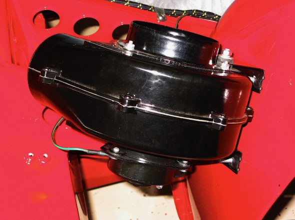
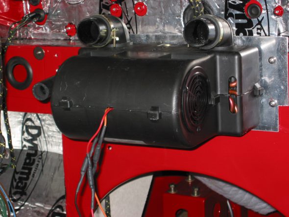
Two big items in my storage bins were the Smiths heater blower and the Cape International interior heater I will be using to upgrade the heating system in the car. The Cape unit, in addition to improved heating efficiency also has a two speed fan. More details are available in the Heating/Cooling section of the website. I went ahead and installed these two items just to make a dent in my storage container!

heater blower 1

Cape heater 2

One thing I wanted to get done early in assembly before tiny spaces got crowded was the installation of the wiper motor assembly rubber grommets. These are a pain to get in, but a little liquid dish soap and muscle did the trick.

Wiper Motor grommets

Chapter 34 Week One 12/18/2016

Even with all the restoration books I have read, and with all the e-mail exchanges, no one prepared me for the fact that I would develop a phobia about touching the car now that it has finally arrived! I am afraid to touch the thing for fear of scratching it!

My plan is to begin with the brake and fuel lines, then move to some of the interior dynamat installation followed by the electrical wiring harness. Along the way I am sure there will be diversions to other bits and pieces. I will try to be disciplined about this process and avoid the temptation to just start attaching pieces to show progress. Although I am confidant that I will succumb to that diversion from time to time!

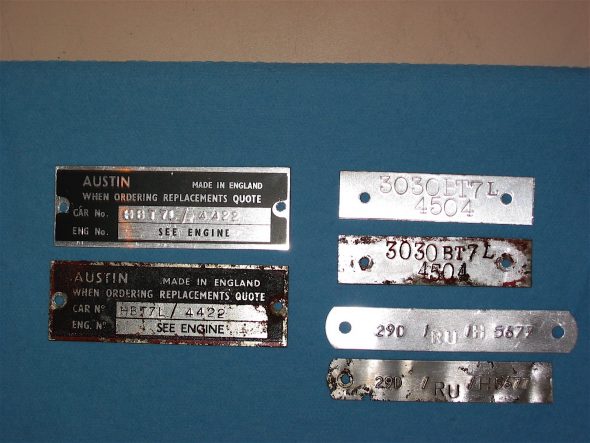
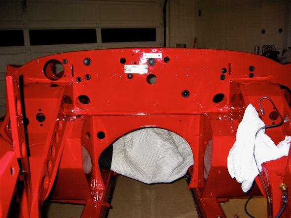
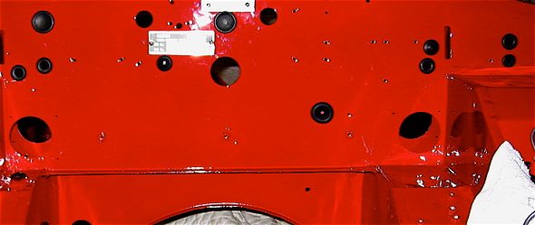
It seemed entirely appropriate that the very first components to be installed should be the two production identification number plates on the firewall. These were produced by Clarke Spares and Restorations. The original ID plates had to be shared with them before they would produce new plates.

Number plates

I.D. Number Plates

Then I began by chasing the threads on all fixed nuts throughout the car to eliminate primer and paint before securing fasteners. Just that little job took about 2 1/2 hours.

chasing threads

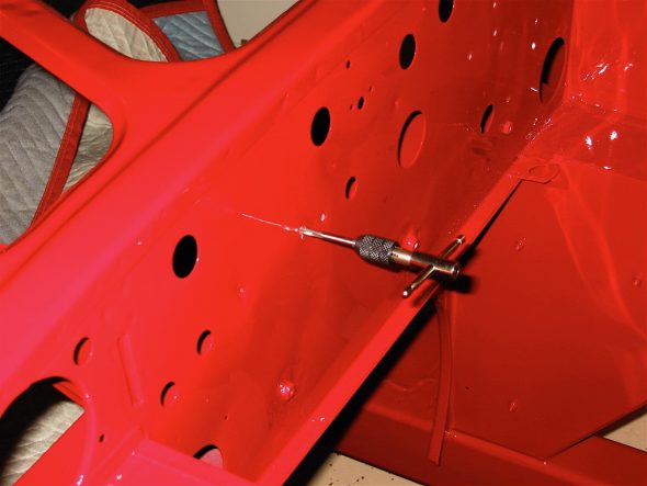
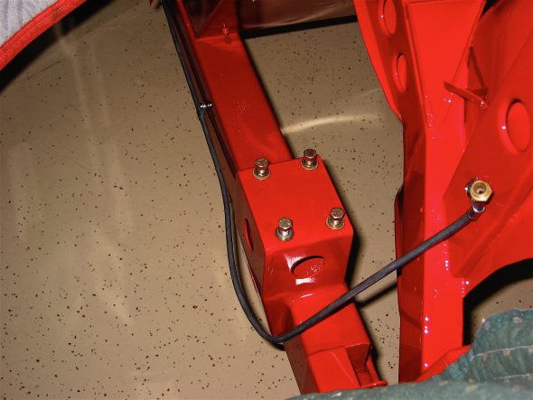
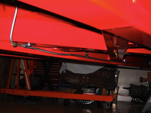
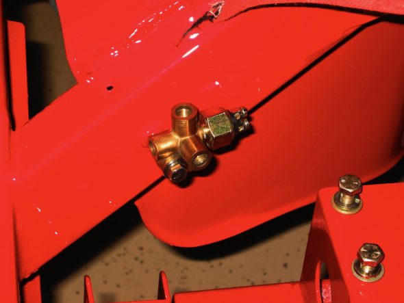
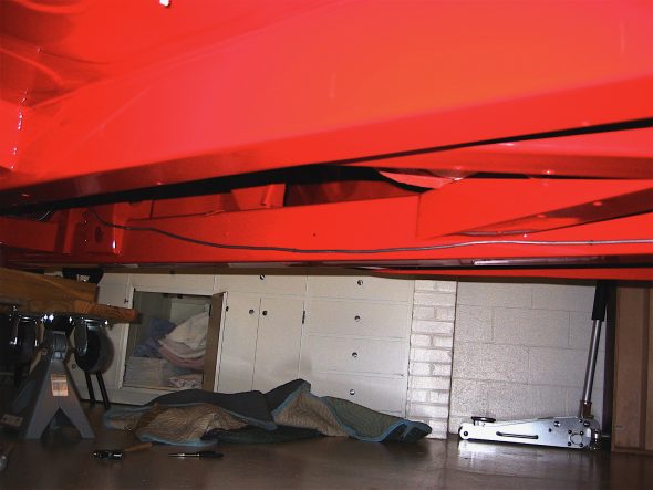
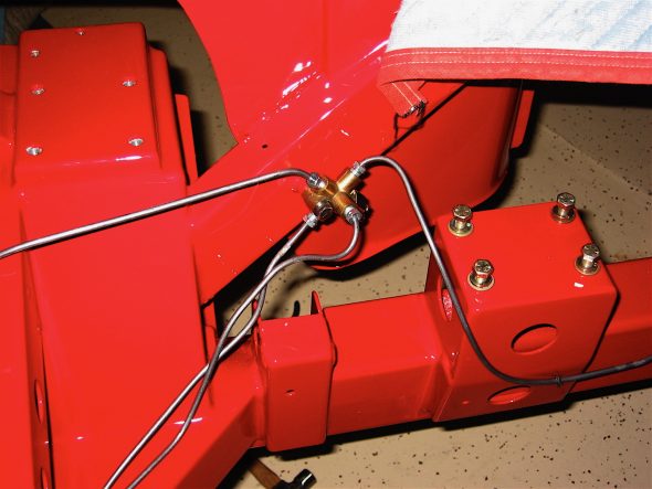
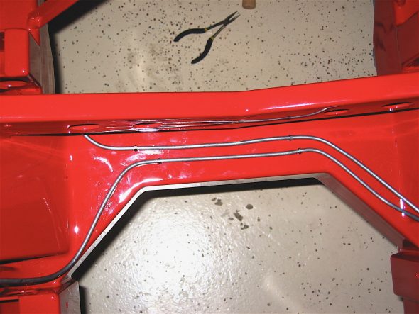
Then it was on to the hydraulic lines. Fuel line first, followed by the brake junction and the brake lines and the line to the clutch master cylinder. Having drilled all the mounting holes after the frame arrived from Martin, this job moved along very quickly.

Fuel line 1

Fuel line 2

brake pipe union

Brake line 2

Brake lines at union

Front brake lines

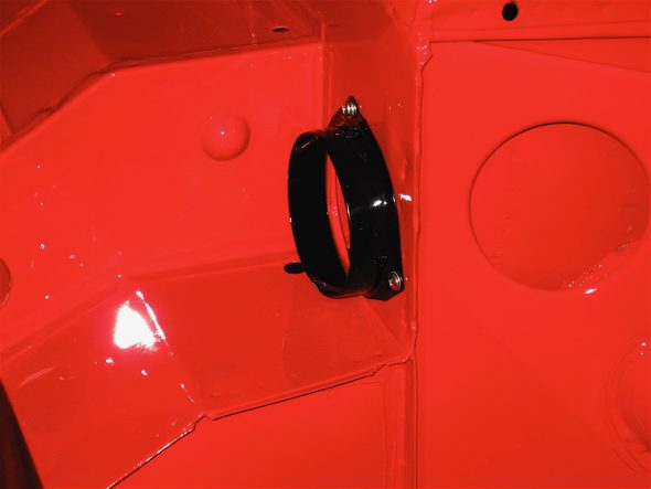
My first two diversions were the horn brackets and the air intake flange. These were installed next. Then came the firewall rubber grommets, and again this job was made easier because I had pre-fit and numbered these at an earlier stage.

air intake flange

Horn bracket

rubber firewall grommets

I moved on to beginning the process of controlling interior cabin heat and improving sound insulation. Fred Wescoe produced an excellent piece on interior insulation that proved very helpful. Making your Healey Cool Fred Wesco .

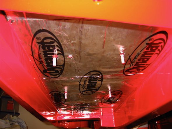
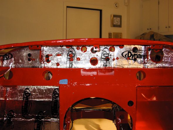
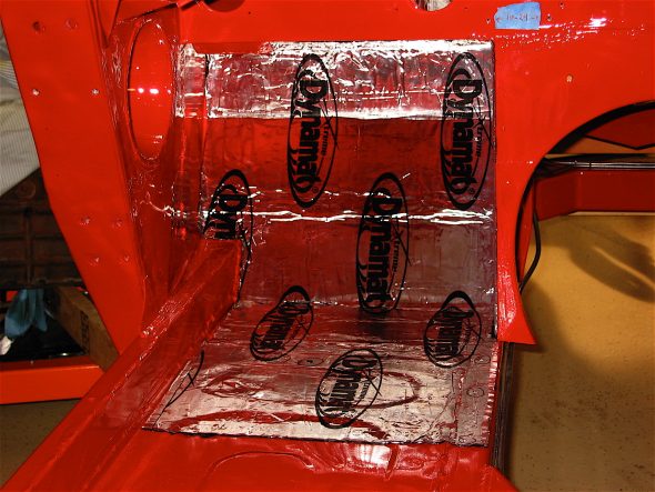
Our cars originally used a tar paper product and jute under the carpet for this purpose, but contemporary products provide much improved insulating qualities. On the advice of others I decided to use a product called Dynamat Exteme that has a very sticky adhesive rubber type surface on the underside and a foil surface on the top. After making patterns from butcher paper the individual pieces were easy enough to cut just using scissors. They were then carefully applied and rolled on with a wallpaper seam roller. Aluminum tape was used to seal all of the seams. All of this produces a nice looking appearance that will hopefully keep the heat down in the cockpit.

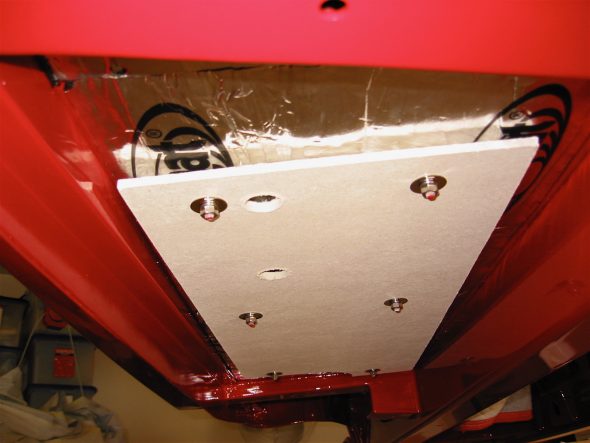
The installation of the first piece of the dynamat extreme went under the car, below the driver’s seat and above the muffler insulation panel. Then the stock insulation panel was secured using the six studs through the floor.

Dynamat Extreme 1

Muffler Insulation Panel

I then moved on to the interior of the firewall and to the driver’s side footwell. I used an awl to find the holes in the interior floor and to make holes through the dynamat material.

Dynamat Extreme 2

Dynamat Extreme 3

Next I fastened the insulation panels in the engine compartment.

Engine Insualtion panels

Chapter 33 – Paint

December 1, 2006

Jeremy’s Painting and Bodywork

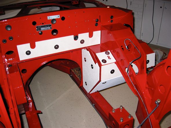
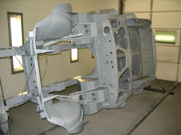
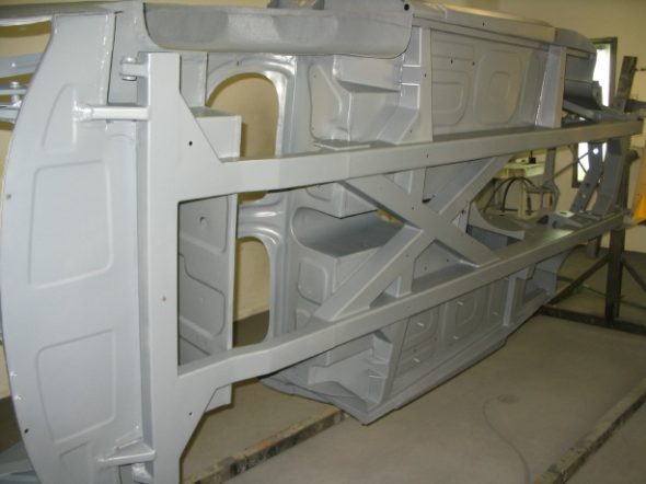
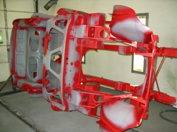
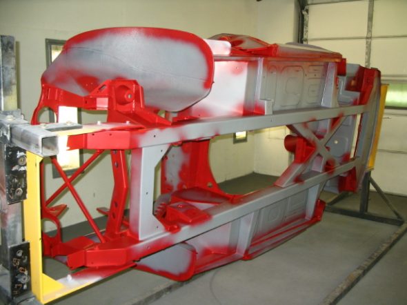
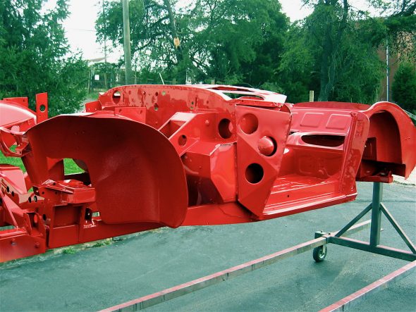
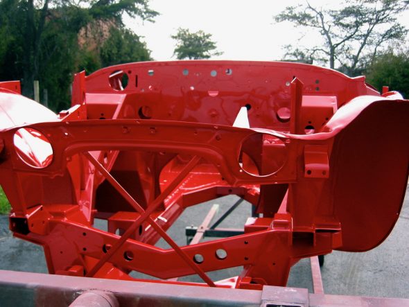
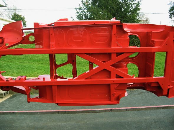
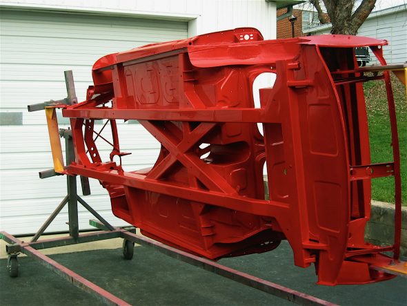
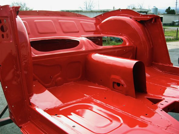
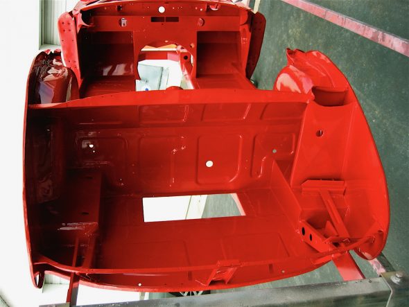
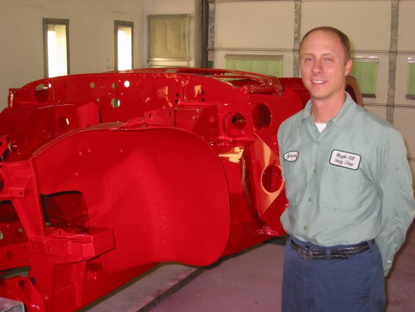
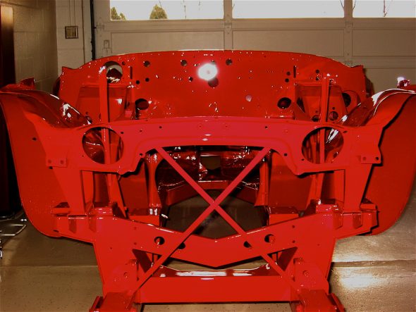
1997 Corso Rossa Ferrari Red Paint – It was a very long day for Jeremy, but in one day three coats of red and two coats of clear coat were applied to the frame and superstructure. As a nervous expectant father, I waited for Jeremy’s call and then went to his shop around 7:00 pm to see the results. I could not have been more pleased. I am really happy with the color of the red. It is going to be beautiful after accent pieces in black and chrome are applied!

Ready for Red 2

Ready for Red 1

First coat 1

first coat 2

red frame 2

red frame 1

red frame 13

red frame 14

red frame 10

red frame 18

Jeremy Turner – Artist!

December 5, 2006

Jeremy’s Painting and Bodywork

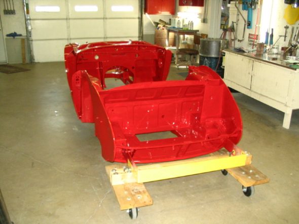
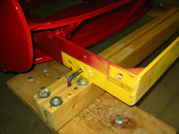
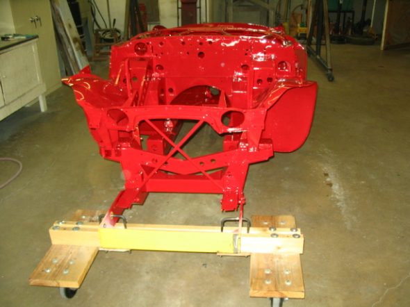
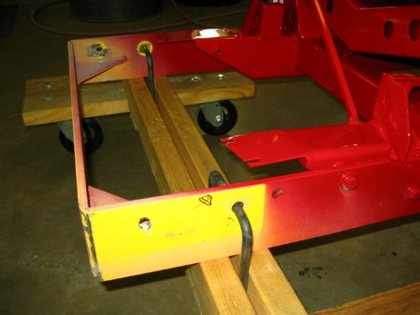
Jeremy got the tub off of the rotisseri and back on the dolly that I had made so that it could be transported back to our home, “Oakview.”

Mounted to move 1

Mounted to move 2

Mounted to move 3

Mounted to move 4

December 7, 2006

Coming Home!!

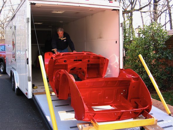
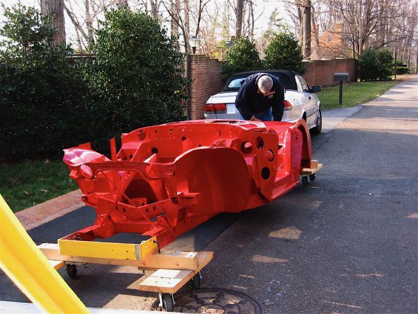
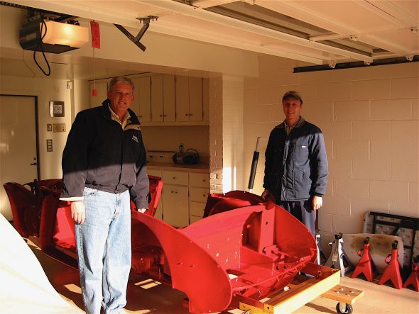
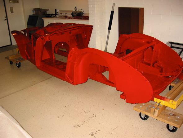
Return to Oakview –   December 7 was the 65th anniversary of Pearl Harbor but it was also the day the “Bloody Beast” came home from Maple Hill Restoration. It was an exciting day. Now the assembly begins, but nobody told me that a phobia would develop. I am afraid to touch the thing for fear of scratching something. It is just so beautiful. I am very pleased with the color.

The new baby is delivered 2

The new baby is delivered 3

The new baby is delivered 7

The new baby is delivered 8

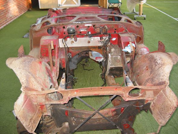
And here is a “before and after” shot. Just a little difference.

Front View Superstructure

The new baby is delivered 

December 15, 2006

Back to Jeremy’s Shop

More Black Bits – There were still some pieces to finish that needed to be painted gloss black. Jeremy finished those up and I will pick them up next week after they have dried.

More black bits 1

More black bits 2

More black bits 5

More black bits 6

The Oil Pump Again – I have been trying to decide about what to concerning the rebuilding or replacement of the oil pump. Jack Brashear reported knowing a good machinist who rebuilds the pumps, so I purchased new gears and will be sending it off to have the pump rebuilt. Too many people reported problems with the quality of the new pumps.

Rear Springs – After completely disassembling, painting, teflon taping, and reassembling the new BT7 leaf springs I had purchased, a conversation with Martin convinced me that I should use some custom made springs that are made by a fellow Martin knows. He claimed that the stiffer Jule frame would “beat the original design springs to death.” Oh well, I have become pragmatic about these things – wasted time, money and effort! I wish I had known about the spring situation earlier. This will slow me down but I want to do it right.

Chapter 32 – Cleaning and Trial Fitting


October 27, 2006

Jeremy’s Rotisseri

More Rotisseri Images –  The rotisseri really does make working on the underside of the frame so much easier. These are a few additional images of the assembly at work.
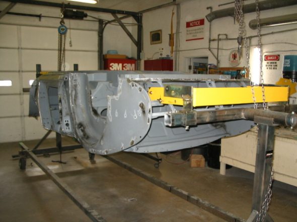
rotisseri 7
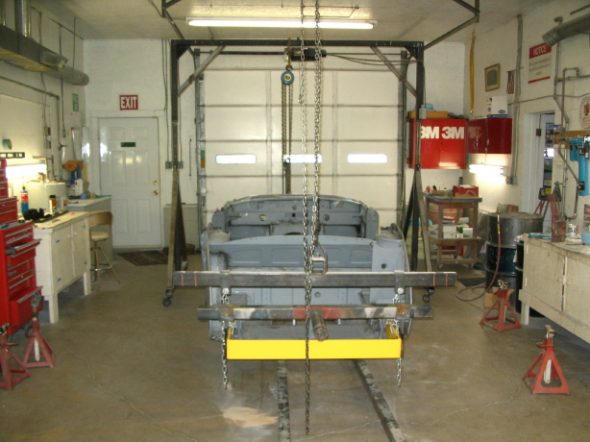
rotisseri 6
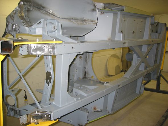
Rotisseri 9
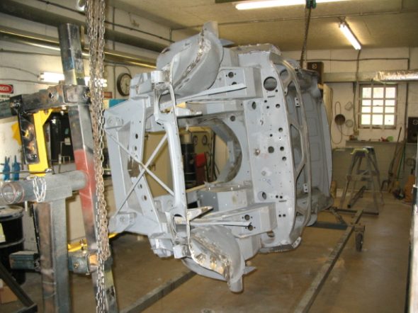
rotisseri 1
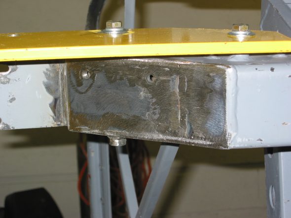
anti-sway bar bracket


November 7, 2006

Jeremy’s Bodywork

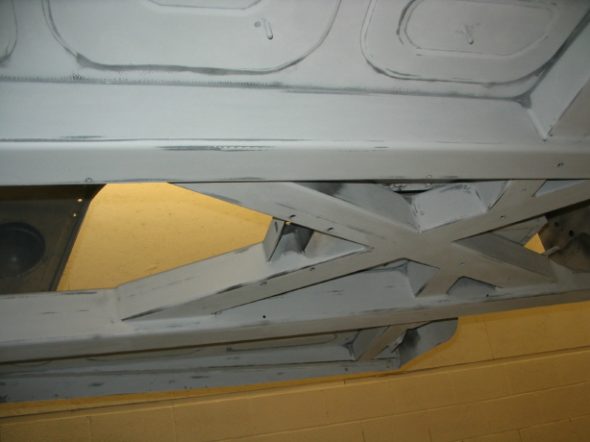
Jeremy has continued to work hard on the final work on the frame/tub. He has done a very nice job with the judicious use of filler to give a nice finished appearance to the frame as if it was the body! Pitting on the outside of the kick panels and on the underbonnet inner fenders just looks great.
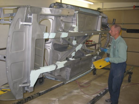
Frame blasted clean 1
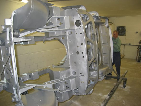
Frame blasted clean 9
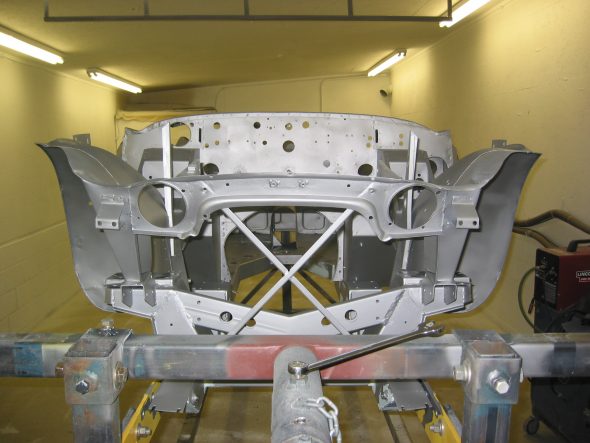
Frame blasted clean 10
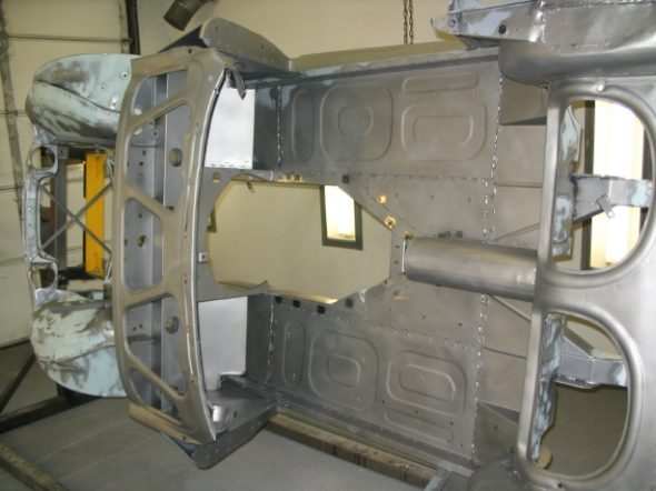
fill primer 3
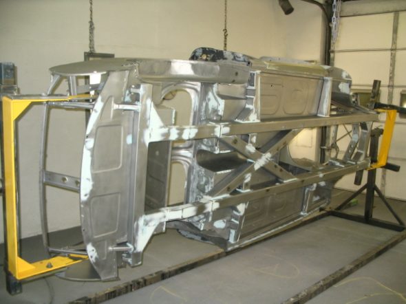
frame bodywork
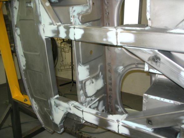
frame bodywork 3
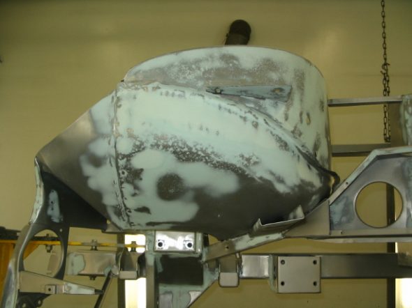
frame bodywork 2
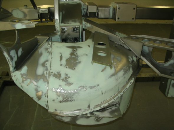
frame bodywork 4
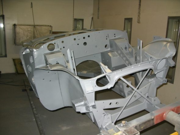
frame epoxy primer 1
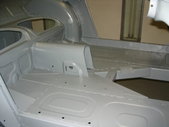
fill primer 4
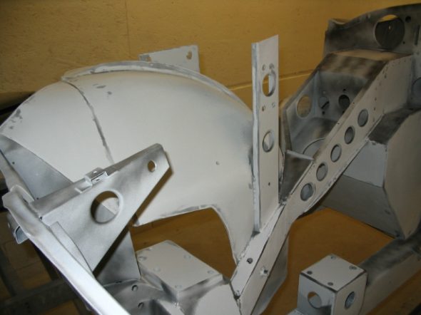
Final sanding 1
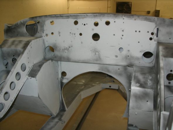
Final sanding 2
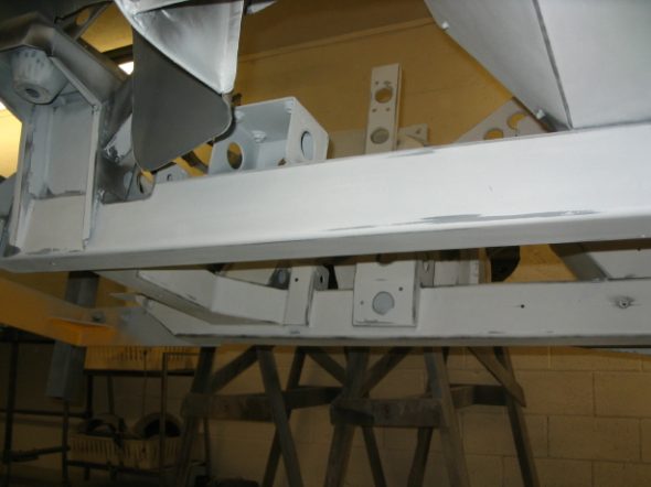
Final sanding 3
Final sanding 4

November 12, 2006

Engine Rebuilding

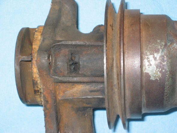
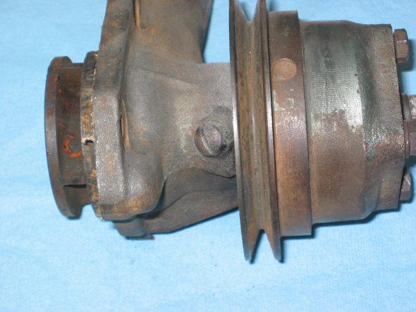
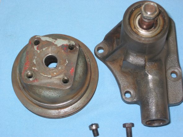
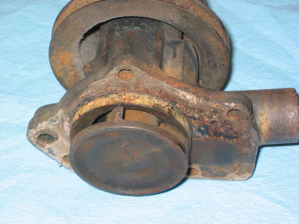
Water Pump – Although Jack Harper will be doing the engine rebuild, there are some items that I can take care of before I take the motor to him. I already sent the rocker arm assembly out for rebuild, and today I queried the internet healey list about their thoughts on the water pump. Was I better to rebuild my own or purchase an after market replacement? Those whose opinions I have come to count on recommended rebuilding my own and perhaps purchasing a new one to have as a spare. Bill Bolton, Peter Caldwell and Joe Curto were suggested as possible rebuilders. I had experience with all three but decided to call Peter since his lever arm Armstrong shock rebuilds will be on my car and because so many rave about the quality of his work.  He indicated that his company didn’t “officially” do water pump rebuilds, but they were getting ready to do a number of them and that I should send mine along His rebuild would be $75.00. I took mine off the motor – four nuts on studs and took the pully off the pump shaft. That required the use of the slide hammer, but was easily accomplished.
Water pump 1
Water pump 6
Water pump 8
Water pump 5

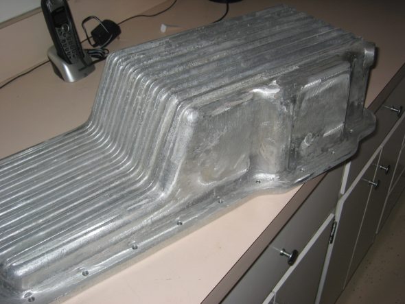
Aluminum Oil Sump – I ordered an aluminum oil sump from British Parts Northwest. After researching the sumps available from various suppliers. Others reported that the BPN sump did not require modification to the oil pump because it is a little deeper than the others. Of course, that also means it protrudes lower in the frame, but since my motor mounts are ¼” high I concluded that it would work best. Unfortunately, it arrived in pretty rouh shape with grinder marks on the exterior and some casting depressions. I sanded the body until most of the grinder marks were eliminated. Jeremy will glass bead blast and we will put a few coats of clear paint on it for protection.
aluminum oil sump 2

November 24, 2006

Jeremy’s Painting and Bodywork

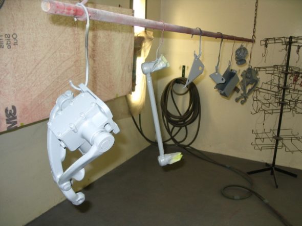
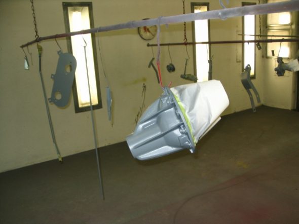
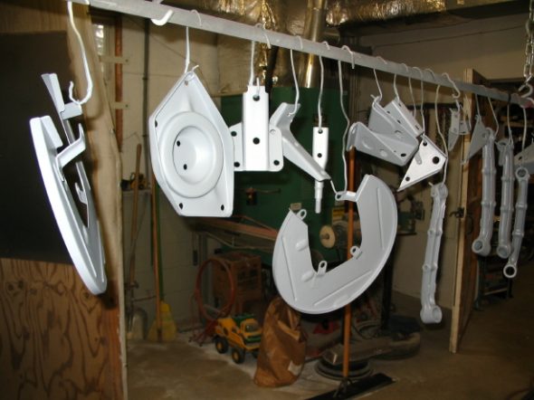
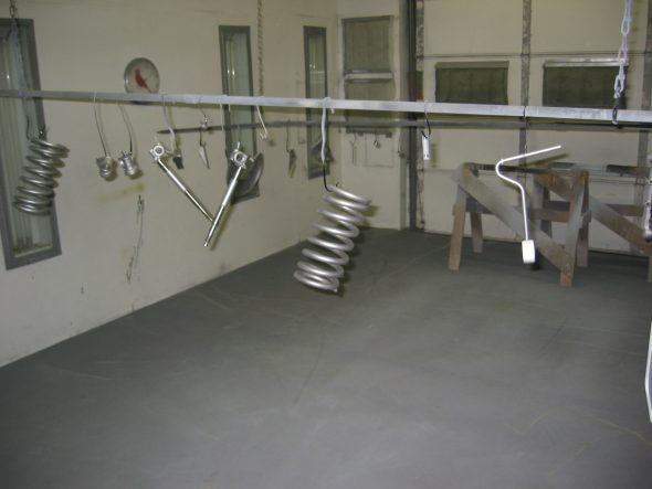
Suspension and other little bits   To take a break from sanding the frame, Jeremy turned again to finishing some of the smaller parts that are to be painted gloss black. The following images show some of the work.
small primed parts 2
media blasted parts 2
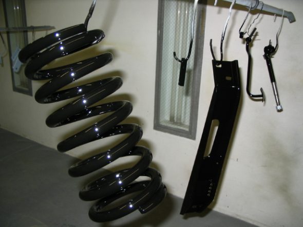
small parts black 1
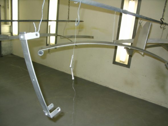
rear springs blasted 1
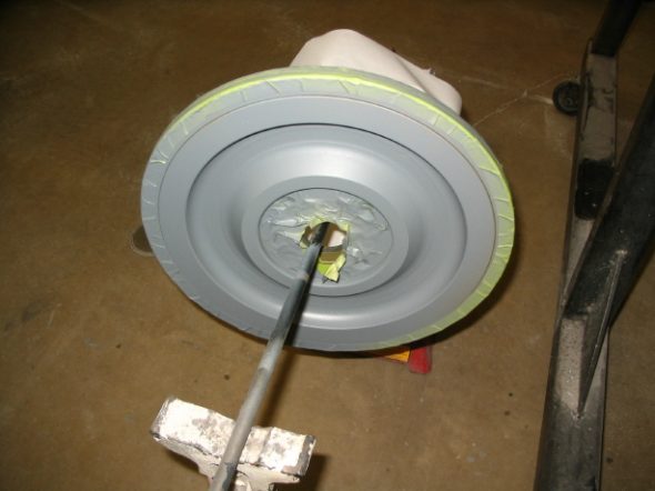
flywheel ready to paint
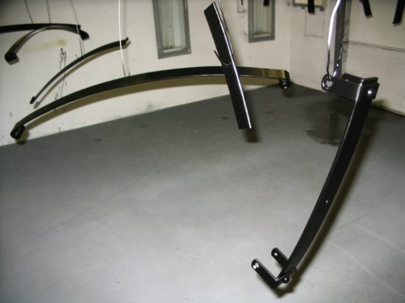
Rear Springs painted 1

Rear Leaf Spring Assembly – The leaf springs were painted semi-gloss. I put a layer of teflon tape between each of the leaves to provide for smoother action between each of the leaves. It should help to eliminate creaks and moans later. The finished products looked very nice.
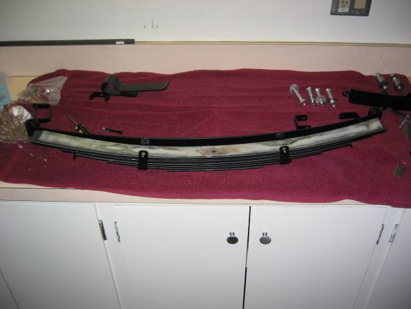
Rear spring glide strips 1
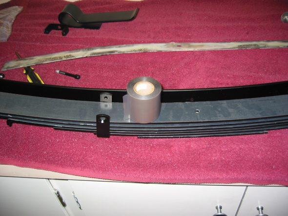
Rear springs teflon tape
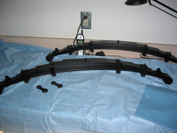
Rear springs completed

Smitty Toyota Transmission Conversion and Clutch Assembly – I wanted to see how the conversion assembly was going to fit so I decided to rmove the gearbox from the bell housing and set things up. The lightened flywheel from Bill Bolton had been cleaned up and painted just for some rust protection. I inserted the aluminum pilot bushing with bearing pressed in by using my lead knock-off hammer and soft drift to keep from damaging the aluminum.
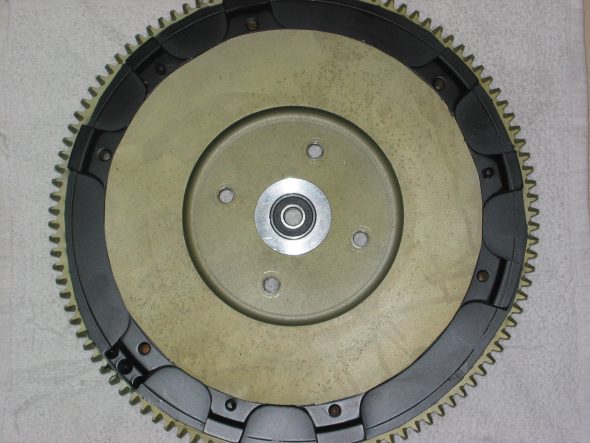
Flywheel Smitty Pilot Bearing

Crank Rear Oil Seal – I will be purchasing an improved crank rear oil seal which will require some modification of the backplate, but for now I just wanted to see how things were going to fit, so I used the backplate as it was. I then fit the flywheel to the crank. Although not in the image below, I will be using the flywheel bolt lockdown tab washers.
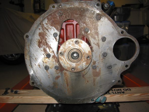
Engine Backplate
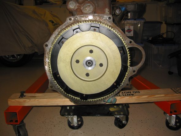
Flywheel installed 1

Then I installed the Pressure plate using the Smitty supplied clutch disk (thicker than stock Toyota) and centered it using the alignment tool supplied in kit. After installing the bell housing it became obvious that the throw out arm did not have sufficient travel without hitting the back edge of the opening in the housing. I will add some length (others have suggested about 3/16” to the pivot fulcrum to gain the travel required.
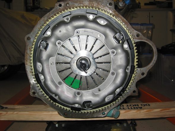
Clutch plate assembly
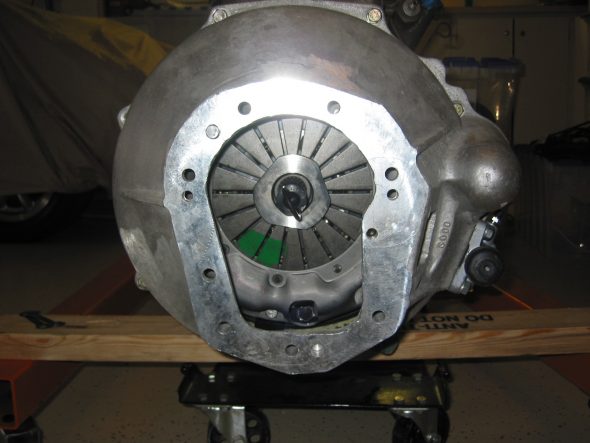
Bell housing installed
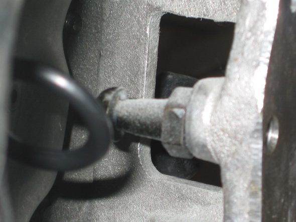
Clutch arm pivot 2
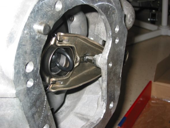
Throw out bearing clutch arm 1
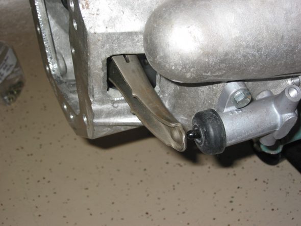
Throw out bearing clutch arm 2
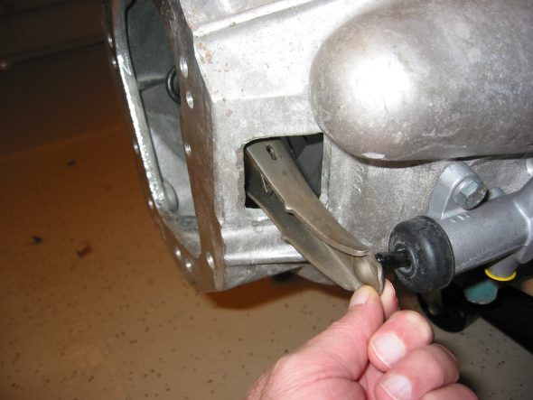
throw out arm 1

November 27, 2006

Back to the Engine Work

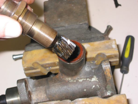
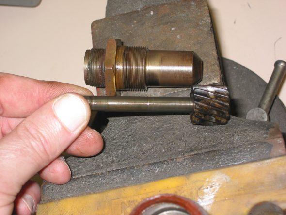
Tach Drive Housing – Detached the tach drive housing from the block. Three ¼” x 7/8” Hex head bolts with flat and lock washers. As per the manual, pulled out the gear drive with a 3” x 5/16” bolt attached to the threaded hole in the drive. Will need to install new rubber seals in the unit.
Tach Drive assembly 1
Tach Drive assembly 2

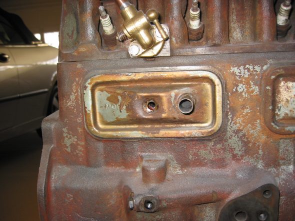
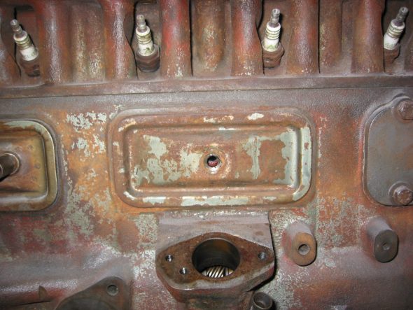
Tappet Cover Plates – There are three covers. The rear cover with the breather pipe is secured with one 1 ¼” x 5/16” hex head bolt with a copper washer and a cork gasket. The center cover is also attached with one 1 ¼” x 5/16” hex head bolt with copper washer and cork gasket. The front cover which is much heavier to support the weight of the generator is secured with five ¾” x 5/16” hex head bolts with copper washers.
Rear Side Cover
Center Side Cover
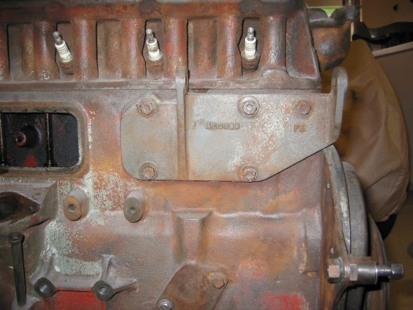
Front Side cover 1

Heater Water Valve –  Secured by two 5/8” x ¼” hex head bolts and washers.
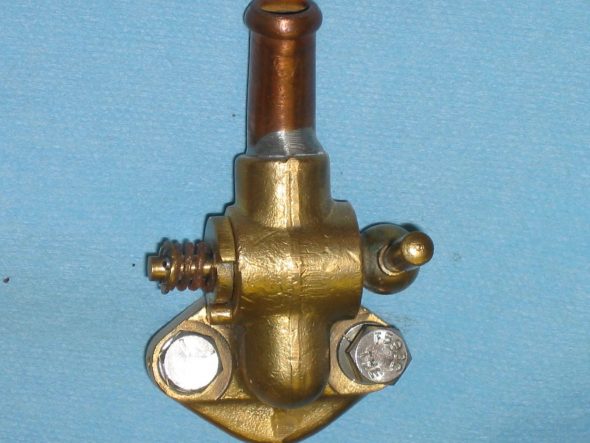
Heater water valve

Blanking Plate – Located on the right side of the motor. Two hex head bolts 5/8” x 5/16.” Course threads with copper washers.
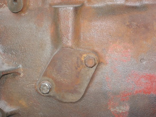
Blanking Plate

Oil Pipe Fitting, back side – One hex head bolt, 3/8” x 5/16” with copper washer.
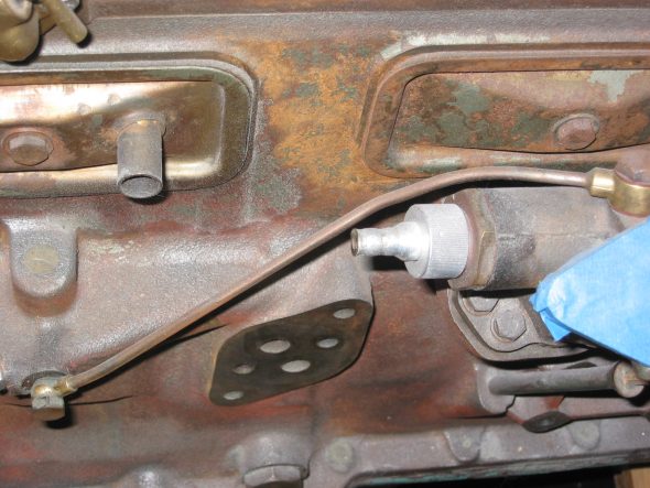
Oil Feed Pipe
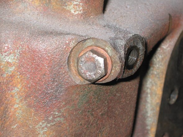
Oil Feed Bolt

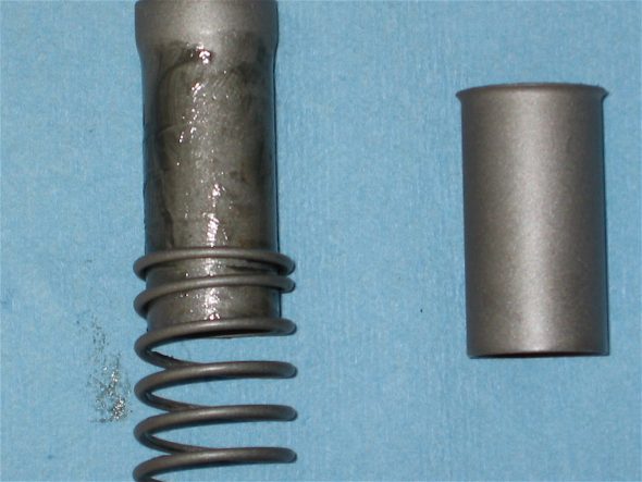
Oil Pressure Relief Valve – One 1 1/8” (wrench size) hex head bolt x 3/8” long. Copper washer with spring and cup.
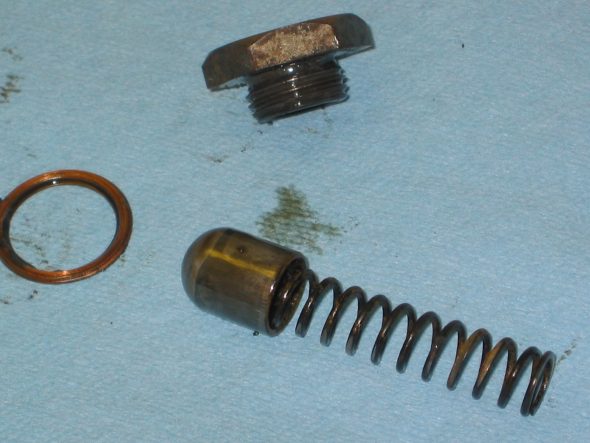
OIl Pressure Relief Valve 2
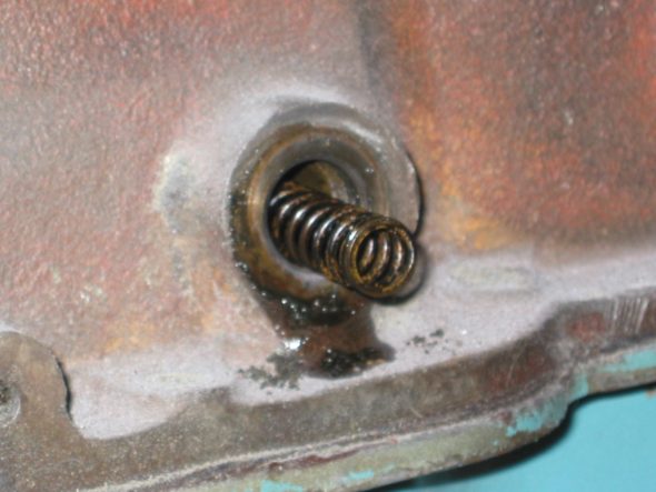
OIl Pressure Relief Valve 1

Plug for Oil Filter Feeder Hole – Right side of block. One 7/8” (wrench size) hex head bolt 3/8” long, with copper washer.
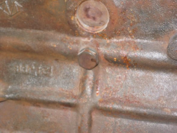
OIl Filter feeder hole plug 1
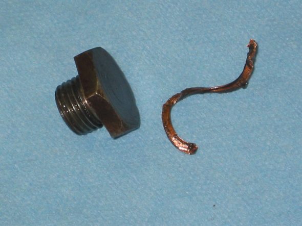
OIl Filter feeder hole plug 2

Union for Oil Gauge Pipe – Right side of block. Nut with pin hole. Fiber washer.
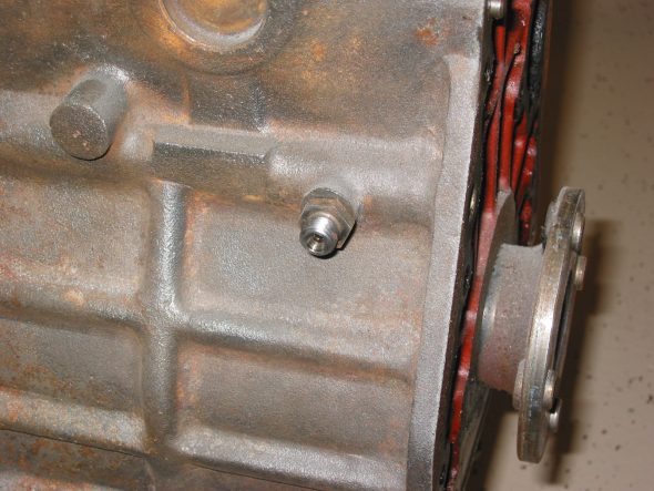
Oil Pressure Pipe Union 1
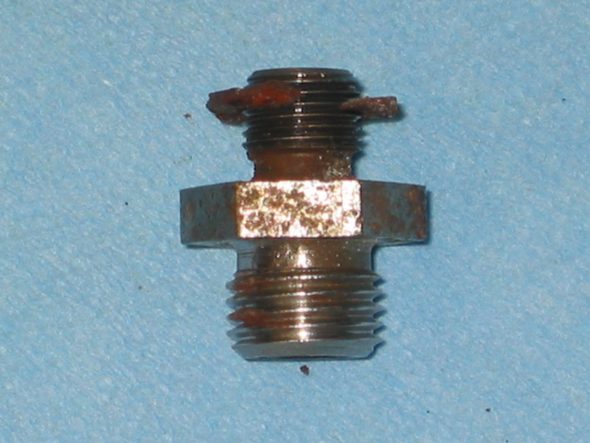
Oil Pressure Pipe Union 2

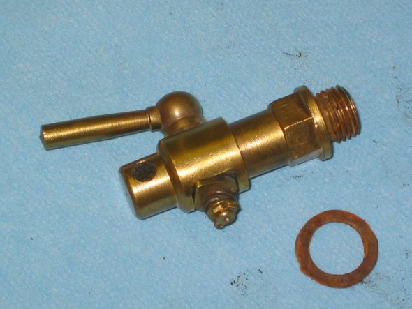
Block Drain Tap – Brass with fibre washer.
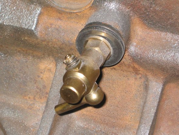
Drain Tap 1
Drain Tap 2

Carb Drain Pipe Brackets – Located at the second and seventh oil sump mounting bolts from the font of the block. ¼” nuts used to secure the clips.
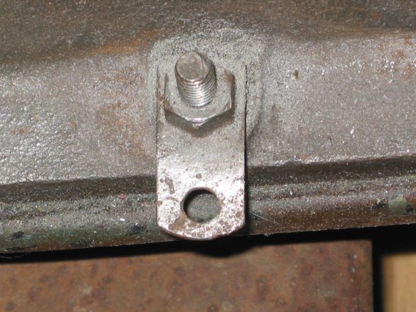
Fuel Drain Pipe Clip 1
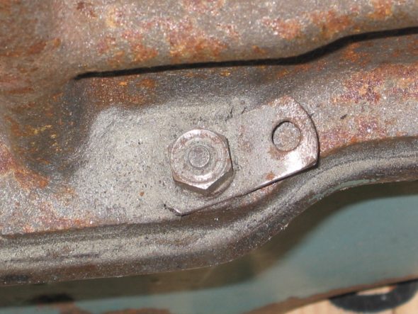
Fuel Drain Pipe Clip 2
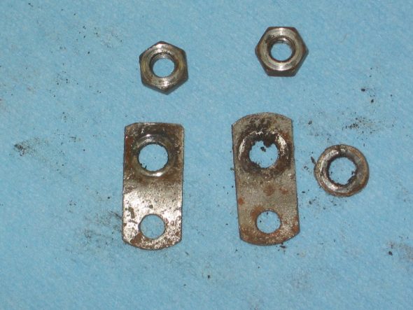
Fuel Drain Pipe Clip 3

November 27, 2006

Jeremy’s Painting and Bodywork

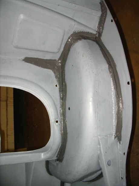
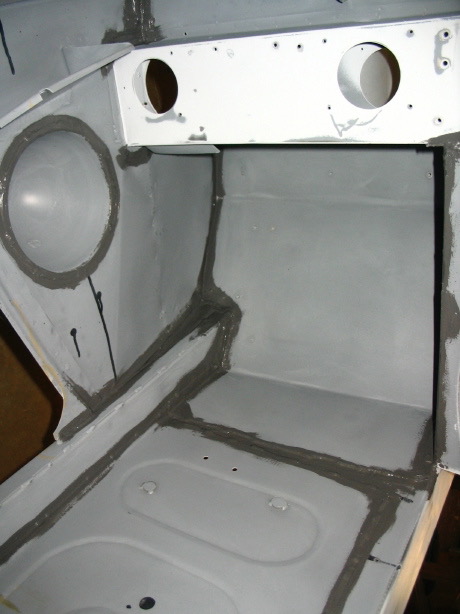
New Seam Sealer and Prep for Chip Protector   Jeremy finished the sanding work and installed seam sealer. 
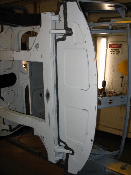
Seam sealer finished 1
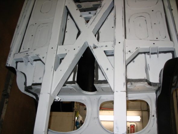
Seam sealer finished 2

Seam sealer 4
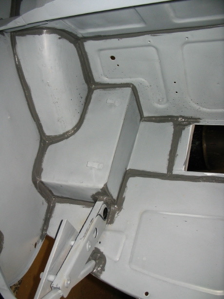
Seam sealer 1
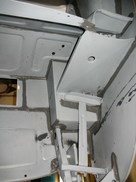
Seam sealer 2
Seam sealer 5
Seam sealer 8

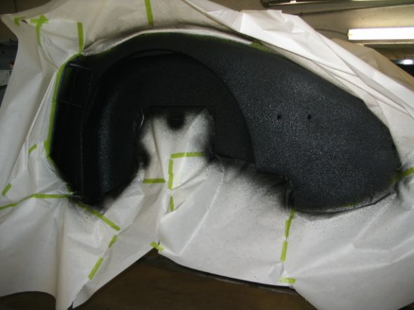
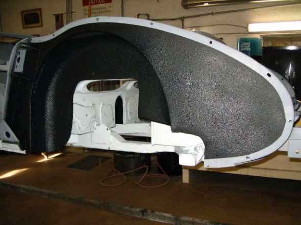
Chip Guard for the Wheels Wells – We decided to use a chip guard product in the wheel wells and will also use the same product under the front portion of the front shroud. It turned out very well, nice even coverage. The final red paint will then be sprayed over the chip guard so that it isn’t quite so obvious. 
Chip Guard 1
Chip Guard 3
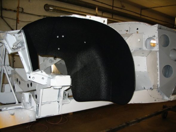
Chip Guard 4

We also drilled access holes in the frame and outriggers and applied an etch primer as well as paint to protect against rust. I will need to decide if I will plug the holes or just leave them open.

Engine Work Again – I received the rebuilt rocker arm assembly from The Rocker Arm Specialists and could not have been more pleased. The installed the new pedestal with the threads for the oil pipe and rebushed the whole mechanism. It looks great as well.
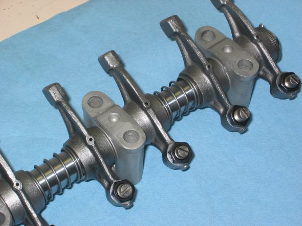
Rebuilt rocker assembly
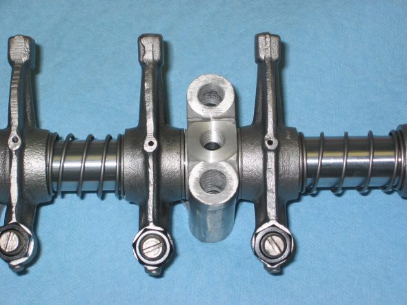
Rebuilt rocker assembly

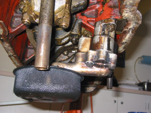
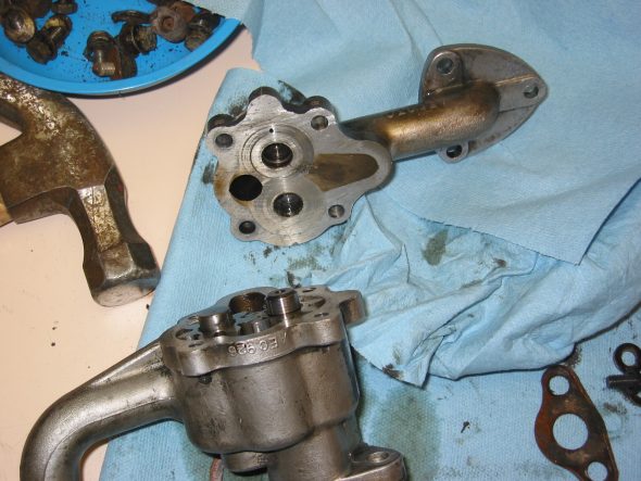
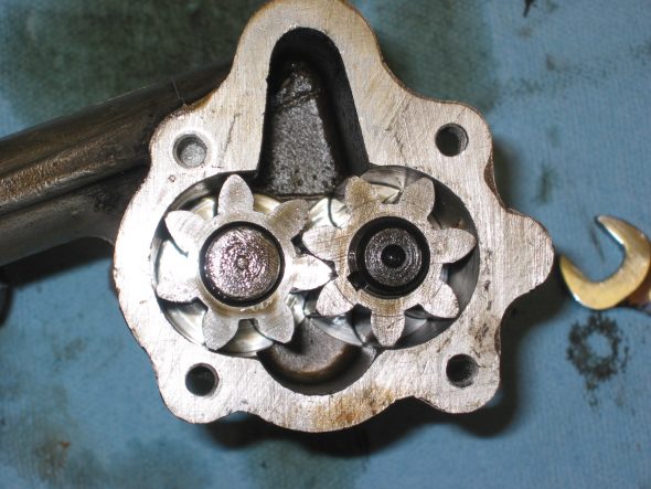
Oil Pump Removal and Inspection – After dropping the oil sump and cleaning it up a bit, I removed the oil pump to inspect it. I think I will go ahead and replace it to be on the safe side. It is the gear type pump, but others have recommended the rotary pump and since the fit is interchangeable, I think I will take their advice.
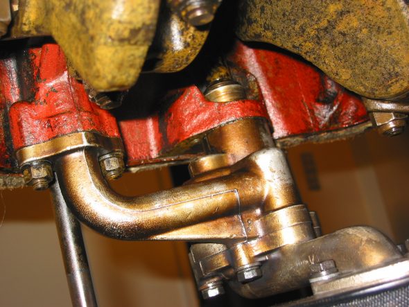
Oil Pump 5
Oil Pump 2
Oil Pump 8
Oil Pump 7