We will be using two types of insulation in the Bugeye. Dynamite Extreme will be applied directly to the metal surfaces in the interior. Then an aluminum duct insulation material sourced from Lowes will be applied on top of the Dynamite. Aluminum tape will be used to seal any seams in the materials.
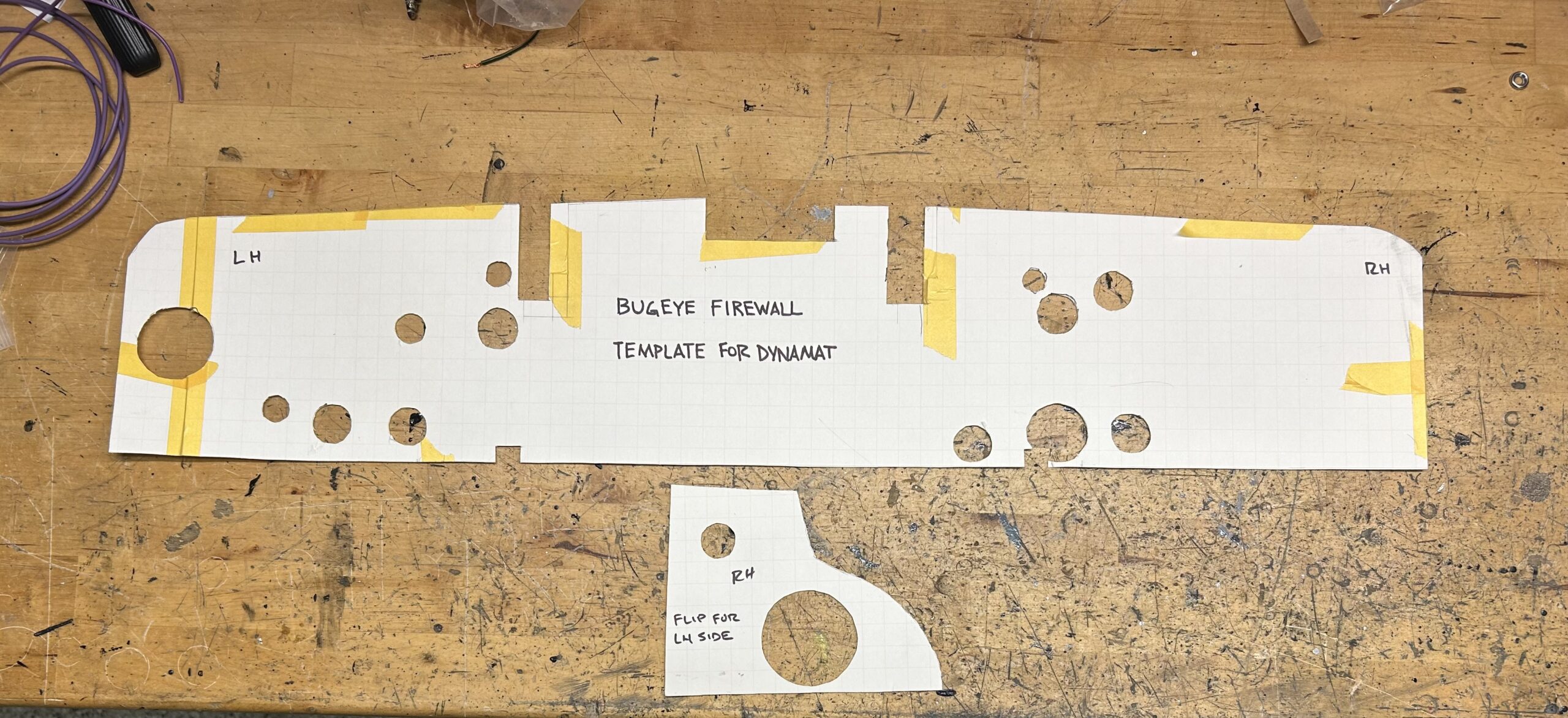
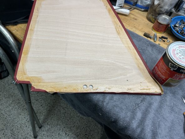
We began this process with the installation of the Dynamite Extreme on the interior of the firewall. This is a little tedious because one first needs to make a template to account for all of the holes in the firewall. The matching holes in the dynamat need to be of a larger diameter than the corresponding firewall holes to account for the rubber grommet that will fit in each hole.
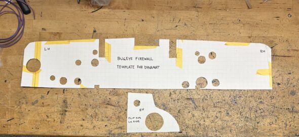
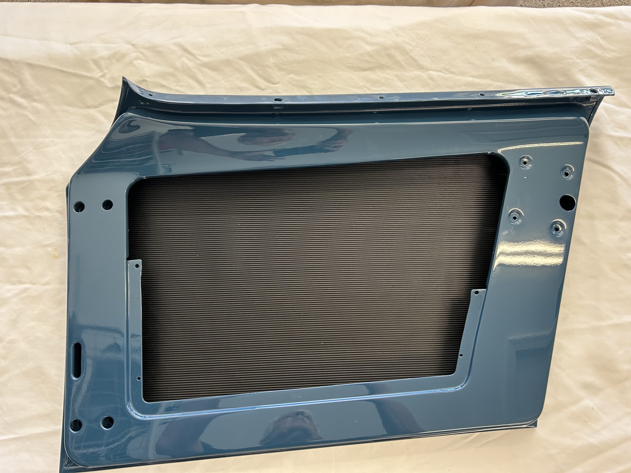
Firewall Dynamite Extreme Template
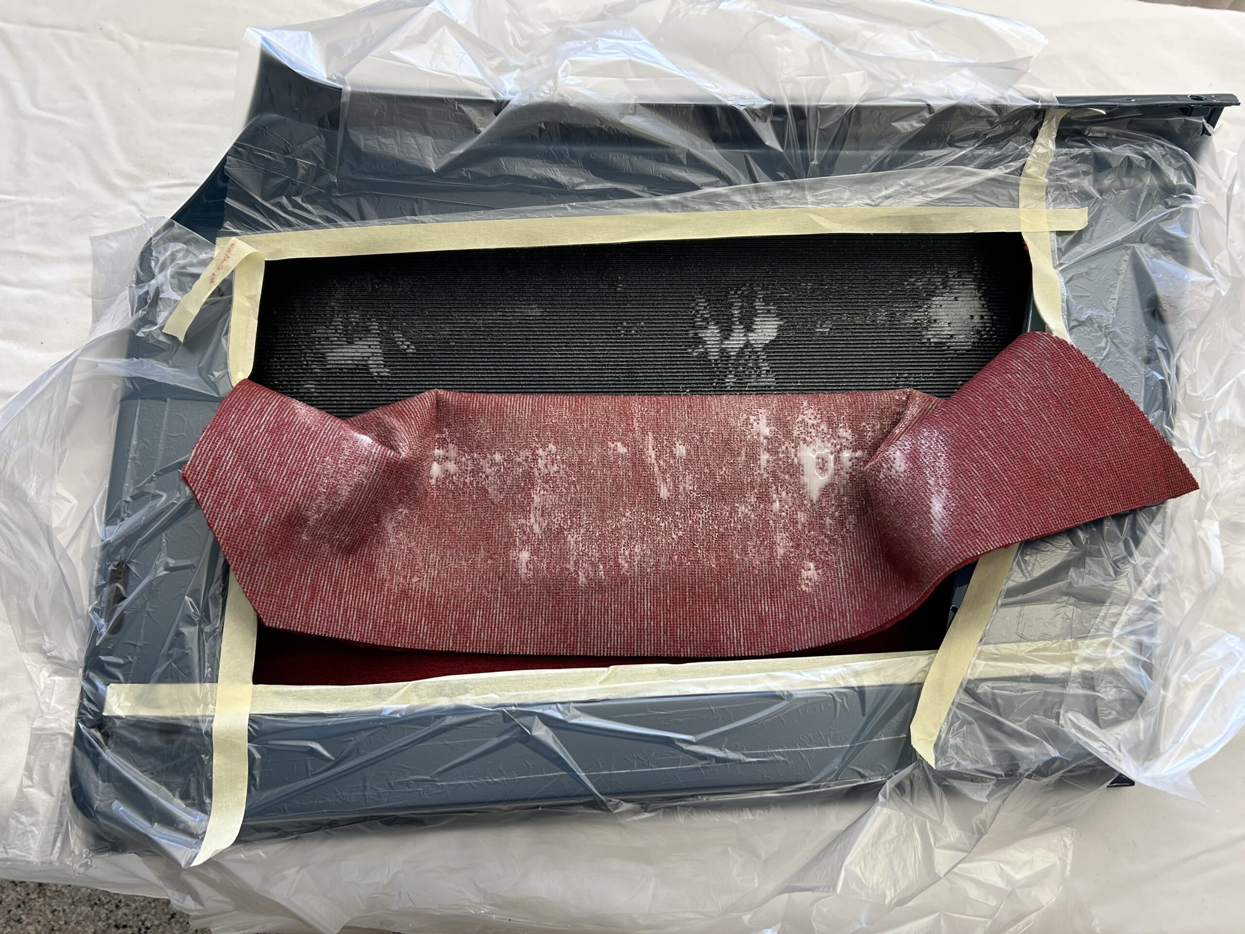
A small applicator wheel was used to press and smooth the Dynamat material against the metal surface. A Gorilla Glue spray contact cement was used to glue the aluminum insulation to the Dynamat.
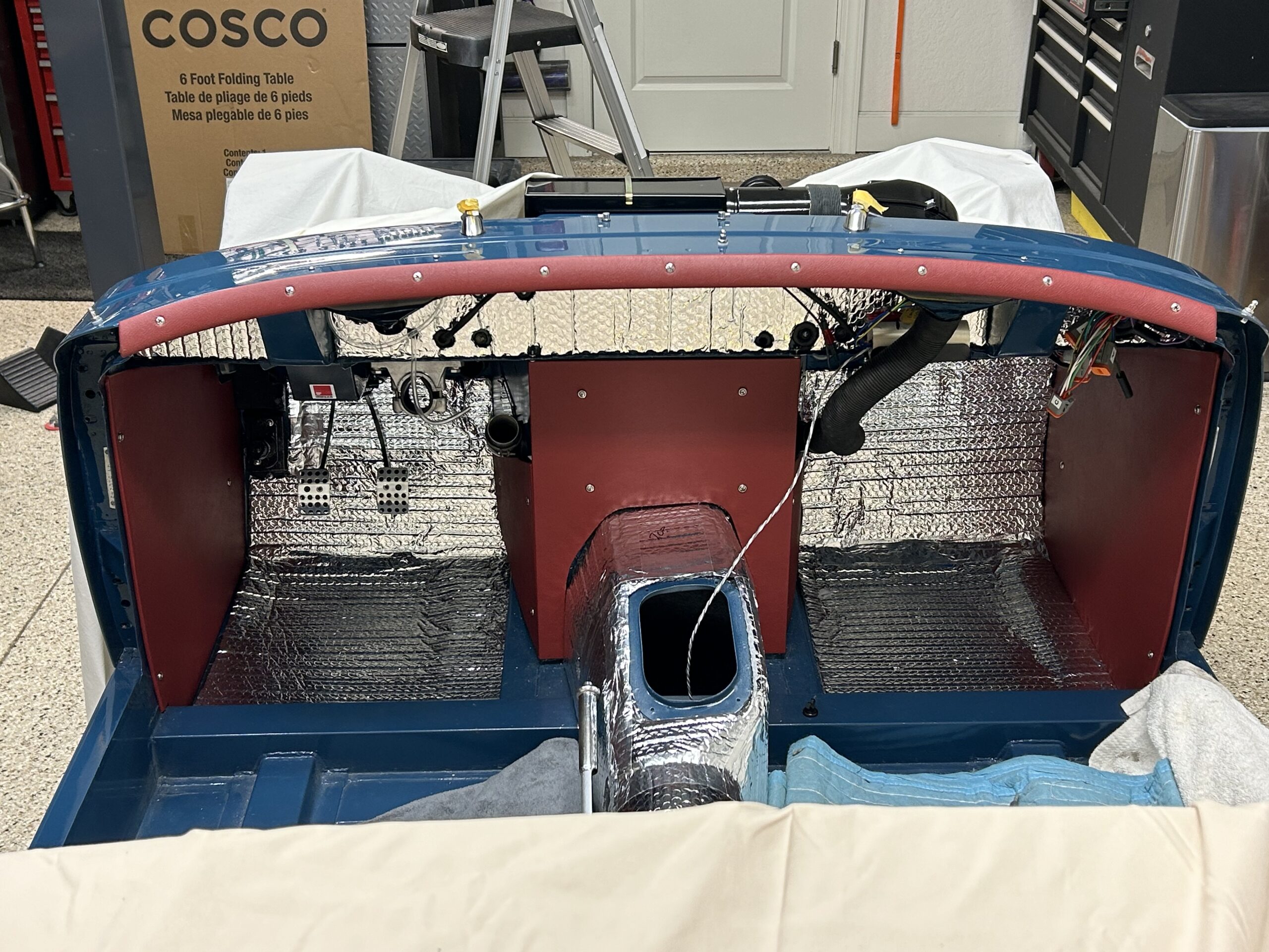
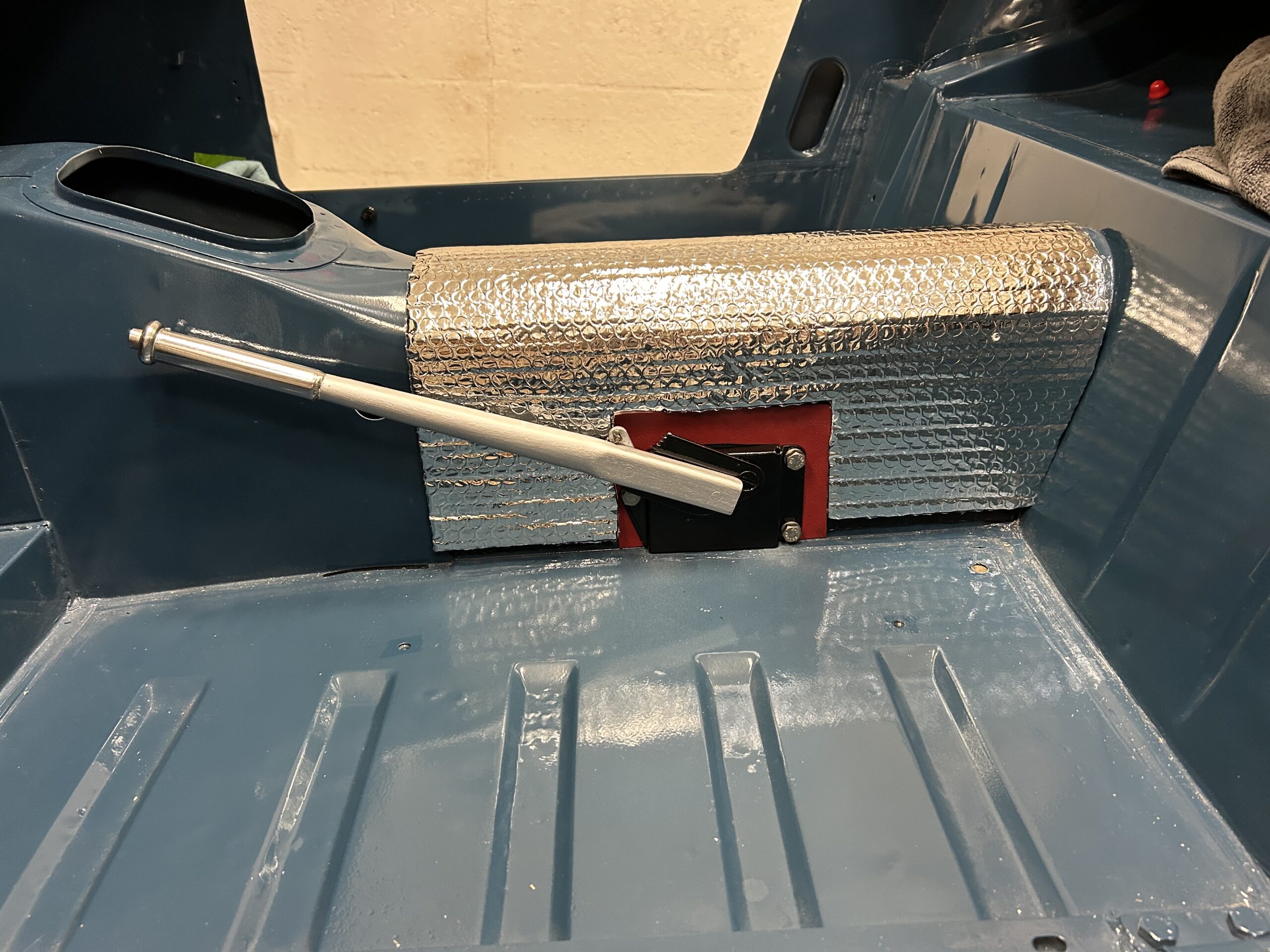
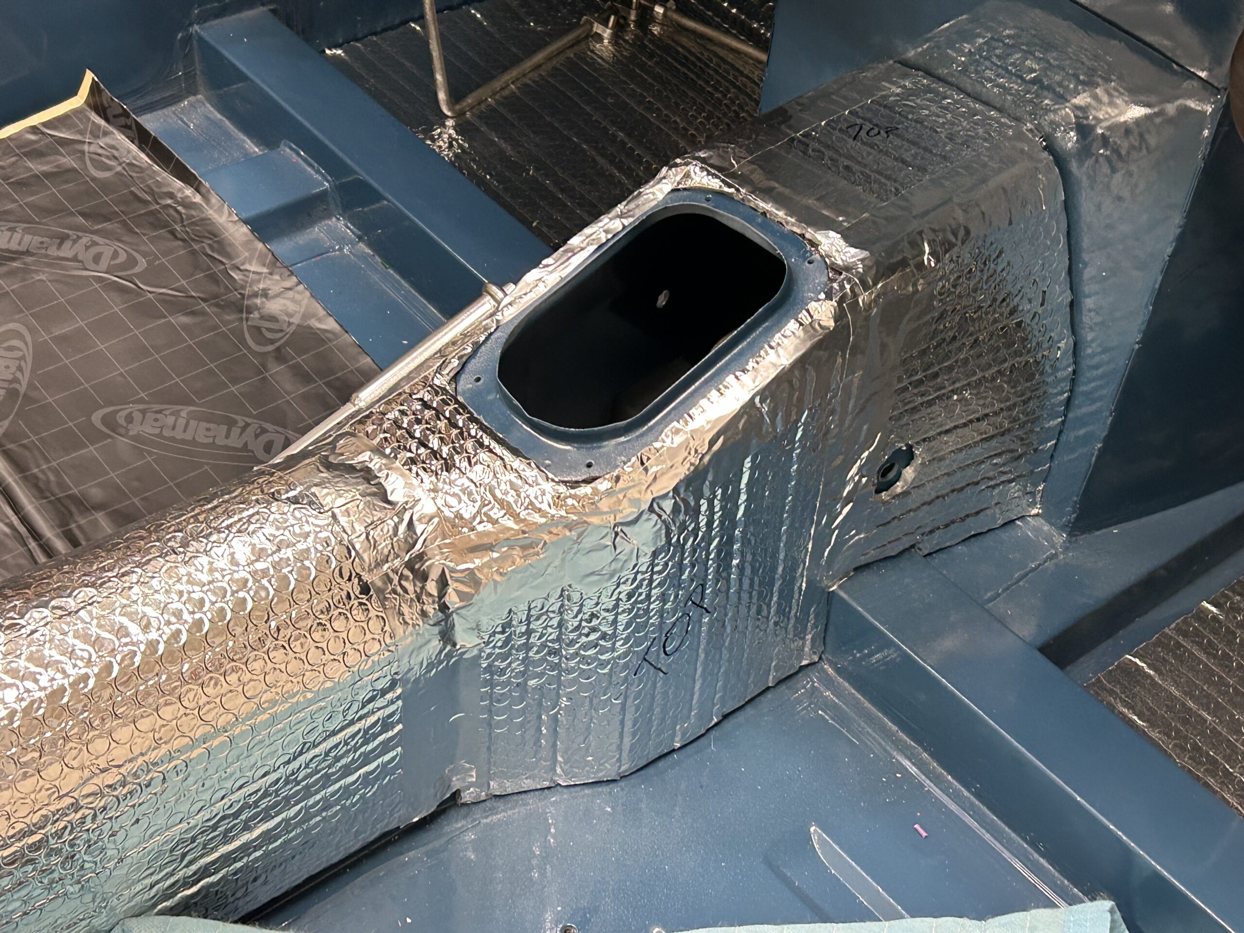
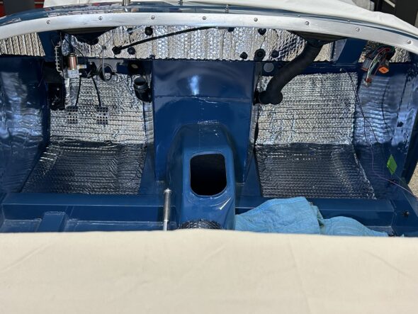
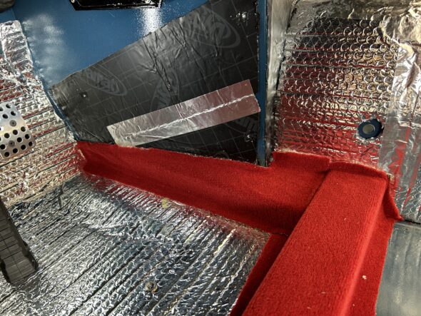
We then began the installation of the Dynamat Extreme and aluminum insulation throughout the interior. The first location was the driveshaft tunnel after we installed the handbrake.

Dynamat Extreme and aluminum insulation on propshaft tunnel
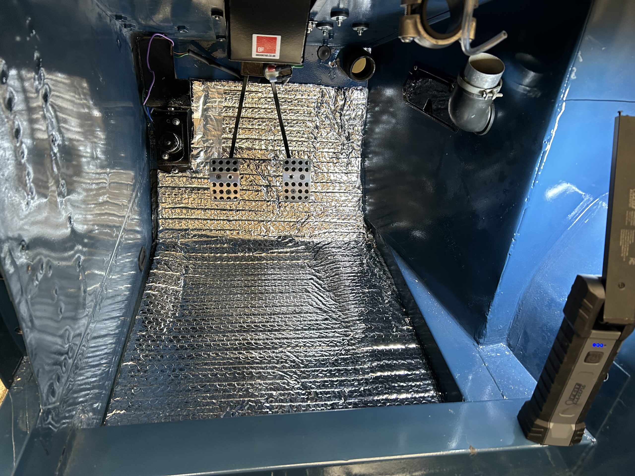
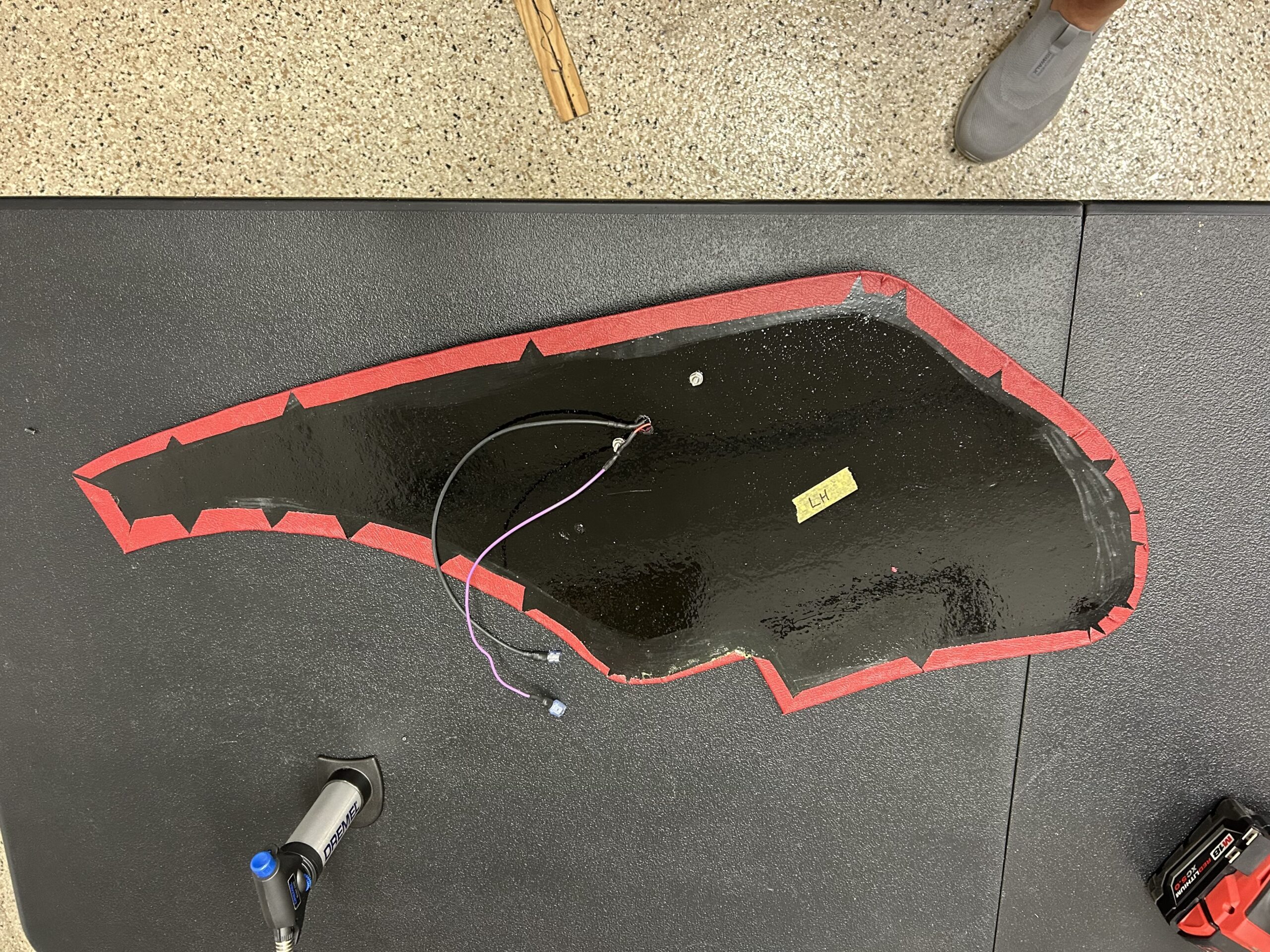
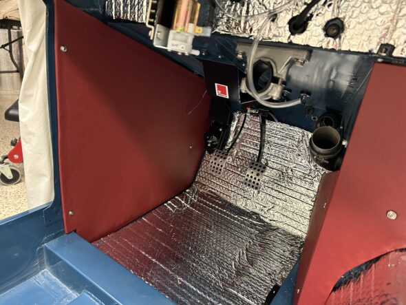
Then we moved to the floorboards in the footbox.
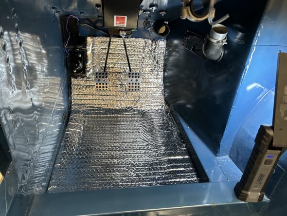
LH footbox insulation
Both sides
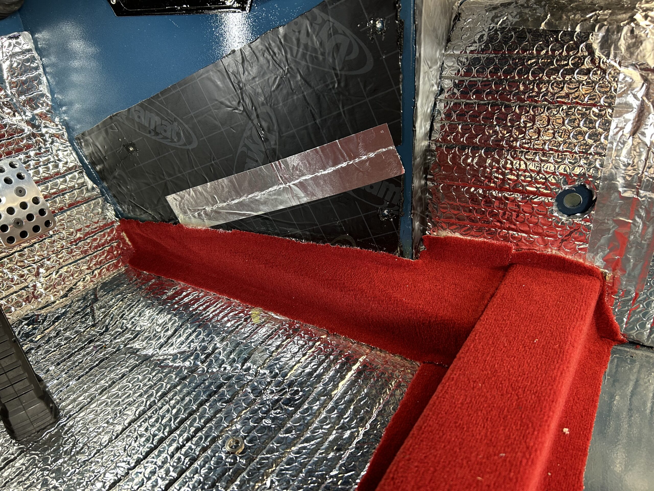
We tackled the gearbox tunnel next. It isn’t very large but lots of angles and curves so it took a while to complete.
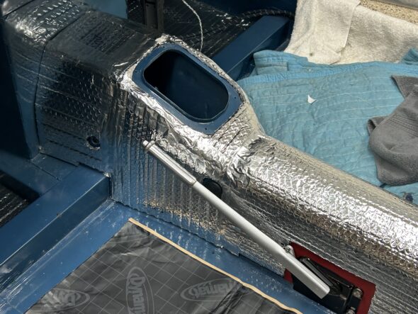
Gearbox Tunnel with Dynamat and Aluminum Insulation

Gearbox Tunnel with Dynamat and Aluminum Insulation
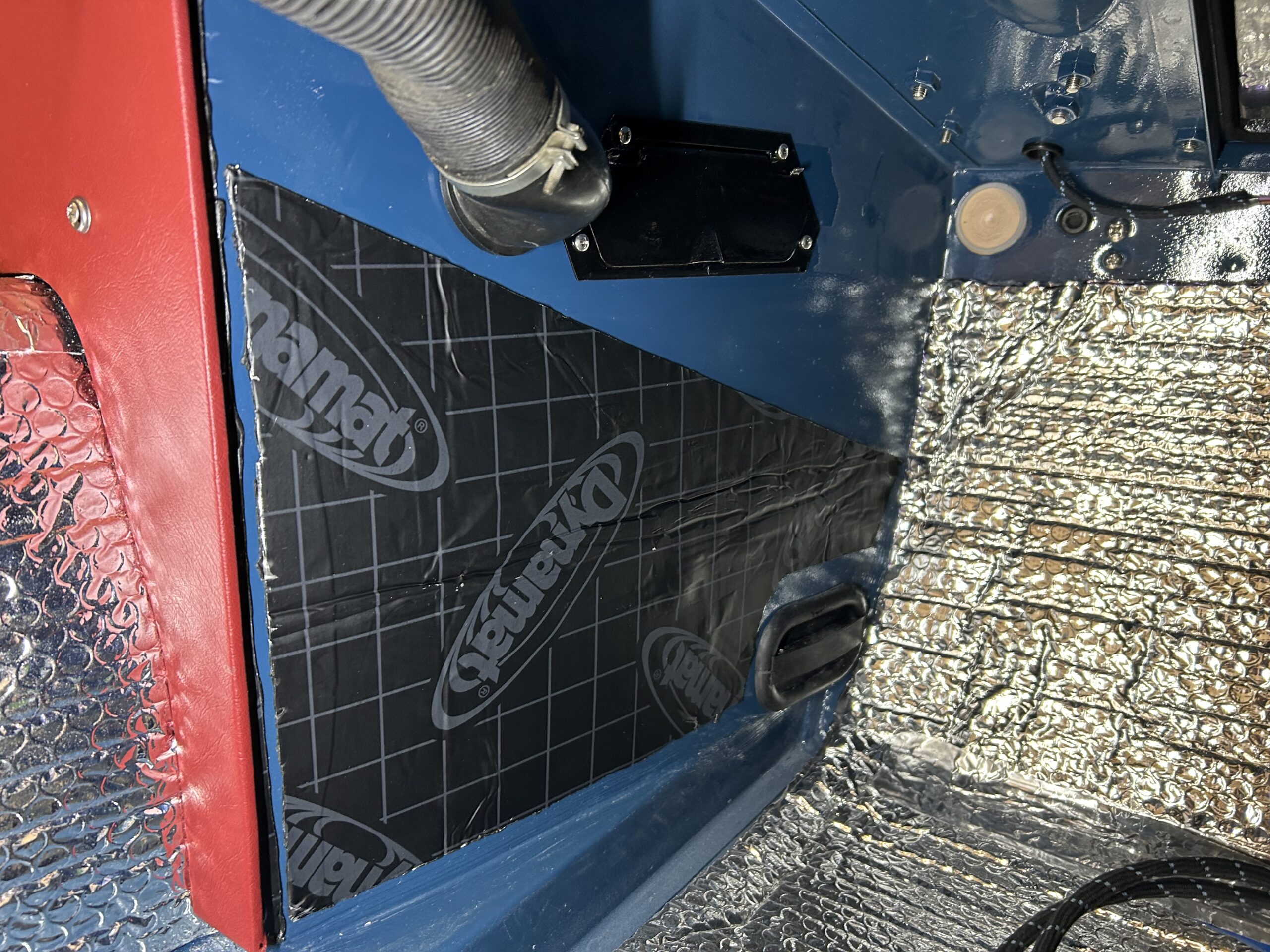
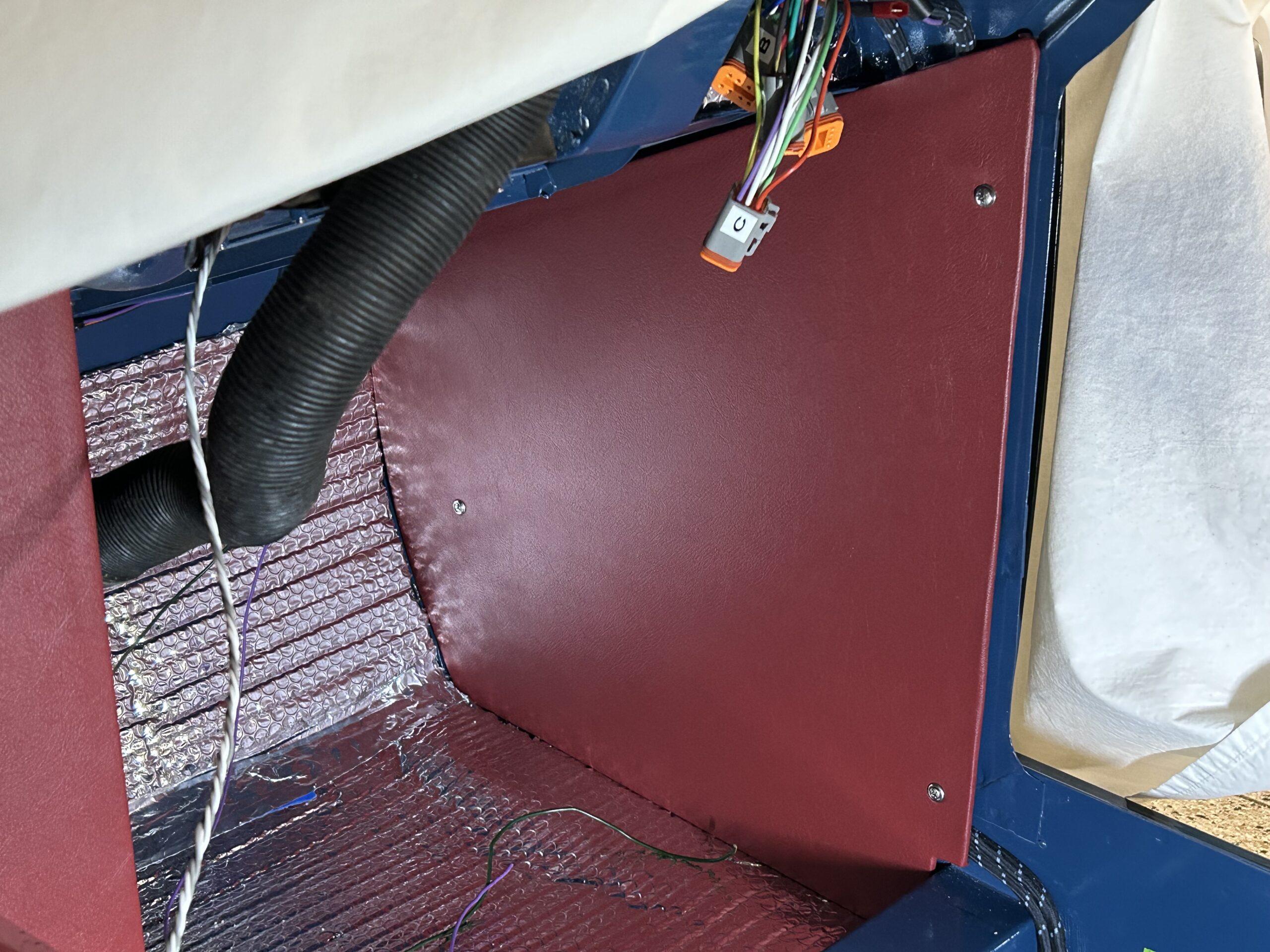
The next area to address was the box around the gearbox bell housing and the rear of the engine. This consists of three surfaces that are covered with upholstered panels. On these three surfaces we chose to use only Dynamat Extreme and to forgo the aluminum insulation. The concern was that we would not be able to get a tight fit with the intersection of the panels. The stainless steel finishing screws and trim cup washers were supplied by Bugeyeguys.com.
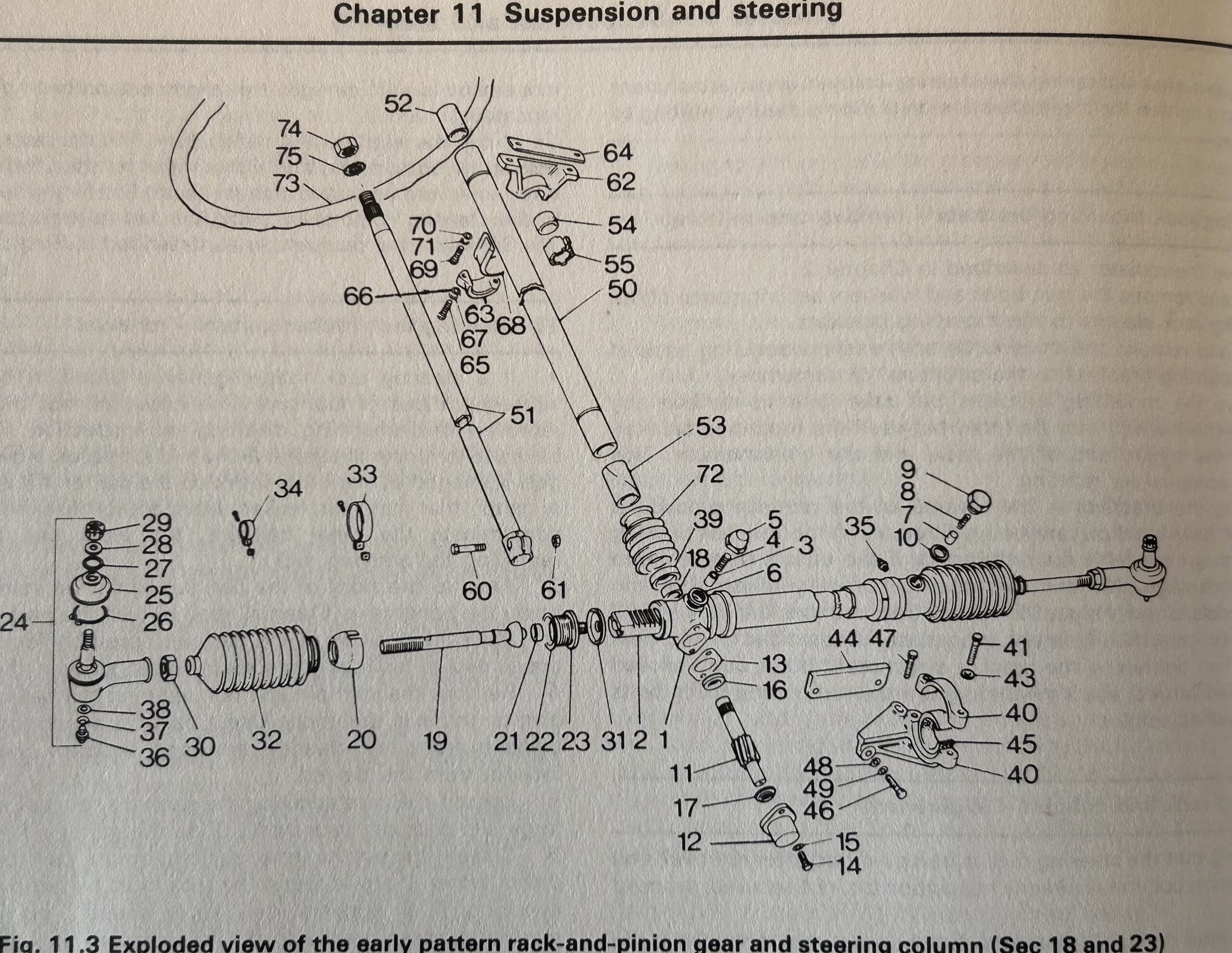
We installed the Dynamat and the upholstered panel on the front central face of the box first. The upholstered panels were sourced from BugeyeGuys.com. With the exception of the center panel over the gearbox cover, we had to remove vinyl, trim the plywood and re-glue the vinyl to obtain a proper panel fit.The door sill panels and the rear quarter panels required the most adjustment. The image below, although in black, not red, illustrates the components that come with the BugeyeGuys upholstered panel kit. Panels numbered 3,4,7 and 8 as stated required quite a bit of trimming.
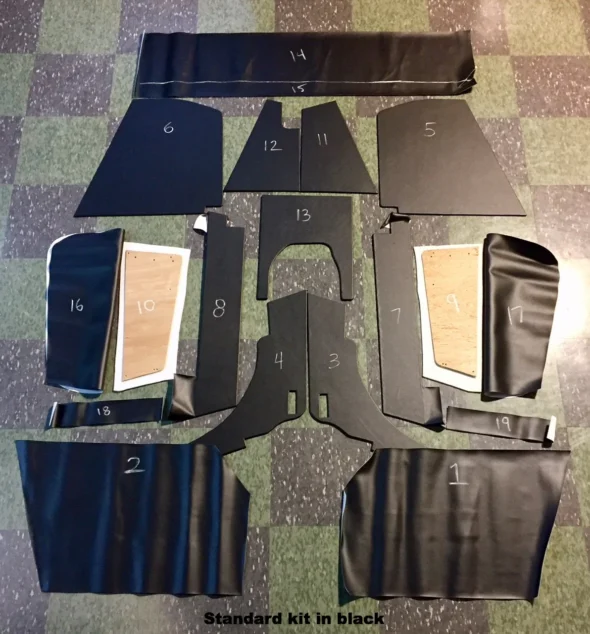
BugeyeGuys upholstered Panel kit
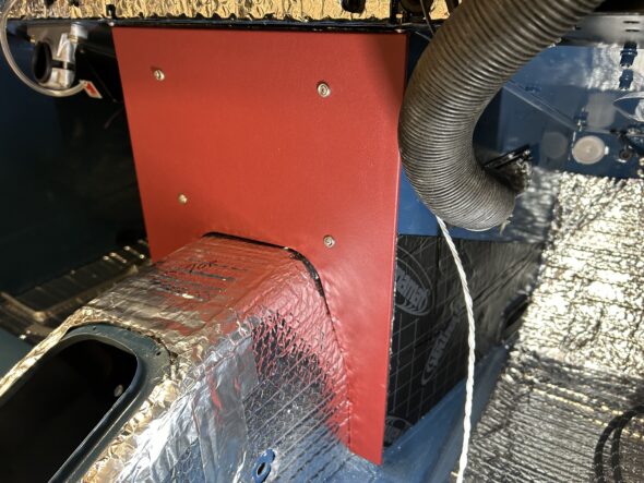
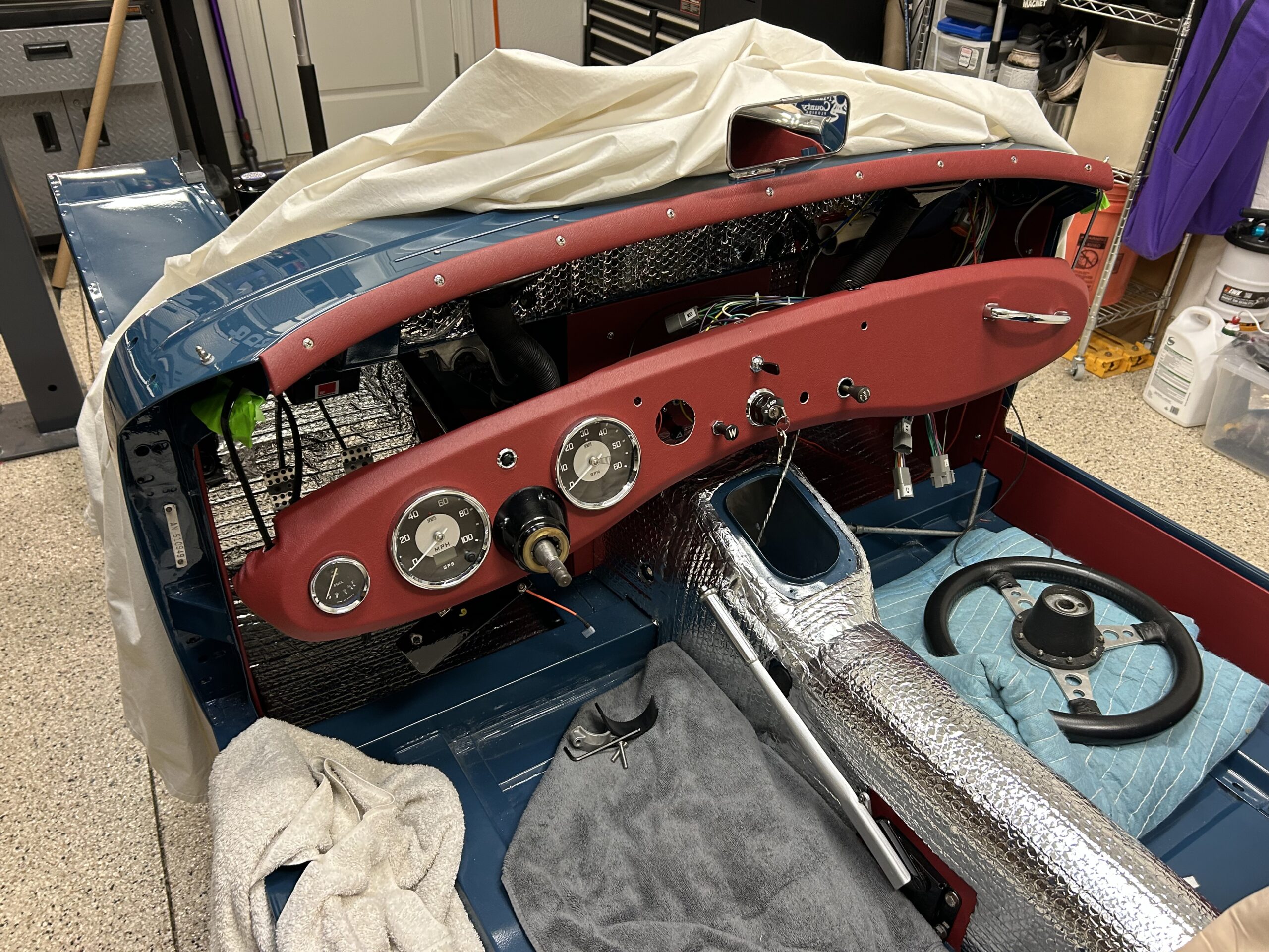
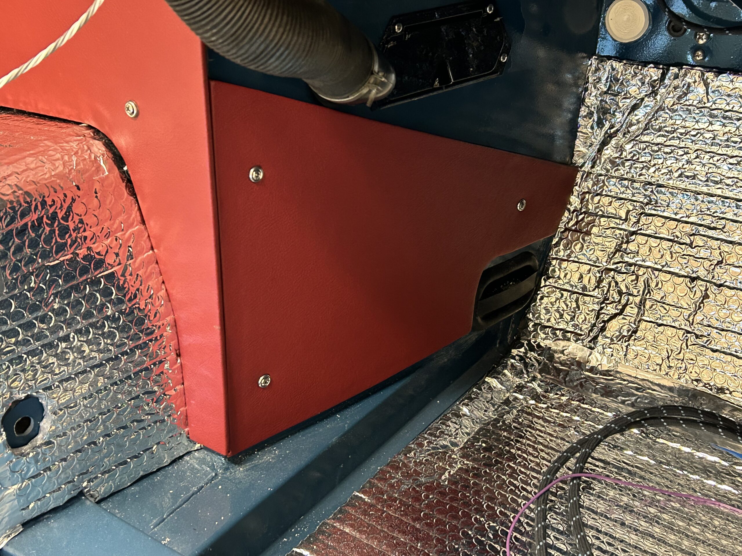
Center Panel Install
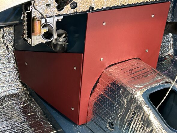
Then we worked on the RH passenger side:

RH Dynamat Install
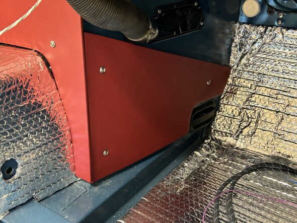
RH Upholstered Panel Install
The we moved to the LH driver’s side insulation and panel install:

LH driver’s side insulation install
LH driver’s side upholstered panel Install
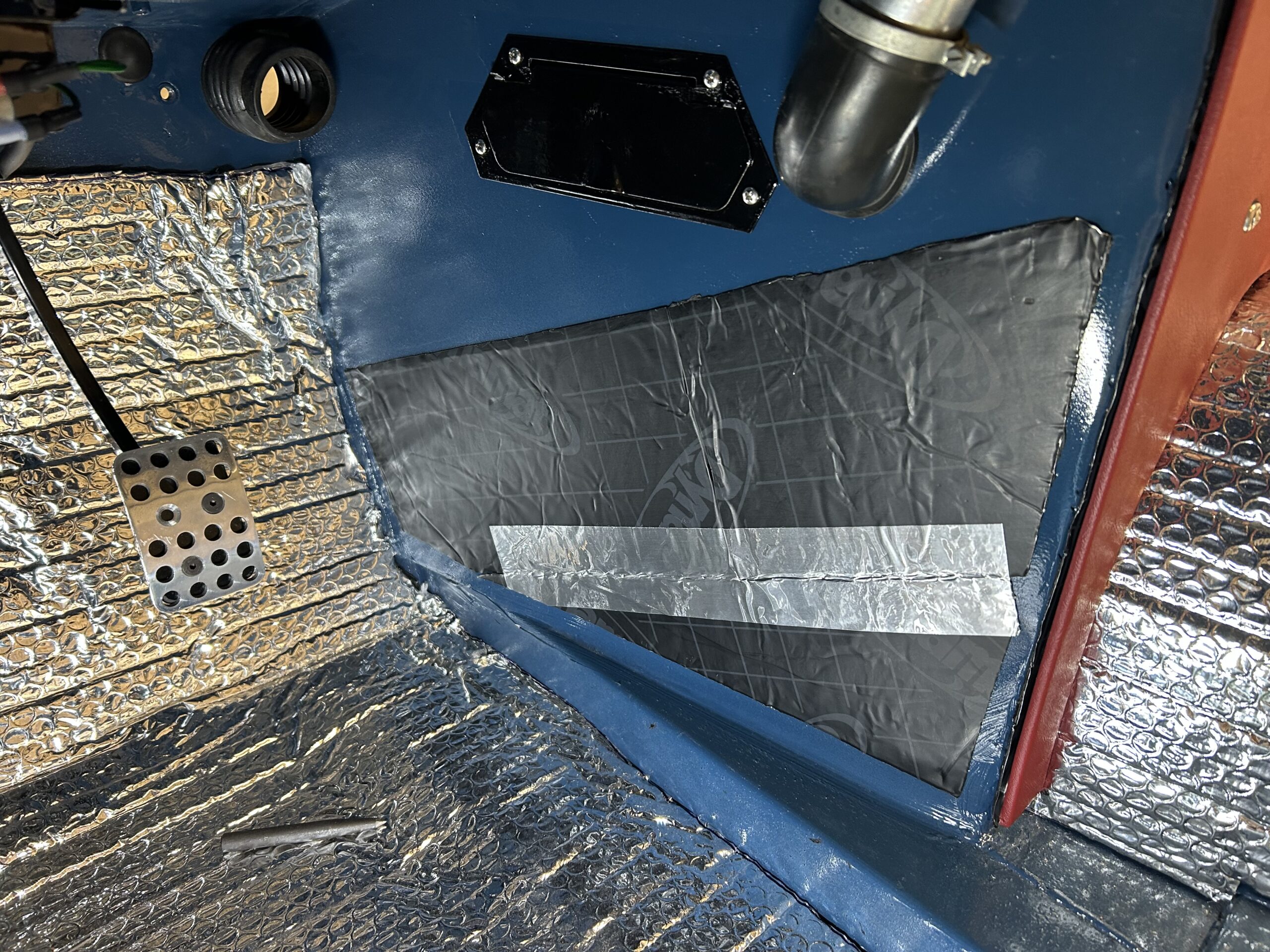
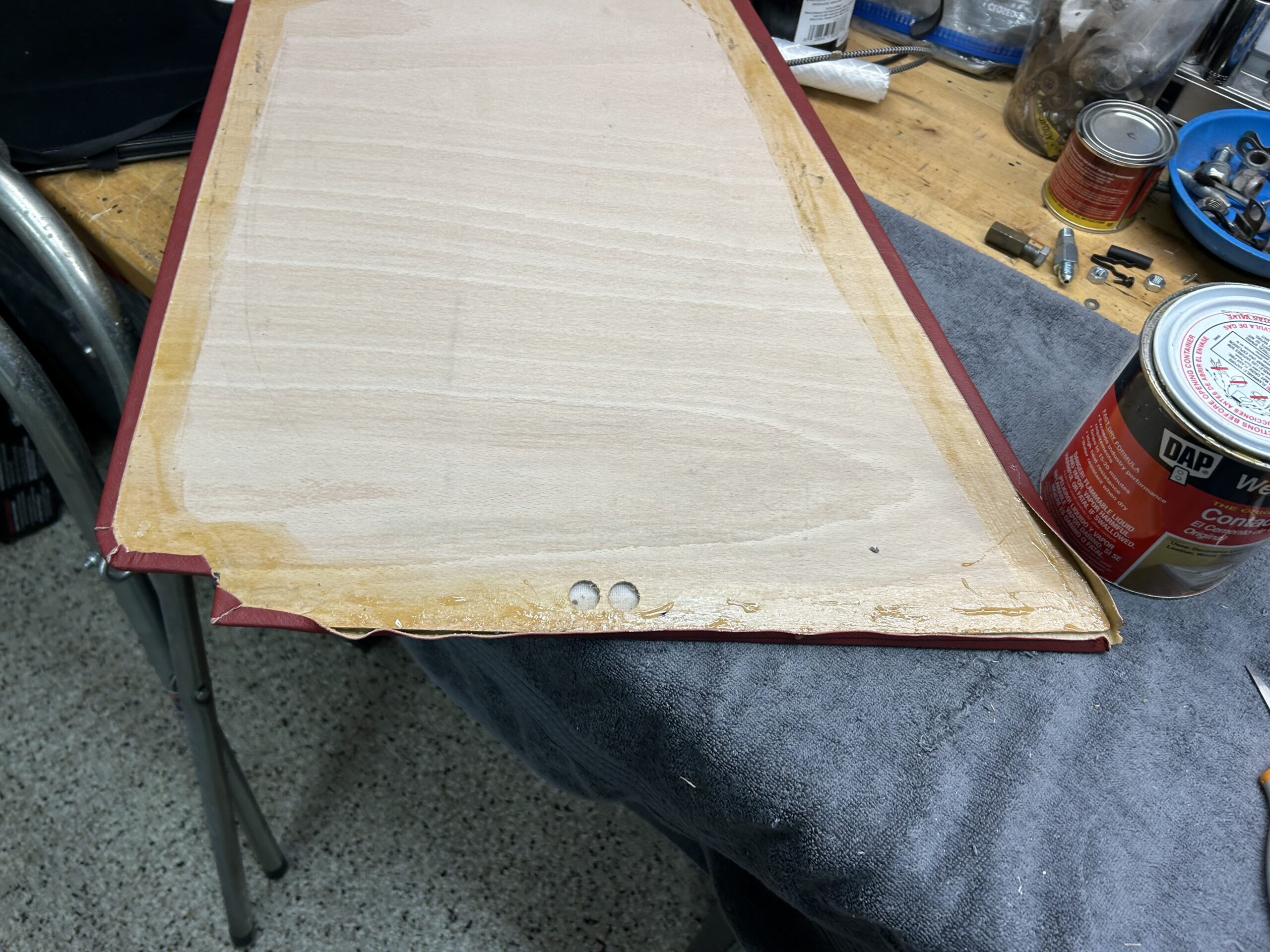
On both of the outside kick panels in the footwells we had to do some trimming to get a nice fit to the bristleflex seal. This involves pulling back the vinyl, trimming the board and re-glueing the vinyl.
Footbox panel modification
This is a photo of the modified panel installed. Very nice abutment to the bristleflex. The upper mounting screw is a #10 machine screw mounted to a rivnut that was previously installed.This was done on both sides of the car to prevent a sharp pointed self-tapping screw from protruding into the door cavity.
LH Footbox panel installed
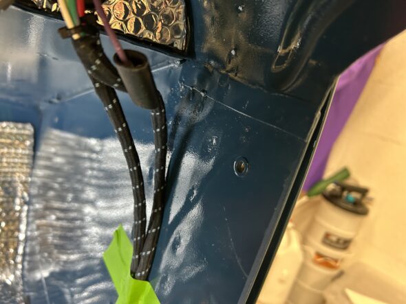
Rivnut for upper mount of the kick panel
Installing the RH kick panel was next. The wiring made this one a bit of a challenge but we got it in place.
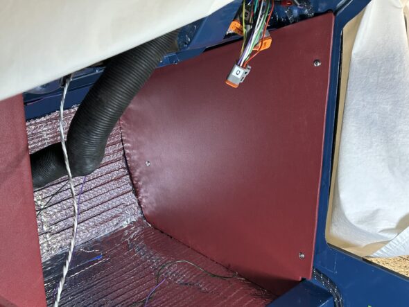
RH kickpanel installed
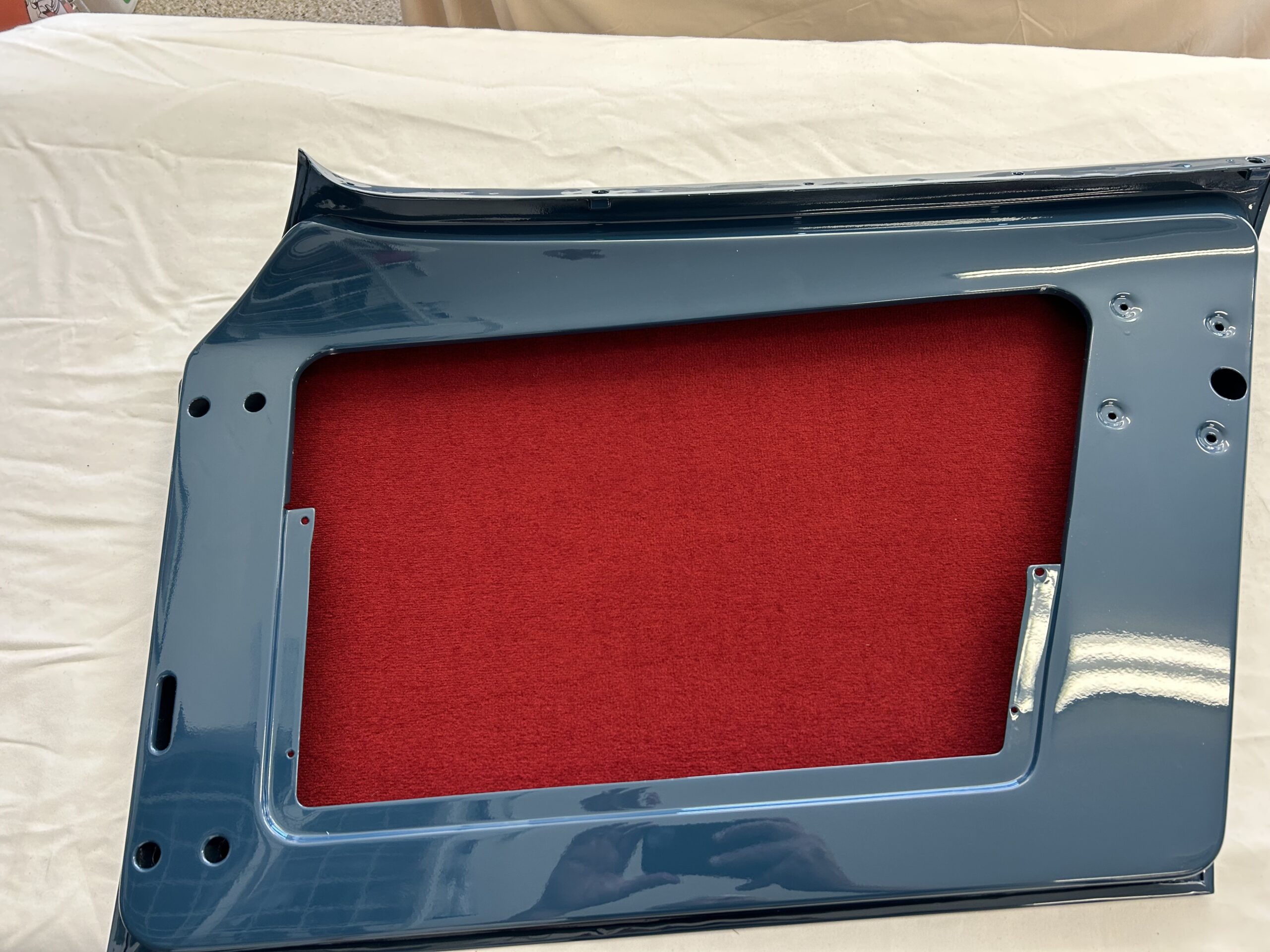
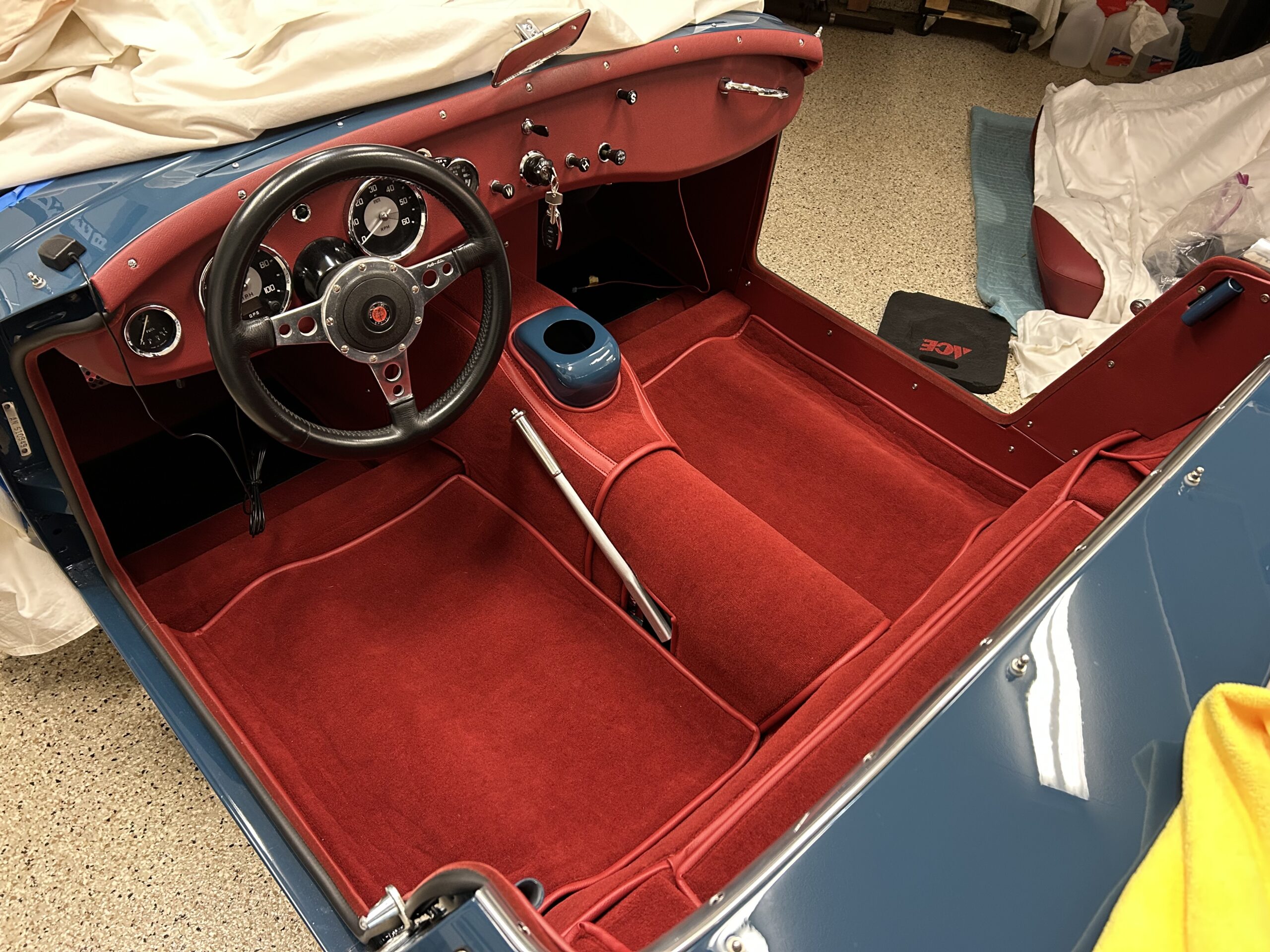
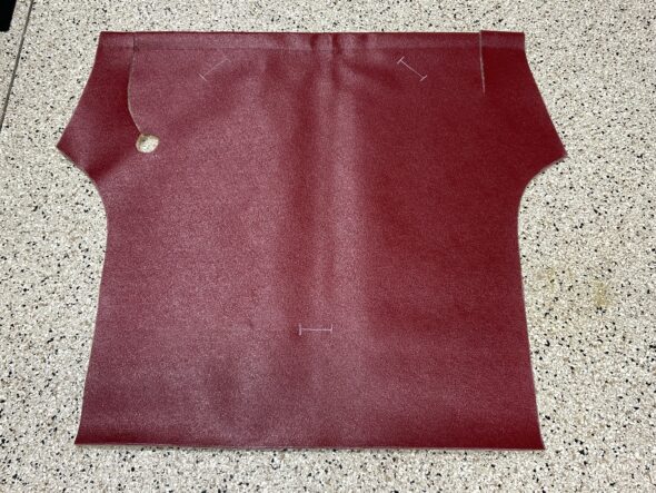
Following the installation of the front panels we turned our attention to the installation of the carpet. A number of vendors sell carpet kits for the Bugeye. We ordered sample material from several before deciding to go with the kit provided by Prestige Autotrim Products LTD. in the U.K. Their kit provides vinyl binding on most carpet pieces and where jute pads are used under the carpet they are sewn to the carpet. We opted for the high end carpet called Premium Feintuft Velour. We were pleased with the fit, color and carpet quality. Their kit DOES NOT include carpeting for the trunk or boot space in the car.
The first task was to glue the small carpet sections that cover the chassis cross bars in front of the seats.
Carpet glued to chassis box rails
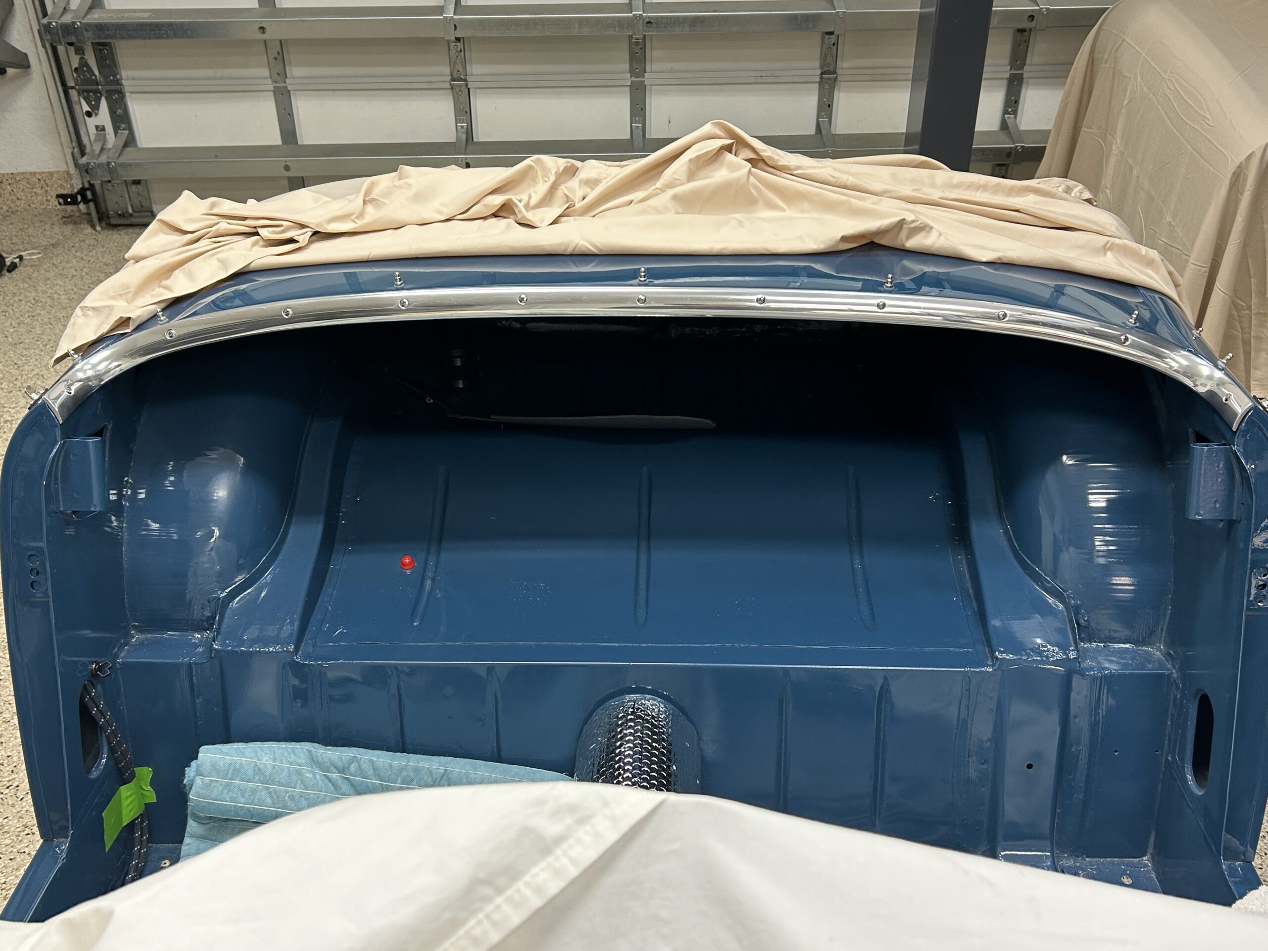
We then moved to the rear of the car. We ordered a trunk kit from Moss Motors. Their kit includes an Armacord floor mat and the two heavy cardboard side panels. We didn’t need the side panels but we could not find a vendor who sold the Hardura floor mat alone. We wanted Hardura, rather than carpet, because we believed that it would hold up better – particularly with a spare tire resting on it. The Hardura material does have a shallow jute backing. The leading front edge of the mat was glued to the floor. The hole for the fuel filler pipe was enlarged and the chalk marks locating the floor staples for the spare tire straps were cut. The mat proved to be a near perfect fit and did not require trimming. Installation of the mat is shown in the video associated with this post.
Trunk Floor Mat
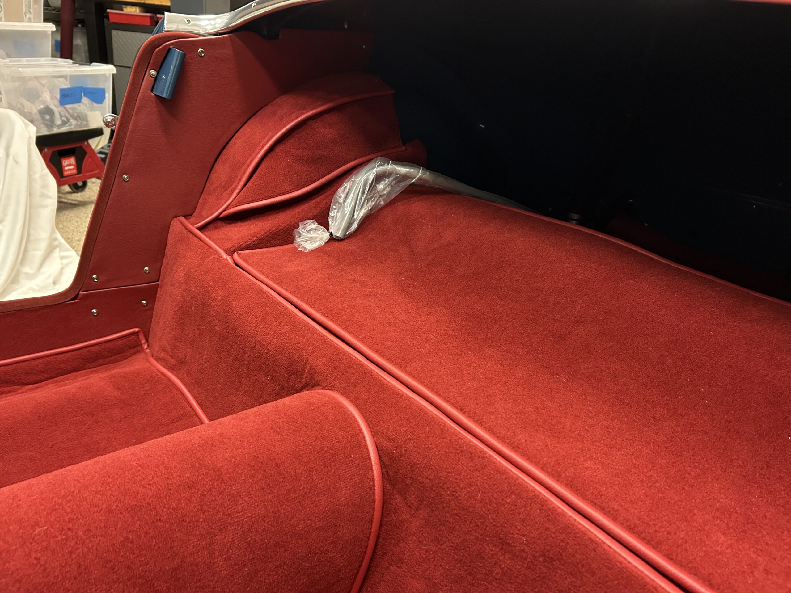
Next we glued several of the rear carpet pieces in place. Carpet pieces #1 and #2 were glued first, followed by pieces #3 and #4. Carpet section #5 has a 2″ piece of vinyl along its top edge that is glued to the floor. All of this is shown in the video. We will add some floor snaps to the carpet sections #5 and #6 to keep them in position. The two pieces of carpet that cover the gearbox cover or tunnel will also be held in place with snaps.

Rear carpet installation
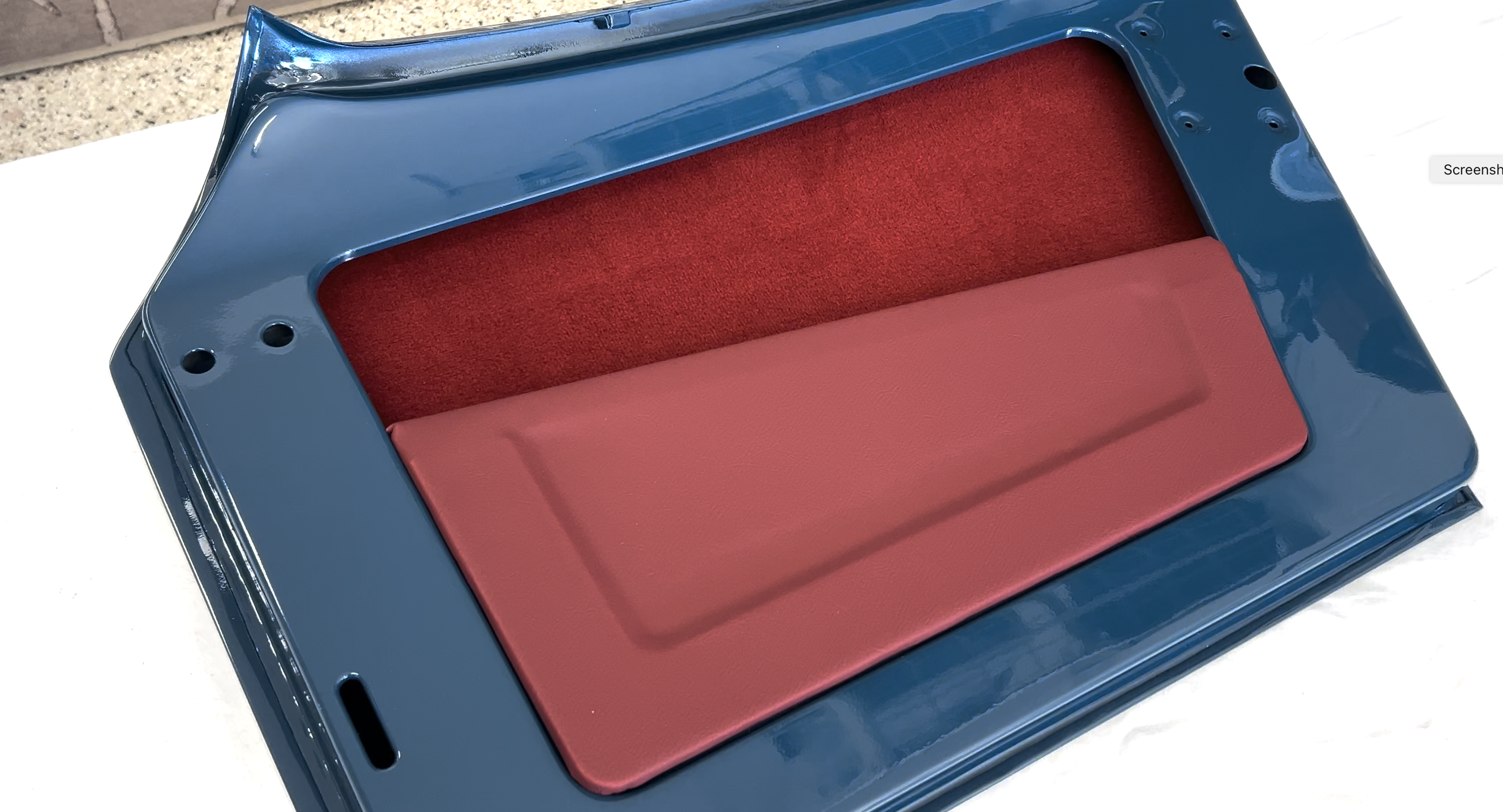
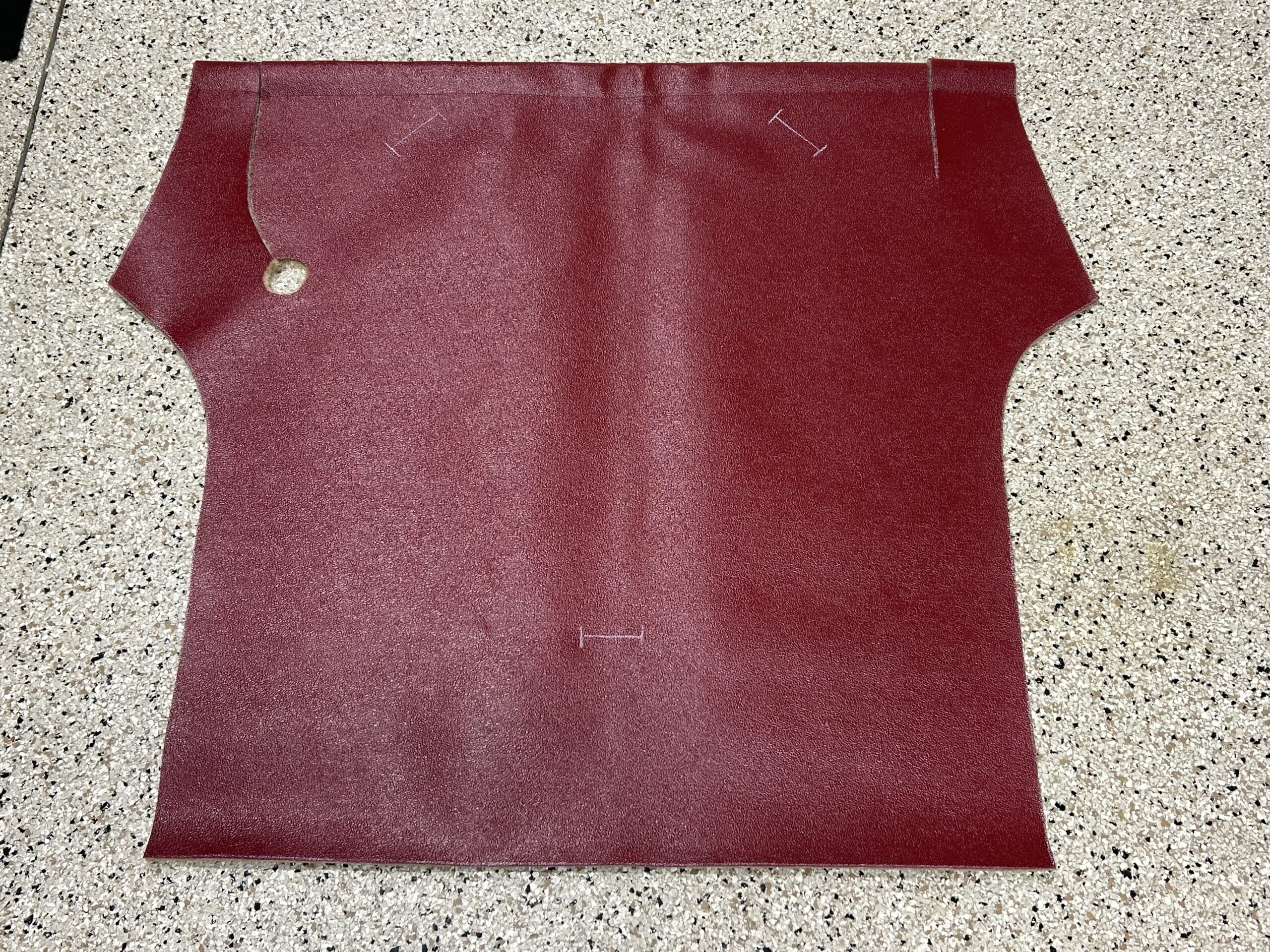
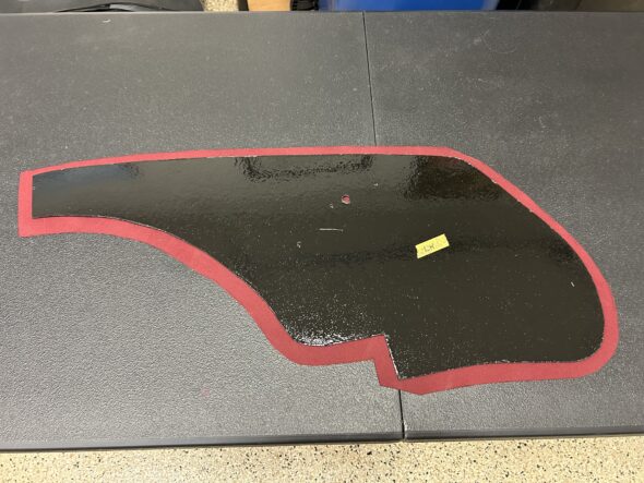
We then returned to fitting the upholstered door sill panels and the rear quarter panels. Again, details of this procedure are best described in the video. The rear quarter panels fit too tightly around the tube for the soft top frame, so those holes needed to be enlarged. As best we can tell, both quarter panels are also too short and consequently did not butt up against the sill panels. A half inch gap was left between the two panels. So, we decided to make our own door sill panels and included a raised portion to permit a nice fit between the quarter panel and the sill panel. In the image below, the section of the panel to the right of the blue line was added.

Modified door sill panel
We ordered a product called cowl board, which is a waterproof fiberboard material, from Automotive Interiors and Accessories. Just to add a little stiffness and additional waterproofing, we painted the material with POR-15 before glueing on the new vinyl. The vinyl was purchased from Geoff Chrysler at Rightway Heritage Trim and while it is not a perfect match to the vinyl used on the panels purchased from Bugeyeguys, it is damn close.
The photo below shows how the sill panel and the rear quarter panel now fit. Much, much better! The panels will look better once screwed into place.
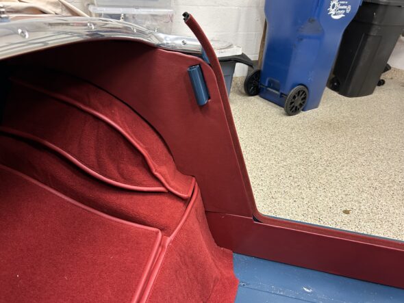
Quarter Panel and Sill Panel Fit
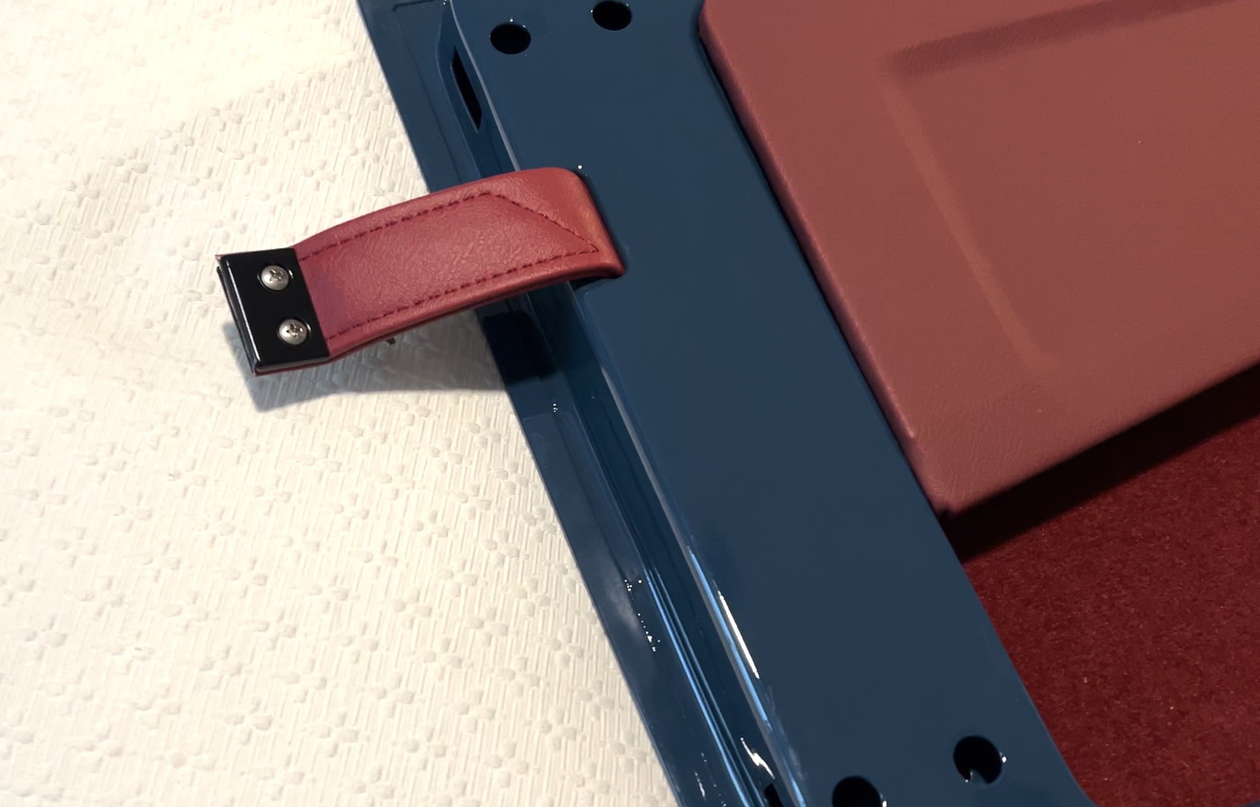
As can be seen in the photo above, there is a door seal that is part rubber and part fabric that serves as a trim finisher as well as a weather seal for the interior. The fabric portion of the seal has “U” shaped steel-braided “jaws” that grab the door sill lip to fit tightly in place. The quality of available door seals has diminished over the years. In many cases the steel “jaws” have been replaced with aluminum that is not effective in gripping the door lip. Martin MacGregor, owner of MacGregor British Car Parts, has sold a product called Bristleflex that maintains the steel grip and has a beautiful fabric finish. We think we may have purchased the last set of seals in the color red that he has manufactured and he is currently ((as of October 2024) attempting to sell his business.
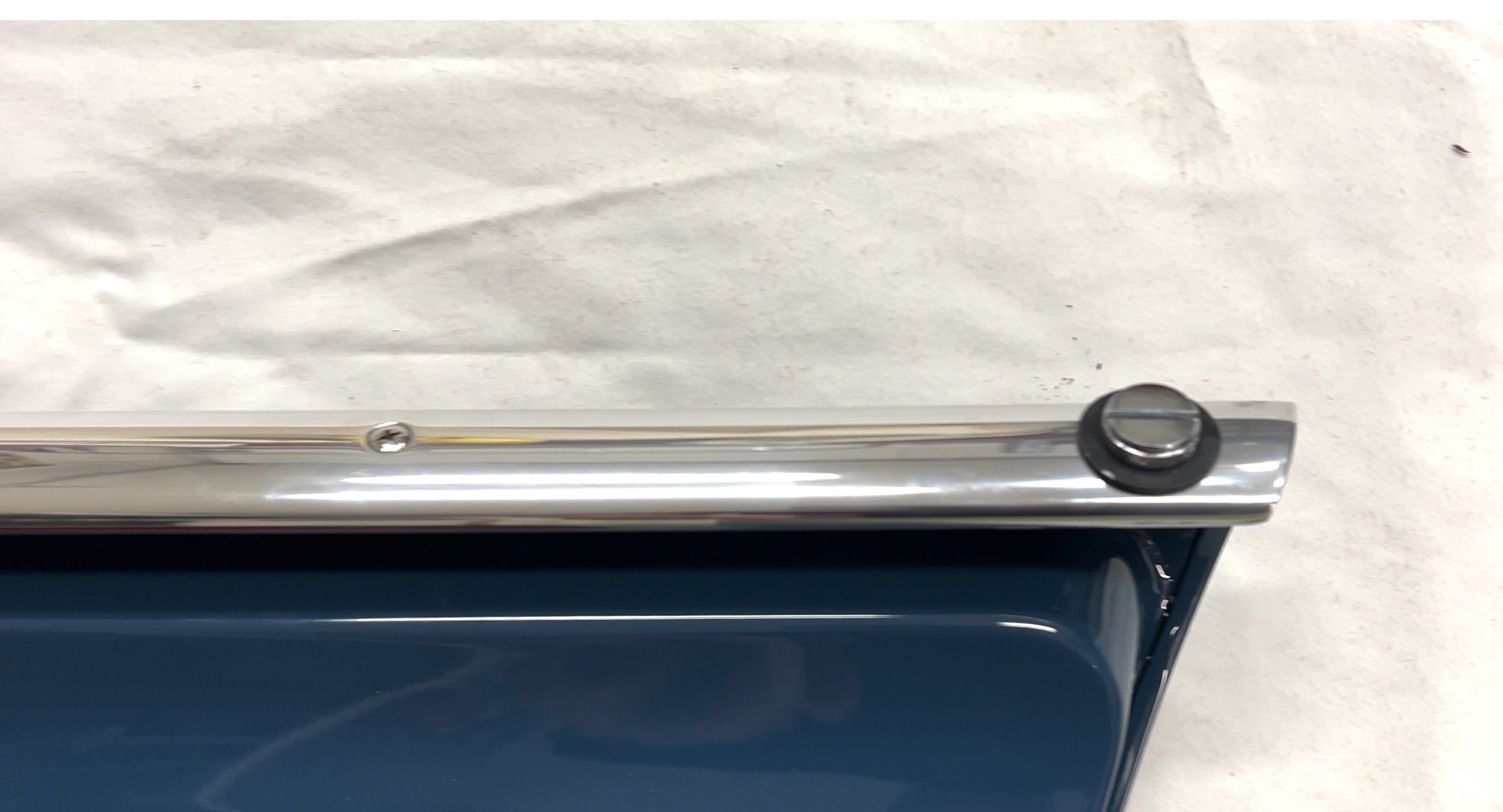
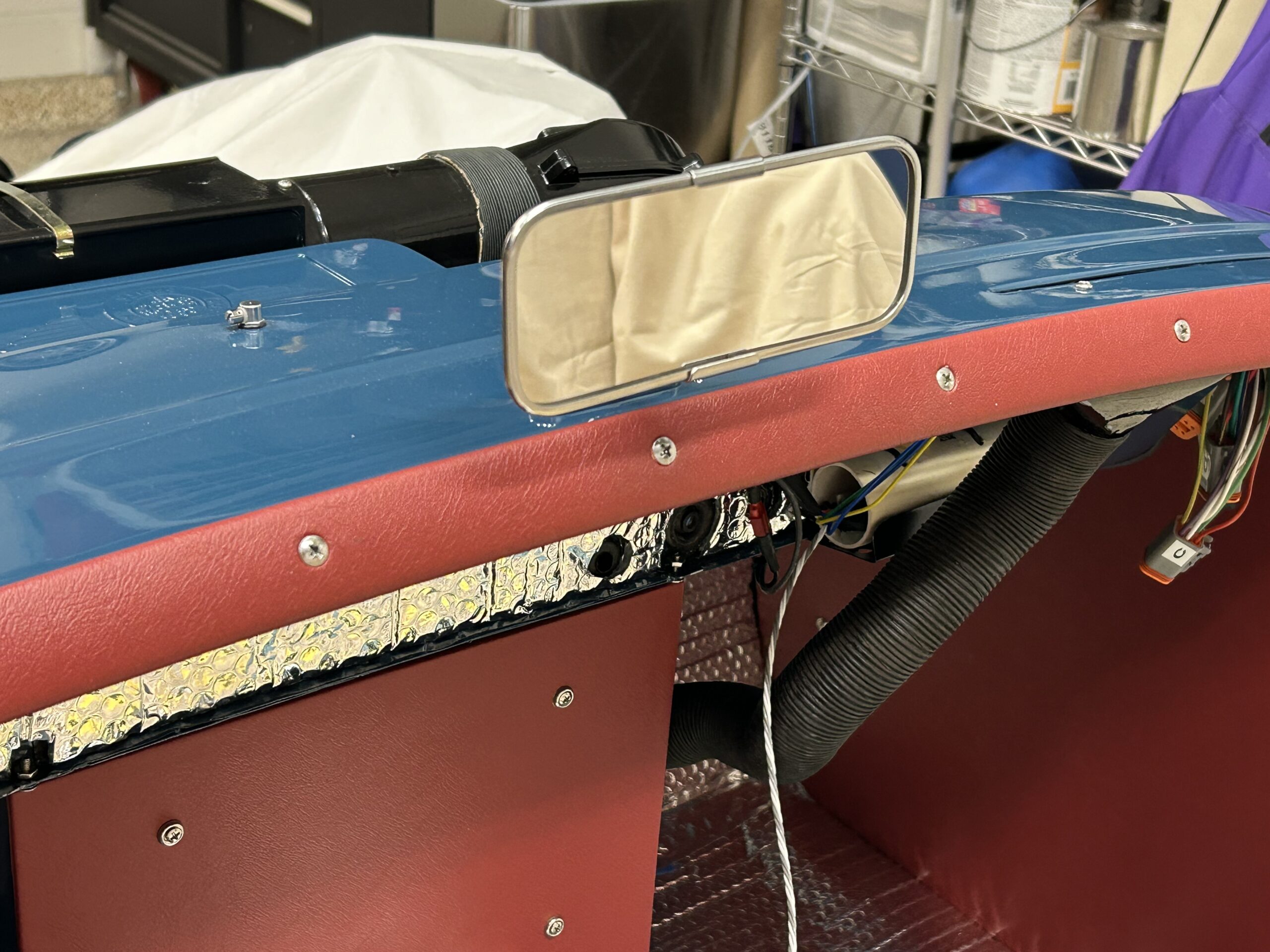
At the front of the car the Bristleflex terminates behind the aluminum cowl trim with an aluminum “P” clip.
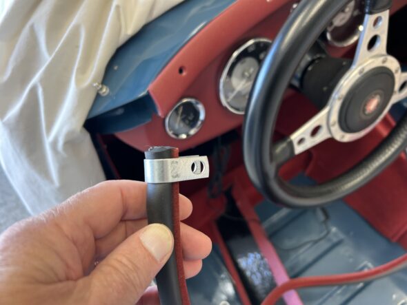
Bristleflex “P” clip attachment behind the Cowl Trim
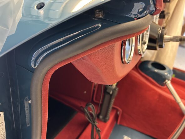
Front Bristleflex Installation
At the rear, the Bristleflex door seal terminates behind the rear quarter panel. We installed the Bristleflex and secured both ends before the sill panel and rear quarter panel were attached with screws. This was done to ensure a tight meeting of the bristle flex with the edge of the panels.

Door sill panel and rear quarter panel installed

Rear Quarter Panel Installed
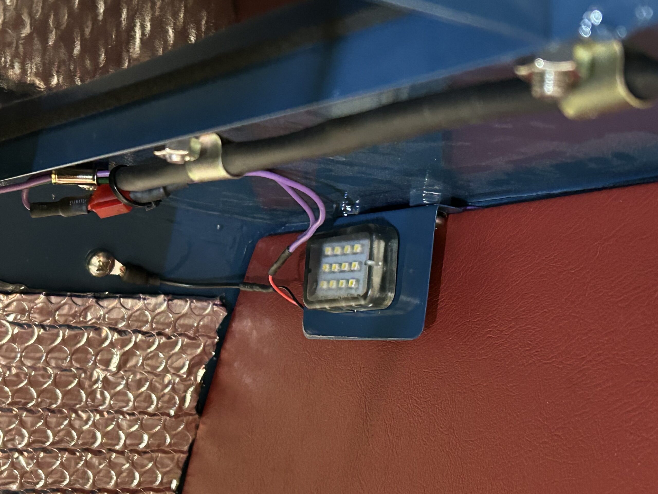
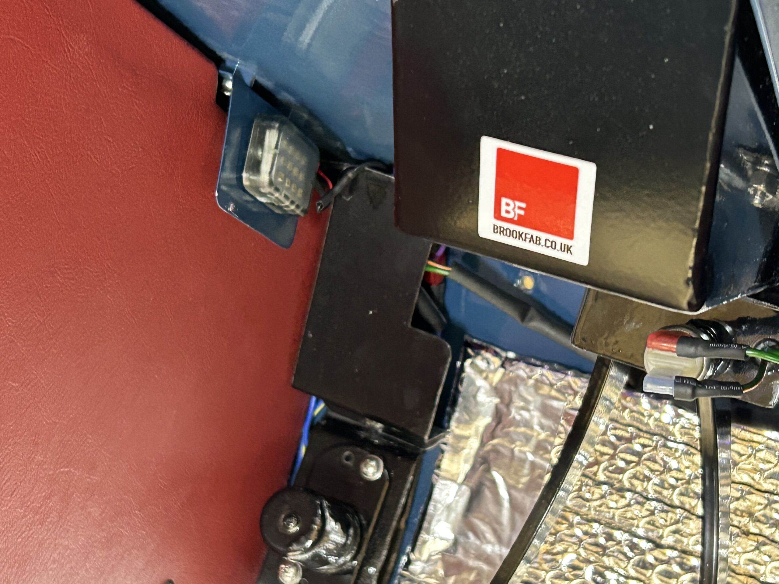
The last panels to cut, upholster and install were the boot side panels. We again painted the panels with POR 15 to enhance water protection and to add stiffness to the board. Each of these panels are mounted with two #6 sheet metal screws with trim cup washers. The courtesy lights we reinstalled in the panels and both were them mounted to the car.
Boot trim panels

Boot trim panel with courtesy lamp installed
Installing the carpet snaps in the car and carpet was our next step in the completion of the interior. The snap consists of three pieces, the fastening ring with three tabs, the female side of the snap and the male side of the snap as seen in the photo below:
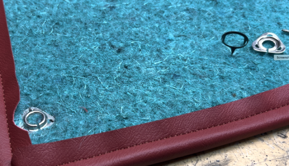
Carpet Snap installation
Installing the snaps was complicated because we already had dynamat and aluminum heat insulation in the car. We cut away and removed the insulation where the snaps were located and we added couple of savers behind the male end of the snaps.

Insulation removal
This is what the finished product looks like:

Carpet Snaps Installed
Bugeye Restoration Video Episode Eighty-three covers the work done with the interior insulation and panel installation to this point and it’s content is listed below:
https://vimeo.com/1028961169/ae3206c6d1?share=copy
0:00 – Cleaning floorboards
0:20 – RH side blanking screws
0:39 – Dynamat Extreme installed
1:01 – Aluminum insulation installed
1:30 – Insulation on gearbox tunnel installed
1:35 – Dynamat Extreme insulation on gearbox tunnel
1:52 – Aluminum insulation on gearbox tunnel
2:22 – Engine surround insulation and panel install
3:53 – Outside footbox panels installed
5:46 – Carpet installation begins
7:10 – Boot mat installed
8:49 – Rear bulkhead carpet installed
10:19 – Rear Wheel Arch carpet
10:47 – Rear carpet installed
11:15 – Door sill panels
14:28 – Rear Quarter Panels
15:27 – Bristleflex installation
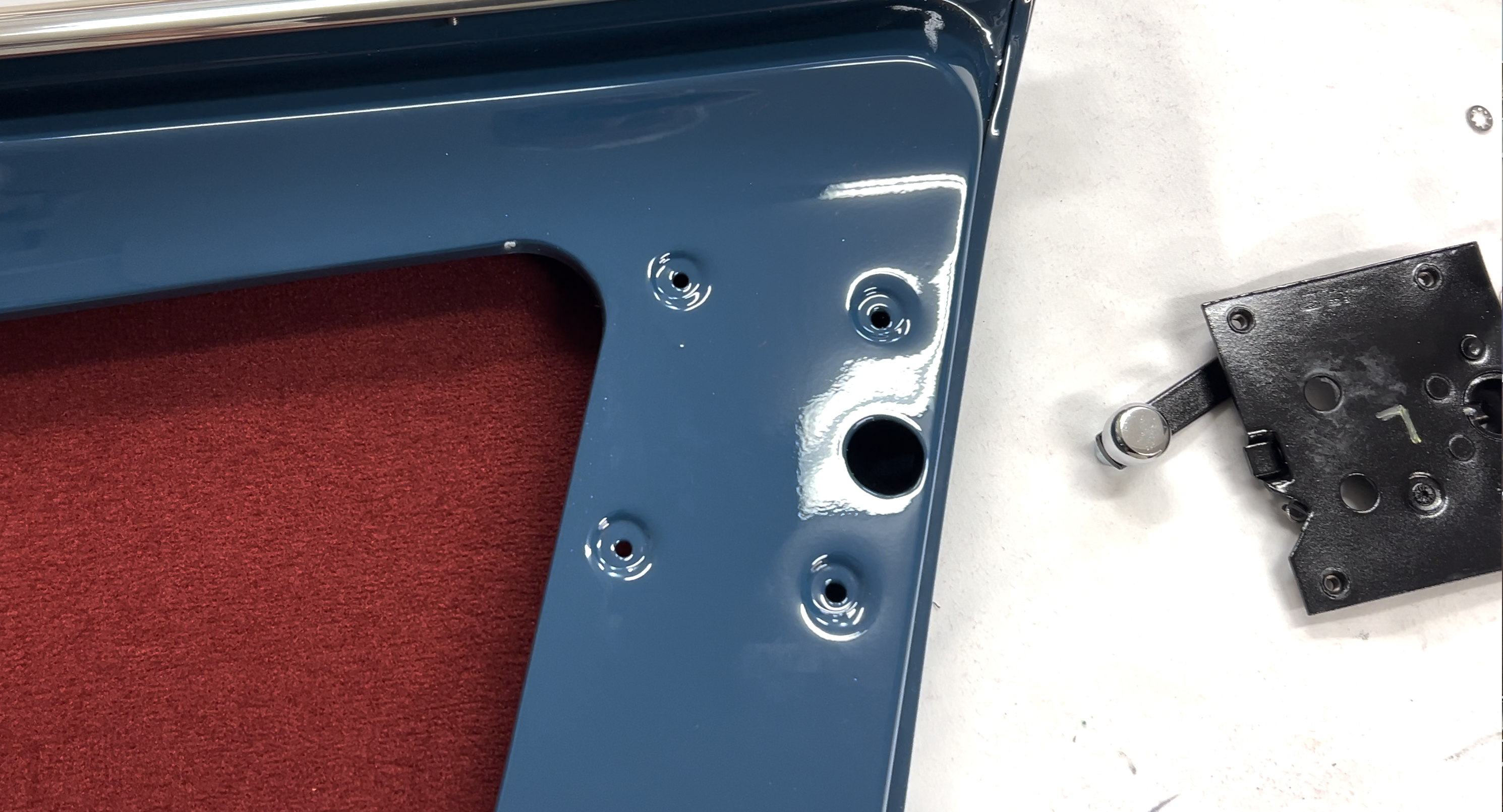
17:37 – Door Striker Installation
18:16 – Door Sill and rear quarter panel final installation
19:28 – Boot Trim panels
20:36 – Installing carpet snaps
26:36 – Adjusting the door seal to fit the soft top frame