Smiths Heater Refurbishment & Trial Fitting

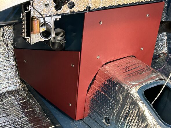
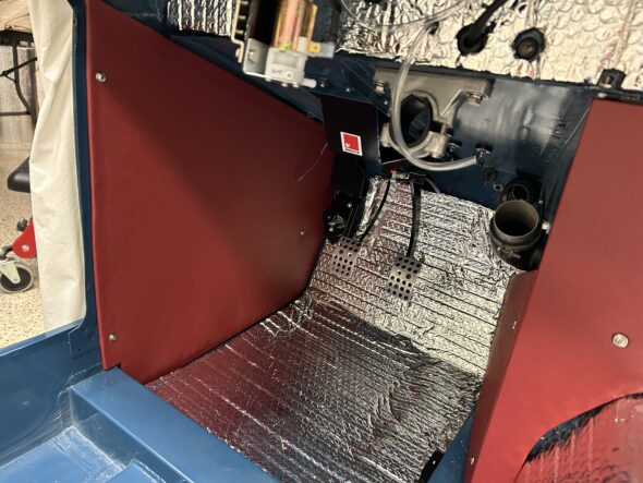
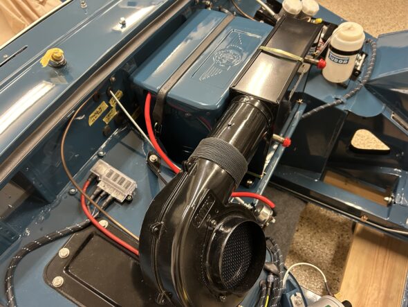
In a Bugeye engine bay, the Smiths heater box and blower are quite prominent so it is important that in addition to functioning well, they also look good! This Episode Forty-five video of the Bugeye Restoration shows the refurbishment process. The original plan was to use the heater box that was in the car, but in the end we decided to replace the box with a unit manufactured by Ashley Hinton in the UK. 

The matrix was flushed and checked for leaks and the blower motor was tested. The unit is now ready for installation in the car.

Bugeye Restoration Video Episode Forty-five: https://vimeo.com/860319039/8d4bcf8c4c?share=copy

Upon initial fitting of the heater box it was quickly evident that the heater box was sitting too low relative to the blower fan unit. In our case we are using a blower unit that was originally in a big Healey, the heater box as previously stated is a new reproduction made by Ashley Hinton and the previous owner installed a new battery shelf so it is difficult to say where the misalignment may have originated. Perhaps a combination of all three!

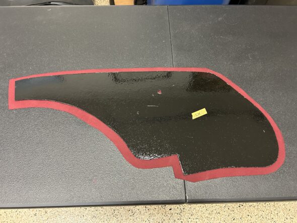
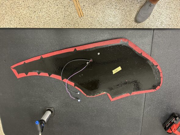
At any rate, we had some 1/8″ black ABS plastic sheet laying around the garage so we cut three pieces to size and then glued them together with ABS glue. We then used a 1 5/8″ drill hole saw and a saber saw to cut the air circulation hole in the center of the new shim plate. To this we attached 1/2″ closed-cell rubber adhesive-backed insulation and screwed the shim to the bottom of the heater box. We were then able to bring the components into alignment when mounted on the car.

ABS plastic shim

The dashboard heater switch was installed in the dash and connected to the blower fan. once connected to a 12 volt power source we were able to successfully test the switch and blower motor. 

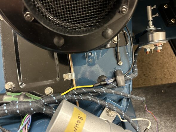
Finally, we installed a 10-32 nut sert into the RH engine bay valance to locate the large “P” clip for the heater/fresh air trunking. 

Bugeye Restoration Video Fifty-two shows the installation of the heater components in the car: https://vimeo.com/884518618/83d80549a4?ts=0&share=copy


Clean the Old Parts & Buy the New

Our experience is that we are almost always better off if we can clean and recondition a part rather than buying a new one. While we are fortunate that parts suppliers do an amazingly good job of making parts available for vintage British cars, it is too often the case that new parts have imperfections, are of lesser quality or just don’t fit. This post and its accompanying Bugeye Restoration Video Episode Forty-four covers the process of cleaning and acquiring parts.

This is the link to Episode Forty-four: https://vimeo.com/842617175/d7a040b143?share=copy

The list of items described is provided below.

0:00 – Handbrake

6:28 – Handbrake cable

6:53 – Demister nozzles

7:20 – Heater outlet door vents

8:05 – Steering wheel and column

9:22 – Steering column mounting bracket

9:30 – Steering bracket rubber shims

9:35 – Firewall dust seal for steering column

9:42 – Steering shaft

10:42 – Painted parts

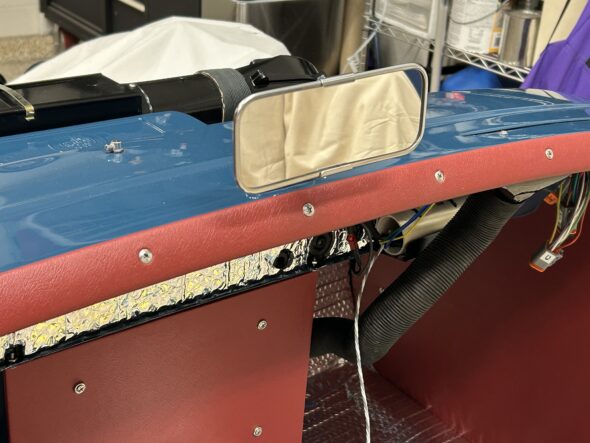
11:43 – Interior rear view mirror

12:08 – Accelerator Pedal modification

12:49 – Demister hoses and elbow fittings

13:16 – Rear Overriders

13:47 – Overrider brackets and braces

15:27 – Painted radiator support brackets

15:35 – Painted fresh air intake flange

15:40 – Bonnet rubber buffers

17:03 – Radiator coolant expansion tank

18:02 – Bonnet grille and retaining cables and brackets

19:28 – Bonnet hold-down bolts

19:50 – Wiper rack assembly


Restoration Disruption

We were plugging away on the new electrical system for the Bugeye (pun intended!) when by chance we happened upon a Facebook listing for the sale of a Bugeye body shell and bonnet that appeared to be in excellent condition. The car was purported to be a rust-free Arizona car and the bodywork, priming and etc. had been completed. Everything was ready for paint. No mechanical restoration had been undertaken – the opposite of our situation. We have most of the mechanical and electrical work done but the bodywork, paint and interior are still ahead of us. Unfortunately, we are in Florida and the car is in Michigan.

Michigan Bonnet

Michigan Chassis

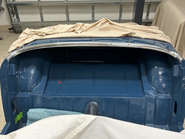
Michigan Rear Shroud

Michigan Underside

To make the proverbial long story a shorter one, the car checked out and we will be purchasing it around mid-June. Because garage space is limited we began with an immediate and total disassembly of the Bugeye to prepare for the arrival of the “new” car. We want to be able to move the old shell and bonnet out of the garage at the same the “new” car arrives.
As of June 1, 2023 everything has been removed from the car except for the front and rear suspension, the steering and the engine. The engine will come out this weekend and then the remaining components will quickly follow suit. A trolley has been built for the new shell so that it will be easy to move around.
The following Bugeye Restoration video episode forty-two covers the disassembly that has occurred since mid-April. In less than thirty minutes, two weeks of work is recorded for help with reassembly later. The list of items covered in the video is very long this time, but to make it easier to find a particular topic without having to sit through the entire video, the index is provided.

https://vimeo.com/832369002/c87fd61c10?share=copy

0:00 – Restoration Disruption explained

1:57 – Exhaust removal

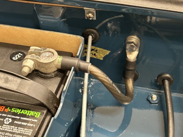
2:23 – Ground Cable from Chassis to Gearbox

2:32 – Rear Propshaft separation

2:39 – Draining Rear Differential, Gearbox and Engine Oils

3:05 – Battery, Battery hold down bracket and battery tray removal

3:15 – Battery cables from positive post to alternator and starter switch

3:33 – Battery ground cable

3:40 – Starter switch

4:01 – Ignition Coil

4:38 – Oil pipe/hose from engine to gauge

4:42 – Oil pressure/water temp gauge and capillary tube

4:58 – Heater hoses

5:05 – Heater Box 

5:38 – Heater/Battery tray

5:44 – I.D. number plate

5:57 – Carburetor and heat shield

6:23 – Throttle Cable

7:09 – Intake manifold and exhaust header

7:30 – Oil Catch can

7:39 – Breather hoses from rocker cover and timing chain cover

7:50 – Loosening engine motor mounts

8:31 – Gearbox mount bolts

8:45 – Gearshift cover, gear shift lever and additional gearbox mount bolts

9:47 – Master cylinders and pedal box

10:13 – Brake pipe from master cylinder to brake pipe union

10:28 – Wipers, Wiper rack, wheel boxes

11:26 – Windscreen washer nozzles

11:40 – LH Radiator support brace

11:52 – Rubber seal between body and bonnet

12:15 – RH pedal box blanking plate

12:25 – Assorted rubber grommets, and blanking screws/bolts

13:30 – Four rubber pads between bonnet and body

13:37 – Two metal block and rubber inner fender buffers

13:44 – Windscreen

14:18 – Exterior mirror 

14:38 – Interior rear view mirror

14:48 – Tonneau lift-a-dot posts (3)

15:20 – Demister vent nozzles

15:52 – Cockpit and door aluminum trim

16:04 – RH Door seal removal

16:25 – RH Door panel, carpet and latch assembly

16:47 – RH gearbox footwell panel

17:00 – RH Demister hose and elbow

17:03 – RH front floor carpet

17:10 – Slave cylinder access rubber bung

17:25 – RH heater vent door

17:33 – RH accelerator pedal assembly blanking bolts/screws

17:52 – LH door panel, seal, carpet and latch assembly

18:12 – LH vinyl panel below door and rubber grommets covering door hinge access

18:23 – LH gearbox footwell panel and carpet

18:36 – LH gearbox oil filler access bung

18:42 – LH heater vent and demister hose and elbow

18:57 – Accelerator pedal assembly

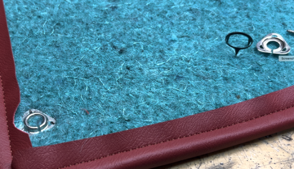
19:09 – LH carpet snaps

19:15 – LH front floor carpet

19:43 – Rear tonneau/Soft top fastener hardware on the rear shell

21:00 – Rear bumper overrider and bracket 

21:28 – Fuel Tank, filler pipe, rubber collar and hard pipe to fuel pump

23:15 – Fuel Pump

23:32 – Fuel pump mounting template

23:58 – “Sprite Flash” emblem for the boot

24:03 –  Spare tire and wheel

24:23 – Handbrake assembly and cable

26:30 – Propshaft Grease zerk access grommet

26:54 – Jacking rubber bung

Bugeye Restoration Video Episode Forty-three shows the removal of the engine/gearbox, the front and rear suspension, rear axle, steering rack and steering column and wheel.

https://vimeo.com/834433124/0ce1f668d0?share=copy 

0:46 – Engine and gearbox removal

4:15 – Rear axle and suspension removal

5:25 – Front suspension and steering rack removal

10:00 – Steering column and wheel removal

11:25 – Fuel pipe removal

11:50 – Parts storage and dolly construction

With two of us in the garage, and using the four post lift as an engine hoist, we were able to pull the engine and gearbox from the car. A simple and pain-free process. Even though both the engine and gearbox had been drained of oil we still had a little spill out when the unit was angled to release it from the car. With the engine and gearbox sitting on a Harbor Freight dolly we were able to set it aside so that attention could be turned to the rear axle and suspension as well as the front suspension and steering.

Rear axle and suspension removed

Front suspension and steering removed

Chassis/shell on the dolly and motor tucked away

We installed some 2x4s between the ramps of the lift and added some plywood giving us the perfect storage platform for all of the Sprite parts. We are now ready for the new chassis from Michigan!

Sprite parts galore


Wiper Motor Refurbishment & Intermittent Controller

Wiper Motor


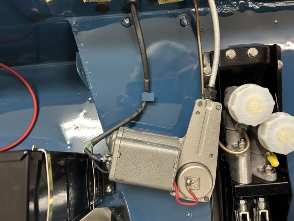
The wiper motor, as taken from the car, turned out to be pretty dirty and it did not operate.

Wiper Motor

Rotating Arm & Gear

Time for a clean-up

It appears to be the original motor as the casing has a stamped production date of 12/1958, so just before the car came off the assembly line. We disassembled the motor, gave it a good cleaning, lubricating and painting and after hooking it up to a power source we judged it to be operational and good for continued use in the Bugeye!

Video Episode Forty-one details the motor refurbishment process:

https://vimeo.com/822229818/8c4114ef7f?share=copy

The motor is only one speed – slow. The same wiper motor was used in the Big Healey and we decided to add the same intermittent speed controller that my Dad incorporated in  the 3000. It doesn’t make the motor any faster, but it does greatly improve the operation of the wipers in misty conditions.

Intermittent Wiper Control

Ed Esslinger authored an article on a Sunbeam Tiger web site about a kit he put together to provide unlimited variable control of the speed of the Lucas wiper motor. We will probably install the control knob for the variable speed rheostat on the vertical panel that will be created later to fit between the dash and the gearbox tunnel.  The controller electronics will be hid behind the panel. The kit can even be wired to accommodate most state laws that now require your lights to be on when the wipers are functioning! The lights come on automatically. This is the instruction sheet: Wiper Control and a wiring diagram:

Wiper Control Diagram

Wiper Control Diagram

Intermittent Wiper Kit

Intermittent Wiper Kit

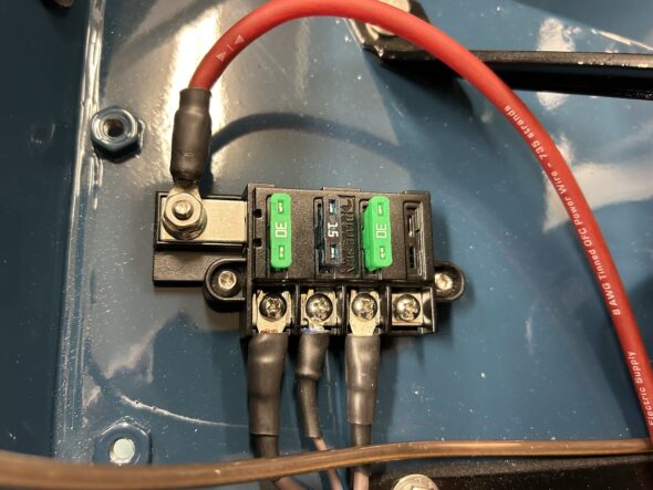
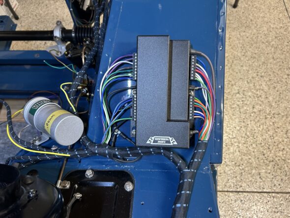
The following image illustrates the actual wiring in the Bugeye using the Classic Technologies Relay/Fuse Box:


Exterior Lighting

This post covers the restoration and/or replacement of the lighting fixtures of the Bugeye Sprite. The image below taken from the Sprite Service Parts List illustrates the components of the car’s lighting system:

Bugeye Lighting

The Bugeye Restoration Video Episode Forty (link below) covers our restoration efforts. Where parts were perished, such as rubber seals, they were replaced with new items. However, some original parts were cleaned and repainted to continue their service.

Headlight bowl and mounting ring

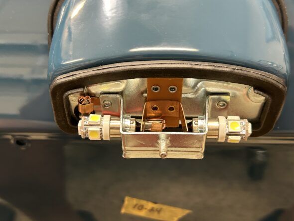
Light bulbs in the flashers (turn signals) were replaced with LED units. These are much brighter, consume lower amperage, and produce less heat. This requires replacing the flasher relay can with a substitute suited for LEDs. The headlights currently on the car are Wagner sealed beam halogen bulbs and we will continue to use these. The bulbs in the number plate lamp are incandescent units and we will also continue to use these.

The headlight chrome rims are secured to the headlight bowl with a clip and screw as seen below:

Headlight Trim ring securing screw clip

These screws can be a challenge to mount. MGBs used a spring clip instead of the screw clip. We substituted these spring tension clips and hopefully they will work well. We can always go back to the original approach.

With all of the parts refurbished and accumulated we are now ready for installation at a later date.

Restoration Video Episode Forty:

https://vimeo.com/821030670/8c6841c388?share=copy

Episode Forty includes the following content:

0:00 – Headlight assembly

2:50 – Front sidelights/flashers

3:04 – Rear flashers

3:13 – Number plate lamp

3:31 – Rear tail lights

3:46 – New rubber seals, headlight pigtails, plinth seal, dust seals, spire nuts

5:20 – Trim ring spring clips

Bonnet Wiring Harness and Lights Removal

My car has been modified to convert the bonnet from the original hinge at the rear, opening from the front, to a front hinge opening at the rear. This is a common modification and it does offer much greater and easier access to the engine and other under-bonnet components. I want to be able to quickly and completely remove the bonnet from the car if the need arises and this means that the wiring harness that services the electrical needs of the front of the car must provide for an electrical connector joining the primary system to the bonnet.

The bonnet includes the LH and RH combined side and flasher lights, the LH and RH main beam headlight, and the LH and RH high beam headlight. 

Video Episode Thirty-nine details the removal of the wiring harness and the lights:

https://vimeo.com/817788749/594dff6323

Episode Thirty-nine includes the following content:

0:00 – Removing the bonnet electrics

0:40 – Wiring harness splice with connector

0:50 – Harness routing in the bonnet

1:27 – RH sidelight/flasher removal

2:00 – Headlight components and trim ring fixing

3:00 – Headlight plug to bulb

3:37 – Headlight bucket and seal removal

3:59 – Headlight alignment adjusters

4:58 – Harness routing

5:07 – LH side light and flasher

5:32 – Wiring harness removed


Electrical System Deconstruction

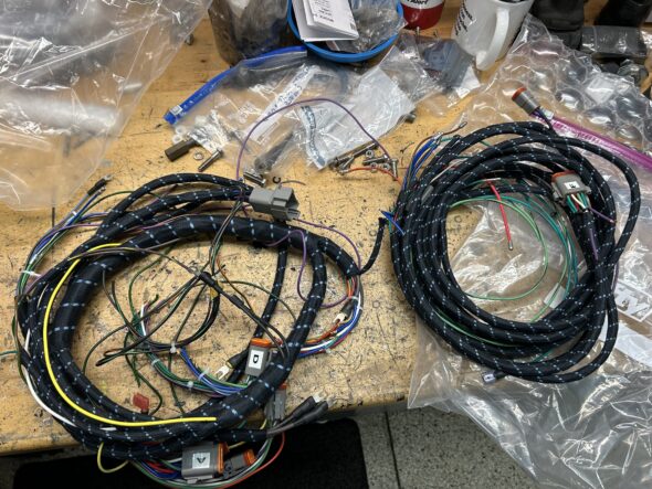
We will be completely replacing the wiring in the Bugeye with new materials including a new relay/fuse panel sourced from Classic Technologies. Before we can give attention to the “new” going in, the “old” must come out. Just to help with resolving any wiring issues later, we will be disciplined in the removal with video and written documentation of how things are installed. What is coming out of the car is not original, in fact, it is not even a professionally produced harness. The previous owner built his own harness which while not very elegant did seem to function effectively.

There is quite a lot of work involved in removing and documenting and the process took several days. The links for a three-part video series are provided below along with a sequential index of video content for each.

Bugeye Restoration Video Episode Thirty-six may be found here: https://vimeo.com/814019363/4c3a30ee20

Episode Thirty-six includes the following content:

0:00 – Heater blower switch

1:29 – Windscreen washer

2:12 – Dash Steady bracket

2:40 – Wiper switch

2:52 – Wiper motor

2:56 – Rheostat knob for tachometer and speedometer lamps

3:04 – LH forward kick panel removal

4:30 – Dipper switch

4:57 – Panel lamp switch

5:10 – Flasher warning lamp

5:40 – Tach wiring to ignition coil

5:50 – Radiator fan toggle switch

5:57 – Ignition/Lighting switch

6:27 – Start pull knob to solenoid

6:42 – Choke cable

7:05 – Water tem/oil pressure gauge

7:35 – Water temp gauge capillary tube

8:28 – Horn push button wire

9:24 – Starter cable and grab handle

9:45 – Choke cable removal

9:49 – Steering column dash collar removal

10:19 – Bare dash fascia

Bugeye Restoration Video Episode Thirty-seven may be found here:

https://vimeo.com/814045832/a23ed5228f

Episode Thirty-seven includes the following content:

0:00 – Wiring harness to dipper switch

1:18 – Ignition/Lighting Switch red wiring to front, rear and panel lights

1:46 – Wiring harness to the rear of the car

2:18 – Dipper switch wiring connections

2:26 – Wiper Switch

3:34 – Speedometer high beam warning lamp

5:00 – Gauge lamps ground wires

5:10 – High beams headlight wires

5:42 – Ground wire for gauges and front lights

6:57 – Windscreen washer wiring assembly

7:08 – Modification of dipper switch bracket

8:25 – Panel lamp switch wiring

10:20 – “A” terminal of Ignition/Lighting switch wiring to starter solenoid and fuse panel

Bugeye Restoration Video Episode Thirty-eight may be found here:

https://vimeo.com/814076642/7844f4f2b5

Episode Thirty-eight includes the following content:

0:00 – Boot side panel removal

0:19 – Electrical fixtures at the rear of the car

0:42 – RH tail light

1:20 – RH tail light wires

1:40 – LH tail light wires

1:50 – Flasher lights

2:39 – Number plate light

3:10 – Number plate plinth and light

3:40 – Number plate light wiring

4:25 – Wiring harness to the rear of the car

5:45 – Fuel gauge wiring

6:42 – Flasher warning indicator

7:00 – Flasher canister

7:18 – Flasher audible alarm wiring

8:20 – Flasher switch

8:42 – Flasher canister wiring (again)

9:28 – Horn relay

9:58 – Coil wiring

10:08 – Alternator wiring

10:50 -Battery cable to starter solenoid

11:02 – Wiper motor wire


Front Suspension, Brakes and Steering Completed

It has been a little more than three months since we began the work on the front suspension, brakes and steering in the Bugeye, but we have now completed the rebuild and have the car back on its tires and on the ground!

Everything has been updated and documented in previous posts in this blog:

New hub bearings and seals

New king pins and bushings in the spindle axles

New rotors, calipers and brake pads, new Goodridge stainless brake hoses, new cunifer hard brake pipes, new “Sebring-type” pedal box and pedal pads with separate master cylinders

New “A” arms, fulcrum pins and poly bushes throughout

New steering rack, shims and rod ends and the proper steering arms were sourced and installed

Rebuilt lever shocks and new rubber bump stops

New coil springs

Everything cleaned and painted

The Bugeye Restoration Episode Thirty-five video shows the final steps in completing the work described above. 

https://vimeo.com/810655660/46123c8339

The following steps are addressed in the video:

0:00 – Torquing the hub nuts and installing split pins

0:44 – Hub grease caps installed

0:48 – Front caliper banjo bolts installed

1:20 – Goodridge Stainless Steel flexible brake hoses installed

1:35 – Making brake pipe bubble flares

4:42 – Master cylinder to brake union brake pipe installed

5:00 – Steering rack installed

5:52 – Steering rack bracket shims installed

6:14 – Steering column to steering rack pinion shaft mating

6:50 – Steering rack mounting clamp bolts torqued

7:17 – Tie rod ends fitted and torqued

7:30 – Toe-in adjustment

7:50 – Front tires mounted and car placed back on the ground

9:12 – Inner fulcrum pins tightened


Rebuilt Front Suspension Installed in the Car

It seems that we have been working on rebuilding and installing the front suspension for a very long time, but in this post the suspension and front brake components are finally reinstalled in the car.

We attached the lower “A” arm to the hub assembly. This involves positioning the king pin between two cork washers and screwing the fulcrum pin into the “A” arm the outer bushing, through the king pin and into the other side of the “A” arm.

Screwing fulcrum pin into “A” arm and king pin

The fulcrum pin needs to be centered in the king pin with the concave curve in the pin open such that the cotter pin (with one flat side) can be inserted into the king pin and pushed through the fulcrum pin so that a nut can be attached to the lower end of the cotter pin. This process is covered in the attached video.

Cotter pin in place

After going through that process we discovered that the steel bushes in the used “A” arms were completely knackered with way too much play and we had to order a new pair. The “a” arms are available from British Heritage and are supposed to be as original, however, they are very expensive. A lower priced aftermarket “A” arm, produced in the UK, is also available and contributors to the on-line Sprite Forum reported that these units are satisfactory. So, we ordered a pair of these from AH Spares and repeated the process of mounting the hub assembly to the “A” arm!

After market “A” arm and new coils spring

One side of the “A” arm outer bushing was already capped, but the other side required a screwed plug and grease zerk to be screwed into place.

“A” arm grease zerk fitting

The next step was to install the hub assembly and “A” arm (wishbone) to the car. While supporting  the weight of the hub assembly on a floor jack, the assembly was secured to the damper arm with the top fulcrum pin.

Supporting hub assembly to insert uppertrunbnion fulcrum pin

Like the lower pin, there is a concave spot on the shaft of the bolt through which the damper pinch bolt must align in order for the pinch bolt to screw into the damper arm. The top fulcrum pin is inserted from the rear through a new rear poly bush, pushed through the upper trunnion, and then through the front poly bushing before passing through the damper arm where it is then secured with a castle nut and split pin.

Upper Trunnion bolt washers and poly bushes

Upper Hub Assembling Mounting


The Upper Trunnion sits atop a thrust washer on the swivel axle. Two small shims are placed on the king pin below the thrust washer and upper trunnion before they are placed on the top of the king pin. After the upper trunnion is in place a nylock nut is used to tighten the swivel axle assembly. At this point we have the hub assembly secured at its top. We did not tighten the upper trunnion until after we mounted the lower “A” arm to the car.

New poly bushes were mounted on either side of the inside of the “A” arm and using a combination of a floor jack and a bottle jack the inside of the “A” arm was pushed into place so the the inner fulcrum pins could be pushed through and secured with nylock nuts. These won’t be tightened until we have the weight of the car on the ground.

With everything mounted properly it was time to tighten nuts and bolts. The top trunnion nut was torqued to 40 ft. lbs. If the rotation of the hub (front to back) is too tight a shim is added, if there is too much play a shim is removed.

We then tightened the two bolts that secure the caliper to the swivel axle. These are tightened to 46 ft. lbs. The tab washers under the bolt heads will be turned up at a later date. The steering arm bolts were torqued to 39 ft. lbs. The tab washers under the bolt heads will be turned up at a later date. Finally, the three mounting bolts on each damper were torqued to 27 ft. lbs.

Everything buttoned up

The next step was to install the front coil springs. The spring seats, or pans, were removed  from the “A” arm. The spring was then placed on the spring seat and pushed upward through the “A” arm wishbone. Compressed springs can be very dangerous and consequently we choose to use long threaded rods to safely compress the springs.

We prepared four 5/16″ – 18 “all-thread” rods by cutting each to six inch lengths. Double nuts were placed on the top of the rods and tightened against one another. Coupling nuts were used on the top and bottom to make the nuts more accessible to turn with a wrench. Flat washers were also used between the spring seat and the nuts.

The nuts were gradually tightened until the spring was compressed and the spring seat was tight against the “A” arm. Then, one at a time, the long rods were loosened and replaced with 5/16″-24 x 3/4″ hex head bolts and nylock nuts.

Coil spring installed

1 1/8″ wooden spacer block to simulate normal hub height

We will still need to bend back tab washers, lubricate the grease zerks and tighten the inner “A” arm fulcrum pins, tighten the hub nut and insert its split pin and install the grease caps. But, these are all little steps to be accomplished later. The big stuff is done.

Bugeye Restoration Video Episode Thirty-four addresses the joining of the hub assembly with the lower “A” arm (wishbone) and the the installation of the combined assembly to the car.

https://vimeo.com/807699575/1a3cf45eb0

The following steps are addressed in the video:

0:00 – Lower “A” arm installed to king pin and swivel axle

1:18 – Outer fulcrum pin, cotter pin and grease fitting installed

2:29 – Excessive play discovered in old “A” arms

4:00 – Lower coil spring pans installed in “A”arms

4:30 – Hub assembly and “A” arms installed in car

5:00 – Poly bushes installed in inner “A” arm and then to car

5:53 – Damper pinch bolt and upper fulcrum pin

6:52 – Torqueing the caliper, steering arms, and damper bolts

7:24 – Coil spring installation with “all-thread” rods


Front Brakes, Pedal Box and Steering Rack

Brake Pipes – Sometimes as one proceeds with working on the major systems of the car parts just get in the way! We are installing the modified Sebring-style pedal box with separate Girling master cylinders and that requires bending a new brake pipe with a different configuration from the original. To form the new pipe and trial fit it to the car we found it easier to remove the windscreen washer pump located on the firewall and to loosen the wiper motor mounting as well. “Easier” is a relative term! Not exactly easy to get to the nuts on the inside of the firewall to release the pump.

Easy is a relative term

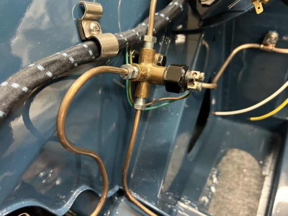
Using the brake pipe supplied in the Bugeye brake pipe kit that has pipe cut to length with fittings installed for the pipe from the master cylinder to the pipe union proved to be a little too short so we have ordered some extra 3/16″ pipe from FedHill. The short pipe was used to go ahead and make the pipe bends that will become a model for the FedHill pipe when it arrives. 

We then went ahead and bent the pipe for the route from the union to the RH front wheel and the pipe from the union to the LH front wheel. The LH pipe runs over the front chassis crossmember and is held in place with two brake clips.

Crossmember brake pipe clips (2)

LH and RH front brake pipes at Union

To make sure that we did not end up with a conflict between the pipe and the steering rack we went ahead and temporarily installed the steering rack. Permanent installation will occur a little later.

At the front of the car the hard pipe attaches to a clip on the chassis where it is joined by a flexible black stainless steel Goodridge hose. The other end of the hose then screws into the brake caliper.

Brake hose to Brake pipe chassis clips

The brake pipe that runs from the union to the back of the car was removed, but we will wait until the engine and transmission are removed from the car to shape and install the pipe. There just isn’t enough room to maneuver to install the new pipe with the engine in the car. All of the original pipe was removed from the car and stored away just in case we need it in the future. The pipe may be ultimately tossed away but we will keep all of the end fittings.

Brake Pads – We had ordered new Gold Cup brake pads from Moss Motors only to discover that they were just slightly too thick, preventing a good fit in the new calipers. We ordered a set of EBC pads and like Cinderella, found that they were just right. These were installed with new spring retainers and split pins. We won’t bend the pins back yet.

EBC Brake Pads

New calipers, EBC brake pads, Retaining Springs and Pins

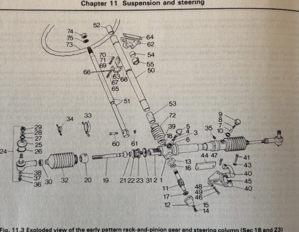
Installing the new steering rack acquired from AH Spares proved to be a simple job. The lower brackets were installed on the car with the three 5/16″ – 24 x 3/4″ bolts for each bracket. We have new shims to install in the cradle of the brackets but we aren’t going to install them now. We will wait to use the shims when the final installation on the car is accomplished after paint. After the brackets are mounted to the chassis, the rack can be lifted into place and the top brackets can be screwed into place. We left everything loose until the steering column and the steering rack were mated and the pinch bolt installed. Then everything was tightened down. The steering rack clamp bolts were torqued to 20 ft lbs. The steering rack mounting bolts were torqued to 17 ft. lbs. The steering column pinch bolt was torqued to 10 ft. lbs.

The Sebring-style pedal box was reinstalled with its proper foam gasket. The gasket doesn’t align perfectly and required some manipulation. We decided to glue the gasket/seal to the pedal box but used no adhesive between the seal and the car. Ten 1/4″ – 28 x 5/8″ stainless steel hex bolts and flat washers are used to secure the box to the car. 

Because the Sprite was manufactured to be set up as either a LH or RH drive, there is an opening in the chassis sub-structure for a pedal box on the RH side of the car. We fit a new pedal box blanking plate and gasket to this location to make sure everything fit but then removed them so they would not be damaged. The blanking plate uses only eight 1/4″ – 28 x 5/8″ bolts. We will install again after paint. While cleaning the area for the new blanking plate we discovered the original Cherry Red paint used on the car. Just a fun fact.

Original paint discovered

Blanking Plate Installed

The rebuilt front dampers were bolted in place in preparation for the installation of the front suspension. Each damper is secured with three 3/8″ – 24 bolts into captive nuts in the chassis.

Our next step will be to install the refurbished/new front suspension and brakes.

The Episode Thirty-three video includes the windscreen washer pump removal and the beginning of the brake pipe replacement with new conifer hard pipe. The rebuilt front dampers are installed along with the black Goodridge stainless steel brake hoses that connect the brake pipes to the calipers.The steering rack is temporarily installed and the EBC “green stuff” brake pads are installed in the front calipers. The steering rack is connected to the steering wheel shaft. The pedal box with its insulation seal are installed as is the new blanking plate and seal for the RH drive pedal box hole. The car’s original paint color is discovered.

https://vimeo.com/806845330/73e781c99d

The following steps are addressed in the video:

0:00 – Windscreen washer pump removal

0:20 – New brake pipe from the master cylinder to the brake pipe union

0:57 – New brake pipe from the pipe union to the front caliper

1:10 – RH front damper installed

2:18 – Goodridge stainless steel flexible brake hose installed from the hard pipe to the caliper

2:30 – LH front damper installed

2:45 – Brake pipe installed from the union to the LH front caliper

4:05 – Temporary installation of the steering rack

4:30 – Brake pipe from union to the rear axle

4:45 – Rear brake pipe connection to the flexible hose and routing under the car

6:10 – EBC front caliper brake pads installed

7:35 – Steering rack connection to the steering column

8:30 – Pedal box and seal/gasket install

10:45 – Pedal box blanking plate installation

11:00 – Original Cherry Red paint discovery