Chapter 31 – Cleaning and Trial Fitting

October 1, 2006

Jeremy Turner’s Work Continues

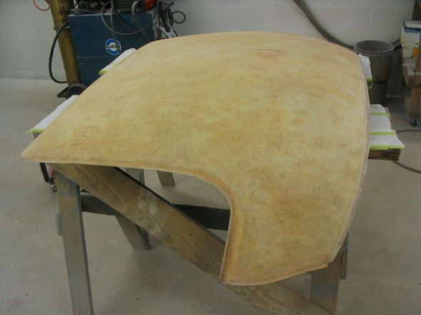
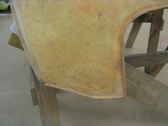
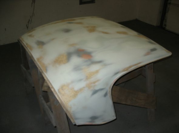
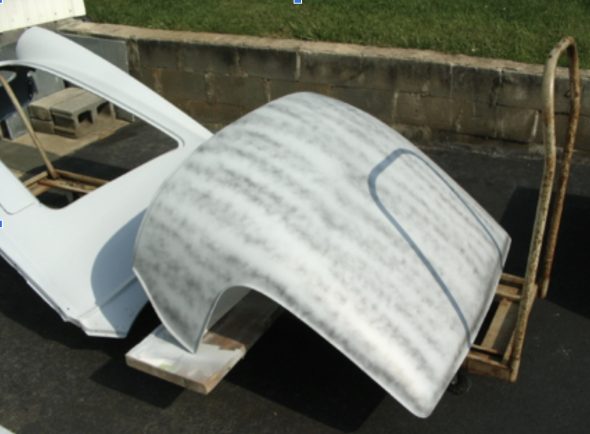
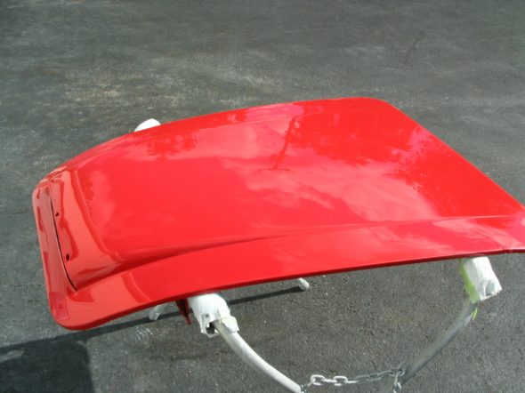
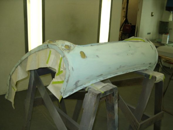
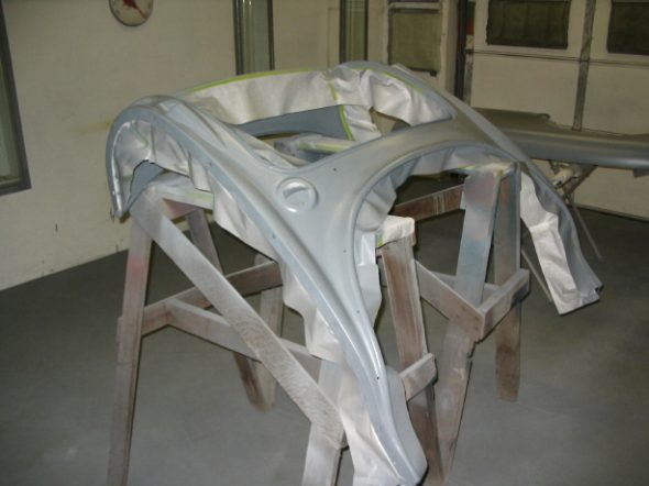
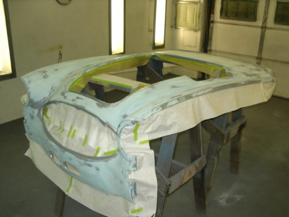
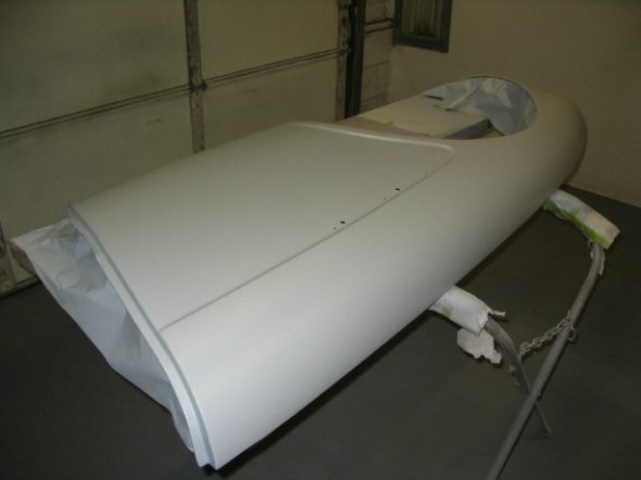
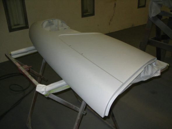
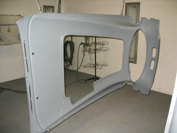
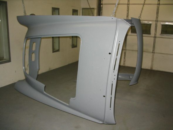
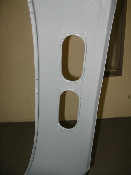
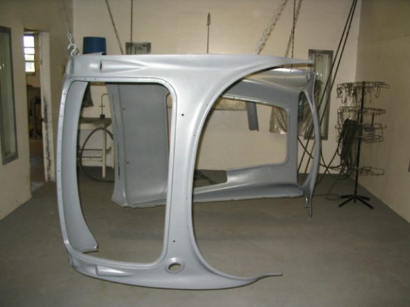
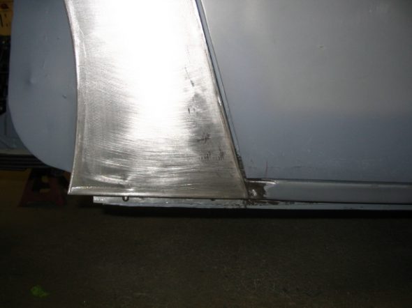
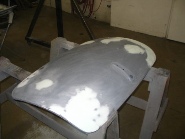
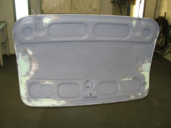
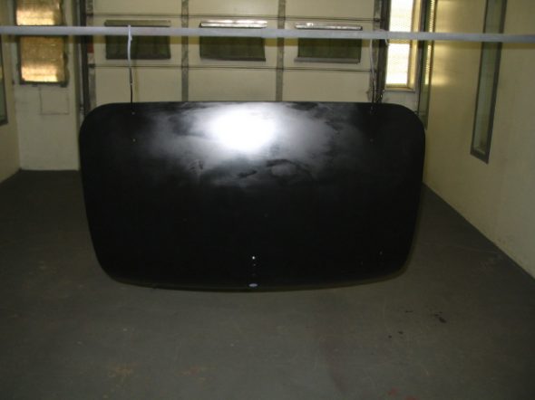
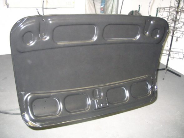
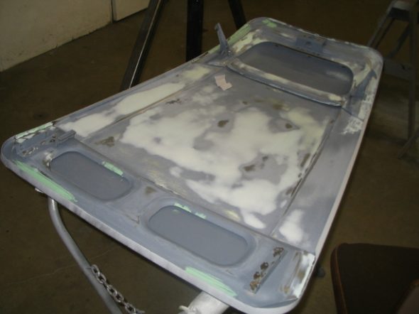
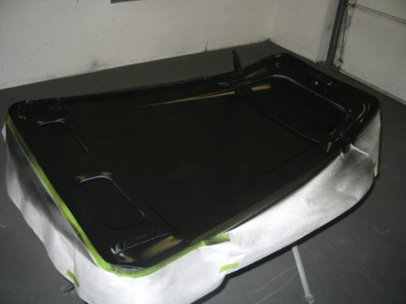
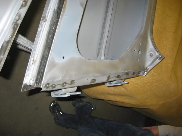
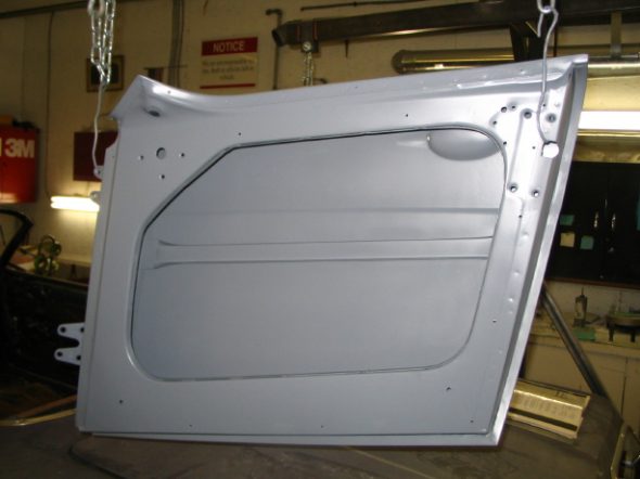
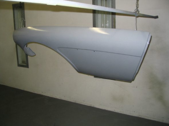
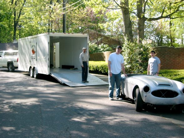
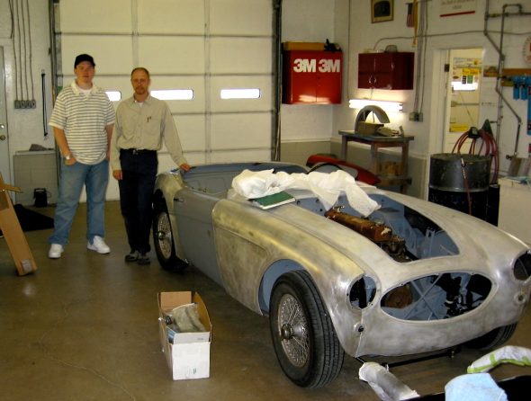
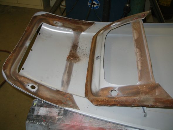
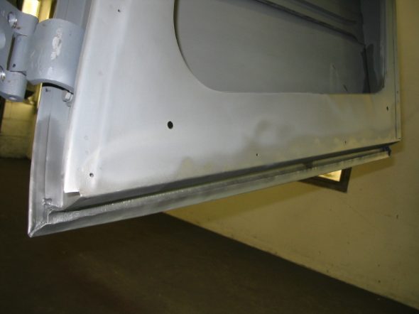
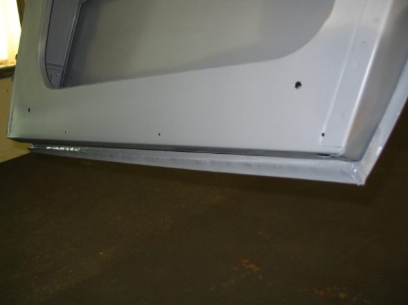
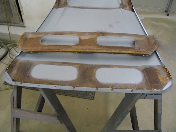
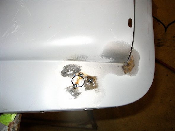
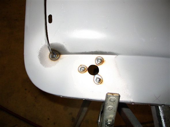
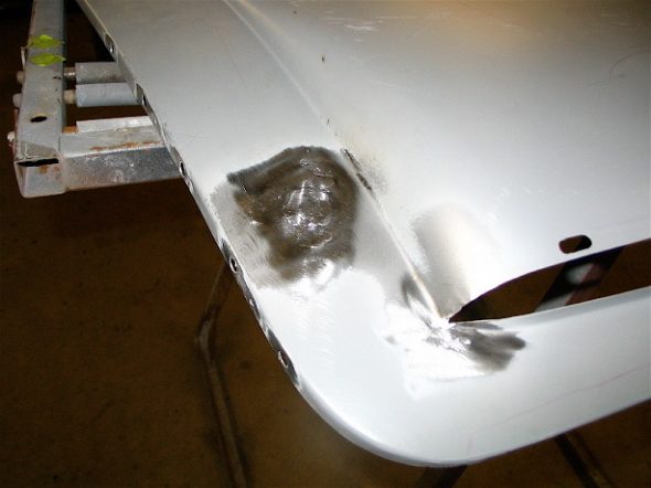
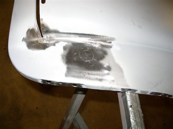
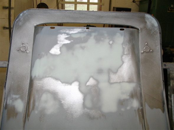
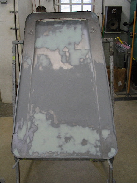
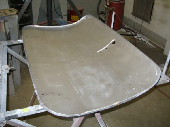
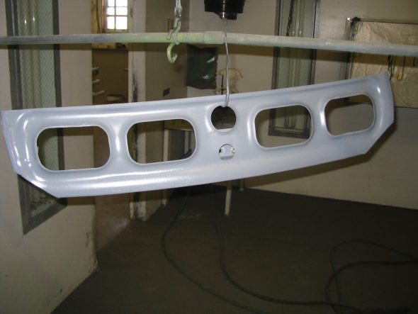
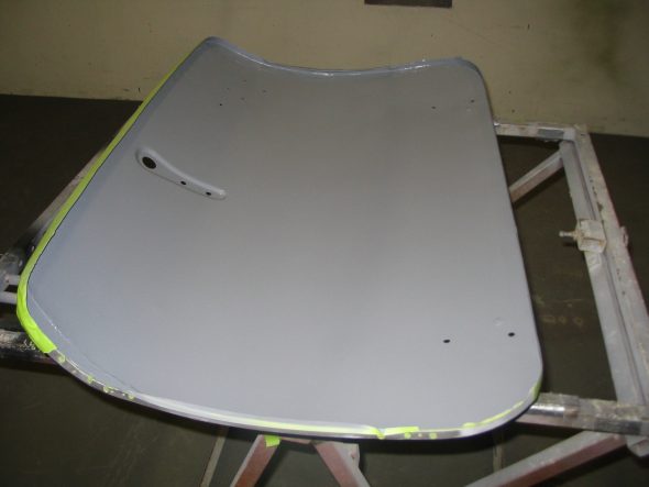
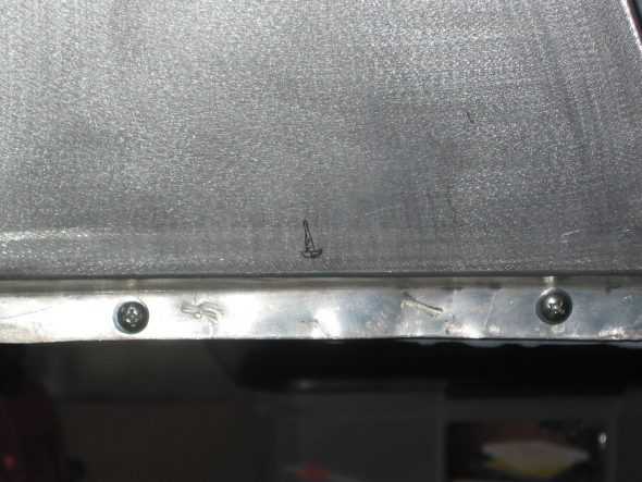
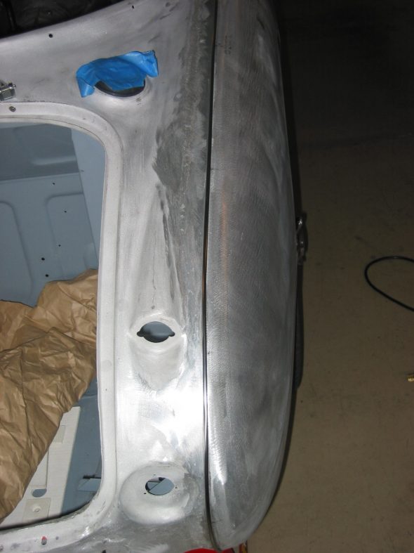
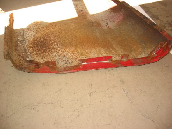
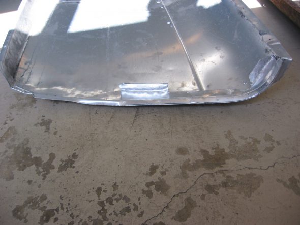
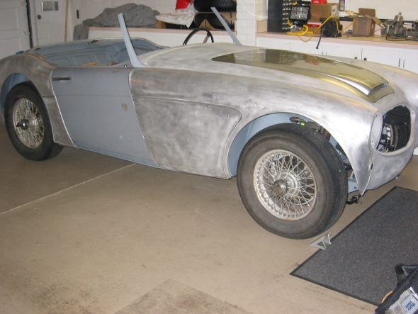
Hardtop – Jeremy packed up the car and got everything in his trailer to bring back to me. We were delayed a day because of rain, so in the meantime he began bodywork on the hardtop. Then it was final priming for the body panels.

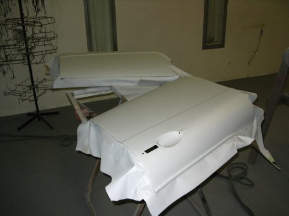
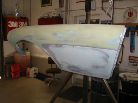
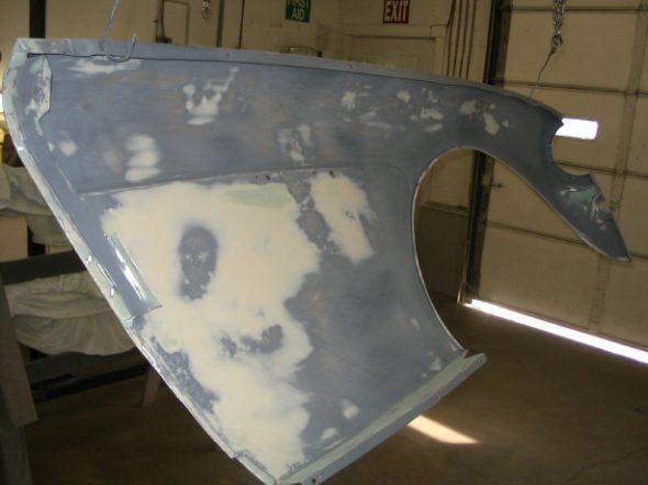
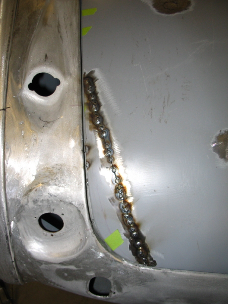
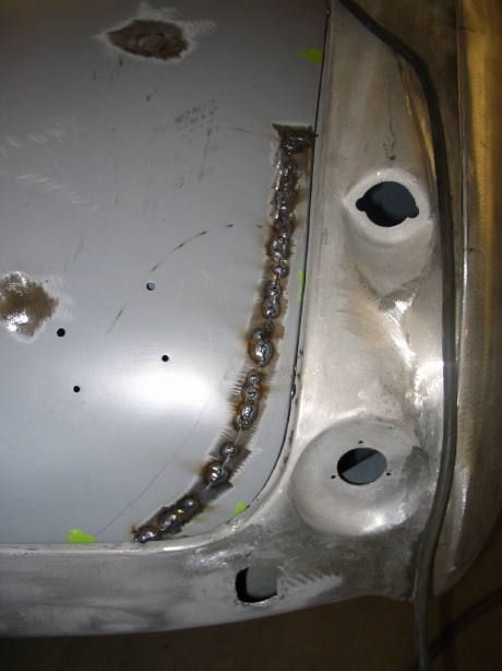
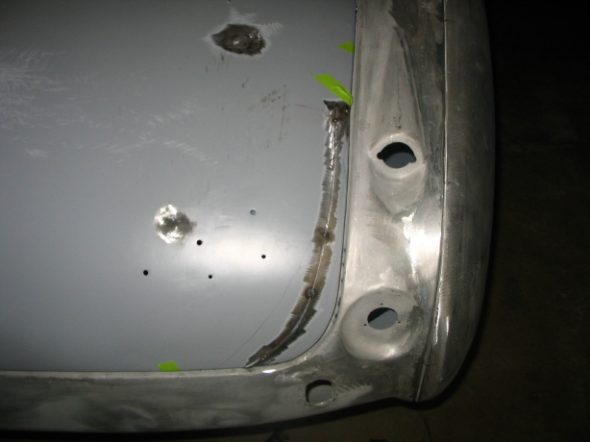
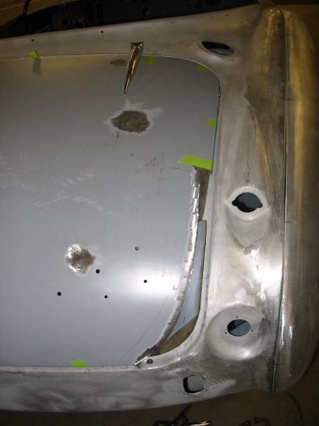
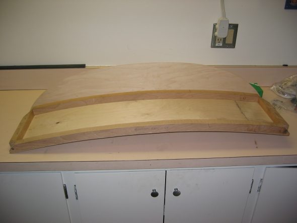
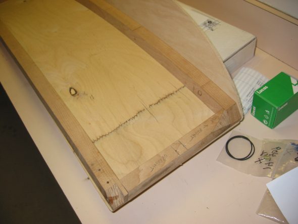
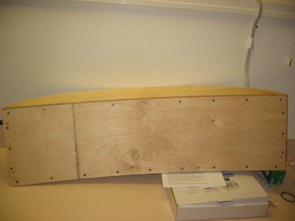
Hardtop 1

Hardtop 4

Hardtop with Filler

Hardtop Prep

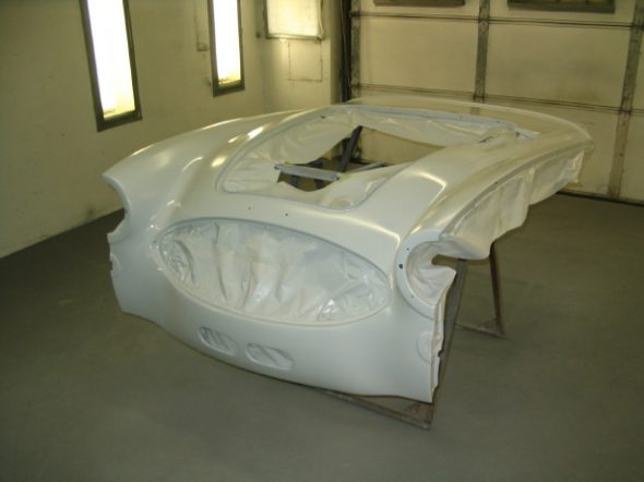
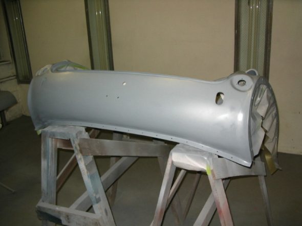
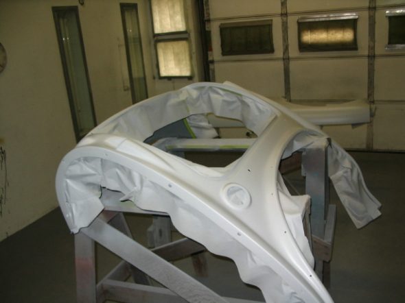
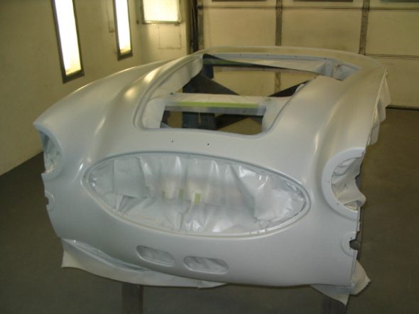
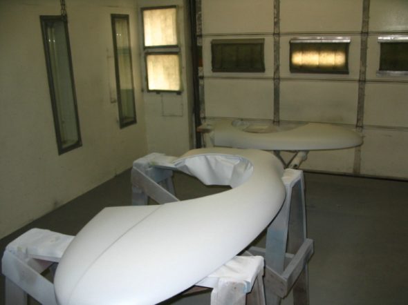
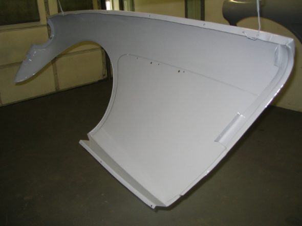
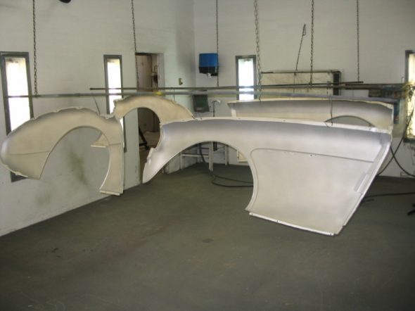
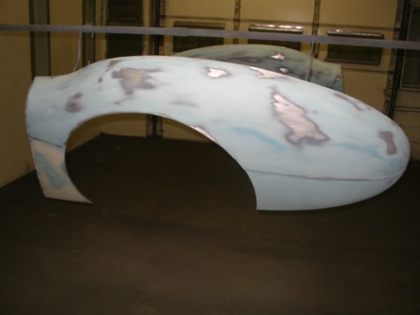
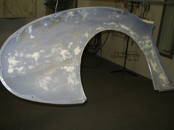
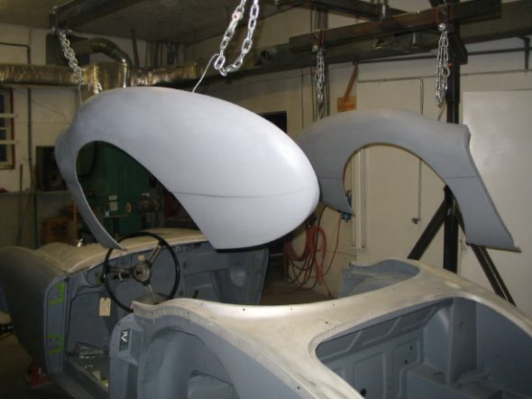
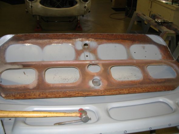
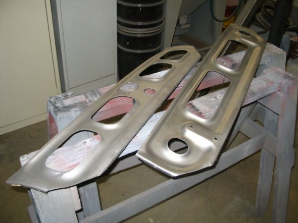
final primed front shroud

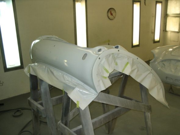
final primed rear shroud

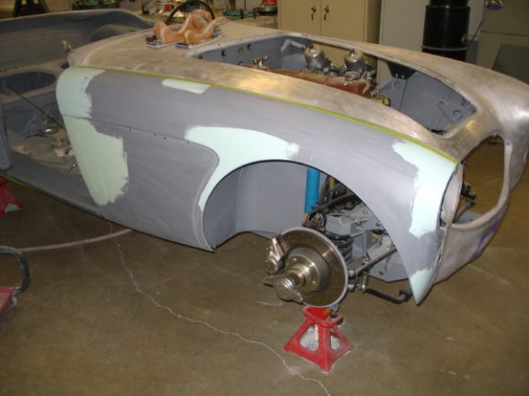
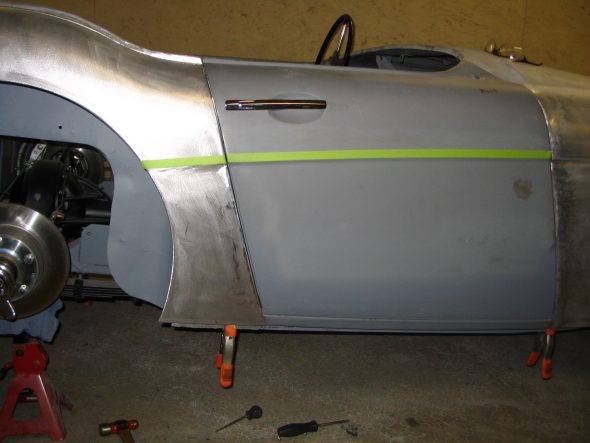
Frame disassembly – With all the exterior panel fitting and bodywork complete, I now have the car to disassemble. I need to remove the engine, and suspension components and put the car on the rolling cart I made. Jeremy will then complete bodywork on the frame and we will be ready to paint.

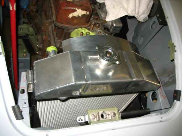
Before I can begin the disassembly there are a few things to be done. First, is finalizing the throttle cable set-up. I also want to check the aluminum radiator baffles that Schickel’s fabricated to see if they are going to fit properly.

October 12, 2006

Work Continues in the Rose Garage

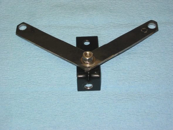
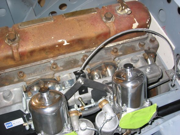
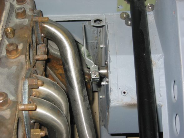
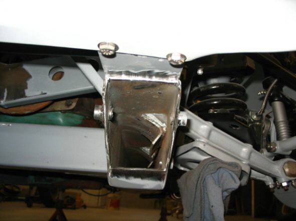
I completed the development of the throttle cable components and fit them to the carbs and the body firewall. This required fabricating a couple of brackets – one at the carbs and one for the firewall. Per Jack Brashear’s instructions, I also modified a stock BJ8 accelerator lever to make it longer (5 1/8”). I used a stainless steel braided cable from Lokar.

Fuel throttle bracket 3

Fuel throttle bracket 2

Fuel trottle lever modified 2

I also purchased some cheap flexible 2” exhaust pipe and cut it to fit so that I knew the lengths needed to order the stainless steel flexible pipe from Epiflex. Being considerably more expensive, I didn’t want to “learn” on the Epiflex pipes!

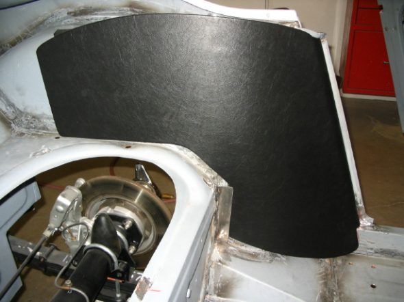
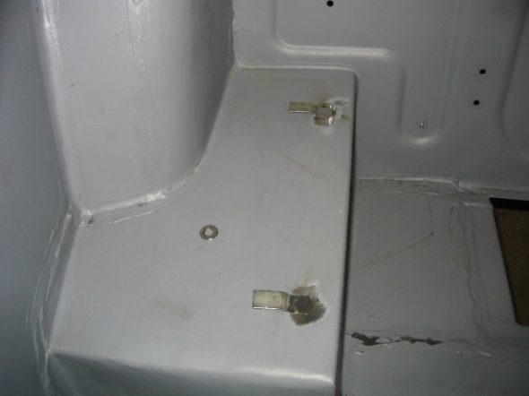
My next job was to install the brackets for the rear seat squab. I installed the rear quarter panels, the rear seats and the squab to make sure the assembly would fit properly on final assembly.

Then removing everything from the superstructure was in order so that I could return it to Jeremy for media blasting, a little body work, priming and painting. After four long years, the next time I see the superstructure it will be RED! One added complication and expense is that I have changed my mind and will use gloss rather than a matte black finish on those components that should be painted black. Therefore, larger pieces such as the axle and the steering box will need to be resprayed. Everything was stripped by October 12 and Jeremy again picked up the car. I then separated all smaller compenents into those items to be sprayed gloss black, red, or engine green and prepared them for delivery to Jeremy. Now I await the return of the red frame and superstructure.

October 22, 2006

A Jeremy Turner Update

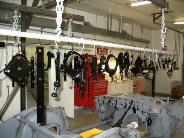
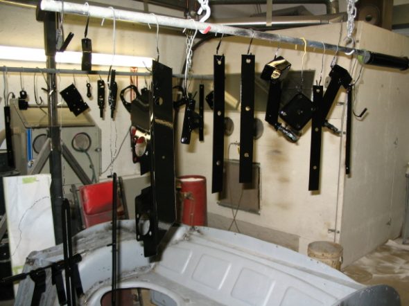
Jeremy took some time from the worst task in the painting preparation process: sanding, and blasted and painted the bits I gave him to be painted black.

Black Painted Parts

More Black Painted Parts

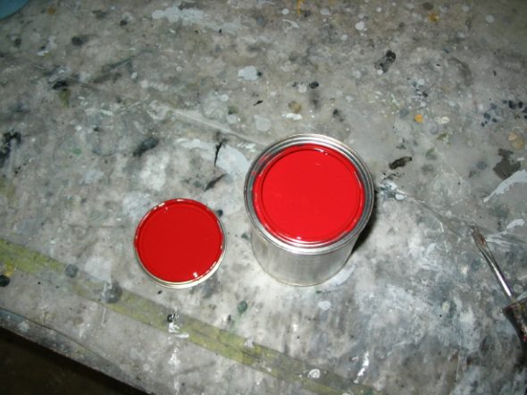
While I remained positive about my choice of exterior paint, we decided to paint a sample just to see what the final color would turn out to be. Jeremy orderd a pint to try.  Judging from the open can it will be a very red car! I love it, but it will be good to see it on a bonnet to get a perspective on a larger sample than a paint can top.

Corsa Rossa ferrari red paint

October 22, 2006

Engine Work Begins

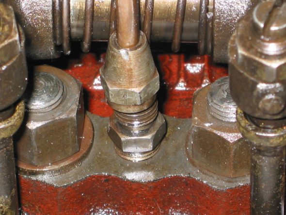
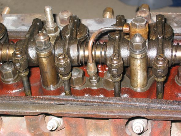
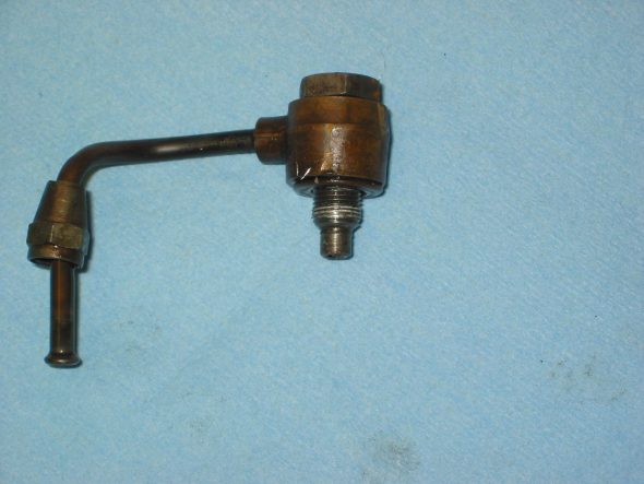
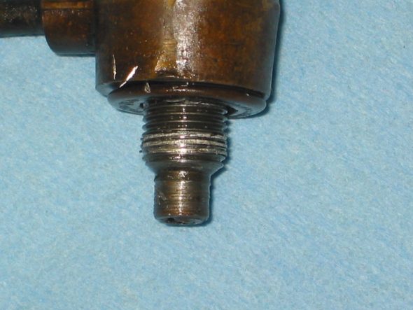
Rocker Assembly – I plan to send the rocker assembly to Rocker Arm Specialists to have it rebushed, so I removed it for cleaning and mailing. First step was to lossen the fitting of the oil feed pipe to the head. Then removed the 12 nuts securing the assembly to the head. When replacing the assembly one MUST fit the oil feed pipe banjo bolt to the assembly BEFORE fastening the assembly to the head! This had apparently not been done previously which resulted in the stripping of the aluminum pedestal. I ordered a new pedestal.

Rocker oil feed 1

Rocker oil feed 2

Rocker oil feed 3_2

Rocker oil feed 4

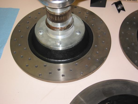
Brake Discs – To prevent rust on the brake rotors I painted the centers of the front and rear rotors.

Brake disc paint

October 26, 2006

Back to Jeremy’s

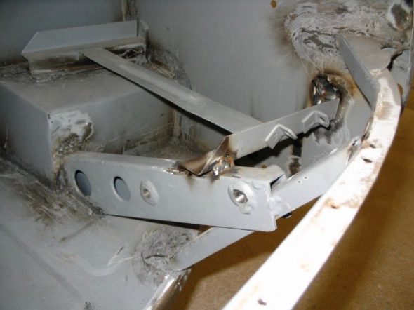
The battery tray   as assembled by Martin did not have enough support at the rear brace, so Jeremy did a little modification so that it would have a solid mount.

battery tray brace

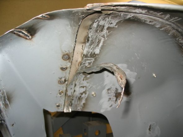
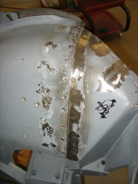
Martin had stitch welded the two pieces of the front inner fenders, and it wasn’t a pretty site. Jeremy took the pieces apart. Cut out some unneeded metal and welded the pieces back creating a much neater appearance.

Inner Fender Repair

Left inner fender repair

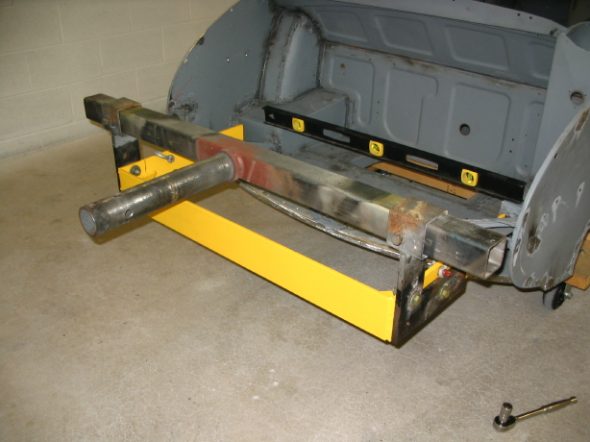
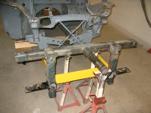
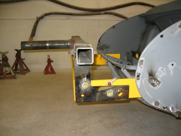
The Rotisseri – I had the yellow brackets in the photos made to fit Jeremy’s rotisseri. This week he got the two together and got the superstructure on the rotisseri. It turns quite easily.

Rotisseri 1

Rotisseri 2

Rotisseri 3

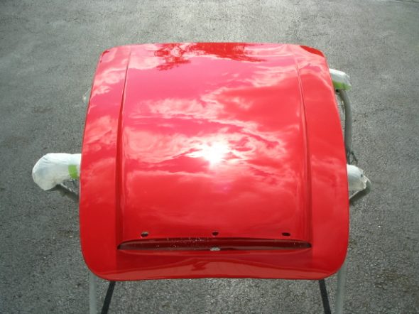
Painting – We ordered a pint of the Rosso Corsa Red paint to try a test panel. We painted the extra bonnet I had. It is beautiful! No modifications to paint formula required. It is definitely a Ferrari Red.

Ferrari Red 1

Ferrari Red 2

Seam Sealer – I spent a half day at Jeremy’s stripping out the seam sealer Martin had applied to the bottom of the car. The rotisseri made the job fairly easy, but it is a dirty, smelly job. Jeremy will now do a little more welding to fix a few places and then he will be ready to glass bead blast the assembly, do some body work to cover old pitting, and prime and paint.


Chapter 30 – Cleaning and Trial Fitting

Jeremy Turner’s Work Continues

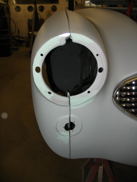
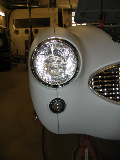
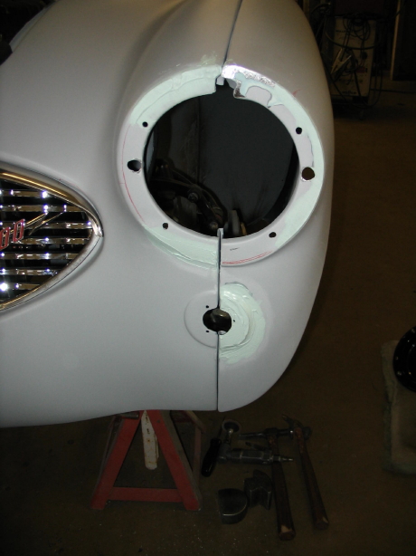
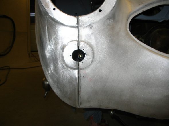
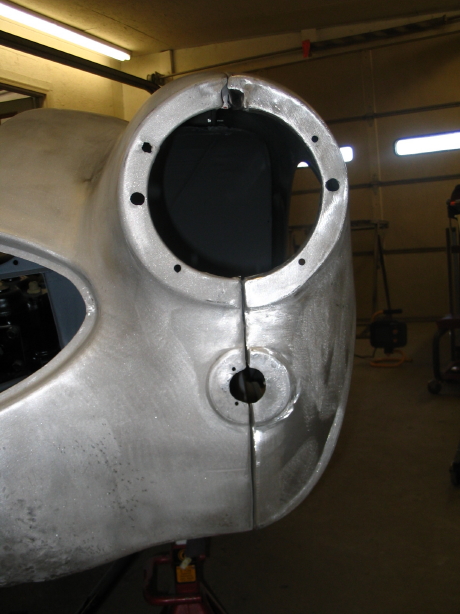
Headlights and turn signals – Jeremy worked on fitting the headlights and turn signal lights to the front wings/shroud. We discovered that the aluminum wings were not molded properly to fit to the shroud. Some body work is required. The result won’t be perfect, but should only be noticeable to Jeremy, me and someone like Rich Chrysler!

Right headlight mounting 2

Right Headlight mounting 

Left headlight mounting 1

Left headlight mounting 2

Fender BeadingThen it was nice to try the fender beads on both front fenders.

Fender Beading

Front Fender Beading

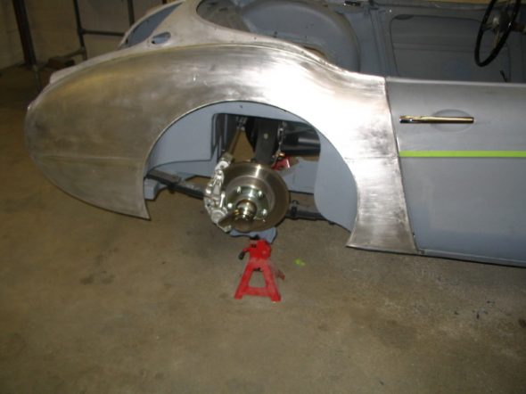
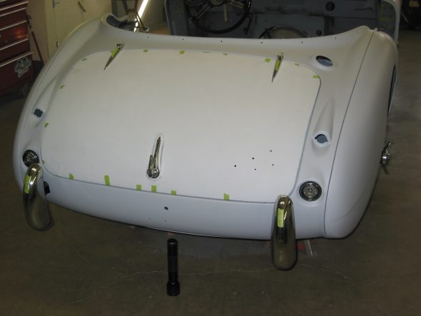
Rear wings and boot lid – Then attention was turned to the back of the car. Rear wings fitted, boot lid tested with the old gasket applied, and the rear rally bumpers fitted as well. Again, great to see continued progress. The goal is to return the car to me in two weeks to be stripped for bodywork, blasting again, and priming of the frame. Getting some red paint on the “Bloody Beast” is nearing!!

Left side in primer

Boot in primer

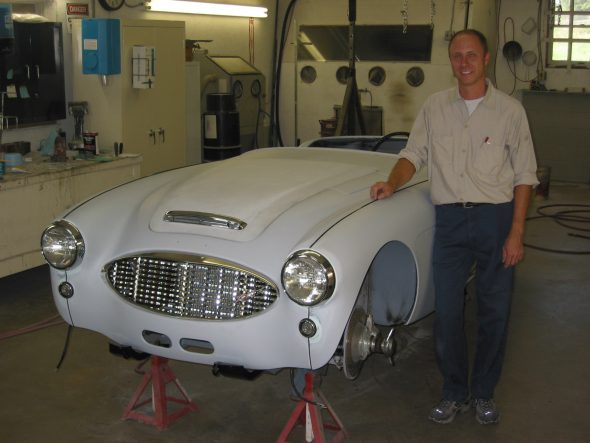
Here is Jeremy Turner, starting to look like a proud father. He just does great work.

Jeremy and the bloody beast

The fender beading is installed in the rear fenders, and the aluminum cowl is put in place.

September 19, 2006

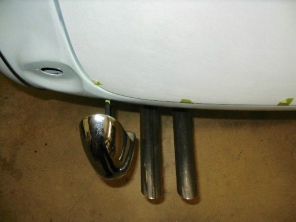
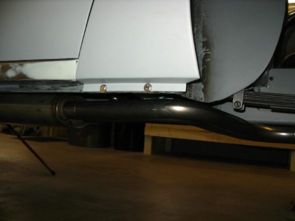
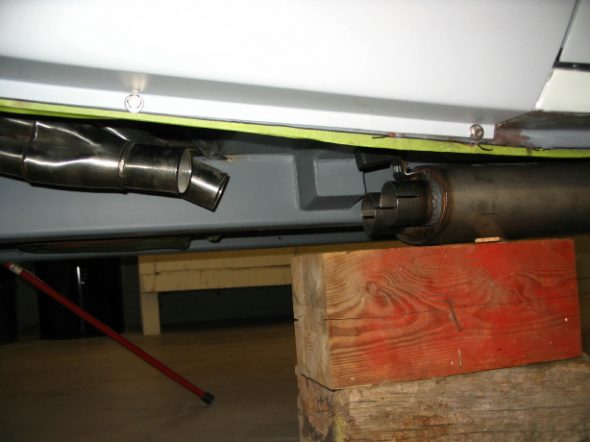
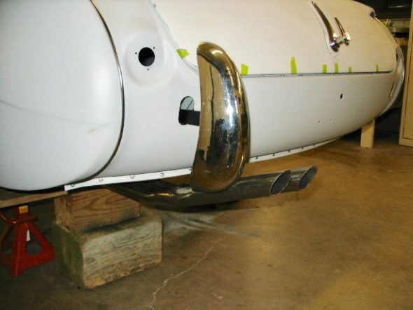
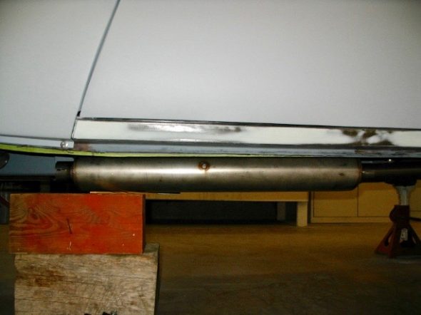
Exhaust – Because the Jule Enterprises frame did not include the mounting points for the exhaust hangers, Jeremy needed to fit the exhaust and determine where the hangers needed to mount to the car.

Exhaust 5

Exhaust 8

Exhaust 3

Exhaust 1

Exhaust 2

Exhaust 4

Windscreen – Yesterday I took the afternoon off and went to Broadway to help Jeremy with a final check of the exhaust system before drilling the holes in the frame and floorboard for the hangers and to install the windscreen. We did adjust the front mount for the muffler to get it up a little higher. The posts for the windscreen did require some grinding to get the windscreen to fit properly, but after several “trial-and-error” fitting sessions, we got the windscreen installed properly. It really made the shell begin to look like a car! I was so excited with the progress I forgot to take photos. I brought a lot of parts home (emblems, lights and etc.) that fortunately are no longer needed for fitting.

 September 22, 2006

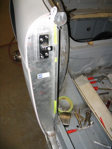
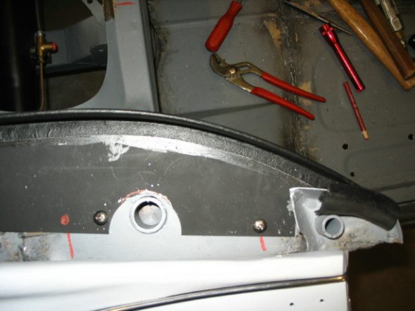
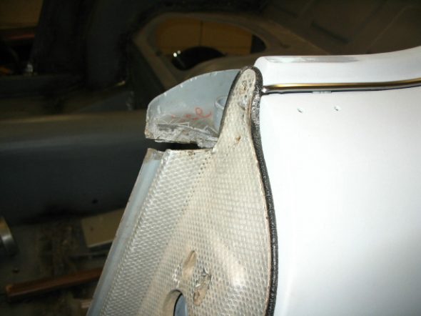
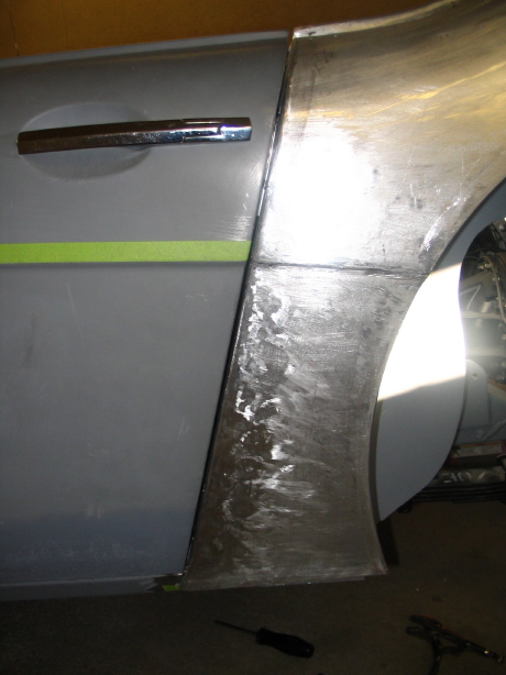
Door shut face finishers again – In order to get the aluminum shut face finishers and the rear quarter panels to fit, we decided that we needed to cut the weld on the front of the hood mount plate and bend it up a bit to have it align with the top of the aluminum trim and to permit the rear quarter panels to slide under. This strategy proved successful, as Jeremy was able to get the new Heritage quarter panels to fit properly. The new shut face finishers from Moss (Kilmartin products) arrived and much to my relief they fit perfectly! The photos also show some small pieces of rubber door seal “Bristle Flex” that came from Macgregor in Canada. It seemed to fit well, although it does not appear as original.

door shut face finisher kilmartin 1

Rear quarte panel fitting 3

The lower bracket that secures the rear quarter panel to the footboard had to be made larger so that it would contain the panel. Jeremy did a nice job of fabricating the brackets. Following complete trial fitting the gap at the front of the hood mount will be welded closed.

Rear quarter panel fitting 2

hood mount reposition 2

 September 27, 2006

Hood Mount Plate – Jeremy welded the front lip of the hood mount plate and completed final fitting of the aluminum door shut finishers along with the vinyl beading. It took some time to get to the point that the door did not rub against the vinyl. 

Anti-sway bar brackets – Then he moved to installing the brackets I purchased from Kilmartin for the anti-sway bar. I still do not understand why Martin Jansen did not install these as part of his Jule frame package.

Sway bar brackets 1

Sway bar brackets 2


Chapter 29 – Cleaning and Trial Fitting

September 4, 2006

Initial Work on the Engine and Driveline

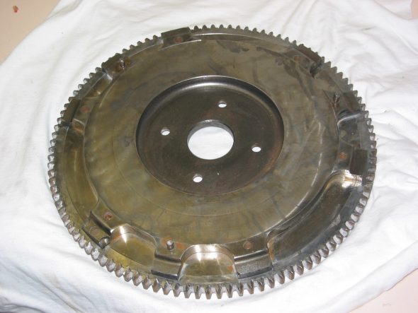
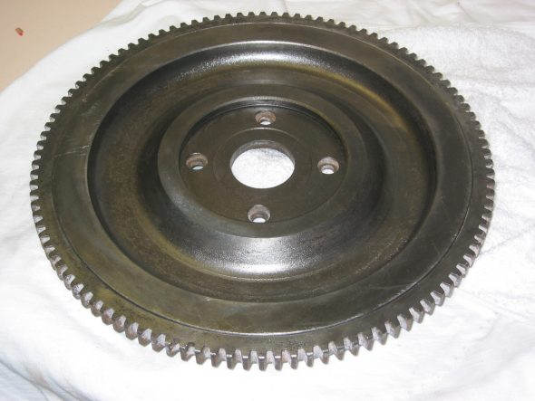
Clutch and Flywheel – Many who have used the Smitty gearbox conversion have suggested fitting a later BJ8 diaphragm clutch rather than the the spring actutated clutch originally used on the BT7. Now seemed to be the time to do it, so I ordered the clutch plate assembly from Moss. I also took the suggestions of others and sent my flywheel to Bill Bolton in exchange for a lightened (now 24 lbs.) BJ8 flywheel. The wheel that came back from Bill was pretty rusty in the non-contact surface area so a little time was spent with rust remover and the drill and wire brush. Even after cleaning, I still think I will give it to Jeremy to media blast the non-contact surfaces.

BJ8 lightened Flywheel 1

BJ8 lightened Flywheel 2

September 6, 2006

Jeremy Turner’s Work Continues

Rear shroud with filler 2

Rear shroud primed 1

Rear shroud primed 2

rear shroud final primer

Shrouds – Jeremy is working on the “Bloody Beast” with the idea of completing all the priming and final panel fitting withn two weeks. He is focused on my car completely. He has just completed the body filler and priming for the front and rear shrouds.

Front shroud bodywork 2

front shroud poly primed

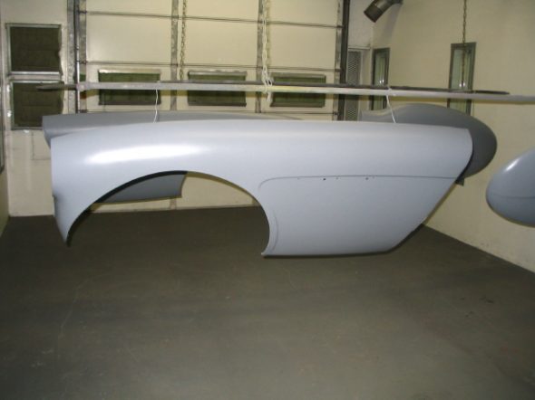
Front wing final primer

right front wing final primer

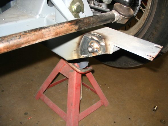
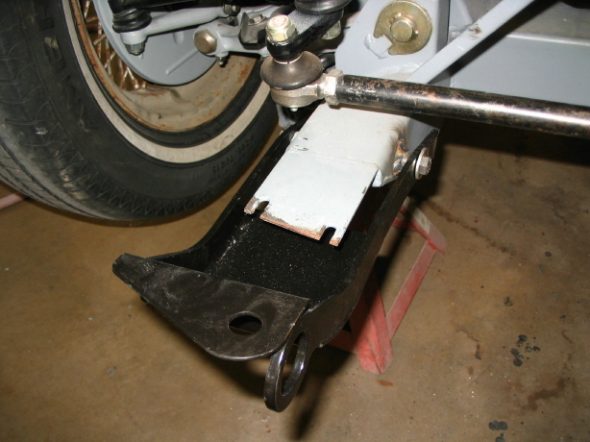
Because Martin Jansen did not put the bumper bracket mounting tubes all the way through the frame, Jeremy needed to weld some short tubing into the inside of the frame rails to mount the Cape International driving light/tow hook.

tow hook mount

tow hook mount 2

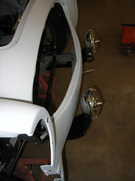
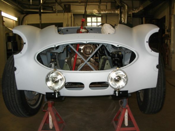
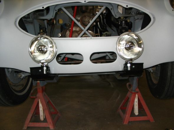
And now, don’t those Lucas drving lights look nice!

Fitting driving lights 2

Fitting driving lights 1

Fitting driving lights 3

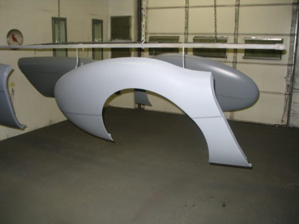
Final priming on doors and rear wings.

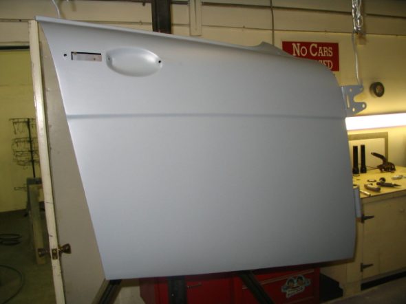
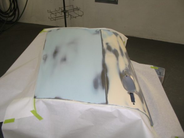
Doors final priming

Rear wings final priming

September 11, 2006

Jeremy Turner’s Work Continues

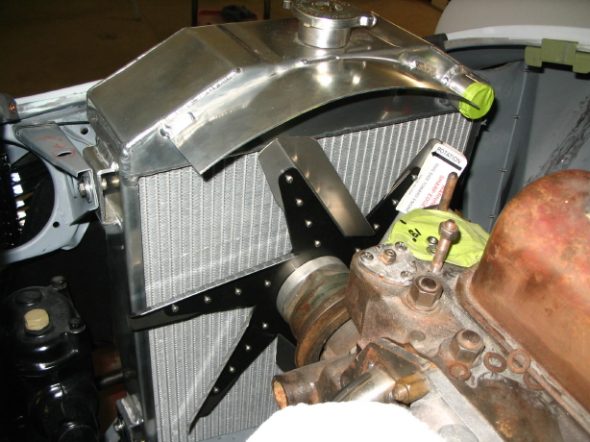
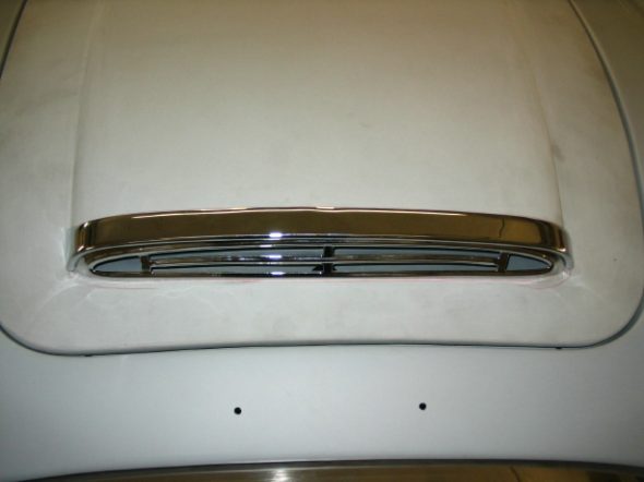
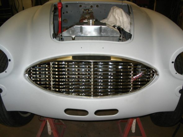
Before going any further, it was a good idea to check the fit of the radiator, fan and the body and bonnet grilles to ensure a good fit. The radiator cap did hit the bonnet so some more work was required to adjust the radiator and shroud. We ended up with about 1/8” clearance between the radiator cap and the bonnet. The bottom trim piece on the body grille wold not fit properly so it was decided to have the original rechromed.

Radiator installed

Fan installed

Bonnet grill installed

Shroud with grille


Chapter 28 – Cleaning and Trial Fitting

March 28, 2006

Jeremy Turner’s Work Continues

front wing body work 5

front wing body work 6

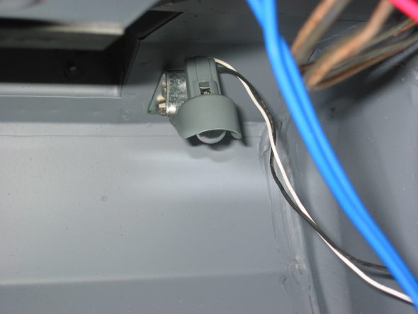
Interior and Boot Courtesy Lighting

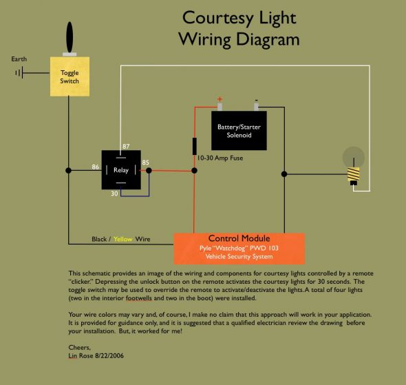
Earlier in the Blog I referenced the installation of courtesy lamps. To avoid switches in the door jams, I purchased a keyless remote. The one I acquired from Pyle was about $40.00. It included two remote “clickers”, the control module, and the wiring. I grossly underutilized all that the Pyle system makes possible, but I was after simplicity. I just cut off all the extra wires, but I can imagine a few other very practical uses. For example, the fuel pump could be wired in and the remote could be used as an anit-theft device by controlling the activation/deactivation of the pump. 

The button on the remote to unlock the car (obviously not needed on a BT7 roadster!) is now pushed to activate the interior/boot lights. As I approach the car at night I can click the remote and my interior and boot lights will come on for about 30-40 seconds and then they extinguish on there own with no other action required. 

I wired in a toggle switch located under the dash (unseen by others) which will overide the remote that I can switch “on” if I want the interior/boot lights to stay on. 

All very simple, clean and unobtrusive. Now if I can just figure out how to disguise that much-to-modern looking remote to look like a british key fob!

Courtesy Light Install

Jeremy Turner’s Work Continues

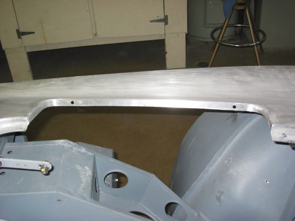
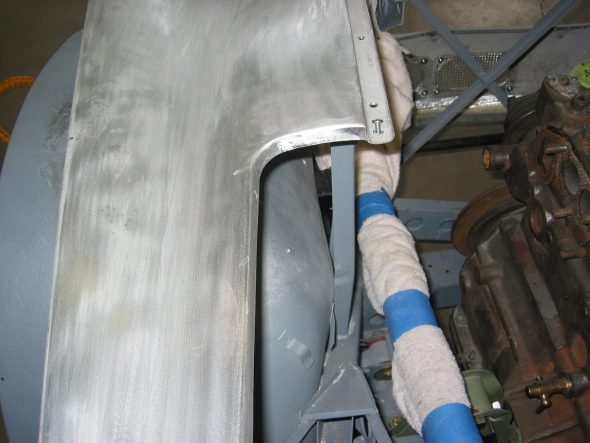
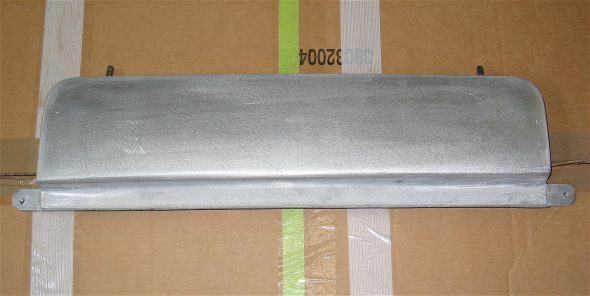
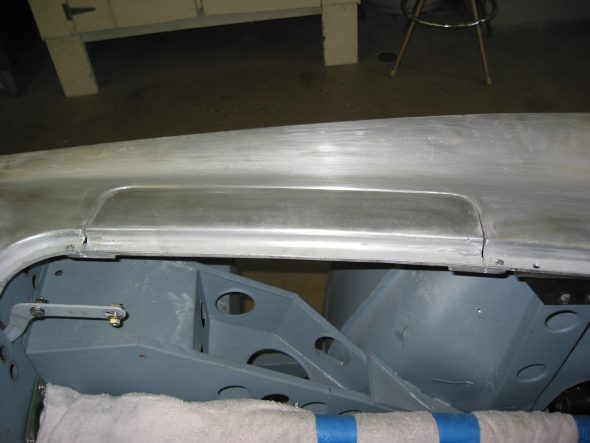
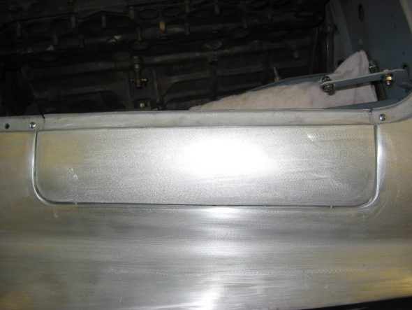
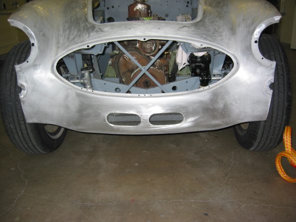
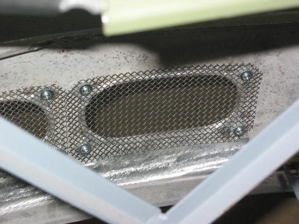
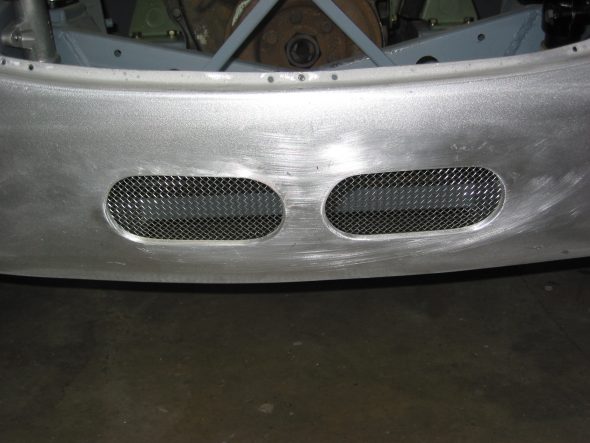
Shroud Modifications – Jeremy called to say that Craig Naff had finished his work and as I had hoped, it was worth the wait! We had asked Craig to cut two oil cooler vents in the the lower valance of the front shroud and to make some repairs in the same area caused by improper towing. In addition, I wanted to create a carb/master cylinder access panel. Unlike the panels you often see on rally cars, I desired something that would appear as original bodywork, fitting flush in the shroud rather than sitting on top. Finally, the rear shroud needed some welding where Martin Jansen has installed new flanges to mount to the rear wings. It turned out the Craig was as good as Jeremy had suggested. I am very pleased with his work.

EDITOR’S UPDATE – April, 2020

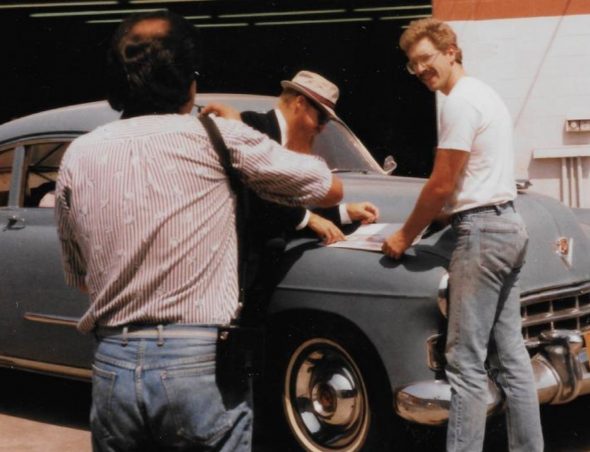
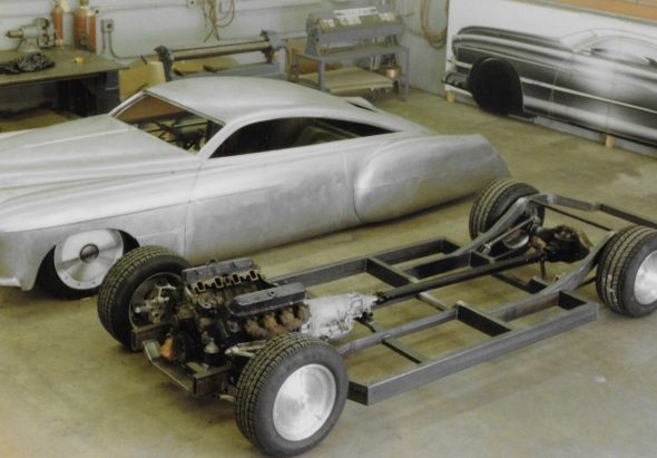
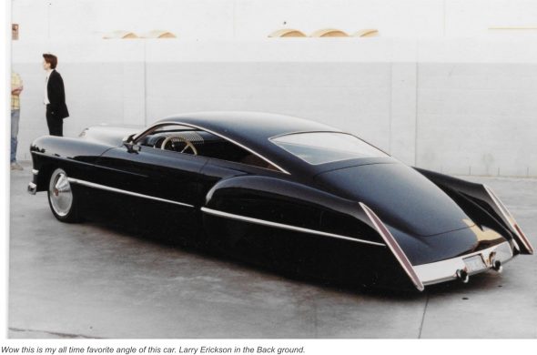
At the time Craig Naff made the modifications to my Healey, I had no idea that he was such an accomplished metal-craftsman with such an impressive portfolio! It is now 2020 and I know that I should have appreciated who was working on my car at the time! Whether he would claim it to be his best work or not I do not know, but his metalwork on Billy Gibbon’s (ZZ Top) 1948 Cadillac is what made him famous. It was about 1989 and Craig was working for Boyd Coddington in California and undertook the job of bringing Larry Erickson’s custom design to life. The world knows the final product as Cadzilla.

Some time later, Craig apparently wasn’t crazy about California life and he returned to his roots in the Valley of Virginia and now has a shop and home outside of Woodstock, VA. Even though I didn’t fully appreciate who Craig was at the time, when Jeremy and I took my Healey to Craig’s shop and I saw the other projects with which he was occupied I did recognize that he was a special talent. Judging by his Facebook Page Craig has stayed busy and is in high demand with a waiting list, but this modest man never boasted about his accomplishments he just turned out outstanding work. Personally, I would consider him to be an artist who happens to work in sheet metal.

Thank you, Craig, for adding your touches to my car!

https://www.caranddriver.com/features/a15132614/the-candy-man/

https://www.customcarchronicle.com/forums/topic/cadzilla-the-craig-naff-files/#.Xpsfzy2ZOd0

Caddy Before Modification with Craig in the White Tee Shirt and Billy Gibbons of ZZ Top in the Hat

Cadzilla before paint

Cadzilla

I concluded some time back that the placement/look of the front vents is all a matter of personal opinion, as long as they accomplish the mission of getting air into the cooler. In my collection of images from cars with vents taken at shows and races, I have seen about as many variaties as there are cars. Craig did hit what I wanted spot-on, so I am pleased. The access panel is, in my opinion, the best arrangement I have seen on any car previously. It will make working on the carbs much easier.

carb access panel 1

carb access panel 2

carb access panel 6

carb access panel 8

carb access panel 7

oil cooler vents 2

oil cooler vents 3

oil cooler vents 1

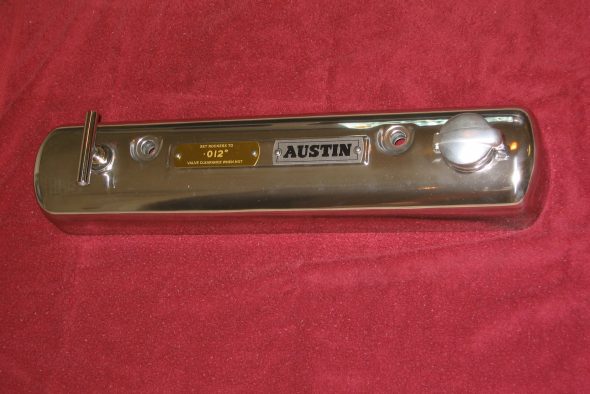
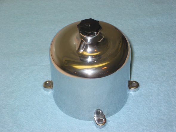
Rocker Cover and Carb Dashpots – The polisher finished his work about the same time the shroud work completed. Again, I was quite pleased with the quality of workmanship.

Capesport Rocker cover Polished

Carb dashpot polished

Shroud bodywork – Jeremy made some quick progress on the front shroud after getting it back from Craig. It is great to see some filler and primer on the aluminum!

shrouds primed 2

shrouds primed 3

shrouds primed 4

shrouds primed 1


Chapter 27 – Cleaning and Trial Fitting

December 14, 2005

Jeremy Turner’s Work Continues

Rocker Panel – Jeremy needed to do a little work on the rocker panels to get them looking just right. Then he fit the right rear fender so that the swage line would be properly aligned.

rocker panel fitted to fender_3

rh fender fitted_2

Since the tabs for the wiring harness in the boot were not installed with the new panels, Jeremy welded two in for me. Then he moved to the front right wing to get the bottom of the wing and shroud to align properly.

wire tabs welded_5

fender fitted at front_4

The left rear fender did not have enough of a lip on it to fasten the wing to the shroud so Jeremy welded in a little more material. He then spent a little time working out a few dents in the NEW wings! Following that he lined up the left door and the left rear wing swage line and moved to the left front wing to line up the shroud and wing at the front.

fender and door aligned_1

surround lined up with fender_4

The rocker panel on the right side needed some work at the front edge as well. Then Jeremy was able to epoxy prime all the wings.

Rear Wings in Primer

Front Wing In Primer

Front Wing Ready For Primer

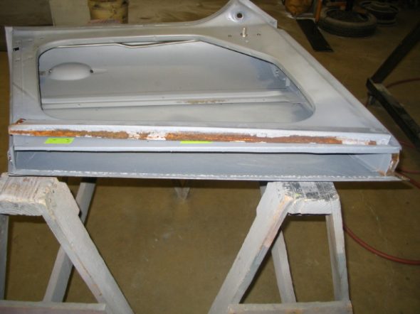
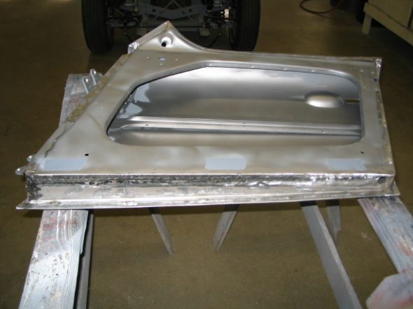
Although the doors had been epoxy primed some time ago, jeremy wanted to take the bottom of the doors apart to get rid of any rust at the bottom of the doors. 

Lh door bottom removed _3

Door Repaired

Jeremy then turned to bodywork with polyester filler. First was the boot lid.

Boot bodywork

Epoxy priming 2

Epoxy priming 4

Epoxy priming 6

February 2, 2006

Jeremy Turner’s Work Continues

Then came the bonnet.

Bonnet Body work

Epoxy priming 5

Back to the doors for filler and then primer.

Door work 1

Primed door 2

primed door 1

Then some more bodywork before priming again.

LH door body work completed_1

LH rear fender bodywork

LH rear fender bodywork 2

rear fenders primed 2

body work on lh fender_3

lh inside body work_2

rh fender body work_1

front wing body work 4


Chapter 26 – Cleaning and Trial Fitting

September 12, 2005

Jeremy Turner Begins His Work 

 We took the car to Jeremy in April, but he got stacked up during the summer months with the work of previous customers who wanted a few things done to ready their cars for shows of various types. Unfortunately, that meant pushing the BT7 off to the Fall.

To Maple Hill Restorations 1

Maple Hill Restoration Arrival 1

This week Jeremy got to work. First he media blasted and painted the seat backs and frames so that they could be sent to Heritage Upholstery for finish upholstery work. After I get Rick Kiser to build a new rear seat squab I will be ready to begin the waiting process for the interior work. I expect at least 2-3 months for that job.

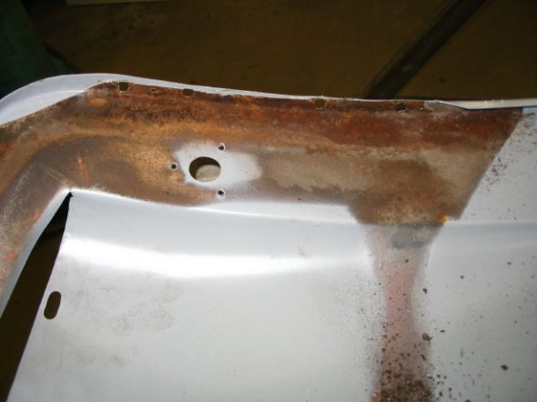
Jeremy began by fitting the doors and wings. Not as easy as it might have been since I am using new aluminum wings that don’t fit quite as nice as the originals, but the originals were consumed by rust. The bonnet had two holes punched in it for the installation of hood locks and we agreed that the holes needed to be filled. He cut the reinforcing frame off of the back of the bonnet to blast any rust from the skin, welded the holes closed and primed.

Latch brace removed_4

Underside of hood rust_7

Outside of latch brace repaired and cleaned_6

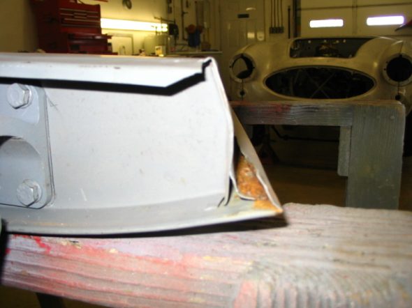
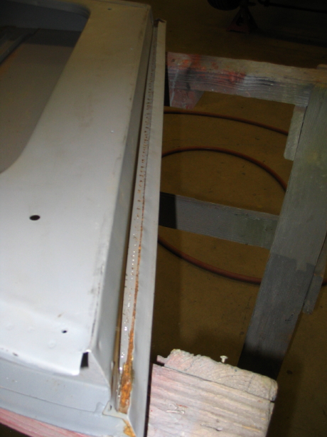
He also bent back the skin on the bottom of the doors to again get all the rust blasted out and primed. This will alleviate problems in the future. It is all a slow process, but it is what must be done to end up with the quality job I want!

Rust exposed on bottom door edge_4

Door edge lip pulled out to expose rust_3

Door edge glassbeaded to remove rust_2

Door edge epoxy primed_1

I received the windscreen frame from Custom Chrome Plating in PA. It was a beautiful chrome replating job. It should have been for $500.00 for four frame pieces! I took it and glass and hardware to Village Auto Center in Harrisonburg for assembly. I am nervous about their care, but I expect everything will come back fine.

September 20, 2005

The windshield came back and was nicely assembled except the corners don’t meet as tightly as they need to to prevent leakage. I will work on that later before final assembly. I put the pillars on the frame and will take it to Jeremy for fitting to the body.

Jeremy sent some new images of his latest work that focused on cleaning up the bonnet, fixing a dent and filling the lock holes.

Rear hood brace removed_4

Hood pin holes being welded_6

Screw holes welded up_2

Right hand hole welded up_1

Left hand hole shut up_3

Rust cleaned from underside of hood and dents removed._3

Body work done on underside of hood in areas that would be hard to get to when the braces are welded into place

Rear hood brace removed_4

Trunk brace removed_6

Trunk braces cleaned_8

Underside trunk lid cleaned

December 10, 2005

I have been disappointed that after a good start in September, Jeremy began working on other projects and didn’t make much progress with the Healey. He got back to work after Thanksgiving and forwarded the following photos of work done on the boot lid. It was badly deformed, cracked on the top side edges and didn’t fit the shroud particulalry well. I was pleased to see his skill with cutting and welding. Things are looking up!

adjusting LH trunk gap_4

adjusting RH trunk gap_5

new trunk edge to adjust gap

trunk edge removed

epoxy primed latch brace

underside epoxy primed

aligning the door and quarter gap

February 19, 2006

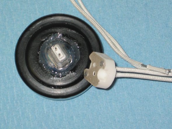
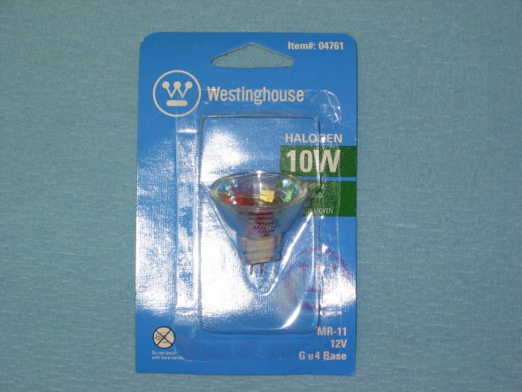
Rear lights on Healeys leave something to be desired. I came upon a web site that offered a good idea for adding some rear illumination without any obvious physical modifications. It involved converting the rear reflectors to working lights using a pair of 10 watt,12 volt MR11 halogen bulbs that I found at a local lighting store. I also ordered two connecting terminals on-line since the connectors are very small and somewhat delicate pins.

As per the directions on the Healey Club of Ontario web site, I removed the rear reflectors from their pods. I dicovered that this works with the original reflectors but not with those currently available! The reproductions are not as deep and do not have the foil reflector. The easiest way is to carefully insert a small screwdriver between the chrome bezel and the rubber ring. Pull the chrome bezel off, remove the red reflector, and the rubber body will easily pull out of the hole.

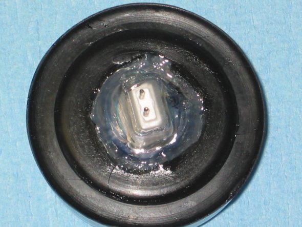
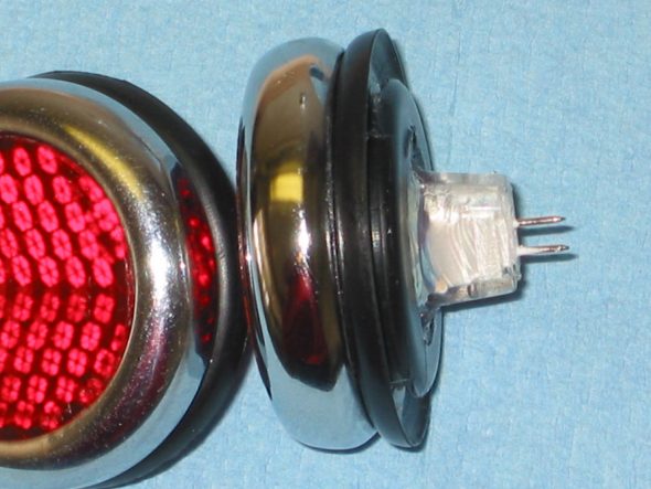
I removed the silver foil from the reflector and drilled a 1″ hole in the center of the rubber grommet. I then trimmed the hole to create an
inward taper into the reflector body to match the cone of the new bulb. Then I secured the red reflector to the grommet, sat the halogen bulb inside and pressed the assembly together. This is not real easy to do. I added a little dishwashing soap to the rubber to make it simpler to press things together. After assembly, I used a bead of silicone to seal the new bulb to the rubber grommet.

After installation on the car, run wires from the two brake light terminals in the trunk to each reflector pod and from the wire ground screws on each side to the same pod. The bullet connectors for the brake lights are in the boot on the driver side at the rear. I used bullet connectors and changed the single bullet holders to double so I did not have to spice into the wires. Driver side is White with Purple trace and Passenger side is White with brown trace. Since these will
light both with brake and turn signals this is important.

Rear modified reflectors 2

Rear modified reflectors 3

Rear modified reflectors 4

Rear modified reflectors 5

Halogen bulb


Chapter 25 – Cleaning and Trial Fitting

July 2, 2005

Control Head (Trafficator)

Well, I have been putting off the task of rebuilding the control head to preparte it for installation in my Moto-Lita wood rim steering wheel. I rebuilt the original control head when I was in college and I don’t recall it being a fun task. Although, back then I did so without any instruction. Today I have the benefit of helpful tips from Norman Nock, Michael Salter, Steve Byers, John Trifari and Tracy Drummond and others. The notes below and some of the images are “borrowed” from their work. Tracy’s photos were particularly helpful. 

For starters I now know that the way to begin is not to pry up the bent tabs at the back of the unit! Instead, the process is much simpler but less obvious. Turns out the whole job was not as bad as I had remembered.

In my case I needed to completely rebuild my control head because the signal lever was broken and because I needed to install new wiring. I also wanted to improve the finish of the Bakelite head which had turned a bit brown with age. If one only needed to replace the wiring the suggestions from Michael Salter proved to be very helpful. That was my first step.

Read through these instructions completely before starting the disassembly!! If you don’t want to try this then I understand that Vic Wright ([email protected]) does a great job of rebuilding used units!

On the steering wheel, you will see three set screws on the steering wheel hub, forward of the spokes. Loosen (probably remove, to avoid losing them) the screws. The four wires that go to the control head need to be disconnected from the harness at the front of the car not far from where they exit the long stator tube at the steering box. The job is made easier if one simply cuts the bullet connectors off the wiring and then solders a wire or ties fishing line to the wire. Having the line attached to the wiring will make inserting the new wiring much easier than it would otherwise be. The line should just rest in the steering column until the replacement is ready to install. The control head with a short stator tube and the wiring can then be removed from the steering column by pulling straight out (not twisting). Neil Trelenberg suggests drawing a line on the stator (short and long) tube with a felt marker as a guide for realigning later.

Now to the disassembly of the control head unit:

First, carefully pry the horn button trim ring away from the bakelite head being careful not to scratch it.
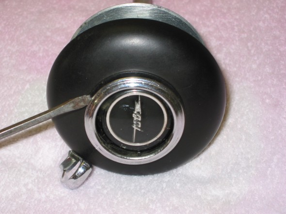
Trafficator Rebuild Image 1

Trafficator Rebuild Image 1

Once the horn button is loosened, the horn spring will be revealed. Its small diameter end faces to the bakelite head. The laminated blades of the horn switch secured by two brass screws also become evident.
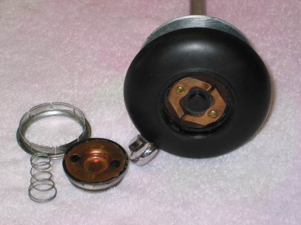
Trafficator Rebuild Image 2

Trafficator Rebuild Image 2

Examine the entire assembly. On the back of the unit, viewed from the side, a small tab bent down into a slot can be observed.
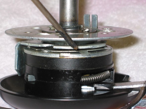
Trafficator Rebuild Image 3

Trafficator Rebuild Image 3

The tab can be pushed up so that it slides on the flat plate and the unit can be rotated slowly. Doing so provides access through 3 holes in the base mount plate to 3 slotted screws.
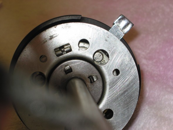
Trafficator Rebuild Image 4

Trafficator Rebuild Image 4

Before removing the three screws, make a note or reference mark of how the two halves of the unit secured by the three screws goes together. Then remove the screws. The correct orientation of the turn signal lever is straight up, but if the two halves are oriented incorrectly, the turn signal lever will be either pointed down, or off to the side.
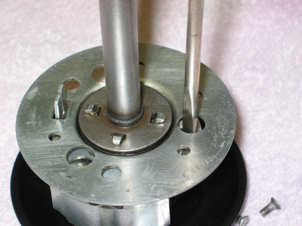
Trafficator Rebuild Image 5

Trafficator Rebuild Image 5

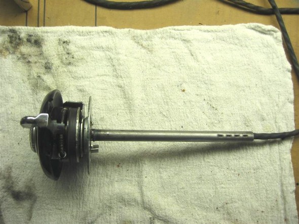
The stator tube, base plate, locating plate, the base mount plate and assorted washers and spring can then be separated from the bakelite mounting plate and head. This assembled unit does not need to be disassembled. It can be pulled off the wires and set aside for assembly later.
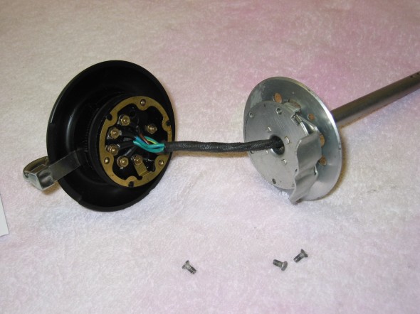
Trafficator Rebuild Image 6

Trafficator Rebuild Image 6

Examine the back of the mounting plate. There are six nuts visible. Three are for the turn signal switch, two are for the horn (one goes through the brass gound ring) and the one without an attached wire is to hold the head and the mounting plate together (It is barely visible in the photo under the wiring sheath). Make a drawing to illustrate the color code and where each of the wires should reconnect to its proper fitting.
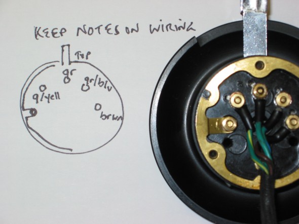
Trafficator Rebuild Image 7

Trafficator Rebuild Image 7

If your plan is to install a new wiring harness only and you do not wish to disassemble the control head to access the turn signal switch it is IMPORTANT to install the new wires onto the screws one wire at a time.

A. The screw on the right in the photo is accessed under the horn button. Hold it with a screw driver and loosen the nut holding the wire, remove the nut, change the wire, refit and tighten the nut.

B. The nut second from the right is held in place by a hex head screw recessed in the bakelite mounting plate. The turn signal lever must be moved so that it is aligned behind the screw/nut. It will hold the screw in place permitting removal of the nut and old wire, change the wire and refit and tighten the nut. Do not let the turn signal lever slip while doing this procedure or you will likely be disassembling the complete unit!

C. Reposition the turn signal lever to the center position and repeat B. above for the screw/nut located third from the right.

D. Move the turn signal lever behind the screw/nut located fourth from the right and repeat B. above.

If all you are doing is replacing the wiring you are finished. Leave the screw/nut to the far left, through the horn ground ring, alone.

Feed the wire through the base plate and the stator tube. Reinstall the three base plate screws with the trigger opposite the turn signal lever. I found it easiest to install the screws with the unit on its side. Don’t forget to then reposition the thin plate with the locating tab to the slot and push it down. Reinstall the horn button, spring and chrome trim ring. Note that the button and ring have a locating notch that matches up with the bakelite head.

I recommend cutting the bullet connectors off the wires, solder the wire or tie the fishing line left in the steering column, to the new wires and slowly pull the new wiring harness through the stator tube and out the end of the steering box. The fit of the harness in the tube is tight so it might be best to tape the wire ends together as they are pulled through. The short stator tube fits down and into the longer stator tube in the column. The tubes go together in only one orientation, directed by the dimples found on the side of the short tube.

If you are installing the control head into a non-stock wooden steering wheel you may need to install a shim (I used the plastic top of a yogurt container) inside the hub between the hub and the control head to move the control head toward the driver slightly so that the turn signal lever does not contact the wheel ring. Then reinstall the three set screws to tighten the control head to the wheel hub.

Cleaning or repairing the turn signal mechanism. 

Remove the two screws holding the laminated blades of the horn switch under the horn button. The horn switch will lift out. The third screw can then be removed and the bakelite head can then be separated from the mounting plate.
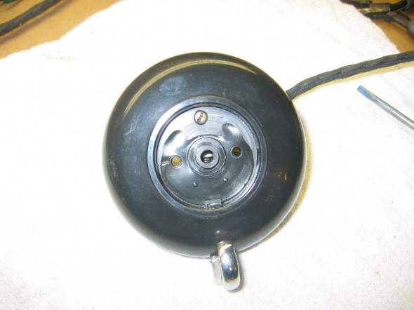
Trafficator Rebuild Image 8

Trafficator Rebuild Image 8

The turn signal lever is attached with one screw to the back of the bakelite mounting plate. Underneath it is a curved wire with a spring on each side of the lever.
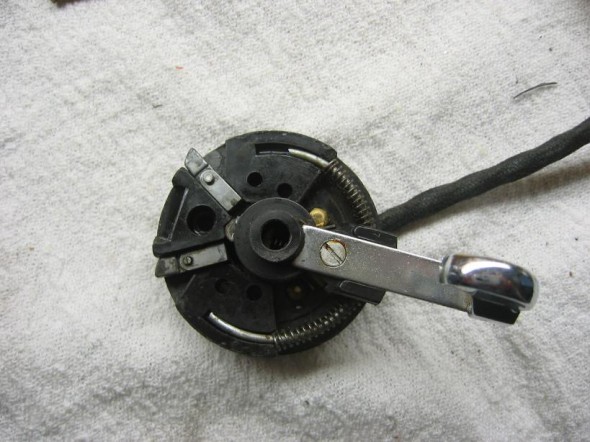
Trafficator Rebuild Image 9
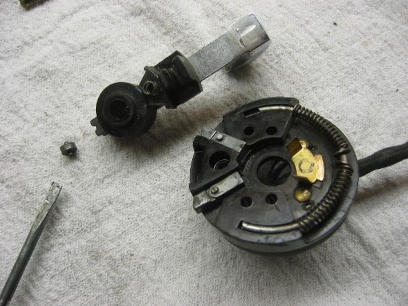
Trafficator Rebuild Image 9

Trafficator Rebuild Image 10

Trafficator Rebuild Image 10

There is another little spring and ball at the bottom of the turn signal lever.
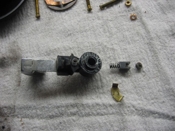
Trafficator Rebuild Image 11

Trafficator Rebuild Image 11

If you carefully remove the single screw to separate the  lever from the assembly, the springs and small parts should stay in place. Note how they should be reassembled, then take apart, clean and lubricate with a little lithium grease.
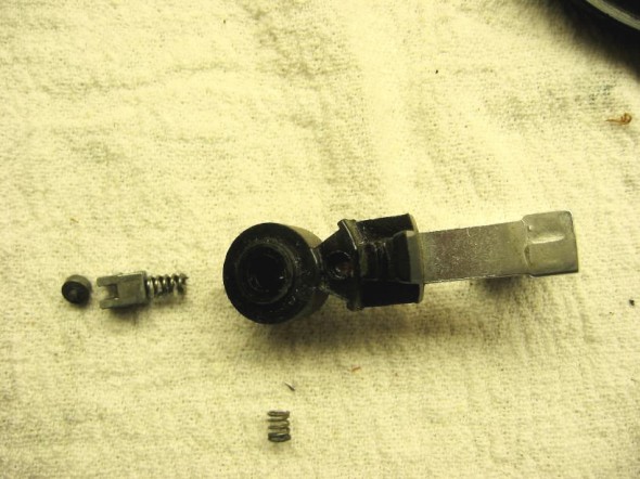
Trafficator Rebuild Image 12

Trafficator Rebuild Image 12

If you experience an explosion of parts, don’t be alarmed. It will all go back together! All components are identified in the photo below:
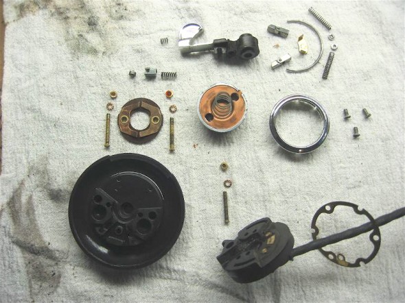
Trafficator Rebuild Image 13

Trafficator Rebuild Image 13

The proper positioning of the two hinges or “triggers” is important. They have angles on the end that fit opposite each other. They need to be placed as seen in the image and drawing for the canceling switch to work. Before reassembly of the complete unit, now is a good time to refinish the bakelite if it is needed.
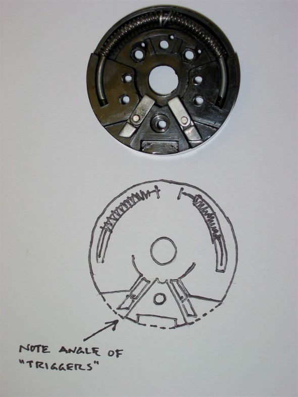
Trafficator Rebuild Image 14

Trafficator Rebuild Image 14

Refinishing the Bakelite Head

I have lost the source of these instructions or I would give attribution, but clean the head well and wipe with a liquid cleaner like the type used before spray painting metal. Then apply black India ink. I used two coats letting the first coat dry for about an hour before applying the second. Then use black paste shoe polish rubbed in well. Polish. Reapply paste and polish again. Finally, apply a coat of carnuba wax for protection and final shine. Be very careful to not drop the bakelite head! I recommend doing all the polishing over a carpeted floor in case the head is dropped. This should result in a control head that looks brand new.
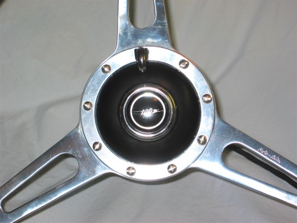
Trafficator Rebuild Image 15

Trafficator Rebuild Image 15


Assembly

Carefully place the head and the mounting plate together pushing the spring at the end of the turn signal lever into the mounting plate. Holding the two pieces together install and tighten the single screw and nut at the bottom of the unit. This screw/nut will securely hold the two pieces together while the horn switch screws and nuts are inserted and tightened.
Trafficator Rebuild Image 16

Trafficator Rebuild Image 16

I recommend, based on the comments of others and my own experience, cutting the bullet connectors off the wires, solder the wire or tie the fishing line left in the steering column, to the new wires and slowly pull the new wiring harness through the stator tube and out the end of the steering box. The fit of the harness in the tube is tight so it might be best to tape the wire ends together as they are pulled through.

Steve Byers took a slightly different approach that certainly makes taking the wiring through the stator tube easier. He commented, “although I have been able to pull the harness out of the column with the connectors installed, I have never been able to put it back in no matter how tightly I taped/wrapped the connectors together.  The last time I did this, I installed a new steering column harness as a part of a general re-wiring.  To make it easy on myself, I cut off all the bullets from the new harness (leaving about 3/4″ of the wire attached to each), fed the harness through, and then soldered the bullets back on with a piece of heat-shrink tubing over the splice.  The key is, I did not twist the wires together before soldering but soldered them together as they lay side by side.  That way, next time the harness needs removing it will be easy to remove the bullets without damaging the wire, and that can be done many times without damage to the wires.”

The short stator tube fits down and into the longer stator tube in the column. The tubes go together in only one orientation, directed by the dimples found on the side of the short tube.

If you are installing the control head into a non-stock wooden steering wheel (Moto Lita, Derrington) you may need to install a shim (I used the plastic top of a yogurt container) inside the hub between the hub and the control head to move the control head toward the driver slightly so that the turn signal lever does not contact the wheel ring. Then reinstall the three set screws to tighten the control head to the wheel hub. The job is complete! Now the control head (horn and turn signal control switch) will look and work as well as the rest of your car.

Roger Moment’s tips for installing a new steering wheel or repairing the trafficator without removing the wiring.

For those who are really bold and experienced Roger Moment has informed me that it is possible to complete a trafficator repair or replace a steering wheel without having to pull the wires up through the stator tube. I have no personal experience with this approach so I cannot comment on the degree of difficulty, but if Roger says it can be done, then it can! However, he emphasized that it should only be attempted by those who are totally familiar with the disassembly of these units.

The relevant steps are:

Unclip the end of the steering column harness so that there is about 8″ or more of slack.  This is accomplished by locating the clip that holds it to the cross brace in front of the radiator.

Back off the three retaining pointed screws in the steering wheel hub.

Pull out the head enough so that it can drop down across the front of the steering wheel.

Push up and rotate the retaining tab as seen in Image #3 and below in Image 17.
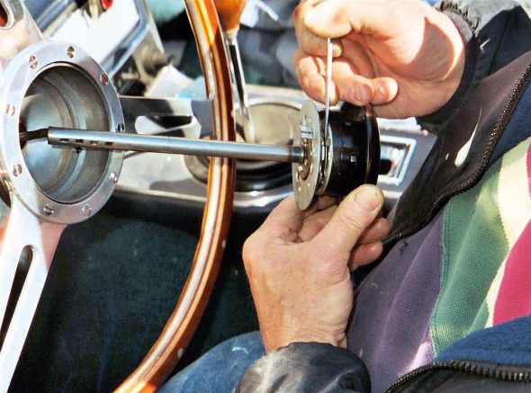
Trafficator Rebuild Image 17

Trafficator Rebuild Image 17

Remove the three screws securing the mounting to the backing plate.
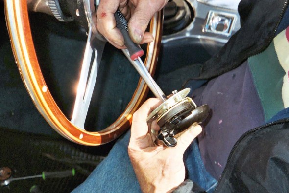
Trafficator Rebuild Image 18

Trafficator Rebuild Image 18

Then separate the backing plate:
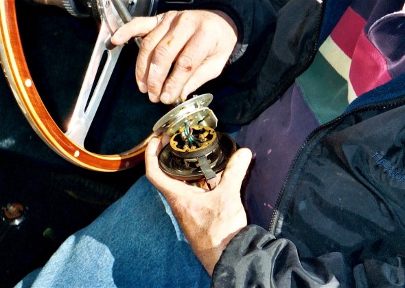
Trafficator Rebuild Image 19

Trafficator Rebuild Image 19

One can then remove the wires as described earlier in this article, using the technique with the lever to “back up” the contacts so that they don’t fall into the head.  It is very important to replace the nuts immediately after removing each wire!

Once the wiring has been removed from the switch assembly, if you are only going to repair it you can leave the wire loom in place in the short sliding part of the stator tube. However, if you are planning on removing the steering wheel to replace it, you must first draw the wires back through the short tube.   This is easily done by first folding only twoof the eyelets tightly back against the wires, leaving the other two extending straight. This creates a “package” that is compact enough to slide through the tube.  Next remove the circlip and pull the steering wheel off the shaft.
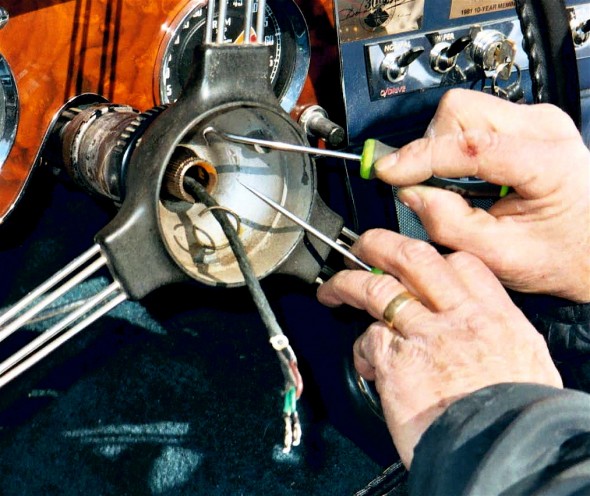
Trafficator Rebuild Image 20
Trafficator Rebuild Image 20
Roger indicates that this “in-car” method will also work on non-adjustable steering set-ups (on 100s and those few 6-cylinder cars that are equipped as such).  However, here the entire stator is drawn up after loosening the clamping nut. The steering box oil will drip out around the wires at the end during the time that the tube is partially withdrawn. As soon as the wires are freed, the tube can be re-inserted and the nut re-tightened.  You’ll only lose a bit of the oil and it still beats reinserting the entire tube.

Roger suggests that if you do draw out the tube, use a 3/8″ bolt with a good 1″ or so of smooth shank to re-insert into the nut and olive at the steering box to keep most of the oil from draining out.  This bolt is then removed when the tube and wires are put back through.

Happy Healeying and Cheers!

Lin Rose

1960 BT7

1959 Bugeye


July 7, 2005

Revised October 2, 2005

Click this link for a pdf of the trafficator rebuild: Trafficator Repairs Low Res


Chapter 24 – Cleaning and Trial Fitting

February 12, 2005

Fitting Shrouds and Wings 

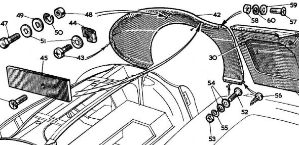
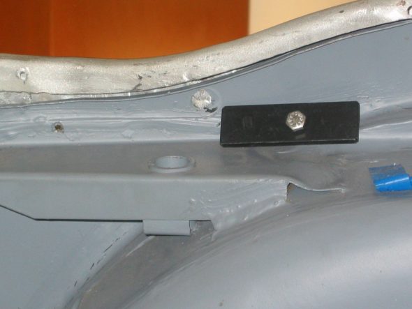
Rear Shroud –After removing all small components from the car I secured the shrouds and wings to the car to prepare it to go to Jeremy Turner for panel fitting and painting. To get the shroud and wings lined up properly, the rear shroud first needs to be riveted to the frame. There are a number of sheet metal screw holes in the superstructure and the shroud that Martin used to position the shroud, they are not needed for final installation.

In addition to the rivets, there are six #10 –32 x 1/2” flat head screws and nuts inside the top rear lip of the boot lid channel. Four of the screws attach through the two steel metal clips that provide support for the boot lid hinges.

rear fender fasteners

Rear wing securing plate 1

Wing right rear 1

Wing right rear 3

Wing right rear 4

Wing right rear 2

Front Shroud – Installed 3 flat head #10 x 1/2” machine screws in lip at front of the bonnet channel. Must catch the bottom frame rails on the inside first, then angle the back of the shroud up in the air – not easy to do!

Installed 5 flat head #6 x 3/8” sheet metal screws in lip at back of bonnet channel.

Installed two flat head #10 x 1/2” machine screws on each under bonnet vertical bracket. Couldn’t fasten properly on the left side because of the misformed panel at the left front corner of the superstructure.

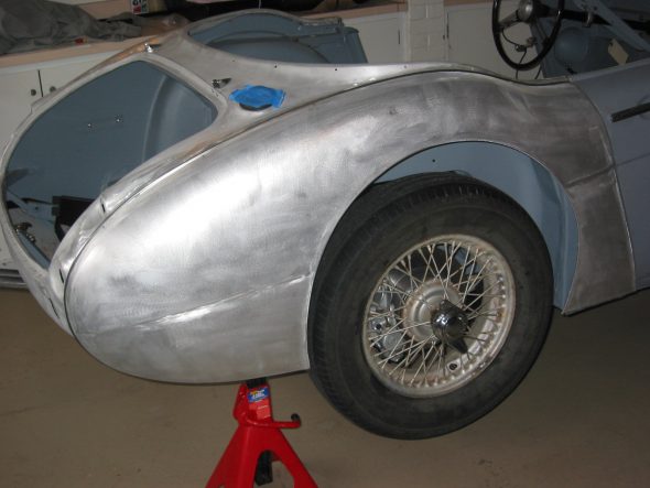
Front Wings – Started with the fastener closest to the headlight. Then fastened the rearmost fastener. The long screws are used on the top of the wings. The clips with the shorter screws are used at the front of the wing by the turn signal lights.

Wing Right Front flange1

Wing Right Front flange 2

Car with wings 1

Doors – Pulled the door up and out and then tighten the hinge screws. May need to do some shimming to align correctly.

June 19, 2005 

Side Curtains – I determined that It was better to purchase new side curtains rather than restoring my old ones. However, while the new frames looked quite good, I thought the old rear brackets were better formed than the new brackets. To dress them up and avoid rust in the future, I decided to chrome plate the old brackets.

Chrome Plating 

I sent a number of parts to Custom Chrome Plating in Pennsylvania for plating. Some were for replating and others were items that I just decided to chrome. I am a little concerned about getting too much plating in the windscreen frame channels but it will hopefully turn out alright.

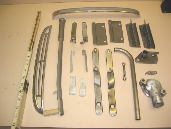
1 Breather Pipe

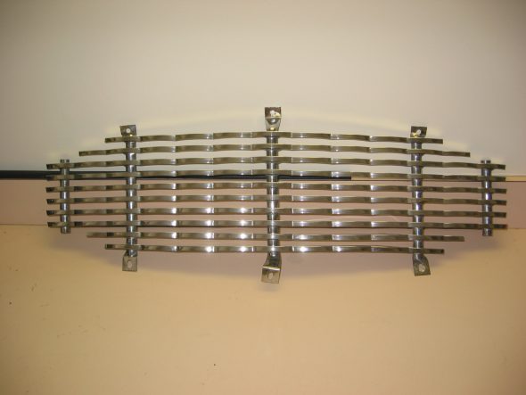
1 Bonnet Grille

1 Bonnet Grill Surround

1 Interior Dash Grab Handle

1 Interior Dash Grab Handle Escutcheon

2 Boot Hinges (2 pieces each)

2 Rear Seat Squab Retaining Channel Assemblies (2 pieces each)

1 Handbrake Handle

1 Handbrake Pawl

1 Handbrake Ratchet Plate

1 Thermostat Cover

2 Rear Seat Back Hinge Hardware (2 pieces each)

1 Windscreen Frame (4 pieces)

1 Front Grille

1 Boot Spare Tire Strap Staple

2 Side Curtain Brackets (2 pieces each)

Parts to chrome 2

Parts to chrome 10

Rear Seat Squab 

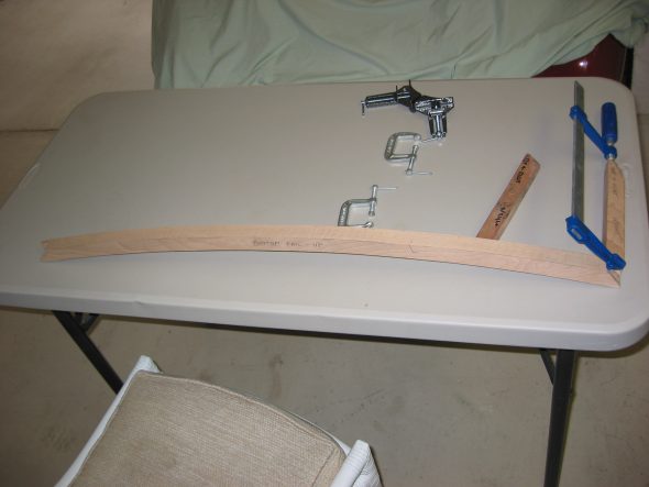
When I owned the car as a twenty year old I decided that rear speakers in the squab were more important than originality! I have decided to have the squab rebuilt by a local carpenter (He made the pieces and I put it together) before sending it to Heritage Upholstery and Trim for upholstery.

Rear Seat Squab assembly

Rear Seat Squab assembly

Rear Seat Squab assembly

Rear Seat Squab assembly

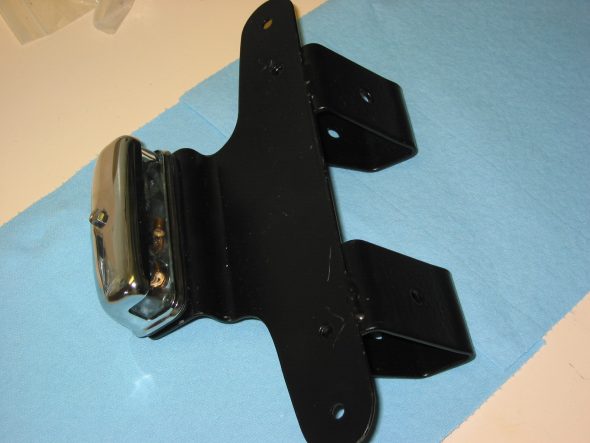
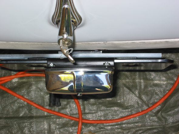
Rear License Plate Bracket and Lamp 

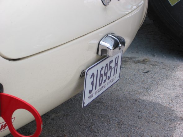
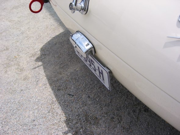
Since I am using Rally car bumpers rather than the original full bumper I need to develop a new approach to mounting the plate and the lamp. I had fabricated something myself, but then decided to modify the BJ8 bracket and mount it directly to the car. I saw another approach on Aussie Peter Jackson’s BN7 at VIR and I may still do something like his.

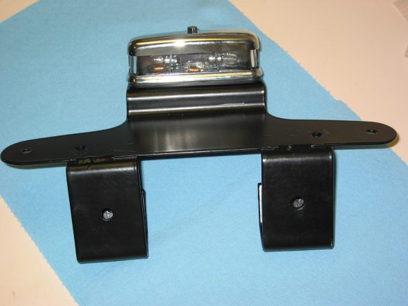
license & Lamp bracket 1

license & Lamp bracket 2

license & Lamp bracket 5

Peter Jackson’s car:

Peter Jackson’s Plate 

Peter Jackson’s Plate

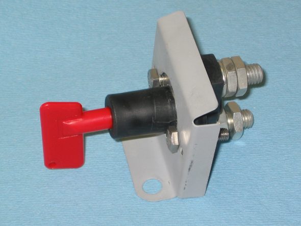
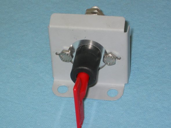
Battery Master Switch 

So many have complained about problems with the original master switch that I decided to replace it with a modern equivalent from Hella. I mounted it in the original switch bracket.

Battery Master Switch 1

Battery Master Switch 2

Chapter 23 – Cleaning and Trial Fitting

January 15, 2005

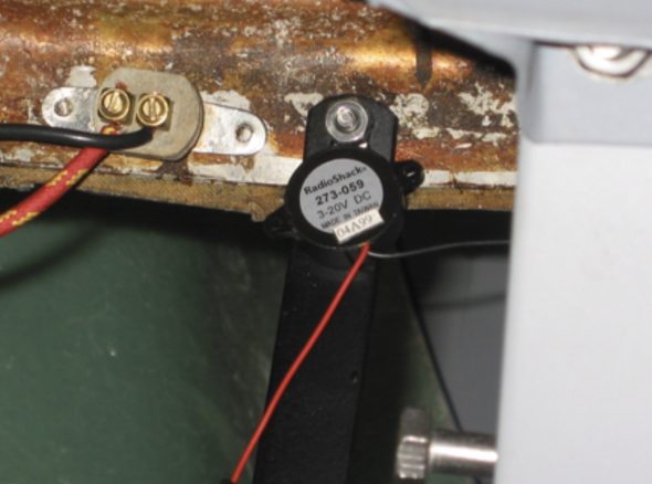
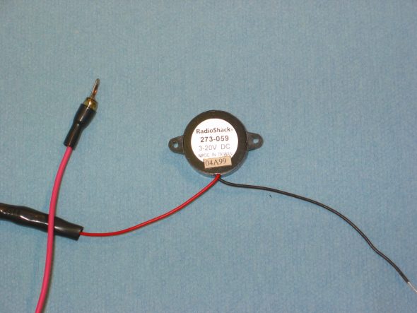
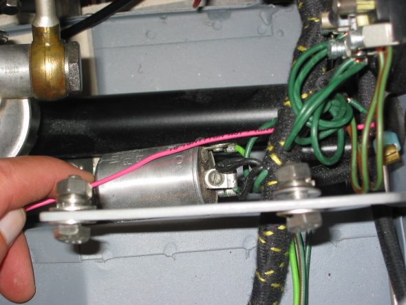
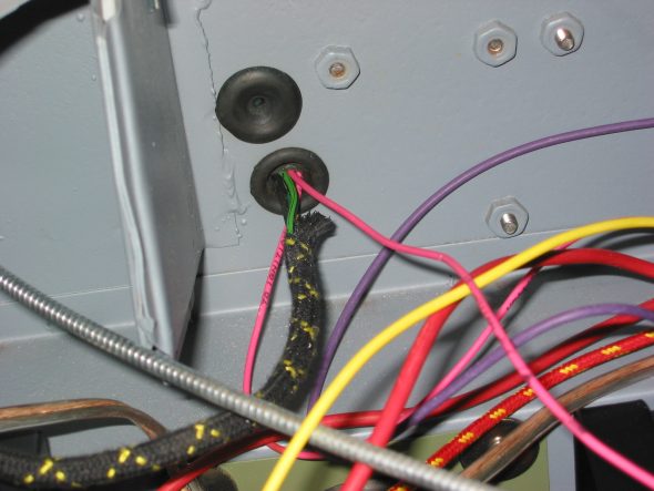
Turn Signal Audible Buzzer – I had used a little buzzer produced by Radio Shack in the Bugeye and decided that I would add one in the Big Healey also. I will just use a little 3M double sided sticker to fasten it to the fascia support bar since it is so light. That will get it as close as possible to the driver. The buzzer has 2 wires. Red wire is joined to a pink wire that is routed through the firewall and connected to the center post on the flasher canister. The black wire is grounded by connecting it to the fascia support bar screw and nut.

Buzzer Mounting

Signal buzzer radio shack

Signal buzzer connection

Signal buzzer wiring

January 22, 2005

Other Accommodations to Modern Technology

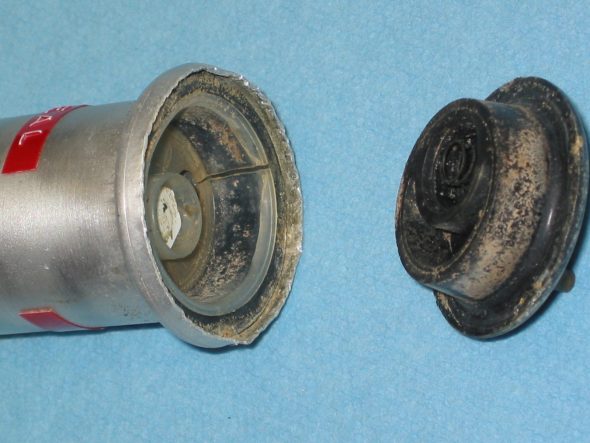
Electric windscreen washer – I read a technical article by Stu Brennan, an owner of a Sunbeam Tiger, who had converted his hand activated pump windscreen washer to an electric washer. I liked the idea because he put the electric switch in the aluminum pump canister thereby eliminating the need to install an additional switch somewhere. Since the washer in the Tiger is the same as the one in the Healey I decided to give it a try.

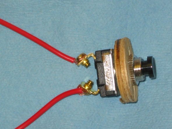
Two items needed to be purchased for the conversion. As Stu did, I used an electric pump purchased at an AutoZone, part number 9-300 from TAAP Corp. I purchased a Home Depot switch, Gardner-Bender, Push Button, GSW-22, SPST always-off.

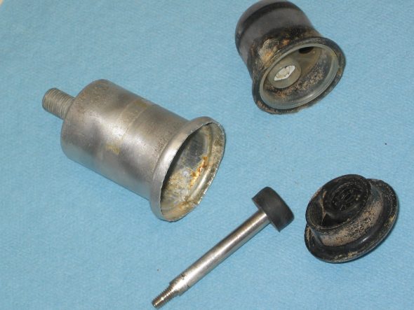
The old pump was easily disassembled by un-crimping the lip from around the plastic bottom. The metal is relatively soft, so it unfolds easily. The bottom and the old rubber bellows came right out, leaving only the plunger within the shell of the pump.

Windscreen washer pump 2

Windscreen washer pump 3

To provide stability for the switch in the canister and to use as a spacer I cut a circle washer of 1/4” wide plywood that fit tightly in the canister and placed it on the switch secured with double nuts.

Windscreen washer pump 4

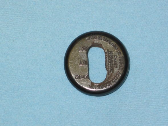
To provide enough depth for the switch in the canister I cut a slot in the plastic face plate. The slot also provided space for the switch wires to exit the canister.

Windscreen washer pump 5

Power comes from a switched terminal on the ignition switch, and is connected to the new red wiring through an in-line fuse holder. From the other side of the switch, a new red wire carries power to the white wire on the pump. The “negative“ side – black wire –  of the pump is grounded at the mounting bracket.

The connectors for the water tubing on the pump are larger than that used on the shroud fittings and the tube from the reservoir. I purchased a plastic transition piece that fit the larger fitting on the pump and the smaller fittings elsewhere.

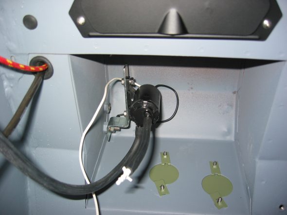
I mounted the pump in the interior in the right side pedal box space. At that location it is virtually impossible to see. I made a small bracket that allowed me to secure the pump to one of the 1/4” bolts that is used for the throttle shaft bracket if it were a RHD car. I did replace the 1/2” blanking hex bolt with a 1” bolt, giving enough length to fit the bracket.

Windscreen washer pump

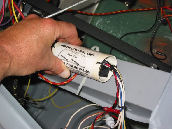
Intermittent Wiper Control – Ed Esslinger, a member of the TigerUnited club designed and built a wiper control unit to provide intermittent wiping of the windscreen and made them available for sale. [email protected]  334-774-5155.

The green wire TO the wiper motor must be disconnected so that the delayed 12V can be applied to it from the Wiper Control (WC) unit. Disconnect the battery.
Disconnect the black/green wire from the dash switch. Connect the white/yellow wire from the WC to the switch terminal where the black/green wire was removed.

Connect the red/yellow wire from the WC to the black/green wire that was disconnected from the switch.

Connect the black wire from the WC to the terminal on the wiper switch that already has a bleck wire, which must be left connected. (Black wire can be connected to any good ground point.)

Reinstall the wiper switch to the fascia.

Route the long white/blue wire from the WC to the wiper motor. Connect the green wire from the motor to the white/blue wire.
Route the long white/green wire and the white/brown wires from the WC through the grommet in the firewall. Connect the white/green wire to the fuse block terminal with the other green wires. (switched 12V). Connect the white/brown wire to the to the fuse block with the fused side – brown wires, this is the unswitched 12V. It may have purple wires attached to it.
I then mounted the WC to the steering wheel bracket with a plastic tie strap. 

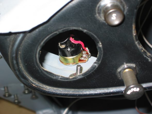
Intermittent wiper 1

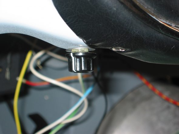
I mounted the remote interval control on the fascia bottom to the left of the wiper switch. Reconnect the battery.

Intermittent wiper switch 2

Intermittent wiper switch 1

Testing procedure

Wet the windscreen. Make sure the remote control and the wiper switch is turned off. 

Turn the ignition on.

Turn on the wiper switch – wipers should work normally.

With the wiper switch on, turn off the ignition switch. Wipers should continue to run and park themselves.

With the wiper switch still on, turn the ignition back on. Wipers should not operate.

With the ignition still on, turn off the wiper switch for a few seconds. Place the wiper switch on. Wipers should now work normally.
With the wiper switch on, rotate the remote interval clockwise. After a few seconds the wiper will operate in the intermittent mode, and can be adjusted to run from a few seconds to about 60 seconds.

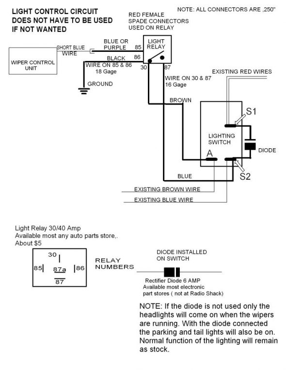
Controlling the Headlights when the wipers are onEd’s kit also provides a connection to permit the headlights to be turned on when the wipers are turned on. Directions for the relay are provided below:

100-6 headlight control_1

February 12, 2005

More Modifications for Comfort

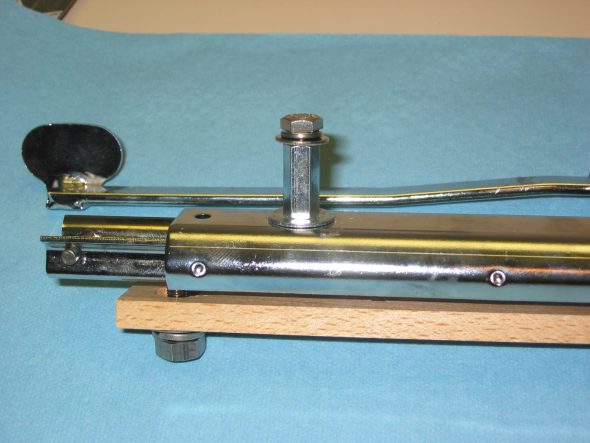
Driver’s Seat Angle Adjustment – I borrowed an idea from someone on the healey list-serve to make driving the 3000 a bit more comfortable for a person over 6 feet. I purchased 4 “couplers”, 1/4”-28 x 7/8.” 

On the most forward (closest to the steering wheel) studs on the seat rail mechanisms, I simply screwed the coupler onto to the stud. After the seat is in place the coupler is secured with 1/4” – 28 x 1/2” hex bolt (flat and lock washer).

On the middle stud, I cut the coupler so that is was approximately 1/2” long. I then cut off the stud on the seat rail so that it was only about 3/8” long. I then screwed the coupler onto the shortened stud and secured it to the seat frame with another 1/4”-28 x 1/2” hex bolt.

Finally, the third seat rail stud is left as is and the seat frame is attached secured with a 1/4”-28 nut with washers. 

Seat Rail riser 2

Seat rail Riser 1

This modification slightly tilts the driver’s seat to the rear providing a little extra shoulder/arm reach to the wheel. I found the new position more comfortable. I decided against the modification for the passenger seat fearing that it might cut leg blood circulation unnecessarily. The visual appearance is only slightly different and probably only noticed by those who knew what was done.

Carpet Installation 

I received my Wilton Wool carpet from Heritage Upholstery and Trim. Everything looked great – very high quality. However, I was disappointed that the light beige carpet color was not exactly what I was looking for. I have decided to switch colors and will order black carpet for an all black interior.

Although I wanted to go ahead an install the snaps on the floor boards and the gearbox cover before the car was painted. I decided to wait until final assembly. I really didn’t want to position the larger floor mat pieces until the footbox and siderail pieces were glued in place to insure the proper overlap and fitting in general. Since I cannot do the gluing of the smaller pieces until final assembly, I will just wait on this little project.


Chapter 22 – Cleaning and Trial Fitting

January 1, 2005

Soft Top Frame 

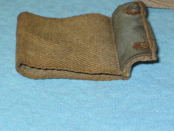
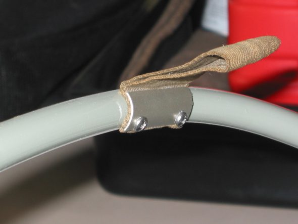
Installed the webbing pull tabs on freshly painted brackets. Used four number 6 stainless sheet metal screws to the frame.

Soft Top Pull Strap

Soft top frame webbing 1

Hardtop Headliner Installation 

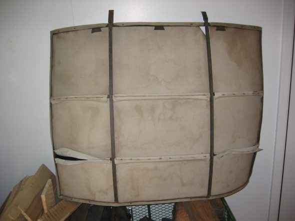
Hardtop Headliner – I took the unrestored headliner on its frame to Gerry Smith at Classic Upholstery to have him look at it before I took it apart. He will install the new headliner on the frame. The fabric came from Bill Bolton. Gerry was ready for the task so I headed home to take things apart to clean up and paint the frame. 

Headliner old – on frame

Headliner-old- on frame 4

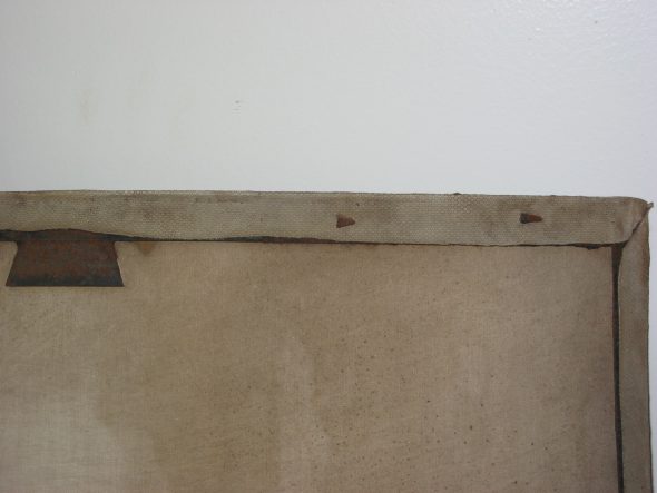
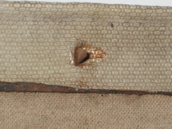
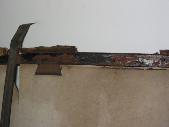
I bent back the securing tabs on the inside of the frame rails. There were six tabs on the front rail, all bent to the right. On the right vertical rail there were 3 tabs all bent down. On the left side there were also 3 tabs, but they were bent up. The bottom rail had 6 tabs, all bent to the right.

Headliner-old- on frame 8

Headliner-old- on frame 9

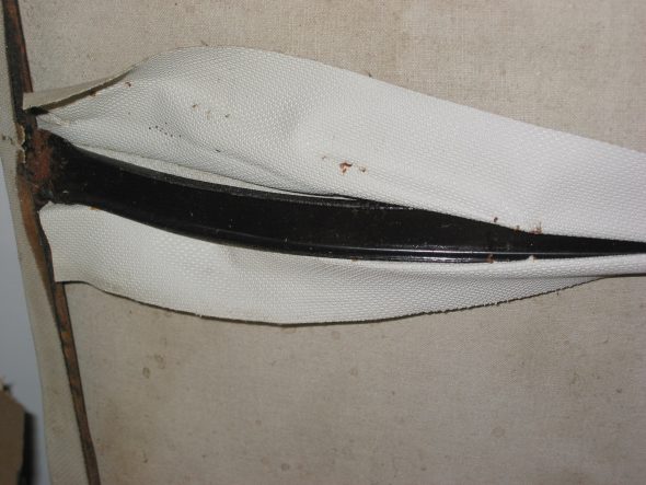
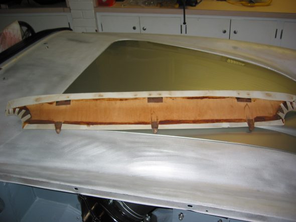
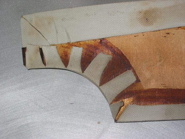
The headliner is actually three separate pieces of fabric sewn together and fastened to the frame with staples. The extra material at each seam is folded around the frame rails. There were approximately 6 staples in each section.

Headliner-old- on frame 2

Headliner-old- on frame 5

Headliner-old- on frame 6

Headliner-old- on frame 7

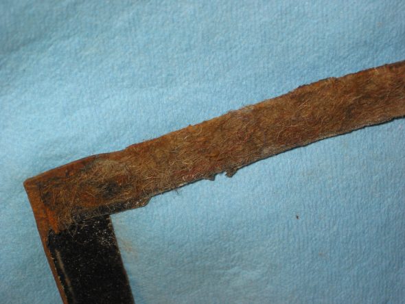
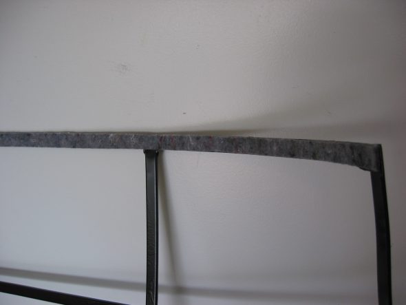
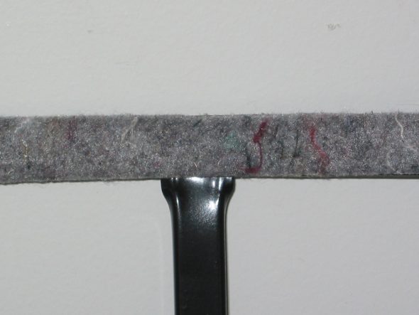
Hardtop Headliner Frame – The frame rails had contact cement on them to secure the fabric in addition to the tabs. The rear rail had felt on the inside (toward the headliner & interior).

Headliner-old- on frame 10

Headliner-old- on frame 11

Headliner felt on frame 1

Headliner felt on frame 2

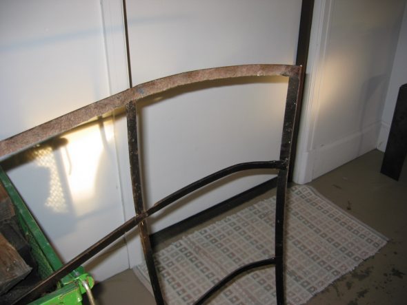
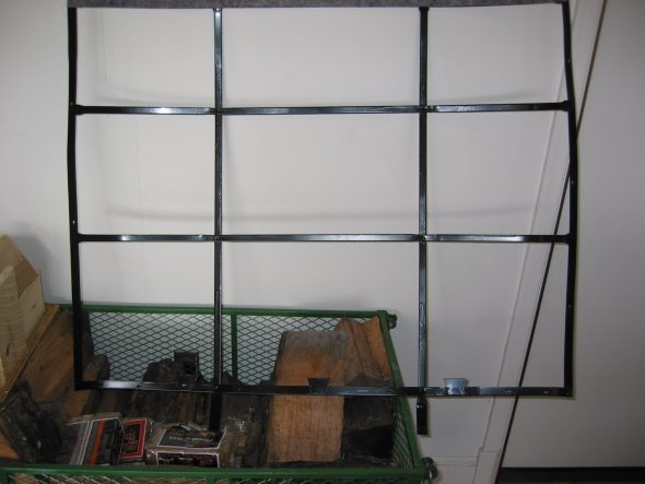
Cleaned up! Painted and new felt.

Headliner frame restored

Headliner frame new felt

Headliner new felt 2

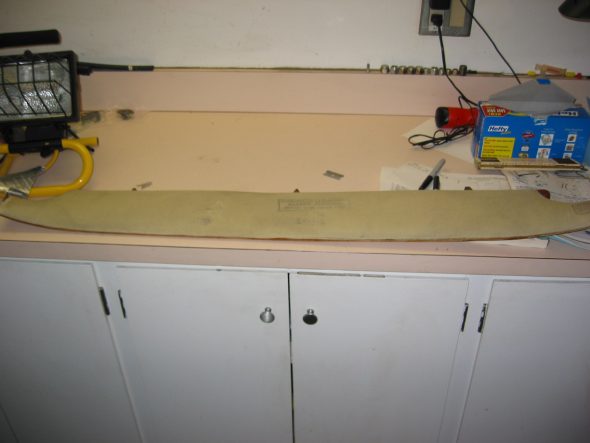
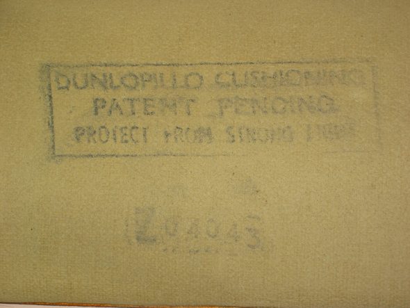
Hardtop Headliner Front Pad – Then I went to work on the front pad for the headliner. The foam rubber was in remarkably good shape for 45 years old! It will be fine to use again. It was apparently made by an Italian division of Dunlop?

Headliner front pad 1

Headliner front pad 2

Headliner front pad 4

Headliner front pad 5

Headliner front pad 8

Headliner front pad 9


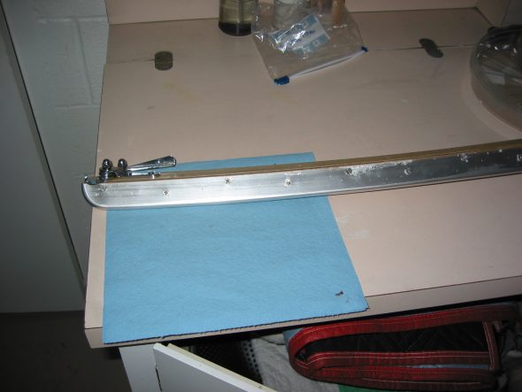
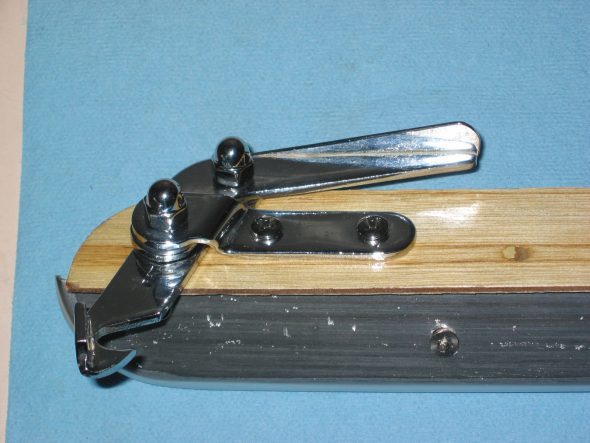
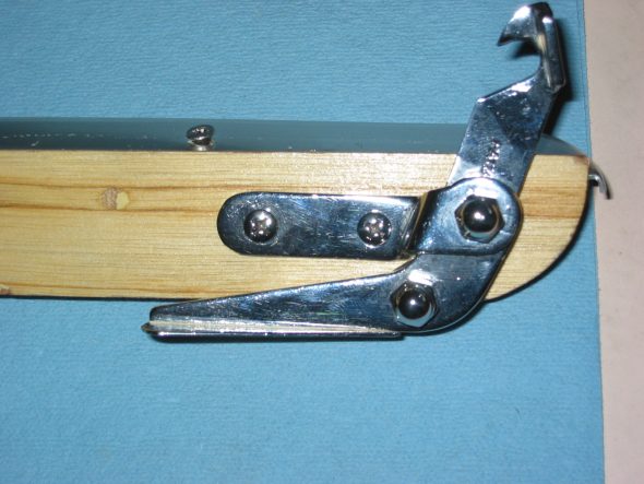
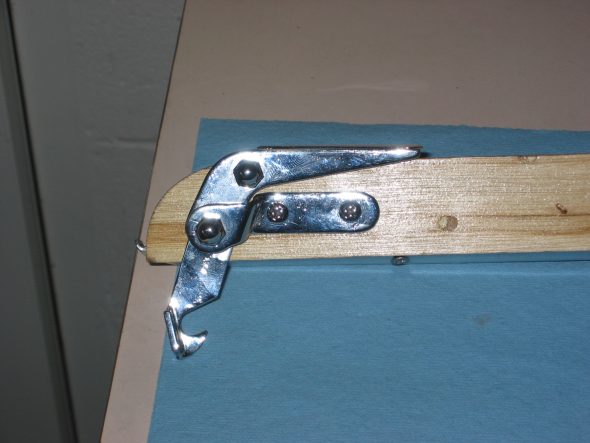
Soft Top Front Rail – Finished the assembly of the convertible top front windscreen bow. Fastened the aluminum front rail with 15 1/2” flat head stainless screws. Cleaned and reassembled the two fastener clasps and mounted them to the bow with 3/4” #10 pan head screws.

Soft top bow rail

Soft top bow clasps 1

Soft top bow clasps 3

Soft top bow clasps 2

January 2, 2005

Interior Courtesy Lights 

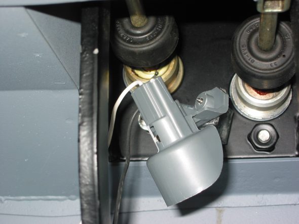
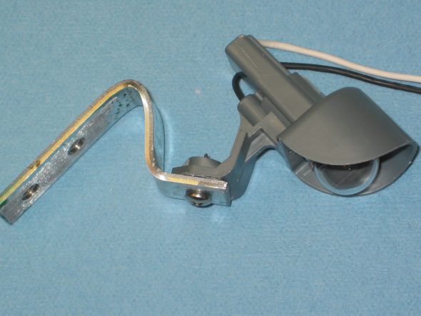
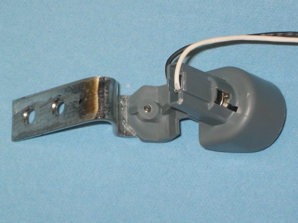
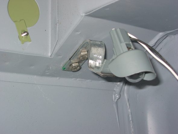
I fabricated mounting brackets for each of the lights for the interior footwells. I mounted the driver’s side bracket to the clutch master cylinder lower mounting bolt to avoid having to drill any new holes in the car. This required using a 11/2” 5/16” bolt rather than the customary 1” bolt. The right courtesy light bracket was mounted to the 2, 1/4” fixed nuts for RHD throttle pedal mounts. Also done to avoid drilling any new holes.

Courtesy light left 1

Courtesy light right 1

Courtesy light right 2

Courtesy light right 3

Courtesy light right 4