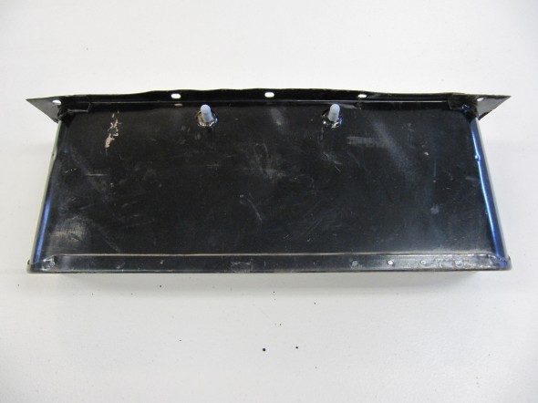
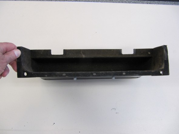
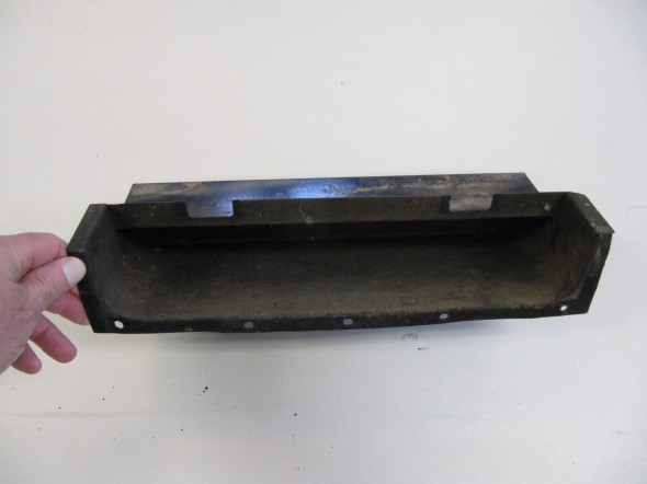
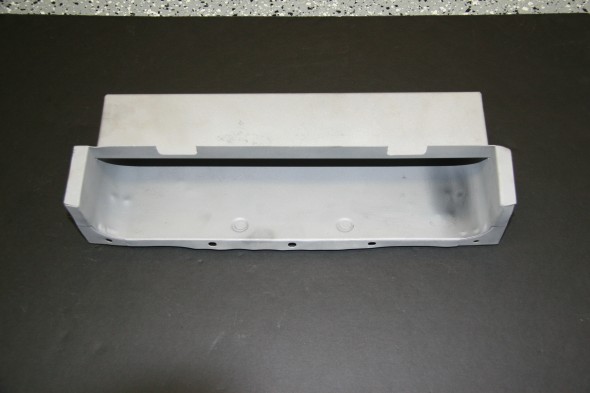
“Cubby” Glove Box

“Cubby” Glove Box

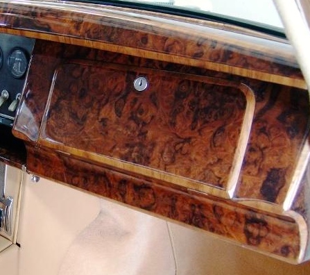
The “Cubby” as the glove box is referred to is located on the RH side of the dash fascia.

Cubby Door

Cubby Door

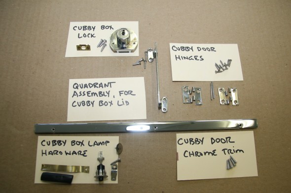
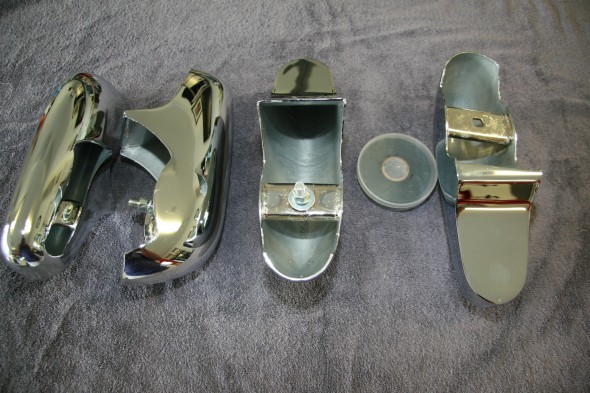
It has a hinged wooden door and the box itself is a heavy cardboard material. My original is in excellent shape but unfortunately suffers from a lingering musty odor from years of damp car storage so I will not be able to use it. The image below shows the components of the glove box assembly including a newly chromed trim piece.

Cubby Box Components and Fasteners

Cubby Box Components and Fasteners

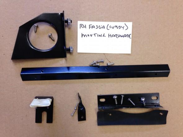
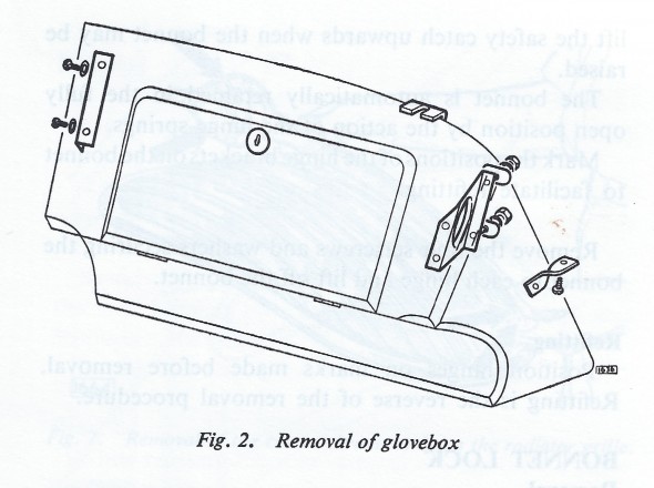
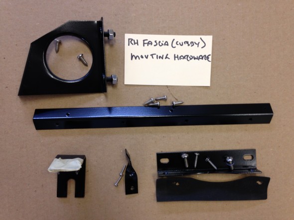
The glove box is mounted to the RH Wood Facia Board Assembly with the following components:

Cubby Box Components and Fasteners

Cubby Box Components and Fasteners

Bumpers

Bumpers

Front Bumper

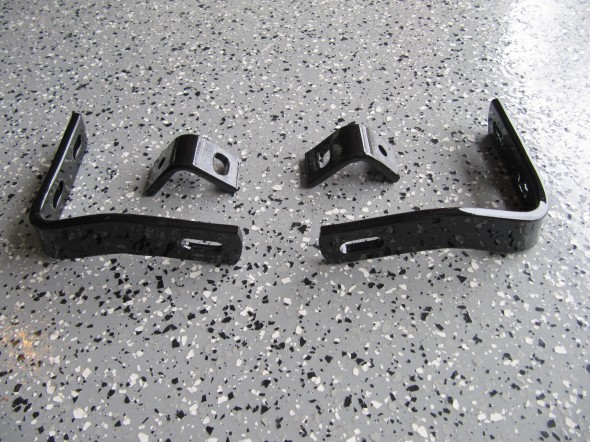
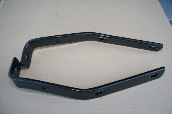
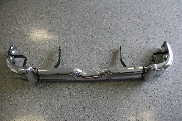
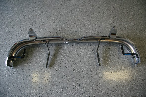
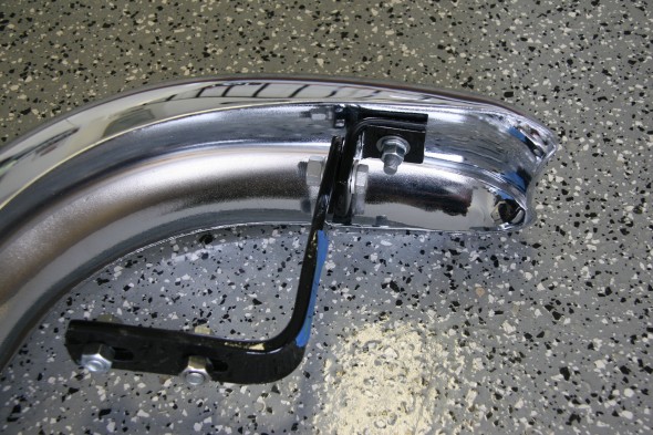
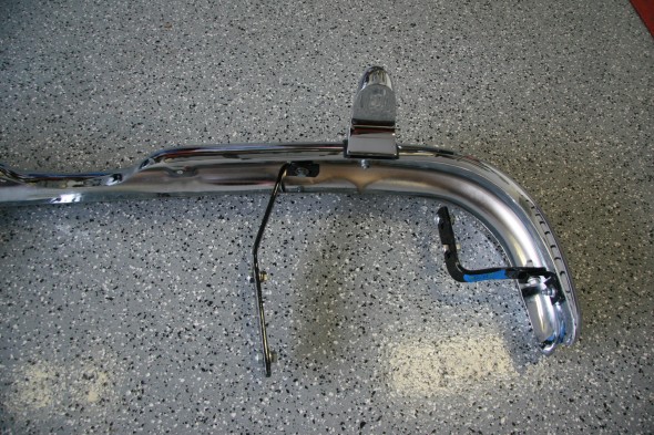
The front bumper is secured to the frame with two inner and two outer brackets and two angle brackets at the ends of the bumper. I media blasted these brackets and painted them with POR-15.

Outer Bumper Brackets with Angle Brackets

Outer Bumper Brackets with Angle Brackets

Front Bumper to Body Inner Brackets

Front Bumper to Body Inner Brackets

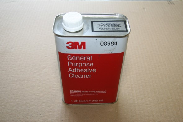
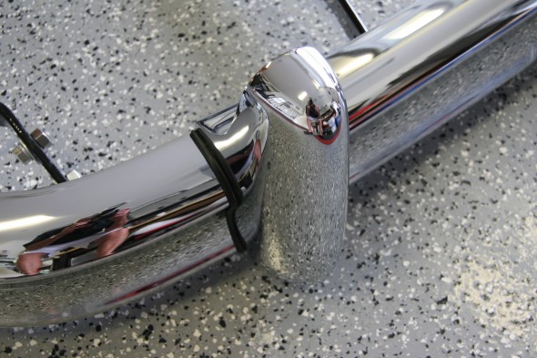
The bumpers were straightened and chromed. The over riders had some small dents. They were repaired and chromed as well. I painted the back side of the over riders with silver POR-15 rust treatment/paint. The overriders were mounted to the bumper with a special 3/8″- 16 round head bolt that fits through a rectangular opening in the over rider bracket and is secured with a spire nut.  I used new fasteners. Each over rider had a rubber beading seal one each vertical side. These were glued to the over rider with 3M black trim adhesive and then the over rider was bolted to the bumper. 3M Adhesive Cleaner was used to remove excessive black adhesive from the seals.

Front and Rear Over Riders with POR15 PaintFront and Rear Over Riders with POR15 Paint

3M Adhesive Remover

3M Adhesive Remover

Front Bumper with Over Rider and Rubber Seals

Front Bumper with Over Rider and Rubber Seals

I then assembled the front bumper mounting brackets to the bumper. All new bolts, and washers were used:

Front Bumper with all Mounting Brackets and Hardware

Front Bumper with all Mounting Brackets and Hardware

Front Bumper with all Mounting Brackets and Hardware

Front Bumper with all Mounting Brackets and Hardware

Side Mounting Brackets

Side Mounting Brackets

RH side Mounting Brackets

RH side Mounting Brackets

Rear Bumper and Mounts

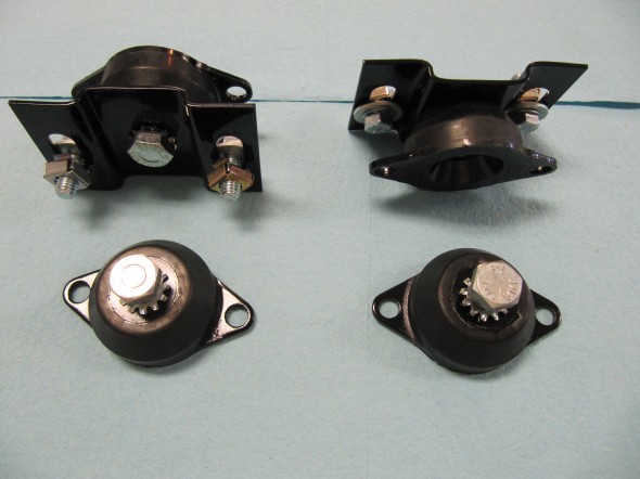
I ordered two new brackets, for outer mounting of rear bumper with new fasteners and four rubber bumper mounts. These came with exposed unpainted metal so I primed and painted them to avoid rust in the future.

Rear Bumper Mounts

Rear Bumper Mounts


Rear Over Rider Rubber Beading

Rear Over Rider Rubber Beading

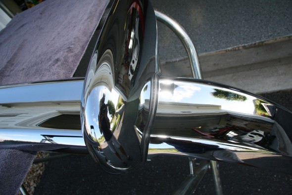
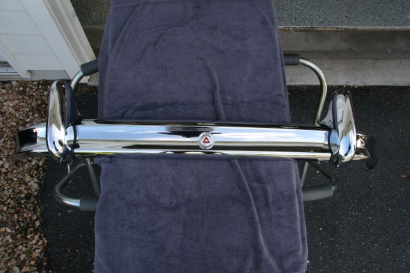
Rear Bumper with Over Riders and Rubber Beading Installed

Rear Bumper with Over Riders and Rubber Beading Installed

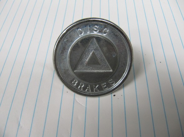
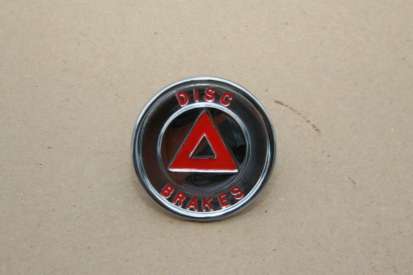
Rear Bumper Disc Brake Emblem

A round emblem is located in the center of the rear bumper signifying the four wheel disc brakes which was quite unusual at the time. I had the emblem rechromed and I painted the Triangle and the letters red as was original.

Rear Bumper Disc Brake Emblem

Rear Bumper Disc Brake Emblem

Painted Disc Brake Emblem for Rear Bumper

Painted Disc Brake Emblem for Rear Bumper

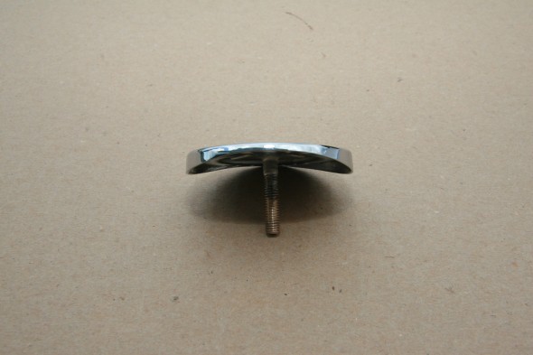
The Emblem is curved to fit the curvature of the rear bumper and is mounted with a flat and shake proof washer and nut:

Disc Brake Emblem for Rear Bumper

Disc Brake Emblem for Rear Bumper

Trial Fitting Rear Bumper

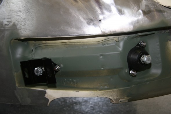
I cleaned the surfaces around the rear bumper mounts, painted the area with primer and installed the bumper mounts so that the bumper could be checked for fit and alignment. This would typically be done BEFORE chroming but circumstances prevented the normal process from occurring. All new bumper mounts and fasteners were used.

LH Rear Bumper Mounts


Radiator Grille

Radiator Grille

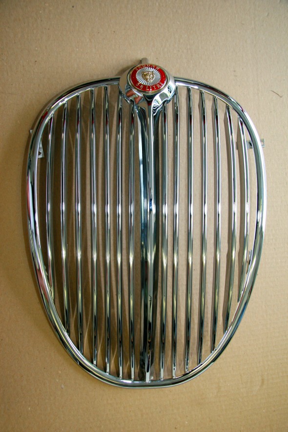
The Jaguar grille along with the bonnet-mounted Leaper is iconic. The two symbolize the visual image of Jaguar.

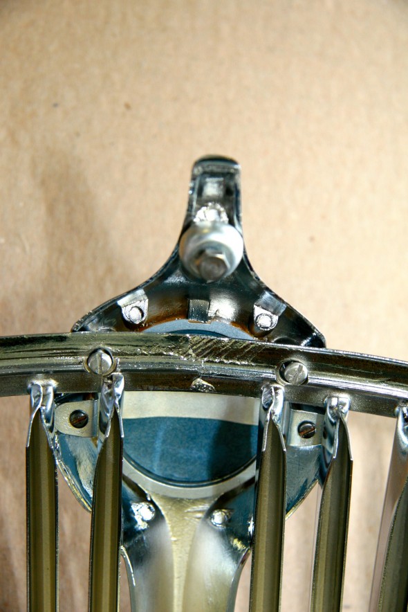
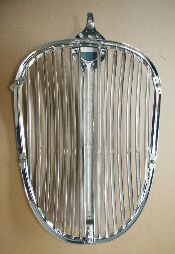
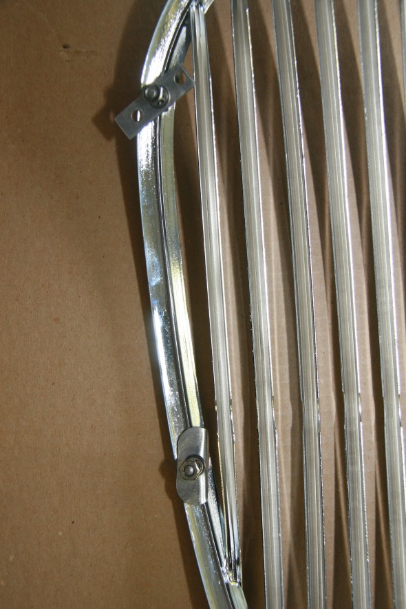
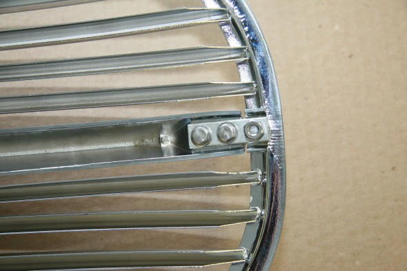
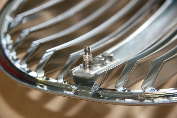
I had my grille and center vane rechromed. The stud on the lower mount broke when I disassembled the car. The fix for that problem is described below. I also have a few questions about the washers on the studs used to mount the grille to the front of the car. I am not sure if they are located in their original positions or not. I will do a bit more research before installing. A cup washer is used for the top center mounting. Two folded oval washers are used on the upper side studs and rectangular “strip washers” with mounting holes are used for the lower two side studs and the lower center stud.

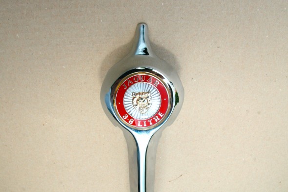
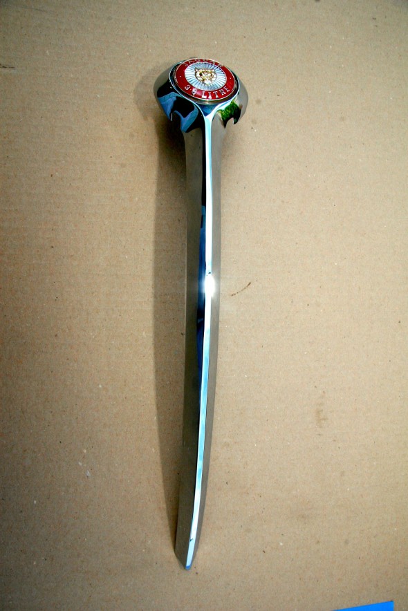
Otherwise, the assembly came out quite nicely. A new grille badge was installed in the center vane. The original spring clip and screws were used to mount the badge and then to secure the center vane to the grille. The images below show the assembly.

Radiator Grille Badge Installed

Radiator Grille Badge Installed

Radiator Grille Rear Side with Center Vane Mounting Hardware

Radiator Grille Rear Side with Center Vane Mounting Hardware

Radiator Grille Center Vane with Badge

Radiator Grille Center Vane with Badge

Radiator Grill Assembled

Radiator Grill Assembled

Radiator Grille Rear Side with Mounting Hardware

Radiator Grille Rear Side with Mounting Hardware

Radiator Grille Rear Side with Mounting Hardware

Radiator Grille Rear Side with Mounting Hardware

Radiator Grille Rear Side with Mounting Hardware

Radiator Grille Rear Side with Mounting Hardware

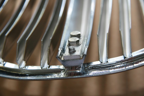
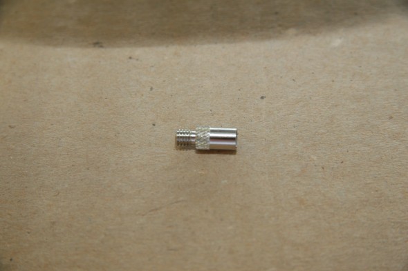
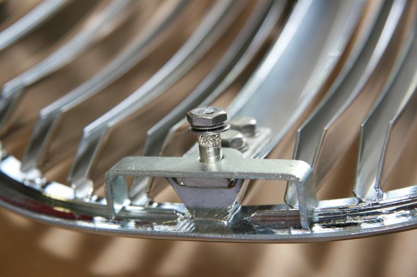
As mentioned previously, the center stud at the bottom of the grille broke when I tried to remove the nut. I think this is not uncommon! I happened upon a post to Jag-Lovers that provided the answer to this problem. Tony Coles purchased some throwing dart flight extenders. They are called “add a gram” on the U.K. Ebay. They come in brass or nickel plated steel. One end is female, the other male. Amazingly, they have 2BA threads on both ends, the same as the grille studs. I contacted Matt at [email protected] and he posted the extenders to me right away.

Fortunately, I had enough stud remaining on the grille that I was able to just clean up the threads a little, add some anti-seize for the future and then screw on the extender with the help of some vice grips. While a bit fatter than the original stud, it still fits through the lower fixing plate and the length is perfect. Thank you Tony!

Broken Lower Grille Mounting Stud

Broken Lower Grille Mounting Stud

Dart weight - Flight Extender

Dart weight – Flight Extender

Dart Weight as Stud Extender on Grille

Dart Weight as Stud Extender on Grille

Dart Weight as Stud Extender on Grille with Lower Radiator Grille Fixing Plate

Dart Weight as Stud Extender on Grille with Lower Radiator Grille Fixing Plate

Engine Rebuild

Clean-up Before Rebuild

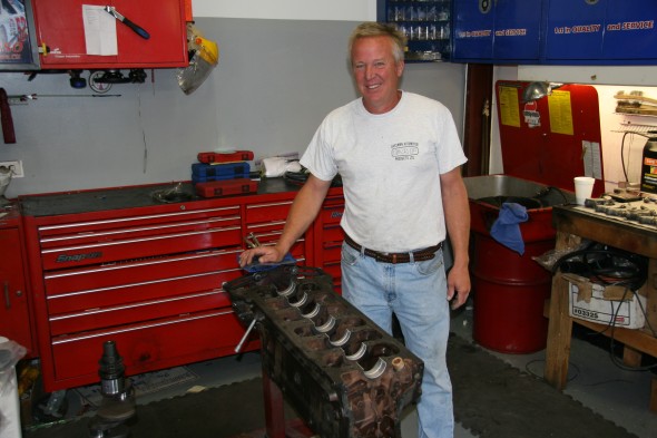
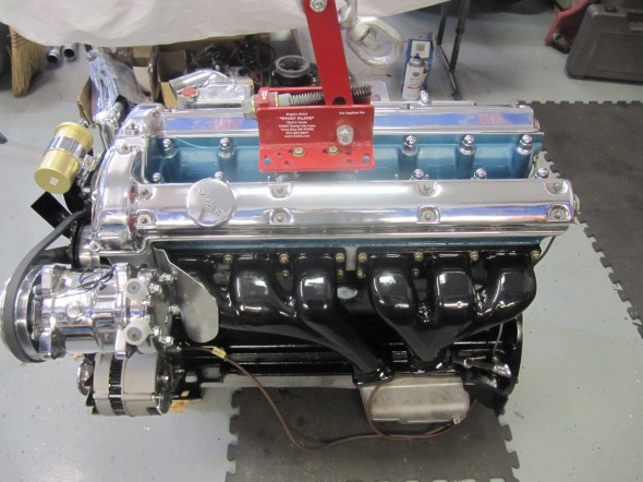
I had thought about outsourcing the machine block cleaning and machine work and then rebuilding the engine myself, but thought better of it given time limitations and decided to go ahead and give the complete engine to Mike Gassman at Gassman Automotive http://www.gassmanautomotive.com for a soup to nuts rebuild. Mike and his team had done XK motors before and are experienced with the motor, ignition, fuel system and etc.

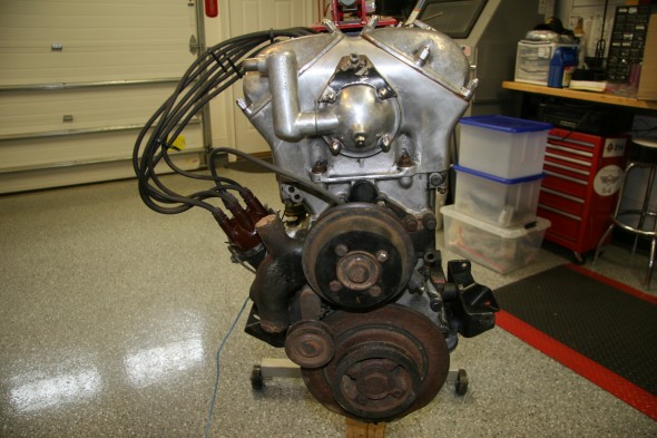
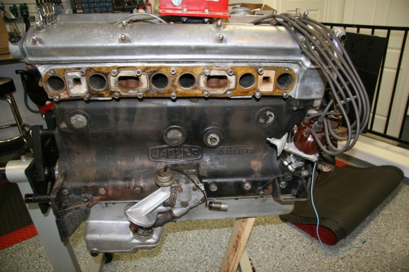
I spent a few days cleaning the block and head to remove as much grease and grime as possible before turning everything over to Mike.

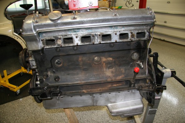
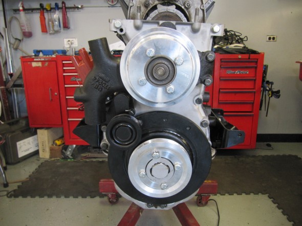
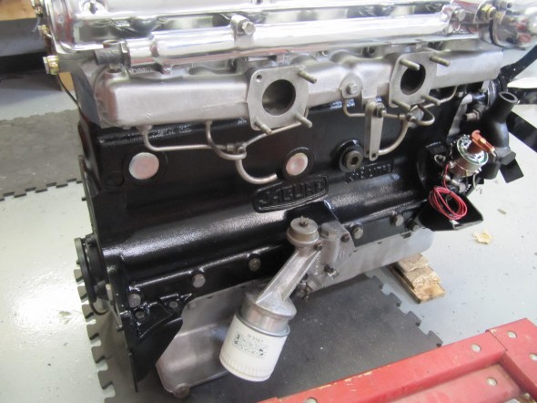
Front of Cleaned Engine Before Rebuild

Front of Cleaned Engine Before Rebuild

RH Side of Engine

LH Side Engine

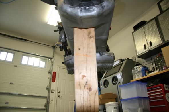
Underside of Engine

Rebuild Engine

Machine Work:

  • Resurface Head
  • Valve Job
  • Install Guides
  • Pressure Test
  • Resurface and weld Exhaust Manifold Cracks
  • Drill for Oversize Lifters
  • Drill for Hold Downs
  • R&R Pistons
  • R&R Bushing Under Over
  • Recondition Big End
  • Grind and Polish Crankshaft
  • Magna-Flux Crankshaft
  • R&R Crank Plugs
  • Rebore and Hone Block
  • Pins
  • Replace Core Plugs
  • Balance Pressure Plate, Cylinder Block
  • Resurface Flywheel
  • Magna-Flux Block
  • Resurface Cylinder Head
  • Polishing Two Valve Covers, Two Carbs Dashpots, Intake Manifold, Oil Cap, Cover and Water Neck

Parts:

Where possible used components in good shape were used in the rebuild; however, in many instances new parts were required to replace worn or broken bits. The original compression for the 3.8 MK2 engine was 9:1; however, primarily because of the lower octane rating of fuel today and due to the way I plan to use this car, I decided to use 8:1 compression Mahle pistons in my rebuild. This is not a complete list and it is in no particular order, but new parts ordered included the following:

  • Cam bearing Set
  • Engine chrome hardware
  • Oil Filter
  • Spin-On Oil Filter Kit
  • Payen Brand Head Set
  • Cylinder Head Studs
  • Seal Kit
  • Lock Tab Kit
  • Thrust Washer Set
  • Piston set
  • Tri-metal Connecting Rod Bearing Set
  • Tri-metal Main Bearing set
  • Core Plug Set
  • Pilot Bushing
  • Clutch Kit
  • Water Pump
  • Timing Chain, Guide and Tensioner kit
  • Lower Gasket Set
  • Tappet Hold Down Kit
  • Tappet Guide
  • Valve Spring Set
  • Oil Pump
  • Oil Pump Adapter
  • Bronze Valve Guide Set
  • Intake Valves
  • Exhaust Valves
  • Oversize Tappets
  • 10W30 Break in Oil with Zinc Additive
  • 15W50 Oil with Zinc
  • Engine and Bearing Assembly Lubricant
  • Sealants/Sealers/Cam Lube
  • Gloss Black paint
  • Metallic Blue Spray Paint for the Cylinder Head
  • Flamethrower Coil
  • Chrome Coil Bracket
  • Flamethrower Ignition Leads
  • Spark Plugs
  • 123 Distributor
  • Brass Nuts
  • Thermostat
  • S.U. Throttle Shaft 1 3/4″ Butterflies
  • S.U. 1 3/4″ Butterflies
  • 5/16 22 BSF Banjo Bolt HD Starting Carb
  • 3.8 MK2 SM/1402 Carb Kits
  • Drive Belt
  • Hoses to Radiator
  • Radiator Hose Clamps
  • Heater Hose
  • Heater Hose Clamps
  • Gear Reduction Starter
  • Engine Ground Strap
  • Oil Pressure Sender
  • Oil Quick Drain Valve
  • Blast, Anneal and Porcelain Coat Exhaust Manifolds
  • Carb Banjo Bolts and Washers
  • Alternator and Mounting Bracket

Rear Main Crankshaft Seal

I did some research on the replacement of the rear main crankshaft seal. A number of the usual vendors sell modern upgrades for this seal to help prevent oil leakage. The apparent most popular upgrade kit does require some machining of the crank.

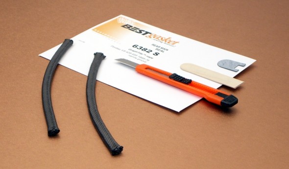
After checking with those on the saloon-lovers forum and a few other MK2 owners, the consensus seemed to be to stay away from the upgrade kits. However, Peter Wise aka “Old Goat” [email protected] recommended a GraphTite seal made by BEST Gaskets as a modern material upgrade to the original rope seal. The kit is available from EGGE Machine http://www.egge.com  part number: 6382S and it is for a Pontiac 1968-76 8 cylinder 428-455. It is a direct replacement for the rope and does not require any machine work. I cannot explain why the Pontiac V-8 seal works in the MK2 3.8 but Pete claims that it works quite well. I have ordered the kit and Mike and his team installed the seal upon rebuild. The seal kit included an installation tool for $17.39!

GraphTite Rear Main Seal

GraphTite Rear Main Seal

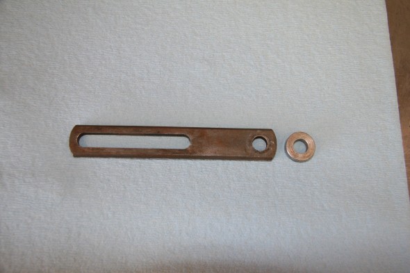
Dynamo Mounting Bracket and Spacer

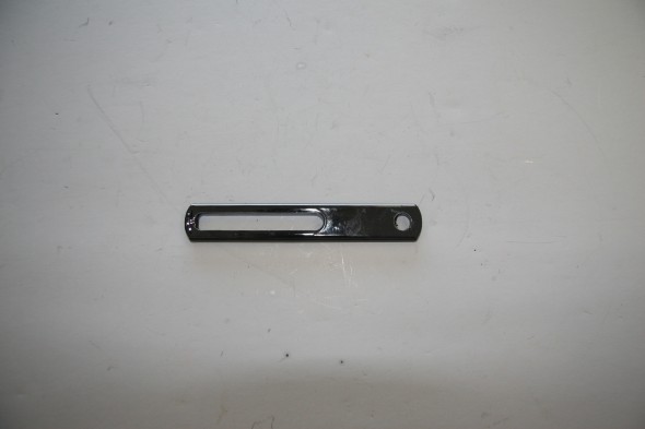
I probably will not use the dynamo bracket with my alternator, in favor of a turnbuckle brace, but I cleaned it up and painted it  – just in case.

Dynamo Adjustment Bracket


Dynamo Bracket

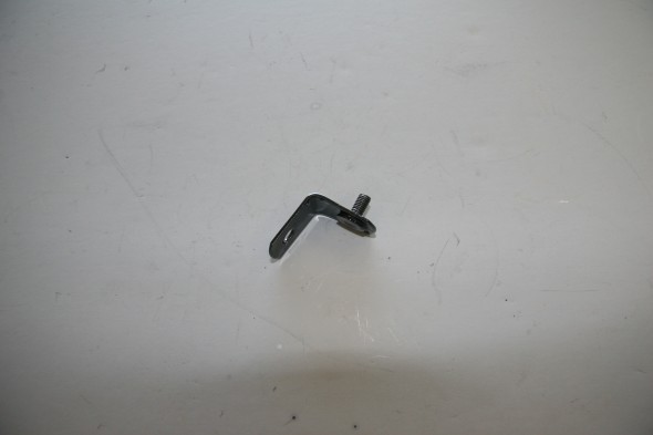
Coil Bracket Extension

Coil Mounting Bracket Extension

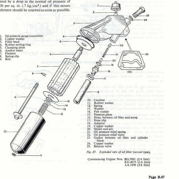
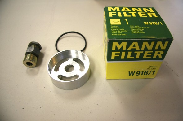
Spin-on Oil Filter Kit

Oil Filter Assembly

Oil Filter Assembly

As seen in the image above, the original oil filter is a full flow type and has a renewable felt or paper element. Modern spin-on alternatives are available and I installed the kit provided by SNG Barratt. Purists may object, but most who have installed the spin-on arrangement report success and it is certainly much easier to change.

Spin-on Oil Filter Instructions

SNG Barratt Spin On Oil Filter Kit

SNG Barratt Spin On Oil Filter Kit

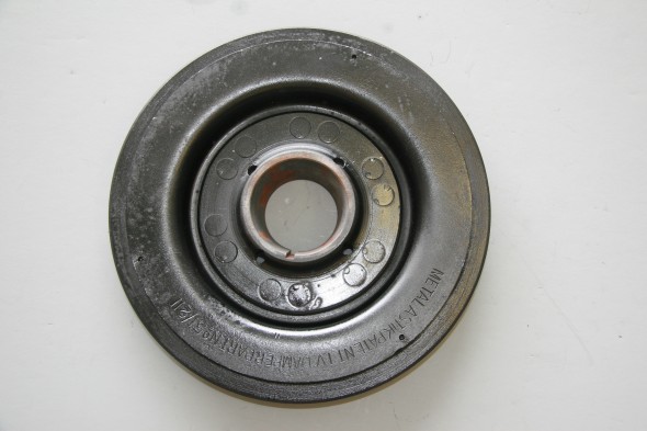
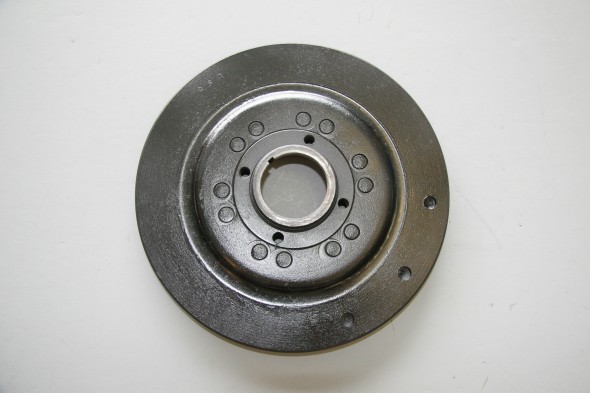
Harmonic Balancer

I decided to have the harmonic balancer rebuilt by Dale Manufacturing http://hbrepair.com/harmonicbalancer_018.htm in Salem, Oregon rather than purchase a new one. The rebuild was under $150 and the final product looked pretty good.

Harmonic Balancer

Harmonic Balancer

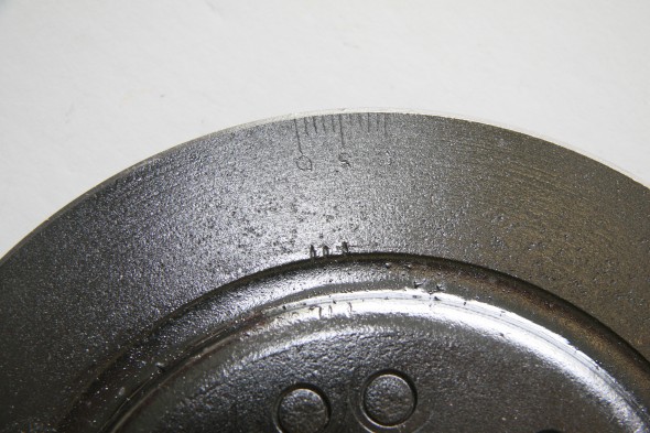
Timing Marks

Oil Sump Dipstick

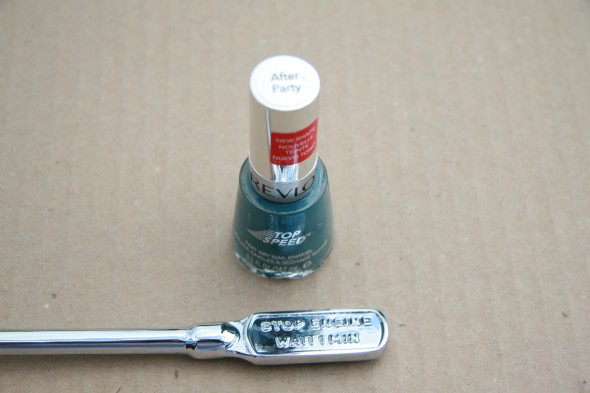
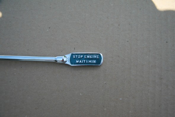
Got the dipstick back from the plater. I vaguely recalled that the background on the handle was a somewhat unusual blue color. Someone on the Forum indicated that Revlon’s After Party nail polish was the perfect color, so I ordered some and painted the handle:

Revlon's After Party Nail Polish

Revlon’s After Party Nail Polish


Revlon's After Party Nail Polish after Application

Revlon’s After Party Nail Polish after Application

Oil Drain Plug

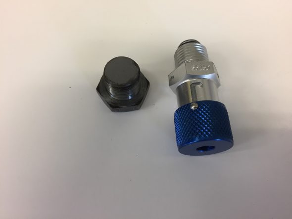
I ordered an EZ Oil Drain Valve for XK Engines from Cool Cat Express just to make the oil drain process a little easier. As their advertisement says; “This all aluminum drain valve mounts permanently in place of your drain plug. A simple twist of the wrist will open and close it. No more stripped threads, no more lost plugs. One piece aircraft quality 6061 aluminum and 302 stainless steel. Aluminum has clear anodized finish for long, corrosion free life. Seals are replaceable. Nothing to break, nothing to lose: saves labor, saves your oil pan, save aggravation. The perfect companion for our spin on conversion kits! Fits all Jaguar oil pans with 5/8″-18 thread. This includes ALL XK motors, and many V12’s.”

This is a photo of the Valve and the plug it replaces:

Cool Cat Express Oil Drain Plug

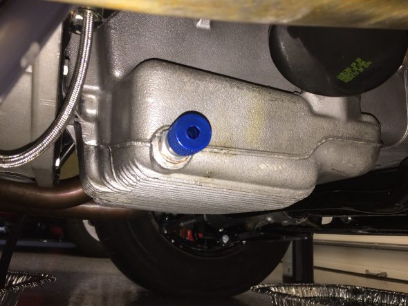
Here is a photo of the new valve installed:

Cool Cat Express Oil Drain Valve Installed

Engine Rebuild Process

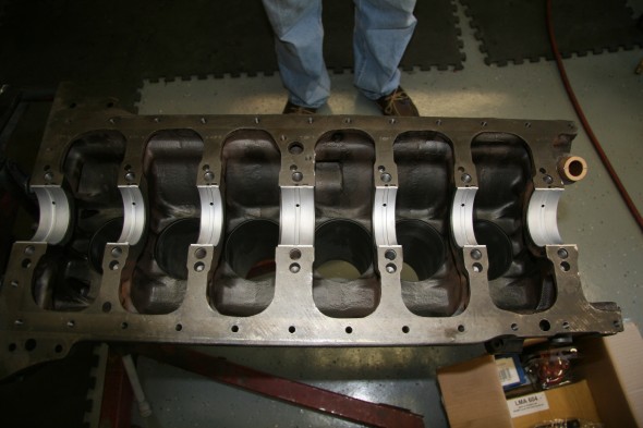
Mike Gassman Installing bearings

Mike Gassman Installing Bearings

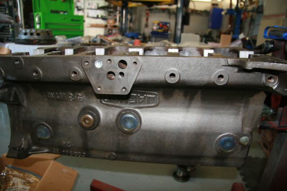
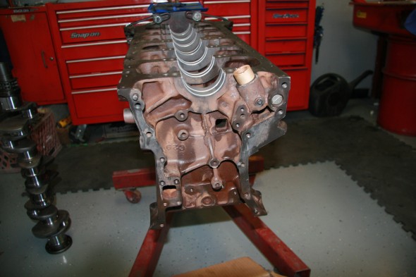
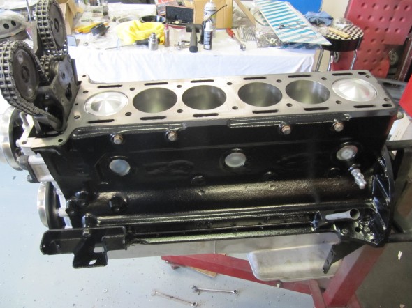
Engine Block

Engine Block

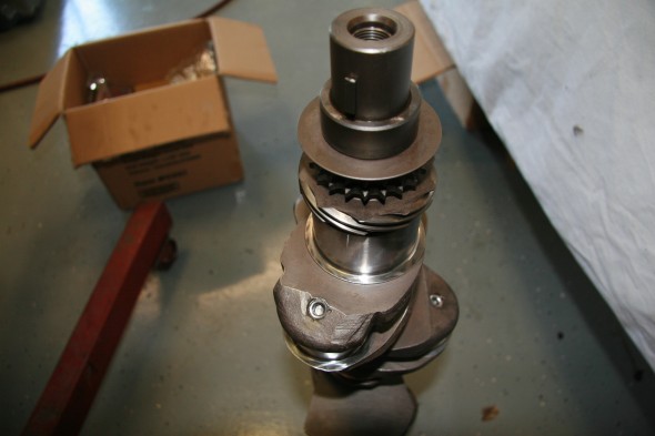
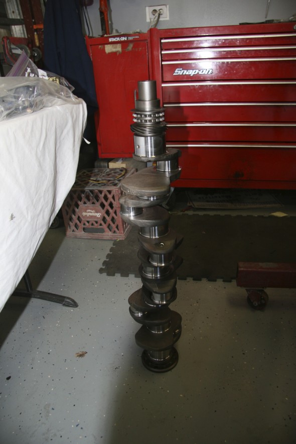
Crankshaft

Crankshaft

New Main Bearings

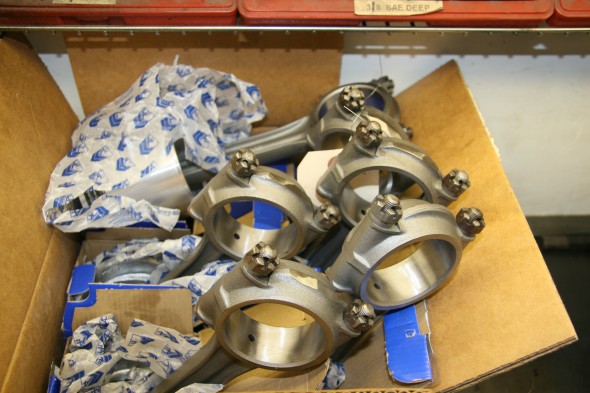
Connecting Rods

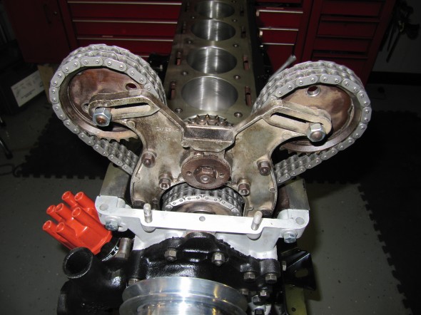
Timing Gear Chain

Pistons & Timing Gear

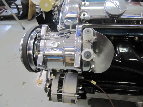
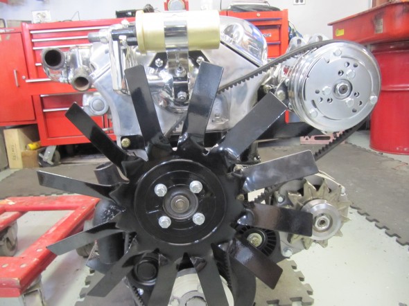
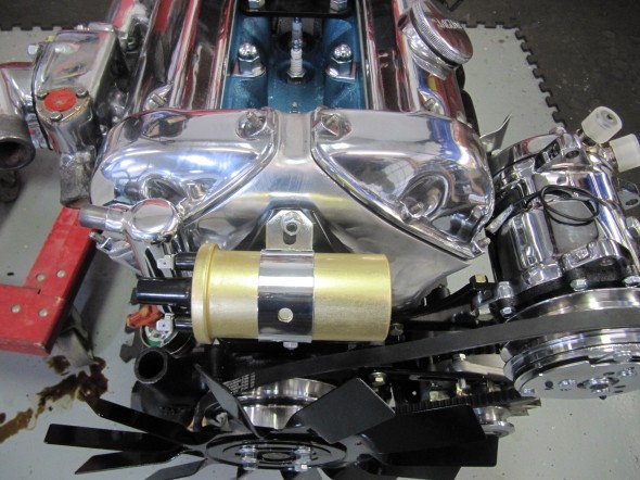
RetroAir Aluminum Pulleys


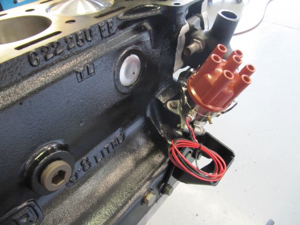
123 Distributor

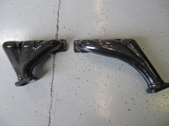
New Porcelain Exhaust

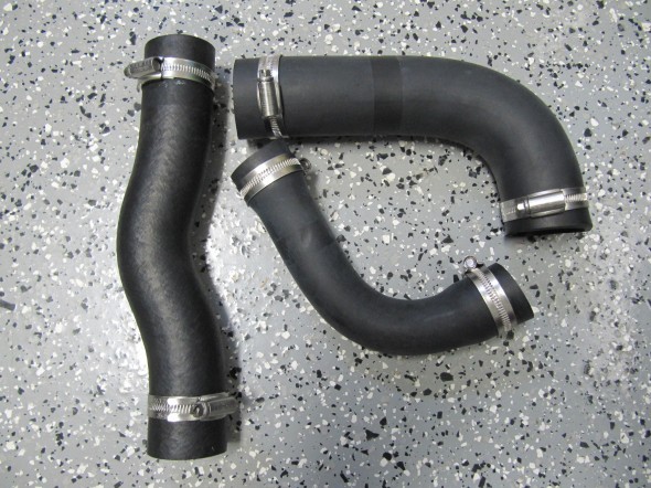
Primary Coolant Hoses

Engineering Art

Compressor & Shield

New Belt Routing

Distributor

Spin-on Filter

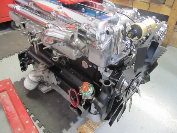
Front View

Engine Run-In

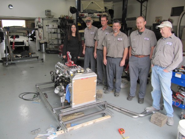
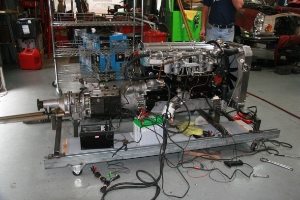
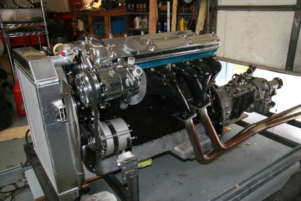
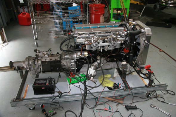
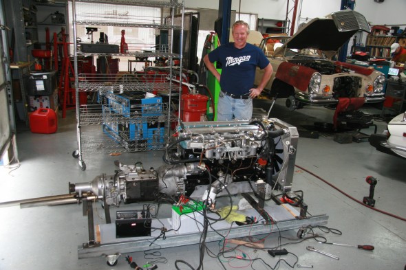
After Mike and his staff got the engine together they made a test stand so that we could do preliminary adjustments and make sure we were leak free. I am trying Evans Waterless Coolant in this engine and it was used in the testing.

All of the attention to balancing really paid off as the engine runs very smoothly with very little vibration. Everything checked out beautifully.

Thanks to Mike for a beautiful engine and a beautiful job. I recommend him to others without reservation.

The Gassman Team

The Gassman Team

Engine Testing

Engine Testing

Engine Testing

Maestro Mike

Maestro Mike


Body Metal work

Body Metal Work

I knew when I purchased my MK2 that it had a few areas that would require rust repair, although for a fifty year old British car it was remarkably free of serious rust problems. Immediately recognizable was battery acid/rust damage to the firewall, and the plenum was swiss cheese. I expect that the plenum rust problem was caused by a clogged drain due to mice nests in the plenum and the heater!

Fortunately, a Jaguar MK2 acquaintance, Robert Seligman, recommended that I contact John Stefanik about making the metal work repairs. Bob was very pleased with work John had done for him and I felt fortunate to have come upon such a skilled artisan. Not only did John perform brilliant work, he did everything I asked within two and one-half weeks from the time that I delivered my MK2 to him.

In addition to making the needed repairs, John also worked on fitting the metal Coombs wheel covers that I had purchased to replace the original spats. This was no easy task requiring significant heating/cooling, bending and shaping.

I was fortunate to find a used (and rust free) replacement plenum and a patch panel for the firewall that John expertly installed in my car.


zz

Dash

Dash Components

Air Distributor Box

Details on the box which sits below the dash can be found under the Heater post: https://valvechatter.com/?cat=103

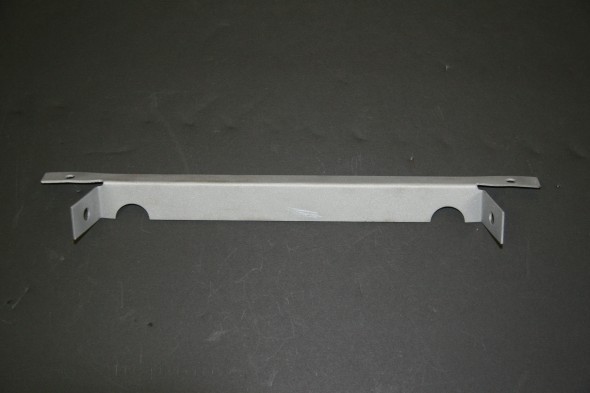
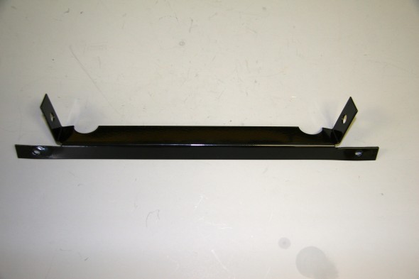
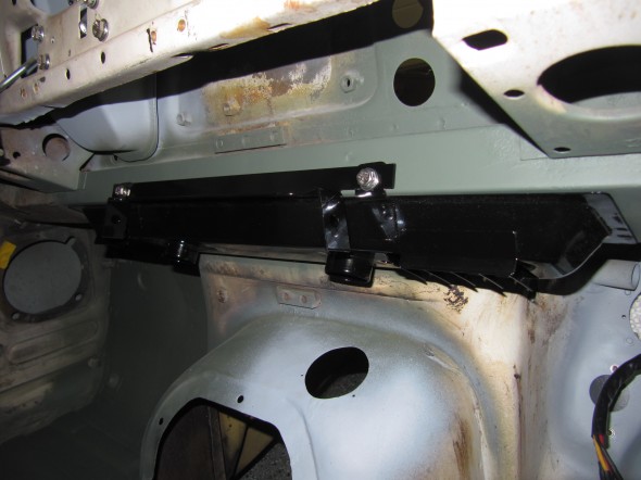
Mounting Bracket for Radio Control Panel

This bracket shares the mounting bolts with the air distributor box, and mounts behind and above it.

Mounting Bracket for Radio Control Panel

Mounting Bracket for Radio Control Panel

Powder Coated Mounting Bracket for Radio Control Panel

Powder Coated Mounting Bracket for Radio Control Panel

Air Distributor Box Installed

Air Distributor Box Installed

Instrument Panel Assembly

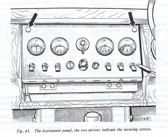
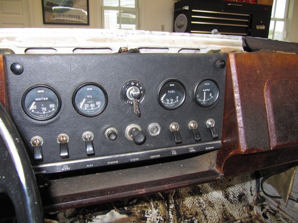
While the speedometer and tachometer are placed directly in front of the driver in the MK2, the rest of the gauges and most of the switches are located in a central panel in the dash referred to as the Instrument Panel Assembly. The panel is mounted with two thumb screws at the top corners of the panel that when released permits the panel to swing out on hinges.

Information regarding the individual gauges, instruments, and switches may be found under the “Gauges, Instruments and Switches” post.

Instrument Assembly Panel

Instrument Assembly Panel

Newspaper Tray

The Newspaper Tray sits immediately below the gauge panel in the center of the dash.

Newspaper Tray

Newspaper Tray

It is secured with two #10-32 nylock nuts and two rubber washers on the mounting studs.

Newspaper Tray

Newspaper Tray

Newspaper Tray

Newspaper Tray

Newspaper Tray

Newspaper Tray

The newspaper tray has a grey flocking on the interior of the envelope. At this time I am not sure how I will replicate the flocking, but I am sure that I will figure out something. I media blasted the tray to prepare it for powder coating.

Newspaper Tray

Newspaper Tray

Newspaper Tray

Newspaper Tray

Right and Left Fascia Board Assemblies

For the purpose of testing my electrical system, gauges and instruments, I installed my yet to be refinished dash fascia boards. The driver’s side fascia board houses the Handbrake “ON” Position and Brake Fluid Container Level Warning Lamp,  the speedometer and the tachometer with internal clock. The speedometer includes warning lamps for high beams, low fuel and ignition charging. The passenger side fascia board houses

the “Cubby” glove box that incorporates a light that illuminates when the door is opened.

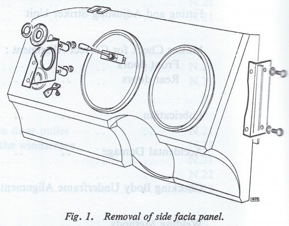
As the Service Manual suggests, fitting and removing the driver’s side Fascia Board is made easier (though not necessary) by dropping the steering column to the seat. The central instrument panel was already removed from the car.

Since this is not my final installation I did not install the small twisted (steady) brackets nor the top brackets for the mounting of the screen rail dash top.

Driver's side fascia board

Driver’s side fascia board

Passenger side fascia board

Passenger side fascia board

I did install the LH and RH mounting brackets to the wooden fascia as seen in the images above. The brackets were all cleaned, bead blasted and repainted before mounting to the fascia boards.

Fascia Board Refurbished mounting hardware

Fascia Board Refurbished mounting hardware

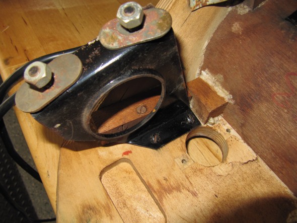
While I did not get a photograph of the wood when I reinstalled the renewed brackets one can see in this image that outside brackets for both fascia boards have studs that go through holes in the car’s body bracing and are then secured with “special” oval washers, split washers and nuts.

Driver's side fascia board outside mounting bracket

Driver’s side fascia board outside mounting bracket

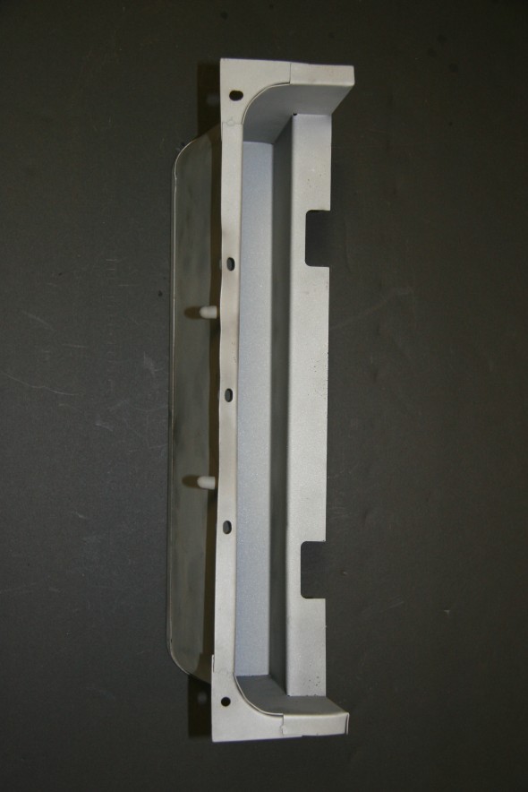
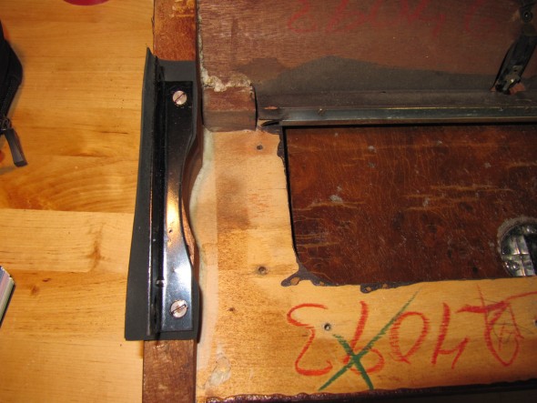
The inside brackets for both fascia boards have rubber seals that I assume are to block light that might escape from behind the instrument panel. Two #10 – 32 x 1/2″ machine screws mount through the inside brackets into the car’s body.

Passenger side fascia board internal mounting bracket

Passenger side fascia board internal mounting bracket


Cubby Box Door Hinge

The Cubby Box Door Hinge is a chrome sliding hinge, being in excellent condition, I simply cleaned and polished the hinge. It is attached to the Cubby Box with four chrome slotted wood screws.

Rear Axle

Rear Axle

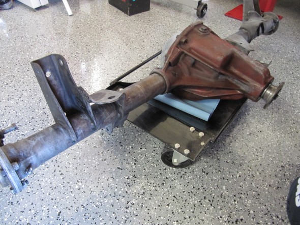
All of the MK2s are fitted with a 4.HA Salisbury axle. The rear axle assembly is a semi-floating type with shim adjustment for all bearings and meshing of the hypoid drive gear and pinion matched assembly. The axle shafts are splined at the inner ends, which engage splines in the differential side gears, while the outer ends have tapers and keys to fit the rear wheel hubs. The hubs are supported by taper roller bearings pressed on the axle shafts and located in the end of the axle tubes. A cover on the rear of the gear carrier allows inspection without dismantling the axle.

Additional information about the axle installation and its related components in the rear suspension can be found in the “Rear Suspension” post at https://valvechatter.com/?p=3826.

Refurbishment

There is a big component stored in the garage that I have had trouble ignoring, but I have been putting off cleaning and refurbishing the rear axle for sometime. Perhaps it was Thanksgiving or the approaching holiday season, I don’t know, but I got motivated to start work on the axle. The axle images are sans the rear hubs. A description of the removal of the rear hubs is available in the disassembly section of posts,  Entry 39 .

For starters, I took advantage of having the lift in the garage and used it to  make it easy to access the axle for cleaning.
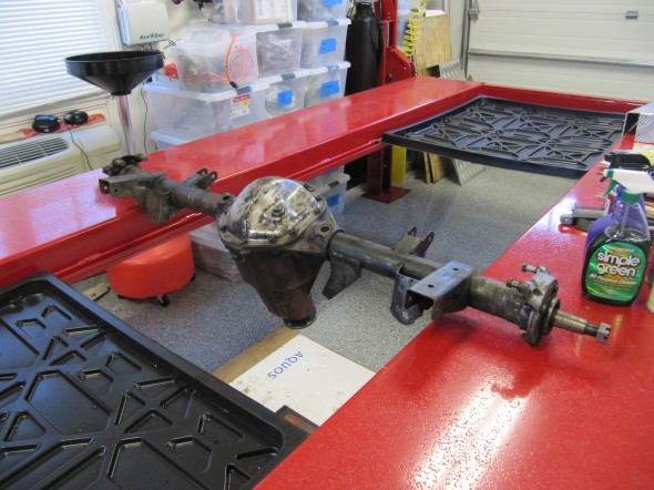
Rear Axle on Lift for Cleaning

Rear Axle on Lift for Cleaning

It was really just a matter of using the putty knife, cleanser, throttle cleaner, a wire brush and rags to remove the dirt and grime. After getting things as clean as possible I then used POR 15’s painting prep product called Prep & Ready. Prep & Ready is used to neutralize any rust and etch and clean bare metal to allow better adhesion of POR-15. Directions call for soaking the metal and keeping it wet for approximately fifteen minutes and then washing it away with water and then dry.
Prep & Ready
Prep & Ready

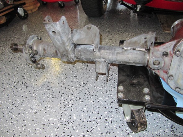
Axle Degreased

Axle Degreased
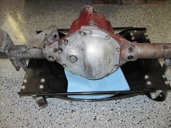
Axle Degreased

Axle Degreased

Axle Degreased

Axle Degreased with Prep & Ready

The differential casing on my axle had very little (if any) black paint and so I wondered if it should actually be painted red. I did a little research and this is what Rob Reilly contributed on the Saloon-Lovers email list:

In the build process, after the cast iron center pumpkin was shaken out of the sand mold and shot blasted, it was dunked in Glyptol, usually orange or red though Glyptol comes in other colors. This is to seal in the microscopic sand particles remaining in the boundary layer at the surface of the cast iron. Same as XK engine blocks and Moss gearbox main housings. It was very dry in the foundry and the Glyptol stuck very well. Then it went to the machine shop, where the machining work was done on it, which takes off the boundary layer. It is not necessary to repaint it on these machined surfaces. Then the axle tubes were pressed in and welded through plug holes in the casting. Then the parts were assembled into it. At this point it was very oily all over the outside of the diff. Then the whole thing was painted black without any primer, but they did not clean it very well first, if at all.

So after a few years the black flaked off, revealing the orange or red. If you look carefully as I did on mine, you may see black on the axle tube plug welds, because the welding burned away the red/orange and the oil, so the black stuck better there. Mine had small flecks of black remaining on the outside of the diff. I also saw only black on the outside of the rear cover, and nothing at all on the inside of this cover. It is not necessary to restore the Glyptol on the outside of the diff. It is only important on the inside.

Thanks to Rob, for providing the history on why the differential casing on my car was red/orange – they all were!

Brake Caliper Adaptor Plates

I then removed the LH and RH brake caliper adaptor plates. Each was secured to the axle with four 3/8″ – 24 x hex head bolts and nylock nuts, bolt heads to the outside. Each caliper was mounted to the adaptor plate with two 7/16″ -20 x 1 1/4″ hex head drilled bolts with split washers and safety wire. Shims were found on three of the caliper mounting bolts. They were noted for reassembly.
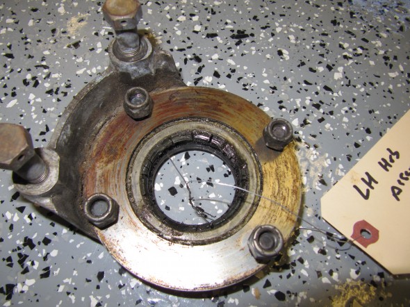
LH Adaptor Plate
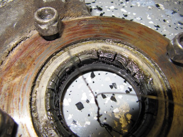
LH Adaptor Plate

LH Adaptor Plate

LH Adaptor Plate

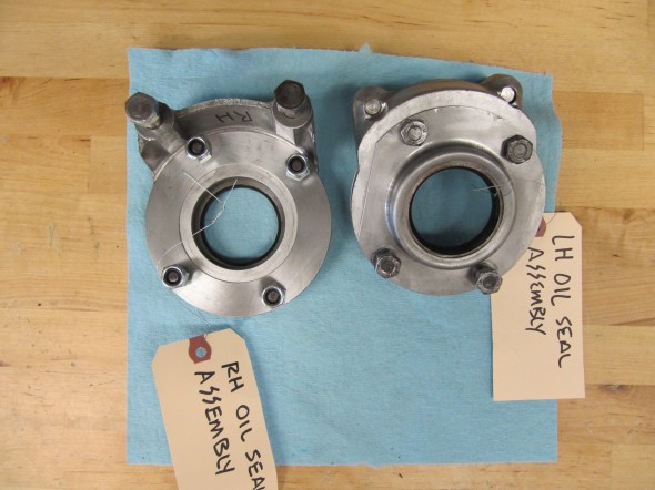
Oil Seal Assembly

The next task was to remove the LH and RH oil seal assembly from the axle. The assembly consisted of: the oil seal on the end of the carrier tube axle shafts, the hub bearing adjusting shims, and a gasket. I was careful to record the number, location (LH or RH), and size of the shims, and I will replace the bearings and gasket later.
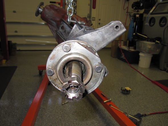
RH Oil Seal Assembly

RH Oil Seal Assembly

The image below shows the face of the timken bearing ( 14130-X-14276) 7HA-025).
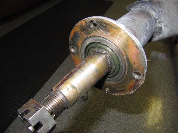
RH Axle Shaft with Bearing & Seal

RH Axle Shaft with Bearing & Seal

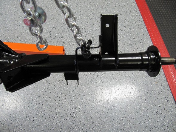
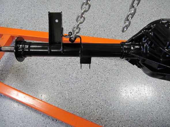
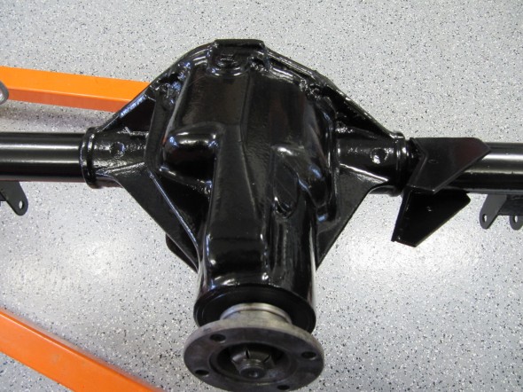
After cleaning up around the removed adaptor plates, I then painted the axle tubes and casing with two brushed coats of glossy black POR-15 followed by one sprayed coat of gloss Blackcoat which is a permanent overcoating developed as a non-porous finish that as advertised will not crack or chip. Unlike the POR-15 it is not harmed by exposure to sunlight.
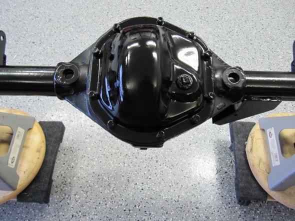
Rear Differential Carrier Cover
Rear Differential Carrier Cover

Rear Differential Bottom View

Rear Diff Bottom

Painted Axle

Painted Axle
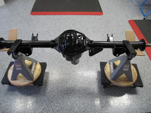
Painted Axle

Painted Axle


Newly Painted Rear Axle

Newly Painted Rear Axle

Rear Differential Identification Tags

Two stamped tags were located on the upper and lower mounting bolts for the carrier cover. One was stamped 49/13 which is the final drive gear ratio or 3.77. This ratio was the gear set fitted for overdrive equipped cars. I am told that the other which was stamped with “BP-L” signifies that the differential is a Powr-Lok  Limited Slip.
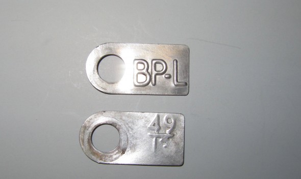
Differential ID Tags

Differential ID Tags

Bearings and Seals

When I purchased the MK2, I drove the car for five-six miles. I did not hear anything unusual from the rear end, and the differential does not appear to be leaking from the pinion. I will replace the axle shaft/hub bearings and seals and gaskets along with new hubs, but upon the advice of others, I am going to leave everything else alone for the time being. I have taken off the carrier cover and visually inspected the crown and pinion surfaces with no apparent wear problems.

Oil Seal Assemblies and Brake Caliper Adaptors

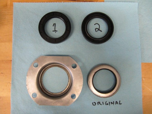
The final components of the ale to clean and reassemble were the LH and RH oil seal assemblies and brake caliper adaptors. The LH assembly had four shims (.o1″, .01″, .03″, and .03″) while the RH had only one shim (.03″). The assemblies were bolted to the axle ends with four 3/8″ -24 x 1 1/8″ hex head bolts and 3/8″ – 24 nylock nuts. Sandwiched between the oil seal assembly and the adaptor was a paper gasket. The original oil seal was a metal encased leather seal, while the new replacements are an improved rubber seal as shown in the images below.

The brake calipers were mounted to the adaptors with two 7/16″ -20 x 1 5/16″ drilled (for safety wire) hex head bolts with split washers. The RH adaptor had two .02″ shims on each bolt, while the LH side had no shims.
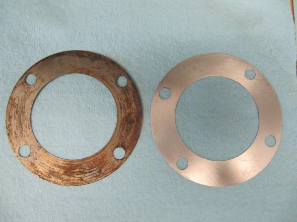
Shims
Shims

Oil Seals

Oil Seals

LH and RH Oil Seal Assemblies and Adaptors Cleaned
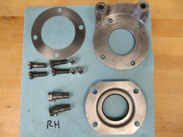
LH and RH Oil Seal Assemblies and Adaptors Cleaned

RH Oil Seal Assembly Components and Caliper Adaptor After

RH Oil Seal Assembly Components and Caliper Adaptor After

Installing the Axle and Springs

Based on comments of others, this is my plan for reinstalling the axle and springs into the car.

  1. Loosely mount the springs to the axle,
  2. Roll the axle under the car on the wheels and tires
  3. Lower the body to loosely attach the torsion rods
  4. Swing the springs up into the front mounts
  5. Raise the axle up into place
  6. Secure with the spring mount plate


zzz

Body Prep

Removing Grease, Grime and Rust

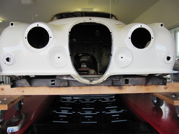
On the Jaguar project, I am trying to keep the cost down by doing much of the work myself rather than just handing the car off to a shop to restore. Unfortunately, that means removing years of grease and dirt without many of the tools that you might find in a professional shop. Actually, the grease and dirt aren’t so challenging, but the undercoating and tar-like substance used in the interior are an entirely different matter!

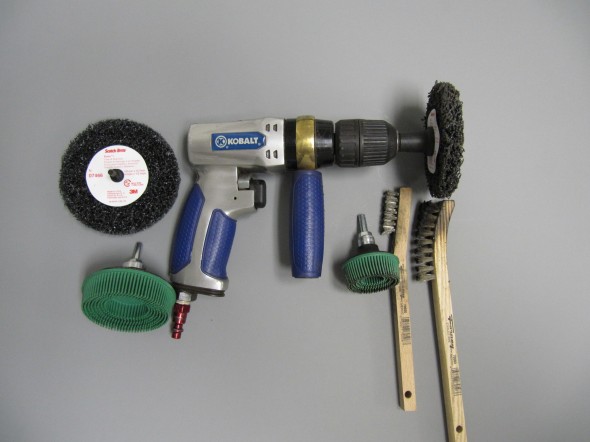
I first tackled the engine bay using Simple Green cleanser, a little carb cleaner, wire brushes, some 3M abrasive disks with compressed air, a face mask, and protective glasses.

Cleaning Tools

Cleaning Tools

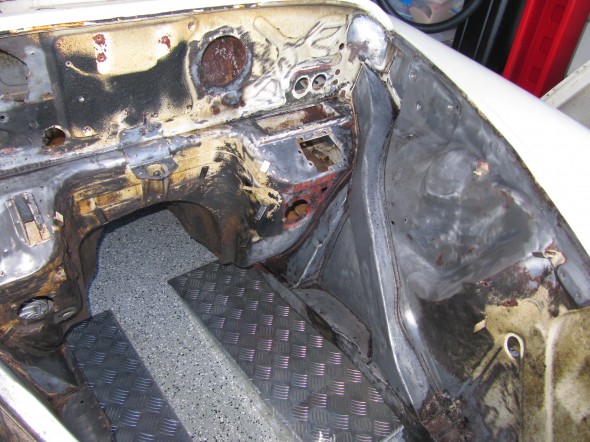
Cleaning the Engine Bay

Cleaning the Engine Bay

Cleaning the Engine Bay

Cleaning the Engine Bay

Cleaning the Engine Bay

Cleaning the Engine Bay


Once I finished the engine bay I sprayed a rust inhibitor on it and then I did take the body shell to my friend Jeremy Turner at Maple Hill Restoration who sand blasted the engine bay and sprayed it with a PPG self etching primer, called wash primer. The primer is DX1791, the activator is DX1792. Other than the upper RH section of the firewall that was rusted away from battery acid and a few holes in the ventilation distribution chamber (I don’t know the proper name) everything seemed very solid. I noted that the area in front of the radiator was apparently painted a flat or satin black and given the evidence of paint drips it was probably painted by brush.

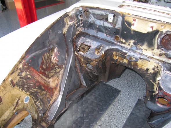
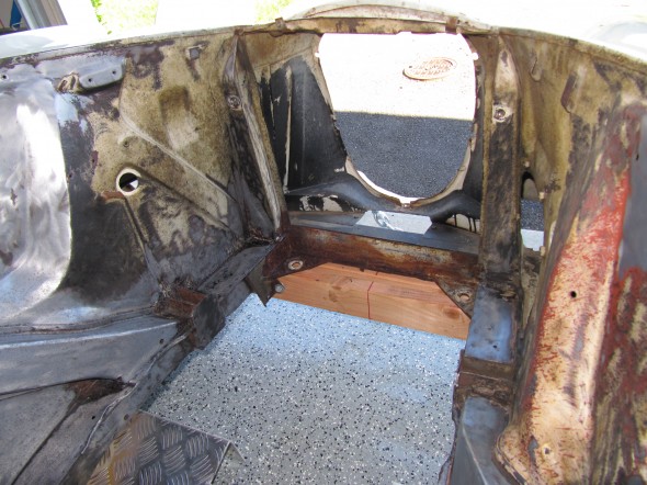
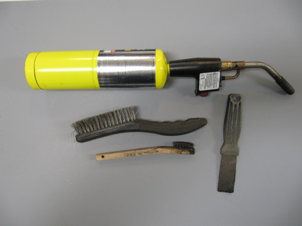
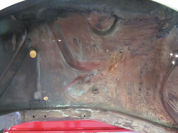
After getting the car back from Jeremy I moved on to the left wheel well and the LH front section of the frame. I tried some undercoating remover from Eastwood, but it didn’t work so well. I then resorted to the old standby – a hand held propane torch and a putty knife. While the process is slow it did produce good results and I discovered very little rust.

The Tools Required for Undercoating Removal

The Tools Required for Undercoating Removal

Front LH Wheel Well

Front LH Wheel Well

Front LH Wheel Well

Front LH Wheel Well

Front LH Wheel Well

Front LH Wheel Well

It is another day and time to work on cleaning up the RH front wheel well. Here are a few before and after shots following application of the propane torch, putty knife scraper, wire brush and elbow grease:

RH Wheel Well Before

RH Wheel Well Before

RH Front Wheel Well

RH Front Wheel Well


RH Front Wheel Well with Undercoating Removed

RH Front Wheel Well with Undercoating Removed

I am getting so good at this that I moved on to the front cross member assembly and the corner braces. I could not complete this because my frame dolly is in the way, but I will adjust it when I move to working on undercoating removal under the car.

Cross Member Undercoating

Cross Member Undercoating

Cross Member Cleaned

Cross Member Cleaned

Assembly Cleaned

Assembly Cleaned


Front Cross Member Cleaned

Front Cross Member Cleaned

I have not removed the undercoating that is sprayed on the wings (fenders) because I am concerned about warping the sheet metal with the heat of the torch. I will consult some professional help before any more cleanup on the wings and shroud.

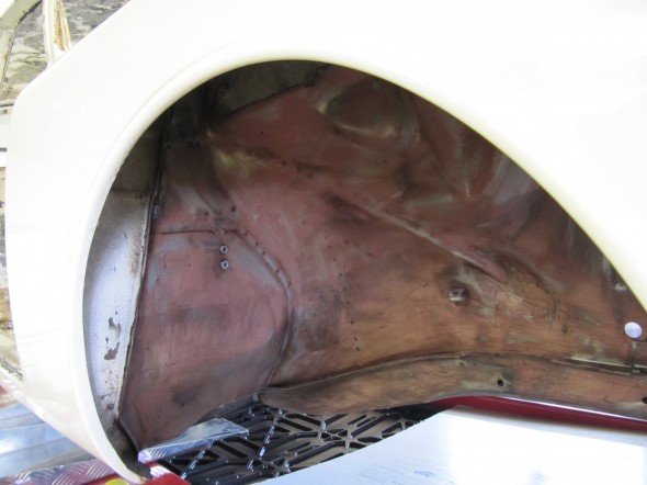
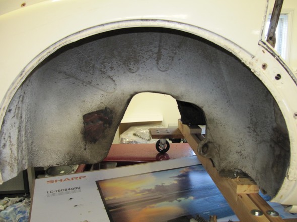
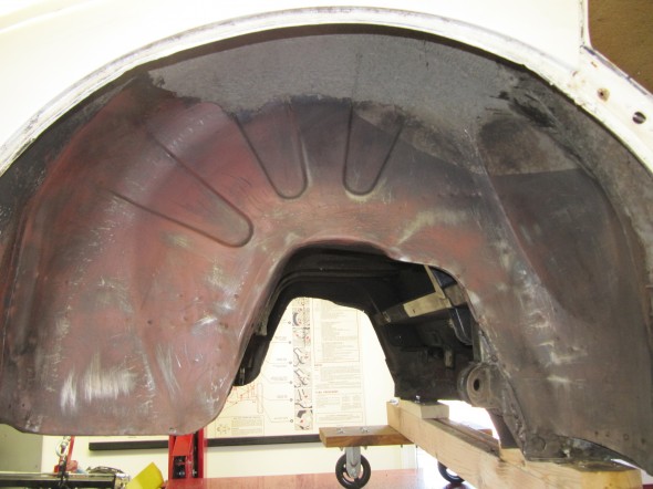
Next, I moved to the RH rear wheel well of the Jaguar and began the now all too familiar stripping process.These are before and after photos of the wheel well.

Wheel Well with Undercoating

Wheel Well with Undercoating

Undercoating Removed

Undercoating Removed

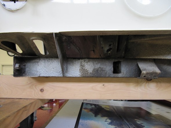
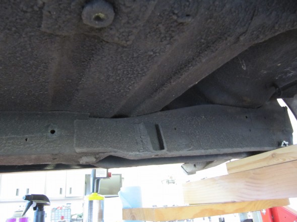
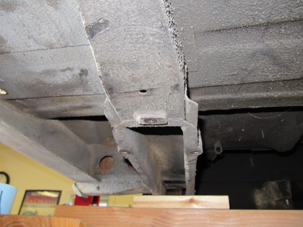
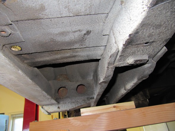
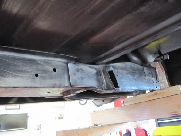
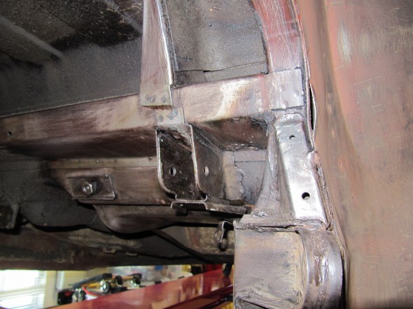
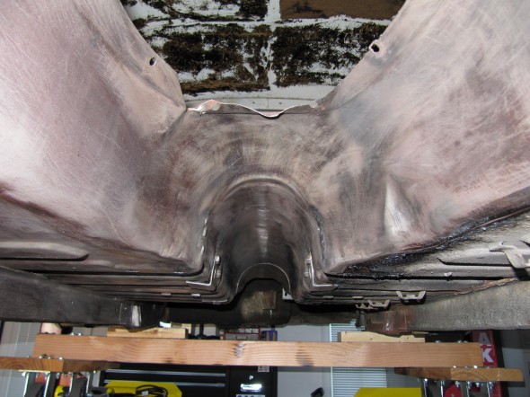
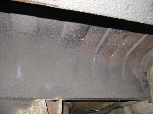
Once completing the wheel well, I moved to the RH rear frame rail and floorboard. These are the “Before.”

Rail and Floor

Rail and Floor

Rail and Floor

Rail and Floor

Rail and Floor

Rail and Floor

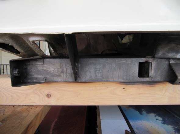
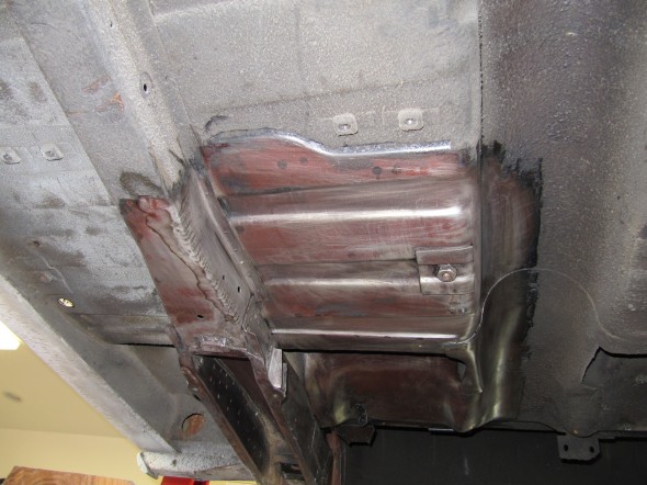
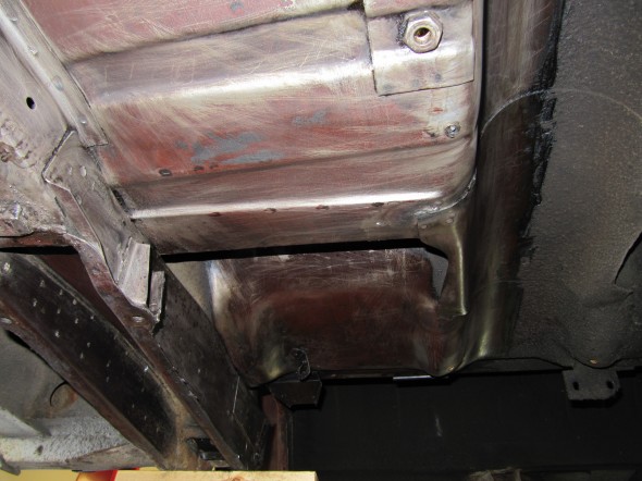
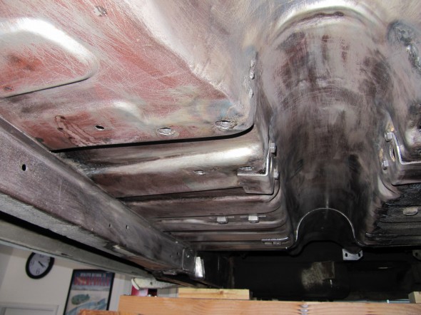
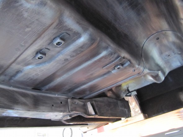
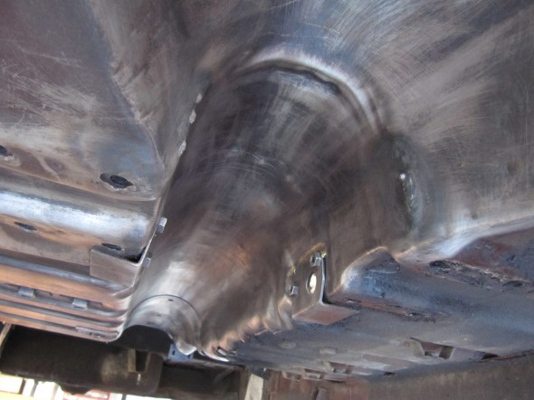
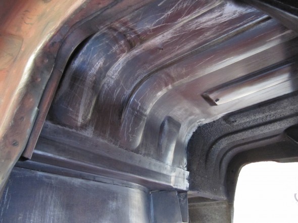
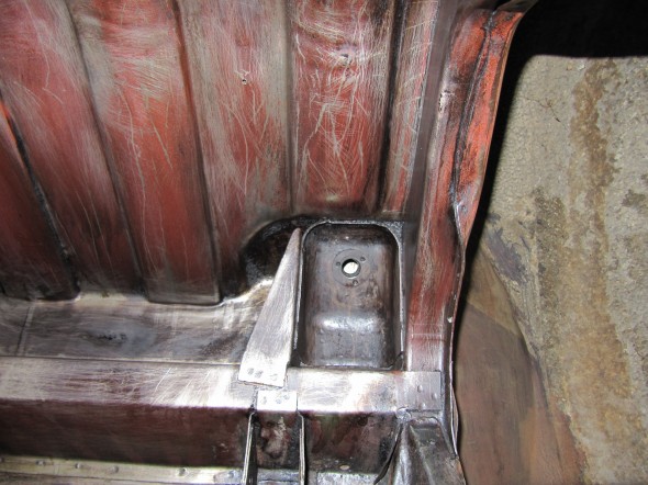
And, these are “After!”

Undercoating Removed

Undercoating Removed

Undercoating Removed

Undercoating Removed

Undercoating Removed

Undercoating Removed

I also did a little removal at the RH Rear seating bulkhead. I must say, I continue to be amazed at how rust free this car is after almost fifty years!

RH Rear Bulkhead Undercoating Removed

RH Rear Bulkhead Undercoating Removed

It is the weekend following Thanksgiving, 2012 and time for more torchwork, scraping and brushing. I put in several hours removing for grime and undercoating.

RH Floor Board & Tunnel

RH Floor Board & Tunnel

RH Floor Board & Tunnel

RH Floor Board & Tunnel

Propshaft Tunnel

Propshaft Tunnel

Propshaft Tunnel Clean

Propshaft Tunnel Clean

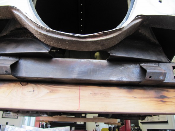
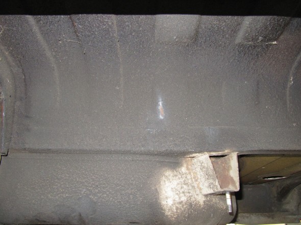
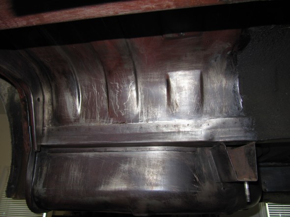
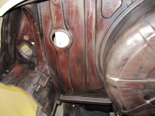
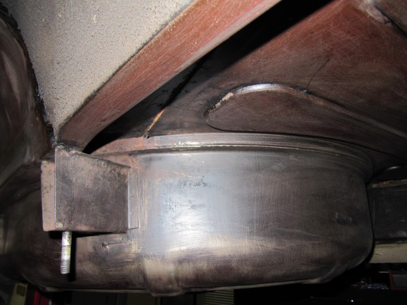
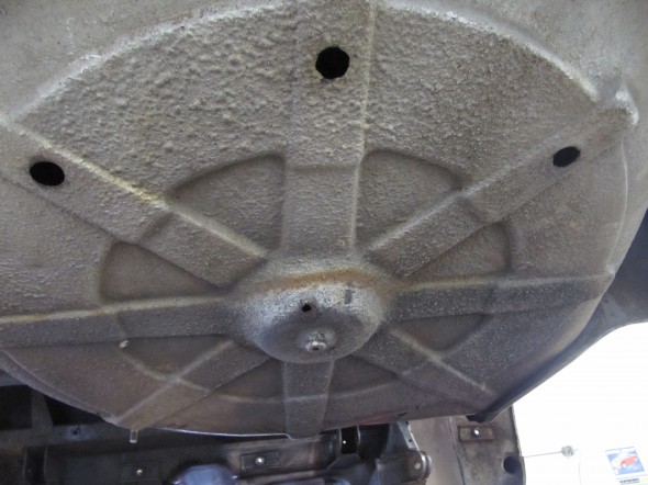
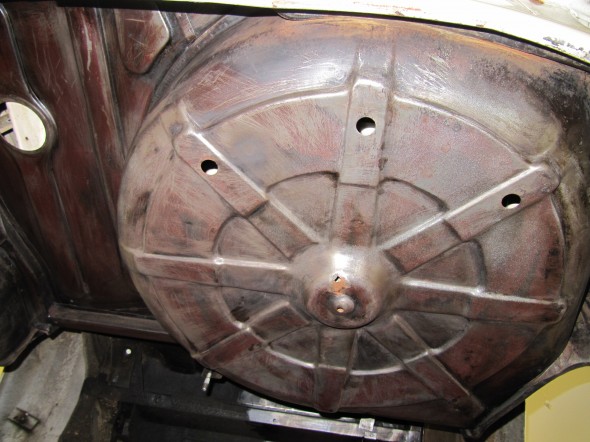
After a respite of a few days to work on the rear axle, I am now back at the underbody clean-up. As I have said, tedious work but gratifying in that the metal work is looking so good. Almost no rust at all, YET! I worked on the area behind the rear axle today encompassing the underside of the boot floor and  the spare tire storage area. Here are some “before and afters.”

Boot Floor Before

Boot Floor Before

Boot Floor After

Boot Floor After

Boot Floor Before

Boot Floor Before

Boot Floor After

Boot Floor After

Shock Mount

Shock Mount

Fuel Tank Filler

Fuel Tank Filler

Spare Wheel Container

Spare Wheel Container


Spare Wheel Container Before

Spare Wheel Container Before

Spare Wheel Container After

Spare Wheel Container After

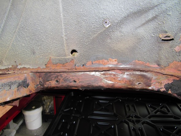
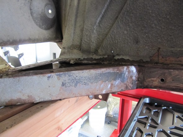
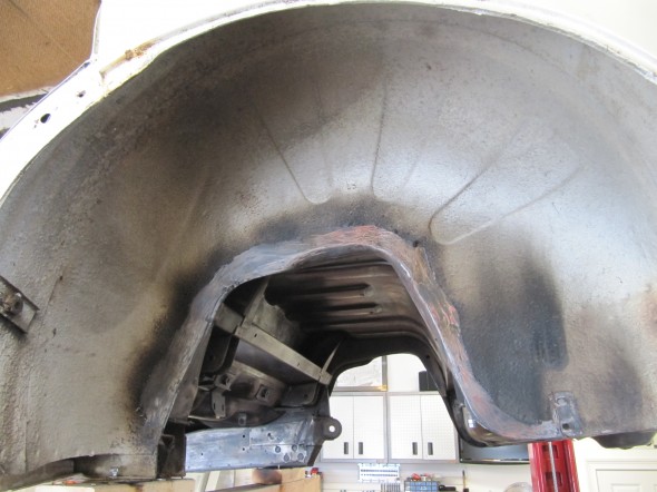
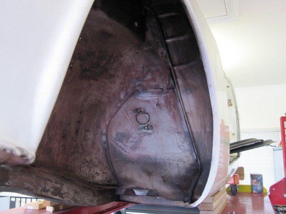
The LH rear wheel arch was the last major area to clean. I discovered a rusty spot on the rim where the inner arch and outer wing come together. Otherwise, this area cleaned up well.

These are a couple of “before” images:

Wheel Arch Before

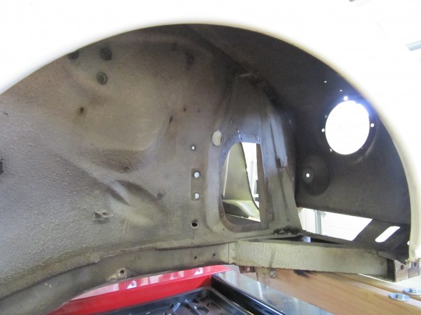
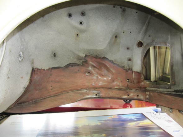
And, these show what a torch, putty knife scraper and wire brush can do!

Wheel Arch Clean

Wheel Arch Clean

Wheel Arch Clean

Wheel Arch Clean

Today is New Years Day, January 1, 2013. I mention the date, not because of New Years but because after weeks of scraping and brushing I finished the chore of removing the undercoating today!!!!

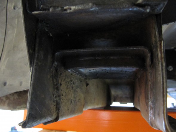
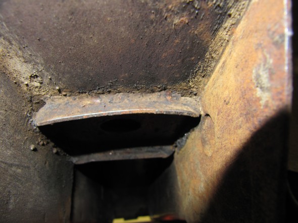
I encountered a weird issue that will require research. I was cleaning the Frame Reinforcing Channels where the leaf spring fastens to the frame and discovered a difference. The upper clamp assembly on the right side is welded to the channel directly with no gap, while the LH side has about a 3/8″ gap between  the clamp assembly and the channel. I have no idea why the two sides would be different.

LH Pad Seat

RH Pad Seat

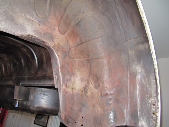
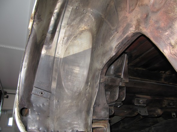
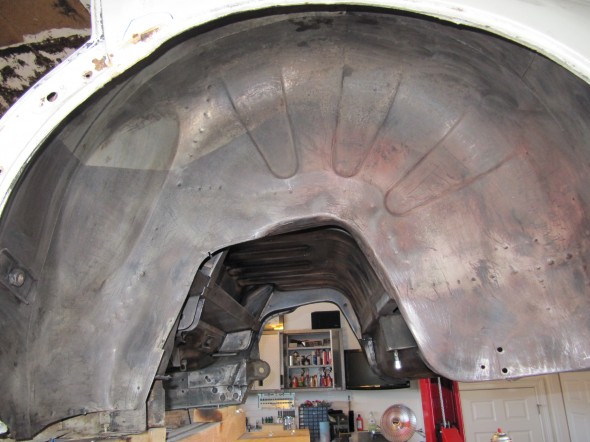
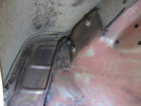
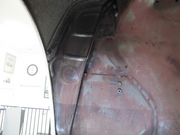
I then finished up some additional work on the front wheel arches:

LH Front Arch

RH Front Arch

RH Front Arch

I then removed the undercoating from the LH and RH Stay Brackets or Crow’s Feet. These are often rusted through, but mine are almost pristine!

LH Stay Bracket

RH Stay Bracket

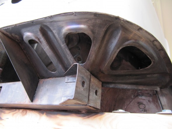
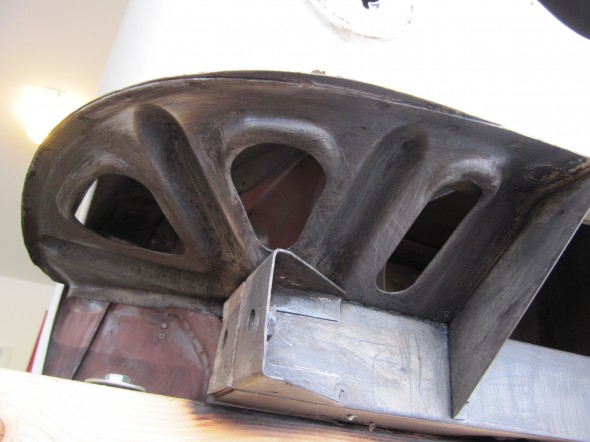
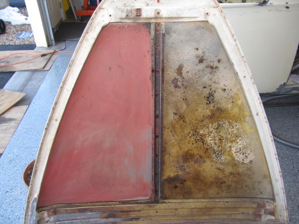
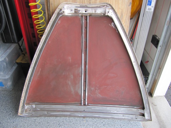
The underside of the bonnet was also covered with the bituminous undercoating that did not make for a very nice appearance. I put the bonnet on a bench painted side down. I covered the surface with towels and drenched them in mineral spirits and then covered the mess with plastic bags to prevent rapid evaporation. An hour or so later armed with a putty knife, scraper and a 3M scratch pad I was able to remove all of the undercoating.

Bonnet Undercoating Removal

Bonnet Undercoating Removal

Bonnet Undercoating Removal

Bonnet Undercoating Removal

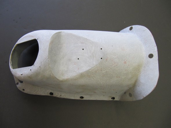
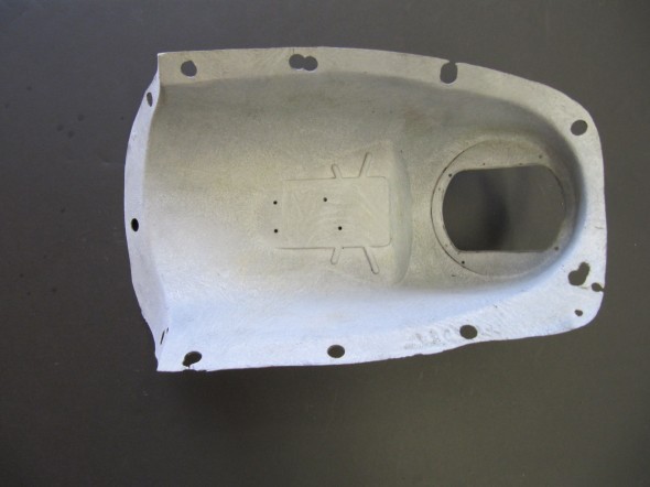
Lastly, I cleaned and then media blasted the gearbox cover. It has a few blemishes and holes I will repair before installation.

Gearbox Cover

Gearbox Cover


My Favorite Healeys

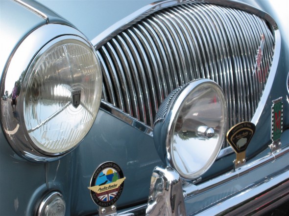
Everyone has his or her personal favorite cars. Our tastes vary and that is what makes our hobby interesting! Some favor the roadsters, others prefer the convertibles with their roll-up windows. Still others like the early Healeys that pre-dated the association with Austin. In my view they are wonderful. By clicking on the link you will see a few of my favorite Big Healeys. Cheers!

http://www.flickr.com/photos/valve-chatter/sets/72157630700453546/ 


Races

2009 Healeys Return to Bonneville

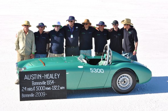
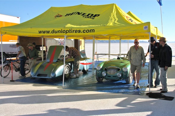
A team led by Bruno Verstraete, from Switzerland, and Steve Pike, from Australia, recreated the 1954 Healey Endurance Car and the Streamliner and returned to the Utah Salt Falts 55 years after Donald Healey set numerous speed records in the original cars. One hundred and fifty to two hundred Healey faithful came together in mid-september in Wendover, Utah to observe the running of the cars and to share their enthusiasm for the marque. I had to fly out from Virginia to see history being recreated, if not made!

The owners never intended to break DMH’s records, wanting only to get close. Weather was a bit of a problem delaying the runs by a day. The Endurance Car ran a respectable speed of 127 mph and the Streamliner, while plagued with supercharger and parachute problems, managed 149 mph.

The Healey Team on the Salt Flats

The following link will direct you to a gallery of images memorializing this very special event:

 http://www.flickr.com/photos/valve-chatter/sets/72157630732345654/


2005 Australian/U.S. Healey Challenge

Primarily because of the hard work of Jeff Johnk, the 1990 Healey Challenge between the Brits and the U.S. was revisited in 2005 with the Aussies versus the U.S. Healey Drivers. It is an understatement to say the the Australians cleaned our clocks, but it was all in good fun, and a special treat to all who saw the cars around the country. I had the chance to see the combat at Summit Point in West Va. and at Virginia International Raceway (VIR).

Enjoy the images of the Challenge at the following link:

http://www.flickr.com/photos/valve-chatter/sets/72157630732818050/


zz