Air conditioning the Mk2 is not an easy task. The primary problem is lack of space. The engine bay is already crowded and adding a compressor, hoses, condenser and related hardware is a challenge and then one must find a place for the evaporator. Jaguar had dealers install the evaporators in the boot with cool air outlet vents then routed to the shelf behind the rear seat. Less than ideal. If one had passengers, the cool air would be blowing on the their necks, and we Americans tend to like our auto air conditioners blowing a blast of cool air in our faces! So, it is fair to say that air conditioning systems in the MK2 represented a series of design compromises.
The best place to start with this project is understanding what the factory chose to do to address the U.S. market’s air conditioning needs. JCNA Jaguar Air Conditioning Judges’ Guide is a very helpful source of information filled with wonderful factory documentation. In the narrative of this post, I will refer to this document as The Guide. The Guide addresses the air conditioning systems for a number of models for the period 1955-1971. As the Guide and it’s primary author, George Camp, point out with supporting documentation, “air conditioning was a North American desire and effort. Factory installations of air conditioning systems were direct result of research and development work carried out in the Southeast and Western United States.”
Another useful resource is a document authored by Vintage Air: Their guide Vintage Air’s Air Conditioning Basics provides an easy to understand summary of air conditioning fundamentals for the novice – like me!
Of course, one of the very best sources of information for those who are attempting to install air conditioning in their mid-sixties Jaguar is the group of brave souls who have actually done it or are in the process. Robert Seligman was particularly helpful. Bob and I exchanged many, many emails about air conditioning particulars. Other helpful parties include in no particular order: Sterling Forsythe, Ed Nantes, Stuart Brainard, Glenn Logan, Ton Tulleken, George Leicht, Phil Aldridge and John Stefanik. My thanks to all for sharing their knowledge, experiences and photos!
The Rose 1964 Jaguar Air Conditioning System
The air conditioning system I developed for my car is comprised of a number of original or “original-type” components as well as contemporary parts sourced from current vendors. One decision, made early in the chronology of this exercise, was a key factor in determining how my system would be developed. I knew that I wanted to have cool air blowing in my face which meant air outlets in the dash.
I had no objection to housing the evaporator in the boot, but since there is just no practical way to get cool air from the boot to the dash I was reconciled to accepting the evaporator placement in the front of the car. I am not crazy about the “all-in-one” units that fit under the dash. I wanted something that at least appeared to be integrated into the car rather than added-on. I suppose that someone more creative than I could figure out how to mount and hide an evaporator under and behind the dash, but that was beyond my capabilities. In the end, I figured that a well insulated evaporator mounted on the firewall in the engine bay was the route I would take.
As others have done, I determined when I started this process that the kit from Rock Browning’s RetroAir company in Texas was my best bet. So I purchased his kit. However, as my journey progressed and I learned more about this subject, I decided to modify Rock’s approach. My deviations from the RetroAir kit are explained below. This is no knock on the RetroAir kit. I simply decided to take a different path regarding some aspects of the system.
At the heart of the RetroAir system, is a single belt, “V” groove pulley system utilizing an idler pulley on the back of the classic “V” belt to improve pulley wrap. My preference after discussions and consultations with many is that while a single serpentine belt works just fine, it is preferable to have at least two belts driving the system when using “V” belts. JUST MY OPINION AND ULTIMATELY MY DECISION. This is a big decision in that mounting brackets and pulleys are effected.
The RetroAir Kit
My description of the process begins with the RetroAir kit because that is where I started. The following description was taken from the RetroAir web site and describes the purchased system.
| This is our Original system that took over 3 years to develop so it would look and perform like it belonged in a Jaguar! It includes some of the most efficient, custom made parts available to cool a car. During development we looked at every aspect of cooling this model car including using the Heater Box and Ducts, as a European Competitor is doing. All A/C systems produce volumes of Condensation which will ruin the Metal Heater Box and Ducting. Since the Metal Ducting is an integral part of the Body construction strength on the Mark II and Variants, the resulting Rust and Rot can be dangerous and expensive to repair. Likewise, we rejected the Trunk mount and “Hang Down” units for inadequate performance, and aesthetic reasons. The results of our work is “Blowin in Your Face” A/C that looks perfectly at home in a Classic Jaguar.We use only the best for these Kits: A 30 tube, Evaporator design that produces 16,000 BTU’s and will cool any large sedan. Our Condenser is a “4 pass” Multi-Flow with 13 passages in each tube and produces well over 20,000 BTU’s. Other units can not come close to this! We use a new Sanden/Behr Rotary Compressor which is the most popular and reliable aftermarket Compressor available, and easily cool the Mark II and it’s Variants. Our Custom Made Barrier A/C Hose Assemblies have 2 reinforcing plies and properly clocked Fittings. The results of all this care are Mid-Thirty to 40 Degree vent temperatures as reported to us by users and shops alike! |
- New Custom Evaporator – UPGRADED!
- New Custom Blower Assembly – UPGRADED!
- New Sanden/Behr Rotary Compressor (Chrome Optional)
- New Receiver/Drier with Hi-Lo Switch
- New Hi Tech Multi-Flow Condenser (See details Below)
- New Condenser Fan
- New Custom Barrier Hoses with Properly Clocked Fittings
- New Interior Louvers and Duct Hoses
- All Mounting Hardware & Brackets
- Full Instructions & Pictures
|

Installation
Radiator
I had chosen to replace the original radiator with an aluminum unit made by Wizard to improve cooling and assist with the air conditioning system. I purchased the radiator from RetroAir with my other air conditioning components. It looked beautiful!
I ended up not using the Wizard unit because it did not fit properly. It sat too high, contacting the bonnet, and because of the wider upper tank it did not allow sufficient space for the wiring harness that travels across the front of the radiator from the LH valance to the RH valance. A sad and expensive lesson. I could have modified the aluminum unit to fit but could not solve the wiring harness problem to my satisfaction.
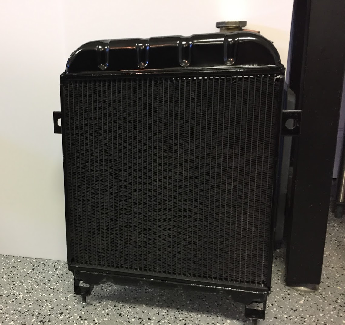
I decided to return to my original radiator but had it recored by Blue Sky Radiator with a modern cooling matrix. I painted the sides of the assembly and the lower tank with POR-15 after using their metal prep product. I then used progressively finer sandpaper to prepare the upper tank surface and then painted it with a Duplicolor self etching primer (three coats) and Duplicolor Engine High Temperature Gloss Black spray paint (also three coats). I just lightly dusted the front of the core with the high temperature paint as I wanted to avoid affecting the heat radiation properties of the radiator to the extent possible. I did not paint the rear face of the core. I was pleased with the results:
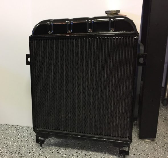
Painted and Recored Original Radiator
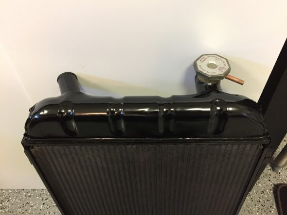
Painted and Recored Original Radiator
Installation guidance for the engine driven fan, fan shroud, and the radiator may be found in the “Engine Cooling” post: https://valvechatter.com/?p=5536. The location of the air conditioning Sanden compressor did require a modification to the shroud that is also detailed in the “Engine Cooling” post.
Condenser
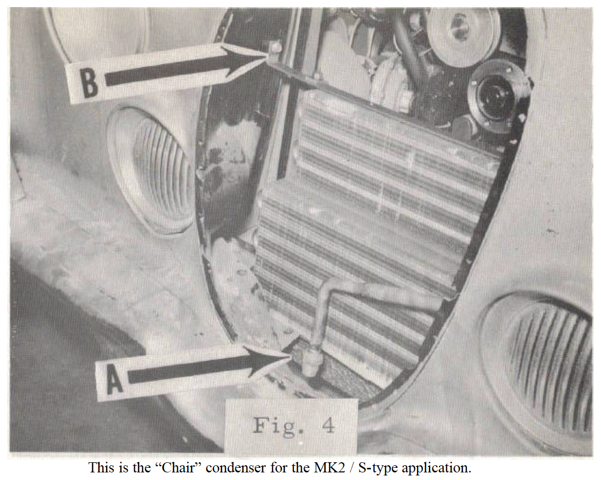
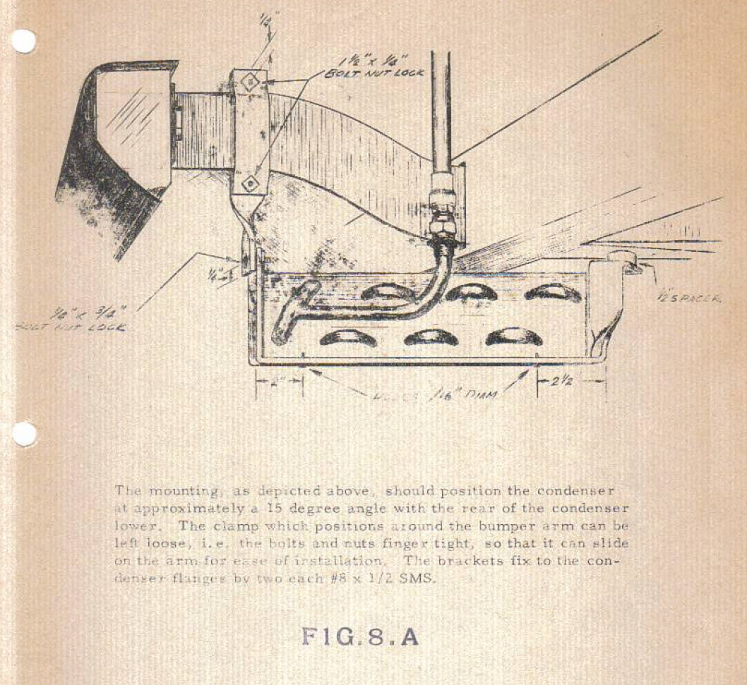
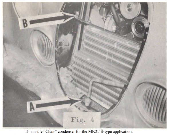
The MK2 air conditioning system as conceived by Jaguar used a “stepped” condenser in front of the radiator and another below the front bumper. As The Guide describes, “The condenser for these cars was very interesting and was referred to as a “Chair” condenser due to its unique shape. Note some cars (MK VII, MK VIII, MK IX, MK 10, 420 G, S-type, MK2, & 340), had dual condensers. One located prior to the radiator and one slung beneath the bumper. They were connected in parallel (like a parallel electrical circuit). A fabricated road debris guard of perforated steel mesh or a heavily louvered cover was fitted and painted black for obscurity.” Figure 4 and Figure 8.A below are sourced from The Guide.
Chair Condenser Mounting
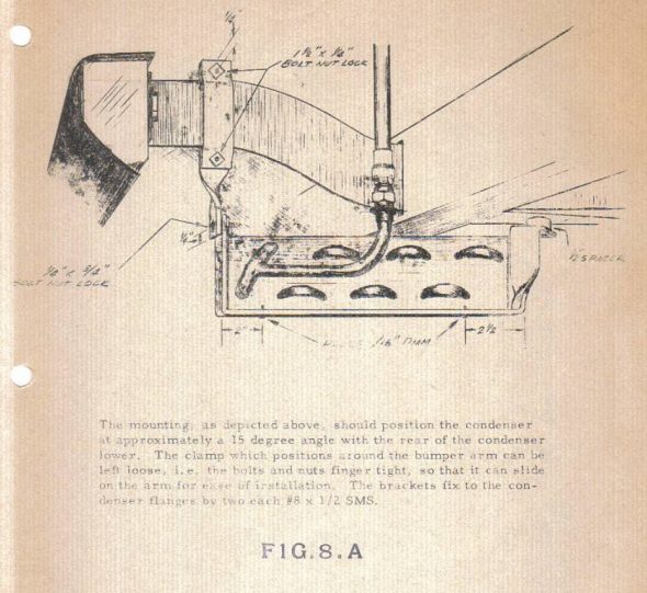
Condenser Mounting Instructions
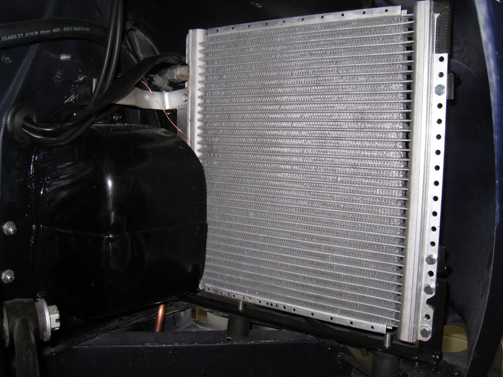
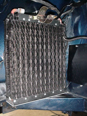
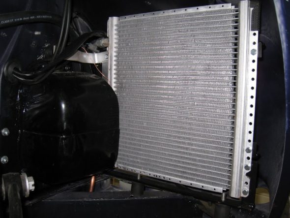
Some contemporary MK2 systems have used two condensers, usually mounted not under the car, but in one of the front wheel wells. Here are two examples:
Wheel Well Condenser Installation
Wheel Well Condenser Installation
I decided to at least initially install my system with only one condenser – the one supplied in the RetroAir kit. This decision is not based on empirical analysis. Rather, I am betting that with modern day condenser design and with the addition of an electric fan, not used by Jaguar at the time, that the system will operate effectively. Only time will tell.
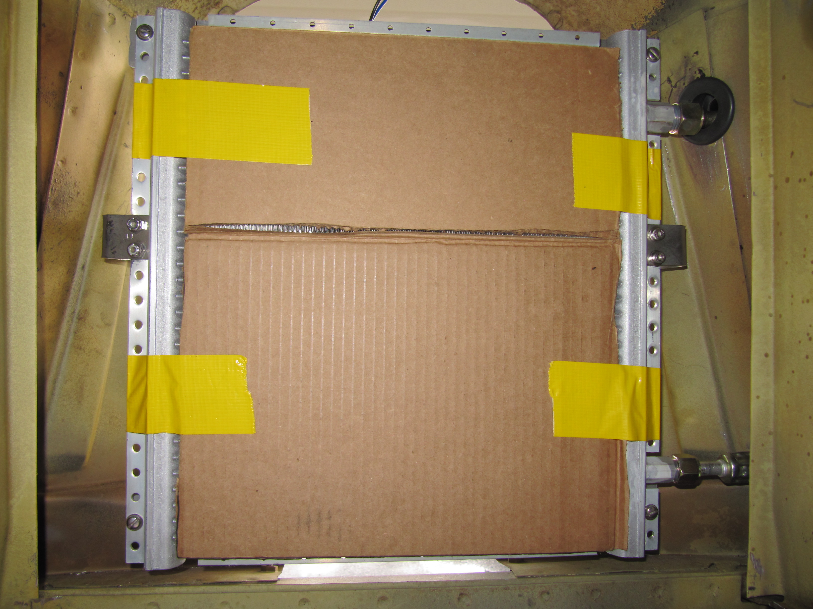
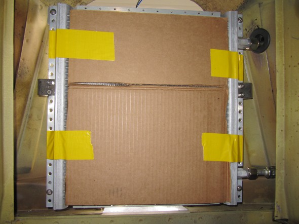
So, I began the condenser installation. As directed in the instructions provided, I measured 13 inches from the bottom grille pan on the RH side and marked a center point. At the same height I measured two inches from the radiator support/brace. Where the two measurements intersected on the side panel valance (wheel well) I marked the location of the center of a 1 – 1/4″ hole to be drilled. I then marked the center point for another hole to be drilled 9 – 3/4″ directly below the top center mark.
Before drilling any holes I inserted the condenser into the grille cavity to make sure things would line up properly. RetroAir states emphatically that the condenser should be at least one inch from the face of the radiator. Satisfied that I had things lined up properly, I drilled the two 1 – 1/4″ holes in the side panel and carefully filed and sanded the hole to insure I had a smooth surface. I then inserted two supplied rubber grommets into the holes. These holes provided entry for the coolant hoses to the condenser connections from the drier and evaporator. The top hole is for the large connection and the lower hole is for the smaller diameter connection. I then attached the hoses to the condenser fittings as loosely positioned it in the grille cavity.

Lower Condenser Fitting Hole with Grommet

Upper Condenser Fitting Hole with Grommet
Condenser Brackets and Hose Fittings from Engine Bay
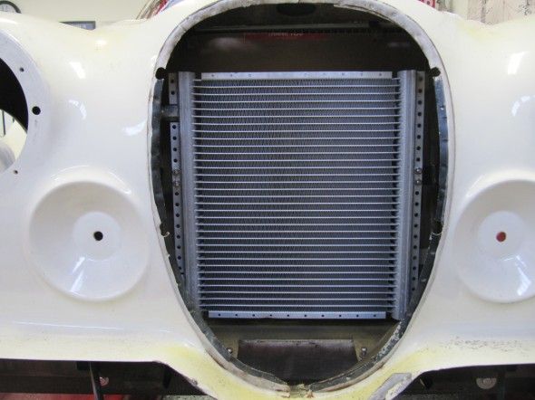
Condenser Installed
I then, by trial and error, bent the two brackets supplied in the kit so as to mount to the series of vertical holes on the left and right side of the condenser. I drilled two small holes for #10 stainless socket-head machine screws into the LH and RH side panels of the wheel well to accept the front-most end of the mounting brackets. These two brackets firmly and securely held the suspended condenser in the cavity. Nylock nuts were used on all the fittings. The brackets will be powder coated black.

Condenser Bracket LH
Condenser Bracket RH
Electric Fan
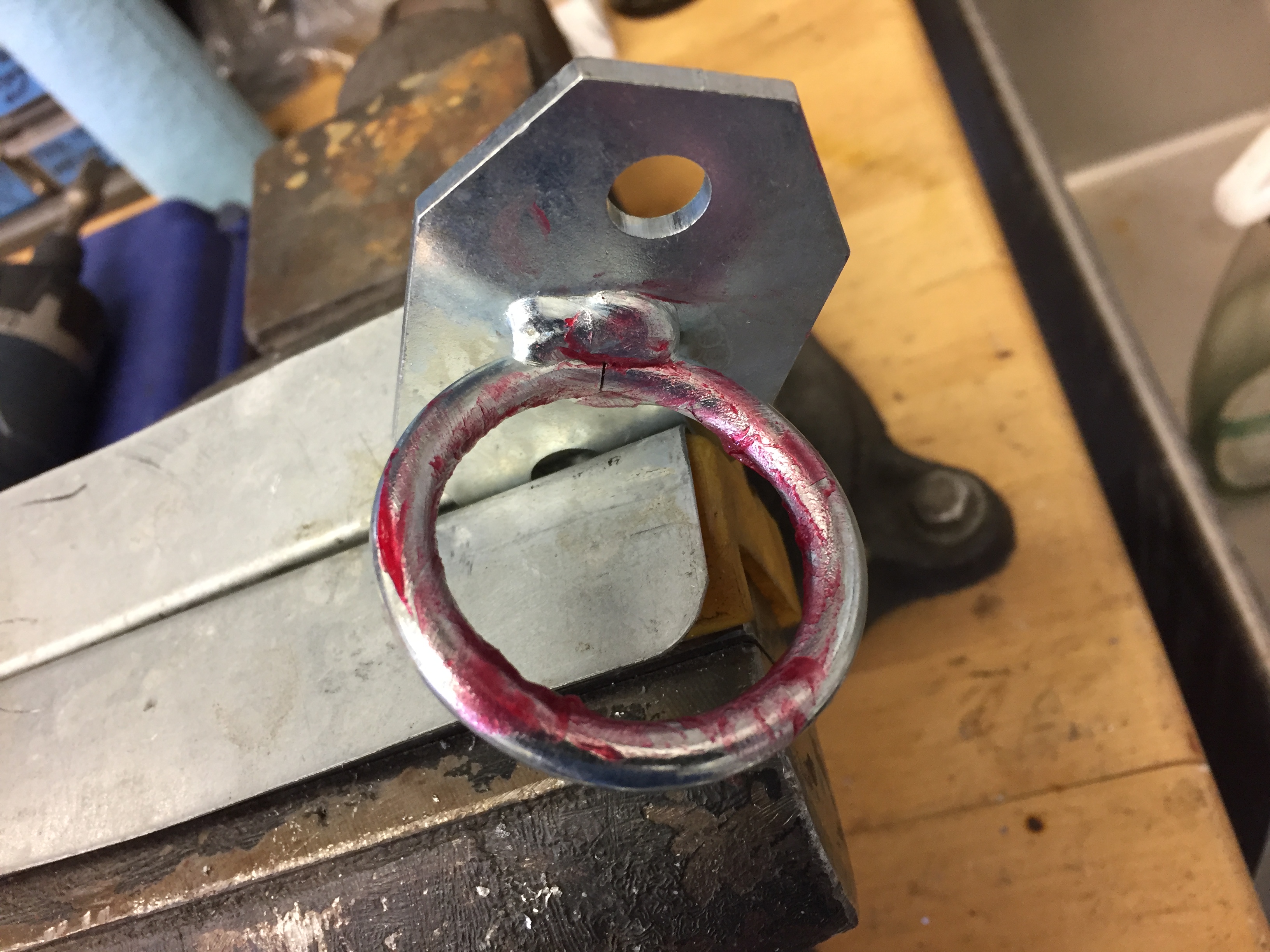
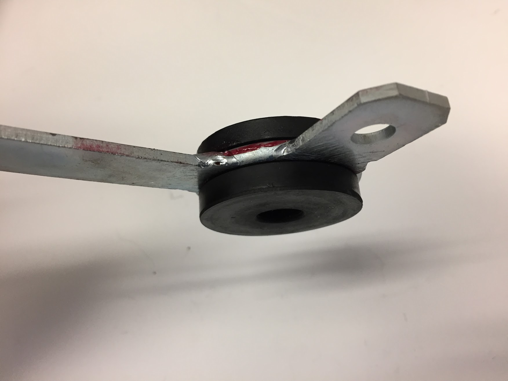
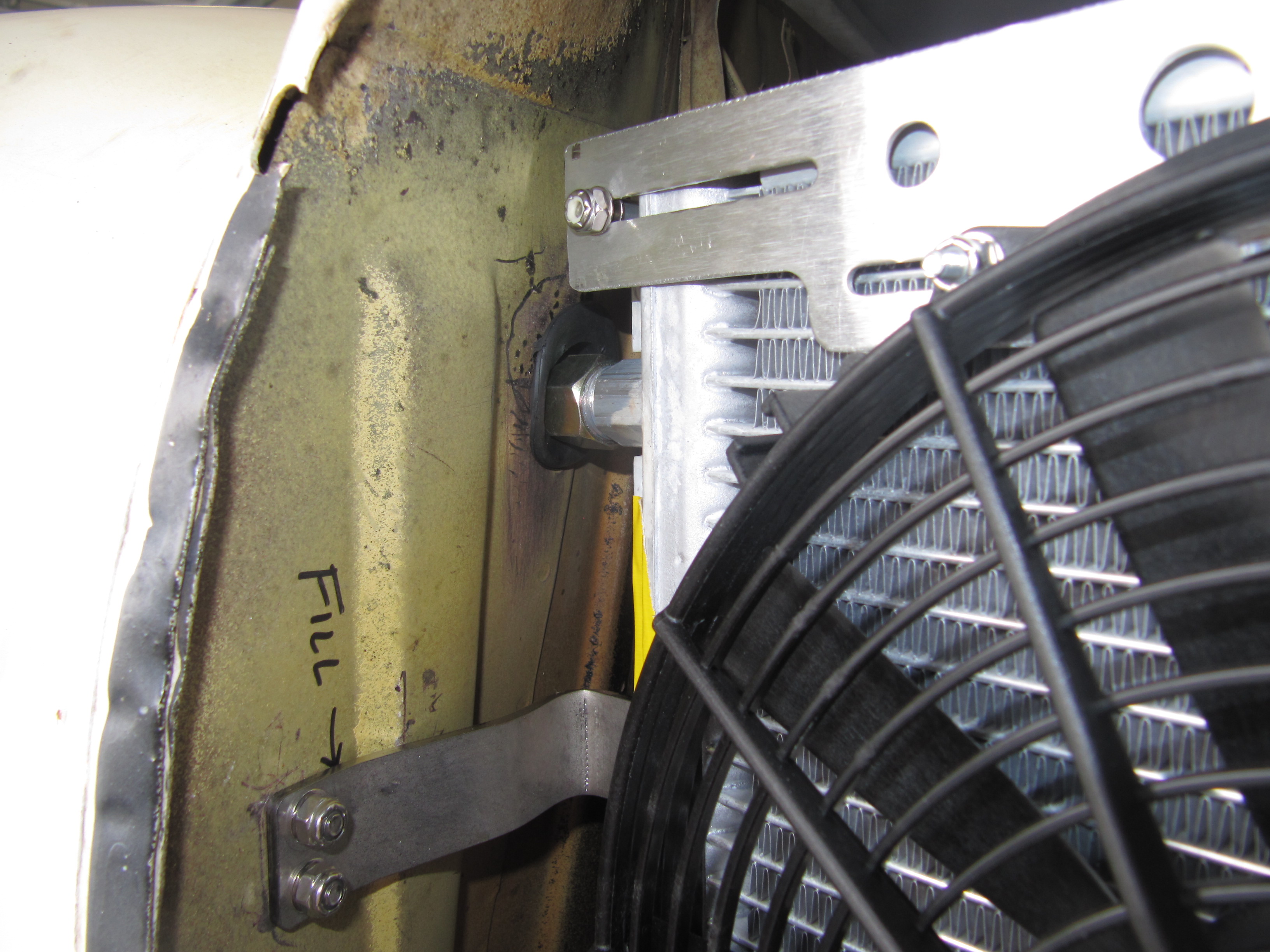
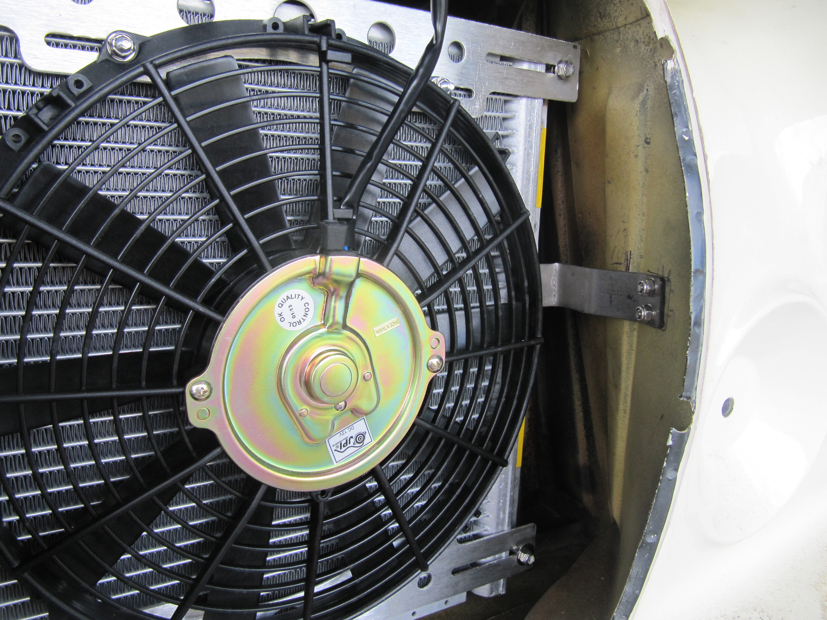
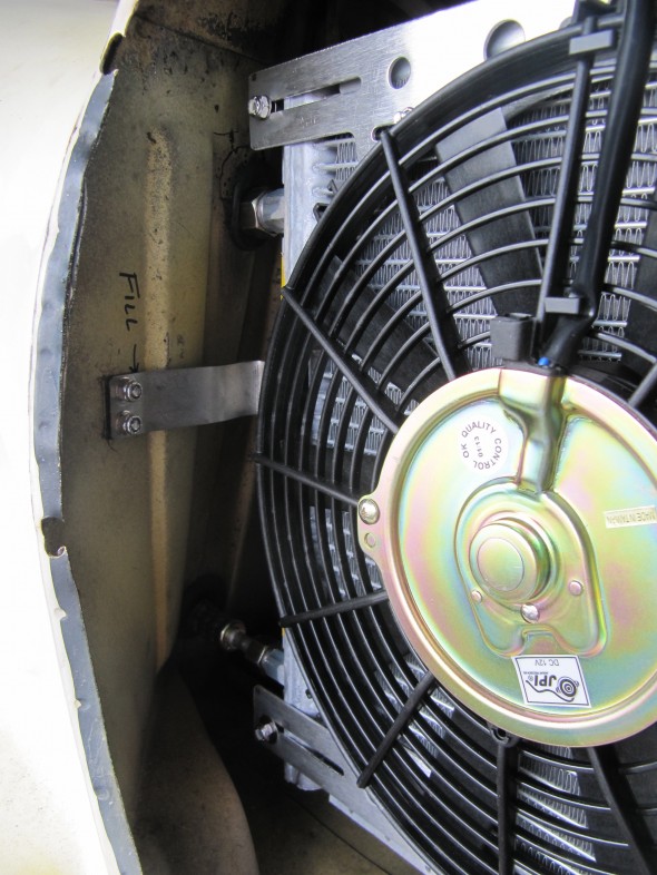
The kit utilizes an 11″ 5.3 AMP JPI Fan. The instructions call for mounting the fan directly to the condenser with plastic ties, but I wanted to try something different so I ordered a pair of aluminum fan mounting brackets from Old Air Products.Old Air Products Fan Bracket Kit
I shortened the ends of each bracket and welded in a filler to fill the gaps on the ends and then used the brackets, fastened to the fan and the condenser to hold the fan in place. I much prefer the appearance of this approach. Just esthetic, but more pleasing to me.
Old Air Products Fan Brackets
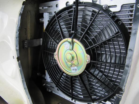
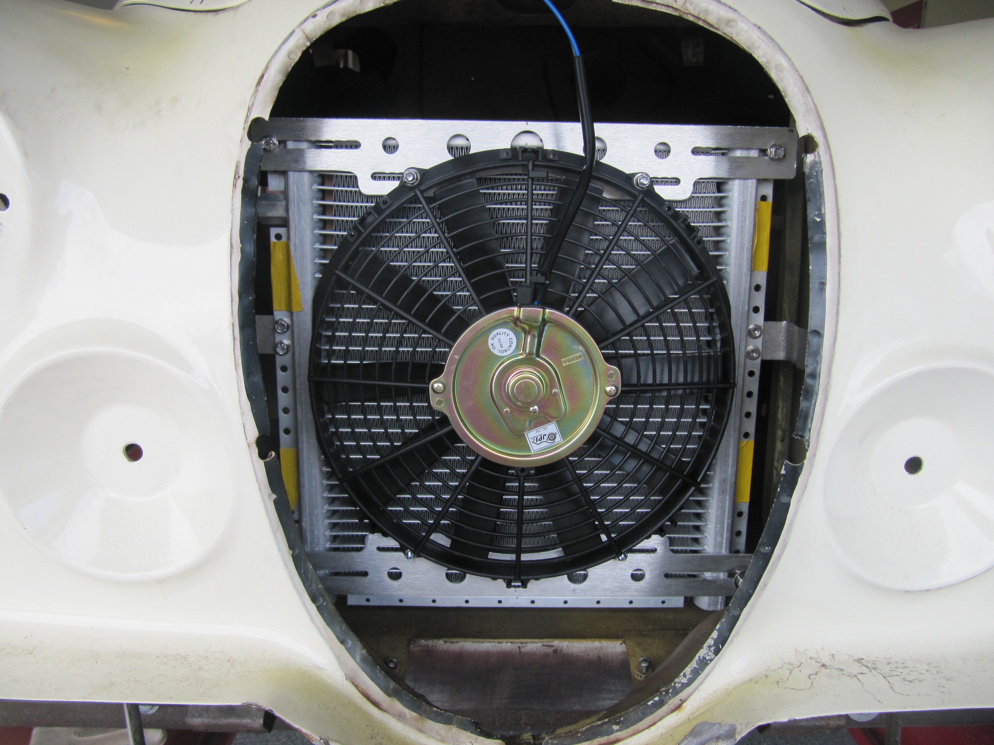
SPAL 12 Inch Fan
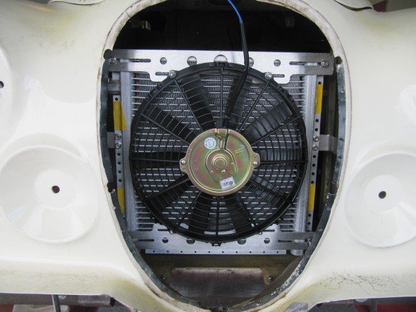
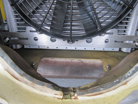
Installed Condenser and Fan
Compressor
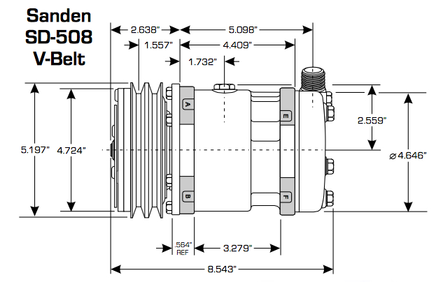
MK2 air conditioning installations incorporated an aluminum York compressor. The RetroAir kit as stated above provides a Sanden/Behr 5H14-V Rotary unit that is commonly used in the industry. My system utilizes the compressor in the RetroAir kit.
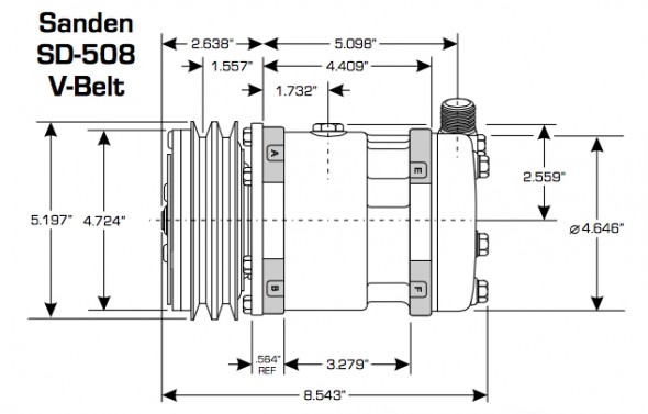
Sanden SD 508/SB 5H14-V V belt compressor
sanden compressor service guide
Alternator
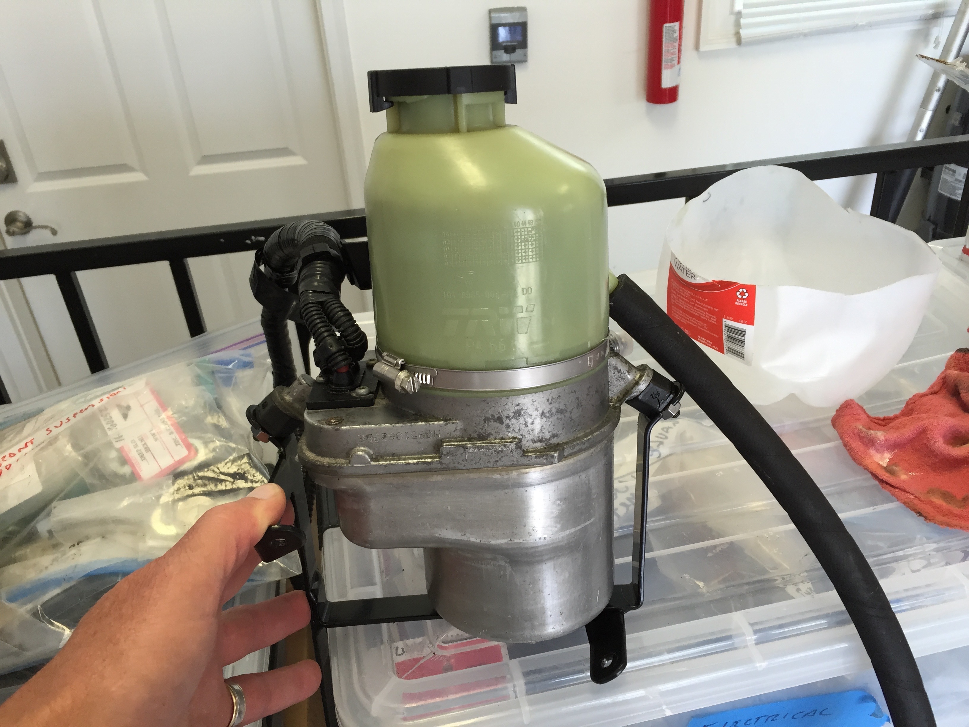
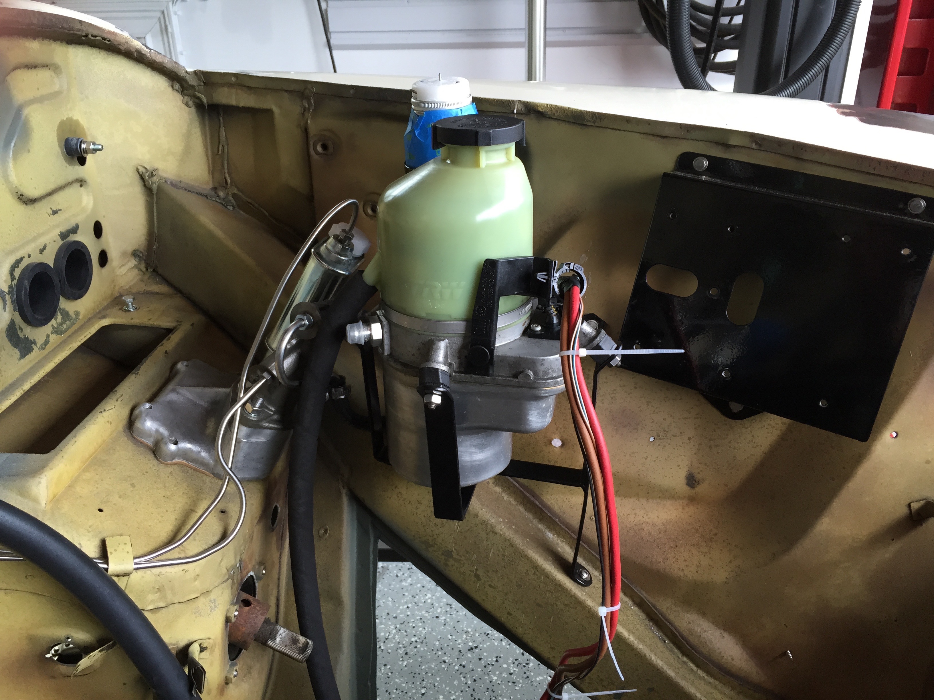
Rock Browning will supply an alternator as a component of his kit including the accommodation for a power steering pump. For several reasons, I opted to provide my own alternator. I am using an electric power steering pump with a rack and pinion steering system and the pump requires significant amperage at full turn. I am also adding a number of other modifications such as power seats so I have chosen a high output Hitachi alternator for my application. The Hitachi alternator is described in more detail in the “electrical components” post.
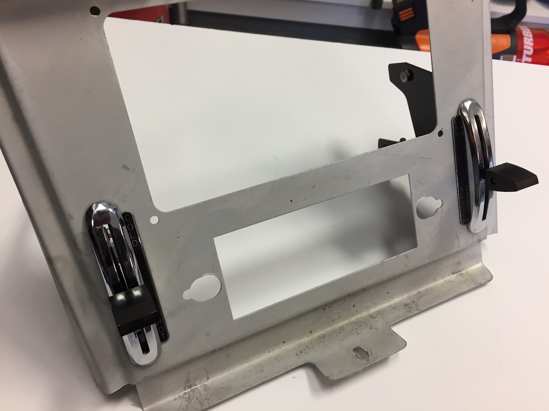
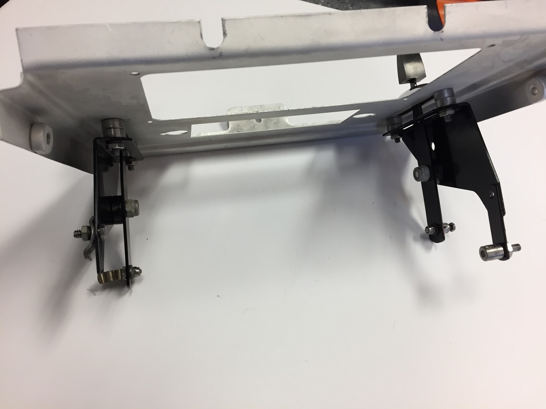
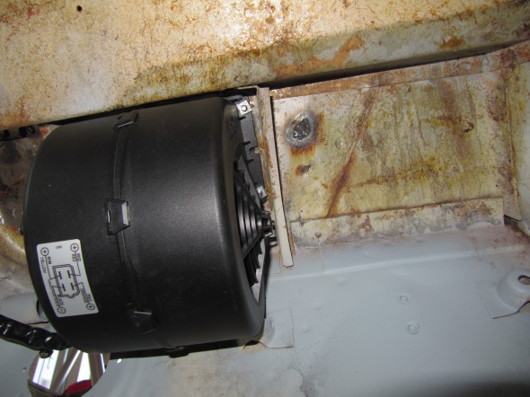
Blower/SPAL Fan
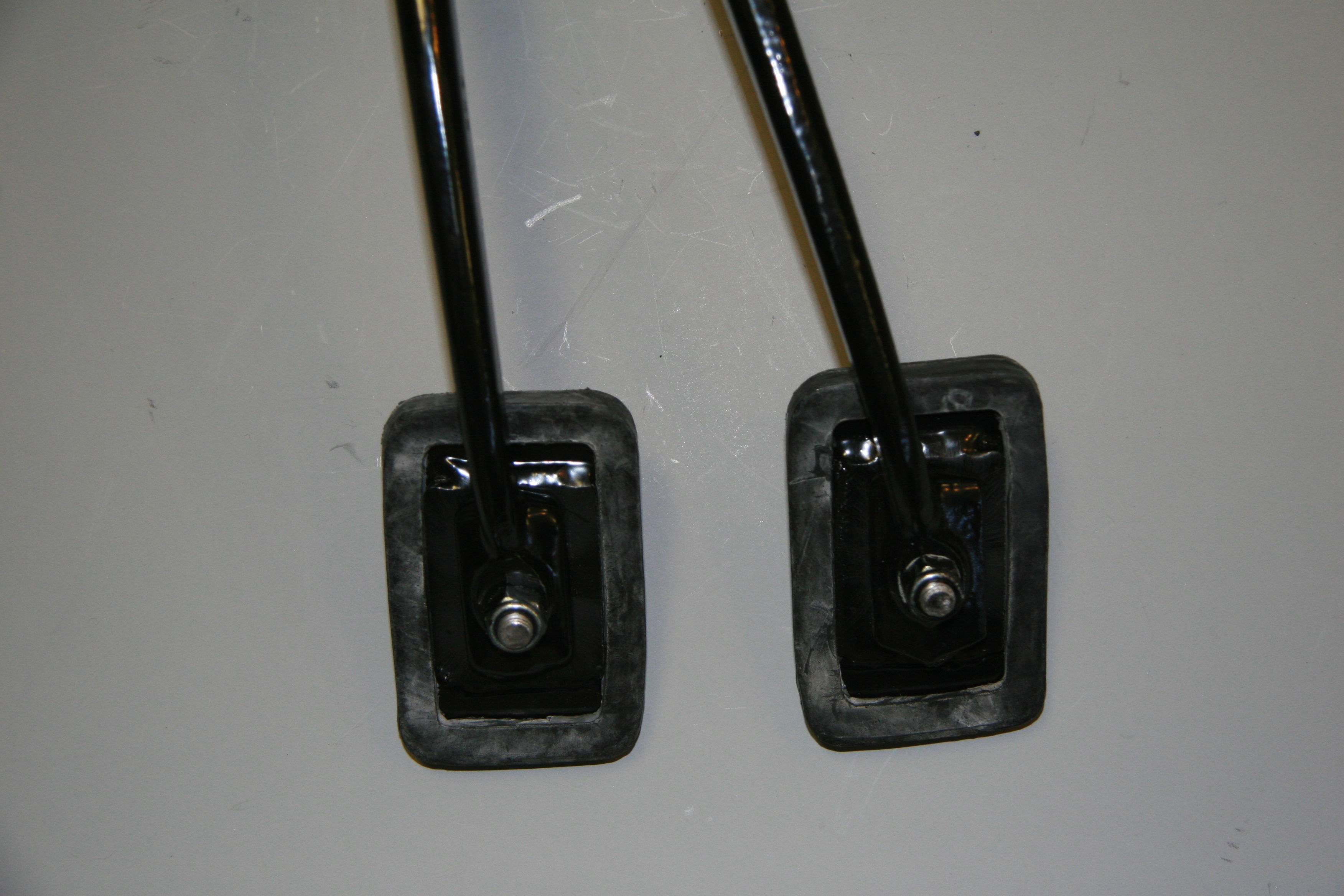
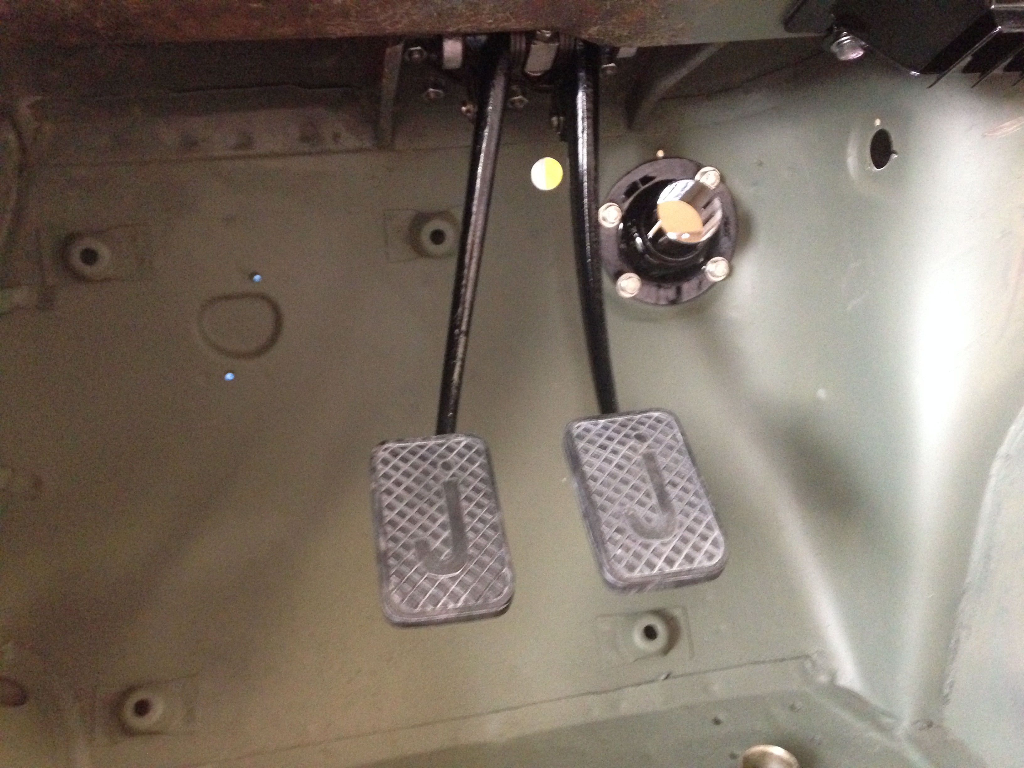
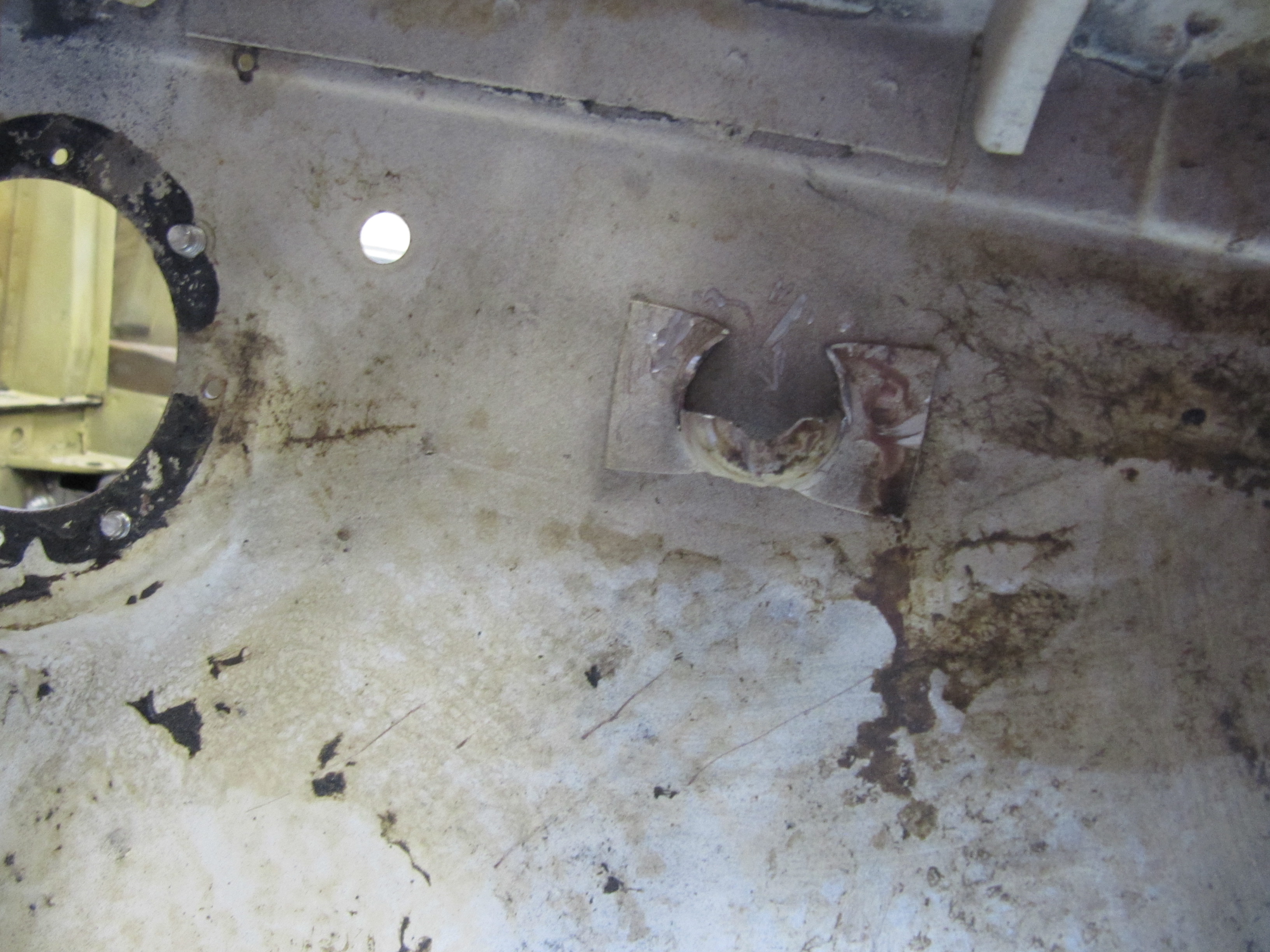
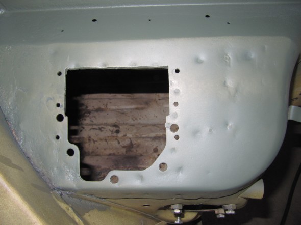
The RetroAir kit uses a 3 speed, Spal Blower (Type 009-A70-74D-12V ) and according to Rock Browning owner of RetroAir it draws a maximum of 16 amps. My system utilizes this blower. To prepare for the installation of the blower, it is first necessary to remove the battery, battery tray, and the battery tray braces. Removing the braces requires drilling out spot welds and breaking the braces from the firewall/footbox. I had already removed the RH pedal box blanking cover.
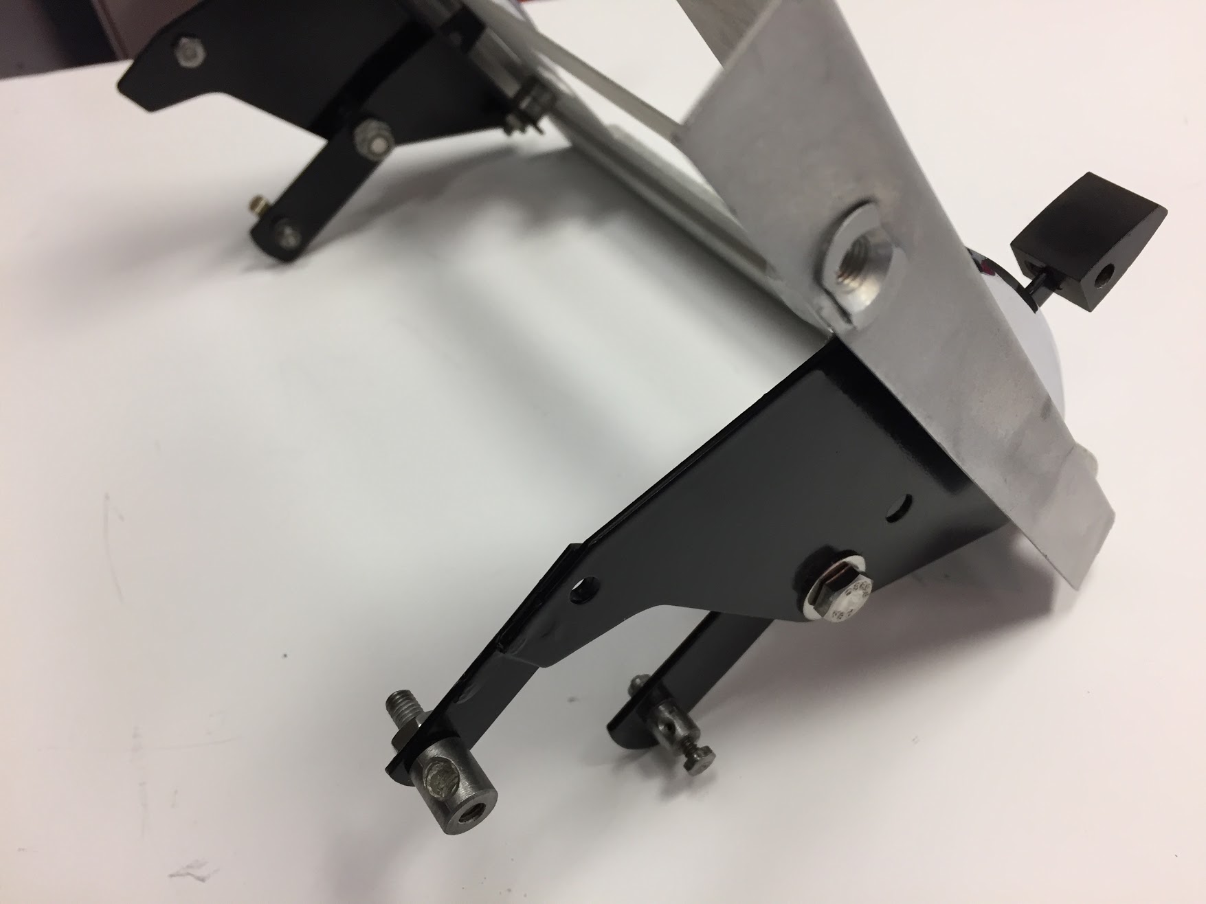
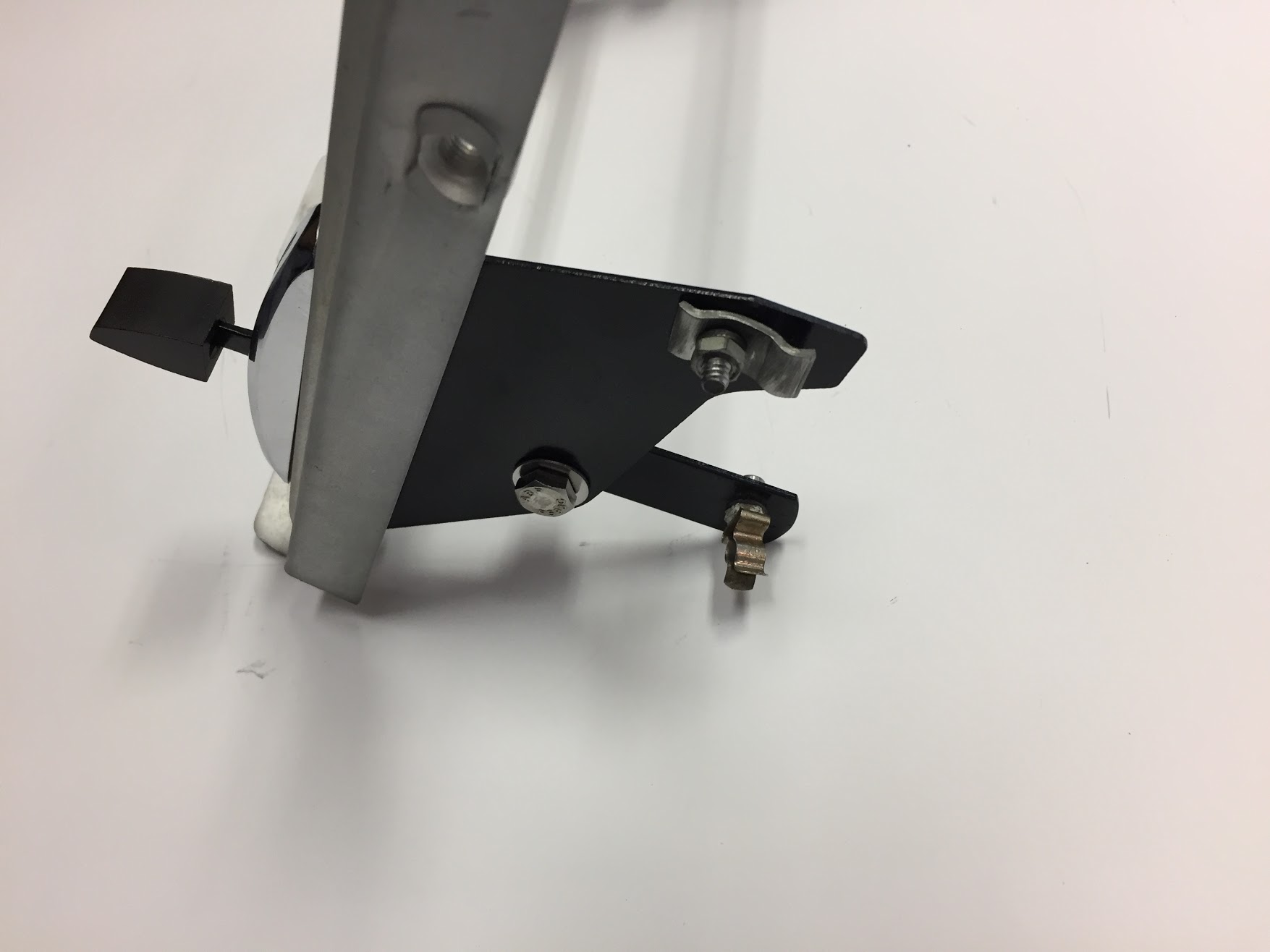
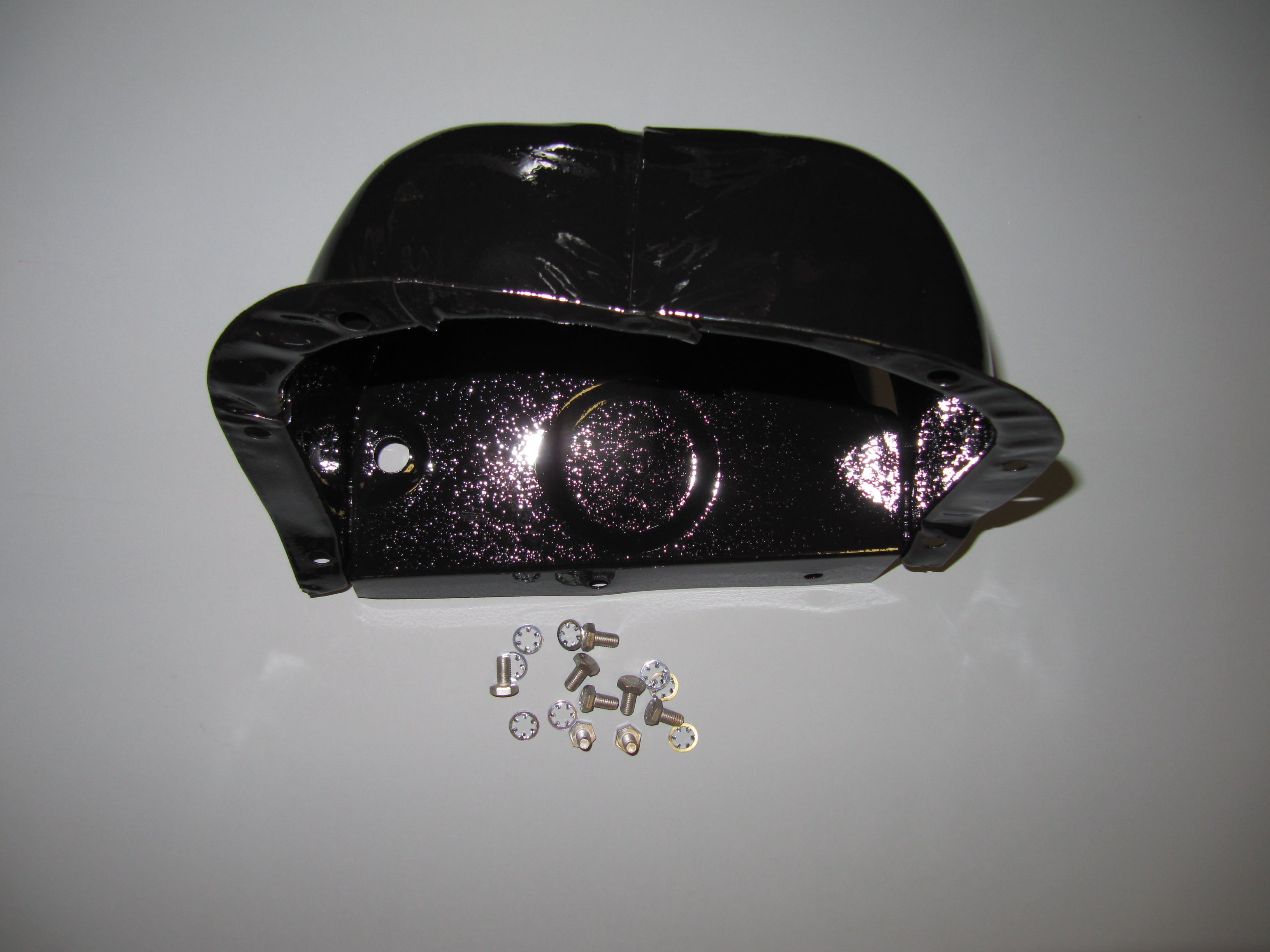
Removing Battery Tray Braces
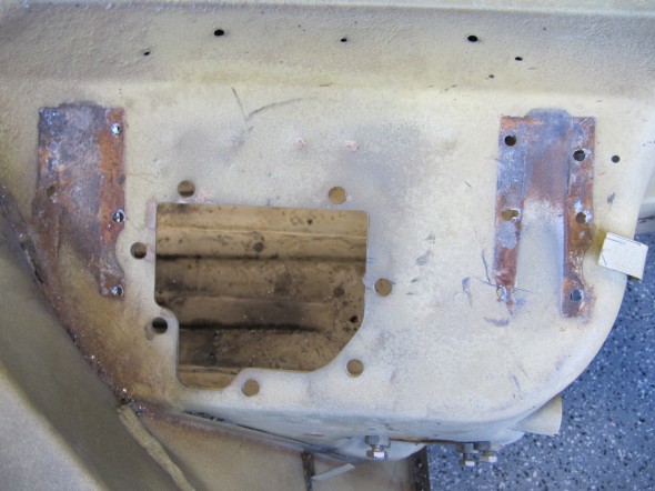
Footbox with Battery Braces Removed
I then removed the paint and “cleaned up” the area. I will hit the rusty area in the lower left corner with the media blaster later. The metal is solid.

Footbox Buffed clean
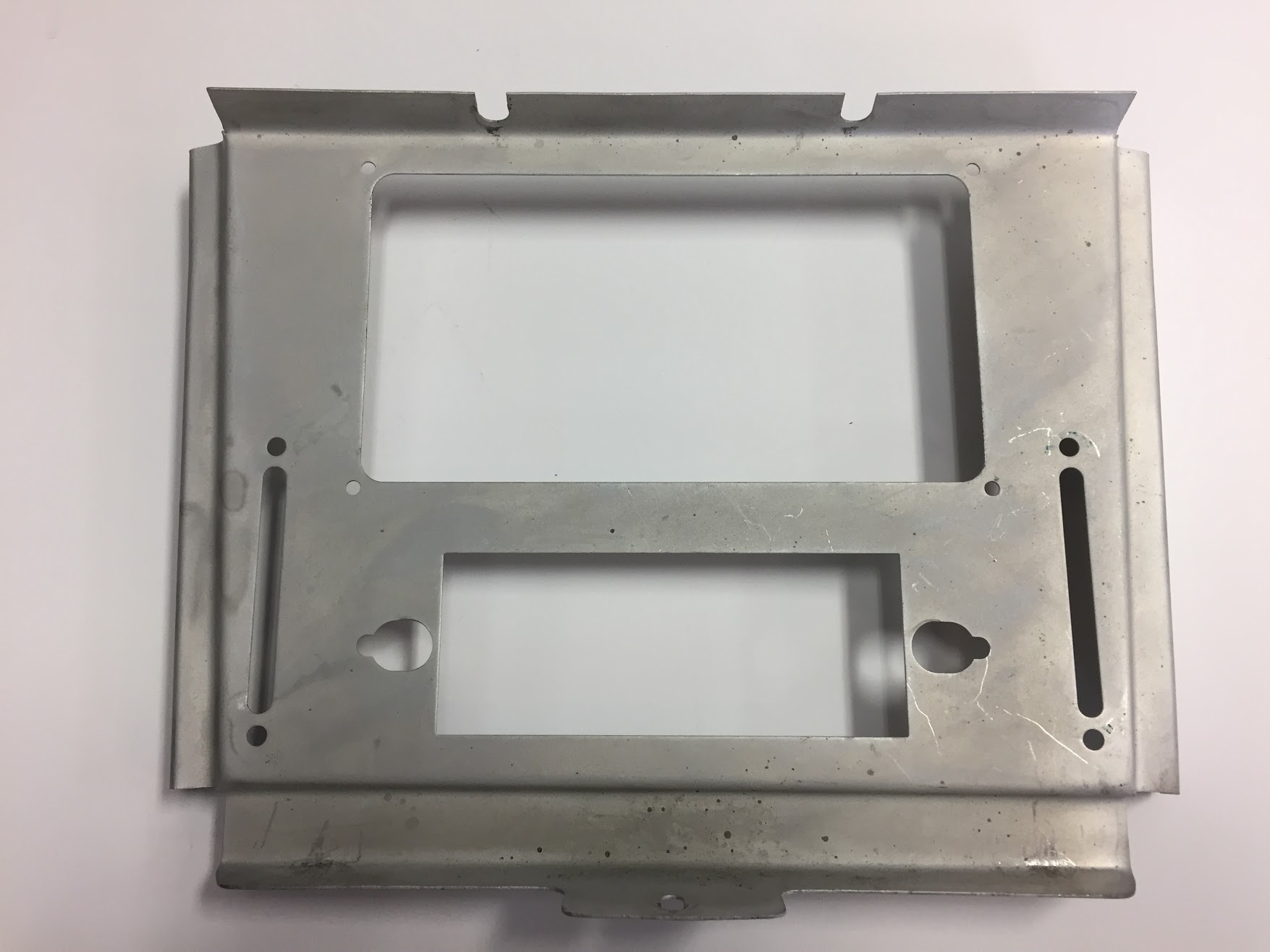
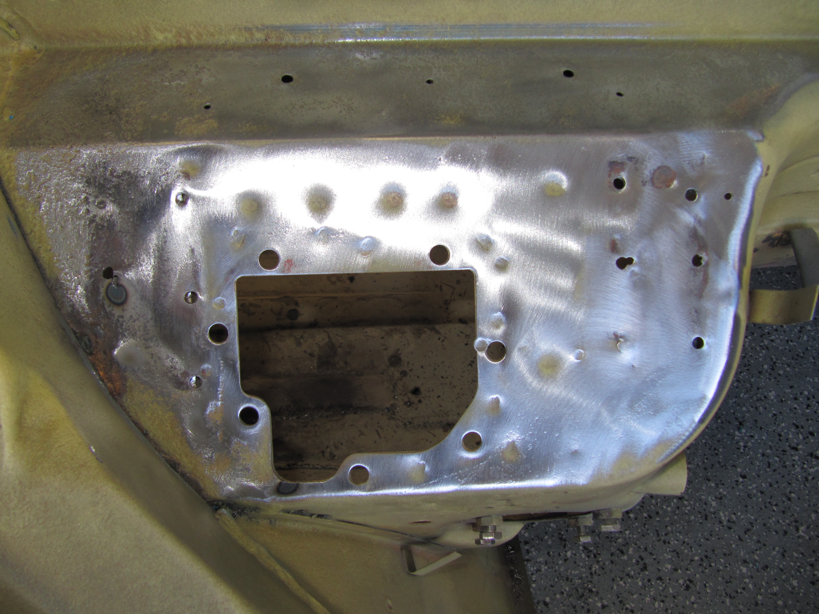
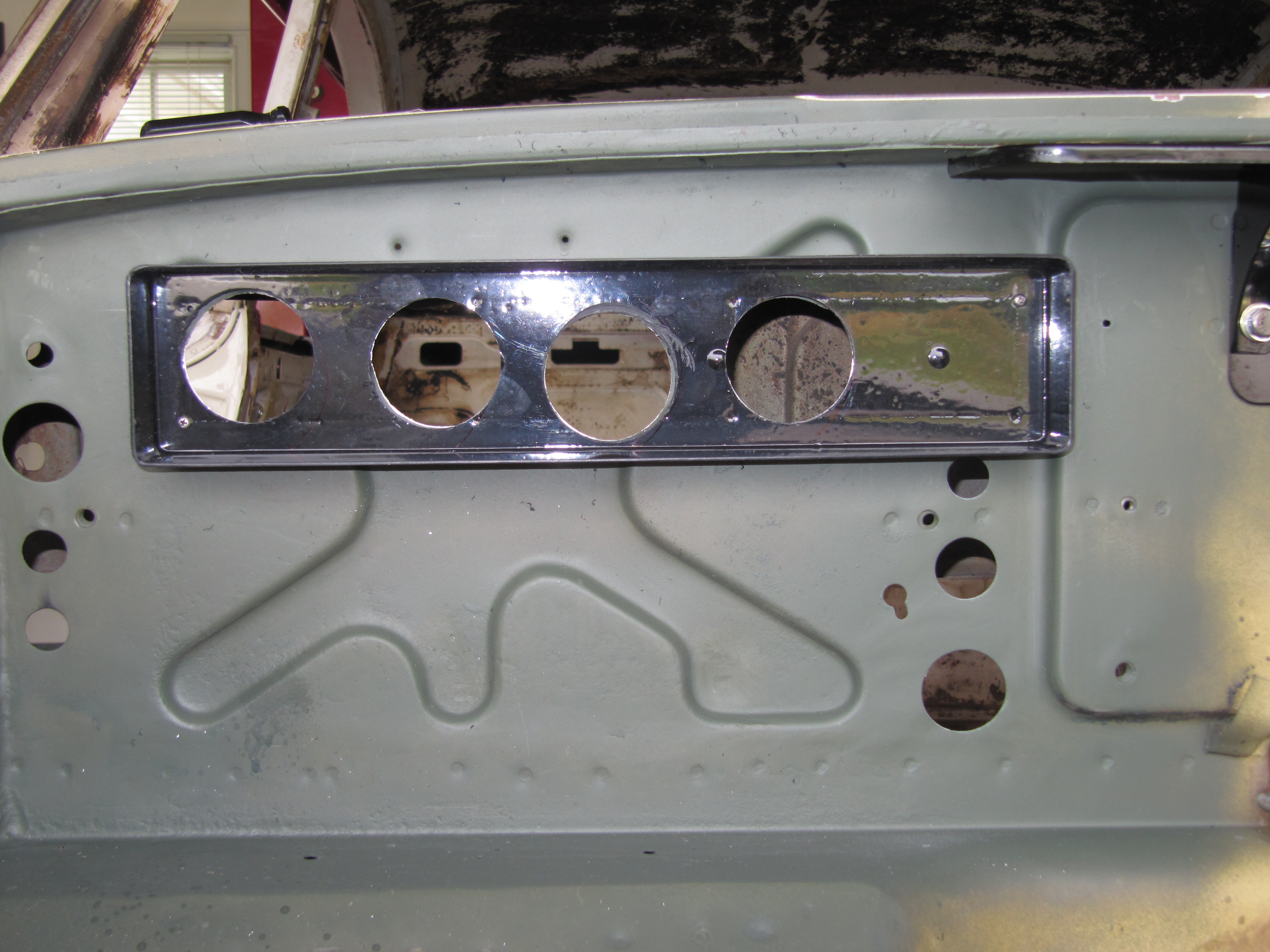
The kit supplies a Blower Reinforcement Plate. The plate was used as a template for drilling new mounting holes. To get the proper alignment a bolt is placed in the lowest (and centered) hole in the body.
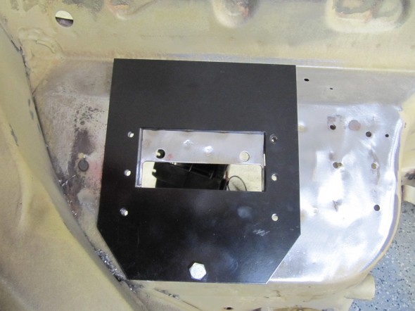
Blower Reinforcement Plate as Template. See locating bolt
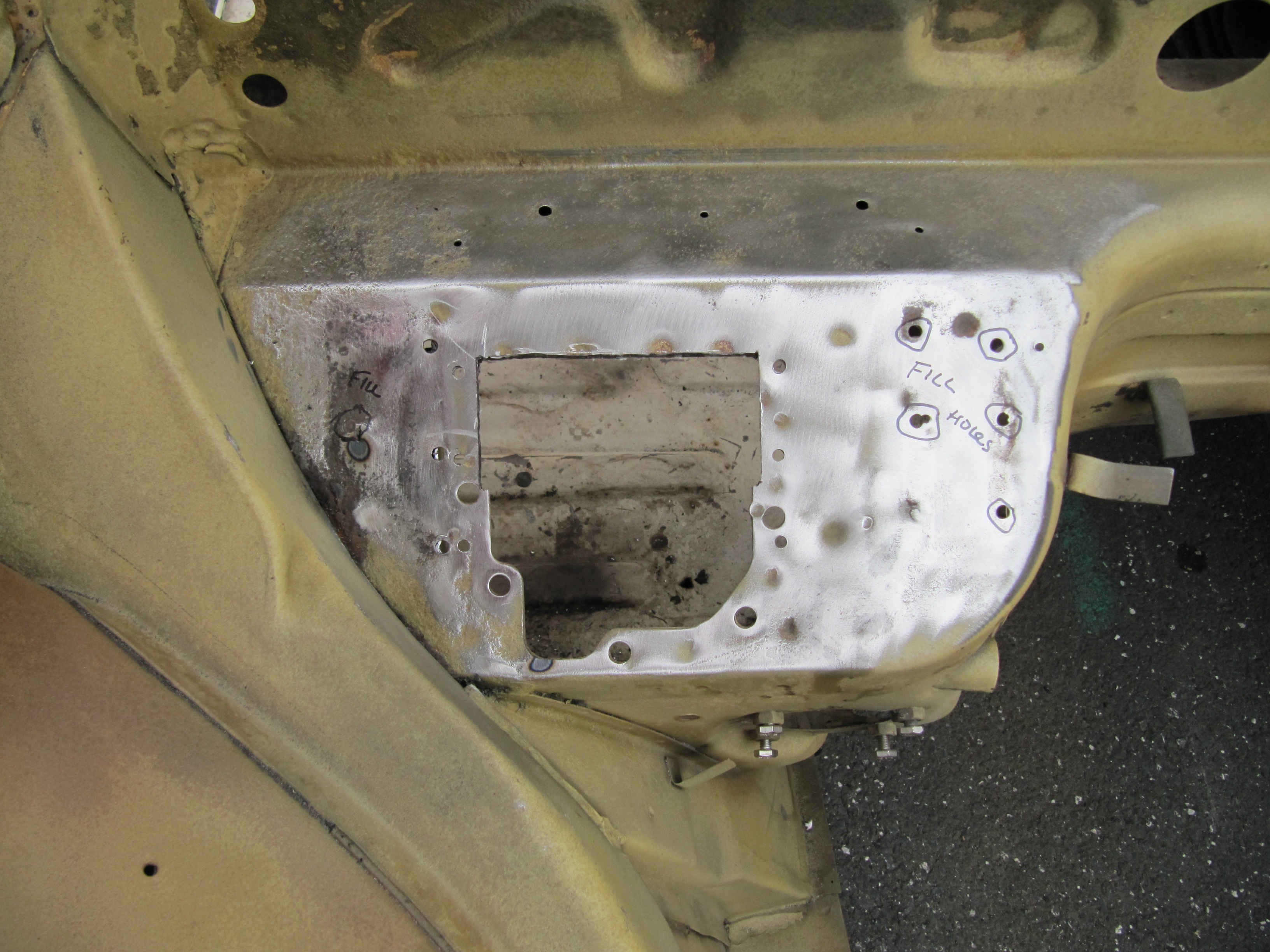
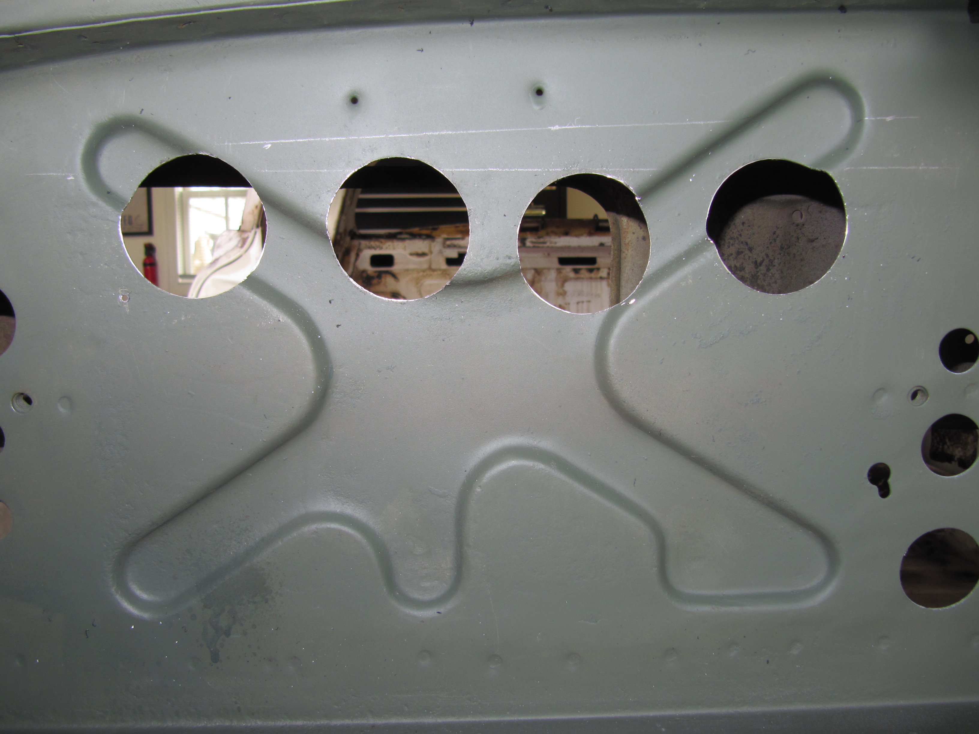
With the opening in the Blower Reinforcement Plate as a guide the body was marked for metal removal to match up with the opening in the blower that will be mounted below. This is done to ensure maximum air flow. The six holes were also marked to drill. The holes left from the battery tray braces will be welded closed.
Footbox Marked to Enlarge Opening for the Blower
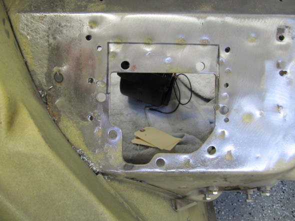
I used a dremel to remove the metal and then files the edges smooth.
Footbox Metal Removed
The ABS Plastic Oval Hose Inlet provided in the kit can then be drilled to match the holes in the Blower Reinforcement Plate – this part is mounted inside the engine compartment. I will use use Silicone sealer under the plate and Blower Mounting surface for a good seal when I do the final install after the car is painted.
Holes Welded and Area Primed
Plastic Oval Hose Inlet Mounted to the Blower Reinforcement Plate. Two additional Holes Drilled Later.
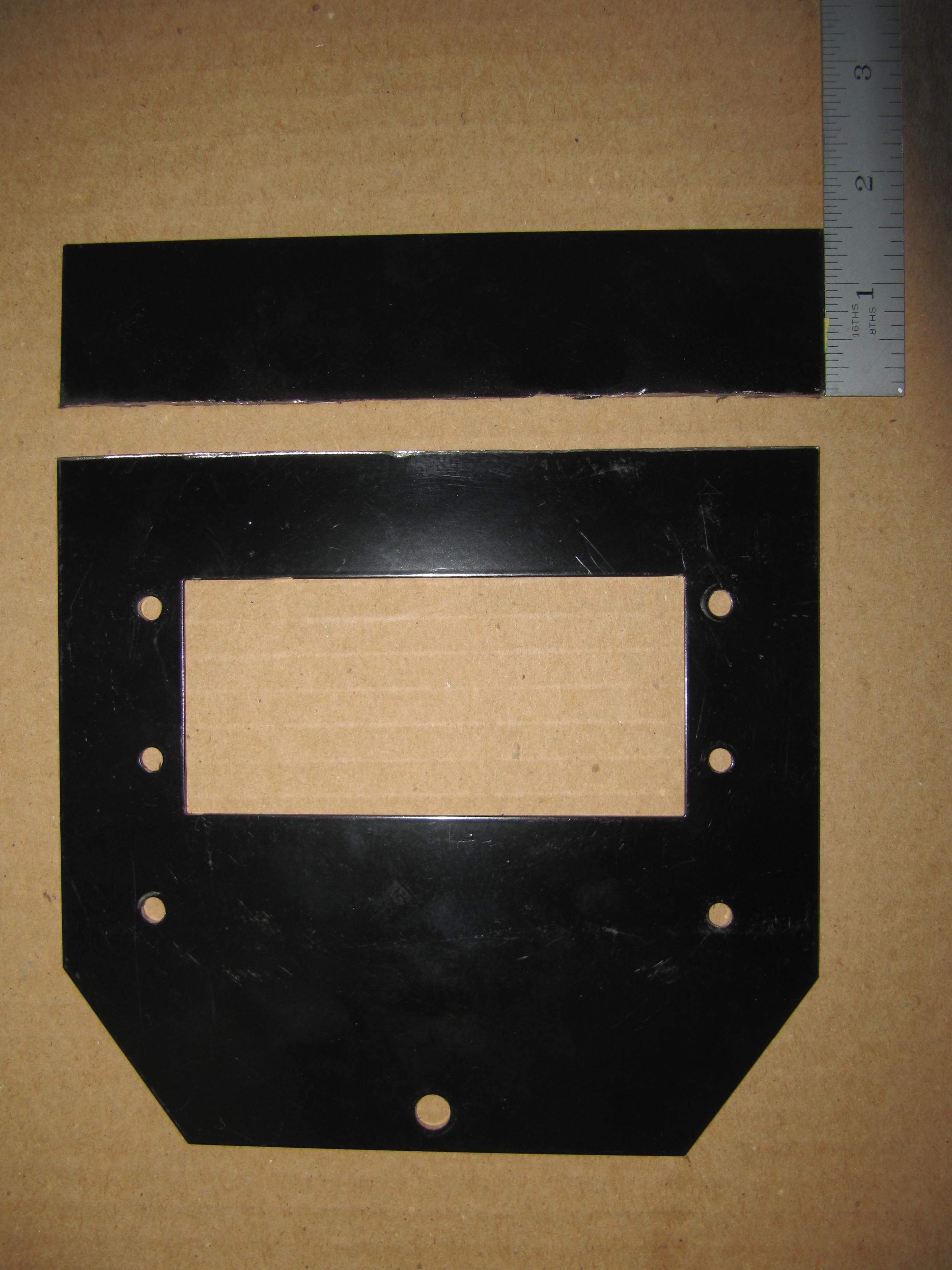
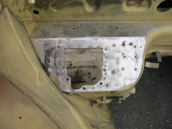
I couldn’t determine why the Mounting Plate extended beyond the Plastic Oval Inlet. I decided to remove the excess metal from the Plate and cut it off with the dremel and repainted. After final installation, the locating hole at the bottom of the Mounting Plate will have a rubber grommet installed.
Blower Reinforcement Plate Trimmed
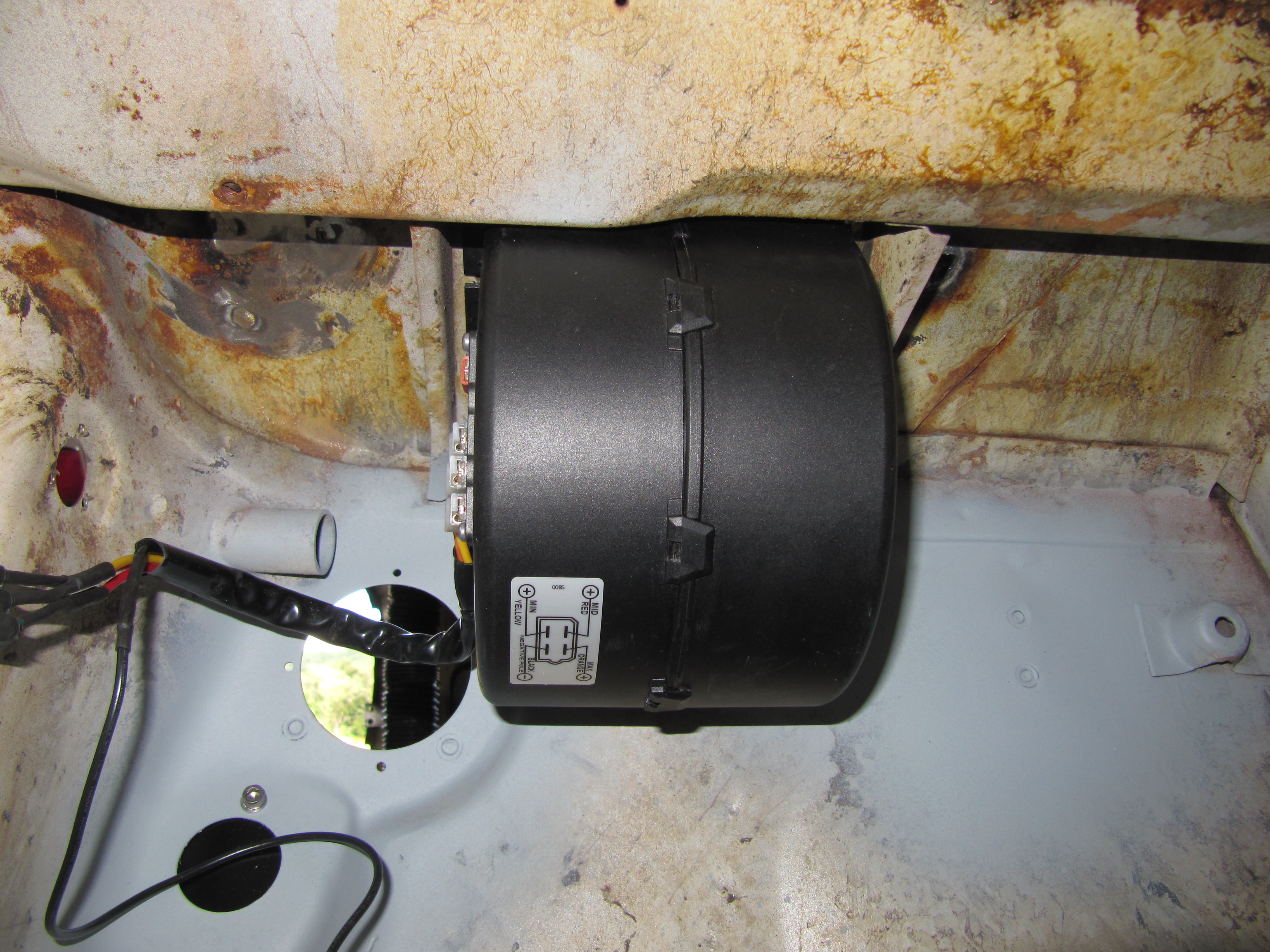
The SPAL Blower was then fit in the inside RH side of the passenger compartment. The Blower is a very tight install which is nice unless, of course, one is trying to install the Blower while standing on one’s head! Installation of the blower requires a helper. I replaced the six screws provided in the kit with six stainless #10-24 x 3/4″ phillips head screws, but used the square nuts provided as they “lock” into the spaces provided on the base of the Blower.
I had to remove the top half of the LH carpet snap mount in order to place the Blower. When I do the final installation I will seal joints and surfaces with silicone sealer.

Trimming the Carpet Snap Mounting for Blower Clearance

Blower Installed
Blower LH Mounting Screws
Blower RH Mounting Screws
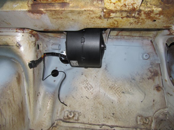
Blower Mounted in Place
Evaporator
I chose to use the evaporator provided by the RetroAir kit. Before mounting the evaporator to the firewall of the MK2, I first installed a few engine compartment components to make sure that as I fit the evaporator I did not come into conflict with other engine bay parts. As with the other air conditioning kit parts, the evaporator was much easier to mount not having the motor in the engine bay!
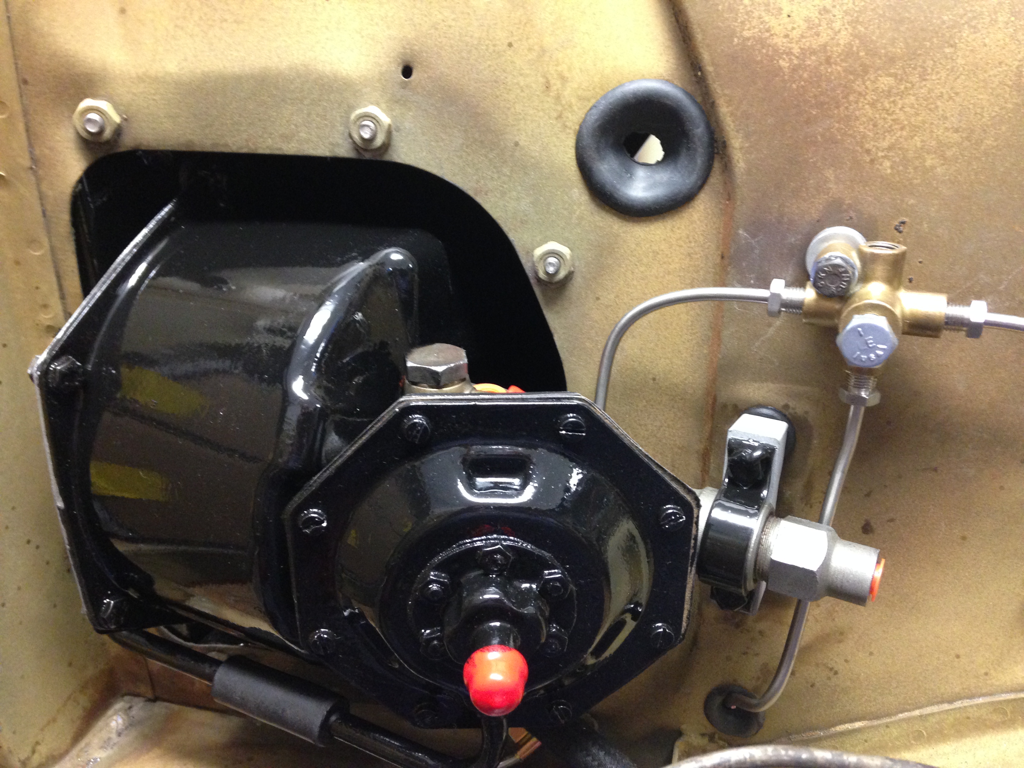
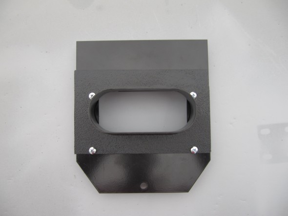
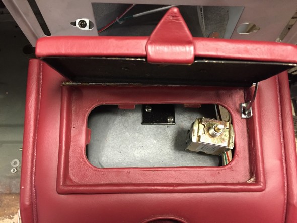
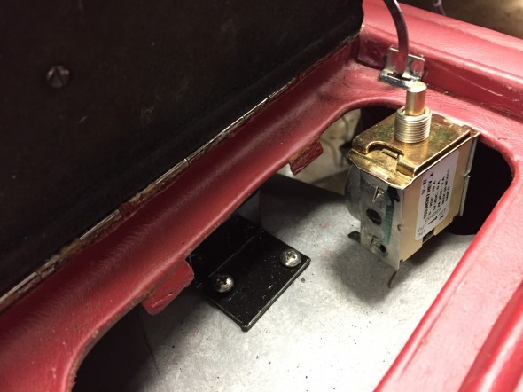
I first installed the Shield Assembly, Adapter Plate and Starter Solenoid to the firewall with three 1/4″-28 x 5/8″ hex head bolts with flat washers and shake proof washers.
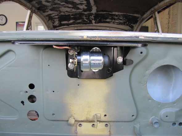
Shield Assembly, Adapter Plate and Starter solenoid
I then installed the heater pipe clip at the rear engine stabilizer bracket on the firewall. Two 3/8″-24 x 5/8″ hex head bolts with flat and shake proof washers secure the clip to the wall. Also one additional bolt and washers of same size is used through the rear engine stabilizer to the firewall.
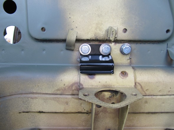
Heater Pipe Clip
Finally, I also installed the RH Bonnet Hinge as it comes close to contact with the evaporator.
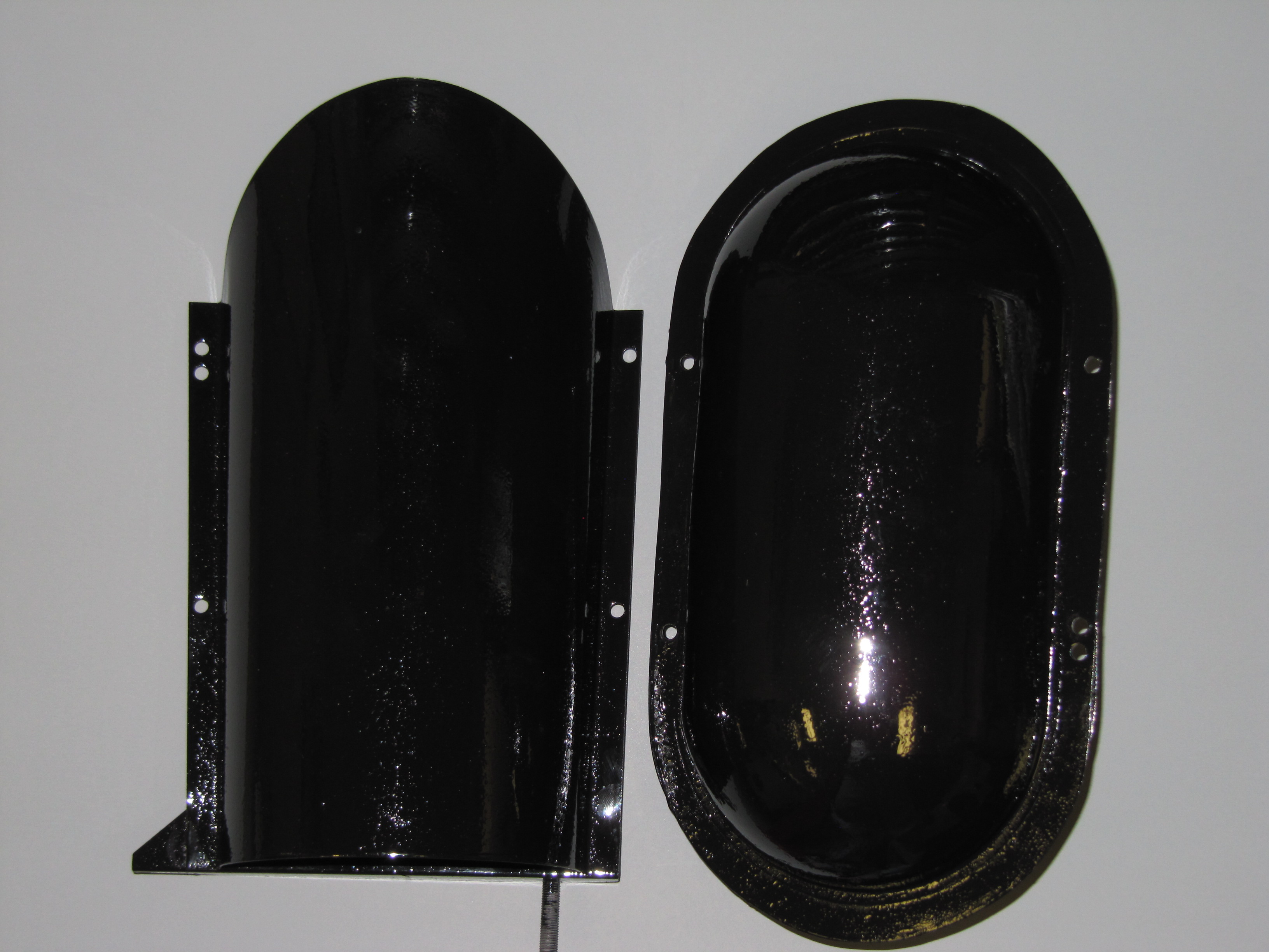
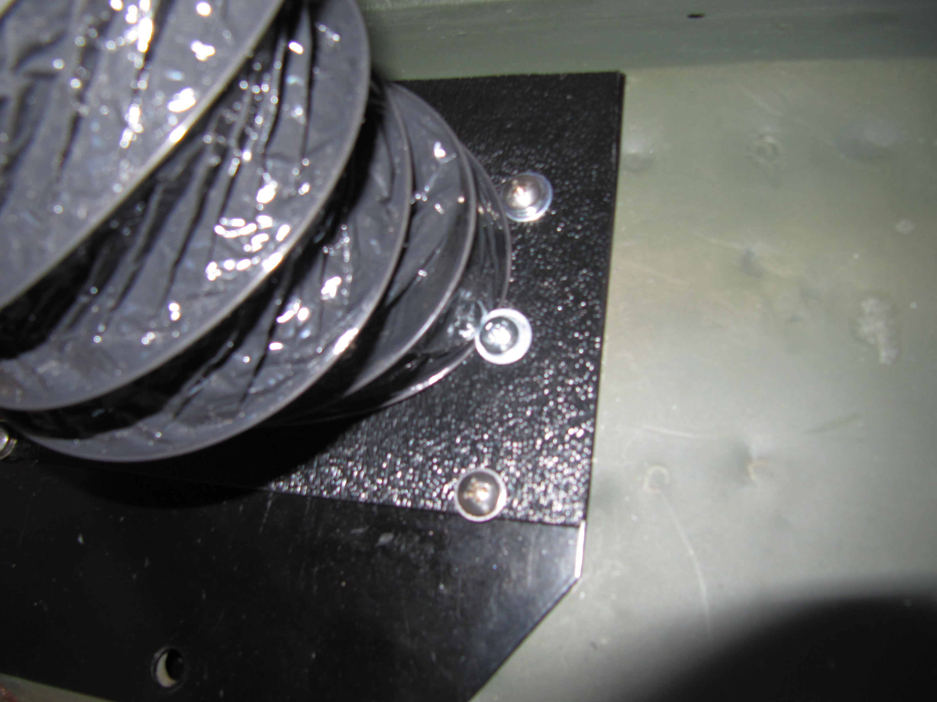
The next step is to mount the rectangular plastic cover of the evaporator to the firewall. Proper positioning is important. With the flat side of the cover away from me (I was standing in the engine bay) and the open side with the edges facing toward me, I drilled a 3/32″ hole in upper left (driver’s) side of the plastic cover and also in the lower right (passenger) side, to locate the cover to the firewall.
Then, following RetroAir’s directions, I placed the left (driver’s) side of the the plastic cover against the right (passenger’s) side edge of the center raised panel just below the starter solenoid. The directions call for the cover to be 1 1/2″ below the underside of the cowl overhang. At the far LH upper corner of the cover, I placed it about 1 5/8″ below, because I intend to make a cover for the evaporator assembly once installation is complete and I wanted to make sure that I had sufficient space to do do.
I placed a small level on the plastic cover to make sure it was level with the upper left corner 1 5/8″” below the cowl, and marked the firewall through the 3/32″ holes in the cover. I then drilled holes in the marked locations and secured the plastic cover to the firewall with two #4 1/2″ sheet metal screws. The cover established the location of the evaporator on the firewall.
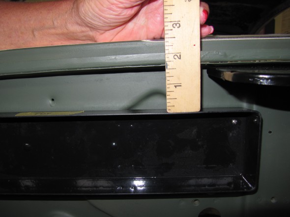
RetroAir Evaporator Plastic Cover Distance from Cowl Mounted to Firewall
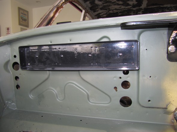
RetroAir Evaporator Plastic Cover Mounted to Firewall
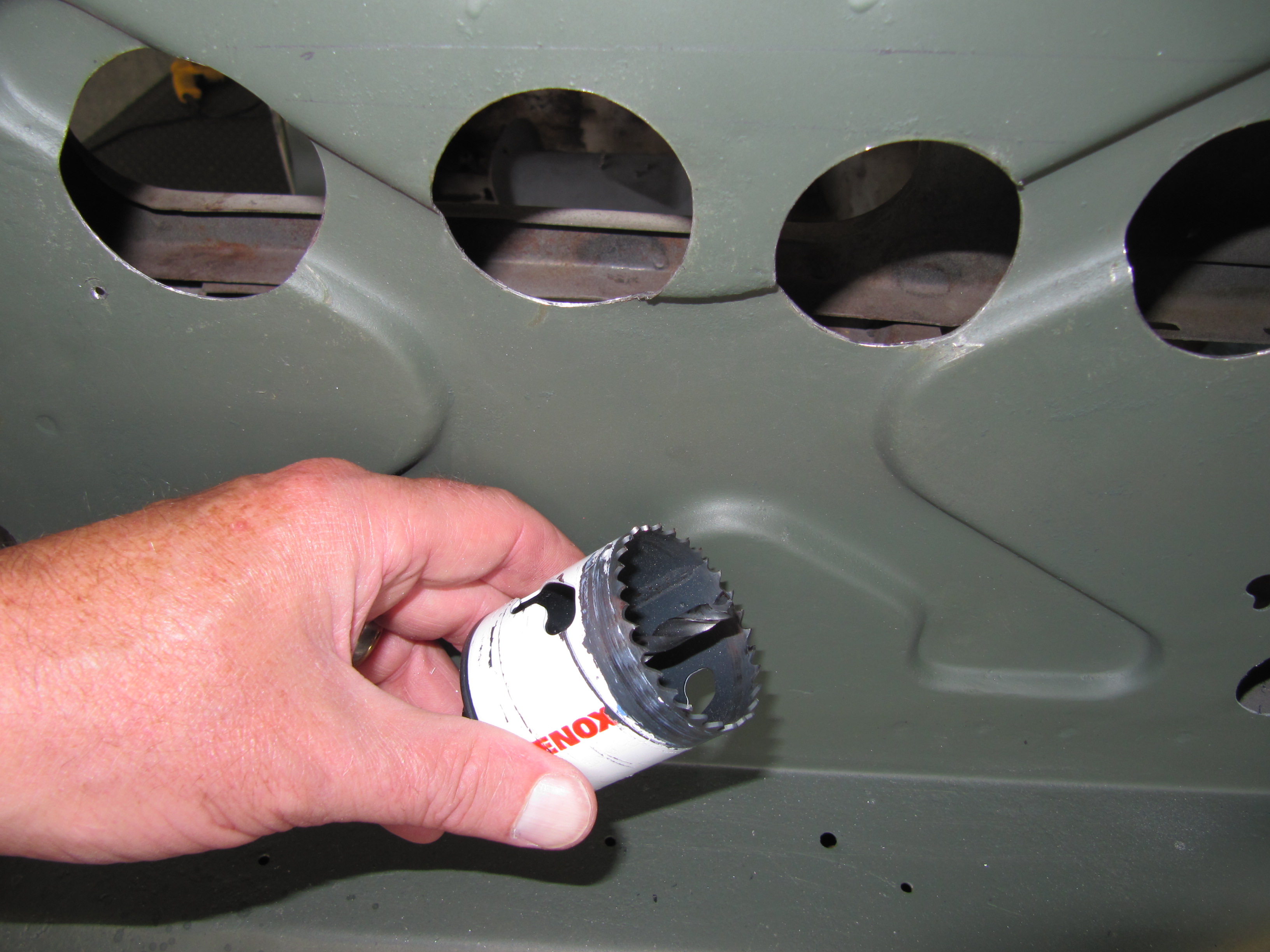
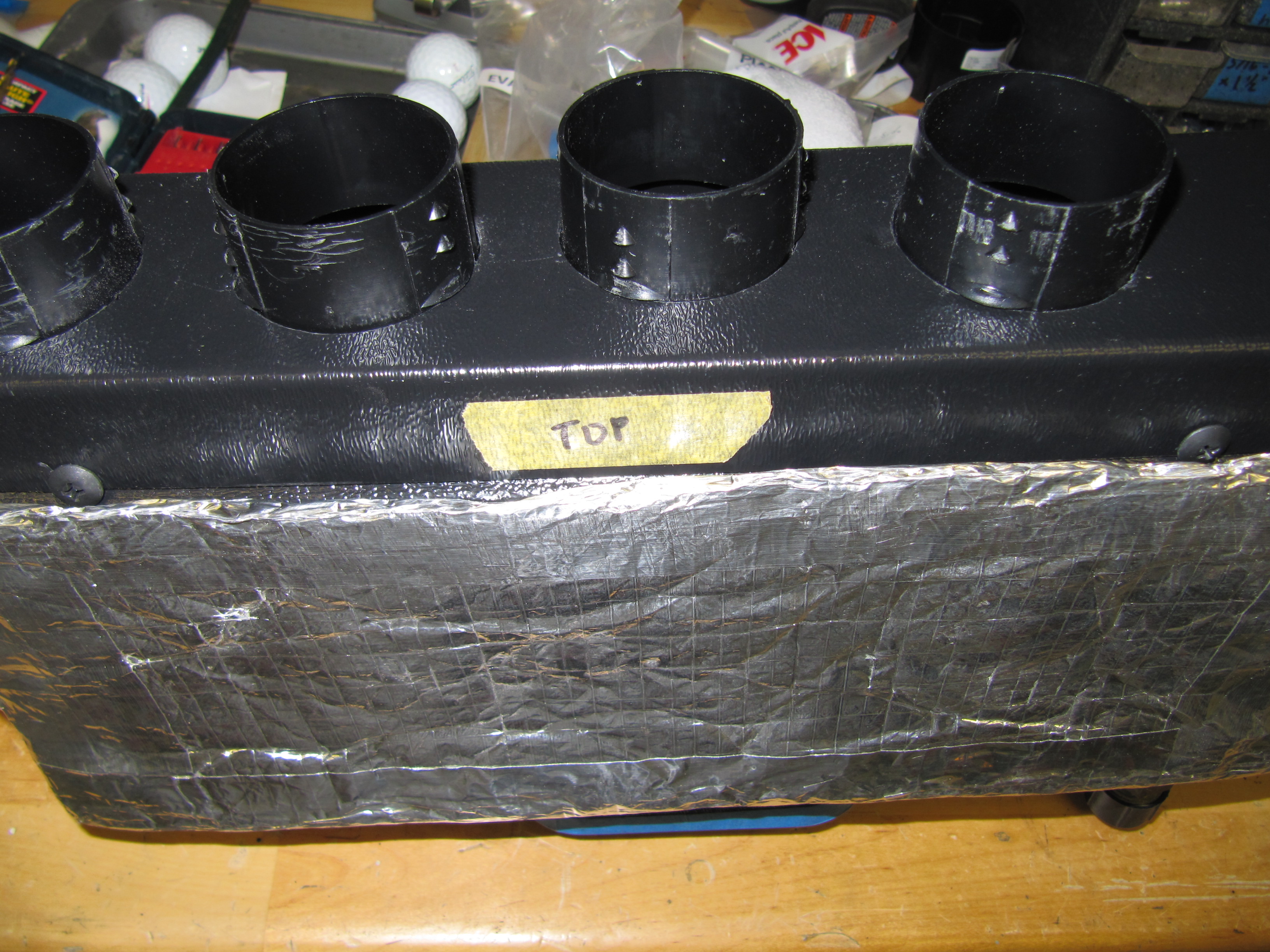
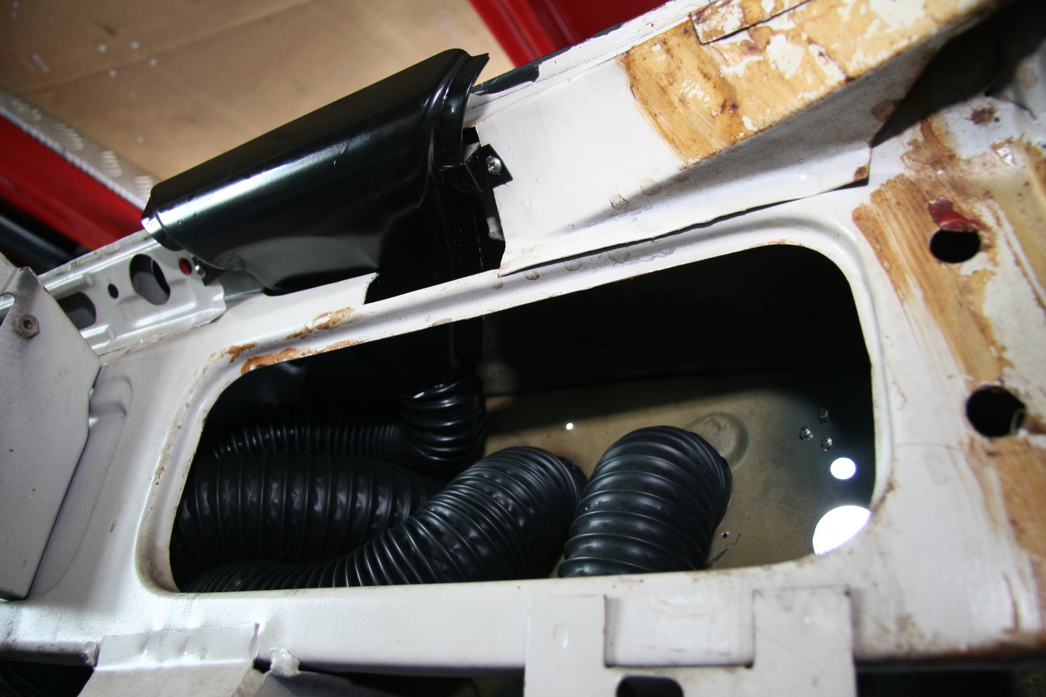
The directions then call for drilling four 2″ holes through the cover and the firewall. Before doing this there are several matters to consider: if the original demister hoses have not been removed they need to be disconnected and moved out of the way so they are not contacted by the hole saw. Mine were already removed. Also, while not specifically mentioned in the directions, I found it best to locate the holes off-center to the RH side of the cover to ensure missing the plenum behind the firewall and so as to give room for manipulating the hose after passing through the firewall.
The depressions in the firewall add a little difficulty to the drilling/sawing task. I had a little problem with the hole located third from the RH side of the cover. The central drill bit hit one of the angled depressions and slipped downward somewhat. No problem, but that hole is not in line with the others. If a reader is undertaking this project, you might want to drill small locating holes first to help avoid my problem.
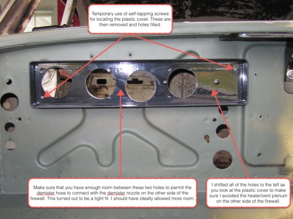
Evaporator Cover Installation

RetroAir Evaporator Plastic Cover with two inch holes for vent hoses
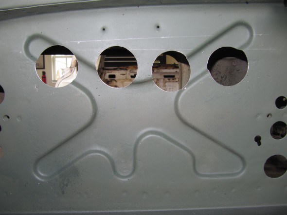
RetroAir Evaporator Hose holes for vent hoses in Firewall

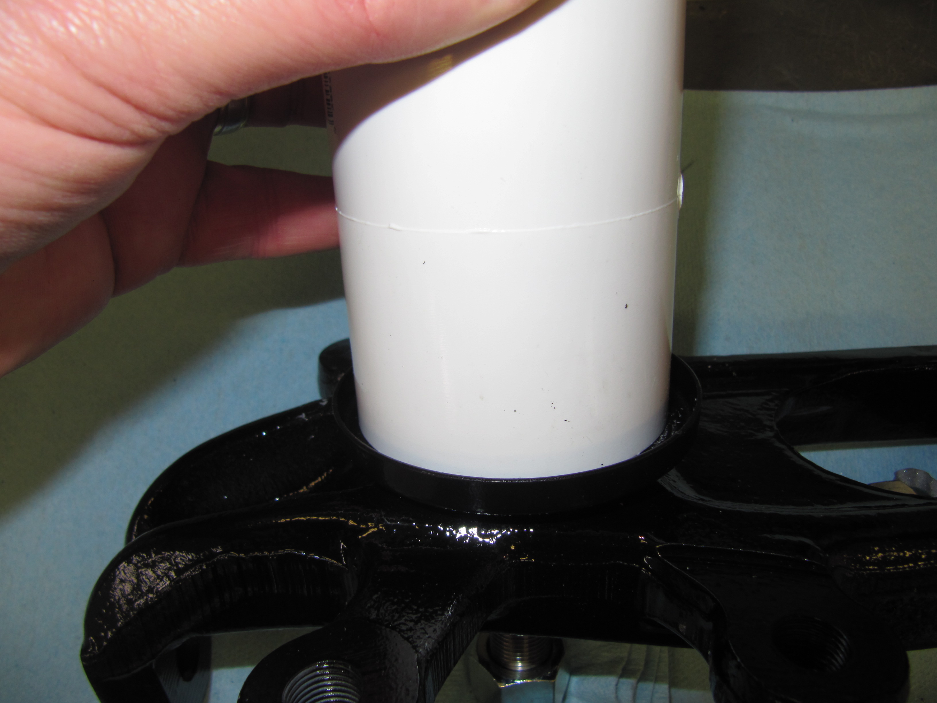
Two Inch Hole Saw
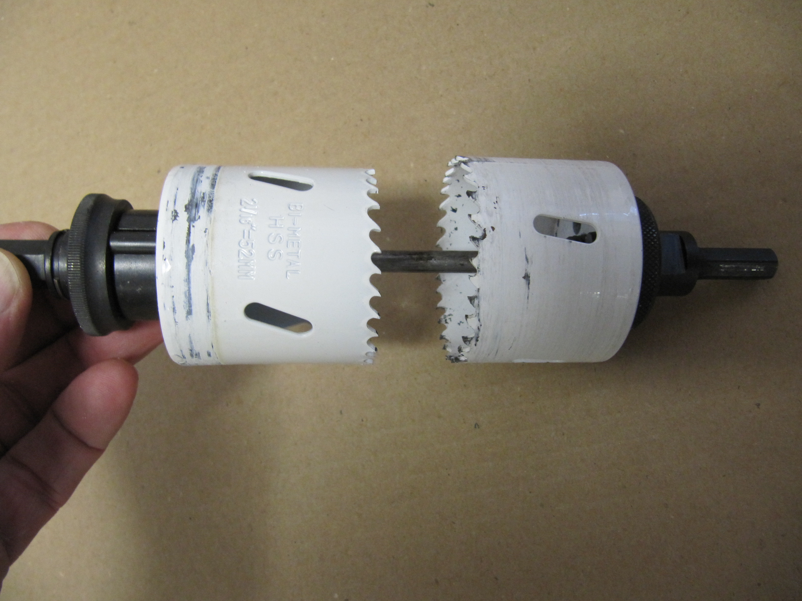
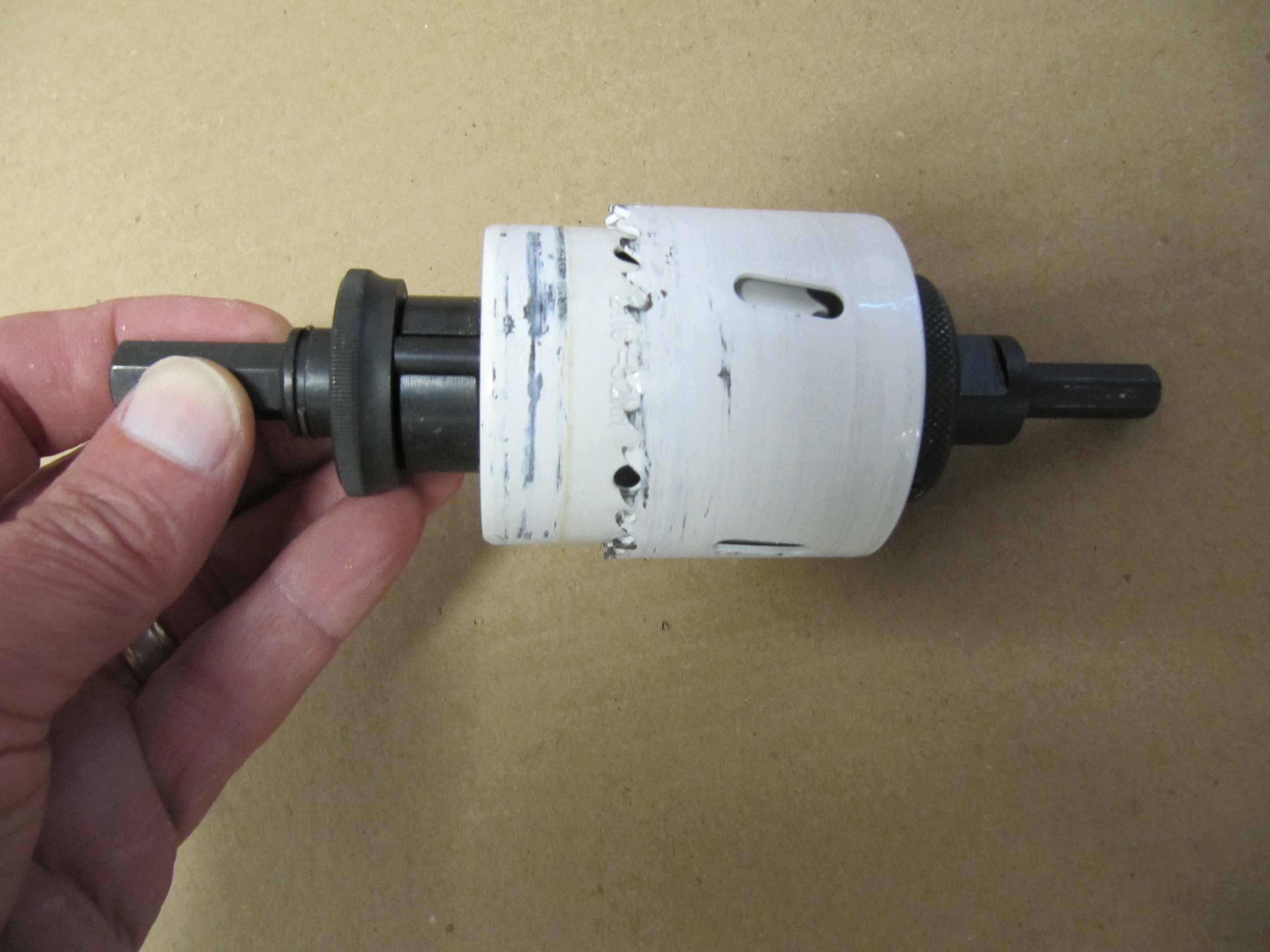
While the four plastic hose outlets would fit in the firewall holes one at a time, it was hard to imagine all four sliding into place at once when they were mounted in the plastic cover. The hoses fit over the outlets so their outside diameter is larger than the two inch holes through which they must pass. I decided to slightly enlarge each hole using a little trick the guys at my local hardware store showed me. (Sorry, don’t mean to offend but this is not the kind of tip you would get at a Home Depot or Lowes).
To drill a slightly larger hole than your original hole, you need to use the 2″ hole saw you used to drill the firewall holes as well as an additional hole saw with the larger desired hole – in this case 2 1/4″. You also need the arbor for both. First remove the drill bits used for starting the holes from each arbor and set them aside. Then cut a 1/4″ steel rod about 4″ long. Turn the 2″ hole saw so the teeth face toward the larger hole saw. Insert the 1/4″ rod into the arbors, push the hole saws together, and tighten the 1/4″ rod with the arbor set screws. Then put the 2 1/4″ hole saw arbor in your drill and you are ready to make a new larger hole! The smaller 2″ hole saw acts as your centering device for the new larger hole.

Two hole saws and 1/4″ linking rod
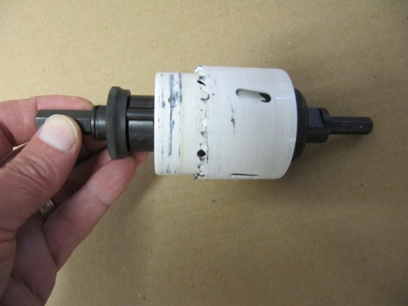
Two hole saws and 1/4″ linking rod joined together
The hose now passes through the firewall hoses without binding but still leaves a reasonably tight fit.
Each hose outlet was then popped into place and sealed with black silicone sealer.
Silicone Sealer around hose outlets
The plastic cover could then be pushed onto the end of the evaporator. RetroAir directions warn ” Do not invert cover or holes will not line up!” The two 3/32″ locating holes were also sealed with silicone sealer. Before I finally mount the evaporator to the car, that is, after the car is painted, I will fill the firewall depressions with the kit provided weather stripping to also seal the depressions.
The cover is then pushed onto the evaporator, and once tightly in place six black 1/2″ self-tapping screws provided in the kit were used to mount the cover to the evaporator. One on each narrow end, and two on each long side as seen in the image below:
Cover screws to evaporator
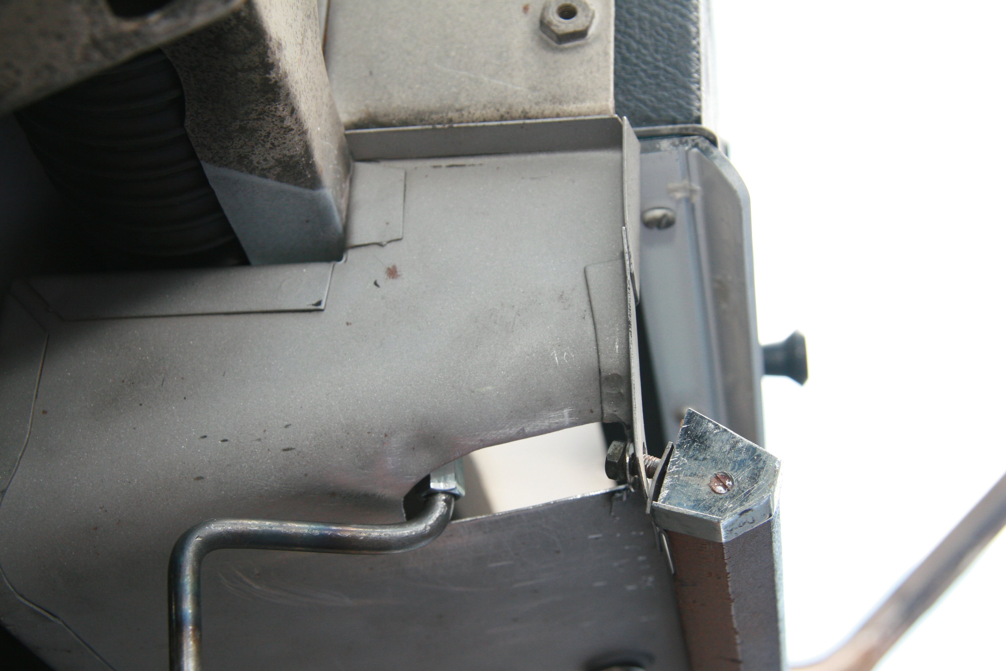
The evaporator assembly is then held FIRMLY AGAINST the firewall and mounted using the two supplied brackets. Each bracket has a 1/4″ x 1/2″ hex bolt and flat washer that is used to secure the bracket to the side of the evaporator. The brackets are slotted to be adjustable because the LH bracket needs to be shorter than the RH bracket due to the “bump out” in the center panel of the firewall (see image).
After inserting the outlets through the firewall and tightly holding the LEVEL assembly against the firewall, I drilled three 3/32″ holes in the firewall for the matching three holes in each bracket. Rather than using the kit supplied self tapping screws that looked out of place (my opinion) in the engine bay, I used #10 1/2″ self tapping stainless round head phillips head screws. The evaporator was then firmly mounted against the firewall.
LH Evaporator Mounting Bracket
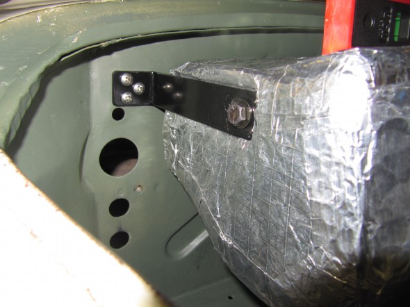
RH Evaporator Mounting Bracket
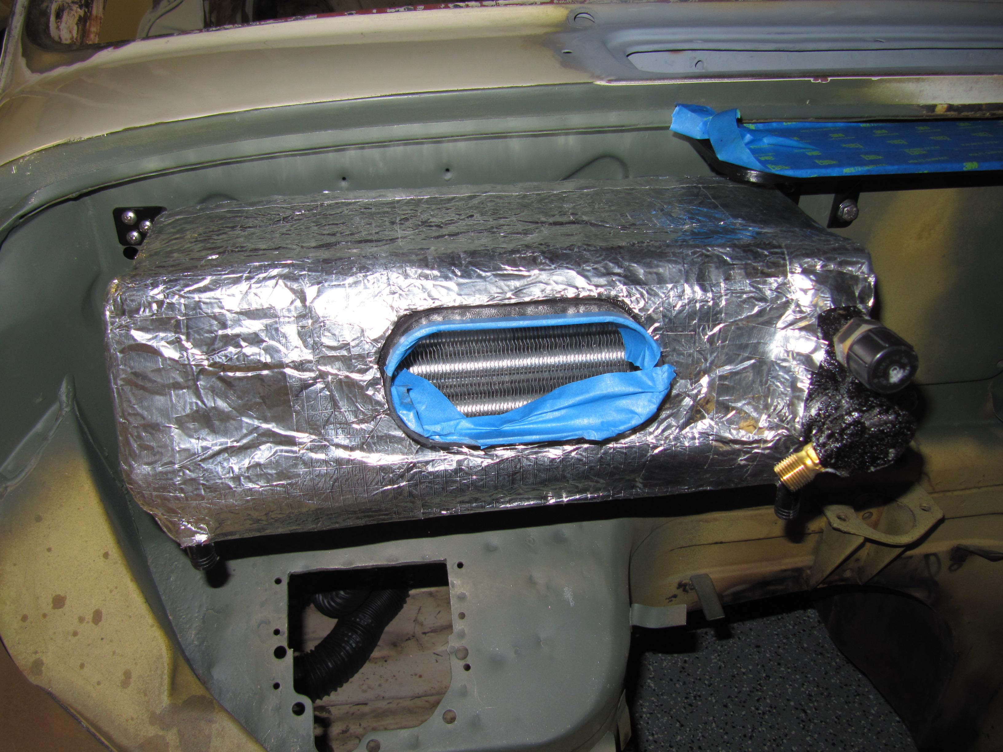
Evaporator Mounted to Firewall
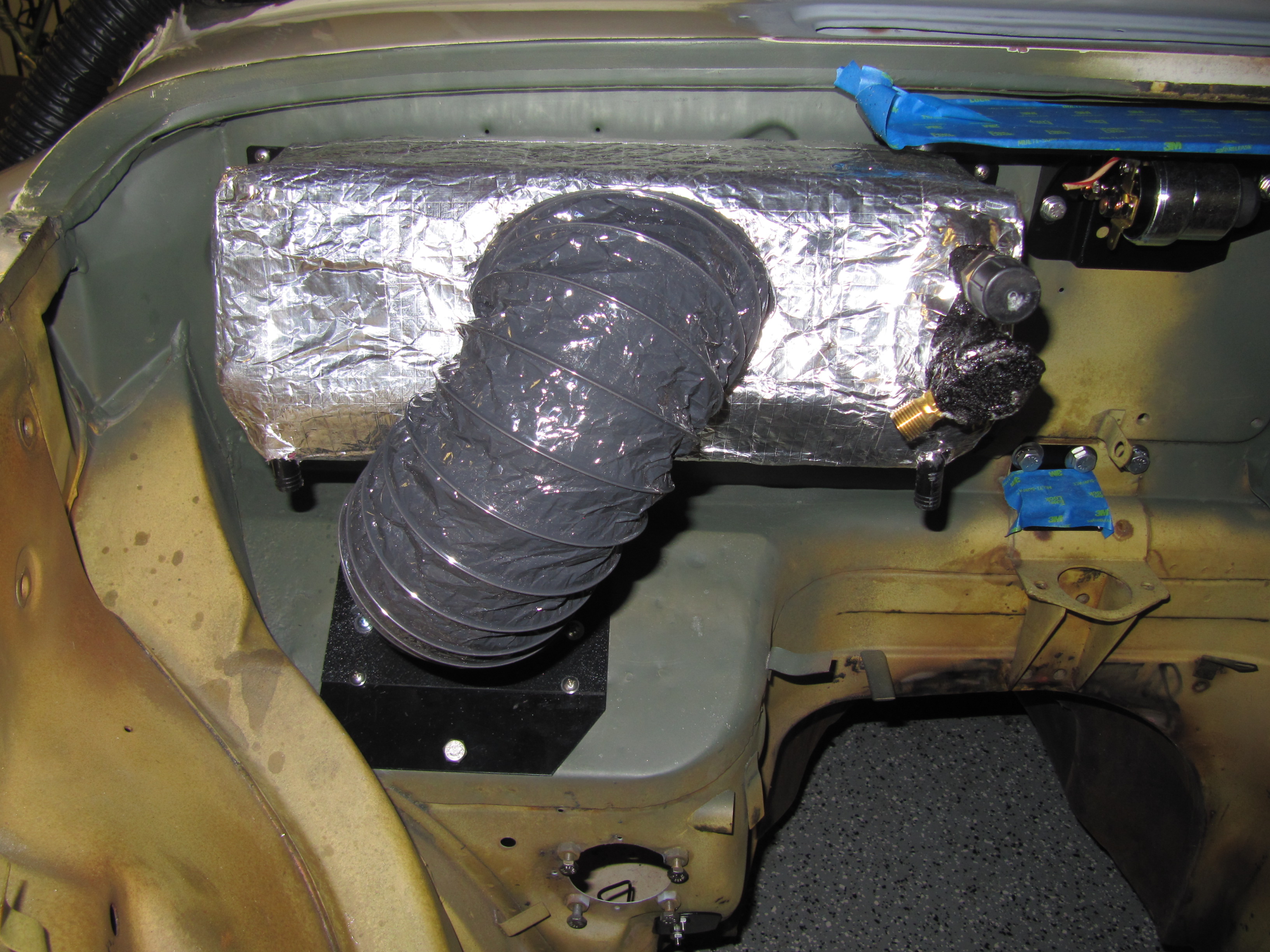
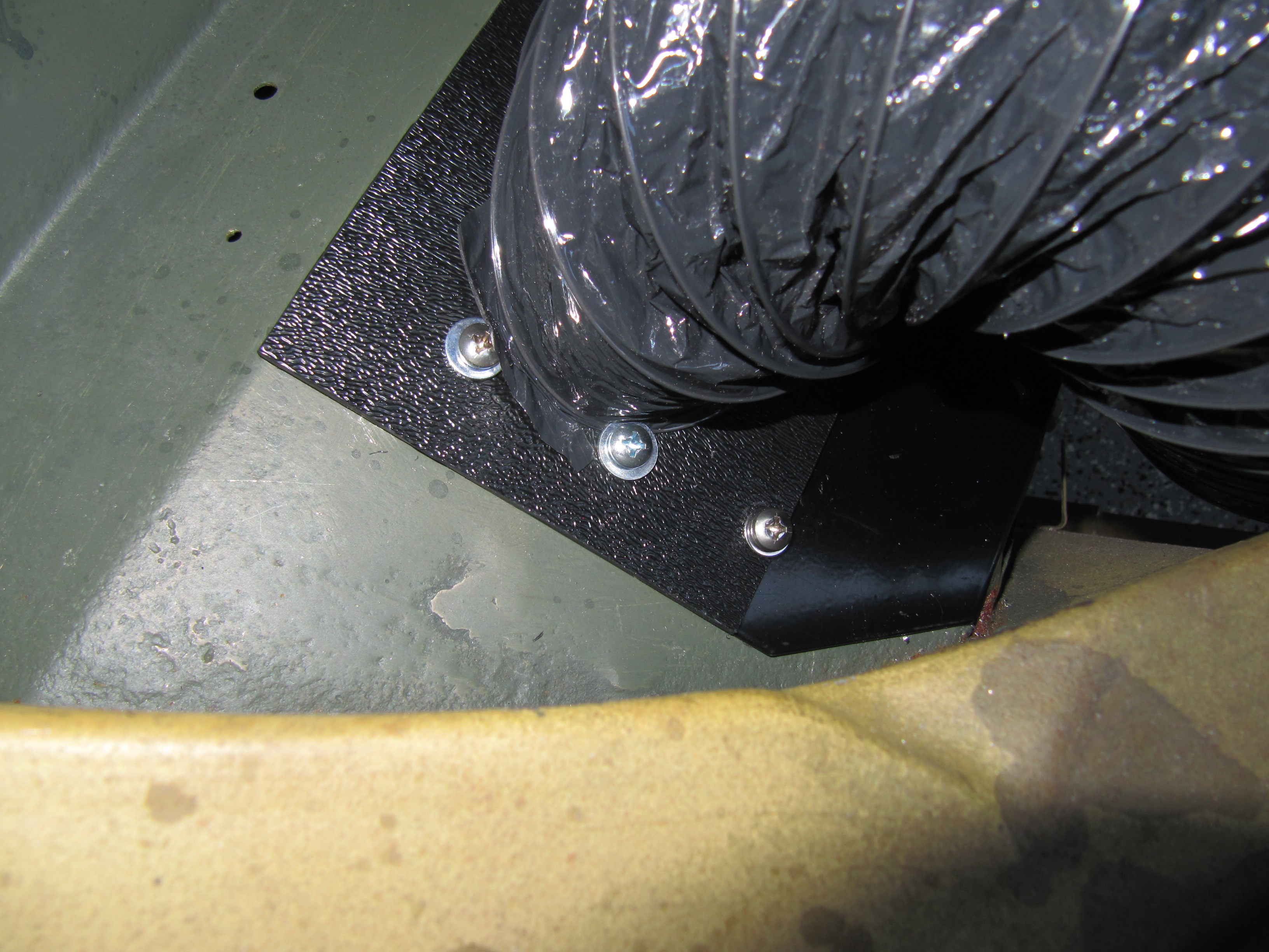
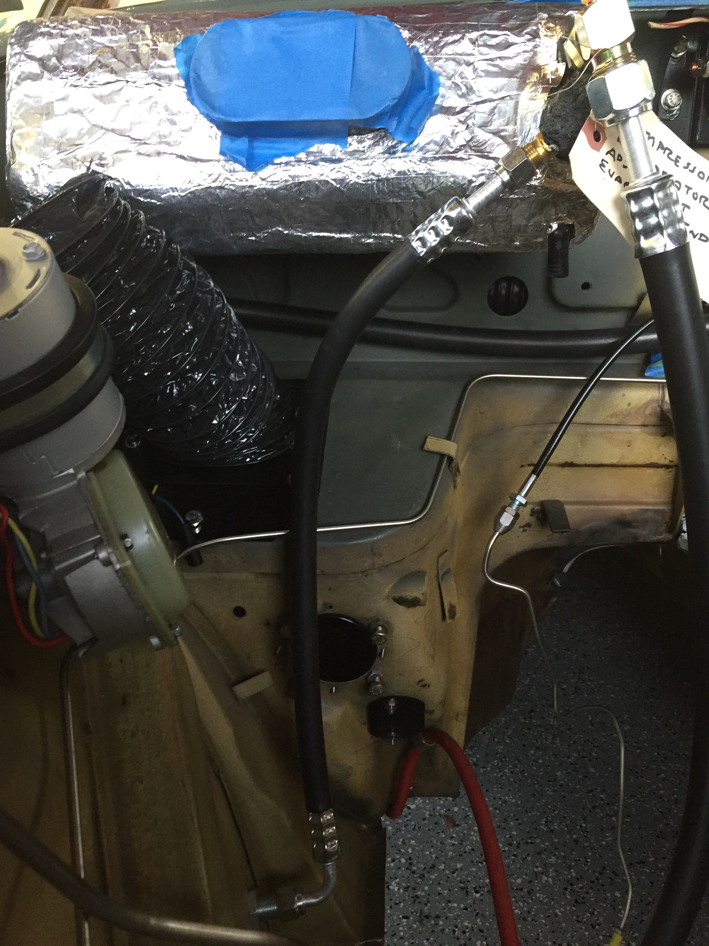
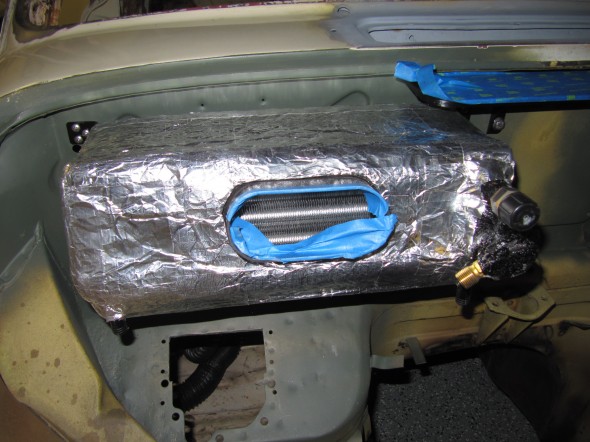
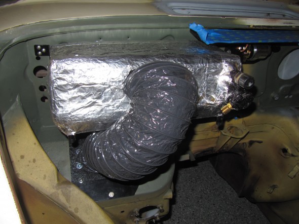
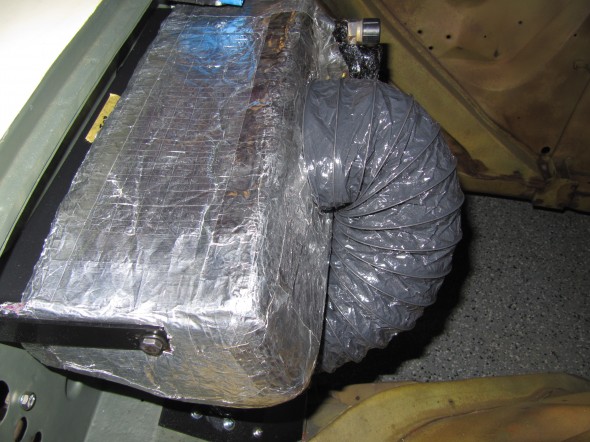
I then mounted the blower and the evaporator as an assembly and attached the flexible “inside” mylar hose to the Blower Oval Hose Inlet. The washers on two of the mounting plate screws were used to “trap” the wire in the mylar hose. I then also added a plastic tie wrap strip to secure the hose tightly to the Hose Inlet. I will also add silicone around the inlet/hose upon final installation.
I then trial fit the mylar hose to the evaporator inlet, but I will back up and install the outer insulation for the hose before attaching the hose to the evaporator. The mylar hose cannot withstand the high heat of the engine bay without insulation. I may fabricate an insulated fiberglass tube/duct to replace the mylar before the project is completed.

Mylar Hose Attached to Blower and Evaporator
Mylar Hose Wire Under Washer
Mylar Hose Wire Under Washer
Assembly Mounted
Assembly Mounted
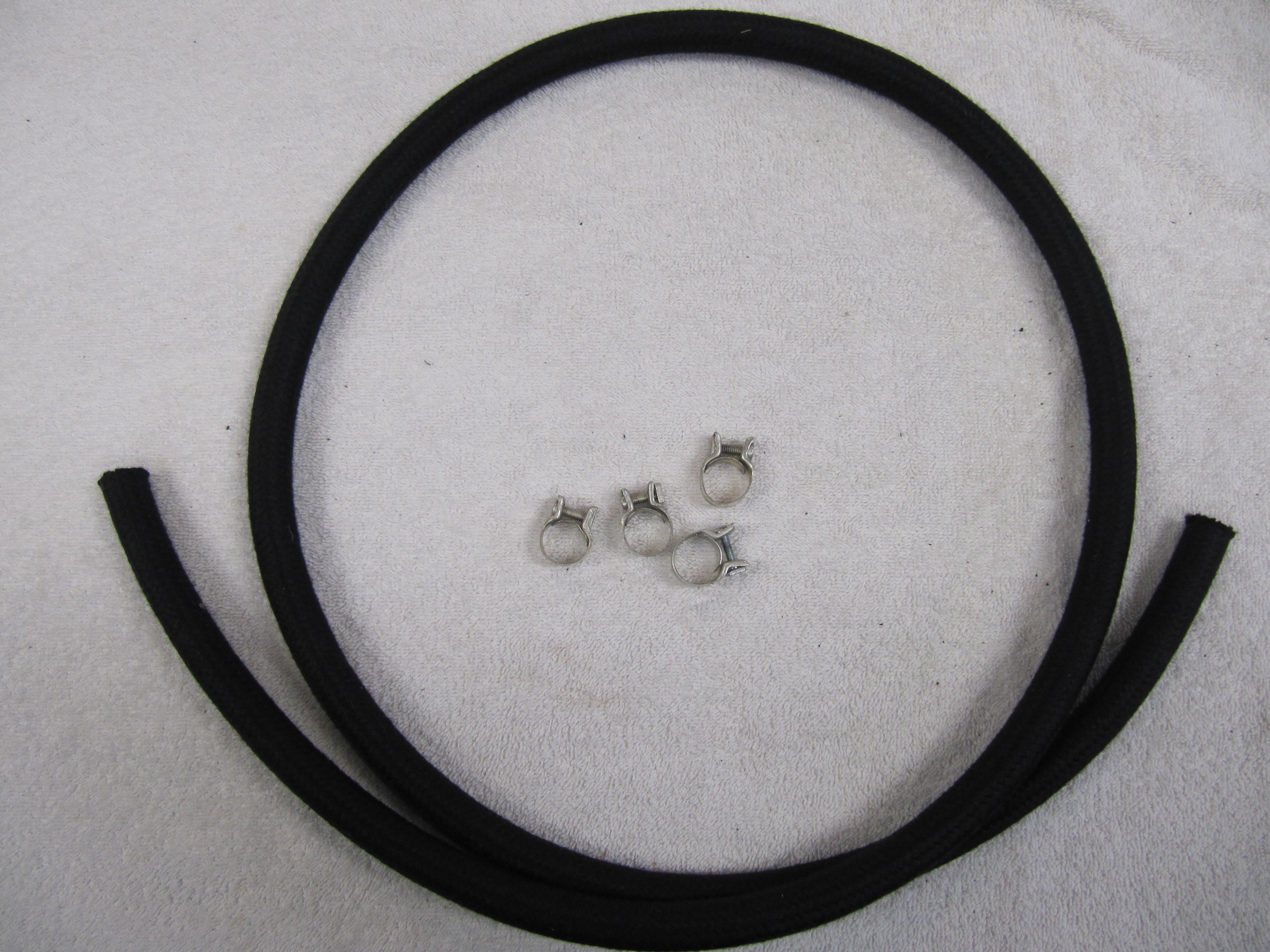
The evaporator has two right angle 1/2″ drain pipes at the front of the evaporator on the left and right outside corners. The RetroAir kit provides two pieces of drain hose to fix to these drain pipes, but they are only about 8-10″ long and unless you want water running down the inside of the engine bay valance or firewall one needs to order more drain hose.
Evaporator Drain Hose
I got six feet from Vintage Air and that enabled me to extend the drain hoses to below the chassis.
I also found that the LH right angle drain pipe path conflicted with the intake manifold in my installation. That meant cutting off and carefully drilling out the original pipe, ordering a new one from Vintage Air, and then gluing it with ABS glue (also available from Vintage Air) to the evaporator so that it exits at a 45 degree angle. These modifications worked just fine and you can see the result in the image below:
Modified Evaporator Drain Line
Vents and Air Ducting
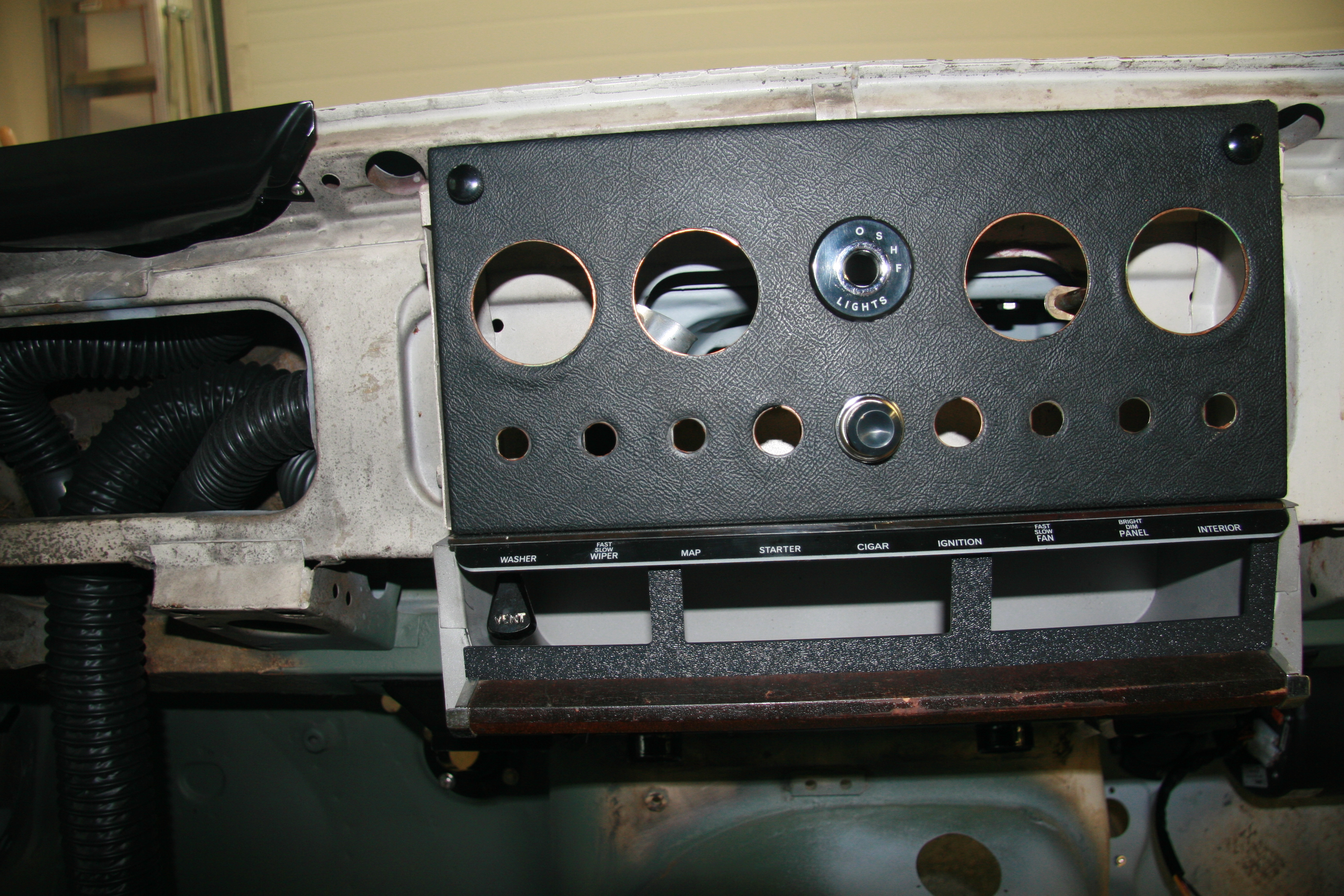
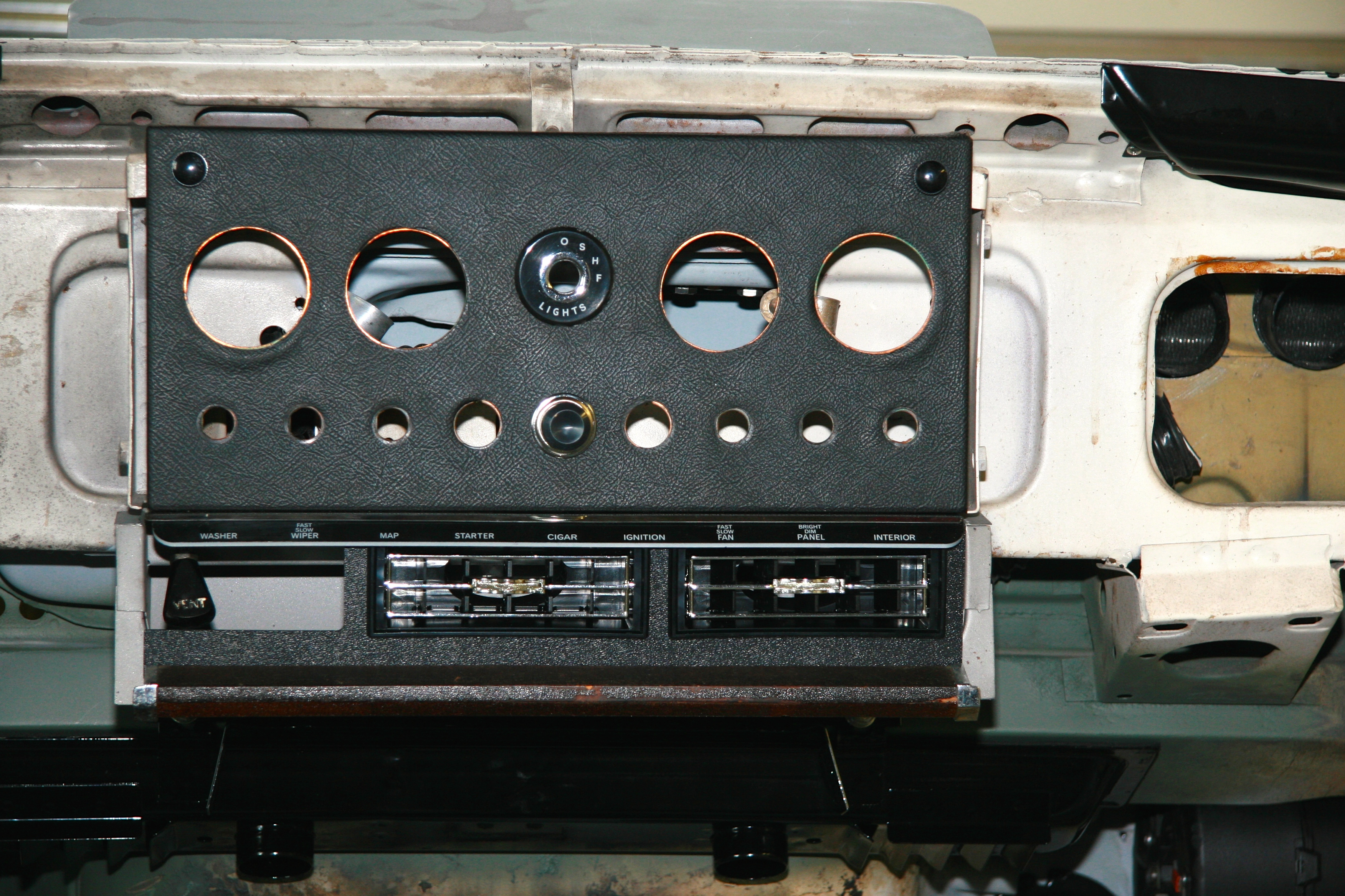
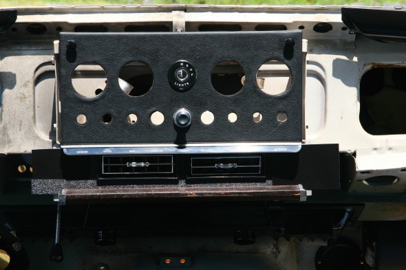
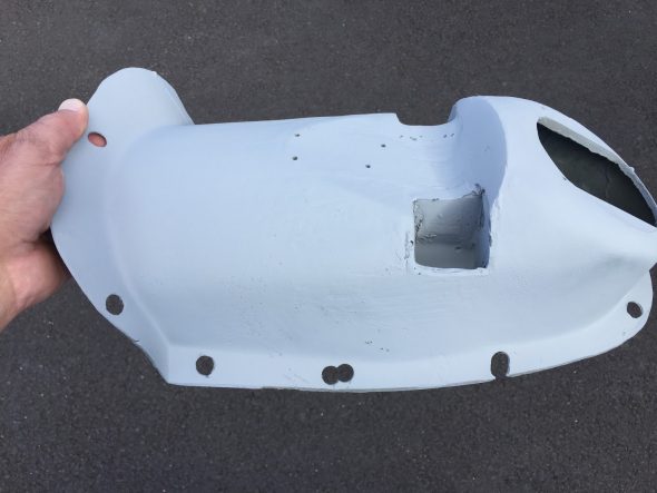
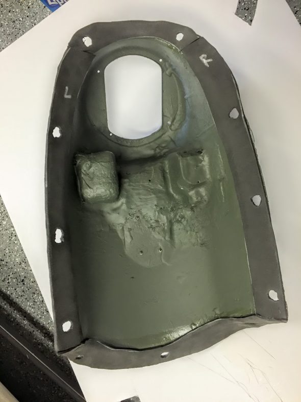
All of the initial trial fitting was done without the vent hoses or ducting attached to the evaporator. It was now time to address the installation of the hoses. This process includes the modification of the newspaper tray which the RetroAir directions improperly refer to as “the cubby.” There are four hoses in the system. One hose attaches to a provided black round vent louver to be installed on the panel below the steering wheel. Two hoses attach to the two provided rectangular vent louvers that fit in the modified newspaper tray, and the final hose attaches to another provided black round vent louver to be installed below the dash glove box, or “Cubby.”
On my car, the LH Scuttle Top Casing Assembly, is a formed aluminum panel that will be modified to accept the vent louver. The RH Scuttle Top Casing Assembly is some type of flexible fiberboard. I have not yet decided upon a final strategy, but I will probably fabricate a panel for the RH side similar to that provided by Jaguar on the LH side. Two and one-half inch holes will be cut into both Casing Panels for the round louvers. Consideration will need to be given to the shape of the RH Casing Assembly to permit sufficient air to access the blower motor.
Modification of the Newspaper Tray
This installation will no longer permit the tilting of the instrument panel on its hinges. With the louver panel in place movement is restricted. To gain access it will be necessary to remove the front edge wood capping and the louvre panel and the stretch the duct hose to get behind the instrument panel.
This is another place where I departed from the provided directions. The louvers located in the newspaper tray are mounted in a black grained plastic fascia panel. This panel is “pinched” between the wood capping assembly at the front edge of newspaper tray and the indicator strip at the bottom of the instrument panel. As can be seen in the two images below, the vent louvres are off center to the right to provide for access to the scuttle ventilator lever knob. One has to have access to this lever to open and close the scuttle ventilator lid.
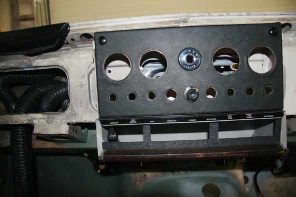
Newspaper Tray Vent Louvers Off-Center

Newspaper Tray Vent Louvers Off-Center
I did not care for the off-center look of the RetroAir approach, so:
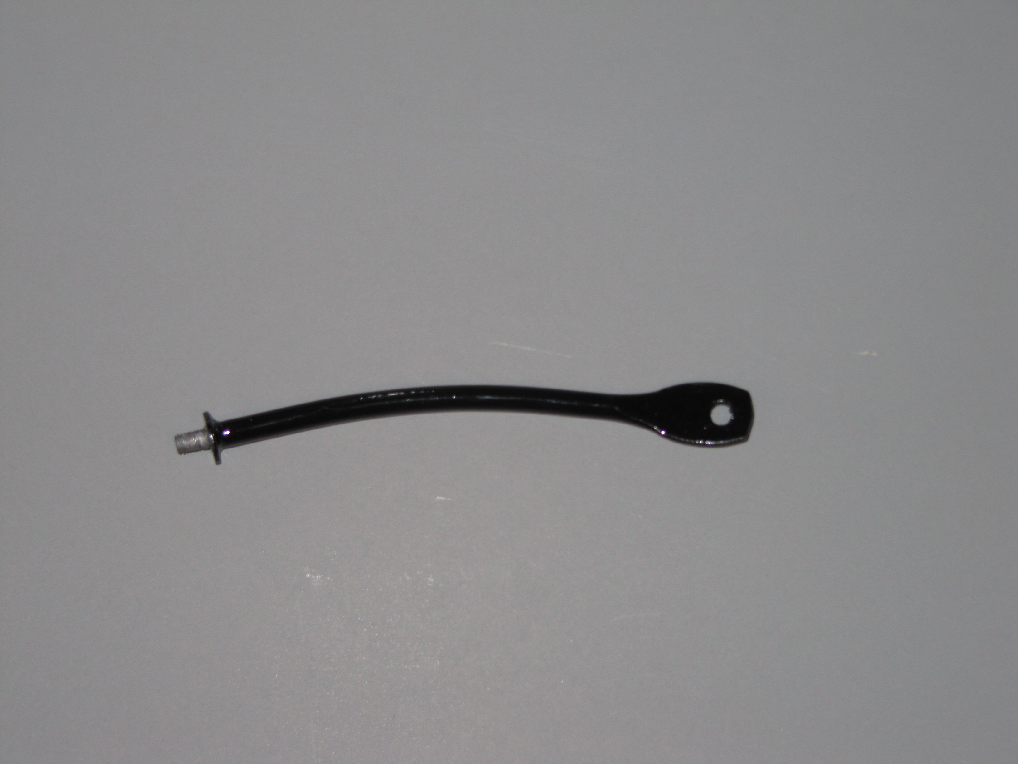
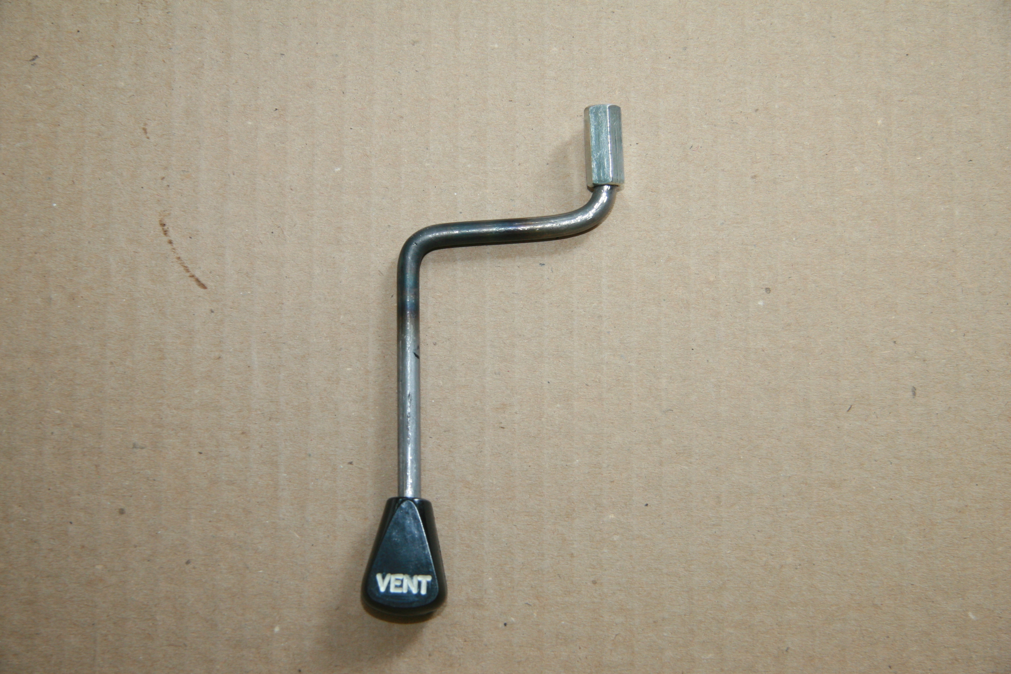
I bent and threaded both ends of a 1/4″ rod to extend the scuttle ventilator lever, then cut a slot in the LH front bottom of the newspaper tray, and finally used a 1/4″ – 20 coupler to attach the extension rod to the original lever
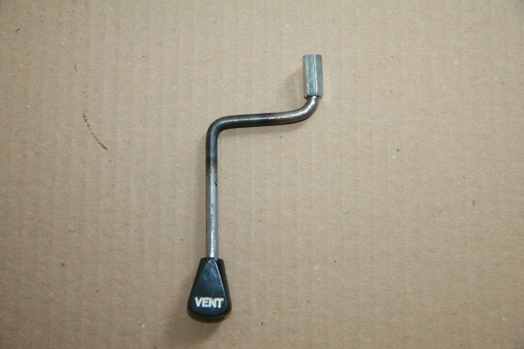
New Scuttle Ventilator Lever Extension
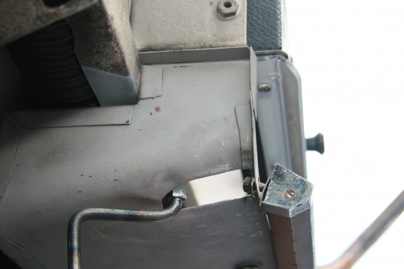
Newspaper Tray Slot for New Scuttle Ventilator Lever Extension
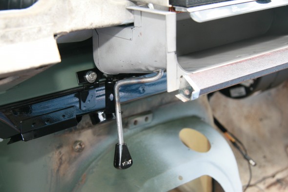
Newspaper Tray Slot for New Scuttle Ventilator Lever Extension
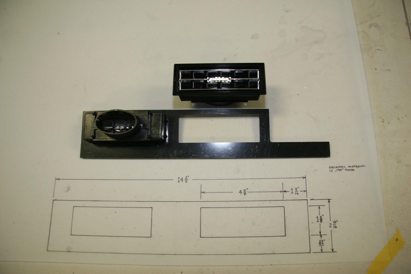
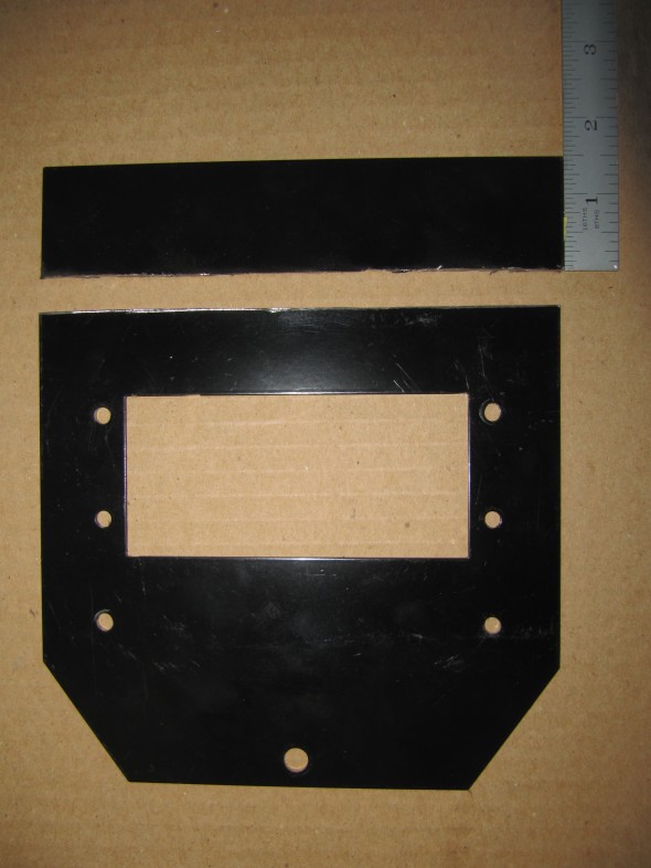
This allowed operation of the scuttle ventilator lid from below the newspaper tray which in turn permitted the location of the vent louvers to the center of the tray. Fortunately, I was able to find a local plastics company that was able to make a new air vent housing panel with the vent openings in the center of the panel.
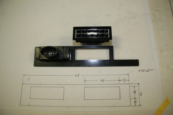
Drawing for New Air Conditioning Vent Panel
The new extension rod will either be chromed or painted black and will be shortened after I determine its optimal length and that will require the installation of the seats, and the steering wheel. I will also need to put an opening slot in the LH Scuttle Top Casing Assembly to permit movement of the lever.
The central instrument panel is covered in a material called Rexine. As Eric Kriss points out in his Blog, Rexine “was manufactured by Rexine Ltd of Hyde, England, is cloth impregnated with cellulose nitrate, camphor oil, pigment and alcohol, and then embossed to look somewhat like leather. Needless to say, it’s now unobtainium.

Rexine Ad
In 1960, Rexine was much cheaper than leather, but that probably wasn’t the reason Jaguar chose it for the dash panel. It’s very thin, takes a razor cut without fraying, and could be wrapped around the tight corners of the copper panel.
The oils and alcohol in Rexine evaporate over time, so the material is now extremely brittle and easily breaks off like a piece of thin plastic.”
I was able to order some vinyl material from Aldridge Trimming in the U.K. http://www.aldridge.co.uk that I used to recover the instrument panel and the plastic or sheet metal vent louvre panel, so that everything will appear as if installed originally.
MK2 Instrument Panel Assembly
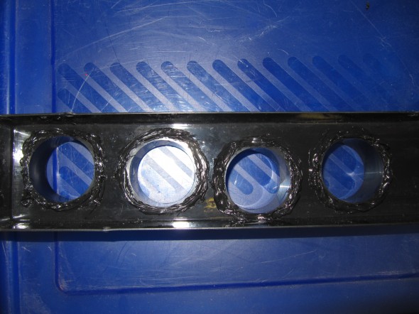
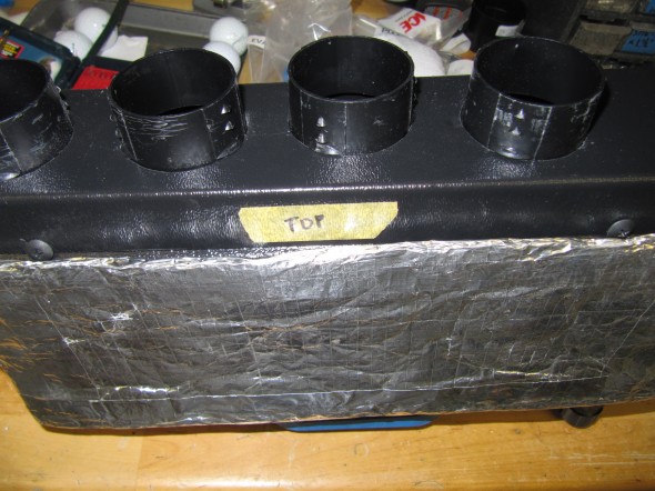
To run the vent hoses to the center louvers requires opening up the top and back of the newspaper tray. While I filed and sanded the edges to be smooth, the instruction call for applying black duct tape to avoid sharp edges. I will have the newspaper tray powder coated. The images below show the modifications including the lever slot. Once the LH and RH wood fascia are mounted to the car, the product will have a nice integrated and finished appearance.
Modified Newspaper Tray for Air Hoses
Modified Newspaper Tray for Air Hoses

Central Vent Louver Hoses
A Much Better Look In My Opinion
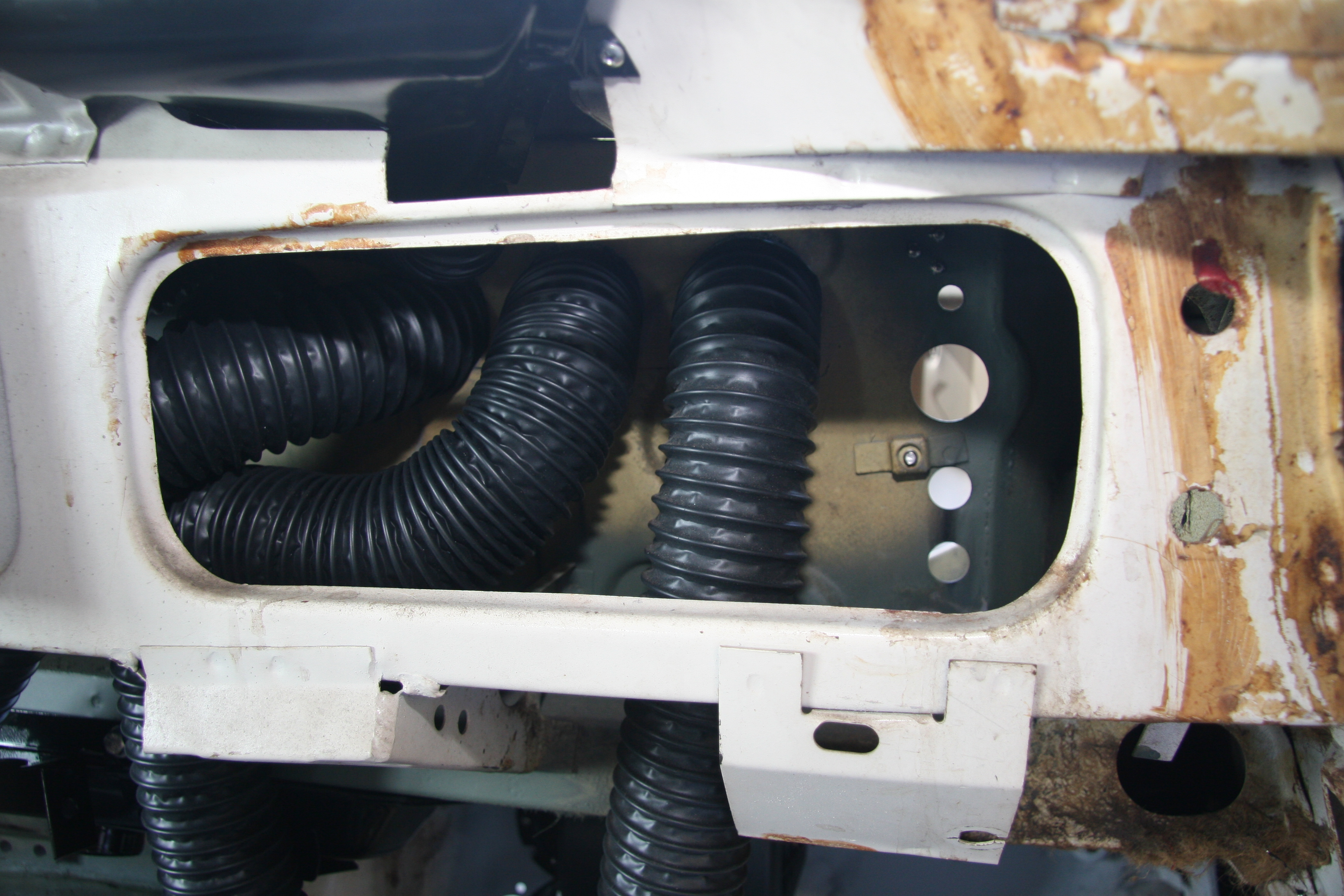
For the final trial fitting, I removed the evaporator from the firewall and connected all four hoses to the plastic evaporator outlets and then carefully pressed/pushed the evaporator with hoses through the four round openings and up tight against the firewall. The hoses behind the dash are quite a lot of spaghetti, but everything fits and the glove box cubby still mounts properly. Both demister nozzles with hoses are also connected to ensure fit.

Hose Installation Behind Cubby Glove Box
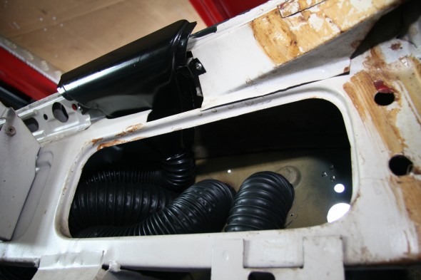
Hose Installation Behind Cubby Glove Box
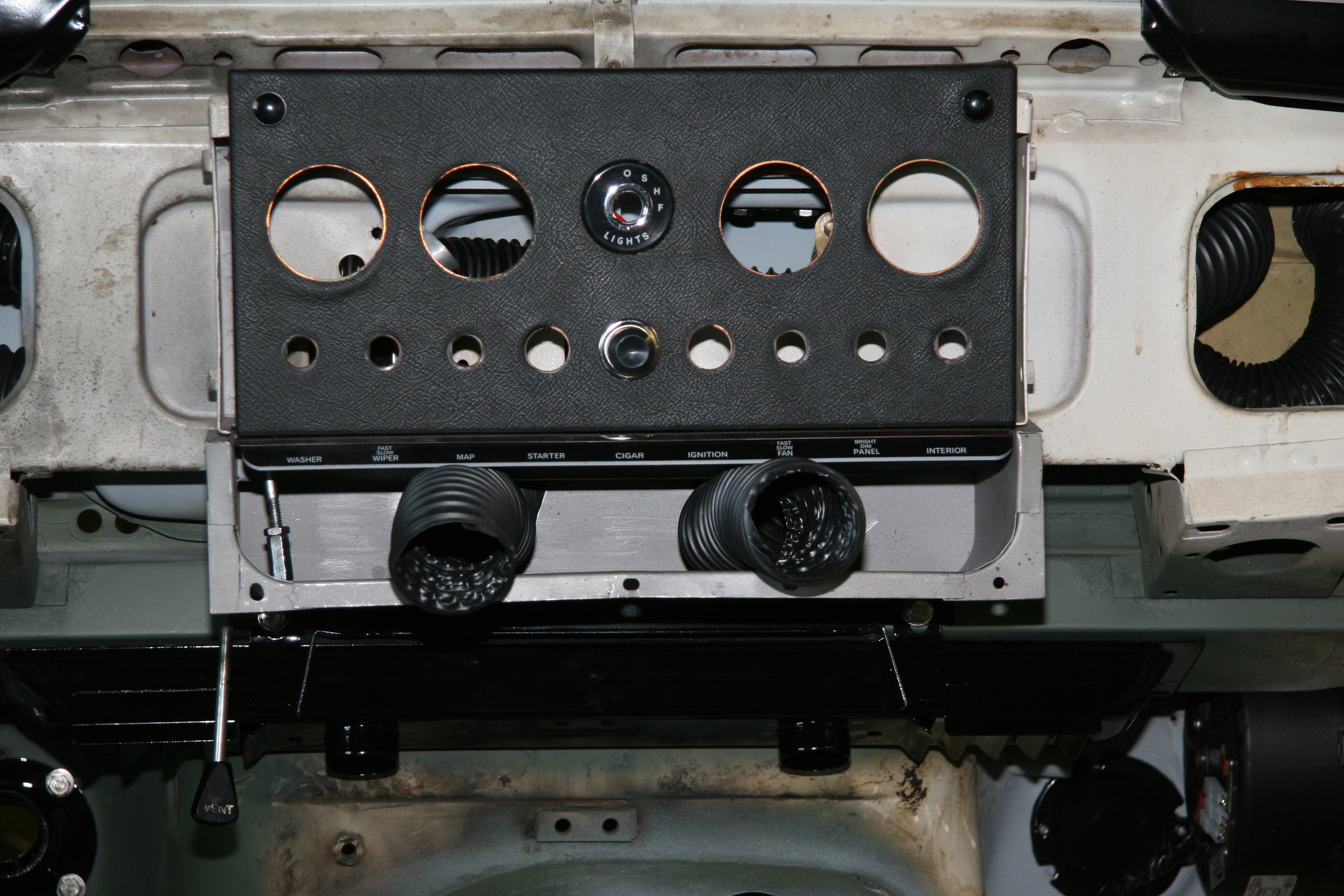
In the image below, I have the A/C vent hoses connected, so this is what my final installation will look like:
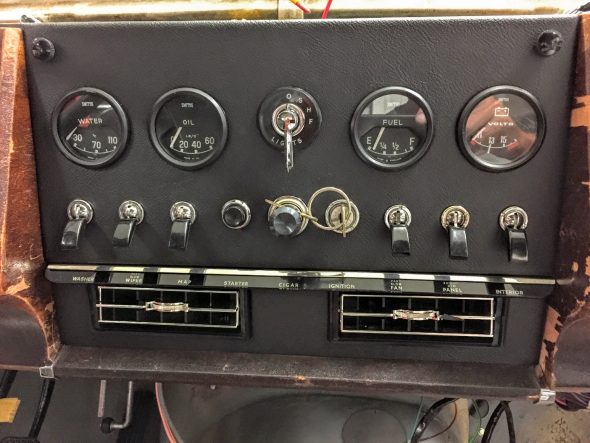
Center Air Conditioning Vents and Face Plate
Of course, it is just my opinion, but I think my modifications have yielded a much better esthetic appearance than the RetroAir kit. However, it also involved considerably more work. Once the wood is refinished, I think the central panel will look “factory!”
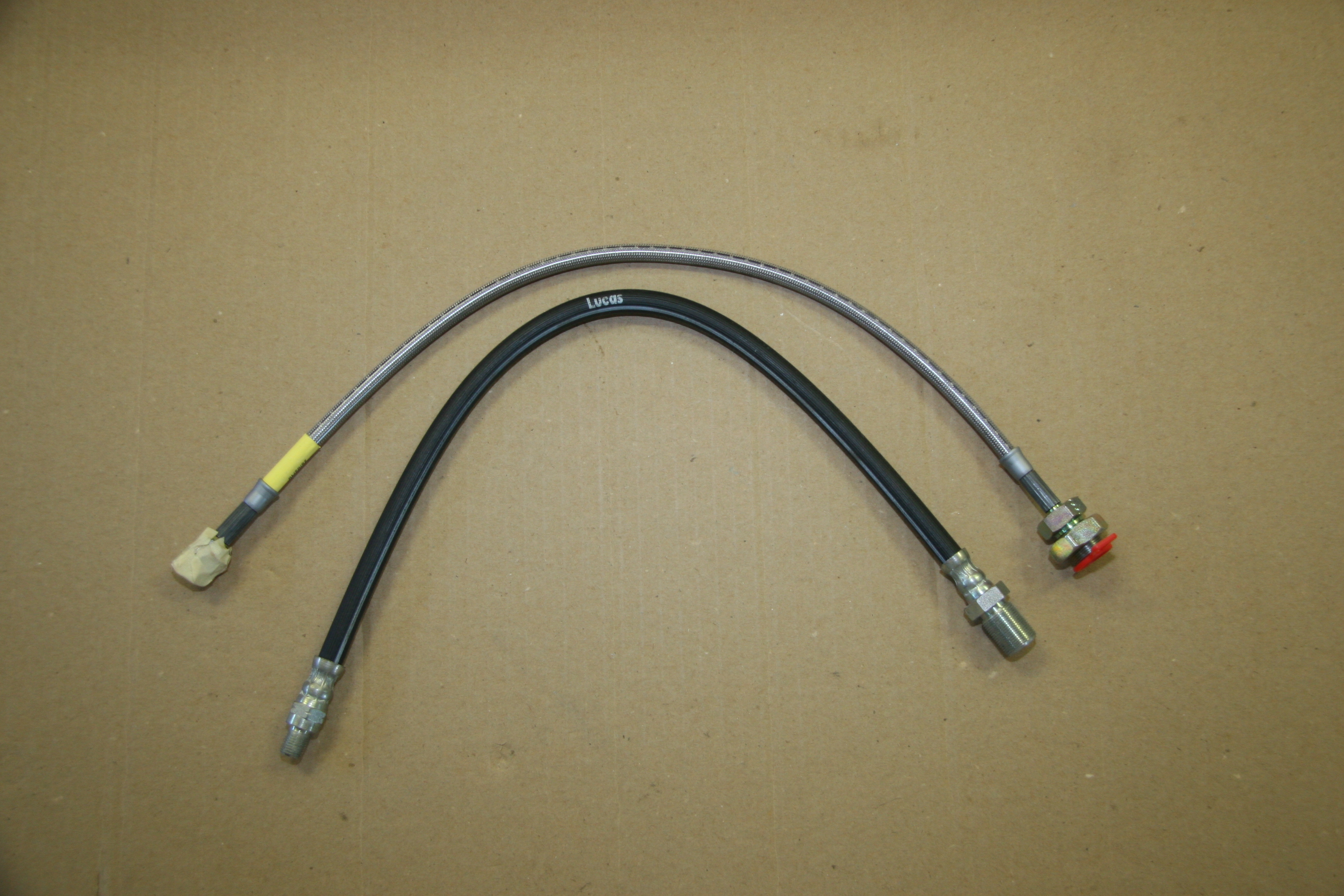
Air Conditioning Hoses
Four air conditioning hoses are supplied with the kit. The shortest #6 5/16″ hose, in my case 31 1/2″ long, is used to connect the drier and the condenser.
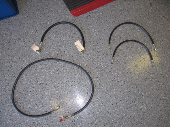
Air Conditioning Hoses
I reinstalled the grommets next to the condenser first. Then, BEFORE THE CONDENSER WAS MOUNTED, I CONNECTED THE HOSE FITTINGS. I also used a very small amount of anti-sieze on the threads. The threads on the condenser are soft and can easily cross-thread if not careful. Tighten with a 3/4″ wrench. This hose I used as supplied. I believe I ended up modifying the lengths of all of the other hoses to suit my particular needs. With the hoses attached to the condenser, and after making sure they were not chafing in the rubber grommets, I attached the condenser to the brackets mounted on the car on either side of the radiator grill opening.
The next step was to determine the routing of the hoses along the outside of the RH Front Wing Valance and to mount the drier.
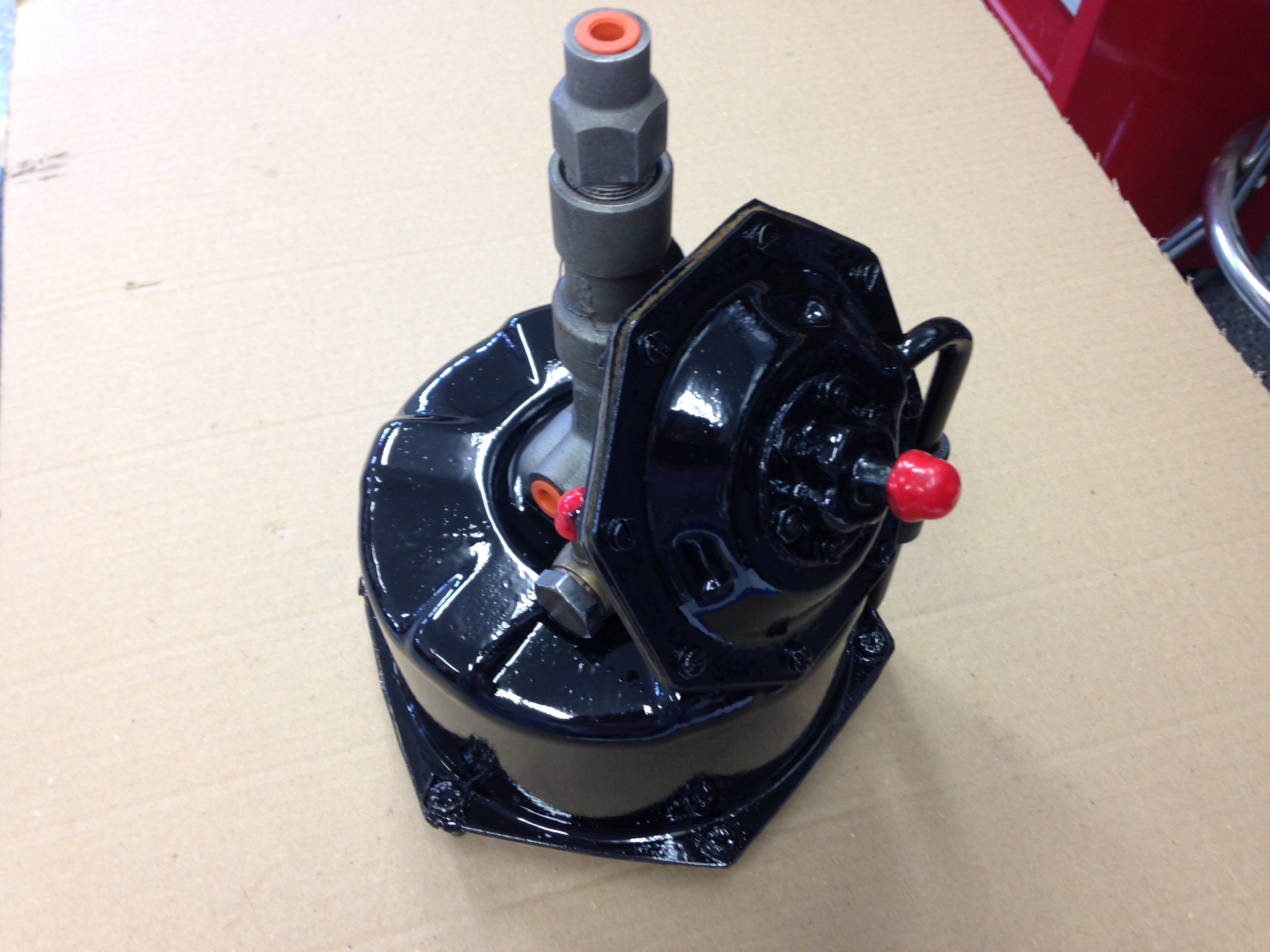
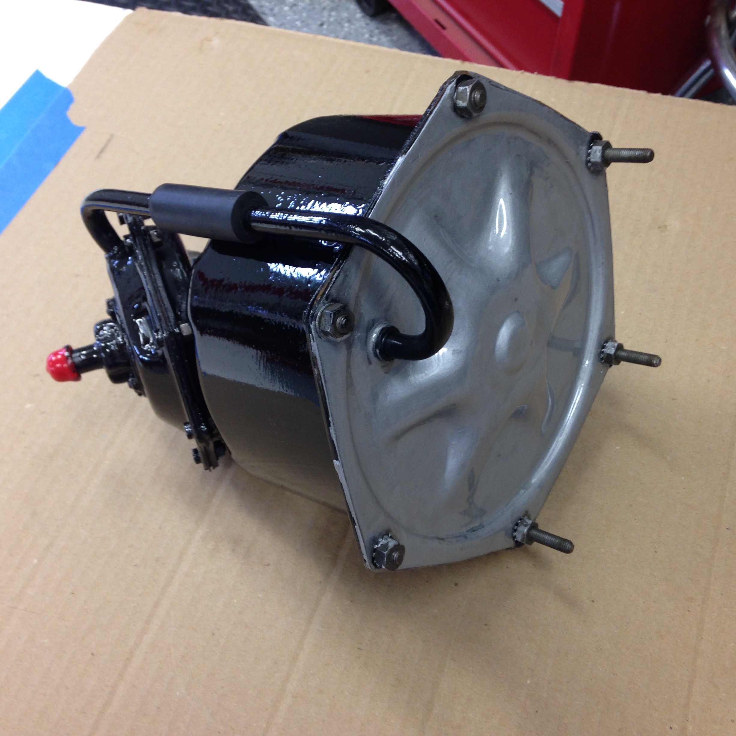
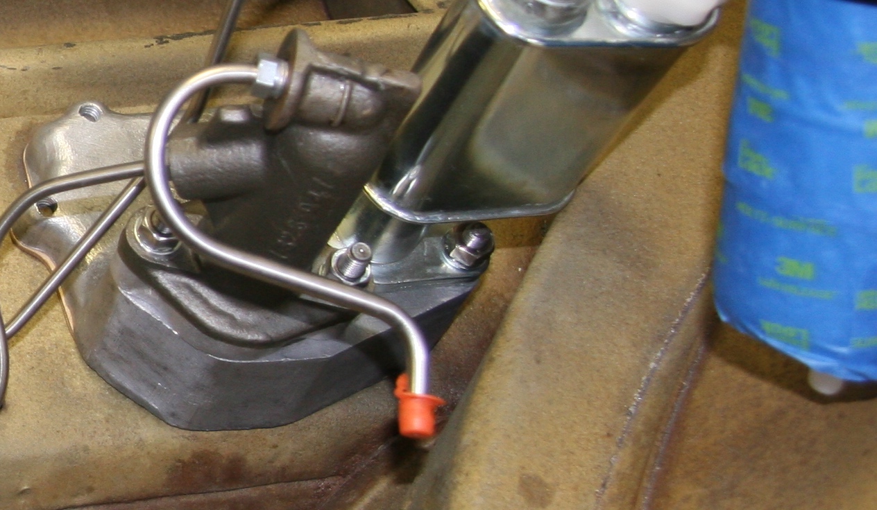
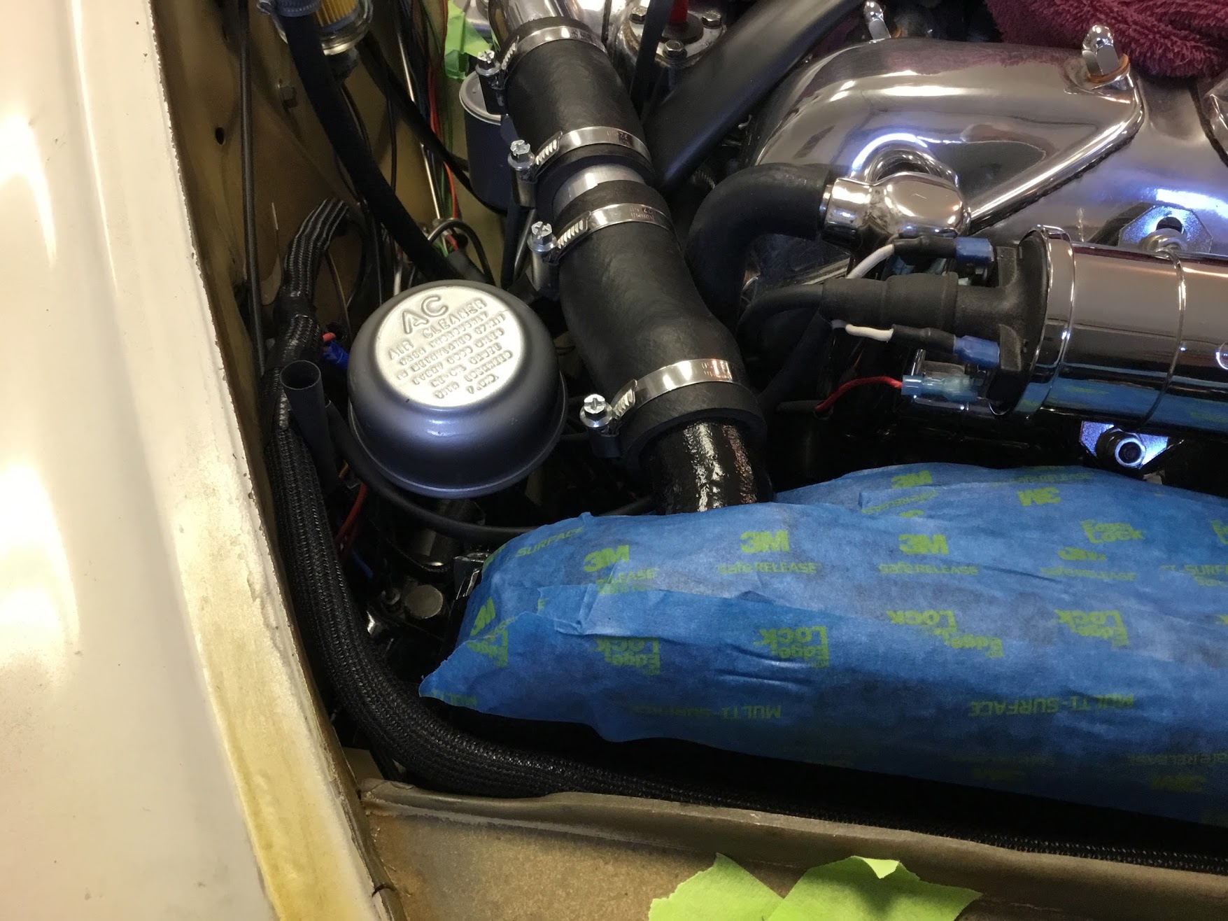
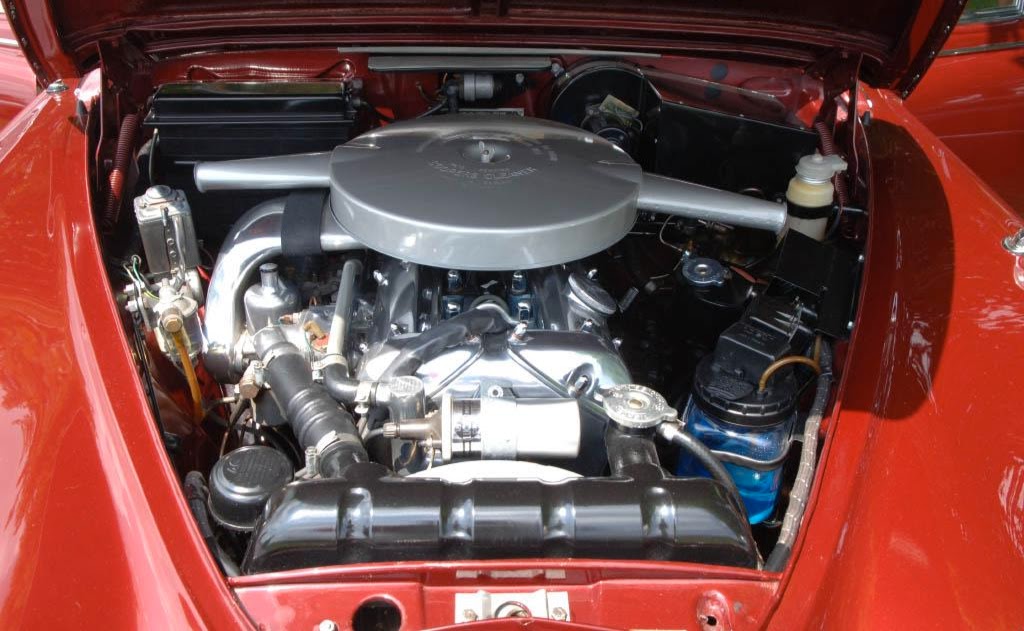
Brake Booster Cowl and Vacuum Tank Mounted
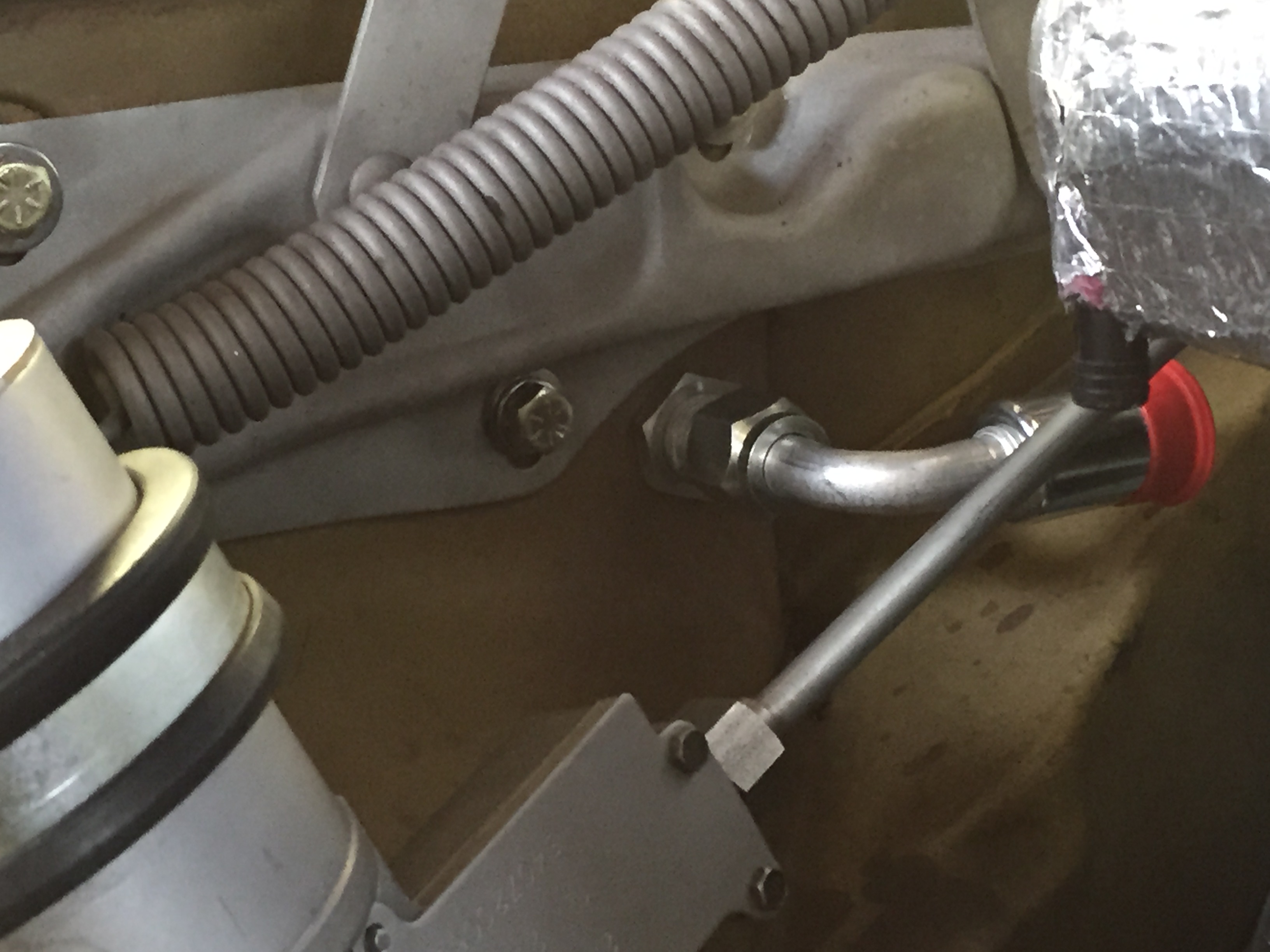
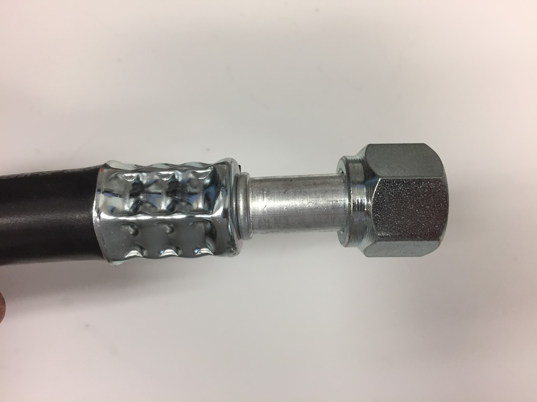
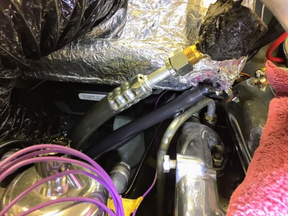
The longest #8 13/32″ discharge hose, in my case 93″ long, is used to connect the compressor and the condenser. The 45 degree angle end of the hose attaches to the condenser. The RetroAir instructions call for routing this hose along the outside of and then through the RH engine bay valance. It is suggested that a hole be drilled in the valance suitable for a supplied rubber grommet to then allow the hose to pass through.
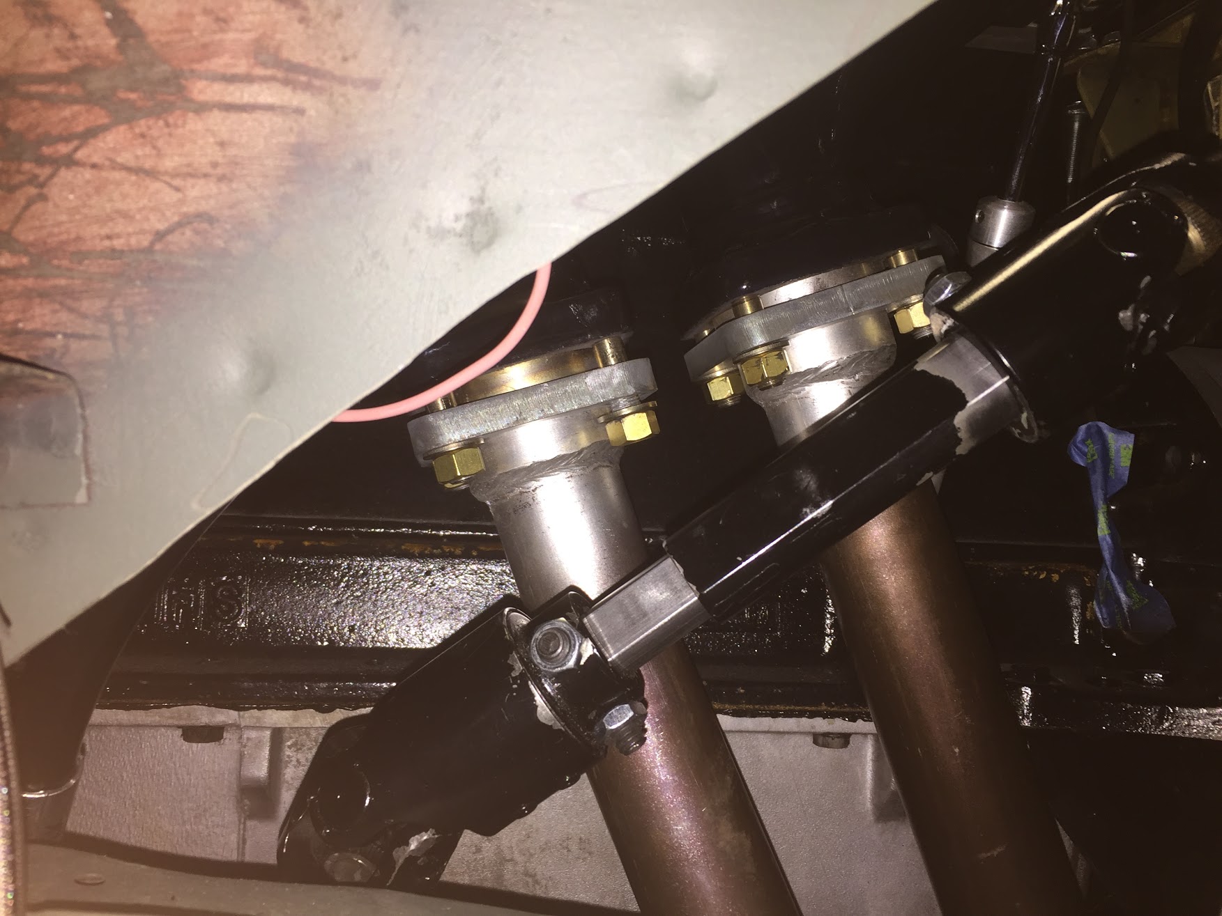
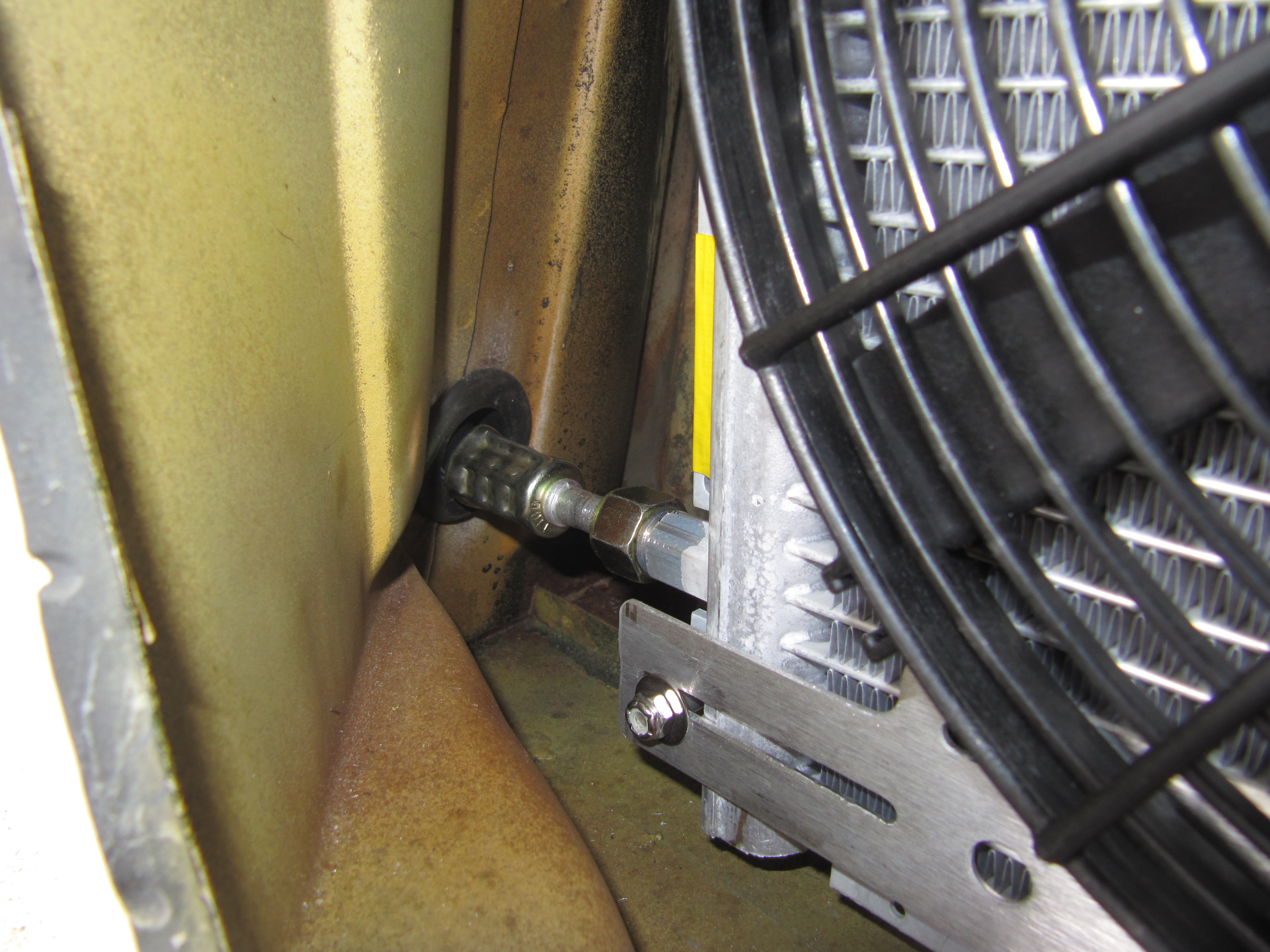
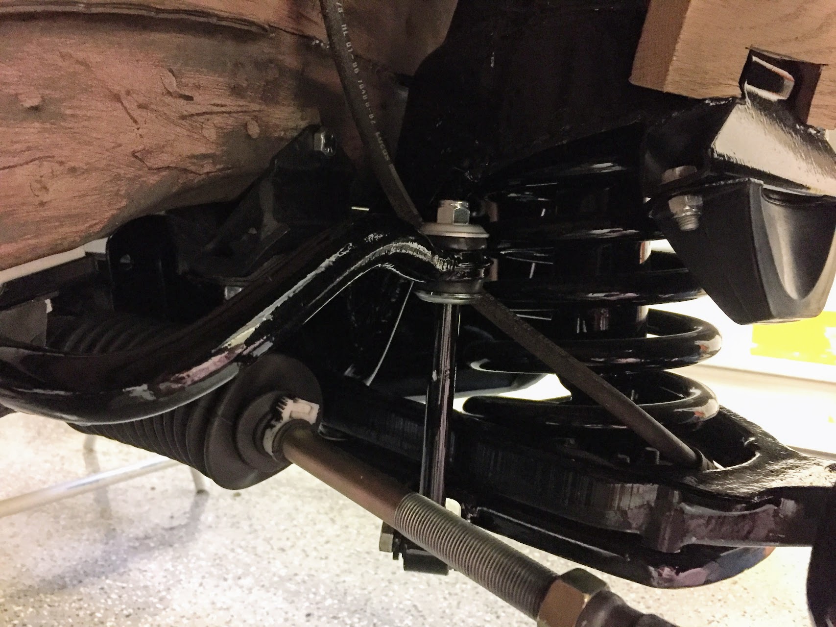
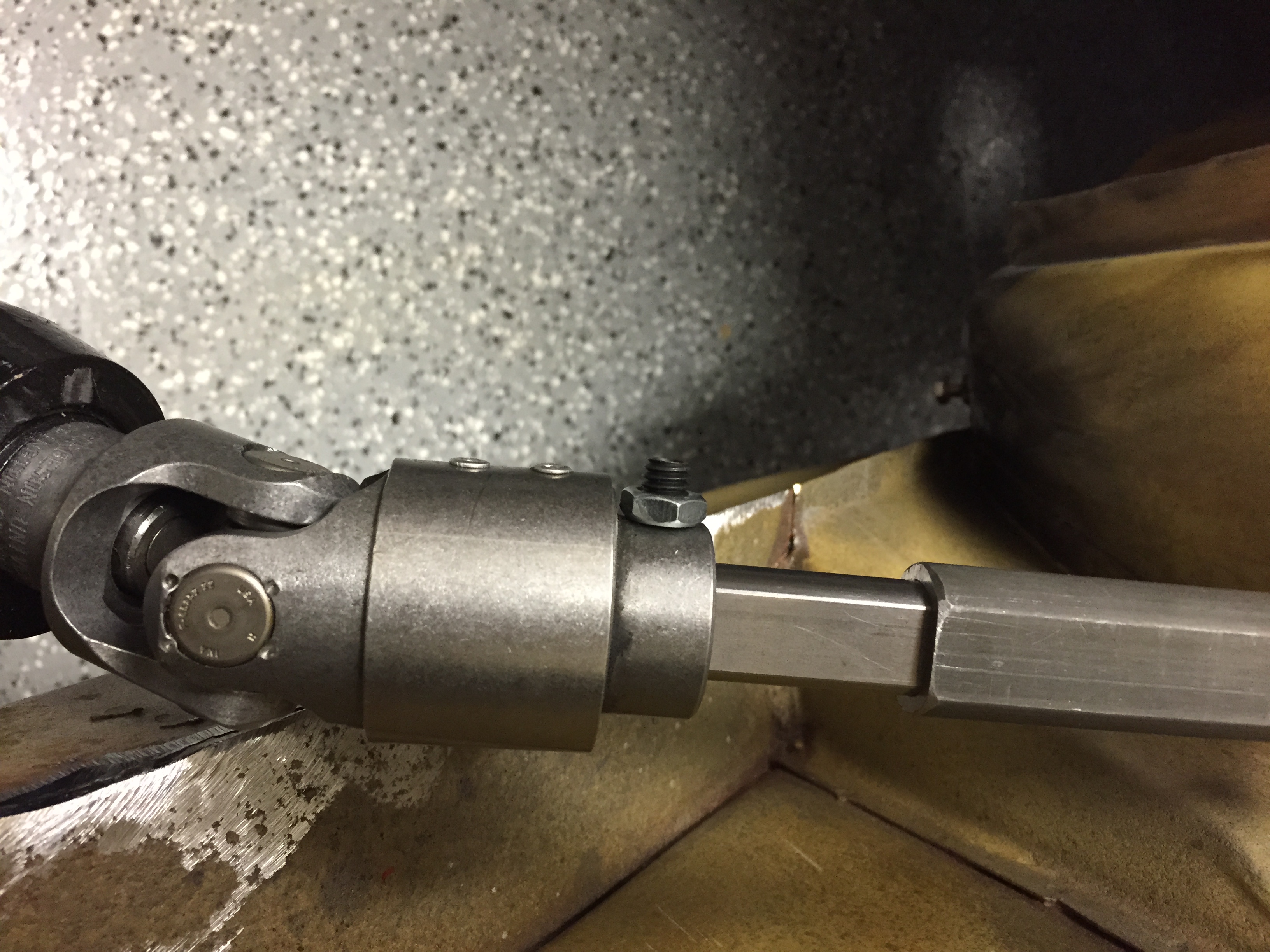
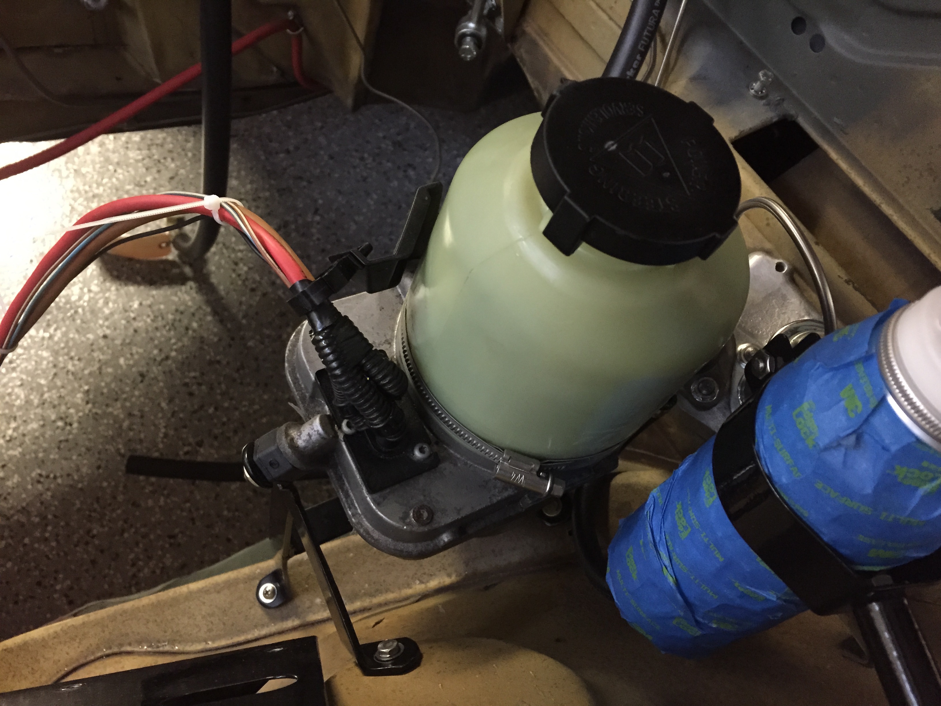
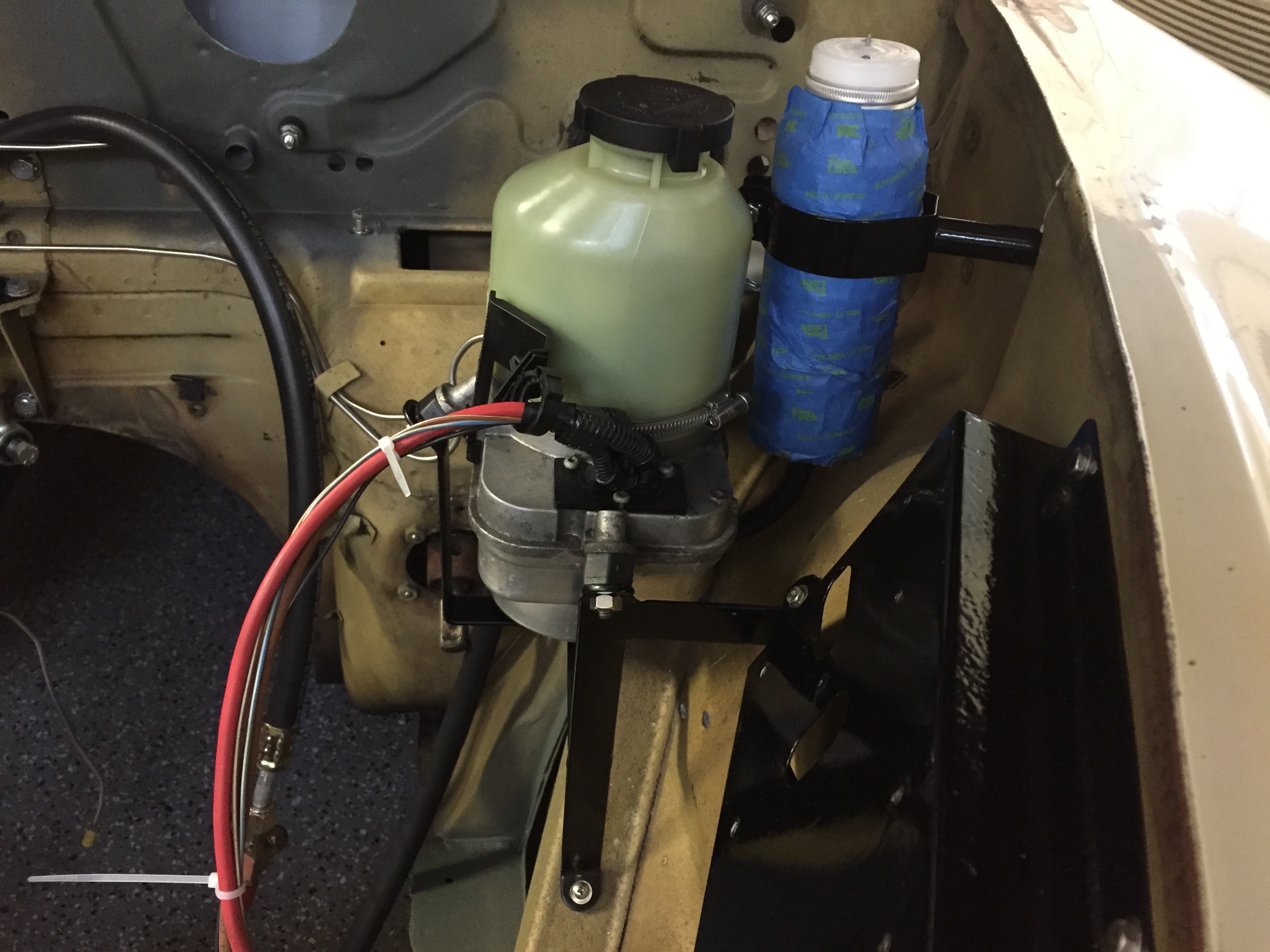
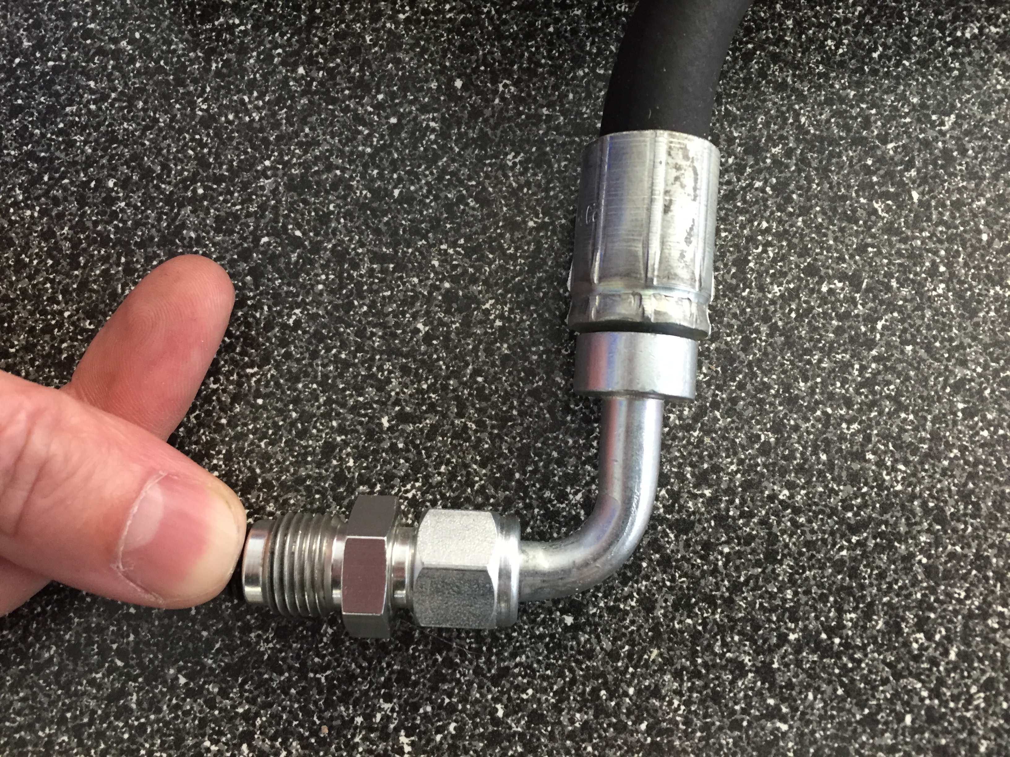
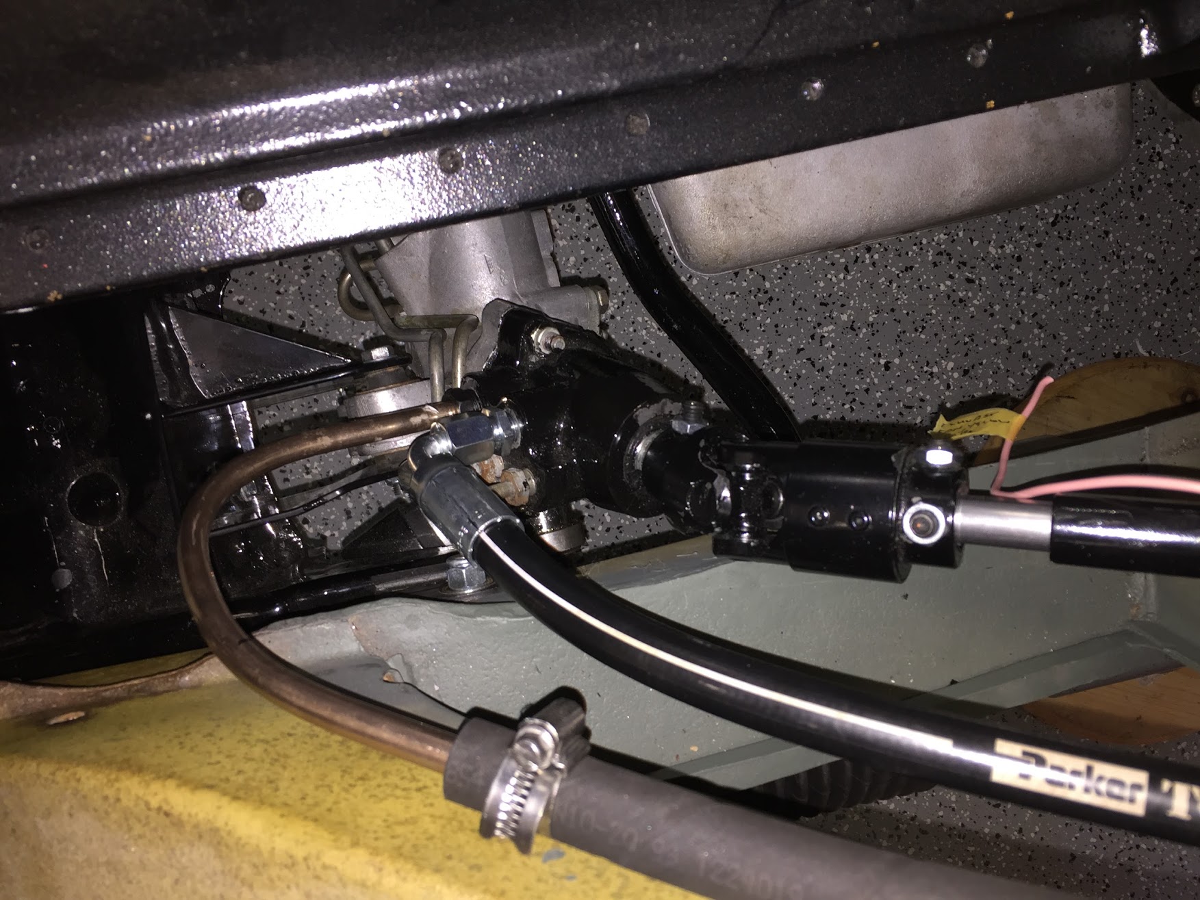
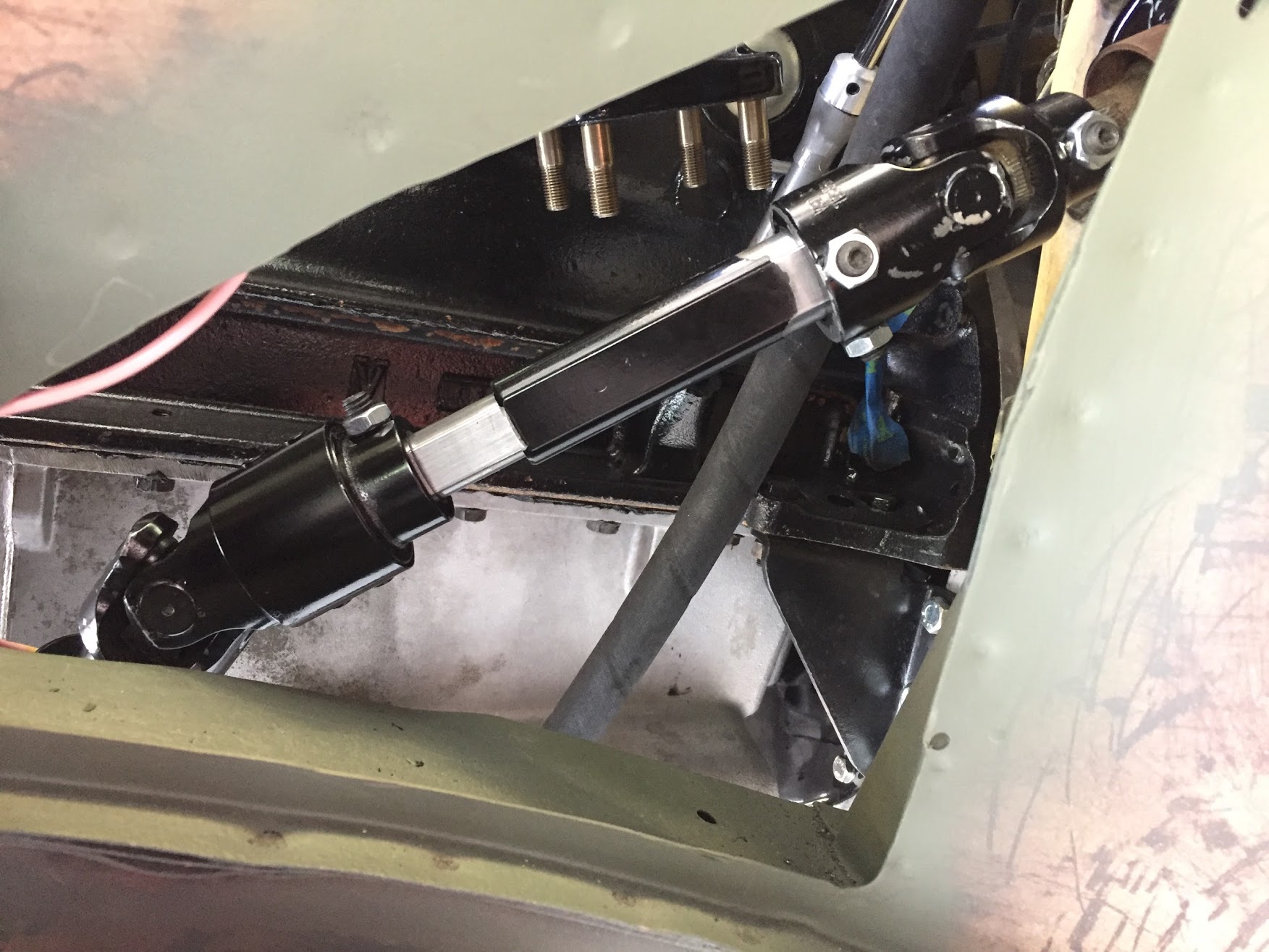
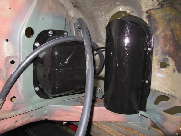
In another departure from the RetroAir instructions I chose to cut the hose and install a hard 90 degree hose fitting in the valance. See images below. The hole for the fitting is high on the valance near the bonnet hinge. It is approximately 1 1/2″ behind the lower hinge mounting bolt and about 1/2″ below it. I used a stepped drill bit to drill a 3/4″ hole in the valance for the hose fitting. This image shows the mounting in the wheel well side of the valance.
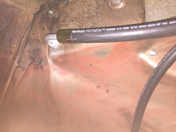
Discharge Hose LH Valance Fitting Location
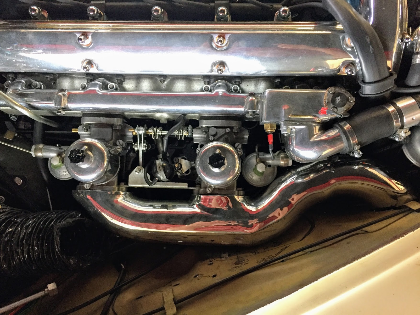
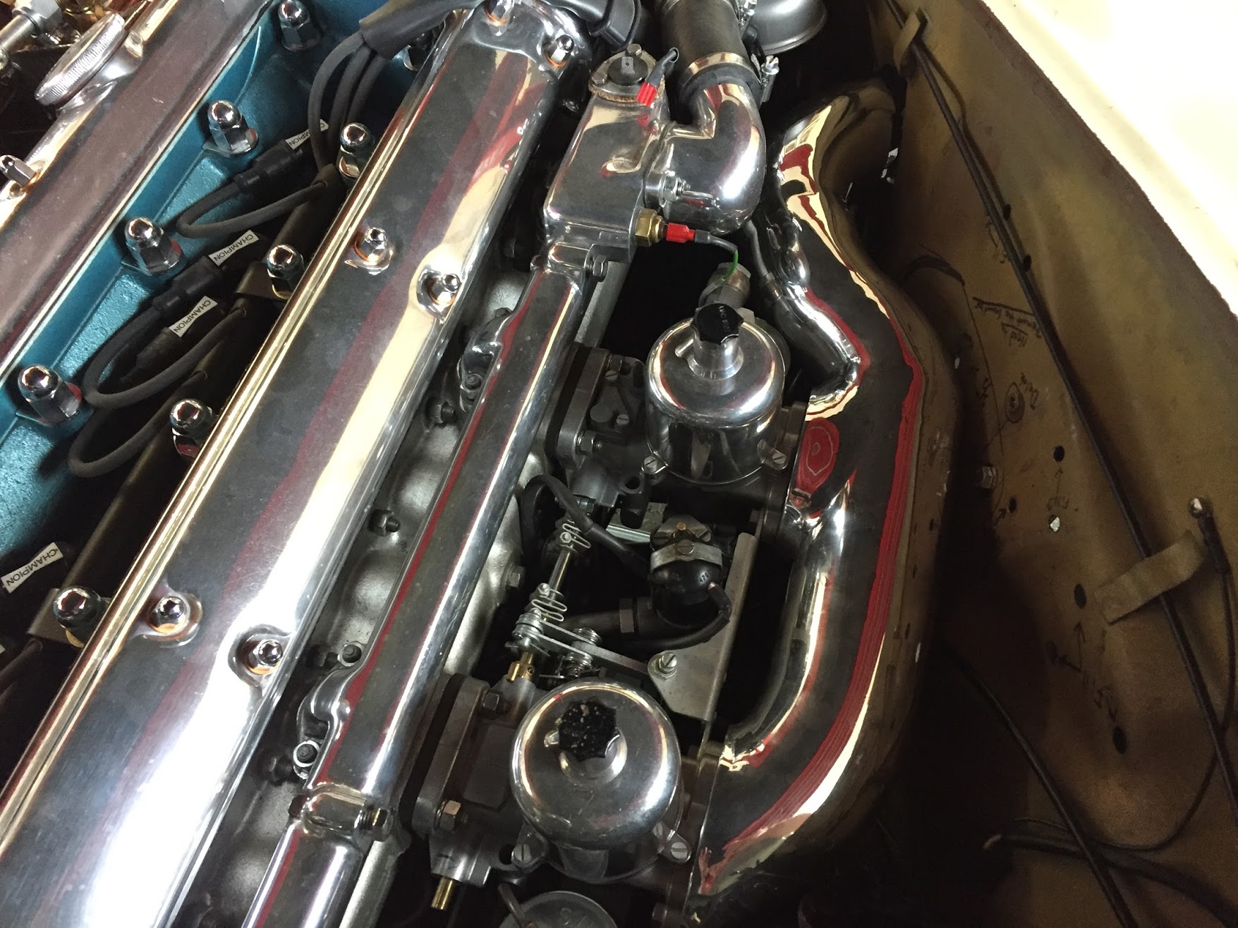
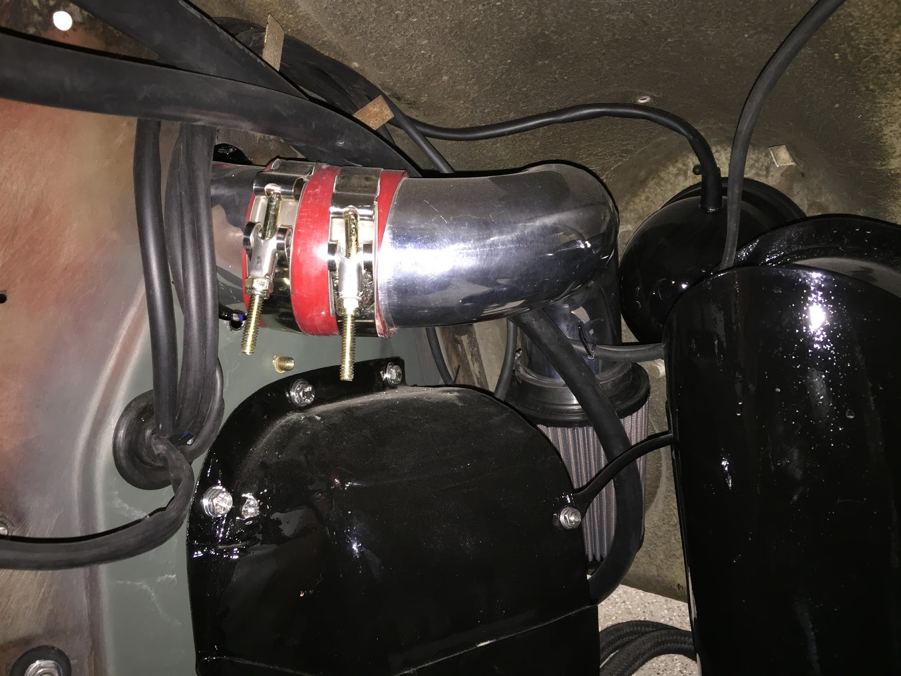
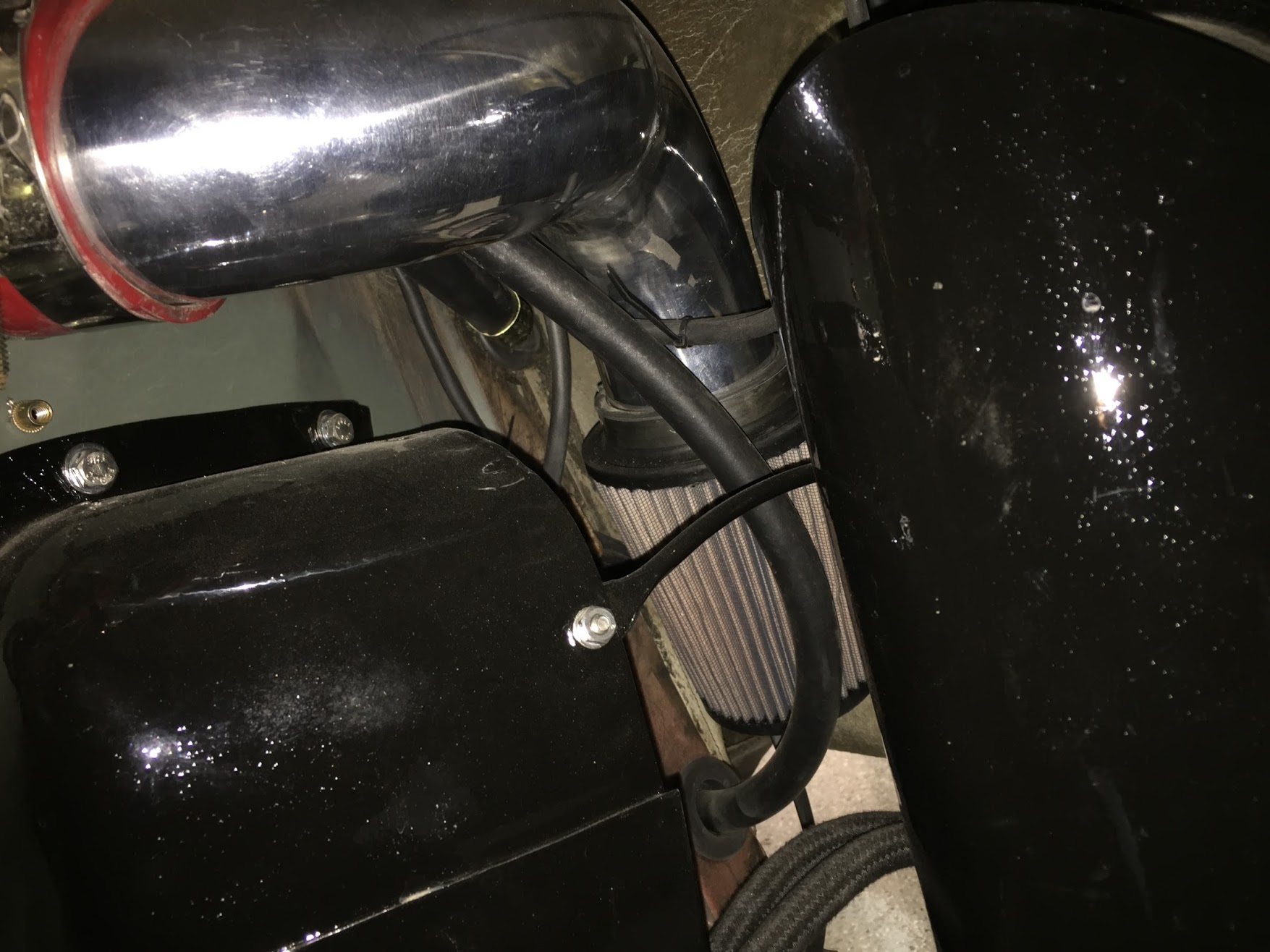
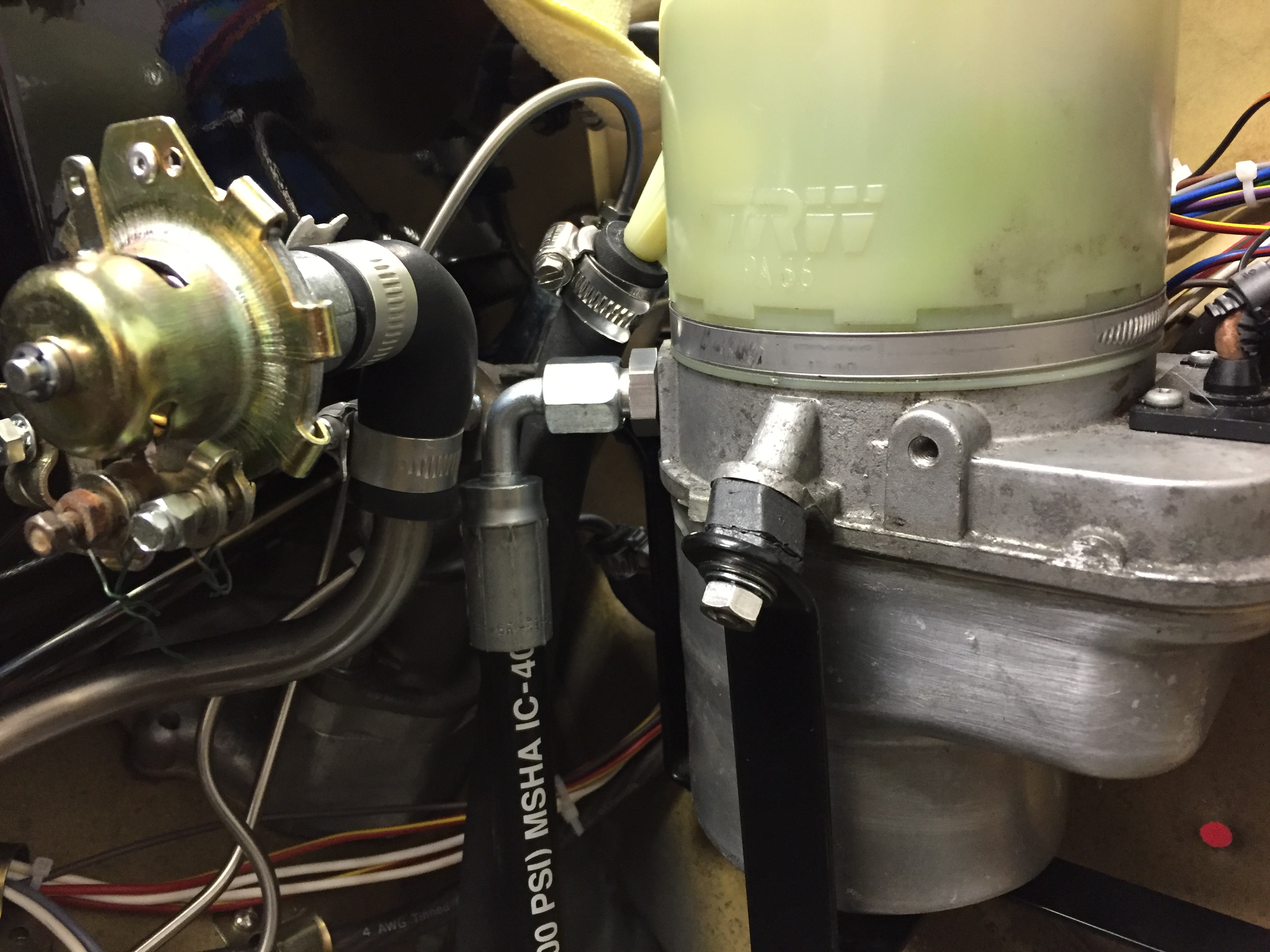
These two images show the ninety degree elbow fitting used on the engine bay side of the valance. The hose will channel below the evaporator, rest against the firewall and wrap around to connect with the compressor. I am pleased with this approach as the hose ends up being much less obtrusive in the engine bay than it would have been using the RetroAir routing.

Discharge Hose LH Valance Fitting Location

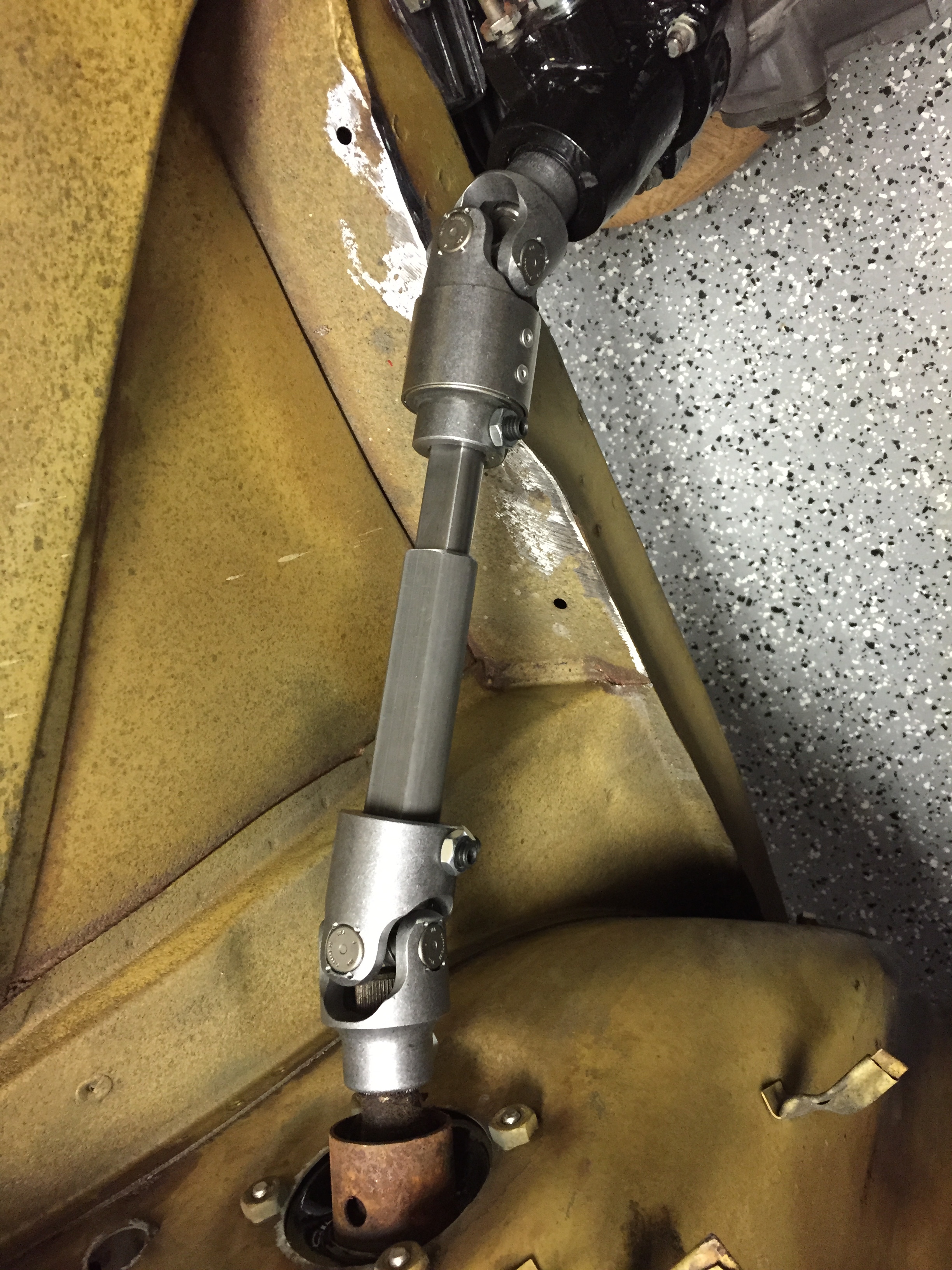
Discharge Hose Routing from Condenser to Compressor
The end of the hose with the ninety degree fitting attaches to the compressor. Again, anti-sieze on the threads and tighten the hose fitting while the condensoer is still loose to avoid binding. Tighten with a 7/8″ wrench.
Hose Fittings and Crimping
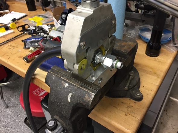
Crimping the fittings on the air conditioning hose is really quite easy IF YOU HAVE THE PROPER TOOL! In my case I borrowed a Mastercool crimper from a friend’s shop. The tool can be mounted on a work bench but I just used a vice to hold it in place.
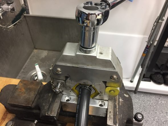
Hose Crimper Tool in Action
The tool uses various size dies that are color coded to match up with whatever size hose fitting you are using. The device is hinged to open, snap the two-piece dies in place and then close around the fitting. The pin on the left side in the image above is then inserted to lock the tool. One then simply turn the tightening shaft with a air gun or big wrench until the jaws of the tool fully close. Using a torque wrench to do the job, I found that approximately 80 lbs of force got the job done.
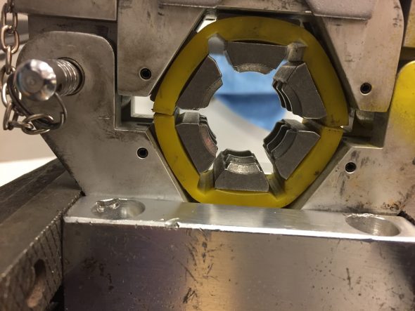
Hose Crimper Tool Sized Fitting
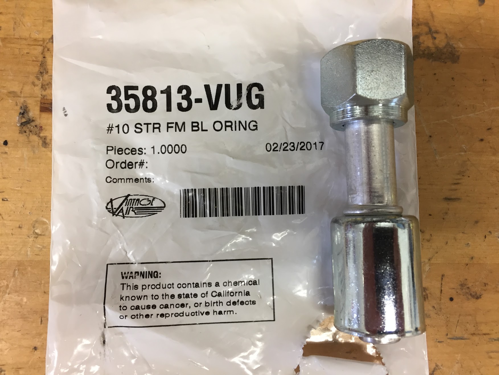
This happens to be a #10 size hose fitting before crimping.
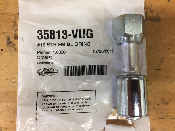
Hose Fitting Before Crimping
The image below shows the fitting in position ready to crimp. You should have about a 1/4″ of the fitting showing on either side of the crimping dies.
Hose Fitting in Position Before Crimping
As mentioned, I used a torque wrench to tighten the tool.
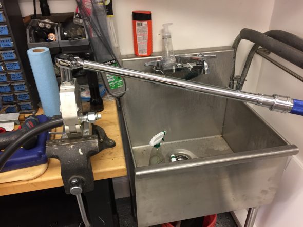
Crimping Tool Leverage
And here is an example of the finished product:
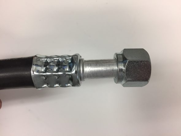
Hose Crimping Finished Product
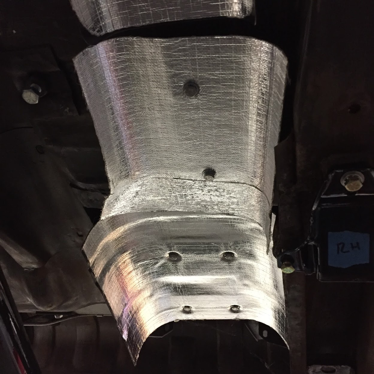
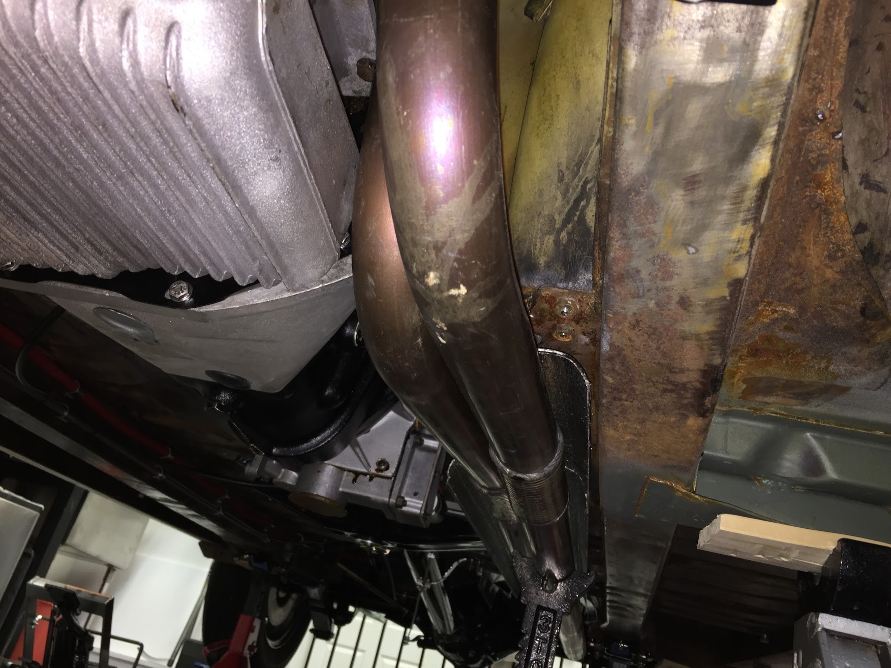
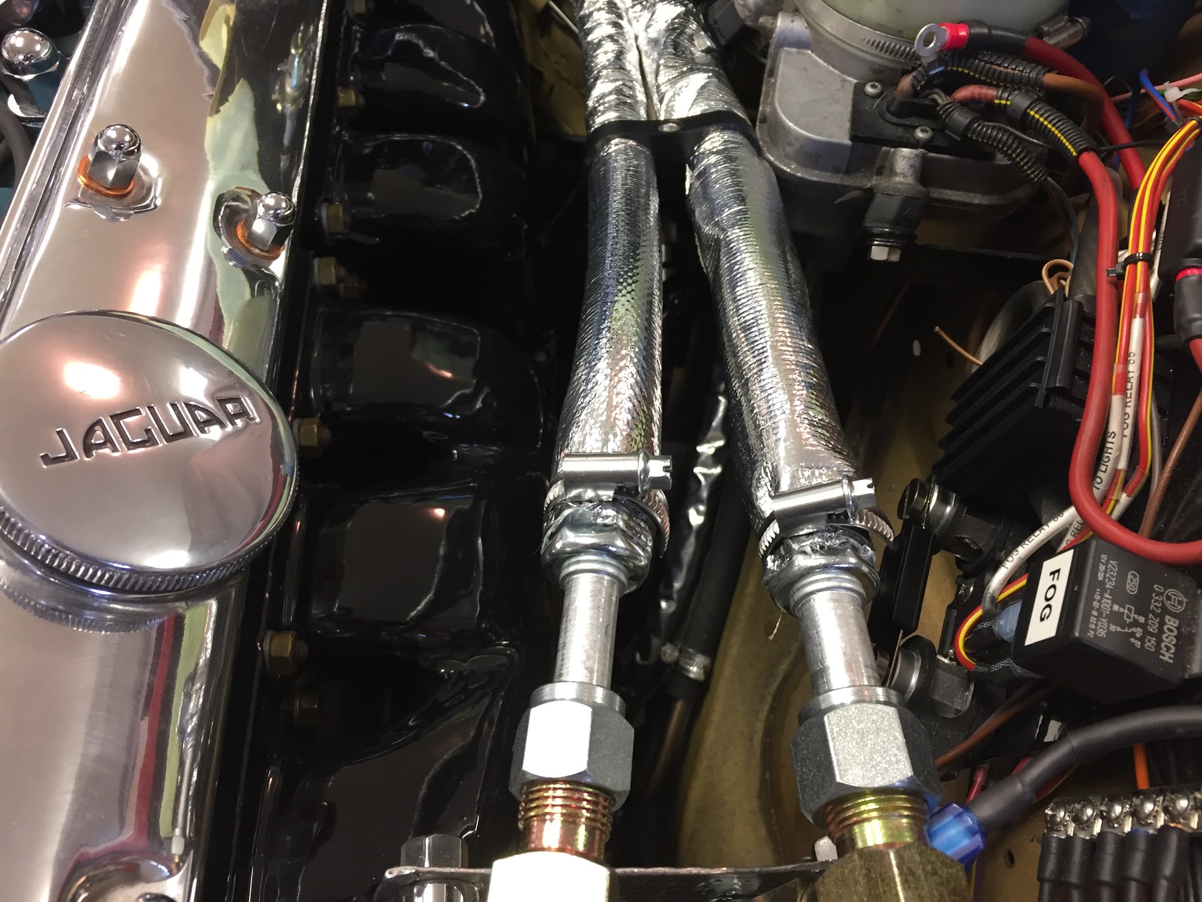
I used Thermotec’s Thermo Sleeve product http://www.thermotec.com/products/thermo-sleeve.html to help protect the hoses from the heat radiated from the exhaust manifolds that are unfortunately directly below the hoses mounted to the compressor. I used part number 14010 for the #8 hose and it fit perfectly. I used part number 14015 for the #10 hose. 14015 is a little large for the #10 hose, but it is the closest fit they have. The sleeves come in 3′ and 6′ lengths.
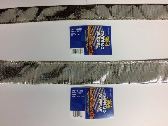
Thermo Sleeve
The image below shows the compressor hoses encased in the thermo sleeves. The ends are clamped to keep hot air out and to keep the appearance neat.
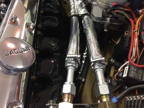
Thermo Sleeve on Air Conditioner Hoses
Drier
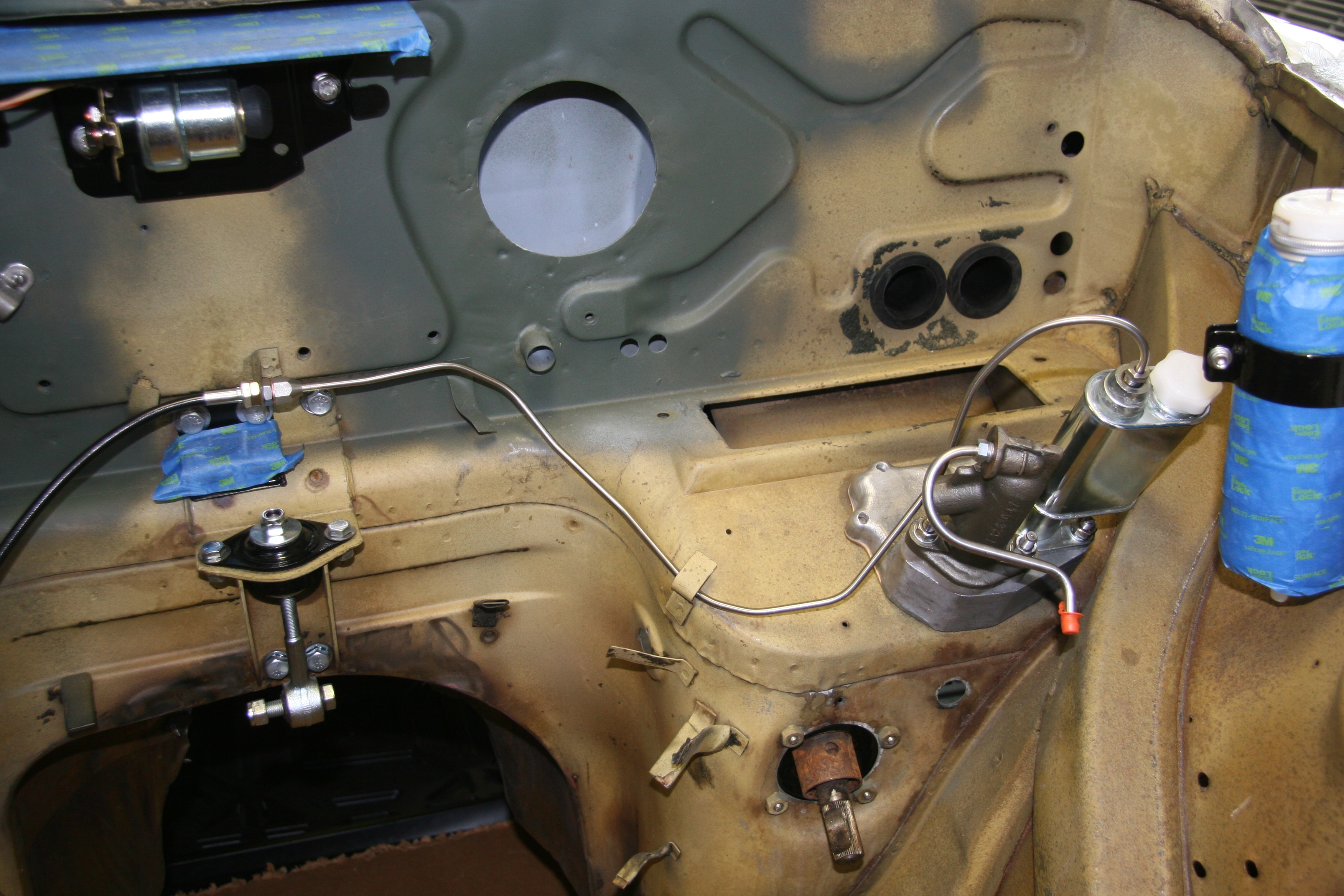
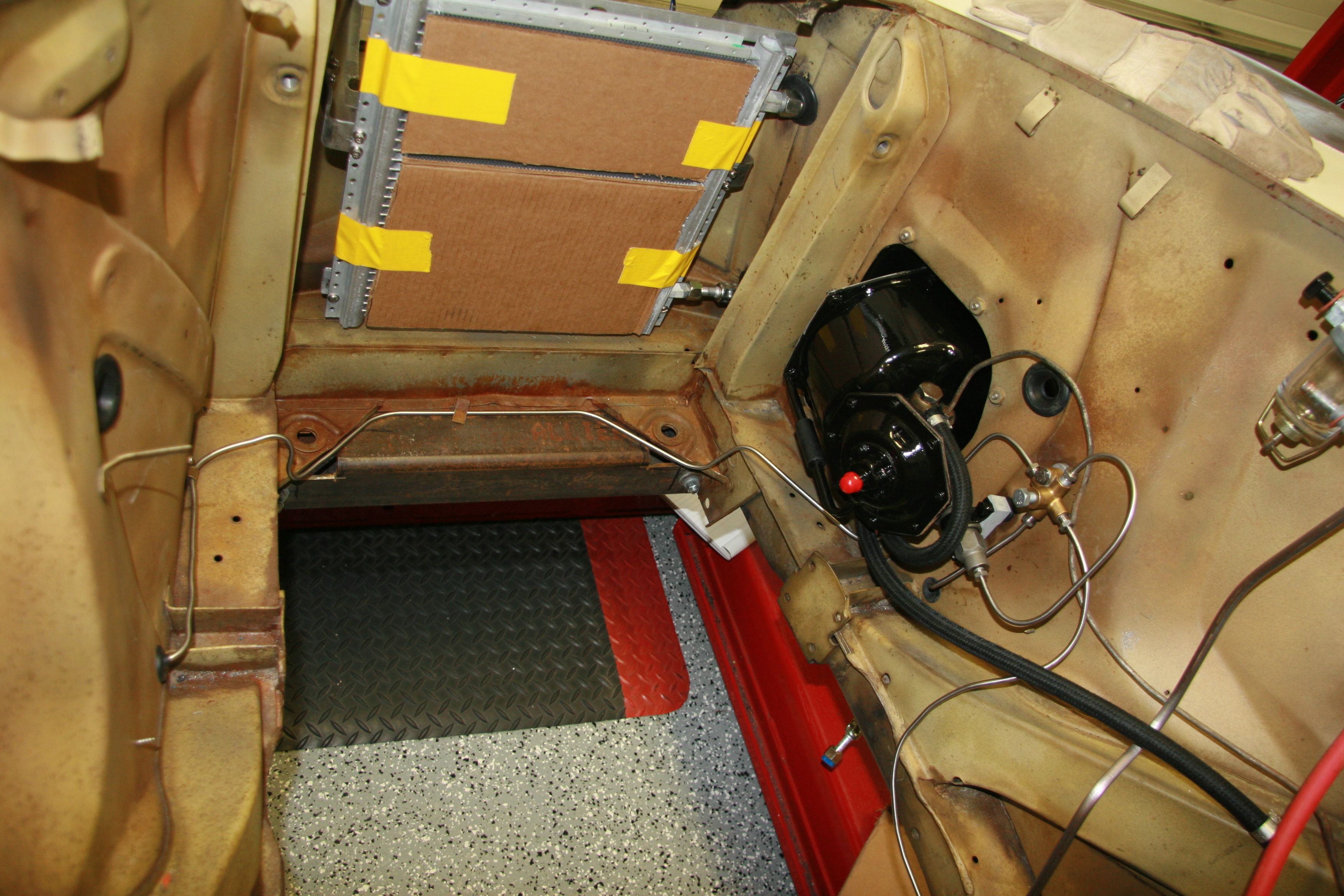
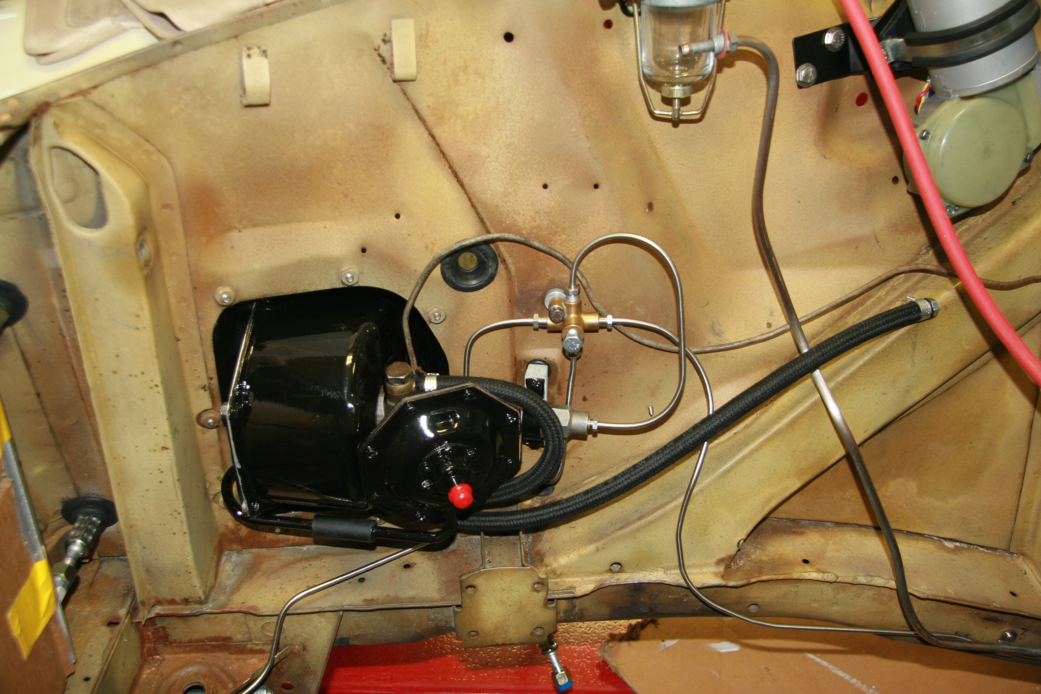
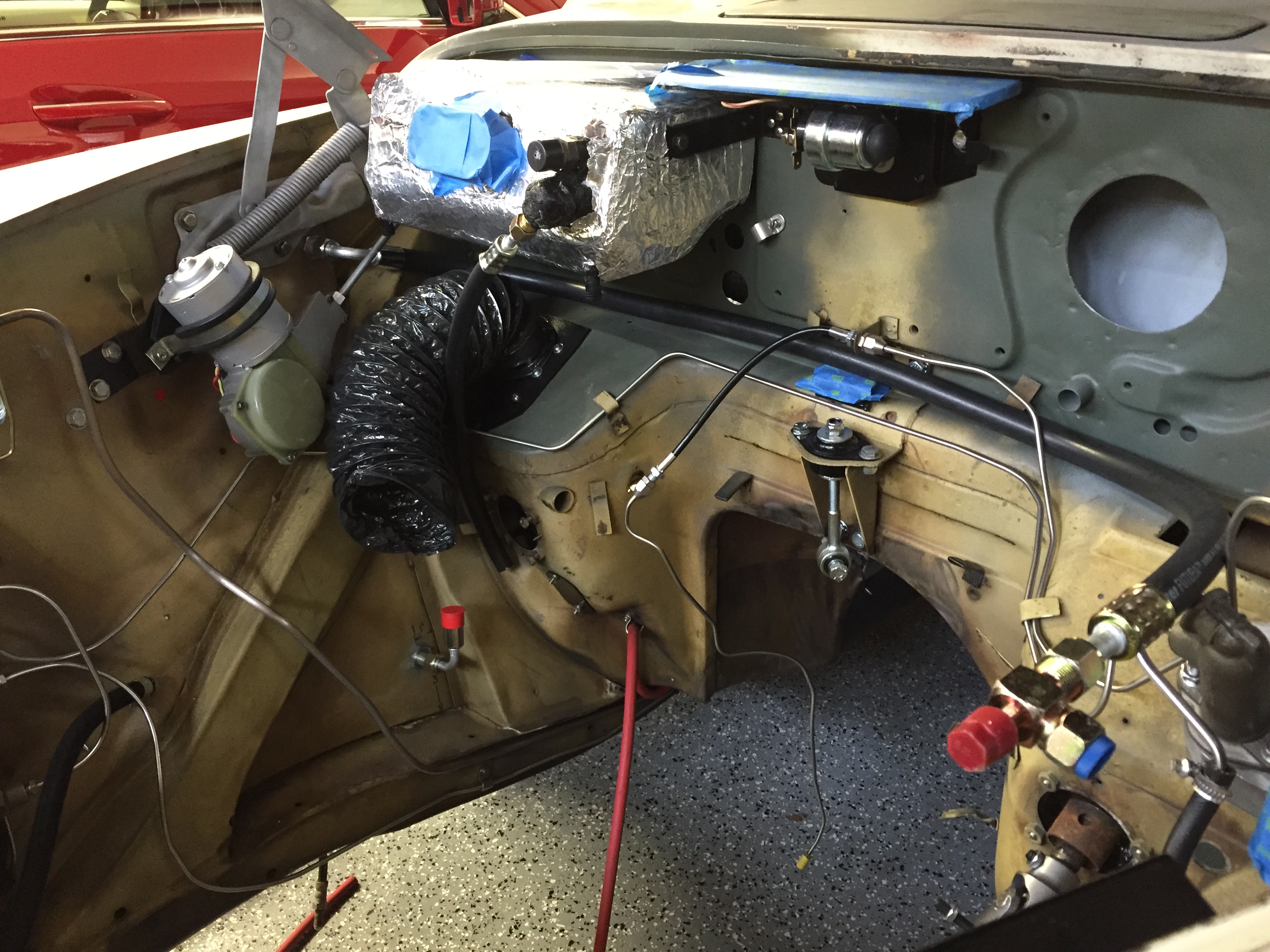
Whenever one adds modifications to a classic car mounting conflicts with other components must be considered. The RetroAir directions call for mounting the drier on the RH front wing valance assembly (wheel well wall). I planned to mount it at the suggested location, but I wanted to know what my hose runs would be before drilling any mounting holes.
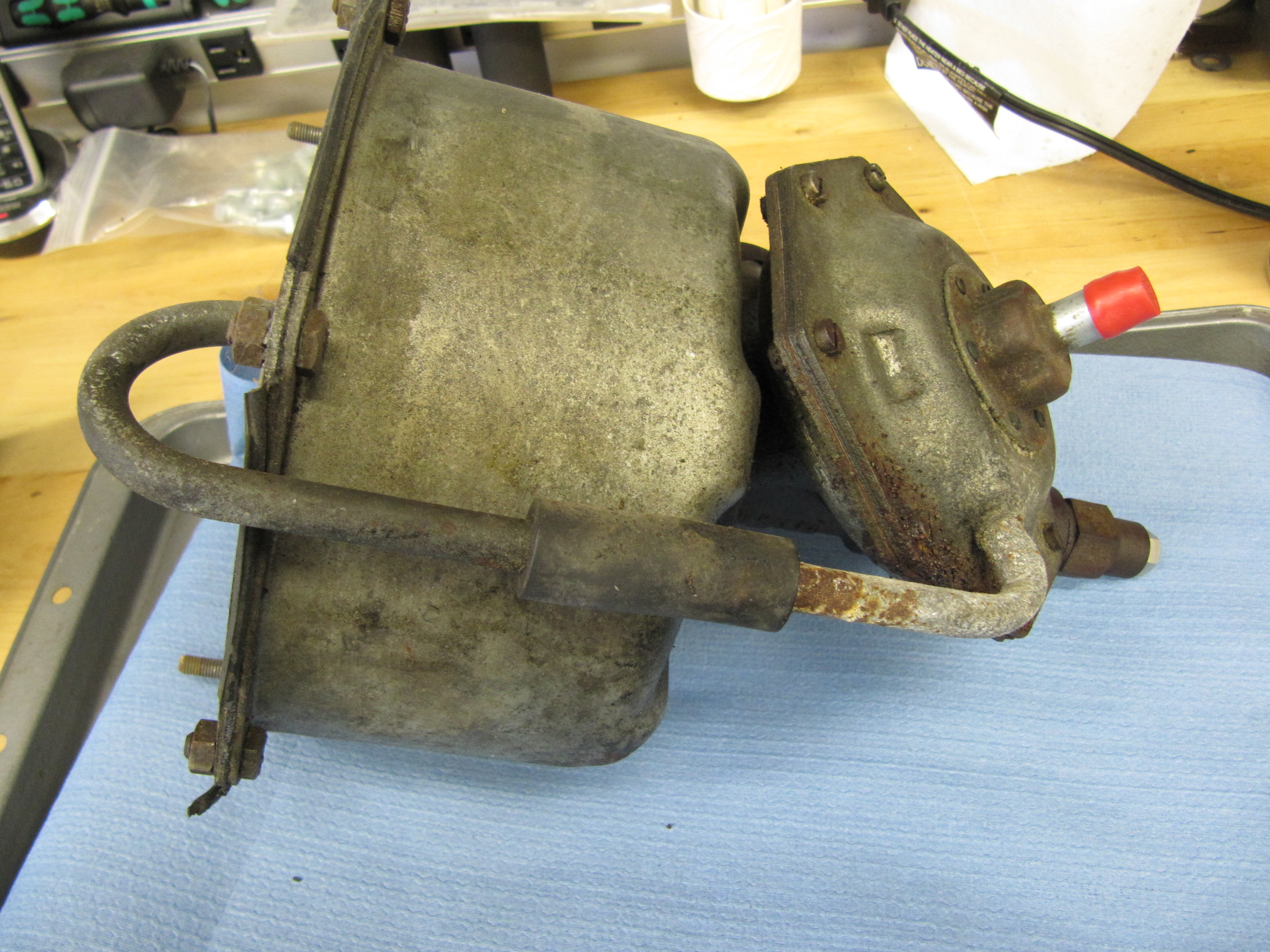
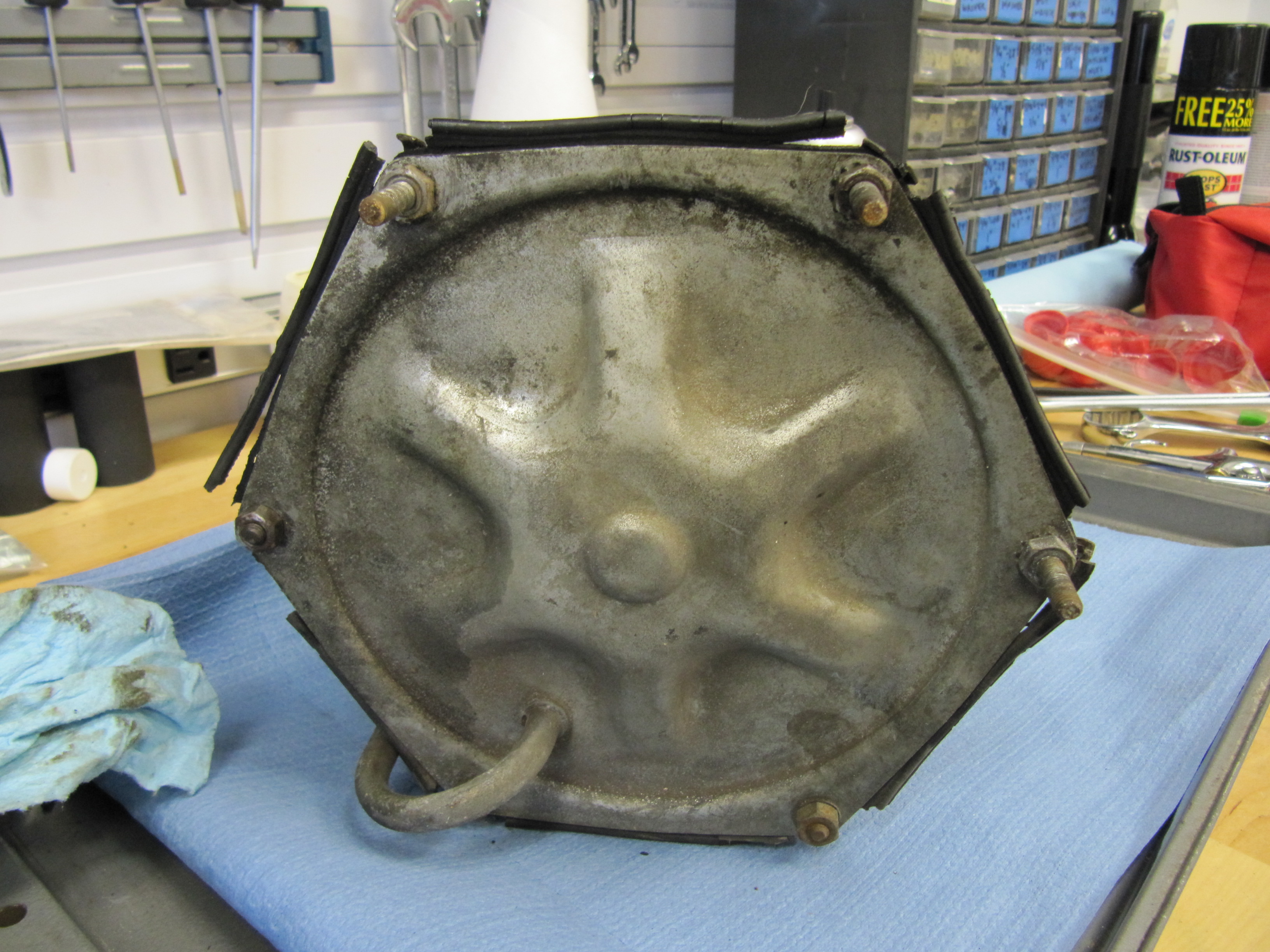
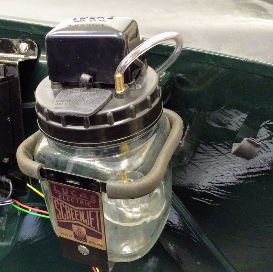
I went to considerable lengths to make sure I wouldn’t encounter mounting problems! I decided to go ahead and mount the brake servo cowl and the reservac vacuum tank to again ensure that I did not have any space conflicts with the hose routing. This required cleaning the mounting area and priming the metal. After drying, I mounted the cowl with eight stainless 1/4″-28 x 1/2″ hex head bolts with shake proof and flat washers.
Brake Booster Cowl Mounted
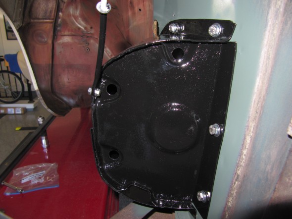
Brake Booster Cowl Mounted
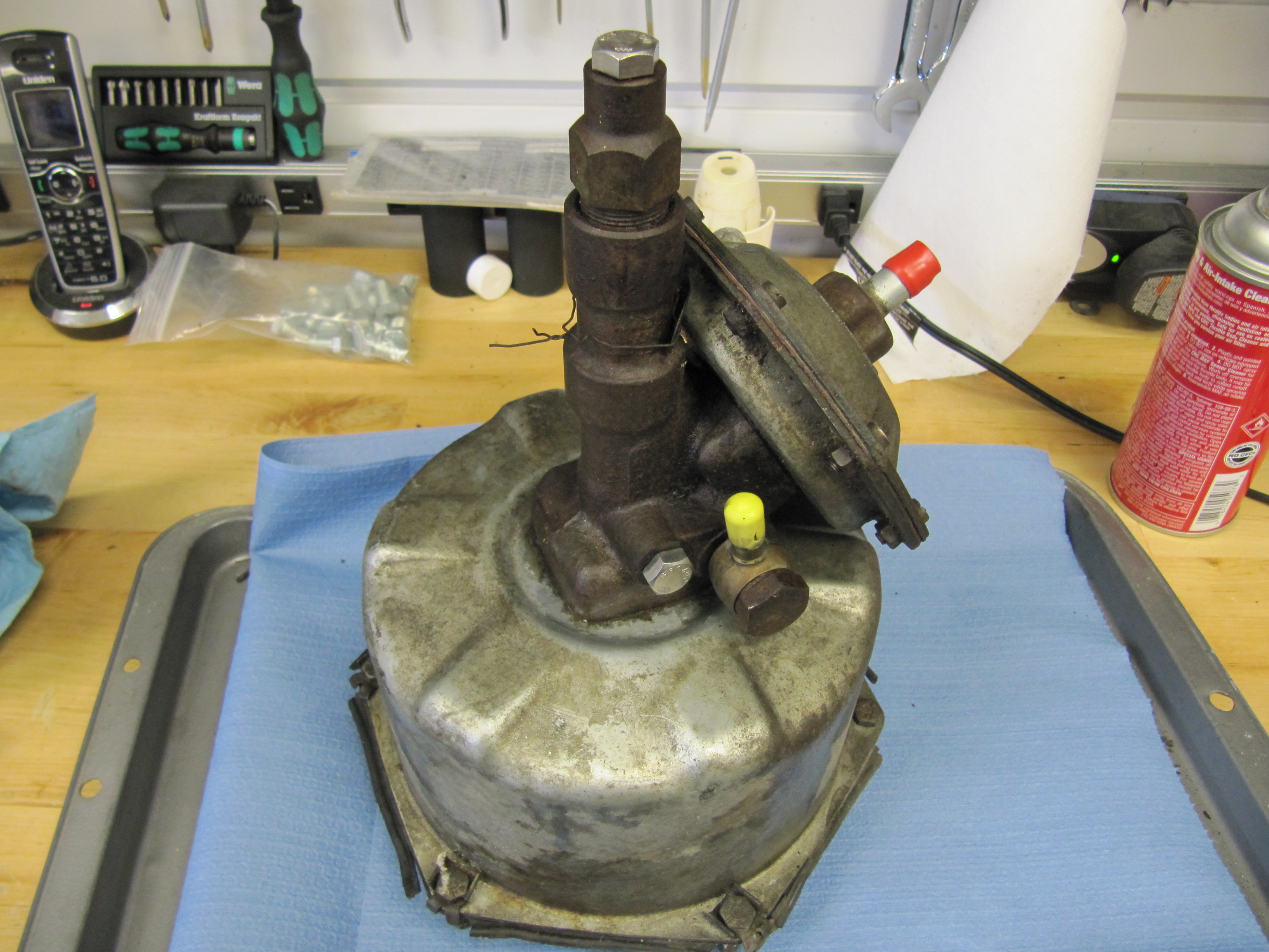
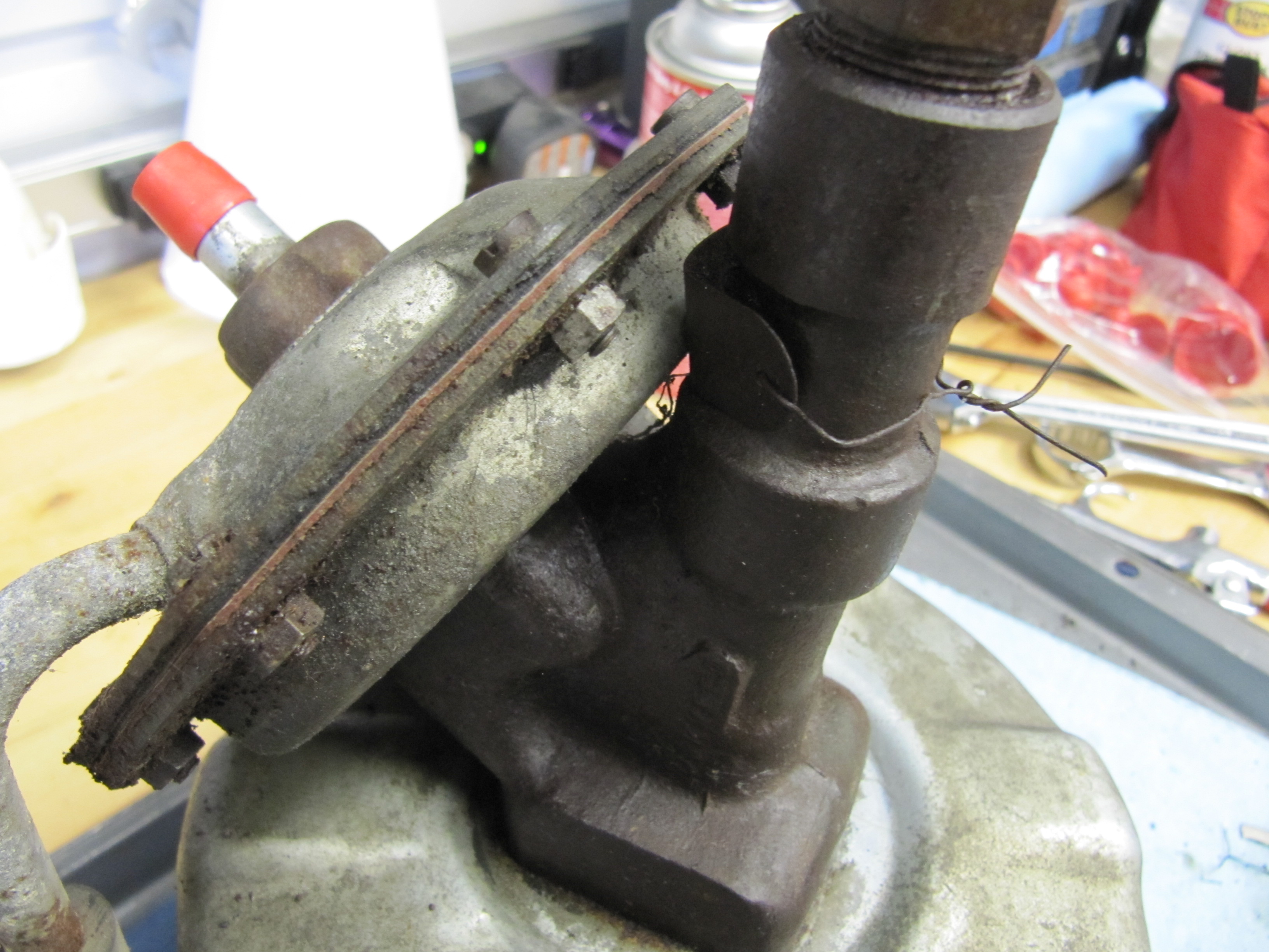
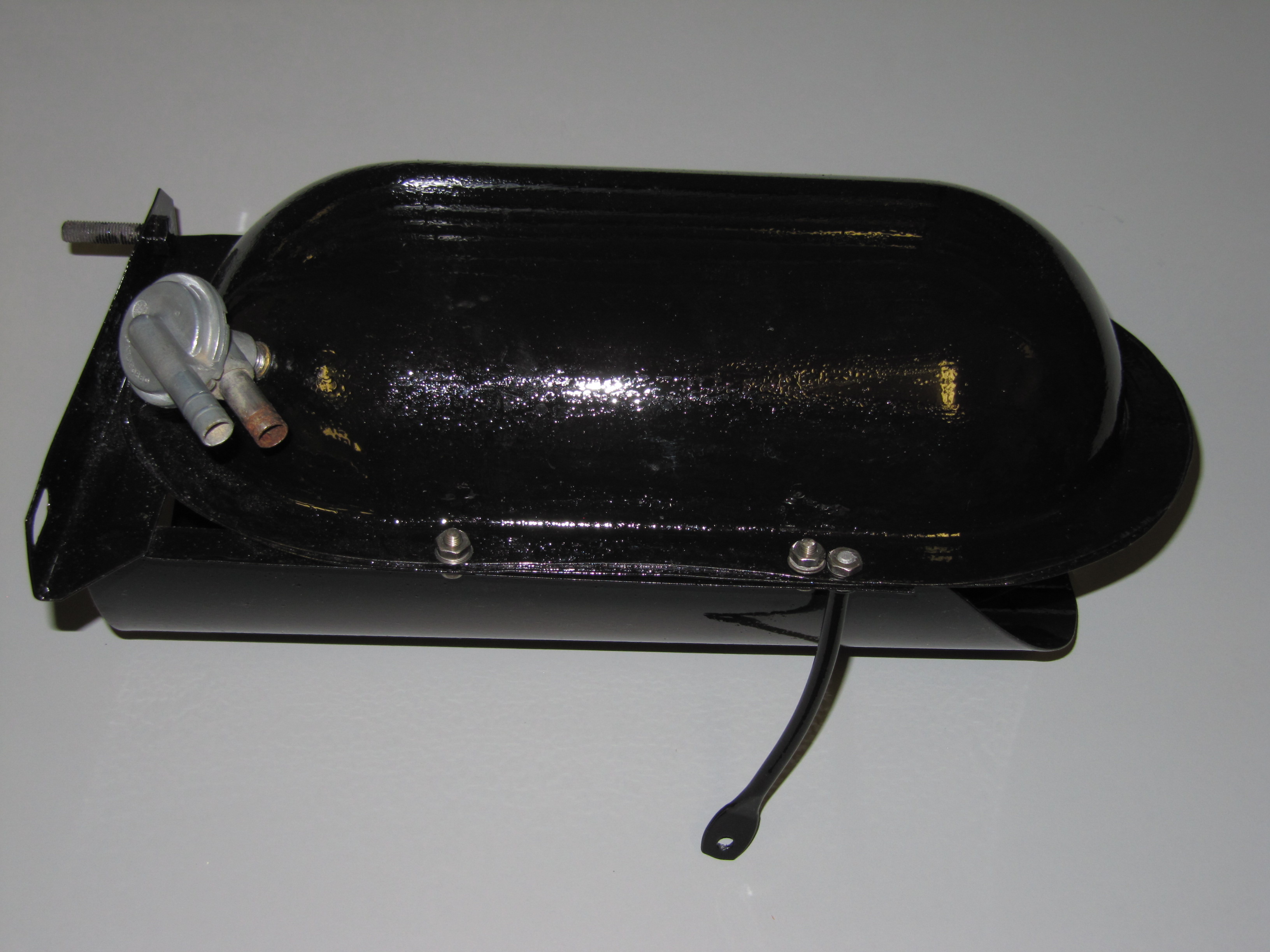
I then mounted the Reservac vacuum tank. It mounts to the body with two 5/16″-24 x 3/4″ hex bolts, flat and shake proof washers and nuts. A small brace arm connects the vacuum tank to the cowl for additional support.
Brake Booster Cowl and Vacuum Tank Mounted
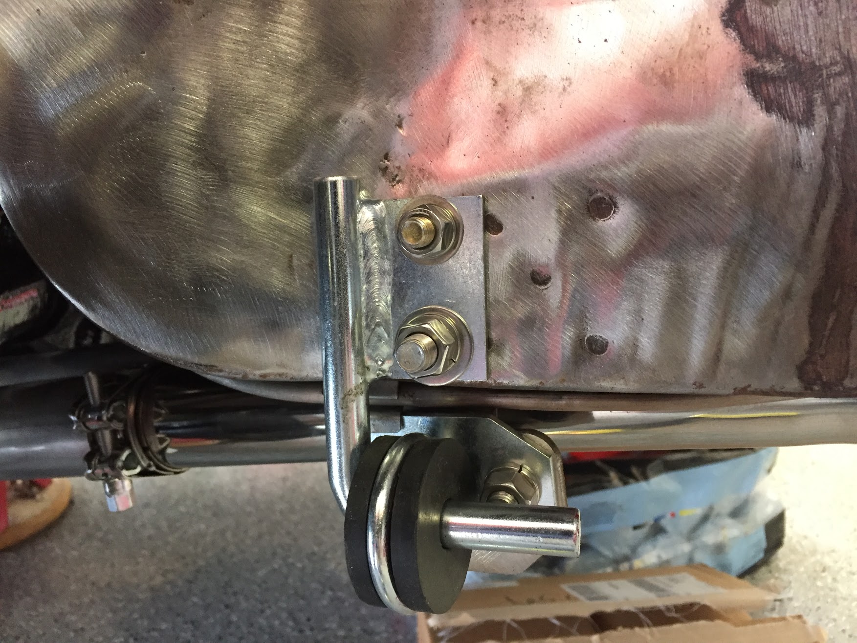
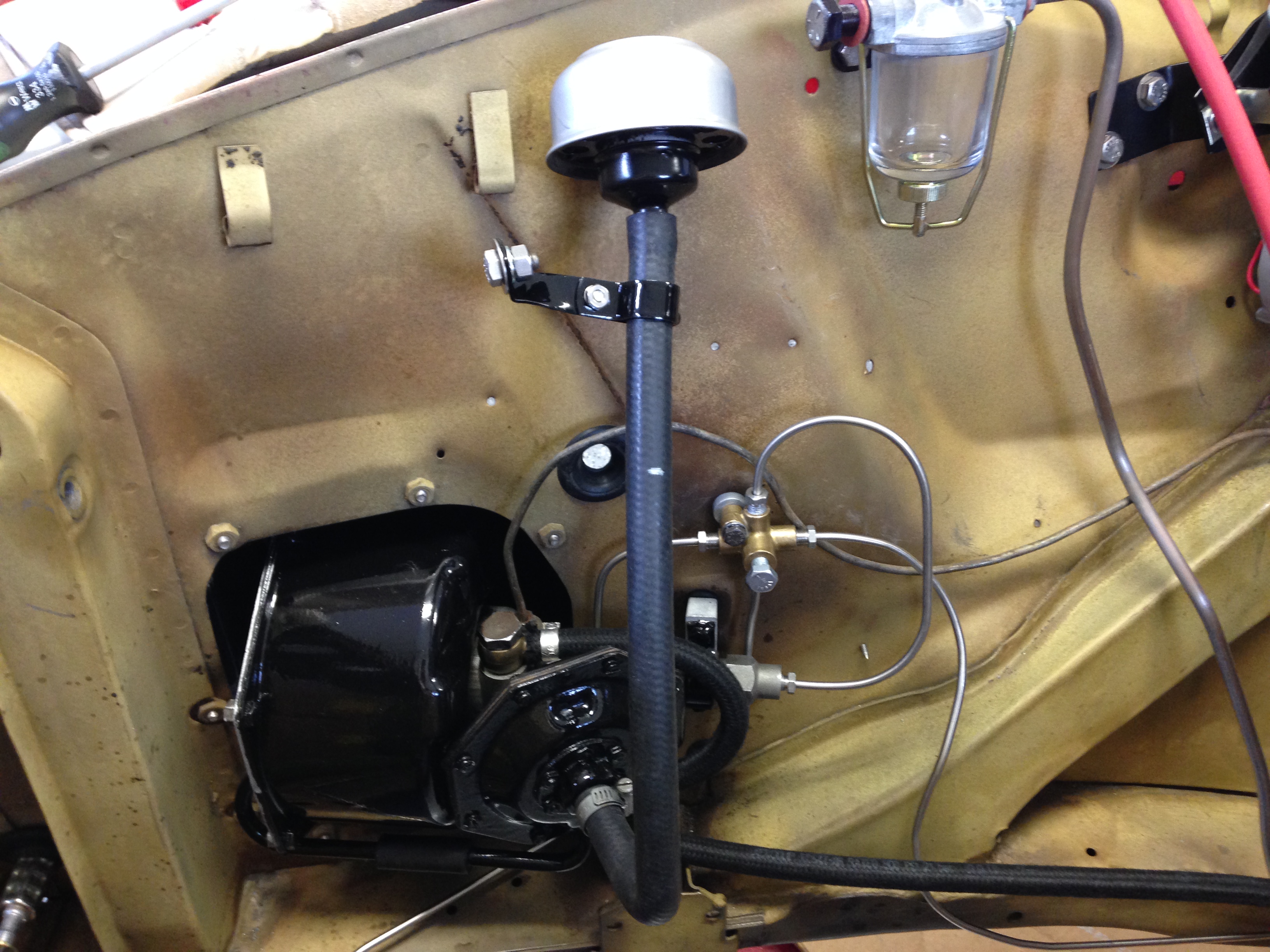
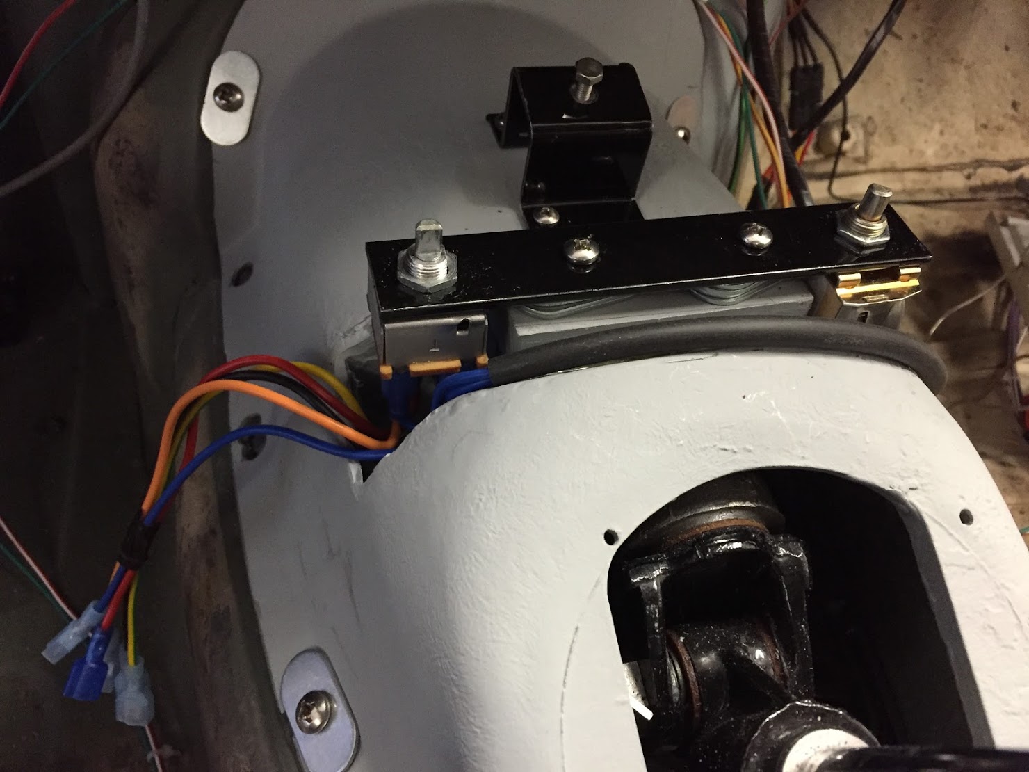
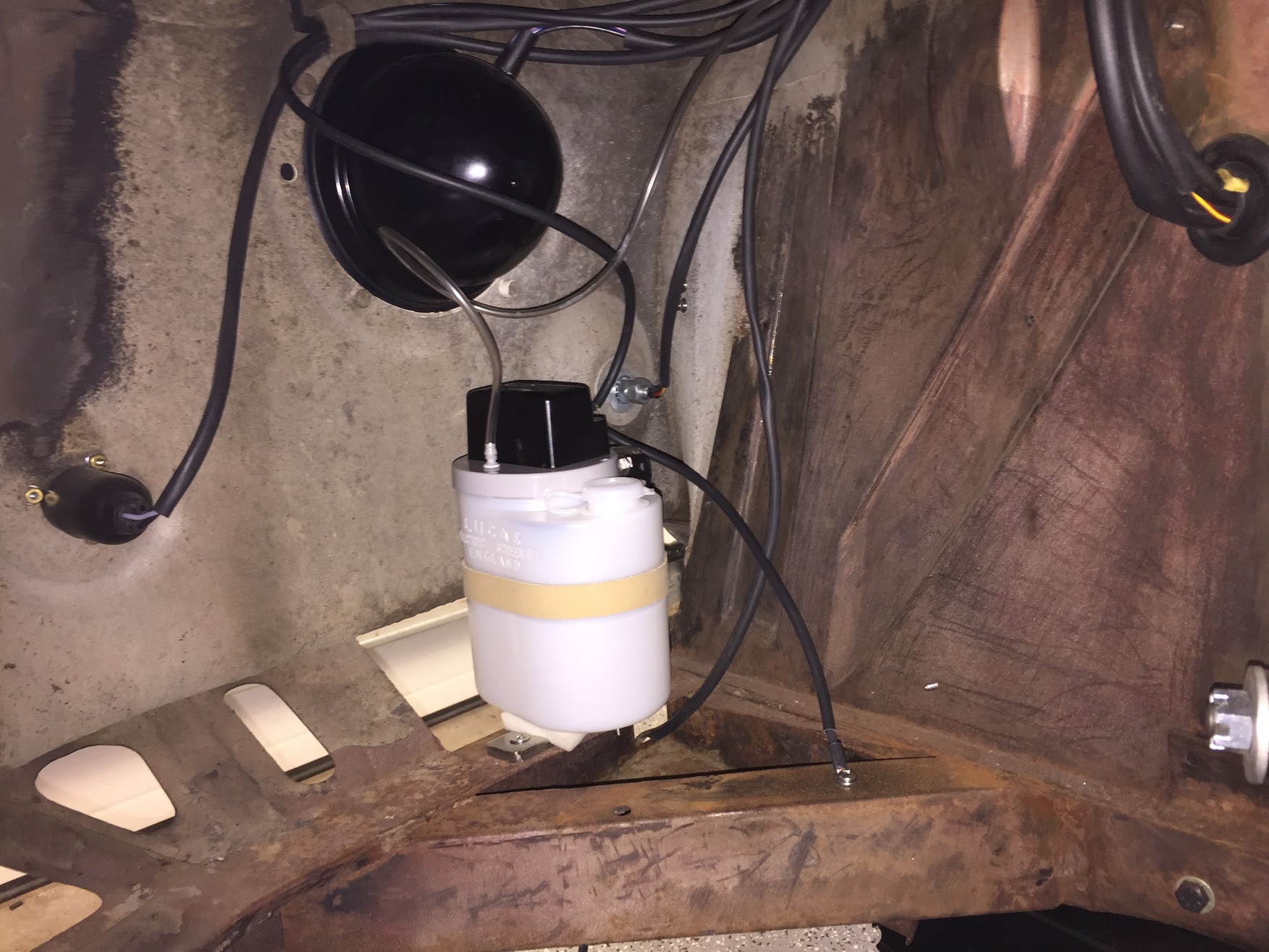
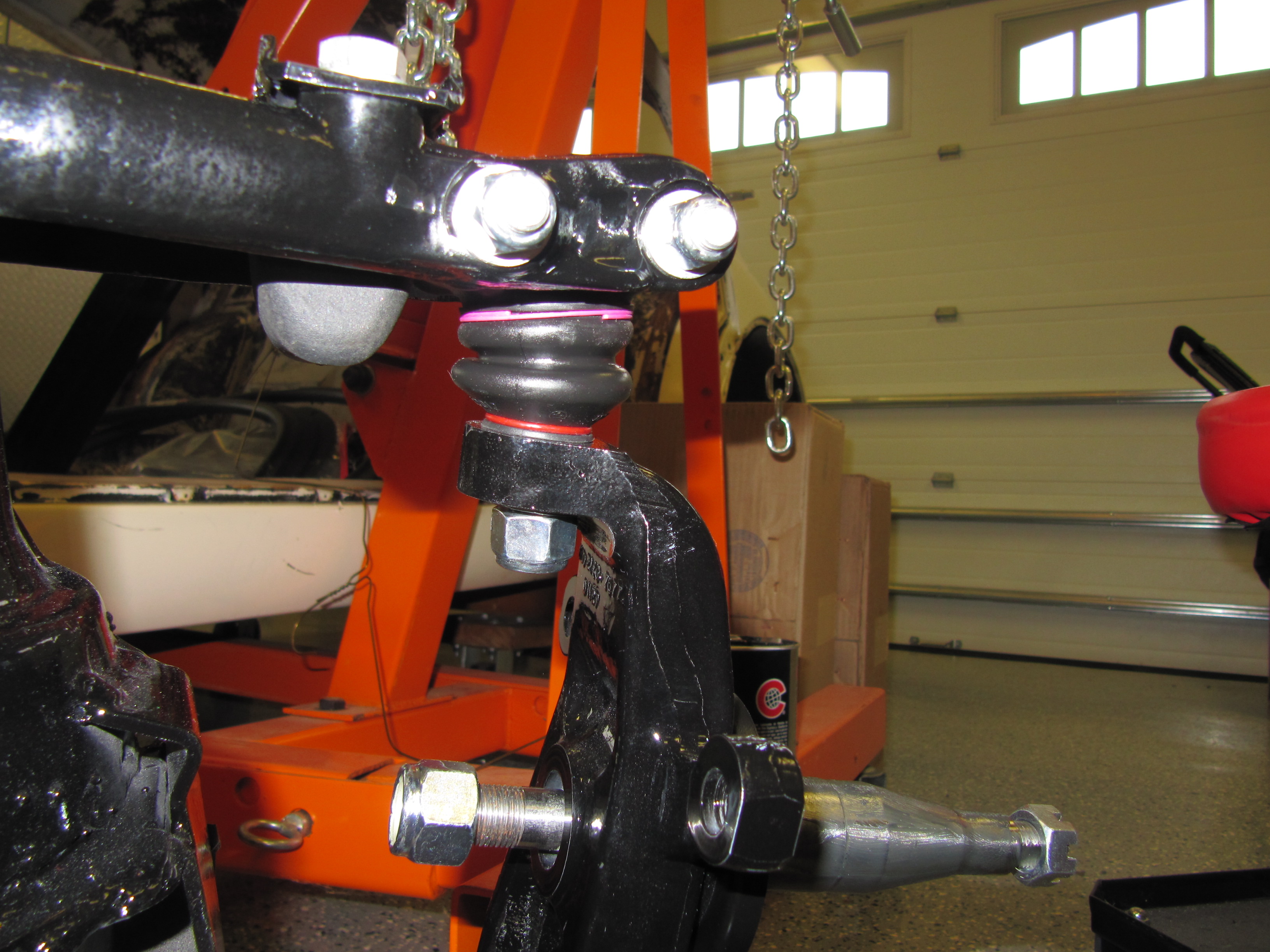
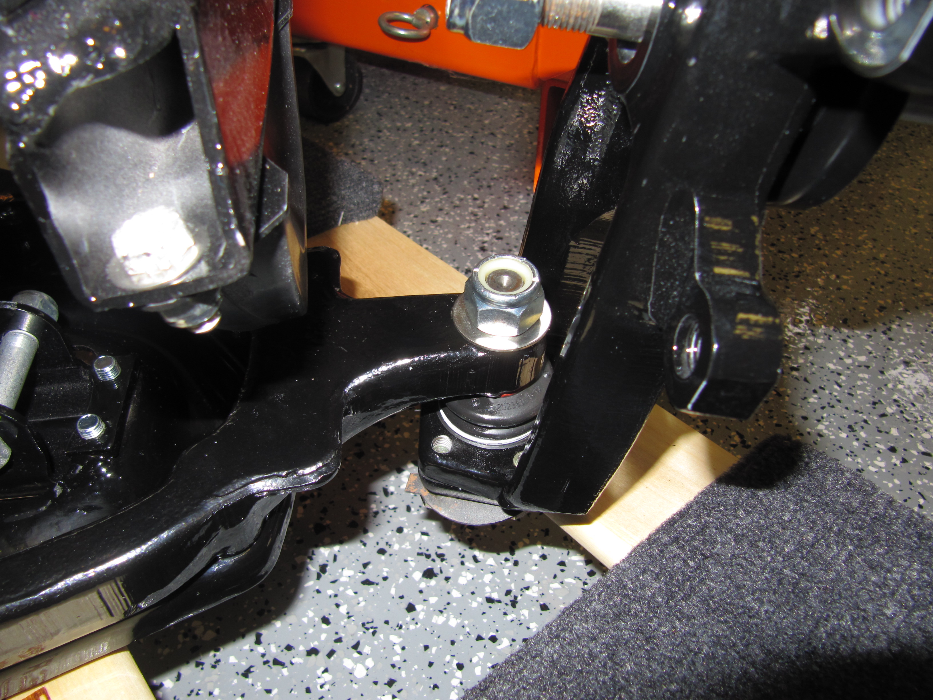
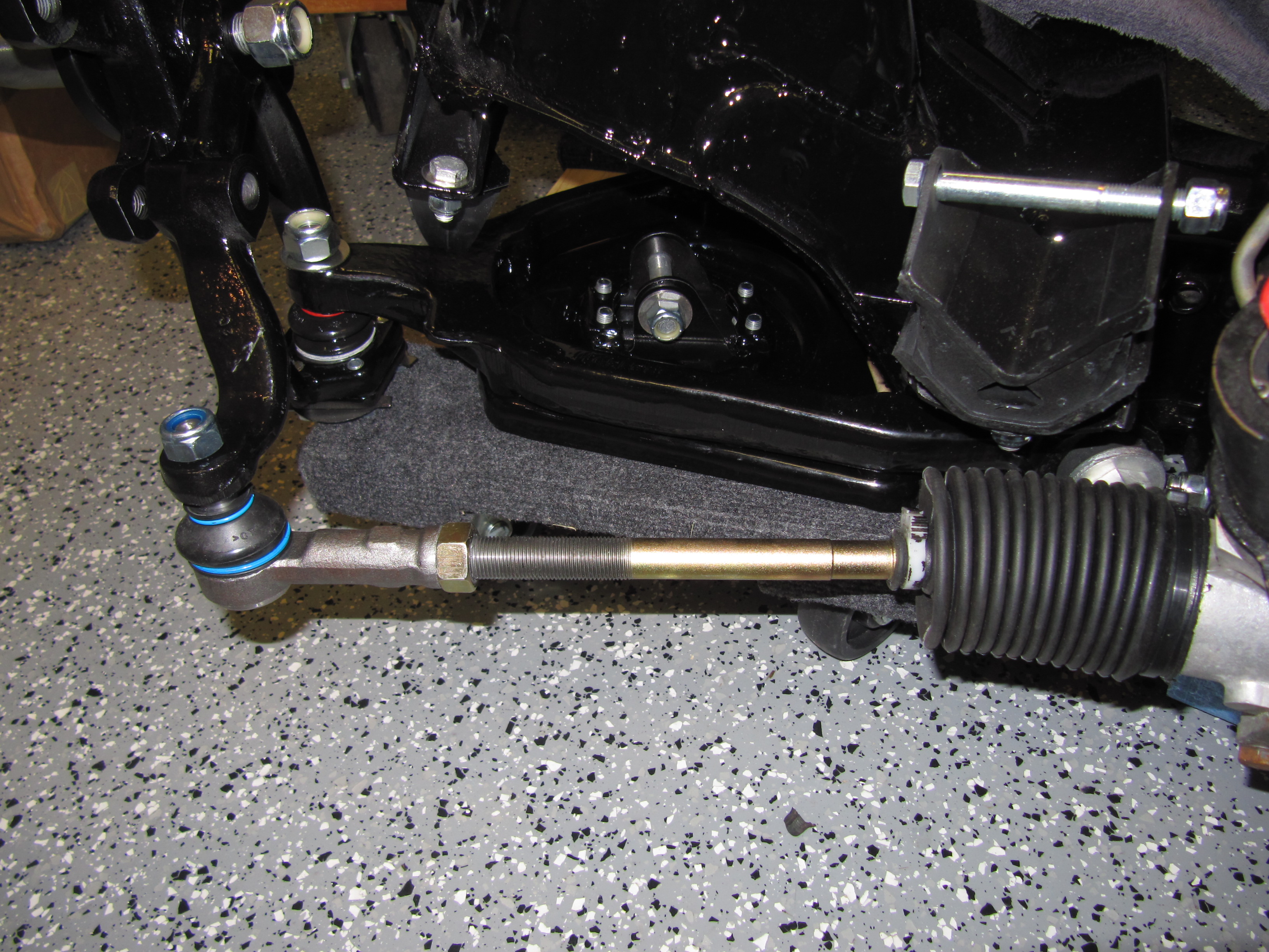
I installed the front suspension crossmember and the uprated windscreen wiper motor sourced from Classic Motor Cars http://www.classic-motor-cars.co.uk/servicing_types/mk2-lorem/. It requires a different mounting location than the original Lucas motor. With everything in place I was able to place the drier bracket without any worries.
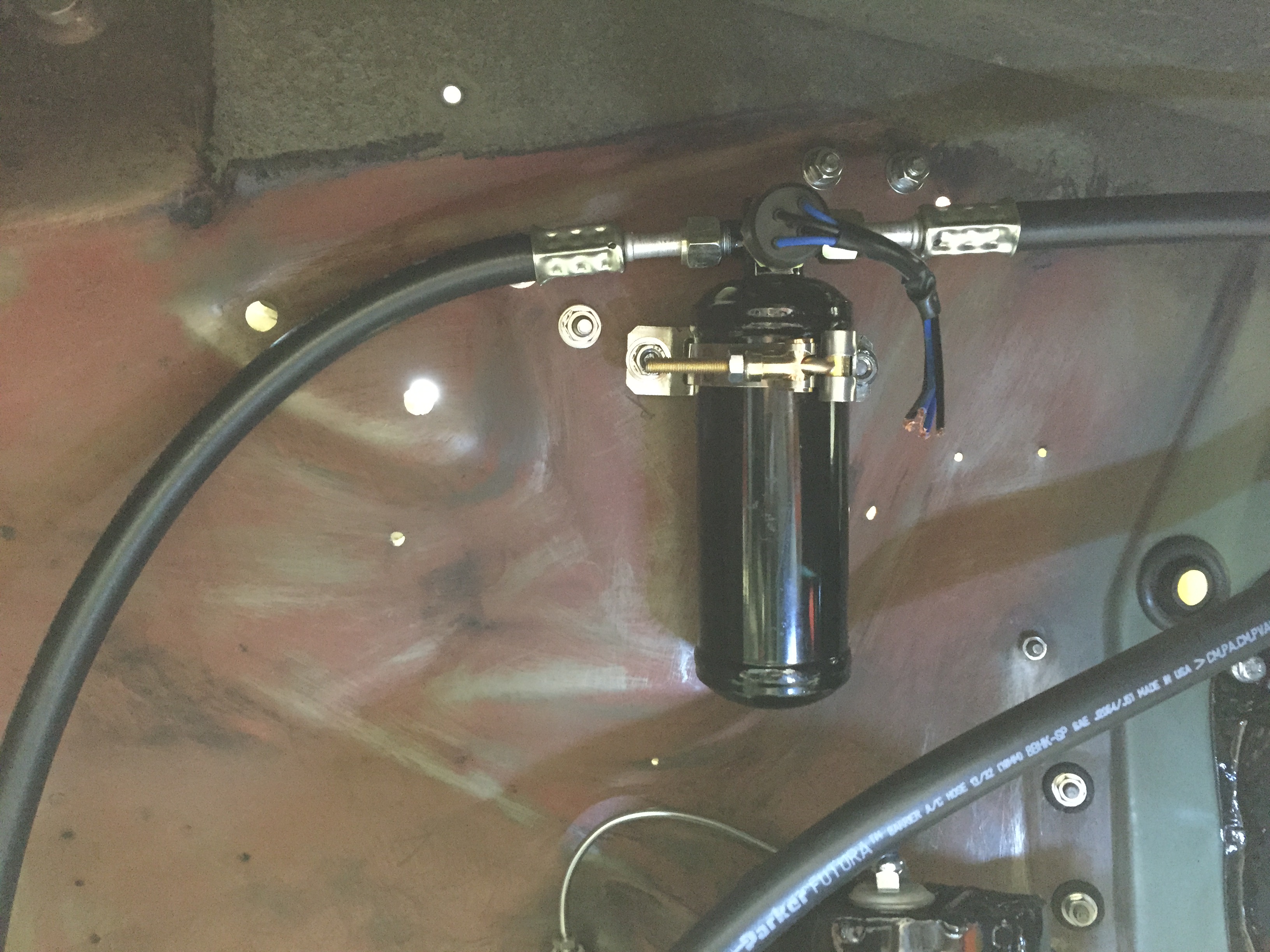
I used a Moroso tank bracket to mount the drier: http://tinyurl.com/kdjbovw it was purchased from Summit Racing. I used two 5/16″ – 24 x 1 1/2″ with nylock nuts and flat washers for the mounting. The drier was supplied in the Retro Air kit.
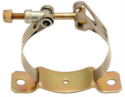
Moroso Drier mounting Bracket

Air Conditioning Drier Installed
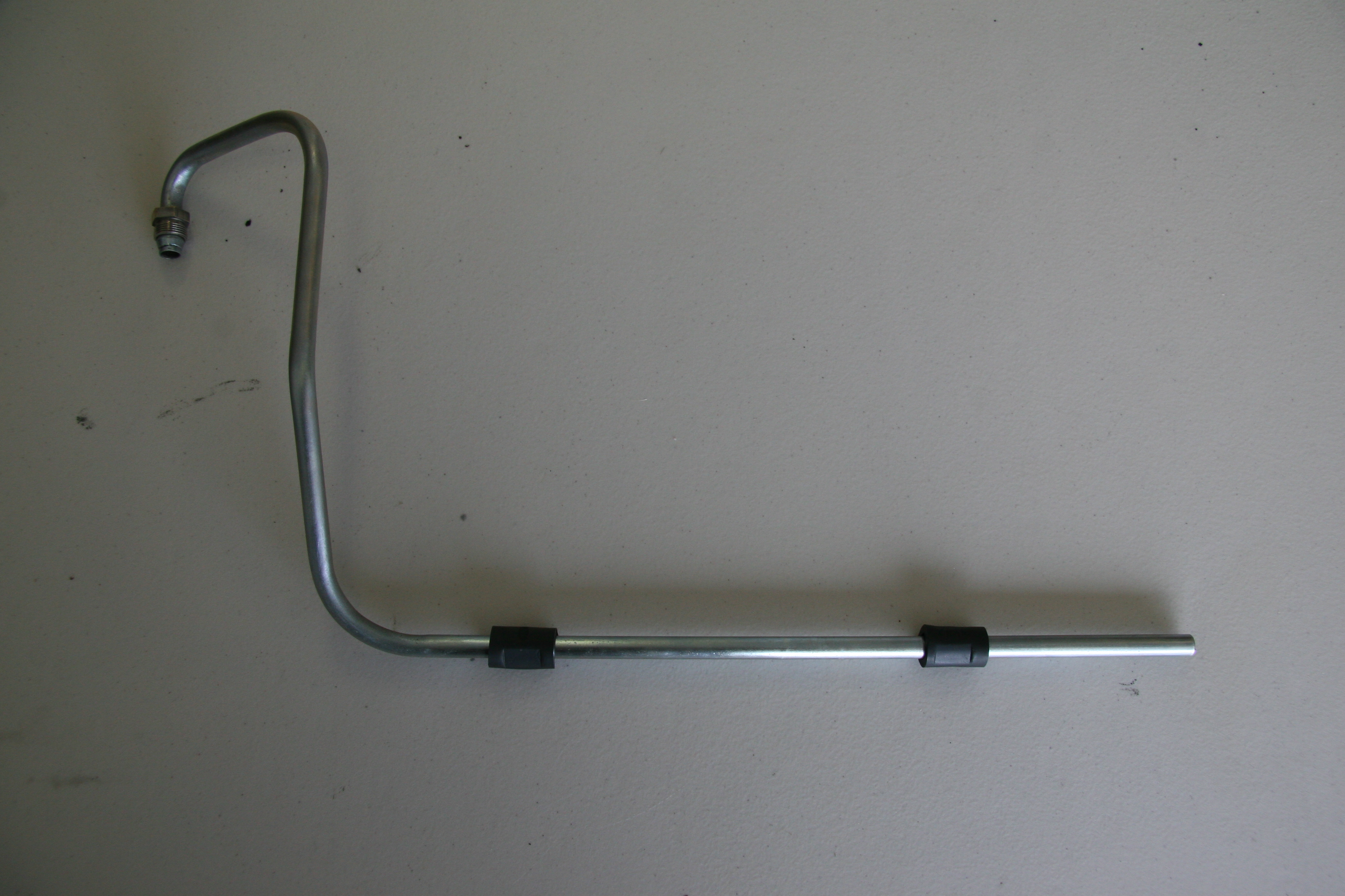
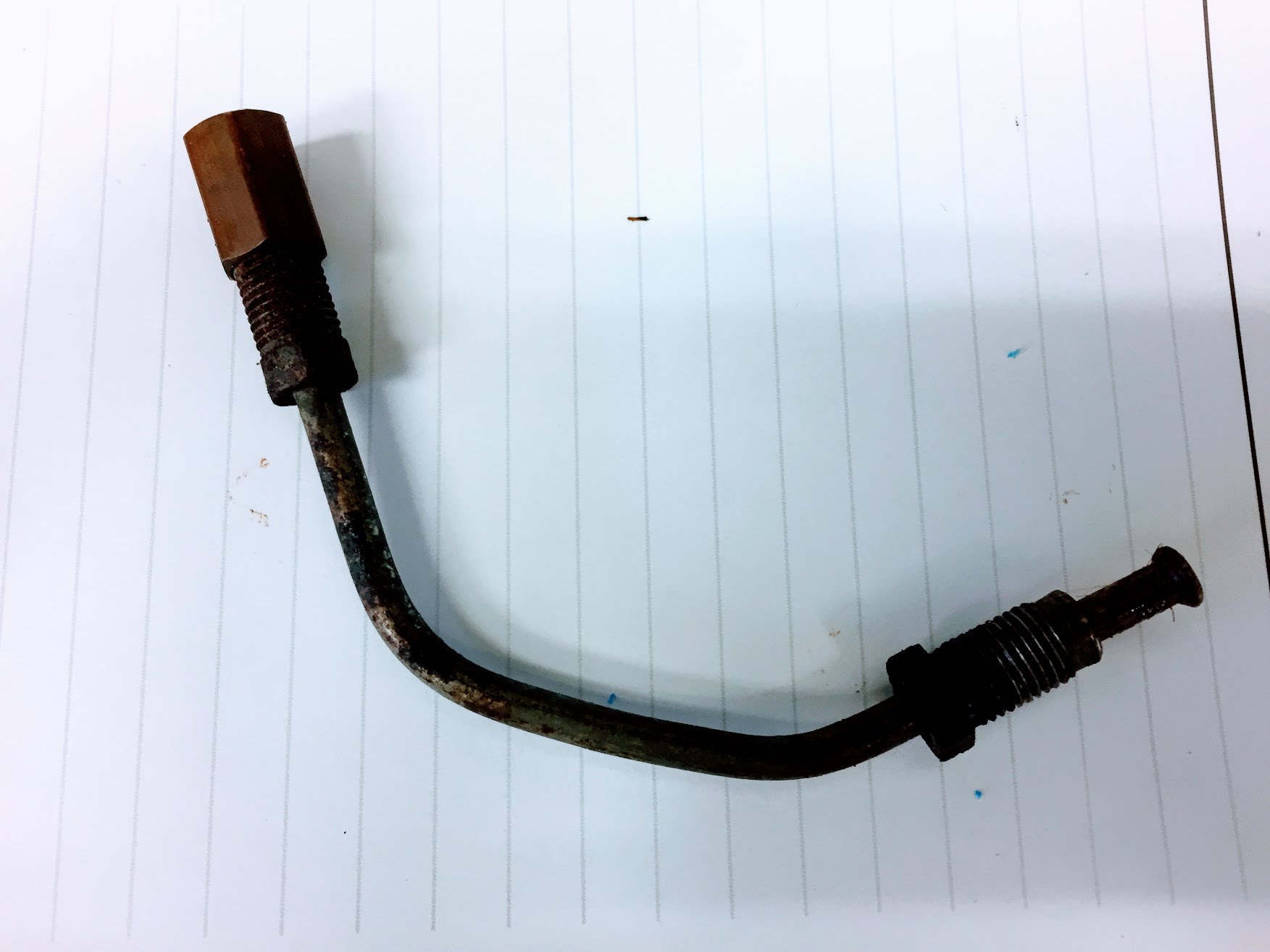
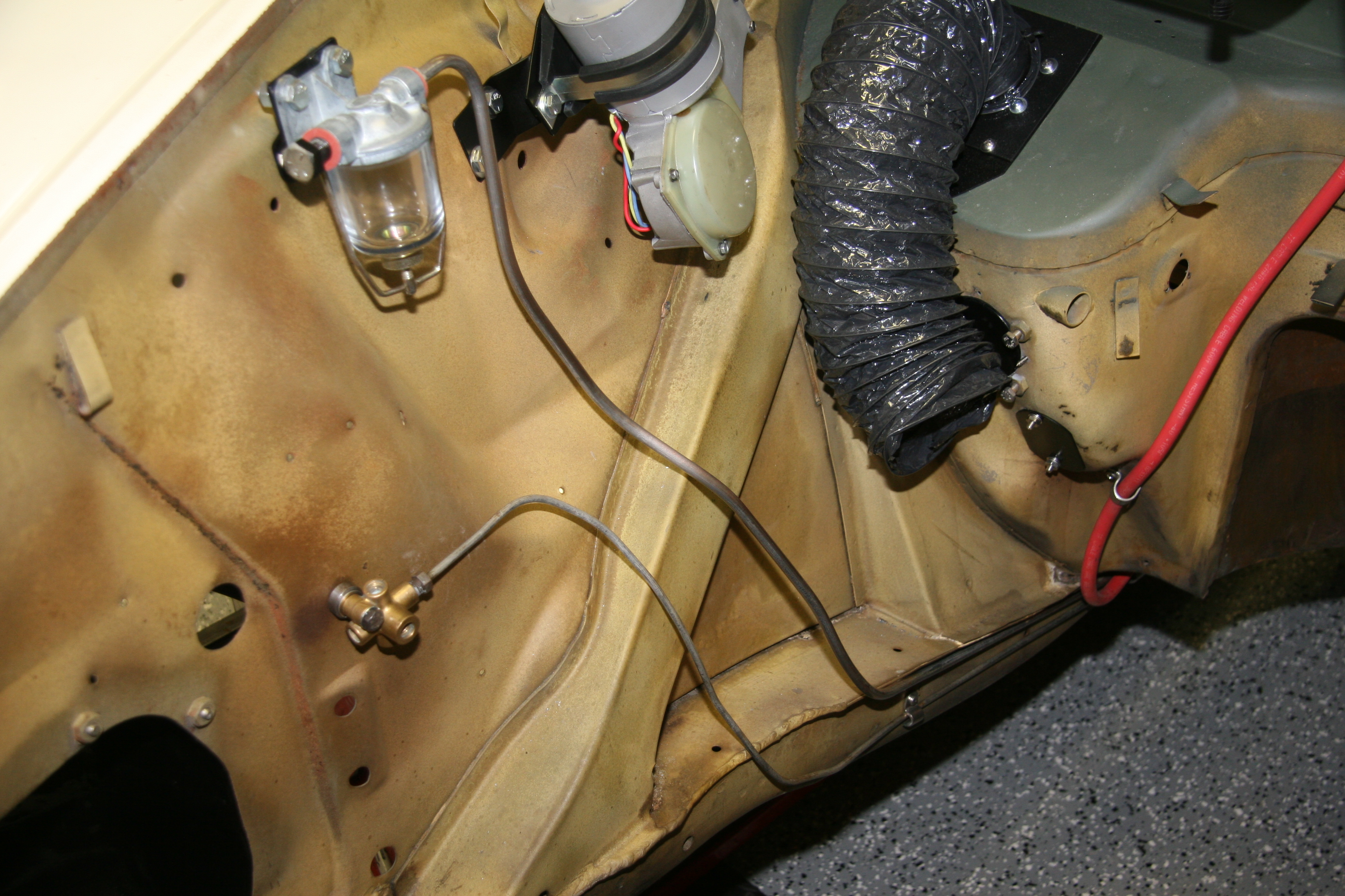
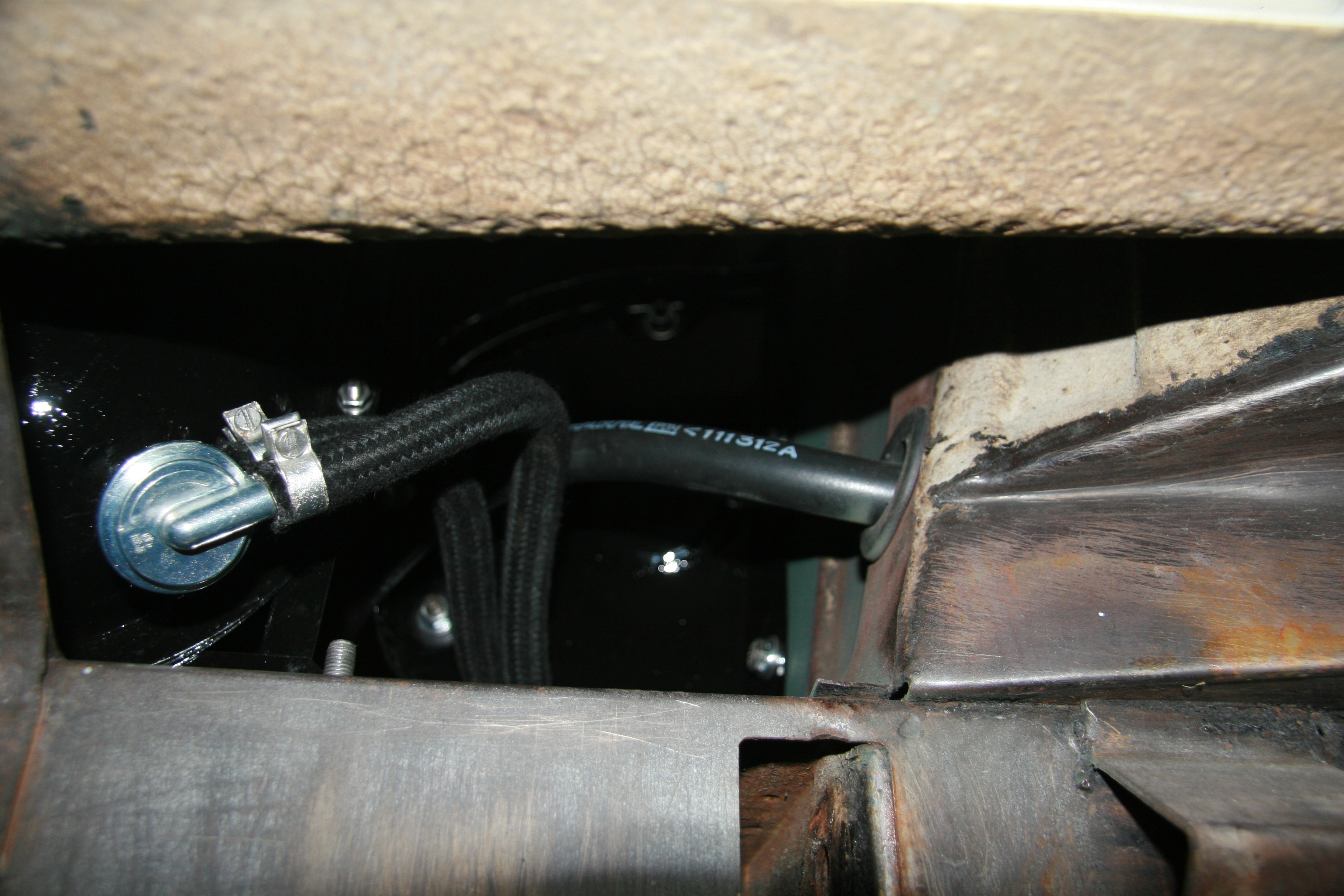
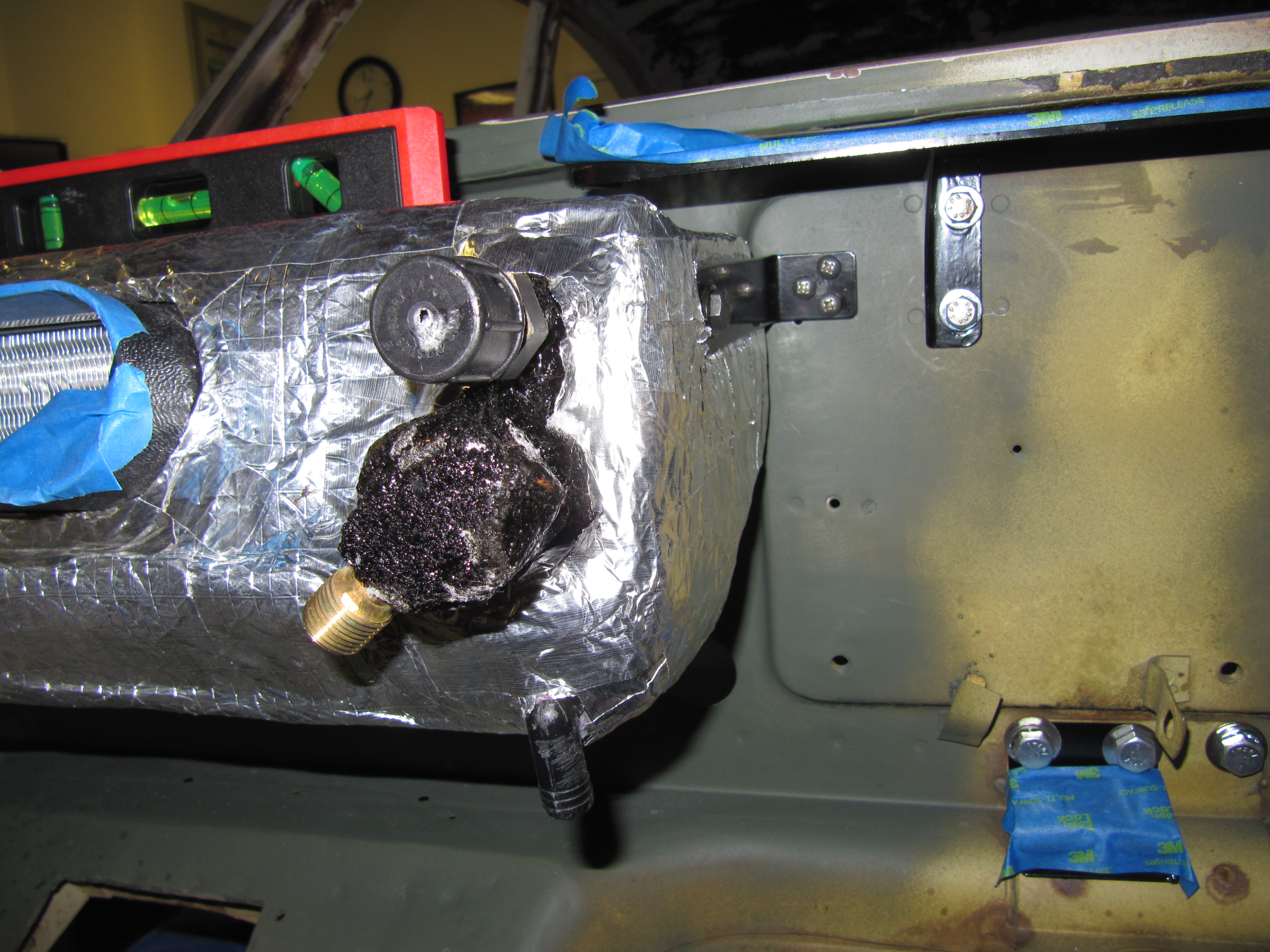
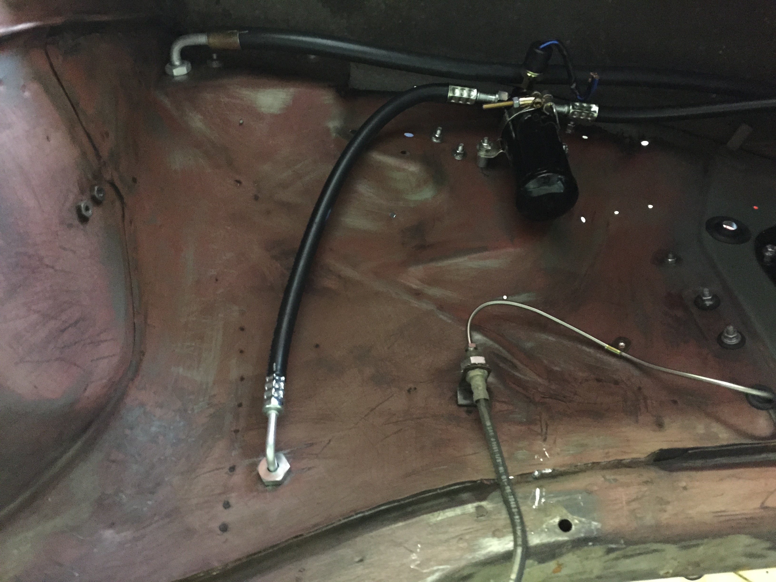
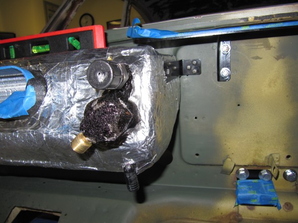
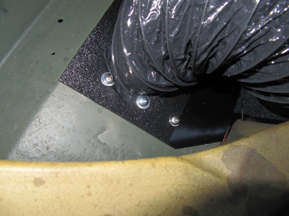
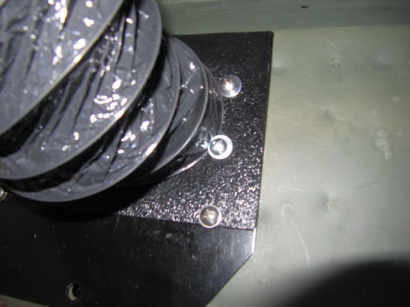
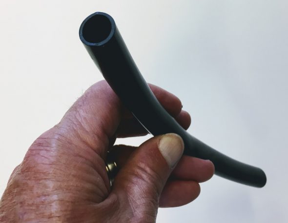
The remaining #6 hose supplied in the RetroAir kit is used to connect the drier to the evaporator. Again, I departed from the RetroAir instructions and installed a hard 90 degree fitting through the valance to route the hose to the evaporator. I just don’t like running the hose through a grommet in the valance wall. My approach also allows for a much tighter fit of the hose against the valance wall – no wide bends.
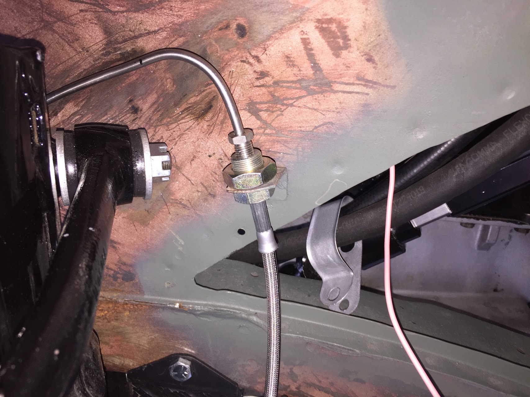
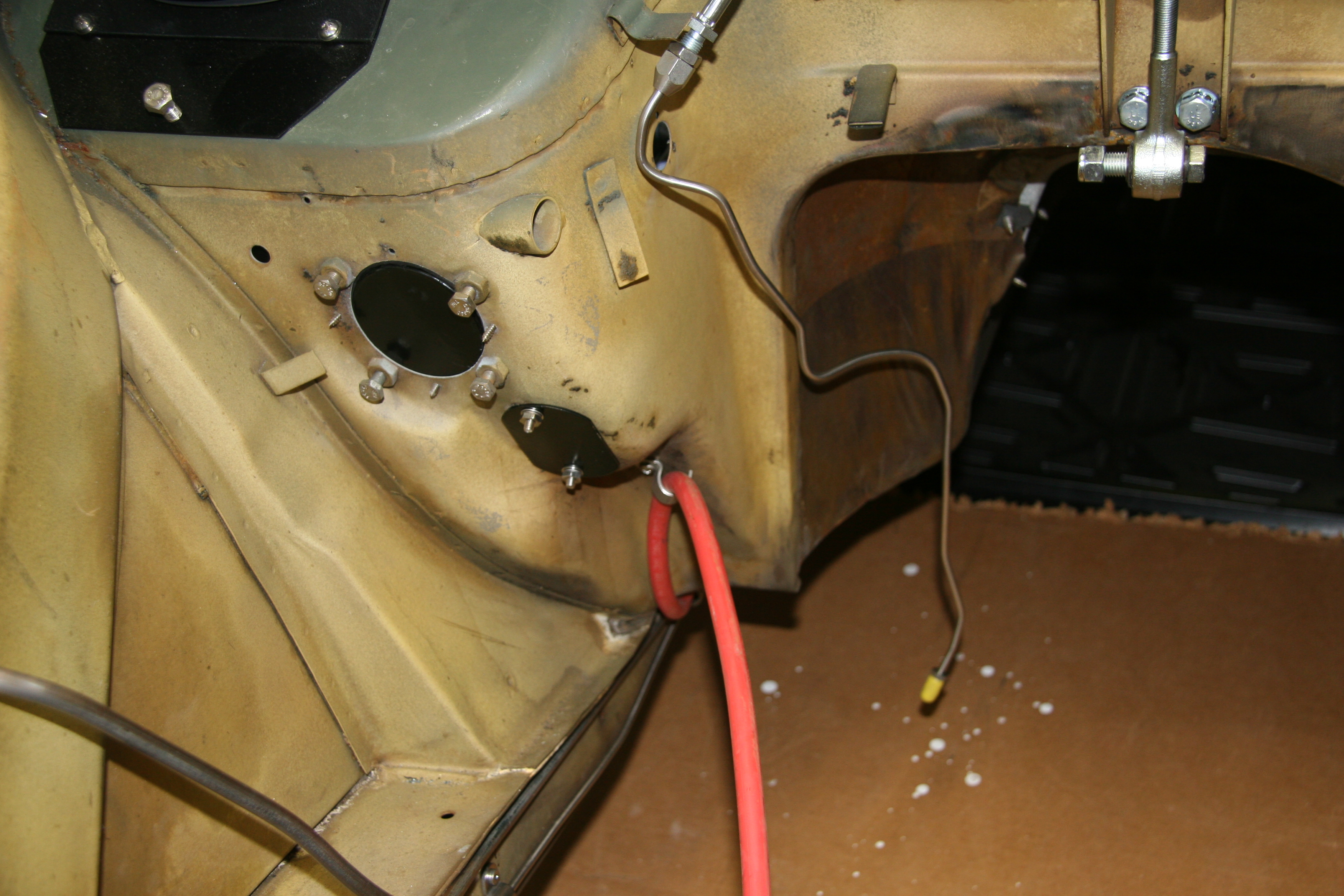
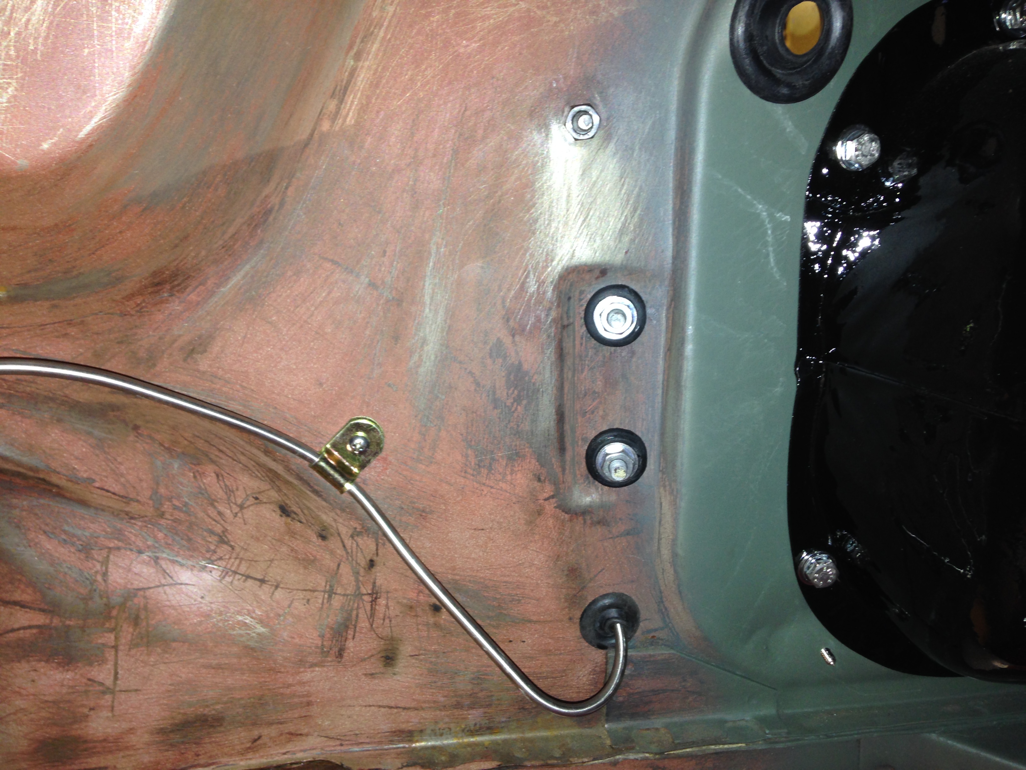
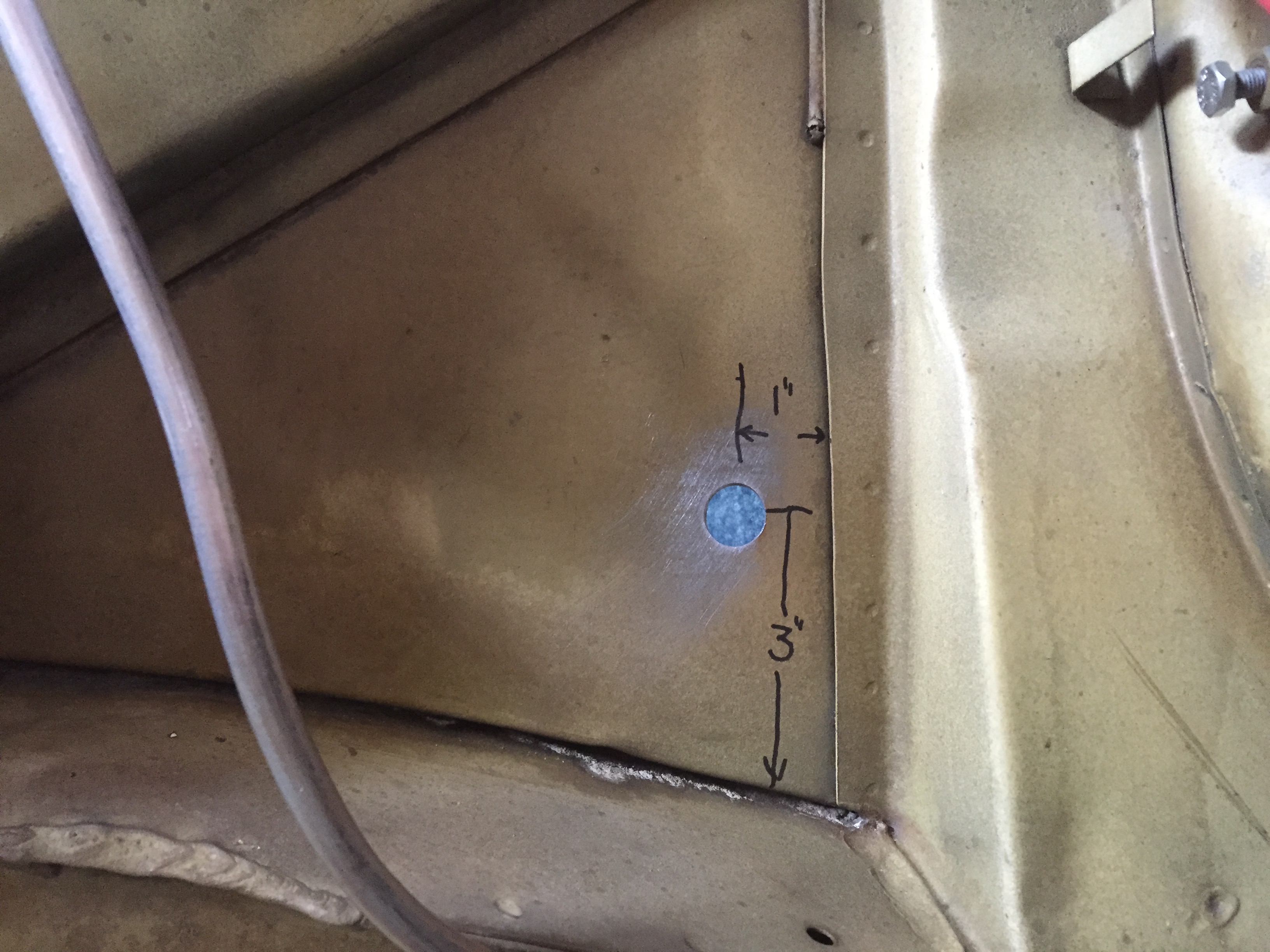
Also unlike the photos provided in the instructions I decided to mount the new fitting fairly low on the flat triangular panel at the rear of the valance and then run the hose vertically to the evaporator inside the engine bay. I used a stepped drill bit to drill a 5/8″ hole in the valance for the hose fitting. The measurements are approximate. Using the hard fitting did require cutting the kit supplied hose. I did need to purchase additional #6 hose to use on the inside of the engine bay valance from the new fitting to the evaporator.
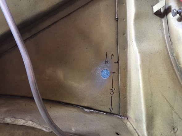
Location of Hose Fitting Hole in Valance
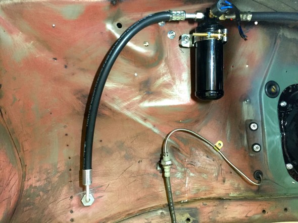
Installed #6 Hose from Drier to Fitting in Valance
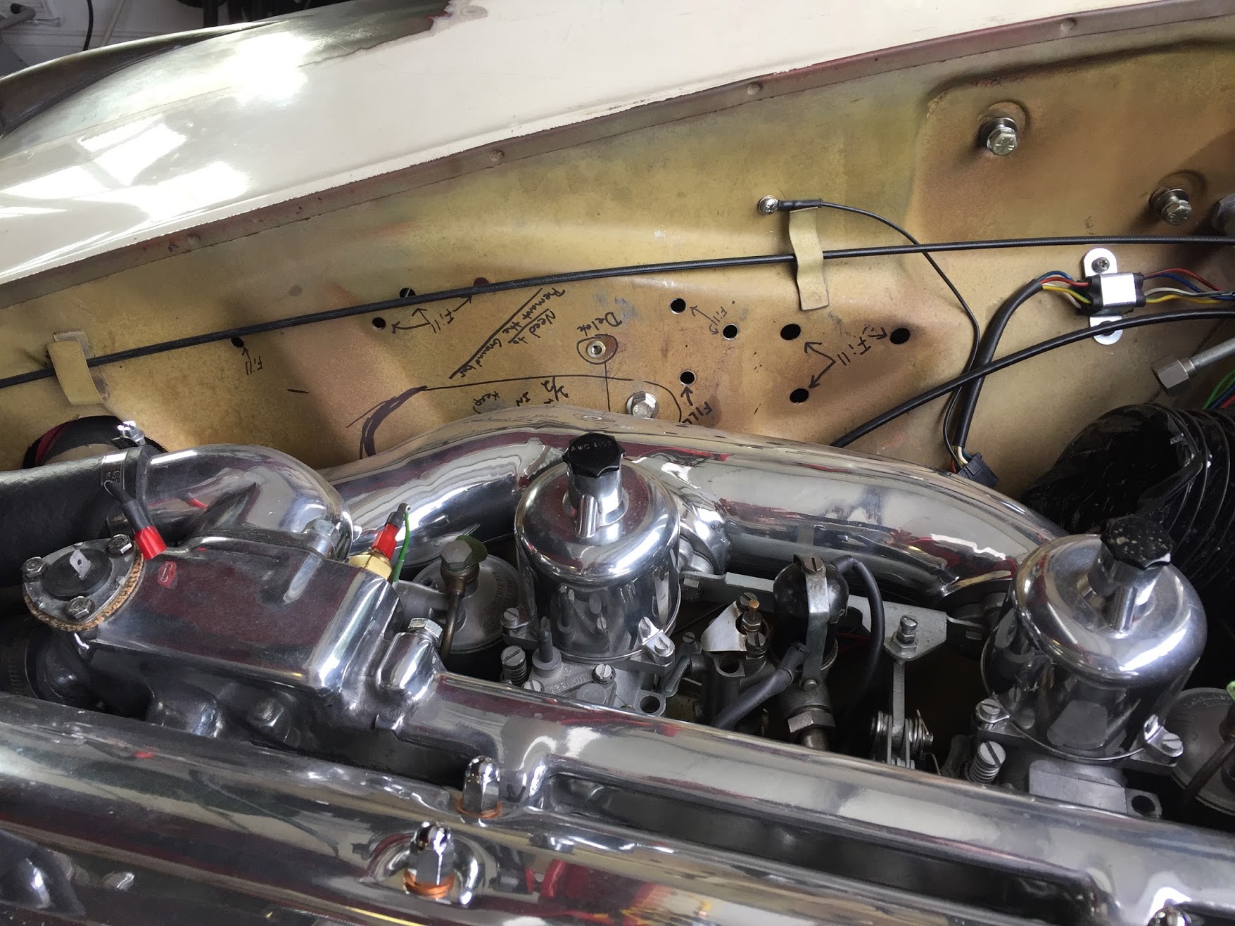
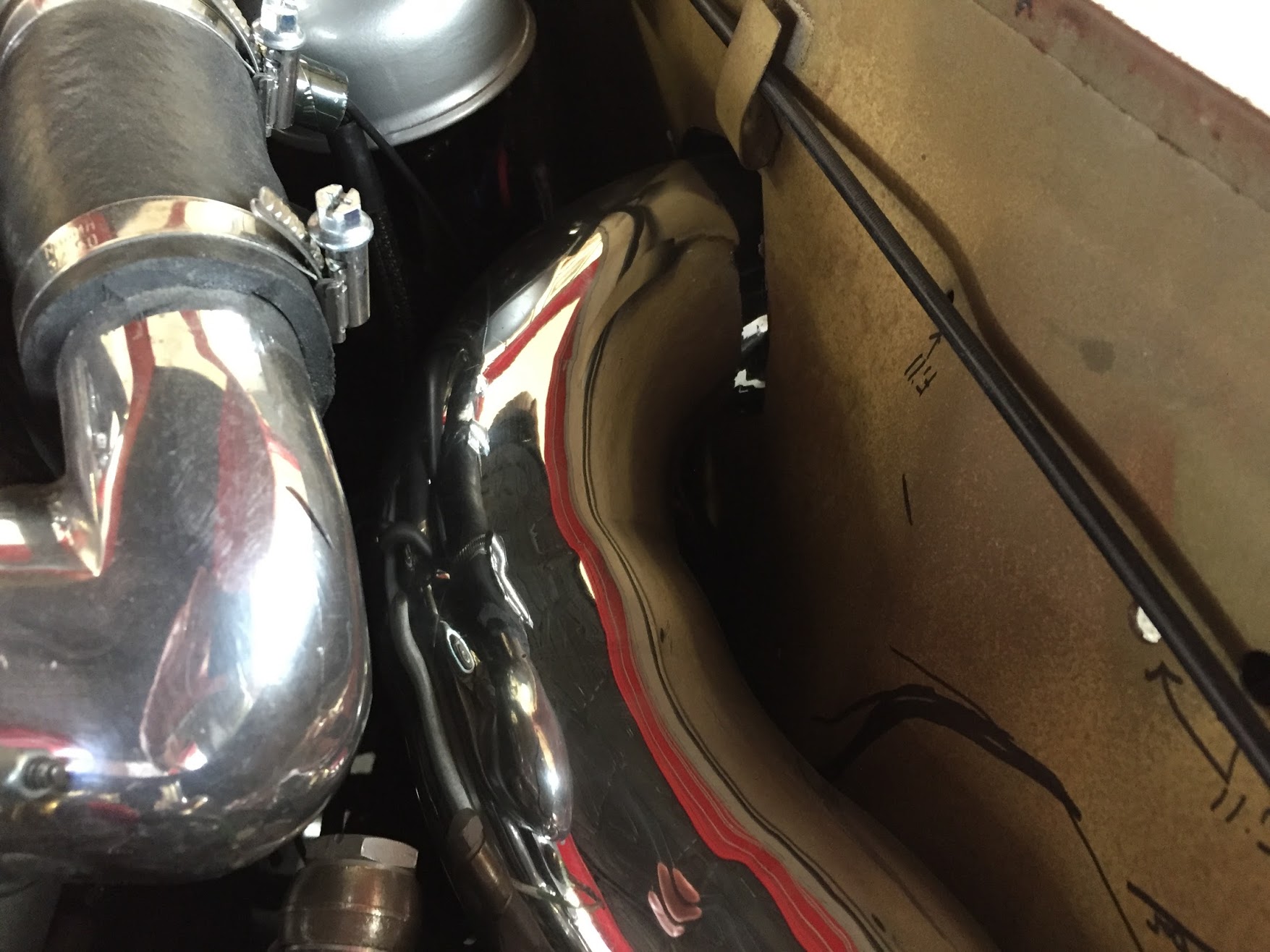
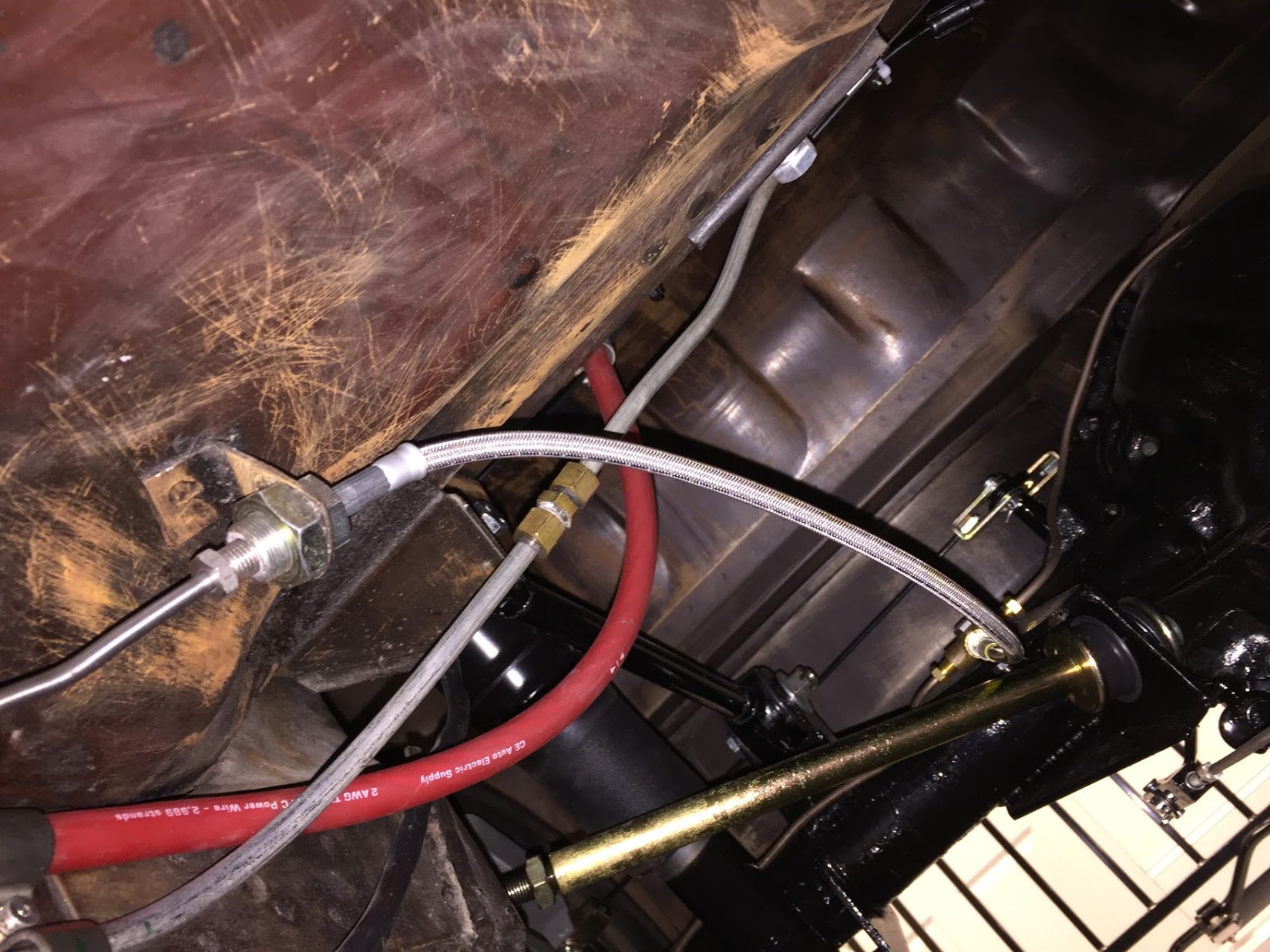
This image shows the final mounting and routing of the hoses from the condenser along the RH valance wall. Nice tight fits with nothing rubbing or sagging.

RH Valance Hose Routing
And the image below shows the engine bay side of the installation, from the valance to the evaporator:

#6 Hose from RH Valance to Evaporator
The final hose, the #8 hose from the evaporator to the compressor (seen in the image above to the upper right), was fit to the evaporator; however, the final length of the hose will be determined once the engine and compressor are installed.
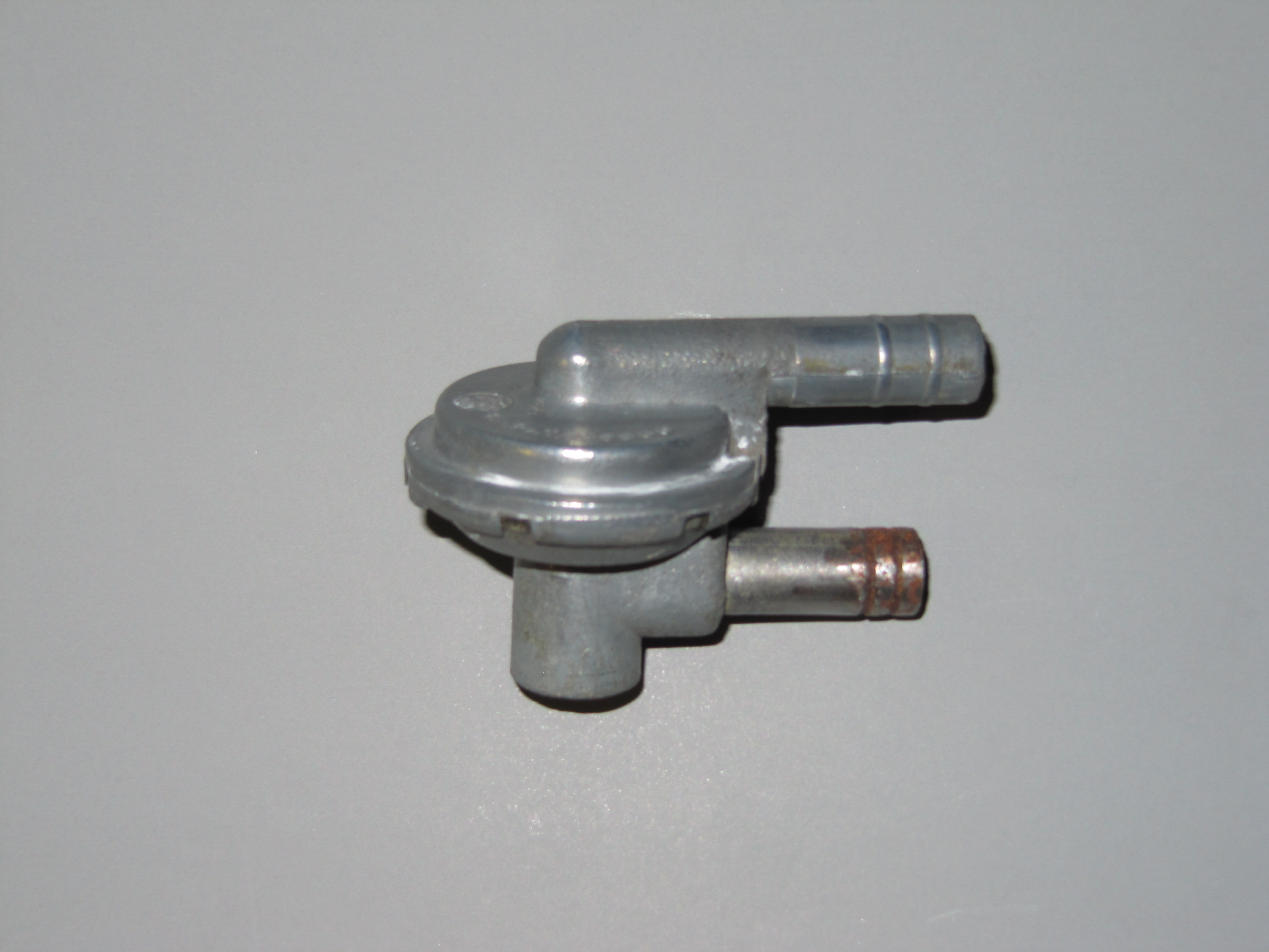
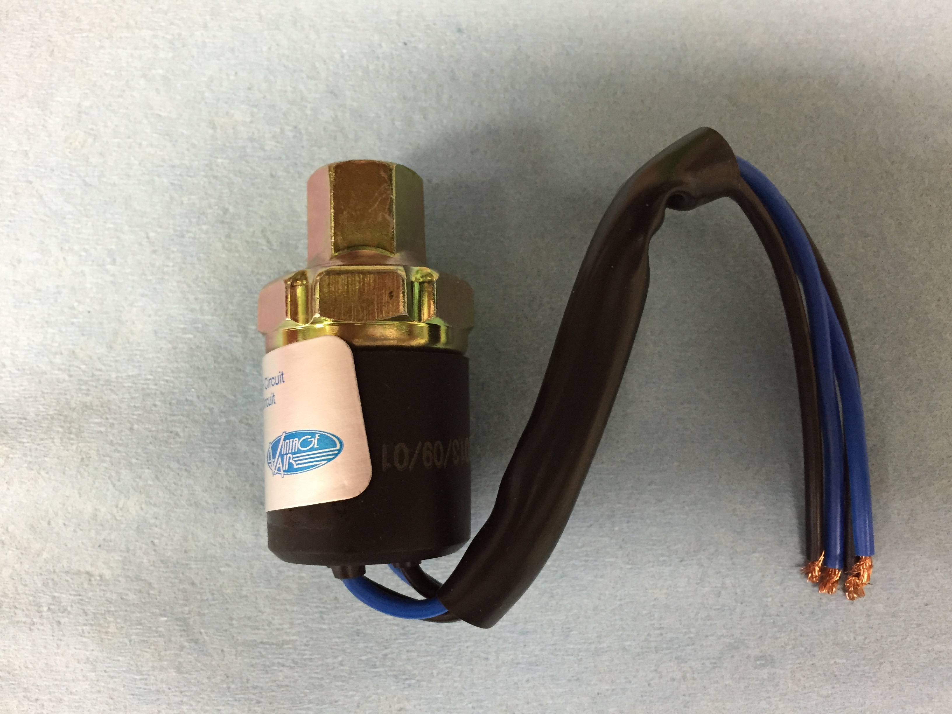
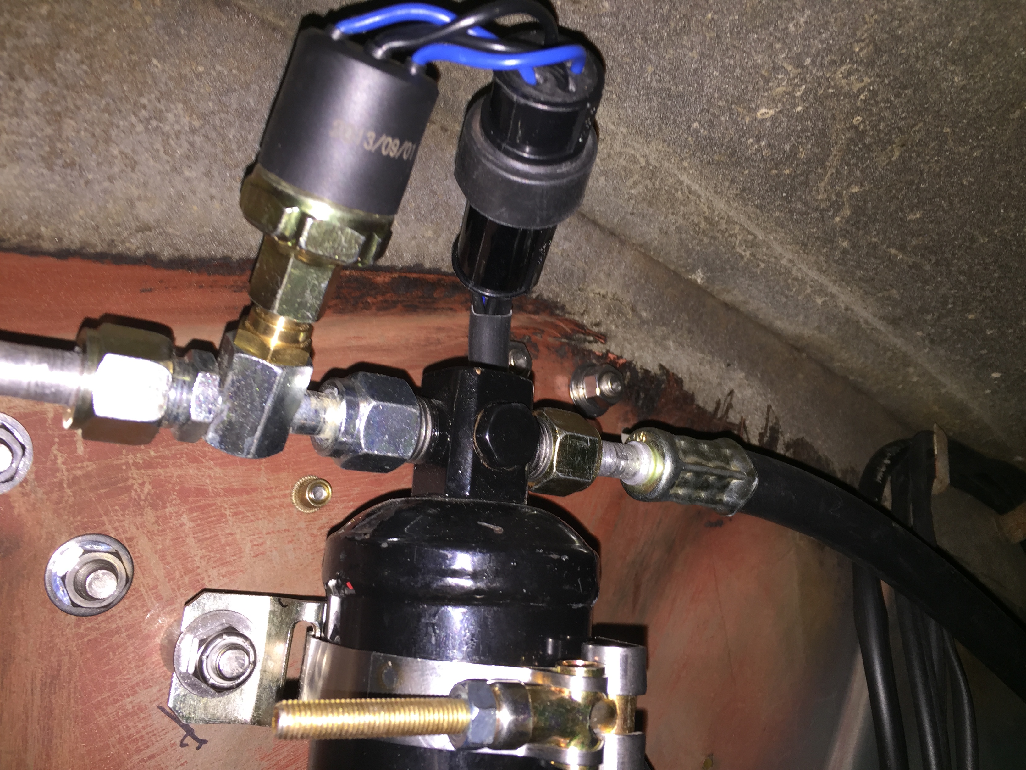
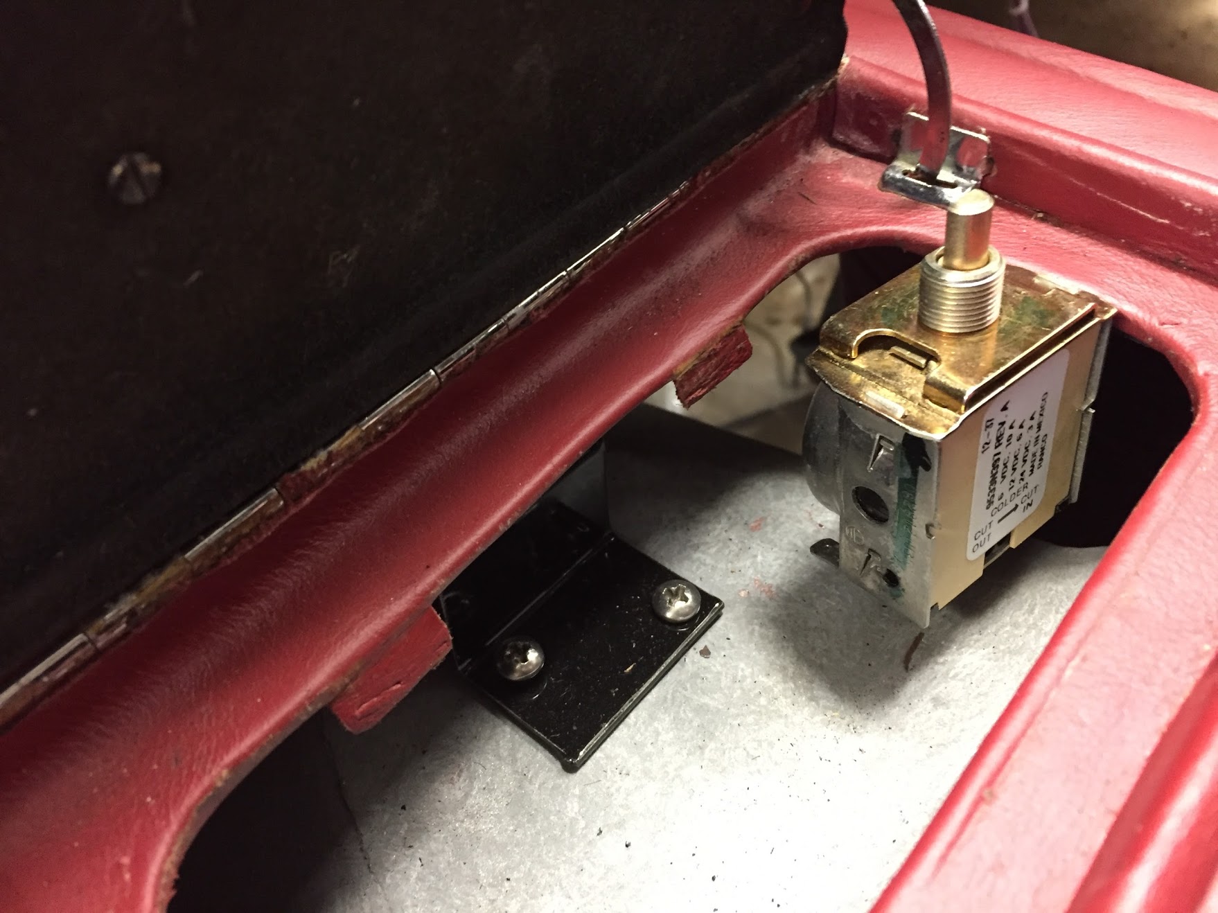
Trinary Safety Switch
The Retro Air kit included a binary switch, but I decided to use a trinary switch. The Vintage Air trinary switch kits combine low and high pressure compressor clutch cut-off functions plus an electric fan engagement signal at 254 psi. The low pressure cut-off of these trinary switches is 30 psi and the high pressure cut-off is 406 psi.
http://www.vintageair.com/Instructions2013/904678.pdf
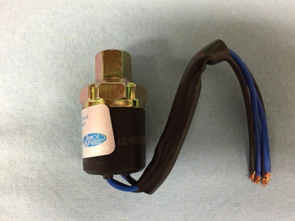
Vintage Air Trinary Switch

Vintage Air Trinary Switch
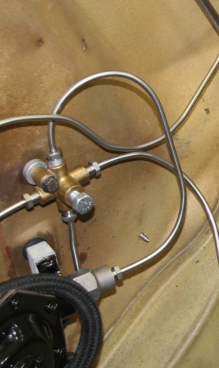
The switch is fastened to the drier via a “T” pipe allowing adjustment in the mounting of the switch.

Trinary Switch, Drier and Wiring Connector
There are four wires, two blue and two black, on the switch I purchased. The wiring is explained in detail in the “New Wiring Harness Circuits” post.
British Wiring Waterproof Connector
I connected the four wires to a waterproof connector purchased from British Wiring. One blue wire is for ground and the other for fused power. One black wire connects to the compressor and the other to the thermostat controller for the air conditioner.
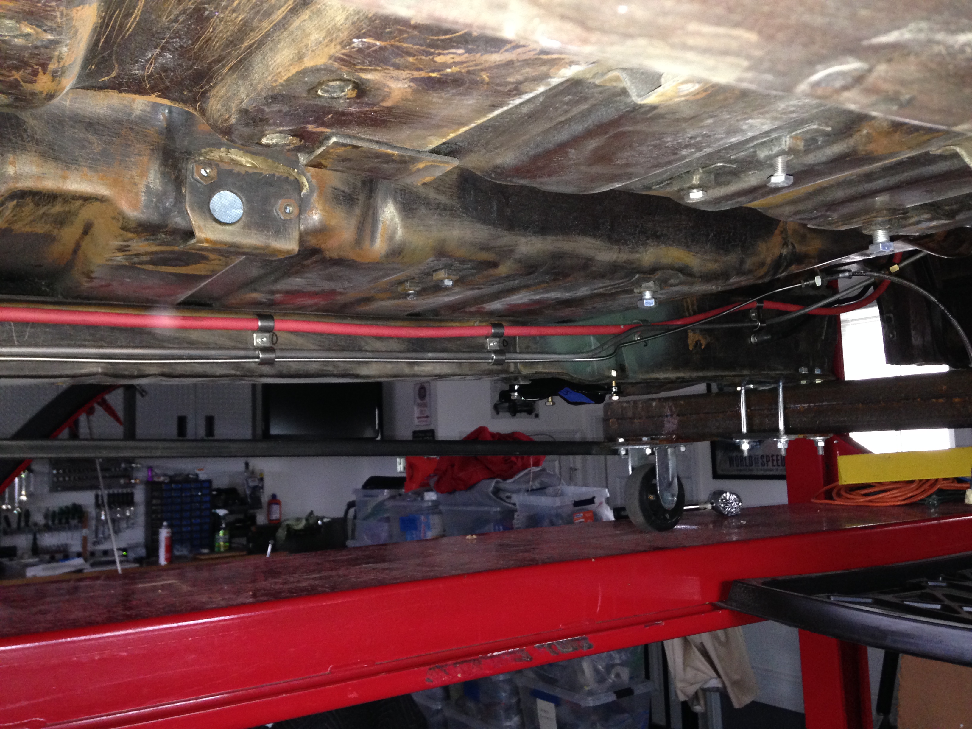
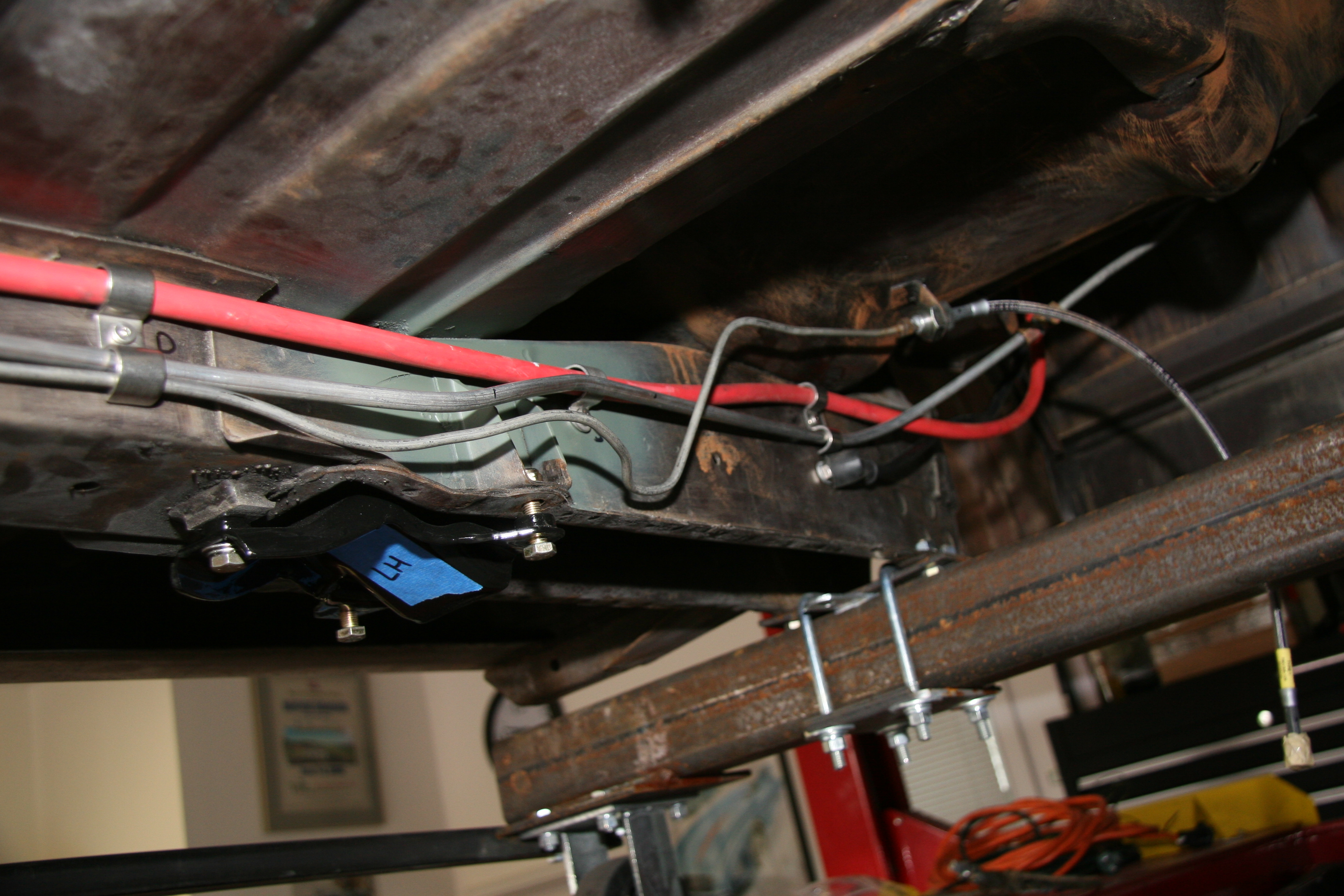
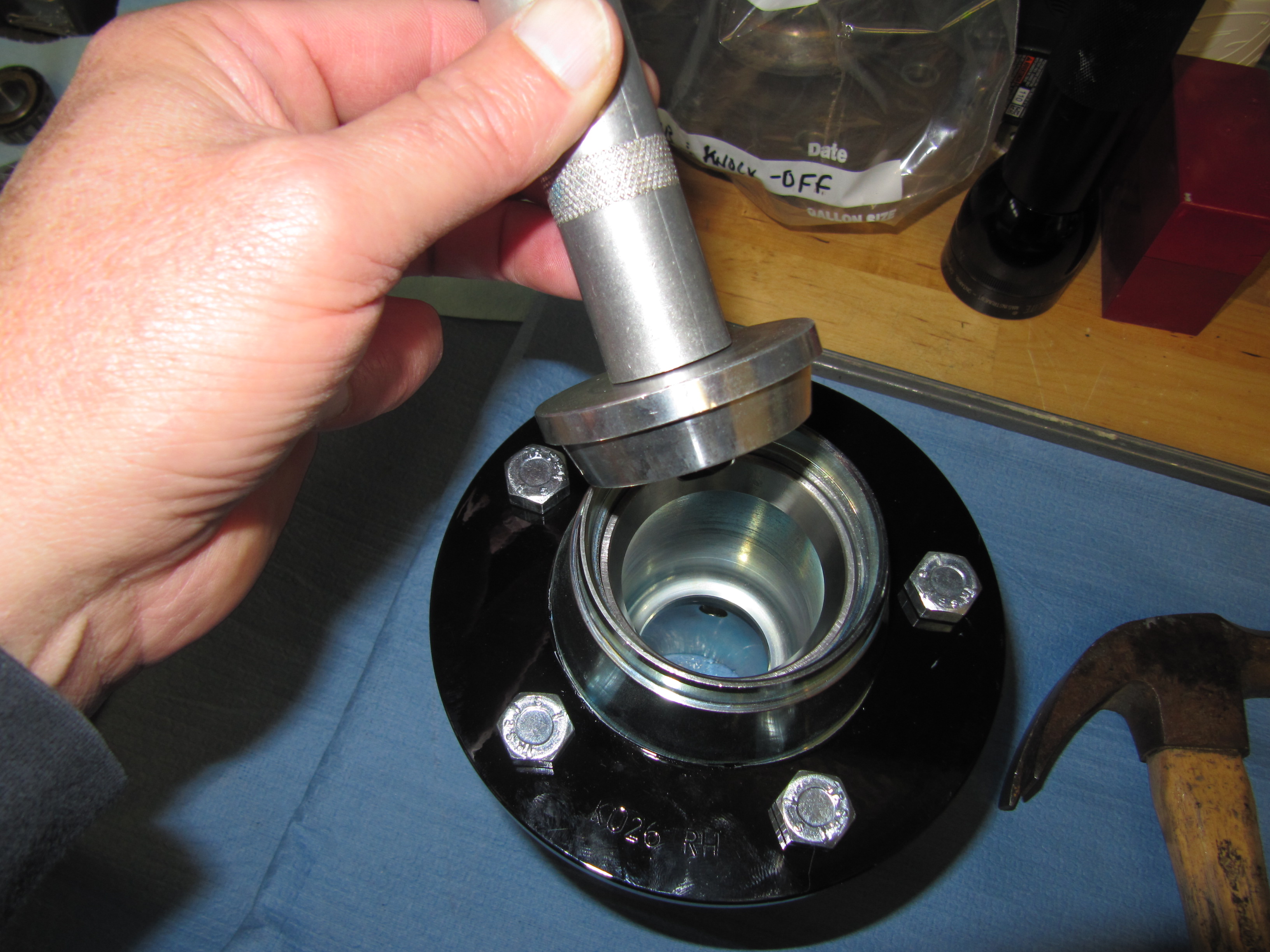
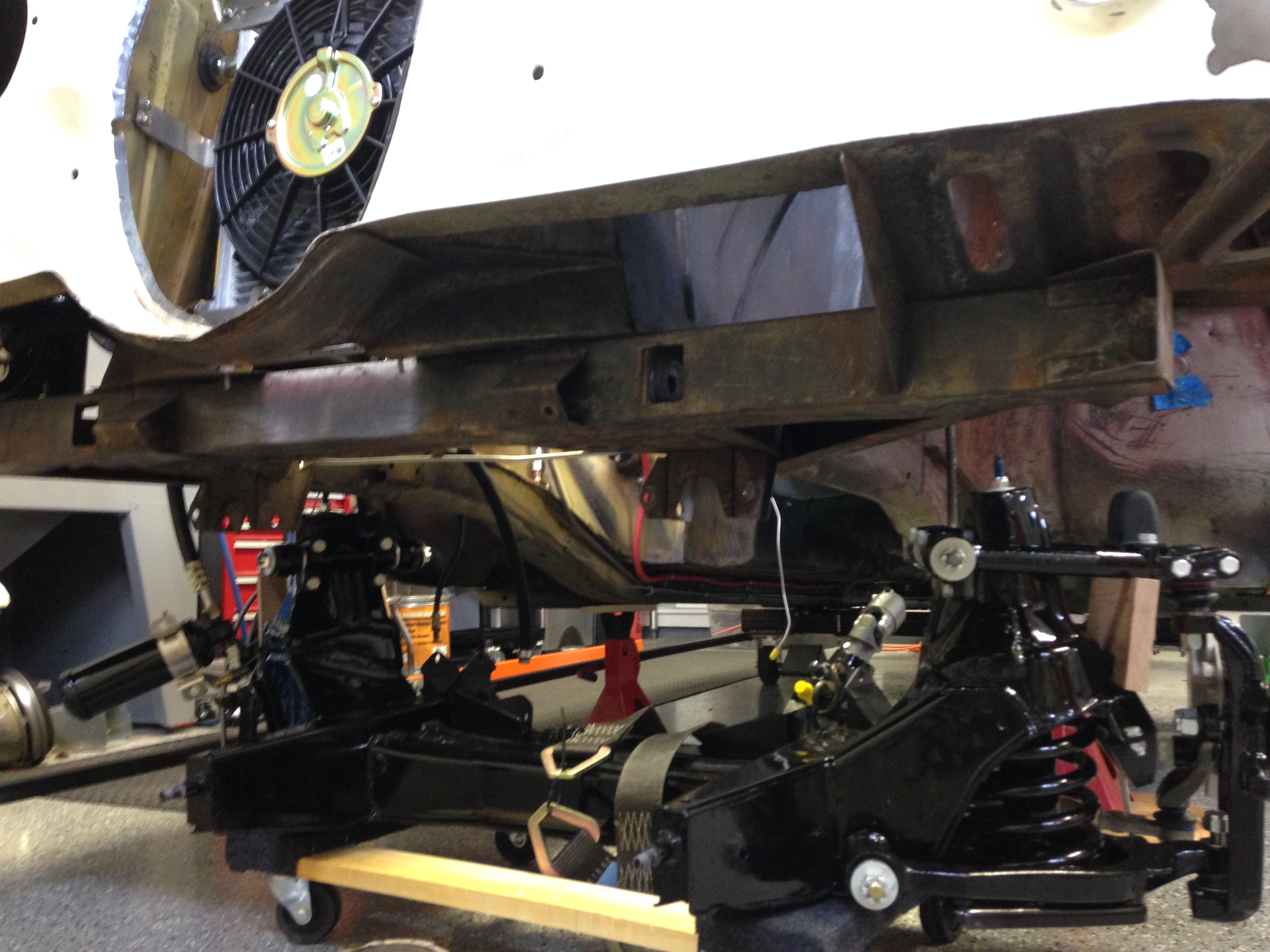
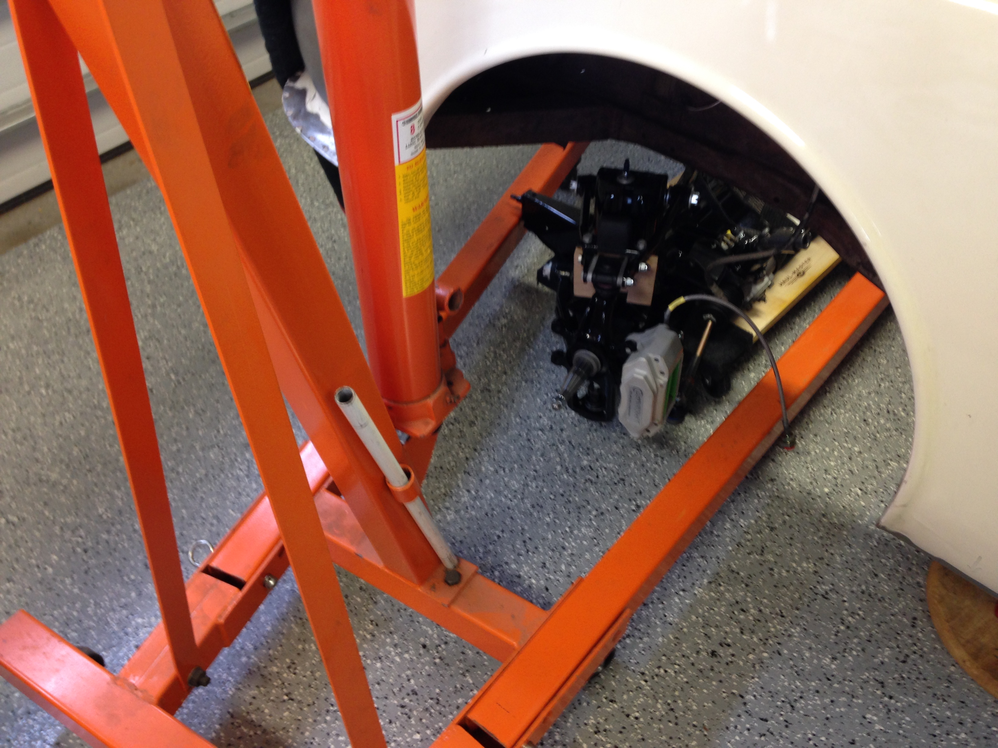
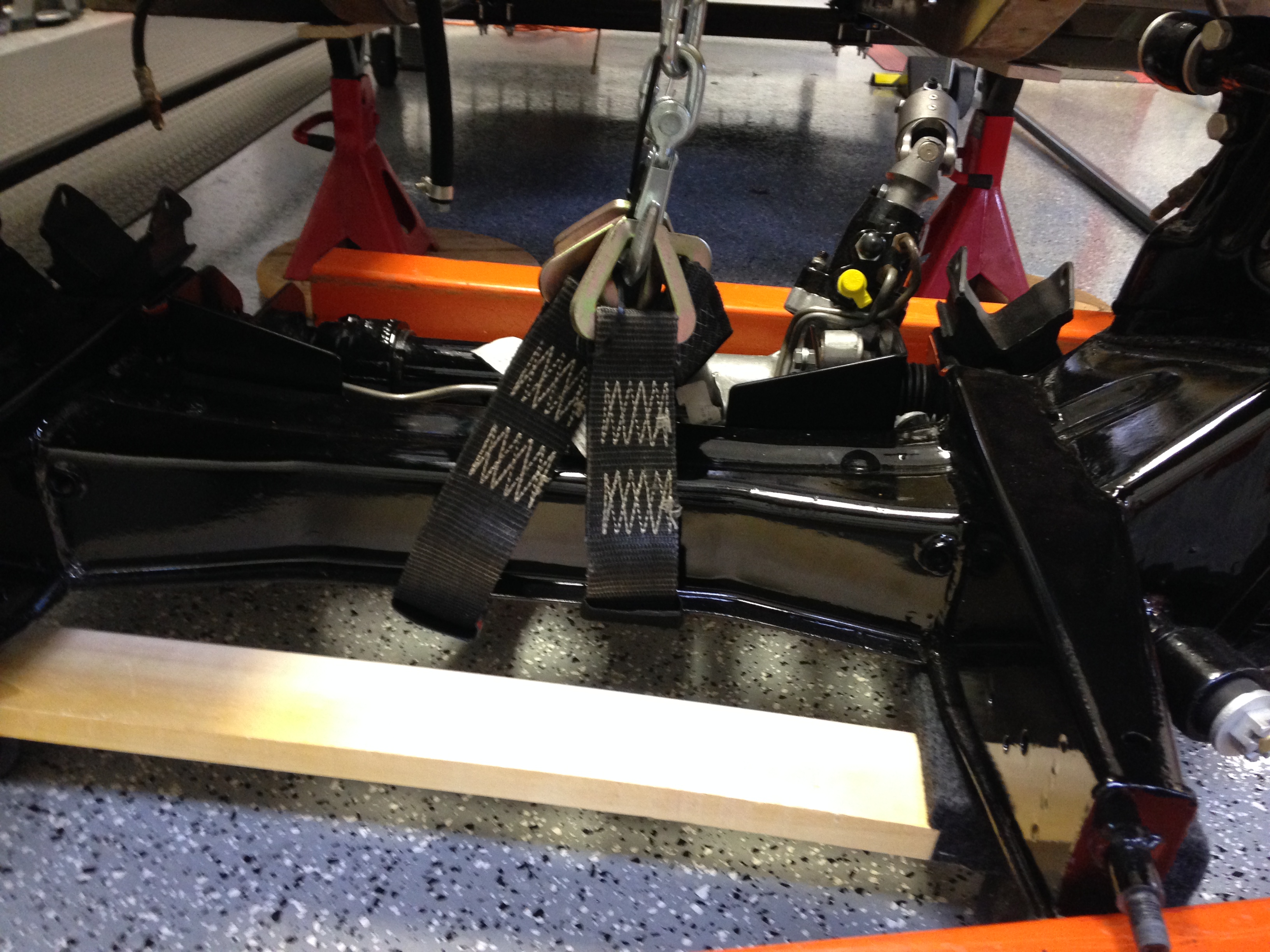
Battery Relocation to the Boot
The air conditioner evaporator must be mounted where the battery was originally, therefore the battery must be relocated to the boot. That process is described here: https://valvechatter.com/?p=6627
Mounting Brackets, Belts and Pulleys
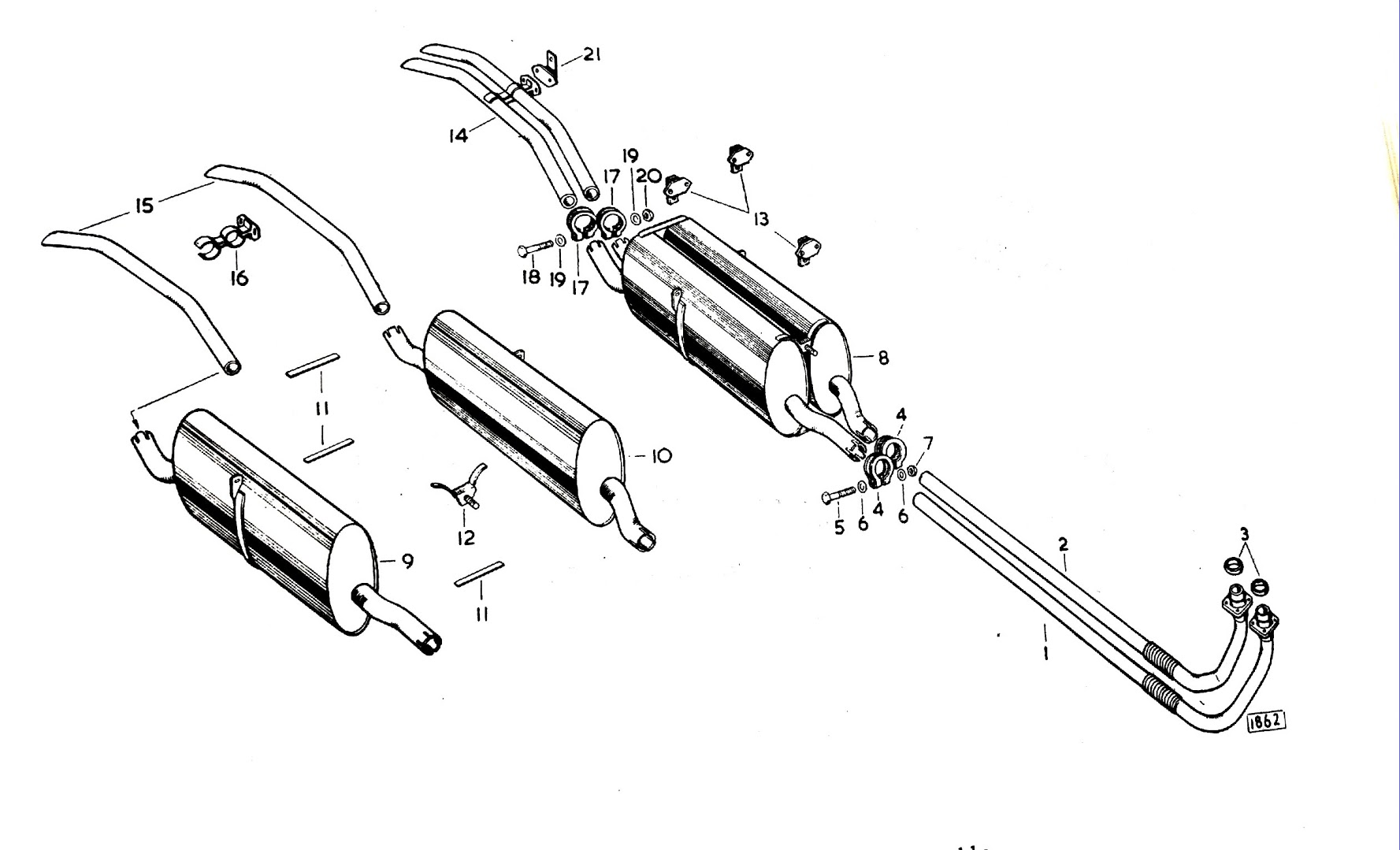
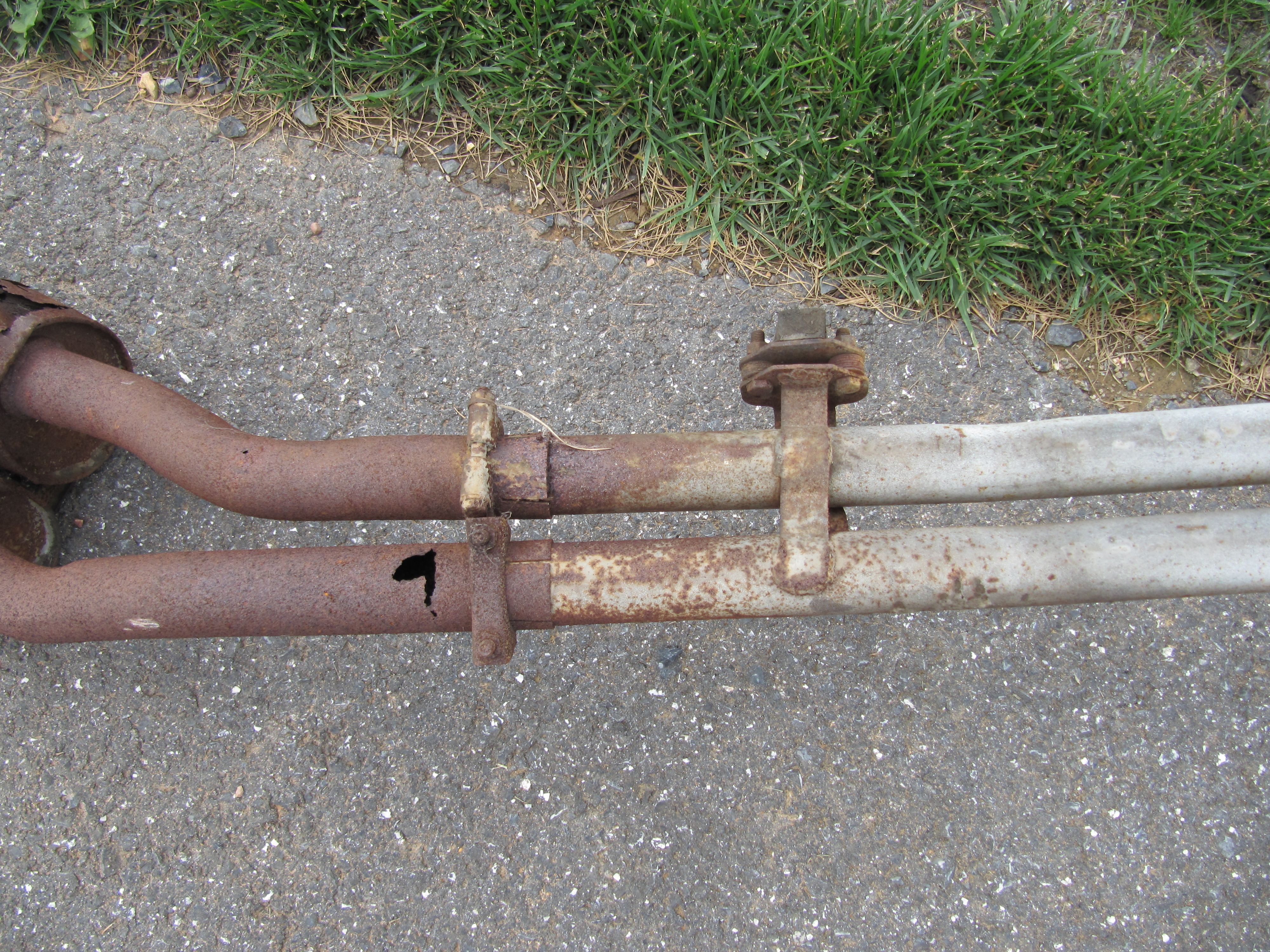
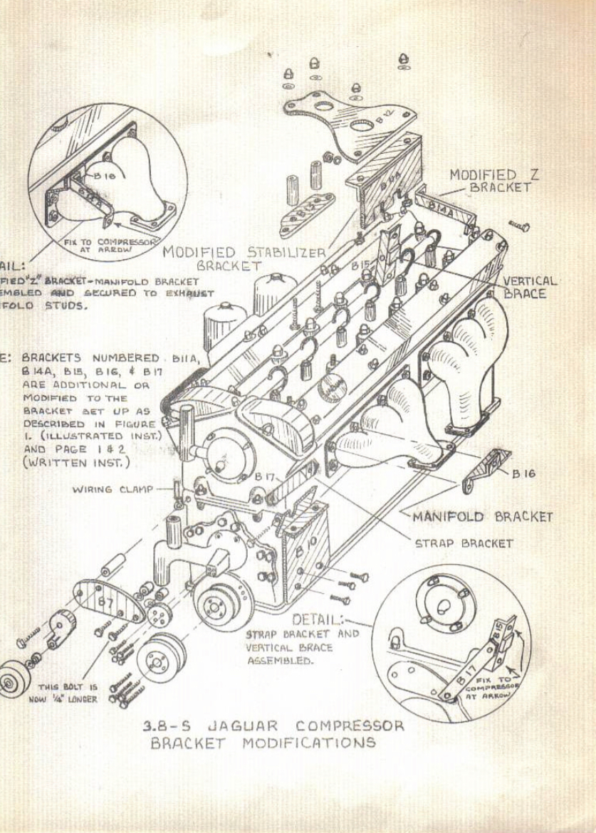
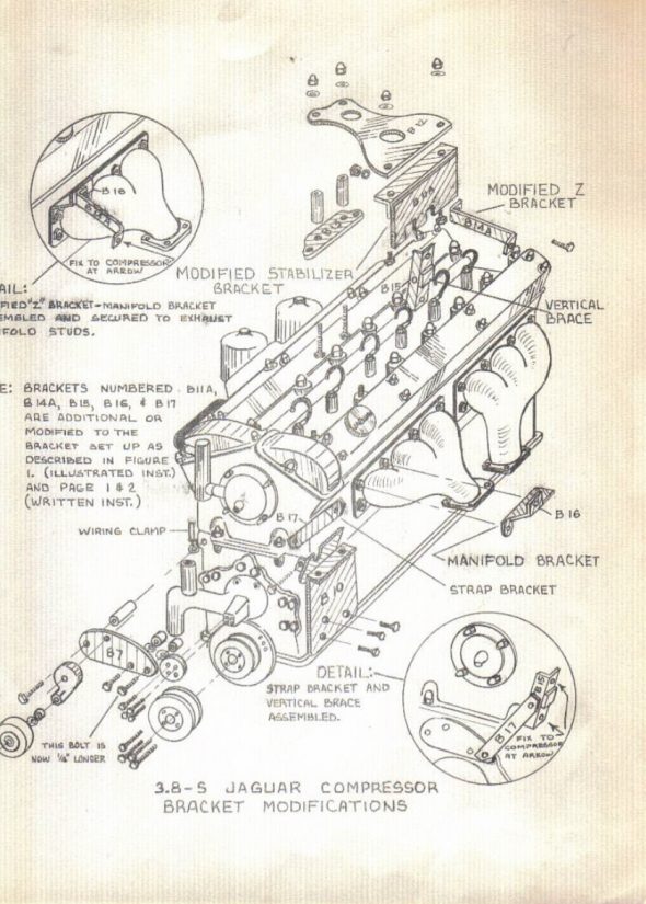
The illustration below is from The Guide and shows the bracket and pulley modifications for a dealer installed air conditioning system. A “V” belt crankshaft pulley was added in front of the original “W” or double “V” crank pulley. With this design, one “V” belt is used on the “outside” sheave to drive the compressor, tensioner and crankshaft pulley. While the original “W” or double “V” belt is used to drive the “inside” crankshaft pulley, the generator pulley, and the water pump pulley.
In this system, brackets to support the rather large York compressor are seen above the cylinder head, attached to the exhaust manifold, and a quite large heavy duty steel plate/bracket is used to secure the compressor to the three threaded bungs cast in the side of the engine block. One should also note the use of a tensioner pulley with eccentric arm and bracket located at the front of the engine and above the water pump. This pulley is used to tension the belt (and distance it so as to not conflict with the water pump pulley) used for the crankshaft and compressor pulleys.
Jaguar MK2 Air Conditioing Brackets
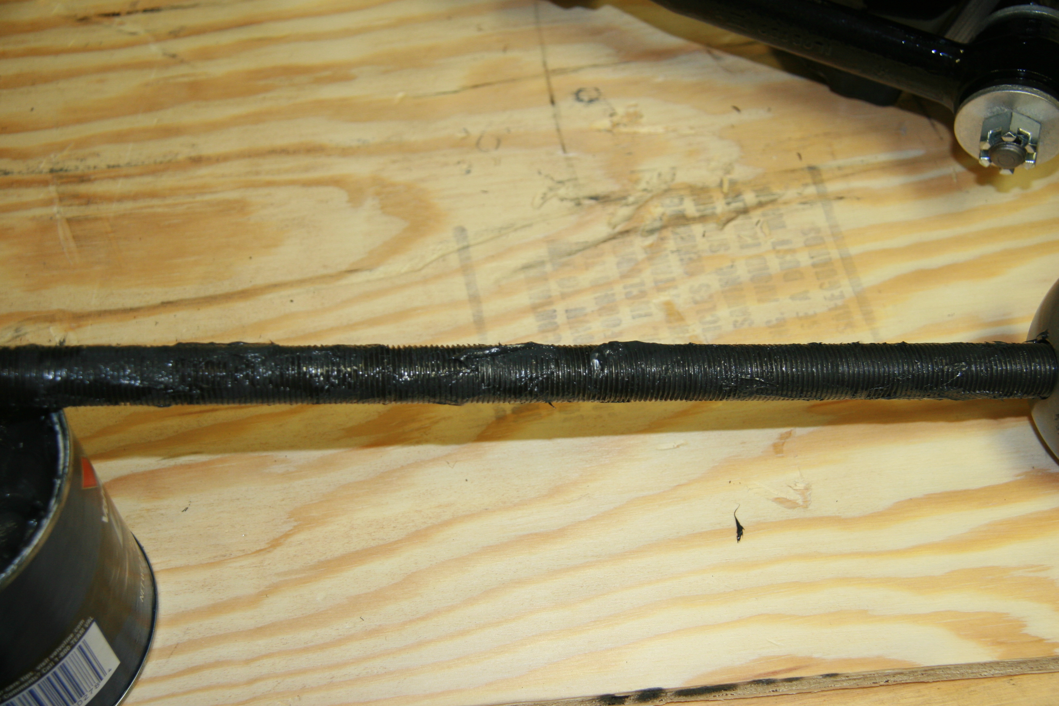
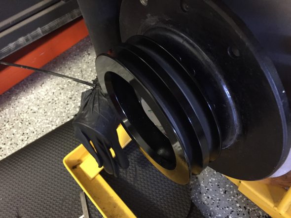
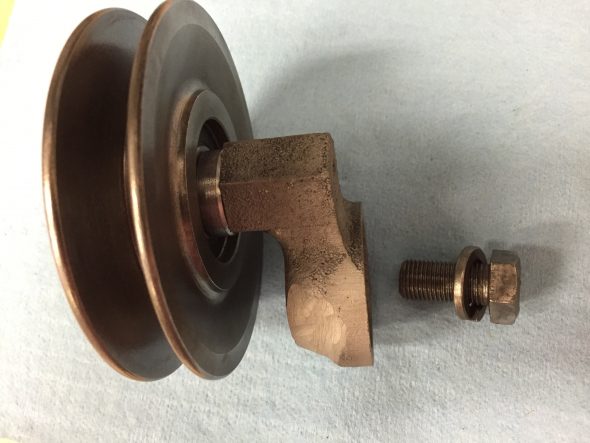
Apparently (this is my own assessment and is not supported by any definitive research of which I am aware), somewhere along the line – perhaps with the MK IX? a single twin groove “V” belt pulley was adopted. This is a chipped example:
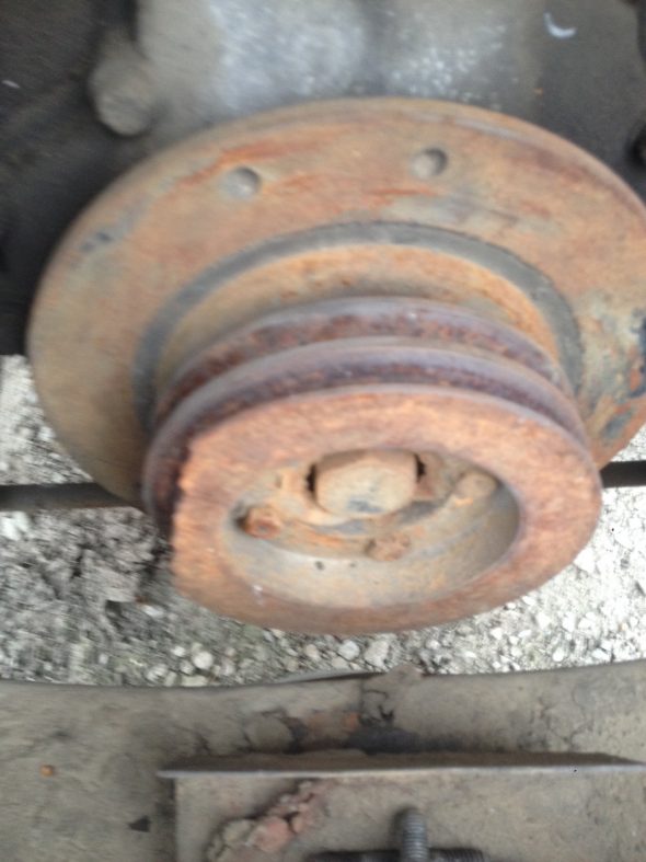
Chipped Twin Groove “V” belt pulley – MK IX
I purchased the aluminum alloy driveshaft pulley and water pump pulley from RetroAir as well as an idler pulley. Additionally, and as part of the kit, I purchased the RetroAir compressor bracket. As pointed out at the beginning of this post, The RetroAir approach has all pulleys on one “V” belt. However, in my application I have decided to use a two belt system using “V” pulleys and I have located (with Robert Seligman’s help!) original brackets as depicted in the Jaguar diagram above.
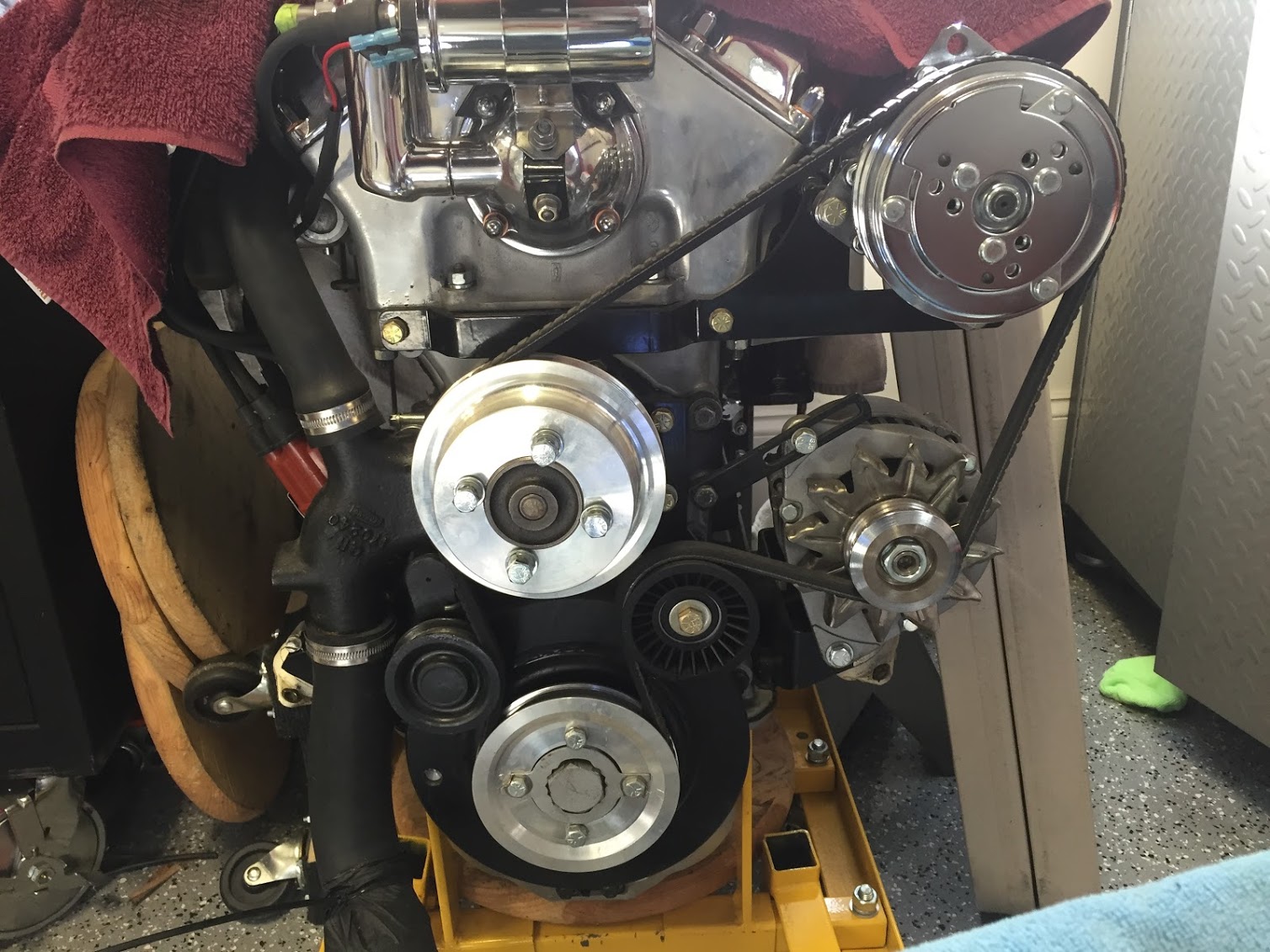
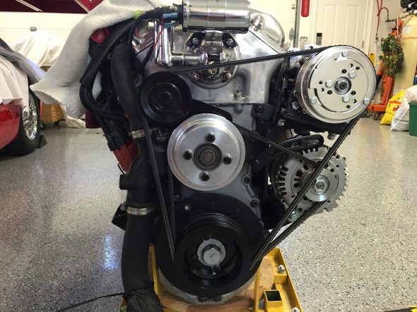
The RetroAir compressor bracket and pulleys may be seen in the image of my engine below:

Rose Engine Pulleys – Early Iteration
In the image above, the belt is on the wrong side of the jockey pulley and it shows an alternator that is not the Hitachi that I am actually using. The photo is provided solely to show the two aluminum pulleys, the idler pulley, the compressor and the compressor bracket purchased as part of the RetroAir kit. The compressor bracket also has a rear mount and both are supplied in a grey color. I powder coated both black.
The Big Switch
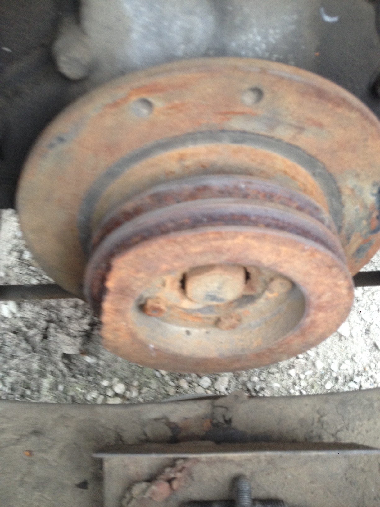
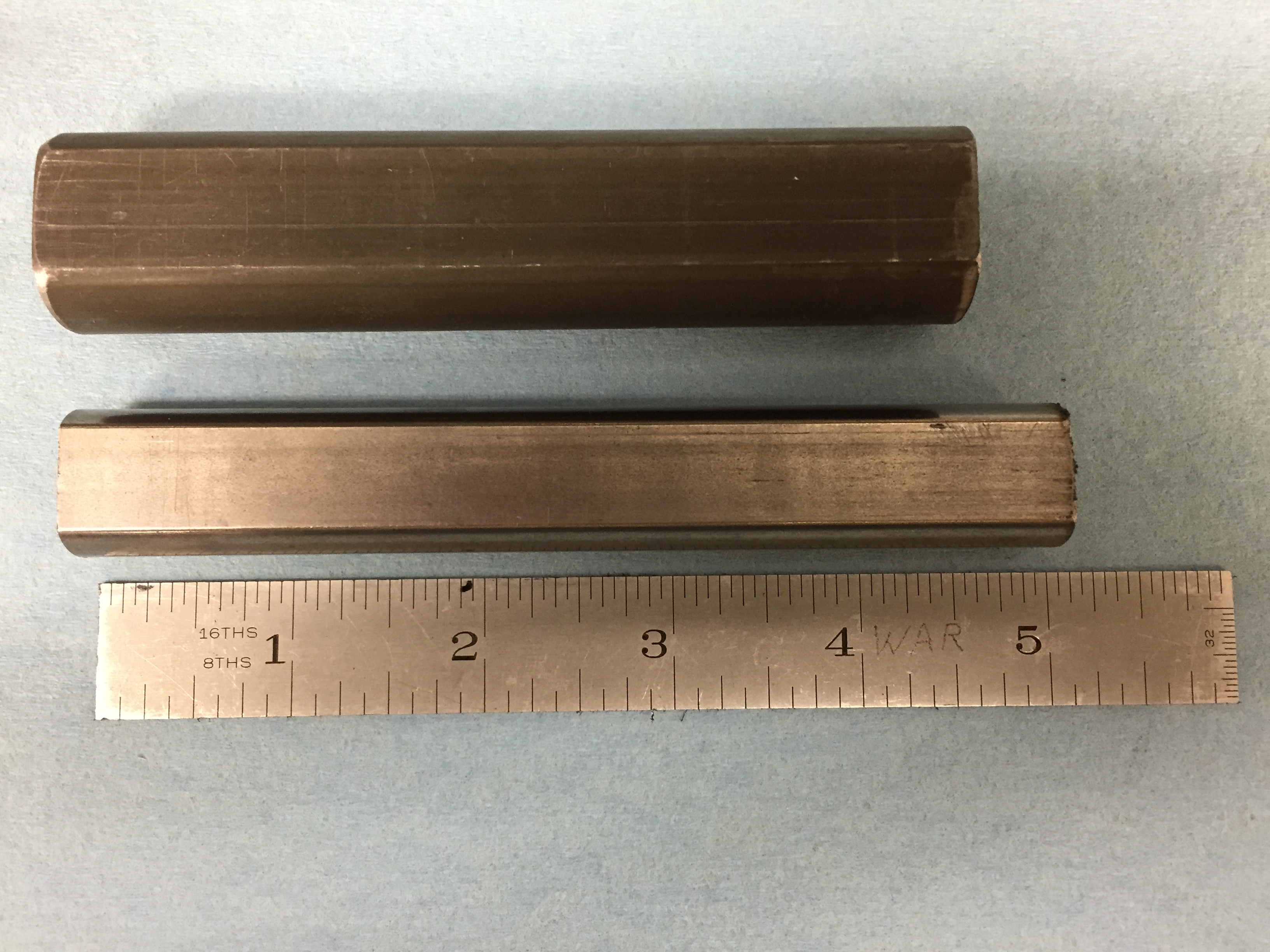
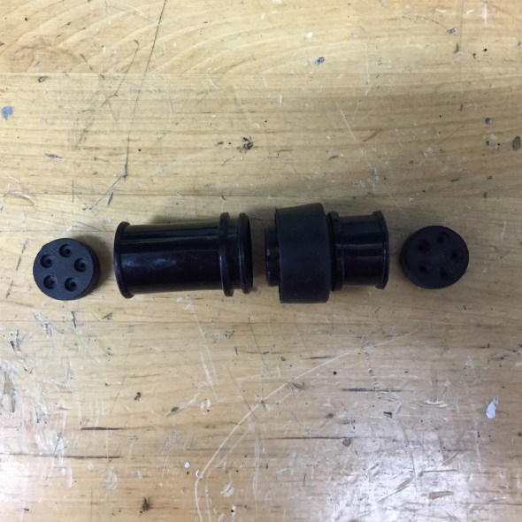
The heart of the pulley/belt system is the crankshaft pulley that drives both belt circuits. I searched and searched for the proper twin groove pulley, if there is such thing, and never came up with it. However, on eBay, I did find a 1990 Jaguar XJS three groove “V” crank pulley. I machined away the outside groove of the pulley and ended up with a crank pulley that I believe will serve my needs.
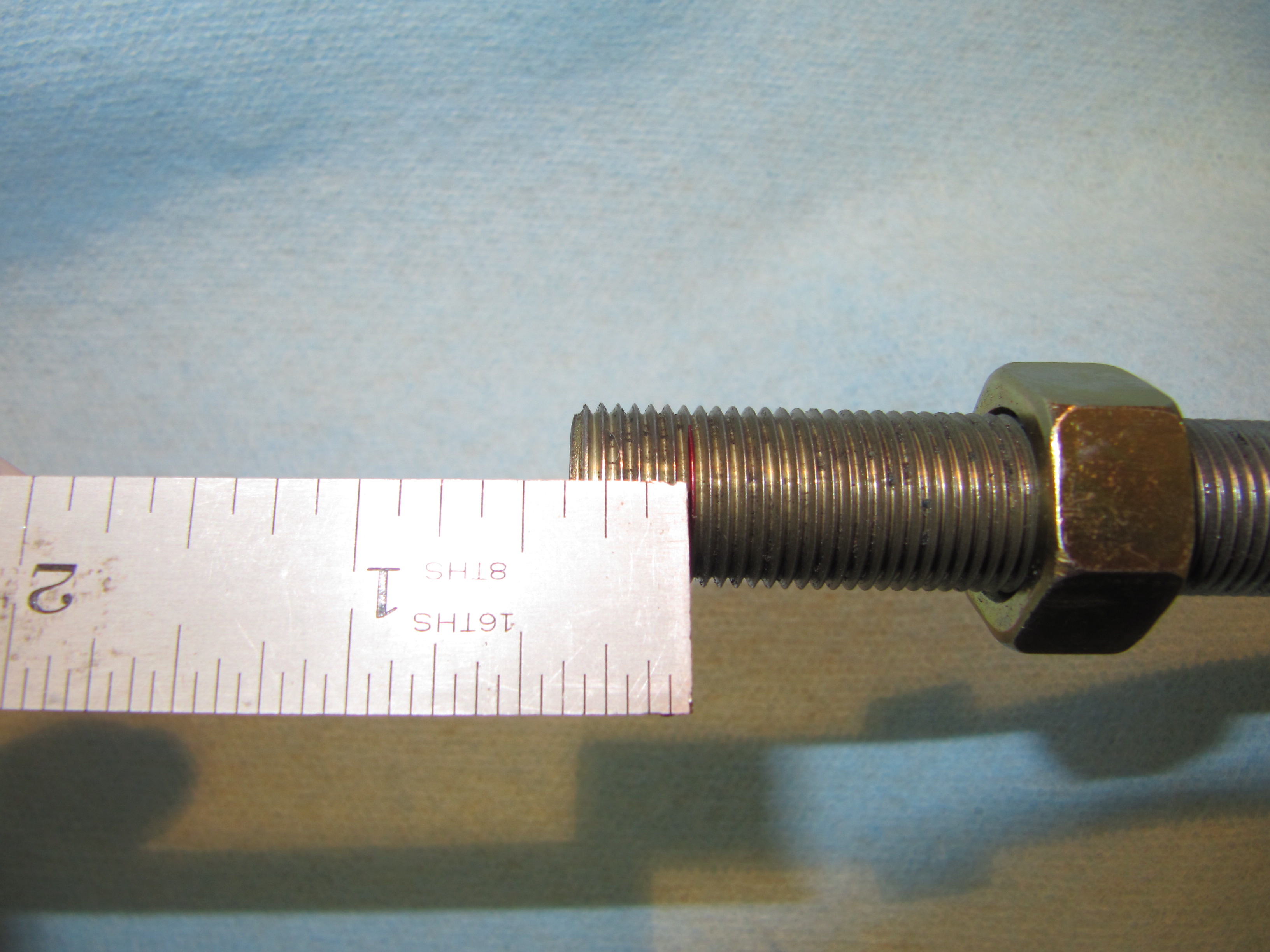
1990 XJS Crank Pulley as Purchased

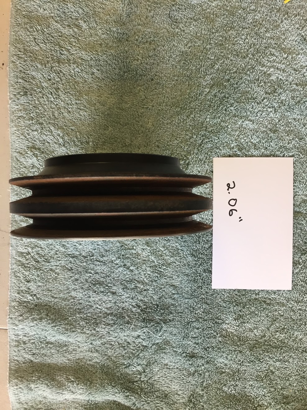
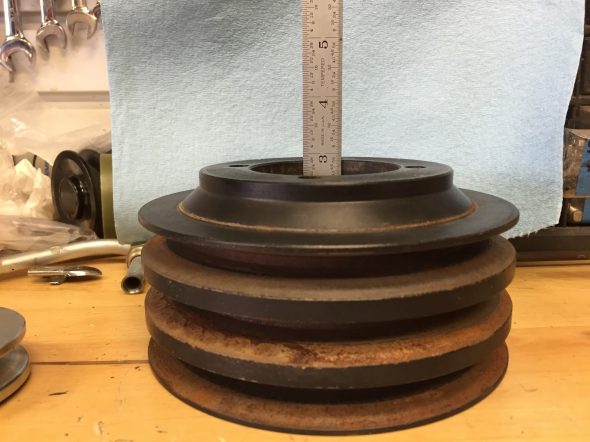
1990 XJS Crank Pulley 2.06″ Deep After Machining
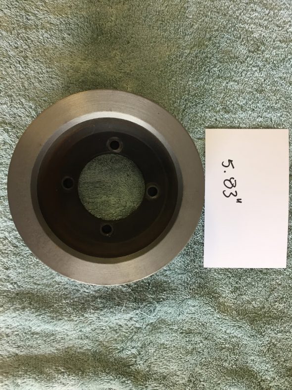
1990 XJS Crank Pulley 5.83″ Diameter
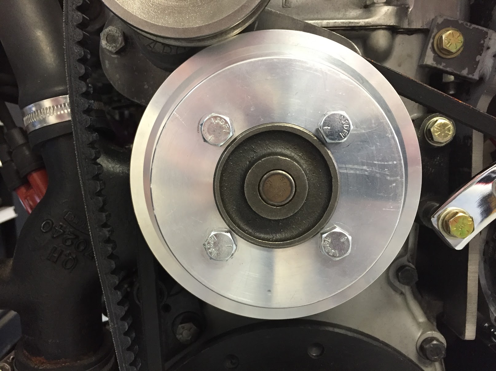
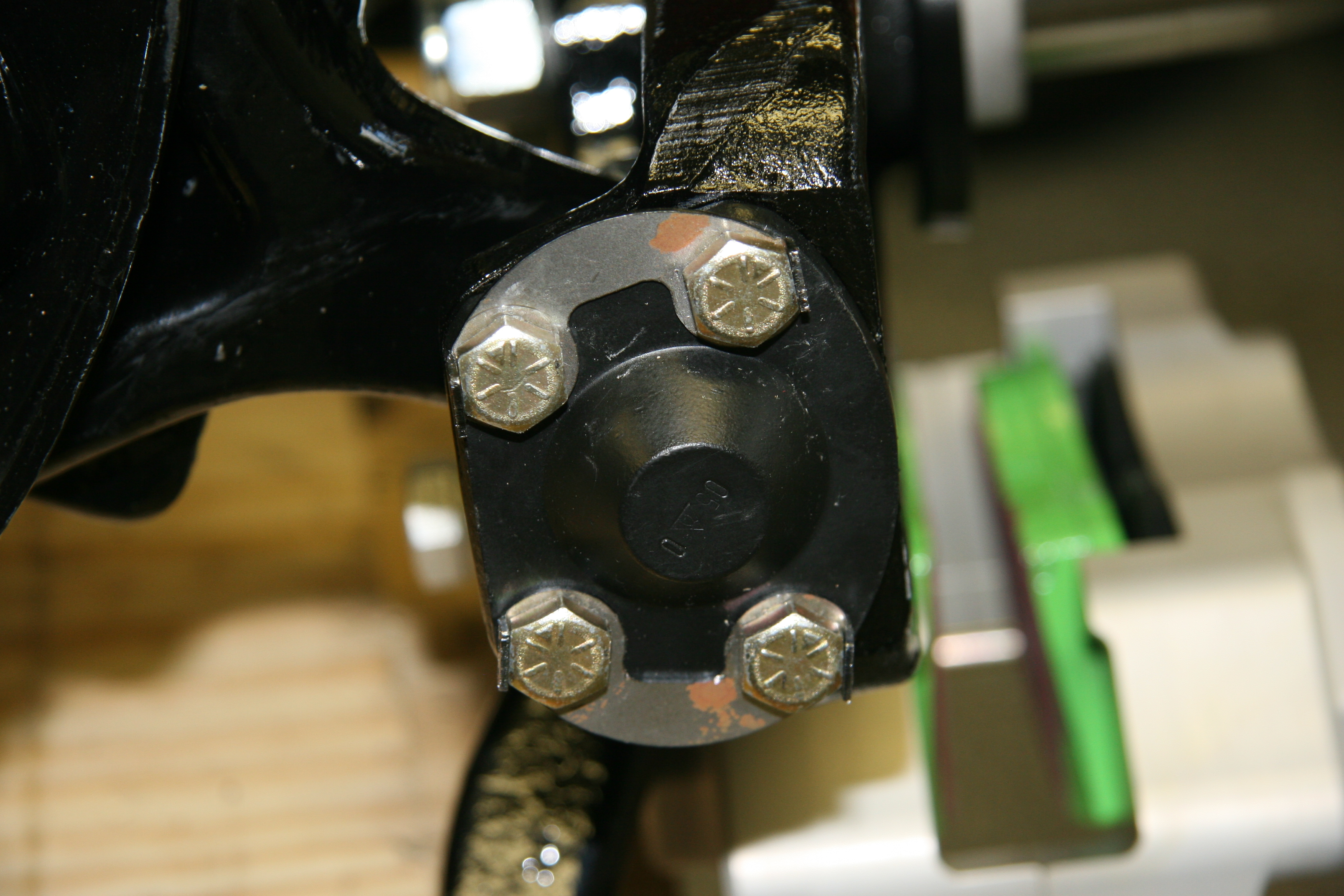
The XJS pulley is .65″ larger in diameter than my original MK2 pulley. At just slightly deeper than 2″, the modified XJS crank pulley will fit behind the fan without conflict. The pulley is mounted to the harmonic balancer with four 5/16″ – 24 x 1-1/4″ hex head bolts. Two bolts use split washers and the other two use a tab washer.
Two-Groove Painted Crank Pulley Installed
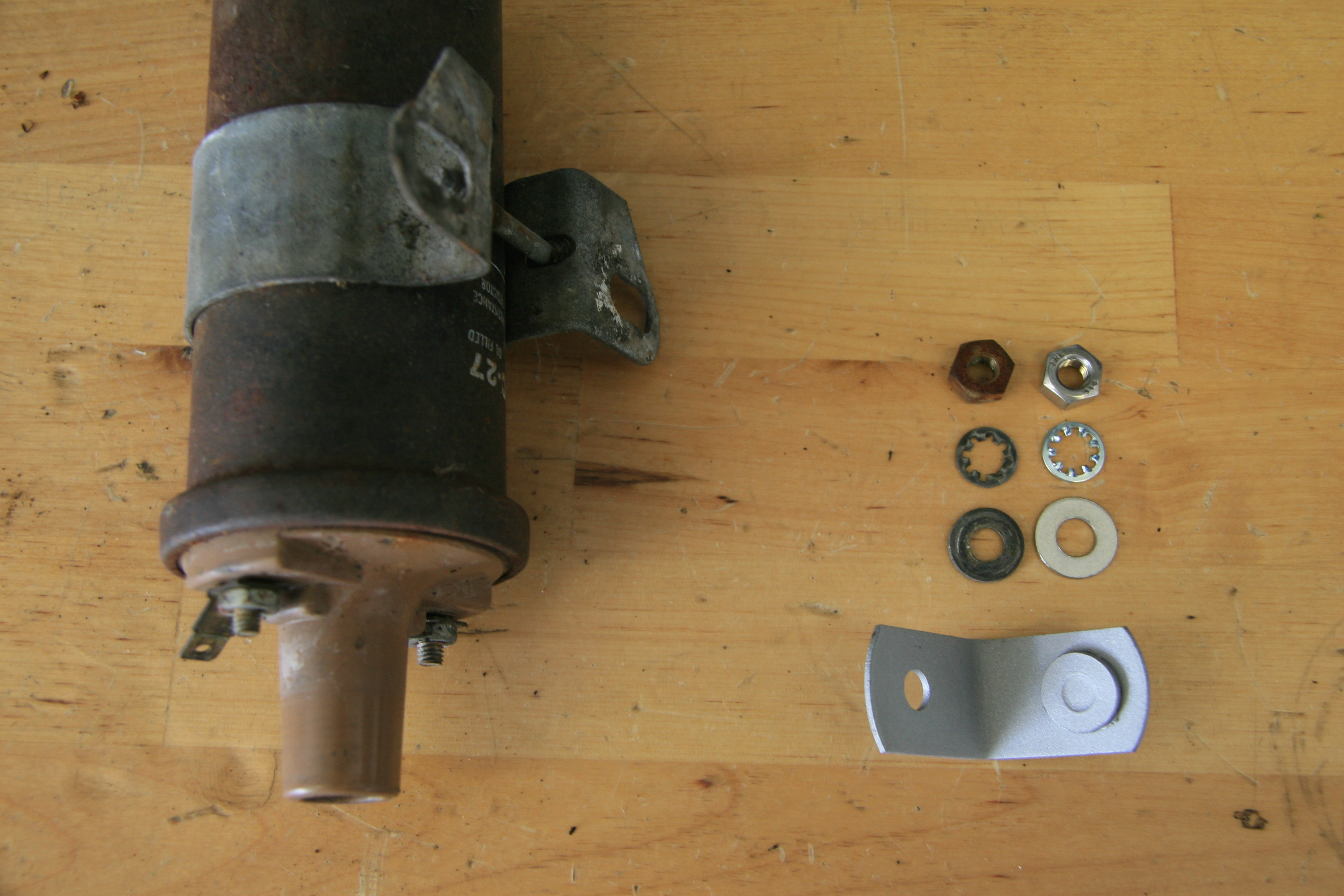
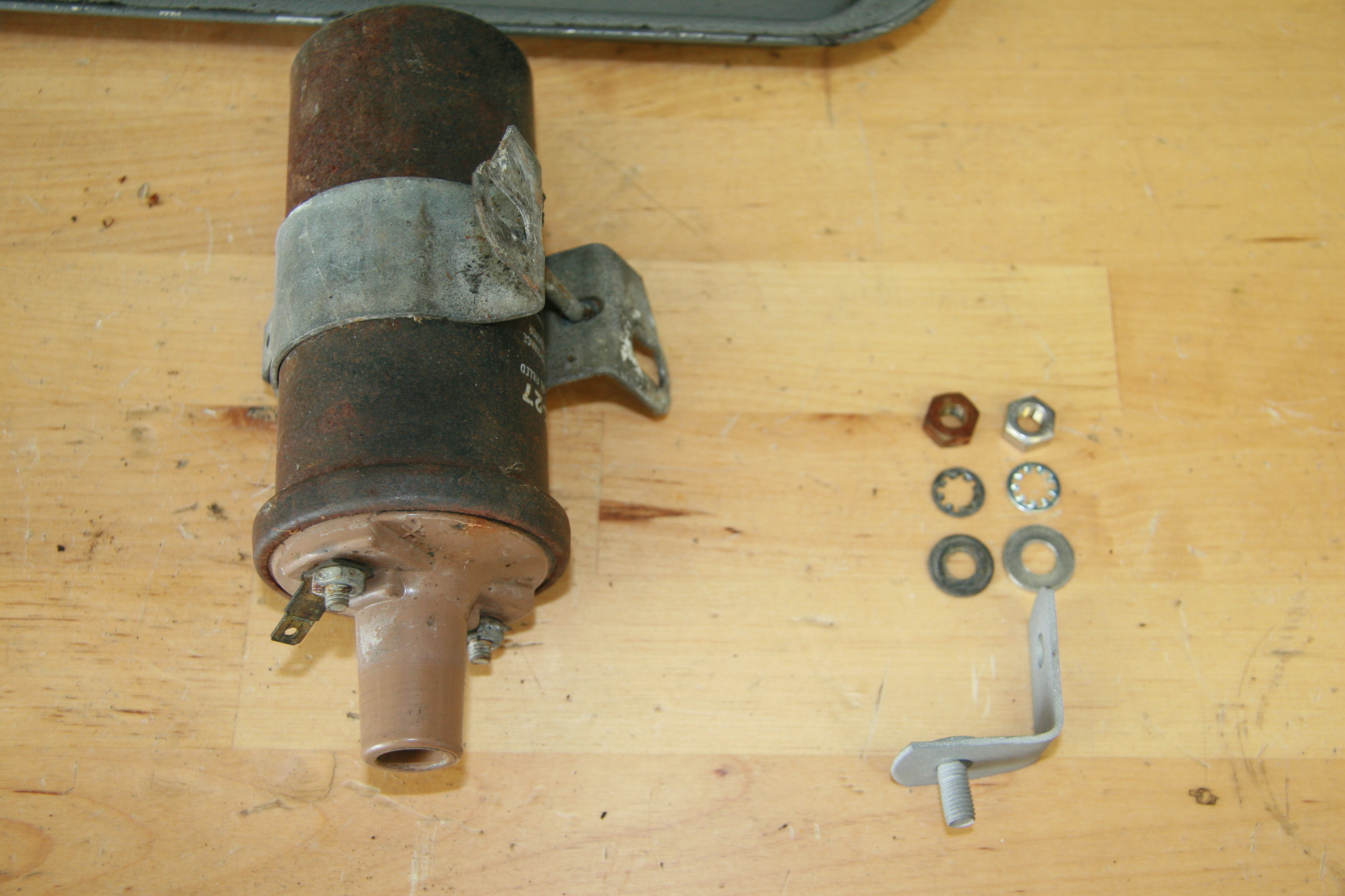
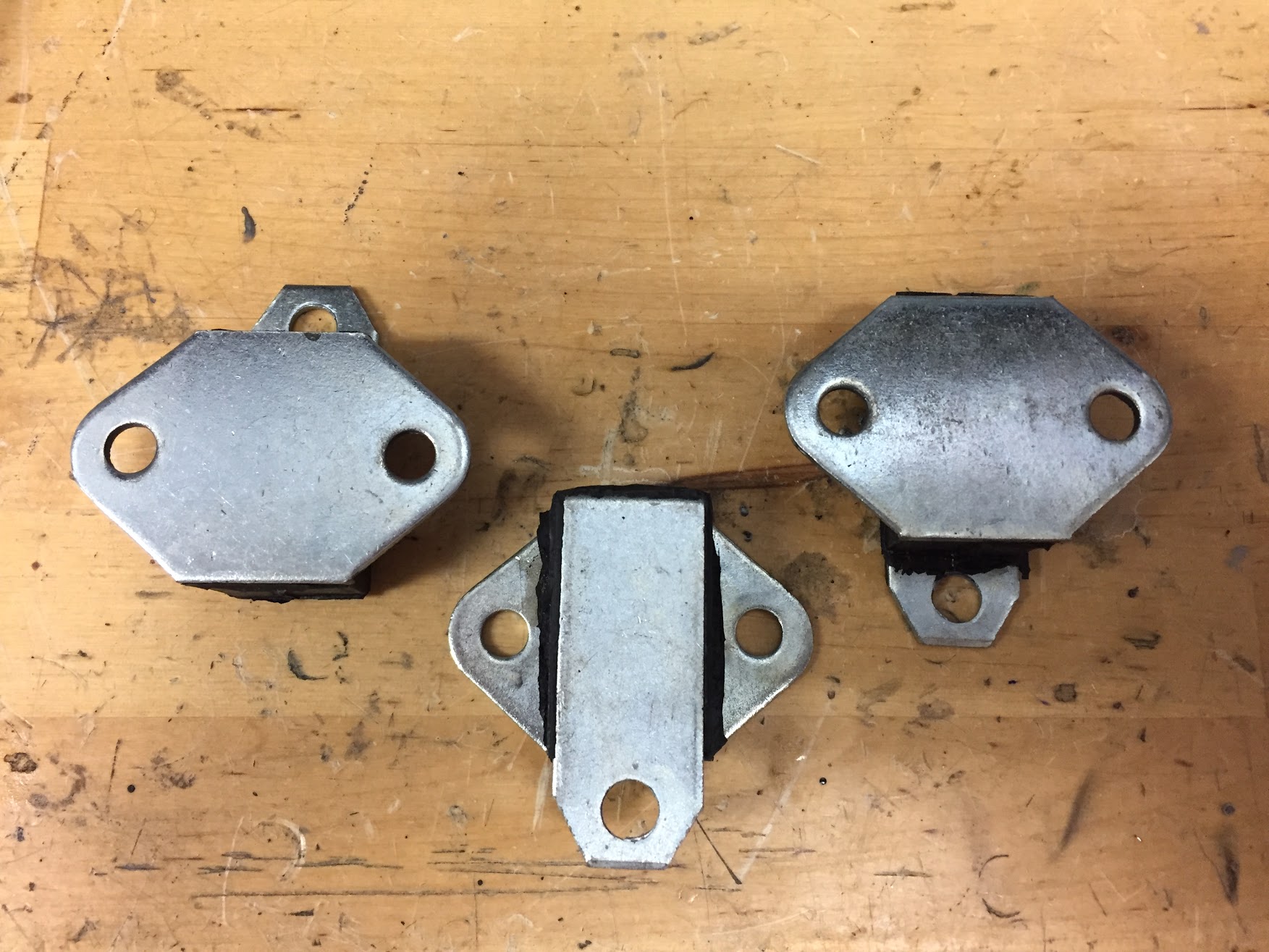
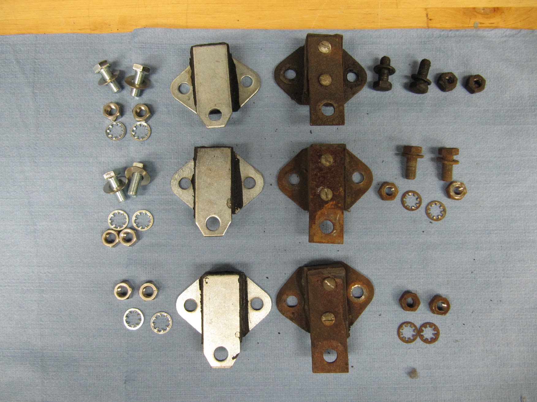
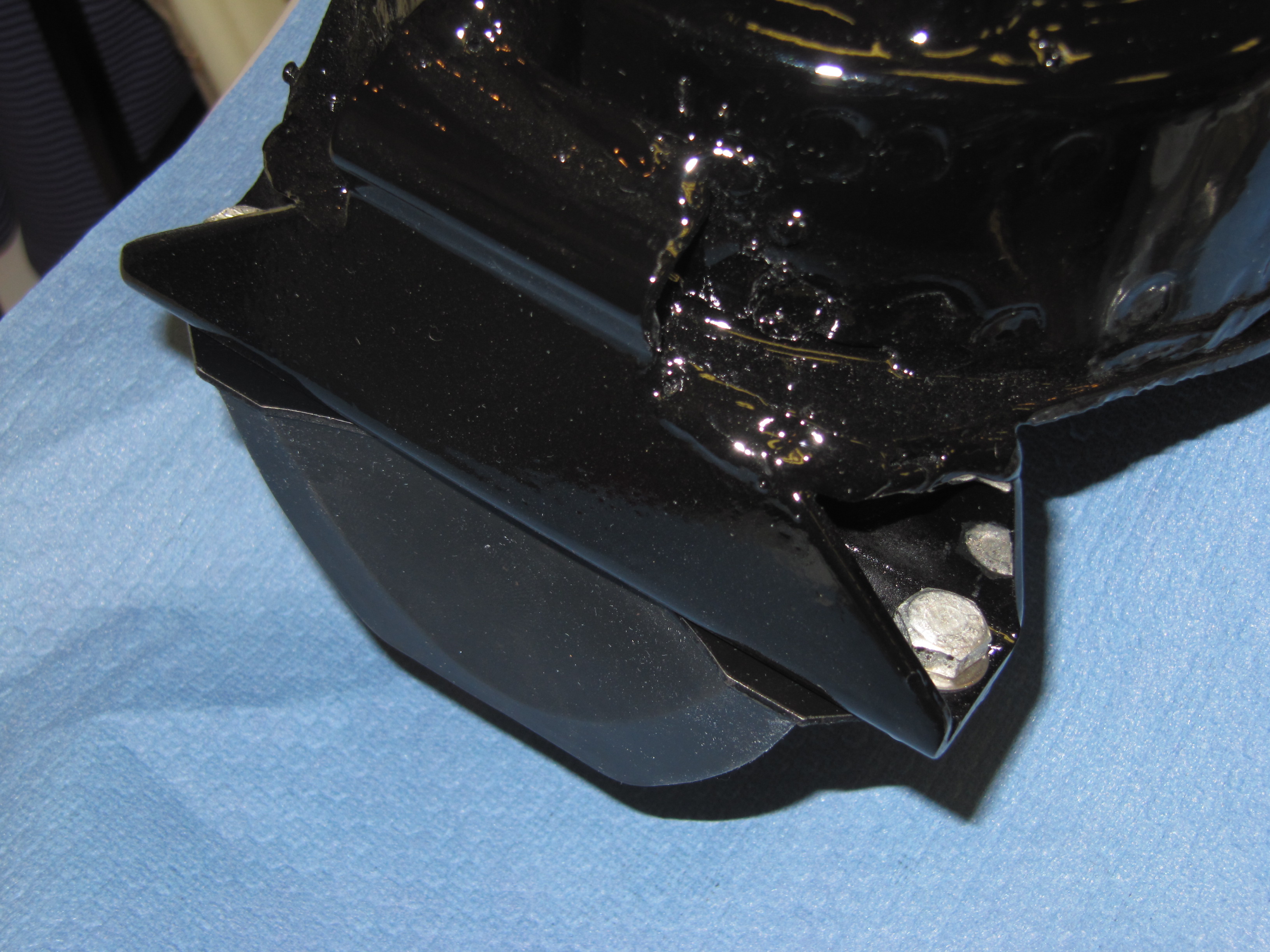
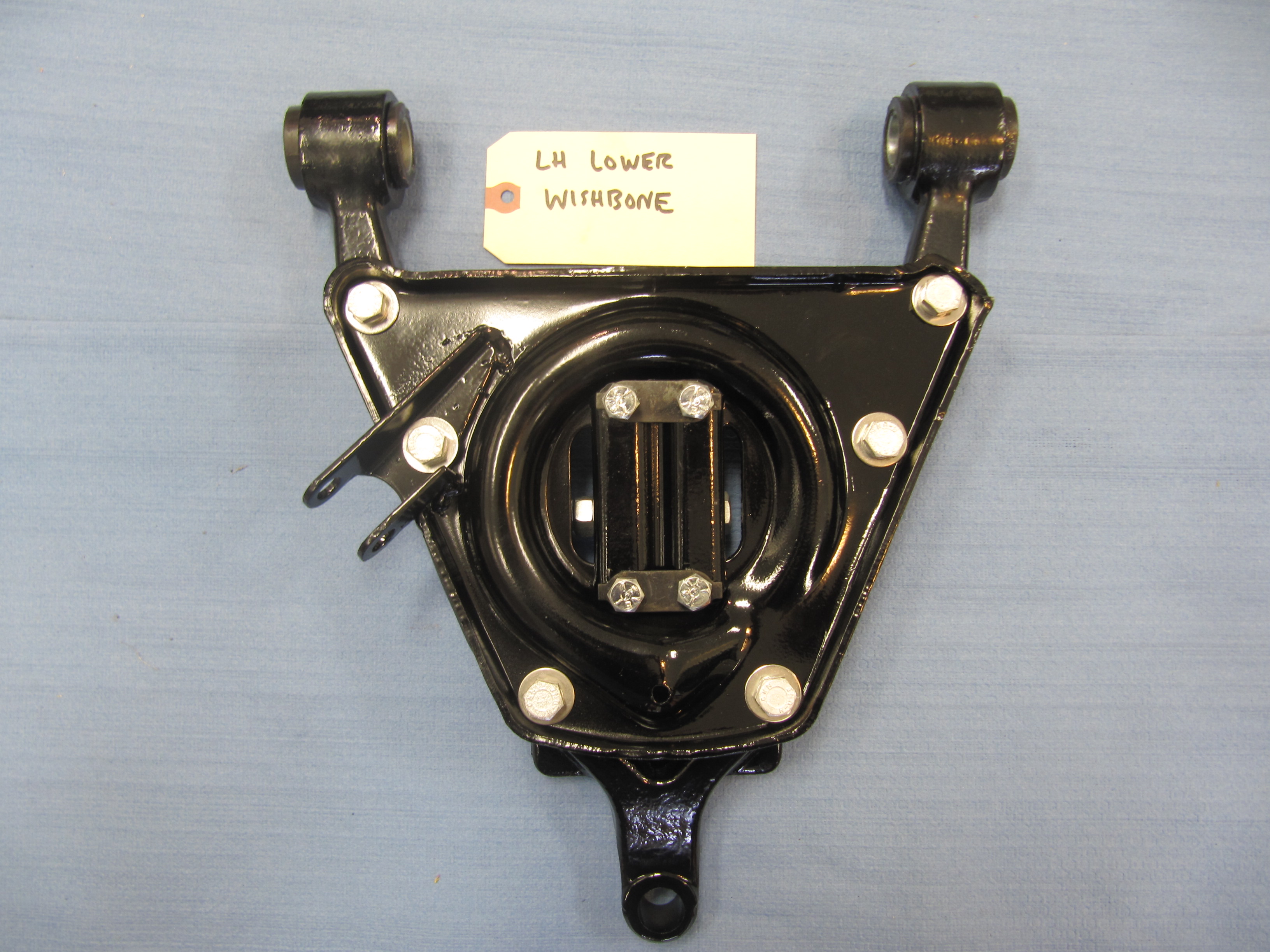
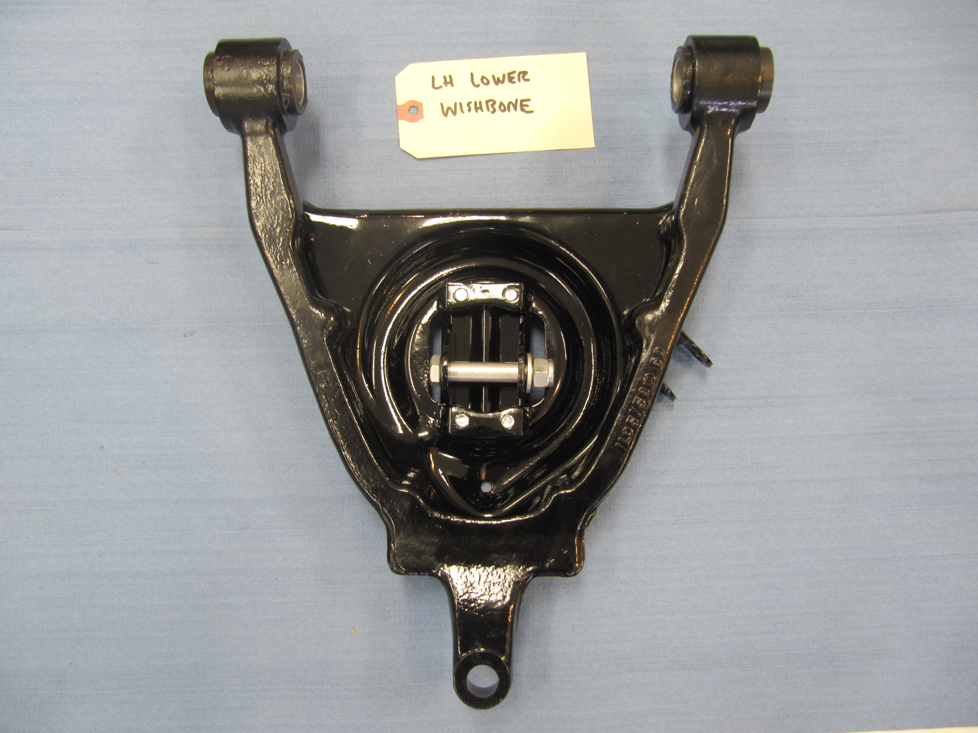
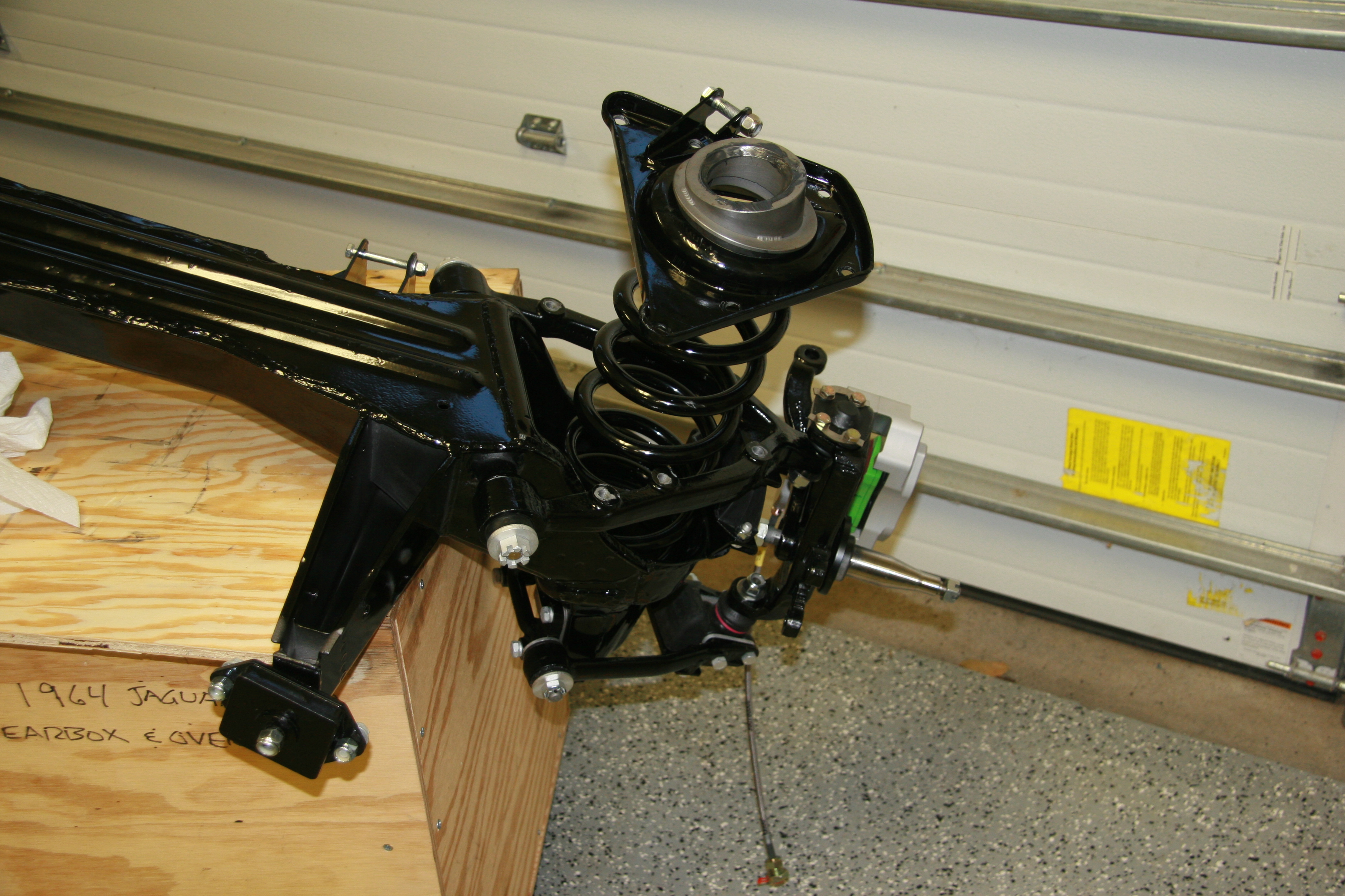
Having decided on my crankshaft pulley, I then began my search for other parts I needed. I sent emails to all of the Jaguar parts breakers I could think of trying to find original parts. I think it is fair to safe that these are pretty rare. Dan at Jaguar Heaven responded that he had the mounting brackets and parts for the addition of the compressor to a MK2. I ordered and waited hoping that what I purchased was what I really needed. Dan delivered and the parts are shown below after cleaning.
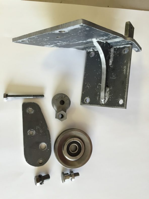
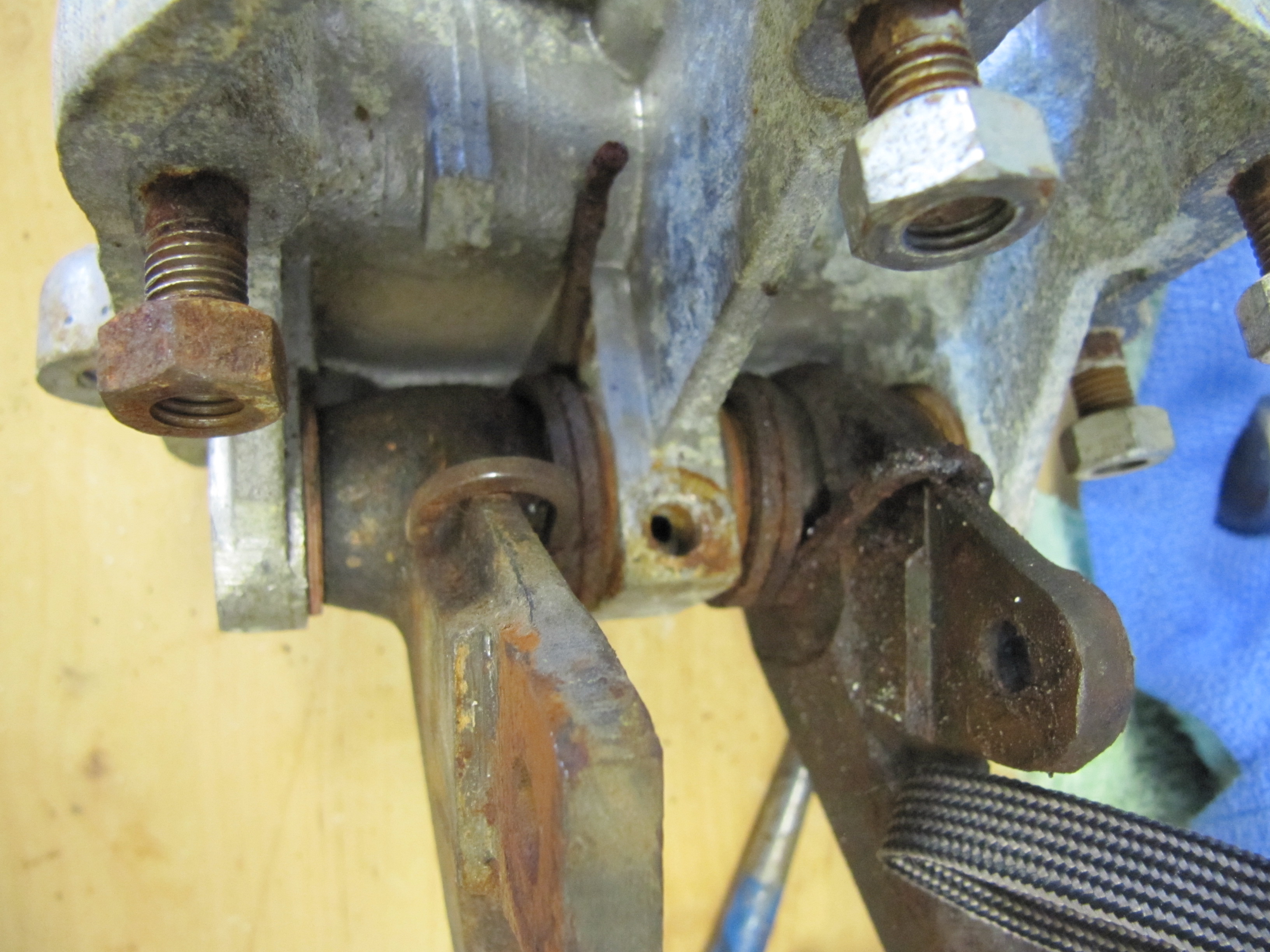
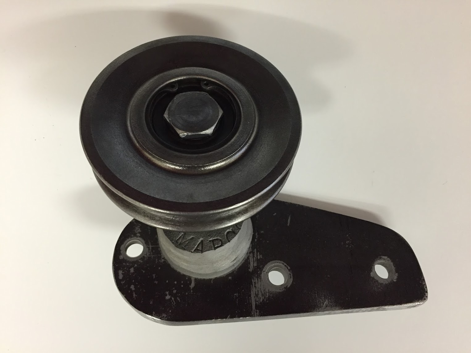
Air Conditioning Brackets and Tensioner Pulley
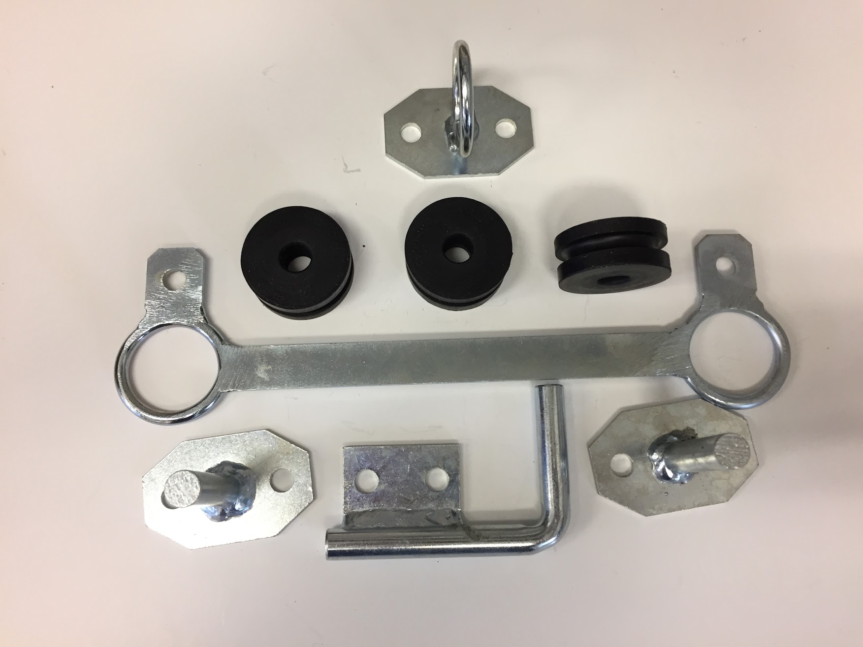
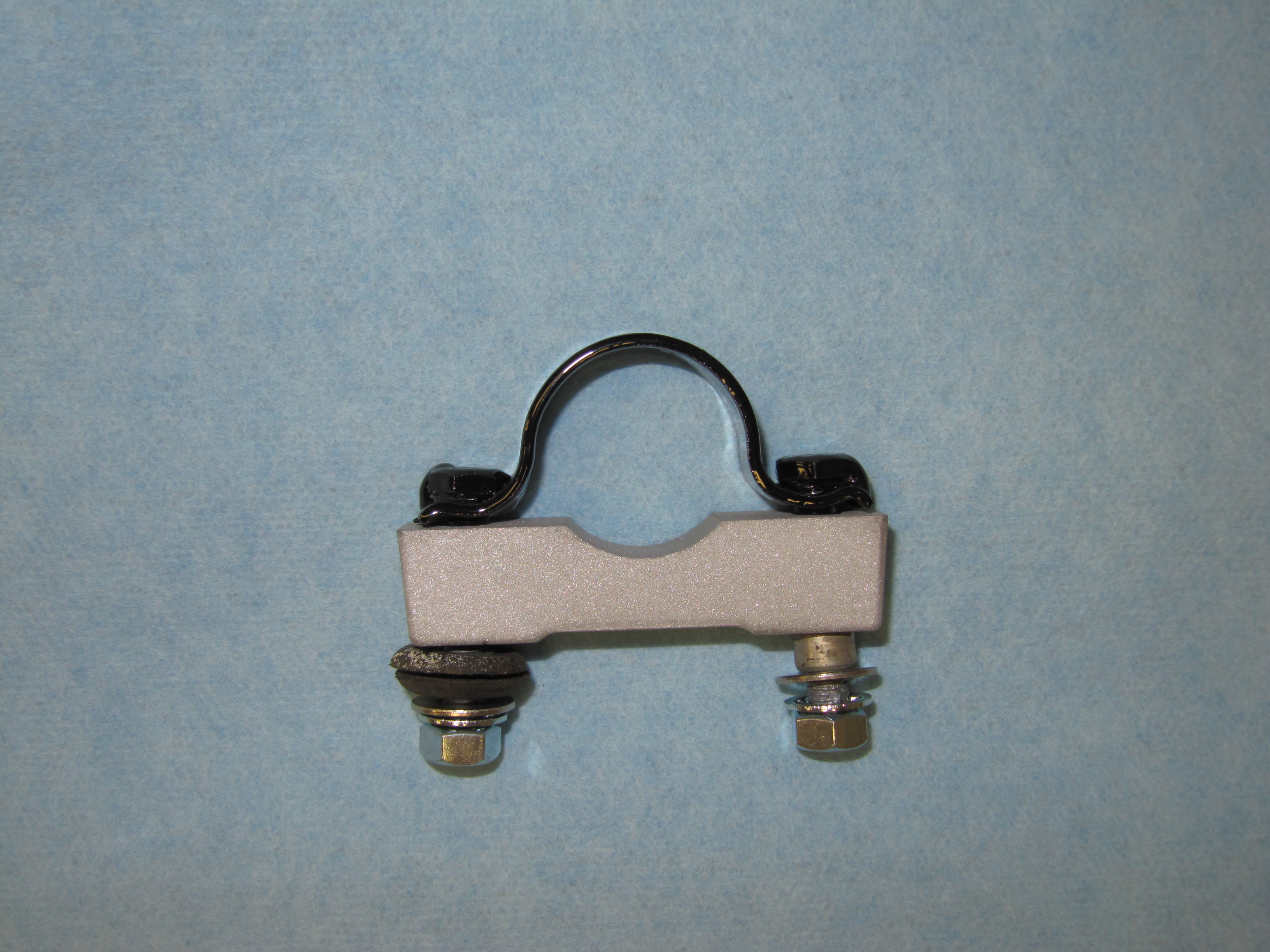
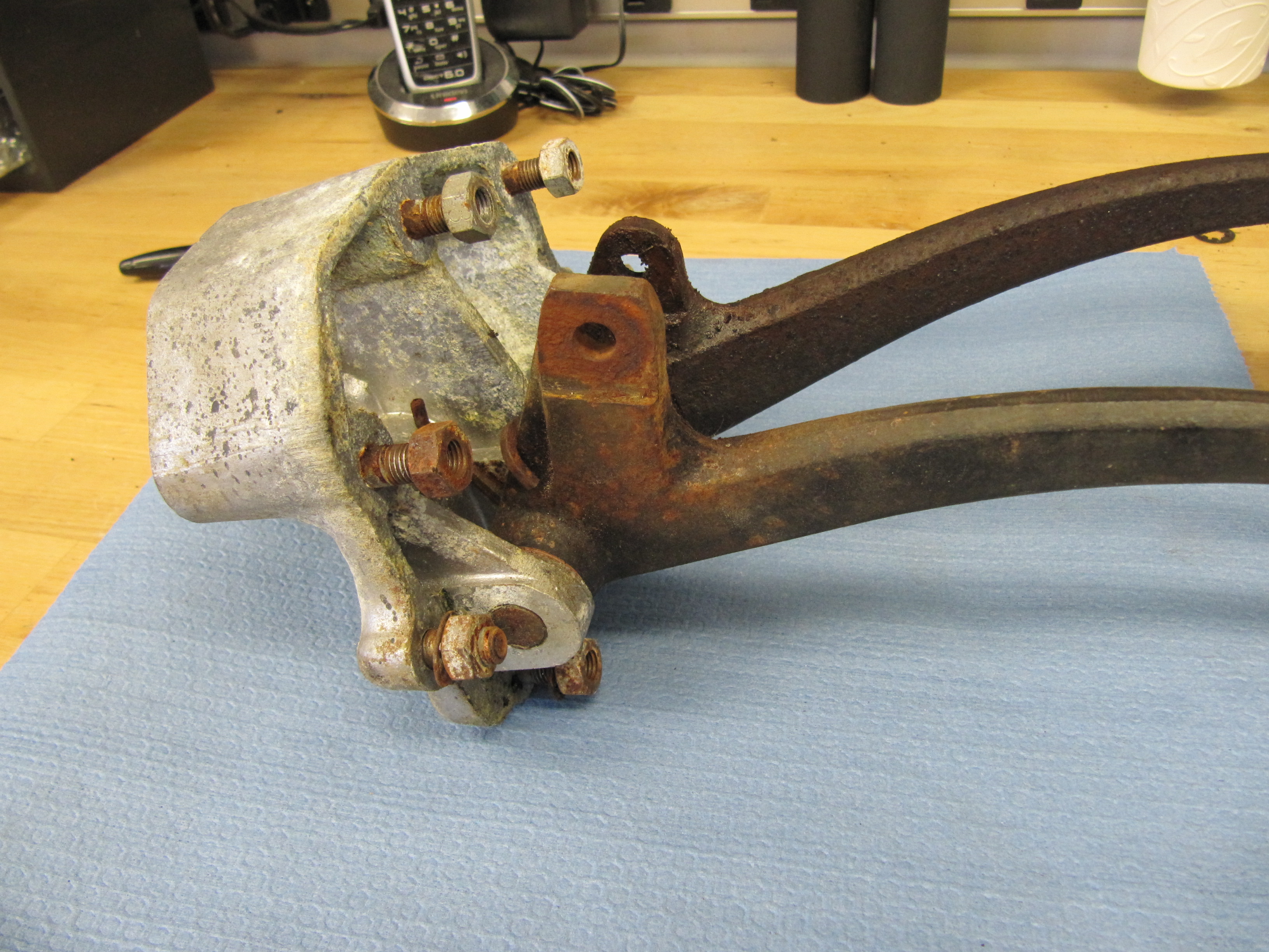
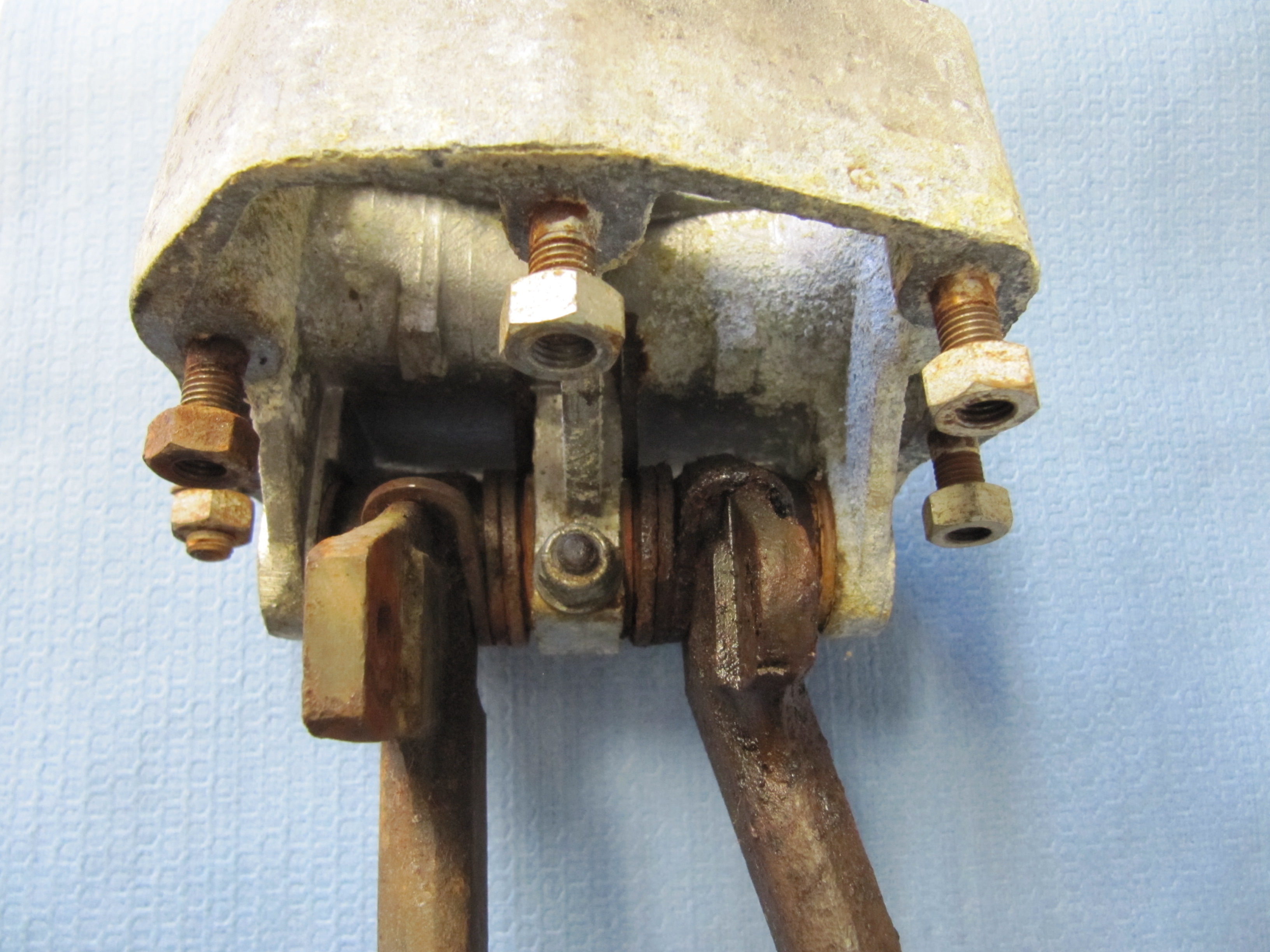
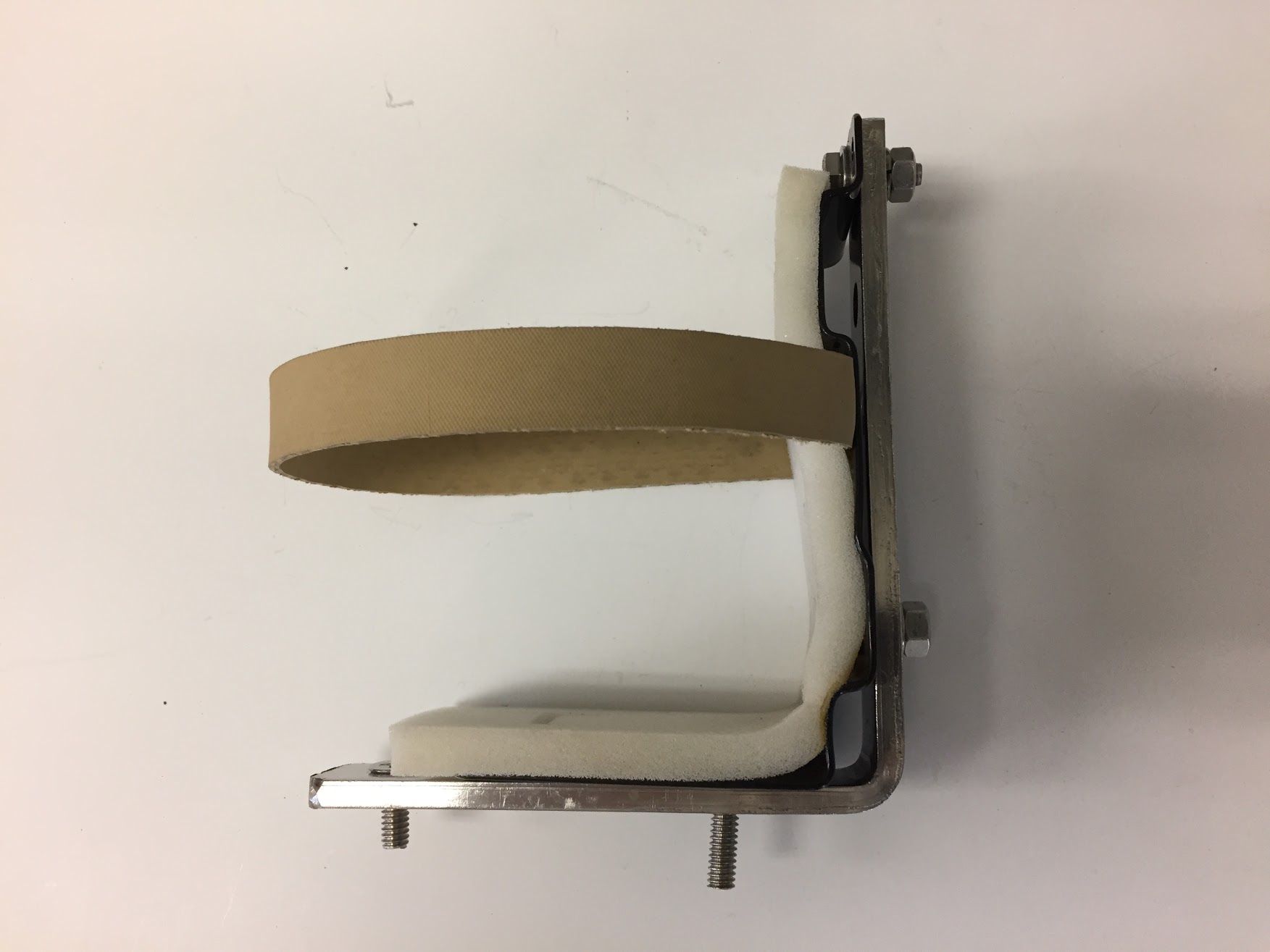
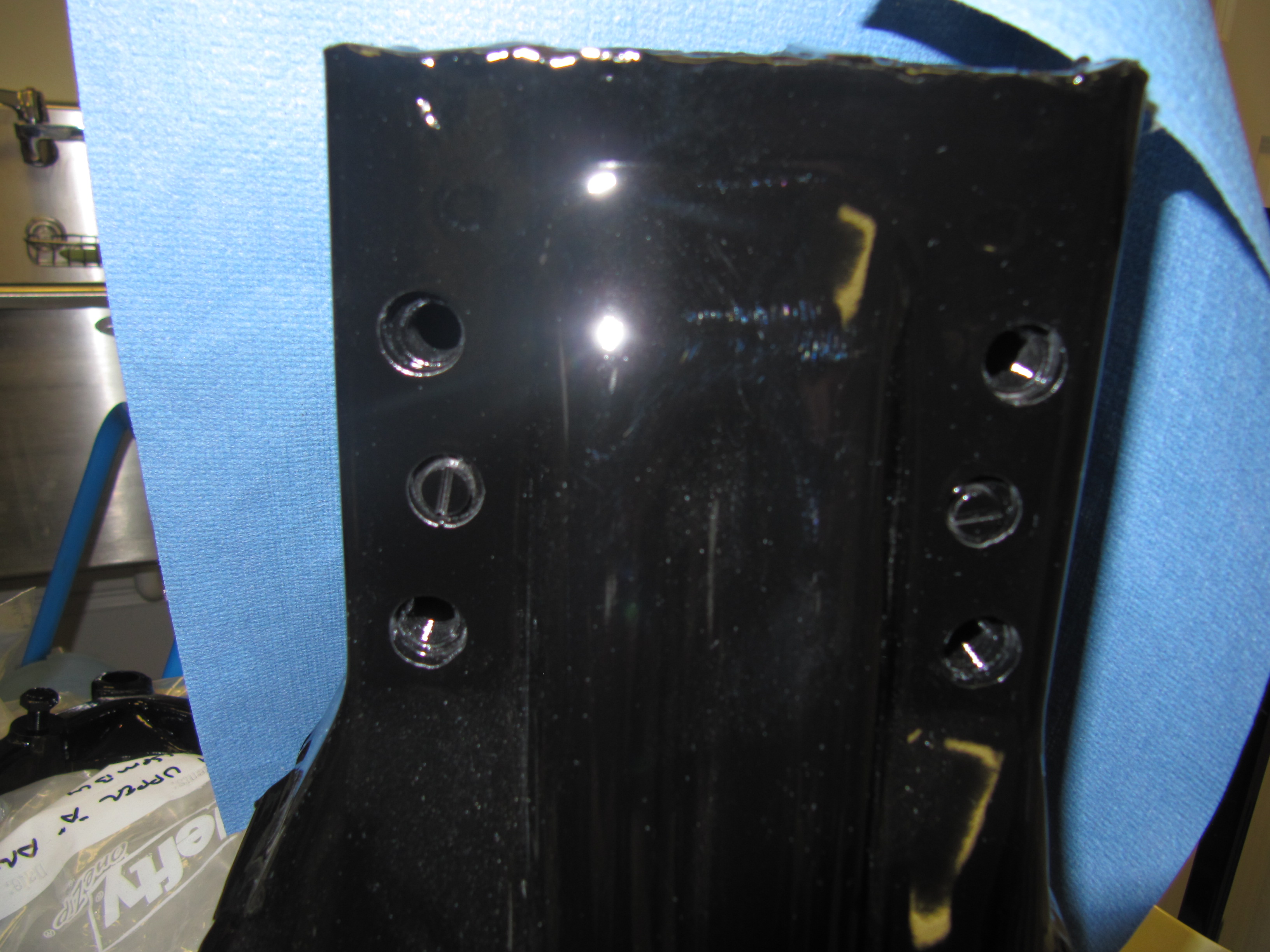
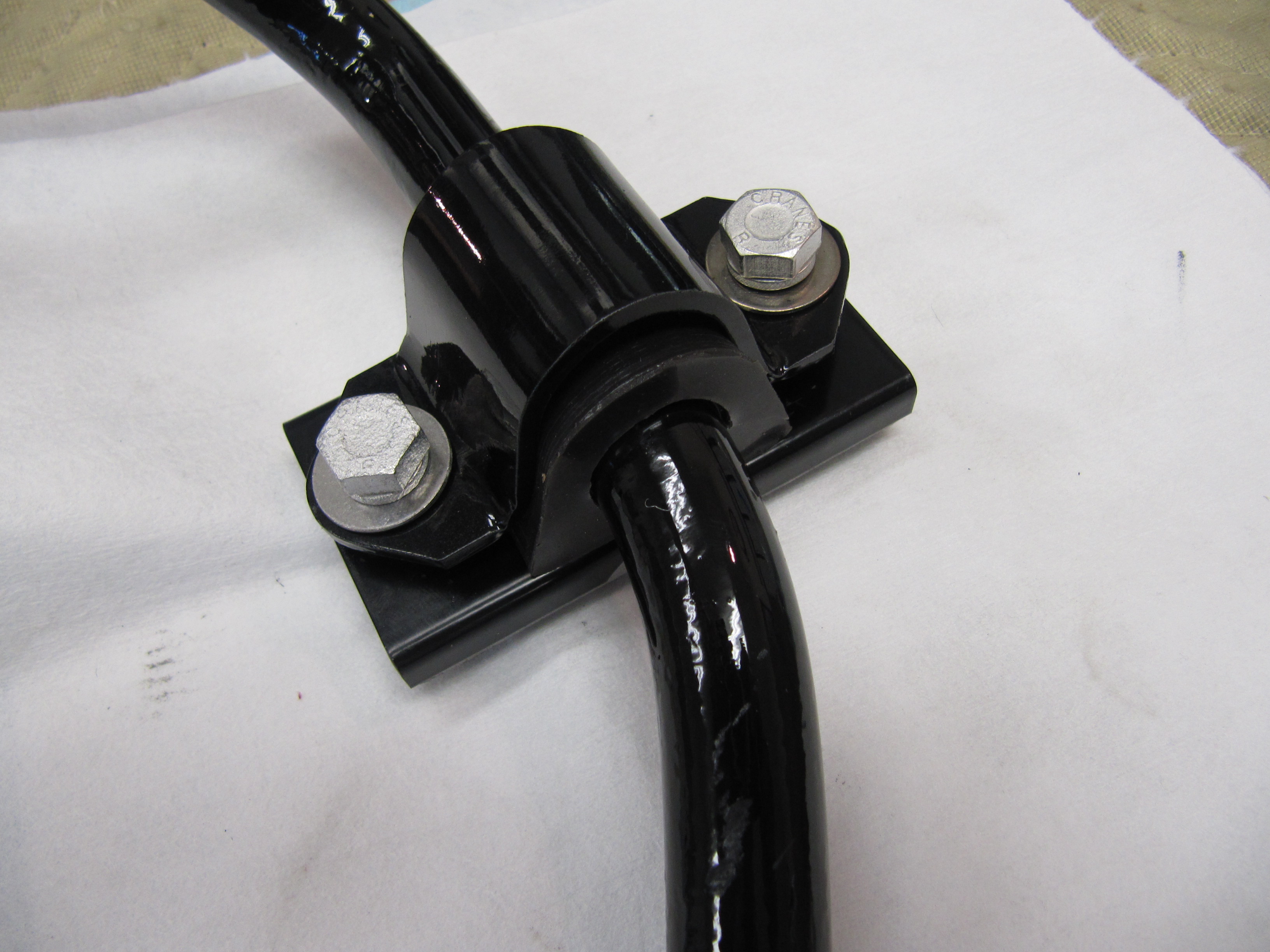
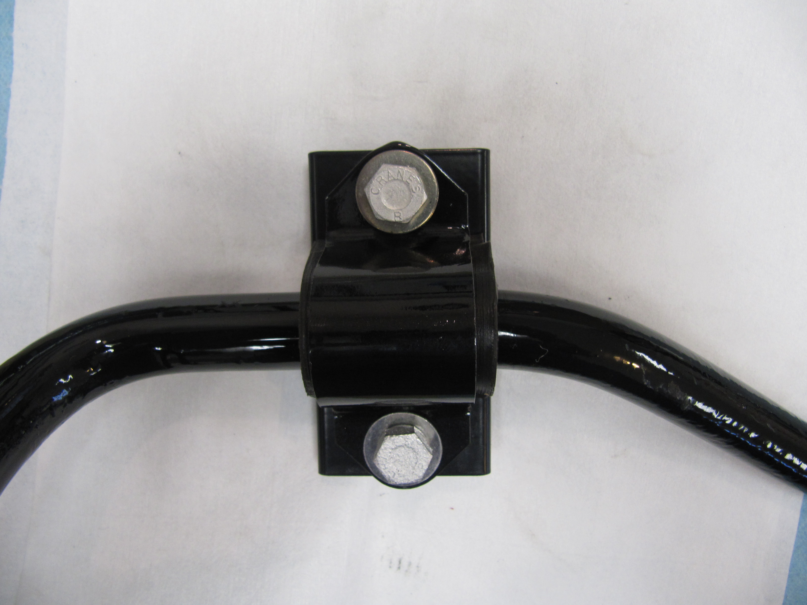
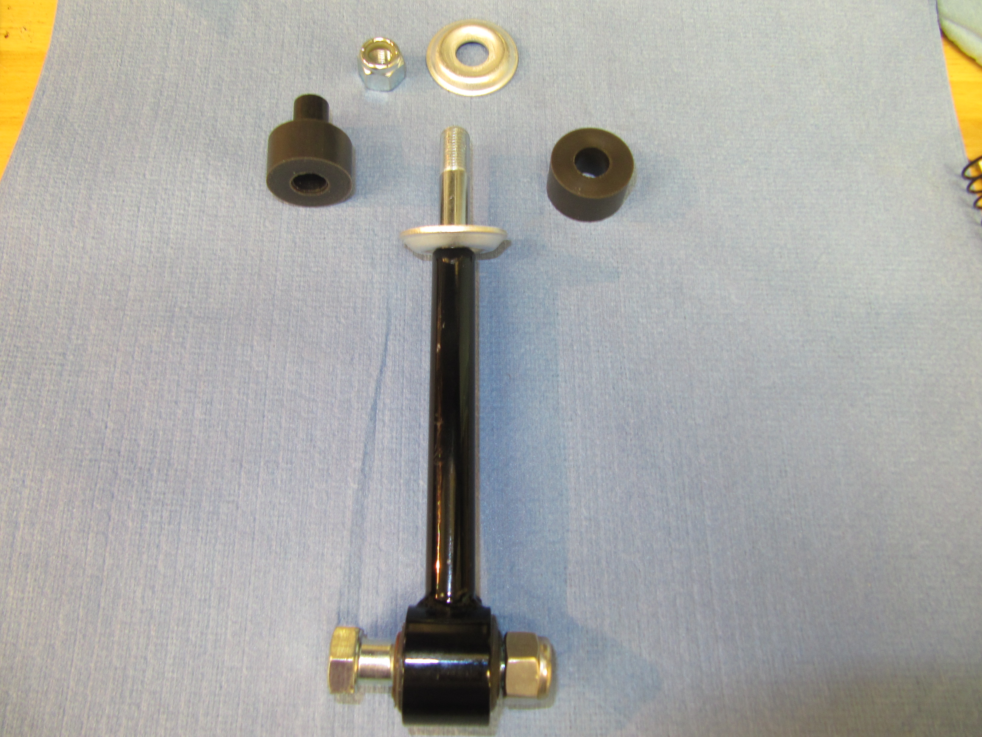
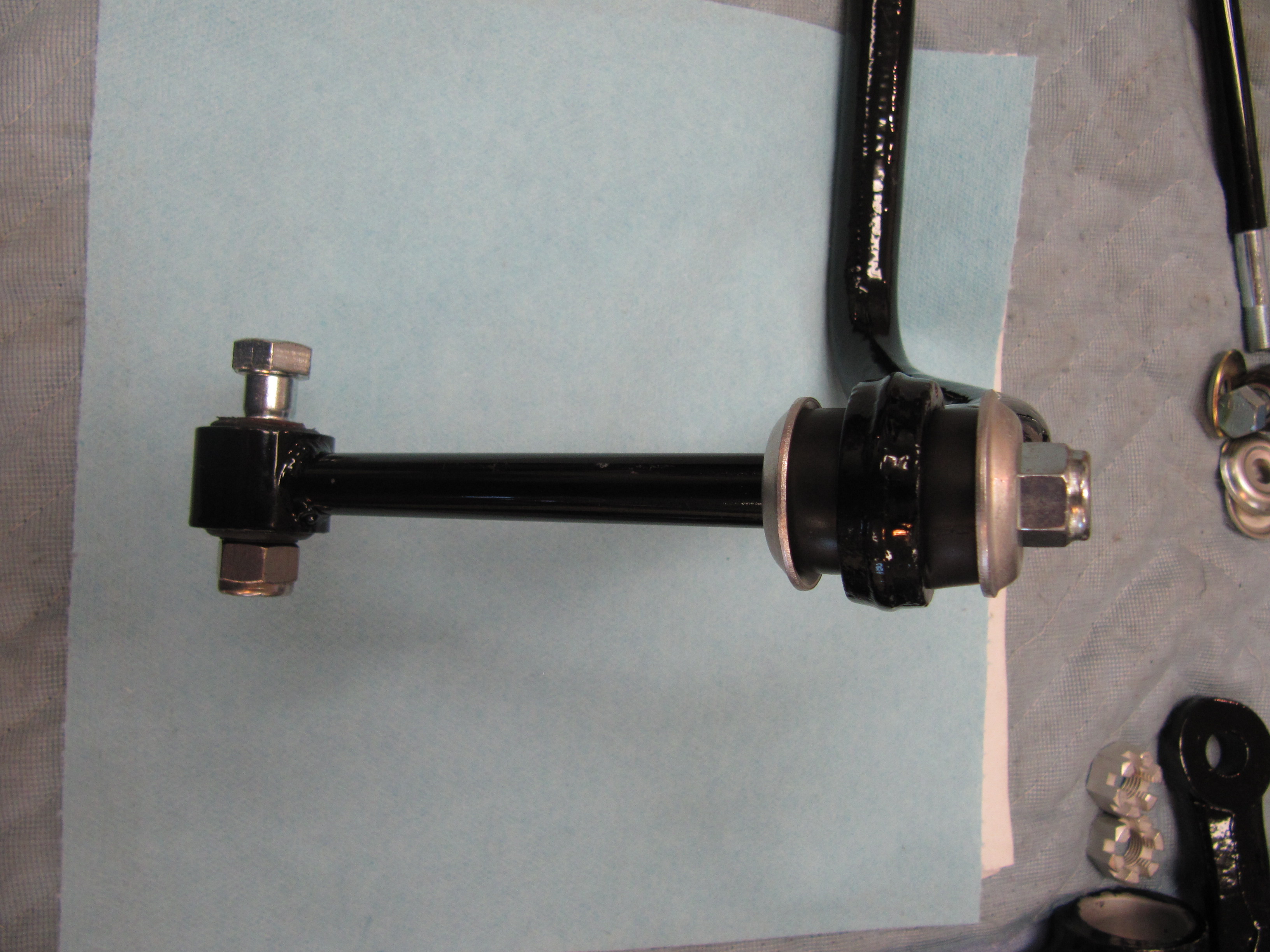
I know that Jaguar was very cost conscious, but these brackets are pretty primitive. Note the saw cuts on the tensioner pulley below:
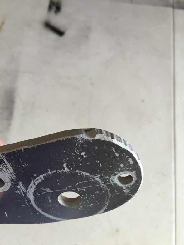
Tensioner Pulley Bracket
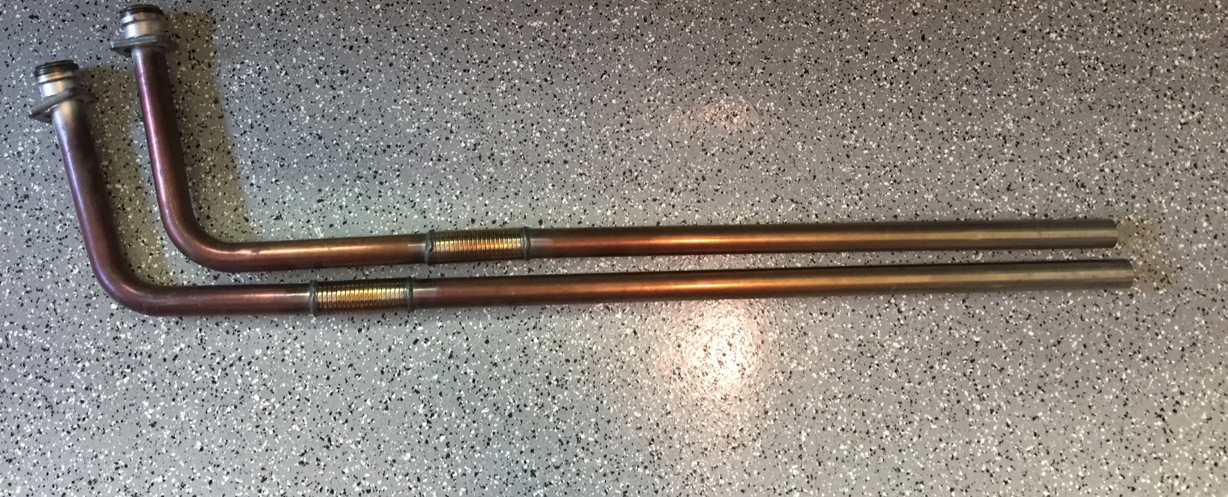
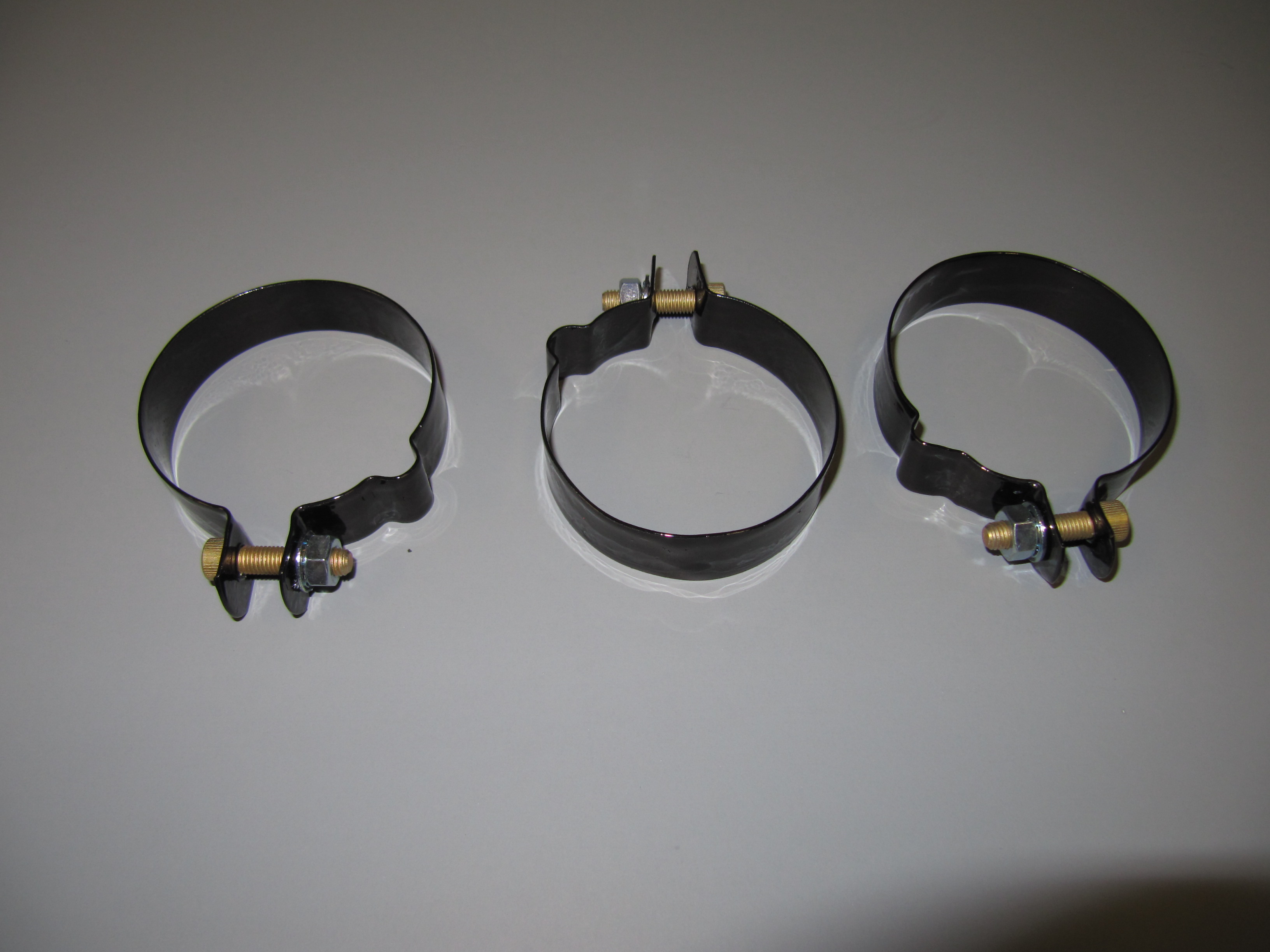
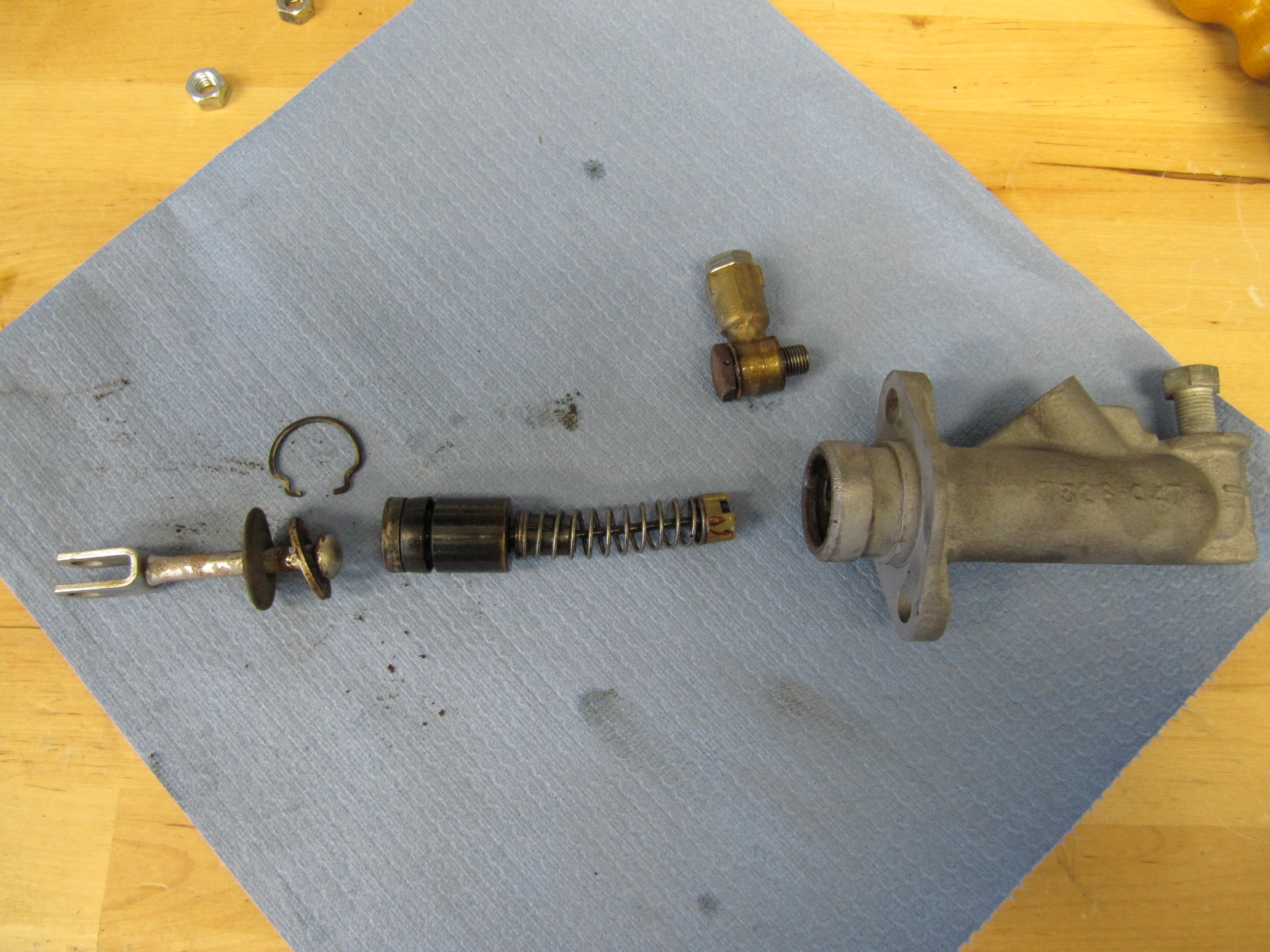
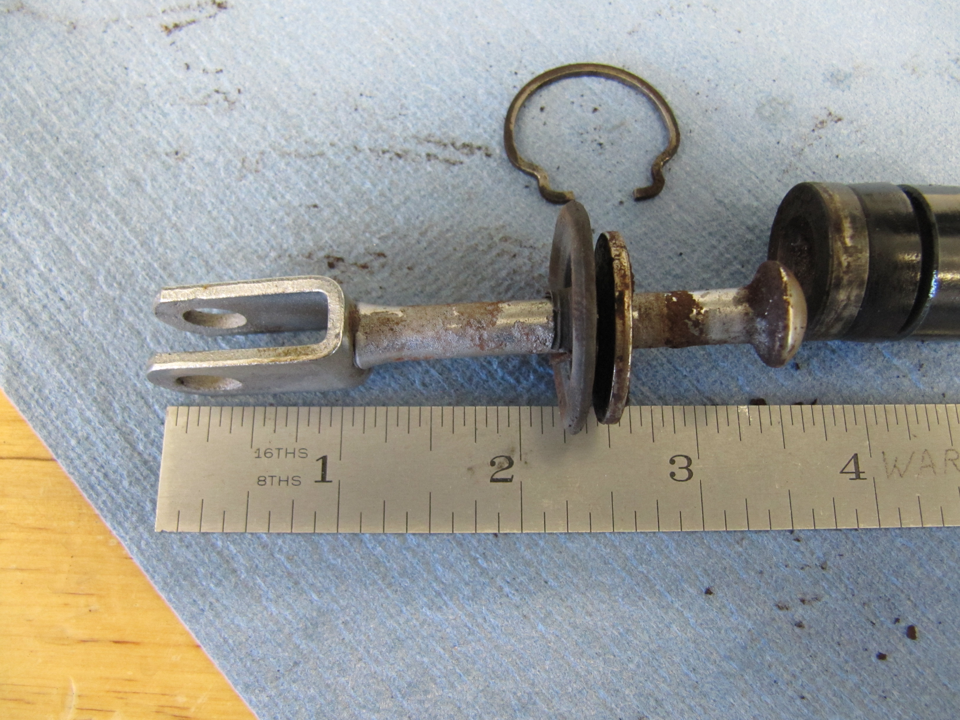
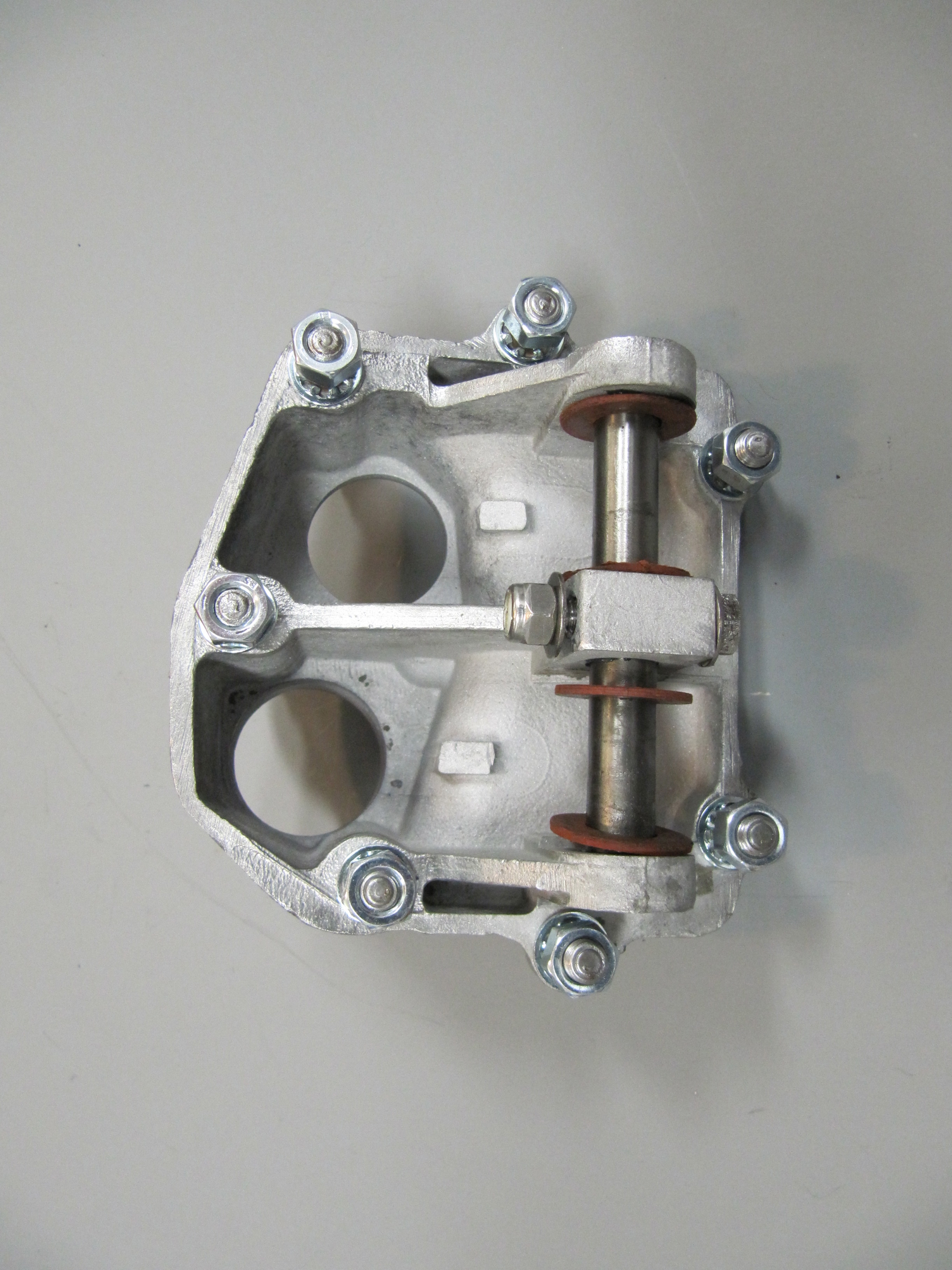
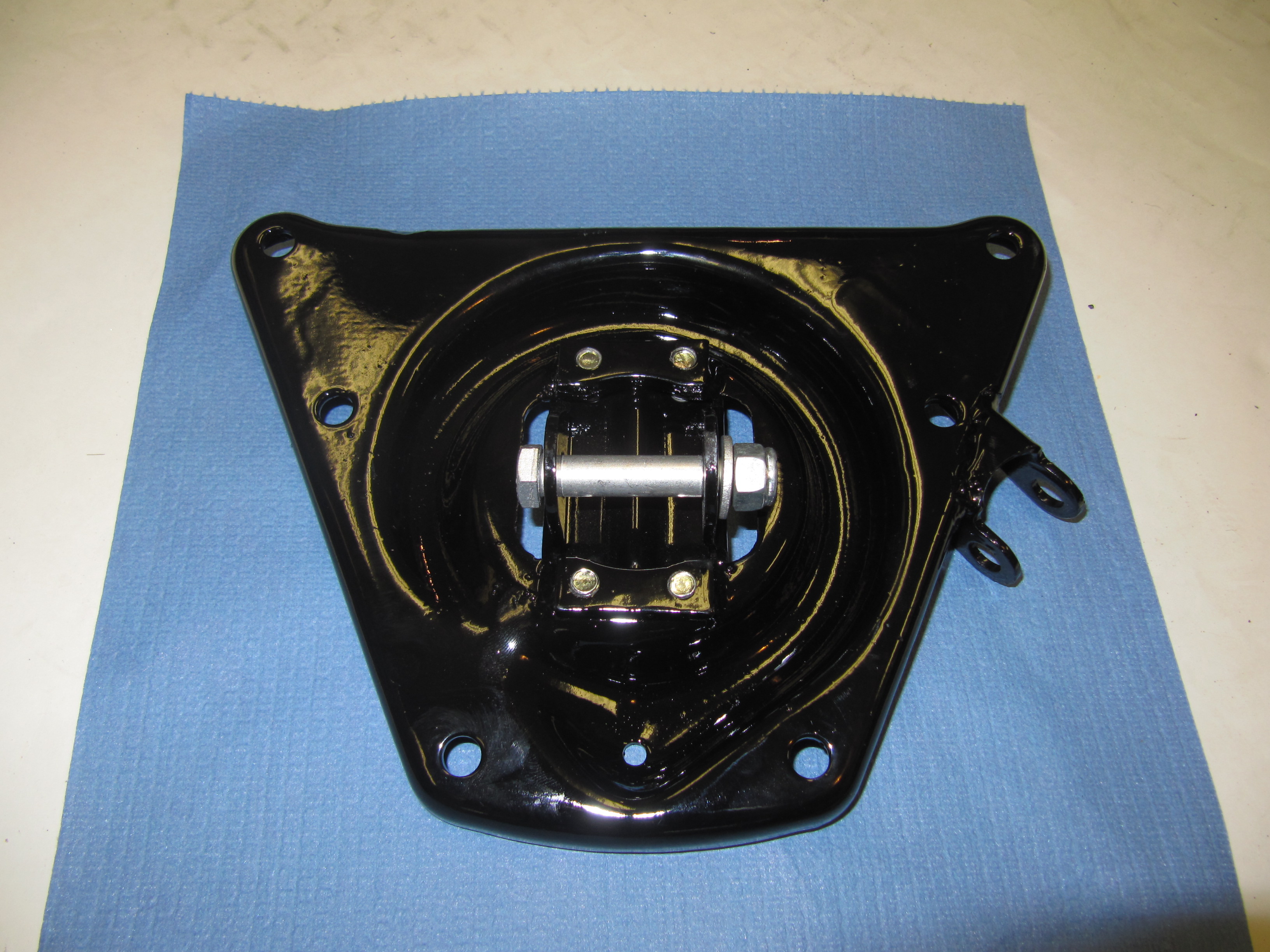
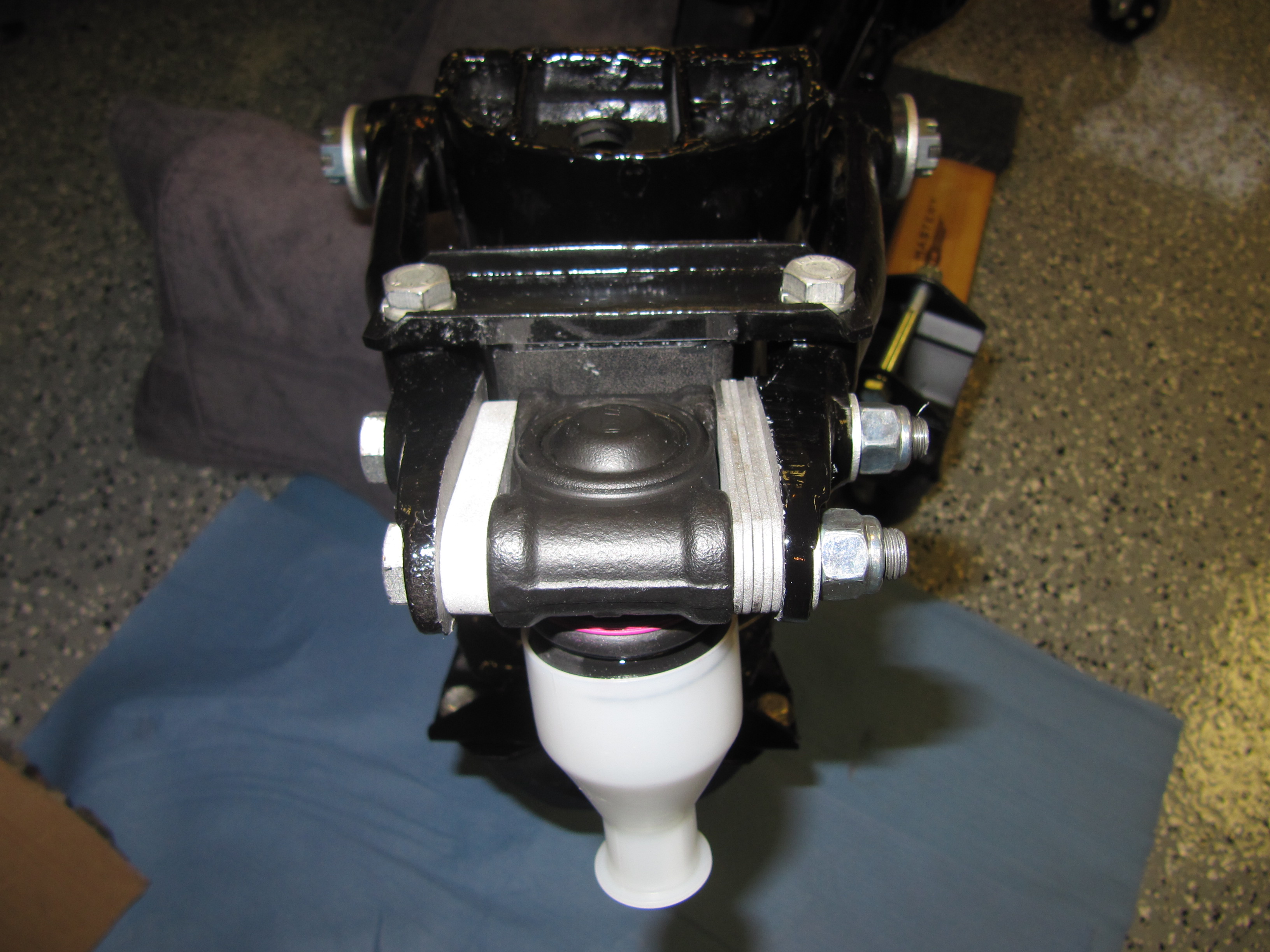
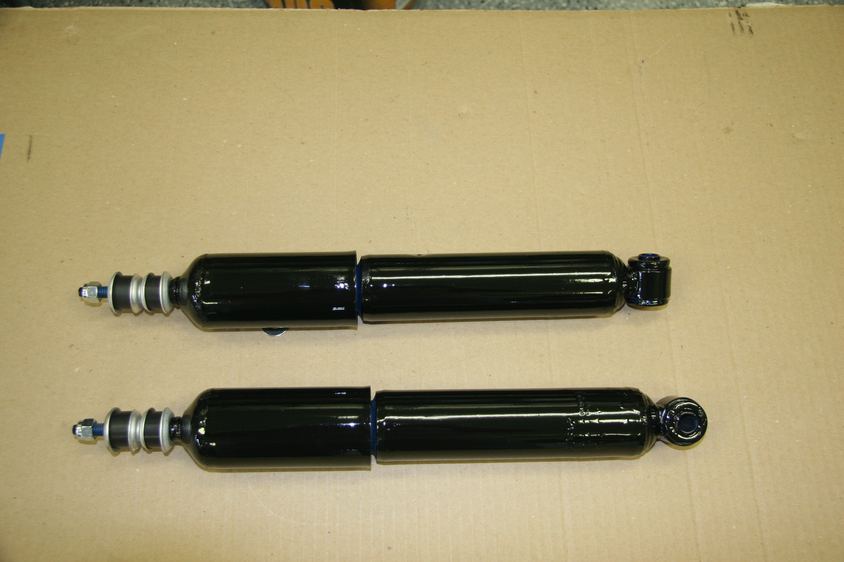
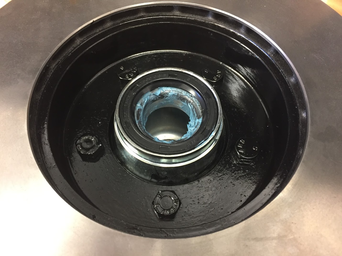
These are a couple of close up images of the tensioner pulley on its mounting bracket with the adjustable eccentric arm for tensioning the belt.
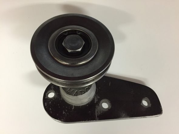
Tensioner Pulley MK2
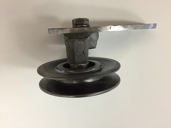
Tensioner Pulley MK2
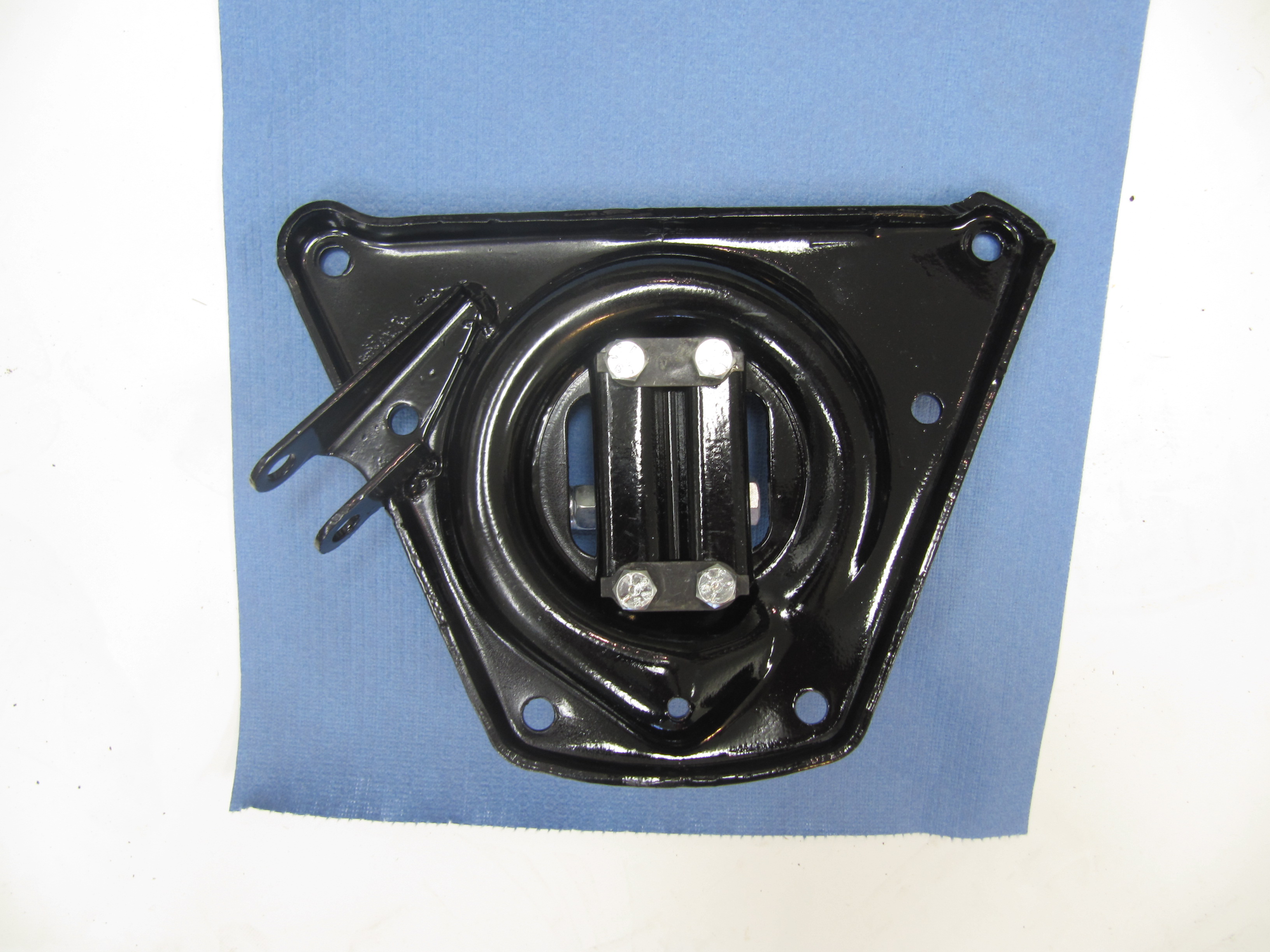
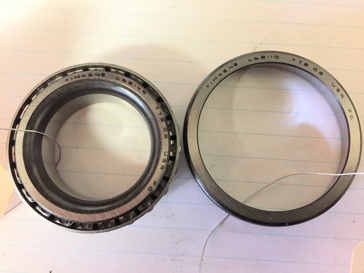
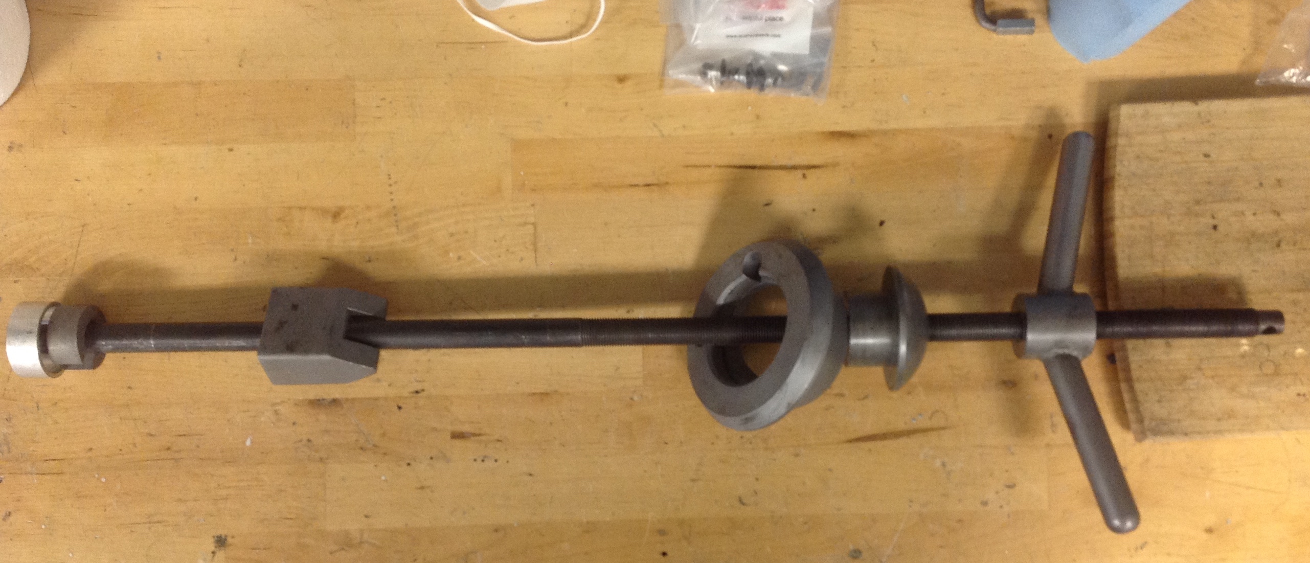
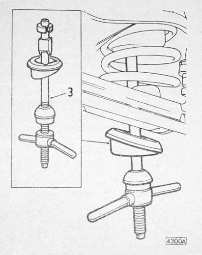
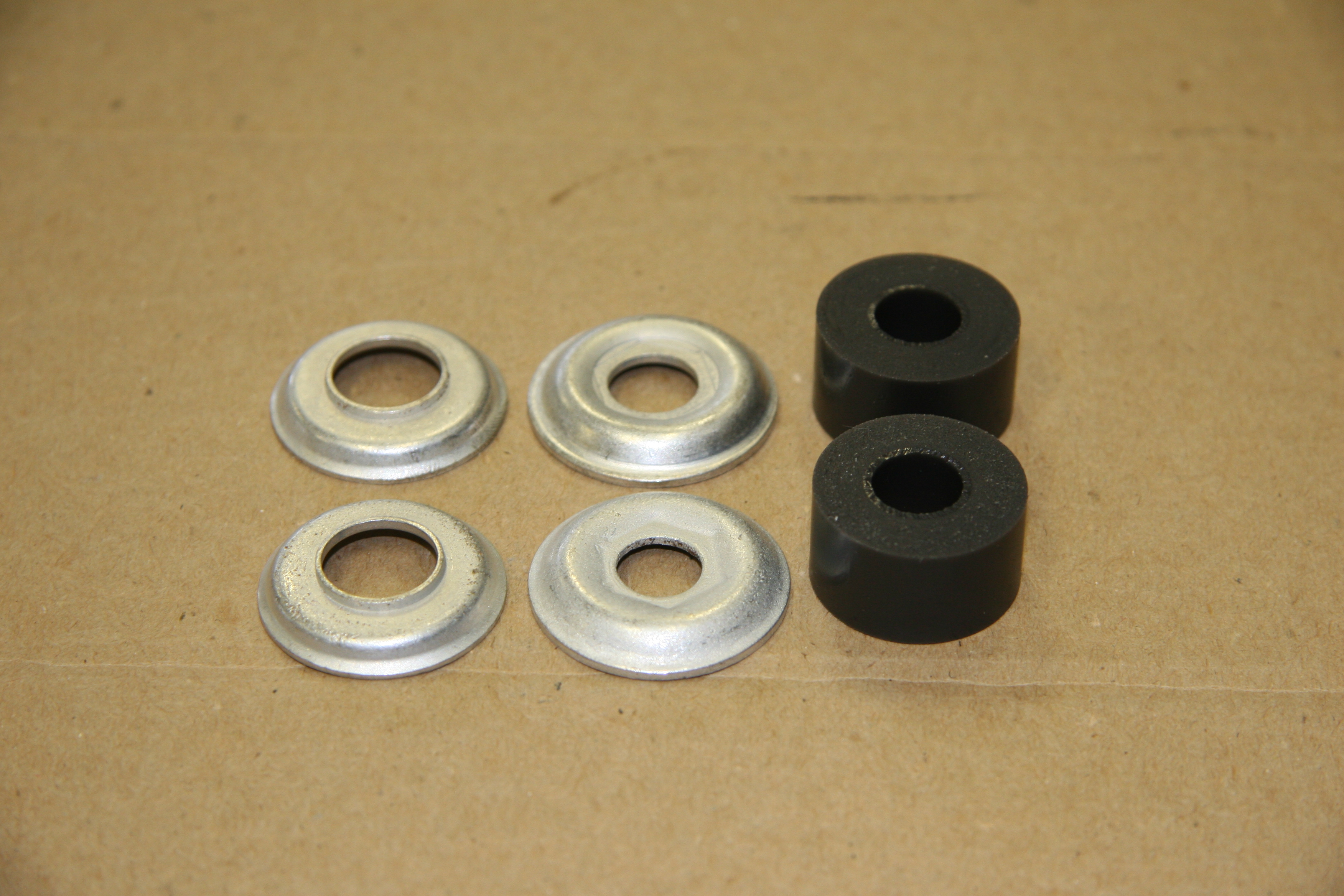
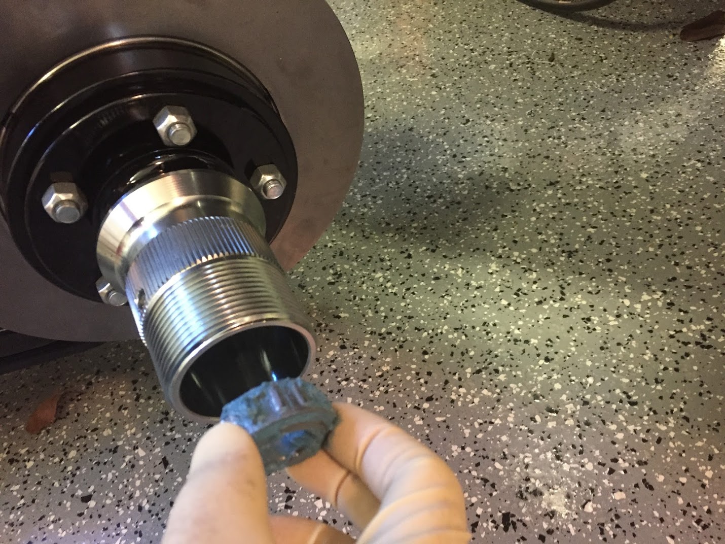
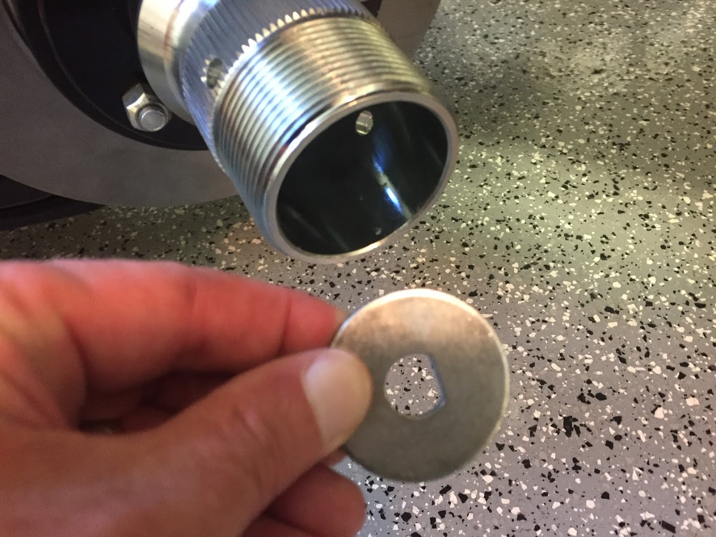
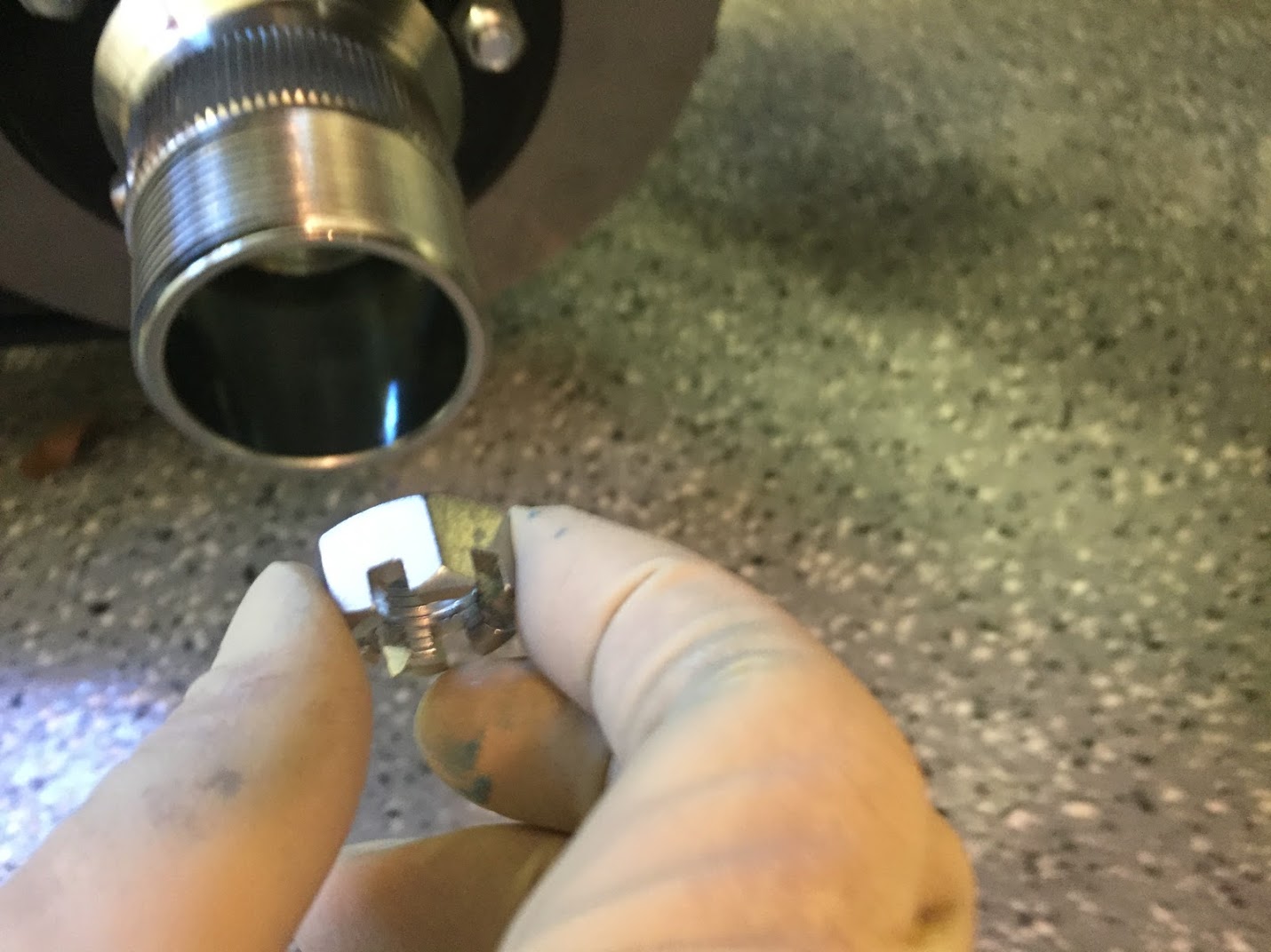
I removed the 7/16 ” shoulder bolt connecting the pulley to the MARCO eccentric alarm. I was then able to remove the circlip that was retaining the bearing in the pulley. I then drifted out the bearing and replaced it with a new bearing of the same model number which is 6203RS sourced from VXB.com Ball Bearings. 6203RS has a 17mm inside diameter, a 40 mm outside diameter, and is 12mm wide. I then reinserted the shoulder bolt through the pulley and a quarter inch spacer into the MARCO eccentric arm and tighten the pulley to the arm.
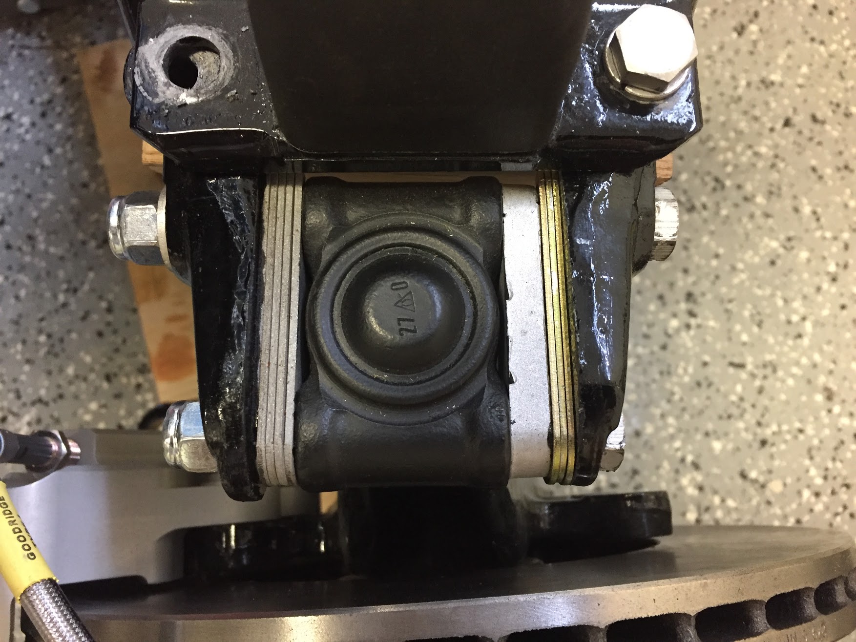
In this image you can see the MARCO lettering on the eccentric arm, the circle and the shoulder bolt.
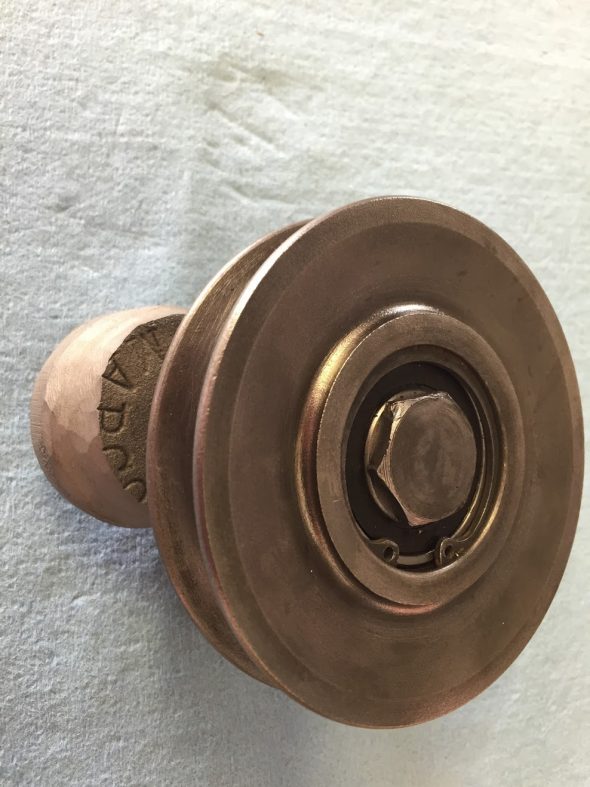
Tensioner Pulley and Marco Eccentric Arm
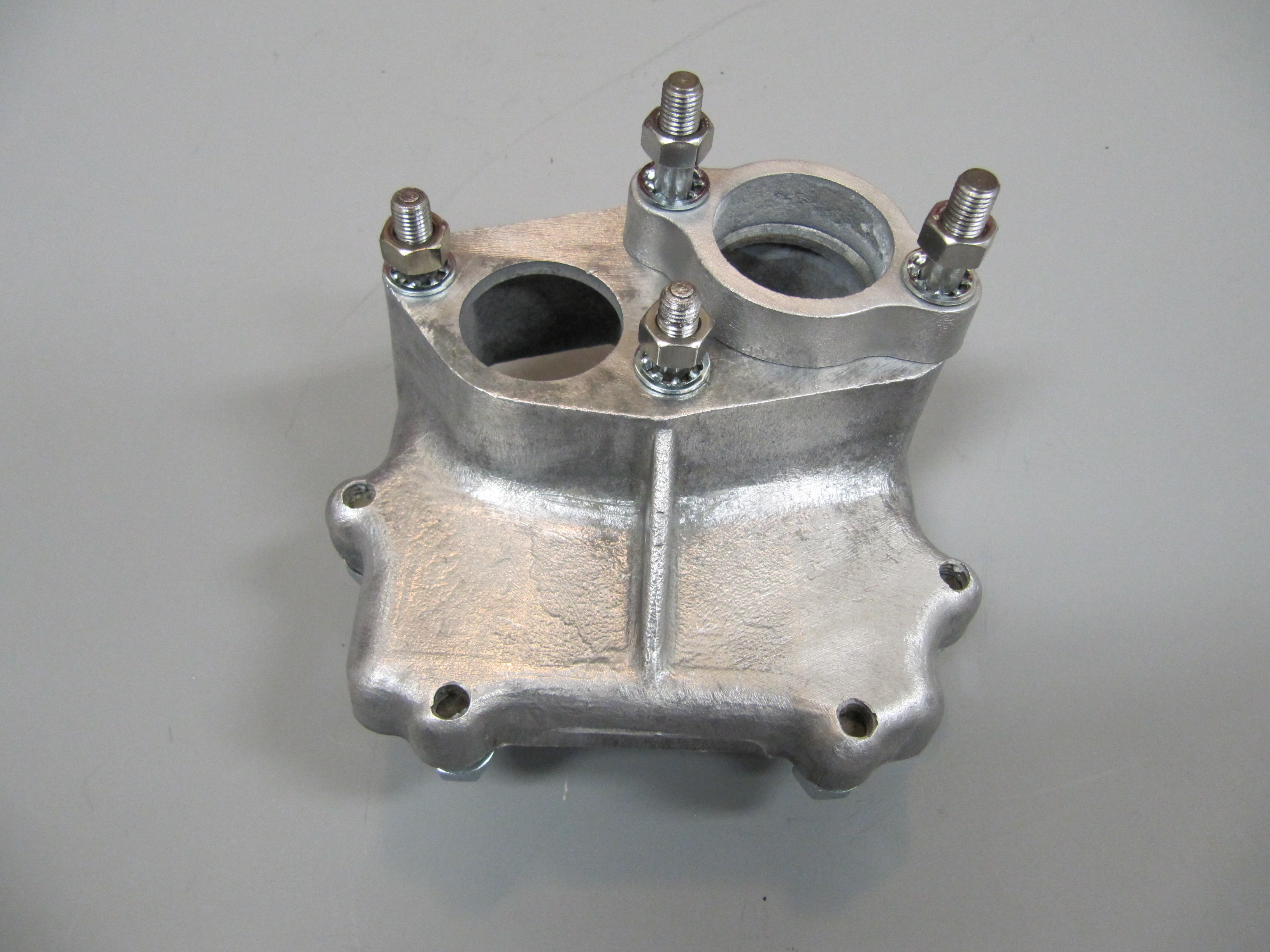
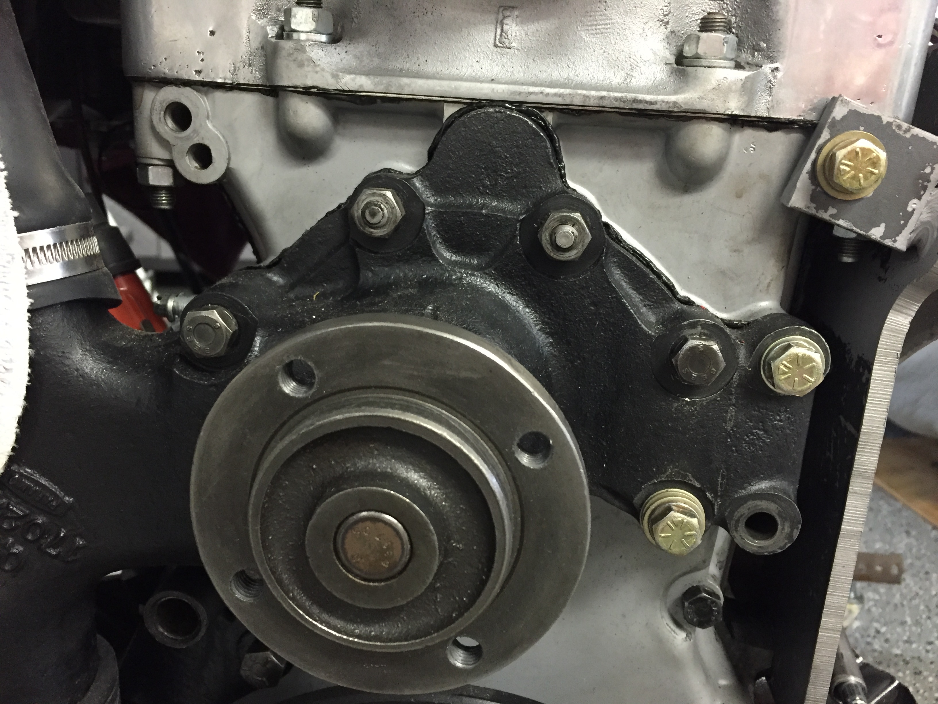
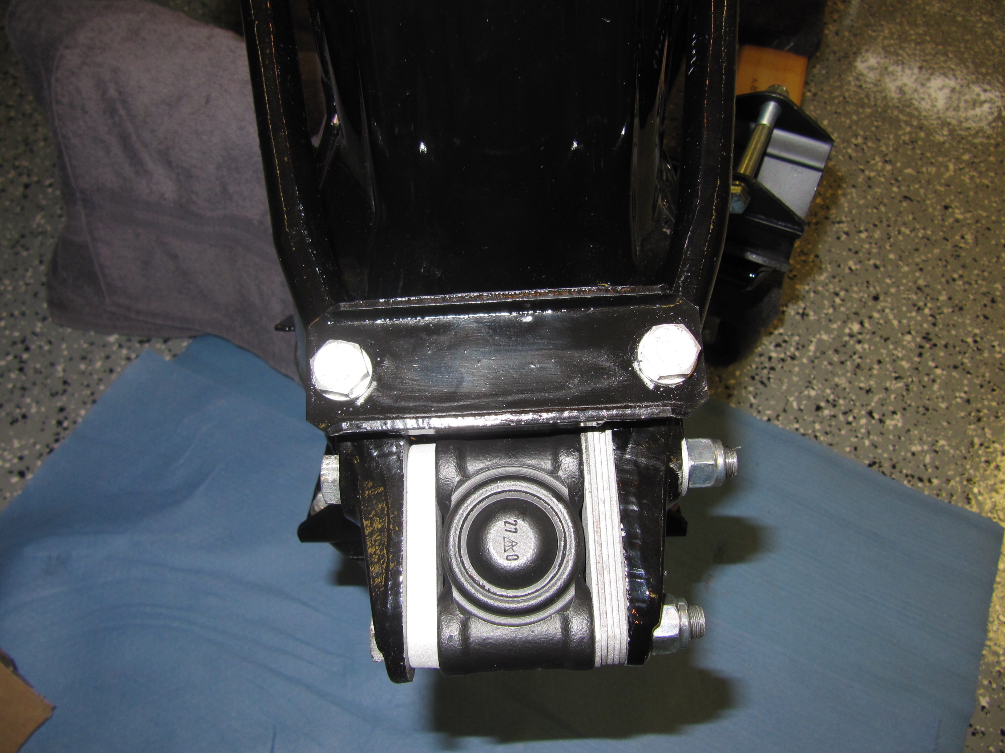
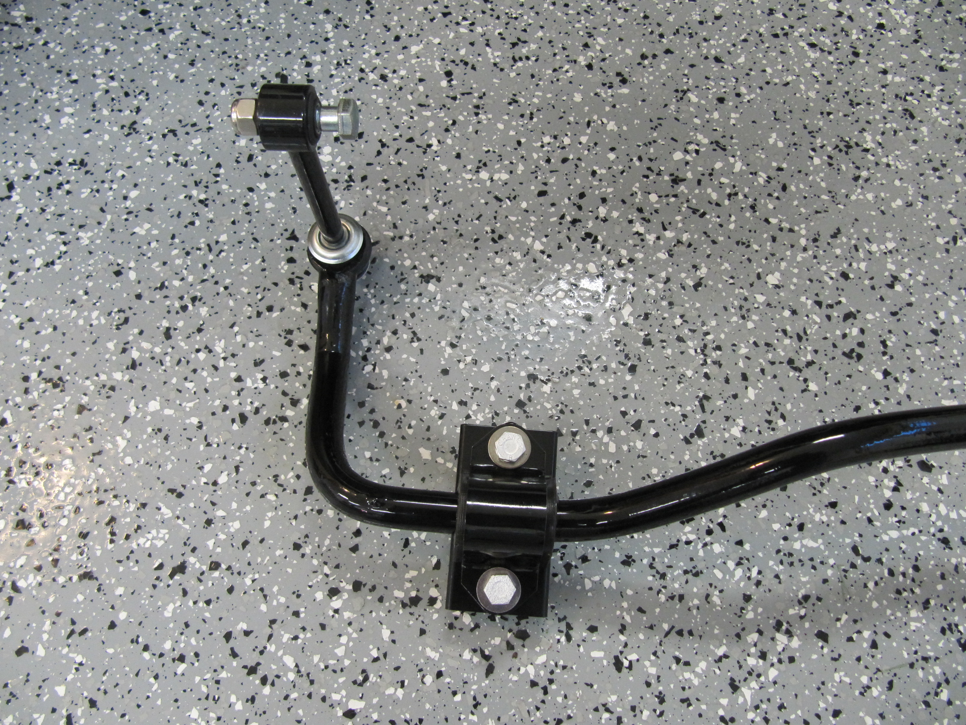
The tensioner pulley bracket is attached to the front of the engine with three bolts and spacers. I used drill bushings for spacers and they were all sourced from McMaster-Carr. The two center and upper studs for the water pump must be removed. I used a stud remover socket for 5/16″ studs to carefully remove the studs. Fortunately, they came right out!
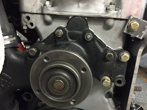
Water Pump Nuts and Studs to be Removed
Looking at the front of the engine, the upper LH bracket mount uses a 5/16″ – 24 x 3-1/4″ bolt and split washer with a 5/16″ ID, 5/8″ OD and 1-1/4″ long drill bushing spacer. The center and RH mounts for the bracket use coarse thread 5/16″ – 18 x 2″ bolts (they replace the original water pump studs) with split washers and 5/16″ ID, 5/8″ OD, and 1/2″ long drill bushing spacers. Also in the image is the 1/2″ – 20 x 1″ hex head bolt used to attach the pulley eccentric arm to the mounting bracket.
Tensioner Pulley Mounting Plate Drill Bushing Spacers Installed
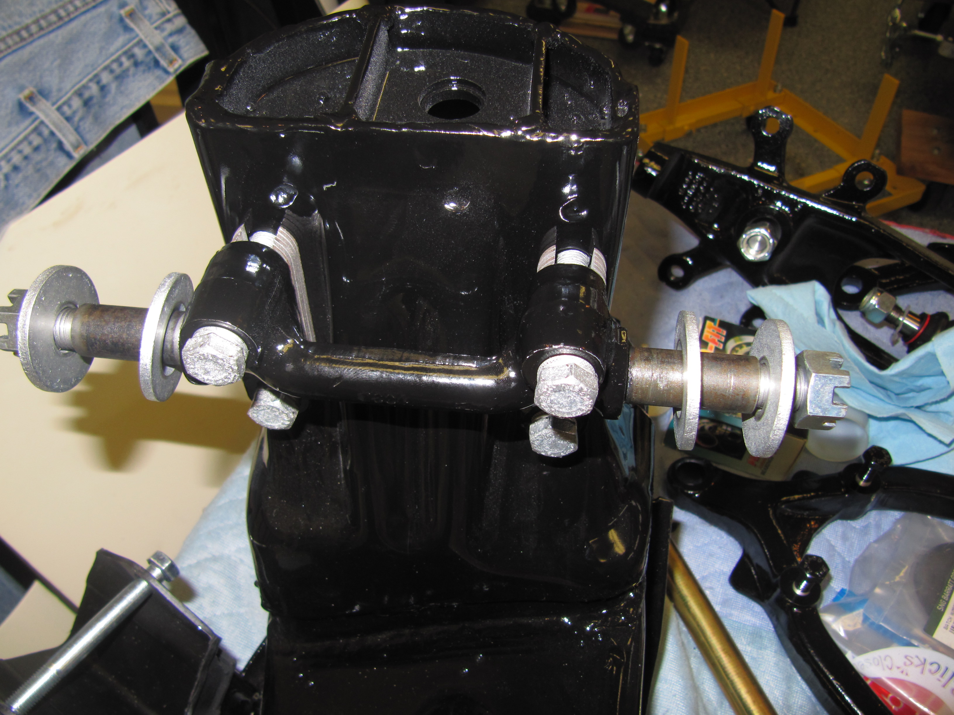
Tensioner Pulley Mounting Bracket Installed
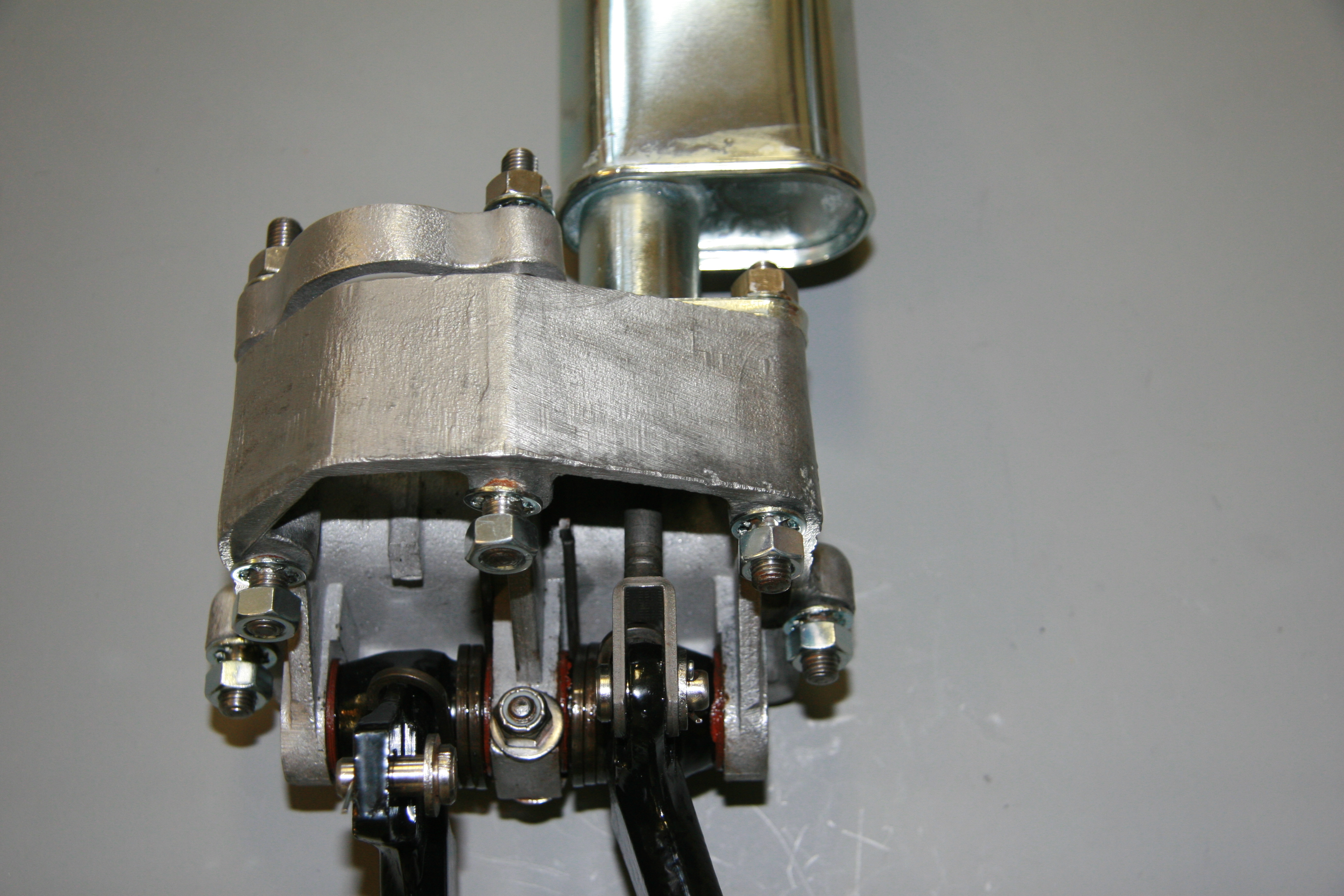
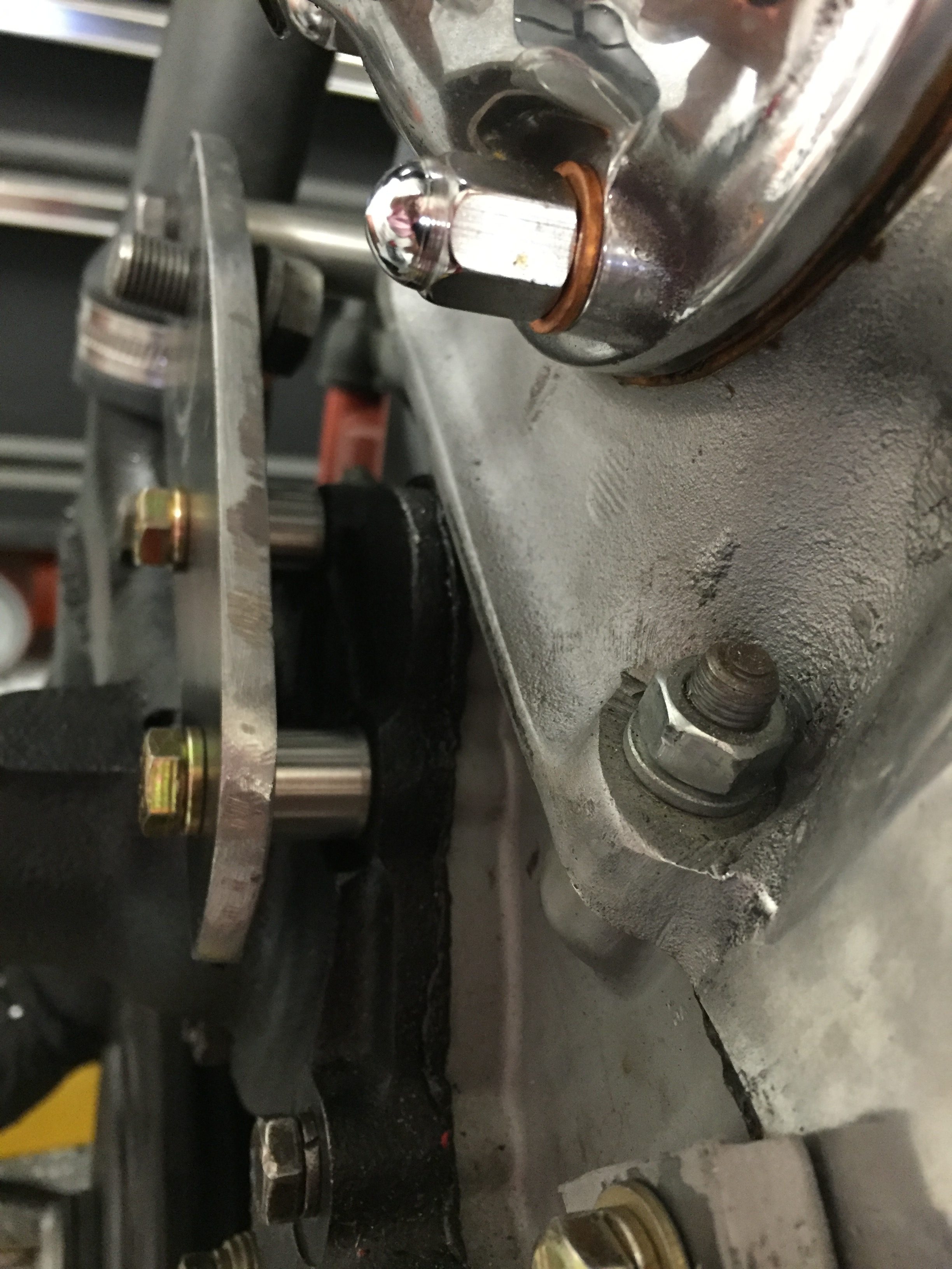
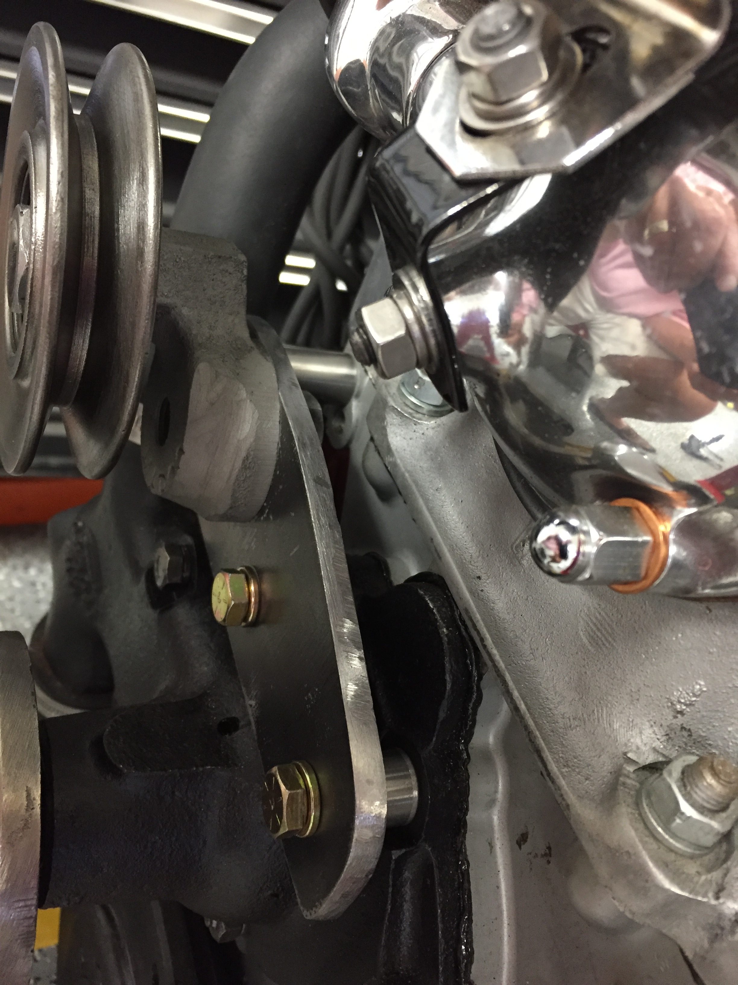
The tensioner pulley mounted to the eccentric arm is then secured to the bracket with the 1/2″ – 20 x 1″ bolt.
Tensioner Pulley Eccentric Arm Mounting Bolt
Tensioner Pulley Eccentric Arm Installed
Tensioner Pulley on Mounting Plate and Installed
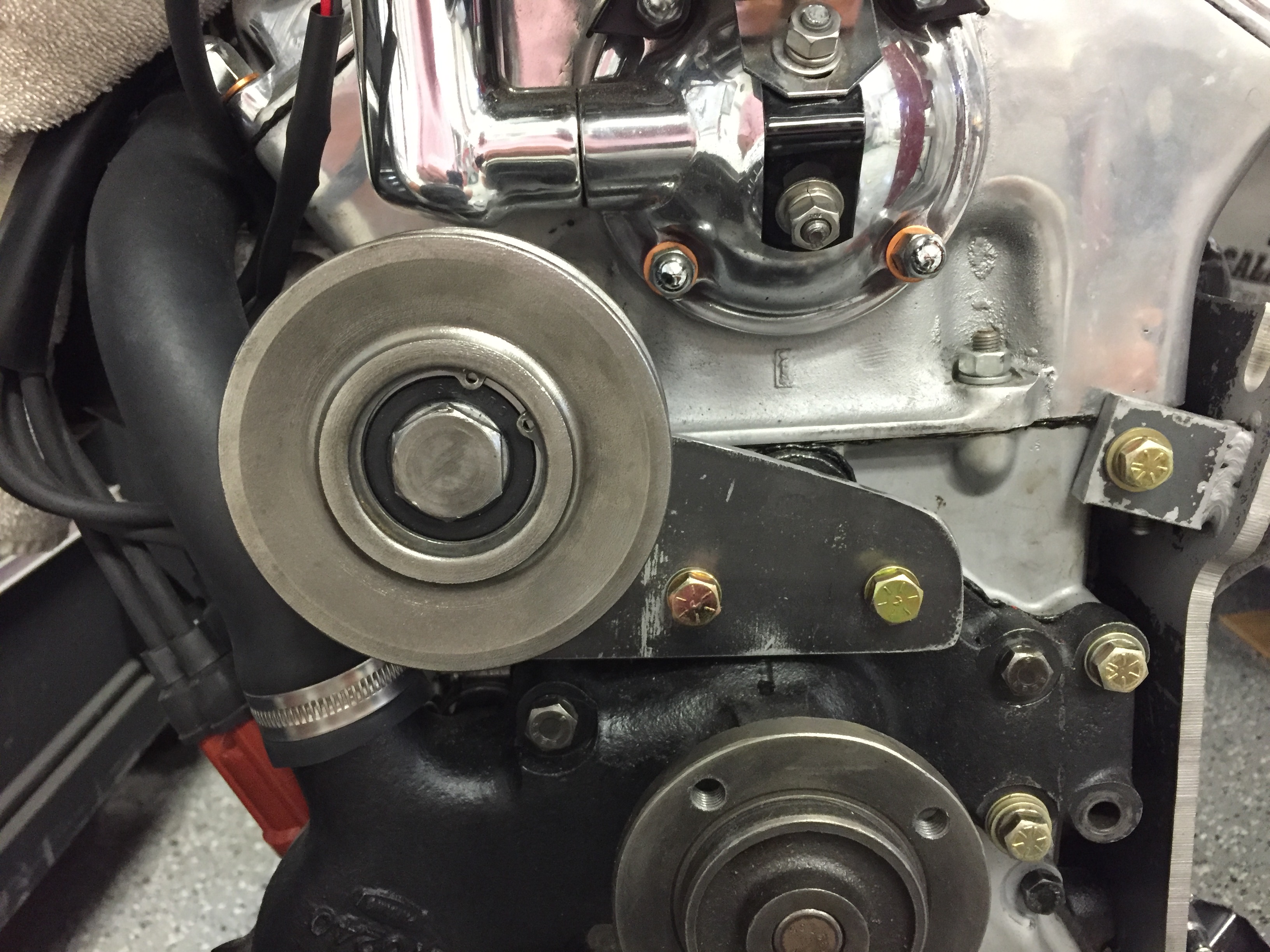
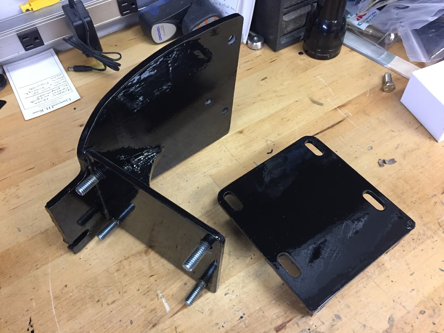
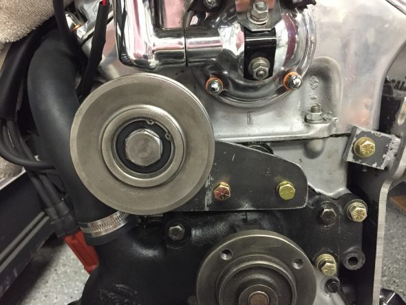
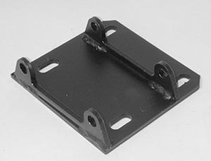
The compressor bracket is quite a substantial piece. Made of 1/4″ steel plate. The two images below show a trial fitting of the bracket to the engine block. It is secured with three 3/8″-24 x 1″ grade 8 bolts and washers on the side of the block and with one 5/16″ bolt at the front of the engine through the timing chain cover.
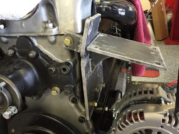
Compressor Bracket Trial Fitting
Compressor Bracket Trial Fitting
The curvature in the mounting bracket in the second photo is an optical illusion! It is a flat piece of steel with one angled bend as seen in the first image above.
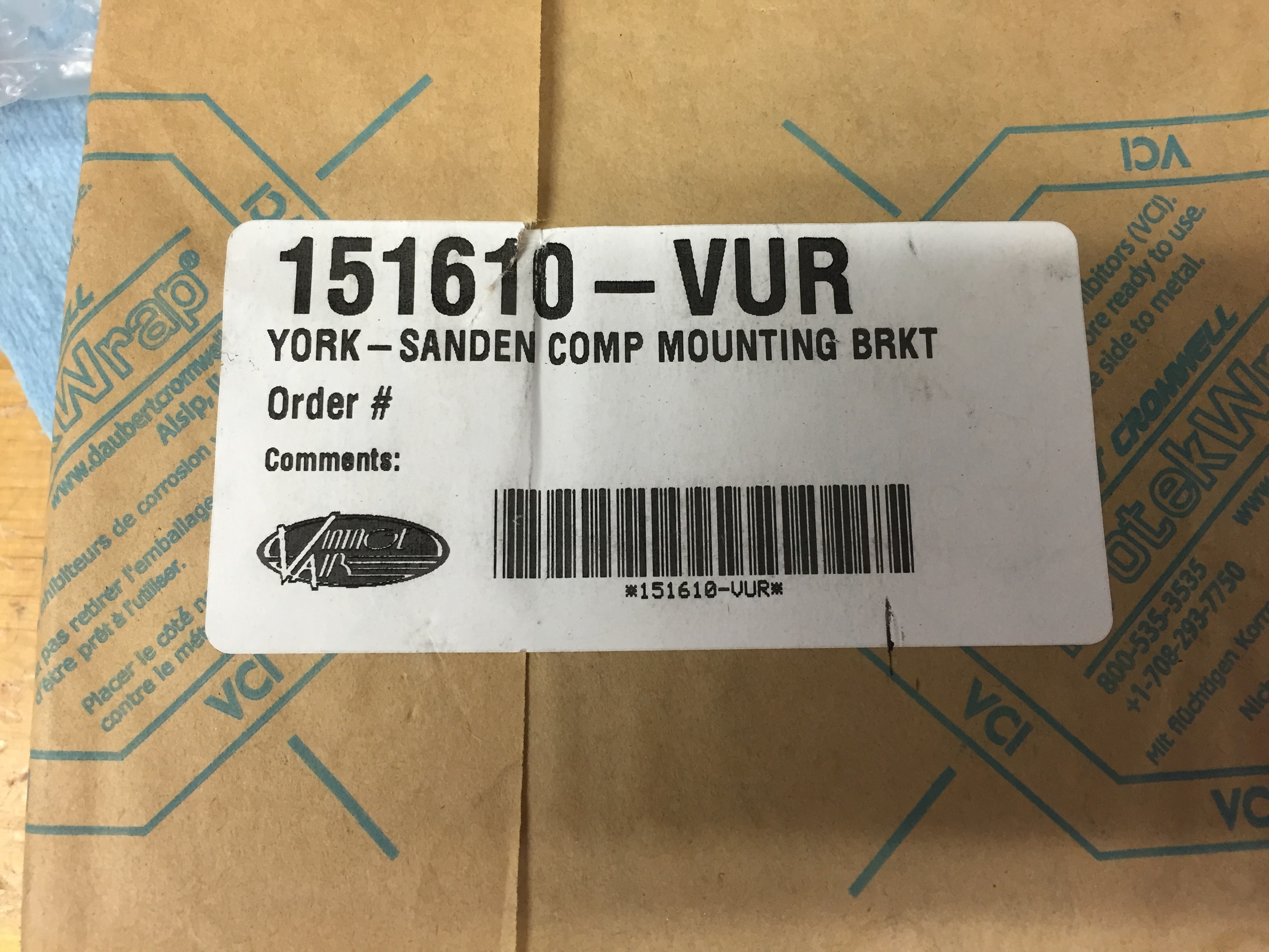
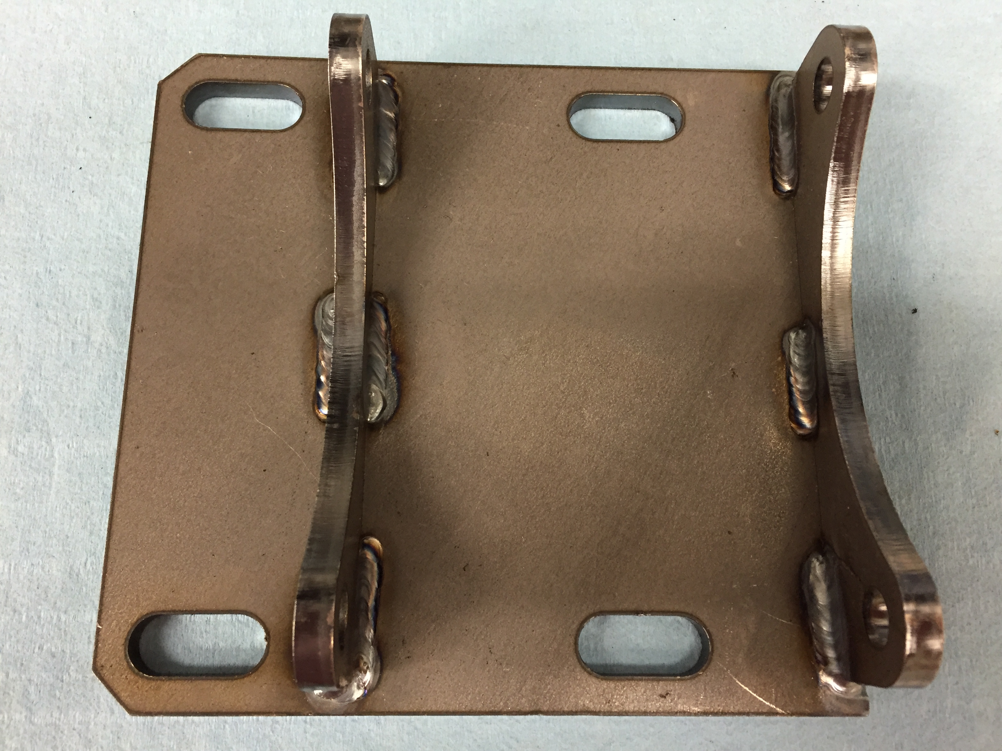
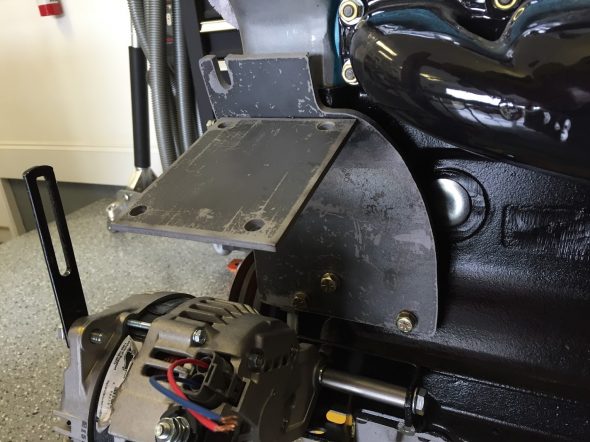
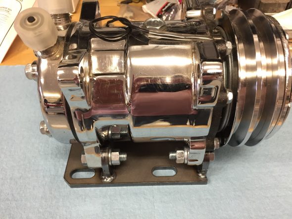
As mentioned previously, the bracket was made for the mounting of a York compressor and I am using a Sanden unit. To accommodate the Sanden Unit I purchased a York-to-Sanden conversion bracket from Vintage Air that sits on top of the bracket in the image above. A fasteners kit with all the hardware needed to interconnect the two brackets and mount the compressor comes with the bracket.

Vintage Air York to Sanden Mounting Bracket 151610-VUR

Vintage Air York to Sanden Mounting Bracket
Vintage Air York to Sanden Mounting Bracket Installed
After ordering the conversion bracket from Vintage Air, I discovered that there is at least one other similar, but not identical, bracket that would have been the better part for me. The curvature in the front mount of the bracket shown in the image above conflicts with the front of the Sanden Compressor if one needs to mount the compressor in front of the bracket attachment ears. I suppose it would work fine if the compressor was mounted behind the bracket mounting ears. The other commonly available bracket looks like this:
Square Faced Bracket
Note the mounting brackets are not curved or arched. The square cuts clear the front of the Sanden Compressor. Rather than returning and reordering the proper bracket I just used a grinder to replicate the square cut front. The rear curvature is not an issue. Oh well, live and learn.
Following my little diversion, I did mount the compressor and the conversion bracket to the MK2 bracket.
Compressor to Conversion Bracket
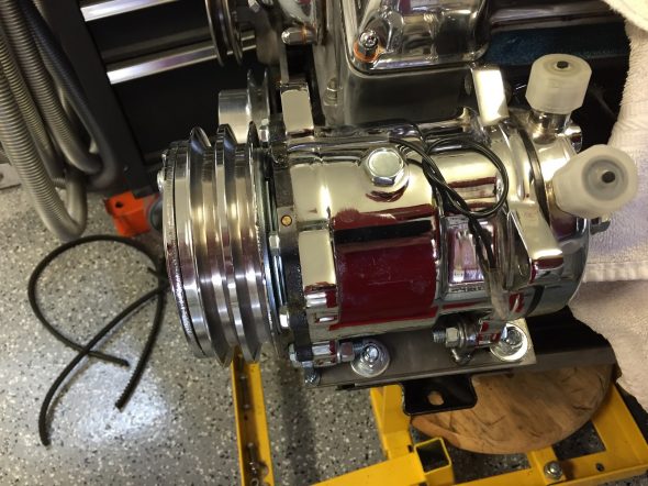
Compressor and Conversion Bracket Mounted to Engine Bracket
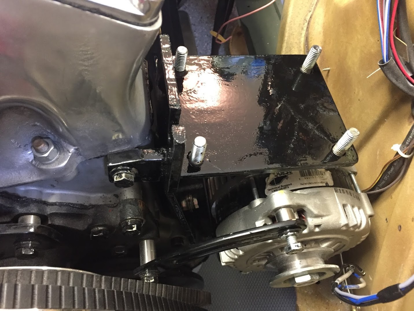
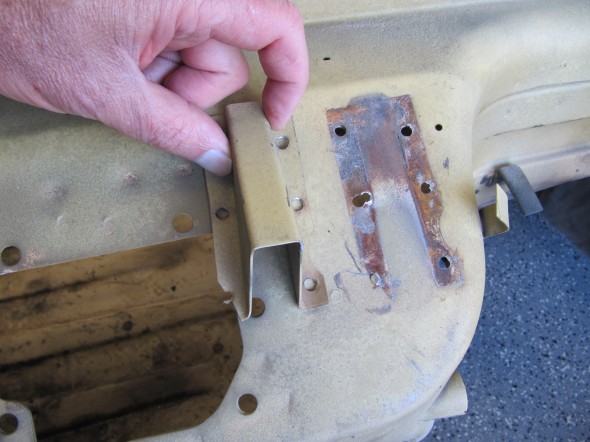
The exercise of installing air conditioning in the MK2 is a trial and error process. The major challenge is the lack of space under the bonnet and in the interior. Once I had the engine in the car and I began installing ancillaries such as the radiator, fan and fan shroud and etc. I quickly discovered that I could not get the fan shroud installed when the compressor was in place and if I tried to install the fan shroud first and then the compressor I could not access the mounting bolts for the York/Sanden mounting bracket to tighten them.
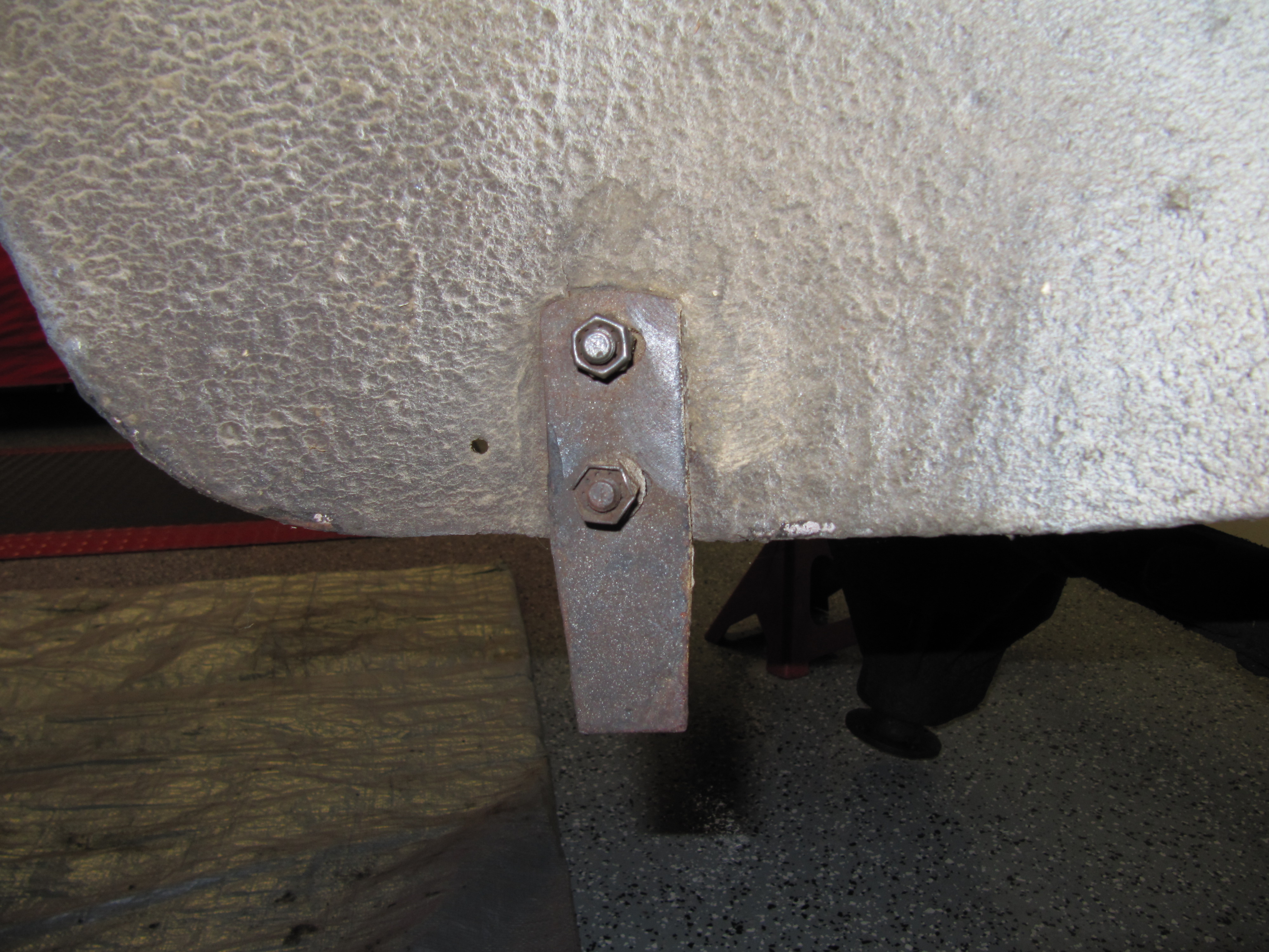
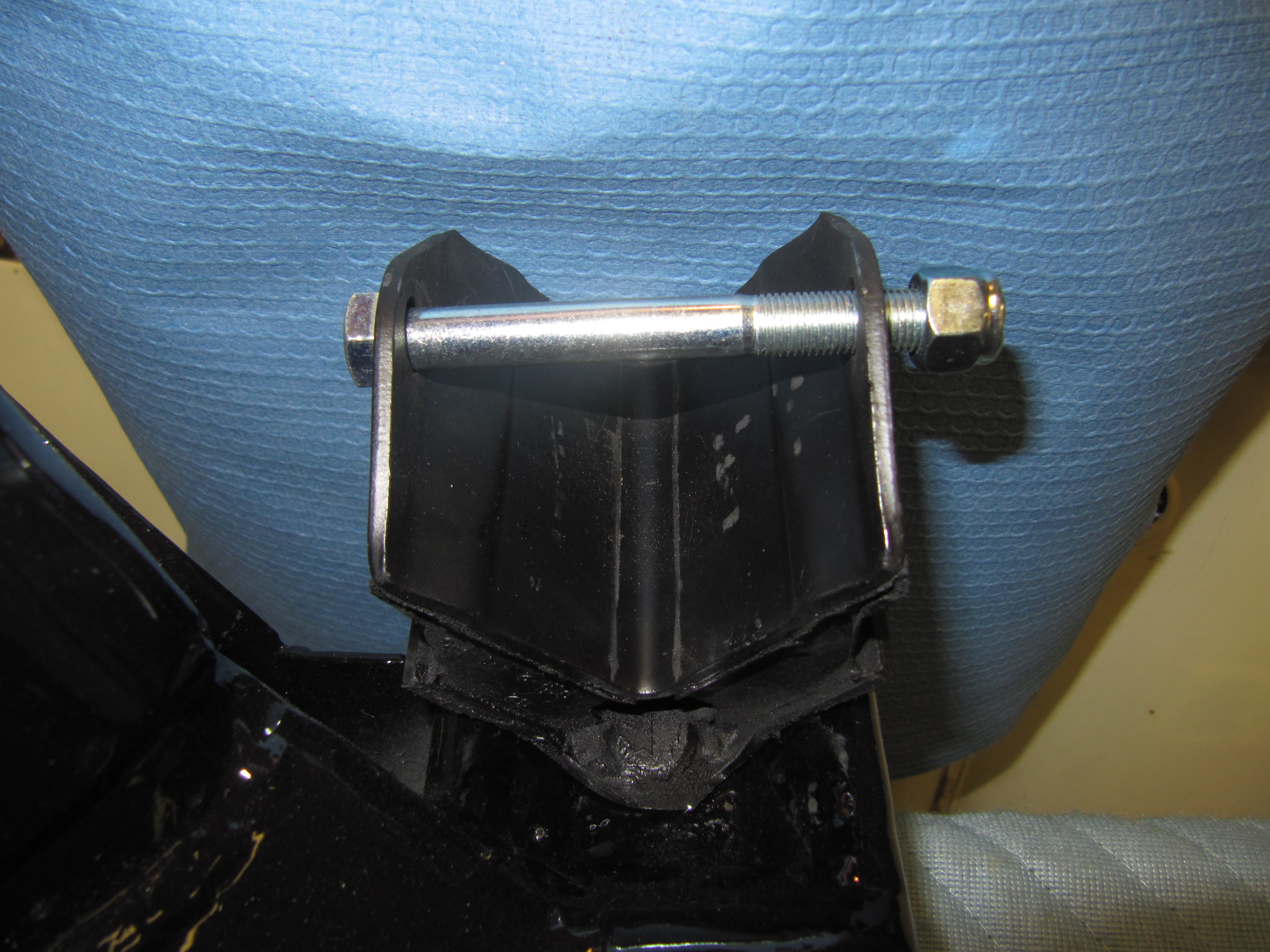
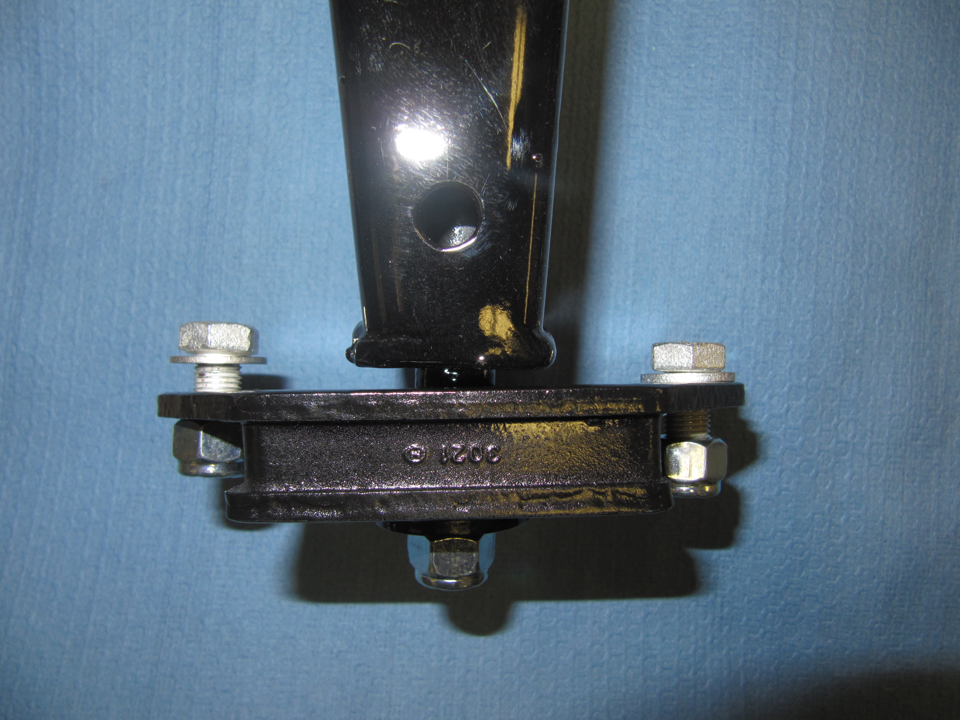
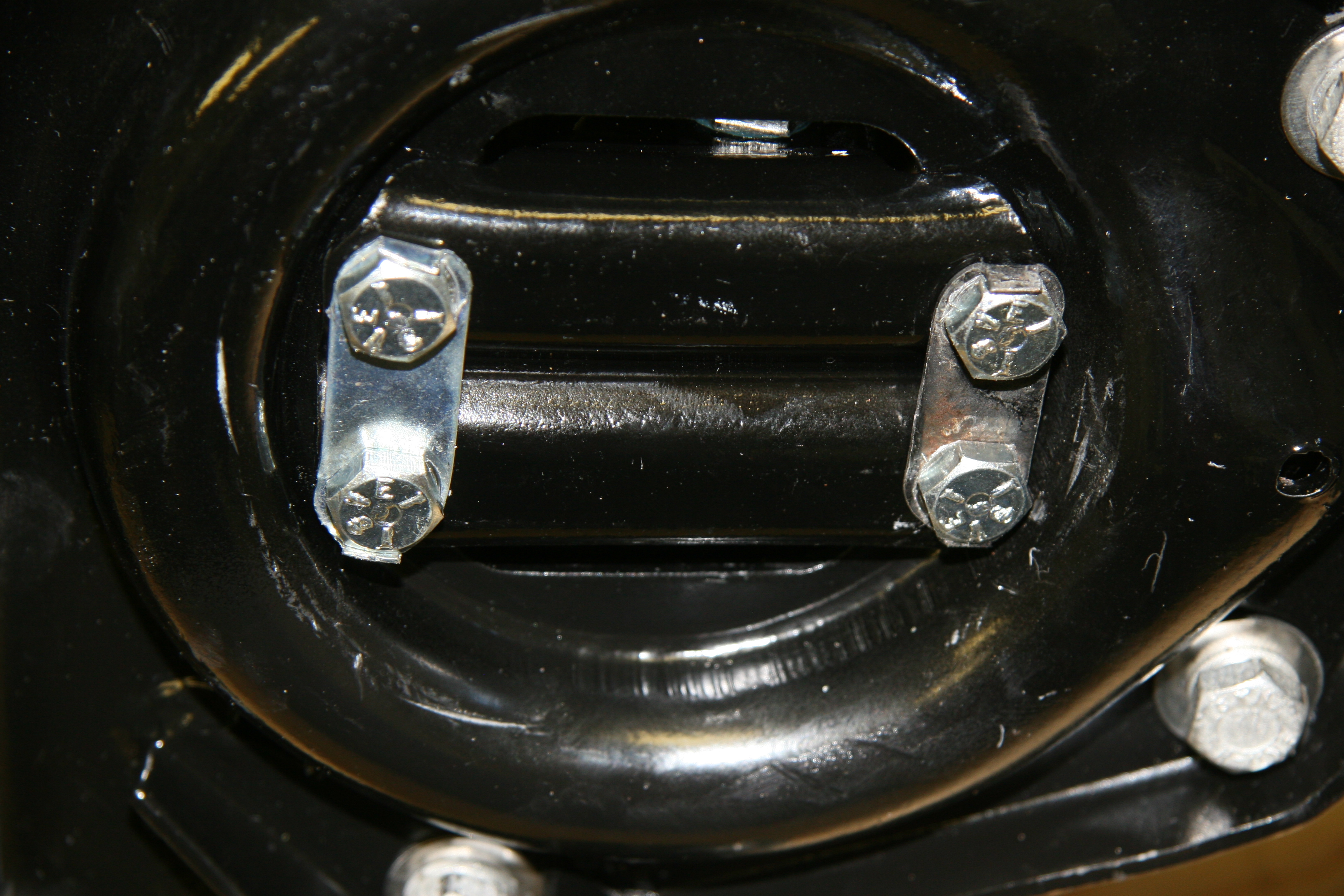
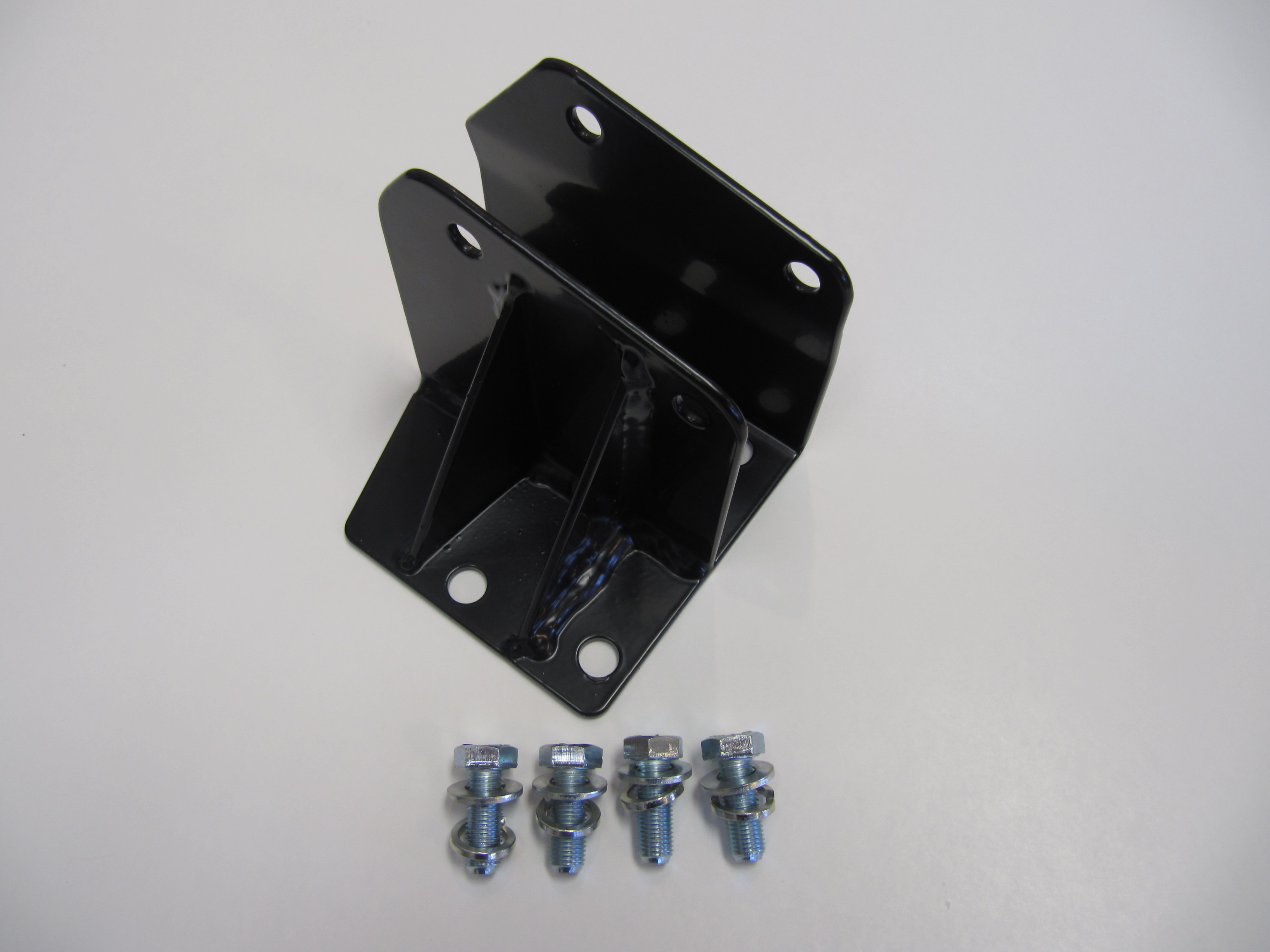
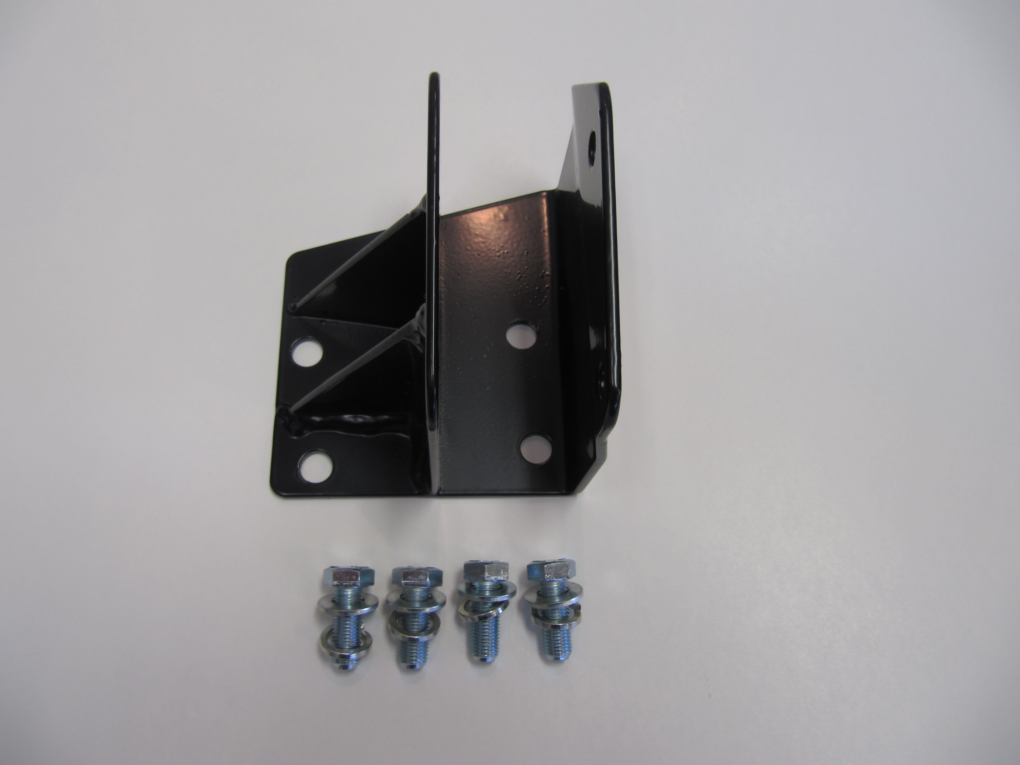
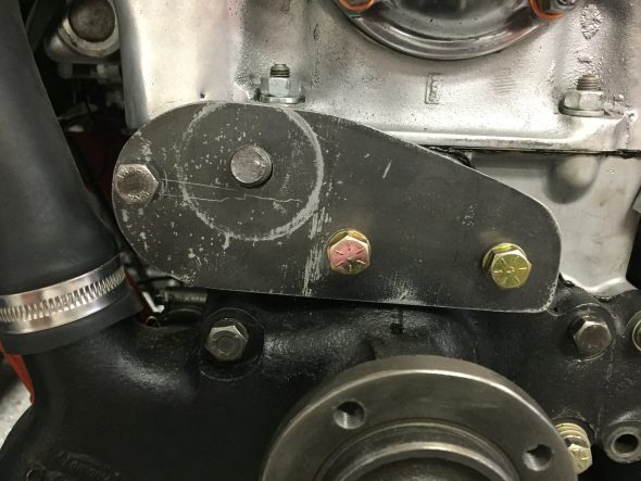
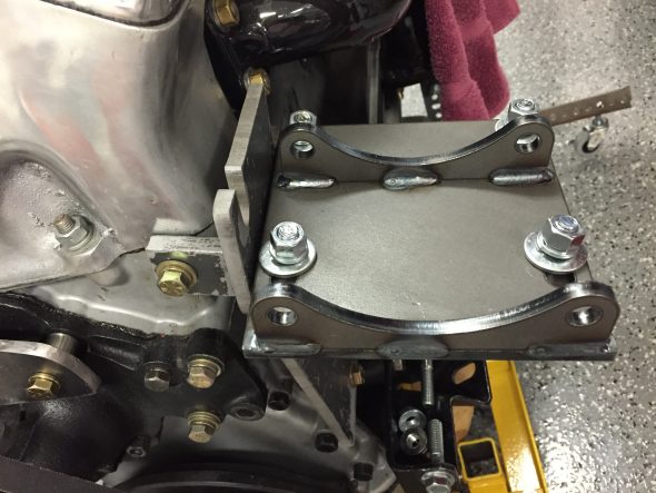
My solution, was to weld the bolts in place that fasten the York/Sanden bracket to the original York bracket as seen in the photos below:
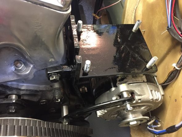
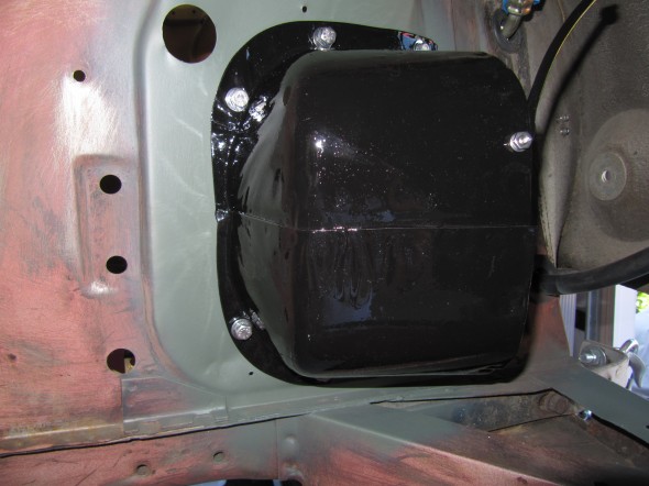
Original MK2 York Compressor Bracket with Welded Bolts for Sanden Adapter Bracket
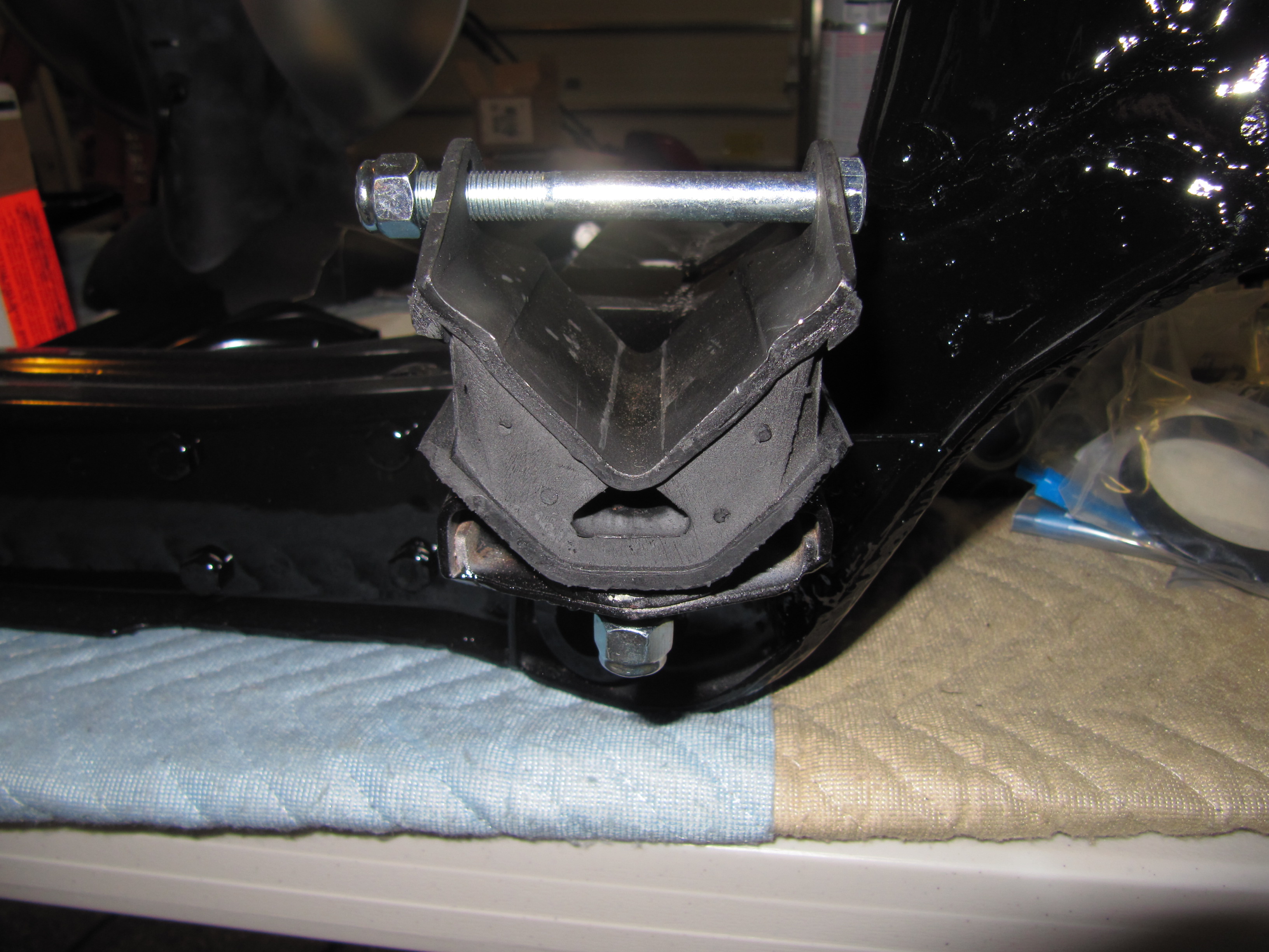
The two compressor brackets were painted with POR-15.

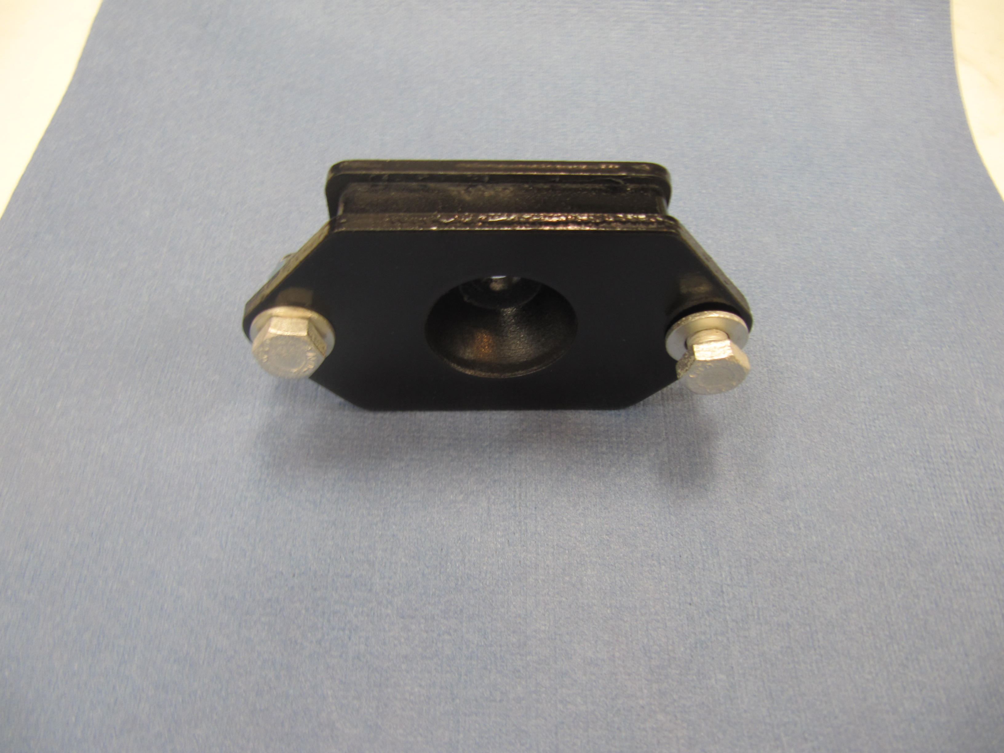
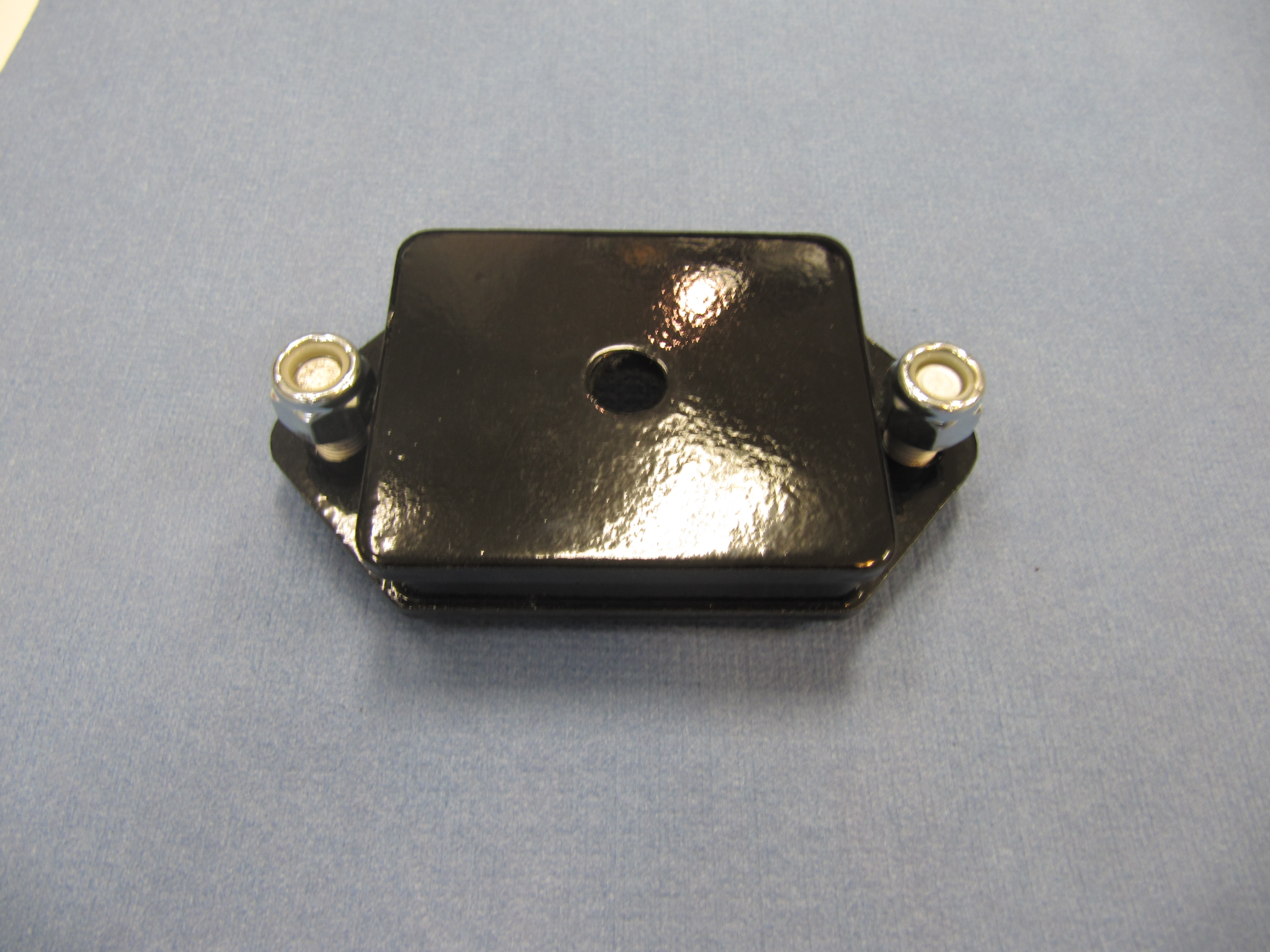
Painted original MK2 York Compressor Bracket with Welded Mounting Bolts for Sanden Adapter Bracket
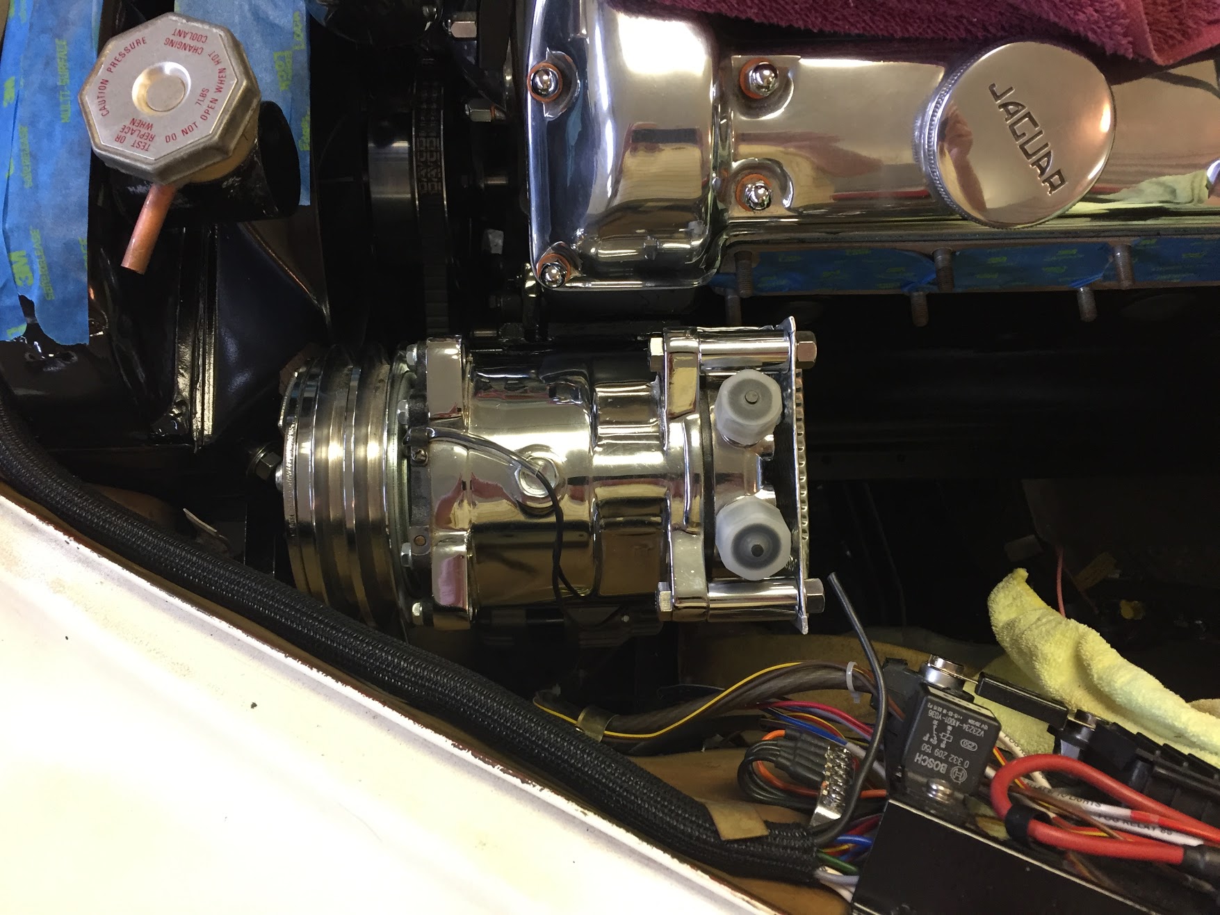
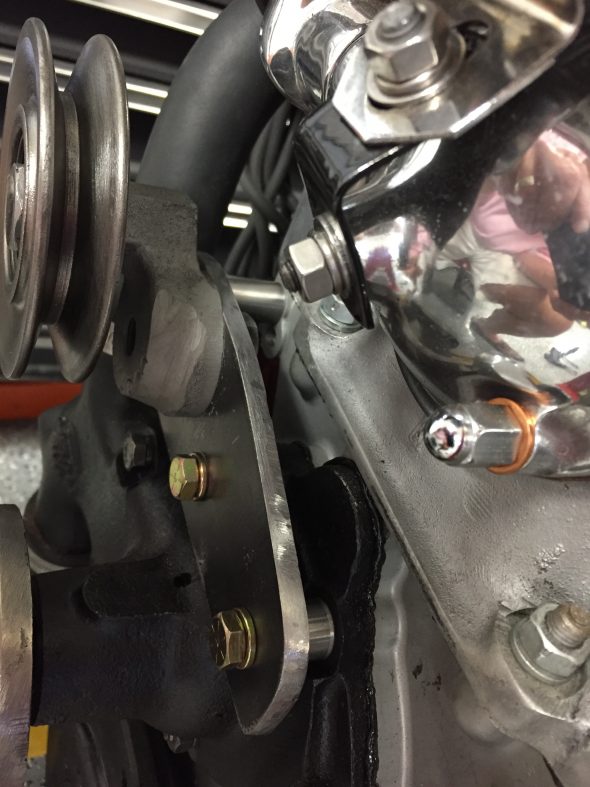
With the bolts welded to the bracket I no longer have to worry about holding the bolt head with a wrench while I tighten the nuts. This way, I am able to install the fan, modified fan shroud, and radiator and can then “drop” the compressor on its York/Sanden mounting bracket into position and tighten the securing lock washers and nuts.
Compressor on Mounting Bracket Adapter
The bolts, nuts and washers used were provided with the York/Sanden bracket and are 3/8″ – 16 coarse thread fasteners.
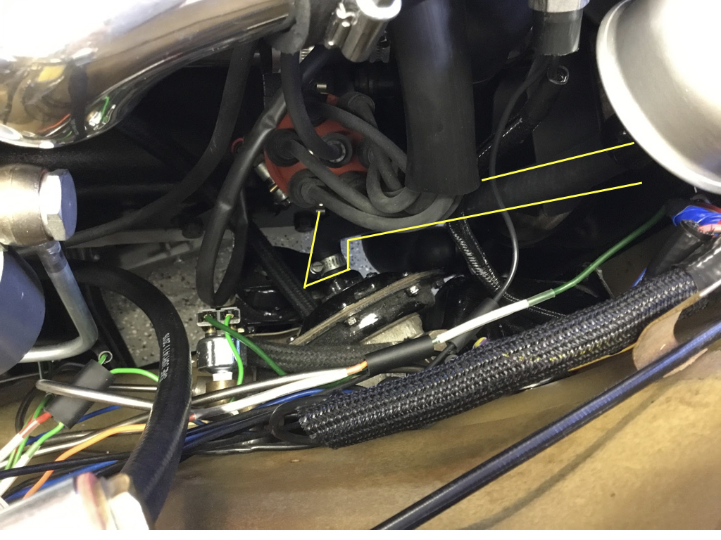
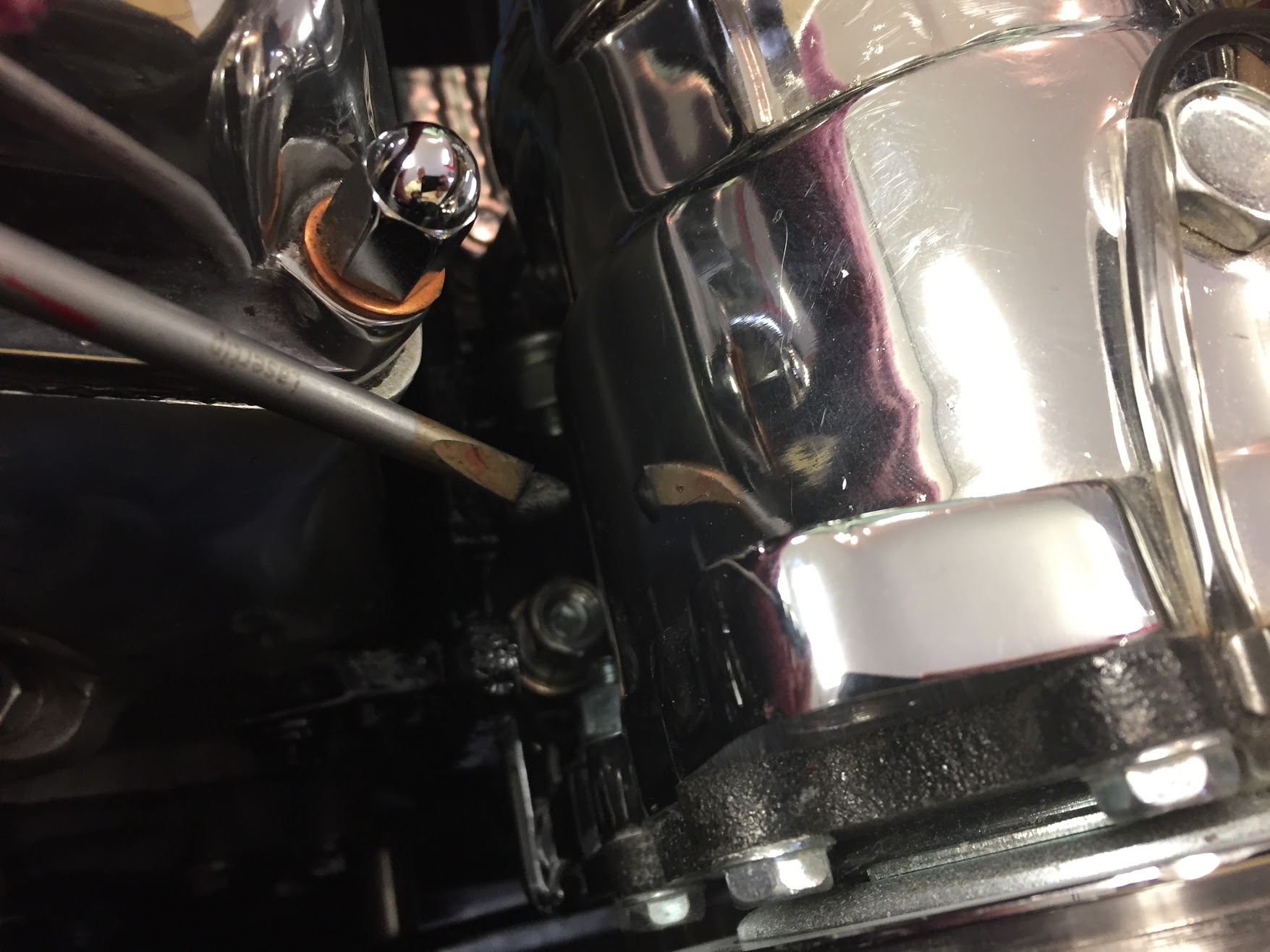
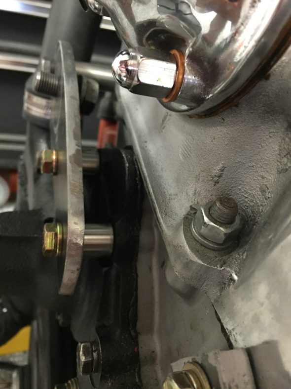
Installing the compressor with its bracket to the original York bracket is a little tricky – not hard, but it does require some fiddling. I first, set the compressor in place over the welded bolts in the York bracket. I then lifted it slightly and inserted a wrench between the two brackets to raise the compressor thereby making it easier to get the washers and nuts on the rear welded bolts. After putting the alternator heat shield in place (see narrative and images below) I could then remove the “spacer” wrench and tighten everything down. The front right bolt/nut is a challenge to access. I never did get it as tight as I might like, but the compressor isn’t going anywhere as the other three mounting points are firmly secured. This bolt/nut is pointed out with a screwdriver tip in an image below.
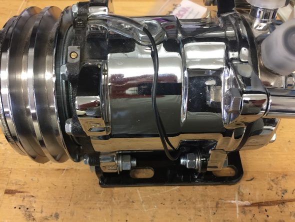
Alternator and Compressor Heat Shields
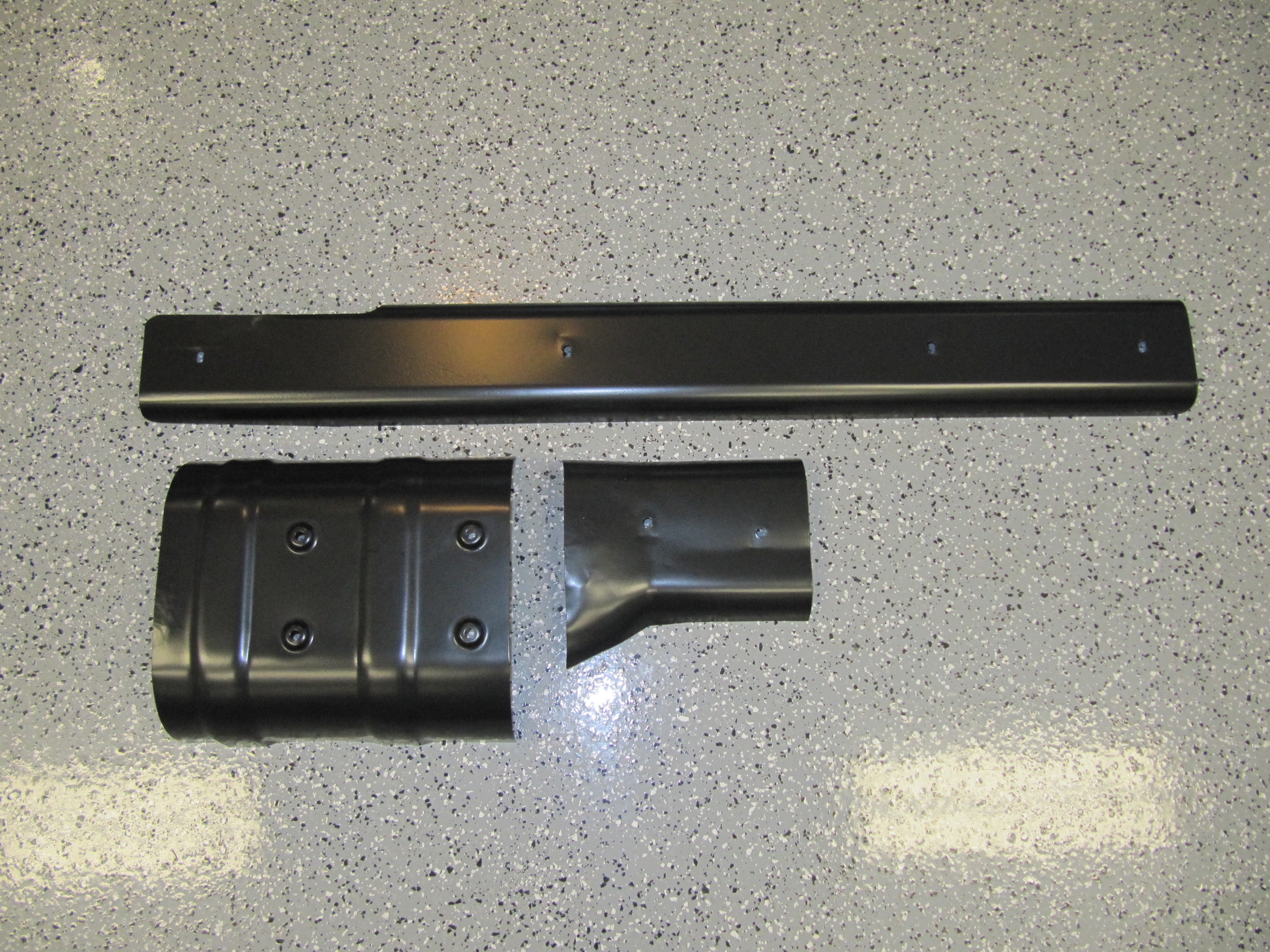
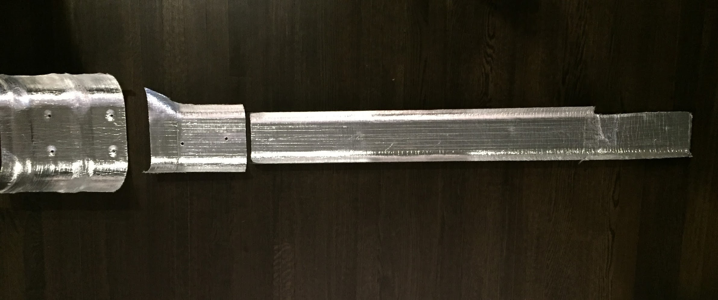
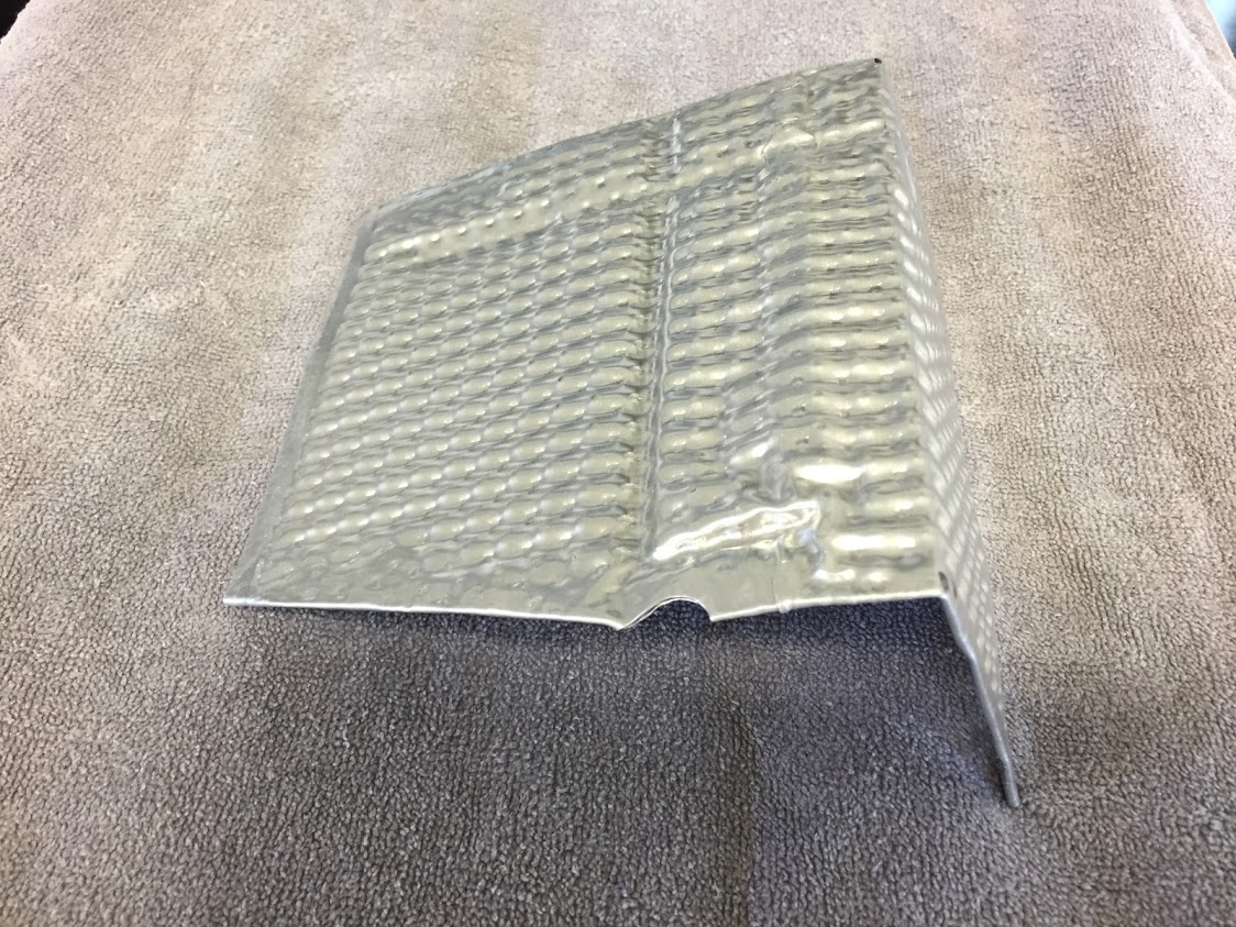
The rear of the compressor and alternator is in very close proximity to the front exhaust manifold. I fabricated aluminum heat shields to help protect both from the exhaust heat. They were cut from a panel of corrugated aluminum consisting of two sheets pressed together with internal air voids. The piece I happened to use was a Porsche product a friend gave me. I cut the shapes I needed and crimped the edges to fit. The advantage of this material is that it is pliable and can be pressed into shape while at the same time it is strong enough to be self-supporting.
The alternator heat shield is installed first.
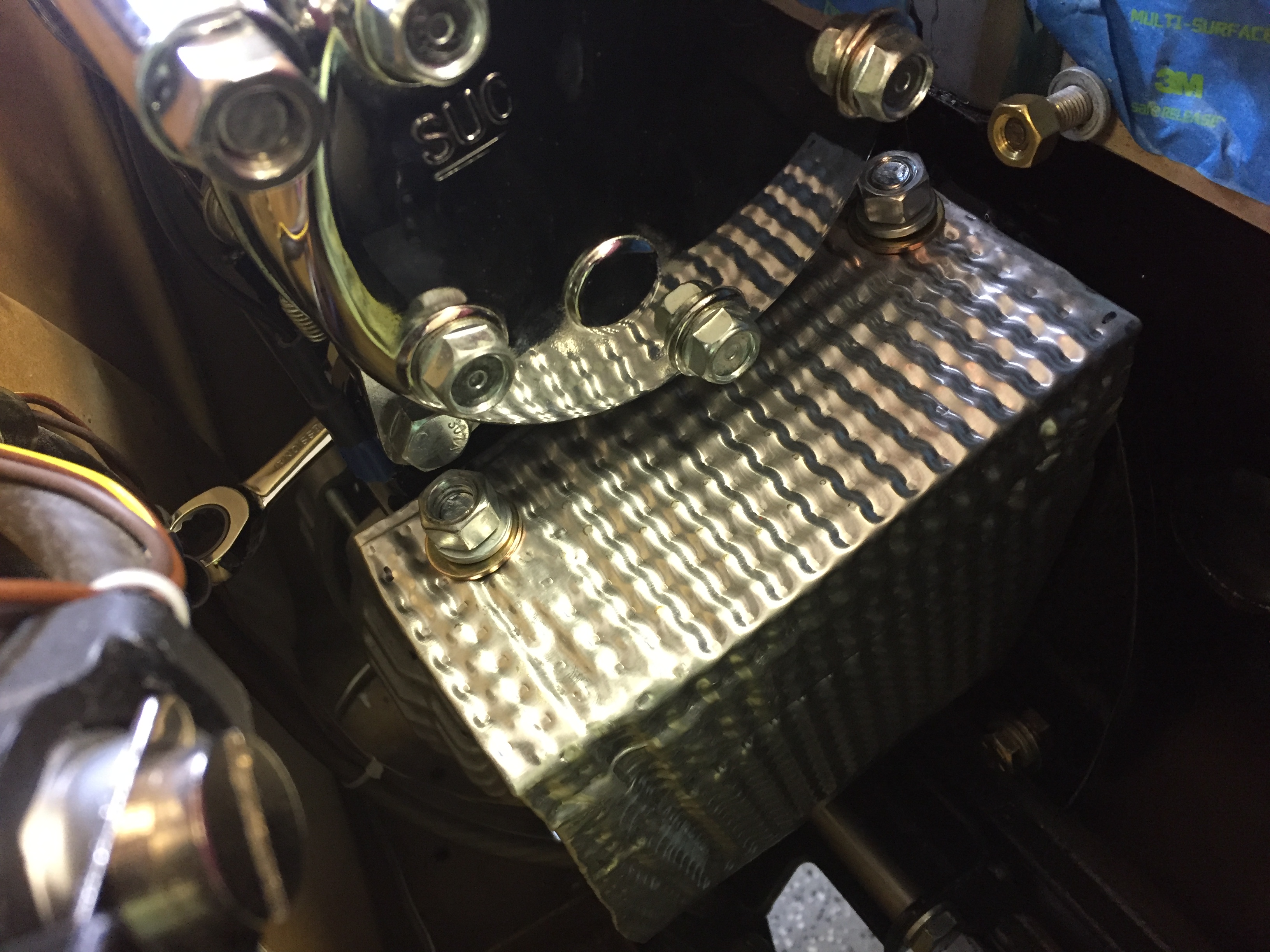
The alternator shield mounts to the two rear 3/8″ bolts that secure the York/Sanden conversion bracket to the original Jaguar-York mounting bracket. This is accomplished by setting the compressor in place over the mounting bolts, sliding the compressor fully forward and tilting it slightly forward at the front to slip the shield over the exposed bolts. The wrench in the second photo below is inserted between the two compressor brackets to raise the compressor then making it possible to place the two rear mounting nuts on the bracket bolts. After staring the nuts the wrench is pulled out and then the nuts are tightened after aligning the compressor pulley with the crank and tensioner pulley.
Alternator Heat Shield Install on Compressor Bracket Bolts

Alternator Heat Shield Installed
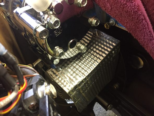
The compressor shield is mounted to the top two rear compressor mounting ears using two chrome 3/4″ OD, 1-1/2″ long spacers for 3/8″ – 24 x 2-1/2″ hex bolts and internal tooth lock washers and nuts.
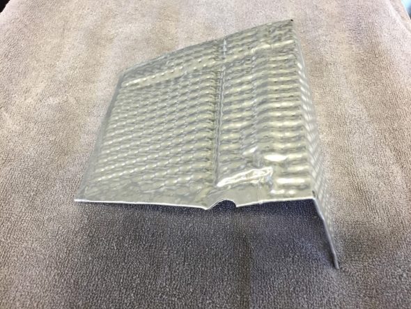
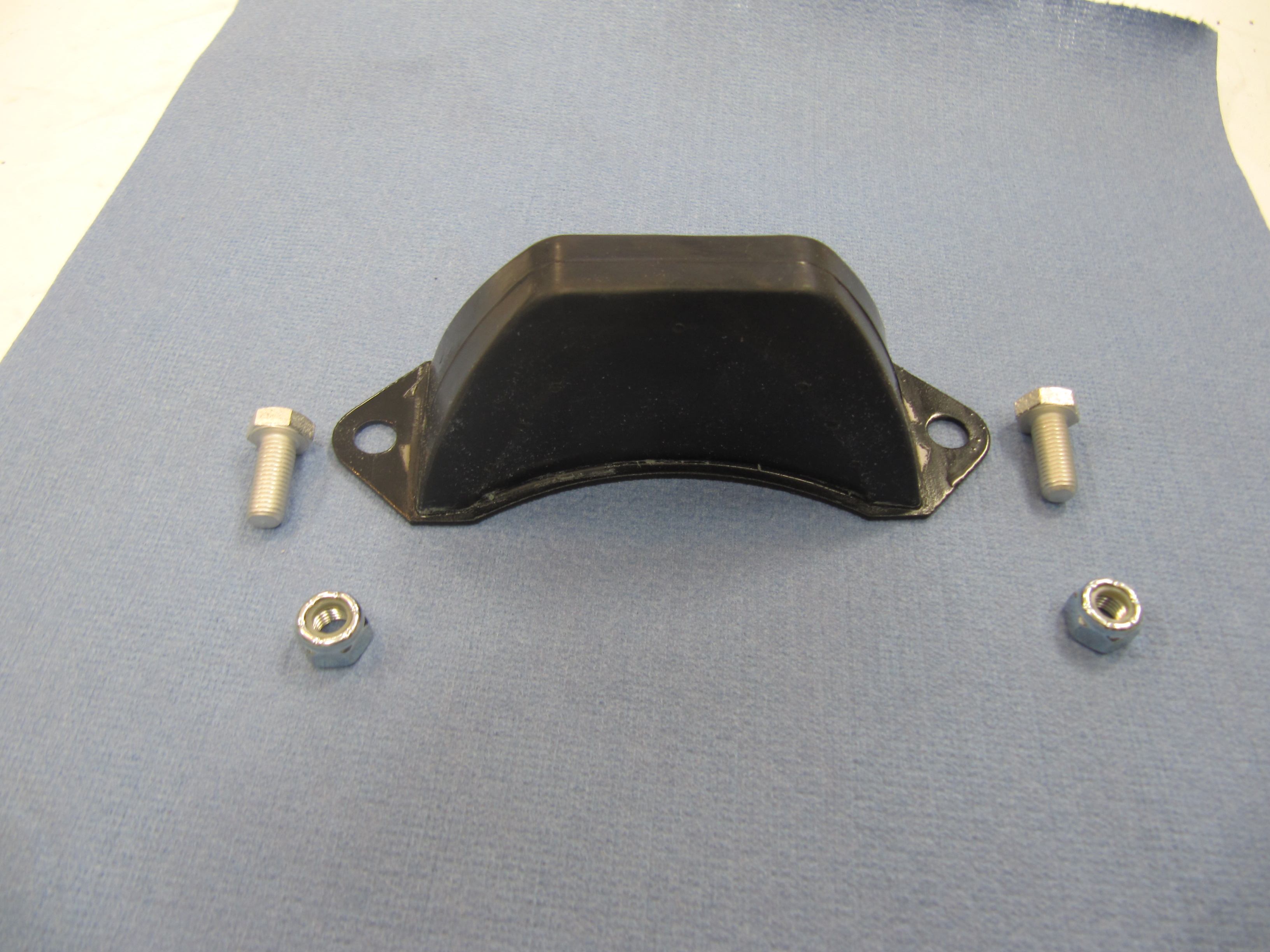
Alternator Heat Shield

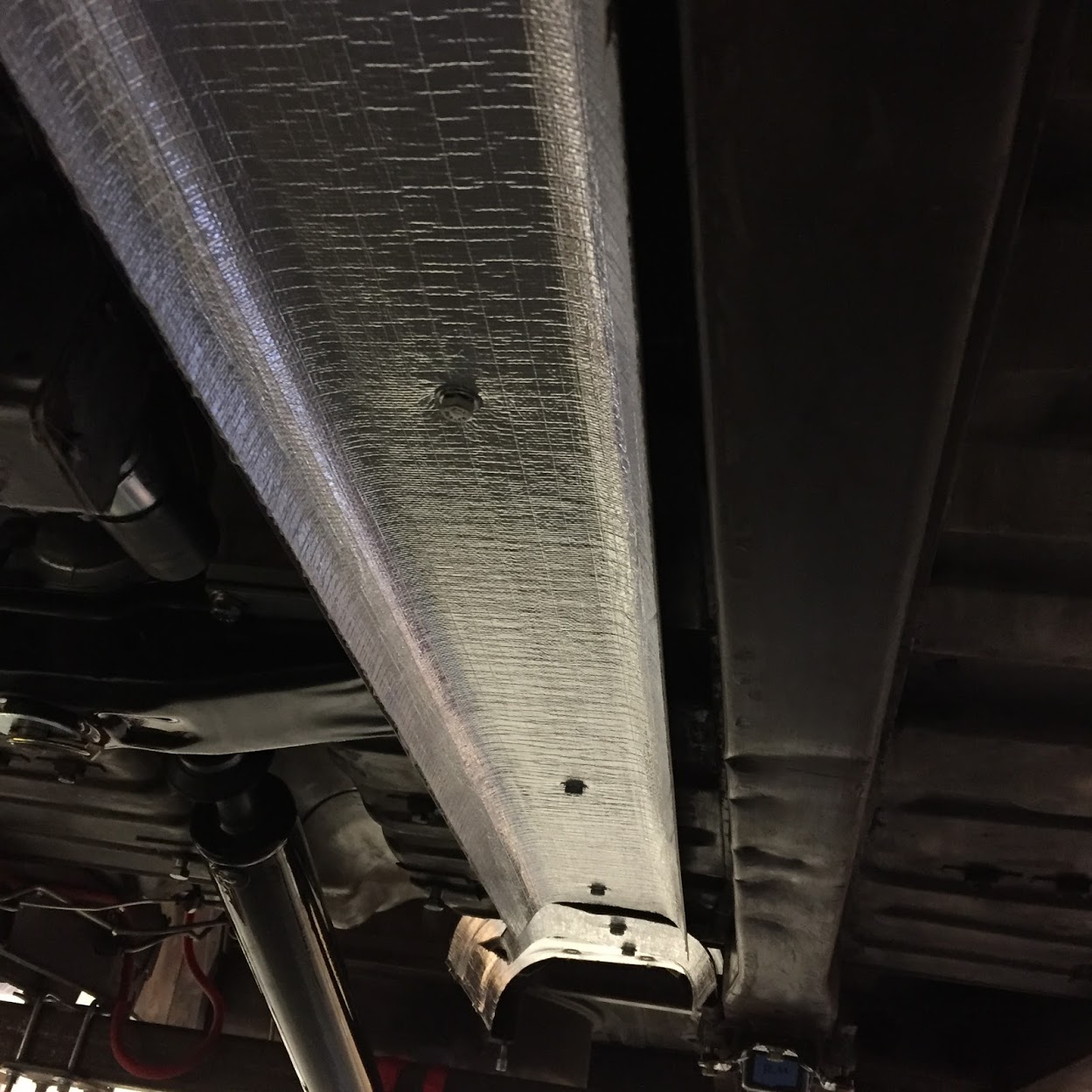
Compressor Heat Shield Mounted on Compressor Top Ears
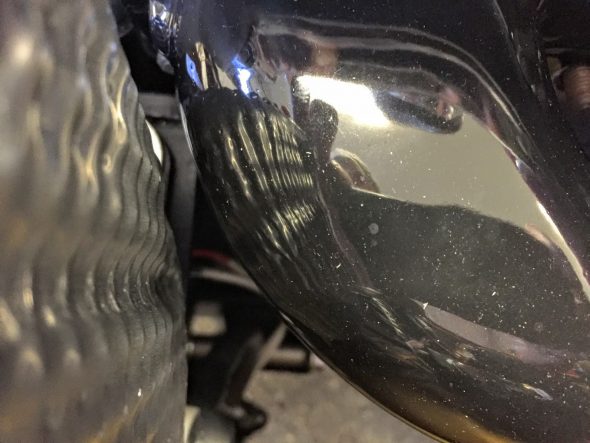
Gap Between Heat Shield and Manifold
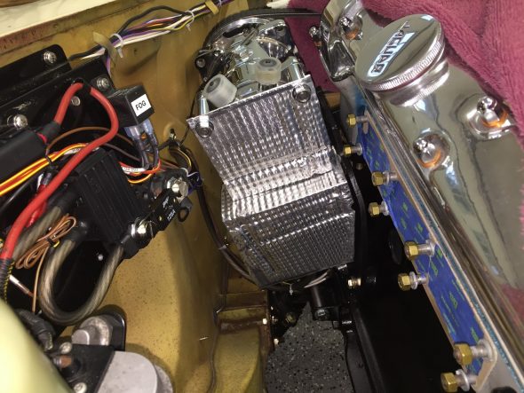
Alternator & Compressor Heat Shields in Place

Challenging Nut to Access
Pulley/Belt Circuits
So, I have covered the three pulleys on the “outside” belt circuit in my two belt system – the crank pulley, the tensioner pulley and the compressor. The compressor will use the outside groove and the tensioner pulley aligns with the compressor and the crank shaft pulley thanks to the drill bushings used as spacers. The “outside belt” I used is 1/2″ “V” belt ordered from Advance Auto Supply. I like to get expendable items like these at a common auto supply house when possible so that if the belt breaks I can easily pick up a new one. It is a DAYCO 17555 13A1410 that is 55.5″.
The “inside” belt circuit consists of the crankshaft pulley, the water pump pulley and the alternator pulley . I am using the water pump pulley provided in the RetroAir kit. It is aluminum alloy.

Water Pump Pulley
It measures 5.65″ in diameter. It is secured to the water pump with four 5/16″ – 24 x 1″ hex head bolts through the fan.
The alternator pulley is 2.6″ in diameter and was machined to fit the Hitachi alternator. It mounts to the original dynamo/motor mount bracket and is adjusted with a custom swing bracket. The swing bracket is painted black before final assembly. At the alternator, a 5/16″ID x 1/2″ drill bushing is used as a stand-off to move the swing bracket away from the alternator casing and at the bracket’s other mounting point a 5/16″ID x 7/8″ drill bushing is used as a spacer on the lower RH water pump hex head bolt. To account for the extra length of the bushing, a 5/16″ – 24 x 3-3/4″ hex head bolt is used. In the image it appears that the compressor belt is hitting the alternator pulley, but there is sufficient distance between the two.
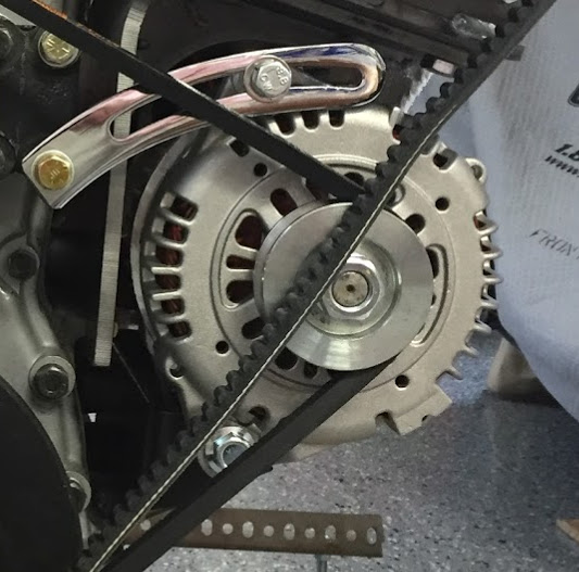
Hitachi Alternator, Pulley and Swing Bracket
It has been a long journey to this point, but that completes the components for both pulley/belt paths. The “Outside” path is tensioned with the adjustment of the tensioner pulley and the “inside” path is tensioned by adjusting the alternator on the swing bracket. This is an image of the completed system:
Completed Pulleys and Belts
The chart below provides a summary of pulley sizes and ratios along with RPMs of each pulley when the crankshaft pulley is turning 1,000 RPM:
| Accessory |
Pulley Diameter |
RPM |
| Crank |
5.83” |
1,000 |
| Alternator |
2.61” |
2234 |
| Water Pump |
5.66” |
1030 |
| Compressor |
5.197” |
1122 |
Motor Fan
The cooling fan for the motor is addressed in the Cooling Post. I am using a modified fan sourced from Guy Broad Jaguar in the UK.
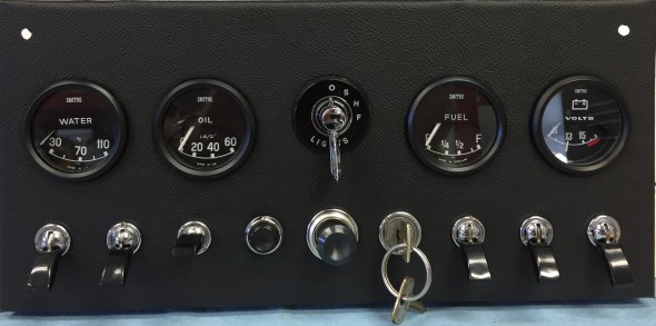
Controls and Electrical Connections
The wiring of the air conditioning system in my Jaguar MK2 is described more fully in the “Building a Wiring Harness” Post. The components in the electrical wiring include: the compressor, the trinary pressure safety switch, the radiator fan, the blower, the radiator fan manual override toggle switch, the coolant temperature sensor switch at the radiator, and the fused power source. Plus the operating controls consisting of two rotary switches, one for the blower fan speeds and the other for the adjustment of air temperature.
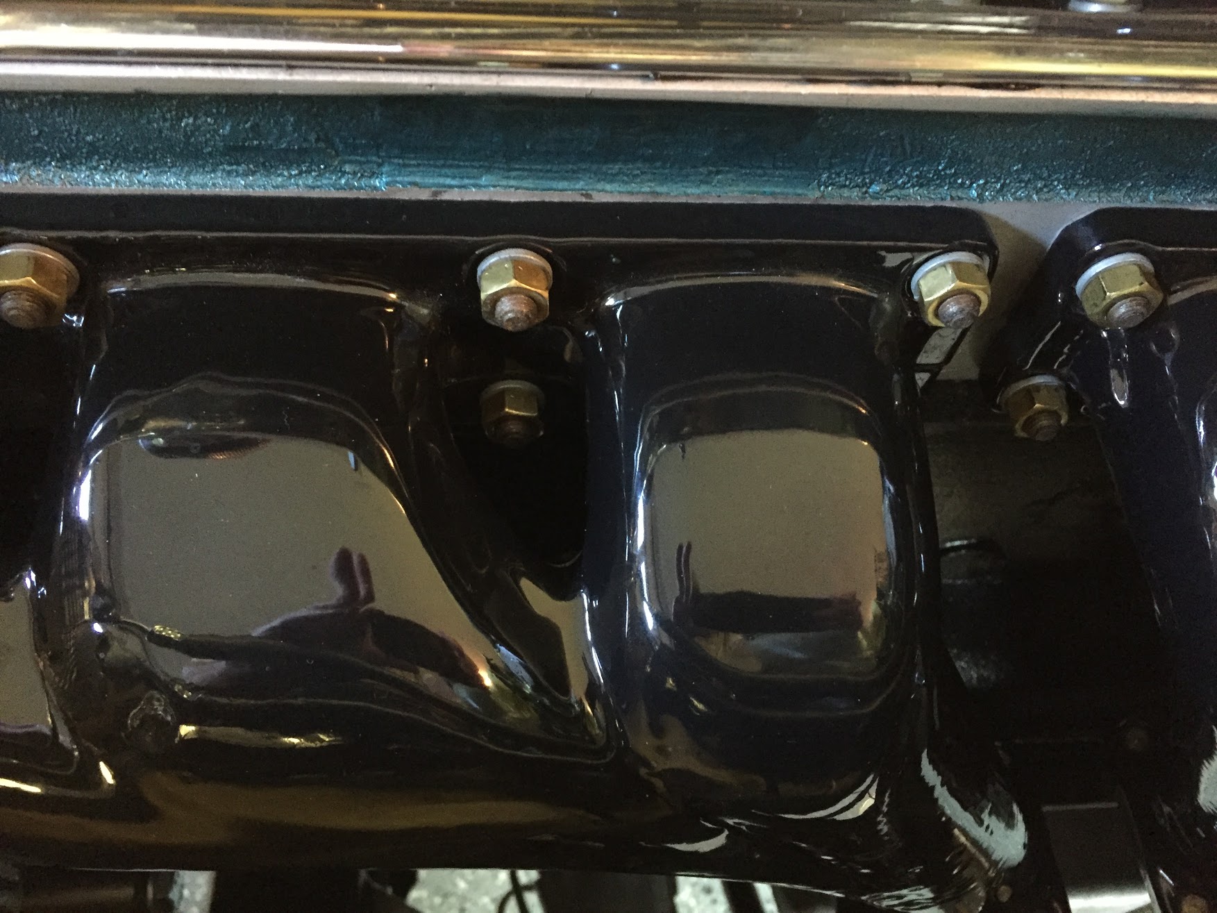
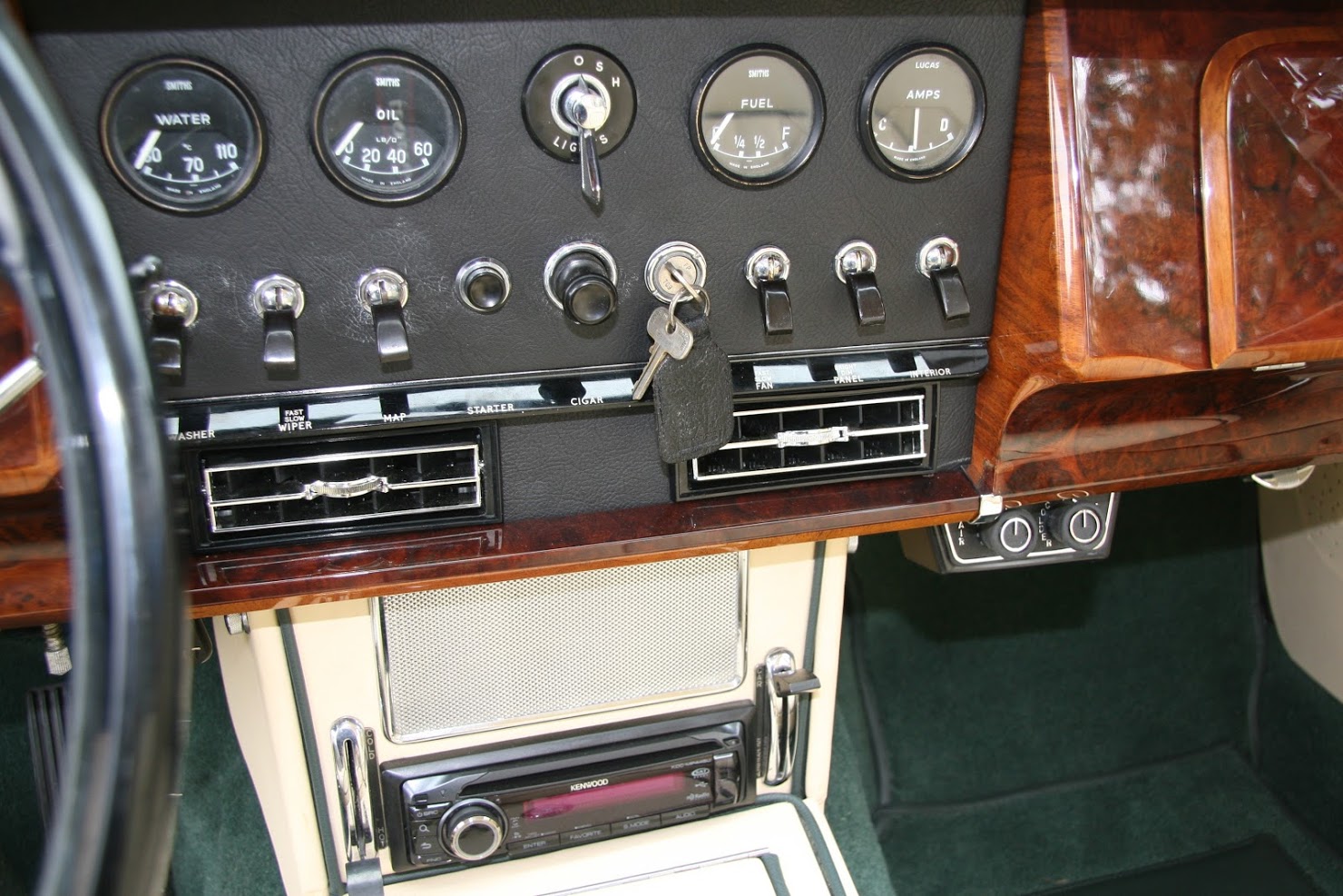
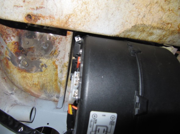
I have only seen a few cars with the RetroAir kits installed. The ones I have seen typically have the thermostat switch and the blower switch mounted in a plastic housing below the dash on the passenger side of the car. The housing is provided in the RetroAir kit. The photo below shows a typical installation:

Air Conditioning Controls Below the Dash
The kit installation looks nice and certainly fits with the central gauge panel theme, but I wasn’t keen on using a plastic housing for the controls and I wanted a more stealth appearance. I was motivated by a photo of a J.D. Classics MK2 that apparently had an integrated heating/cooling system.
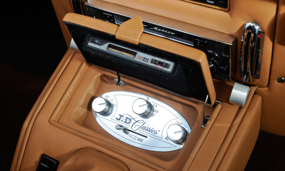
J.D. Classic Air Conditioning/ Heating Controls
So I too decided to mount the switches where the console ash tray is mounted. This turned into a big job that took quite a long time because fitment was all by trial and error. I will not claim that what I ended up doing is the proper way to attack this issue, but it produced the desired effect.
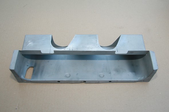
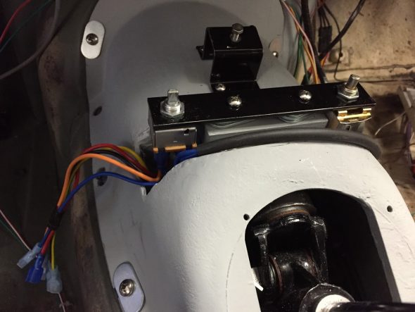
The challenge is that the two control switches have to be mounted low enough to avoid the knobs contacting the ash tray lid. As can be seen in the images below, this required cutting and modifying the gearbox cover.
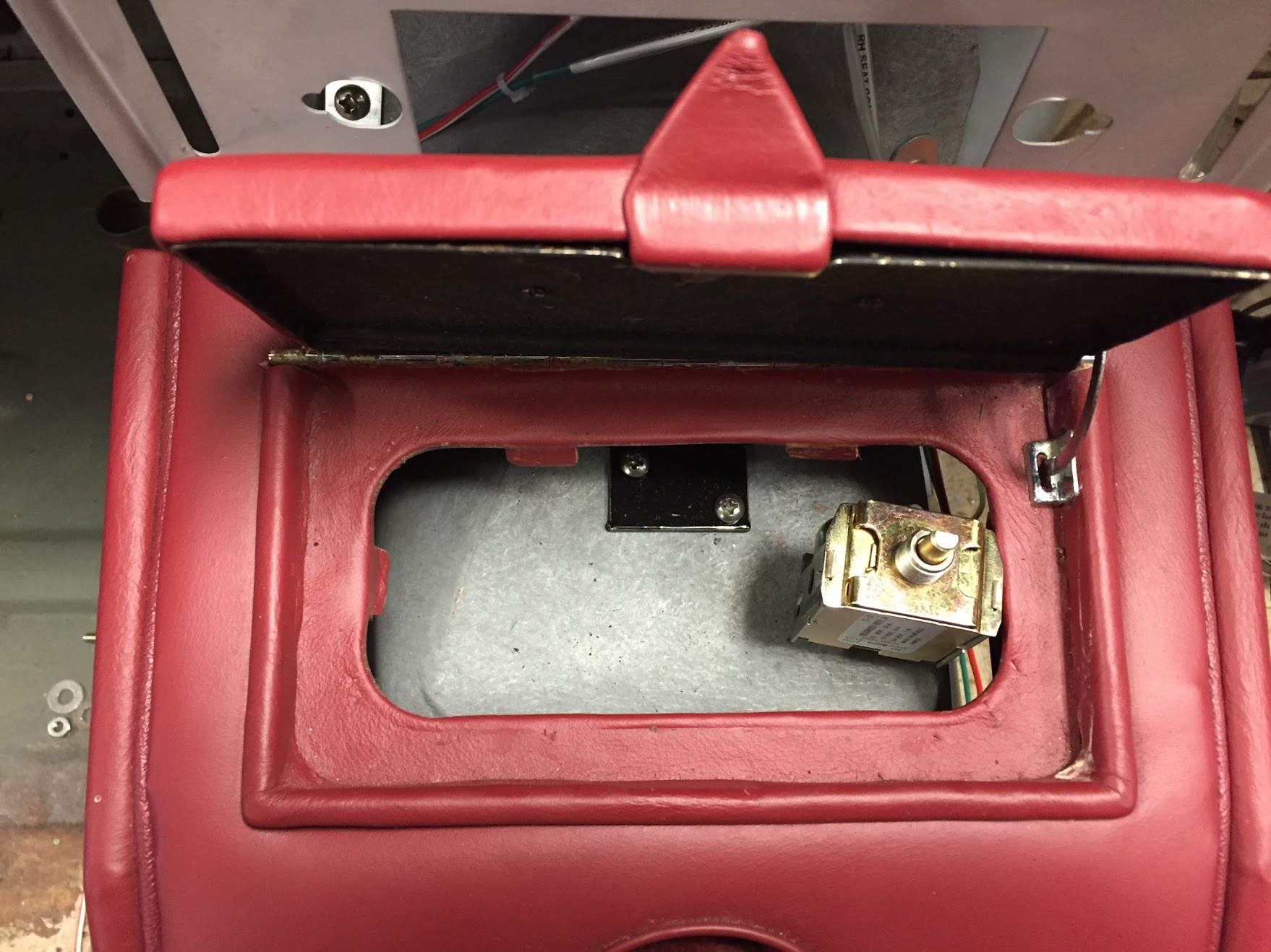
Location of Air Conditioner Control Switches
Location of Air Conditioner Control Switches
The switches need to be moved to the outside of the ashtray opening to clear the gearbox, but there is room on each side to make things work. One also needs to account for the wiring terminals and wiring that exits the bottom of both switches.
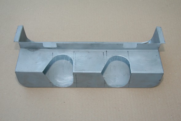
I created fiberglass”pockets” on each side of the gearbox cover so that the switches would be sealed from the elements and to keep heat and fumes from the gearbox entering the interior of the car. I am inexperienced in these things so cutting the openings to fit (the switches are not the same size) was a bit tricky and I am embarrassed by my fiberglass work, but all of this is hidden by the console.
Modified Gearbox Cover for Air Conditioning Switches
Underside of Modified Gearbox Cover with Closed Cell Foam Gasket
I decided that it was best to mount the switches to the gearbox cover rather than to the ash tray assembly. This allows one to complete the wiring before the console is mounted which turns out to be much easier than the alternative. I glued a wood block to the center of the gearbox cover between the switch “pockets” to which I mounted a steel strip with openings drilled for the the switches and for two stainless #10 – 1″ screws. I intentionally made the block a little lower than what was ultimately needed, electing to then use shims to get the proper height for the ash tray mounting – easier to see in a photo than to describe:
Air Conditioning Switches Mounted to Gearbox Cover
I then cut a flat piece of aluminum sheet to fit inside the ash tray assembly and drilled holes for the switches. After installing this cover plate I pushed the rubber switch knobs onto their stems and I have my stealth air conditioning controls!
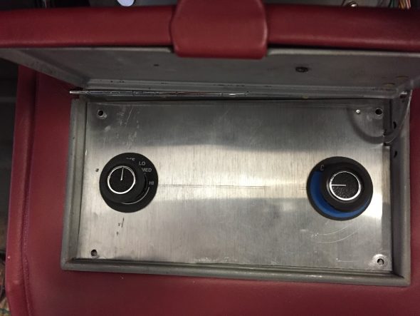
Aluminum Cover Panel for Air Conditioning Controls
I will cover the aluminum sheet with leather matching the interior. The Vintage Air supplied graphic knob surrounds are really too small in this application. As you can see, the fan control wording is hidden by the knob. I will have a trophy shop engraver make some polished engraved plates to surround each knob as seen in roughed-out fashion below:
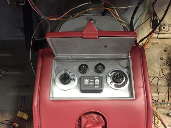
Air Conditioning, Cruise Control, Radiator Fan, and Heat Evacuation Blower Switches
Getting closer to a finished product, I have added two small rocker switches and the cruise control module to the space formerly occupied by the ash tray that I would have never used. I think that once this is all covered in leather and I have proper knob surround plates this will look quite handsome – but as always, that is just my opinion!