Wiring to the rear of the car

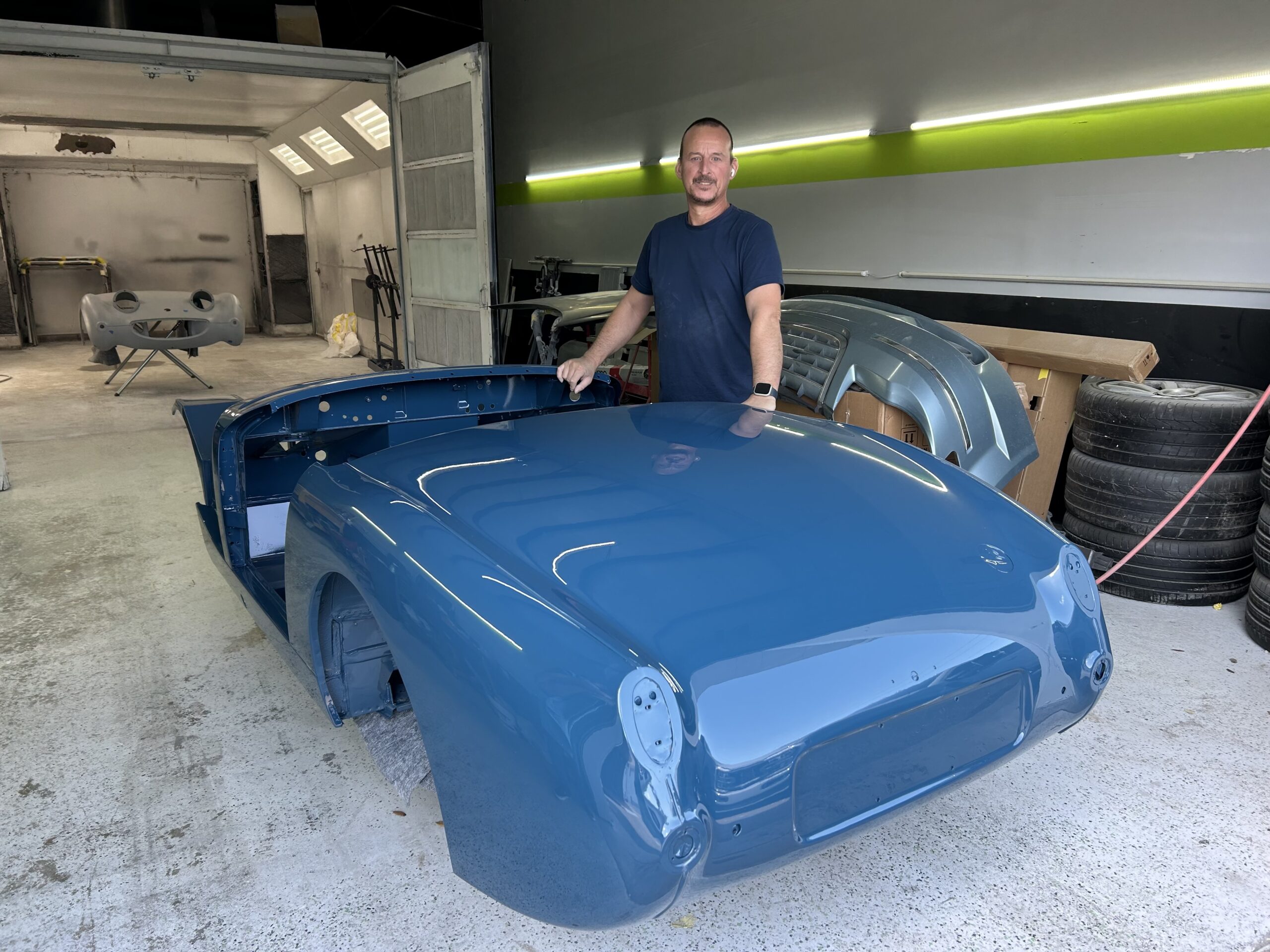
We completed the wiring harness for the central part of the car and to the bonnet before the Bugeye went for paint. Now that the car is home we are able to finish up the wiring to the rear so that we can send the harness components off to Rhode Island Wiring to have them wrap the harnesses in cloth braid.

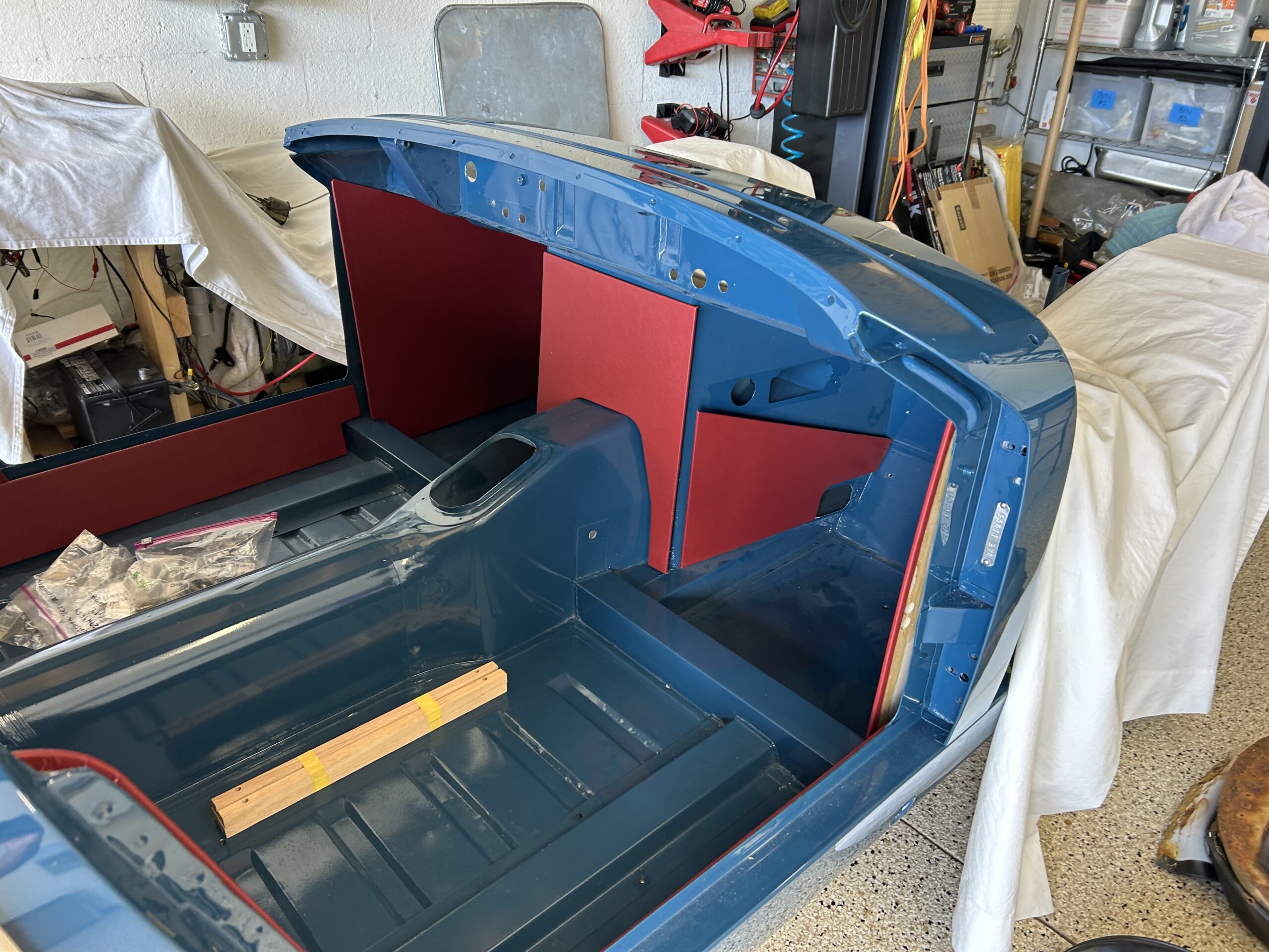
Crawling into the inside rear of a Bugeye, or “hole” as I refer to it, is no easy task. It is best handled by a nimble young contortionist – not by a 6′ 1″ seventy-two year old! Wiring the tail lights with brake lights, flashers and side lights, the license plate lamp, the fuel level sender, the fuel pumps and rear courtesy lights required many a trip into the depths of the “hole.”

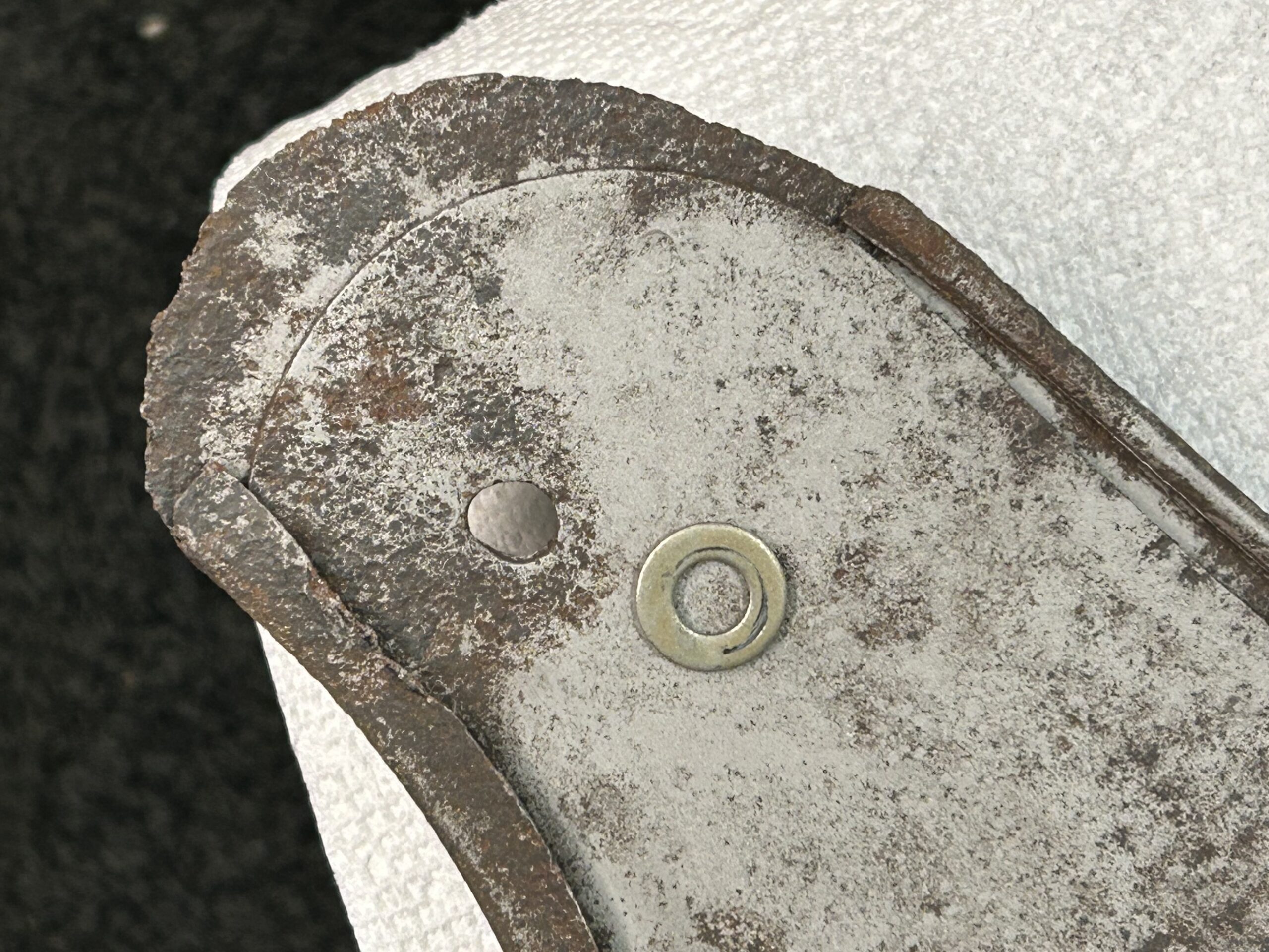
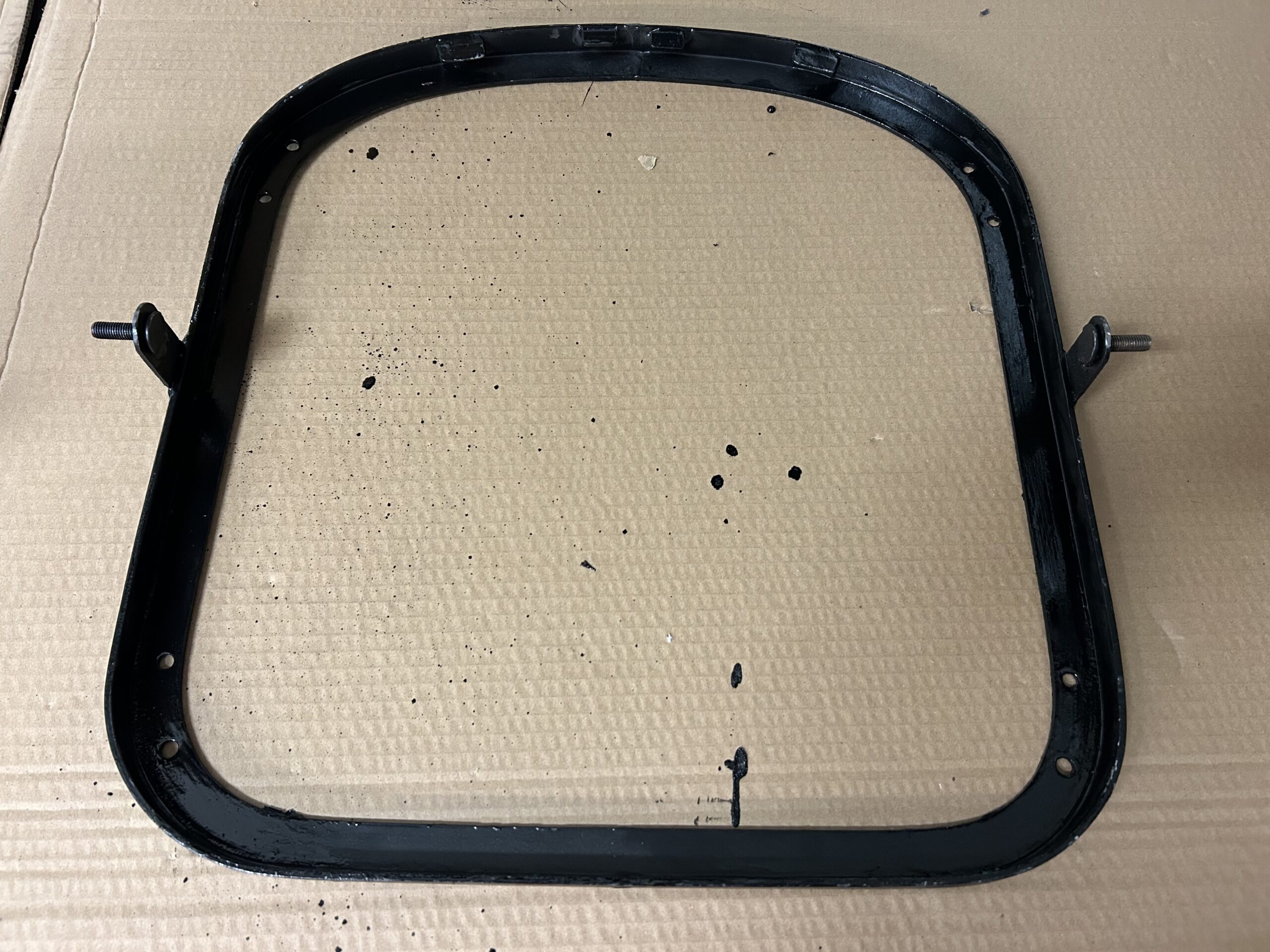
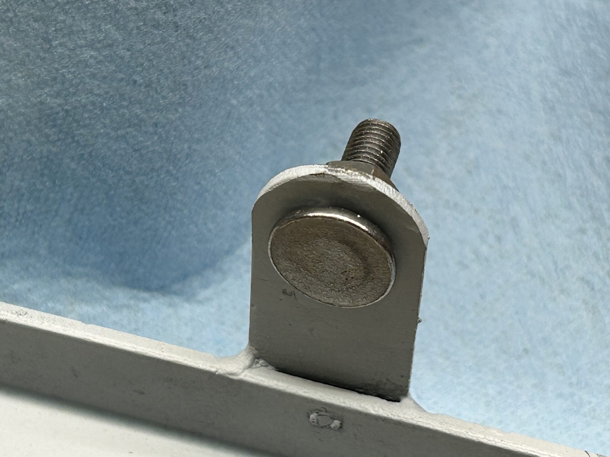
The rear flashers require the installation of spire nuts to the body. We purchased some new ones and mounted them.

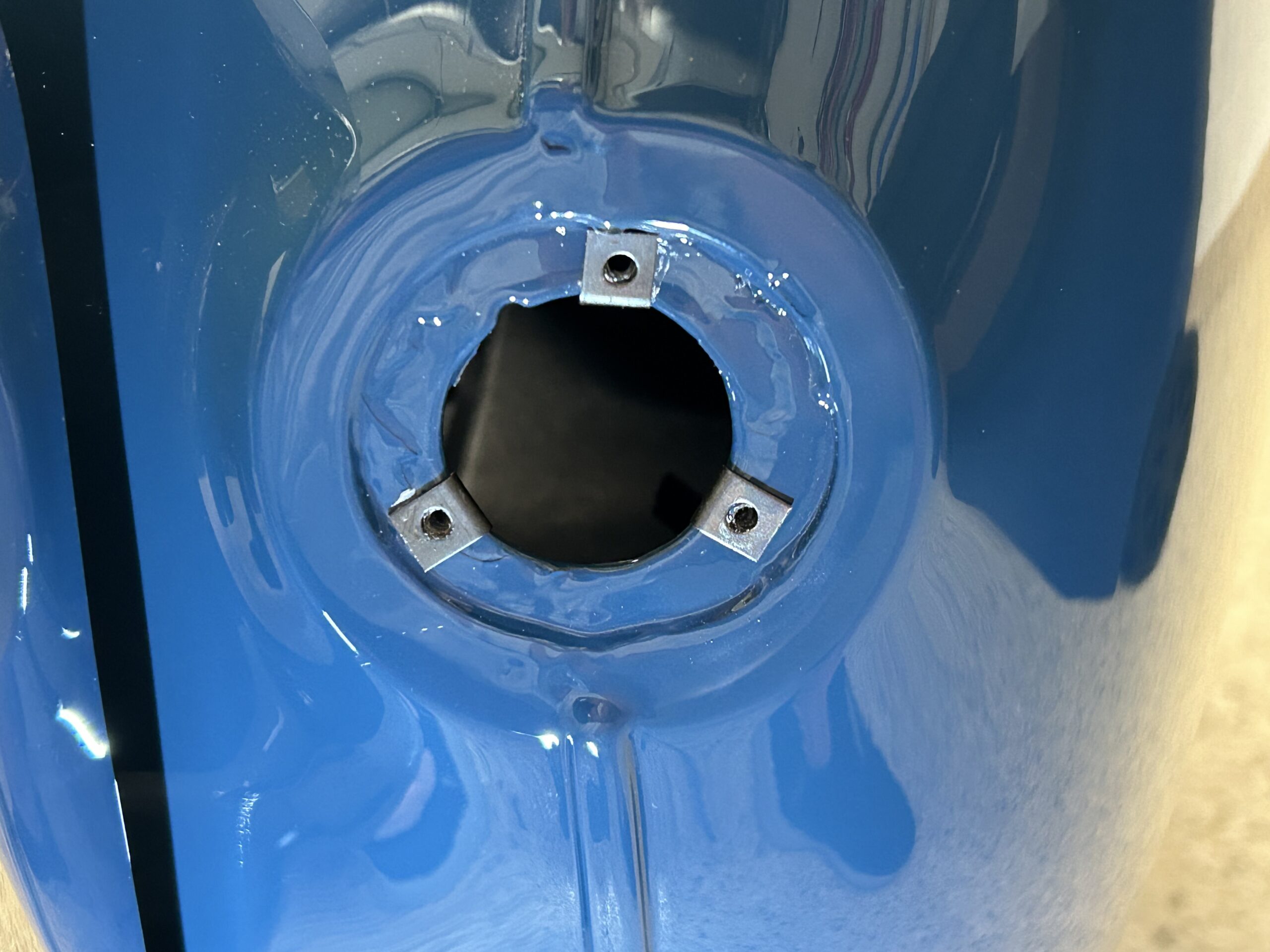
Rear Flashers Spire Nuts

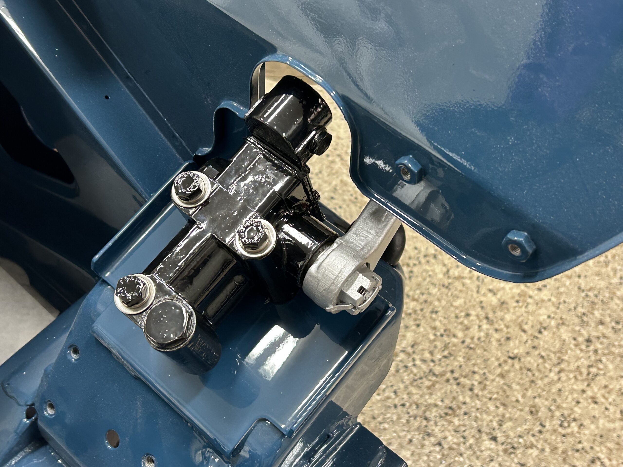
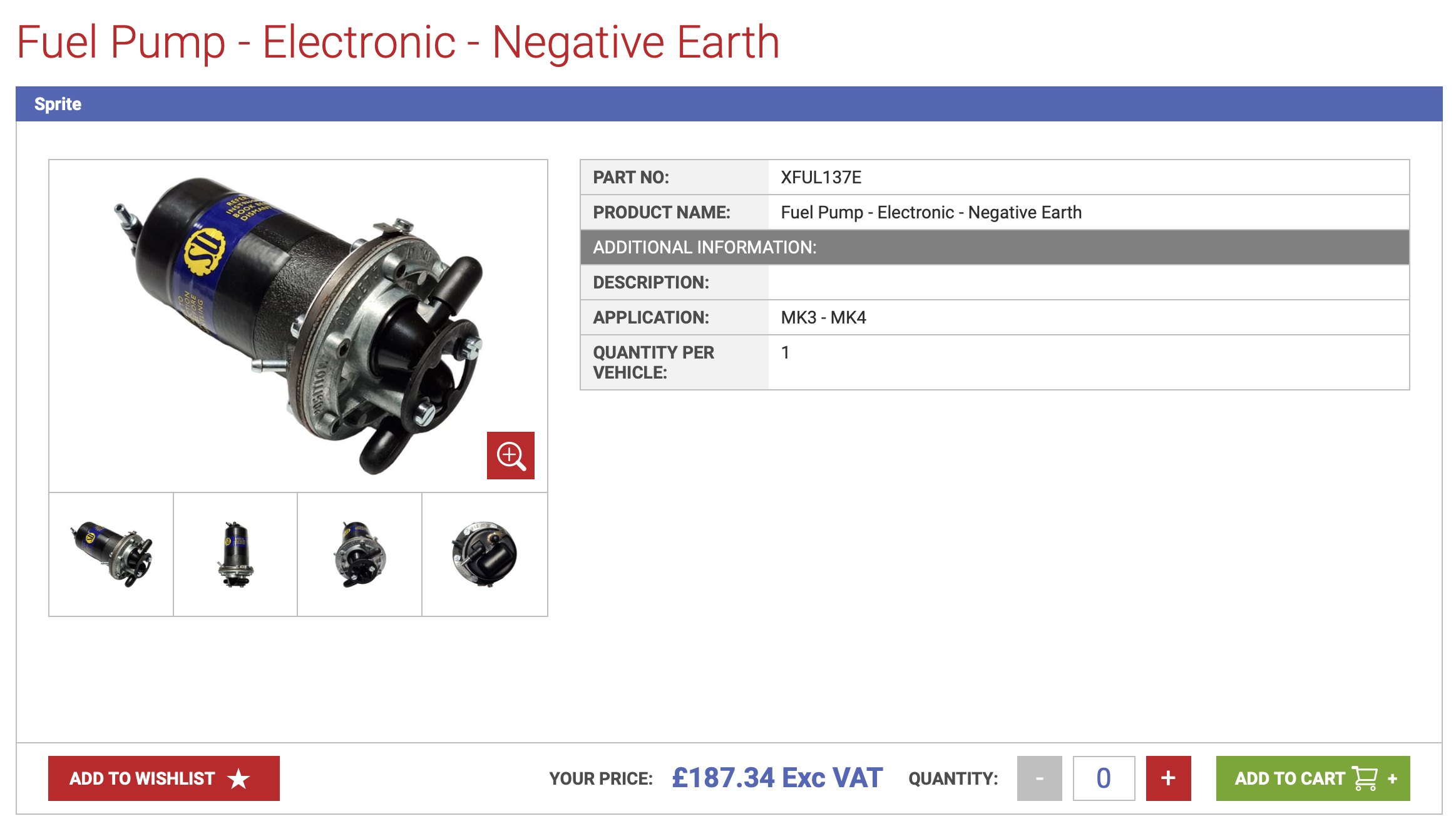
The original Sprite MK I had a mechanical fuel pump but with the onset of later Sprites, and the 1275 engine, the design was modified to incorporate a rear mounted electric pump. In our case, we mounted the SU pump as it would have been secured in the later Sprites, but we also added in series a redundant low-pressure Facet pump with a dash mounted switch enabling the driver to switch between the two pumps as desired. The center position on the switch disconnects power to both pumps providing a form of anti-theft deterrent.

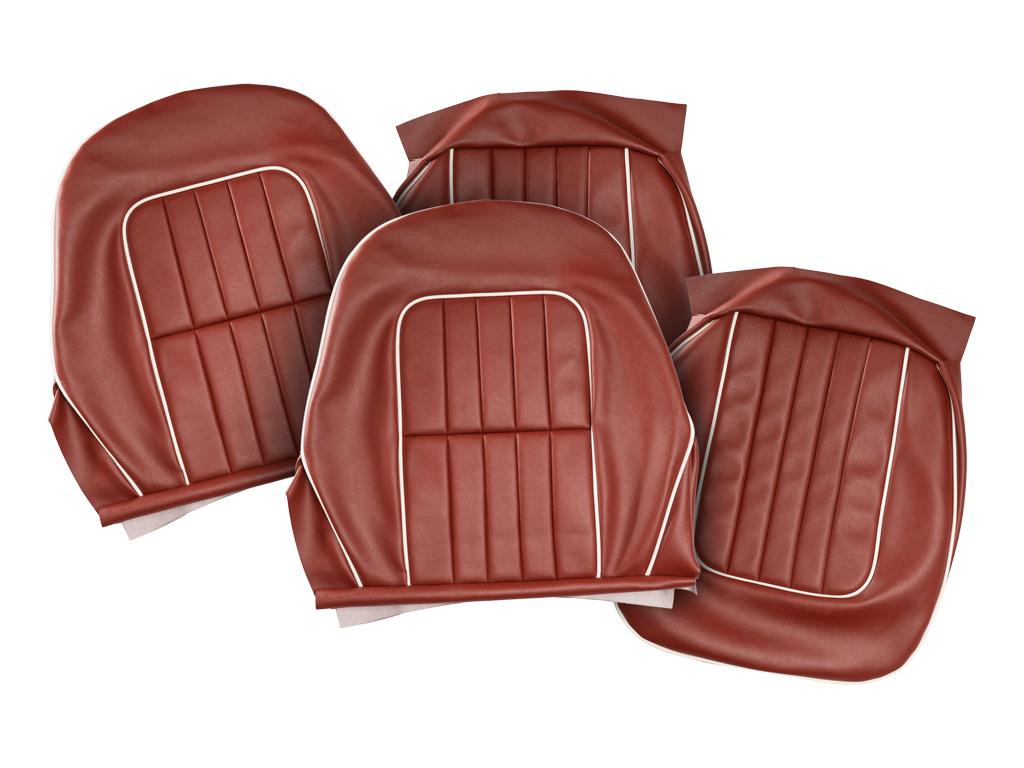
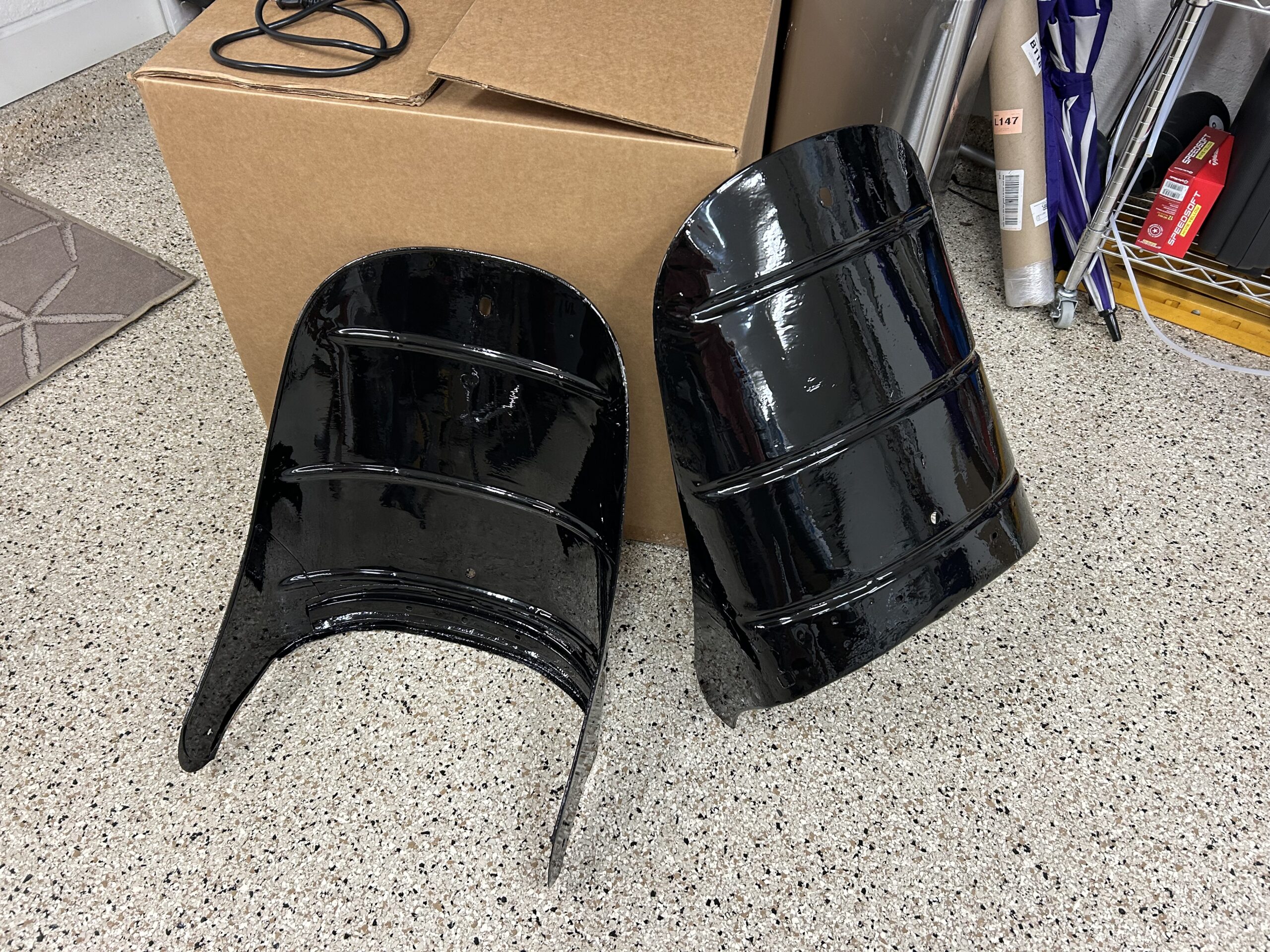
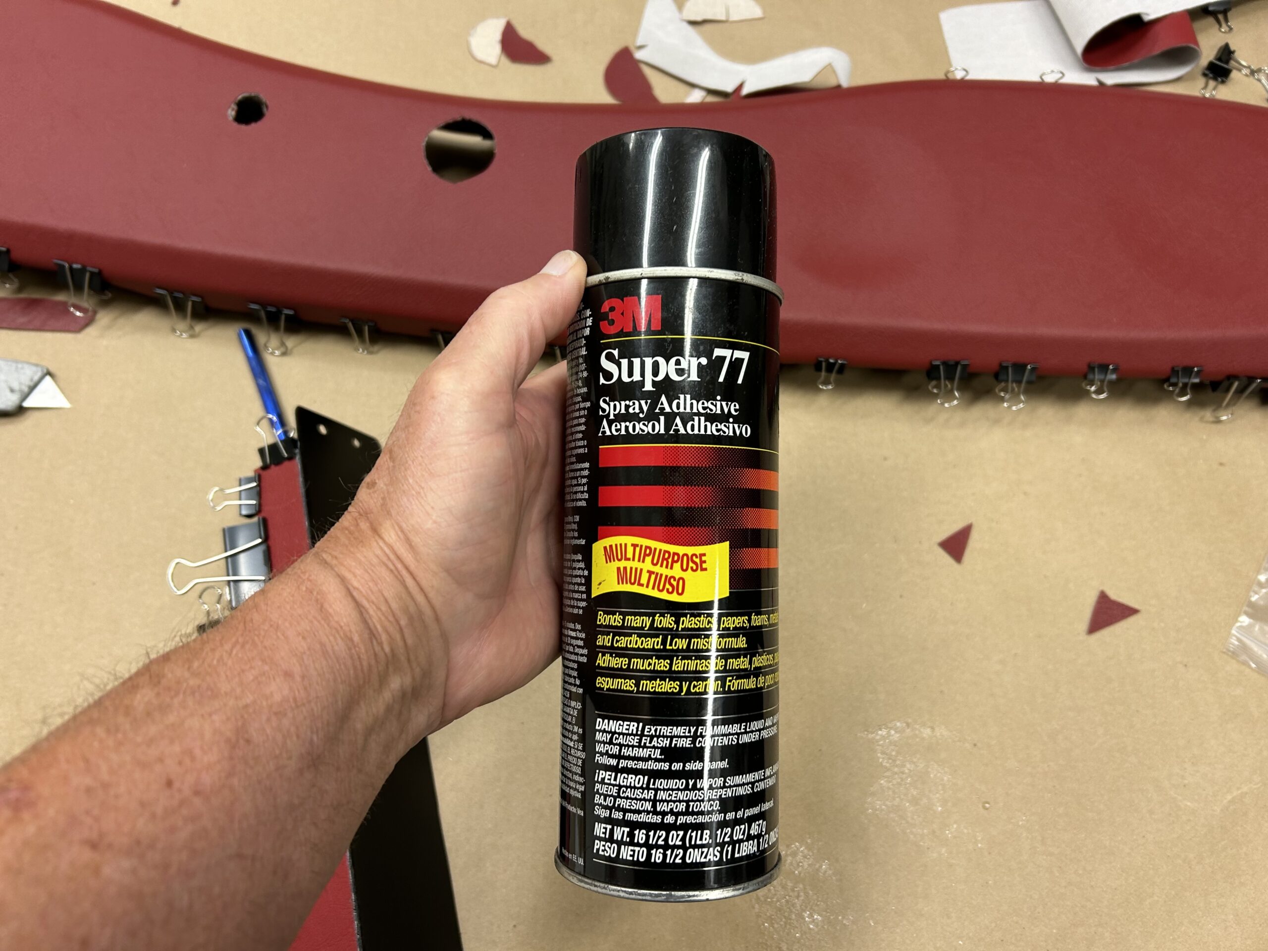
We fit the rear courtesy lights to each of the rear boot trim panels. We purchased the panels from Bugeyeguys.com. They required considerable trimming to fit them to the car, but once achieved we were able to mount the lights and complete the necessary wiring. The panels will eventually be covered in a red vinyl that matches the other interior panels.

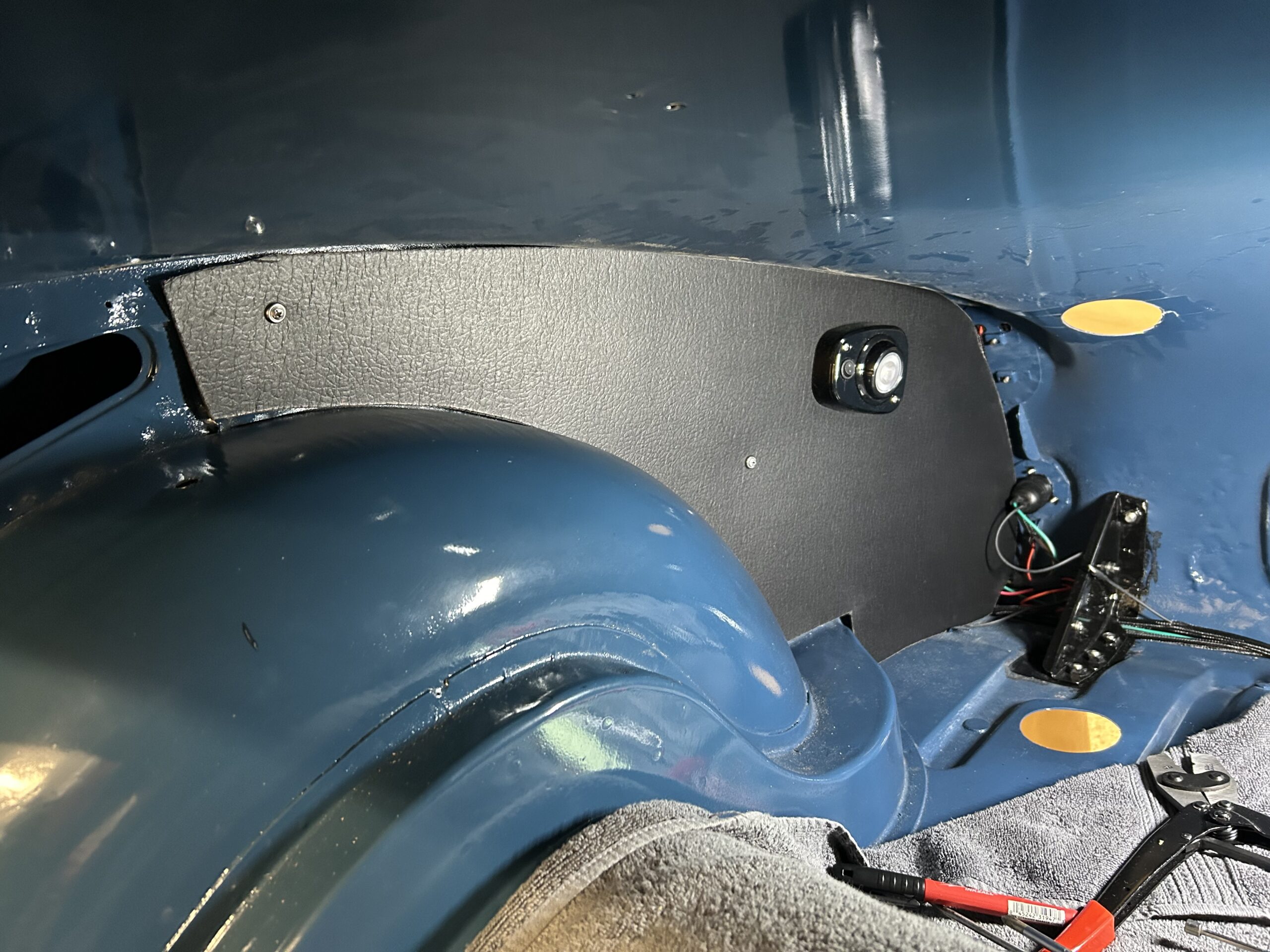
Rear Trim Panels and Courtesy Lights

In the rear we resorted to using rubber covered bullet connectors for a number of fittings. This was done because it is hard to reach into the back of the car and if it became necessary to separate wires for one reason or another it is easier to accomplish with the bullet connectors as opposed to the Deutsch connectors. Since weather isn’t an issue in the boot we should not experience any problems with the bullet connectors.

Once we established our wire lengths and connections we pulled the harness out of the car to send off to have them braided in black with the signature baby-blue tracer used in the Sprite. Originally, all of the wires to the rear of the car were bundled in one braided wire package and routed to the rear under the door sill and rear trim panels. Because we added wires to the mix we decided to bundle the wires into two four-wire groups to run in parallel under the panels. Hopefully this will cause the trim panels to protrude less and yield a nicer finished product.

Bugeye Restoration Video Episode Seventy-one shows the creation and installation of the electrical wiring in the rear of the car for the exterior lights, interior courtesy lights, the fuel pumps, and the fuel sender for the fuel gauge. Fitting of the rear trim panels is also shown.

https://vimeo.com/978445012/5aa017a2ba?share=copy

The following content is found in this video:

0:00 – Wiring for tail lights and flashers

1:24 – Spire nuts for side lights/flashers

1:40 – Wiring the side light/flasher fixtures

2:40 – Chrome trim rings and red beehive glass

3:25 – All rear lights mounted

3:36 – Internal rear lights wiring

4:17 – License plate wiring

5:39 – Dash “F” connector wiring to the rear of the car

6:15 – Bullet connectors for lights wiring

7:54 – Rear courtesy lights and trim panels

12:15 – Fuel pump wiring

14:43 – Facet fuel pump fuel filter

15:00 – Fuel level sender

15:42 – Floor rubber grommet for fuel sender wire

16:00 – Removing wiring to have Rhode Island Wiring braid the harness

16:28 – Taping the wires


Bugeye Seats

The MKI “Bugeye” Sprite seats were not particularly comfortable or supportive. This image shows the MKI seat design:

MKI Sprite seats

The previous owner was apparently aware of this shortcoming because the seats in the Bugeye are from a MK2 Sprite. These look very similar to a MKI Big Healey, but are not quite the same. Note the horizontal seam in the seat back – it distinguishes the Sprite seat from its big brother..

MK2 Sprite seat upholstery

We are going to have Geoff Chrysler, owner of Rightway Heritage Trimming, https://www.rightwayheritagetrim.com provide the seat upholstery. Unfortunately, new foam cushions for the MK2 seats are not available and Geoff is not pleased with the premade seat covers available from the usual vendors, so he will make and install the new covers himself. We will be going with red and red piping. We will send the foams we have along with the vinyl covers to Geoff so that he can use them as patterns. Bugeye Restoration Video Episode Sixty-one shows the deconstruction of the lower and upper seat cushions in preparation for sending to Geoff.

https://vimeo.com/955906748/05d8772bd1?share=copy

Our next step was to prepare the seat pans, the seat bases and the upper seat backs for shipping. Unfortunately, we discovered that the seat pans were not usable without some major rust repairs. Bugeye Restoration Video Episode Seventy shows the seat components and their condition.

https://vimeo.com/972539064/c702e9e1bc?share=copy

We discovered that Kilmartins http://www.kas-kilmartin.com.au  in Australia fabricates the correct seat pan so we ordered a pair and had them sent directly to Geoff. One of the seat backs had a pivot hole that was out of round so my friend Randy kindly brazed a washer on the inside of the seat to provide a nice new fit.

Seat Pivot repair 1

The seat bases were in good shape but the slider tracks were not. We drilled out the rivets that fasten the slider tracks to the base and removed them. We have purchased some used tracks that we will secure when the seat assemblies come back from Geoff’s shop.

Seat Base

Several of the pivot bolts had stripped threads. We located some new weld studs that seem identical to the originals and Randy welded them in place for us.

Seat Pivot Studs

We media blasted the seat backs after repairs, treated them with a rust preventative and painted them with two coats of POR 15. Now they are nice and shiny and ready to go to Geoff.

Painted seat backs

Dashboard Upholstery and Assembly

We were eager to see what the red interior upholstery was going to look like with the Cotswold Blue paint. The interior upholstered panels from Bugeyeguys arrived and so we set the panels in place to have a look. We are biased, of course, but we are more than pleased. We think we hit upon a beautiful color combination. The photo appears to brighter than the red actually is. The dash vinyl matches the interior panels and is a truer color depiction.

Interior panels

Next, it was time to wrap the dash in the matching red vinyl. We need to install the assembled dash in the car so that we can complete our wiring harness to the rear of the car. So after glueing the vinyl to the dash with 3M 77 adhesive we also installed all of the gauges and most of the switches.

3M Super 77 Adhesive

We held off on those items that extend through the firewall such as the water temperature and oil pressure gauge, the heater switch, as well as the choke, and starter switches/cables. In addition we covered the face of the hidden switch panel under the dash and installed its components.

Finally we made all of our electrical connections and temporarily installed the dash in the car. The entire process is shown in the Bugeye Restoration Episode Sixty-nine Video

https://vimeo.com/960749153/8aa0edf407?share=copy

The following steps are addressed in the video:

0:00 – Interior panels arrive

0:13 – Cockpit aluminum trim

1:11 – Dash vinyl applied

2:48 – Hidden switch panel

4:12 – Cutting holes in the covered dash

4:30 – Upholstery clips

5:00 -Grab handle and RH ground bus bar

5:30 – Washer pump install

6:18 – Ignition switch

8:18 – “D” and “F” connector harnesses installed

9:20 – Turn indicator warning lamp

9:30 – Fuel gauge

10:00 – Turn indicator switch

10:20 – Turn indicator warning lamp

11:00 – Fuel gauge

11:19 – Wiper switch

11:37 – Speedometer, tachometer, panel light switch and wiper rheostat knob

11:50 – Panel light switch

12:12 – Power inverter cube

12:18 – Dash wiring complete

13:44 – Disconnect instructions for dash removal from the car

14:55 – Completed dash

15:27 – Hidden switch panel

15:47 – Dash temporarily installed

And now on to the rear electrical connections and the wiring harness completion.


Front Shocks and Rear Bumpers

We know, this is an odd combination of things. The installation of the shocks was driven by a need to get something substantial mounted on the car. Silly, but gratifying.

Front LH Shock Installed

The rear bumpers, on the other hand, were installed for a very practical reason:  because we wanted something to hold onto at the rear of the car to move it around the garage on its dolly. Pushing the car by placing one’s hands on the boot area just didn’t seem like a good idea with fresh paint.

Bugeye Restoration Video Episode Sixty-eight shows the installation of the front shocks and the rear bumpers:

https://vimeo.com/960378353/c6dafdba0f?share=copy

0:00 – Front shock absorbers installation

1:06 – Rear bumper installation

Home From Paint

On June 3, 2024 most of the Bugeye came home from the paint shop. The doors, bonnet and few odds and ends remain to be painted, but it was nice to get the chassis home to begin the reassembly process. Most of the parts clean-up and painting have already been completed, so for the most part our next steps will be about getting everything back on the car.

This is an image of Gabor Fodor who painted the Bugeye. Obviously, pleased with his work.

A pleased Painter, Gabor Fodor

A Healey friend, Gary Cox, helped me get the car to the paint shop and he also helped us get the Bugeye home. Thank you Gary! Could not have done it without you, your truck and your trailer.

Bugeye Restoration Video Episode Sixty-seven shows the home delivery and the installation of the number identification plates on the car:

https://vimeo.com/960346111/7bf3cbd398?share=copy


Fire in the Hole

We had planned to run the engine on the starting stand with the gearbox fitted, but thought better of it. First, it would mean that we would have to figure out a way to keep the driveshaft fork in the nose of the gearbox so we would not leak oil out the end. However, more importantly, we wanted to inspect the clutch and the ring gear. So we modified the starting stand to include a mount for the engine rear backplate. 

We then hooked up the choke cable to the carb and we installed a lawn mower throttle cable and slide controller on the control panel and also hooked it up to the carb. These are shown in the video with the link below.

Water was then added to the radiator, Valvoline Racing Oil 20W-50 was added to the engine and some automatic transmission fluid was added to the HIF-44 damper. We then disconnected the coil and spun the engine with the starter until we had oil pressure. After checking ignition timing one more time, and testing for spark at the plugs. It was time to fire it up. It ran pretty well but seemed a bit rich at idle.

After a pause to work on other projects and to wait for parts, we came back to the engine to try to improve the engine’s tuning and to check on the clutch and ring gear.

The clutch had worked just fine but we decided to go ahead and replace the disc and pressure plate since the engine was out of the car. While we were at it, we also made plans to take the flywheel to a machine shop and have the face resurfaced and have the flywheel and clutch pressure plate, or cover, dynamically balanced. That is when things got interesting!

We took the flywheel to Southwest Hydraulics in Venice, Fl for resurfacing, but we got a call from them indicating that the flywheel was “coming apart.” As it turned out the flywheel had been lightened a bt too much and there was very little material between the flywheel lip and the ring gear. See below.

Flywheel delamination

This is going into the trash!

Since they no longer make steel flywheels for the 1275 (aluminum lightened flywheels are available) we searched eBay and located one. It had not been lightened at all which we preferred, but it was not without its problems. One of the clutch cover bolts had been broken off in the flywheel. Fortunately, our friend Randy Forbes came to our aid. Using his milling machine, he first flattened the top of the bolt shaft and then with his drill press using a LH drill bit he was able to remove the broken bolt with no adverse effect. Thank you Randy!

We then took the flywheel back to Southwest Hydraulics for the resurfacing and we also had them replace the ring gear with a new one sourced from A.H. Spares

Flywheel resurfaced

Then it was off to “VAMI” – Venice Auto Marine machine shop where we had the flywheel balanced. Unfortunately, we could not balance the clutch pressure plate with the flywheel because the center hole in the pressure plate was too small to fit on their machine. This should not be a problem as the pressure plate comes balanced by Borg and Beck. The new disc was sourced from Rivergate.

We then reinstalled the flywheel, clutch disc and clutch pressure plate. The flywheel bolts were new and torqued to 4o ft. lbs. A locking tab washer was installed and all the tangs were bent over. The clutch bolts were torqued to 19 ft. lbs.

In the meantime, we replaced the metering needle that came with the carb with a “BDL” needle to get some additional fuel at start up without having to rely so much on the choke. Randy Forbes again came to our aid with the installation of our oxygen sensor.

Oxygen Sensor Bung Installed

Randy doing his thing!

He installed a bung into our new exhaust pipe for the  oxygen sensor so that we could use our newly purchased Innovate Motorsports AFR gauge. This is very helpful in adjusting the fuel mixture at the carb.

Innovate Motorsports AFR Gauge

Before starting the engine a second time we also decided to replace the original-type Lucas starter with the gear reduction starter we had. 

We then started the engine a second time and we were pleased with the changes that had been made. The engine seems to be running well with a static advance of 12 degrees and a full advance of 31 degrees at 3,800 rpm. All of our changes and the first and second running of the engine are included in the Bugeye Restoration Video Episode Sixty. 

https://vimeo.com/953122217/a96f4deab1?share=copy

Episode Sixty includes the following content:

0:35 – Gearbox removal

2:30 – Throttle control

3:35 – Choke cable

4:40 – Engine fluids

6:35 – Priming the oil pump

7:35 – Checking for oil pressure

8:10 – Ignition timing

8:32 – TDC Compression stroke

9:00 – Checking for spark

10:35 – Engine starts!

11:30 – Ignition timing again

12:20 – Marking the distributor setting

12:30 – Gear reduction starter reinstalled

13:10 – Innovate Motorsports AFR gauge

14:08 – Engine running again

14:45 – Engine storage until it goes in the car

The exhaust was then removed along with the intake manifold, the HIF carb, and the exhaust header. This was done because we are sending the exhaust header to Jet-Hot for a ceramic coating. We have now covered the engine and pushed her to the side. The good news which is really too good to believe, and surely will not last, is that we have no oil leaks!

Wow, we started this engine work back in September of 2023. Considerable time has passed but we were continually diverted to work on other parts of the restoration. Other than coating the exhaust header we believe the engine is now complete. Hopefully, by Christmas she will be reunited with the car and it will be as easy as installing the engine and gearbox and taking the car for an initial run!


Custom Master Cylinder, Pedal Box and Hydraulics

Master Cylinders/Pedal Box

We had been using the original tandem master cylinder originally designed for the bugeye; however, it was a master cylinder sourced from Gerard Chateauvieux of Gerard’s Garage that was modified to incorporate 3/4″ bore pistons for the brakes and the clutch.

Twin Chamber 3/4″ Master Cylinder

Sebring Sprites used a custom pedal box with two offset Girling master cylinders with their own fluid reservoirs. We purchased a replica of the Sebring Pedal Box from Brookfab in the U.K. https://brookfab.co.uk/

We were quite pleased with the Brookfab assembly including the master cylinders, push rods and springs – very professional job.

Brookfab Pedal Box with Girling Master Cylinders

Brookfab Pedal Box

Brake Pipes and Hoses

All new cunifer copper alloy brake pipes with stainless fittings were formed and installed on the car for the 2024 restoration. In addition, Goodridge Stainless Braided (black) were also installed on the car. Both can be seen in the image below:

Cunifer Brake Pipes and New Fittings

Cunifer Brake Pipes and Goodridge Hoses

Brake Fluid

We have decided that because all of the brake system and clutch system are totally new we will use Dot 5 silicone brake fluid in the Bugeye.

Front Disc Brake Conversion

We bought the Bugeye in 1998 and shortly thereafter the car was taken to Grand Touring Classics, Inc in Stanarsville, VA for a safety inspection and a conversion to front disc brakes. Garland Gentry and his assistant took care of collecting the needed parts from a post 1964 Midget and installing them on the car. After some period of time we changed out the 7/8″ master cylinder for a 3/4″ which worked much better.

Of course, it is not as simple as just switching out the brakes. it is also necessary to install new stub axles and king pins, dust tubes and springs, hubs, back plates, calipers, hose brackets, rotors, pads with pad retaining plates with clips, new hoses with banjo bolts and copper washers. For the complete restoration of the car in 2024 all of the front brake components were updated and/or replaced. Parts were sourced from A.H. Spares and Moss Motors.

The front brakes, steering and suspension are integrated in assembly. Details of all of these  mechanicals are detailed in other posts regarding these subjects. The build up of the front hub assemblies and brakes ,may be found in this post: https://valvechatter.com/?p=13792   A video showing the assembly is included in the post.

Rear Drum Brake Upgrade

A common upgrade to the braking system for Bugeyes is the replacement of the rear  drum brakes which use a single action 7/8″ rear cylinder with later MG Midget rear brakes using a larger 3/4″ dual action rear cylinder. We were able to acquire the later backing plates, wheel cylinders, and brake shoes with springs, and handbrake levers from Gerard Chateauvieux of Gerard’s Garage. He indicated that the donor car was in the 1968-72 time frame.

Rear Brake Components

LH Rear Brake Assembly with Shoes and Cylinder

LH Rear brake assembly

The conversion also required using new crossbars or rods for the handbrake system as the original Bugeye crossbars are not shaped properly for the later brakes. These were purchased from Mini-Mania.

Adjustable Handbrake Crossbars

We did have problems with the drums rubbing against the backplates and had to grind away some material from the hub edge to avoid the conflict. 

More information about the build-up of the rear brake conversion including an assembly video that details the problems we encountered may be found in two other posts: “Rear Drum Brake Upgrade”  https://valvechatter.com/?p=13399 and “Bugeye Rear Axle Assembly” https://valvechatter.com/?p=13569 in the restoration series. These posts and their included videos show the mounting of the rear hubs and brake assemblies to the rear axle.

Redundant Electric Fuel Pumps

The Bugeye began life with a 948 cc four cylinder motor that had a mechanical fuel pump mounted to the engine block. We converted to an electronic SU negative ground 12 volt fuel pump years ago and it was mounted in the engine bay. Then we mounted the pump in the rear of the car as outlined in an earlier post: https://valvechatter.com/?p=13599

SU electronic fuel pump negative earth

The SU pump was sourced from AH Spares in the UK. After acquiring the Michigan body shell we decided to modify the fuel delivery system yet again to incorporate a redundant electronic pump to have a ready back up in the case of a pump failure. The back up pump was sourced from Pegasus Racing and it is a Facet Cylindrical pump rated at 2.75-4 psi.

Facet Cylindrical 2.75-4 PSI Negative earth electronic fuel pump

The two pumps are installed in series and will be wired with a toggle switch permitting the selection of either pump or no pump at all – an effective theft deterrent. Nut serts (1/4″-20) were installed in the rear bulkhead to serve as mounting points for the rubber isolators, also purchased from Pegasus, that fit between the bulkhead and the pumps. 

A new stainless steel pre-bent fuel pipe was purchased from Summit Racing, modified to accommodate the new pump setup and installed in the car.