Steering/Trafficator

Steering

I made no modifications to the original steering system consisting of the steering box, steering idler, and steering arms. However, both the steering box and idler were completely rebuilt.

Steering Wheel

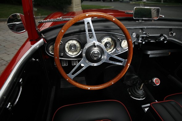
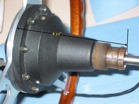
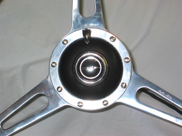
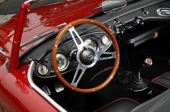
I did replace the original steering wheel with a Moto-Lita Mahogany Wood Wheel. This also requires adding a new hub.

Moto Lita Wheel

Moto Lita Wheel

Moto-Lita Hub

Moto-Lita Hub

Control Head/Trafficator

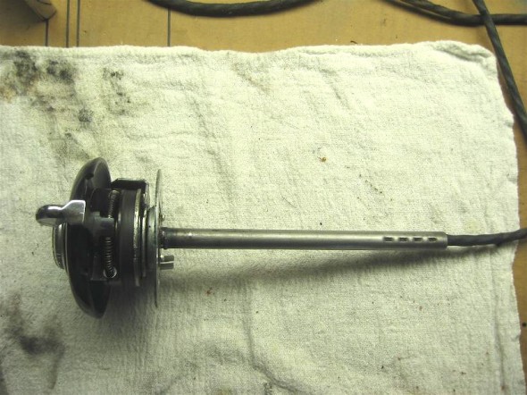
The control head or trafficator, as it is more often called, often needs a rebuild on our forty plus year old cars. The control head has the turn indicators with a self-canceling feature, and the horn button with wiring. I rebuilt my control head myself and benefitted from some of the images that Tracy Drummond had assembled. To try to help others I put together the following article:

Control Head (Trafficator) Rebuild for an Adjustable Wheel

July, 2005 – Revised October 2, 2005

Well, I have been putting off the task of rebuilding the control head to prepare it for installation in my Moto-Lita wood rim steering wheel. I rebuilt the original control head when I was in college and I don’t recall it being a fun task. Although, back then I did so without any instruction. Today I have the benefit of helpful tips from Norman Nock, Michael Salter, Steve Byers, John Trifari and Tracy Drummond and others. The notes below and some of the images are “borrowed” from their work. Tracy’s photos were particularly helpful.

If your control head or trafficator is fine, but you want to install a restored or new steering wheel, Roger Moment has provided some useful tips for partially disassembling the trafficator to permit switching out the wheel without pulling the wiring. His guidance is provided at the end of this article.

For starters I now know that the way to begin is not to pry up the bent tabs at the back of the unit! Instead, the process is much simpler but less obvious. Turns out the whole job was not as bad as I had remembered.

In my case I needed to completely rebuild my control head because the signal lever was broken and because I needed to install new wiring. I also wanted to improve the finish of the Bakelite head which had turned a bit brown with age. If one only needed to replace the wiring the suggestions from Michael Salter proved to be very helpful. That was my first step.

Read through these instructions completely before starting the disassembly!! If you don’t want to try this then I understand that Vic Wright ([email protected]) does a great job of rebuilding used units!

On the steering wheel, you will see three set screws on the steering wheel hub, forward of the spokes. Loosen (probably remove, to avoid losing them) the screws. The four wires that go to the control head need to be disconnected from the harness at the front of the car not far from where they exit the long stator tube at the steering box. The job is made easier if one simply cuts the bullet connectors off the wiring and then solders a wire or ties fishing line to the wire. Having the line attached to the wiring will make inserting the new wiring much easier than it would otherwise be. The line should just rest in the steering column until the replacement is ready to install. The control head with a short stator tube and the wiring can then be removed from the steering column by pulling straight out (not twisting). Neil Trelenberg suggests drawing a line on the stator (short and long) tube with a felt marker as a guide for realigning later.

Now to the disassembly of the control head unit:

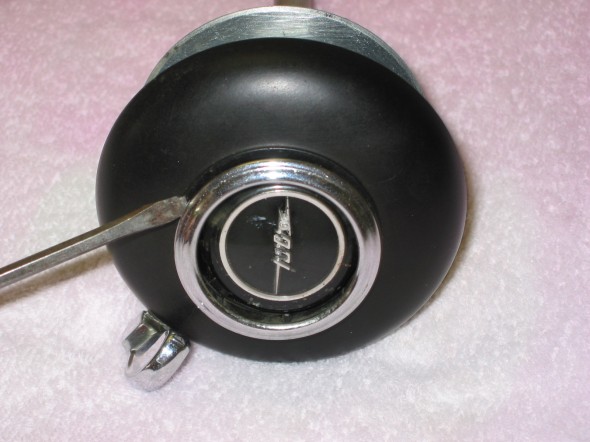
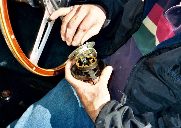
First, carefully pry the horn button trim ring away from the bakelite head being careful not to scratch it.

Trafficator Rebuild Image 1

Trafficator Rebuild Image 1

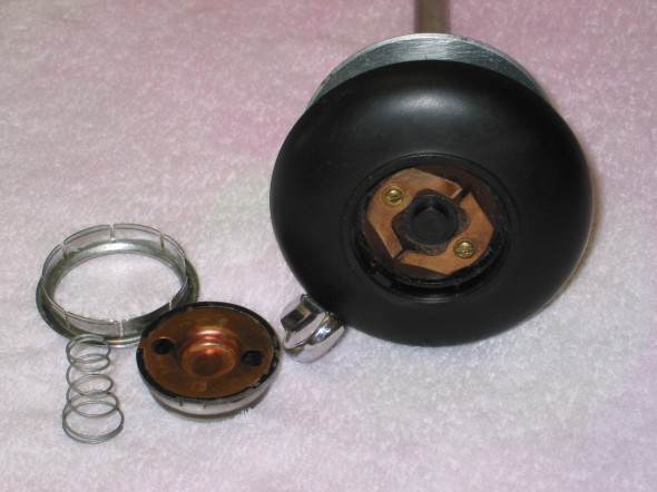
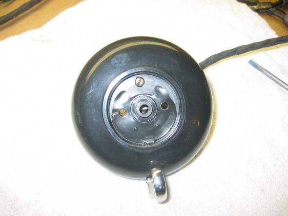
Once the horn button is loosened, the horn spring will be revealed. Its small diameter end faces to the bakelite head. The laminated blades of the horn switch secured by two brass screws also become evident.

Trafficator Rebuild Image 2

Trafficator Rebuild Image 2

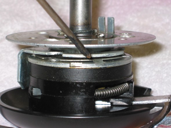
Examine the entire assembly. On the back of the unit, viewed from the side, a small tab bent down into a slot can be observed.

Trafficator Rebuild Image 3

Trafficator Rebuild Image 3

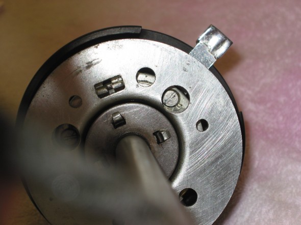
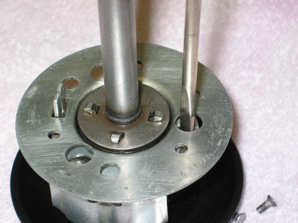
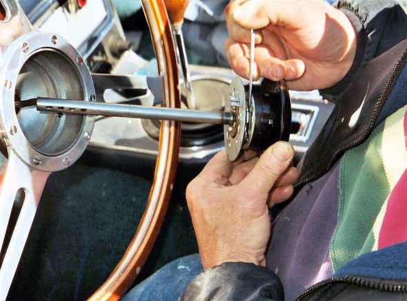
The tab can be pushed up so that it slides on the flat plate and the unit can be rotated slowly. Doing so provides access through 3 holes in the base mount plate to 3 slotted screws.

Trafficator Rebuild Image 4

Trafficator Rebuild Image 4

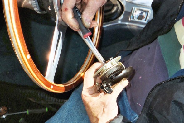
Before removing the three screws, make a note or reference mark of how the two halves of the unit secured by the three screws goes together. Then remove the screws. The correct orientation of the turn signal lever is straight up, but if the two halves are oriented incorrectly, the turn signal lever will be either pointed down, or off to the side.

Trafficator Rebuild Image 5

Trafficator Rebuild Image 5

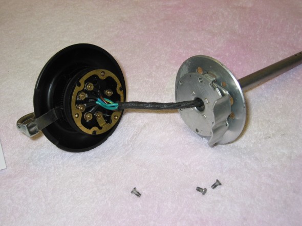
The stator tube, base plate, locating plate, the base mount plate and assorted washers and spring can then be separated from the bakelite mounting plate and head. This assembled unit does not need to be disassembled. It can be pulled off the wires and set aside for assembly later.

Trafficator Rebuild Image 6

Trafficator Rebuild Image 6

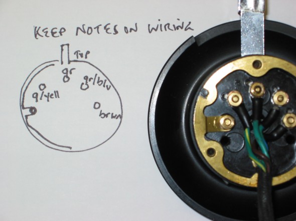
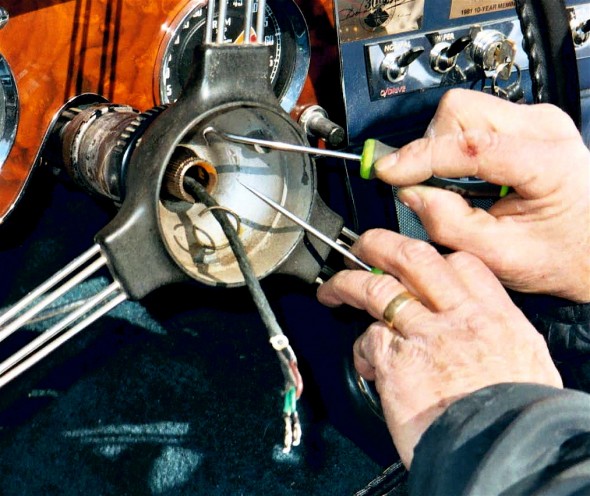
Examine the back of the mounting plate. There are six nuts visible. Three are for the turn signal switch, two are for the horn (one goes through the brass gound ring) and the one without an attached wire is to hold the head and the mounting plate together (It is barely visible in the photo under the wiring sheath). Make a drawing to illustrate the color code and where each of the wires should reconnect to its proper fitting.

Trafficator Rebuild Image 7

Trafficator Rebuild Image 7

If your plan is to install a new wiring harness only and you do not wish to disassemble the control head to access the turn signal switch it is IMPORTANT to install the new wires onto the screws one wire at a time.

A. The screw on the right in the photo is accessed under the horn button. Hold it with a screw driver and loosen the nut holding the wire, remove the nut, change the wire, refit and tighten the nut.

B. The nut second from the right is held in place by a hex head screw recessed in the bakelite mounting plate. The turn signal lever must be moved so that it is aligned behind the screw/nut. It will hold the screw in place permitting removal of the nut and old wire, change the wire and refit and tighten the nut. Do not let the turn signal lever slip while doing this procedure or you will likely be disassembling the complete unit!

C. Reposition the turn signal lever to the center position and repeat B. above for the screw/nut located third from the right.

D. Move the turn signal lever behind the screw/nut located fourth from the right and repeat B. above.

If all you are doing is replacing the wiring you are finished. Leave the screw/nut to the far left, through the horn ground ring, alone.

Feed the wire through the base plate and the stator tube. Reinstall the three base plate screws with the trigger opposite the turn signal lever. I found it easiest to install the screws with the unit on its side. Don’t forget to then reposition the thin plate with the locating tab to the slot and push it down. Reinstall the horn button, spring and chrome trim ring. Note that the button and ring have a locating notch that matches up with the bakelite head.

I recommend cutting the bullet connectors off the wires, solder the wire or tie the fishing line left in the steering column, to the new wires and slowly pull the new wiring harness through the stator tube and out the end of the steering box. The fit of the harness in the tube is tight so it might be best to tape the wire ends together as they are pulled through. The short stator tube fits down and into the longer stator tube in the column. The tubes go together in only one orientation, directed by the dimples found on the side of the short tube.

If you are installing the control head into a non-stock wooden steering wheel you may need to install a shim (I used the plastic top of a yogurt container) inside the hub between the hub and the control head to move the control head toward the driver slightly so that the turn signal lever does not contact the wheel ring. Then reinstall the three set screws to tighten the control head to the wheel hub.

Cleaning or repairing the turn signal mechanism. 

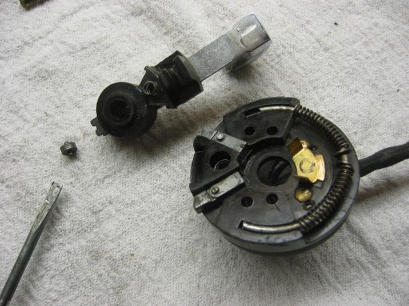
Remove the two screws holding the laminated blades of the horn switch under the horn button. The horn switch will lift out. The third screw can then be removed and the bakelite head can then be separated from the mounting plate.

Trafficator Rebuild Image 8

Trafficator Rebuild Image 8

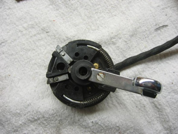
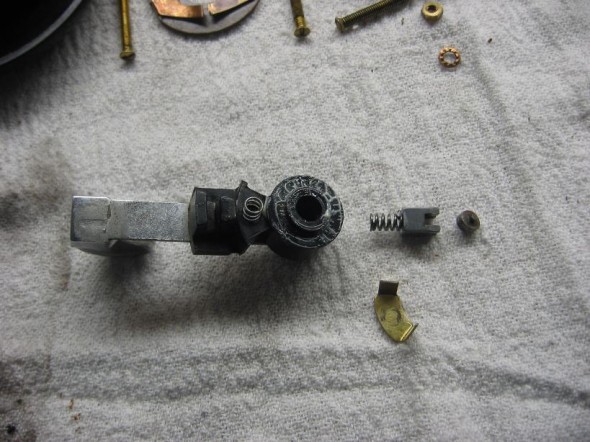
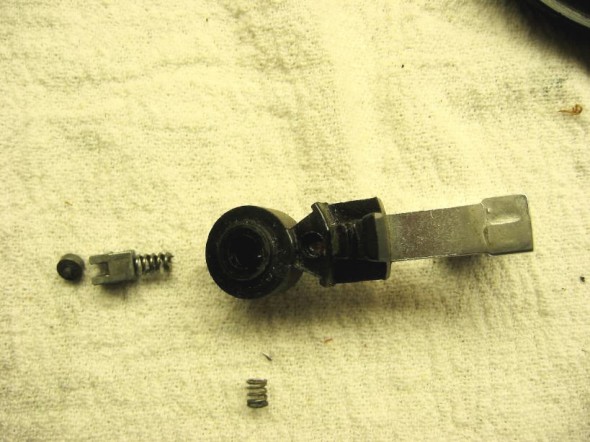
The turn signal lever is attached with one screw to the back of the bakelite mounting plate. Underneath it is a curved wire with a spring on each side of the lever.

Trafficator Rebuild Image 9

Trafficator Rebuild Image 9

Trafficator Rebuild Image 10

Trafficator Rebuild Image 10

There is another little spring and ball at the bottom of the turn signal lever.

Trafficator Rebuild Image 11

Trafficator Rebuild Image 11

If you carefully remove the single screw to separate the  lever from the assembly, the springs and small parts should stay in place. Note how they should be reassembled, then take apart, clean and lubricate with a little lithium grease.

Trafficator Rebuild Image 12

Trafficator Rebuild Image 12

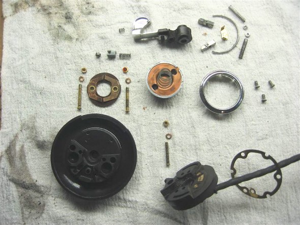
If you experience an explosion of parts, don’t be alarmed. It will all go back together! All components are identified in the photo below:

Trafficator Rebuild Image 13

Trafficator Rebuild Image 13

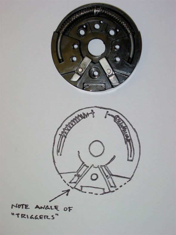
The proper positioning of the two hinges or “triggers” is important. They have angles on the end that fit opposite each other. They need to be placed as seen in the image and drawing for the canceling switch to work. Before reassembly of the complete unit, now is a good time to refinish the bakelite if it is needed.

Trafficator Rebuild Image 14

Trafficator Rebuild Image 14

Refinishing the Bakelite Head

I have lost the source of these instructions or I would give attribution, but clean the head well and wipe with a liquid cleaner like the type used before spray painting metal. Then apply black India ink. I used two coats letting the first coat dry for about an hour before applying the second. Then use black paste shoe polish rubbed in well. Polish. Reapply paste and polish again. Finally, apply a coat of carnuba wax for protection and final shine. Be very careful to not drop the bakelite head! I recommend doing all the polishing over a carpeted floor in case the head is dropped. This should result in a control head that looks brand new.

Trafficator Rebuild Image 15

Trafficator Rebuild Image 15


Assembly

Carefully place the head and the mounting plate together pushing the spring at the end of the turn signal lever into the mounting plate. Holding the two pieces together install and tighten the single screw and nut at the bottom of the unit. This screw/nut will securely hold the two pieces together while the horn switch screws and nuts are inserted and tightened.

Trafficator Rebuild Image 16

Trafficator Rebuild Image 16

I recommend, based on the comments of others and my own experience, cutting the bullet connectors off the wires, solder the wire or tie the fishing line left in the steering column, to the new wires and slowly pull the new wiring harness through the stator tube and out the end of the steering box. The fit of the harness in the tube is tight so it might be best to tape the wire ends together as they are pulled through.

Steve Byers took a slightly different approach that certainly makes taking the wiring through the stator tube easier. He commented, “although I have been able to pull the harness out of the column with the connectors installed, I have never been able to put it back in no matter how tightly I taped/wrapped the connectors together.  The last time I did this, I installed a new steering column harness as a part of a general re-wiring.  To make it easy on myself, I cut off all the bullets from the new harness (leaving about 3/4″ of the wire attached to each), fed the harness through, and then soldered the bullets back on with a piece of heat-shrink tubing over the splice.  The key is, I did not twist the wires together before soldering but soldered them together as they lay side by side.  That way, next time the harness needs removing it will be easy to remove the bullets without damaging the wire, and that can be done many times without damage to the wires.”

The short stator tube fits down and into the longer stator tube in the column. The tubes go together in only one orientation, directed by the dimples found on the side of the short tube.

If you are installing the control head into a non-stock wooden steering wheel (Moto Lita, Derrington) you may need to install a shim (I used the plastic top of a yogurt container) inside the hub between the hub and the control head to move the control head toward the driver slightly so that the turn signal lever does not contact the wheel ring. Then reinstall the three set screws to tighten the control head to the wheel hub. The job is complete! Now the control head (horn and turn signal control switch) will look and work as well as the rest of your car.

Roger Moment’s tips for installing a new steering wheel or repairing the trafficator without removing the wiring.

For those who are really bold and experienced Roger Moment has informed me that it is possible to complete a trafficator repair or replace a steering wheel without having to pull the wires up through the stator tube. I have no personal experience with this approach so I cannot comment on the degree of difficulty, but if Roger says it can be done, then it can! However, he emphasized that it should only be attempted by those who are totally familiar with the disassembly of these units.

The relevant steps are:

Unclip the end of the steering column harness so that there is about 8″ or more of slack.  This is accomplished by locating the clip that holds it to the cross brace in front of the radiator.

Back off the three retaining pointed screws in the steering wheel hub.

Pull out the head enough so that it can drop down across the front of the steering wheel.

Push up and rotate the retaining tab as seen in Image #3 and below in Image 17.

Trafficator Rebuild Image 17

Trafficator Rebuild Image 17

Remove the three screws securing the mounting to the backing plate.

Trafficator Rebuild Image 18

Trafficator Rebuild Image 18

Then separate the backing plate:

Trafficator Rebuild Image 19

Trafficator Rebuild Image 19

One can then remove the wires as described earlier in this article, using the technique with the lever to “back up” the contacts so that they don’t fall into the head.  It is very important to replace the nuts immediately after removing each wire!

Once the wiring has been removed from the switch assembly, if you are only going to repair it you can leave the wire loom in place in the short sliding part of the stator tube. However, if you are planning on removing the steering wheel to replace it, you must first draw the wires back through the short tube.   This is easily done by first folding only twoof the eyelets tightly back against the wires, leaving the other two extending straight. This creates a “package” that is compact enough to slide through the tube.  Next remove the circlip and pull the steering wheel off the shaft.

Trafficator Rebuild Image 20

Trafficator Rebuild Image 20

Roger indicates that this “in-car” method will also work on non-adjustable steering set-ups (on 100s and those few 6-cylinder cars that are equipped as such).  However, here the entire stator is drawn up after loosening the clamping nut. The steering box oil will drip out around the wires at the end during the time that the tube is partially withdrawn. As soon as the wires are freed, the tube can be re-inserted and the nut re-tightened.  You’ll only lose a bit of the oil and it still beats reinserting the entire tube.

Roger suggests that if you do draw out the tube, use a 3/8″ bolt with a good 1″ or so of smooth shank to re-insert into the nut and olive at the steering box to keep most of the oil from draining out.  This bolt is then removed when the tube and wires are put back through.

Happy Healeying and Cheers!

Lin Rose

1960 BT7

1959 Bugeye


July 7, 2005

Revised October 2, 2005

Click this link for a pdf of the trafficator rebuild: Trafficator Repairs Low Res


Assorted Interior Modifications

Original Interior

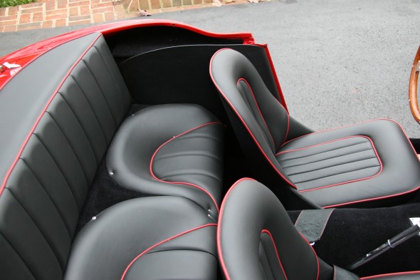
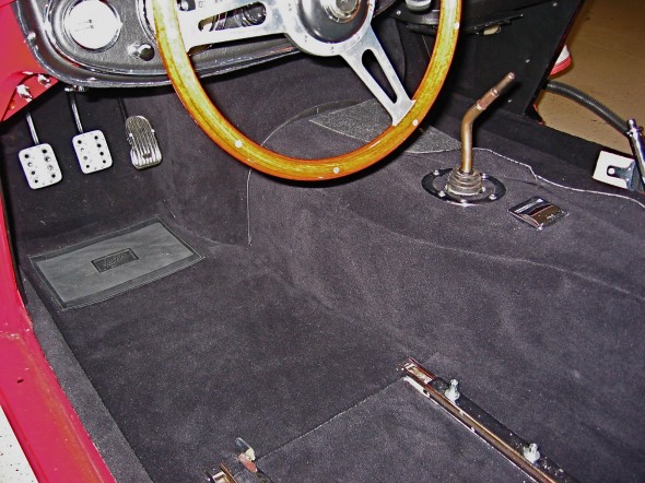
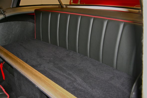
The original interior was medium red with black piping using leather and matching “leathercloth” vinyl. Carpet was also red and black armacord finished the boot interior. An adjustable plastic 16 1/2” steering wheel was standard.

Interior Modifications

Upholstery and Carpet

The interior finish materials were supplied by Heritage Trim. http://www.heritagetrim.com/. While somewhat expensive and not particularly fast on delivery, they provide a premium product with top grade materials. As the images show, I decided on black leather upholstery with red piping. Although I would have preferred a brighter red material for the piping, I was quite pleased with Heritage Trim.

Heritage also supplied the carpet, and while a material very close to the original is available, I decided to go with Wilton Wool which is a softer cut pile and to my view a more elegant look.

Heritage Interior

Heritage Interior

 Steering Wheel

The Steering Wheel was replaced with a Moto-Lita wheel made of mahogany wood. It is ordered with a complimentary hub so that the original control head (trafficator) and horn button may be used.

Moto Lita Wheel

Moto Lita Wheel

 Fiberglass Gearbox Cover

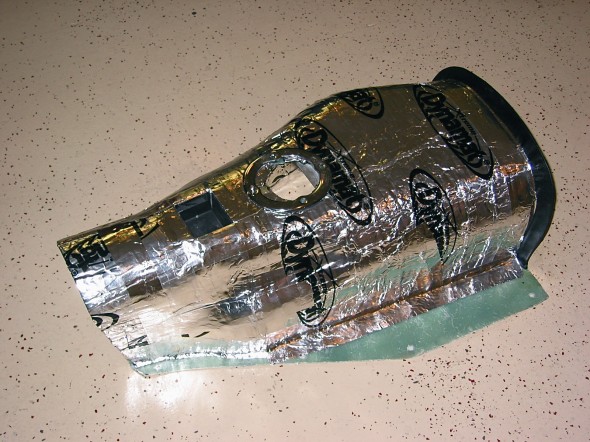
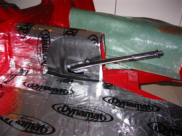
Using a Toyota five speed gearbox required relocating the hole for the shifter in the gearbox cover from the original side mount to a center location. A fiberglass cover is available from http://www.britishcarspecialists.com/. The fiberglass cover is lighter, cooler as it does not conduct the heat like the original metal cover, and was easy to modify. I covered the gearbox cover with Dynamat Extreme and an additional layer of aluminum duct insulation to keep things cool.

Fiberglass Gearbox Cover

Fiberglass Gearbox Cover

Interior Insulation

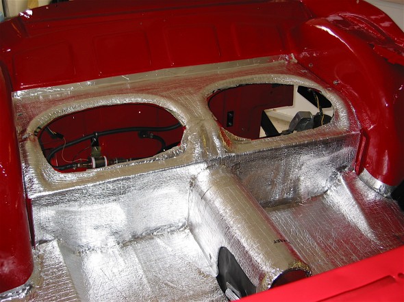
Anyone who has ever driven a stock Healey knows that the interior, particularly in the footwells, can get quite toasty but the combination of sealing firewall holes and installing modern insulation materials can virtually do away with the cockpit heat. I used Dynamat Extreme in the Bloody Beast and then installed a layer of aluminum backed foam duct insulation used in home HVAC systems on top of the Dynamat. All gaps between the pieces of insulation were covered with aluminum tape.

Dynamat Extreme

Dynamat Extreme

Interior Insulation

Aluminum Interior Insulation

Tilted Driver’s Seat

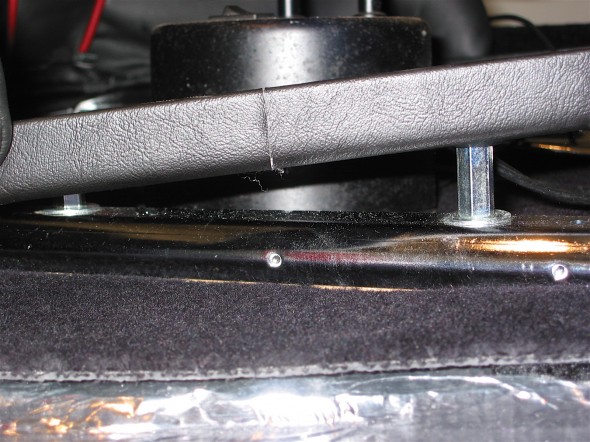
Big Healeys have reasonable legroom for those of us who are over six feet tall, but the designed seating arrangement places the driver very close to the steering wheel. One way to improve on the situation is to add spacers of varying lengths to the studs on the seat rails. The effect is to create a slight rearward tilt to the seat that then permits a little more arm extension for driving. I just picked up the extensions at the local hardware store.

Tilt Seat

Tilted Seat

Cup Holder

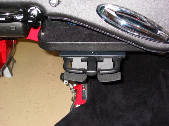
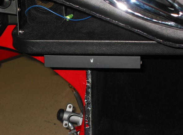
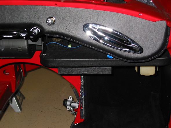
While I do not permit any beverages in the Bloody Beast other than water, the good ol’ American cup holder is a convenient accessory to the Healey interior. I borrowed the idea from Roger Conte – Ausmhly [email protected]. I used a Volkswagen Jetta cup holder #1J0 858 601D and mounted it under the parcel tray. Works like a charm and virtually hidden when not in use. This link will navigate you to the detail page on the cup holder: https://valvechatter.com/?p=3487

Cup Holder Empty

Cup Holder Empty

Alloy Pedal Covers

Just to dress up the pedals a bit and to provide an improved pedal surface, I installed alloy covers on the original pedals. My brake and clutch pedal covers were custom made and a gift from buddy Mick Nordquist, while the accelerator pedal came from Denis Welch Motorsport http://www.bighealey.co.uk/content/wider-accelerator-pedal.

Alloy Pedal Covers

Alloy Pedal Covers

Arm Rest/ Console

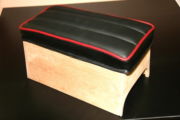
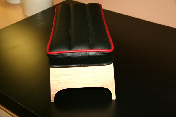
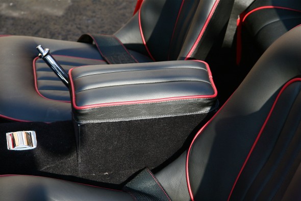
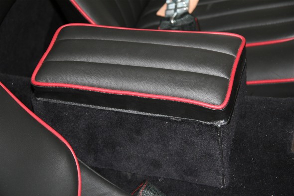
The padded arm rest provided as original equipment in the MK1 interior, while attractive in appearance, was pretty useless in that it was too low for one to actually rest an arm on the pad while driving. I decided to use the cushion as supplied by Heritage Trim to fabricate the top of a box or console to be installed on the gearbox/propshaft tunnel.

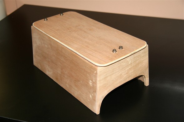
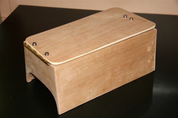
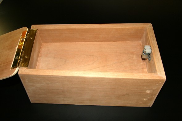
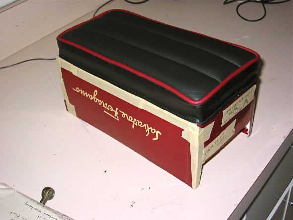
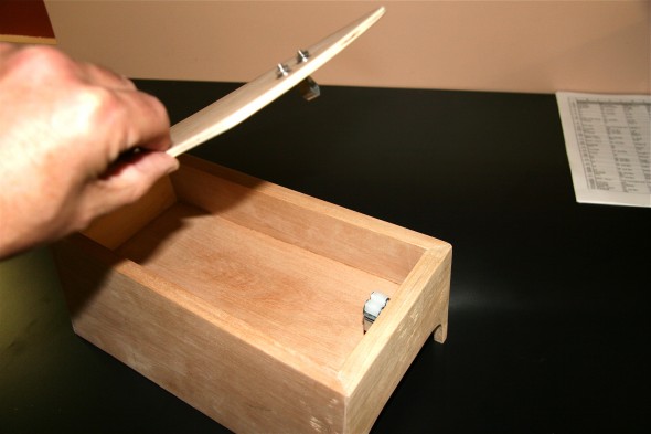
I began to form my idea for the console by fitting a cardboard shoebox to what I considered to be ideal dimensions, and then built a wooden box to provide some storage along with a fully functional arm rest. I encountered the need for lots of weird angles, but eventually got it all worked out and was very pleased with the outcome. After hinging the top, I covered the box in the wilton wool carpet and created something that appears original to the untrained eye. I could have permanently mounted the box to the tunnel but chose not to do so. This allows me to reposition the arm rest as desired.

Console Installed

Console Installed

Console Box

Console Box

Console Box

Console Box

Console Interior

Console Interior

Console Box

Console Box

Console Lid

Console Lid

Console Installed

Console Installed

Rear Luggage/Parcel Shelf

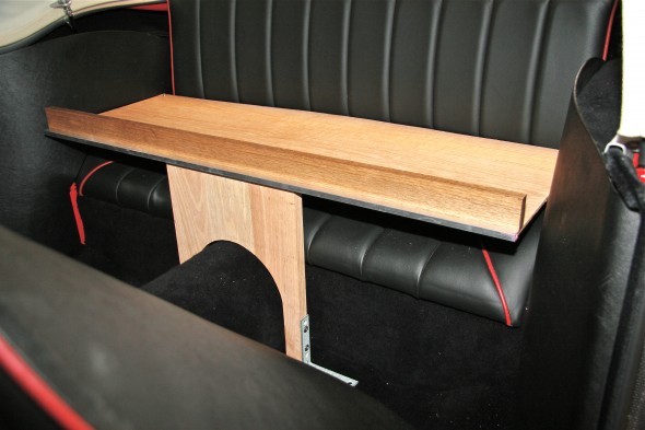
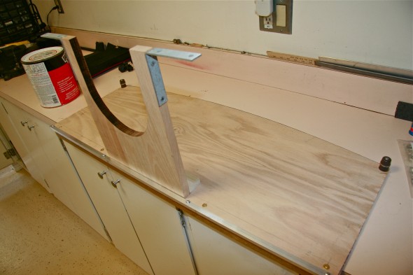
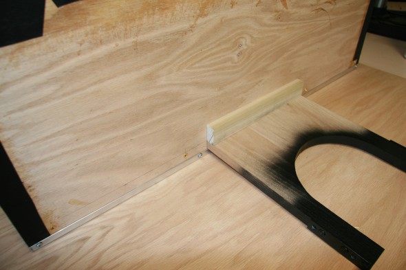
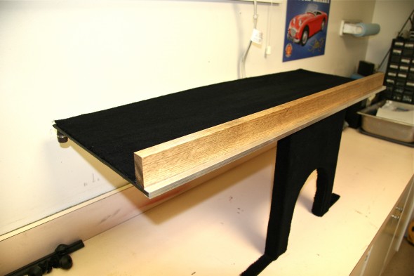
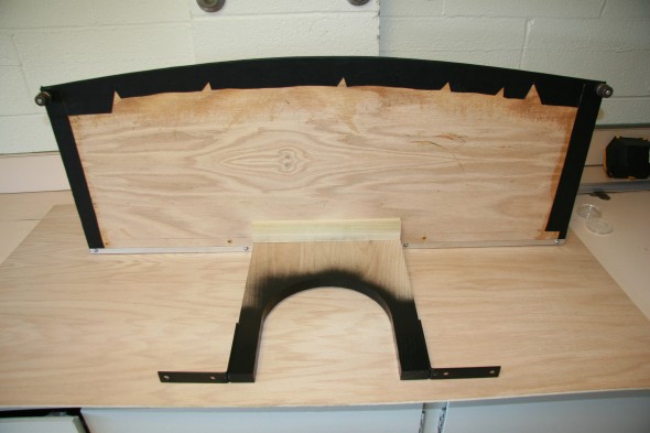
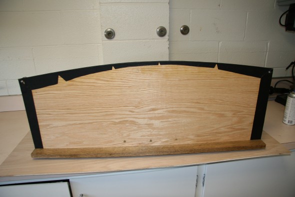
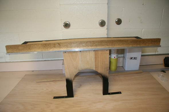
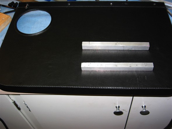
MKIII owners have a nice luggage shelf behind the front seats if they need more storage space, but MKI owners didn’t have that convenience. Inspired by my upcoming cross-country trip, I decided to bold my own. The shelf is completely removable, but alas, unlike the BJ8 owner, I cannot just fold my up and out of the way. In my case, I either travel with it, or without it. This is the link to assembly directions and more images: https://valvechatter.com/?p=3508

Luggage Shelf

Luggage Shelf

Luggage Shelf

Luggage Shelf

Luggage Shelf

Luggage Shelf

Luggage Shelf

Luggage Shelf

Luggage/Parcel Shelf Image 6

Luggage/Parcel Shelf Image 6

Spare Tire Cover

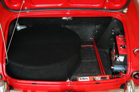
While not technically the “interior,” I wanted to dress up the boot for appearance purposes nut also to protect clothes or other objects place in the boot that would have been exposed to a spare tire. I had a local upholstery shop sew a cover for me. I then cut a slot in the rear for the hold-down strap and I was in business. It makes for a much cleaner look in the boot.

Spare Tire Cover

Spare Tire Cover

Rear Luggage/Parcel Shelf

Luggage/Parcel Shelf

This is a pdf file of the assembly plans for the luggage/parcel shelf, followed by several images of the assembly process:

BT7 Parcel Shelf


Luggage/Parcel Shelf Image 1

Luggage/Parcel Shelf Image 1

Luggage/Parcel Shelf Image 2

Luggage/Parcel Shelf Image 2

Luggage/Parcel Shelf Image 3

Luggage/Parcel Shelf Image 3

Luggage/Parcel Shelf Image 4

Luggage/Parcel Shelf Image 4


Luggage/Parcel Shelf Image 5

Luggage/Parcel Shelf Image 5


Luggage/Parcel Shelf Image 6

Luggage/Parcel Shelf Image 6


zz

Cup Holder

Cup Holder

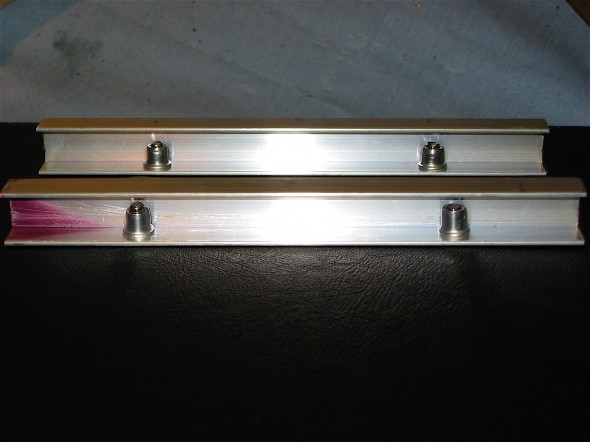
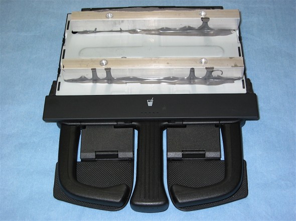
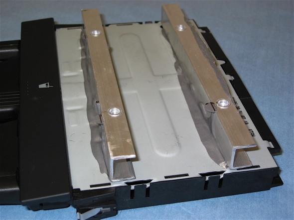
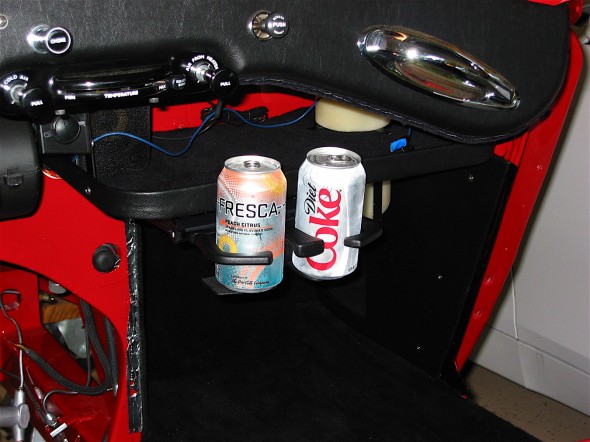
You just can’t drive a car in the States that doesn’t have a cup holder. Somehow it would be un-American! I borrowed the idea from Roger Conte who installed one in his BJ8. You can’t hide it quite as well in a BT7, but with a few mounting modifications I added the same VW Jetta cup holder in the Bloody Beast.

An article about the installation of the cup holder in both cars was included in the October 2009 issue of the Healey Marque. A pdf of that article may be found here:  Healey Marque Cup Holder Article Low Res
The following images may also provide some help to others who may be interested in doing the same:
Cup holder bracket Image 3

Cup holder bracket Image 1

Cup Holder Bracket Image 4

Cup Holder Bracket Image 2

JB Weld Aluminum Bracket Image 5

JB Weld Aluminum Bracket Image 3

JB Weld Aluminum Bracket Image 6

JB Weld Aluminum Bracket Image 4

Original Cup Holder Door Image 7

Original Cup Holder Door Image 5

Vinyl Covered Cup Holder Door Image 8

Vinyl Covered Cup Holder Door Image 6

Cup Holder Empty Image 7

Cup Holder Empty Image 7

Cup Holder in Action Image 8

Cup Holder in Action Image 8


zz

Armrest/Console

Creating a Functional Arm Rest  for a BT7

A number of people have asked about the arm rest installed in The Bloody Beast, so I decided to write up a little summary of the build process.

I began with the standard upholstered arm rest pad sourced from Heritage Upholstery and Trim. However, the pad as original, is virtually useless as one would never “rest” their elbow on a pad mounted as low as an inch or so above the gearbox cover. I also thought, “well, if I am going to raise the height of the arm rest pad, then why not build a little storage into the new design?”

I first prepared a mock-up using a cardboard shoe box and some masking tape. The pad is wider at the front then in the back so the appropriate alteration needed to be made to the measurements of the cardboard model.

Arm Rest Prototype

Arm Rest Prototype

My plan from the beginning was to cover the box with matching black carpet and hinge it at the rear of the pad. For me, 2 3/4” appeared to be the proper height of the box, with the cushion on top of the box. Each person fabricating a similar console might want to check the vertical measurement to arrive at a comfortable “at rest” position for them.

I don’t own any woodworking tools so I asked a carpenter friend to finish my box. We did a few trial and error fittings along the way. You really have to do this because the shape of the gearbox cover means that that the angled and curved cuts for the sides as well as the front and back are all different.  Would you expect anything else with a Healey?
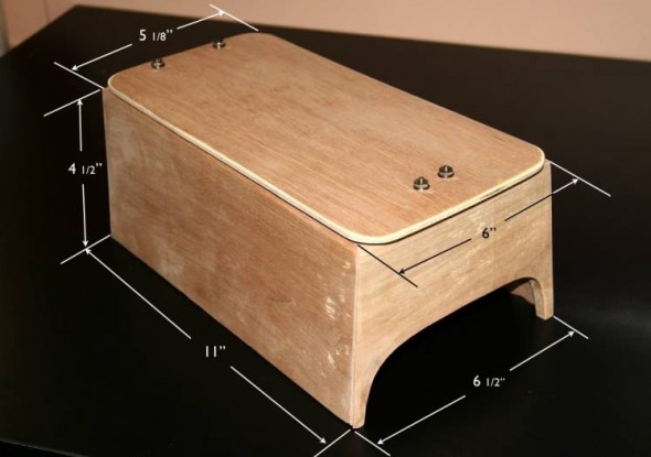
Arm Rest Dimensions

Arm Rest Dimensions

These are the dimensions of the box we ended up using. I made the box slightly shorter (3/8”)than the upholstered pad so that you would have a “lip” to grab hold of to lift the top away from the box. The box is glued together using Elmer’s Wood glue and it has held up just fine, although I am careful to not put too much weight (stress) on it as I enter and exit the car.

I used brass piano hinge for the rear of the box and a pressure clip cabinet catch for the front. I used the clip rather than a magnet to keep the top centered on the box.

Arm Rest Hinge

Arm Rest Hinge & Clasp

Arm Rest

Arm Rest

Arm Rest

Arm Rest

Arm Rest

Arm Rest

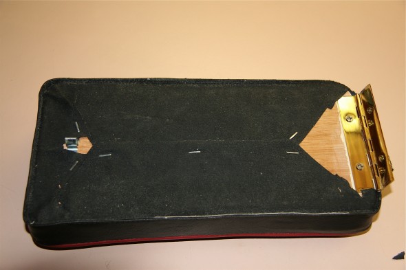
I cut an opening in the fabric on the bottom of the upholstered arm rest and slid the wood top of the box into the arm rest pad and stapled it in place.

 
Arm Rest Cover

Arm Rest Cover

Arm Rest

Arm Rest

Arm Rest

Arm Rest

I had ordered some extra black carpet from Heritage Upholstery and Trim and I used it to then cover the box. I used a little vinyl piping for the front edges where the carpet edges meet to give a finished appearance. Now I have something that looks almost as original, and it also is comfortably functional! The little box is great for gloves, tire pressure gauge, car registration and insurance cards and etc.

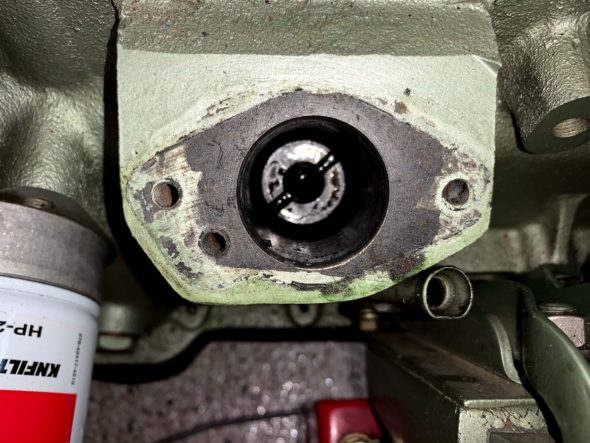
Arm Rest Installed

Arm Rest Installed

Assorted Ignition Modifications

The Original Ignition System

Distributor: Lucas DM6A

Coil: Lucas HA 12 volt

Spark Plugs: Champion UN12Y

Modified Ignition System

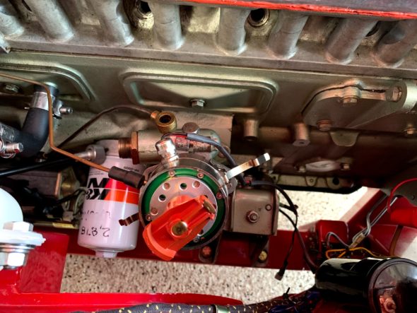
Distributor

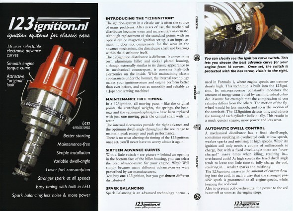
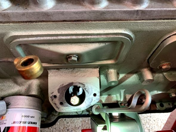
Having converted the Bugeye to electronic ignition with a Crane system, I knew that I wanted to use electronic ignition with the Bloody Beast, but unlike the Crane system, I wanted to use a system that would be housed in the distributor such as a Pertronix. After doing some research I decided to replace the entire distributor with a newly introduced Dutch product, the 123 Distributor. The United States distributer is https://123ignitionusa.com

More information about the installation is provided in this website post: https://valvechatter.com/?p=12431

One appealing aspect of the 123 is that the advance curve is determined by simply adjusting the settings by turning an adjustment on the outside of the distributor and “clicking” it into place. Sixteen curves are available from which to select. Since my purchase the vendor has introduced a programmable bluetooth distributor that can be managed with a laptop. The model number of the unit I used is 123/GB-6-R-V.

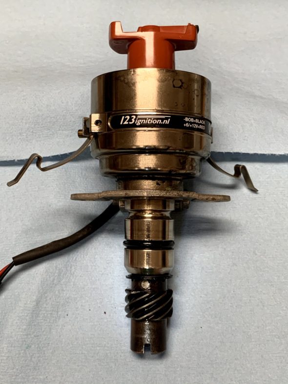
For initial set-up, I chose the recommended “B” setting. While the distributor is a “drop-in” in for the BJ8 with an electronic tach, a kit is supplied to adapt it for the mechanical tach drive of the BT7. The shaft did need to be drilled and the drive dog from the original Lucas unit installed with a few spacing washers. My unit was supplied by a German vendor Brits’N’Pieces.

123 Distributor

123 Distributor

Coil

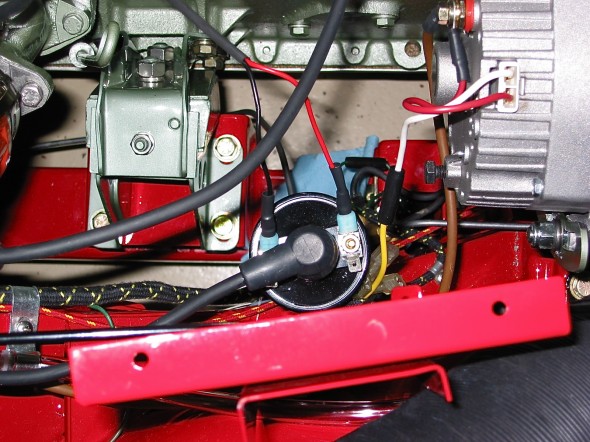
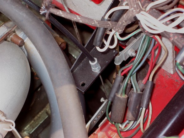
Rather than the original Lucas Coil, or Lucas Sports coil, I decided to go with the Pertronix Flame Thrower Coil in the Bloody Beast. The coil was originally mounted on top of the generator, but since I am using an alternator, that mounting position was not available. I mounted the coil on the vertical upright shroud support post.

Pertronix Flame Thrower Coil

Pertronix Flame Thrower Coil

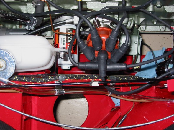
 Ignition Wiring

To complement the Pertronix Flame Thrower Coil, is used Pertronix ignition wiring as well.

Ignition wiring

Ignition wiring


cvcvbvcb

1-2-3 Ignition Installation

I am making this post to provide documentation for others on the subject of 1-2-3 electronic distributors and their installation in Big Healeys. There isn’t too much content regarding the 1-2-3 distributors on the Healey Forums, but I suspect that I am not the only one using this product from the Netherlands. I am not writing this to promote the product or even to encourage others to use it, although I have been very happy with my installation.

I have been using my 1-2-3 since about 2008 though I have never contributed much on the various Forums and bulletin boards about it. A programmable bluetooth unit allowing the owner to to test various advance curves using his/her laptop is now available. However, I purchased mine before that technology was on the market. You can check out their website (or at least the USA marketer) at https://123ignitionusa.com/6-cylinder-lucas-distributors/ for info on the unit I used – 123\GB-6-R-V, or for other models. The unit I purchased has 16 different advance curves. The owner is given parameters for each of the curves and you select the one you want by simply turning a small “click wheel” on the side of the distributor to your choice. In my case I am using the “B” profile.

Click here for the 1-2-3 Installation Instructions and for information regarding the sixteen advance curves.

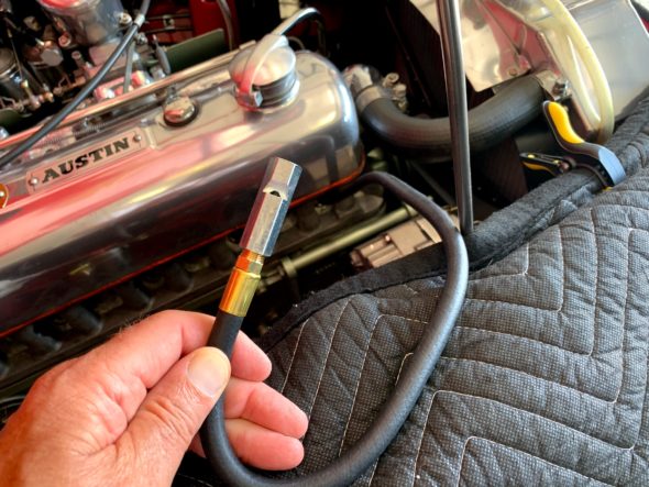
Top Dead Center Whistle Tool

I like to begin the installation process by first getting the #1 cylinder piston at top dead center on the compression stroke. There are a number of ways to accomplish this, but in my case I used a whistle on a hose screwed into the spark plug location for the #1 cylinder.

This is a neat little tool! I removed all of the spark plugs and put the car in fourth gear. I then pulled the car forward. I prefer to pull rather than push because it is much easier to watch the pointer and pulley and to hear the whistle. I passed the point where the timing gear cover pointer and the pulley mark aligned with no whistle, and concluded that the piston was elevated but on the exhaust stroke. I continued to pull the car forward and slowly approached the intersection of the marks a second time. Sure enough, as the pulley mark began to near the pointer the whistle started making its noise. This lasts a little longer than one might think. I stopped when the pointer and the pulley mark aligned again (and the whistle stopped blowing) knowing that I had achieved top dead center on the compression stroke.

The 1-2-3 distributor is not set-up out of the packaging for earlier Healeys with tachometer drives. While the distributor is a “drop-in” in for the BJ8 with an electronic tach, a kit is supplied to adapt it for the mechanical tach drive of the BT7. The shaft did need to be drilled and the drive dog from the original Lucas unit installed with a few spacing washers.

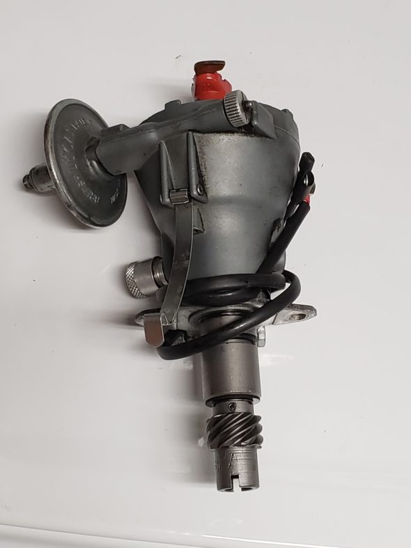
1-2-3 Distributor Rotor Alignment

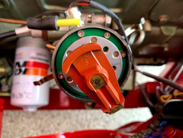
Note that with the shaft lined up identically, the Lucas DM6A rotor is in line with the slot at the bottom of the gear. (Thanks, Steve Gerow for the photo). While the 1-2-3 distributor is clocked 90 degrees out from the Lucas distributor.

Lucas DM6A Distributor

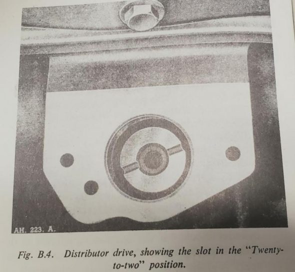
This means that unless one manipulates the distributor driving gear (AEC242) from its original “twenty-to-two” position, the rotor will not point in the 2 o’clock position to approximately the #1 cylinder spark plug when the first cylinder piston is at top dead center on the compression stroke. If you don’t mind that your #1 cylinder spark plug is fed by a lead wire from the distributor’s 5 o’clock terminal then you are ready to go. Simply begin the numbering sequence of 1-5-3-6-2-4 moving counterclockwise for your ignition wires.

1-2-3 5 o’clock Rotor Position

However, If you want your wiring scheme to look “normal,” this can be accomplished quite easily. Note that when you observe the tachometer spindle in the tachometer drive housing the slot in the shaft is not centered. It is offset with the smaller segment in the downward position.

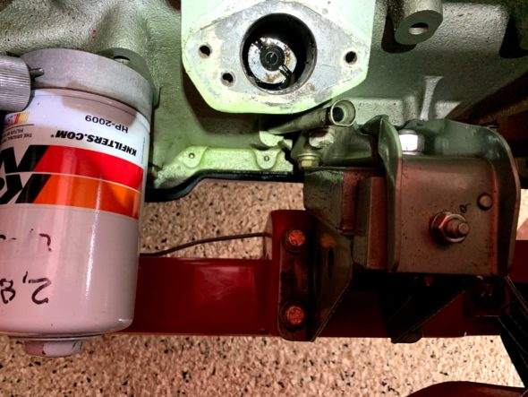
Distributor Drive in the Block

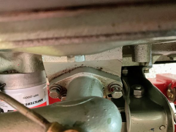
The distributor drive gear is very easy to adjust. Remove the tachometer drive housing by loosening and removing three ¼-28 x ⅞” hex head bolts.

Tachometer Drive Housing Mounting Bolts

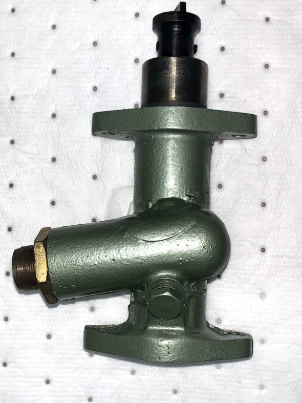
The oil feed banjo and the tachometer cable must be freed from the housing. Then slightly twist and lift away the housing. Then you can give it a fresh coat of paint while it is off the car!

Tachometer Drive Housing

The top of the distributor drive gear is then exposed in its “twenty-to-two” position.

Distributor Drive Gear

Using a 5/16”- 24 x 3 ½” bolt, screw the bolt in a few turns into the center of the drive gear.

Repositioning the Distributor Drive Gear with Bolt

Lift the bolt and the gear up slightly until you can turn the gear and move it to the “ten-to-five” position. It will drop down into position.

Distributor Drive Gear Repositioned to “Ten-to-Five”

Reassemble everything as it was removed. 

If you happened to have turned the shaft in the housing, when you reinstall it make sure that the tachometer spindle is in the correct position with the smaller segment of the offset dog in the downward position. If it is in the wrong position you will find that the distributor will not seat properly. Reinstall the distributor base plate with two ¼”-28 x ½” hex bolts and the distributor.

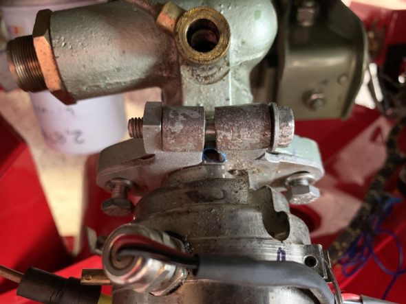
Distributor Bse Plate and Mounting Bolts

With the #1 cylinder at top dead center on the compression stroke the 1-2-3 rotor should now be adjusted to be pointing to the #1 cylinder spark plug at approximately the 2 o’clock position. 

Before placing the cap on the distributor, the 1-2-3 installation instructions state to rotate the distributor body until the distributor wires (black and red) and the vacuum port are in a convenient position for connections. Then connect the red wire to the + terminal on the coil. Leave the black wire disconnected. 

To static time the 1-2-3, turn on the ignition and slowly rotate the body of the distributor and the rotor (to remove any free play) in a clockwise direction until a green LED lights. Then tighten the base plate holding the distributor. Connect the black wire from the distributor to the – terminal on the coil. Attach the ignition wire from the coil to the distributor.

Repositioned Rotor to 2 o’clock

Then install the distributor cap and the ignition wires beginning with the #1 cylinder wire to the distributor cap terminal at the 2 o’clock position (where the rotor is pointed), and then moving counterclockwise connect the other spark plug leads in the prescribed firing order 1-5-3-6-2-4. Attach the ignition cable from the coil to the distributor, and connect the vacuum hose to the distributor. The engine should now start and enable running to get the engine to operating temperature before final ignition timing.

To fine tune the ignition timing with a stroboscope timing light, disconnect the vacuum hose and plug it. Then set your timing in accordance with specifications – in my case, 15 degrees BTDC.  

That should do it. I hope this will be helpful to a Healey owner trying a 1-2-3 distributor for the first time.

Prepared by Lin Rose
July 15, 2020


Assorted Fuel System Modifications

Fuel Pump and Fuel Lines

Fuel Pump and Fuel Lines

The Original Fuel System

The fuel system consists of the fuel tank, the fuel pump, the carburetters and the air cleaners. The original fuel system included the following: Fuel tank: 14.4 U.S. gallon steel tank Fuel pump: SU electric Carburetters: Twin 1 3/4” semi-downdraft HD6 Air Cleaners: Coopers “pancake” type.

 Modified Fuel System

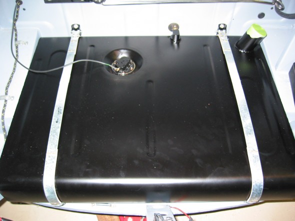
Aluminum Fuel Tank

I replaced the steel tank with an aluminum version sourced from Hemphill’s Healey Haven in Maryland.

Fuel tank aluminum

Aluminum Fule Tank

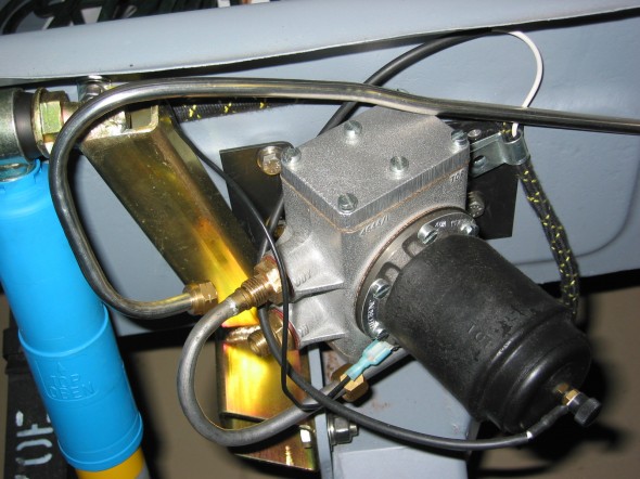
Solid State SU Fuel Pump

I used the original mounting bracket, but replaced the pump with a solid state version of the original fuel pump. The pump was supplied by Burlen in the U.K.

Solid State Fuel Pump

Solid State Fuel Pump

 Redundant Fuel Pump

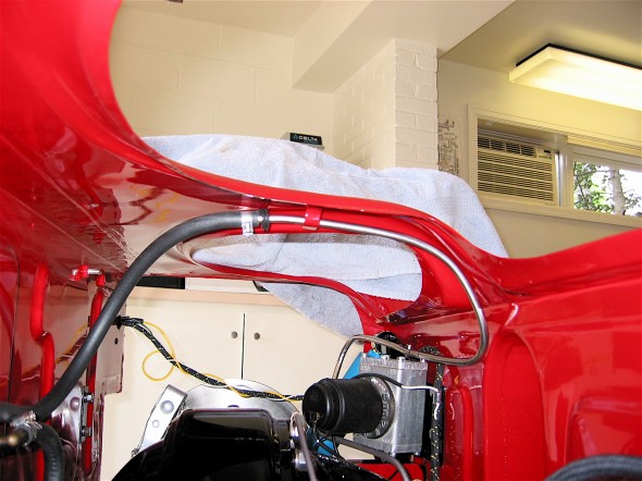
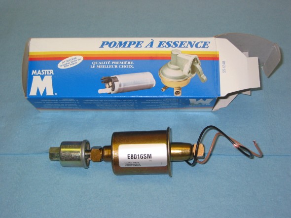
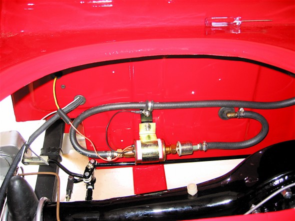
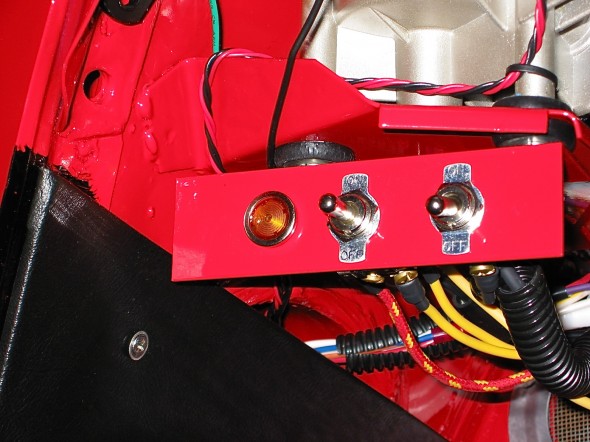
I expected the solid state unit to perform better than the original with its “points,” but I still remember problems with the original pump while I was driving the car in college. I would give it a few good “whacks,” and it would start pumping again. I had read about installing a redundant pump either parallel or in-line to avoid dead fuel pump problems. I mounted the auxiliary pump on the rear boot wall and ran it in-line with the SU. The restoration blog explains the installation. I used a Master E8016S electric pump available from Autozone. I installed a toggle switch on a small switch panel under the wiper motor that controls the fuel pumps. At center, neither pump is activated (a great anti-theft device); a throw upward activates the SU pump, and a throw downward activates the Master Pump. The pumps can be switched on the fly.

Master Fuel Pump

Master Fuel Pump


Aux fuel pump

Auxiliary Fuel Pump Installed

Toggle Switch Panel

Toggle Switch Panel

Fuel Gauge Dampener

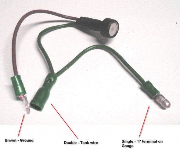
Every Healey owner experiences the erratic swings of the fuel gauge needle. Zims Autotechnik, www.allzim.com , 1804 Reliance Parkway, Bedford, TX 76021, 800-356-2964, sells a little electronic device (see image to the right) that mitigates the needle swing. I believe it was originally conceived for the Porsche 356. Steve Gerow shared this little tip. I ordered one, installed it in a few minutes and sure enough it works! $19.95 for the part. Fuel Gauge Dampener instructions.JPG are provided, but Steve’s photo tells the whole story!

Fuel Gauge Dampener

Fuel Gauge Dampener


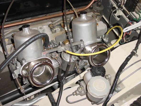
Carburetters

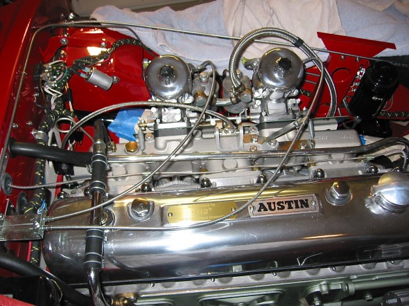
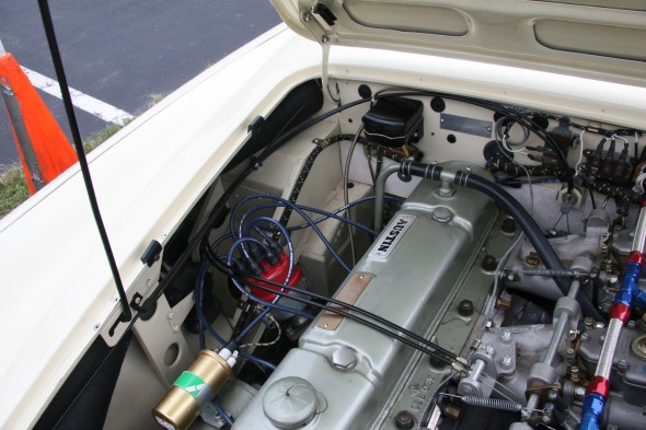
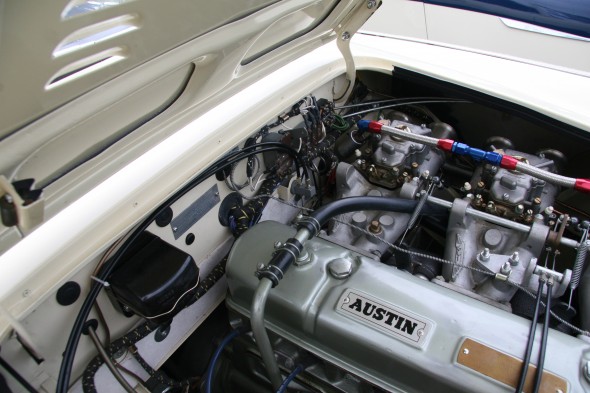
I replaced the original HD6 SU carbs with 2″ HD8s to boost HP a bit. I purchased these from someone on the Healey list and had them rebuilt by Joe Curto. I was pleased with his results. The older used units polished nicely. Using the HD8s did require switching to a later intake manifold from a BJ8 as well, to take advantage of the 2″ diameter carbs.

HD8 Carbs

HD8 Carbs

Carburetter Choke

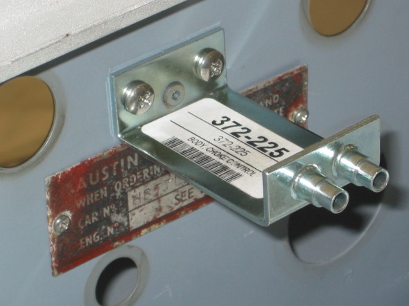
The choke mechanism for the BJ8 carbs is a dual line system as opposed to the single cable used with the original HD6 carbs. So, I ordered the HD8 choke bracket and cabling and installed it in the Bloody Beast.

Choke Firewall Bracket

Choke Firewall Bracket

Air Cleaners

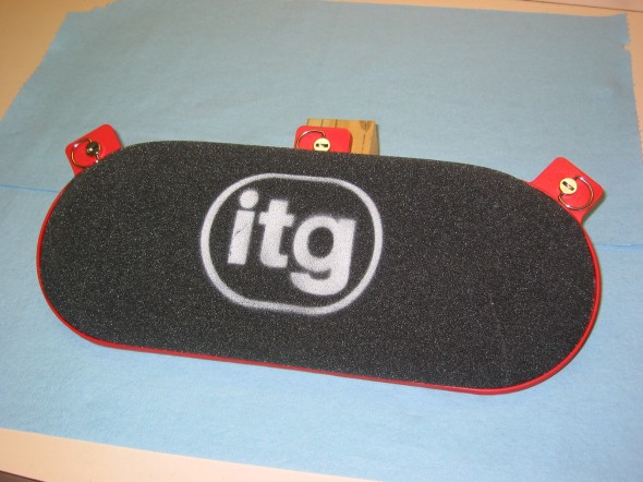
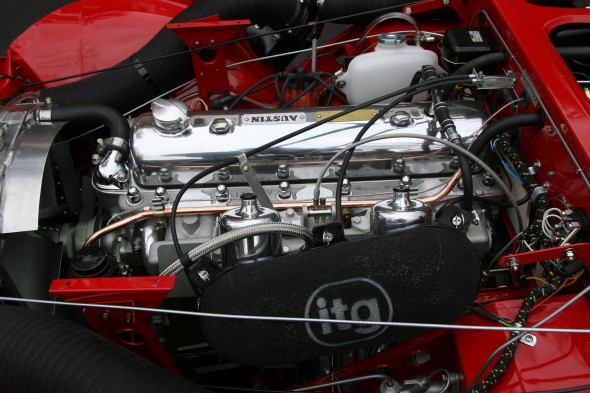
In 2008 when I restored my car, I decided to replace the original pancake Cooper air cleaners and use the “itg” competition foam air cleaner available from Denis Welch. The air cleaner is a single unit working with both carburetors. For appearances, I painted the red plastic body of the air cleaner a gloss black.

However, recently, as part of my “ten-year renewal” process I have moved away from the ITG filter and now use twin ram pipes with individual trumpet filters. This change is explained in this post: https://valvechatter.com/?p=12574

ITG Air Cleaner

ITG Air Cleaner

Aston Quick Release Fuel Filler Cap

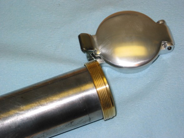
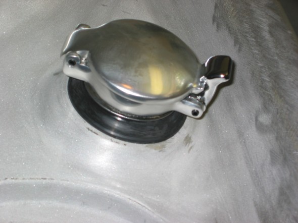
I like the looks of the racing heritage Aston cap that also has its practical ease of use advantage. To install, it is necessary to cut off the original fuel filler pipe and solder a threaded ring onto the pipe. The cap then screws onto the collar. It gives a very nice finish to the fuel system!

Aston threaded collar

Aston threaded collar

Aston Fuel Filler Cap

Aston Fuel Filler Cap


Throttle Cable Modification

Throttle Cable Modification

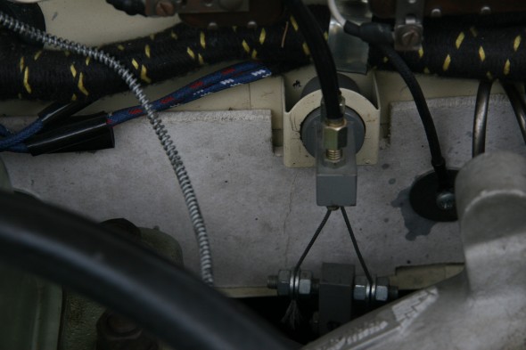
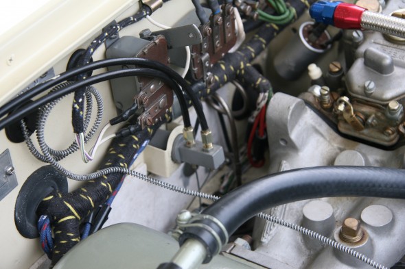
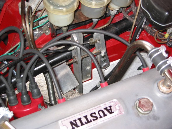
The information below was originally posted in 2009 and modified in 2014. I have since updated how my throttle cable system works (2020) and information on the update is found in a post in my ten-year renewal blog. For example, I no longer us the Denis Welch intake manifold cable bracket. I decided to leave the entry below to provide the reader with history of the progression of this conversion process. This link will direct you to my latest post on the subject. https://valvechatter.com/?p=10123

Owning a Austin-Healey “Bugeye” Sprite always made me wonder about the somewhat arcane mechanical throttle linkage system in my BT7. The Bugeye has a very simple accelerator control system whereby the accelerator pedal and the carburetors are connected via a cable. This provides a direct and immediately responsive system assuming that the carburetor throttle shafts and components are in good condition. Having great respect for DMH and all that he did, I was hesitant to convert my Big Healey accelerator controls to a cable approach. I quizzed all of the Healey experts I could think of, and no one could give me a satisfactory explanation for the mechanical linkage. I suppose the most common response was “the linkage must have been around and used on other cars, so it was cheap to adopt.”

In 2005, my wife and I attended the Conclave held in Winston Salem, NC. There I saw John Trifari’s BN1 that had a throttle cable installation.

John Trifari Throttle Cable 1

John Trifari Throttle Cable 1

John Trifari Throttle Cable 2

John Trifari Throttle Cable 2

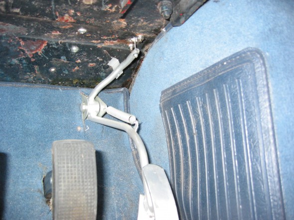
About that same time I was emailing back and forth with Jack Brashear a Healey owner from Arkansas who had also come up with a throttle cable approach to accelerator controls in his Healey. Jack did not modify anything at the accelerator pedal inside the interior, choosing instead to use a modified pedal shaft lever as shown in the image below. I will explain the lever modification a little later in this article. Both John and Jack used a little fitting that I believe came from an MGB through which the cable routes at the top of the driver’s footbox.

Jack Brashear Throttle Cable Install

Jack Brashear Throttle Cable Install

Jack Brashear Throttle Cable Install

Jack Brashear Throttle Cable Install

Also in 2005, I attended several of the races in the Australian/U.S. Healey Challenge series. Many of the Aussie’s cars had throttle cables instead of the mechanical linkage. Of course, the Australian cars are RH drive so the design is somewhat different (actually easier) than for LH drive cars. I noticed too that the Australian cars almost always incorporated some type of throttle stop mechanism. I suppose especially important in a race car.

Australian Racer with Throttle Cable and Throttle Stop

Australian Racer with Throttle Cable and Throttle Stop

These examples and others that I came across about the same time convinced me that the use of a cable to control accelerator action to the carburetors was the approach that I wanted to take. However, everything that I had witnessed first hand was typically one-off, and custom designed, and I wondered if there was an easier route to my end game. I started checking vendors.

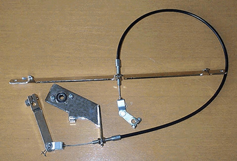
Cape International had a conversion kit http://www.cape-international.com/capeshop.php?parttypes=19&thepart=TC2# I actually tried this kit but wasn’t thrilled with it. I am sure it has been installed successfully in many cars, it just wasn’t my cup of tea.

Cape International Throttle Cable Kit

DMD from Australia also made a conversion kit. It is now available (as of August, 2014) from The Healey Factory. http://www.healeyfactory.com.au/dmd/components/ I did not personally try the DMD kit.

The Healey Factory DMD Throttle Cable Kit

I began to work on my own throttle cable kit using ideas I had seen on other cars or in the kits available from the vendors named. The narrative that follows chronicles my installation. It does not describe a right or wrong approach – it is just my approach. In fact, I am sure that others can improve upon my design. Comments and suggestions are certainly welcome.

Installation Disclaimer

Accelerator Pedal Swing Arm Lever

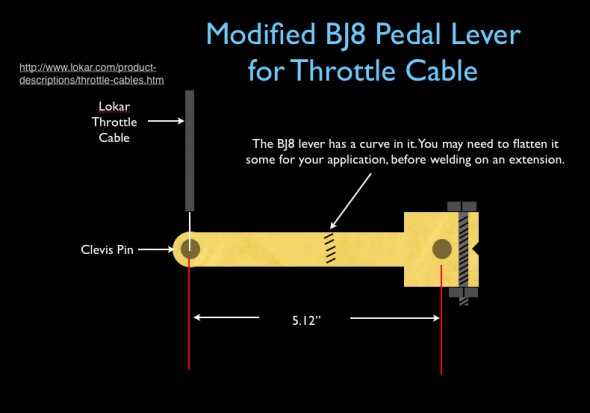
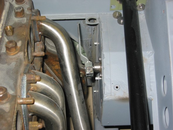
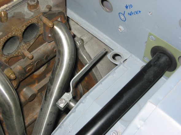
I decided to modify the throttle swing arm lever used on a BJ8 to suit my needs. I like this one better than the BT7 swing arm as it is a bit more substantial and in my view seemed a little less likely to slip on the pedal shaft once tightened. I have now used this arrangement since 2009 including an 8,000 mile cross-country trip without any problems. Jack Brashear suggested lengthening the arm so that it would swing perfectly in line with the firewall cable bracket and I followed his lead.  I have headers on my car and a Toyota Supra Five-speed (not overdrive components on the firewall) so if the reader is planning a modification to the lever just make sure you have sufficient room.  The following diagram illustrates the modification:

Throttle Swing Arm Lever Modification

Throttle Swing Arm Lever Modification


Rose Throttle lever modified 1

Rose Throttle lever modified 1

Rose Throttle lever modified 2

Rose Throttle lever modified 2

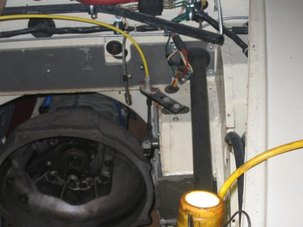
Firewall Bracket

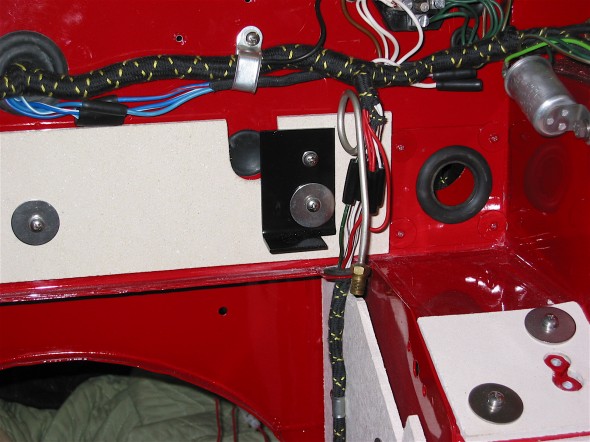
I then made an “L” shaped bracket to mount to the firewall.  I used the welded nut on the firewall (see above) for one of the securing points and drilled a hole for a nut cert for the top securing point. My final bracket looks slightly different than this one, but this is the best image I have to illustrate the mounting of the bracket to the firewall – note that it mounts through the firewall insulation panel.

Rose Firewall Throttle Bracket Version 1 - Not Final

Rose Firewall Throttle Bracket Version 1 – Not Final

The image below is not from my car but it shows a bracket similar to mine mounted on the firewall. I apologize that I do not know who owns this car. I just snapped the image at a show.

Firewall Throttle Cable Bracket - Unknown Owner

Firewall Throttle Cable Bracket – Unknown Owner

The following image is of my car and shows the relationship between the swing arm lever and the firewall bracket with the cable.

Relationship of Swing Arm Lever to Firewall Bracket and Cable

Relationship of Swing Arm Lever to Firewall Bracket and Cable


Carburator/Manifold Bracket

I tried numerous approaches to fabricating a bracket to get the cable to the right place to control the carburetor throttle shaft lever. You must decide if you want the cable to run down from the firewall, below the carbs, and up to the carburetor throttle shaft lever, or alternatively, do you want the cable to run up and over the carbs and manifolds? With my approach I chose to have it do the latter. It can be done either way.

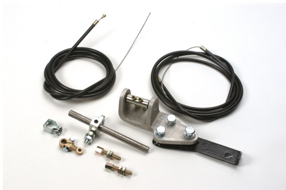
About the time I was trying to figure all of this out, Denis Welch came out with a LH drive throttle cable conversion kit that in my view is very well done. It contains a cast aluminum bracket that bolts to the intake manifold and runs a double cable from the pedal lever to the carburetor’s throttle shaft.

http://www.bighealey.co.uk/content/throttle-cable-conversion

Denis Welch Throttle Cable Kit

Denis Welch Throttle Cable Kit

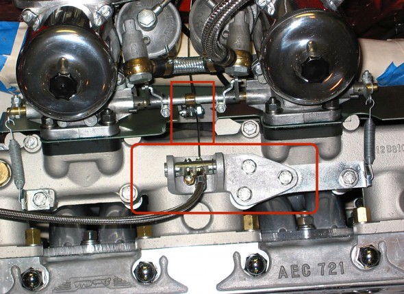
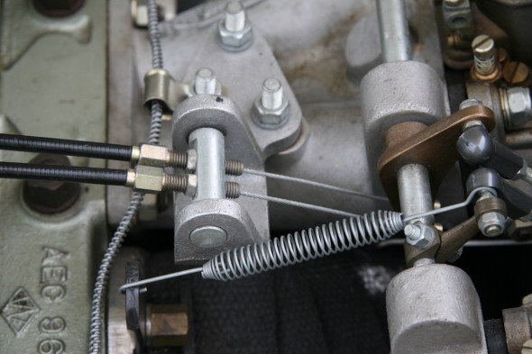
Because I had already begun my work and had my firewall bracket in place I decided to use the Welch cast aluminum bracket for my car, but not the rest of the kit. It has a swing mechanism built into to the cable housing that takes all alignment pressure off the cable. The kit is designed for racing cars and as such has a double cable. The double cable probably provides a somewhat smoother action and some security. I only use one cable, but I will probably switch to two at some point.

Approaching the carburetor throttle shaft lever from the manifold side of the carbs means you are pulling the carburetor throttle shaft lever up and there is not a great deal of room for that swing. I ended up cutting a notch out of my heat shield to remove any encumbrances. The image below shows the Denis Welch manifold-mounted bracket and the cut-out in the heat shield.

Welch Throttle Bracket

Welch Throttle Bracket

The Cable

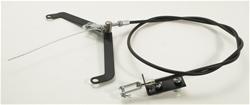
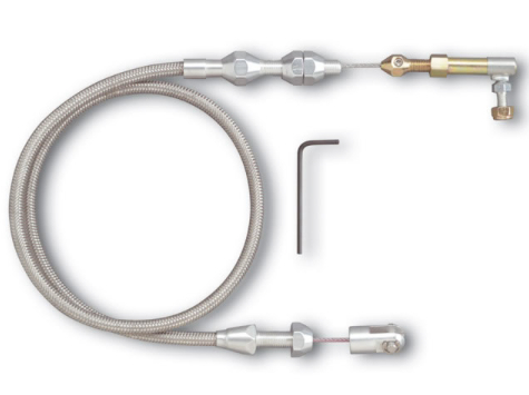
The kits provide cable and fittings. I decided to use a Lokar cable and fittings only because I liked the braided cable appearance in the engine bay. Other’s may prefer black and in fact, Lokar now makes this same cable in black with black fittings. http://www.lokar.com/product-pgs/throttlecables-kickdowns/tc-kd-pgs/throttle-cables.html

Lokar Throttle Cable

Lokar Throttle Cable

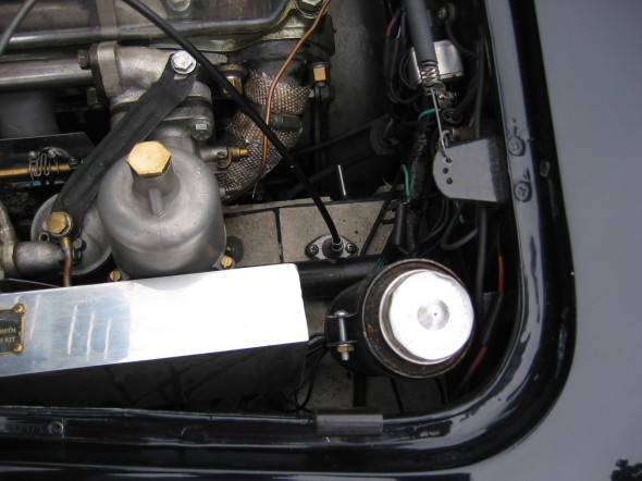
The Total Package

This image shows the engine bay with the throttle cable installed. I now run a stainless heater pipe rather than the copper, and my fuel hose routes differently on the front carburetor, but other than that things today are pretty much what you see in this image.

I cannot make meaningful comparisons between the functionality of the original throttle linkage and the new throttle cable. My mechanical linkage was fifty years old and worn out so comparisons are not appropriate. I do know that the cable has worked quite well, is very responsive, and much easier to get to than the original mechanical system.

My Bloody Beast Engine with Throttle Cable

My Bloody Beast Engine with Throttle Cable

Another’s Installation

I don’t know who owns the car, but I recently came across some images of a throttle cable conversion that is accomplished quite well in my view. There is a long cable run, but it is well executed. This car uses Webers instead of SUs but the approach is the same. Apologies to the owner if he/she is unhappy sharing this nice work:

Throttle Cable Routing

Throttle Cable Routing

Throttle Cable Routing

Throttle Cable Routing

Manifold Mounting

Firewall Mounting

Firewall Mounting

I hope this description has been useful to readers who are interested in taking a similar approach. Just as I borrowed from the work of others and modified to my own tastes I would expect others to do the same. Please comment, offer suggestions as you like.

While the article does not format as well in a pdf document. for those readers who want to save this as a pdf or for those who want to print it as a pdf, this is the link:Throttle Cable Modification – Valve Chatter


Exhaust System

Exhaust

The Original Exhaust System

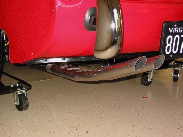
The exhaust system consisted of two exhaust manifolds connected to the silencer by two downpipes ending with flex tubing. A dual tailpipe assembly was used exiting on the left rear of the vehicle.

Exhaust System Modifications

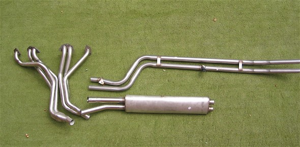
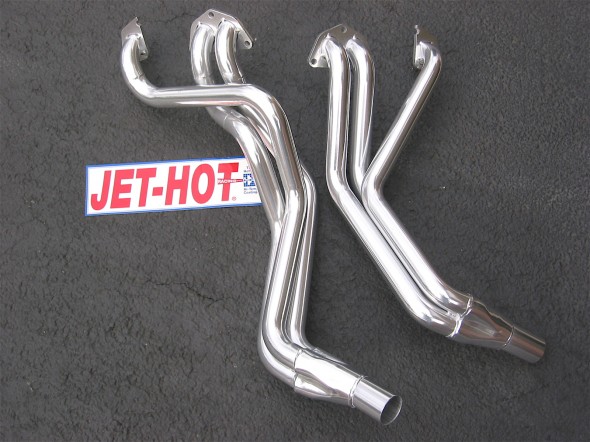
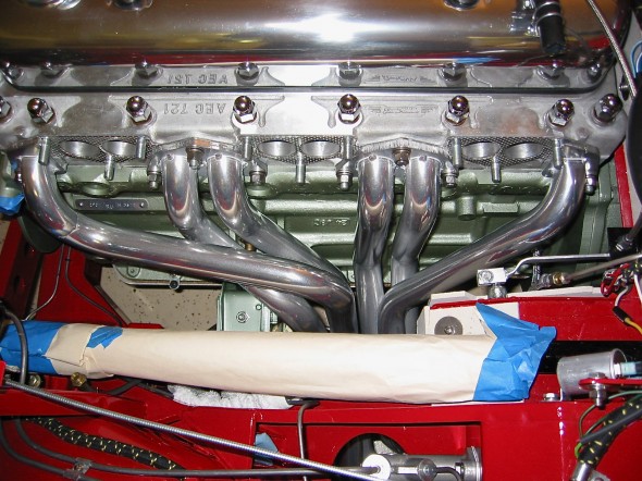
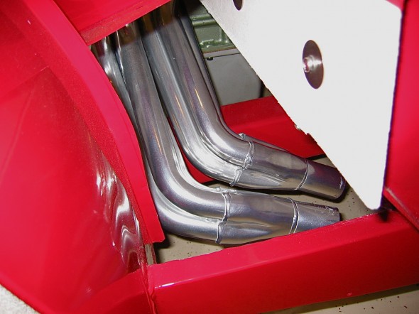
I replaced the standard exhaust system with a Phoenix Big Bore 2″ stainless steel exhaust pipe, silencer, and long branch headers. The headers were Jet-Hot ceramic thermal coated to keep them looking good and to reduce heat.

The system consists of the clutch, gearbox, overdrive, and propshaft. The original driveline system included the following:   Clutch: 10” Borg and Beck hydraulic Gearbox: “side-shift” 4 speed Overdrive: Laycock de Normanville electric Propshaft: Hardy Spicer universal joints Flywheel: 28 lb.

Jet-Hot Headers

Phoenix Headers

Phoenix Headers

Phoenix Headers Installed

Phoenix Headers Installed

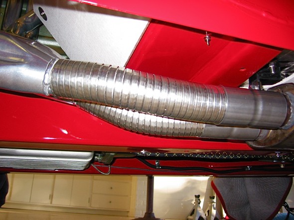
I used flexible stainless pipe to link the headers to the silencer.

Flex Pipes

Flex Pipes

2" Big Bore Stainless Pipes

2″ Big Bore Stainless Pipes

zz