Away for travel


Away for travel
With a little help from a work colleague, my wife and an engine hoist I was able to get the motor with bell housing into the car without one scratch or knick in the paint! We took our time and patience paid off. I tightened down the engine mounts and then put a short jack stand under the bell housing to support the rear of the engine.
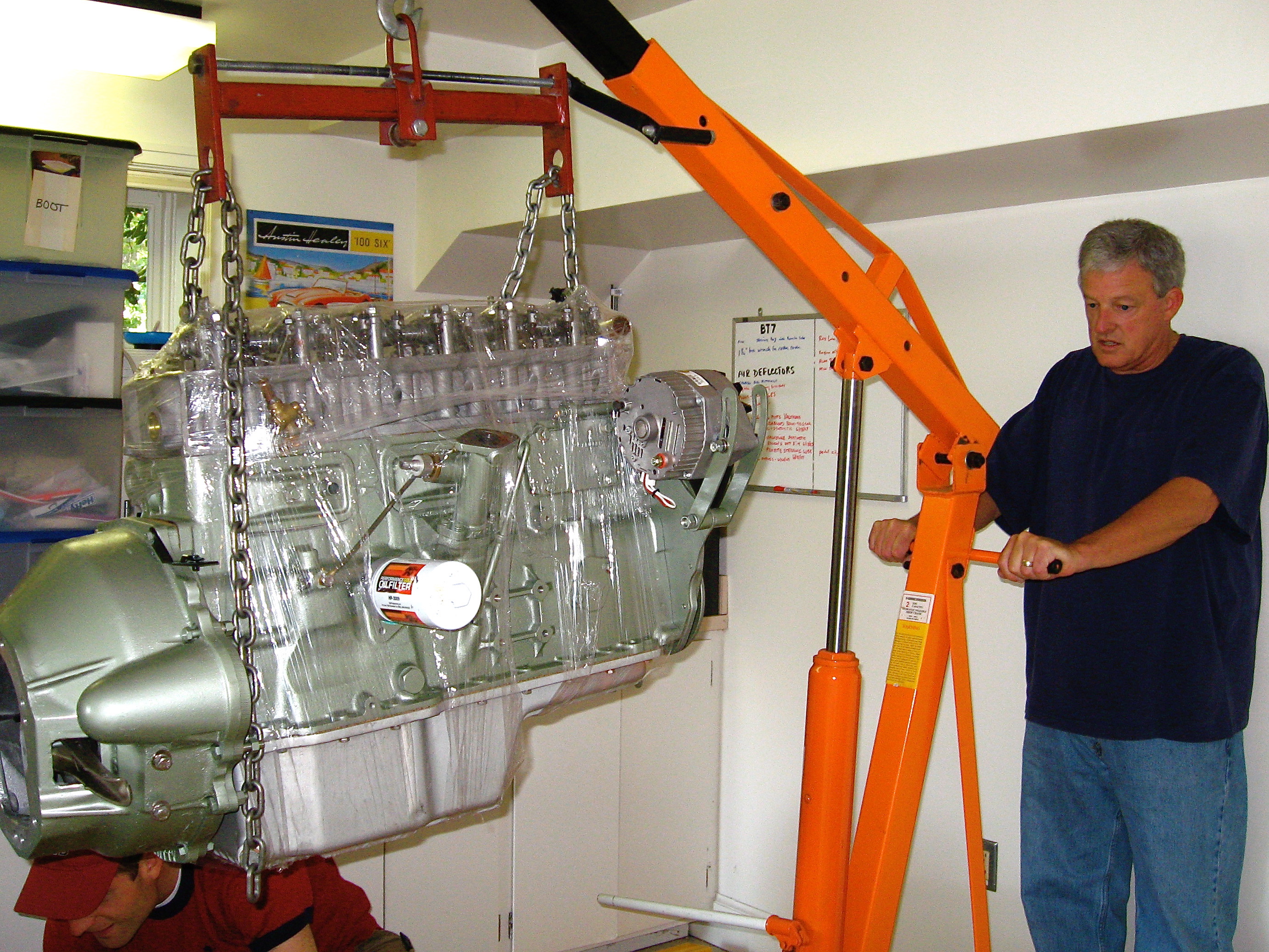
Engine Hoist
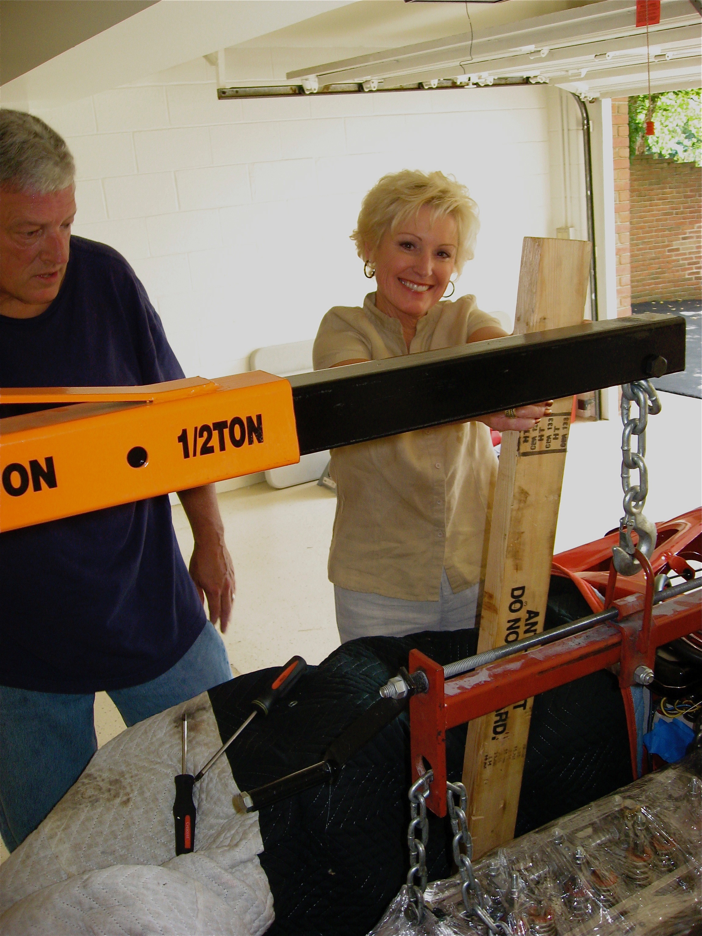
Helper One
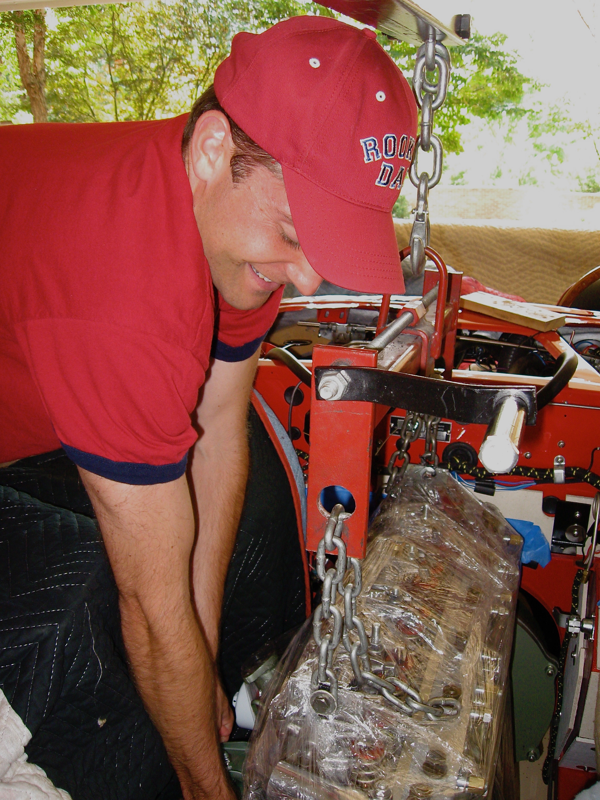
Helper 2
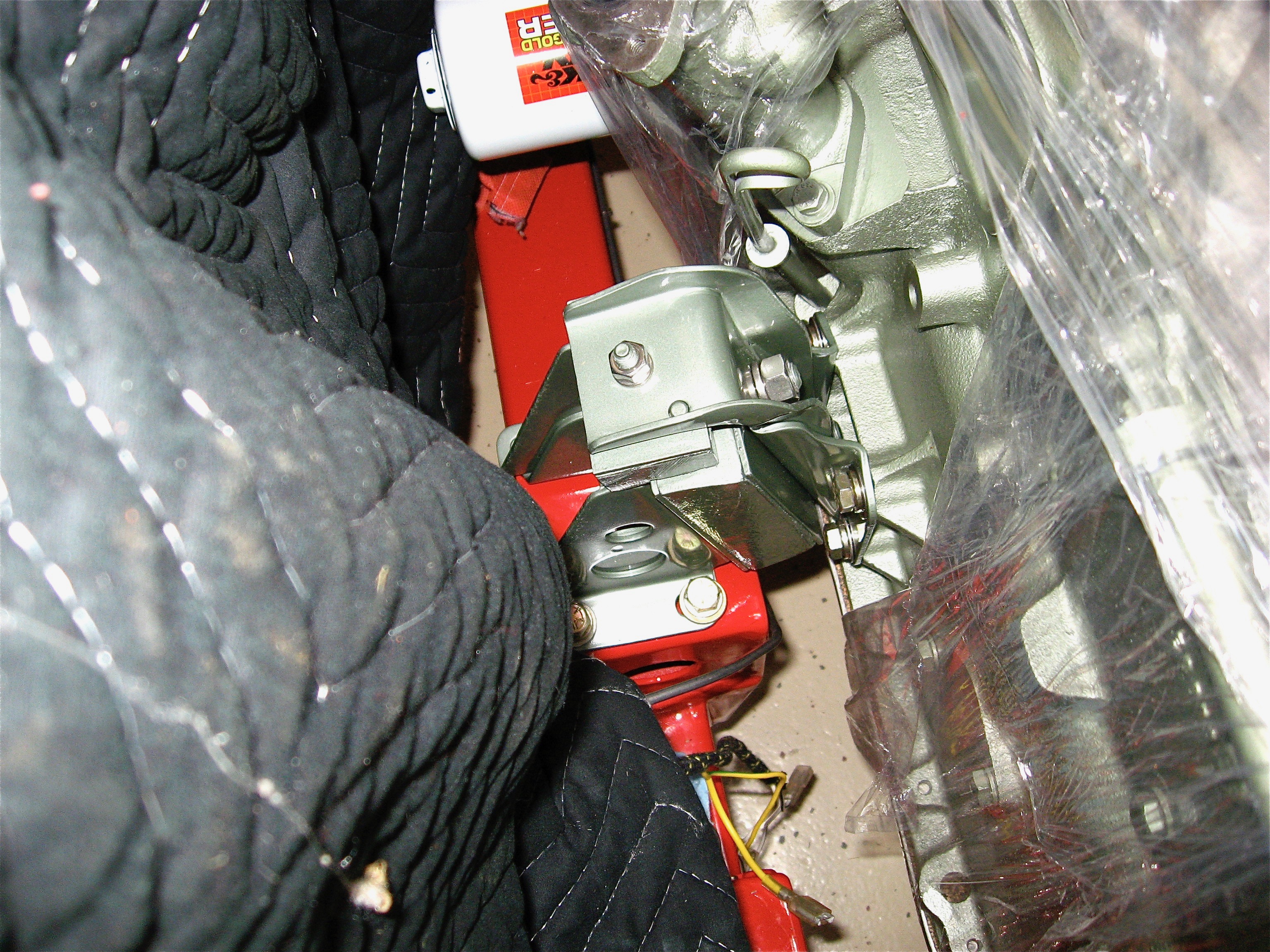
Motor mount tightened down
I had previously bled the slave cylinder so it was an easy task to mount it to the side of the bell housing, insert the Smitty provided push rod, and try out the mechanism by pushing the clutch pedal. The longer fulcrum pin I had made (with directions from Tracy Drummond) worked perfectly. Special thanks to my engine installation assistants – couldn’t have done the job without them.
I did take a minute to install the engine identification number plate on the engine block. I had a new one made by Clarke Spares & Restorations and it looks very authentic.
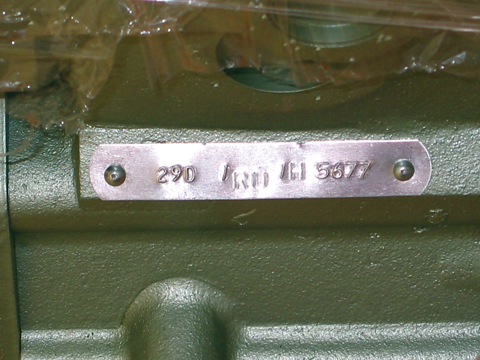
Engine Number Plate
I am going out of the country for two weeks so things will have to sit a while until I return and get back to work. The next step will be to pull the engine back out, attach the gearbox to the bell housing, fasten the assembly to the engine and put it all back in the car. I suppose I could have skipped the clutch test, but what are a few more hours in a six year restoration!
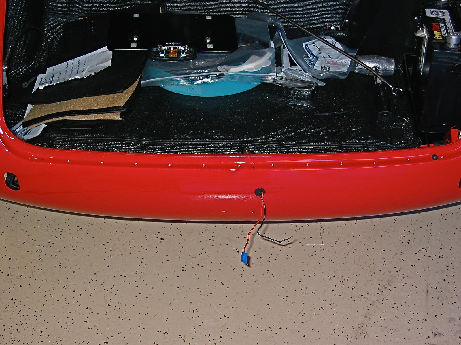
The next job to be tackled was the installation of the rivets for the rear shroud to the frame. There are 19 aluminum flush face rivets for the lower lip of the car and another 13 rivets that attach the shroud to the rear boot frame rail.
First, I put a healthy bead of 3M body caulk between the two pieces to keep water out of the boot. I clamped things together as best I could and inserted pop rivets in the frame rail just to line the components up properly. The aluminum rivets for the lower lip were sourced from British Car Specialists. I purchased a rivet squeezer tool from Brown Aviation Tools with the 2003-16 1/8” rivet set to use for the job. An expensive tool at $135 for one little job! The tool worked nicely. After an initial “squeeze” with the tool, I put five small #10 washers on the rivet set to pull them closer together and squeezed the rivet again. I ended up with a very satisfactory job. As per original specifications, I then painted the lower lip satin black.
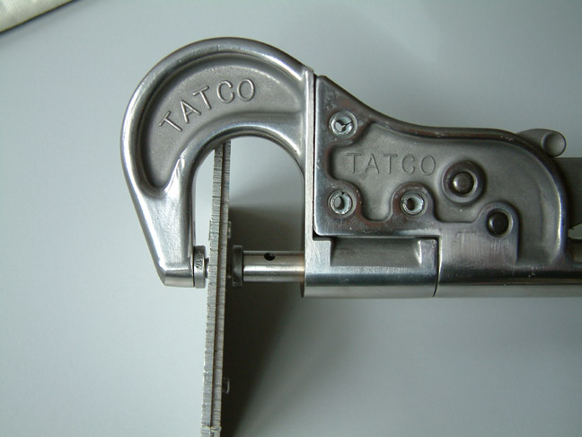
Rivet Squeezer
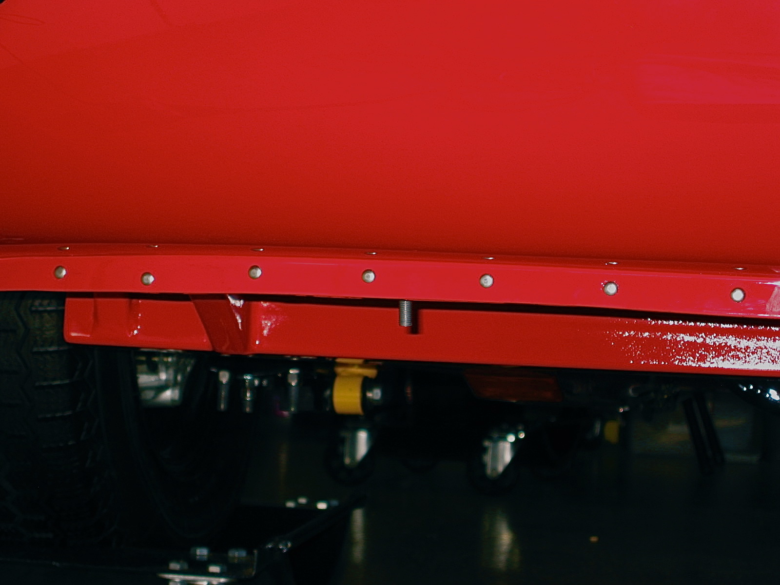
Lower Rivets installed
There just wasn’t room to use the rivet squeezer for the boot rail-to-shroud assembly so I used 1/8” diameter, 1/4” long aluminum pop rivets for the job. The nose of the rivet gun wanted to hit the boot lip so I put about three thicknesses of blue painter’s masking tape around the area to protect the paint. I did get two small nicks that were touched up, but otherwise the project was a success. It pays to take your time on the rivet job if you are assembling after painting.
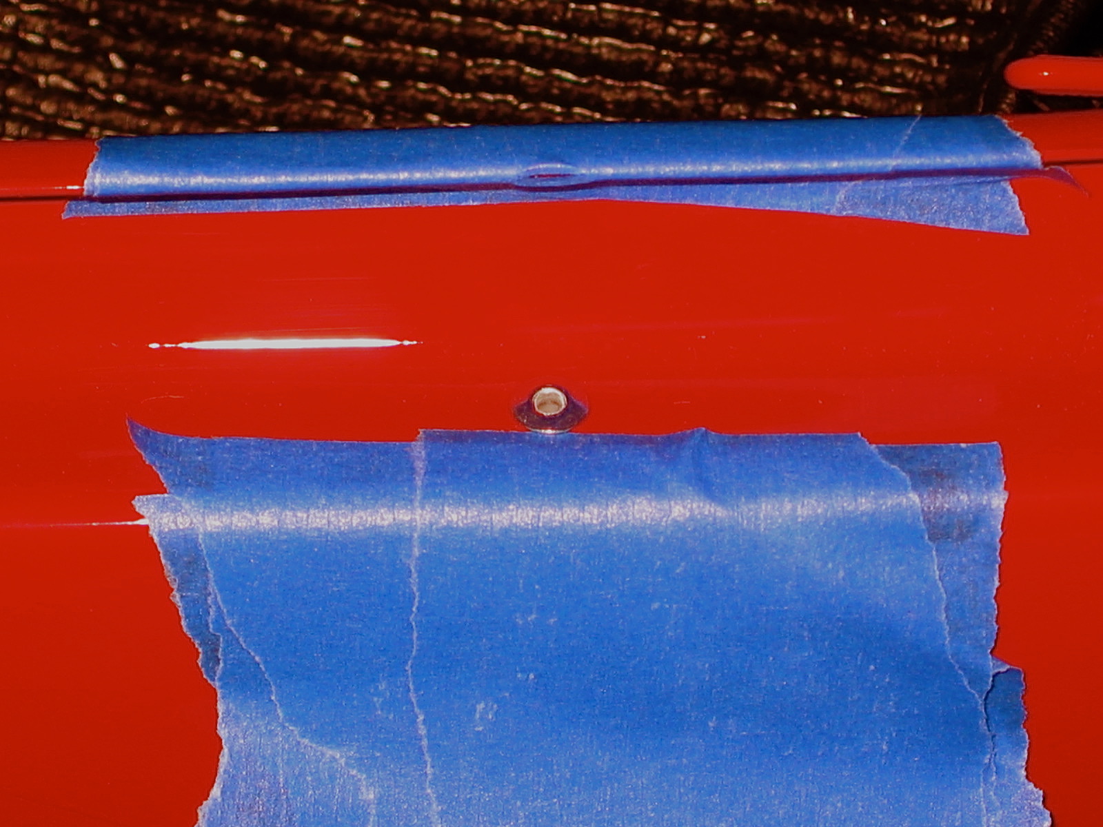
Rivet paint protection
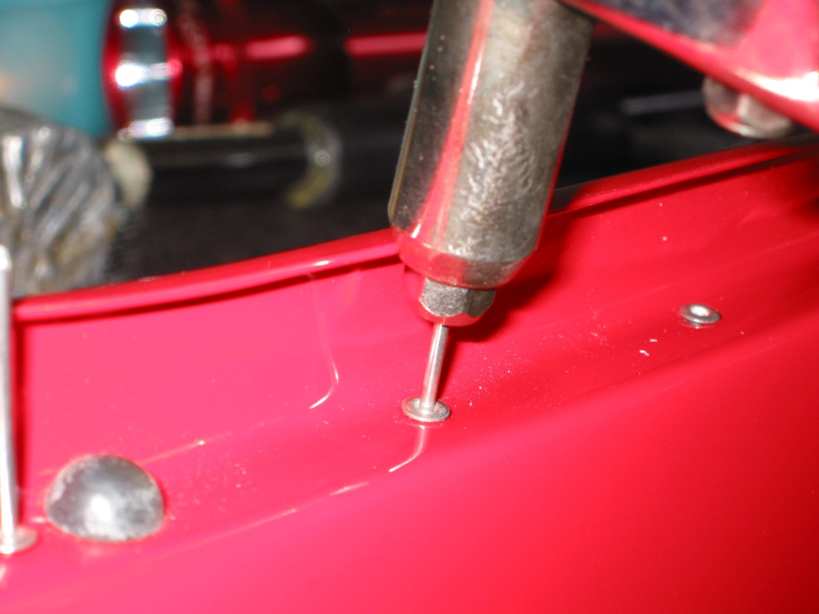
Pop Riveter
Pop Rivets installed
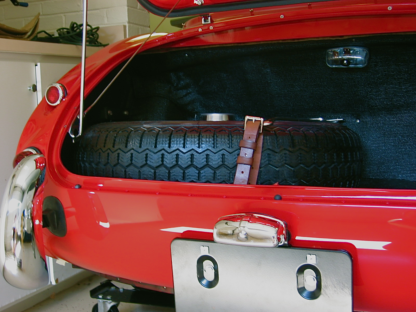
Following the rivet work I installed the rear bumper bars and rally bumpers supplied by Cape International. New rubber grommet seals were installed on each bar, paying attention to the LH/RH designation. I am very pleased with the look of the rally bumpers, although one is not afforded much protection by these full bumper replacements!
Rally Bumpers
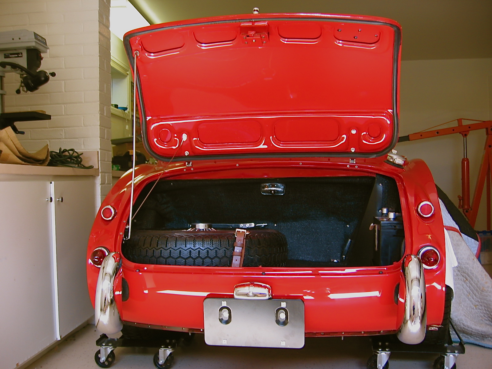
The next task was to install the boot lid. This turned out to be pretty easy. Again I protected the body with some blue painter’s masking tape and with the help of my wife, put the lid in place and tightened down the boot hinges. After getting the lid in place, I needed to adjust the boot lid striker so that it would fit properly to latch the boot lid. I then attached the boot lid control cable to the lower hinge post and I was in business!

Boot Lid Installed 2
Back End Finished
Before the final installation of the engine, I decided to fit the clutch assembly and Smitty Bellhousing to the block and put in the car to make sure the clutch was working properly. I wanted to make sure that I had sufficient room for the clutch fork to function once connected to the slave cylinder. Some might call this a little anal, but if you install with just the bellhousing and not the gearbox, you can view everything to ensure success later!
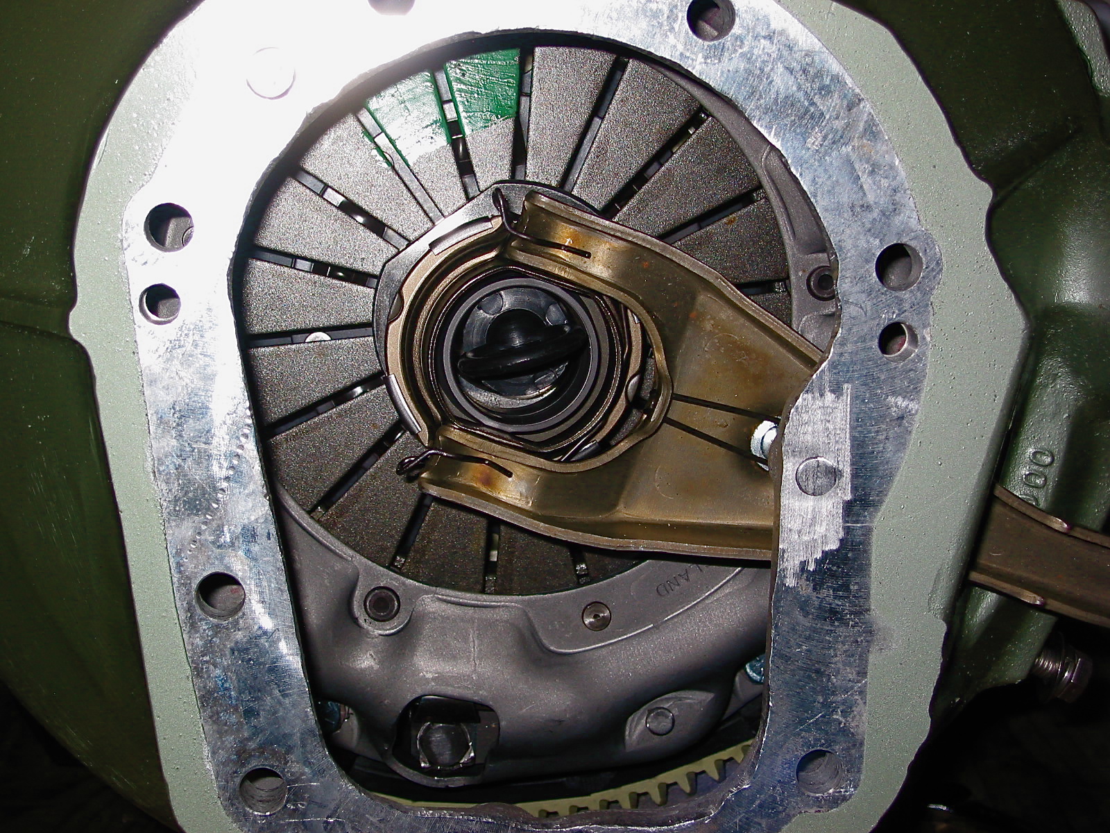
Clutch Fork 1
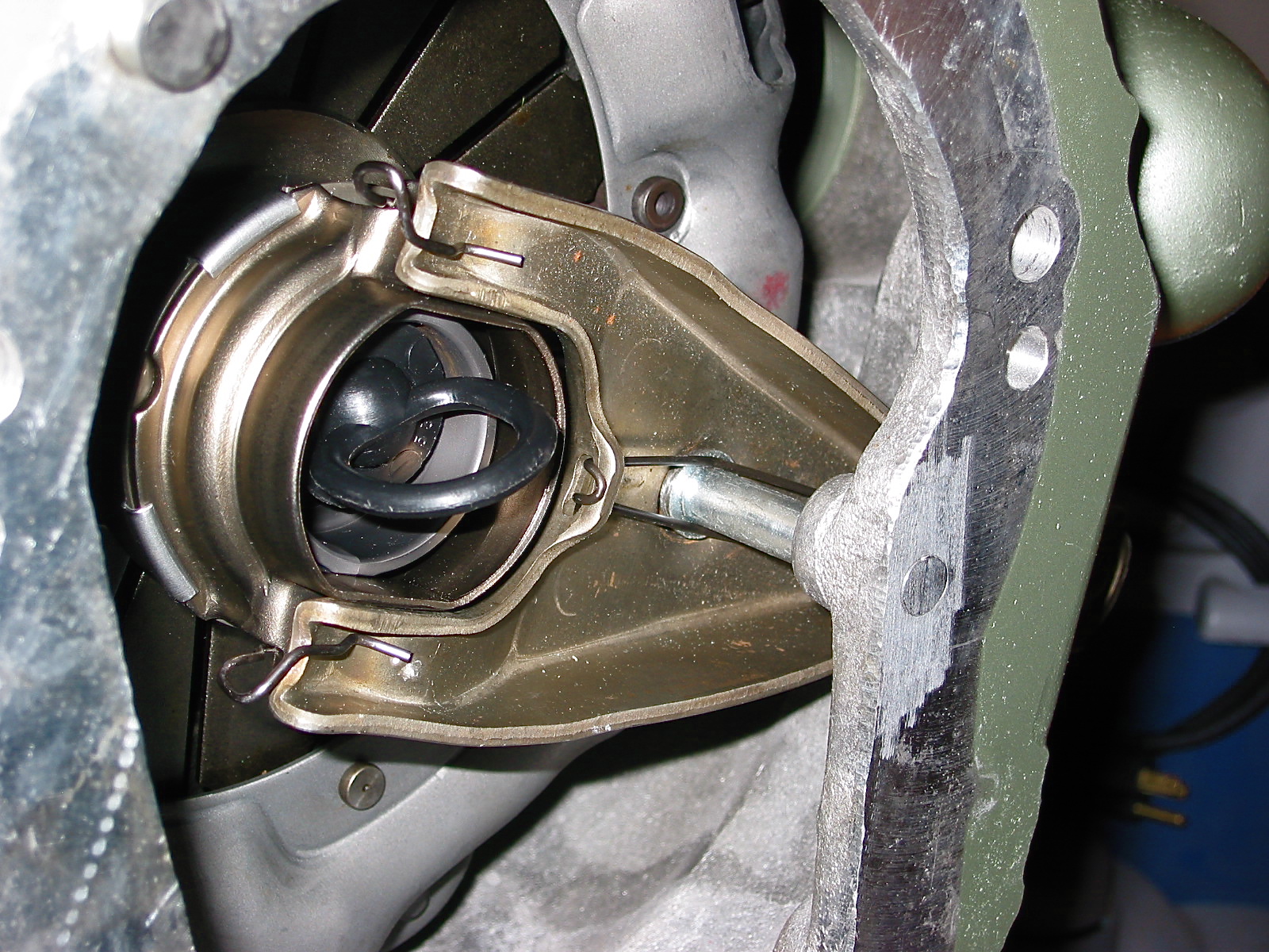
Clutch Fork 2
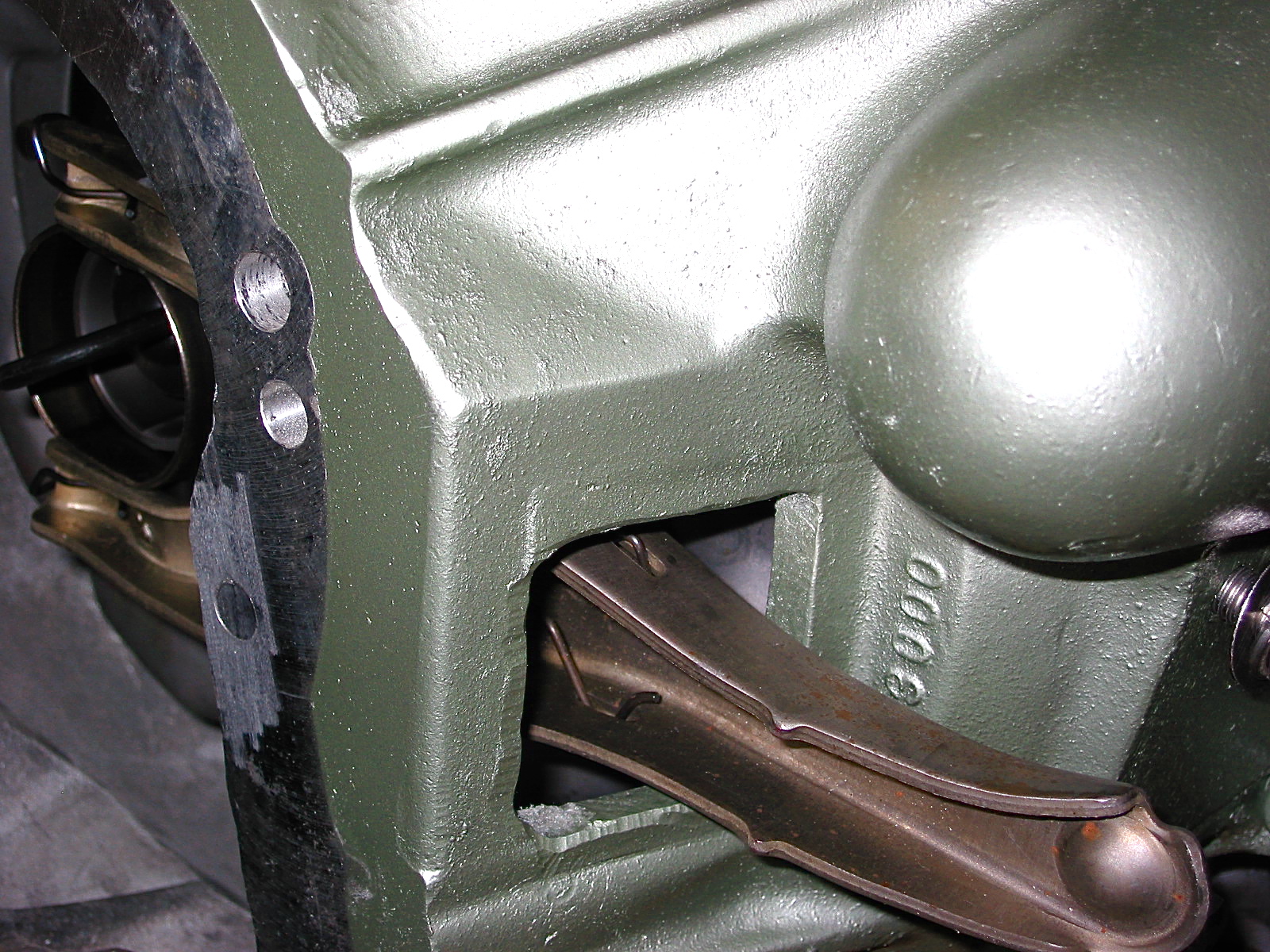
Clutch Fork 3
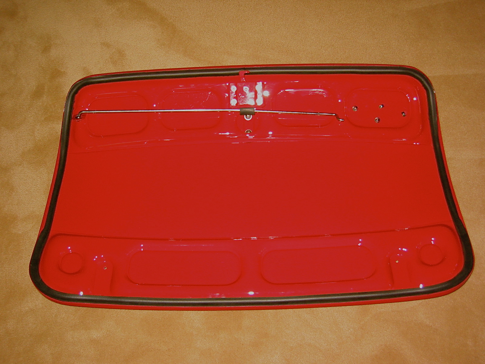
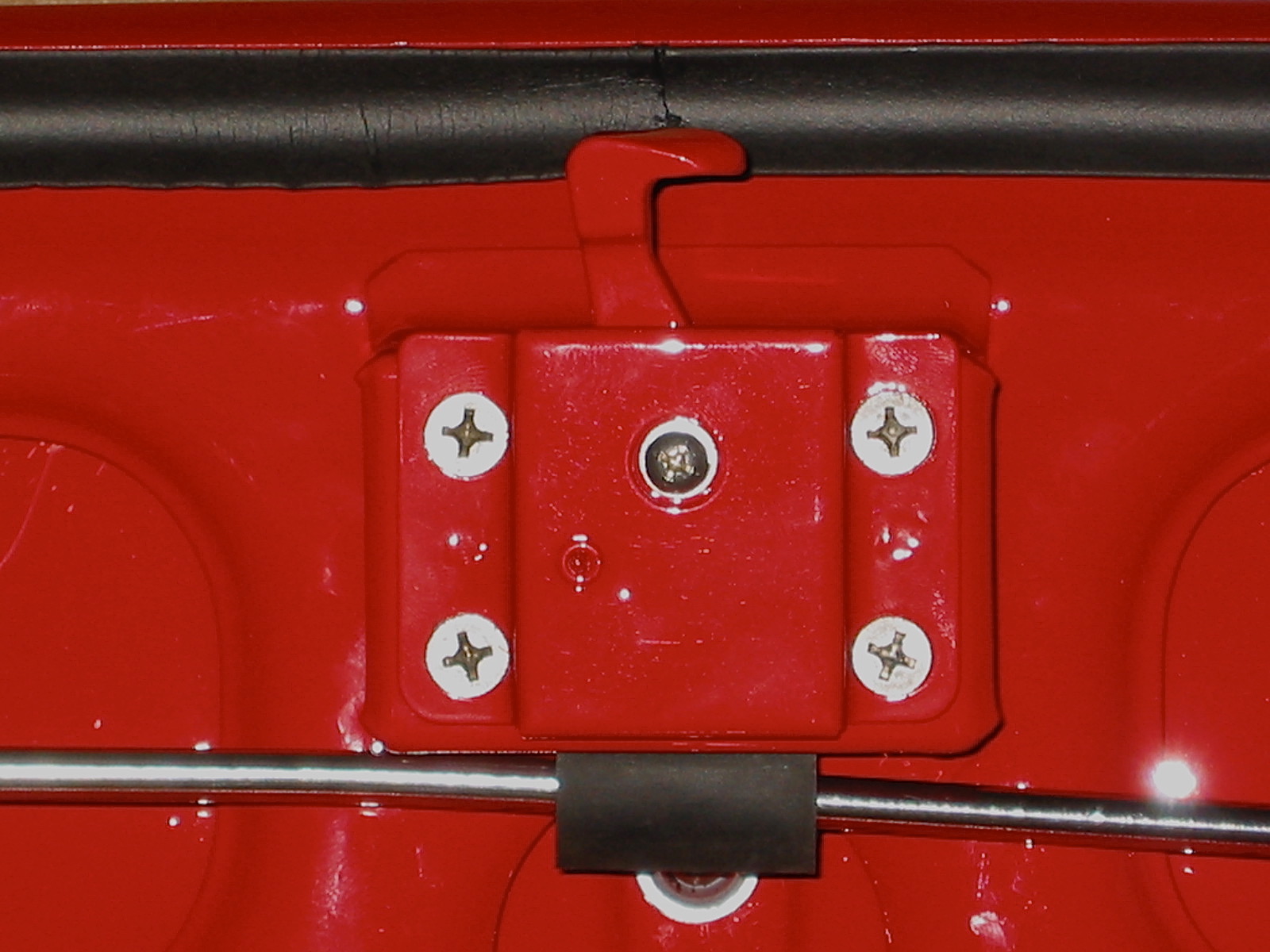
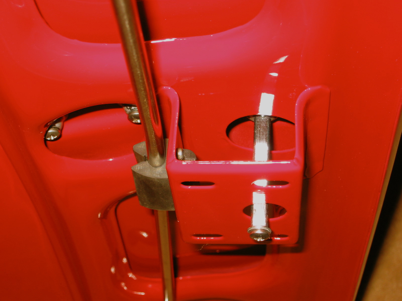
Since I am using rally bumpers on the “Bloody Beast” rather than the standard rear bumper, I needed to develop a custom rear license plate bracket. I combined the stock bracket with a later BJ8 bracket that provides a space for the Lucas license plate lamp. All of this was a little heavy to hang on just the two holes in the rear of the aluminum shroud, so I fabricated a small steel plate to mount inside the shroud and sandwiched the shroud with two homemade gaskets of 1/16” black rubber. The assembly looks nice and I think provides a satisfactory solution given the lack of a bumper on which to mount it.

License Plate Bracket 1
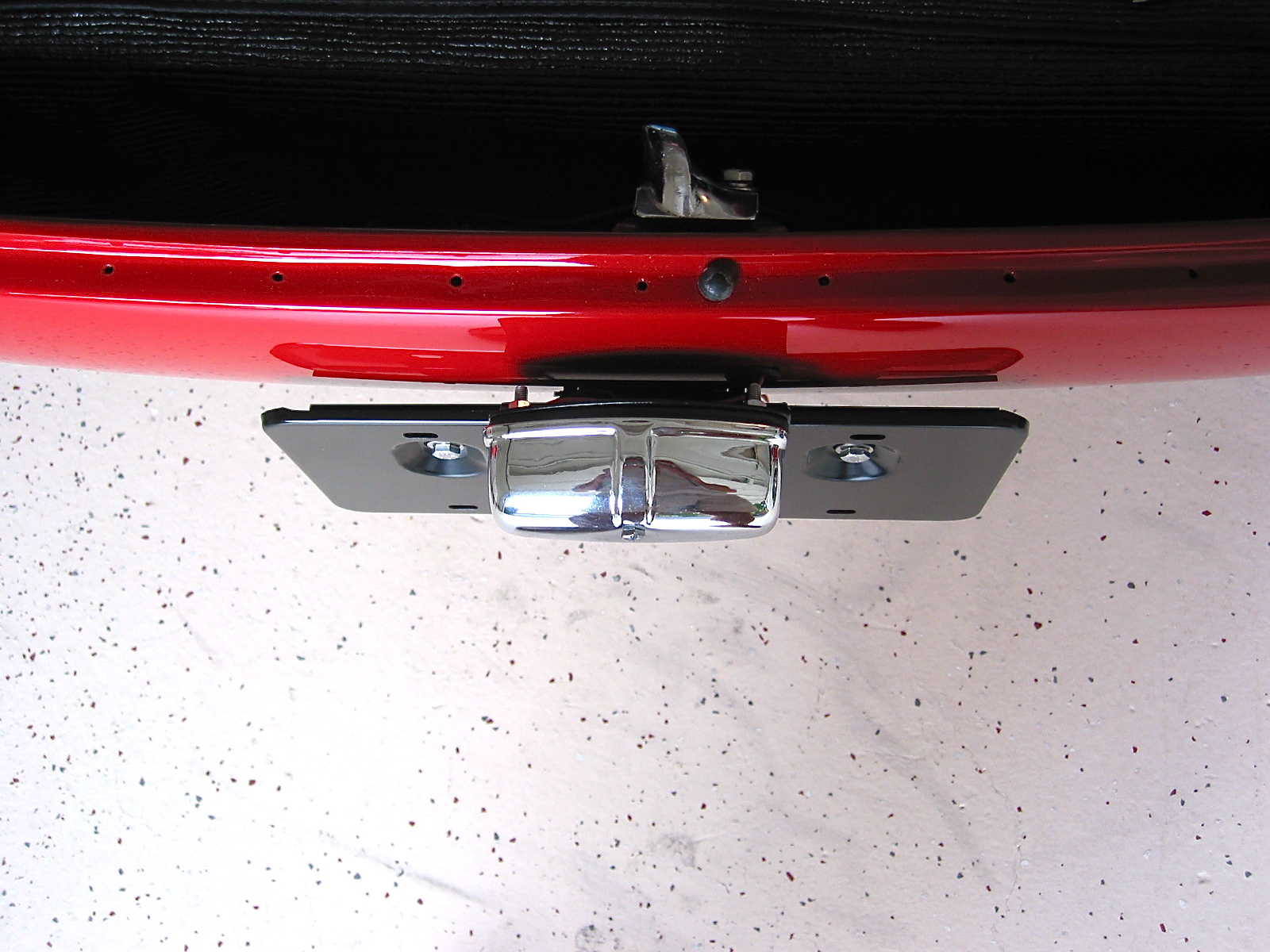
License Plate Bracket 3
Having taken the car off the wooden dollies I had made to transport it from my home to Maple Hill Restoration, I was able to get to the lower part of the front suspension and install the Cape International 3/4” anti-sway bar.

Anti-Sway Bar hardware
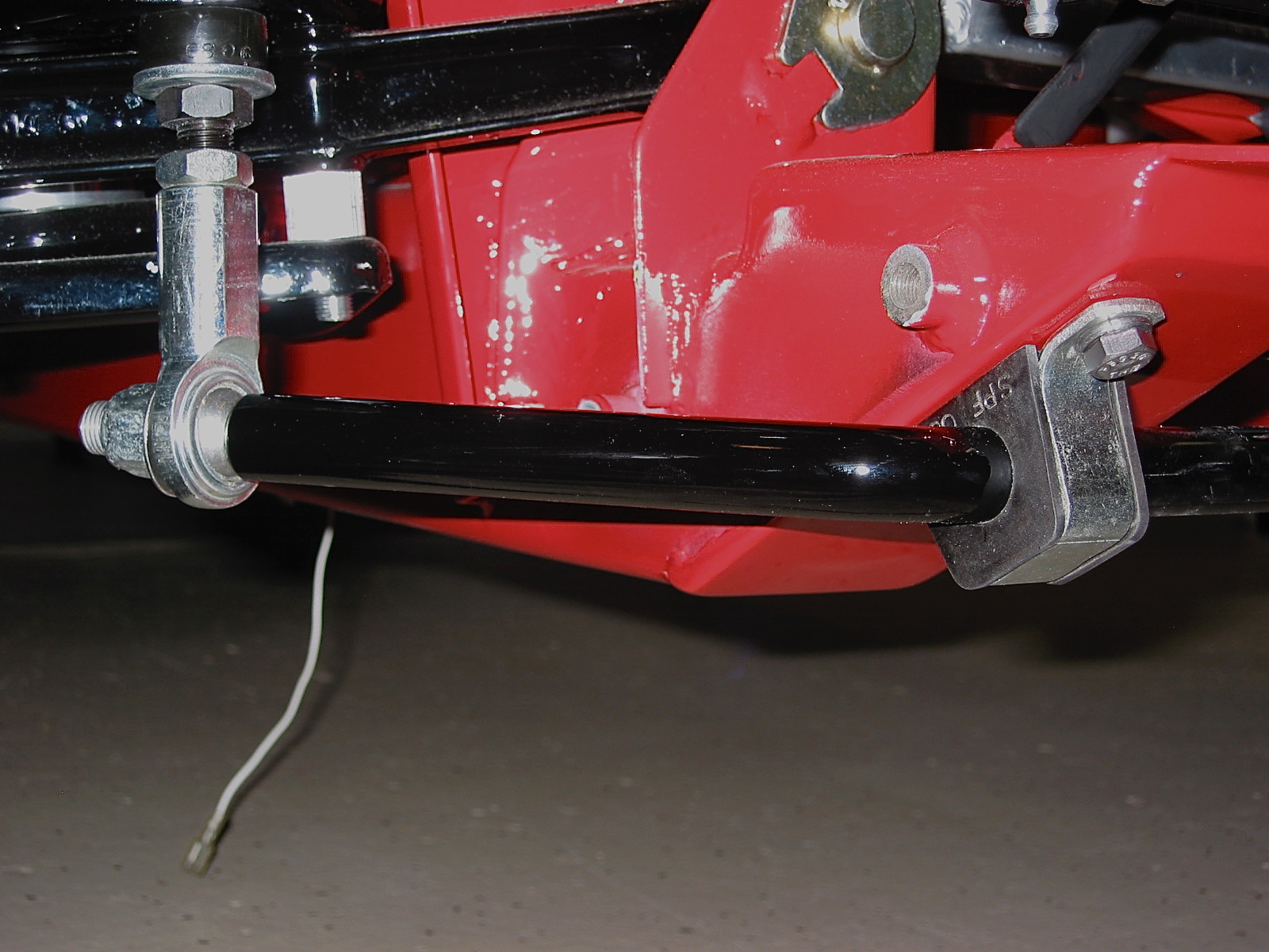
Anti-sway bar mounted 1
I cleaned up the Toyota W57 5 speed gearbox that I will be using with my Smitty conversion kit and painted it. Attaching the Smitty bellhousing makes it easy to stand the gearbox on end to clean and paint.
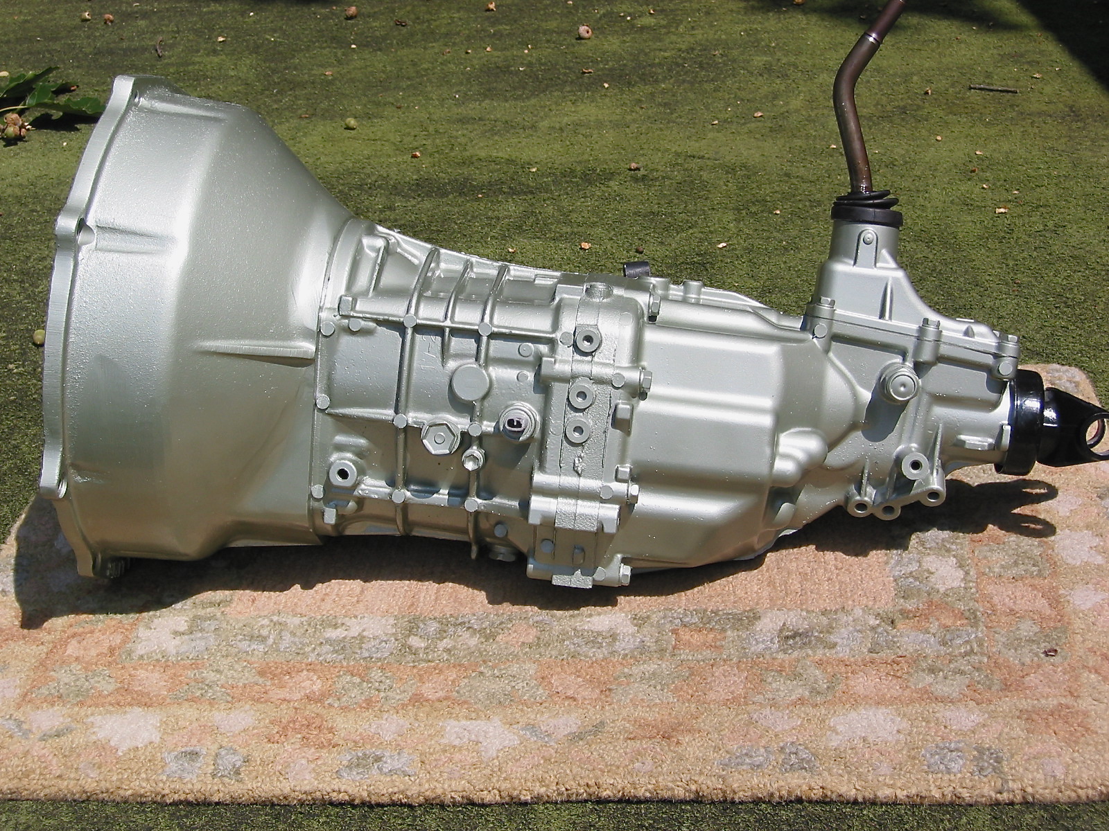
Toyota gearbox 2
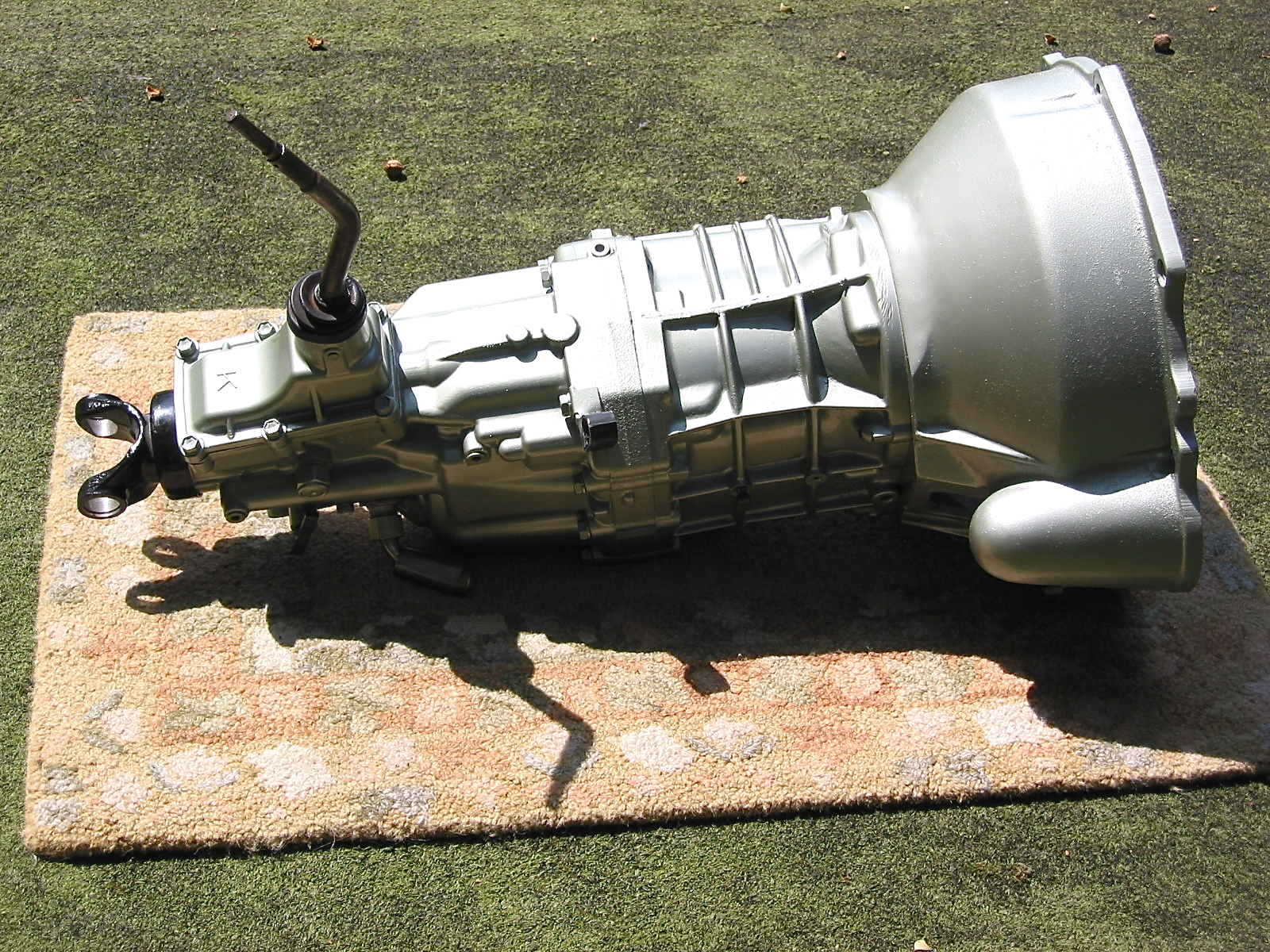
Toyota gearbox 4
I used some 3M black rope caulk to seal the edges of the windscreen frame and then installed the painted windscreen posts to the frame with the 8 chrome #10 screws. The toggle clamp retaining studs were then also attached.
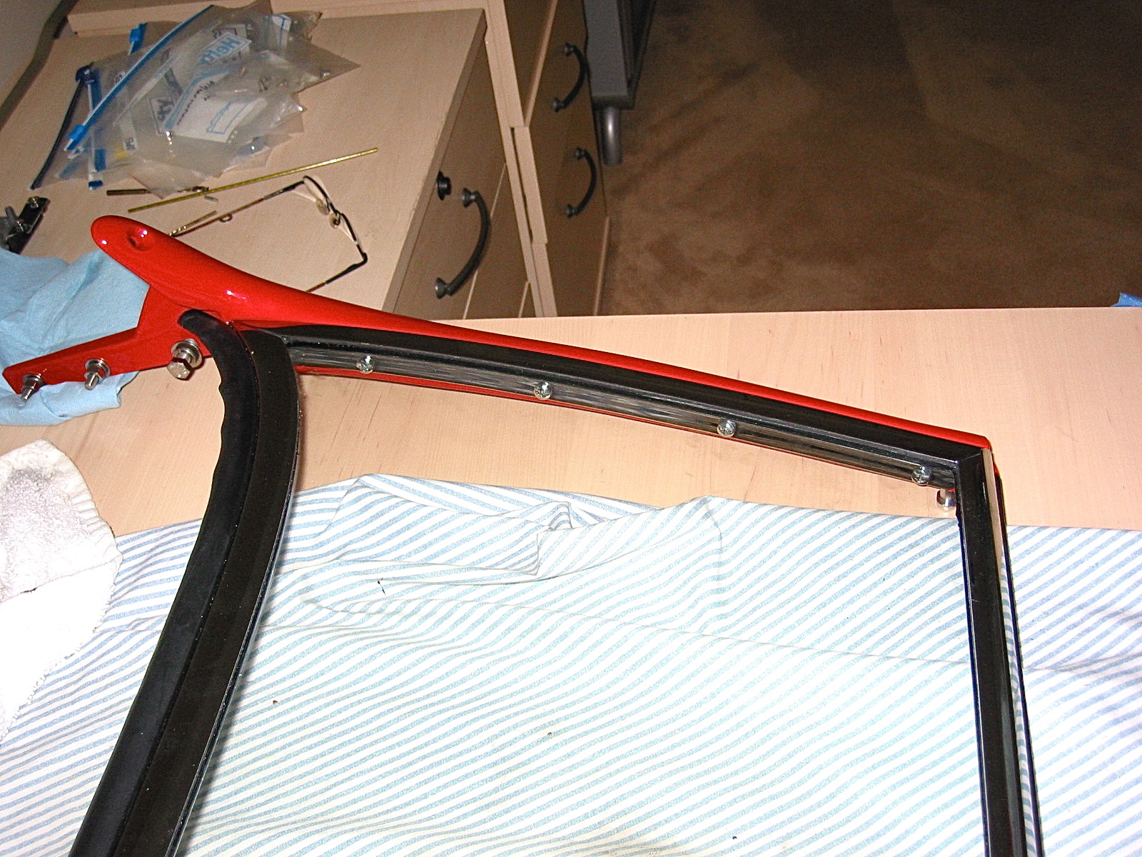
windscreen mounting
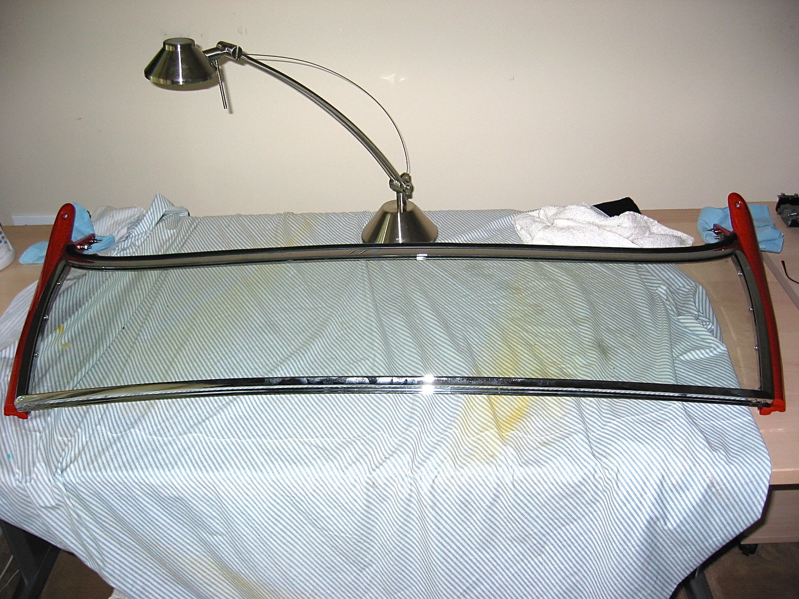
Assembled windscreen
I returned to the boot lid and installed the boot lock with four flat head phillips, 1/4” x 3/4” screws. The lock was adjusted at this point as far down as allowed. Next was the boot rubber seal that is glued to the lid. The seal came from British Car Specialists and seems to be pretty close to original. I glued it with 3m black weatherstripping adhesive. I applied the adhesive to the lid and the gasket in approximately 6-8” sections, waited for it to get tacky, pressed together and then moved to the next section. The seal ends were glued together just below the lock.
Boot Seal
Boot Lock and Seal
There are six #10 flat head machine screws that fasten the rear shroud to the superstructure. I installed the six through the back of the boot opening in the shroud.
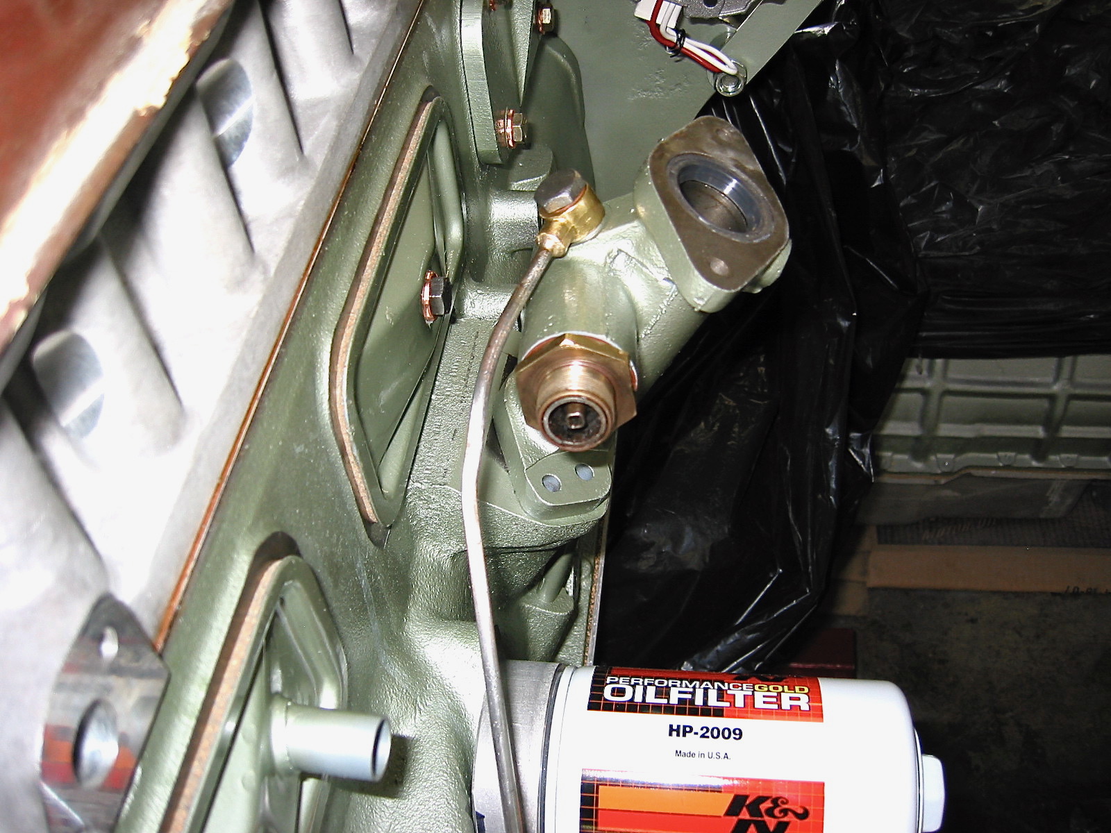
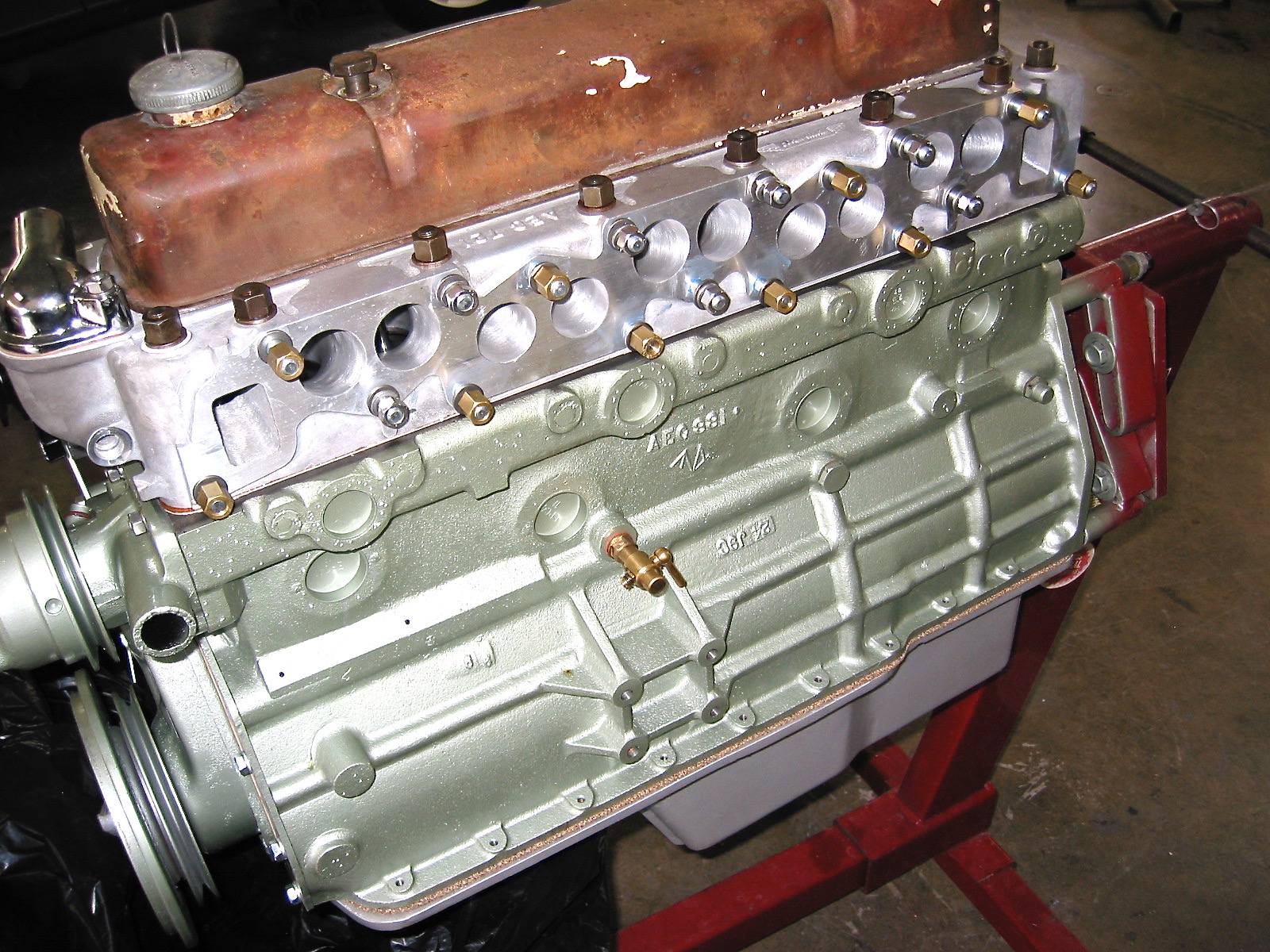
I went out to visit Jack at Coach Works and check on the progress of the motor assembly. I was pleased to find that he had mounted the spin-on oil filter, the alternator with the bracketing kit from Hendrix Wire Wheel (made by Don Lenschow), the rebuilt original water pump and pulley from World Wide Auto, the tach drive, the harmonic balancer and crank pulley, the oil feed line, the drain valve, the head gasket and Denis Welch aluminum head, the chain tensioner and timing chain, the timing chain cover, the tappet covers and the aluminum oil sump from British Parts Northwest. The BPN aluminum oil sump bolted right on with no adjustment required of the oil strainer or drain pipes.

Spin On Oil Filter
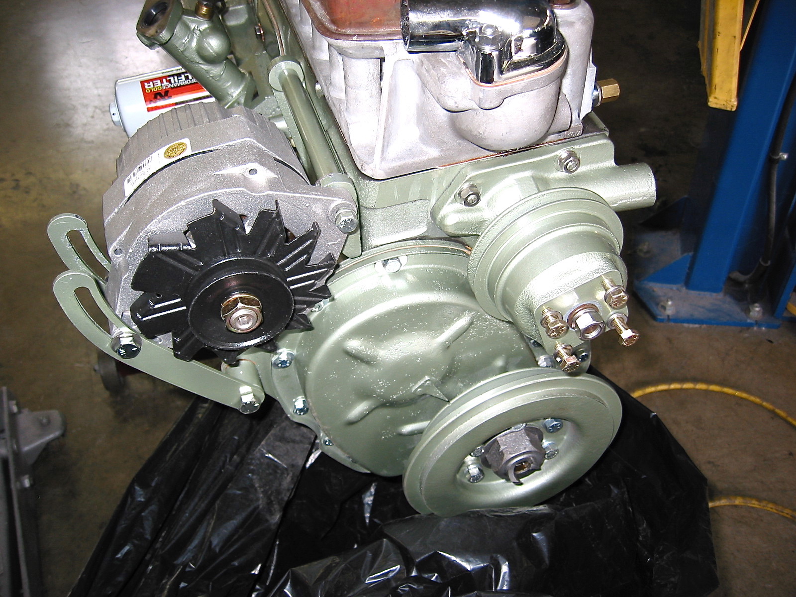
Water Pump and Alternator
Tach Drive
Coolant Drain Valve

Tappet Covers
I failed to mention in earlier posts that I had ordered and received a new aluminum head with valves, springs and etc. from Dennis Welch Motosport. I ordered the “Fast Road” version. Yes, it did make me happy
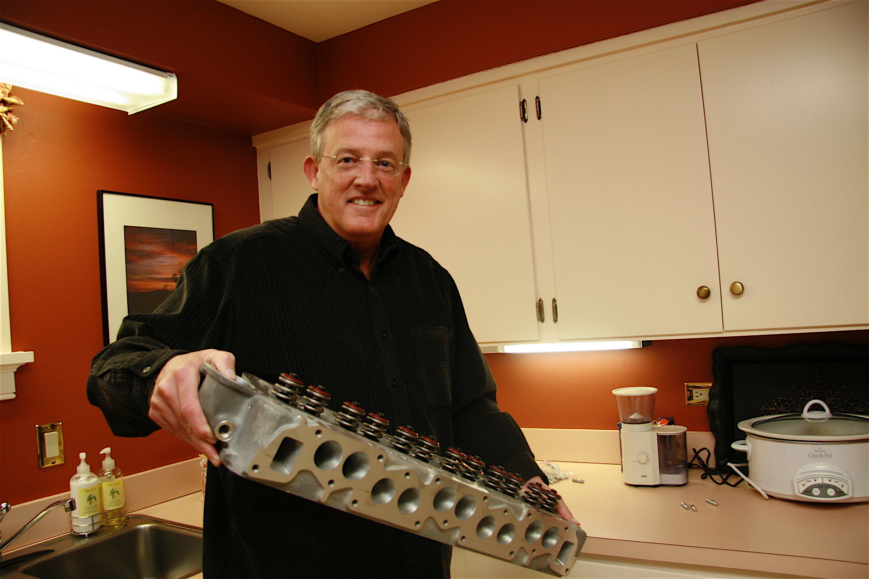
A present for myself!
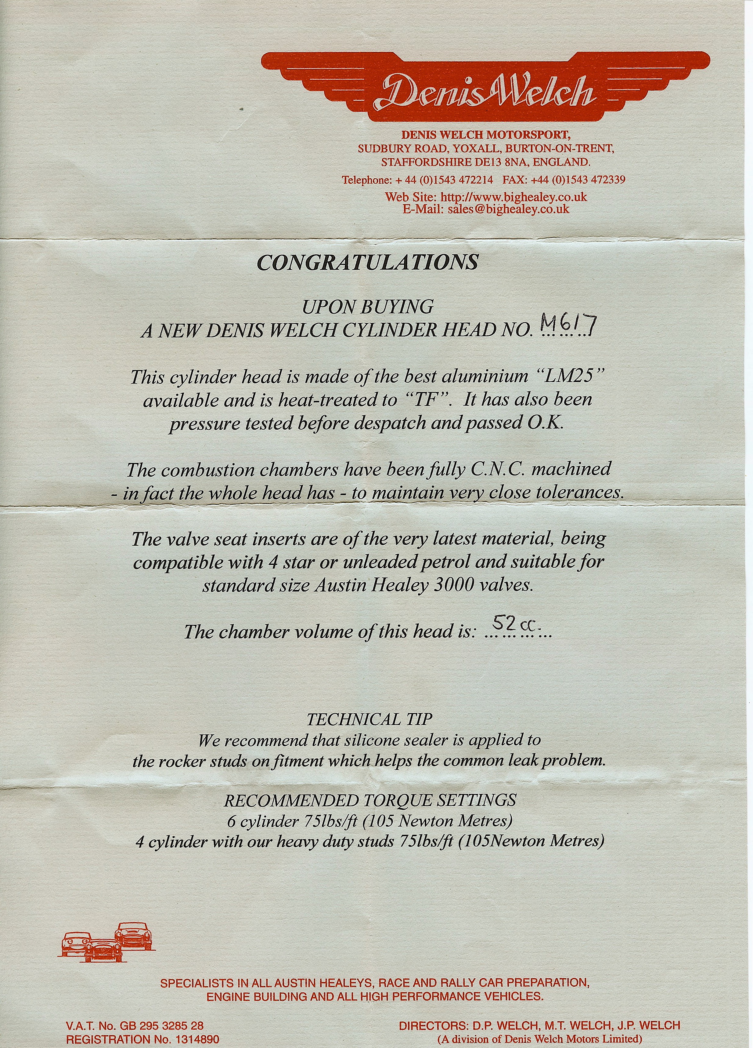
Aluminum Head Tech Sheet
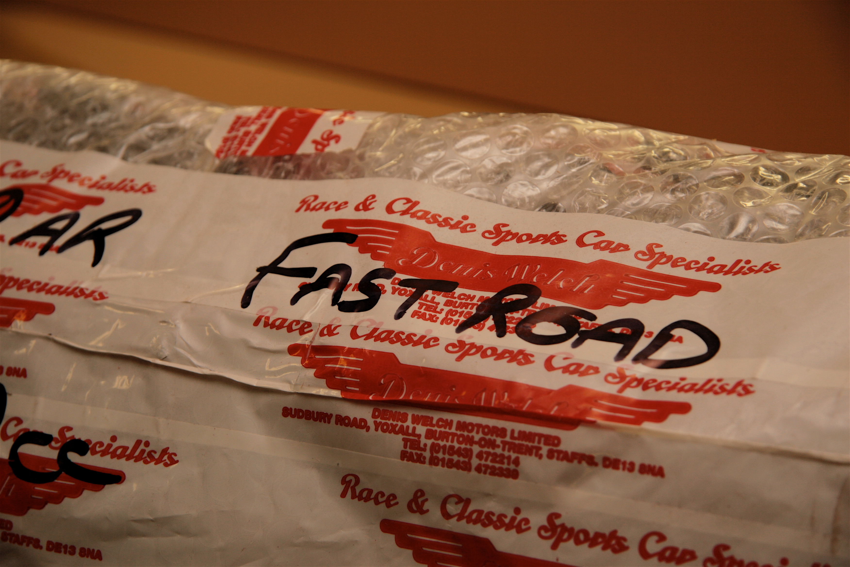
You got it!

New Studs
I got over my fear of touching the rear shroud! I placed it on the superstructure and bolted it on through the two steel threaded mounting plates near the front of the shroud. I then clamped the bottom lip in the rear
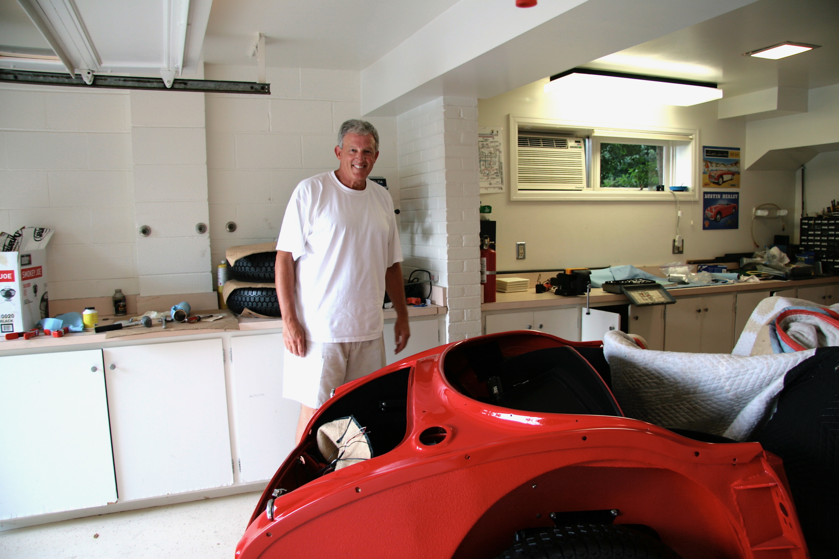
Fitting Rear Shroud
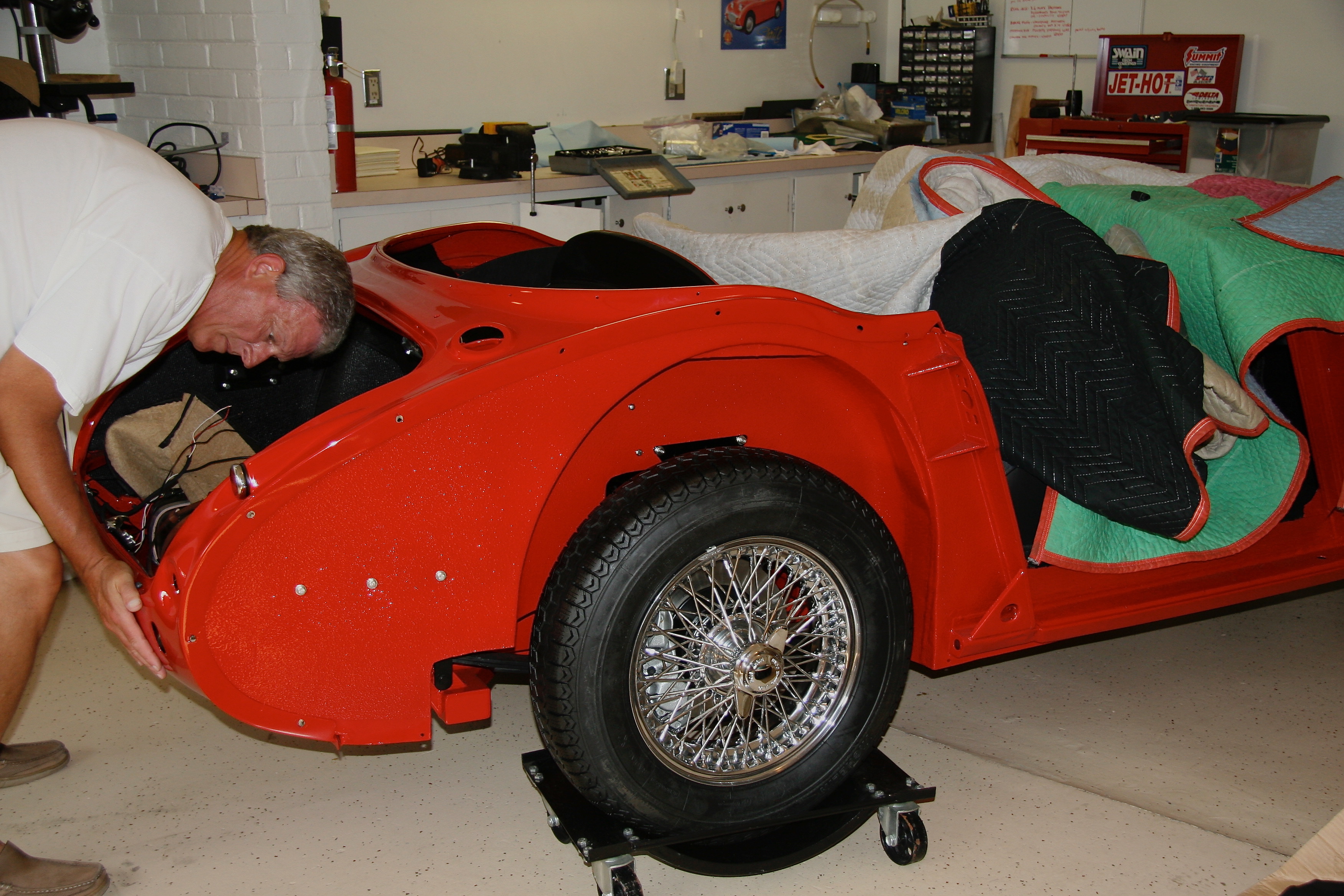
Fitting Rear Shroud 4
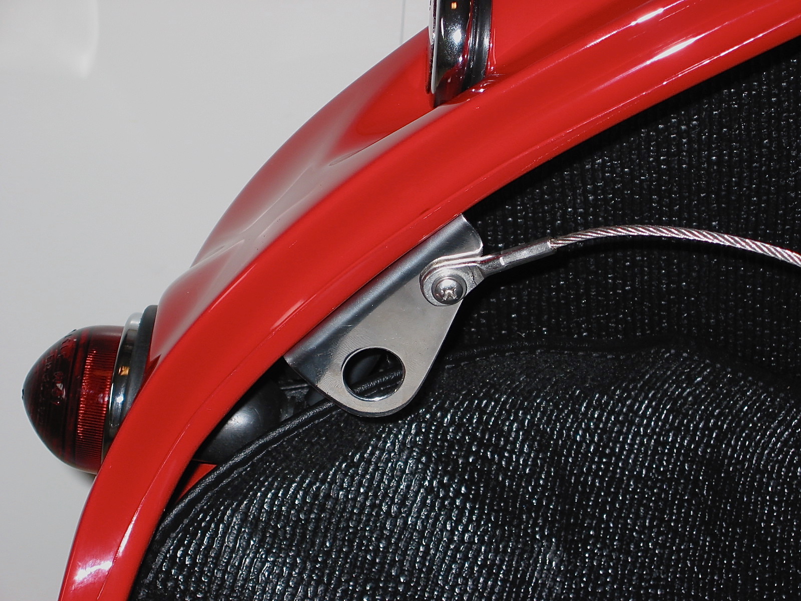
I mounted the rear reflectors that I had converted to lamps A-H Reflector conversion Charlie Baldwin and the rear lights/turn signals.

Rear Lights
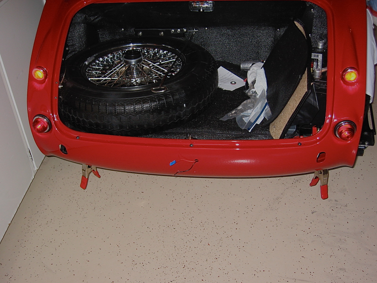
Rear Lights 2
I discovered one reality the hard way. On the left turn signal lamp you have a red wire, a white with purple wire, and a black wire (the right lamp is the same except the white wire has a brown stripe in it rather than purple). These red and white wires must go to their proper terminals or you won’t end up with the turn signals functioning properly. I also learned that those chrome trim rings can be a pain to install in the rubber lamp boots! Patience is required along with tools like a wooden cuticle tool and dental picks. I am sure they had those on the assembly line.
After installing the lights, I put the tenax studs in place for the soft top and tonneau. I used a leather washer against the car paint and then a nylon washer to lift the stud away from the paint slightly.
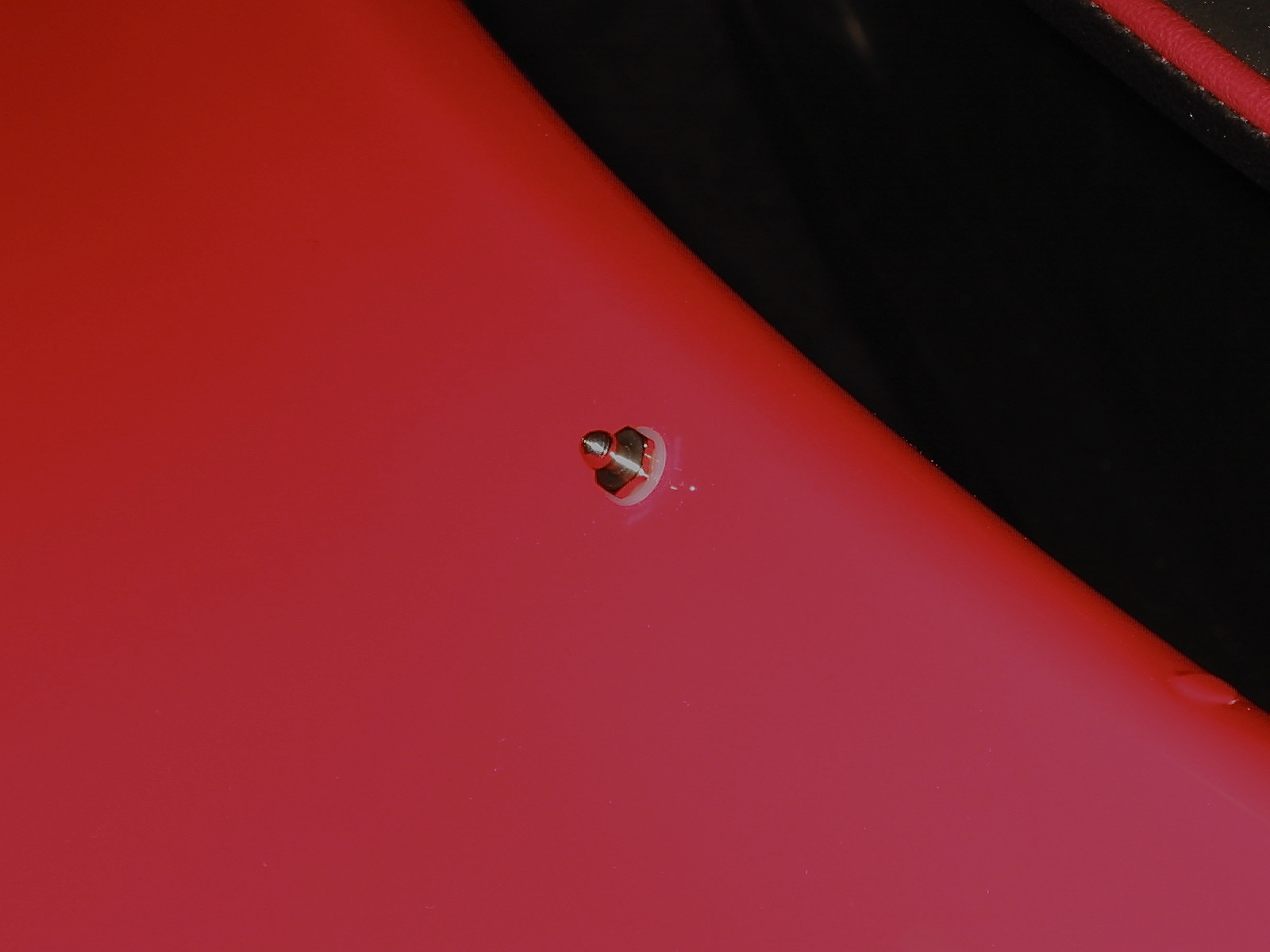
Tenax Stud
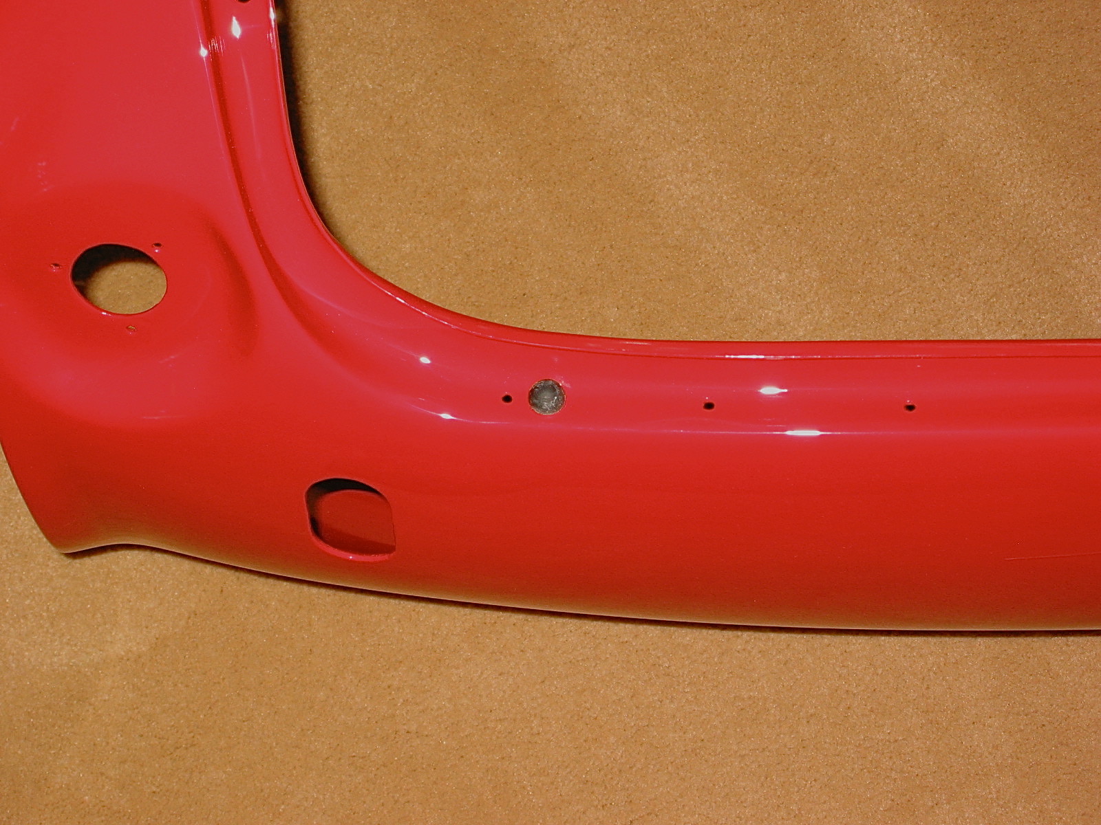
Next, I installed the fuel tank filler pipe and the aluminum Aston flip-top fuel cap. Not original, but I sure think it adds a nice touch!

Fuel Filler Pipe Joint
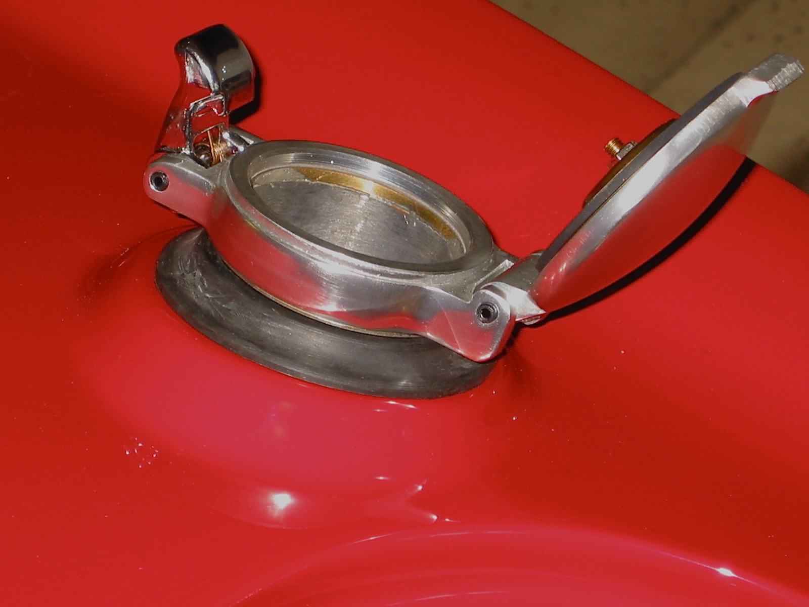
Aston Fuel Filler Cap 3
There are three rubber buffers that are inserted through the rear shroud and the frame hoop to help set the height of the boot lid on the shroud.
Boot Lid Rubber Buffers
I am going to wait another week or two to install the boot lid on the car, but I went ahead and attached the locking boot handle, the “Austin Healey” script badge and the “3000 Flash”. I also attached the prop rod rubber clip and the lock. I purchased stainless prop rods and prop rod stay brackets for the boot lid and bonnet from Wicker’s Paint and Body Shop (Unfortunately, no longer in business).

Boot Lid Hardware
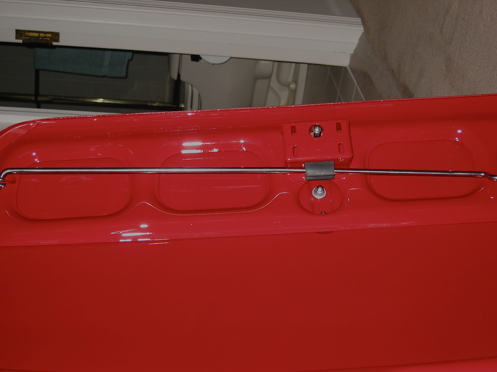
Stainless Prop Rod
Prop Rod catch
Prop rod stay bracket 2
Rear shroud and boot lid.
Jeremy returned from vacation and painted the rear shroud and boot lid. I picked them up and they do look beautiful. I am reminded of that feeling I had when he unloaded the frame and superstructure from his trailer at the house. I am afraid to touch anything for fear of damaging the paint. As before, I suppose with time I will get over it.
Still waiting!
Jack Harper’s Work on the engine rebuild continues and I wait.
Jack Harper has gotten to work on the engine. The crank is in and the Denis Welch rear oil seal kit has been installed. The block, timing gear cover and other assorted parts have been painted the metallic green standard for all later Healeys. Jack is installing new Hepolite pistons, 40 thousands over. All new core plugs installed as well. I assembled the carb heat shield insulation panel to the heat shield with the proper copper split rivets and washers. The motor mounts were also sprayed the metallic green.
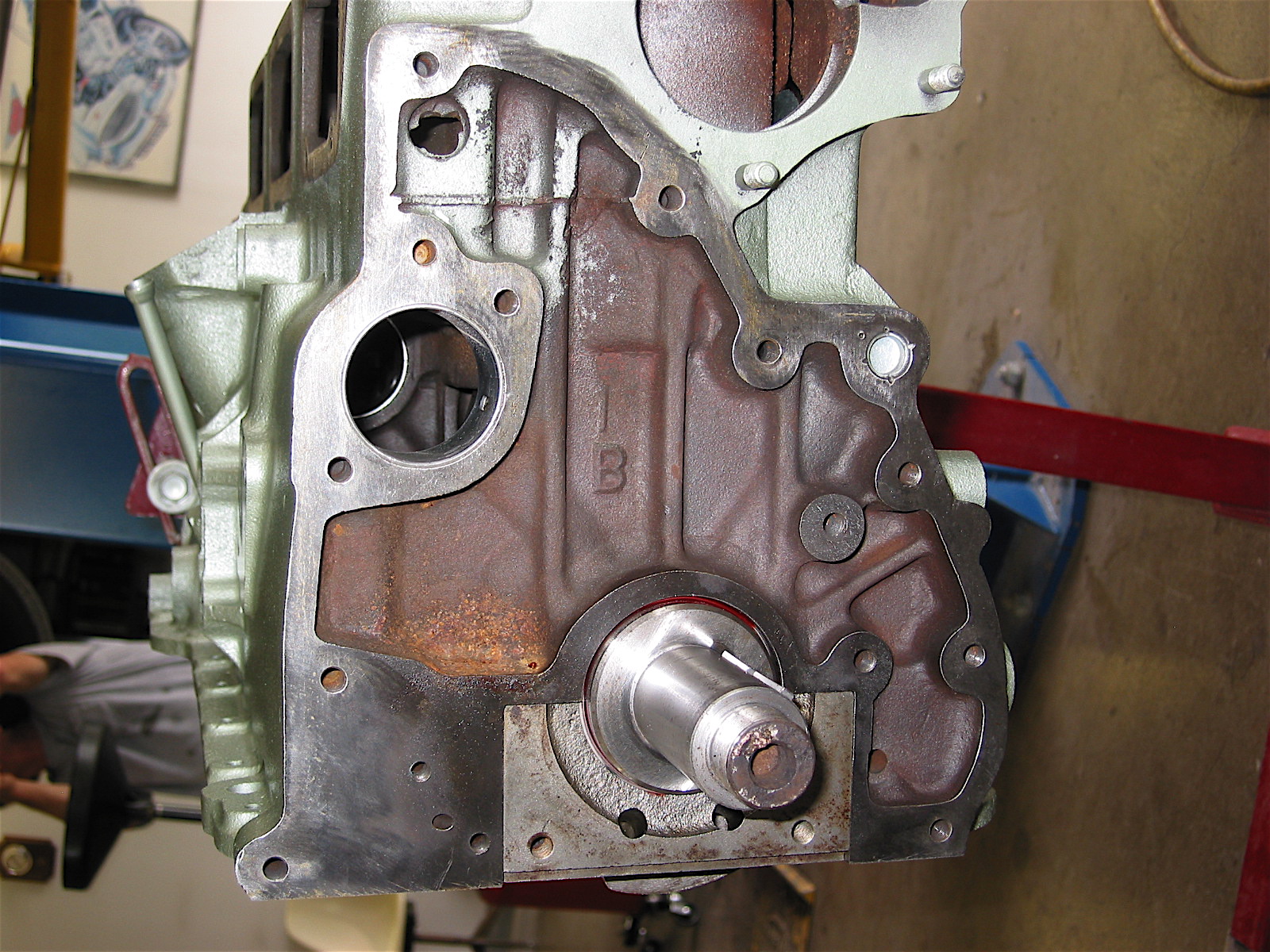
Block Front
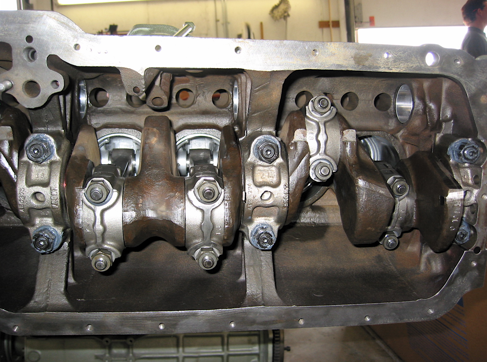
Crank View 1
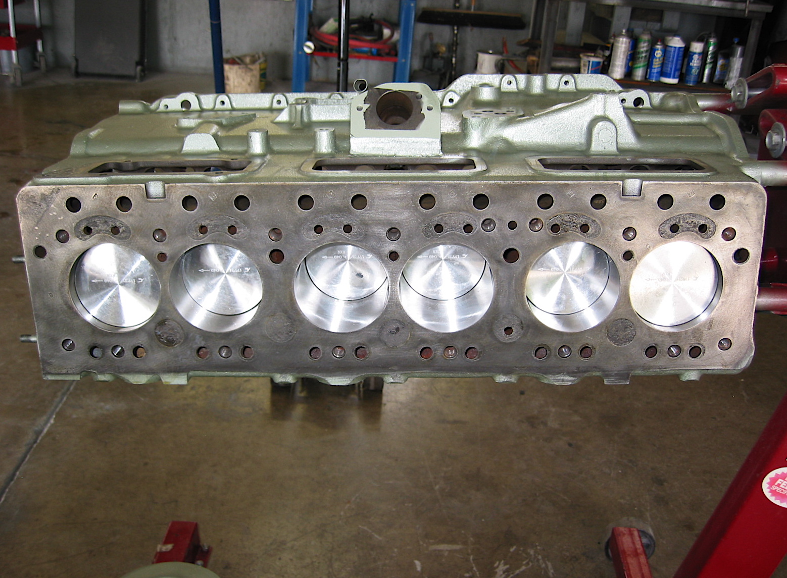
New Pistons
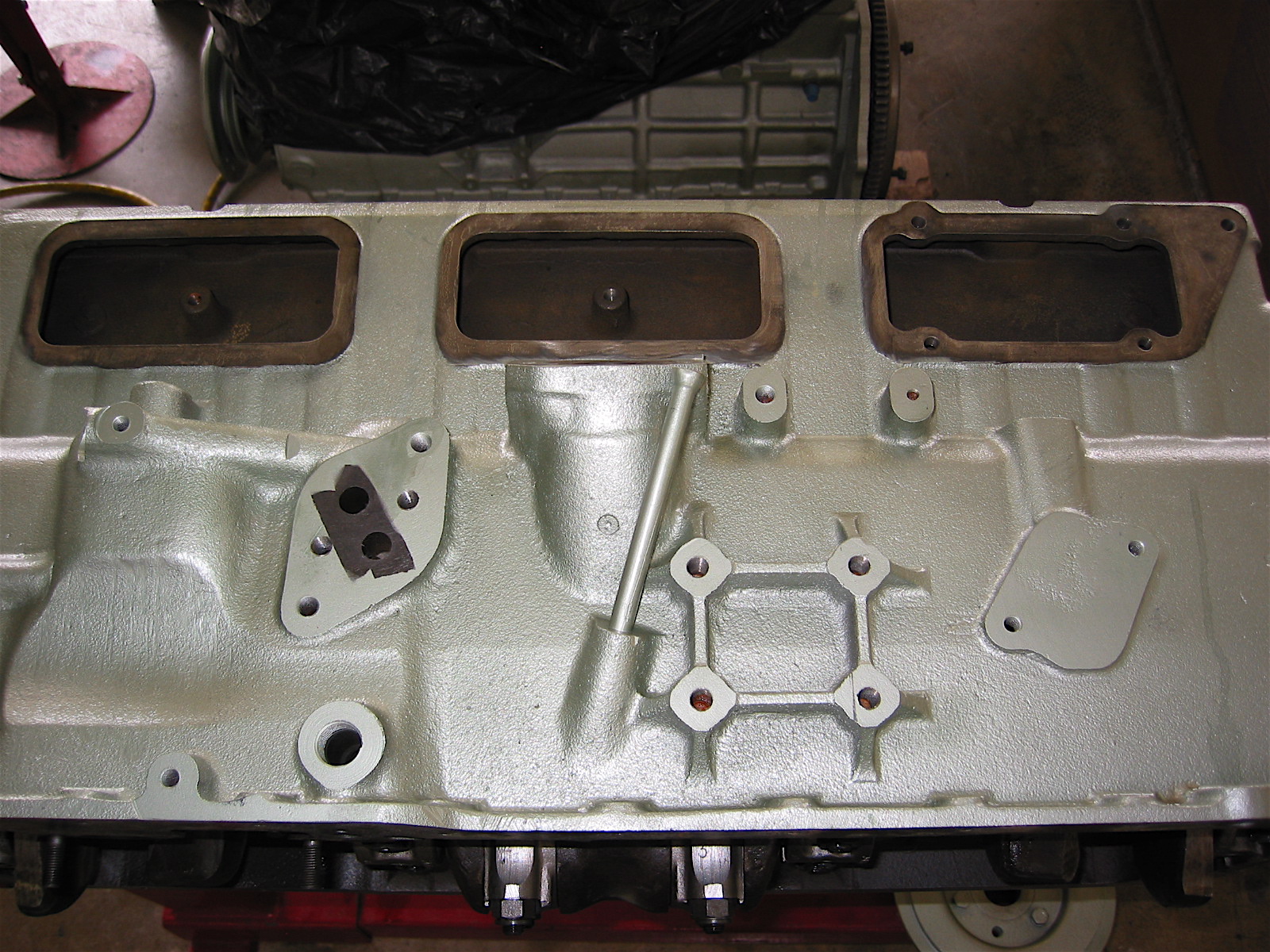
Block right side
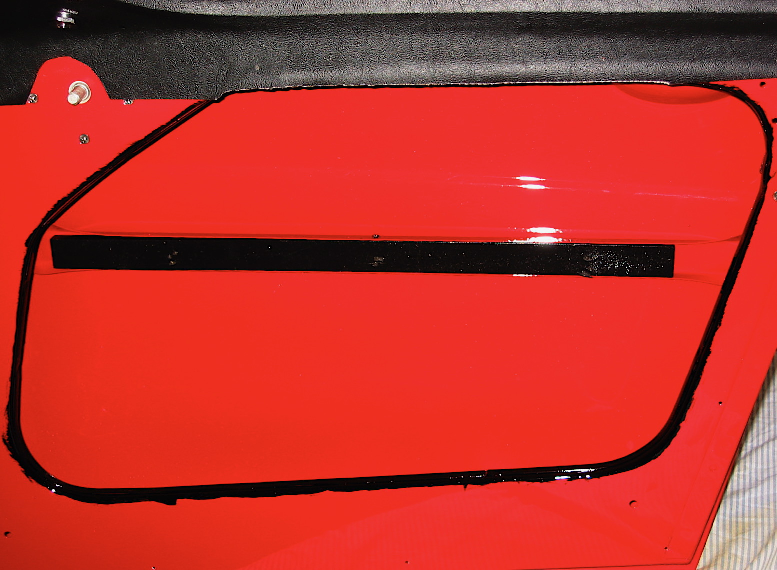
Jeremy Turner finished the painting of the doors so I picked them up and installed the various door components including the Heritage upholstery panels. As has so often been the case, Rich Chrysler provided a narrative description of the Installing Door Panels.pdf that proved to be very useful.
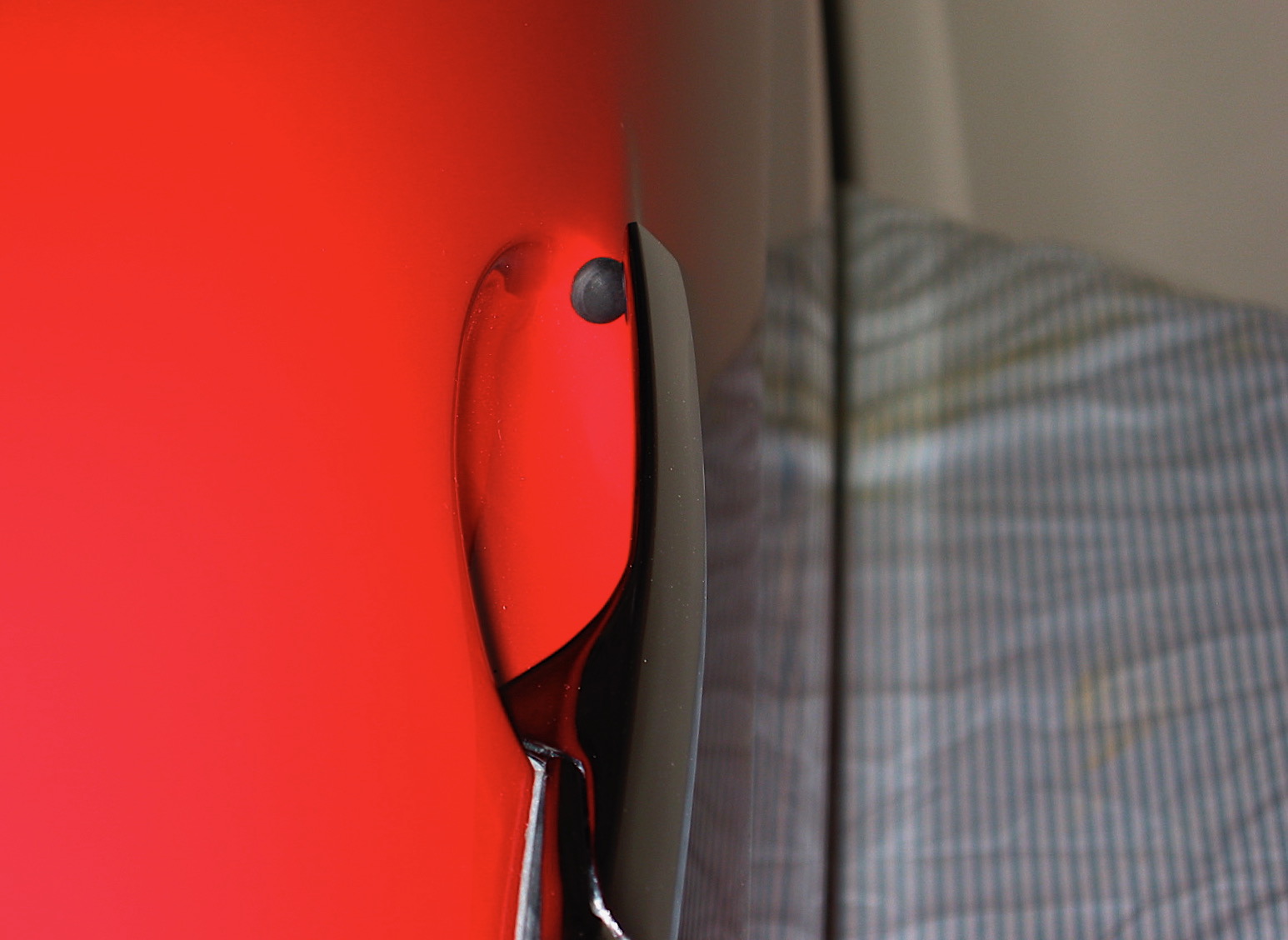
I began by gluing a strip of vinyl across the top of the interior of the door. This vinyl fills the gap between the aluminum door trim and the upholstered panel. I then installed the chrome exterior door handle including the little rubber bufferthat protects the paint from handle contact. The handle is held in place by two #10 screws, the rear is a press fit stud into the handle and the front a phillips head screw inserted through the handle and the door. The handle was followed by the opening and closing hardware that had been cleaned, painted and lubricated.
Door handle exterior
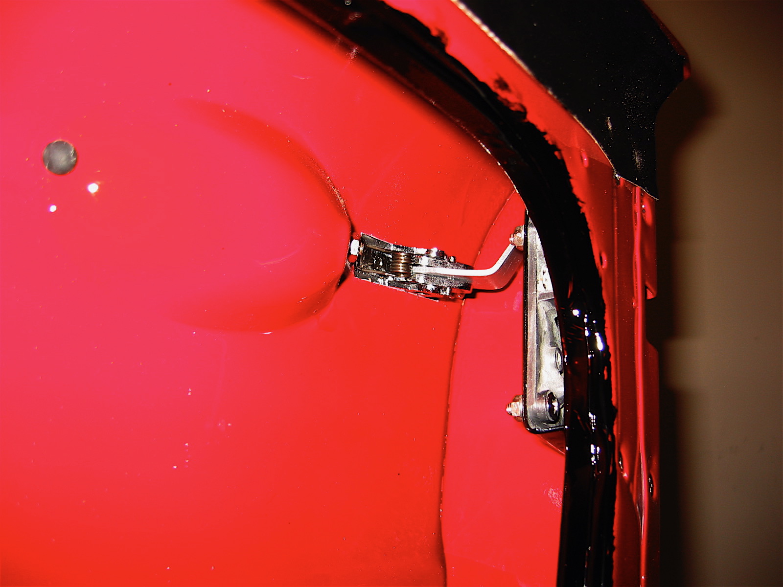
Door handle Inside 1
While it pained me to do so, Rich indicated that at the factory they brush painted, by hand, the ring around the door panel opening with paint the color of the interior vinyl, so I followed his direction. I then installed the wooden tack strip in the center of the door that is used to secure the interior door panels. The image below shows the vinyl at the top of the door, the hand painted black surround and the wood strip.
Trimming Door Interior
Continuing to follow Rich’s guide, I then fit the lower vertical upholstered panel into the door. There is a vinyl flap that must be pulled up as the panel is put into place. Then I fit the upper vertical upholstered panel and carefully drilled three holes through the panels into the wood strip and fastened it all together with three #8 x 5/8” stainless polished (rather than the original chromium). Finally, the flat vinyl covered floor piece was installed into the bottom of the door.
I wanted to use the original screw holes already in the doors for the flat upholstered door panels, so I made a template with butcher paper to mark the holes and then transfered the holes markings to the door panel. I held my breath as I drilled holes in the panel, but as it turned out everything fit nicely the first time!
The BT7 cars did not have interior door pulls, but I decided to install them to help prevent pulling the edge of the upholstered panel to close the door. They were available from Moss Motors and they do look original as their design matches the door handles.
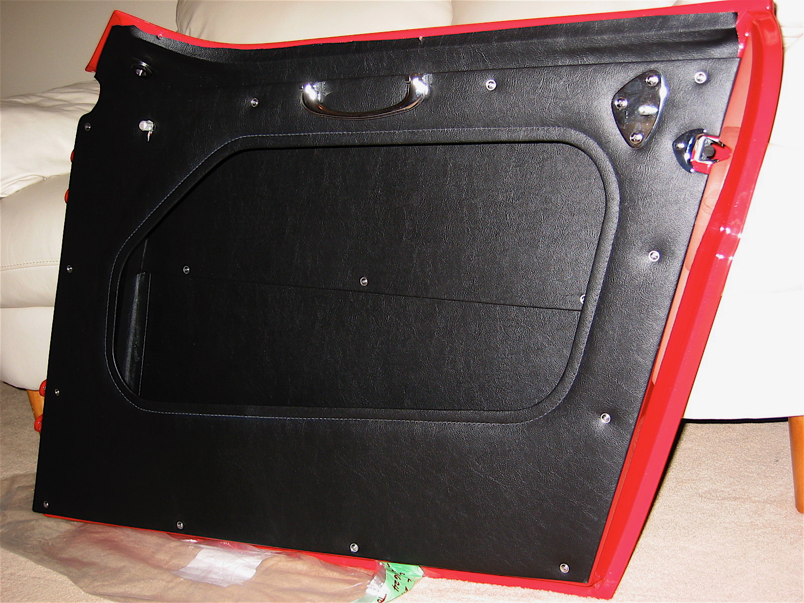
Door Upholstery
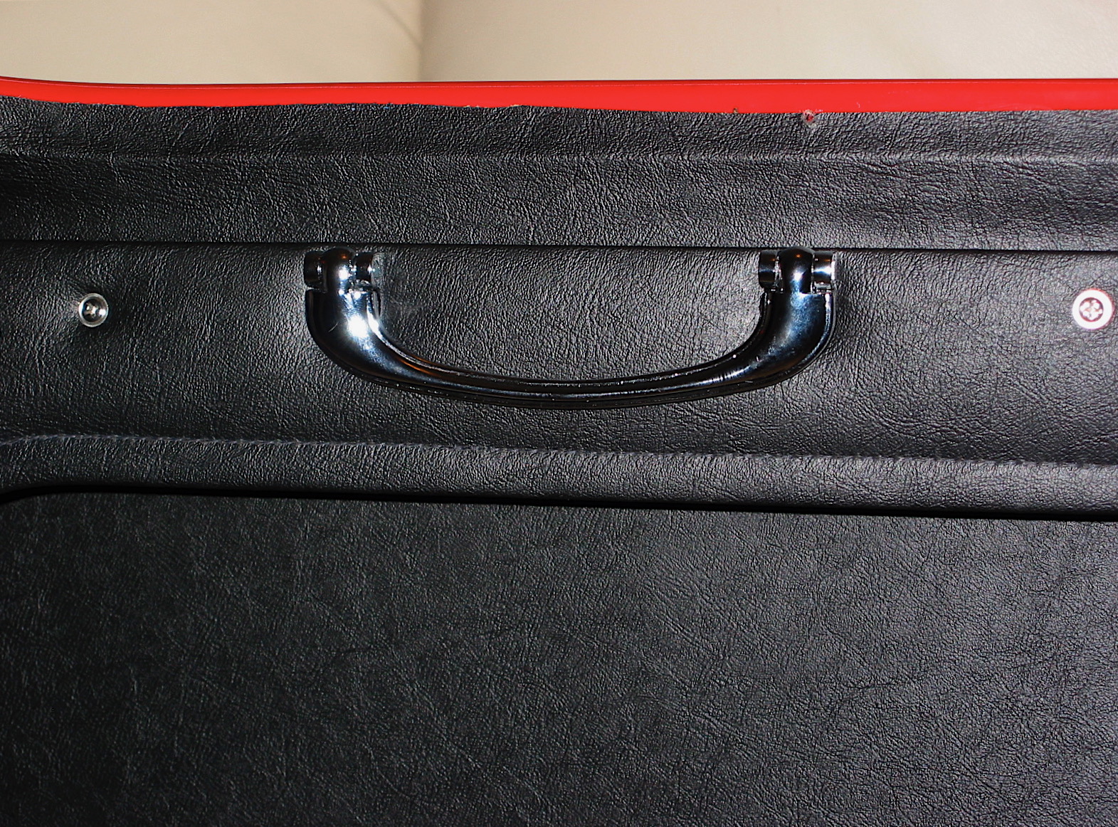
Interior Door Pull

Side Curtain Mount
The interior door handle installation is little challenging in that one must insert a small (approximately 3/4” pin) through the handle and the operating mechanism shaft. I found it easier to use a heavy duty coat hanger. I cut half way through an 8” rod of the hanger at the 3/4” mark, inserted the rod and then bent it to break it off in place. Much easier than trying to get that little pin to slide in! Next I installed the side curtain mounting plate and the door latch trim to finish up the first door. The second door was a repeat procedure of the first.
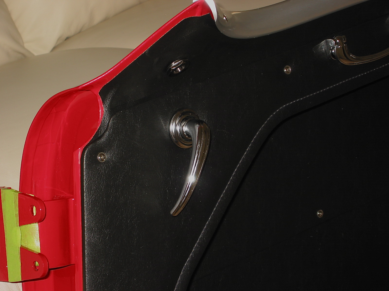
Interior Door Handle RH