There are a number of wonderful resource books about Big Healeys. Two that I found to be very useful were the Anderson-Moment Restoration Guide and the Original Austin-Healey by Anders Clausager. Of course, in the actual assembly the Service Parts List and the Workshop Manual are invaluable.
While certainly not a complete library, the following references were used in preparation for the restoration of my 1960 3000 BT7.
Austin-Healey 100/100-6/3000 Restoration Guide by Gary Anderson and Roger Moment, MBI Publishing, 2000.
Original Austin-Healey, the Restorer’s Guide to 100, 100-Six, and 3000 by Anders Ditlev Clausager, Bay View Books, Ltd., 1990.
The Healey Book, A Complete History of the Healey Marque by Bill Emerson, Coterie Press Ltd., June, 2002.
Austin-Healey, A Celebration of the Fabulous ‘Big’ Healey by Bill Piggott, Haynes Publishing, 2002.
The Big Healeys, A Collector’s Guide by Graham Robson, Motor Racing Publications, Ltd., 1981.
My World of Cars, Donald Healey with Peter Garnier and Brian Healey, Patrick Stevens Ltd., 1989.
Austin-Healey 100 & 3000 by John Heilig, Motorbooks International, 1995.
Essential Austin-Healey 100 & 3000, The Cars and Their Story, 1953-67, by Mike Lawrence, Bay View Books, 1994.
Austin-Healey 100 & 3000 Series, by Graham Robson, The Crowood Press Ltd., 1994.
Austin Healey, The Story of the Big Healeys, by Geoffrey Healey, Dodd, Mead & Company, 1978.
Austin-Healey 100 & 3000, 1952-1968, by David McLavin & Andrew Tipping, Osprey Publishing, 1992.
The Healey Story, by Geoffrey Healey, M.C.K. Healey Partnership, 1996.
Austin-Healey 100-6 and 3000 Workshop Manual, and the Service Parts List, British Motor Corporation Ltd., 1968.
Rich Chrysler’s pamphlet Austin-Healey Restoration is a short document that helps the restorer organize his/her approach to the job and offers helpful suggestion on how to proceed.
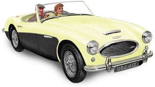
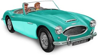
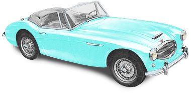
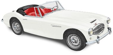
The following observations about key features of the Healey have been gleaned (and edited) from the Anderson/Moment and Clausager reference books for my use in restoration only. The images represent the paint colors and combinations available from the factory for the 3000. They are available at Roger Los’s http://austinhealey.com/ web site.
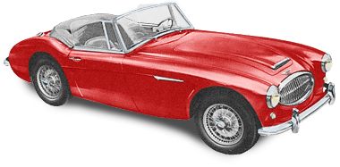
Colorado Red
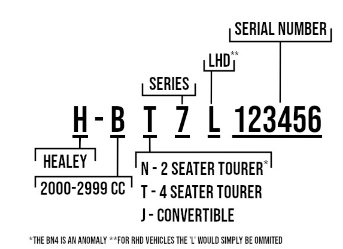
Serial numbers
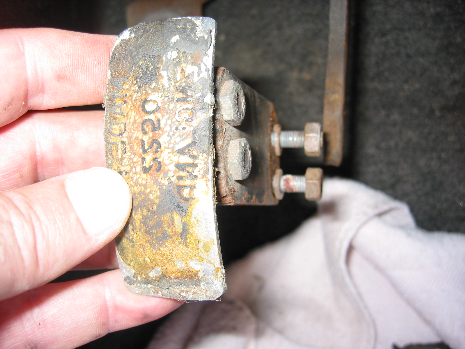
Hardtop serial number above door opening on passenger side, prefix begins with a 4 for BT7s. Car number and body number are found on a firewall plate. The body number is also found on the splash panel, the hood latch bracket, the hood hinge bracket, and the trunk lid prop bracket. Engine number is on a plate on the block.
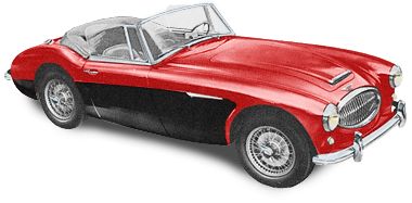
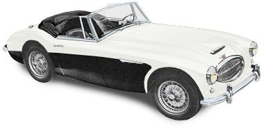
Colorado Red Over Black
Body Panels and Paint
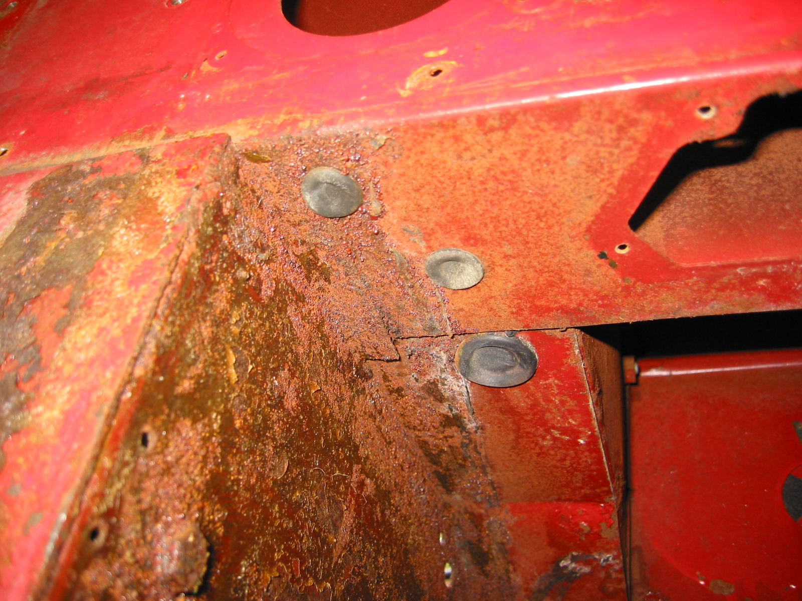
All Healeys were painted with the body panels on the frame. Color combinations can be found on page 89 of the Anderson/Moment book. Dark Brown metal primer was used. The rear shroud is often referred to as the tonneau assembly. The shroud was attached to the body along the back below the trunk with closed head aluminum rivets (not pop rivets). The rivets were solid, visible and painted over. Three pop rivets were used on the top rear portion of the chassis structure on each side. 3 round head rubber buffers were pressed into holes at the center and right and left sides of the boot opening next to the rivets on the boot opening. The lower lip of the rear shroud was brush painted satin black over the body color. The nuts, bolts, screws, washers and tapped plates used to fasten fenders to the chassis were of a variety of types and sizes – shown in detail in the BN7-BT7 parts list. All fender fasteners were painted body color with the body after assembly. The front metal apron had a gap between it and the shroud of 3/4” to 1”. Adjustments could be made by moving the bumper mounting brackets.
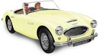
Primrose Yellow
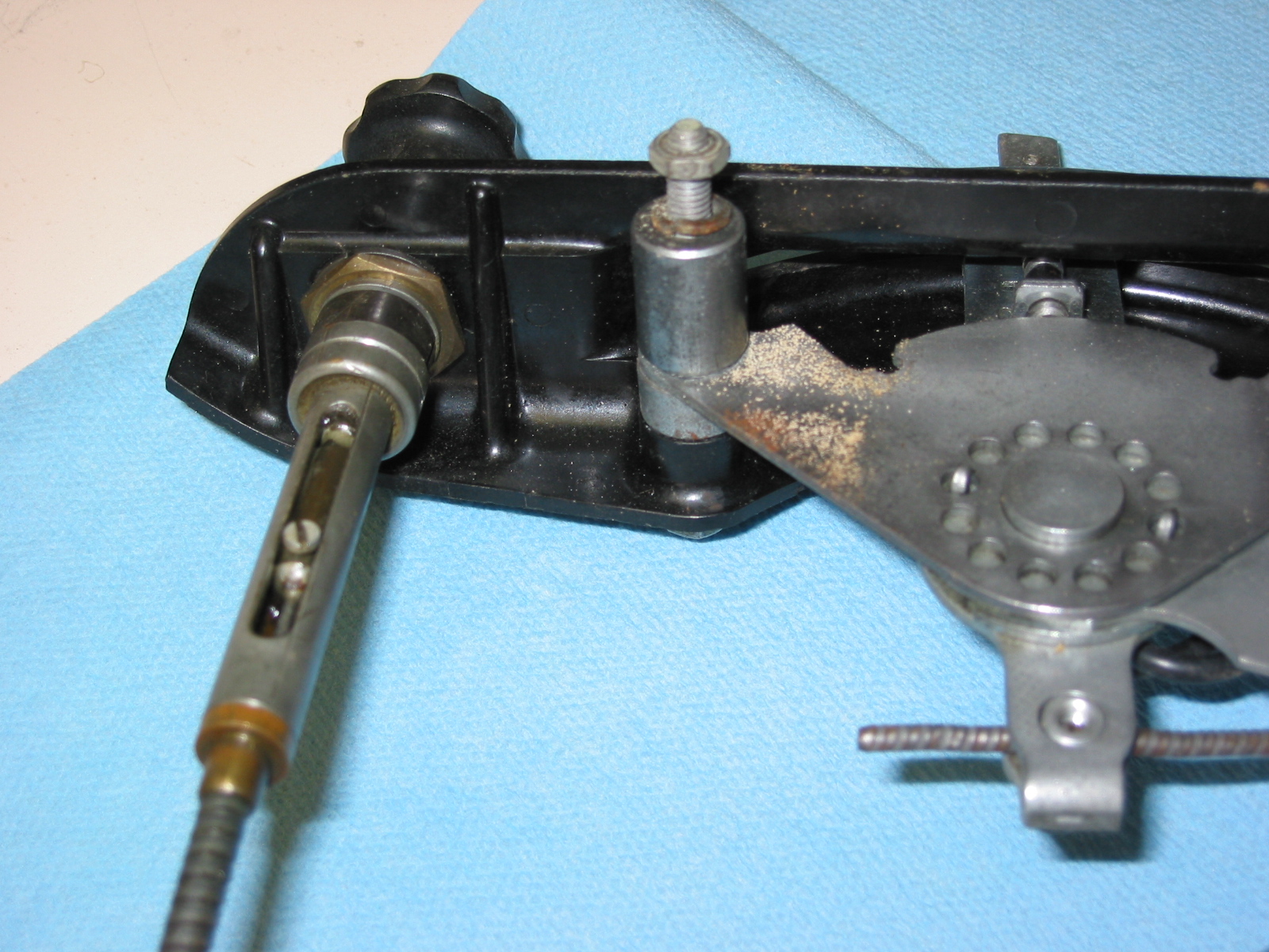
Doors and Door Latches
Door panels on the 6 cylinder cars were two inches longer than those on the 4 cylinder cars. The hinges and mounting screws were painted the body color along with the doors. A door check mechanism was fastened to the door after painting. The pieces of the stay were zinc plated, except for the spring washer, which was finished in black phosphate. Grained vinyl piping was fitted between the trim plate and the rear fender. On all 6 cylinder cars the piping was black and extended up and over the top of the shut face panel. A rubber bumper was pressed into a hole under the end of each external door latch handle to minimize rattling.
Primrose Yellow Over Black
Chrome, Lights and Glass
The upper “eyebrow” on the grill was polished stainless steel. The “eyebrow” was screwed to the sides of the opening with Phillips 10/32 pan-head machine screws. The bumpers and overiders remained unchanged for all of the 6 cylinder cars. The inside cavities were painted dull silver. The front and rear bumpers had different inside mounting arrangements for the bumper brackets. The bolts fastening the bumper brackets to the frame were unpainted.

Pacific Green
The trim moldings around the cockpit were polished aluminum and then clear anodized to have a soft, non-reflective finish. The moldings were attached to the body with chrome plated oval headed Phillips screws and to the doors with sheet metal screws. The rear moldings were secured with machine screws that thread into L-shape steel pieces under the cockpits edge.
Pacific Green over Florida Green
On all 6 cylinder Healeys, two small pieces of silver vinyl plastic with a 1/8” round bead filled the gaps between the headlight and the side lamp, and between the side lamp and the bottom edge of the front fender.
Headlights were mounted in black bowls fastened to the body with Phillips oval-head 10/32 machine screws. They were secured on the inside of the wheel well by spring washers and special unpainted 1/2” deep brass cap nuts. The headlight rim was chrome with a visible nickel-plated brass rivet on the top. The combination parking/signal lamps were Lucas type 594 with clear glass. Number plate lamp was type 467/2 originally one bulb later 2.
The windshield was made of clear (untinted) “TripleX” laminated safety glass. Two trico windshield wipers with “Rainbow” brand polished stainless wiper blades.
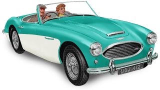
Pacific Green over Ivory White
Interior, Soft Trim and Top
The padded top of the dashboard was called the “scuttle top liner.” The cushion was covered with vinyl with trim piping on the ends. The demister grilles were painted the same color as the interior trim.
The lower edge of the dashboard was covered with two furflex strips matching the interior color.
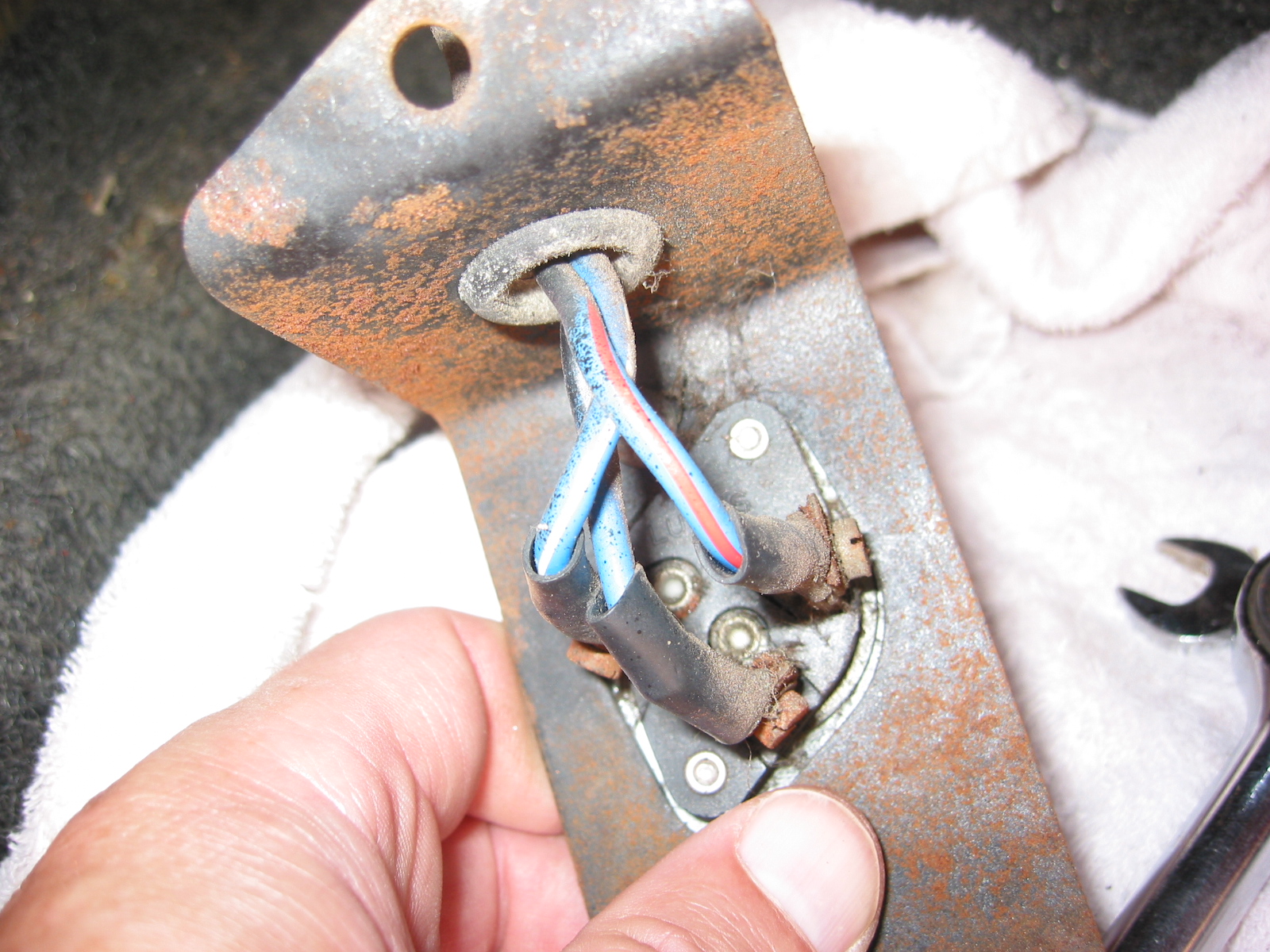
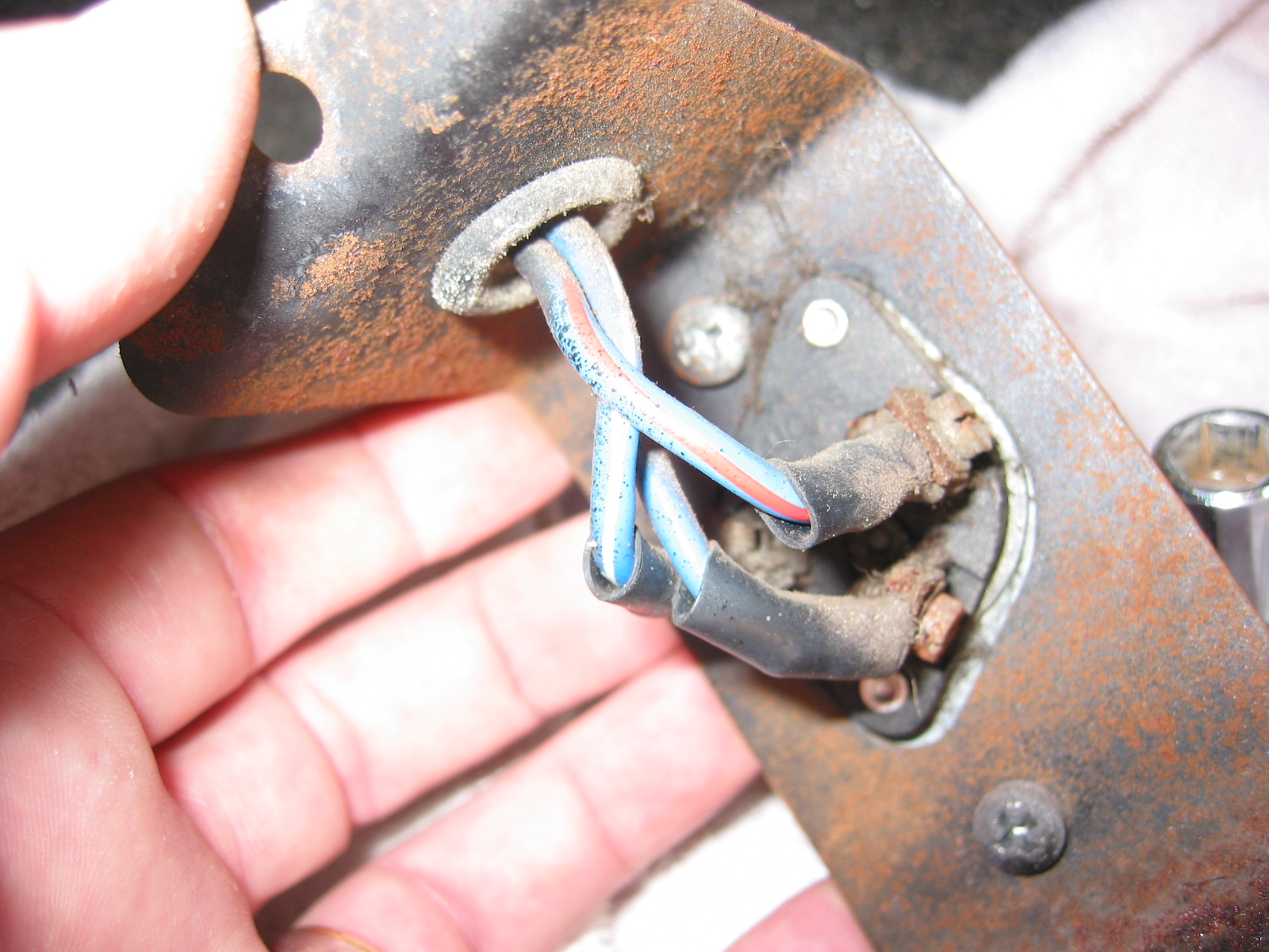
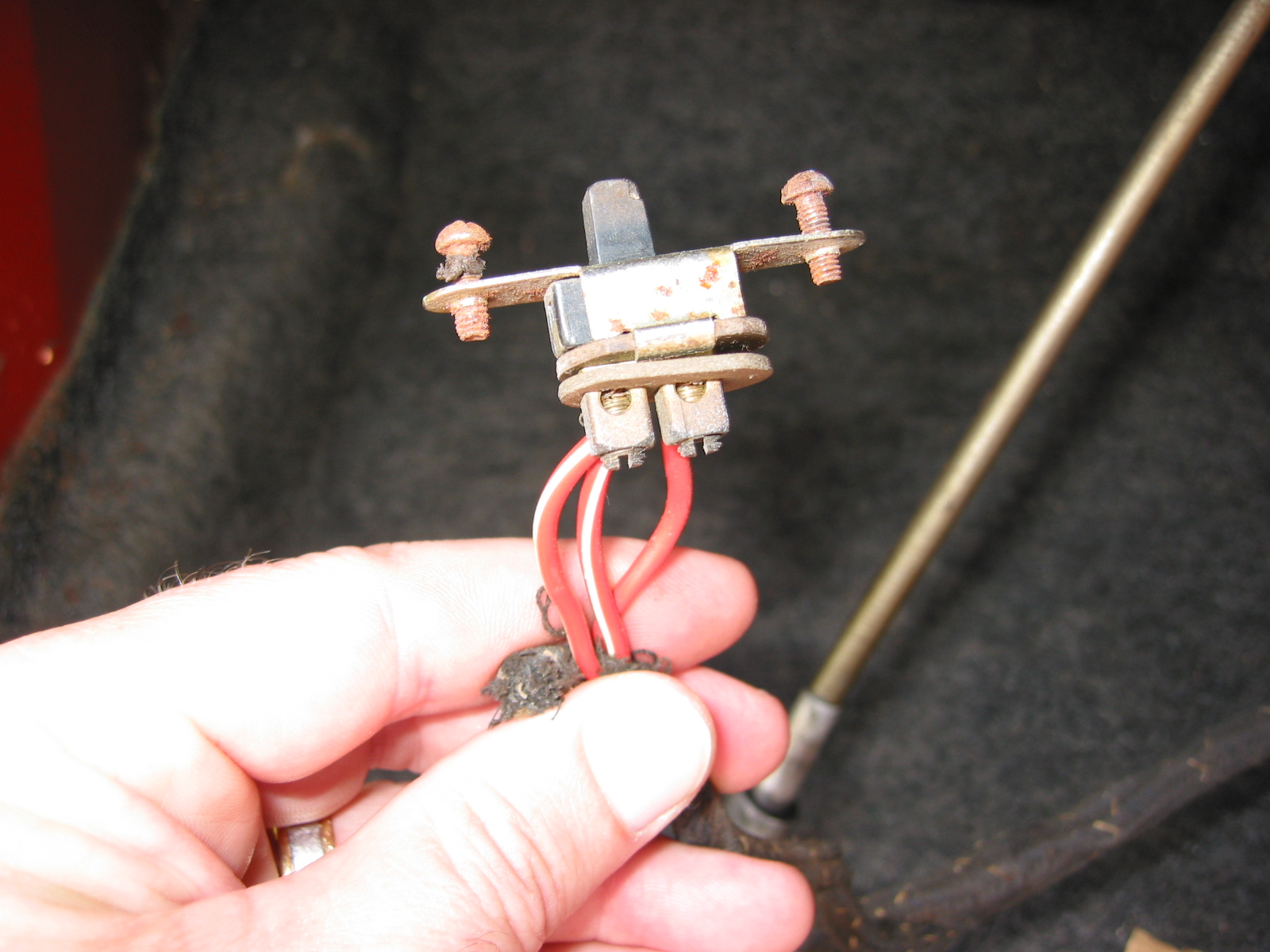
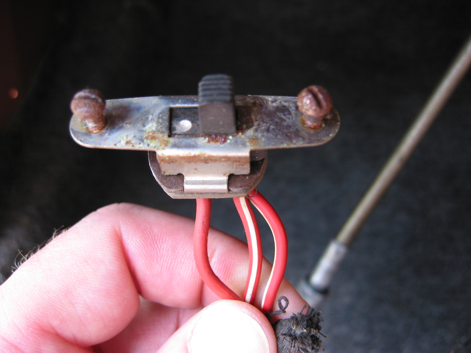
The dimmer switch was an unpainted metal push switch in a black painted u-shaped bracket screwed in through the carpet with two 10/32” Phillips head screws. The wiring harness was exposed to the switch. Blue for power source, blue/red for low beam, and blue white for high beam.
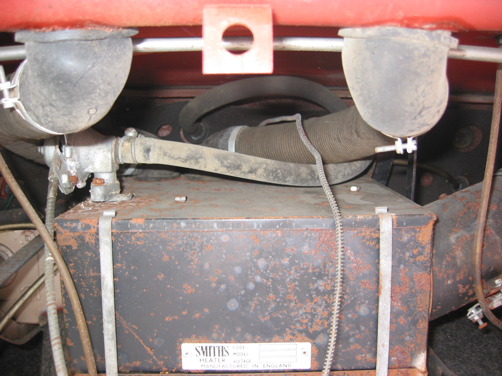
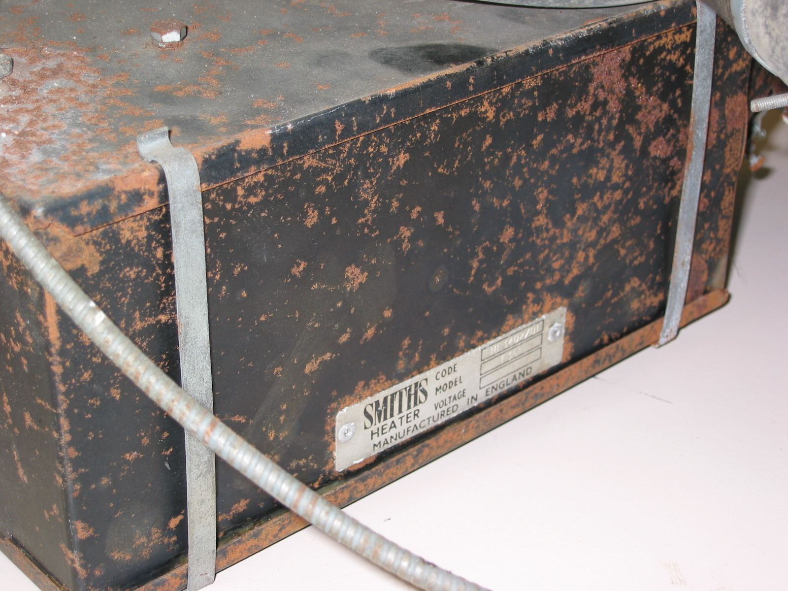
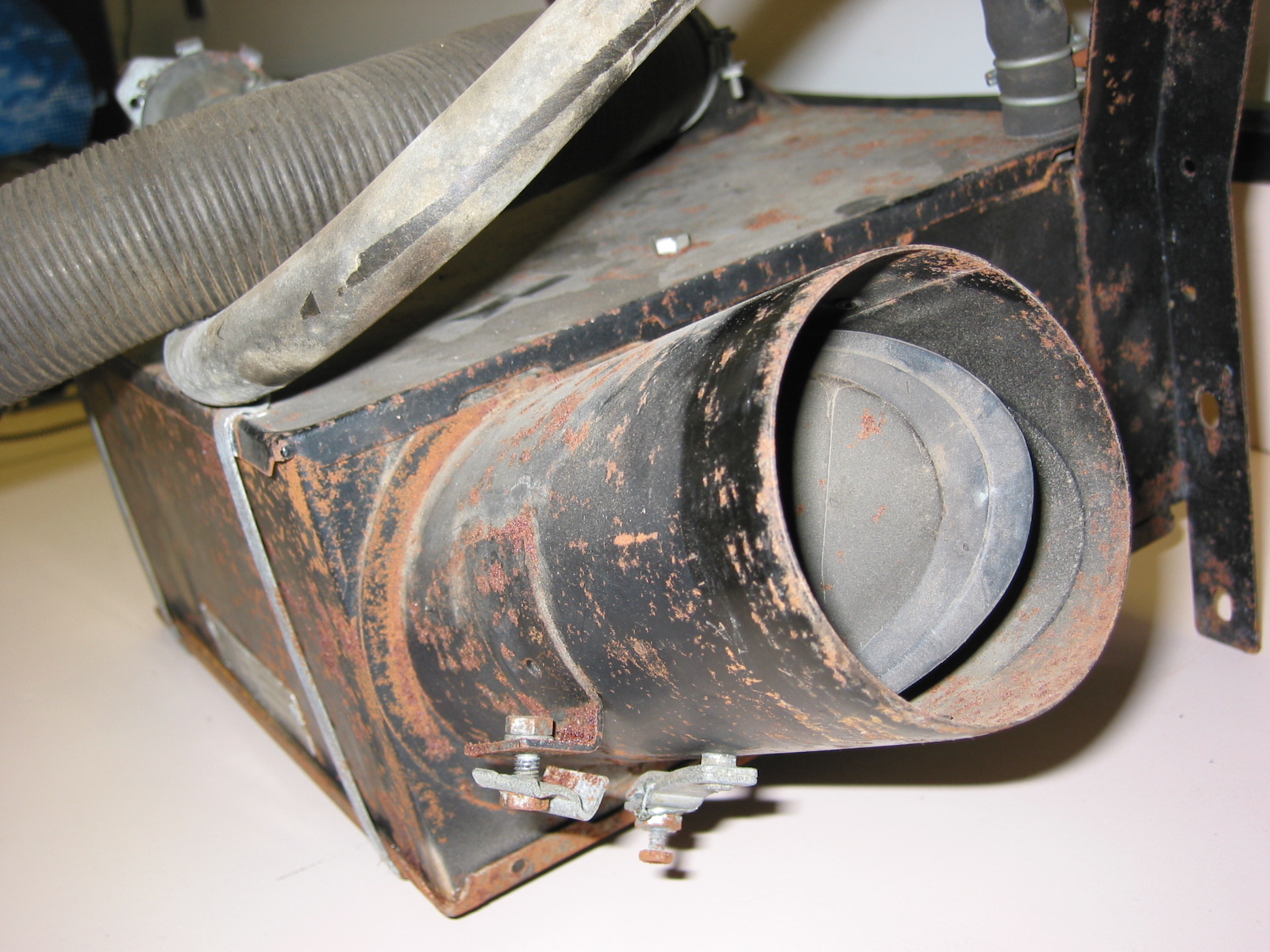
The heater box was painted semi-gloss black, the lower lid clipped to the box with zinc plated spring clips, two in front and one on each side. The heater outlets and flaps were always painted black.
The package tray was supported by a black painted vertical bar. The tray was covered in interior matching vinyl. The inside of the tray was covered with a loose piece of interior carpet.

Healey Blue
Floor boards were covered with 30 pound roofing felt (Tar paper) for noise and heat insulation. An insulating layer of woven jute with a black painted surface on one side was laid on top of the underlay and covered by carpeting. In the footwells in the right-hand side, the panel had a large opening in it. Vinyl was glued to the metal surface.
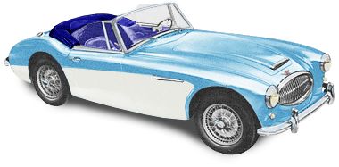
Healey Blue over Ivory White
The carpeting cover over the transmission was removable. It was held in place with snaps like the floor mats. The portion of the transmission tunnel that was visible at the handbrake was covered by a piece of glued vinyl. The door seal was fastened with split rivets from underneath, with the spread legs covered by the seal edge. The ashtray in the transmission tunnel was secured by tow Phillips head 6/32” screws. Seals around the door openings called “draught excluders” were one piece furflex matching the primary interior color and rubber. The upper inside of the door was trimmed with a piece of vinyl. Interior panels were secured with #6 phillips head trim screws with separate cup washers.
Seats
The seat backs were fastened to the set bottoms with chrome acorn nuts holding the seat backs to bolts welded to the seat bottom frames. A chrome washer and a brass washer were installed on both sides of the seat back. The seat bottom frames themselves were covered with narrow strips of vinyl glued over the edges of the frames with the overlapping ends at the rear of the frame.
Florida Green
The seat bottoms were bolted to studs welded into sliding rails, which in turn were set on 5/16th” thick wood packing strips. These strips rested on large rectangular black-painted metal strips that rested on the tarpaper and jute felt were cut to go around the seat strips. Seat rails were secured to the floor with studs that extended through the floor, held in place by shouldered nuts with flat and lock washers that centered the seat bolts in the floorboard holes.

Florida Green over Ivory White
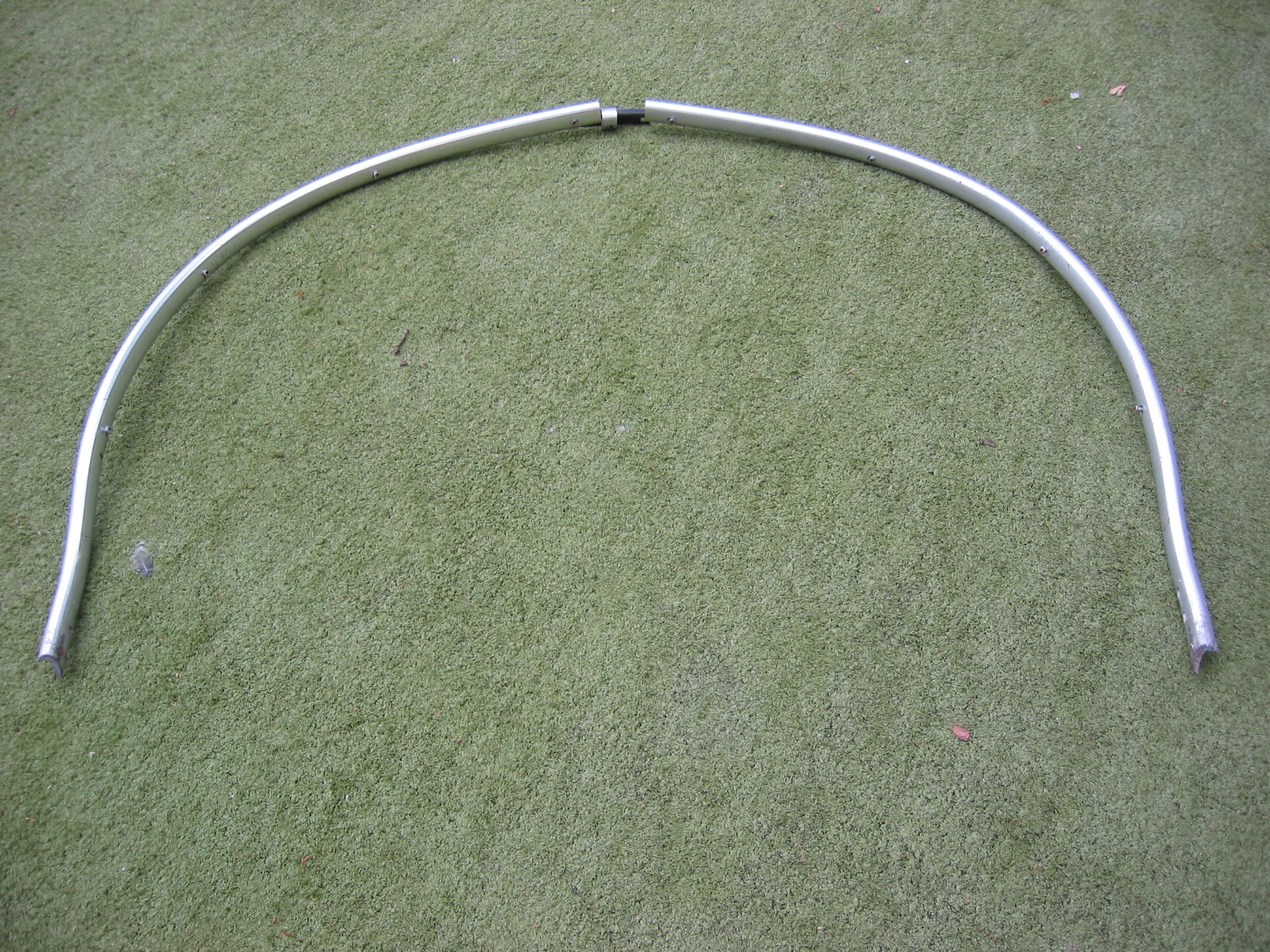
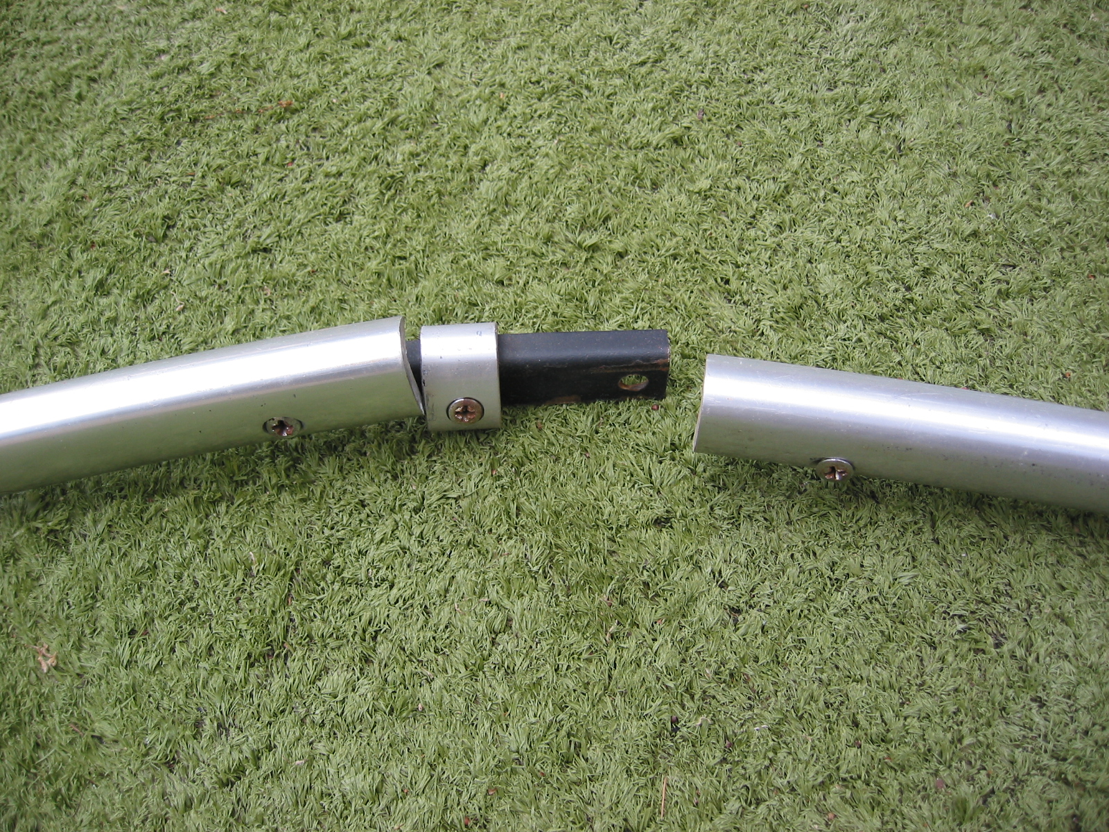
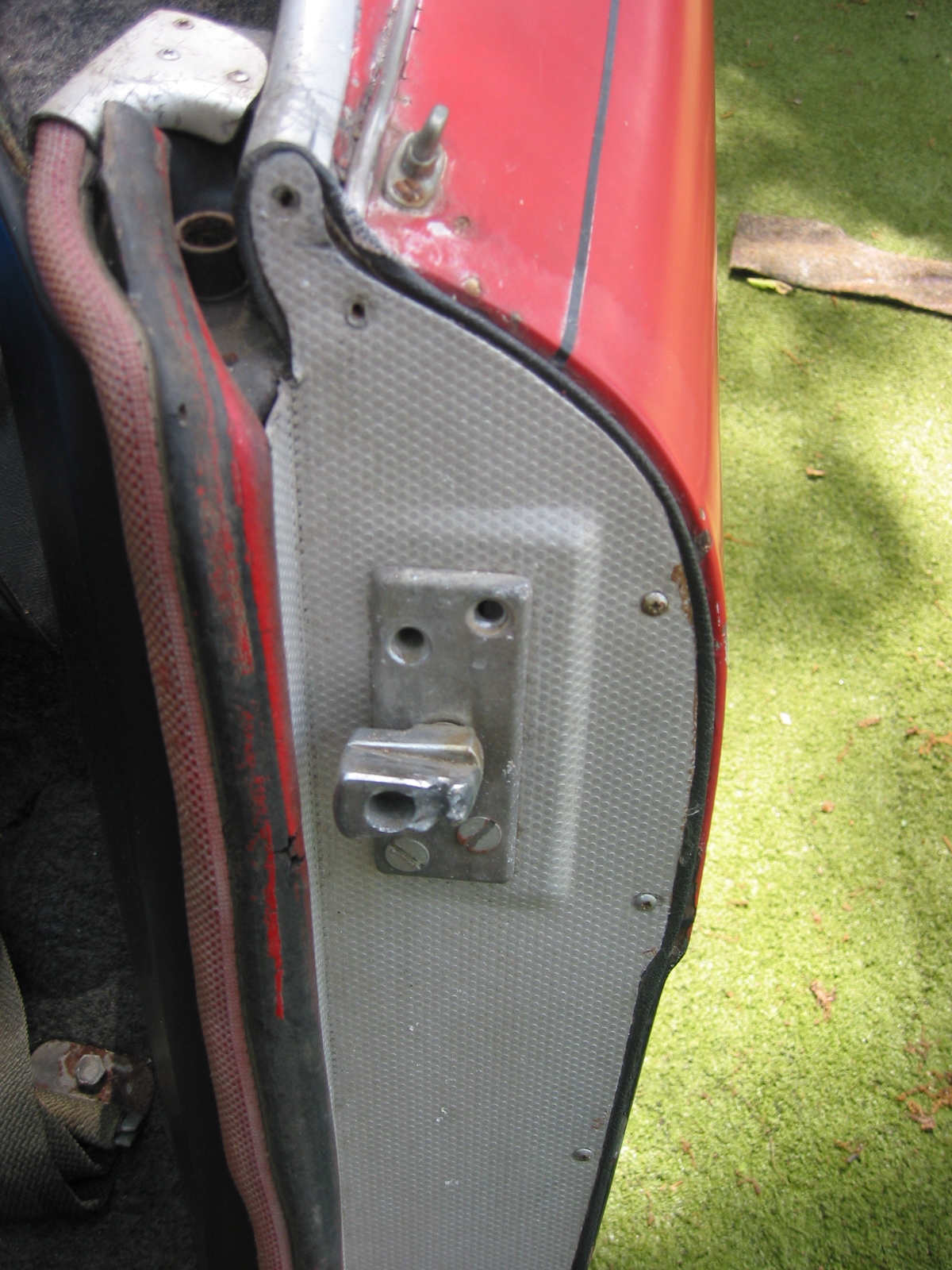
Soft Tops
In all cases, the soft tops were made of Everflex vinyl in grey, black or blue. The underside was a soft gray color. The vinyl top was fastened to a wooden front bow. The soft top frame mounted onto holes on the inner fender well that held the tonneau cover support.
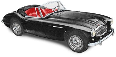
Black
Hard Tops
The optional tops came in ivory white, black, Colorado red, florida green, and healey blue and were usually ordered to match the side panel color of the car.
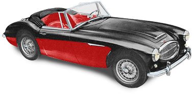
Black over Colorado Red
Seat Belts
Three point seat belts were available as factory options on the 3000s, and were supplied with all equipment required for mounting.

Black over Ivory White
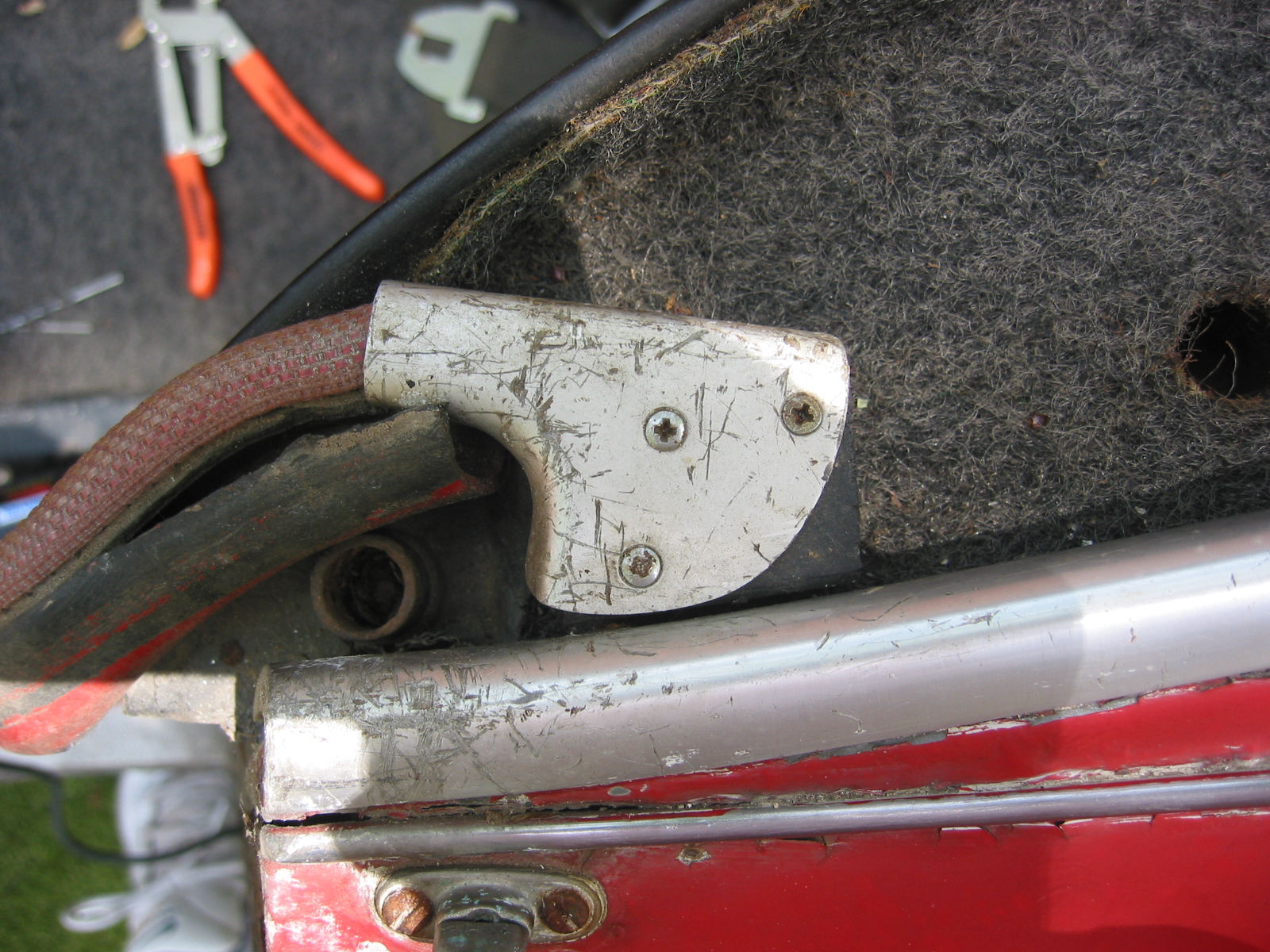
Trunk, Tools, and Loose Equipment
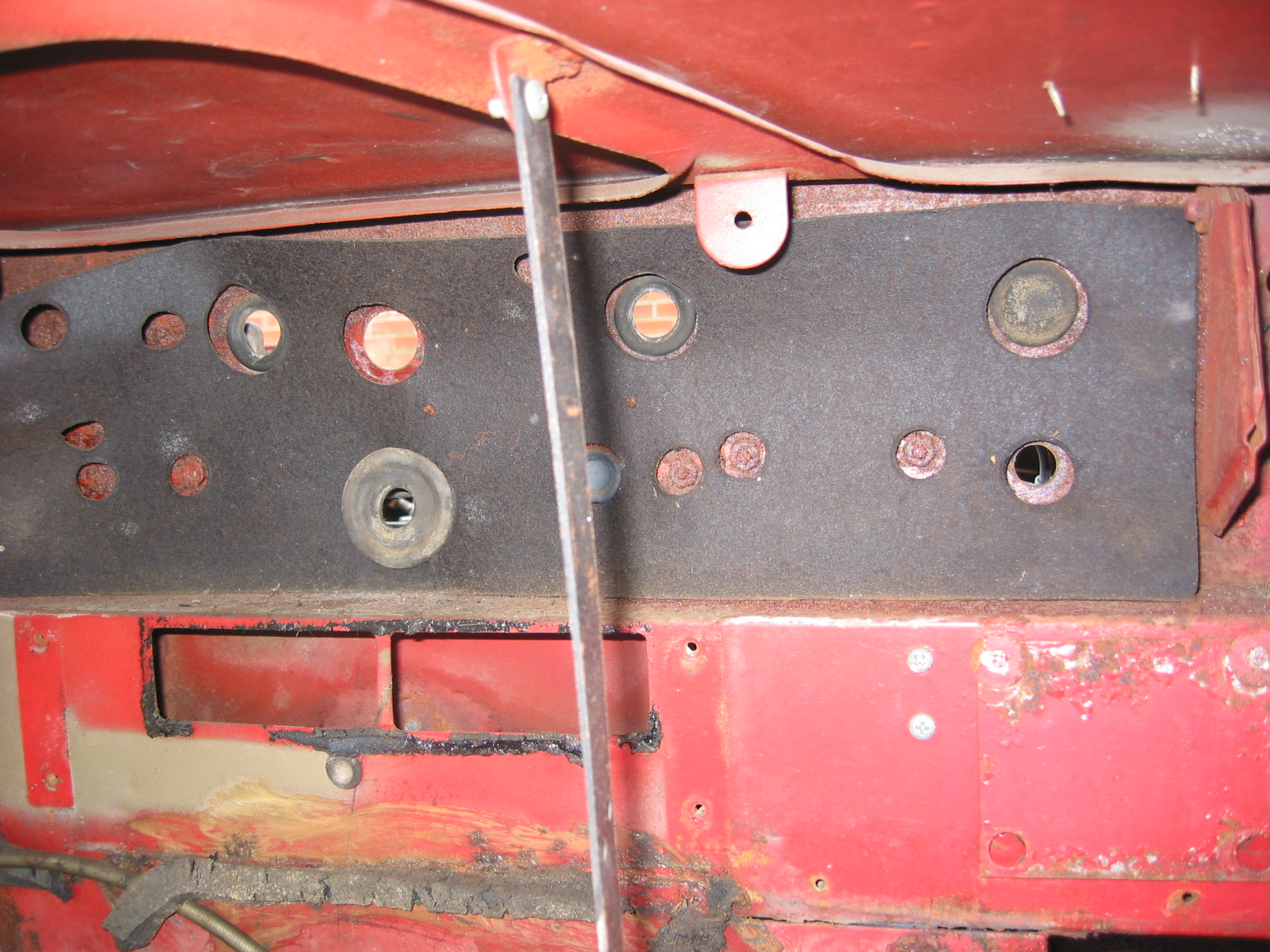
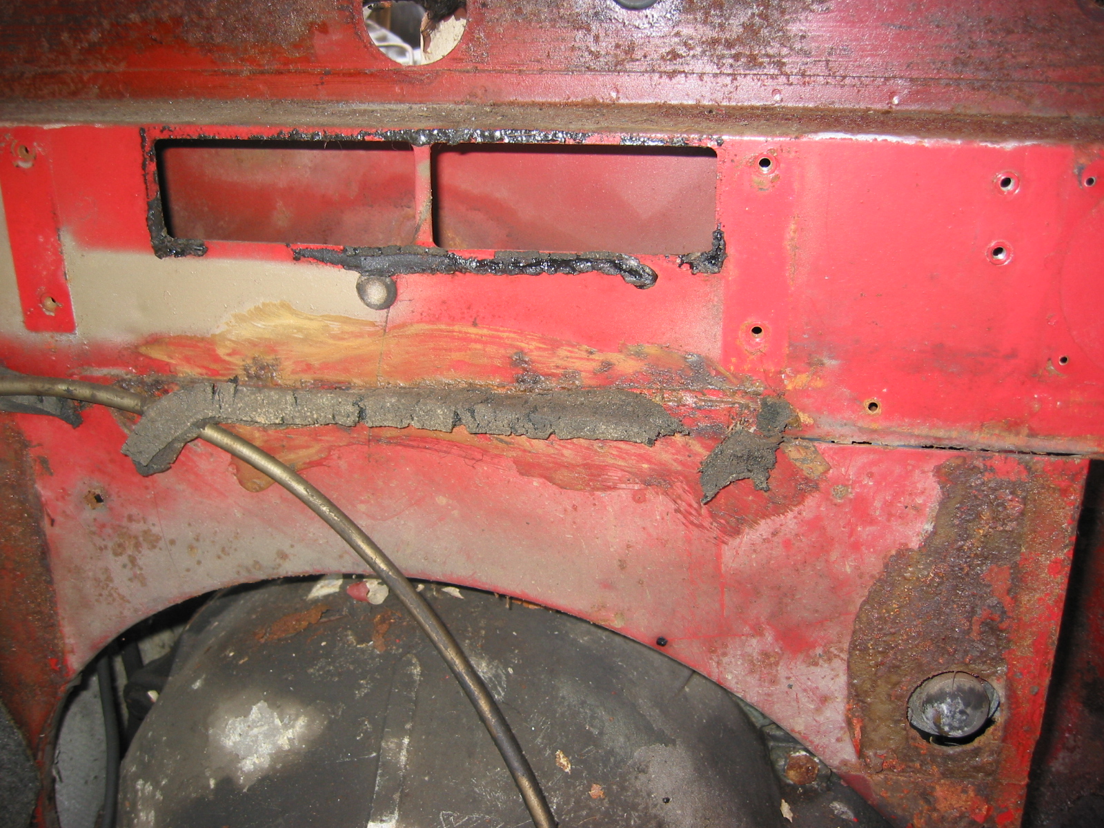
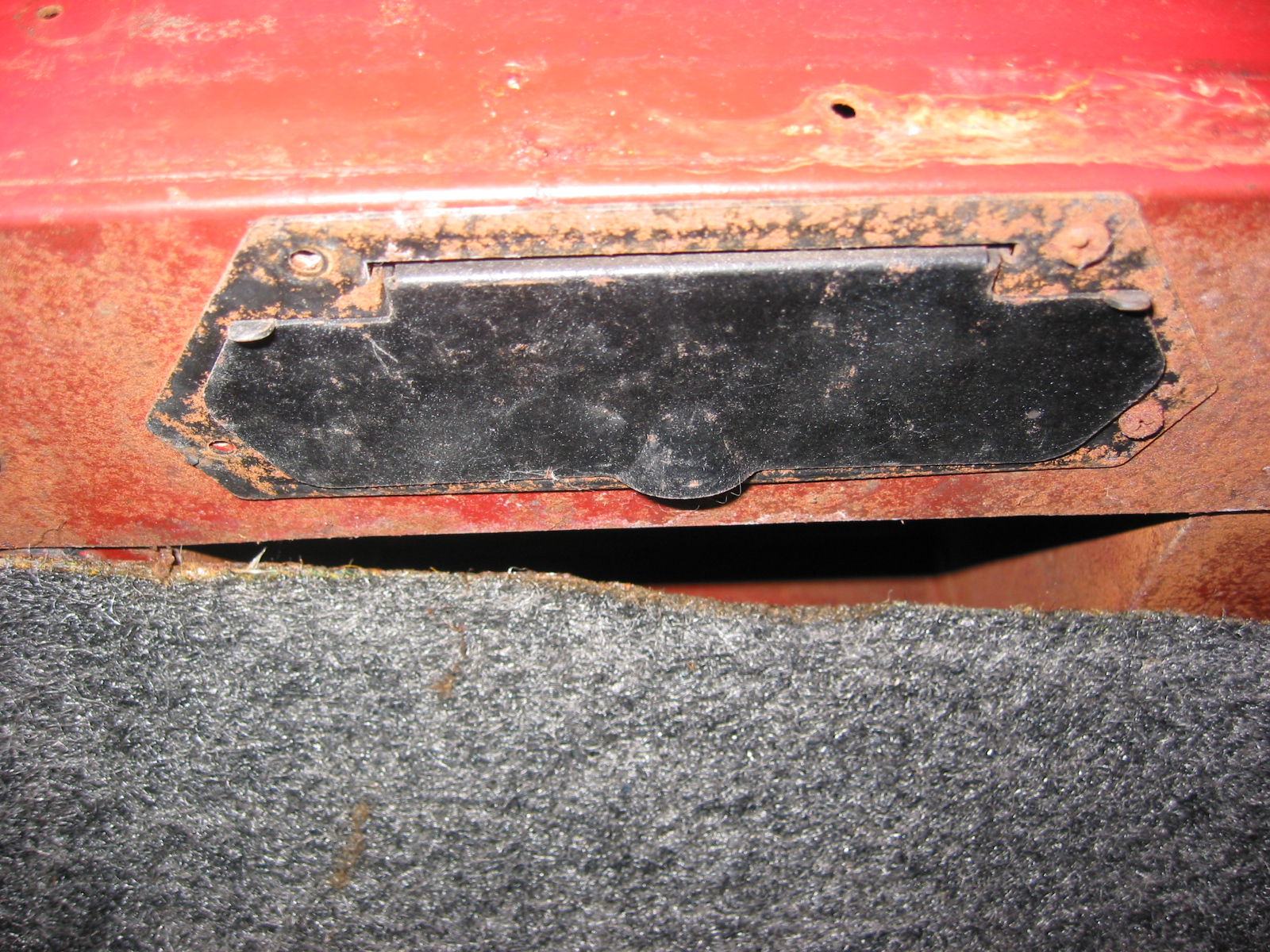
The trunk lid was the same on all six cylinder roadsters. The locking mechanism was painted body color. The metal catch was also painted body color as it was apparently mounted before the car was painted. The prop rod for the trunk was painted black. The interior of the trunk was covered with Black Armacord, a ribbed vinyl material with jute backing. The Armacord was glued to the vertical bulkhead and to the fender surfaces. It was laid loosely on the floor and on either side of the trunk. The Armacord on the rear bulkhead was additionally secured by six pop rivets without washers, three where the bulkhead curves back (one hidden by the fiberboard filler pipe cover) and three in the inch-wide section at the very top of the bulkhead. The black leather grained fiberboard partition that covered the fuel filler pipe was fastened with Pozidrive trim screws and cup washers to the bulkead and inner fender wells.
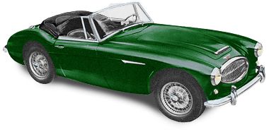
British Racing Green
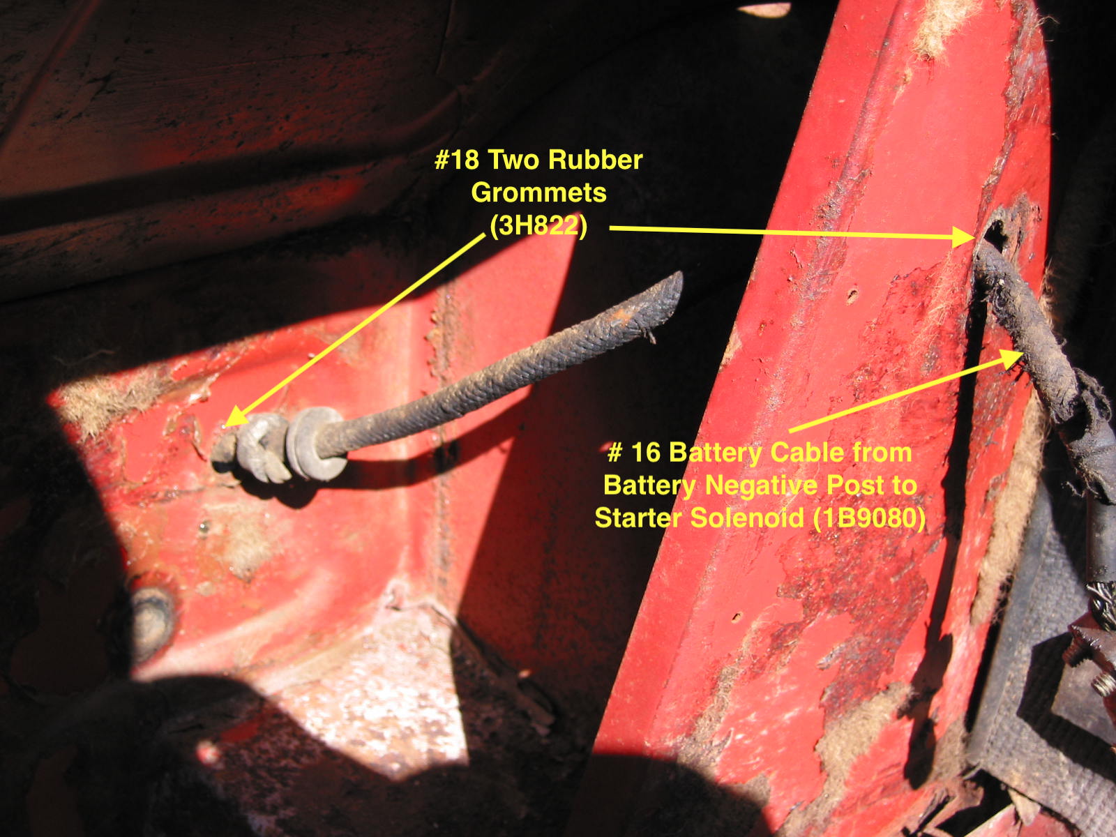
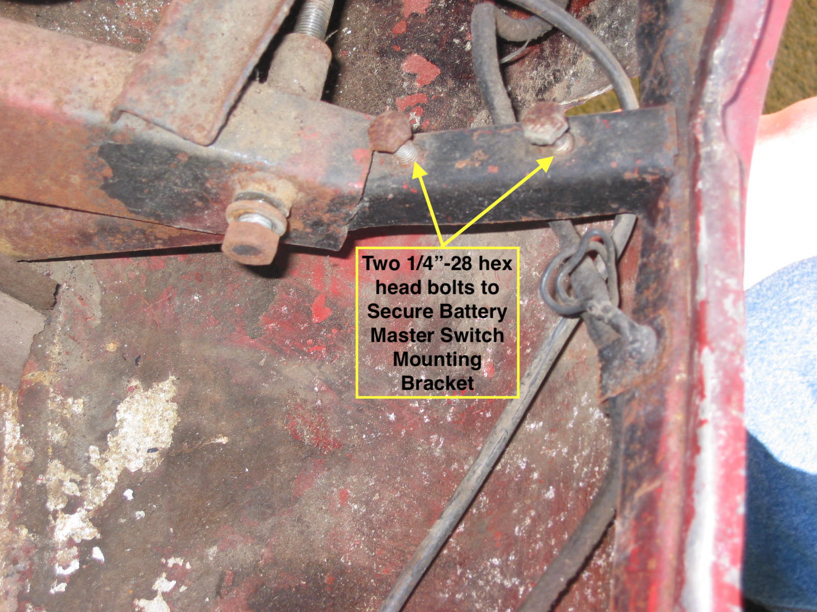
The battery rested in a heavy plastic tray and was secured by two threaded battery hold-down rods that hooked under securing points at the bottom rear of the battery.
Along wooden block was mounted to the inside surface of the right rear quarter panel to brace the battery against the hold-down bracket.
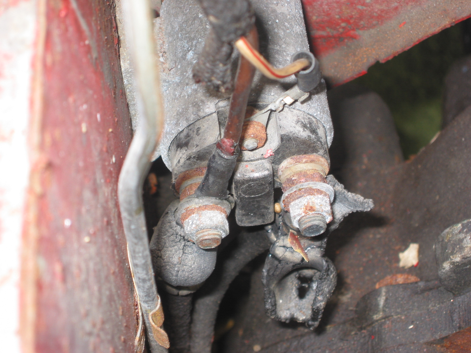
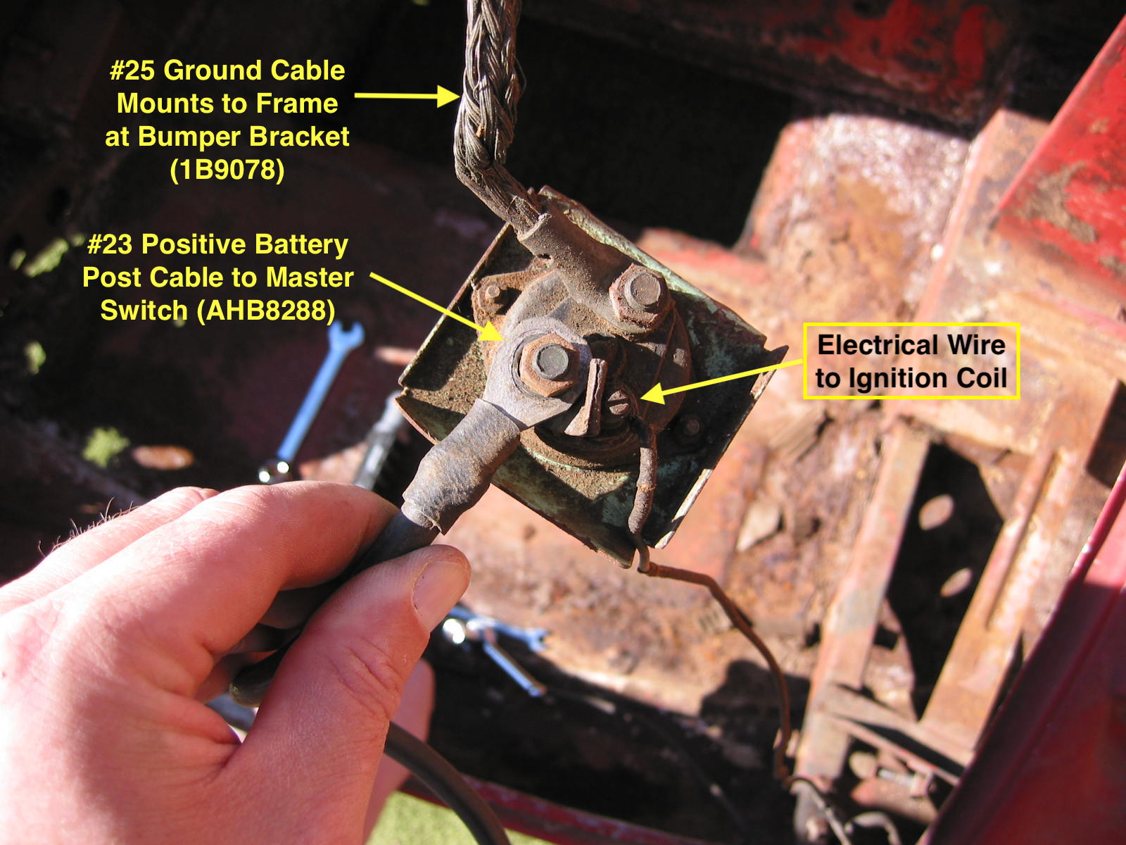
A switch in the trunk was used to break the current flow. The connection between the ground and the battery was cut off, and the distributor was grounded out so even if another battery was used the car wouldn’t start.
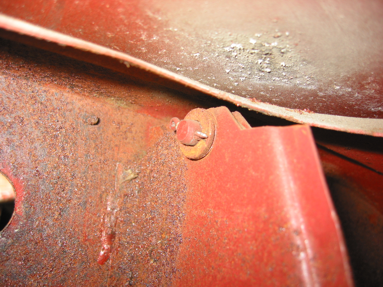
The spare tire rested on the floor of the trunk against two black vinyl covered wooden blocks, one bolted to the left inner fender and one bolted to the bulkhead with unpainted bolts and washers. A black painted metal rod with a D-shaped loop on the other end extended over the tire to hold it in place. The rod was secured by a black leather strap at the rear approximately 1” wide. A vinyl side curtain bag in black with a centerdividing panel was provided. A jack and a minimal tool kit was also provided
Ivory White
Engine modifications from the 100-6
The BT7 engine was bored from the 2,639 of the 100/6 to 2,912cc; horsepower was increased from 117 to 124bhp with 1.75” SU HD6 carbs, standard needle was CV. Cylinders increased from 79.4 to 83.36 bore. Stroke unchanged at 88.9. Compression up from 8.5:1 to 9.0:1. Valve timing was 5/45/40/10. Normal oil pressure was 50 lbs at 40mph. Normal running temperature was 175-190 – thermostat was set at 154 to open. Radiator had 12 gills per inch starting in 12/59.
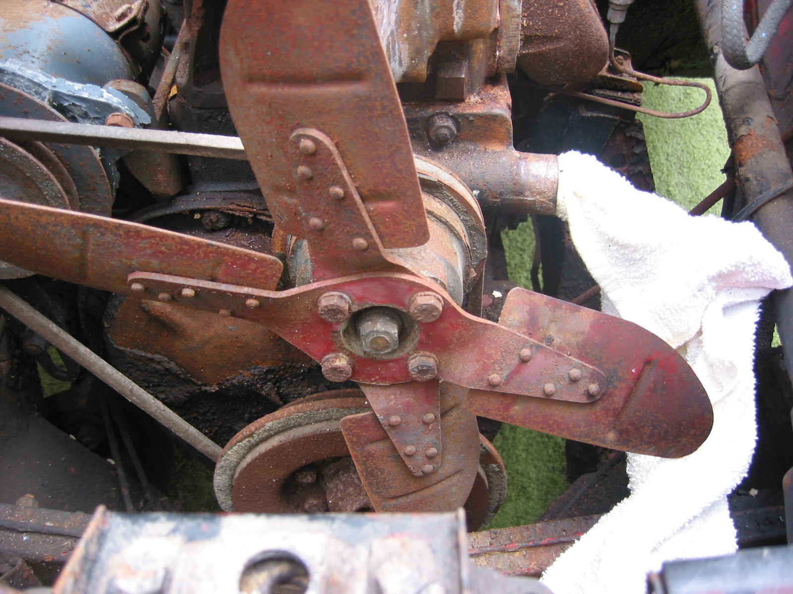
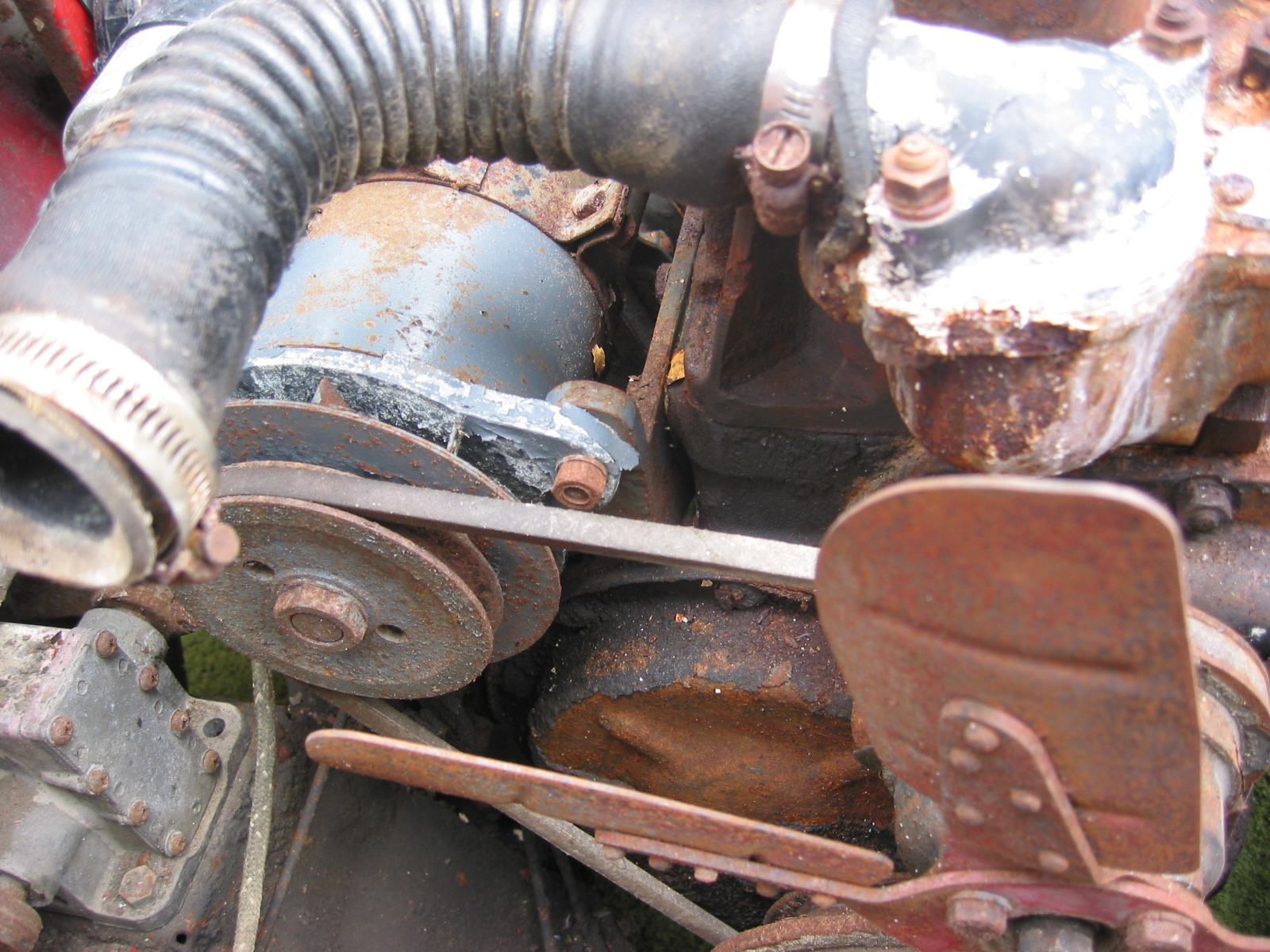
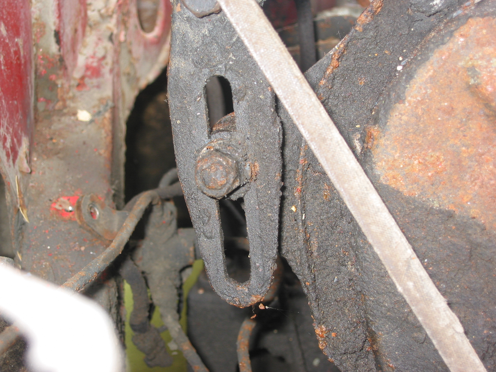
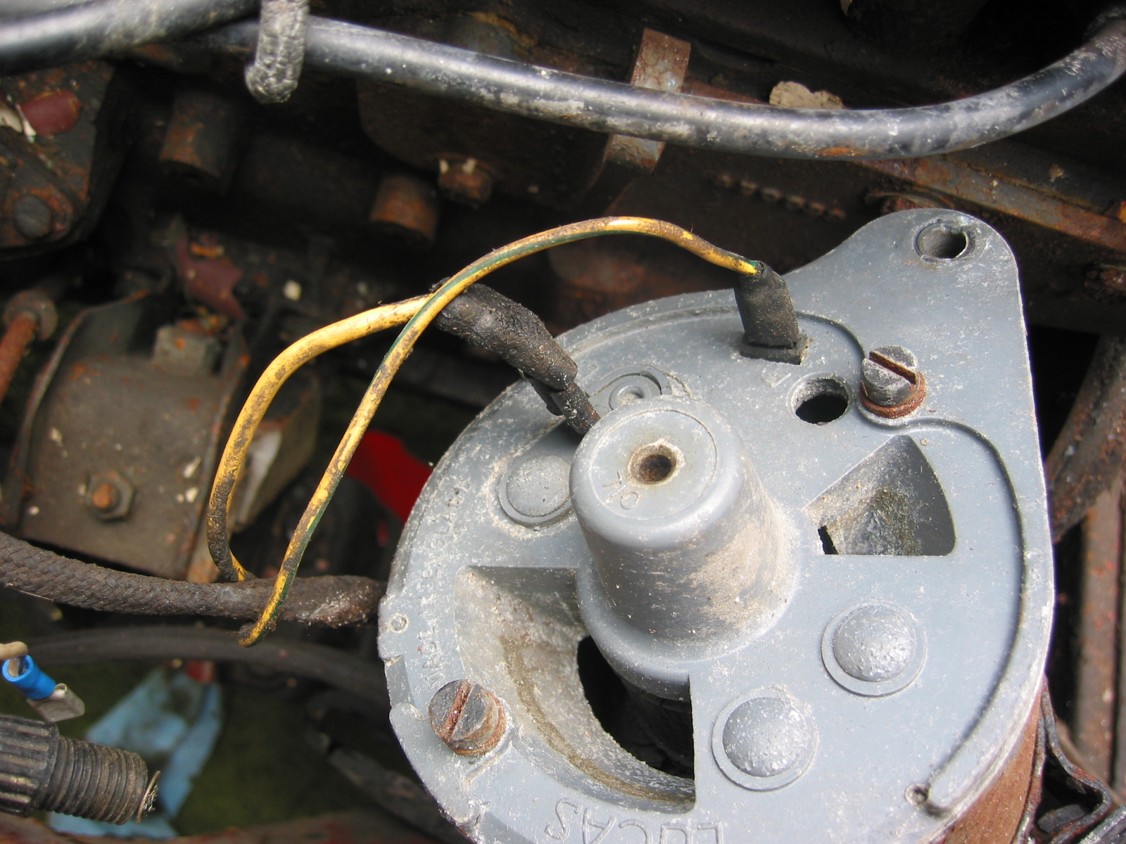
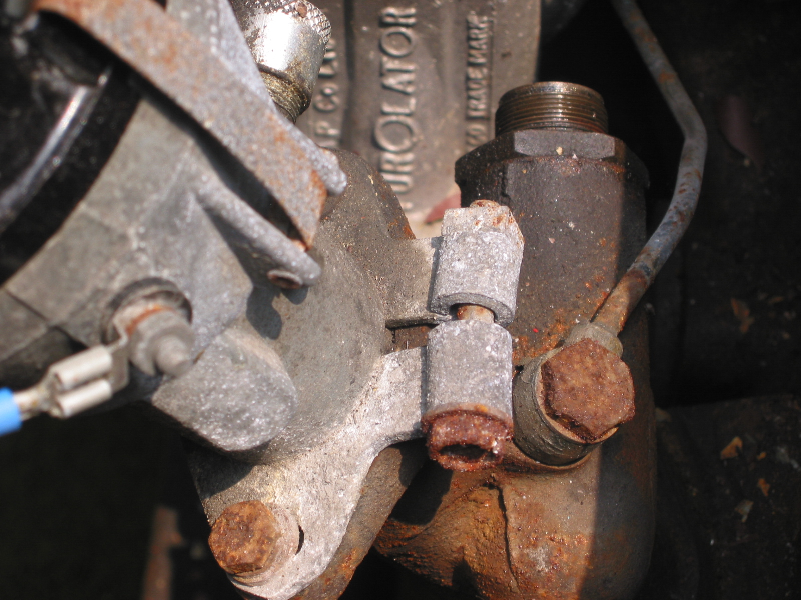
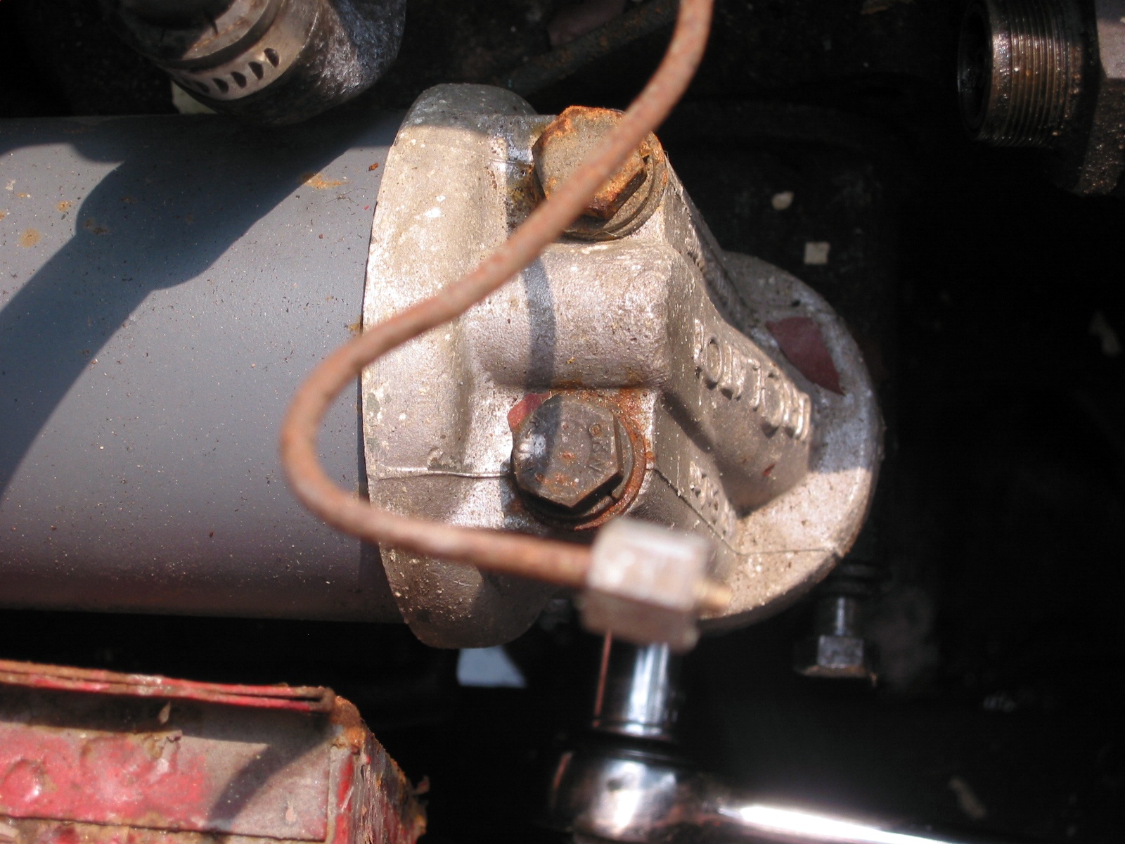
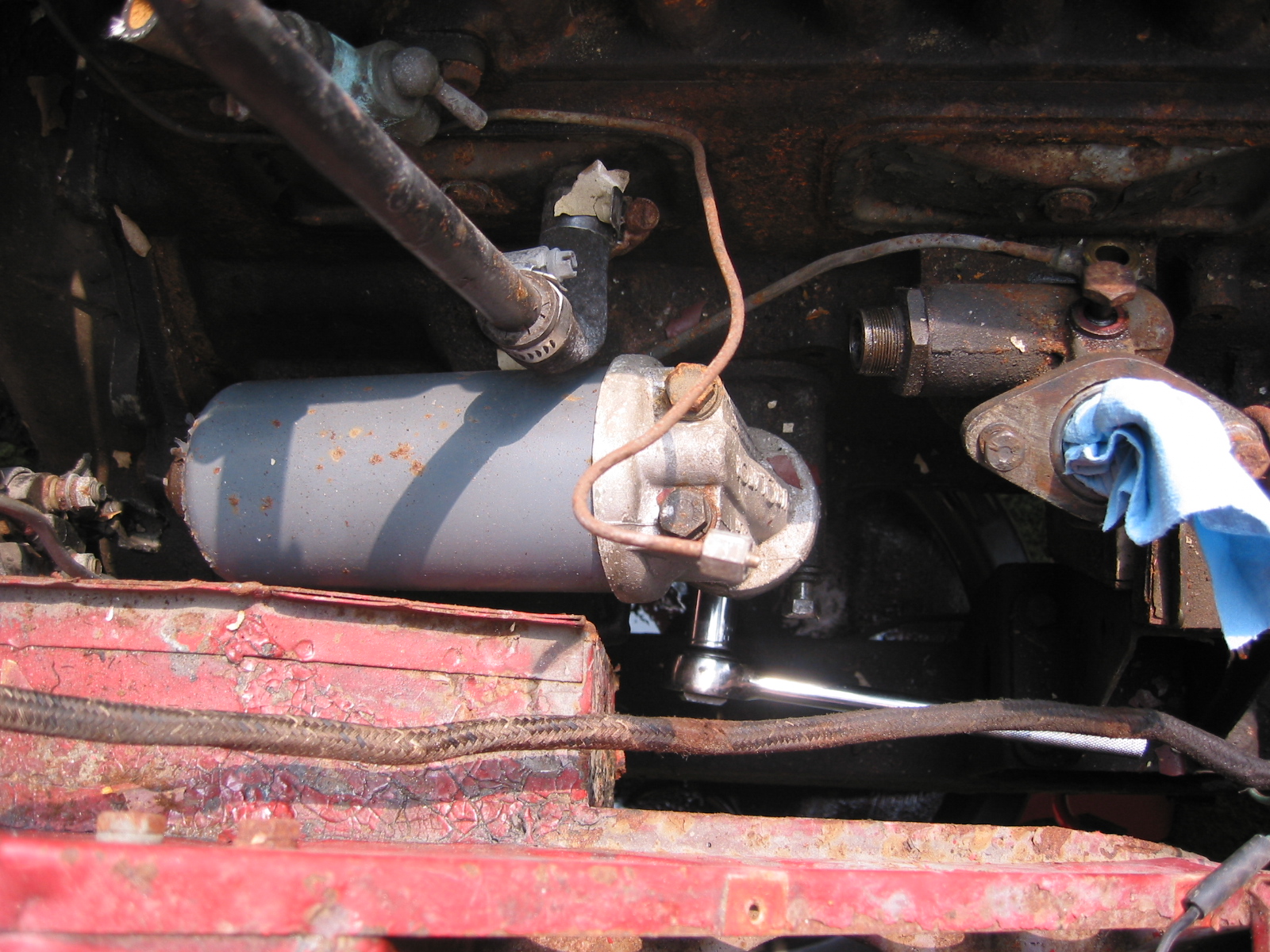
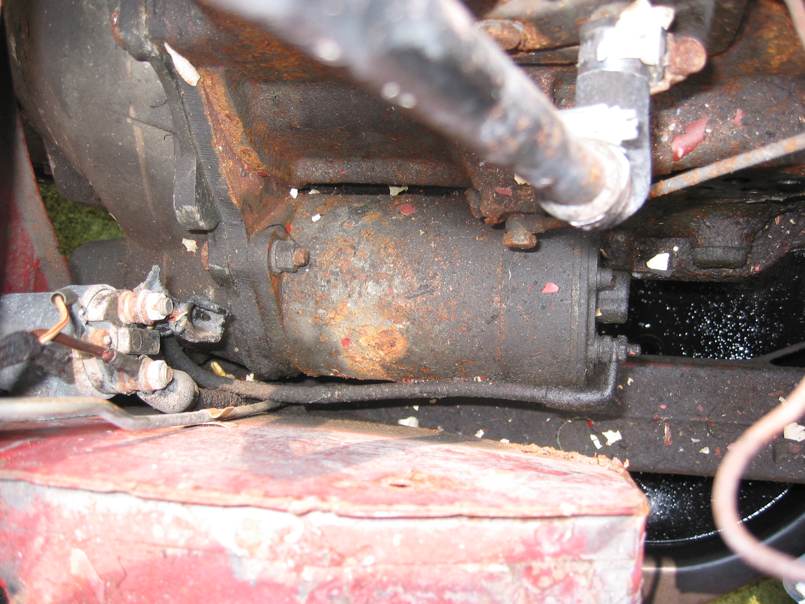
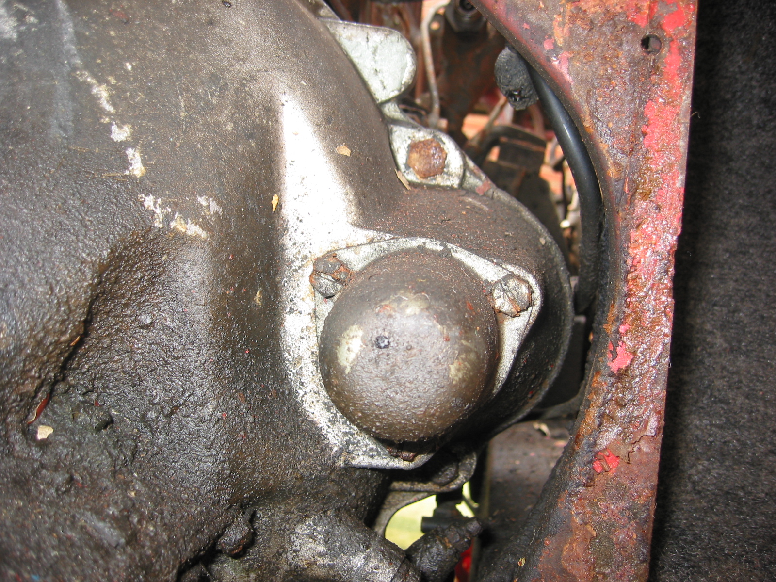
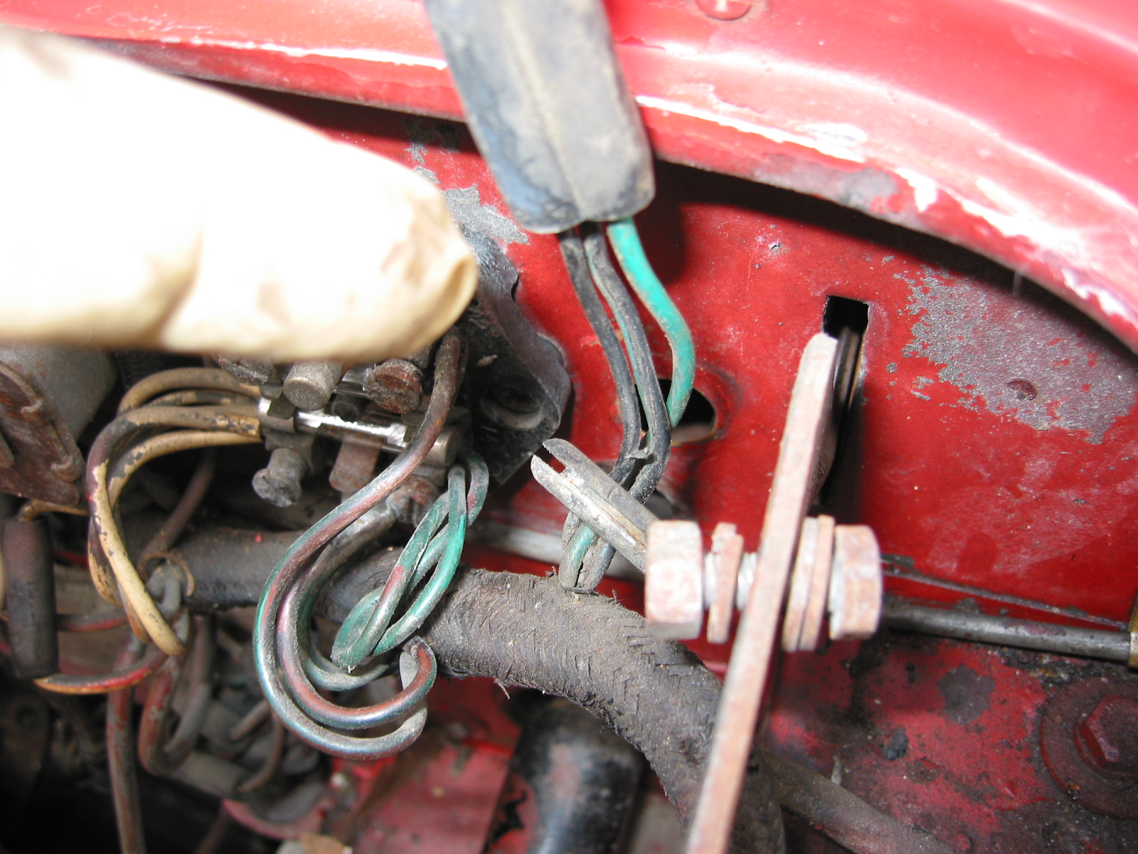
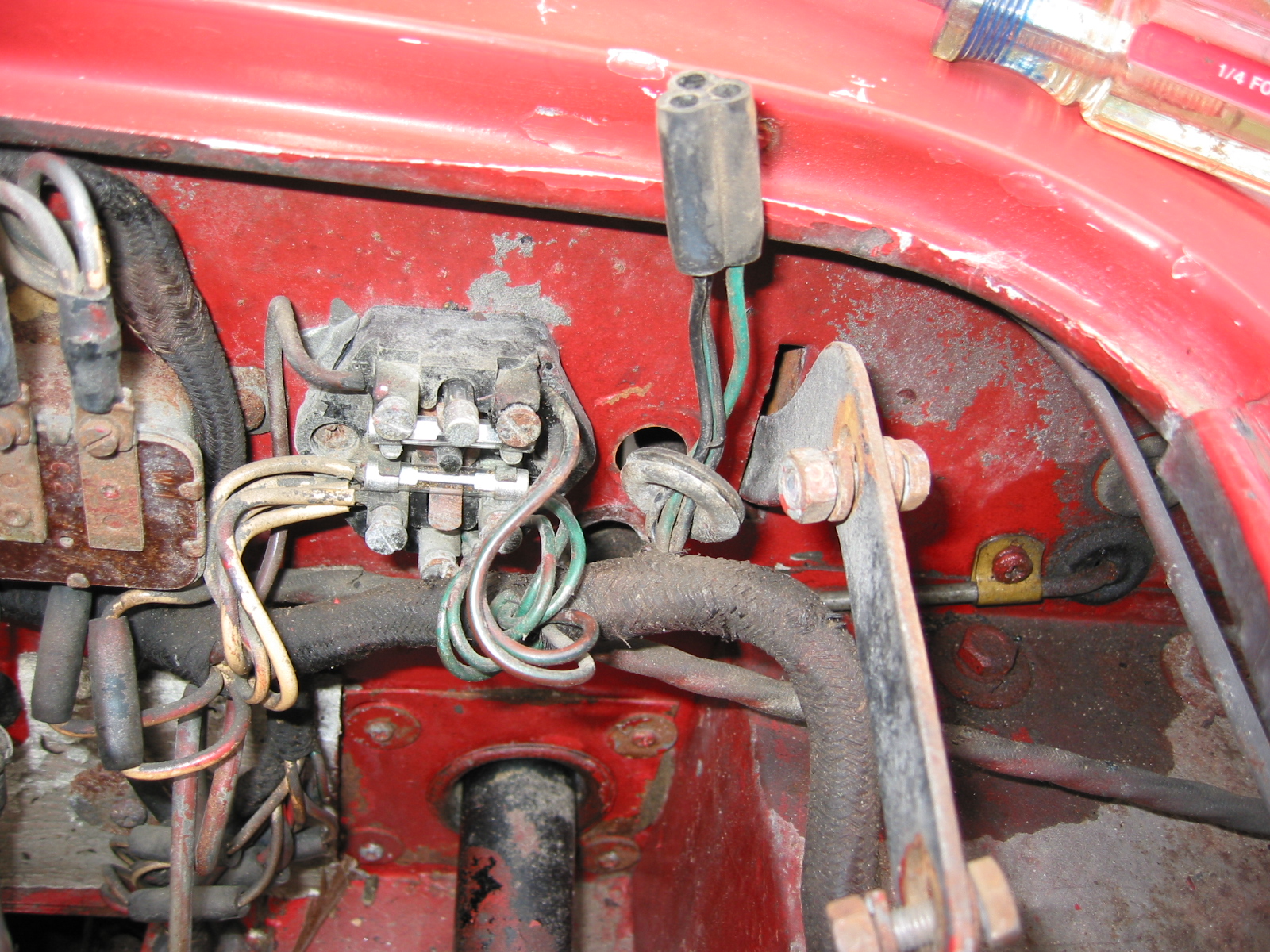
The engine identification plate was mounted with drive pins or drive screws, then painted with the engine. Fan belt was flat, no teeth, 3/8” wide. Generator was a Lucas (c45pv6) #22530 A or B with push or blade terminals. Mounting bolts were with heads outboard and washers and nuts inboard. Oil filter was Purolator or Tecalemit. The temperature capillary tube was clipped to separate stand off brackets, which were secured under the same studs used to secure the heater return pipe brackets, painted black or green. The capillary tube was formed into three 1 1/2” diameter coils just in front of the firewall. Starter was an L3M48G
Ignition System
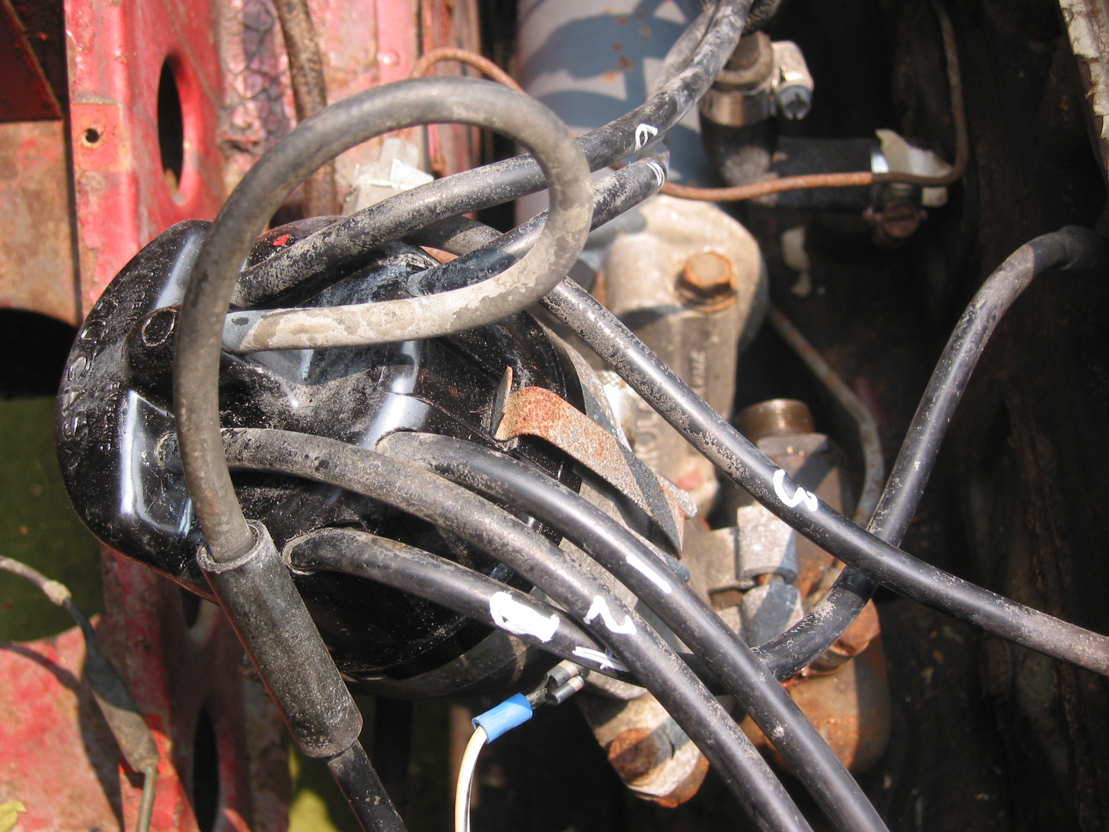
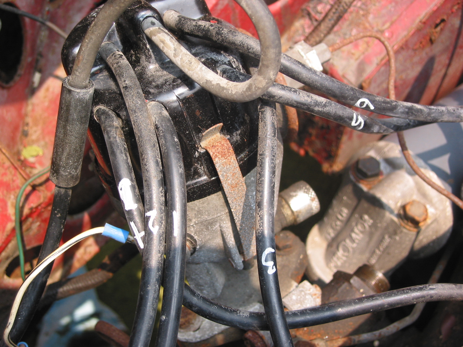
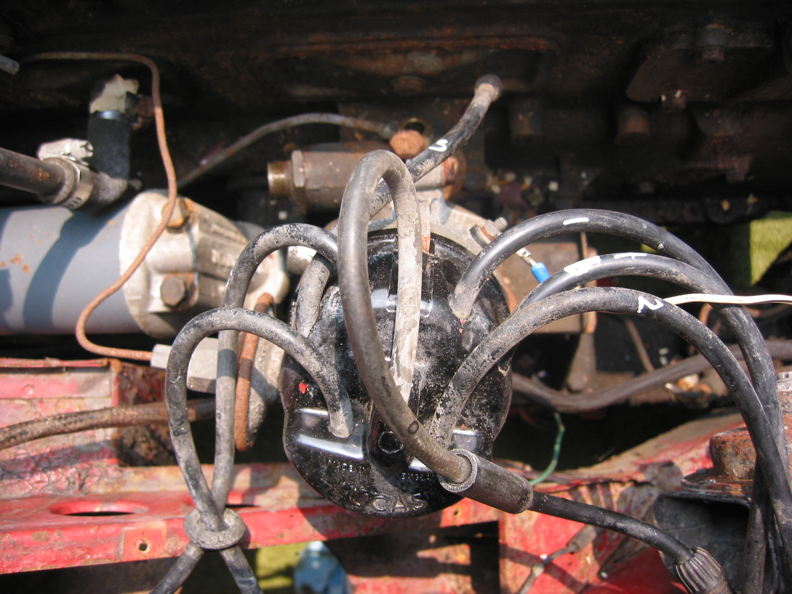
The spark plug wires to the 1st and 2nd cylinder, those to the 5th and 6th cylinder were gathered together between the distributor and the engine with black rubber O rings about 7/8” in diameter. Champion 14 mm 3/4” reach with .025 gap spark plugs were used. N5C or N3 competition plugs were sometimes substituted. The ignition coil was Lucas HA12 “Heavy Duty” aluminum body with black head. The month and year of manufacturing were stamped on the base. The mounting strap around the coil was zinc plated. Firing order was 1,5,3,6,2,4 on all cars. Control box was RB106/2, distributor was DM6A.
Ivory White over Black
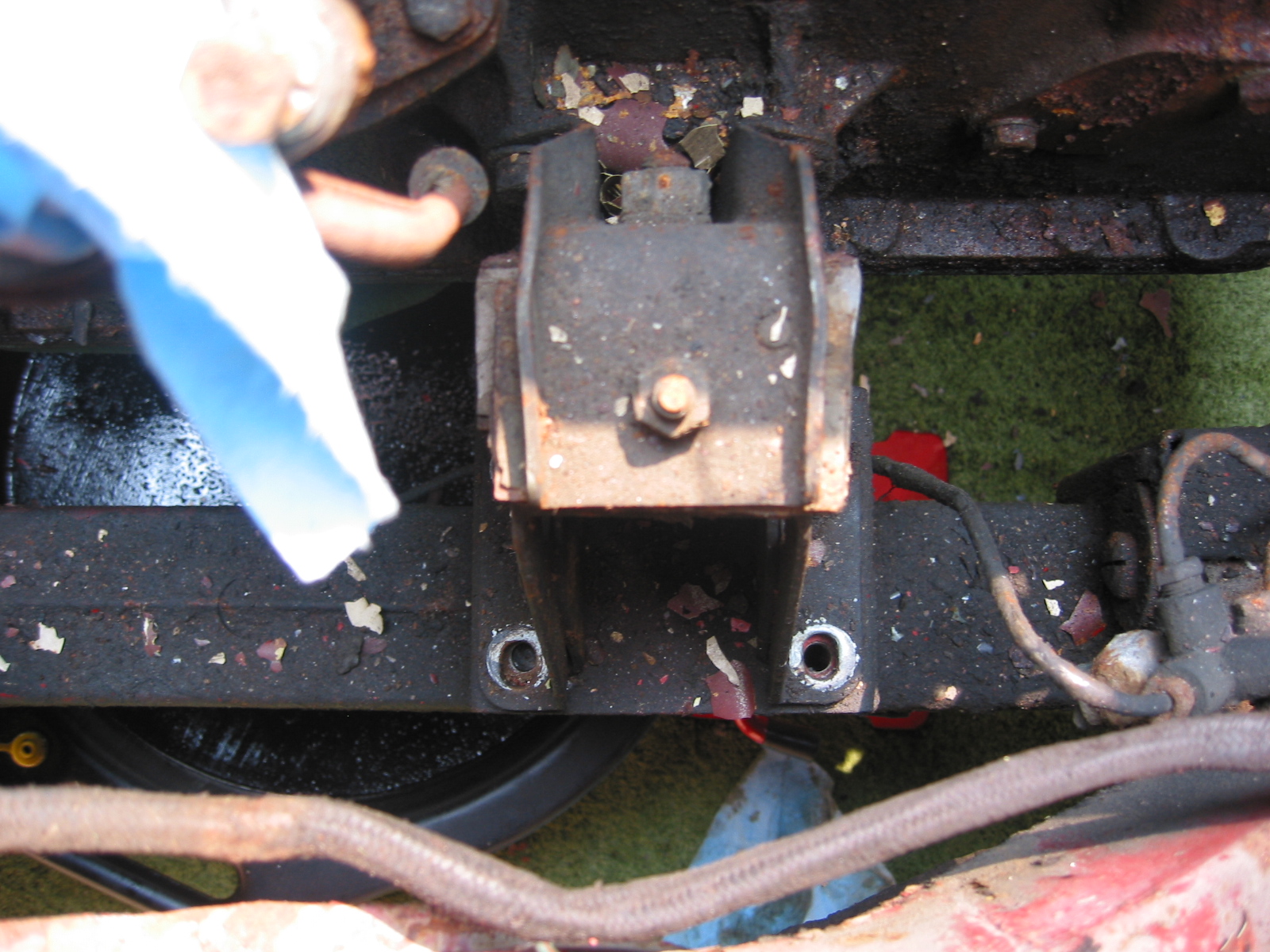
Suspension
Shocks were armstrongs type IS9/10RXP in front and DAS9RXP in rear. Castor was 2,” the canter angle was 1” and the swivel pin inclanation was 6 1/2 degrees. The rear end ratio is 3.9.09:1 with overdrive.
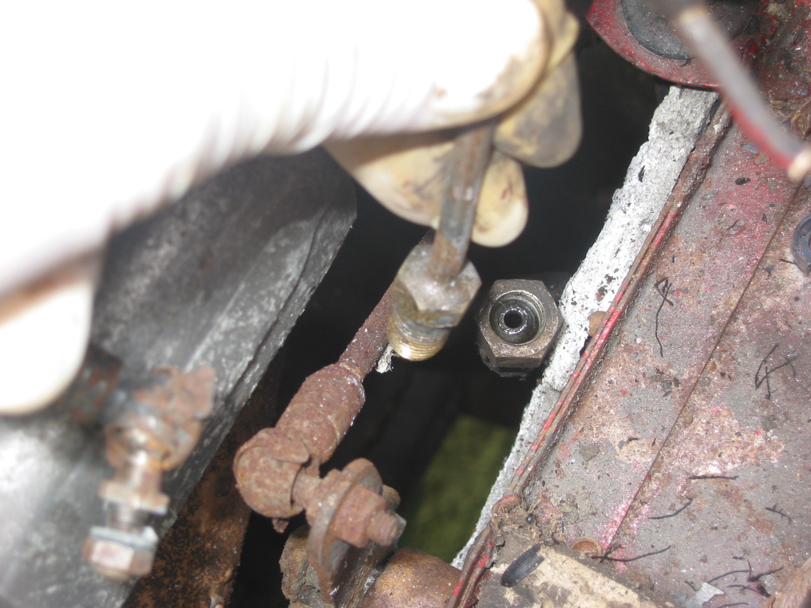
Brakes
11” Girling disk brakes in front. In March 1960 c#9088, Black painted backing plates were added to the disks. 11” Drum Brakes in Rear. 2 1/4” wide linings. Brake lines were 3/16” zinc plated unpainted steel tubing.
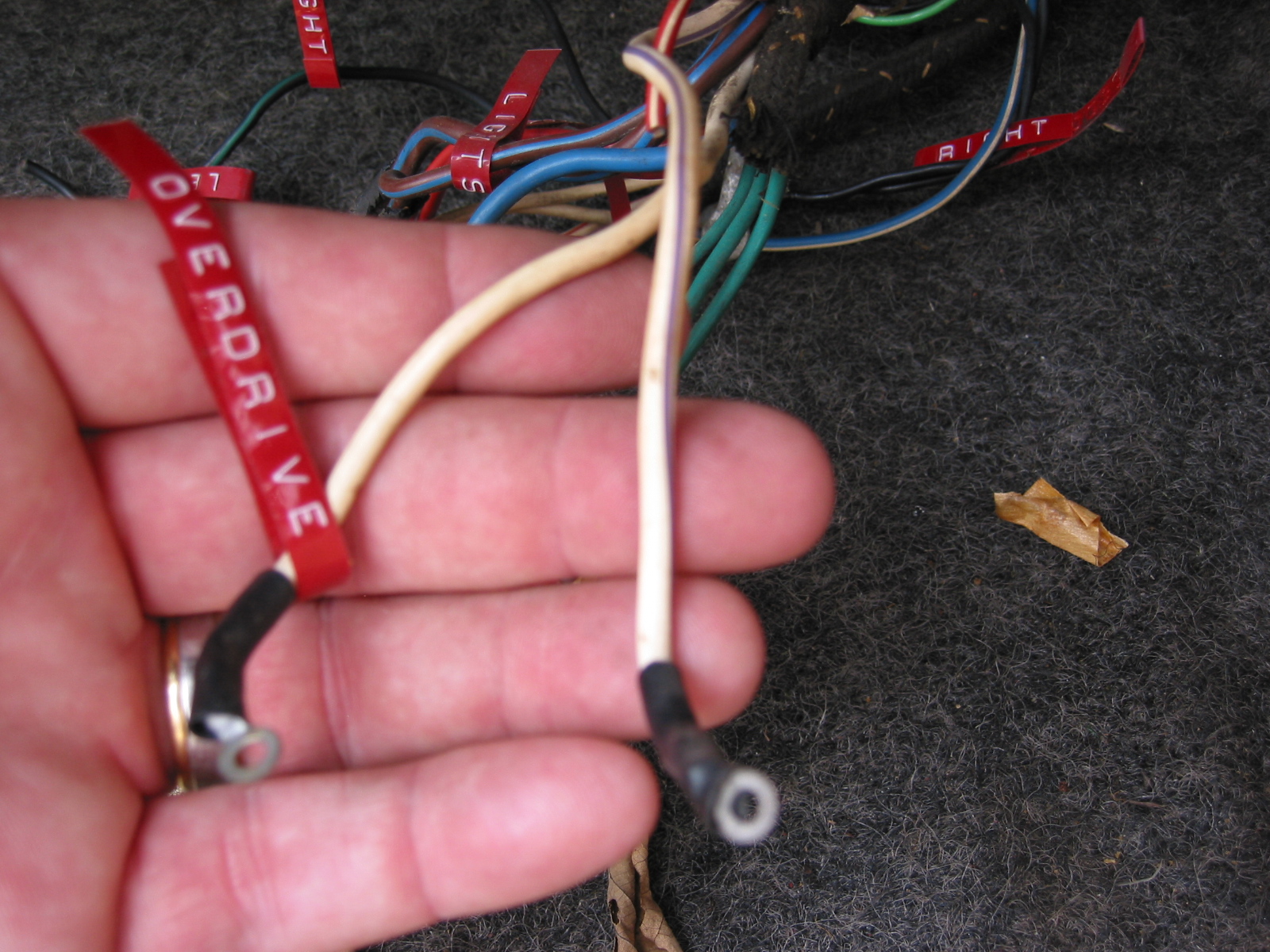
Transmission, Overdrive, Clutch
10” Borg and Beck Clutch. In November 1961 the switch was made to the center shift transmission and fiberglass tunnel. Gearbox ratios can be found on page 61 of the Original Austin Healey.
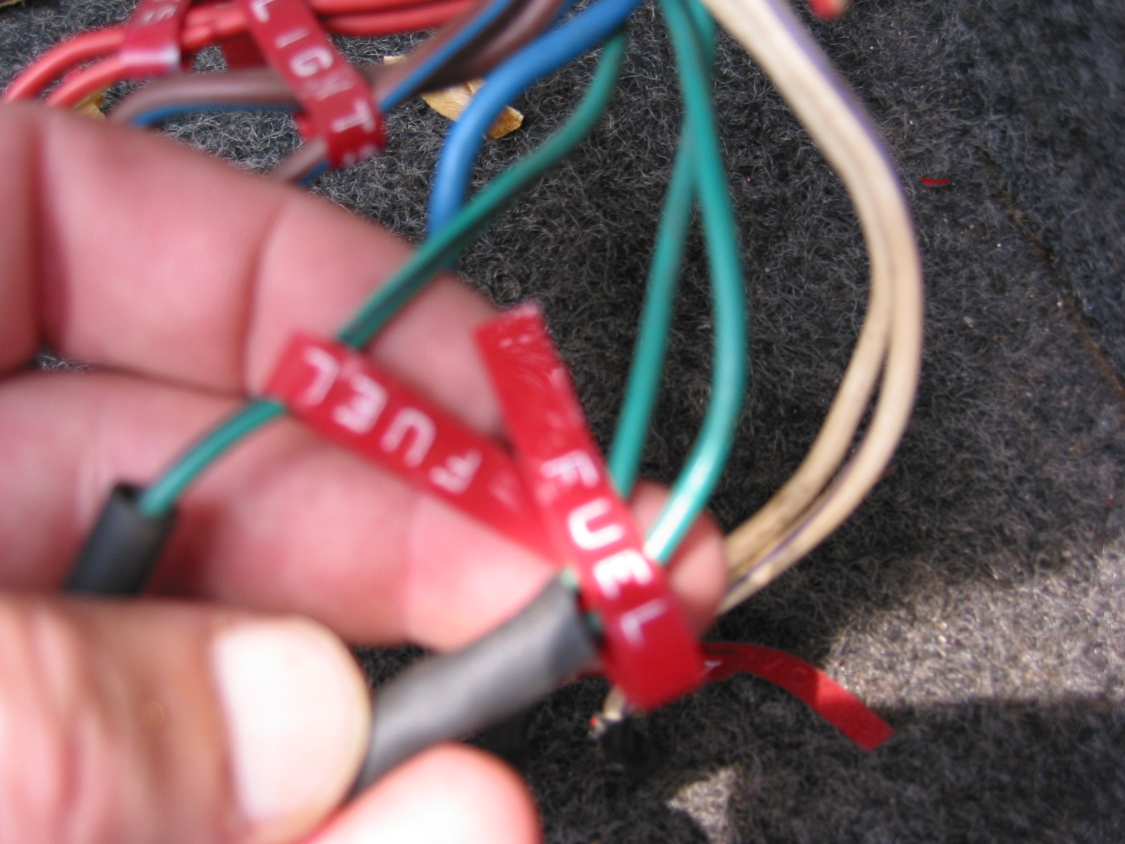
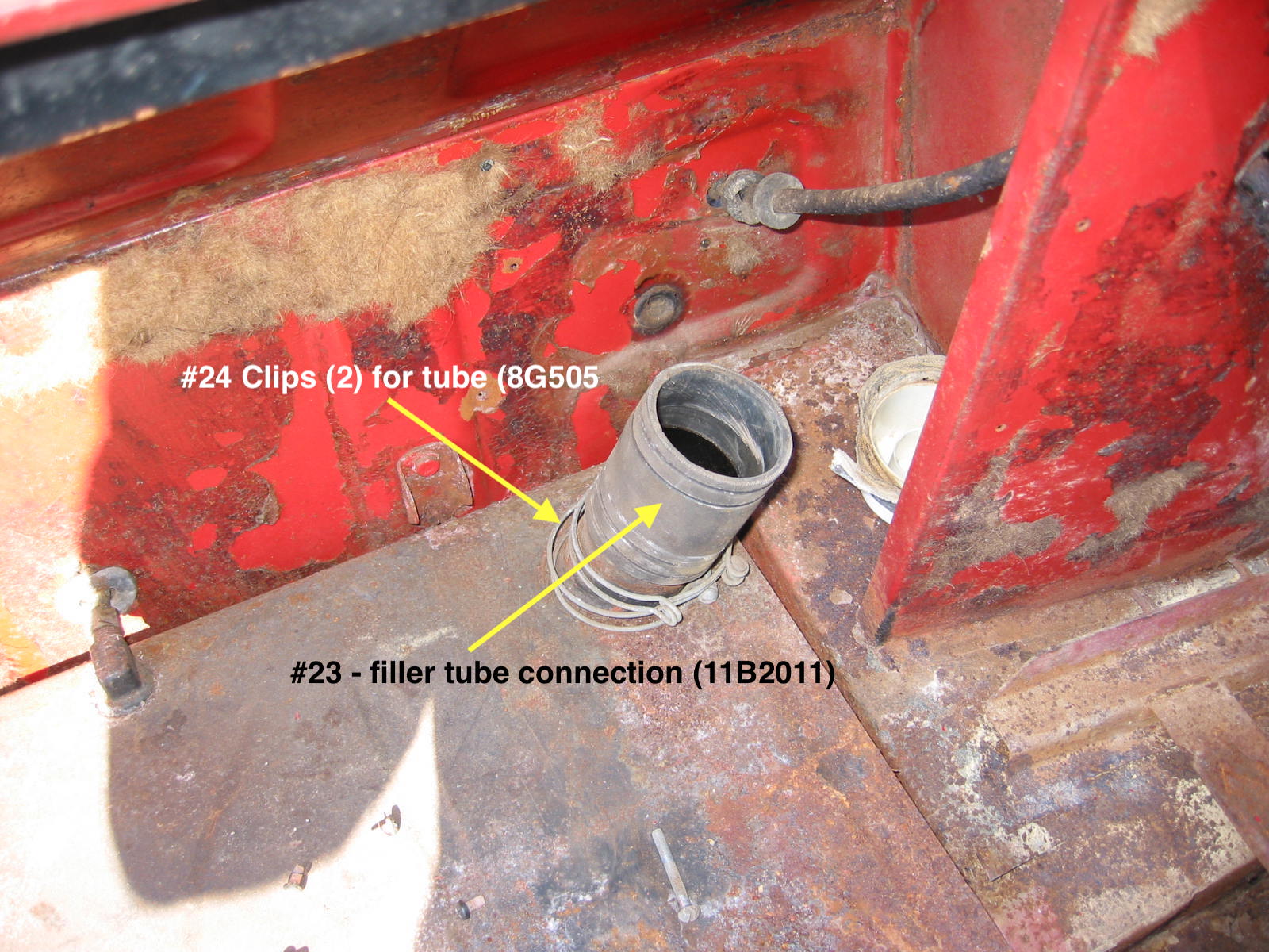
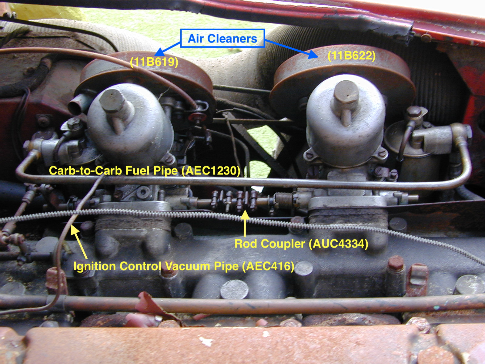
Fuel Pump and Fuel Lines
AUA72 was the fuel pump used on the MK I. The MK II moved the pump to the right side of the car away from the heat of the muffler. Fuel line is zinc plated 5/16” steel line.
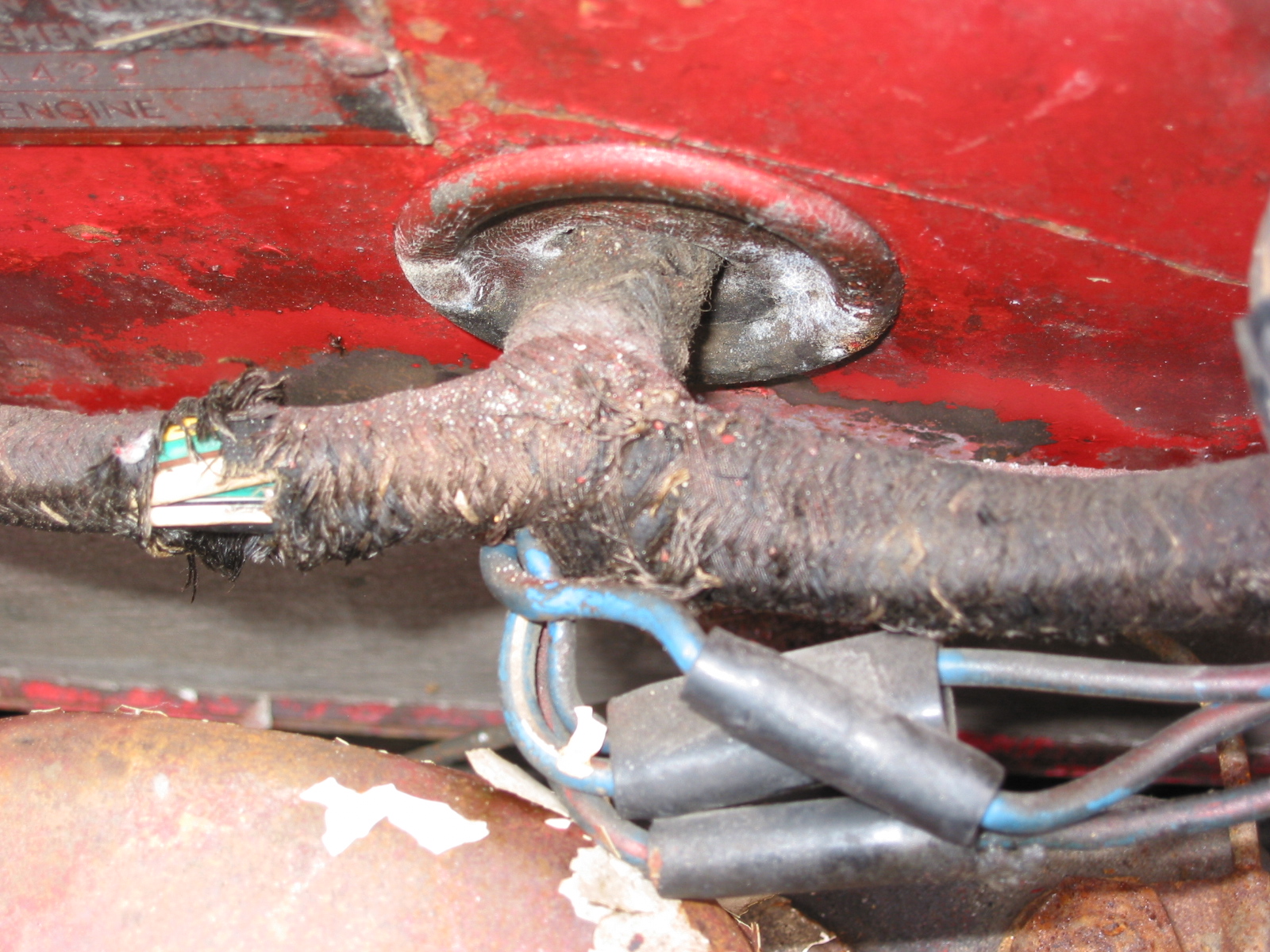
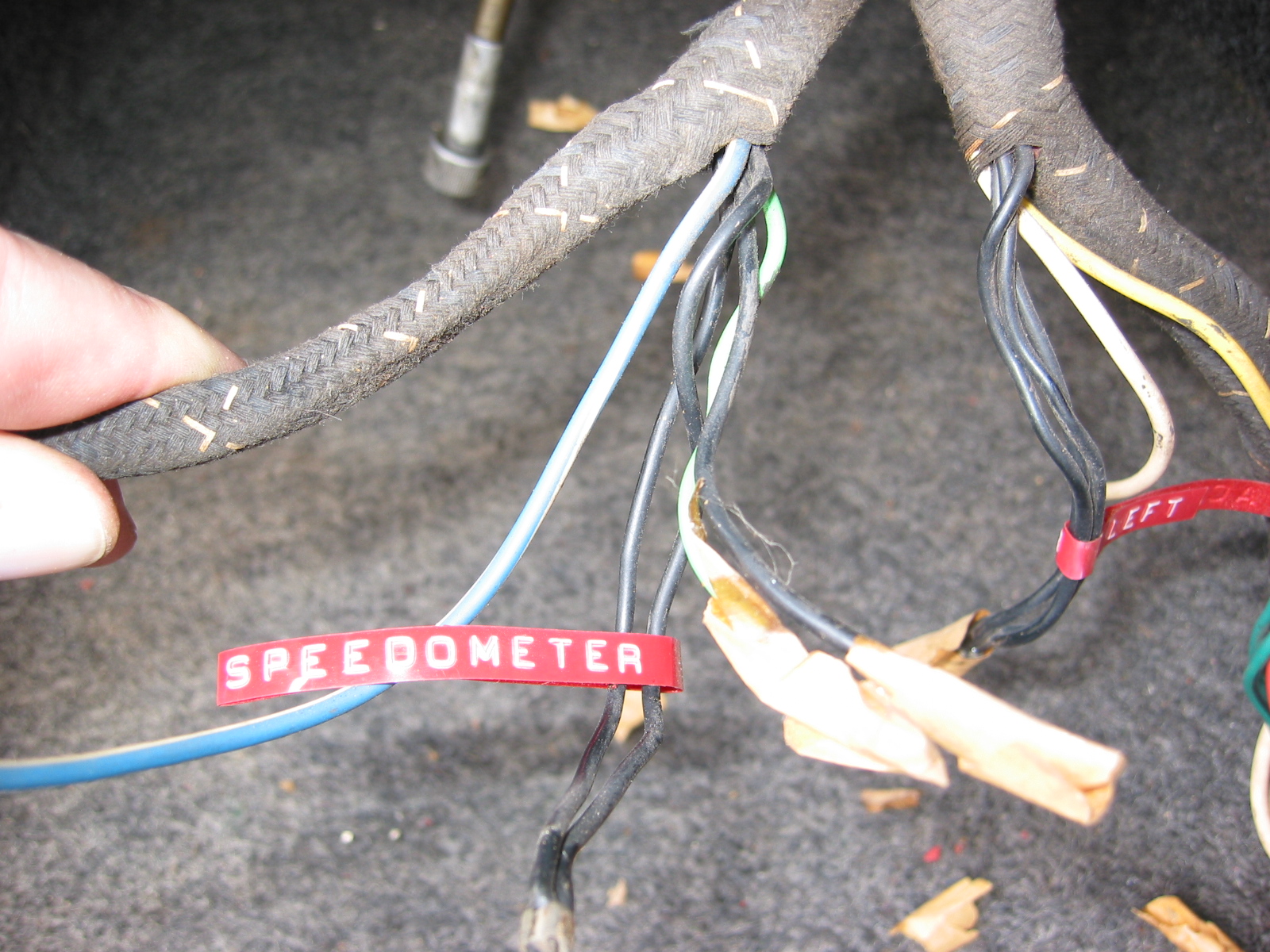
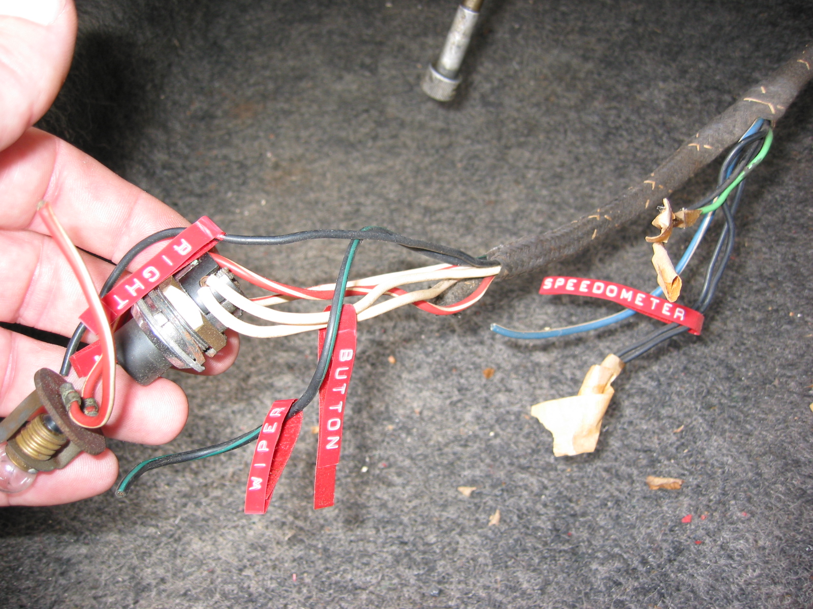
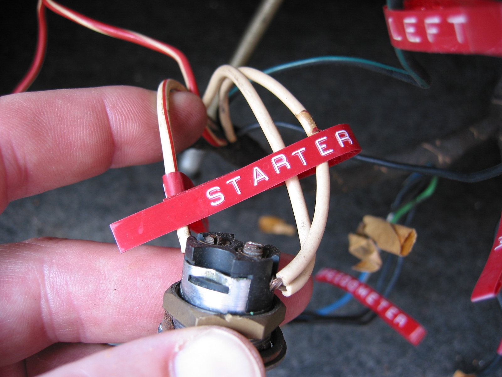
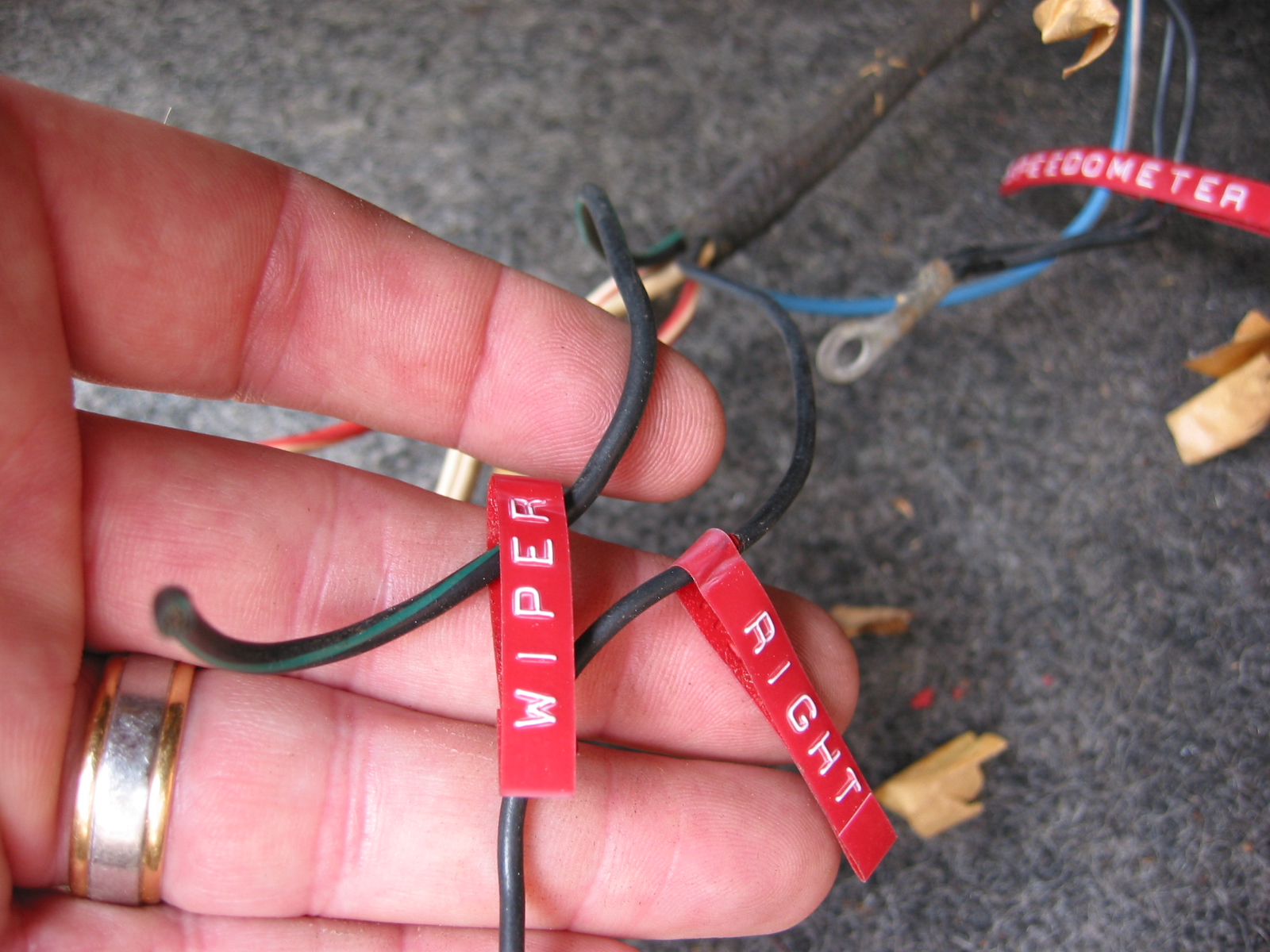
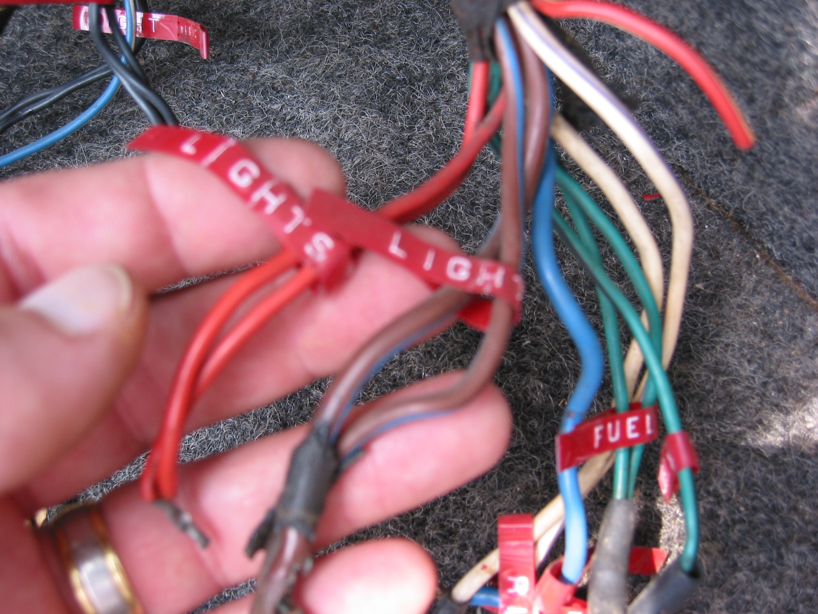
Wiring Harness Trace Patterns
Main Harness – Black with yellow tracers in criss-cross
Chassis Harness – Black with yellow tracer
Rear Harness – Black
Overdrive Harness – Black with yellow tracer
Fuse Box
Lucas Type SF6 Top fuse was a 50 amp – horn circuit. Bottom fuse was a 35 amp fuse. 10 amp used on the in-line number plate lamp circuit.
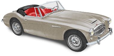
Metallic Golden Beige
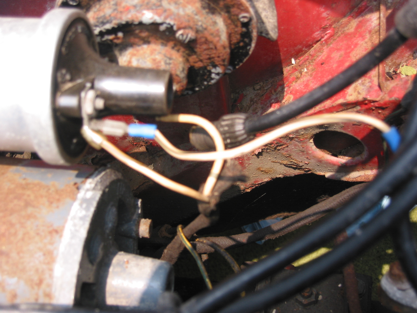
Horns
Lucas type HF1748. On MK IIs the horns were were black Lucas type 9H. One horn produced a high note, the other a low note.
Heater, Air Ducts, and Controls
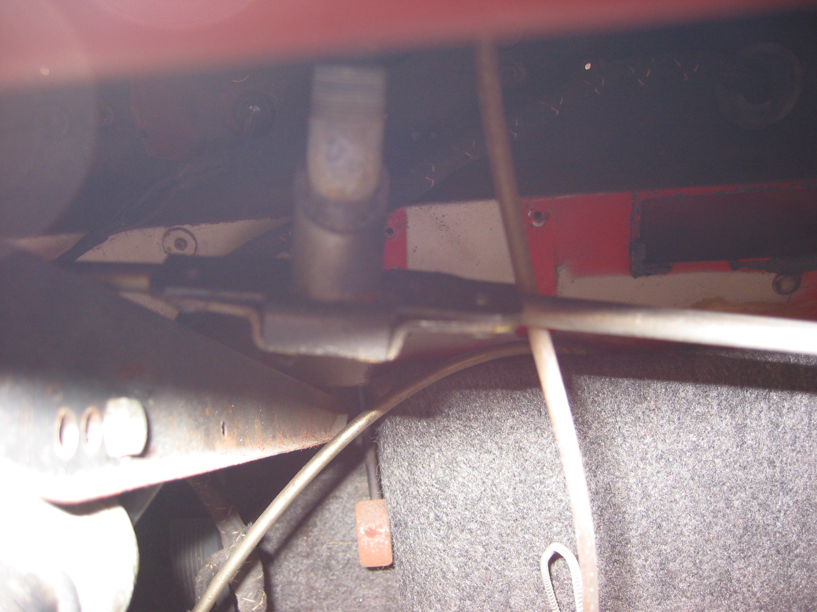
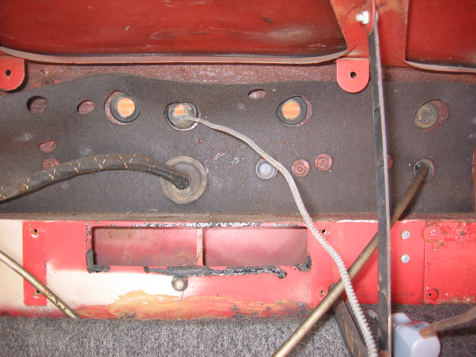
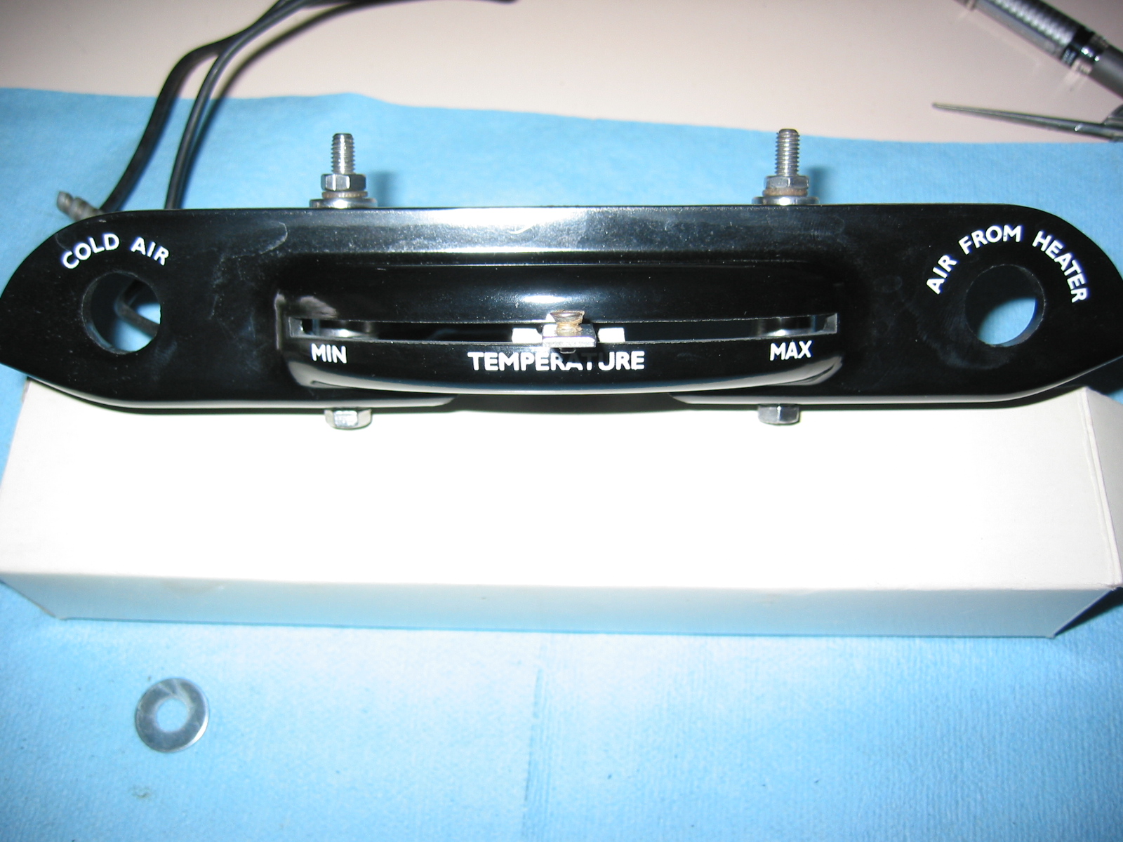
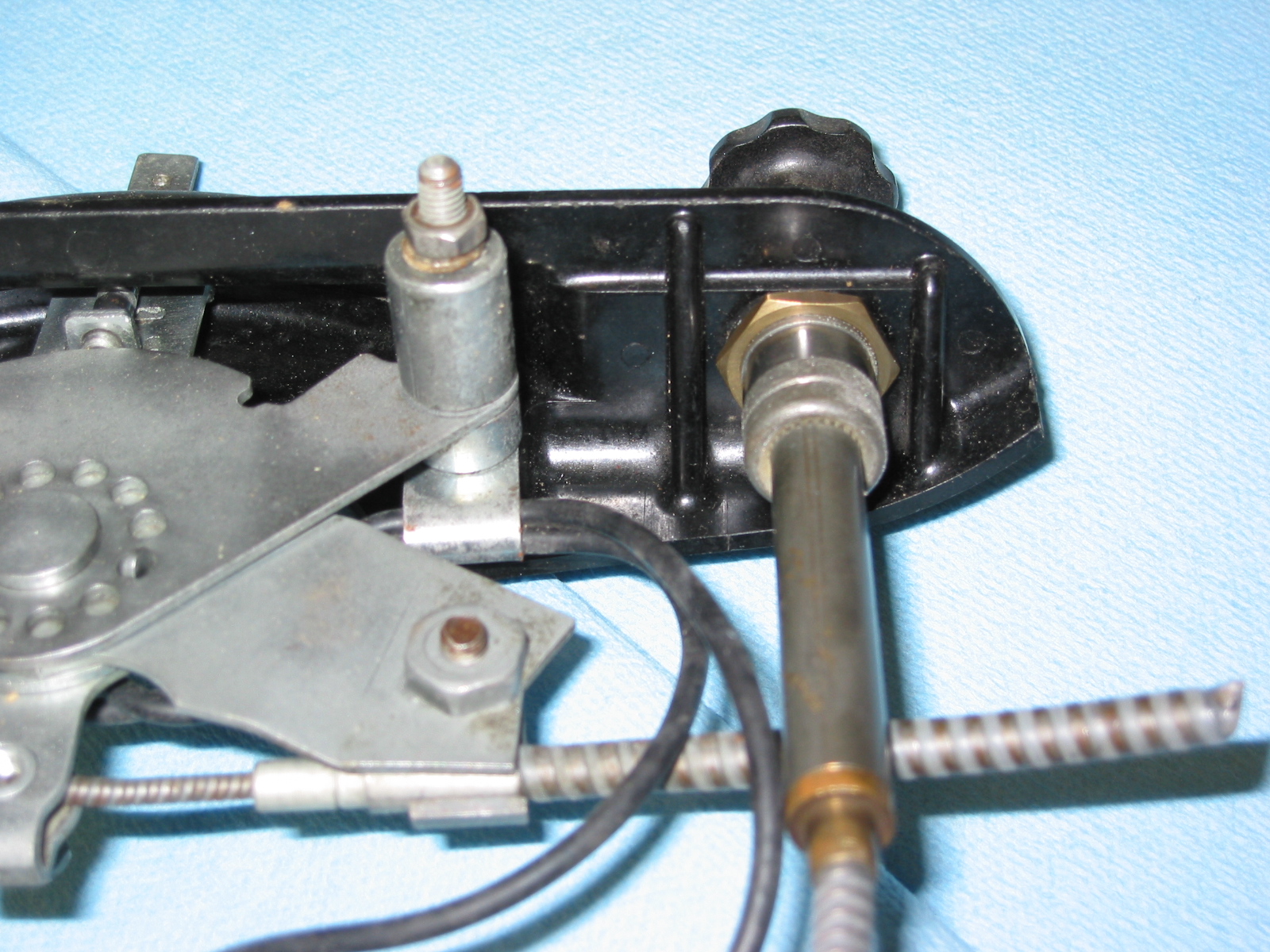
The heater blower was installed after the car was painted as the screws and washers were not painted. The “squirrel cage” was plastic and was unpainted. The hose was mounted to the fender well with a large band clamp. The central sliding control regulated the amount of hot water admitted and thus the temperature. If the knob at the end of the control was pulled the blower would be switched on. The knob on the right regulated the volume of air from the heater, and had to be fully out to shut it off altogether. To obtain the full demisting effect, it was necessary to close the shutters for the heater outlets in the footwells. The left hand pull knob controlled the cold air intake.
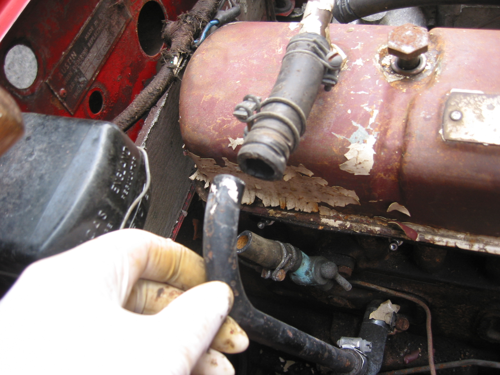
Radiator
Radiator cap was zinc-plated with large domed central brass rivet. 7 lbs. Wire style clamps used universally on hoses.
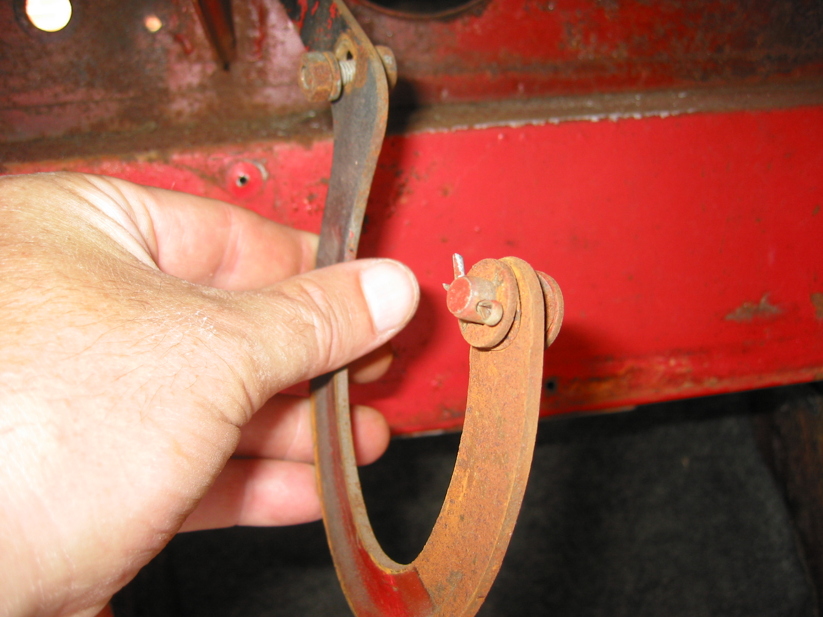
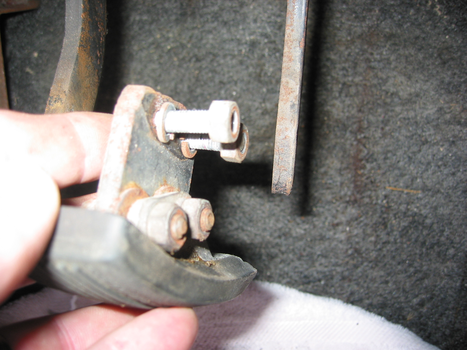
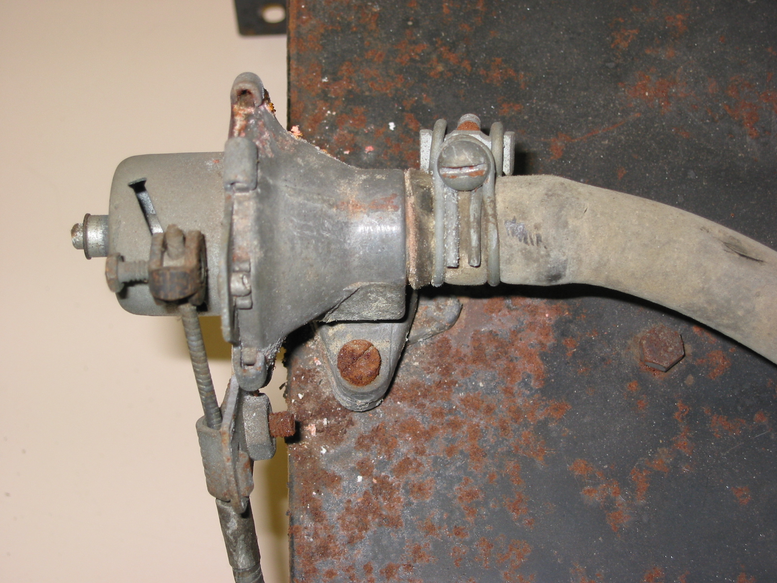
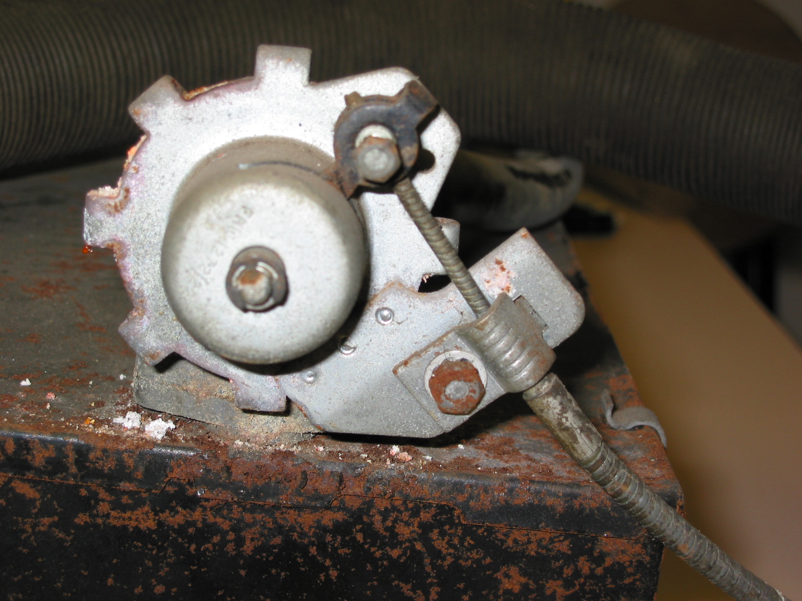
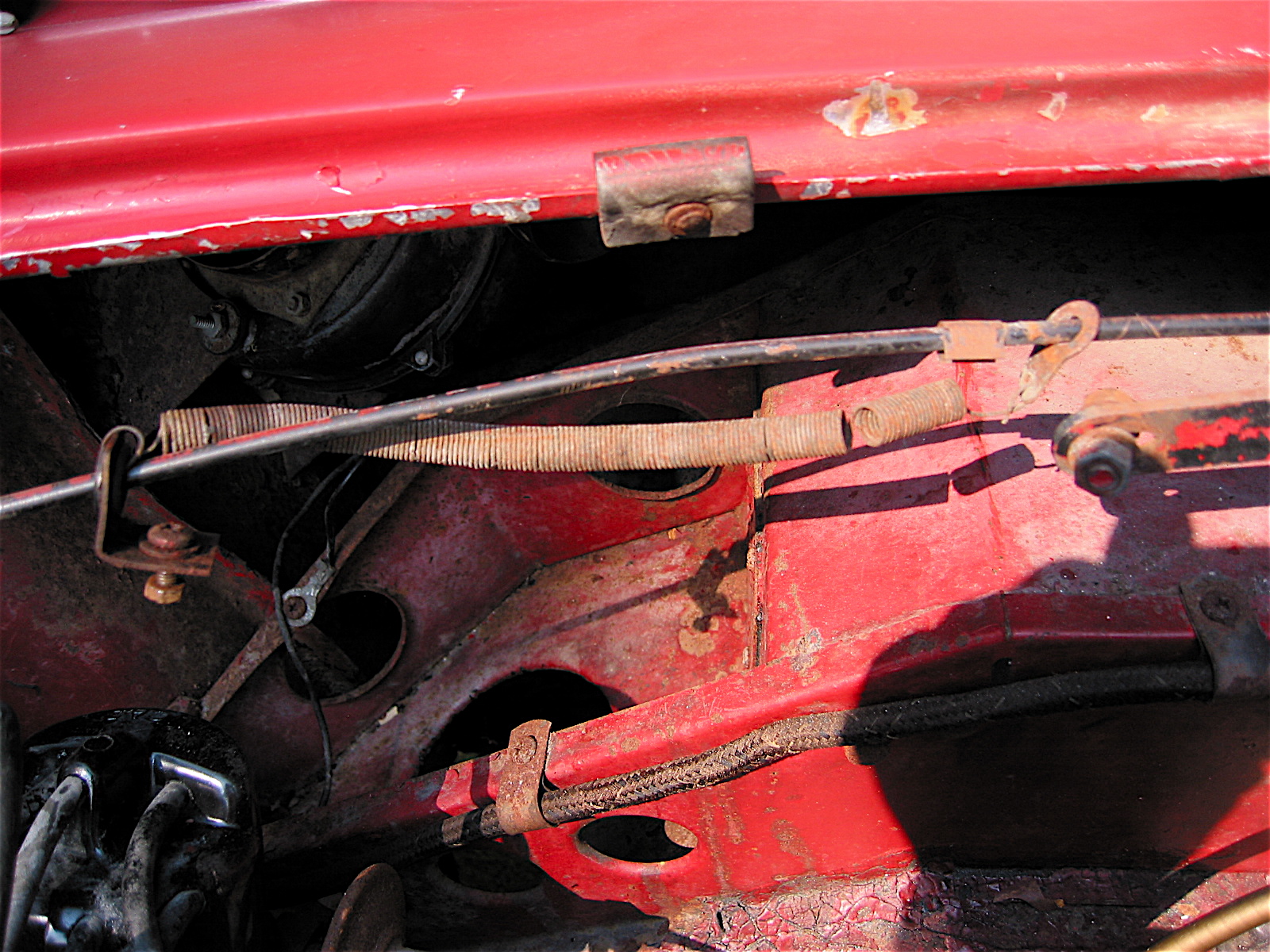
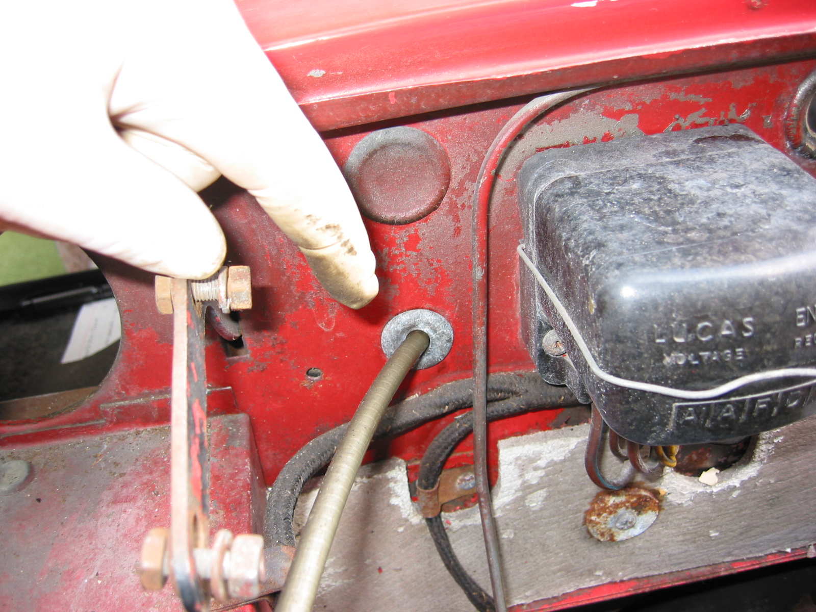
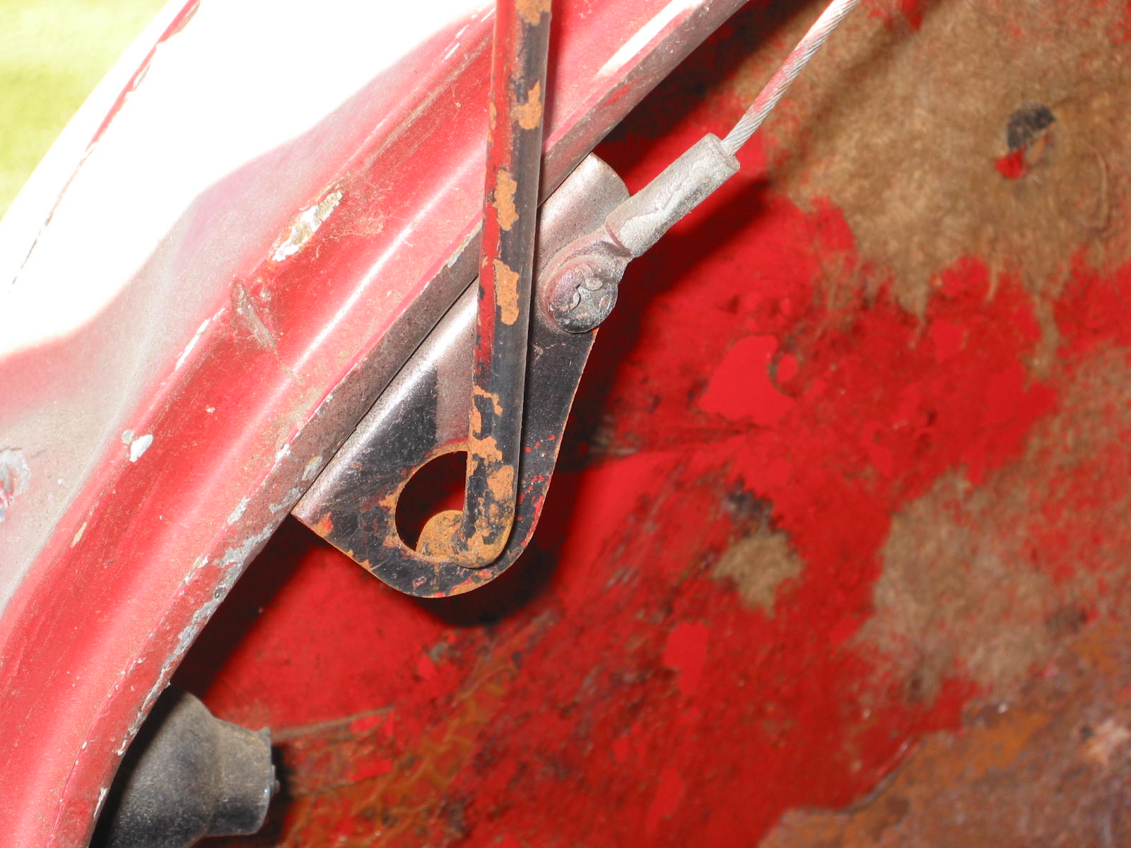
Hood and Attachments
Rubber buffers were held in place with copper plated split rivets inserted from the inboard side. Hood bolt heads were inboard with nuts outboard. Return spring was covered by a thin walled rubber tube.
Paint Combinations
The color combinations from the factory have been included in the foregoing narrative.