British Car Shows
This page includes a chronological photo journal of the various British Car shows I have attended. Car shows proved to be a great place to pick up modification ideas and meeting other Healey people was by far the best part.
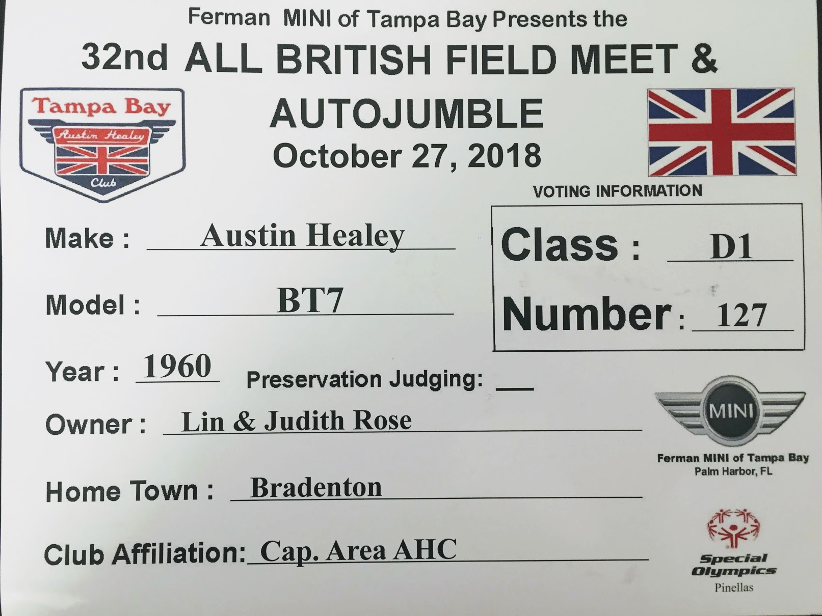
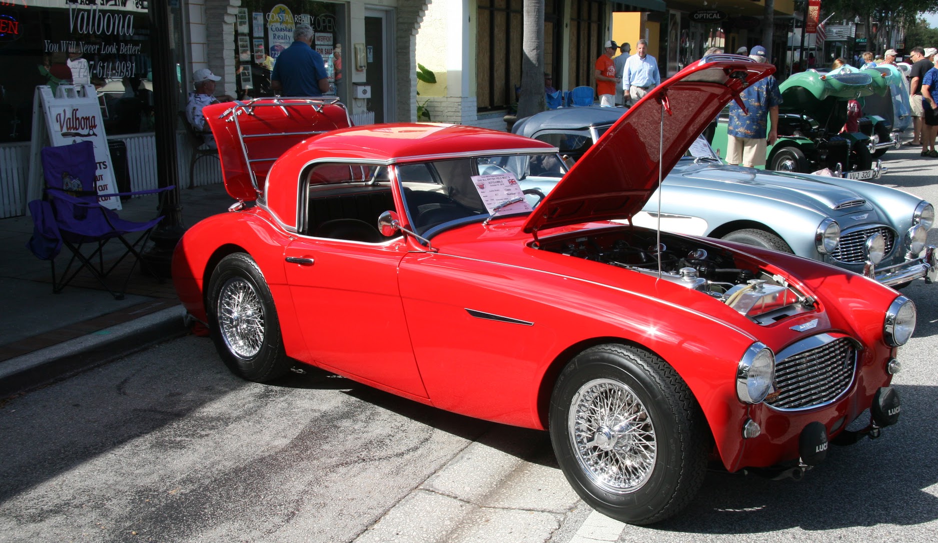
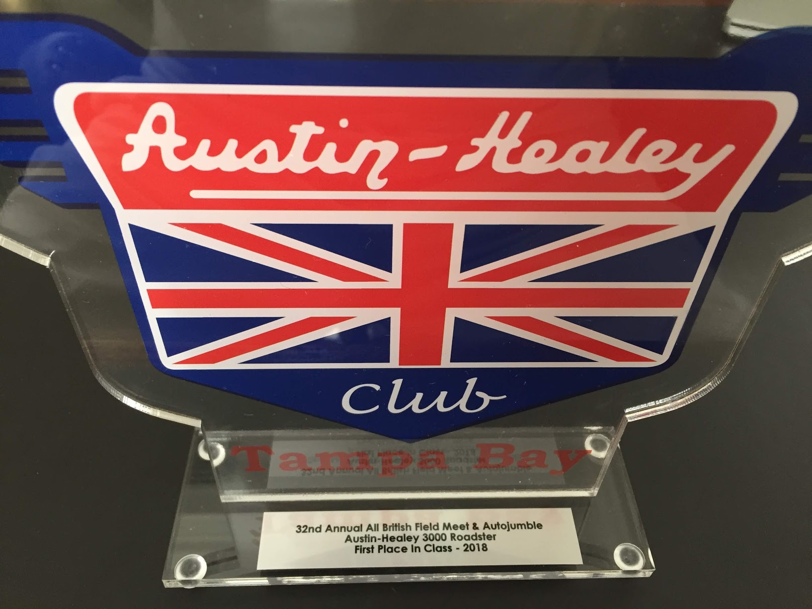
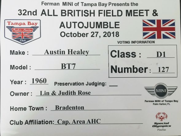
2018 All British Field Meet & Auto-jumble
The Tampa Bay Austin Healey Club hosts this event each year. The show was held in Safety Harbor, FL a quaint “older” Florida community and it was a lovely setting for the show. Safety Harbor is about one hour from Bradenton. Unlike many shows held in a grass field, the community closes a section of Main Street to park approximately 200 registered vehicles.
Registration
It turned out to be a beautiful day with overcast skies and the temperature in the low eighties. The following link will take you to a collection of photos from the show. “The Bloody Beast” received a “First Place in Class.”
https://flic.kr/s/aHsmsDAwtD
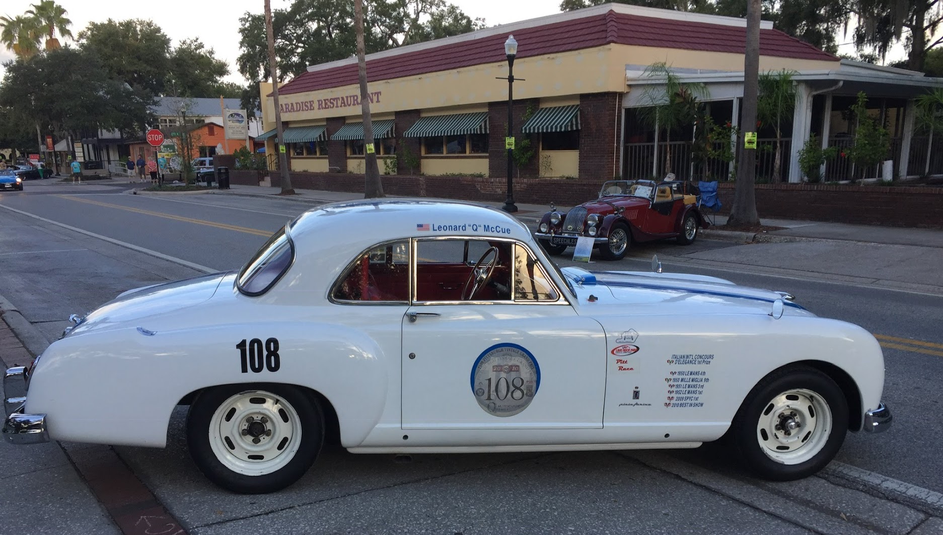
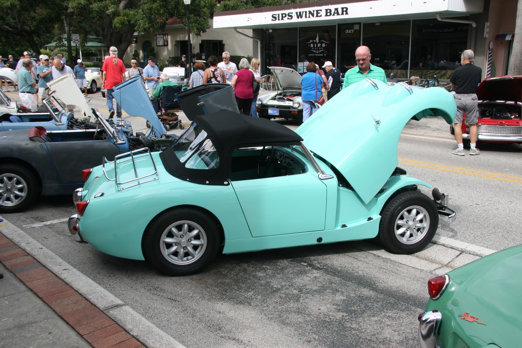
My two favorites:
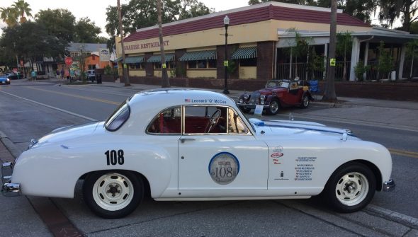
Le Mans Nash Healey

Gorgeous Bugeye
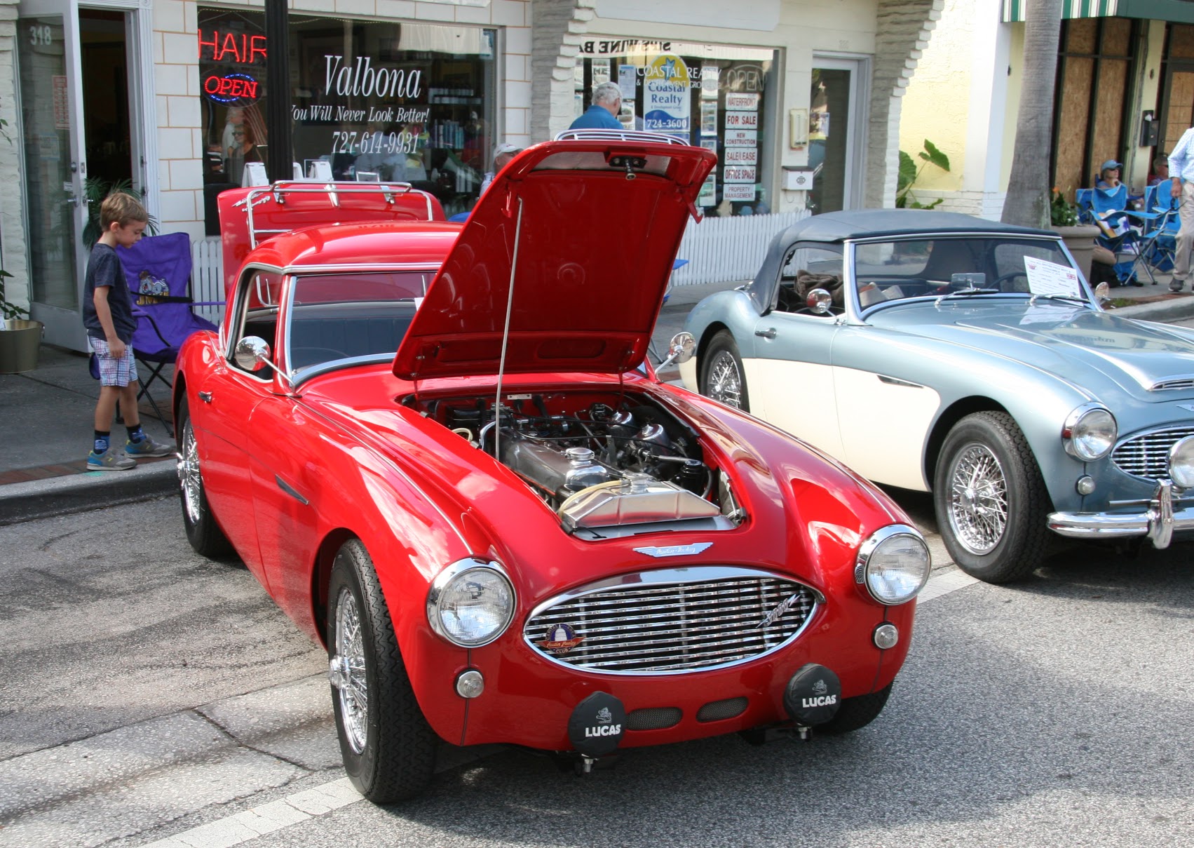
And the Bloody Beast in show:

The Bloody Beast – 1960 AH BT7

The Bloody Beast – 1960 AH BT7

First in Class
2014 Shenandoah Valley British Car Club Annual Show
The SVBCC sponsors a Fall show each year. We have typically not been able to attend due to a calendar conflict, but this year were able to go and as special treat our friends, Steve and Carolyn Thomton from Colorado joined us. It was a beautiful fall day and the Club put on a well attended program. The following link will take you to the photo album for the show. We got a “First in Class,” but it wasn’t much to brag about since there was a grand total of three cars in the Healey side-curtain class!
https://www.flickr.com/photos/valve-chatter/sets/72157648396519171/
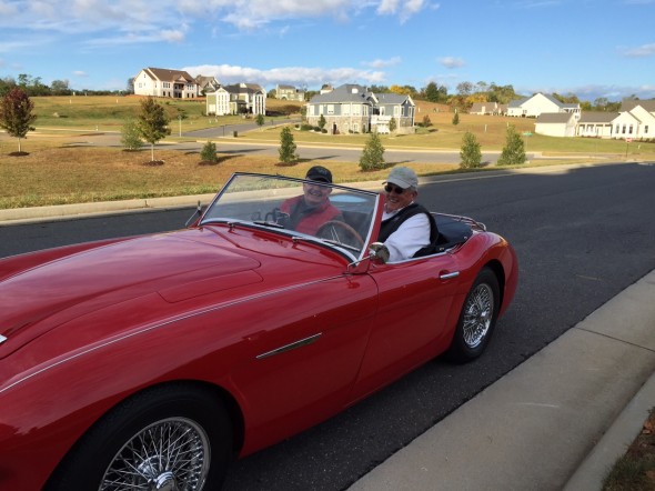
Steve and Lin off to the SVBCC Show
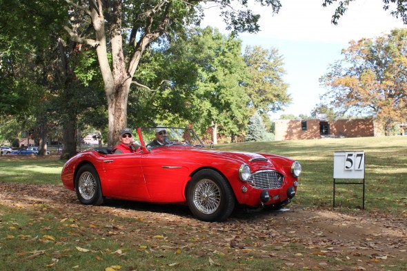
Class “K” #57 1st Place
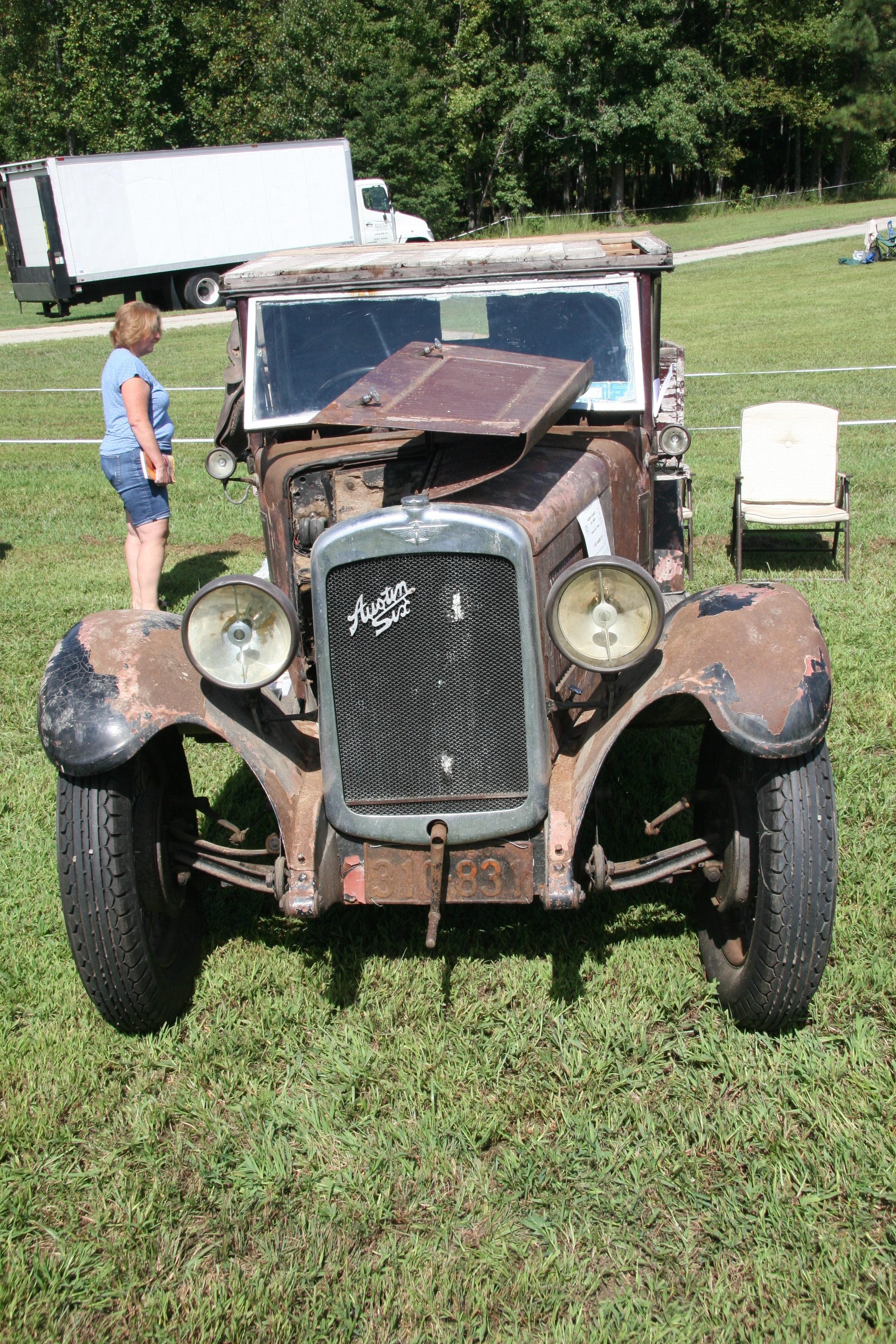
Classics on the Green 2014 New Kent, VA
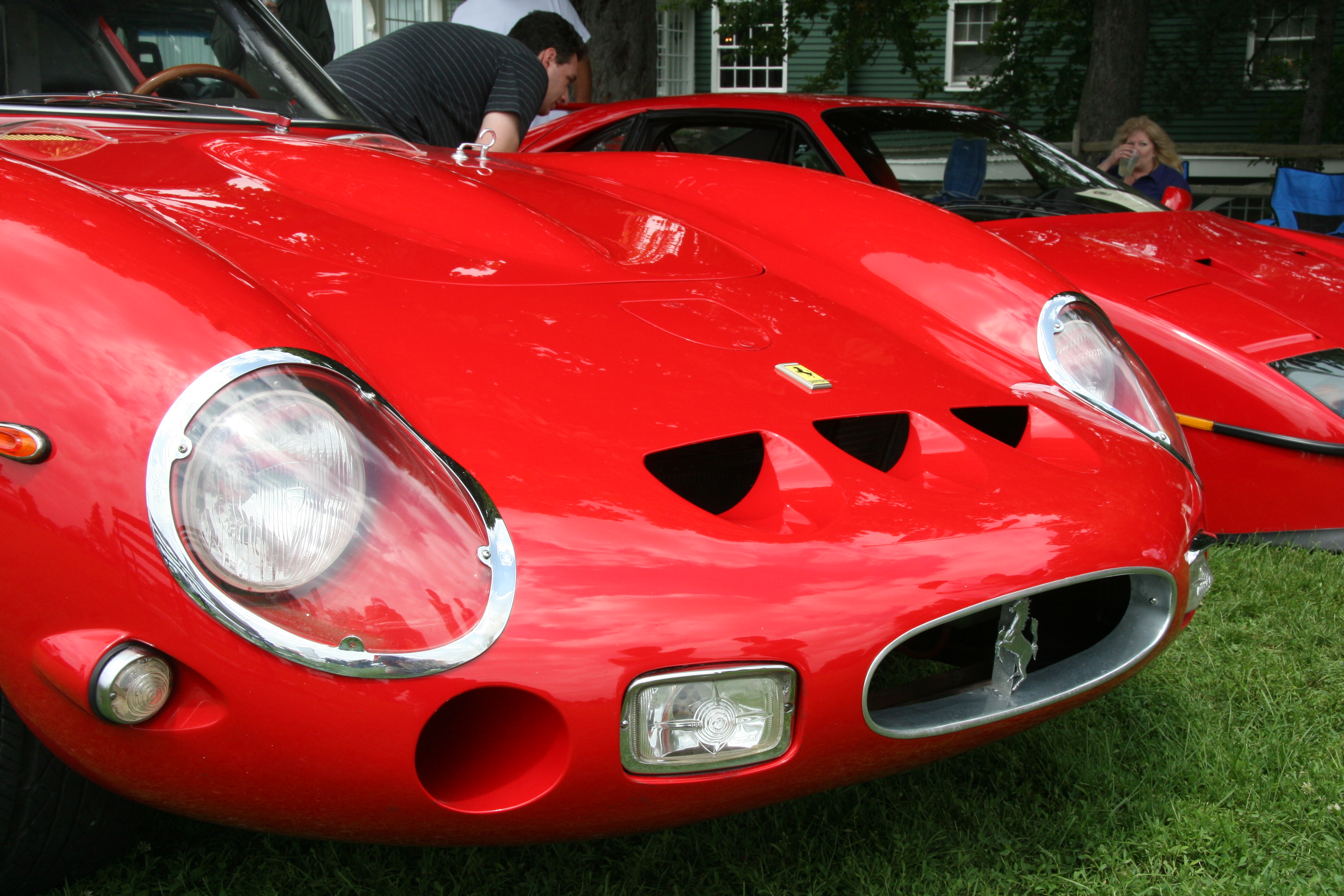
This event is sponsored by the Central Virginia British Car Club. It usually draws around 300 cars. This year the featured marque was Ferrari and I would estimate that there were approximately forty in attendance including a rare Ferrari motorcycle! This is the link to the images of the show: https://www.flickr.com/photos/valve-chatter/sets/72157647193988450/

1930 Austin Six Truck
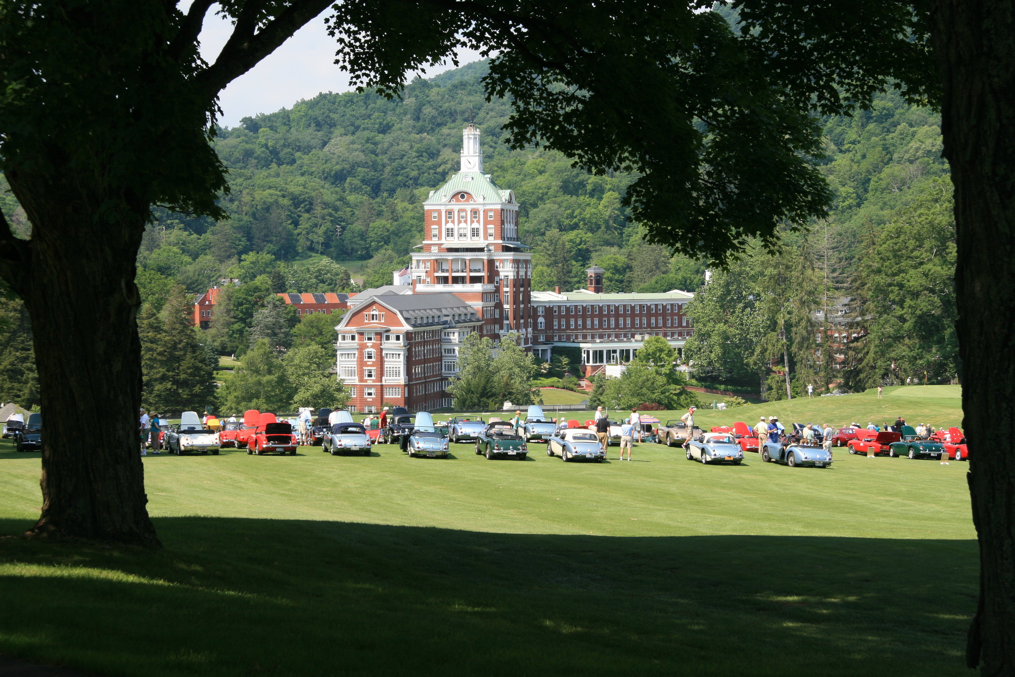
Austin-Healey Conclave 2014
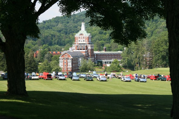
The Homestead Conclave 2014
My wife, Judith, and I attended the annual Conclave held at the stately Homestead Resort in Hot Springs, Virginia. The Conclave began on Sunday, June 15 and concluded on Thursday evening, June 19. The car show was held at a gorgeous venue (the golf practice range) on an equally beautiful crystal clear day. This is a link to the images taken at the show:
https://www.flickr.com/photos/valve-chatter/sets/72157645200978751/
Pittsburgh Vintage Gran Prix 2013

Ferrari 330 Star of the Show
My son, Scott, and I attended the show and races this year. This is always a great weekend. I had not attended in nine years, but the events were better than ever. This is a link to the photos I took at the show and races: http://flic.kr/s/aHsjH3J9vo
Monterey, CA Auctions 2012
Pebble Beach Concours d Elegance, 2012

I was able to attend the Gooding and RM auctions in August, 2012 at Monterey and Pebble Beach, CA. It was definitely a “bucket list” item! What beautiful and often quite rare automobiles. The following link will direct you to a collection of three sets or albums of images from these two auctions as well as some cars sold at the Mecum auction that happened to be located at the Hyatt where I was staying:
http://www.flickr.com/photos/valve-chatter/collections/72157631256039158/
I was also able to attend the Concours d Elegance at the Pebble Beach Lodge and Golf Course. What an amazing show. Claimed by many to be the best car show in the world. This is a link to the Concours images:
http://www.flickr.com/photos/valve-chatter/sets/72157631255282230/
Classics On The Green 2011
Sponsored by the Central Virginia British Car Club  The Central Virginia British Car Club held its annual car show at the New Kent Winery in New Kent, Virginia. Scott Rose and I took “The Bloody Beast” to the show which had as a featured marque the cars of Donald Healey. A special display of each model type of Healey’s cars was assembled by Jim Cox for the spectators. In reality, the show is open to all european makes, which made for a very interesting show. It was nice to look at the old and the new – Bentleys and Ferraris! This was a very well organized event that I will definitely plan to attend again in 2012. Click on the icon to the left to view a collection of photos from the event. Click the link below to view an album of the event. http://www.flickr.com/photos/valve-chatter/sets/72157630738687508/
The Hunt Country Classic 2011
Sponsored by the Washington DC MG Car Club  Members of The Capital Area Austin Healey Club attended the 2011 edition of the Hunt Country Classic in near record numbers. The weather was perfect, approaching 80 degrees in the afternoon with clear skies. The event is held at Willoughby Farm, home of the host, Barbara Scott. The farm is nestled midway between historic Marshall, and lovely Middleburg, deep in the rolling hills of Virginia’s incomparable Hunt Country. “The Bloody Beast” took second in class again this year with Tim Flaherty taking first with his Old English White AH 100. Club members did very well with a number of trophies taken home by the Club. Click on the icon to the left to link to photos taken at the show.
Click the link below to view an album of the event.
Encounter 2011
The Austin Healey Sport and Touring Club  The Austin-Healey Sports and Touring Club – A Car Club for Healey, Austin-Healey, and Austin-Healey Sprite Owners and Enthusiasts with regions in New York, Pennsylvania, Delaware and New Jersey always puts on a great annual event referred to as “Encounter.” The event is held in August of each year. A judged Concours, popular vote car show, a rallye, tech sessions, a gymkhana, funkhana, valve cover races and a flea market are just a few of the usual events. Click the image to the left to view a slide show of the 2011 event held in Paradise, PA. My son Scott and I attended this year. We were only able to attend the popular car show on Saturday, so we didn’t drive the Bloody Beast or the Bugeye this time, as it is a four hour, fifteen minute trip each way. We had a great time, nonetheless. Click the link below to view an album of the event. http://www.flickr.com/photos/valve-chatter/sets/72157630737393610/
British Invade Gettysburg 2011
Sponsored by the Lanco MG Club  Since 2000 the Lanco MG Club has sponsored this “all marques” British Car show at the Outlet Mall in Gettysburg, PA. The event is pretty loosely organized, as cars are not arranged by marque and they are not judged. It is simply an occasion for the general public and fellow car owners to enjoy viewing a couple hundred beautiful automobiles. As one would expect on July 17, it was a warm Sunday afternoon, but it was a clear and beautiful day. A number of CAAHC members were on hand. Click the link below to view an album of the event. http://www.flickr.com/photos/valve-chatter/sets/72157630737075302/
The Hunt Country Classic 2010
Sponsored by the Washington DC MG Car Club  Members of The Capital Area Austin Healey Club attended the 2009 Hunt Country Classic in Marshall, Virginia on October 10. The event is held at Willoughby Farm, home of the host, Barbara Scott. The farm is nestled midway between historic Marshall, and lovely Middleburg, deep in the rolling hills of Virginia’s incomparable Hunt Country. The weather was unbelievably beautiful for this outing. Almost eighty with a crystal clear blue sky. “The Bloody Beast” finished second in class this year, with Mac Holt taking first place with his silver over black 1957 100-6. Mac also won the Mayor’s trophy with Jack White winning the Ambassador’s trophy! It was a great day for the CAAHC! Click the link below to view an album of the event. http://www.flickr.com/photos/valve-chatter/sets/72157630736908560/
The Original British Car Day 2010
Sponsored by the Chesapeake Chapter of the New England MGT Register  Members of The Capital Area Austin Healey Club attended the 2010 Original British Car Day at Lilypons Water Gardens in Adamstown, MD on June 6, 2010. There is always a great turn out of British cars at this event with healthy collection of Austin Healeys. Unfortunately, the Show tends to be plagued with the sudden arrival of thunderstorms and this year was no different. Many people left at about 1:00 pm before the storm actually hit. The Land Rover was the official marque of the show this year as it celebrated 60 years since first rolling off the production line. “The Bloody Beast” was an award recipient at the the OBCD winning first place among the Big Healeys and we collected a nice pewter plate for our efforts. However, as always, it was really the opportunity to visit with other car owners and with young people interested in learning more about British cars that made the event fun. Click the link below to view an album of the event. http://www.flickr.com/photos/valve-chatter/sets/72157630736619516/
The Hunt Country Classic 2009
Sponsored by the Washington DC MG Car Club  Members of The Capital Area Austin Healey Club attended the 2009 Hunt Country Classic in Marshall, Virginia on October 11. The event is held at Willoughby Farm, home of the hosts, Bill and Barbara Scott. Their farm is nestled midway between historic Marshall, and lovely Middleburg, deep in the rolling hills of Virginia’s incomparable Hunt Country. The weather was unbelievably beautiful for this outing. Mid-seventies with a crystal clear blue sky. The “Bloody Beast” wasn’t able to park with the other Healey’s this year! Having won first place in 2008, my car was not eligible to compete for a prize. So, I was parked with other first place cars from last year in the Prince of Wales category. Judith Rose was the proud recipient of the third place award for her sweet potato cake! Click the link below to view an album of the event. http://www.flickr.com/photos/valve-chatter/sets/72157630736424410/
The Scottish Games 2009
The Capital Area Austin Healey Club  Members of The Capital Area Austin Healey Club attended the 2009 version of the Scottish Games held at Great Meadows, Virginia on September 9. A car show for British makes is held in conjunction with the Games although it is certainly secondary to the Games “competitions” and vendor displays. Wool tartan products, family clans, and Scottish foods are available to all attending. Click the link below to view an album of the event. http://www.flickr.com/photos/valve-chatter/sets/72157630736301500/
James Madison University
Homecoming Parade 2008  Judith and I have ridden in the annual JMU Homecoming Parade for the last 11 years. However, we have always been passengers in someone else’s convertible. This year, we drove ourselves in the “Bloody Beast.” We may have had more fun than the spectators! Click on the link below to see a few Homecoming Parade photos. http://www.flickr.com/photos/valve-chatter/sets/72157630736183240/
The Hunt Country Classic 2008
Sponsored by the Washington DC MG Car Club  Members of The Capital Area Austin Healey Club attended the 2008 Hunt Country Classic in Marshall, Virginia on October 12. The event is held at Willoughby Farm, home of the hosts, Bill and Barbara Scott. Their farm is nestled midway between historic Marshall, and lovely Middleburg, deep in the rolling hills of Virginia’s incomparable Hunt Country. The weather was unbelievably beautiful for this outing. Mid-seventies with a crystal clear blue sky. At last count there were twenty-four Healeys in attendance, with several hundred representatives of other British marques. Thanks to Mary Oritt for encouraging attendance and organizing a “dessert competition.” Judith Rose was the proud recipient of the first place award for he COSTCO cupcakes! This is a show for pleasure, and the company of others who share interest in vintage British machinery. In this vein, judging is by popular vote of one’s peers, each of whom has a car entered in the show. Each entrant receives one ballot, and may cast one vote per class. The Healeys were divided into two classes: side curtain and roll-up window. “The Bloody Beast” took home 1st place in the side curtain class. Click the link below to view an album of the event. http://www.flickr.com/photos/valve-chatter/sets/72157630736015438/
The Scottish Games 2008
The Capital Area Austin Healey Club  Members of The Capital Area Austin Healey Club attended the 2008 version of the Scottish Games held in Delaplane, Virginia on September 14. A car show for British makes is held in conjunction with the Games although it is certainly secondary to the Games “competitions” and vendor displays. Wool tartan products, family clans, and Scottish foods are available to all attending. This year the event was exceptionally warm. The temperature was in the mid-nineties with humidity about the same. Still, it is always fun to get the Club together and everyone had a good time. Click the link below to view an album of the event. http://www.flickr.com/photos/valve-chatter/sets/72157630735760916/
Encounter 2008
The Austin Healey Sport and Touring Club  The Austin-Healey Sports and Touring Club – A Car Club for Healey, Austin-Healey, and Austin-Healey Sprite Owners and Enthusiasts with regions in New York, Pennsylvania, Delaware and New Jersey always puts on a great annual event referred to as “Encounter.” The event is held in August of each year. A judged Concours, popular vote car show, a rallye, tech sessions, a gymkhana, funkhana, valve cover races and a flea market are just a few of the usual events. Click the link below to view an album of the event held in Carlisle, PA. My son John and I attended this year. John drove the Bugeye and I drove the “Bloody Beast” from Harrisonburg.We enjoyed the best weather I can ever remember for an Encounter. We were only able to attend Friday and Saturday, but had a wonderful time. John did some outstanding gymkhana driving and the “Bloody Beast” took home first place in the MK I category. http://www.flickr.com/photos/valve-chatter/sets/72157630735572622/
The Capital Classic 2008
The Capital Area Austin Healey Club  The Capital Area Austin Healey Club – A Car Club for Healey, Austin-Healey, and Austin-Healey Sprite Owners and Enthusiasts within the DC region puts on an annual event referred to as “The Capital Classic.” The event is held in June of each year and is typically attended by 30+ enthusiasts. The format varies and has included a popular vote car show, a rallye, tech sessions, and a funkhana. The 2008 “Classic” was held in beautiful Cumberland, Maryland. This year the focus was on Healey fellowship, driving our cars, and appreciating the landscapes. The program included an historian’s lecture on the area, a walking tour of downtown Cumberland with its historic architecture, a steam locomotive ride to Frostburg, MD, and a wonderful scenic drive on Sunday. All club members are indebted to Mary and Michael Oritt for planning and executing the event. Click the link below to view an album of the event. Click the link below to view an album of the event. http://www.flickr.com/photos/valve-chatter/sets/72157630734563432/
Encounter 2005
The Austin Healey Sport and Touring Club  The Austin-Healey Sports and Touring Club – A Car Club for Healey, Austin-Healey, and Austin-Healey Sprite Owners and Enthusiasts with regions in New York, Pennsylvania, Delaware and New Jersey always puts on a great annual event referred to as “Encounter.” The event is held in August of each year and is typically attended by 200+ enthusiasts. A judged concours , popular vote car show, a rallye, tech sessions, a gymkhana and a flea market are just a few of the usual events. Click the link below to view an album of the event. http://www.flickr.com/photos/valve-chatter/sets/72157630734251084/
Conclave 2005
The Triad Austin Healey Club of America The Triad Club of the AHCA hosted the 2005 Conclave in Winston-Salem, NC. the last week of June. The Conclave is typically about a week long affair with concourse judging, a rally, tech sessions, a funkhana, a gymkhana, and a popular car show among other events. Click the link below to view an album of the event. https://www.flickr.com/photos/valve-chatter/sets/72157630733926720/