Chapter 61 Week Thirty-One July 16, 2007

Waiting. Still waiting.

Jack Harper from Coach Works called on Wednesday, July 18 to say that he finally had the block from the machine shop!! This is a red-letter day. Jack indicated that he will start assembly on Monday. I will take all the bits-n-pieces to him so that he is ready to start work.

The block work was done by Dale Engineering. The block was cleaned, the main bearings were align bored, the crank was magnafluxed and turned, brass plugs and core plugs were replaced, cam bearings were installed and everything was balanced.

Chapter 59 Week Twenty-Nine 7/2/2007

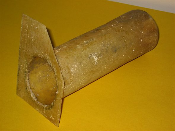
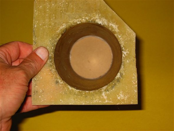
I am waiting on the completion of the engine rebuild and I recalled that Tracy Drummond had fabricated a little stowage bin to fit into the frame lightening hole on the right firewall support. He made his from fiberglass and used a tobacco can as the mold.

I decided to try my hand at it, but opted to use a longer can as the form, and one that had contents more pleasant for me to consume than tobacco. Yes, I used one of those nice Glenfidditch Scotch boxes for my little project!  Images to the right illustrate the various stages of the creation of the storage “stow-it.” Thanks to Tracy Drummond for the idea! It will be painted red to match the car.

Stow-it Tube 2

Stow-it Tube 1

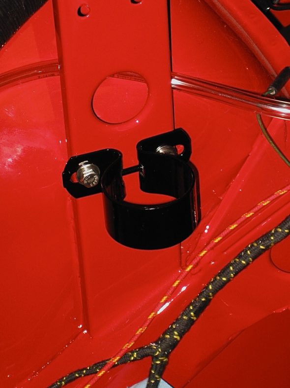
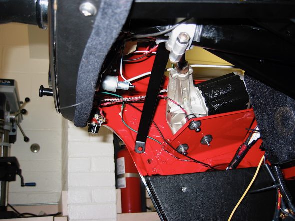
I realized today that I had not made provisions for mounting the coil in the engine bay since I am switching from dynamo to alternator. I drilled two holes in the bonnet support upright and installed nutserts to make it easy to secure the coil bracket and not have to fool with nuts in tight places.

Coil Bracket

Chapter 57 Restoration Assembly, Week Twenty-Seven 6/18/2007

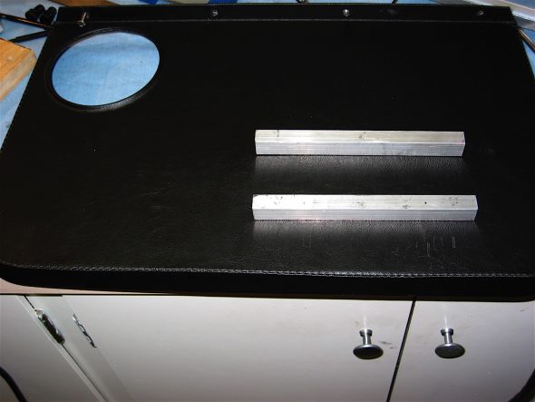
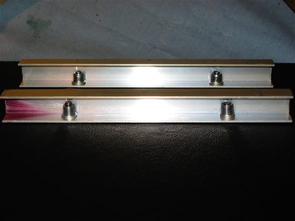
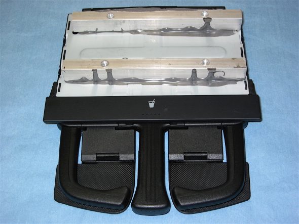
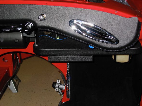
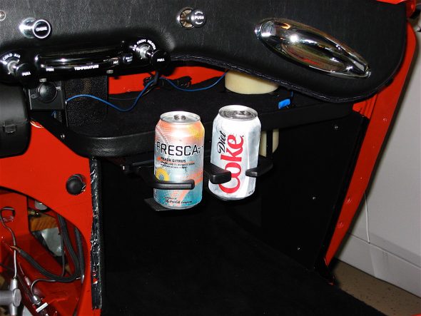
Roger, aka AUSMHLY, on the British Car Forum used a Volkswagon Jetta cup holderon his BJ8. While it doesn’t work quite as well on the BT7 because the parcel tray is mounted below and behind the dash fascia, I bought the same cup tray on eBay and mounted it to the parcel tray. I used some 3/4” aluminum bracket mounted to the tray with #10 nutserts and glued the aluminum brackets to the cup holder with JB Weld. After the initial install, I decided the looks would be improved by covering the little plastic cup holder door with the same vinyl as on the dash fascia. It will work well with 12 ounce cans and small bottles for those long hot road trips. Thanks to Roger for the tip!

Cup holder bracket 1

Cup holder bracket 2

JB Weld Aluminum bracket 3

Vinyl Covered cup holder door 8

Cup holder in Action 6

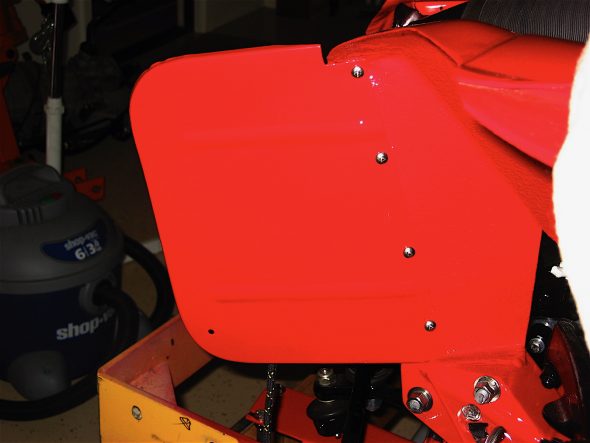
The front splash panels were next on my short list to install. Four #8 SS sheet metal screws were used for each panel.

Splash panel RH

Splash Panel LH

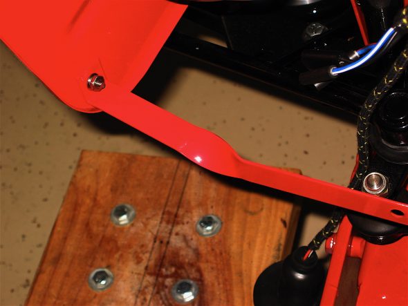
Splash Panel Bracket

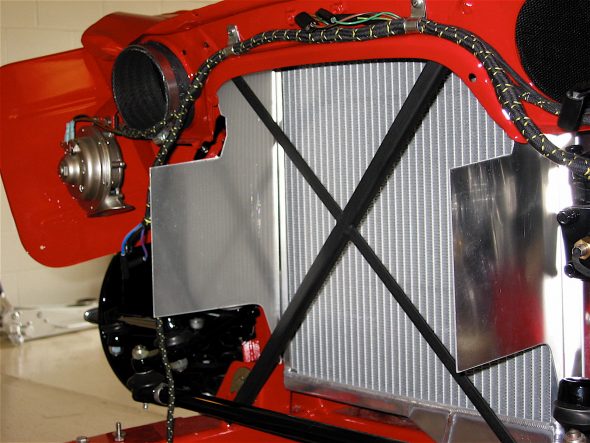
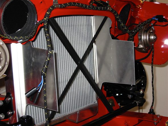
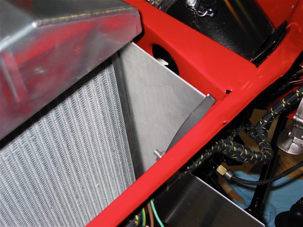
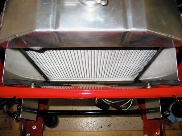
I fabricated a pair of radiator baffles to help funnel air to the radiator. Unlike the original system, these don’t permit air to escape to the sides of the radiator. I had seen the applied idea at Conclave a few years ago on Keith Pennell’s car. He graciously sent cardboard templates to me. I modified them slightly and had a local shop cut them out of aluminum for me.

I installed the Cape International aluminum radiator and the baffles for fit. I will need to pull them out before the engine goes in. When I do pull them, I will bend the “wings” of the baffles outward a bit.

Radiator Baffles 1

Radiator Baffles 2

Radiator Baffles 3

Radiator Baffles 5

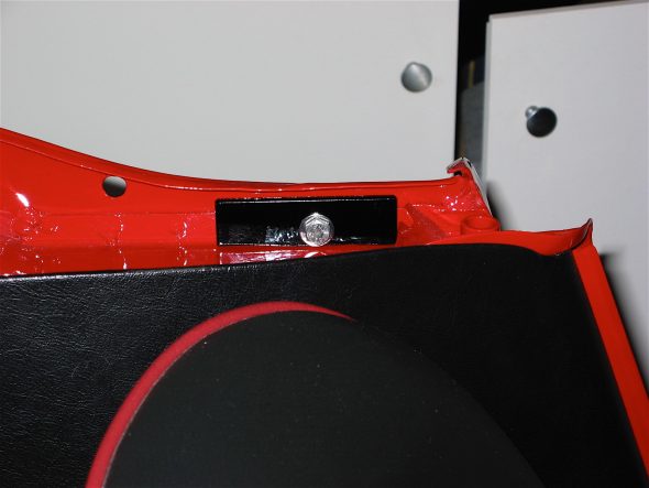
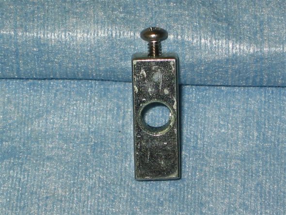
I reviewed all my remaining parts and located three items that I could put in place although they cannot be finally installed until later when I install the body panels and windscreen. The first was the steering column steady bracket and the second was the small tapped steel plate for the mounting of the front of the rear wings.  Finally, the pair of splash panel bracketsthat mount to the grill and shroud were attached.

Steering Column Steady Bracket 2

wing mounting plate

Just so I won’t forget later, I went ahead and greased the grease fittings on the front suspension/steering and the handbrake. Now I am already to go once the work on the engine is complete.

Chapter 56 Restoration Assembly, Week Twenty-Six 6/11/2007

Other than installing the finished motor and the body components I am now down to just a few bits here and there. I am starting to get excited about the finished product after so many months (years actually!) of hard work.

At the factory the two rubber buffers that mount to each of the wheel arch assemblies  were fastened to the assembly before painting the tub, but I installed them after painting to make sure that all surface areas were covered well with paint. Copper split rivets and washers are used to fix each buffer to the wheel arch.
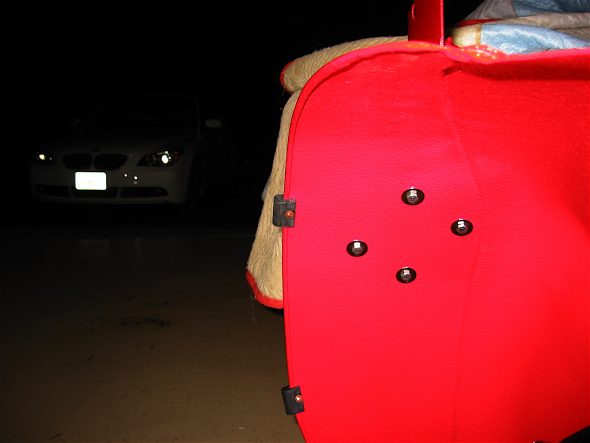
Rubber Buffers
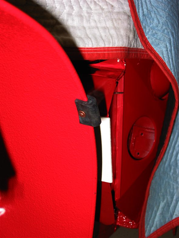
Rubber Buffers 2

The front wing support brackets were added next. I carefully attached them in the same positions they were in for panel fitting.
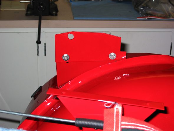
Front Wing Support Bracket LH
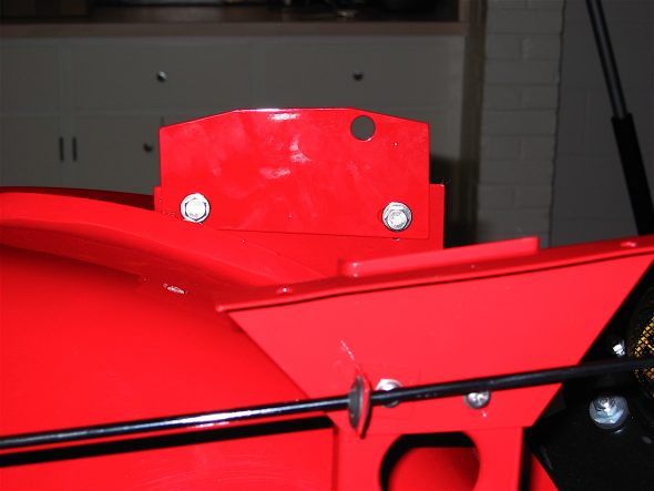
Front Wing Support Bracket RH

The bonnet support plates were added next. These were not fastened tightly so that they might be adjusted easily after the front shroud was installed
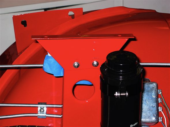
LH Bonnet Opening Support Plate
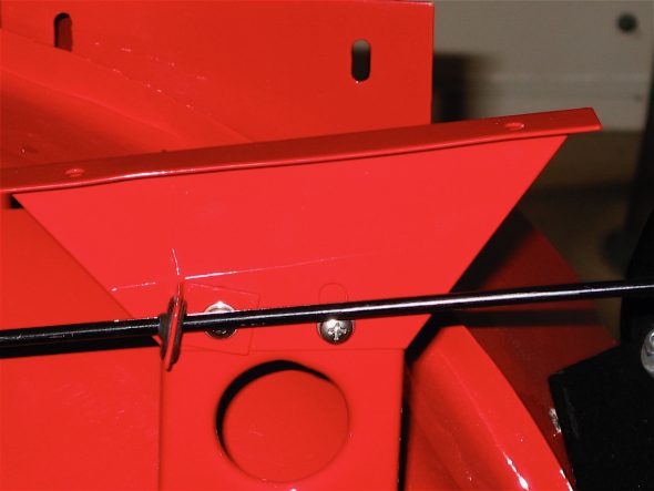
RH Bonnet Opening Support Plate

To avoid losing radiator coolant I decided to add a coolant overflow reservoir tank to the Bloody Beast. I fabricated a bracket to mount it to the superstructure and ran a clear hose parallel to the wiring harness that runs down the RH firewall brace.
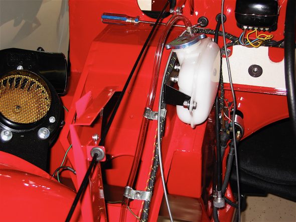
Radiator overflow tank
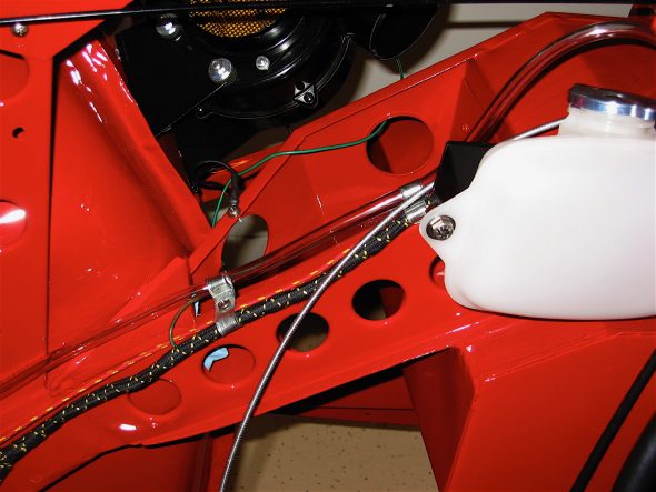
Radiator overflow hose routing

I purchased a stainless steel braided hose for the clutch slave cylinder from Moss Motors. I attached it to the new Lucas slave cylinder and then inserted it into the retainer clip on the frame to screw it into the clutch pipe running up the RH footbox. Doug Reid aka Mr. “Finespanner,” fabricated a short bleeder pipe for me that will mount on the bell housing making it much easier to bleed the clutch in the future.
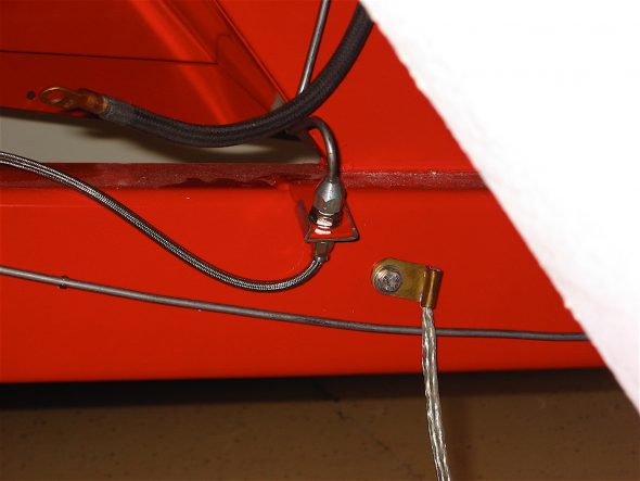
SS Slave cylinder hose
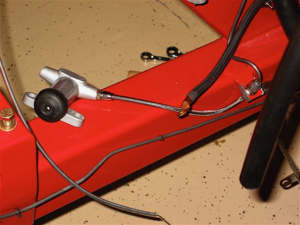
Slave cylinder

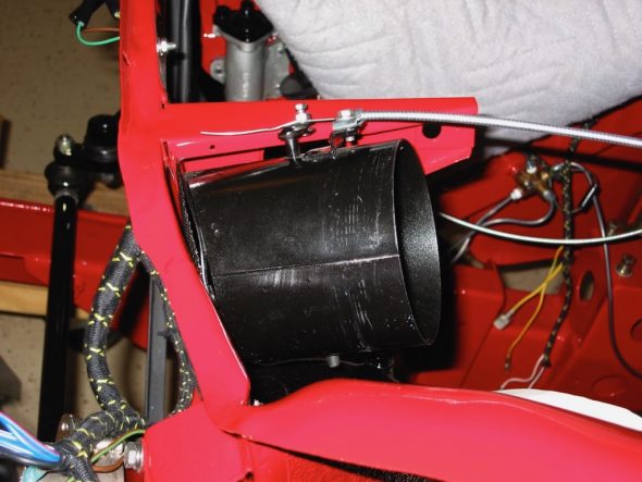
The fresh air hose installation was made easier because of the “pre-fitting” done prior to the tub being painted. The LH hose quickly went into place and the clamps and bracket for the control cable were all tightened.
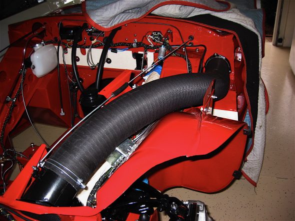
LH fresh Air Hose
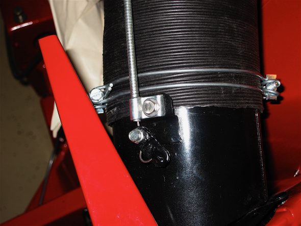
LH Fresh Air Hose

The modern heater (contrasted with the original Smith’s heater radiator box) that I am using from Cape International has it’s own blower fan, and therefore, the original heater blower can be used to circulate fresh air into the passenger side of the cabin. I installed an air intake assembly upside down and close to the front end of the LH hose so the the control cable from the cockpit heater panel could be used to open and close the air inlet valve assembly. It all works like a charm. Perhaps now my victims, I mean passengers, won’t roast while on long sojourns in the summer.
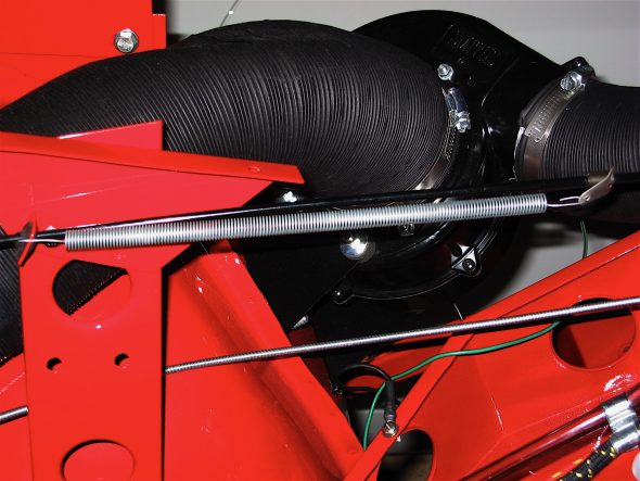
RH Fresh Air Hose to Blower

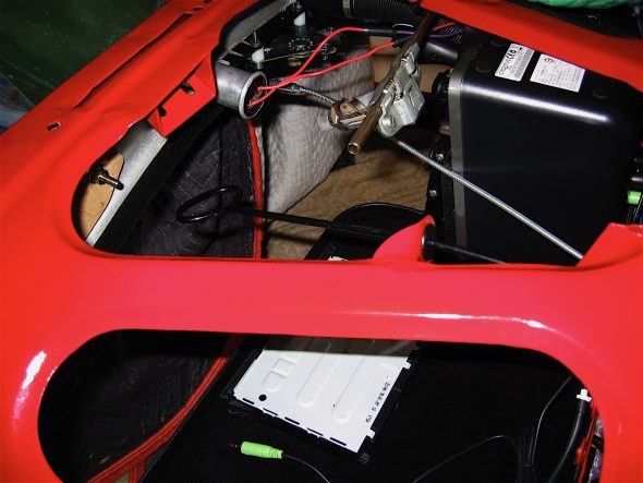
The bonnet catch lever and its connecting rod were then secured to the frame bracket with stainless split pins. Then the anti-rattle spring hardware was attached to the bonnet remote control rod.
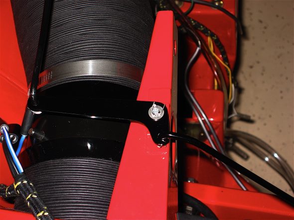
Bonnet Catch Lever & Connecting Rod

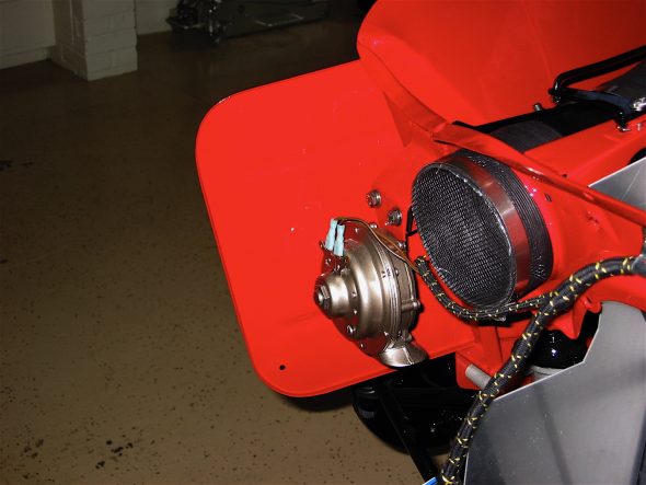
Although the original equipping of the Healey did not provide for any type of screen for the front of the RH fresh air hose (other than the one in the heater blower), I purchased some plastic flexible screen and attached it to the hose with a clamp. This will hopefully keep bugs and small children out of the cooling system. Time will tell how this works.
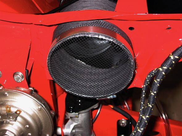
Screen for RH fresh air Hose

Adding fluids and lubrication was next on my list. Many on the email list had suggested using a HELP product #42072to replace the original rubber gasket in the brake reservoir cap to avoid brake fluid “spray” getting to the paint. I purchased and installed the gasket and it does fit perfectly and provides a nice tight seal to the canister.
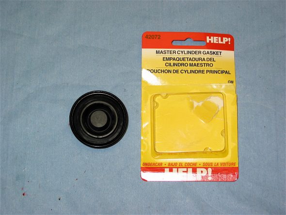
HELP # 42072 diaphragm gasket

I then proceeded to purge the air from the brake and clutch lines by bleeding the system. It is not that this job is hard, but I hate it! Brake fluid is messy stuff and paint does not like it.

Bruce at Healey Surgeons had added steering lube to the idler when he rebuilt it, but now was time to add the lube for the steering box. I used Penrite Steering Box Lube. It is thick stuff. I set the plastic container in a pot of boiling water for a while to heat it up and therefore “thin” it. The container comes with a very handy applicator tube that fit right in the steering box hole. I filled it up and then tightened the fill nut. No leaks the next morning!
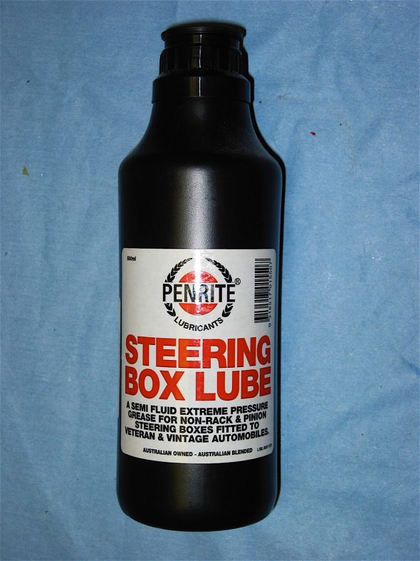
Penrite Steering Box Lube

I found out the hard way that filling the rear axle with gear lube would have been easier prior to installing the rear seats, but with the aid of a clear plastic tube I was able to get 3.6 pints of Valvoline 90 weight gear lube into the rear differential.

Chapter 55 Restoration Assembly, Week Twenty-Five 6/4/2007

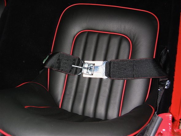
Installing the seat belts was fairly straight forward. I had drilled holes earlier for the mounting kits. I was going to go with the seatbelt/shoulder harness assembly sold by British Car Specialists, but ultimately decided to go with the “vintage look” racing belts sold by Moss Motors. These belts work beautifully with my interior color combination! The shoulder harness kit would have been the best call for safety, but the belt retracting mechanism to be mounted on the rear quarter panels just looked too contemporary. I am pleased with the result!

Seat belts

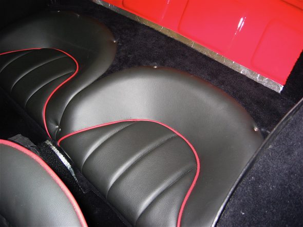
I had been dreading a job, that as things turned out, was not as challenging as expected. I needed to locate and install the #6 stainless screws with trim rings that secure the rear jump seats. I was scared to death that in doing so I would damage the beautiful leather trimming job done by Heritage Upholstery and Trim.

To prepare for installation, I first glued marine class rubber weather stripping around the rear seat tubs. I peeled back the leather on the underside of the seats, located the original screw holes, and carefully punched holes through the leather. A previous owner had used oversize screws to mount the seats and the holes in the superstructure were bigger than they should be for #6 screws so I had the holes filled by Jeremy Turner at Maple Hill Restorations while bodywork was being completed. Therefore, this job required locating new holes in the superstructure and drilling them.

I had Judith, my wife and able assistant, sit in each seat to press it down to the mounting platform and position them as well as possible. I then marked each hole location. I used a 1/8” hollow punch to remove carpet, dynamat and aluminum insulation from each hole location and drilled the holes in the superstructure. Everything turned out great and the installation appears as original. I really don’t care for the look of the stainless screws in the leather, preferring the BJ8 seats that have studs to secure the seats, rather than the screws, but I decided to remain original on this matter.
Rear seat fasteners

Rear seat fasteners

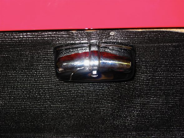
I had never finished the installation of the courtesy lighting in the boot, so it was time to return to that task. I used a rear license plate lamp to supply light and modified the chrome casing to permit more light to enter the compartment. The lamp was wired to the courtesy lights in the interior, so with a flip of the toggle switch or with a click of the remote control “clicker,” the boot lamp is activated.

Boot light

I can’t say why I have not installed the brake and clutch master cylinders and pipes before now? I secured two new master cylinders into the pedal box with the four 5/16” hex head bolts. Aluminum packing shims were used on both master cylinders.

Master Cylinders & Lines

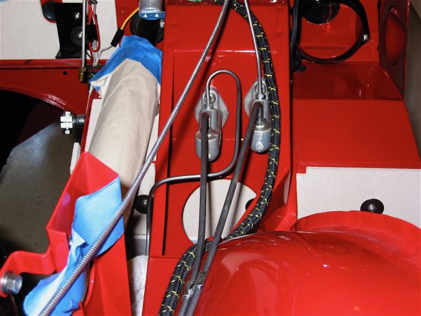
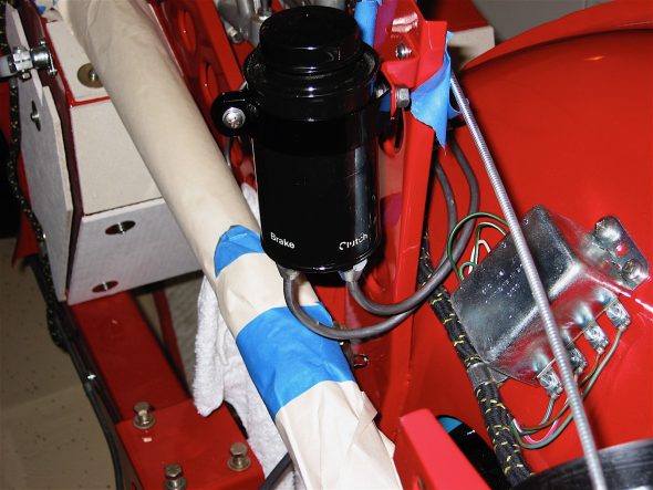
The LH and RH bonnet opening support plates were attached to the frame upright and the brake reservoir was clamped into its bracket on the LH post. The two hydraulic pipes were fitted and the double clamp securing the pipes to the inner fender was screwed in place.

RH Bonnet Opening Support Plate

LH Bonnet Opening Support Plate

Brake Reservoir and lines

Chapter 54 Restoration Assembly, Week Twenty-Four 5/28/2007

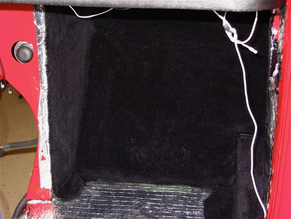
After the LH side rail was carpeted I installed the carpet piece for the driver’s side footbox toeboard. This was the most difficult piece to glue in to the car because it is a little harder to get to (as in standing on your head!) and because it is one piece for two panels. It also incorporates the vertical panel by the gearbox surround. After several iterations of fitting I was pleased with the result and glued it in place. Then on to the RH side.

RH footbox carpet

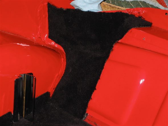
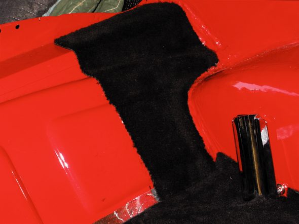
Next came the two pieces of carpet that are glued to the vertical kickboard bulkhead behind the front seats and the rear seat surround. With some minor trimming they fit nicely. I then glued the two small pieces to the LH and RH side of the rear of the car where the soft top and its frame rests when folded down.

RH rear panel carpet

LH rear panel carpet

Rear seat carpet

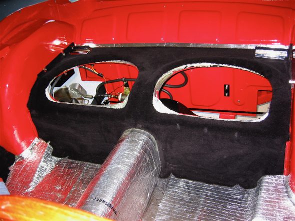
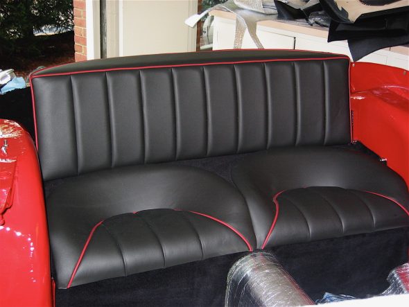
The hardware for the rear vertical upholstered panel was then mounted to the car and the panel was dropped into its position.

Rear seats

 The RH side rail carpet was glued to the rail as per the left side installation.

Heritage Upholstery and Trim provides a piece of vinyl (as per original) to cover the RH kickboard panel as it is an “open” piece. I wasn’t pleased with its appearance so I cut a piece of extra carpet I had to cover the opening and I was very satisfied with the results. It looks much better than the vinyl! I then carefully drilled holes through the LH and RH kickboard panels into the car superstructure and screwed them in place #6 stainless flat head screws with trim rings.

RH Kick Panel

After some trial and error fitting and trimming I put the floorboard carpets in place, cutting the rear most pieces to accommodate the seat rails and their mounting strips. I am going to try using velcro for these pieces rather than snapping them in place since I would have to drill holes in the new floorboards for the snaps. I will see how the velcro works and return to the snaps if my solution is not satisfactory.

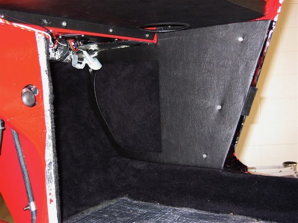
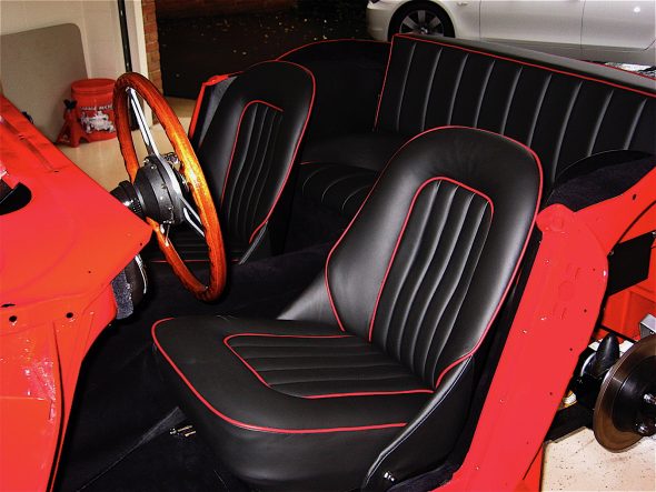
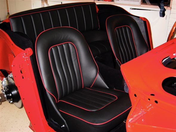
The two vinyl covered rear quarter panels were installed next. Four #8 flat head stainless wood screws were used on the vertical rails and two #6 pan head screws were used on each of the top horizontal panels. The front seats were then put in place and tightened. I installed bolt extensions on the fasteners on the driver’s seat seat rails to slightly angle (tilting rearword) the driver’s seat. This proved to offer a better driving position for me.

Assembled interior

Assembled interior 2

I am going to delay fitment of the gearbox extension cover and gearbox cover carpet until I have the engine and gearbox in the car just to be sure I end up with a good fit.

Chapter 53 Restoration Assembly, Week Twenty-Three 5/21/2007

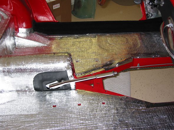
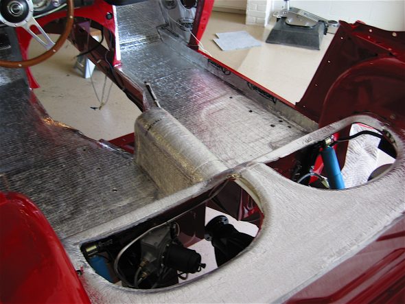
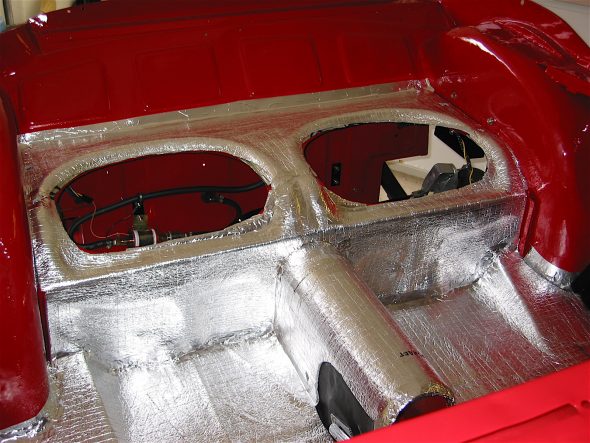
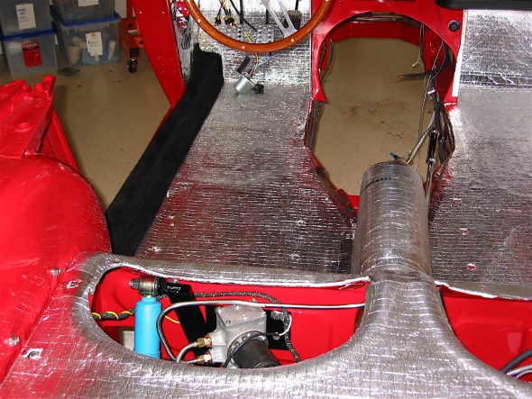
My plan is to devote the next couple of weeks to getting the interior finished. This required completing the dynamat extreme application and then adding an additional layer of aluminum insulation of the type that is used around home duct work. I taped all the joints with aluminum tape which resulted in a nice looking job. Of course, looks won’t matter – all the insulation will be covered by carpet or panels, but it should result in a quieter and cooler car!

Interior Insulation 7

Interior Insulation 1

Interior Insulation 6

I was eager to get a little carpet into the Bloody Beast so I pulled out my carpet installation instructions from Rich Chrysler and the digital images from Heritage Upholstery and Trim. The two together provided all the help I needed. BT7 Carpet Install Rich Chrysler The carpet was also supplied by Heritage. I used the wilton wool option and was very impressed with the quality. The first piece in was the LH side rail. All the carpet was secured with Weldwood brush on contact cement.
Editor’s note, May 2020: Rich Chrysler’s son, Geoff, has followed in his footsteps. Geoff has his own interior trimming business named Rightway Heritage Trimming. In addition to his trimming business, he also is currently involved in the restoration of his own 1953 BN1. He keeps an on-line Blog with information about his business projects as well as his own restoration. He posted the following information which provides superb guidance on the installation of a BT7 interior. This link will direct you to a pdf file of the post. Geoff Chrysler BT7 Trimming

Interior Insulation 4

Chapter 52 Restoration Assembly, Week Twenty-Two 5/14/2007

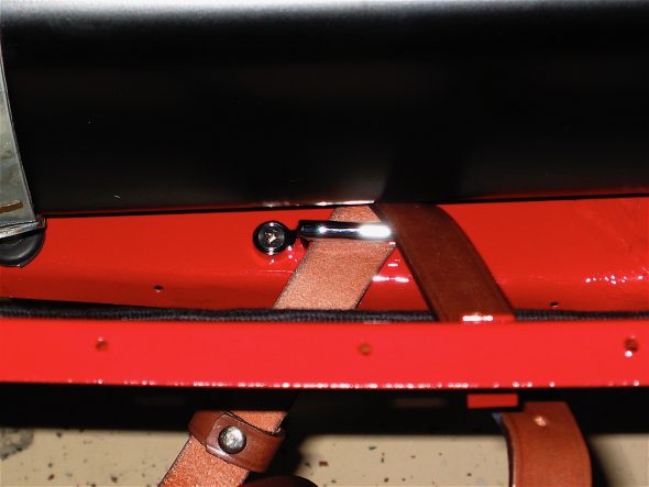
After a few gorgeous days on at the Chesapeake Bay, I am back at finishing the boot. I glued down the left Armacord panel that covers the trough and extends to the rear shroud. I am going to wait on the right one, under the battery, until the shroud is mounted. The new aluminum fuel tank was then put in place. The pipe connection to the fuel line was made at the rear of the tank, and the two securing straps were bolted down.

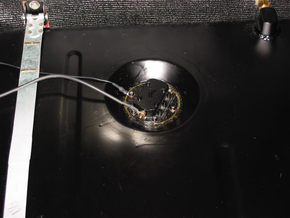
At the suggestion of other British Car Forum members, I added a ground wire from the fuel sending unit to the frame and I connected the power wire to the sending unit terminal.

Fuel sender wiring

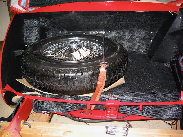
The spare tire staple was mounted to the floor of the boot with two flat head machine screws and the leather strap was inserted. I put the spare in place just to see how things would look and fit.

Spare tire staple

Spare tire installed

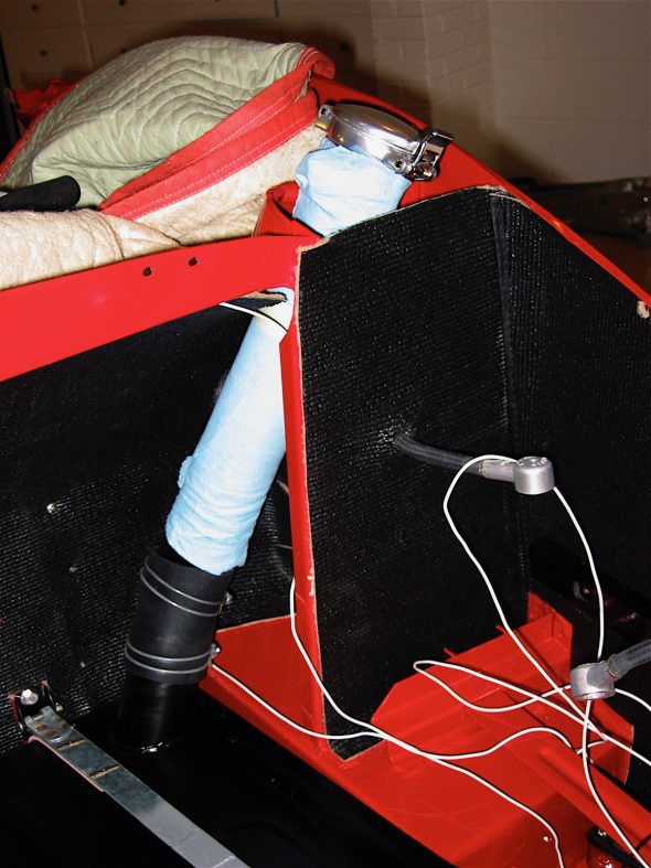
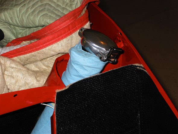
Next, I moved to installing the fuel filler neck hose and the filler neck (pipe). I tightened the lower clamp, but will wait until the shroud is installed to finally secure the upper clamp. The blue paper towel in the image to the right is just there to protect the paint until final assembly. The Aston fuel filler cap was screwed on and the corner cardboard cover was screwed on with six #6 screws and trim cups.

Fuel filler pipe

Aston Filler cap

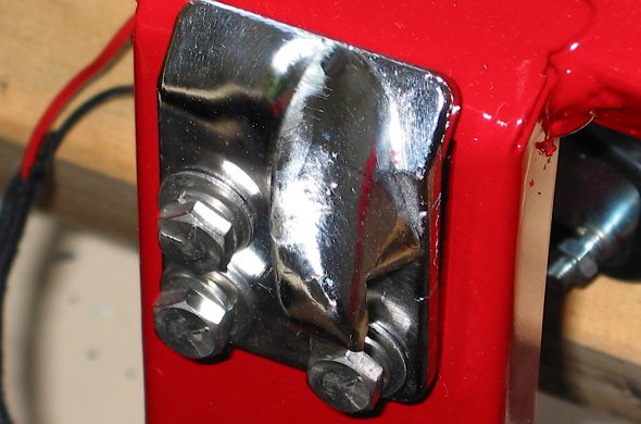
The boot lid striker was then loosely attached to the rear skirt rail support with three 1/4” hex bolts. It will be tightened in place following the installation of the shroud and the rear boot lid.

Boot Lid Striker

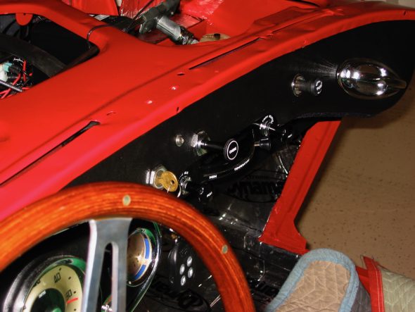
The choke knob and cable were the next items to be addressed. The original BT7 had its choke located below the dash, but as with later cars, I decided to place mine on the dash fascia. Because my only option was to drill a round hole in the fascia, rather than the stamped hole on the later cars with a “flat” at the top of the hole to hold the cable unit when tightening the nut on the back side, I improvised with a chrome nut on the front of the fascia as well. I actually made it by cutting off the back of an extra side curtain bezel. It fit perfectly and won’t be recognized by the untrained eye.

Choke Knob 2

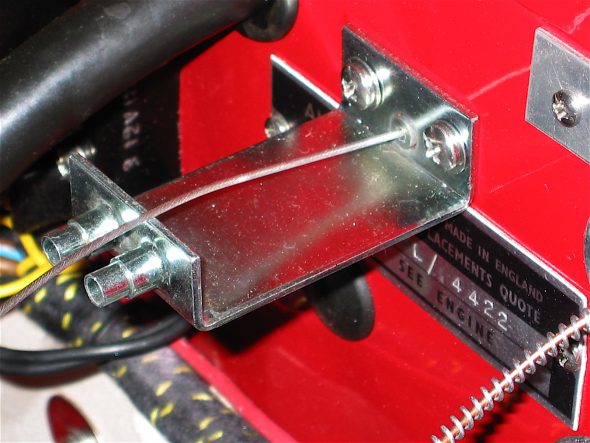
Since I am using 2” HD8 carbs instead of the stock HD6 carbs, I also used the BJ8 choke control body bracket mounted on the firewall. Other Healey owners have reported problems with the return mechanism on the choke, so I drilled the remote control cable block and tapped the holes for two #4 stainless screws to secure the carb cables in their fittings.

Choke Control Body Bracket

Choke Cable Block

The LH fresh air intake assembly was then installed, and the control cable was attached.

Air Control Assembly 1

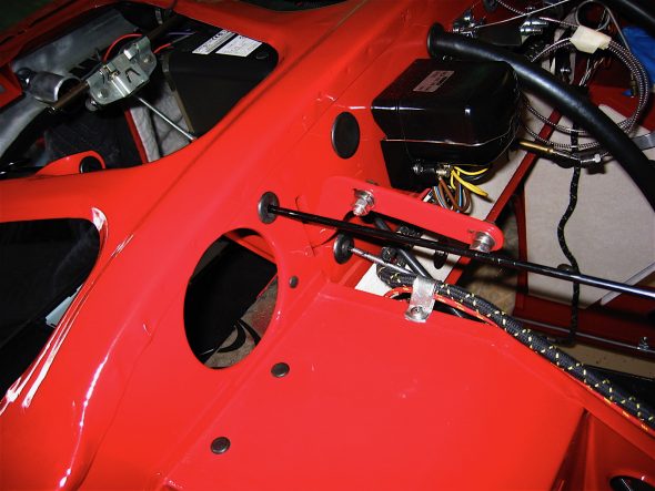
The bonnet latch remote control rodwas the next item to install. While it wasn’t a problem, it would have been easier to install before the dash fascia was affixed!

Hood latch remote control rod 1

Hood latch remote control rod 2