Two more little jobs need to be accomplished in my journey to “renew” the Healey:
Vinyl Door Piping
After a little over ten years of use, the vinyl piping that edges the aluminum trim plate on the passenger side door shut face pillar was just worn out. My rear door gap is a little tight and the vinyl piping sometimes gets caught as the door closes.
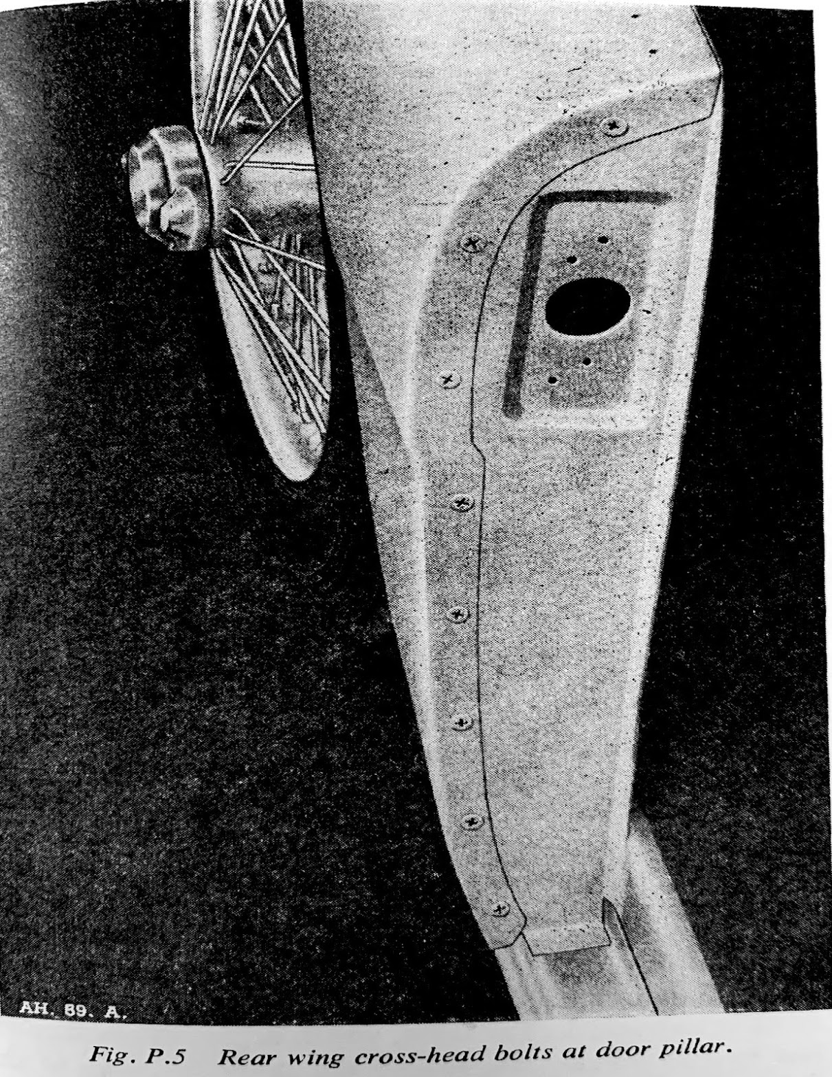
According to Anderson and Moment’s book, Austin-Healey Restoration Guide, the bottom and rear door sills were covered with aluminum trim plates, textured in a raised pattern. A vertical section covered the shut face pillar, secured to the pillar with eight chrome Phillips screws, 54K3024, #28 in the illustration.

Shut face Pillar
Black grained vinyl piping separated the rear trim plate from the rear fender along the door opening. This piping extended up and over the trim panel with its core removed so that it wouldn’t catch on the edge of the door when opened and closed.
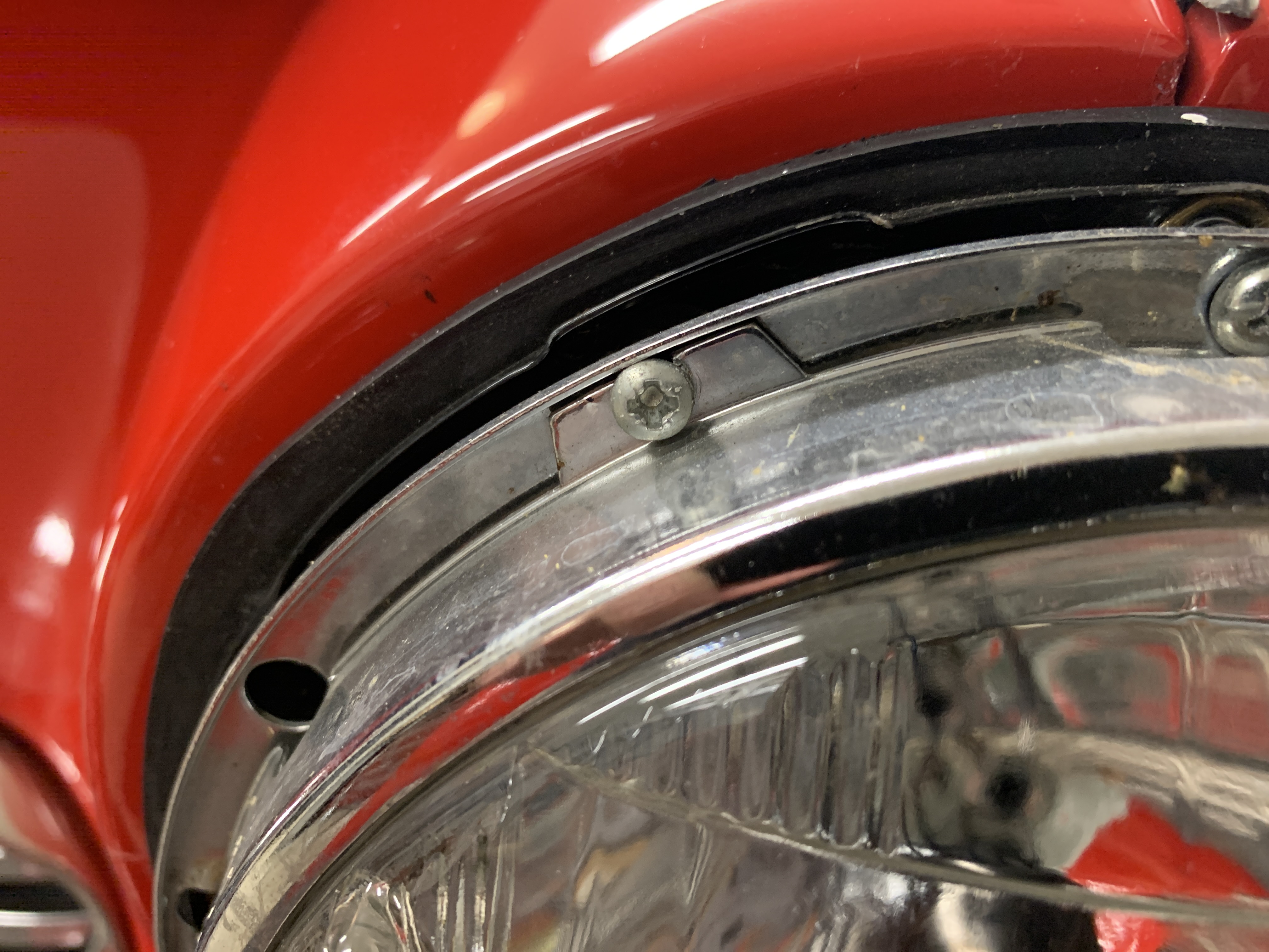
From the Concours Guidelines: From the introduction of the Abingdon BN6 through possibly the end of BJ7 production, the shut facing was fastened with small, #4 truss-headed Phillips screws with very small cross- head screwdriver slots. Starting around 1963 or 1964 the screw head was changed from Phillips to Pozidriv.
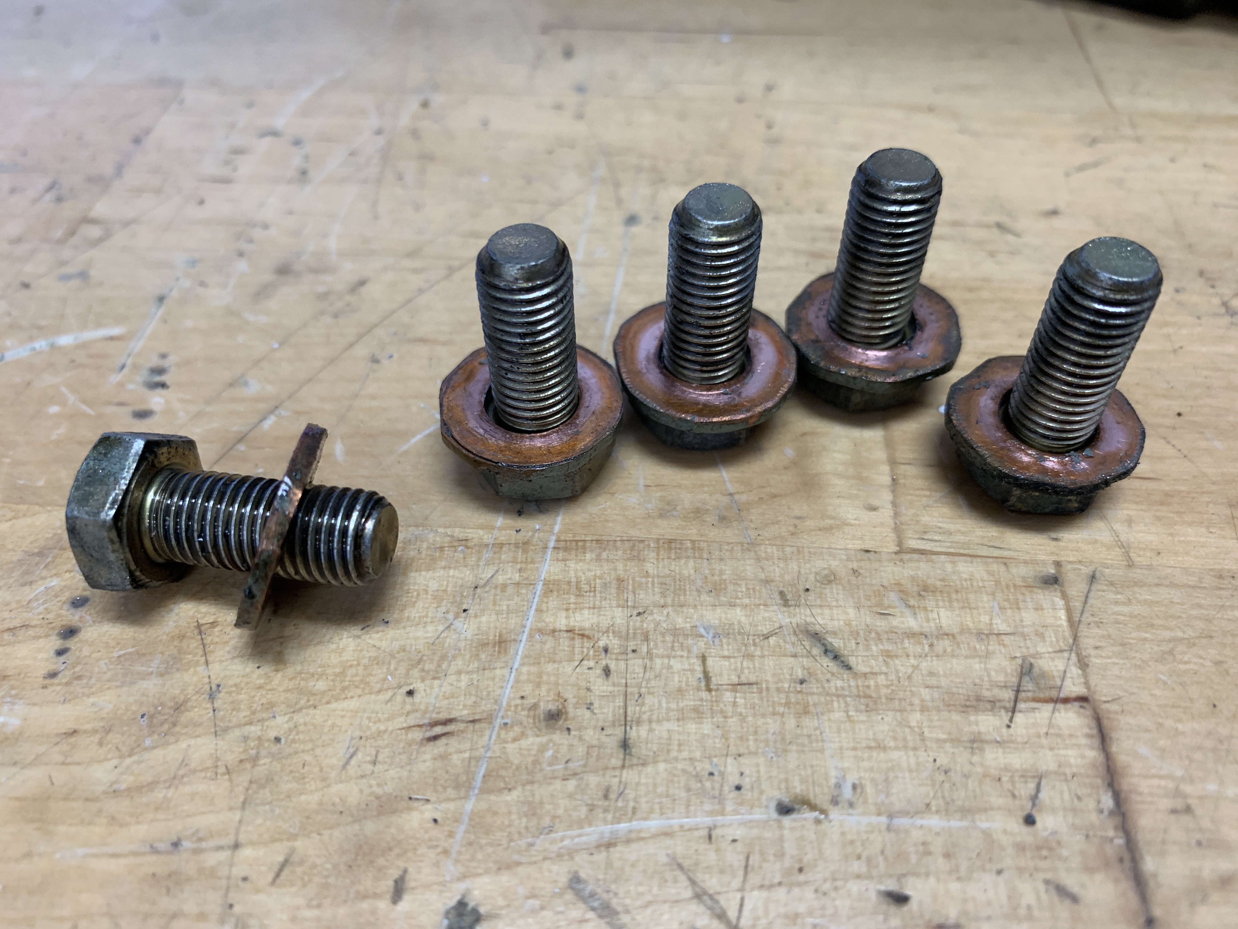
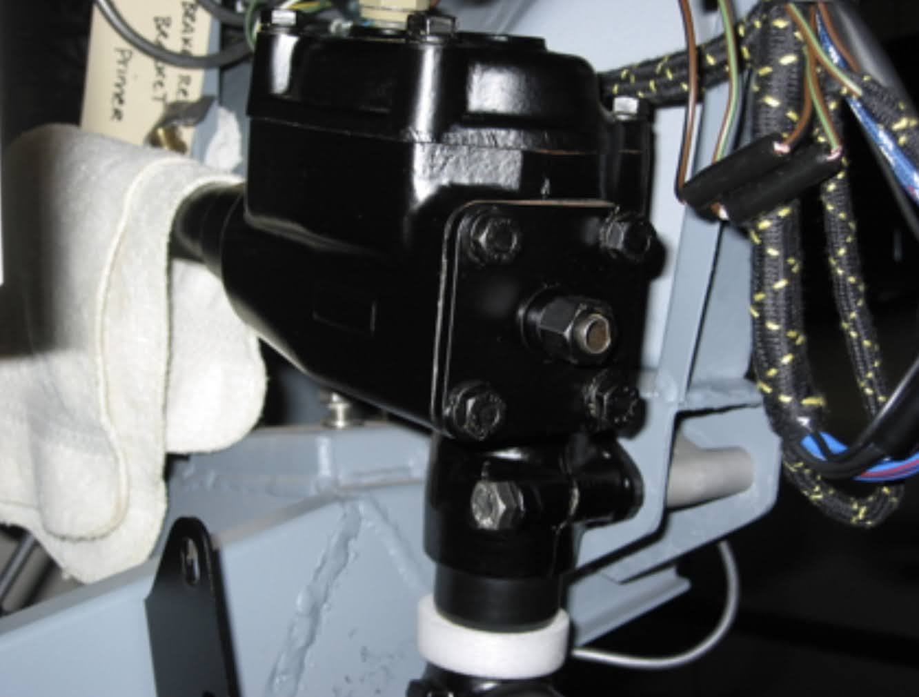
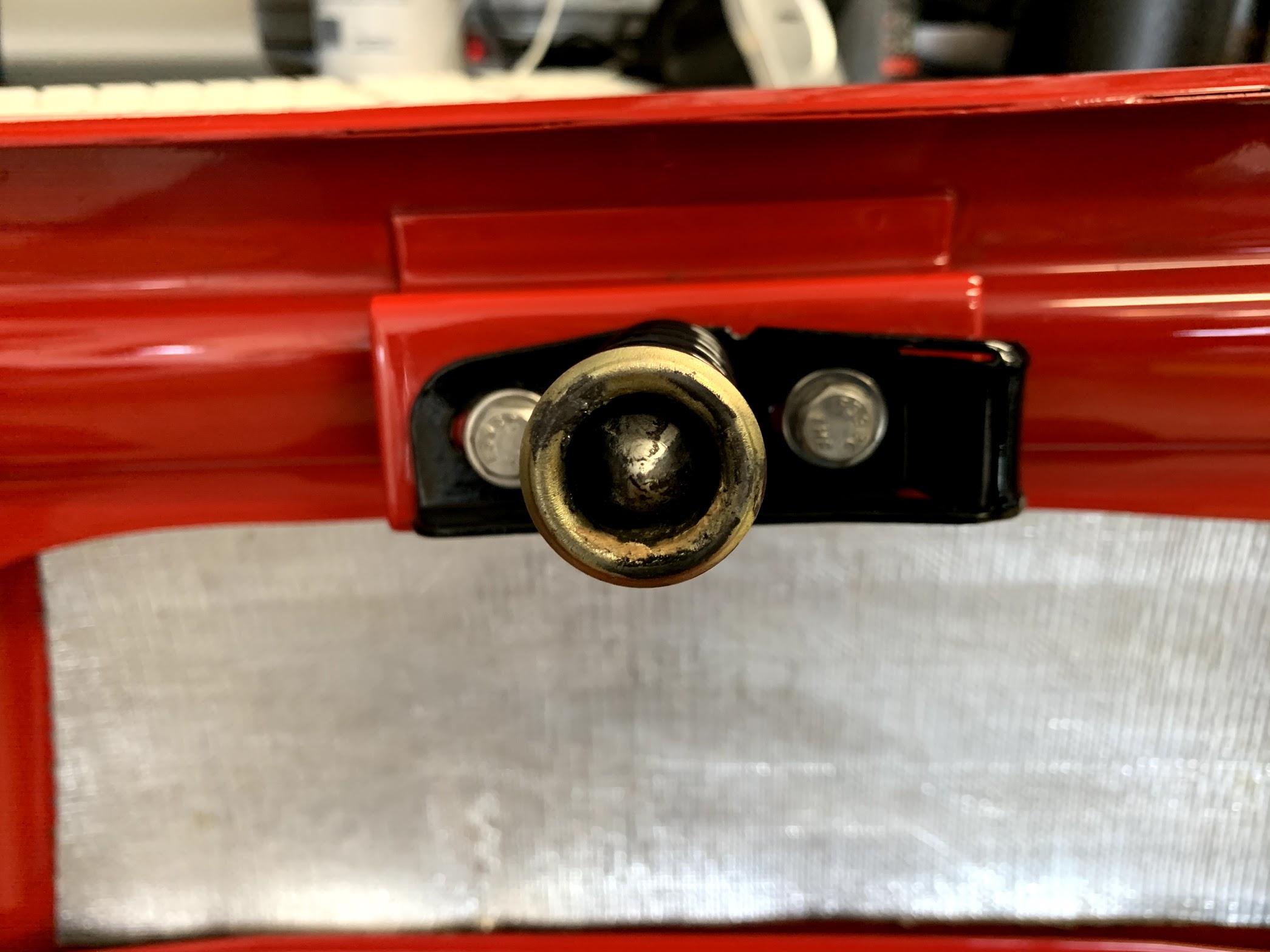
To remove the aluminum trim plates, one must remove the door lock striker, 14B2841, #31; that is attached through the door shut face pillar and packing plate, 14B2842, #32, into a tapped plate, 14B2843, #33. The assembly is secured with four chrome Phillips Head striker fixing screws, RMP0312, #34 (#10 x 3/4”)
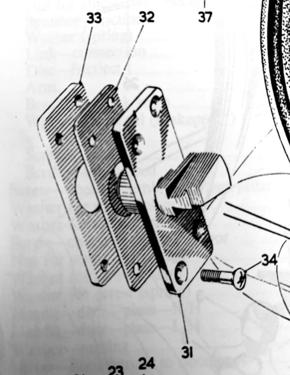
Door Striker Assembly
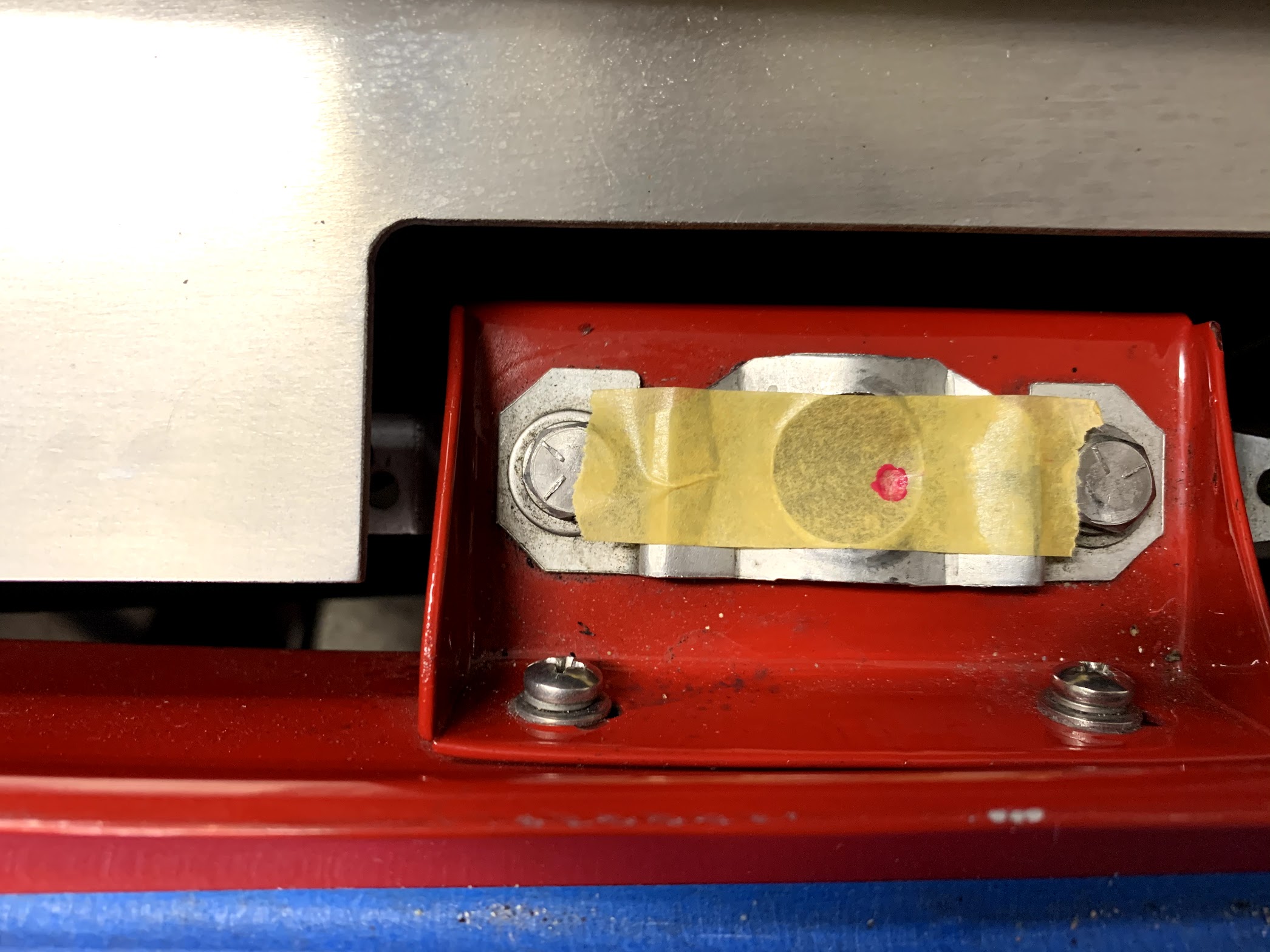
The striker assembly is adjustable so to be sure to return the assembly to the same position once reassembled, tape was used to mark the outside edges of the striker on the aluminum trim plate.
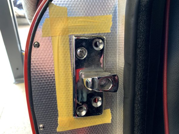
Marked Position of Door Striker Before Removing the alloy trim
I removed the striker plate assembly by loosening the 4 Pozi Drive screws.
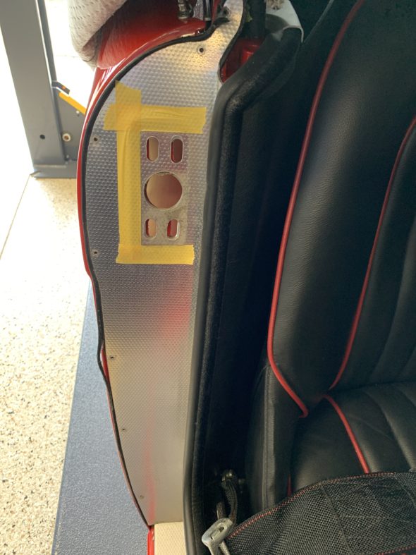
Door Lock Striker Removed
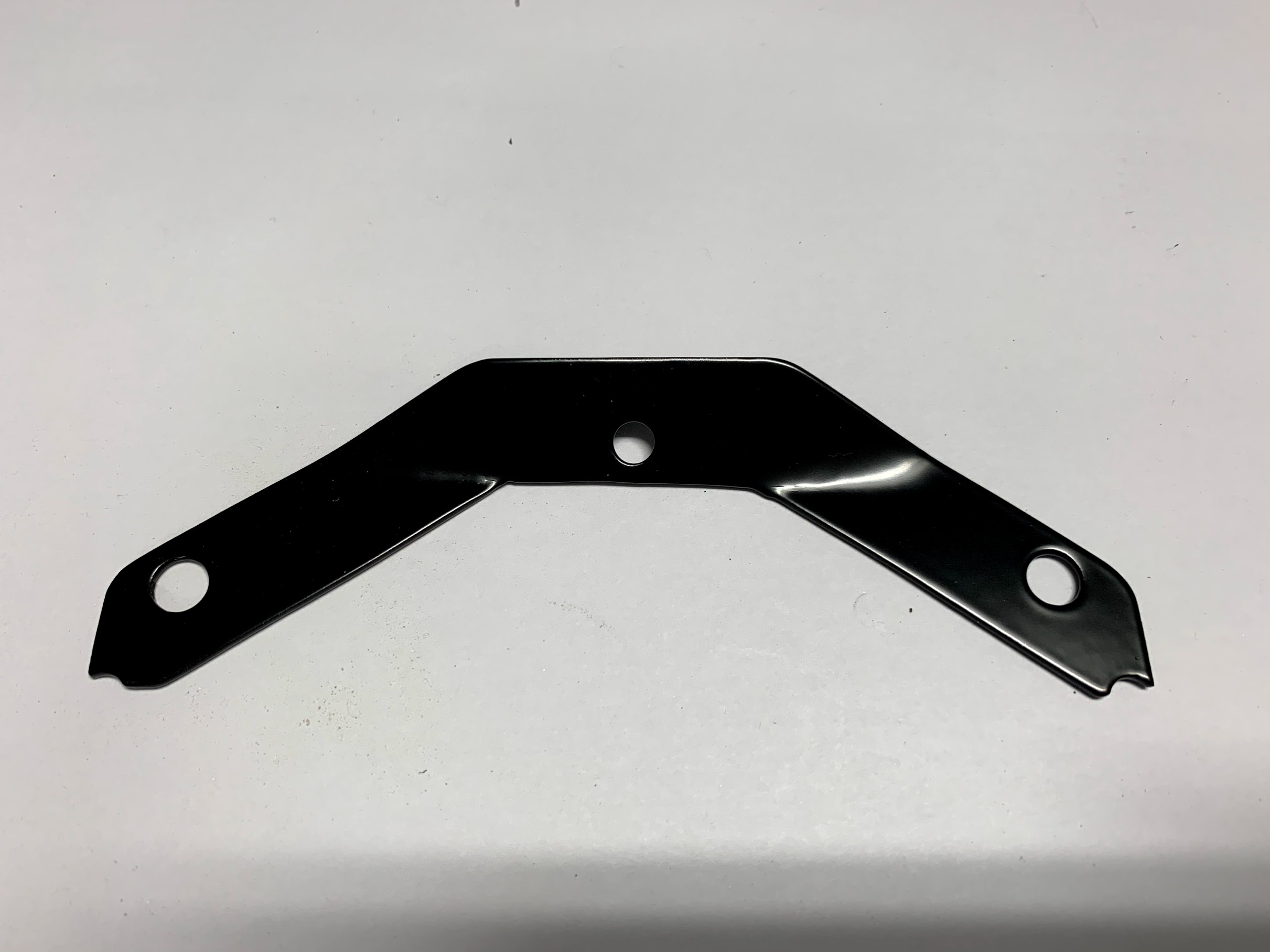
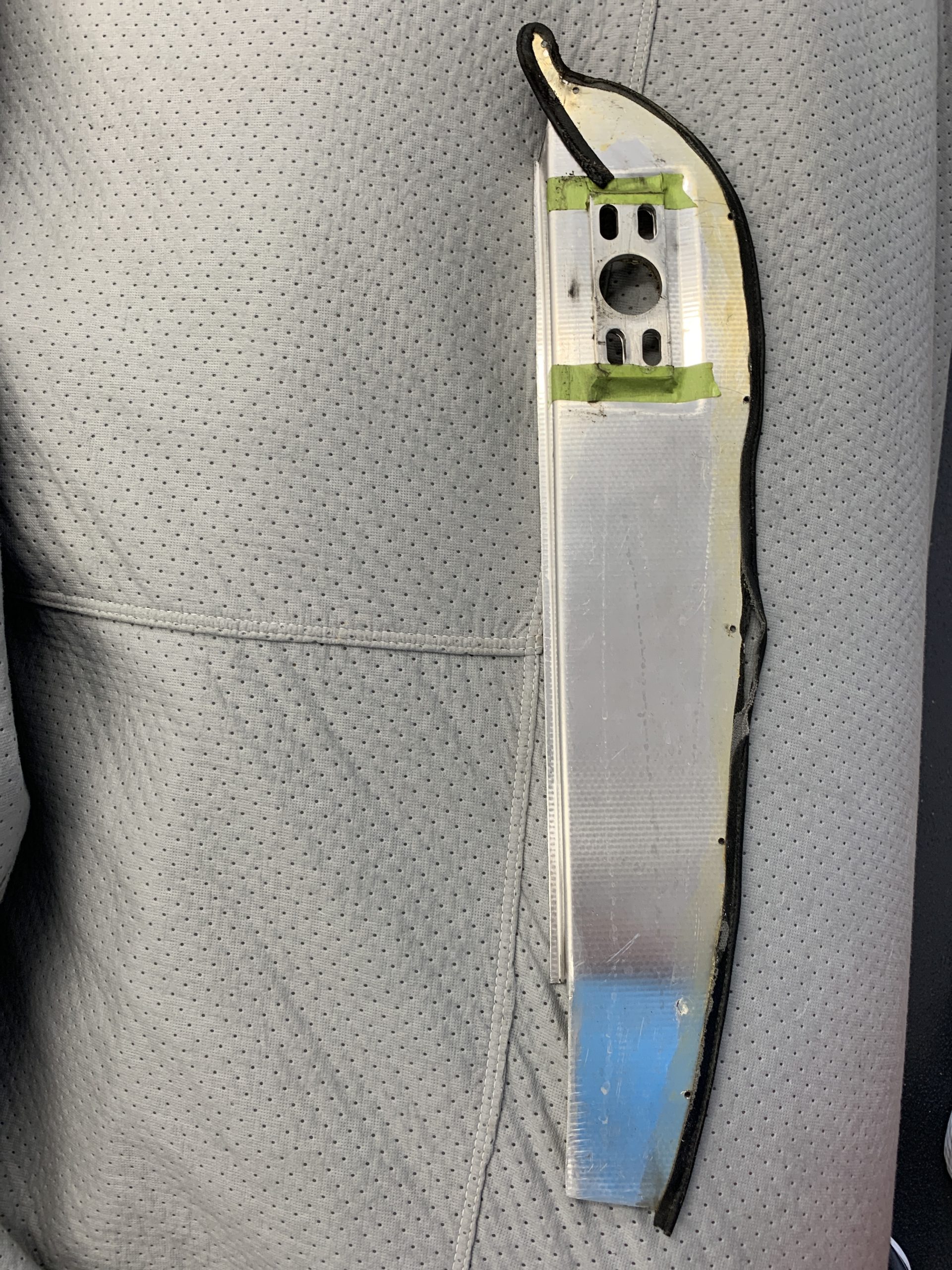
I then removed the seven #4 Phillips head screws that secure the aluminum trim plate to the door shut face pillar. The trim plate could then be removed. The image below shows how the piping is glued with contact cement to the trim plate before reinstalling.

Reverse Side of Alloy Trim Plate
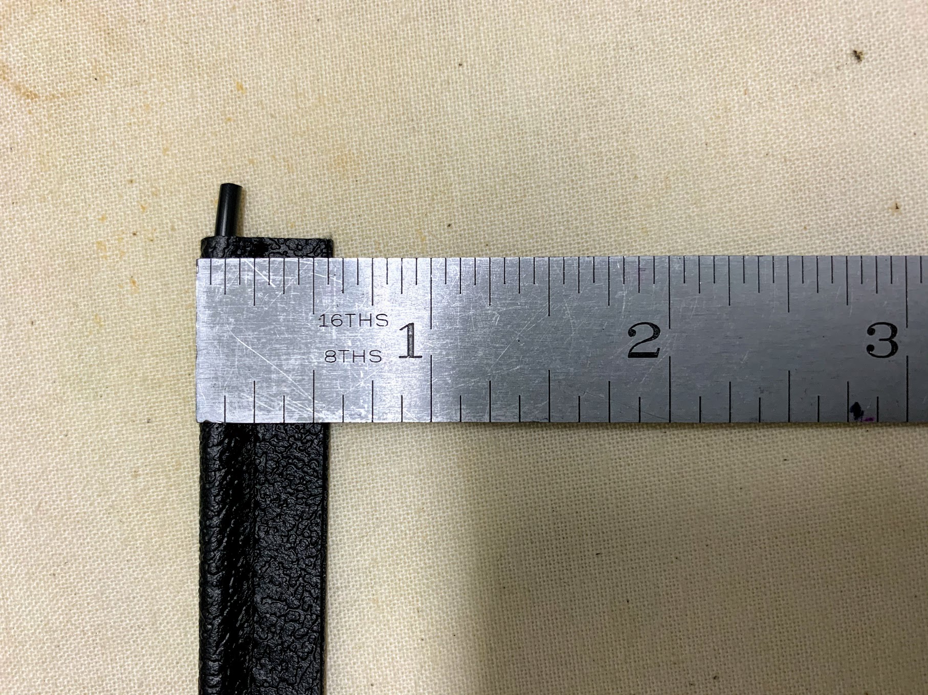
Geoff Chrysler, owner of Rightway Heritage Trim, made a pair of the piping pieces for me that are the proper size.
Chrysler Vinyl Trim
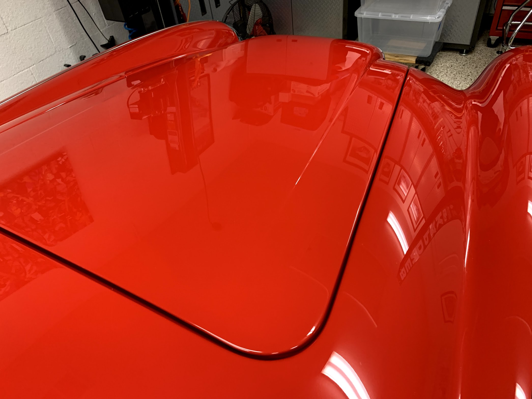
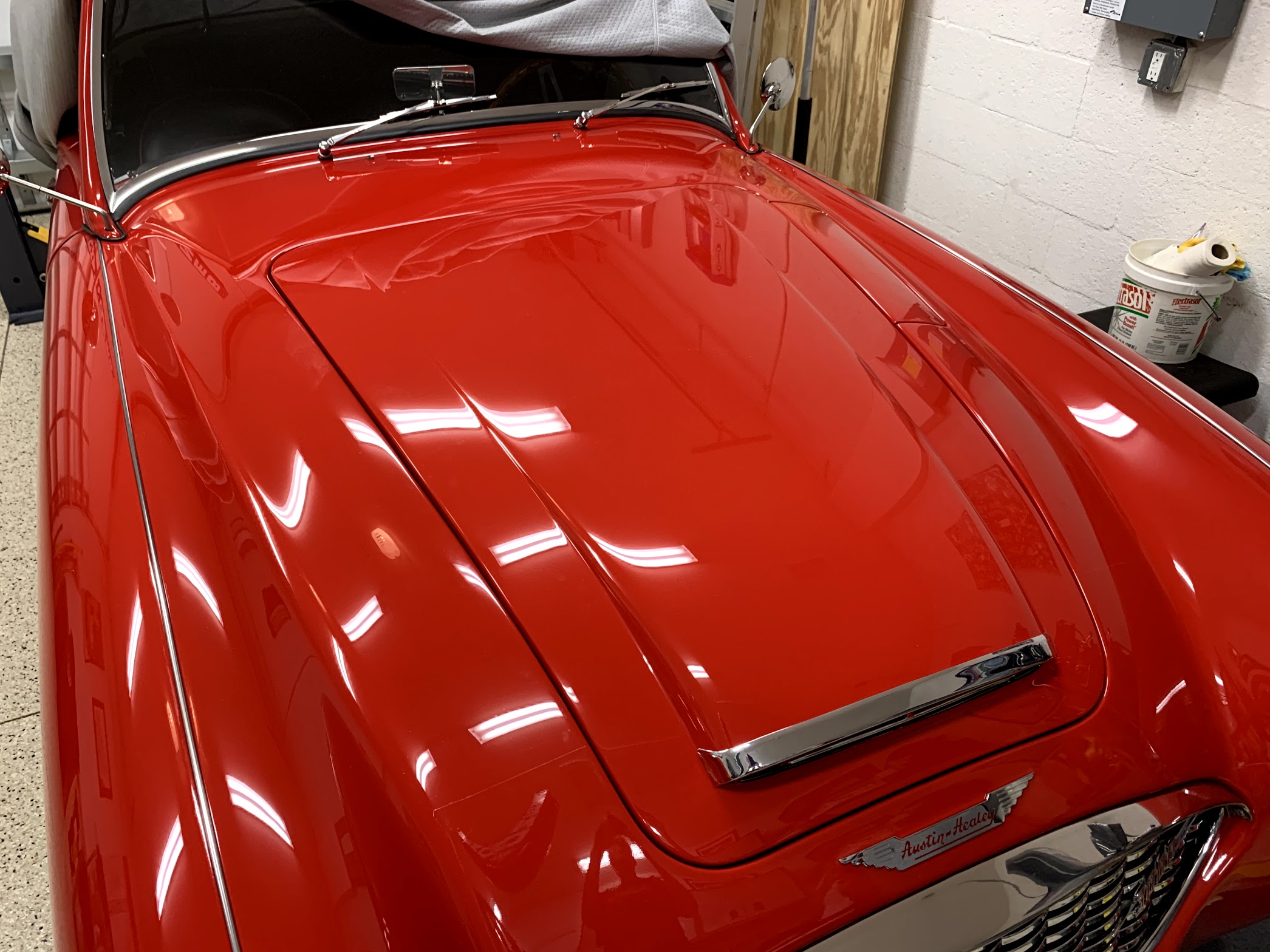
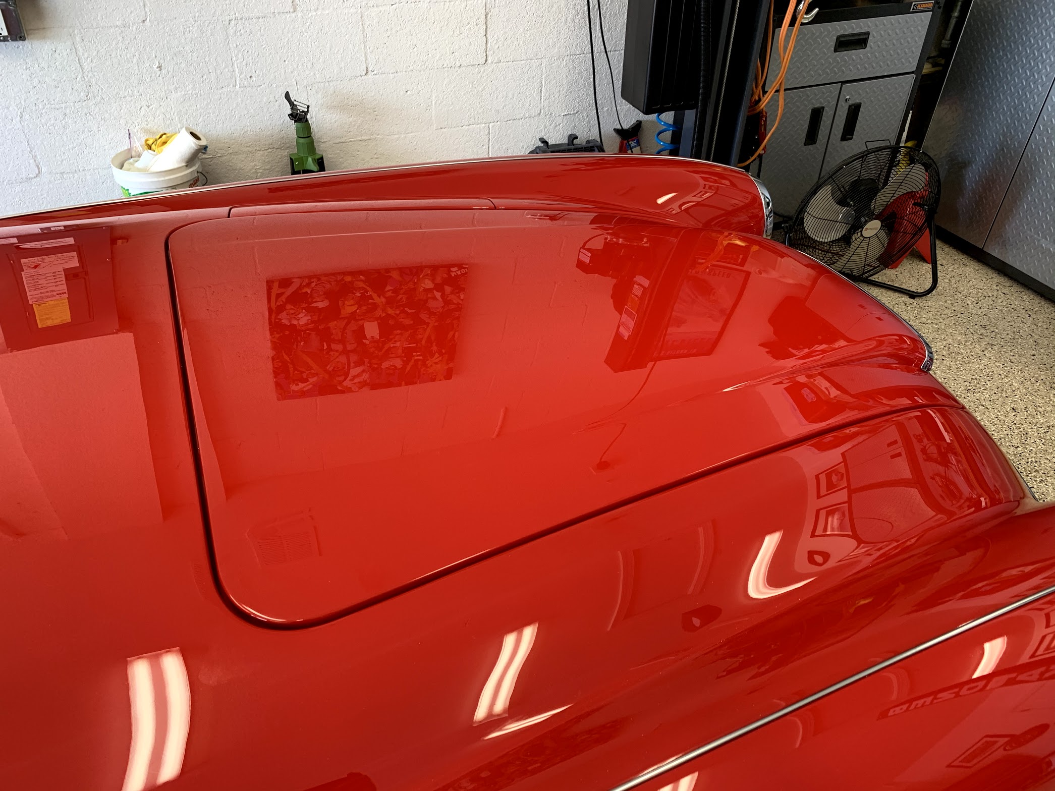
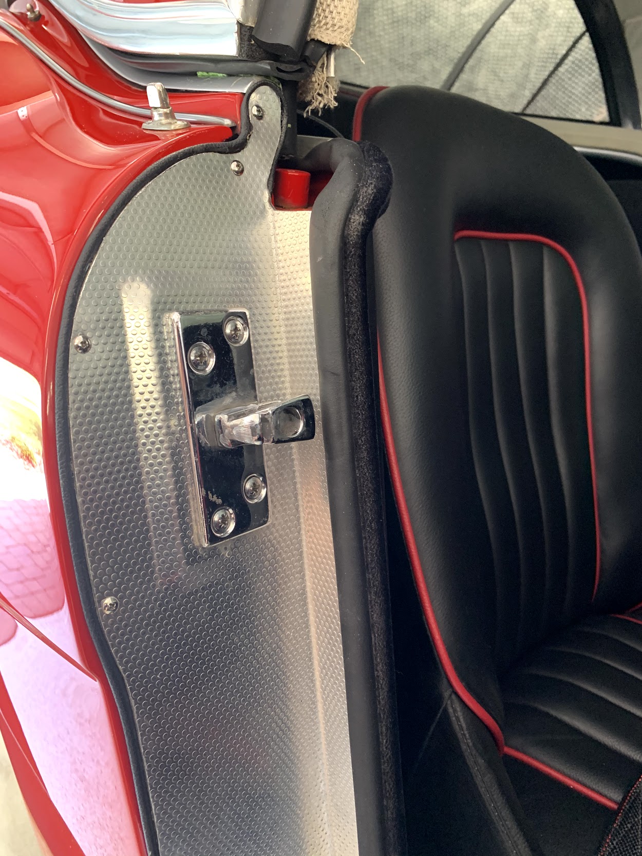
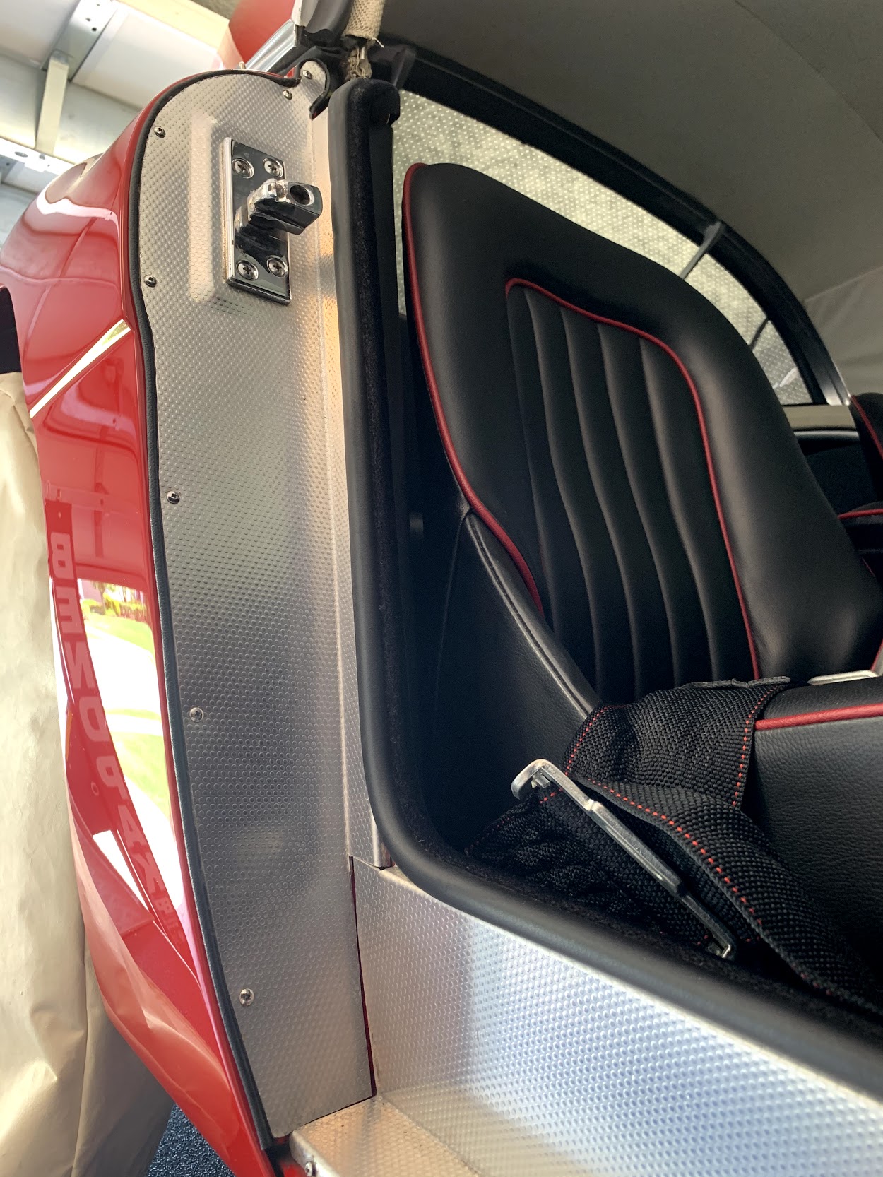
I glued the piping to the plate and then remounted the plate on the pillar. The turn at the top of the trim plate is difficult to address and it does take some patience. This is the finished product reinstalled on the car.
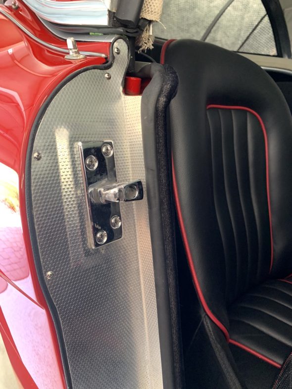
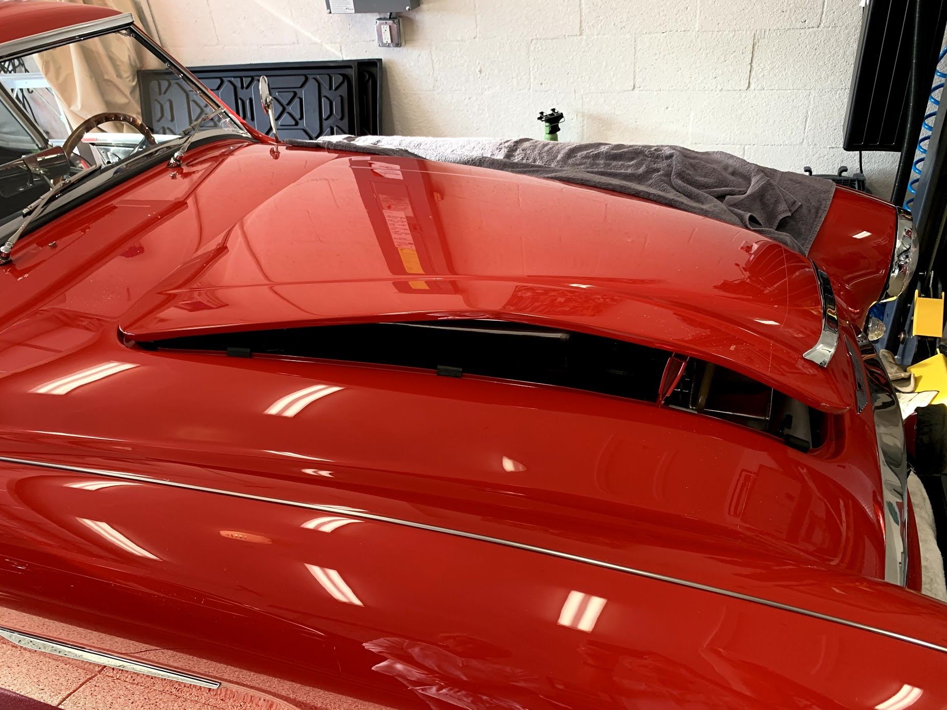
Vinyl Piping on Door Shut Face Pillar Alloy Trim

Vinyl Piping on Door Shut Face Pillar Alloy Trim
Ignition wiring
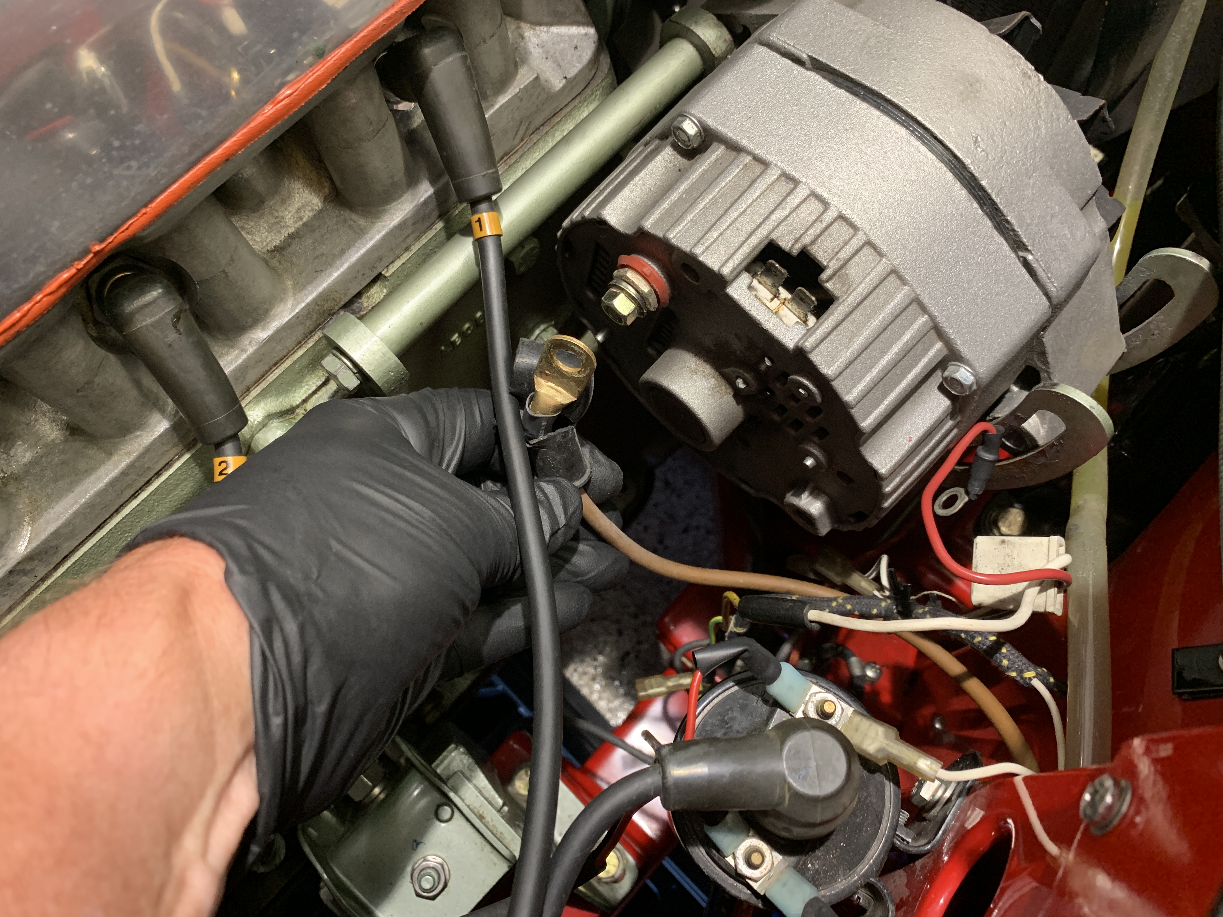
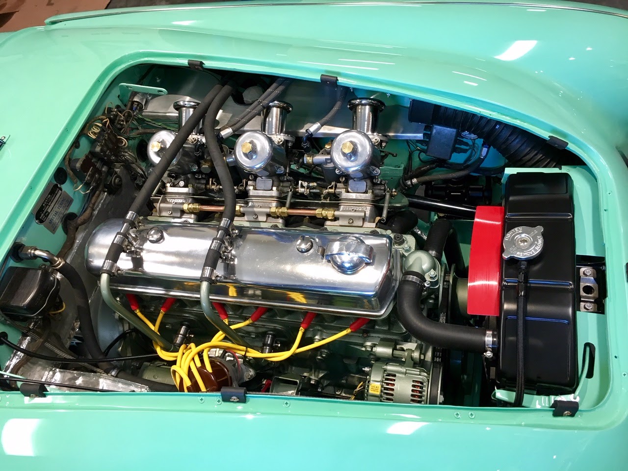
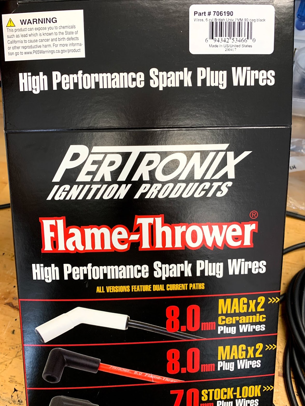
The ignition wiring for the coil, distributor and spark plugs was operating perfectly but I thought as a preventative maintenance item I would go ahead and replace the wires so I would be good for another ten years. This included replacing the distributor cap and rotor on the 1-2-3 electronic ignition device. I used the same type of wiring installed on the car when it was restored. The product is made by Pertronix and is designed for use with electronic ignition systems.
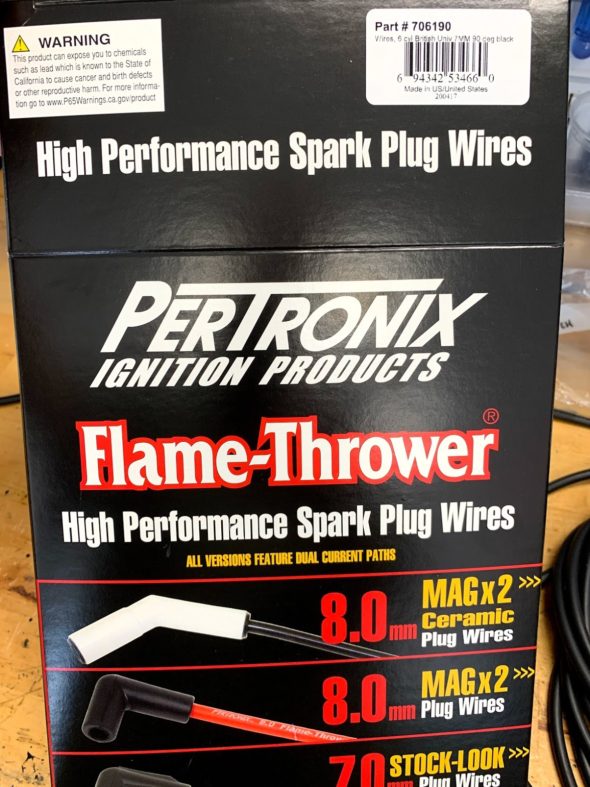
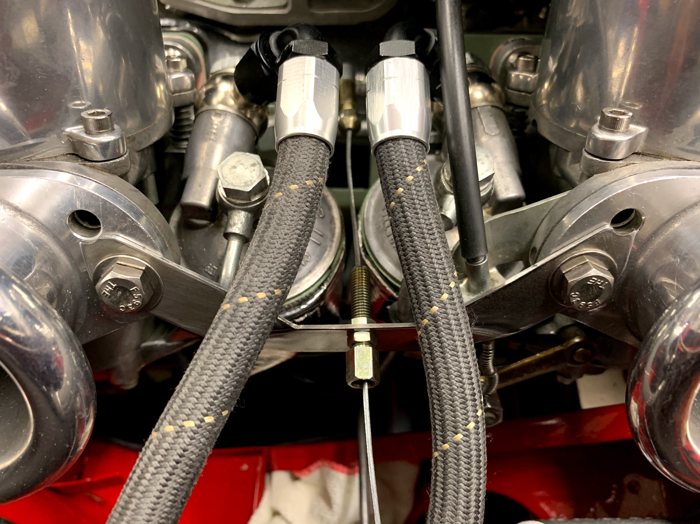
Pertronix Spark Plug and Coil Wires
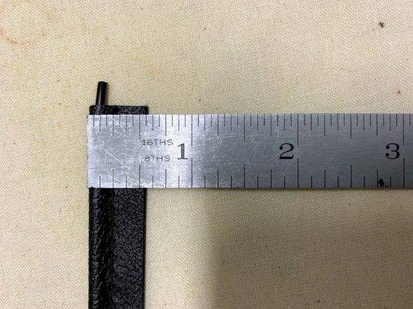
As supplied, the spark plug terminals and boots are already mounted on the individual wires. One only needs to cut the wires to length and install the terminals and boots for the distributor end of the wires. To make the job a little easier I used a wire/insulation cutter made by Petronix for the task. It works perfectly and leaves a nice clean core to wrap around the terminal.
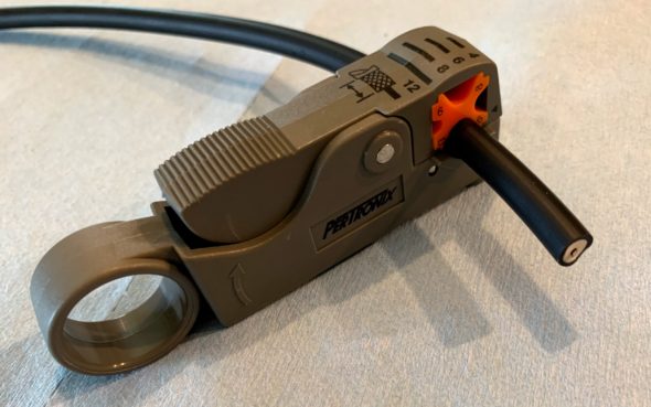
Pertronix spark plug wire Insulation stripping tool
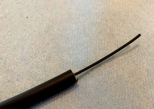
New Spark Plug Wire Trimmed
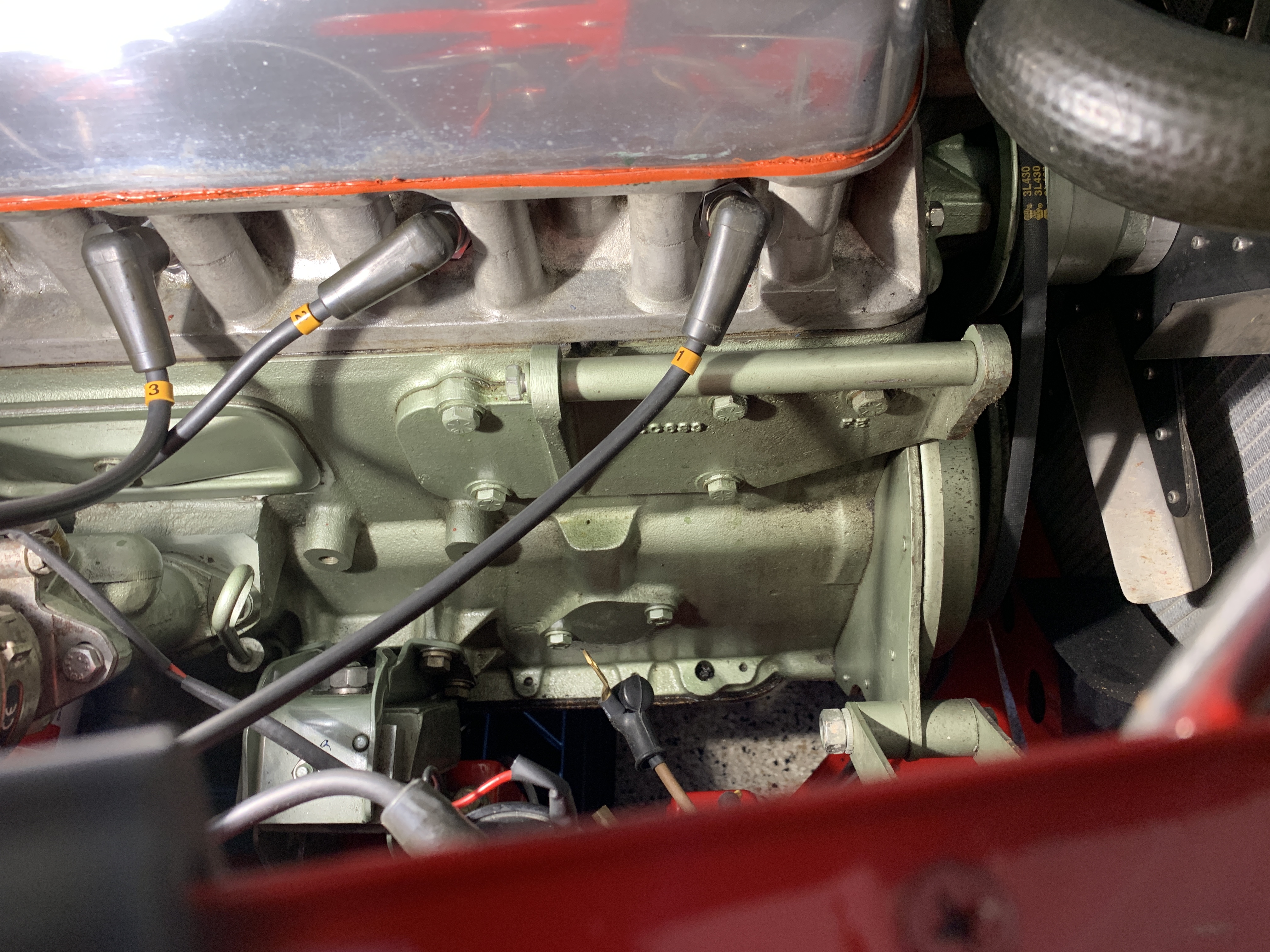
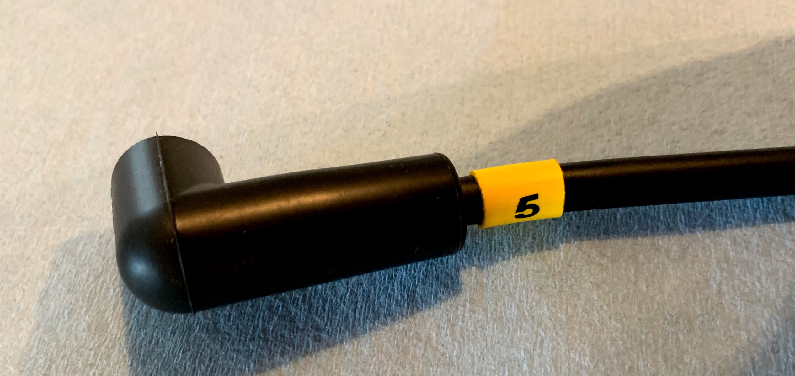
I also installed heat shrink wire numbers on the wires to help with sorting the wires.
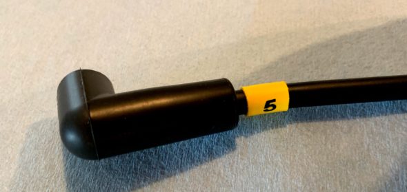
Pertronix Spark Plug Wire Boot and Number
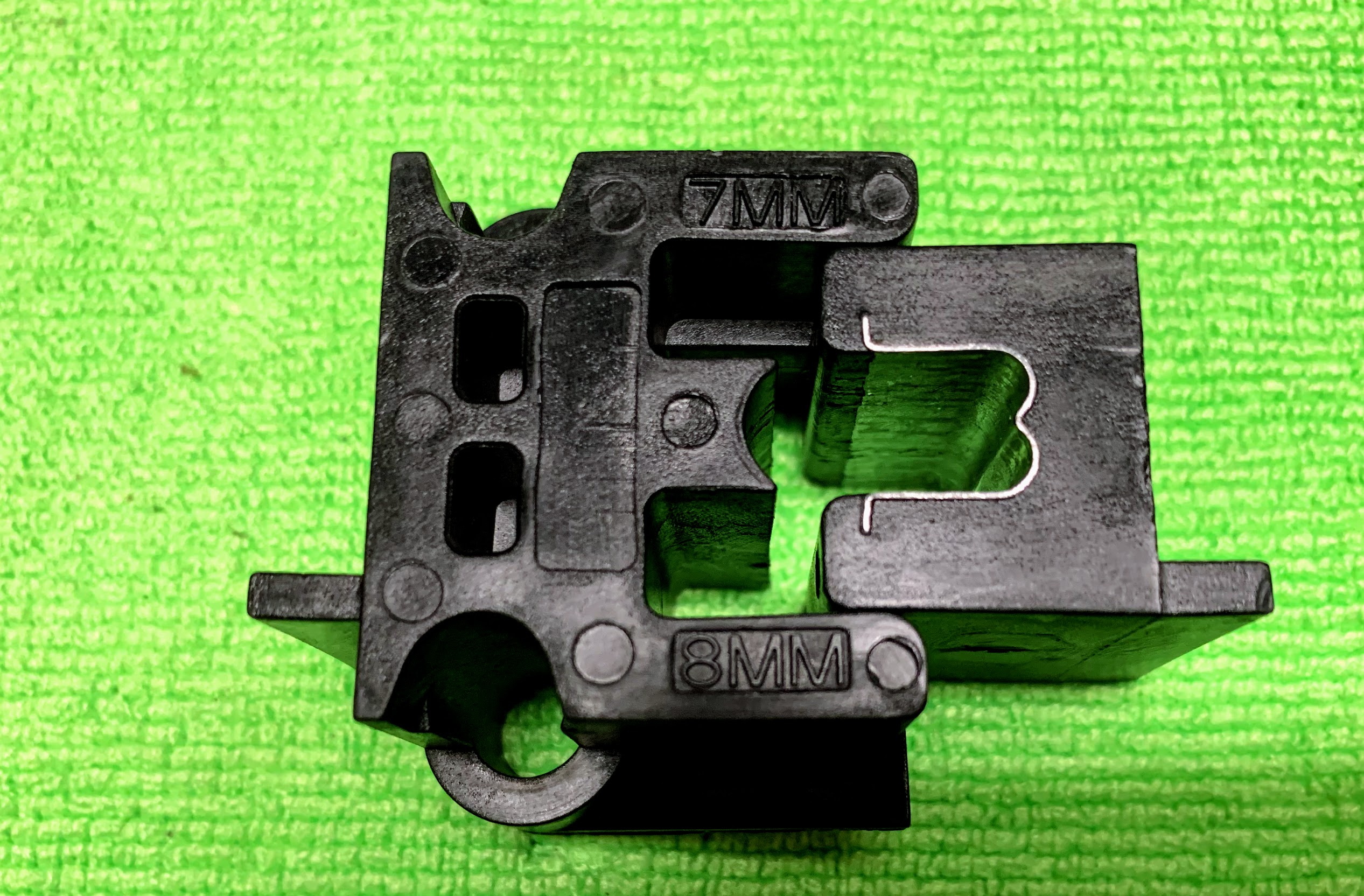
Pertronix also sells a two piece crimper used to crimp ignition wire terminals to the cable. It works for 7mm and 8mm wires, and produces perfect crimps every time. One places the terminal and wire between the two pieces of the device and then tightens them together in a vice.

Ignition Wire Crimper
All the new products were installed and the car is running just fine.