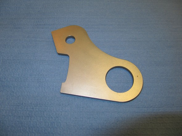
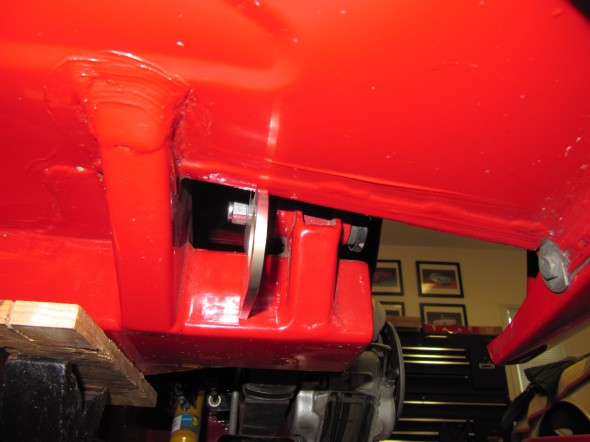
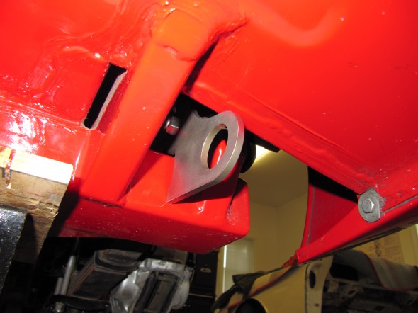
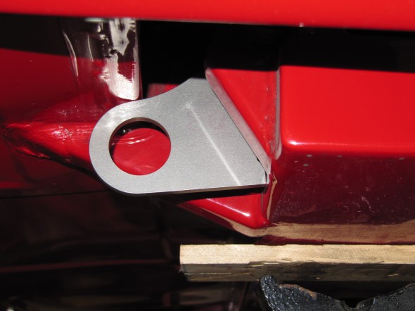
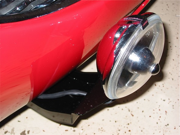
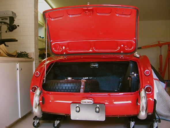
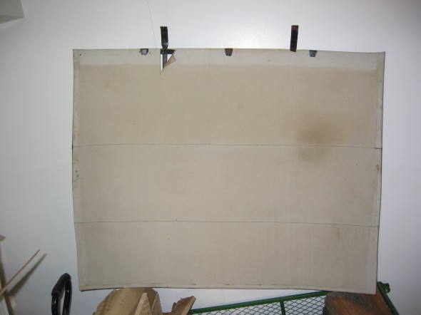
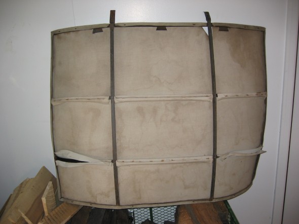
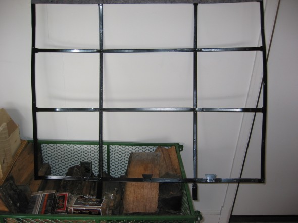
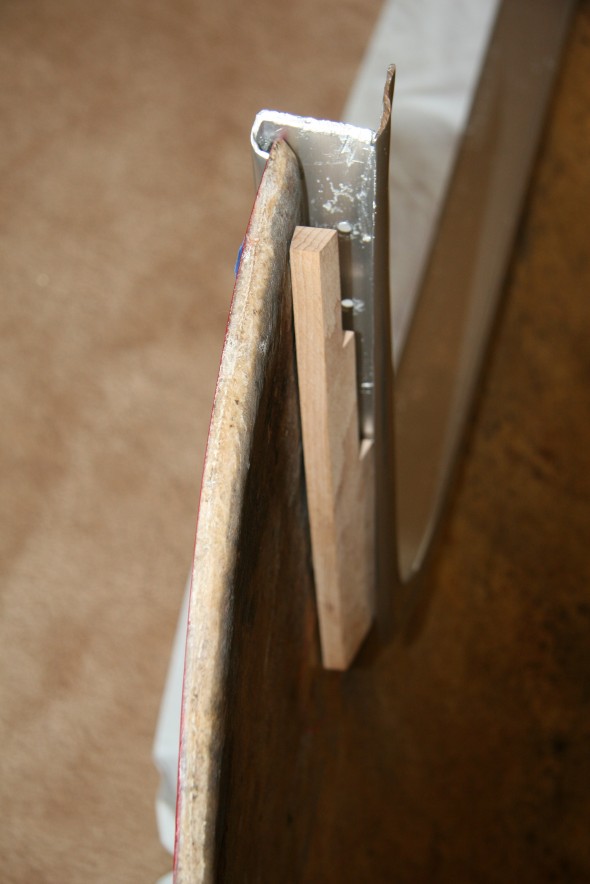
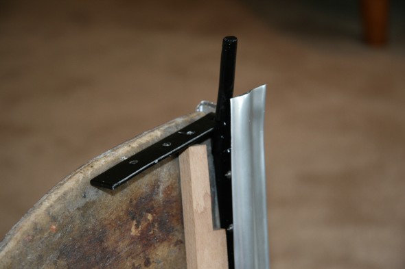
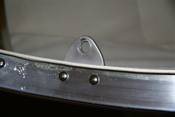
I noticed on the Tom’s Import Toy Sales http://www.tomsimport.com/new/parts/parts.asp?sect=20&new=1 web site that he sells a nice replica of the factory tow hooks. They are made of high grade stainless steel and fasten to the car using the rear leaf spring bolt. I ordered a pair and was quite pleased with the quality. See images below:
Daily Archives: March 15, 2020
Brakes
The front drum brakes of the 100-Sixes were replaced by Girling 11” disc brakes on the 3000 in March 1959. Rear brakes were 11” Girling drums that were also controlled by a handbrake lever located on the right side of the gearbox tunnel
Brake Modifications
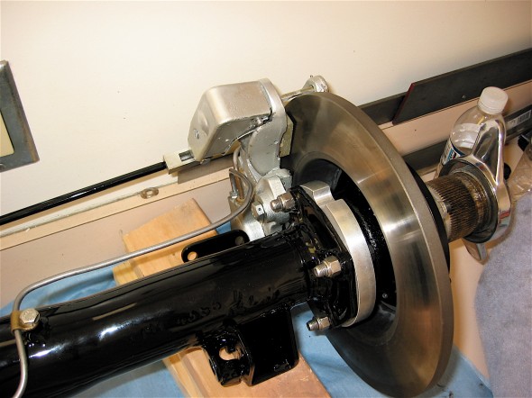
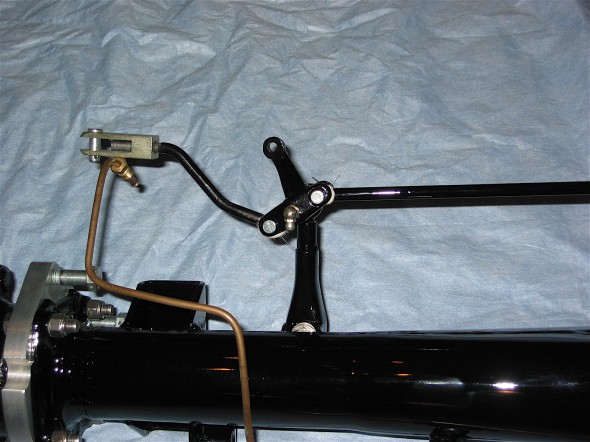
The most significant modification I made to the braking of the 1960 MKI was the conversion of the rear drum brakes to disc brakes. This was accomplished with a kit based on Jaguar calipers coupled with mini-handbrake calipers sourced from Cape International. New rods to connect to the balance lever are supplied so that the handbrake functions as original. This is a pdf file of the instructions provided by Cape International.Cape Int Disc Brake Conversion 1
Aeroquip Braided Stainless Steel Hoses
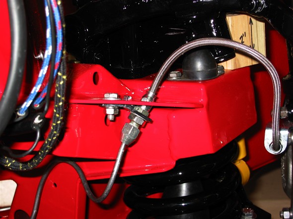
Original-style rubber brakes hoses were replaced with stainless braided hoses also sourced from Cape International.
Drilled Front Brake Rotors
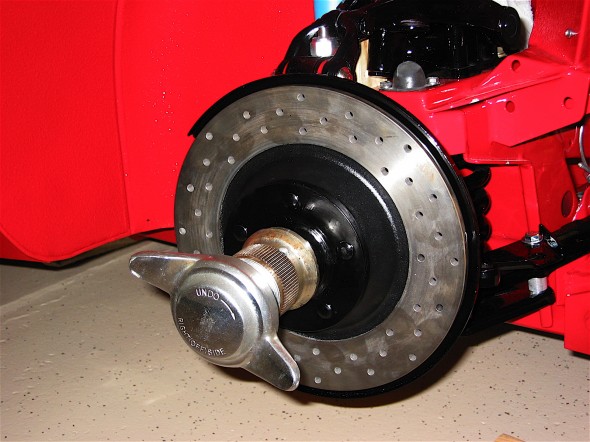
While standard rebuilt calipers were used in the front, the rotors were replaced with drilled rotors supplied by Cape International.
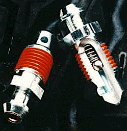
Speed Bleeders
I utilized the new technology for brake bleeders, Speed Bleeders. These bleeders have a small stainless ball in them that close off the release of brake fluid, making the process of brake bleeding much easier.
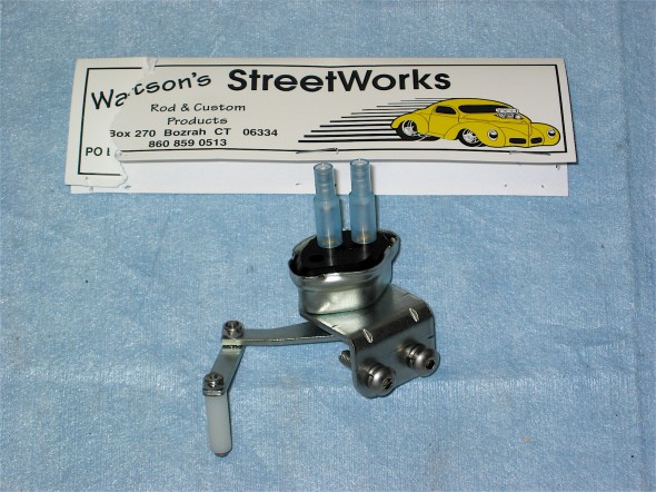
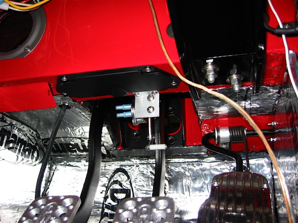
Recent production of the hydraulic brake switch has not produced a reliable switch. A remedy to the situation is to use a mechanical brake switch first developed by hot rodders. I sourced the switch I used from Watson’s Street Works. A description is provided in this Watsons mechanical brake switch.
Brake Reservoir Canister Gasket
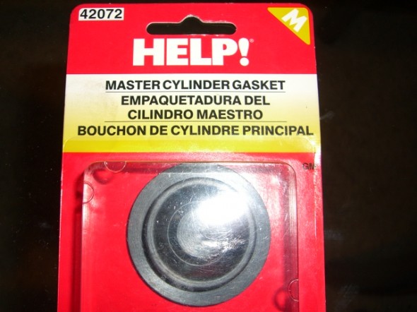
Other Healey restorers had noted that if overfilled, hydraulic fluid could slosh out of the vent hole in the reservoir cap and ruin the paint. Ever resourceful contributors to the British Car Forum discovered that a simple little gasket available in most auto parts stores fit perfectly in the reservoir cap, thereby solving the problem. I used one of the se “HELP” gaskets, #42072 in the Bloody Beast.
zz
Gas Strut Installation
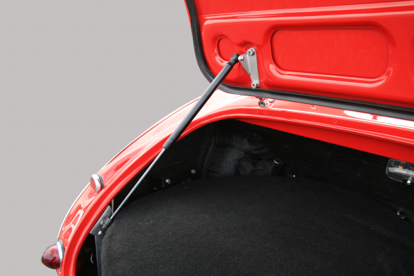
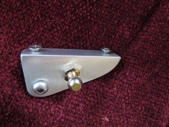
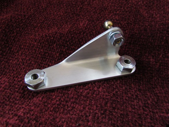
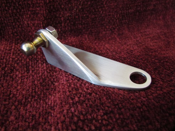
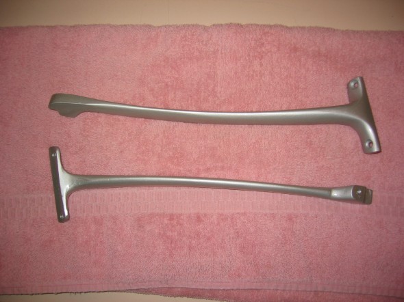
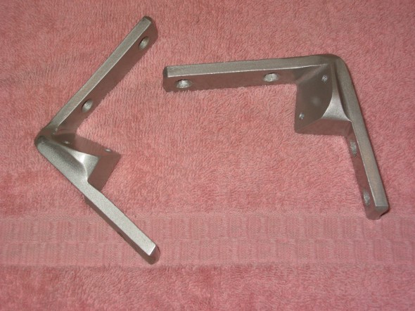
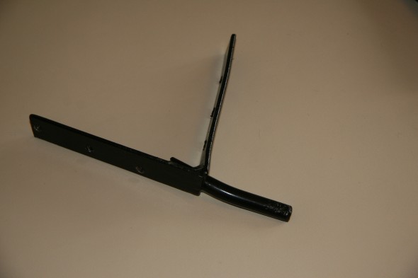
My friend Steve Thomton has an on-line gas strut business. So, it was only natural that he should come up with the bracketing and appropriate strut to install a strut in the boot of a Healey. As always, Steve’s work is of the highest quality. The components in Steve’s kit are remarkably well made. At the time I am writing this, he sells his kit for $129.00 which I consider a bargain. The kit consists of four primary components: the boot lid bracket, the shroud bracket, the shroud brace, and the strut with appropriate mounting hardware. Steve furnished excellent written instructions making the installation straight forward. Everything was in place and operational in under an hour.
I love this additional “personalization” of The Bloody Beast and would recommend it to everyone. It is so much more convenient than the folding rod as originally supplied.
This is a link to the instruction pdf: Trunk Gas Strut Install Instructions
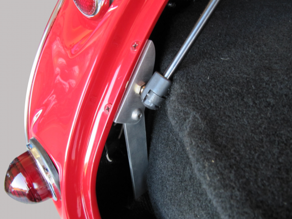
These are the brackets fabricated by Steve:
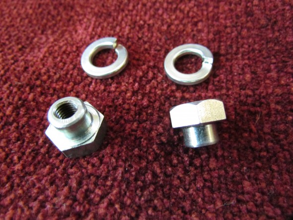
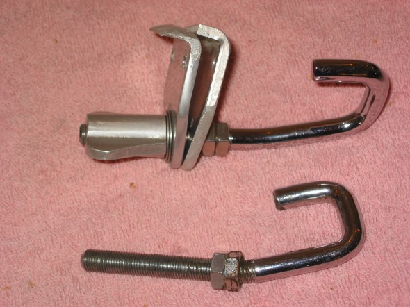
These are the collar nuts and split washers used at the boot lid bracket:
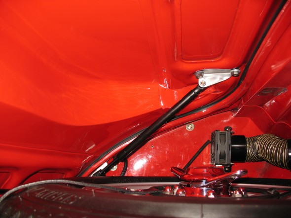
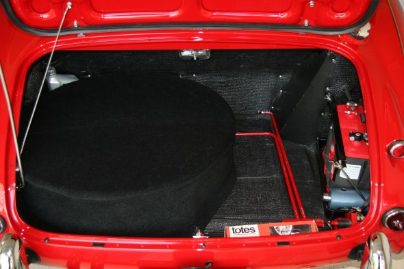
These are installation images (the last one in Steve’s car ( I didn’t have the creativity to take a delayed shutter shot in the boot with the lid closed!)
Spare Tire Cover
Assorted Body Modifications
Original Body and Brightwork
Numerous color combinations were available http://www.austinhealey.com/big.html. Bodies and frames were painted by Jensen. My BT7 L4422 was prepared in a lacquer Colorado Red with black coves.
Front and rear (tonneau assembly) shrouds were made of aluminum alloy, while the wings, doors, bonnet and boot lid were fabricated in steel. These components often did not fit well together requiring adjustments by the assemblers on the line.
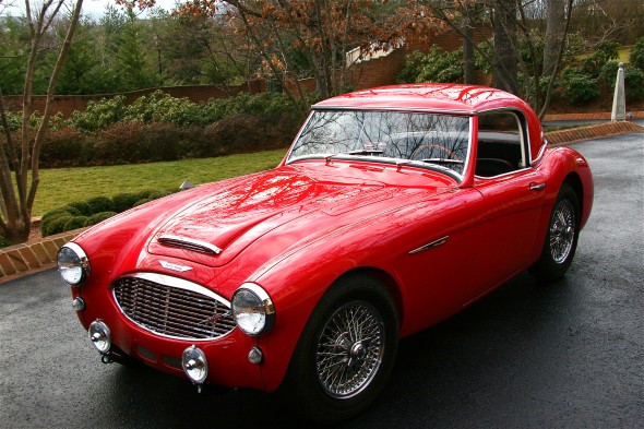
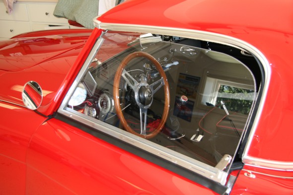
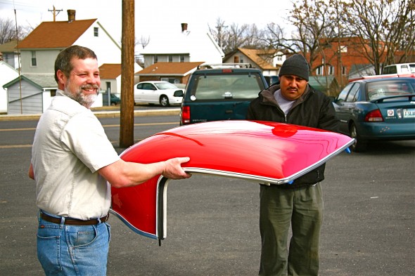
Roadsters had removable side screens with perspex panels. The black soft top was supplemented by an optional fiberglass hardtop also in Colorado Red.
Body and Brightwork Modifications
Paint
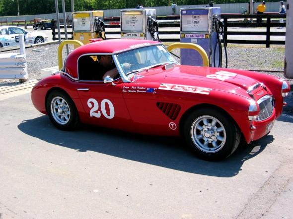
When I began visualizing my restoration project, I thought that I would keep my car Colorado Red; however, my thinking was changed in 2005. I attended the USA-Aussie Challenge at Summit Point Race Track and spotted the beautiful Paul Freestone 100-6, prepared by the Healey Factory in Australia. An email to the Healey Factory and in a day I discovered that the Freestone car was painted 1997 Ferrari Rosso Corsa (racing red). Seeing the Freestone car also helped me decide that I would be painting my hardtop the same color.
Alloy Wings
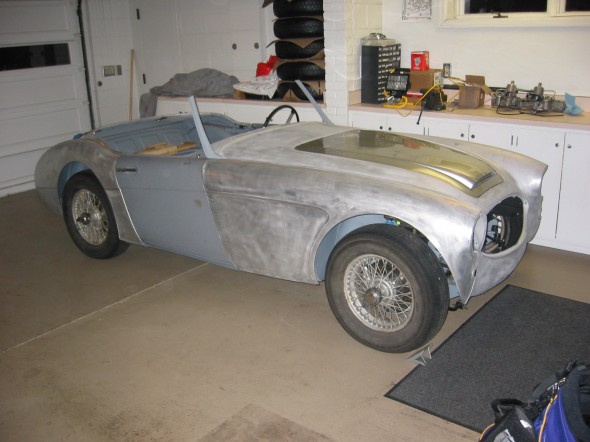
Now that the restoration of the Bloody Beast is complete, and having the knowledge gained from the process, I would have repaired the fairly extensive rust on my original steel wings rather than installing the new all aluminum wings that were sourced from AH Spares http://www.ahspares.co.uk/. Jeremy Turner, my body man, invested many hours getting the wings to fit properly. However, the good news is that they will no longer rust and the alloy wings are very light.
Carburetter Access Panel
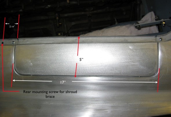
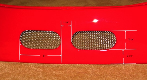
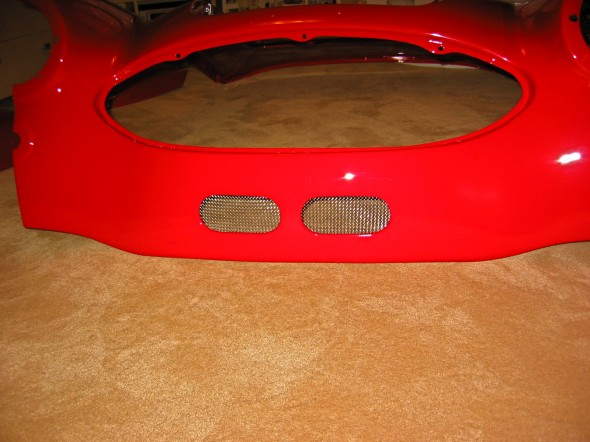
The Healeys prepared for racing and rallying often had carb access panels cut into the bodywork. I liked the idea of doing something similar although not so much to access the carbs, but more to access the master cylinders. I recall standing on my head while in college trying to change out the seals in the brake master cylinder – not easy to get to! Craig Naff, a master body craftsman designed and built my access panel and I have to admit that while biased, I have seen none better! The image below shows the panel with its dimensions before the car was painted.
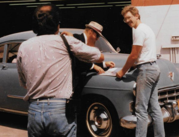
Editor’s Note, May 2020: I had no idea at the time, but I have since learned that Mr. Naff who did the carb access panel and oil cooler vents on my car is quite the celebrity. When Jeremy Turner and I visited his shop in little Woodstock, VA I noticed that he had some very nice cars under restoration and that his shop was well appointed from a tools perspective. I read the following in the New York Times about a fellow who had Craig do work on his hot rod:
“Getting that “guy,” Craig Naff, to work on your car is the customizer’s equivalent of commissioning Rembrandt to do your family portrait. Mr. Naff is one of a handful of sheet metal artists in this country who can create a complete car body from flat steel sheets, according to Ken Gross, an author and curator of museum exhibitions around the country.
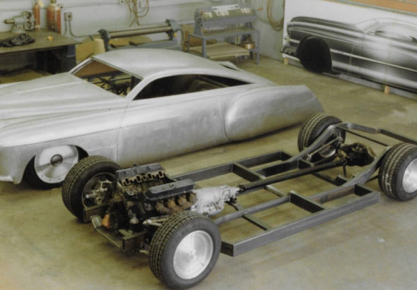
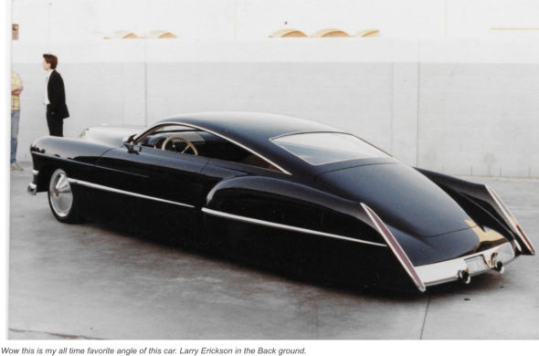
Mr. Naff, who works alone in his Shenandoah Valley shop, spent a stretch of his early career in California, where he sculpted body panels for CadZZilla, the landmark custom 1948 Cadillac that Boyd Coddington produced for Billy Gibbons, the ZZ Top guitarist. That car is widely agreed to have set a new standard for custom car design when it was finished in 1989.
Cars that Mr. Naff has either modified or created entirely have won the America’s Most Beautiful Roadster award at the Grand National Roadster Show, now held in Pomona, Calif., hot rodding’s equivalent of Best in Show at the Pebble Beach Concours d’Élégance. Mr. Wuchiski had to wait 18 months before the work could start, then another 18 months before it was done.”
Here are a few before and after images of CadZZilla:
Oil Cooler Vents
I have not felt the need to install an oil cooler, but I thought while the body prep work was being done, it was time to install the vents. I like the look even if they are not actually needed to direct air to an oil cooler! I looked at many different cars with vents installed. I discovered the size of the vents and their placement on the shroud varied substantially. I finally took measurements from an original rally prepared car and used them as direction for my car. Again, Craig Naff executed the plan perfectly.
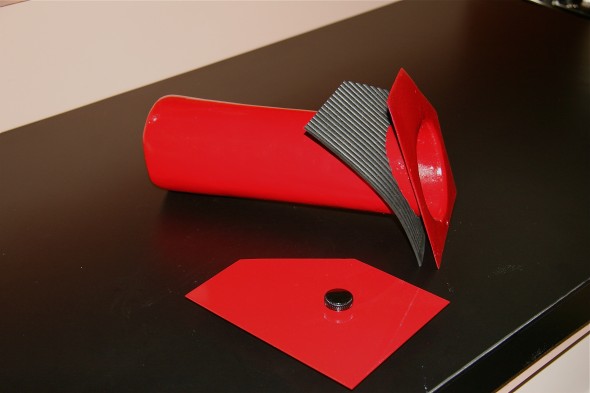
Tracy Drummond. recognizing that storage is always an issue in a Healey, came up with a way of utilizing a space under the bonnet for storage of small items. He made a tube of fiberglass and installed it in the lightening hole on the RH firewall/frame brace. So, “thank you,” Tracy, I copied your design although I think you used a tobacco can as a mold while I used a cylindrical Glenfiddich package for my mold! Here is the product of my work:
License Plate Bracket
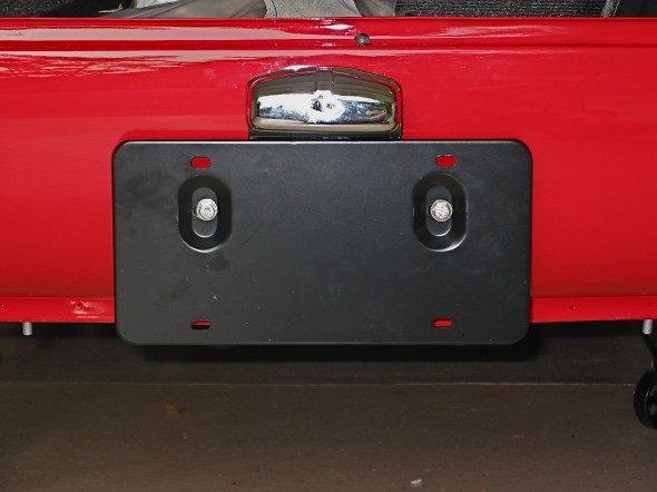
I have chosen to forgo the stock bumpers on the Bloody Beast, but since the license plate was fixed to the rear bumper on the MKI, I had to come up with another configuration. I tried numerous options until I came up with one that satisfied me. The final product was actually a combination of the roadster bracket and the later BJ8 bracket.
Post-mounted Driving Mirrors
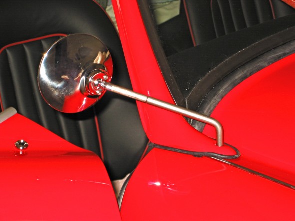
The Bloody Beast had wing mounted mirrors when I purchased it in 1971. They were impossible to adjust from the driver’s seat. On my rebuild I knew that I did not want to drill holes in the wings or shroud for mirrors and I knew that I wanted mirrors that I could easily adjust. Cape International http://www.cape-international.com/ sold a mirror that mounted using the front-most mounting screw for the windscreen post that fit the bill. The passenger side mirror has an extension that must be used to make it visible from the driver’s seat.
Tow Hook/Driving Light Brackets
In addition to the functionality of improved lighting for driving, I always liked the looks of driving/fog lamps on the Big Healey. I had planned to fabricate my own brackets for the lamps, but then came upon these dual purpose brackets sourced from Cape International http://www.cape-international.com/. While I am pleased with the appearance, my experience has been that the metal stock used is not of sufficient grade for towing. From a central pull source on a trailer or flatbed tow truck, the eyelet brackets bent when stressed. They seem to be fine for tie down hooks (for which they are probably intended), but not so much for pulling the weight of the car. In my case I was able to bend the brackets to a correct position.
Rally Bumpers
I spotted Sprite Bugeye bumpers turned upside down mounted on a couple of Big Healeys at shows and noted that they were also used on Healey Rally cars. I liked the look, though they would hardly provide any real protection for the bodywork in the case of a rear end collision! Again, Cape International http://www.cape-international.com/made a kit with brackets and bumpers to mount on the Big Healey so I purchased a pair. As installed, they sit slightly too far from the body in my opinion and I may modify the brackets at a later date to adjust the positioning.
Luggage Rack
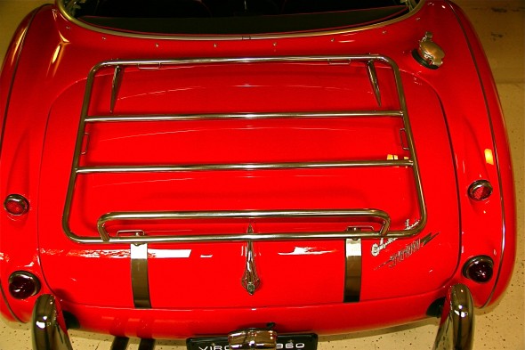
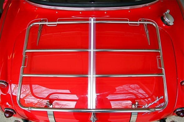
Knowing that I was planning on driving the Bloody Beast on long trips (as in an 8,000 mile cross-country drive) I planned from the beginning to install a luggage rack. After studying a number of variations available on the market I decided on the Cape International http://www.cape-international.com rack for a number of reasons. It sat close to the body rather than protruding up into the air providing for better visibility when loaded in addition to enhanced esthetics, it mounted without any holes being drilled into the car, and it was of sufficient width to carry a couple of small suitcases. The rack is made of stainless steel and is nicely done with welded strapping loops.
3M Ultrashield
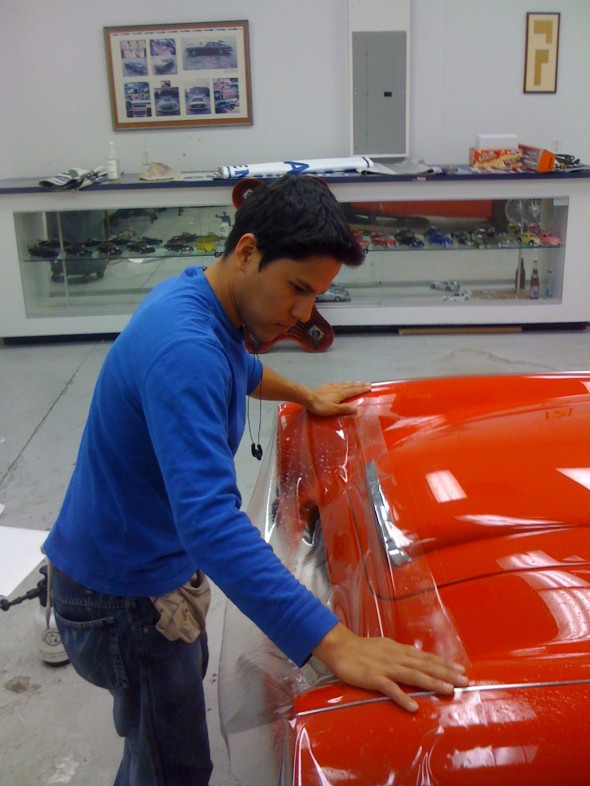
I chose to not use a front bumper and front valance making my front shroud paint particularly vulnerable to gravel and road debris so I opted to install 3M’s Ultrashield product. This clear protectant has provided excellent protection for the front of the car. In fact, I wish that I had installed it on selected frame members for chip protection as well. I took the car to Richmond, VA (about a two hour drive) to have the installation done.
Getting the Ultrashield film to fit all of the complex curves of the healey was no small task. Here is a short video showing how the application is done:
Side Curtains
March, 2009
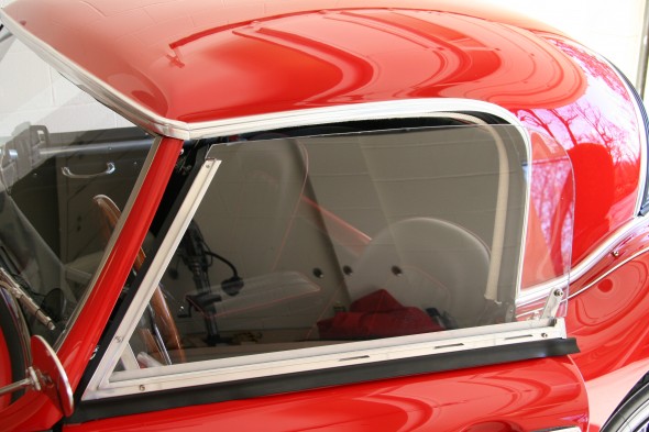
I currently have brand new sidecurtains. They fit reasonably well, have new clear plexiglass that slides easily and the new aluminum frames are blemish free. In other words they look about as good as side curtains can look.
However, with a 7,000 – 8,000 mile cross country trip ahead of me, I am looking for a way to modify the sidecurtains so that they will not be so noisy. Even though they are new, they still rattle like crazy. The two plexiglass panels bang together and make a real racket.
Tim Moran and I have been working independently on a modification or redesign of the side curtains to address a couple of issues, but in my case primarily the noise.
I decided to use an old set of aluminum side curtain frames as the basis of my project. I cut the top and rear upright out of the frames so that I could slide a new piece of Lexan (one piece) into the frame. The inside track of the frame is wide enough to accept the 1/4″ Lexan. I suppose that I could spend some big bucks and have a fabricator make a chromed brass channel for a frame, but I didn’t have time before my trip. The other reason for modifying the original frame is that it allowed me to just insert new rubber seals to seal the side curtain to the exterior of the door. I used Lexan because it is much stronger than plexiglass, and it can be drilled without fear of cracking.
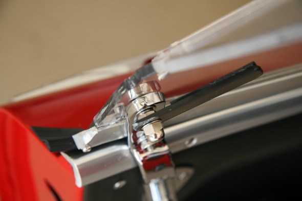
I also used the two original brackets that mount the side curtains to the inside of the door. For the rear bracket (as the photo shows) I inserted the bolt for the top fitting of the bracket through a hole I drilled in the Lexan. I then made a pattern for new glass and had a glass shop cut my Lexan. I am pretty satisfied with the one-piece side curtain glass. Of course, the big problem is no ventilation.
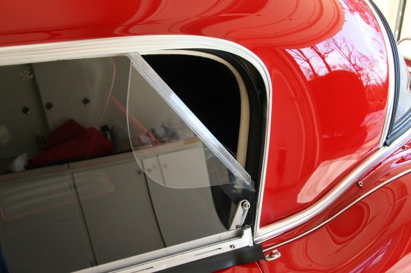
So I made an additional Lexan panel with a hinged section so that I could let in some fresh air and pay the tolls at the toll booths. I got my idea for this from Tim although our concepts are bit different. I used an acrylic hinge from McMaster-Carr. http://www.mcmaster.com/#11565a12/=1dshceThe acrylic hinge is not as flexible as the polyester that McMaster-Carr offers, but it is completely clear.
I took the car for a ride with the new glass and I can only imagine that it must be very similar to a BJ7-8 now. Absolutely no rattling or wind buffeting and actually very little wind noise – quite comfortable.
To hold down the flap, you can see in the photos that I made a little metal tab from 12 gauge steel, 3/4″ wide. I rounded the corners and glued a piece of rubber to it so there is a buffer between the lexan and the metal. When the flap is in the upright position, you cannot see the metal tab as it is hidden behind the side curtain rear bracket. When the flap is down you just rotate the metal tab upward to hold the lexan flap.
I gave the hinged lexan panel with flap a road test also. Like the one piece lexan windows, the one with the fold down flap also functioned quite well. A little fresh air and no rattling. The air intake is limited. A larger flap would bring in more air I am sure. It is all a matter of personal taste.
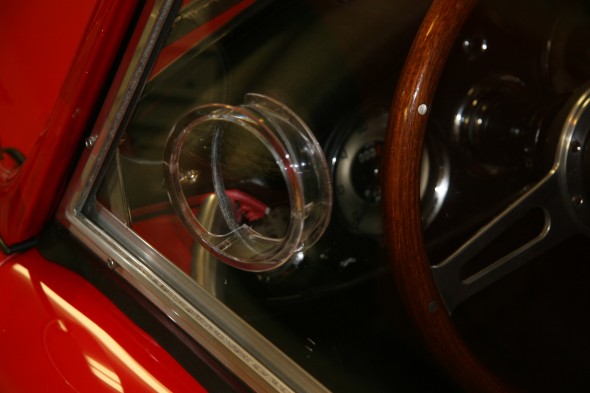
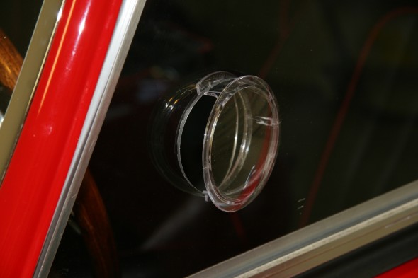
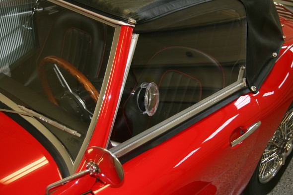
In my continuing quest to improve on the design and therefore functionality of the side curtains I have recently experimented with aviation vents. I saw this idea on a Cobra Forum posting and thought I would give it a try. The vents are made of clear acrylic and cost all of $15.00 a pair. I ordered them from Aircraft Spruce http://www.aircraftspruce.com Snap Vents, #05-01179, $14.85/pair.
Installation is literally a “snap.” I located where I wanted to the vent to be (avoid interference with wing driving mirror), and then drilled a 3 1/4” hole in the Lexan. Smooth the edges with a file and/or sandpaper and then compress the sides of the vent a bit and snap it in place. That is all there is to it. I like this option and plan to use it as my final solution (until I think of an improvement, of course!).
zz
Overnight Travel Cover
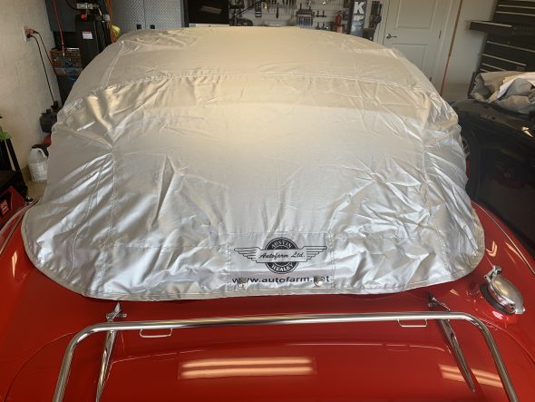
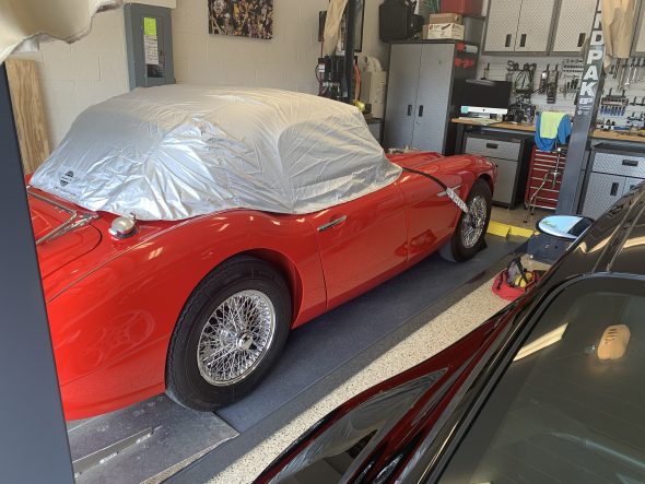
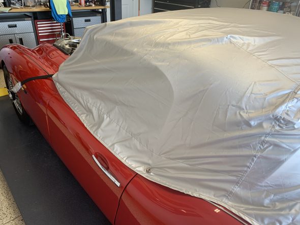
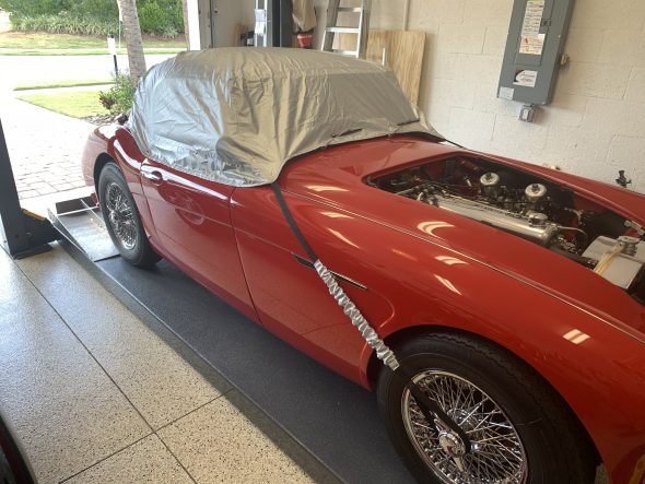
Having attended many multi-day car shows such as Conclaves and Encounters, I have seen travel covers that cover just the top of the car and offer interior protection from the elements, but don’t cover the full body of the car. The beauty of these is that they are light and easy to manage when traveling. I saw one on the Autofarm website and after all of these years decided to go ahead and purchase one.
I am very pleased with the quality of the product. It is extremely light and folds up into a nice storage bag. One has to install two lift-dot mounting fasteners at the rear and the turnbuckle fittings at front of the rear wings and that is it.
Luggage Rack Lexan Boot Lid Shield
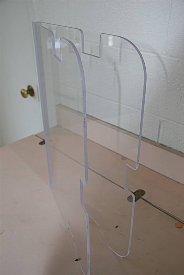
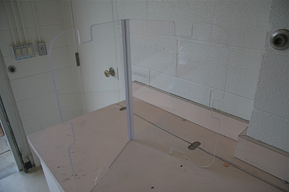
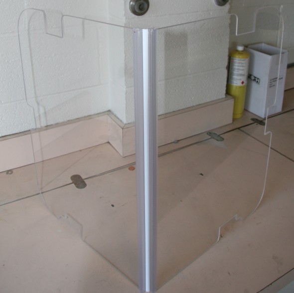
I have a Cape International luggage rack on “The Bloody Beast” and I am very pleased with its looks and functionality. One of the features I like best is how closely the rack “hugs” the contours of the boot lid; however, the curvature of the boot lid makes it quite possible for items carried on the rack to rub against the paint with the possibility of ensuing paint damage. This is especially true if you desire to carry something like folding chairs in bags that are not completely flat. To protect the paint I developed the folding transparent (and waterproof) plexiglass shield shown below. The folding joint in the Lexan allows me to fold the glass in half for easy stowage in the boot when not in use.
The hinge folds 180 degrees. Ordered from McMaster-Carr, 11565A11, Clear Acrylic w/White Polyester Middle. Lexan is 1/4” thickness and is quite rigid.
Hardtop
Introduction
I took my Universal Laminations hardtop apart in 1977 and, of course, intended to completely restore it to original standard at the time. This did not happen and it sat disassembled until I began to undertake the complete restoration of my car in 2001. We all know that it is best to take things apart, document the process, photograph the components, and reassemble as soon as possible. C’est la vie!
While I did not have the benefit of disassembly notes and photos, I did have the article published by Roger Moment Healey Hardtop Repair comp in the Healey Chatter in June 1998, page 22-35, Bill Bolton’s kit instructions comp (I believe from Moss Motors, Inc, 1994?) that were provided with his hardtop restoration kit, and some very helpful notes and photos from John Homonek who restored his hardtop to a beautiful standard. These documents and images provided helpful guidance as I progressed through my hardtop assembly. Click Restoring a Healey hardtop for a pdf file of this web site.
I would have to say that restoring the hardtop was one of my least favorite tasks in my restoration of the Bloody Beast. Until you get the top together it really is a very delicate job. This summary has sixty-eight photos, all of which are good size, as I have intended this write-up to benefit others undertaking this job. I hope it proves helpful!
Conditioning the Parts for Assembly
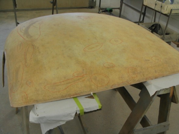
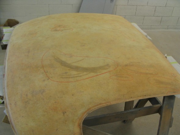
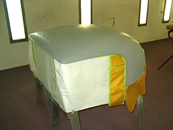
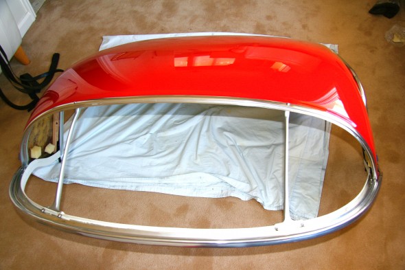
The fiberglass shell is very flimsy without the supporting aluminum hardware that serves as an external skeleton for the top. It had developed some cracks and blemishes over the years. These were patched first:
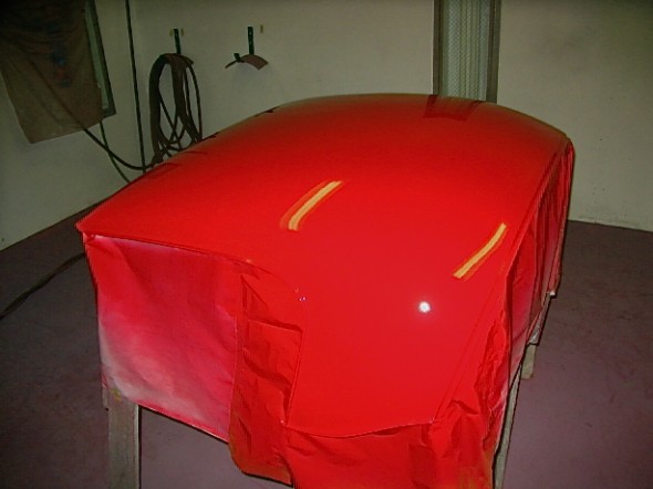
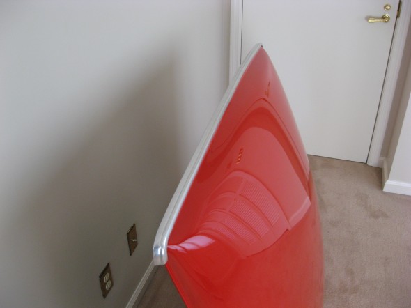
Followed by the application of Rosso Corsa Ferrari paint, and more sanding and polishing:
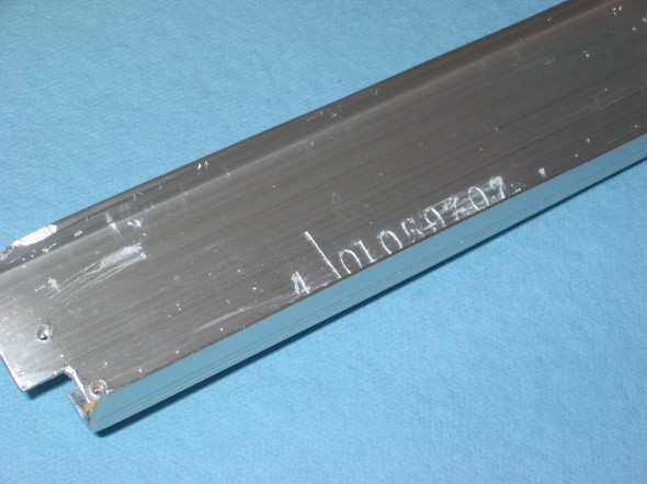
I cleaned up the aluminum frameworkas best I could including removing as much of the original clay/caulk/sealer that was possible from the mounting channels of the trim. The identification number for the hardtop and the assembly date is available on the right window cant rail.
I then sent the aluminum off to Ano-brite ( I believe it is now named something else) in California for further cleaning and anodizing. Everything came back sparkling and looking almost new. In the meantime, I ordered Bill Bolton’s restoration kit that includes, headliner and trim fabric, rubber seals, foam pads, windlace, a new rear backlight and instructions. All high quality! Thanks, Bill.
Cleaning up and refinishing several of the hardtop components was next on my list. The vertical rear aluminum braces and the front corner brackets were sanded and painted a dull aluminum that closely matched the original color.
The rear mounting hook/plate/wing nut assembly was also in good shape but I did decide to replace the hooks and again sourced them from Cape International. I ordered new mounting plates, but like the shape of the originals so I will stick with them.
The steel locating spigots just needed some cleaning up and painting. They were painted black and new truss head stainless screws were purchased for assembly.
The headliner was torn and dirty and needed to be replaced. The headliner frame needed attention, too. It was a little rusty and the felt was in bad shape. The frame was painted black and new felt was glued in place.
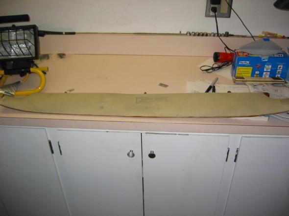
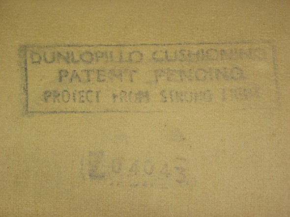
I was surprised to find the foam of the front pad in excellent condition after removing the headliner fabric. I don’t know Italian, but it appears that the Dunlop foam rubber was manufactured (or at least the pad was) in Italy.
Hardtop Assembly
After getting all components in good shape or purchasing new bits, it was time to begin assembly. The first task was to glue the fabric to the bottom cant rail.
The I glued the fabric to the inside corners of the top shell.
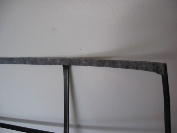
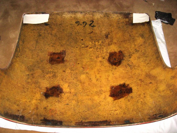
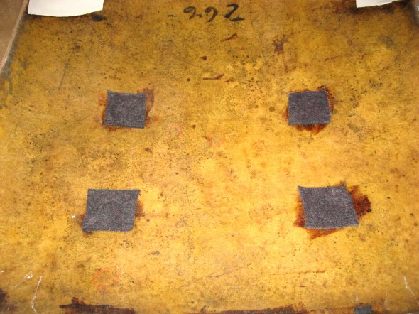
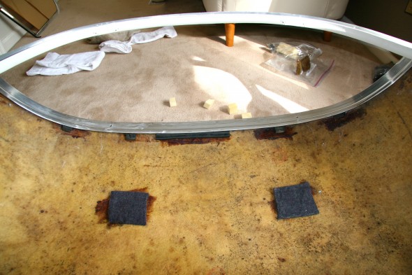
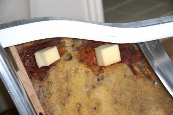
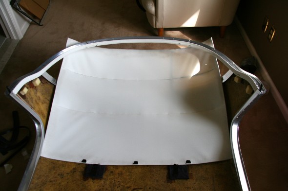
Followed by glueing the carpet felt to four locations on the underside of the hardtop shell. This buffers the headliner metal frame from the fiberglass shell.
Then applied 3M Body caulk (dum-dum) to the channel in the front rail and pushed it onto the front lip of top shell.
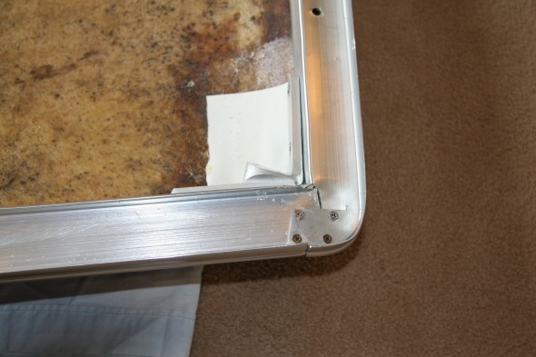
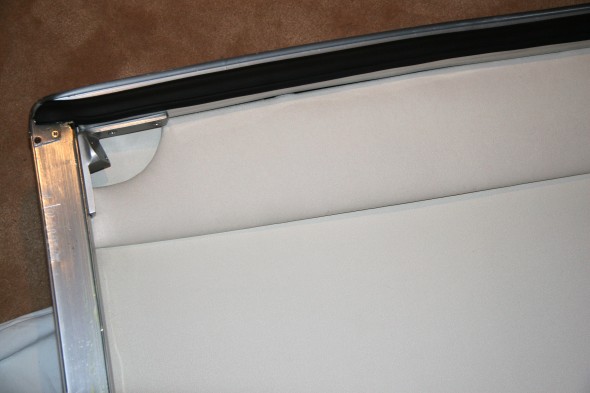
Applied 3M caulk to the channels of the side cant rails and pushed the rails onto the top shell. Temporarily screwing in the corner braces and the small aluminum plates helped pull the side rails into place.
The original wood braces that mount on the side cant rails were rotten. I had new braces made to original specifications. These were screwed to the side rails with two truss head stainless screws.
With the top upside down, the locating spigot pins were dropped into place, but not secured until after the bottom cant rail was pushed onto the top shell.
Applied 3M caulk to the channels in the bottom cant rail and positioned the rail on the top shell. This job requires two people! After properly aligning the rail, six stainless truss head screws can be screwed into place through the side and bottom cant rails into the steel spigot pin.
Applied a thin coating of the 3M caulk to the channel in the aluminum trim for the top of the backlight and pressed it onto the top shell. Again, two people really help with this task.
I then used a block of wood on each side of the top to spread the top toward the outside of the bottom cant rail and inserted two #10 stainless truss head machine screws with washers and nuts to link the bottom cant rail to the backlight top aluminum trim. After tightening the fasteners the wood spacer blocks were removed.
I had saved the five small original rubber seal pieces that were used as spacers/cushions between the headliner and the upper backlight aluminum trim. These were glued in place at the same locations on the inside of the top shell.
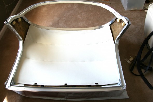
Bill Bolton’s kit included 4 small blocks of foam padding (two on each side) that I glued to the interior sides of the top shell. These pads are used to force the upholstered quarter panels against the side and bottom cant rails. The original part number for theses pads is 27H9592. Again, I could see where these pads were glued to the shell originally and they were cemented to the same locations.
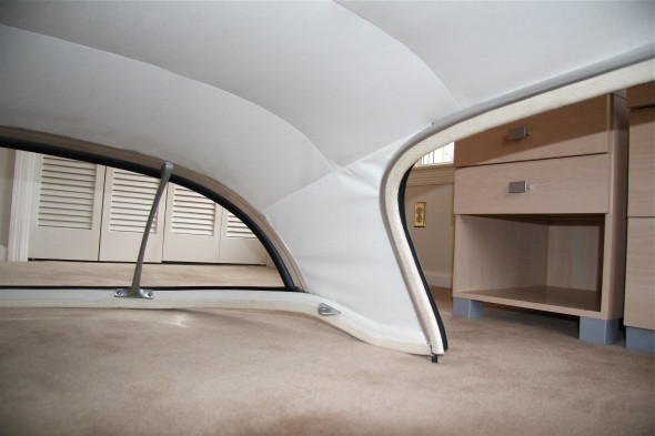
The headliner frame with new fabric supplied by Bill Bolton and sewn to the frame by a local shop, Classic Upholstery, was then inserted through the backlight opening and pushed into place. The metal clips at the front of the headliner were pushed under the front aluminum rail, and the rear edge of the headliner was pushed in place between the backlight upper aluminum trim and the rubber cushions that had been glued to the the shell.
The aluminum backlight braces were then installed. I stuck 3M body caulk under the heads of the two chrome machine screws that went through the backlight upper aluminum trim and into the braces to help seal out water.
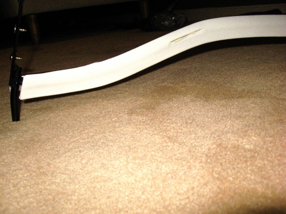
I was then able to flip the top over and install the front pad. The screws that fasten the front side braces needed to be withdrawn so that the triangular clip on the side of the front pad could be pushed into place between the two screw locations. The screws were then replaced. The front rail header seal, part number 27H9597, was then cut to fit and glued onto the rear edge of the front aluminum rail.
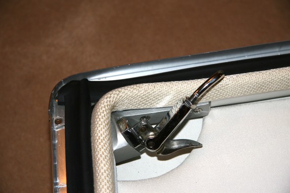
The rubber seals for the side rails were also trimmed and lightly glued in place. The windlace supplied by Bill Bolton was then pushed over the rubber seals and onto the side and front cant rail lips to create a nice finished look. One continuous piece of windlace was used to cover the rails. It is somewhat difficult to push it into place in the 90 degree corners. The front clasps were then screwed into the front corner brackets. I have these set as they were originally, but I expect the “J” hooks will need some adjustment when the top is put in place.
The hold down brackets that, along with large “J” hooks, clamp the hardtop to the cockpit were then inserted through the slots in the bottom cant rail and secured with two #10 truss head machine screws. I used the original quarter panel boards and recovered them with the headliner material. They were pushed into place and wrinkles were “massaged” out as much as possible.
Plexiglass Backlight Installation
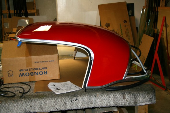
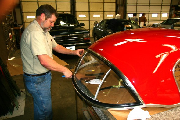
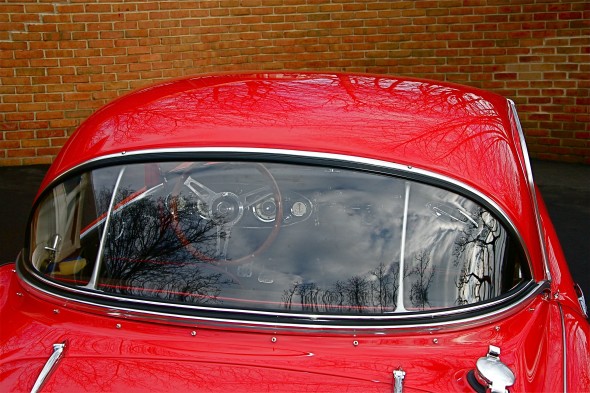
I may have been able to install the backlight myself, but after studying it a while, I decided to take the job to a local glass installation shop that had previously assembled my windscreen. I was glad that I did, because the plexiglass needed trimming to fit and the shop got the job done much more quickly than I would have fumbling along in my trial-and-error manner. The images below might help others who decide to undertake the task themselves.
I managed to get the top to the glass shop without damaging it! The owner reviewed the plexiglass, the seals and proclaimed himself ready for the task.
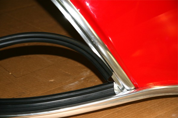
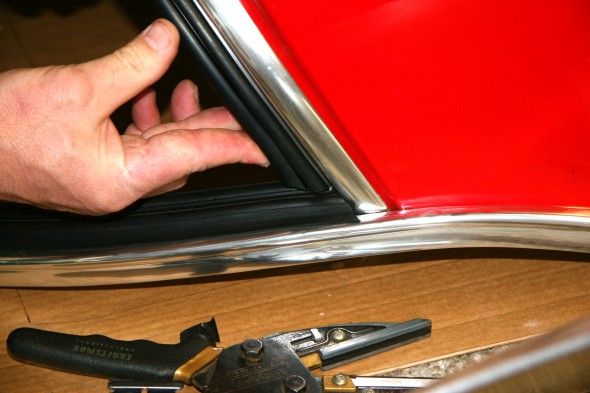
To get a feel for how the top and bottom seals would ultimately join together the installer slid the pieces together on the rails. The upper backlight glazing rubber was part number 27H9594. The lower glazing seal was part number 27H9595.
The iterative process of trimming both pieces began until he was eventually satisfied that the fit was as good as it was going to be. Of course, the second side, in this case the LH side was more difficult to fit. The key is to trim only a little at a time. You can always trim more, but if you go to far there is no recovering!
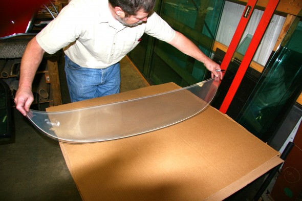
The installer used a silicon spray to temporarily soften and lubricate the rubber to make it easier to fit the plexiglass and the locking seal. Unfortunately, we discovered that my glass was not shaped properly.
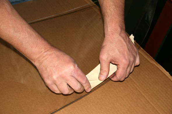
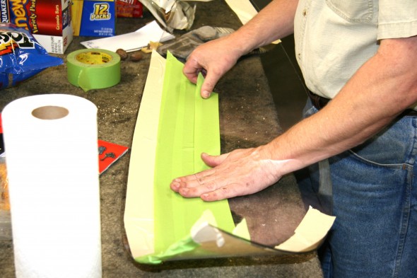
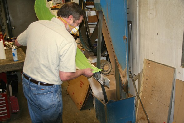
I was able to compare it to my “foggy” original and one could see that trimming was required. As with the rubber, the rule was “a little at a time.” We taped the glass to mark the material to be removed and to avoid scratching it and then used a belt sander to gradually remove material. We repeated this process three times until satisfied with the fit.
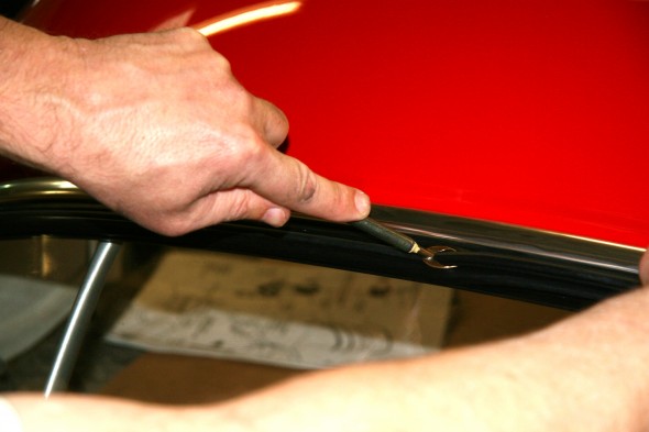
We experienced a little problem with the lower locking strip – it just did not want to “lock” on the bottom edge of the strip. The shop had another, slightly larger, strip that worked, but it had a chrome finish. I will paint the chrome a matte black to look just like the rubber. The plastic tool in John’s hand is known as a “bone.”
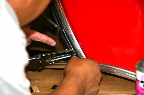
These are a few images of the locking strip being “run in” to the larger seal. As always, the right tool for the job is key. John’s assistant trimmed the locking strip to the proper length.
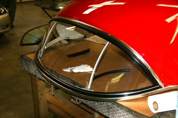
After installing the locking strips and cleaning up the silicone spray residue, the backlight installation was complete. Now, it is back home to put the seals on the bottom cant rail.
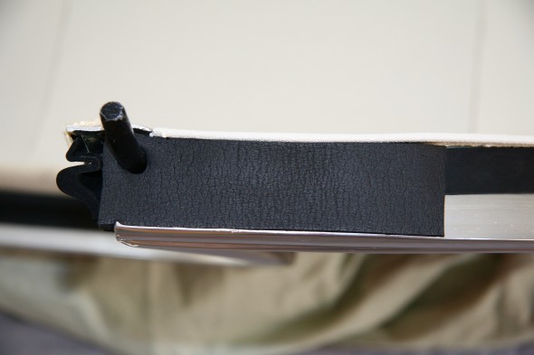
I believe the original spigot pin pad was 5” x 1/2” x 1 1/8” (27H9599). I did not have a replacement pad that met original specs, but I used 2 pieces of weatherstripping on each side that were 5” x 1/4” x 1 1/4”. These pads were punched for the spigot pin and then glued together to make a pad similar to the original.
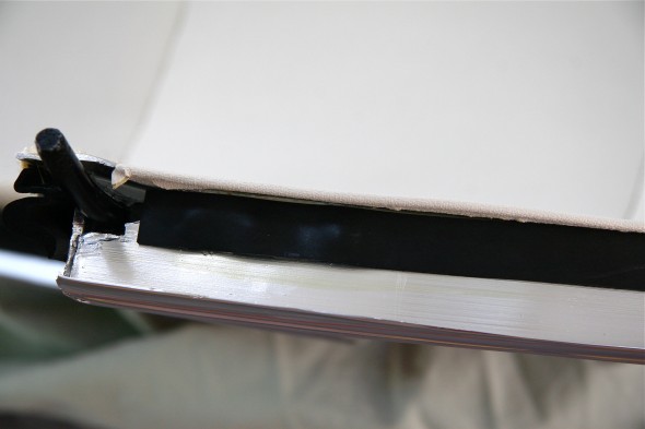
The narrow (3/4”) packing strip for the bottom cant rail (27H9686), was then glued into place. The piece in the image below was cut off to butt against the spigot pin pad.
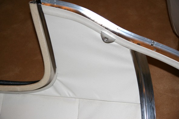
The wide (1 1/8”) packing strip, to the left in the image below, was glued over the narrow packing strip and it also was run to the back of the spigot pin pad. Then the header rail seal (27H9597) was lightly glued over the edge of the bottom rail and the windlace was pressed over it and the rail to give a finished appearance.
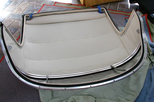
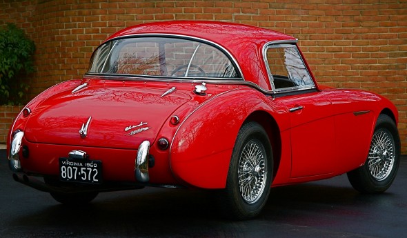
The finished job is seen in the images below. There were several things that could have been done a bit better, but isn’t that always the case with the first time you do something? I was generally pleased with the results.
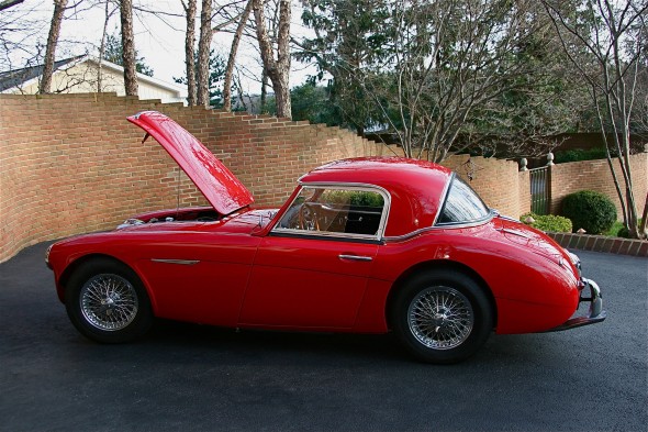
These are some images of the top on my car. It took some time to get the top to fit well with the cockpit molding. I still have a slightly larger gap at the top quarter panels than I want so I will continue to try to refine my fitting.
Storing The Hardtop
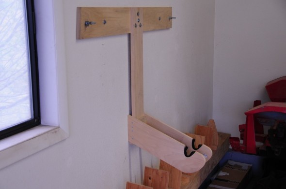
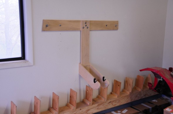
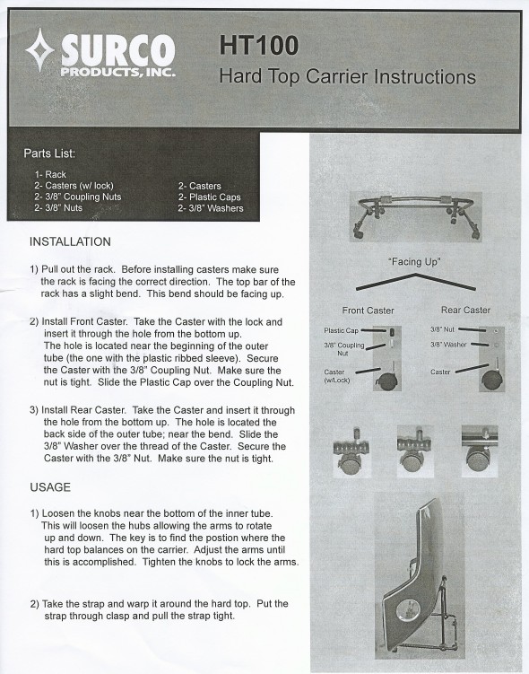
While I love my hardtop, Healeys were meant to be driven with the top down or off. That means storing the hardtop out of the way and where it will not be damaged. I am sorry that I don’t recall the source of these images, but they illustrate a homemade wall mount that would appear to be very effective. I may build this mount, but have not done so yet. I did order a cover and rolling stand for my hardtop from California Car Cover. Both are working quite well for the moment.
Hardtop Cover pdf:
http://www.calcarcover.com/product.aspx?id=1037
John Spaur at [email protected] built an overhead hoist for his top for about $50.00.
This is another hoist plan that was put together for Jeep Hardtops. It includes a list of materials needed:
http://www.jk-forum.com/forums/jk-write-ups-39/hardtop-hoist-storage-write-up-5559/
and a pdf file of the same:
Hardtop hoist:storage write-up
And, this is yet another overhead hoist that can be purchased for installation in one’s garage:
http://www.top-hoist.com/index.html
and a pdf file of the same:
Top-Hoist.com — manual and electric hoist lifts for your convertible hardtop
zz
The Beast’s First Drive
The Beast’s First Drive
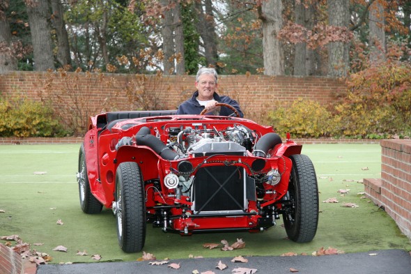
December 1, 2007 was the date of the first drive with The Bloody Beast. This first test drive was merely onto the tennis court and back to the garage, but it was an exciting achievement. Actually exhilarating would be a good word to describe the experience. After years of work, the end is within sight.
A click on the following link will direct you to photos of the first drive:
http://www.flickr.com/photos/valve-chatter/sets/72157630759109366/

