The Broken Axle Half-shaft

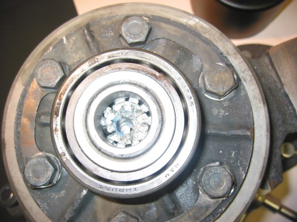
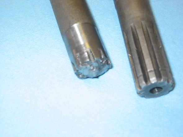
I was driving in the countryside near Dayton. Coming back into town I shifted to first gear to accelerate from a stop light only to find that while the motor was running like a sewing machine, the car would not move. The car was towed home. After initially expecting to find a problem with the clutch linkage or the transmission, we discovered the problem was a sheared axle on the driver’s side. Everyone tells you how easy this is to fix, but no one describes that it can be very difficult to get the inch long broken piece of half shaft out of the differential! We got a little help from Jack at Coachworks to remove the broken piece.

Axle in Differential

Axle in Differential

Sheared Half-shaft

Sheared Half-shaft

While under the car we also discovered that the rebound straps were about to go, so we replaced them at the same time.

Hardened steel competition axles were ordered from The Winner’s Circle. Expensive – $249 a piece! They should never break again. We decided to use Bill Perry’s (Rivergate) suggestion and applied Form-A-Gasket to the differential and to the axle hub faces rather than using paper. We will need to evaluate how the approach works. We also replaced the brake shoes because when the half shaft broke we discovered oil leaking from hub on the driver’s side.


Anti-sway Bar Installation

Anti-sway Bar

After waiting for quite a while for delivery of an anti-sway bar, we installed it with minimal effort.  We were somewhat disappointed that the links to the wishbone touched the inner side of wheel when turned to full lock. Called Tom Colby at Speedwell Racing that manufactured the bar to see if we had made an installation mistake. He said, “No, just don’t turn the wheels to full lock position!” Couldn’t believe it because Speedwell Engineering is a very reputable race car prep shop.

Installation instructions were provided by Speedwell. With everything clean, we did a careful visual inspection of the frame rails, anti roll bar mounting pads, and the lower control arms.  It is a very good idea to weld the frame rail seams and also weld completely the mounting pads, which are only partially welded by the factory.  It is very common to have the lower frame rails tear themselves apart from the heavy cornering forces.  With this done, we ran a 5/16 X 24 tap through the mounting pads to insure good clean threads to attach the anti roll bar to the frame.  We then installed the bar to the frame.

The bar may be mounted to the frame with the car raised in the air but the rest of the installation must be done within car at its ride height.  We slid the Delrin bushes onto the anti roll bar and then mounted the bar using the pillow blocks supplied.  We center the anti roll bar and locked down the shaft collars after it was centered.  The anti-roll bar should move somewhat freely in order for it to function properly.   We then installed a rod-end into one end of the anti-roll bar and attached a corresponding bracket.  Then, we swung the bracket up to the lower control arm and positioned it so that the link was vertical.  This is where the 3/8 inch bolt holes should be drilled and bolted to the A-arm.  Now we did the same to the other side.  With the driver in the car the links should be adjusted so that there is no pre-load on them.  Finally, we tightened everything and we were ready to go.

Engine Improvements

Gear Reduction Starter

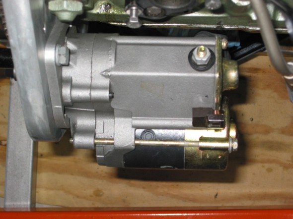
Replaced the starter with a modern gear reduction starter from APT Fast. Unlike the old Lucas starter it cranks until the motor fires. Definitely more difficult to install than the original, but hopefully easier starting will make it worth it. Fastening the lower bolt was accomplished by jacking up the right front, removing the tire and wheel and reaching through the hole in the frame wall. The cranking sound is very different than the Lucas starter, but functionality is substantially improved. We chose to continue to use the old pull starter switch on the dash, but could have hooked up the starter to a modern solenoid as well.

Gear Reduction Starter

Gear Reduction Starter

The 2001 Capital Area Classic

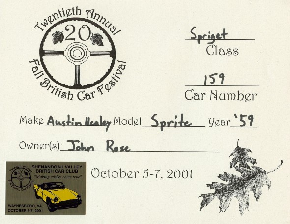
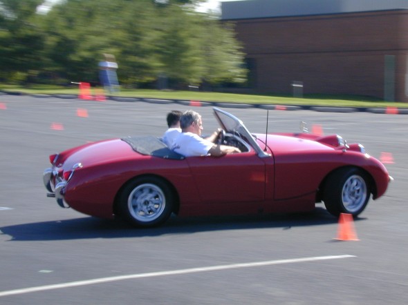
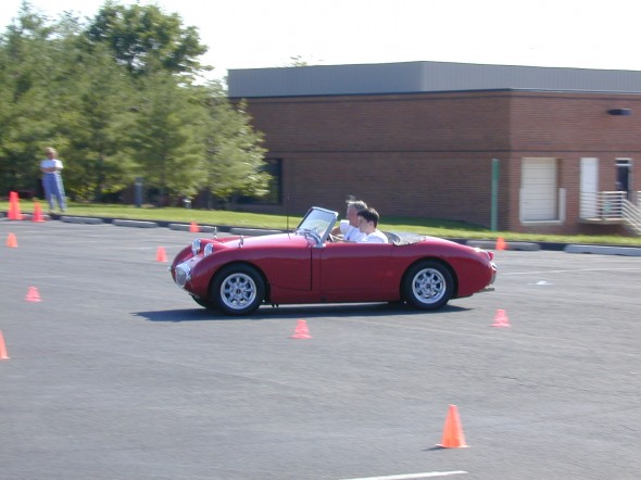
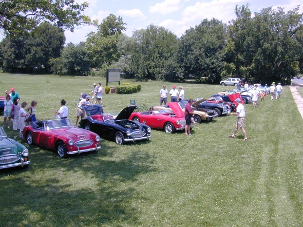
Dad and I attended the Capital Area Austin Healey Club father-son weekend meet at Frederick, MD. It was the first time that I had participated in a show or club event with my Bugeye, so it was pretty exciting. The car broke down in Berryville. After getting fuel it just wouldn’t start again. Turned out to be the starter, but substantial consternation involved before things got fixed by the next day. I participated in my first Funkhana and actually won it!

Just me, or are we leaning?

Just me, or are we leaning?

At Speed

At Speed

I came in second in the popular judging show. Highlight of the event was that Gary and Paulette Lownsdale, The President of the Austin Healey Club of America attended. I drove the Bugeye home from Frederick – about 2 hours.

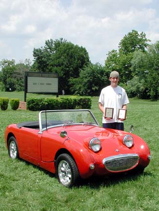
My First Awards!

My First Awards!


Popular Car Show, Frederick, MDPopular Car Show, Frederick, MD

This is a pdf file of the report of the event which was posted on the club’s website: Just click to see the four page write-up.

Capital Classic 2001


Engine Enhancements

crane ign. The car is running a little rich. I attempted to adjust which became an experience. As the book says, I backed off the jet adjusting nuts 11 flats only to find that the car would not start at all. After a little help from the midget/sprite email list, I backed off the jet nuts one flat at a time until I got to 24 flats before the car began to run well. However, now it runs better than ever.

Hayden Electric Fan

The car is running slightly hot (past normal temp) with just the hayden electric fan. Dad decided to put the 6 blade plastic fan on as well. The two together work effectively. Now we seem to be staying well within acceptable temperature range. I had tried to save the horsepower used by the water pump fan, but oh well.

Electronic Ignition

We installed a Crane XR-700 electronic ignition and had the timing, valve clearances checked by Jack Harper at Coach Works. This is the installation manual for the Crane Electronic Ignition: Crane XR700 Installation Instructions

Began installation of the electronic thermostat for the electric fan, but decided against it. Will just switch it on manually when needed. It’s a little noisy!

Making The Bugeye “My” Bugeye

Bolting on the new WheelsTires and wheels

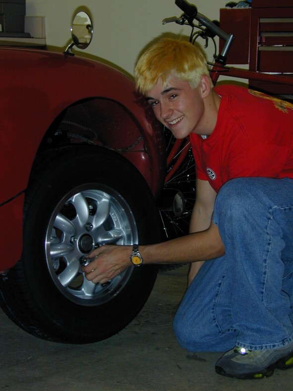
I ordered new Panasport 13 x 5″ wheels. I paid for the wheels and Dad paid for the tires – 185 x 13 70 Bridgestones. The tire selection turned out to be a mistake, they were too big and rubbed the bonnet when the wheel turned.

We ended up replacing the Bridgestones with Wynstar 185 x 13 60 lower profile tires which worked fine. Unbelievable difference in the handling for the car – it really sticks to the road now. Needed to order new lug nuts for the Panasport wheels as original equipment didn’t work with the wheels.

Hayden Electric Fan

Installed a 10″ electric fan to replace the plastic stock fan. Required fabricating some metal brackets to mount the fan, rather than using the plastic mounting screws provided with the fan. It’s better to have the fan pull rather than push air, but that won’t work with the bugeye because the fan won’t fit on the engine side of the radiator. Installed the fan with an on-off switch at the dash but will replace it with an automatic thermostat to control fan operation.

Intake Manifold

Located a used stock intake manifold. Installed it and eliminated the problem with the carbs hitting the bonnet when closed.

Conversion to Front Tilt Bonnet

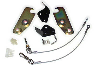
Purchased a front hinge kit from Minimania. Good kit that included complete instructions, hinges, cable restraints, brackets (although the cables were too short), and wiring. Removed original back body hinges, and latching mechanism at the front of the bonnet.Mini Mania FRONT- MOUNT HINGE KIT FOR BUGEYE SPRITE

Mini Mania Bonnet Tilt Kit

Mini Mania Bonnet Tilt Kit


  1. Clip headlight wire harness 16″ from passenger side blinker.
  2. Remove bonnet
  3. Remove telescopic bonnet catches
  4. Remove grill (13 retaining clips)
  5. Remove bonnet handle
  6. Remove two locating pins for bonnet
  7. Install support cable bonnet securing plates – 2 to bonnet installed by pop rivets and 2 on radiator mounting brackets
  8. Remove bonnet hinges – a long bolt and nut reached under the dash.
  9. Remove bonnet safety catch/latch
  10. Remove latch locator plate
  11. Install stainless steel bolts for new bonnet securing springs.

Mini Mania Bonnet Latch

 Mini Mania Catch Cable

Fabricated hold-down spring brackets using a conduit clip, spring and stainless steel bolts. This approach, copied from John Carey’s web site works great and is much less visible than rubber or leather straps on the side of the body. The front hinge set-up does not permit use of the front bumper. This assembly is made from a galvanized conduit wall clip slightly bent closed and attached to a zinc plated spring.  It is covered with a black plastic wiring harness cover so as not to be too obvious in the dark wheel well. The small stainless bolt is installed thru an existing hole in the bonnet (top of spring – left).

You must use nuts on both inner and outer sides of the bonnet to hold it firm in the position shown.  You can crank the wheels out of the way and quickly clasp the conduit clip under the floorpan lip (lower at left) then stretch the spring up until it grabs the head of the stainless bolt.  The position is perfect to hold the bonnet down and in against it’s intended rubber stops… This eliminates drilling to install and works great even in HEAVY cornering and bumping along back country roads.  It is also as quick or quicker than leather buckles to open and close.

Bonnet Catch

Bonnet Latch Spring


Conversion from Dynamo to Alternator

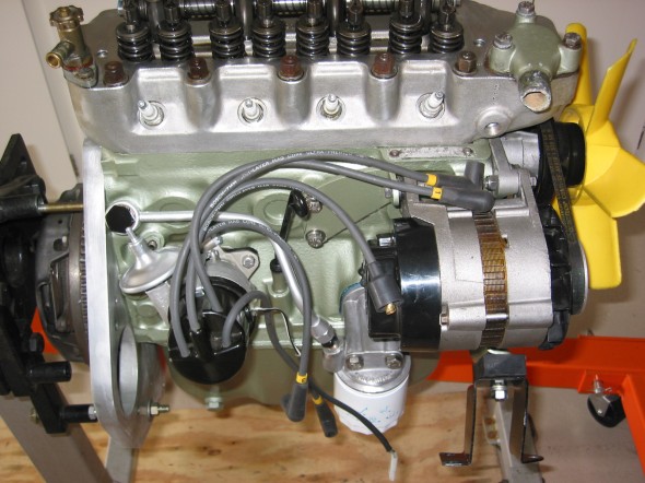
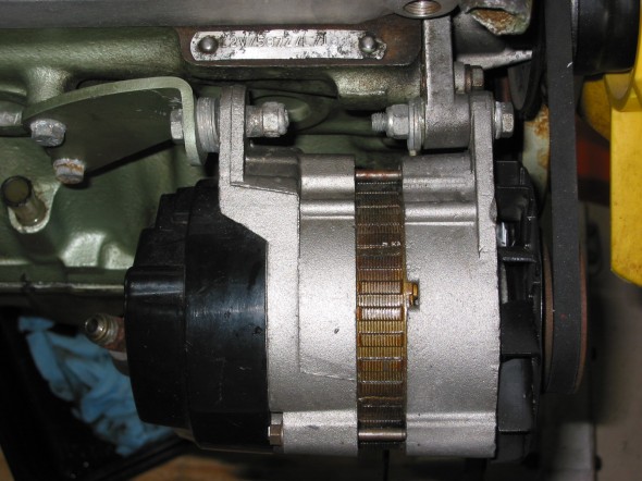
Removed the dynamo and installed a lucas alternator. Required reworking wiring and eliminated the need for the voltage control box. Referred to directions from Larry Miller and John Carey for wiring help. Seems to work well and should be a bonus if we ever add driving lights, halogens, radio and etc. A new fan belt was required for the alternator that is shorter than the belt used for the dynamo.

Removed and discarded large yellow wire from terminal D on the voltage regulator box to the dynamo. It is no longer needed.

Removed black ground wire from terminal E on the voltage regulator box to the dynamo. It is no longer needed.

Removed black wire from terminal F on the voltage regulator box to the dynamo. It is no longer needed.

Connect brown wire from alternator (middle spade) to battery post terminal.

Connect small yellow wire from speedometer warning light that originally went to terminal D on the voltage regulator box to the small spade on the alternator.

Connect large yellow wire from ignition switch that originally went to the A1 terminal on the voltage regulator box to the baby blue wire to the remaining large spade on the alternator, and to the purple wire from the fuse panel. These 3 wires are soldered together.

Collect wires and plug connector into the alternator.

Alternator Wiring Diagram

Alternator 2

Alternator 2

alternator

alternator


Installing the 1275 Motor


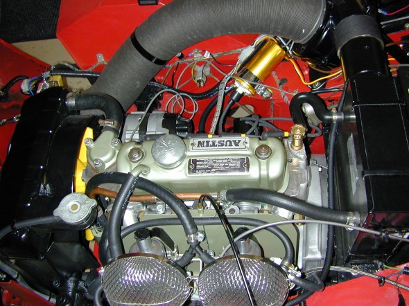
The engine and gearbox were purchased from Rivergate Restorations. After driving the Bugeye on the Washington Beltway to bring it home the first day, Dad and I knew that we would have to get some additional horsepower in the Sprite. The Rivergate  setup was just perfect. We were very pleased with the product and the service.

The engine numbers 12V/587Z/L7183. This engine was sourced from either an Austin-Healey Sprite, MK4 or from an MG Midget, MK3. The 587 engine was produced for North American Sales and was apparently rather rare in the States, so it may have been a Canadian car. The “L” stands for low compression, that is 8.0:1. The engine was produced  from 8/1971 to 8/1972. The engine, as produced at the time, would have been painted black.

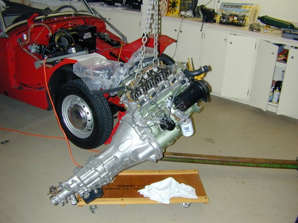
Installed engine and transmission. Reverse of removal process. Unfortunately we got the engine mounts reversed and backwards which resulted in a great deal of frustration in seating the engine. Finally with a little outside help we corrected the problem and the engine went in like a charm. It did require a little beating with a hammer on the plate below the heater box so that the transmission would clear. Of course, the header and carbs had to come off the engine before placement in the engine bay.
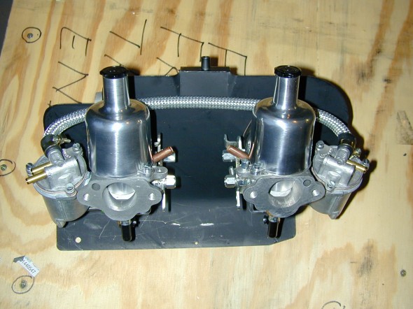
New 1/2" SUs

New 1/2″ SUs

Motor Ready to Install

Motor Ready to Install

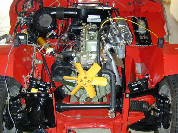
New 1275 In Place from Rivergate

New 1275 In Place from Rivergate

Bill Perry, from Rivergate, provided installation instructions that proved to be helpful. Rivergate Engine Installation Instructions 2000

Rivergate also provides a comprehensive instruction manual for the installation of the Datsun B210 5 speed transmission. Because we purchased the transmission and installation kit with the transmission already mounted to a rebuilt MG Midget engine that we also purchased from Rivergate, much of what is described in the kit installation manual was already done by Bill and/or Will Perry. The annotations in the margins of the instruction manual indicate the previously accomplished work. Rivergate Installation Instructions 5 speed Transmission Conversion Kit 1999

A link to the shop manual for the Datsun Gearbox is provided below in case maintenance is needed at a later date:

Datsun B210 shop manual
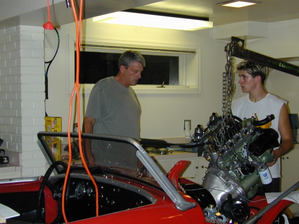
 

I Know it Will Fit!
I Know it Will Fit!

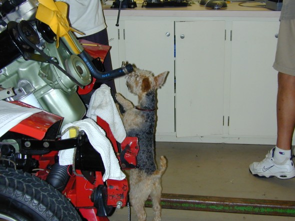
A Little Help from Bella

A Little Help from Bella

Installed new heater water valve in head – used cap screws instead of studs.

Installed thermostat cap

Installed new water drain tap to block

Discovered that we needed a 1275 yellow plastic 6 blade fan along with a spacer so that the blades will clear the breather on the timing cover – frustrating!

Installed generator. Will convert to the alternator after we get the motor working properly at a later date.

Put 2 1/2 pints of Valvoline synthetic gear lube in the transmission. This required a long length of clear plastic tubing to the transmission fill hole on the driver’s side of the tranny.

Installed new intake manifold from MiniMania and new carbs from Moss. We later discovered that this manifold sat too high and resulted in a dented bonnet. It had to be replaced with a stock unit.

Installed new oil filter and filled the engine with oil – 30 weight real oil for break-in. 4 1/2 quarts.

Put a little carb damper oil in each carburator.

Bled the brakes and the slave cylinder for the clutch.

Installed new fan blade with spacer and radiator.

Reconnected oil pressure line

Reconnected water temperature gauge.

Installed driveshaft. Beat the universal joints unmercifully and they finally came apart. Installed the new ones supplied by Rivergate.

Connected the speedometer cable.

Checked fan belt tension

Installed exhaust system which required fabricating a bracket for the rear mount.

Reattached the engine ground cable.

Installed a leather shift boot from a later model midget so that the datsun B210 shifter lever would fit a little better, rather than using the original metal boot.

Adjusted clutch slave cylinder pushrod

Installed new SU fuel pump in the engine compartment rather than at the rear bulkhead and ran fuel line to the carbs. This approach is not recommended, but everyone who has done it says that it has worked fine for them. The theory is that it gets too hot in the engine compartment, but others suggest that it is cool enough at this location. The mounting bracket is the same one used at the rear of the car. It is just bent to fit with nylon spacers.
new ignition wiring

New Ignition Wiring

SU Fuel Pump at Front
SU Fuel Pump at Front

Datsun Gearbox Fits

Datsun Gearbox Fits

Reconnected battery, generator, distributor and other electrics.

Poured a little oil down the banjo bolt to lubricate the oil pump.

Attempted to start the car, but it failed to fire. Had the car towed to Coachworks. We had set the carbs too lean to fire! After minor carb adjustment, and timing the car started and ran well.

Installed the bonnet and bumper. Discovered that the MiniMania intake manifold made the carbs sit too high. The carbs dented the bonnet when one of my friends attempted to force shut the bonnet by standing on the bumper.

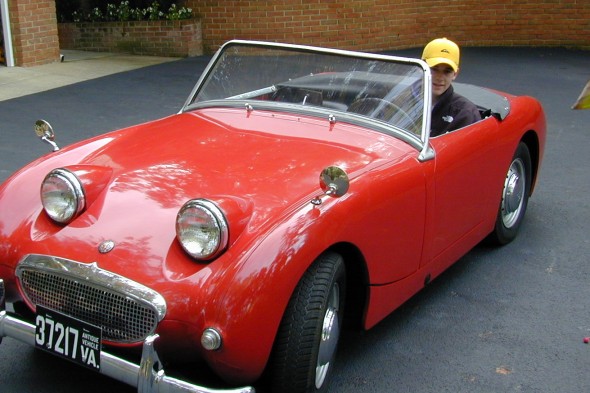
Then the proud moment came! I took My Bugeye out for its first drive.
Road Worthy