Front Shroud Badge Replacement

They just don’t make them like they used to! The shroud badge I mounted on the Healey around 2008 started to lose its color (enamel?) this year. I think the problem was that the entire badge was chromed and then the enamel was applied. It is hard for anything to stick to chrome indefinitely. So, my 2008 badge wasn’t as good as the original.

Shroud Badge Losing Enamel

But…the badges available now are not as nice as the ones that were available when I did the restoration. I had to return one vendor’s badge that wasn’t very good at all. I then ordered one from AH Spares, part # BAD-107, and while the metal is thinner than the one it is replacing, it does have the curvature of the shroud and the lettering and enamel look pretty good. We will see how long the enamel holds up on this badge! The badge has two studs and came with the fixing washers and nuts – a 5/16″ wrench is used.

Replacement Shroud Badge

Replacing leaking RH Lever Shock

I use Bilstein tube shocks on my car having installed Udo Putzke’s mounting kit when the the car was restored. Details may be reviewed on a previous post https://valvechatter.com/?p=3365 regarding the front and rear suspension. The kit uses the original lever shocks without the pistons as the upper “A” arm of the front suspension. The right front shock was leaking oil. 

I returned the shock to World Wide Auto Parts run by Dave Caldwell. Dave had rebuilt my shocks about ten years ago. In spite of the time that has passed, Dave honored the lifetime warranty and sent a fresh rebuild to me. Amazing!

To replace the shock, I first placed the car on four jack stands and then removed the right front wheel.

On Jack Stands for Shock Replacement

I then placed a floor jack under the spring pan and raised the pan until the shock arm was free of the rubber rebound pad.

Floor Jack to go Under Spring Pan

I then loosened the top mount for the bilstein tube shock using a 3/4” wrench and loosened the lower mount for the bilstein tube shock with 5/8” wrenches.

Bilstein Shock Lower Mount

I then removed the split pin on the castle nut securing the fulcrum pin.

Split Pin in Castle Nut

I then progressively loosened the castle nut and used it to tap out the pin with a soft hammer.

Gradually Knocking the Fulcrum Pin Out

Then using a drift I tapped out the bolt all of the way, leaving the drift in its place.

Fulcrum Pin Removed

Using a large screwdriver I levered the trunnion for the king pen off of the shock absorber.

Screw Driver as Pry Bar

It won’t move far, but I put a large jackstand under the hub to prevent any stress.

Jack Stand Supporting the King Pin and Trunnion

Using a 9/16” socket and ratchet I loosened and remove the right front shock bolt to chassis.

Loosening Front Shock Bolt

Then using an Allen wrench through the access hole in the bracket, I loosened and removed the left front shock bolt to chassis.

Allen wrench to Remove Left front Shock Mount

I then removed the left-hand rear and the right-hand rear shock bolts to the chassis with a 9/16 inch deep socket and ratchet.

Removing Rear Shock Mount Bolts

I was then able to lift the shock away from the car. It was immediately obvious that the shock had been leaking!

Obvious Oil Leak

The next step is to clean up the mounting area before installing the new shock.

Clean and Ready for New Shock

I then loosened the shock arm bolt/nut 9/16” wrench to make it easier from the arms to go over the trunnion bushings.

Loosen Shock Arm Bolt

The next step is to install the new shock to the chassis by first screwing in both of the engine side (rear) bolts. These are grade 8 3/8”-24 x 1 1/4”. This is made easier with some long extensions and a universal joint before the socket.

Long Extension and Universal

In this case, the completion of the installation really is the reverse of the removal process!


Rear Rally Overrider Modification

I have never been happy with the Rally Overrider brackets I installed during the restoration process for the Bloody Beast. I ordered the brackets from Cape International and while they fit (I guess), the Rally Bumpers protruded too far from the rear shroud.

Cape International Rally Overrider Brackets

I had resigned myself to finally solve the problem with some cutting and welding. However, I met a new Healey enthusiast who was just finishing up his restoration and he mentioned to me that he had purchased his Rally Overrider brackets from AH Spares and that he was pleased with them. He showed me a few photos and I was sold. I ordered a pair of the brackets from AH Spares for $73.00.

It was immediately obvious upon inspection that the AH Spares brackets were shorter and the angle of the brackets where they mount with the Overrider was also considerably different. The AH Spares bracket is laying on top of the Cape International bracket in the photo below. The much sharper angle on the AH Spares bracket tucks the rally bumper up and under the shroud nicely, paralleling the shroud curvature.

Old and New Brackets

I decided to replace the RH side bracket first. The initial step in the replacement process was to remove the battery and just to make things a little easier I also removed the master ground switch near the battery. This provided access to the two 3/8″ bolts that secure the bracket to the frame of the car.

Battery and Master Ground Switch

With the battery removed one can see the forward bolt for the bracket mount:

Battery Brace and Forward Bracket bolt

To get to the rear-most bracket bolt I removed the master ground switch:

Master Ground Switch

It was then just a matter of bolting the rally bumper to the bracket and sliding the assembly into place. I then tightened all of the bolts, replaced the battery and tray as well as the master ground switch. I then moved to the left side of the boot.

Of course, to access the LH bracket one must remove the spare tire!

Spare Tire Removal

I then installed the LH bracket and rally overrider as I had done the RH side and replaced the spare tire and cover. While I was at it, I checked the air pressure in the spare and found it to be 11 pounds so I topped that up to 30 and was glad for the reminder to check spare air pressure!

I am quite happy with the finished product. The rally overrider bumpers now fit as they should and I think it is a much better look.

Rally Overrider with AH Spares bracket

New Overrider brackets Installed

Rear View of New Rally Overrider Install

One more task completed and checked off the list!


Engine Oil Change

A pretty simple and straightforward first step. I have a spin-on oil filter adapter and use a K&N HP-2009 Filter with a little under 7 quarts of Hick’s Oils Collector’s Choice 20W-50 motor oil. A fresh copper crush washer was used under the oil sump drain plug. The drain plug on my aluminum sump requires an 11/16″ wrench for removal.

I ordered the oil from Moss Motors and the filters directly from K&N. You don’t need a filter removal tool for the K&N filter as the canister comes complete with a 1″ wrench fitting! 

K&N HP-2009 Oil Filter


Hick’s Oils Collector’s Choice 20W-50


HD8 Carb Initial Tuning

I have read many “how to” documents concerning the tuning of the SU HD8 carburetors including the “Bible” – SU Carburetters Tuning Tips & Techniques

SU Tips

and Des Hamill’s The SU Carburetter High-Performance Manual. But, The summary put together by Steve Byers is about the best single document specifically for HD8 carbs that I have reviewed. Byers Adjustment of the HD8 Carburetor

Steve’s document describes the process of tuning the carbs in layman’s terms in an easy step-by-step process. So, here is what I did:

As Steve indicates, the first thing to do is run the engine until it is at normal running temperature and then begin the tuning process. Of course, in my case, I am making the initial settings before actually operating the vehicle. Following my installation in the car I will do as Steve says and get the car to operating temperature and then I will essentially repeat the tuning steps.

Next I removed the dashpots from the carbs with piston and springs and carefully stored them aside to insure no damage to the needles. At this point I have no oil in the damper tubes. I make sure that I know which assembly is for the front and for the rear carbs – they need to be returned to the proper location.

I then backed off the Fast Idle Adjusting Screw for each carb to ensure that neither screw is touching its throttle shaft stop lever. I cut a strip of paper from a note card to slide between the screw and its stop to test this and to get both the front and rear the same.

Fast Idle Adjusting Screw

I then loosened the screws/nuts (5/16”) on the interconnecting shaft clamps so that each throttle plate can be rotated independently of the other. I then rotated each throttle plate fully closed by turning its shaft as far as possible. With each throttle plate held fully closed, I re-tightened its shaft clamp screw/nut. Both stops should reach full travel at the same time.

As Steve notes, “There is an extended arm on each interconnecting shaft clamp with a pin that fits into a slot on the carb throttle shaft lever. The pin is smaller in diameter than the slot, so it’s possible to adjust the clearance between the pin and slot (by rotating the clamp) to occur at the upper edge of the slot, at the bottom edge, or both. I adjust mine on both carbs so that most of the clearance occurs at the top. Clearance anywhere except at the top will allow some throttle shaft rotation before the throttle plate begins to open. The SU carburetor manual specifies 0.006 clearance between the bottom of the pin and the edge of the slot, but this is pretty much impossible to measure due to poor access.”

Steve then suggests, using a small straight edge to determine flushness (I use the end of a 6” steel scale), turn the Jet (Mixture) Adjusting Screw for each carburetor until the jet is flush with the bridge of the carburetor (the bridge is the part in the carburetor throat that the piston sits on when it is down). Turn the Jet (Mixture) Adjusting Screw (#2) counterclockwise to raise the jet (leaning), clockwise to lower it (richening).

Jet Adjusting Screw

Once the jet is flush, turn the Jet (Mixture) Adjusting Screw three turns clockwise (rich) as an initial setting. Where I depart from Steve just slightly, is that I did not worry so much about the number of turns of the jet adjusting screw. Instead, I use a micrometer to adjust both jets the same amount – .0625″ or 1/16″.

Jet Adjustment with Micrometer

I then re-installed the carburetor pistons, springs and suction chambers.

I replaced the original Whitworth screws with number 10–24×9/16 inches stainless socket screws. With a 5/32″ Allen wrench these are much easier to access than the original screws.

10-24 socket head screws for Dashpots

Again for initial setting, I turned the Slow Run Valve (Slow Idle) Adjusting Screw for each carburetor clockwise as far as it will go until it bottoms lightly on its seat. Then, I turn it back counterclockwise two and one-half turns.

I then installed everything onto the car and assembled all of the components as described here. Once in the car, I reattached the choke cables and their mounting brackets as well as the throttle cable.

The next step is to install the new fuel delivery system from the hard fuel line coming from the fuel pump up to the carburetors before I can start the car and make final carb adjustments.

Oil Leaks

Of course, the standard joke is that the car wouldn’t be British if it didn’t leak oil. My car isn’t bad, but when I had it up on the lift, I noticed some oil on the RH side of the frame.

Oil Leak on Frame RH side

The leak got me looking around. I seam to have oil leaking from the alternator mounting bracket suggesting that I need to replace that gasket and reseal the bracket. Not that the frame oil came from the oil sump, but I checked the oil sump mounting bolts and noticed that many of them were not tight. A 7/16″ socket with an extension had those bolts tightened up in no time. I will keep a watch on this area, as I may need to replace the sump cork gasket as well. I will come back to this problem and specifically the alternator bracket seal a little later.

I observed that the rear differential drain plug was also leaking a little gear oil. I took this as an opportunity to change the gear oil and put some sealant on the plug threads. The manual states that the capacity of the rear axle is 1.7 lites, but I just fill the diff until oil begins to drip out to the fill plug hole.

Shell Spirax HD Gear Oil SAE 80W-90


Valve Adjustment

I really don’t recall when I last checked valve clearances, so as part of this ten year renewal process adjusting clearances was an obvious item for the checklist. You really don’t need many tools to take care of this project. An 8mm socket is used to loosen the hose clamps on the crankcase breather apparatus, a 1″ open end wrench is used to loosen and remove the two rocker cover cap nuts with cup washers and rubber bushes, a medium-size flat screw driver is used to turn the rocker adjusting screws, a 9/16″ box wrench is used to loosen and tighten the adjusting screw nuts, a feeler gauge is used to adjust the gap between the adjusting screws and rocker arms and finally, a spark plug socket and ratchet is used to remove the spark plugs.

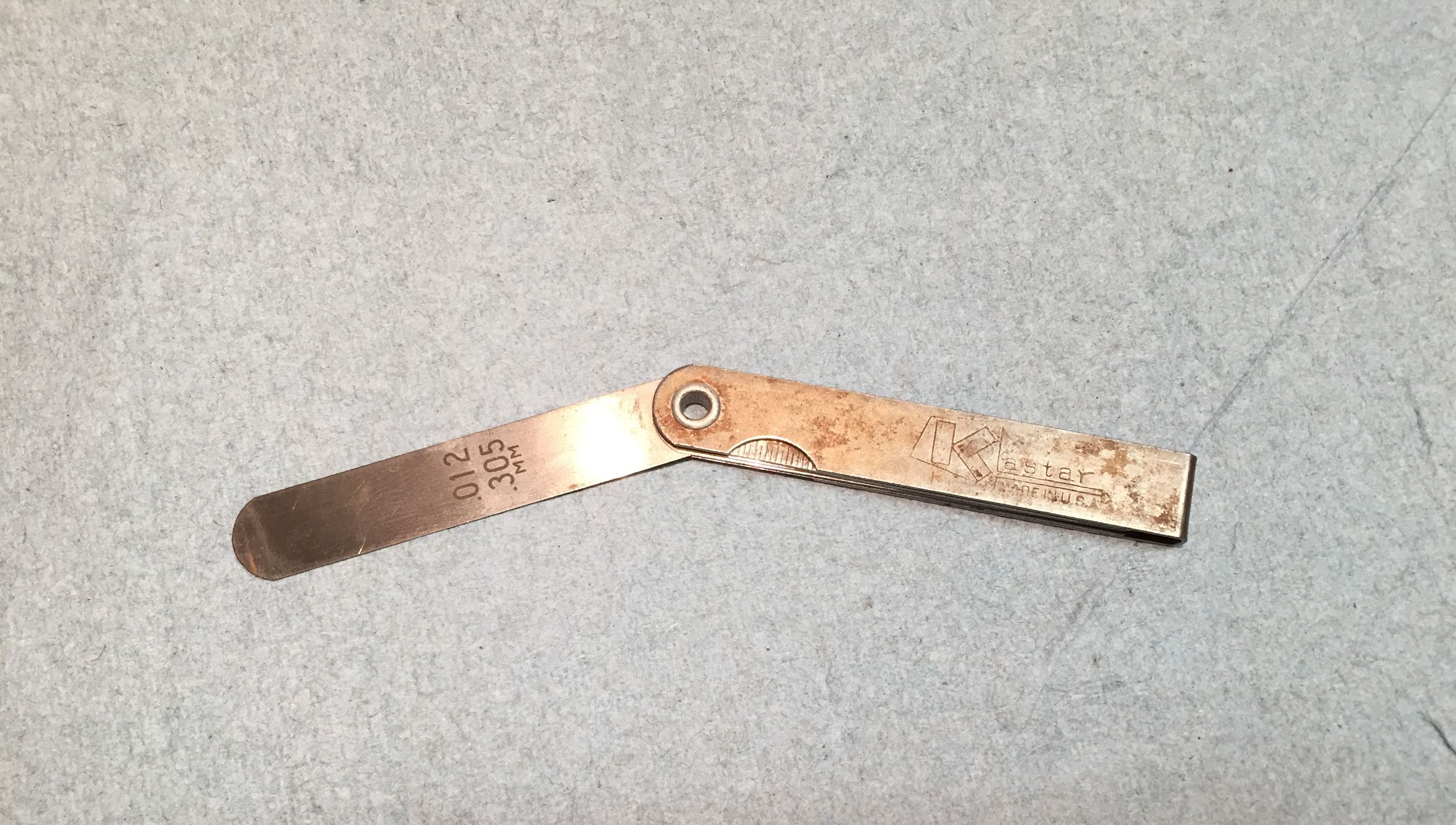
I purchased my feeler gauge at the same time I acquired the Healey in 1971. It is still in my tool bag after all of these years:

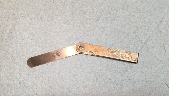
Forty-seven year old feeler gauge

The workshop manual call for a clearance of .012″ or .3mm between the adjusting screws and the rocker arms for both inlet and exhaust valves. There are lots of good resources on the web and on Youtube that describe the process.

I loosened the breather hose clamps and moved the hoses and clamps out of the way so that the rocker cover can be removed.

I then cleaned the base of the rocker cover to make sure no debris would fall into the cylinder head when the cover is removed.

I then loosened and removed the cap nuts, washers and rubber bushes from the rocker cover and carefully lifted the cover off the engine, taking care to keep the silicone gasket in place so that it could be used again. The cover was then cleaned and set aside. I also carefully cleaned the surface of the head where it mates with the cover. 

Next, was the removal of the spark plugs. This is done to make it easier to roll the car when needed for the valve adjustment process. This is also a good time to inspect and clean the plugs. Mine are visually new so not much was required. Care must be taken to ensure that the plug cables are numbered so that they are reconnected in the proper sequence!

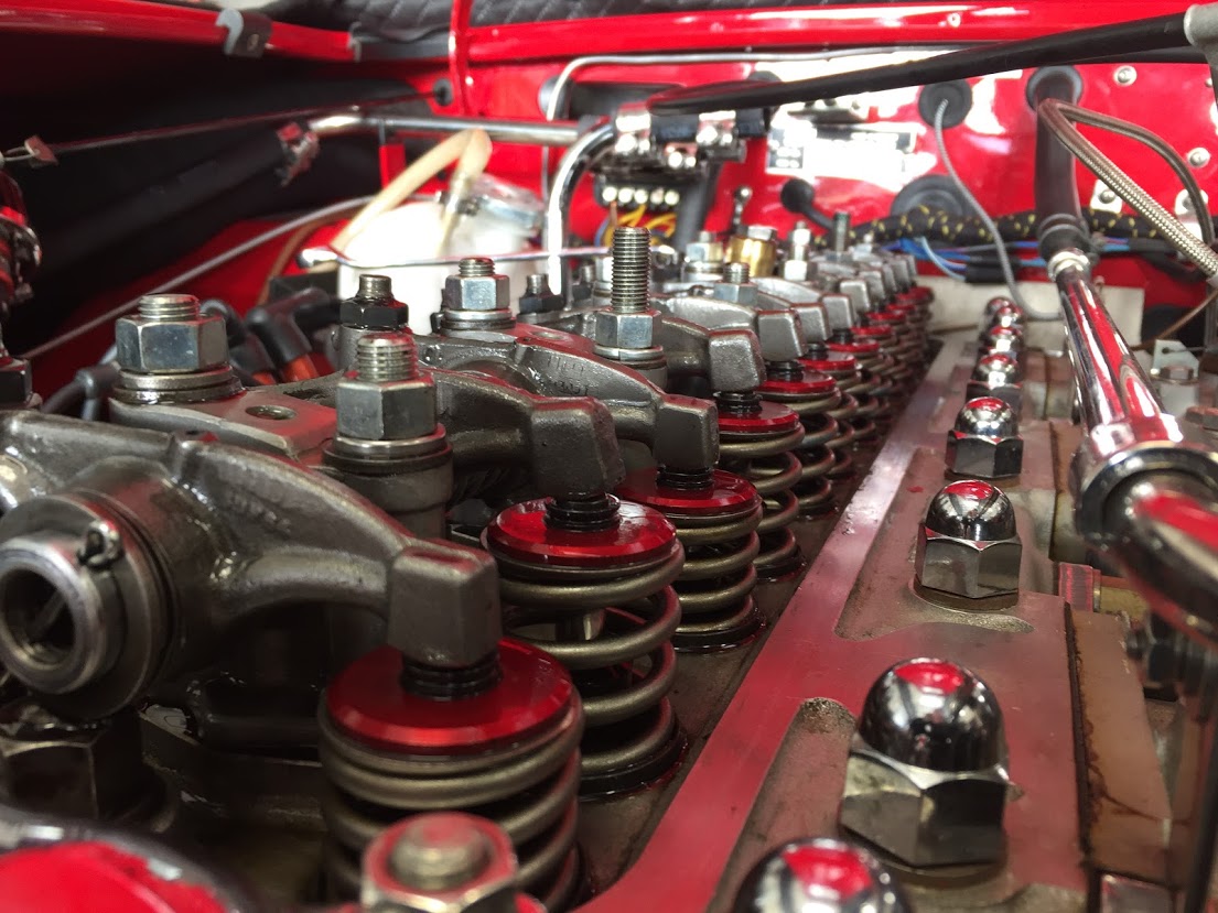
I guess I should bathe in motor oil each morning because it sure makes for good preservation of surfaces. The images below show the Dennis Welch head assembly after almost ten years on the car!
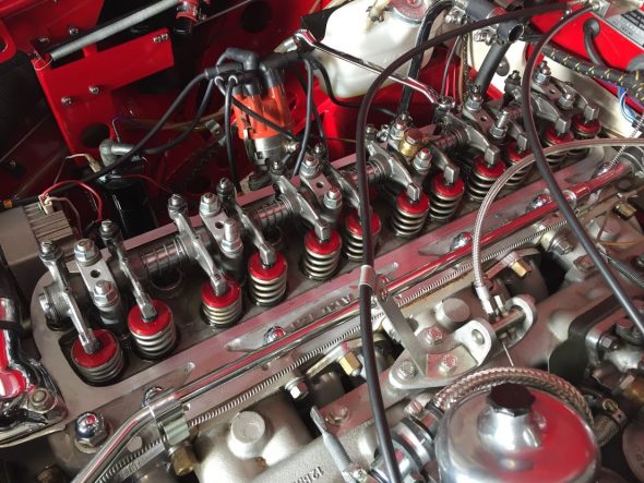
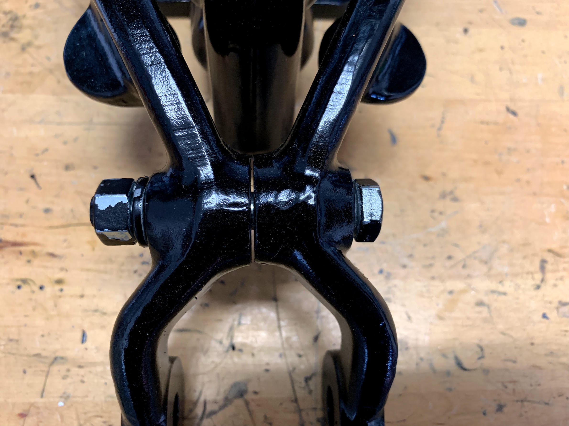
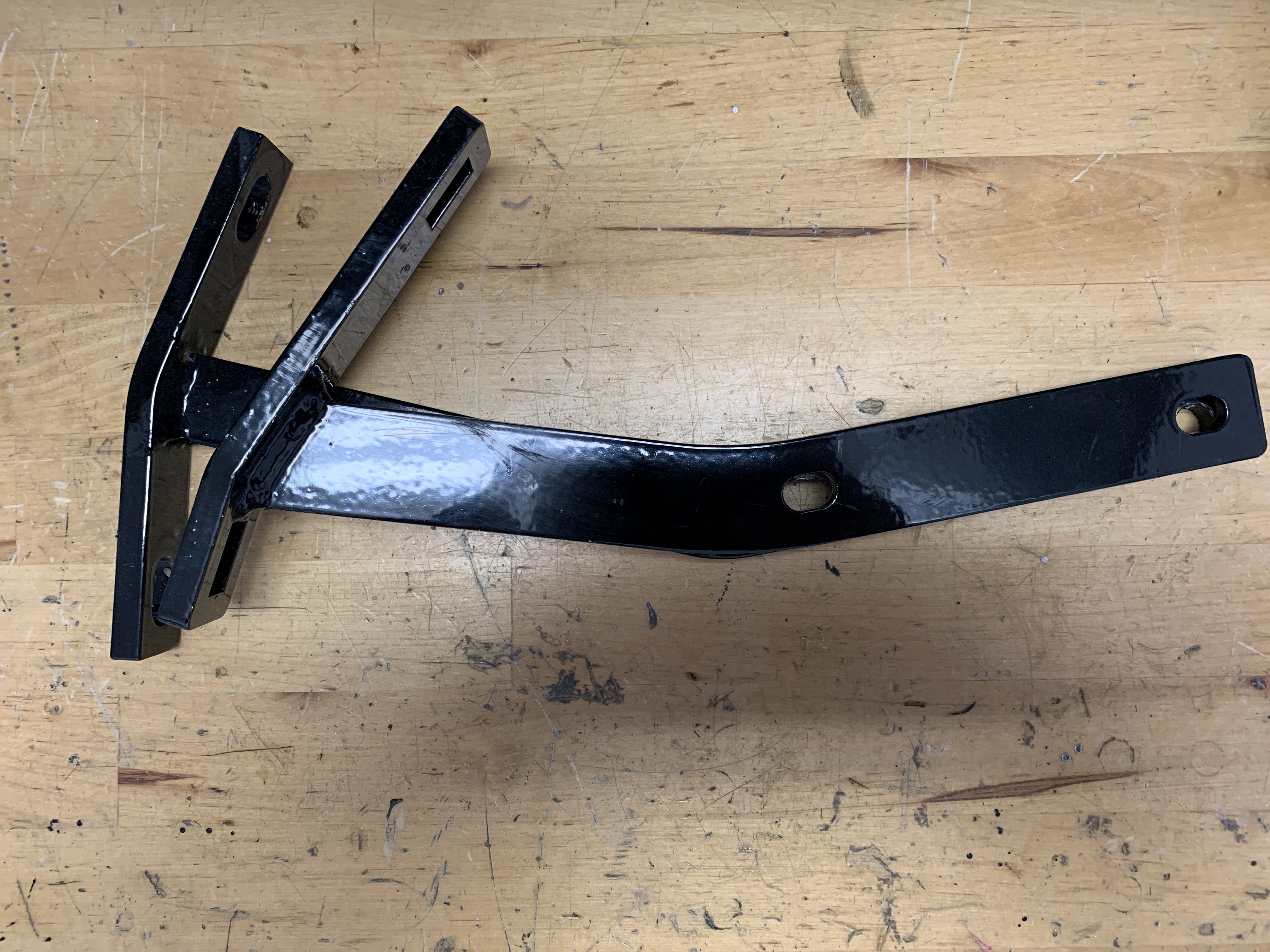
Rocker Arm Assembly

Rocker Arm Assembly

Checked the clearances of each valve as I proceeded. Most were very close to spec although I had two that were a little tight.

The “Rule of Thirteen” is used to know which valve to adjust on a 6 cylinder engine. If valve #1 is open (when the adjuster side of the rocker is up, and the spring side is down) then which valve do you adjust to get to a total of thirteen? The answer is valve #12. When valve #8 is open (up) then to get to a total of thirteen we need to adjust valve #5, and so on. 

Valves open and close in pairs, therefore we can adjust the valves in pairs in accordance with the table below:

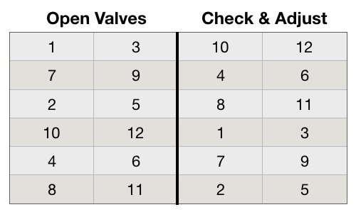
Valve Adjustment Table

I backed my car into the garage – nose out – as far to the rear as possible and then let it sit over night so the engine would be completely cold.

The next day I put the car into 4th gear and pushed it forward and in my case the springs on rockers #1 and #3 began to depress. I continued to push the car forward until the springs were fully depressed so that the adjusting screws for valves #10 and #12 were ready to be checked and adjusted. You can either watch the spring movement carefully or you can put fingers on the rocker arms to sense the change in movement. Whichever method works for you is fine. Some people push the front tire to move the car while in gear, others use a wrench on the crank nut or on the alternator/generator pulley nut, or just pull on a fan blade in a clockwise motion (be careful).

Once the adjuster screw is identified that I wanted to adjust (in this case #10), I loosened the adjuster nut, placed my .012″ feeler blade between the rocker and the valve stem and tightened the adjuster nut until the feeler blade was snug and while carefully holding the screwdriver on the adjusting screw so that it would not move (a little tricky) I tightened the nut tightly. I then checked the feeler gauge and readjusted if it was too tight or too loose. This process takes a little practice, but you get the hang of it pretty quickly.

I then moved on to the #12 valve and completed the same process. 

I then slowly pushed the car forward again until the valve springs for #7 and #9 were fully depressed. I then adjusted valves #4 and #6.

I continued with the progression shown in the table above until all valve clearances were properly adjusted.

Next the car was put in neutral and pushed to the rear of the garage again. Then I repeated the full process checking the clearances of each valve a second time. In this case double-checking is certainly a good thing and worthwhile!

Valve adjustment was then complete. 

Sealing The Rocker Pedestal Studs

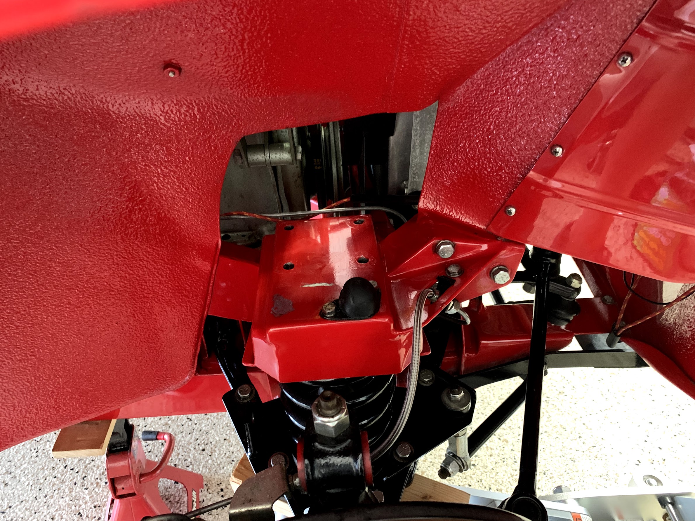
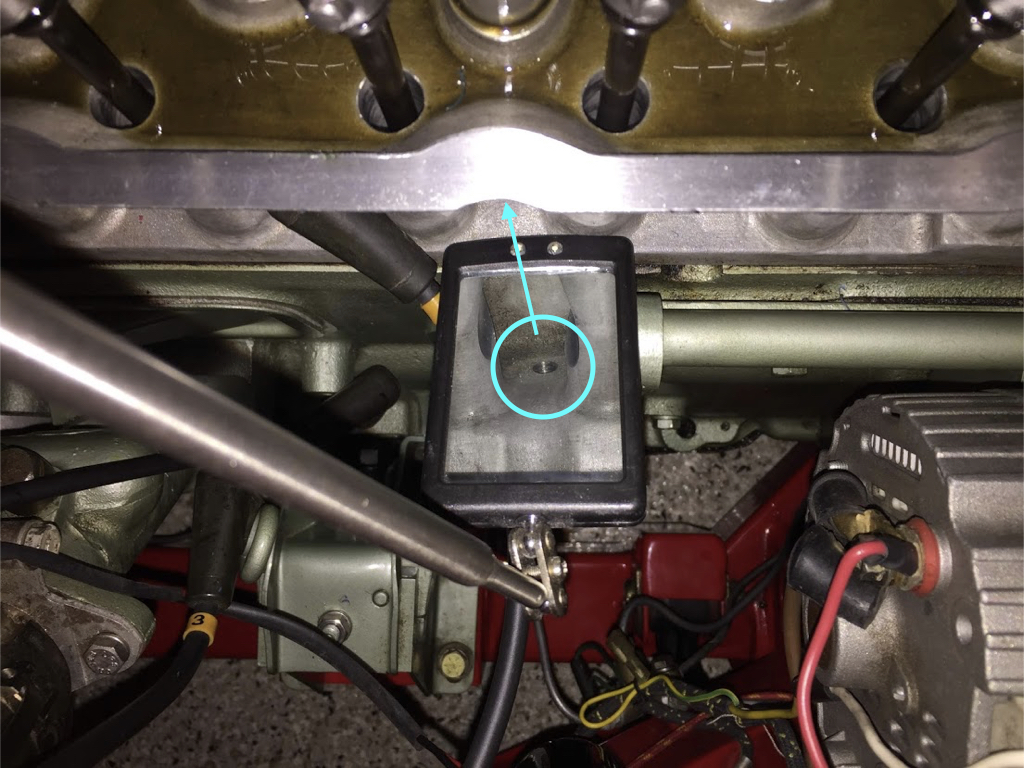
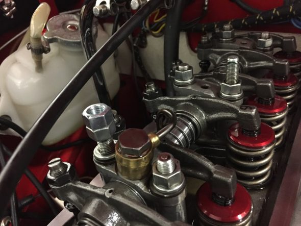
Fellow Healey owner Steve Gerow pointed out that one needs to be sure to apply sealant to the rocker pedestal studs otherwise oil can seep through the studs and leak into the cavity in which the park plugs are located. I noticed that on my car I was getting a little oil into two of the spark plug cavities, so, after adjusting the valves and before replacing the spark plugs and rocker cover I decided to pull the rocker studs and apply some high temperature sealant to the threads.

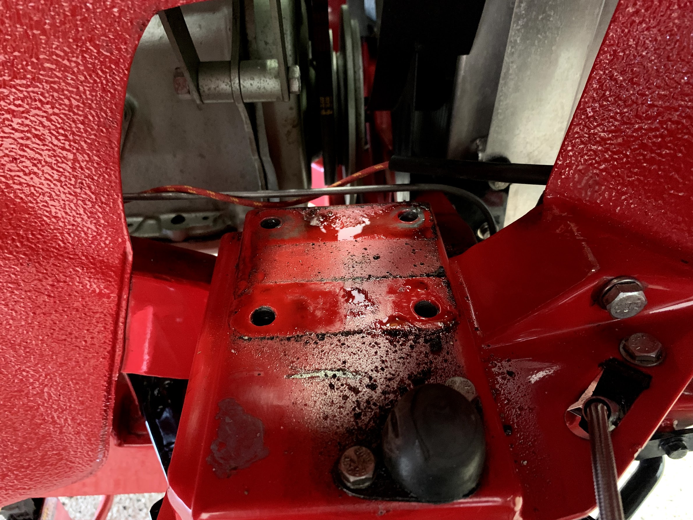
If one uses a mirror you can see where these rocker stud holes are drilled all the way through the head. If not properly sealed one can see that a leak could easily develop.

Rocker Pedestal Stud Hole in Spark Plug Cavity

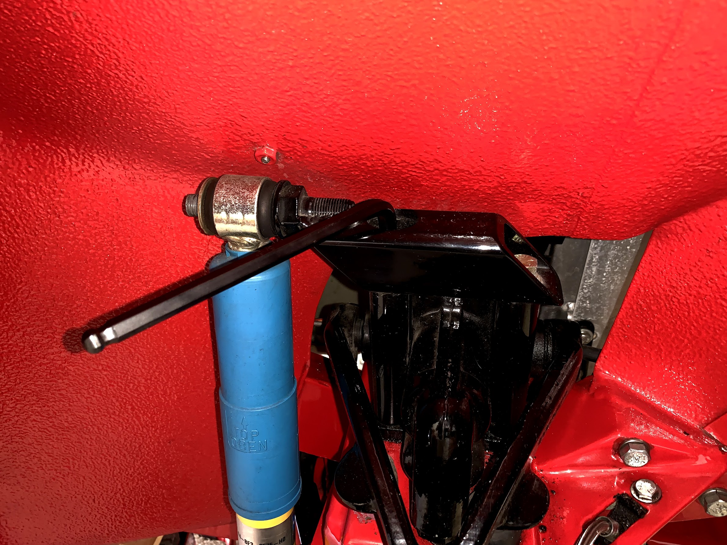
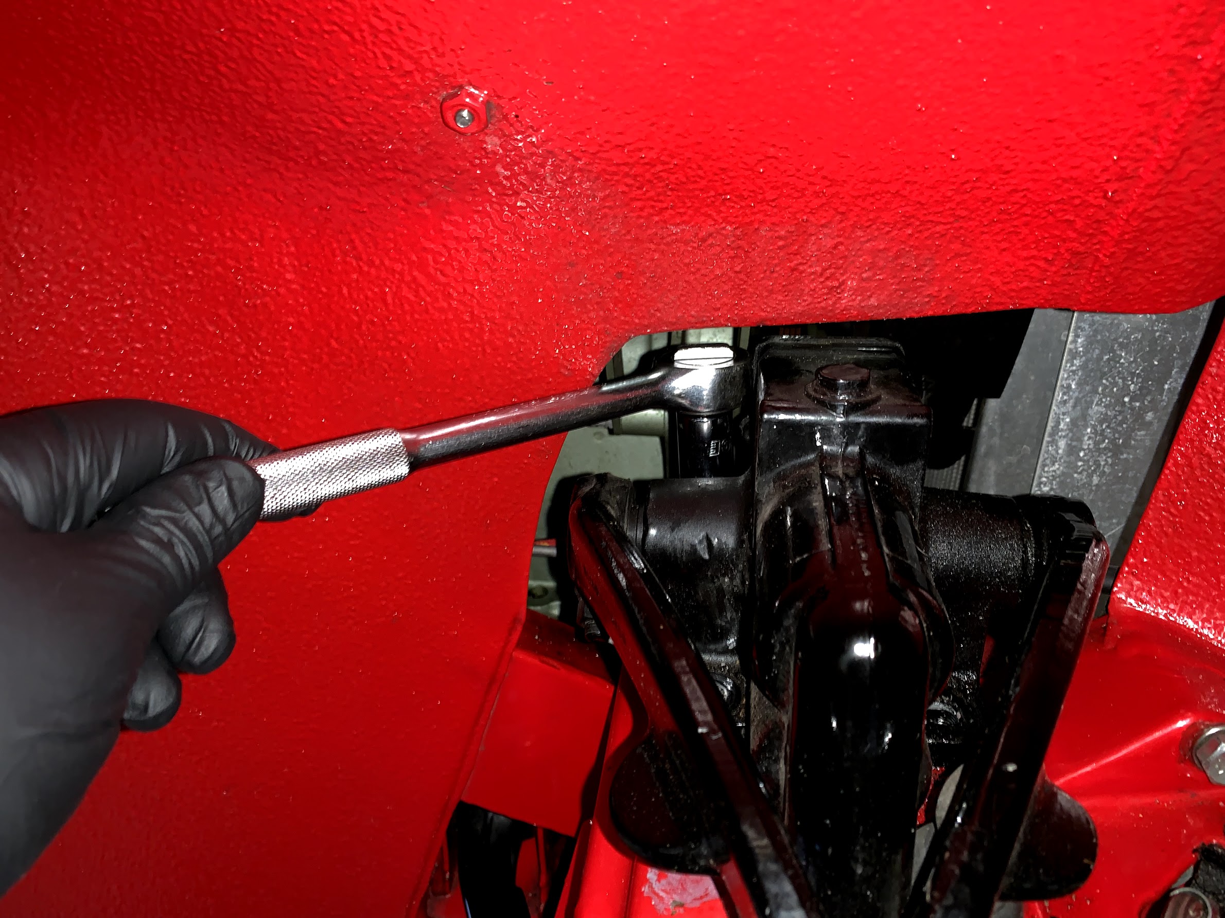
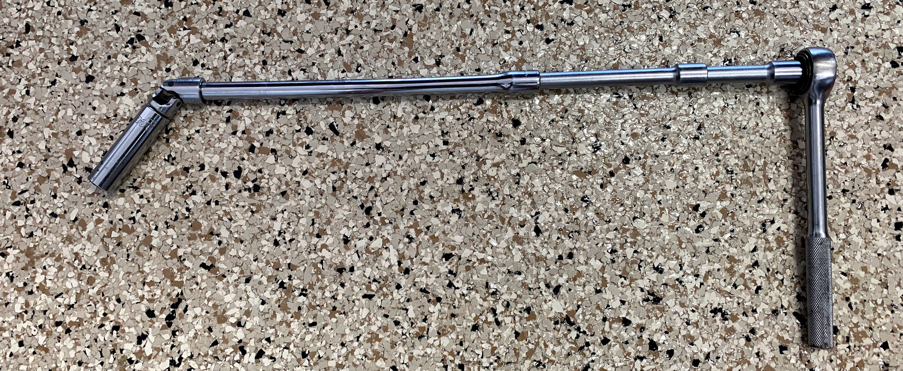
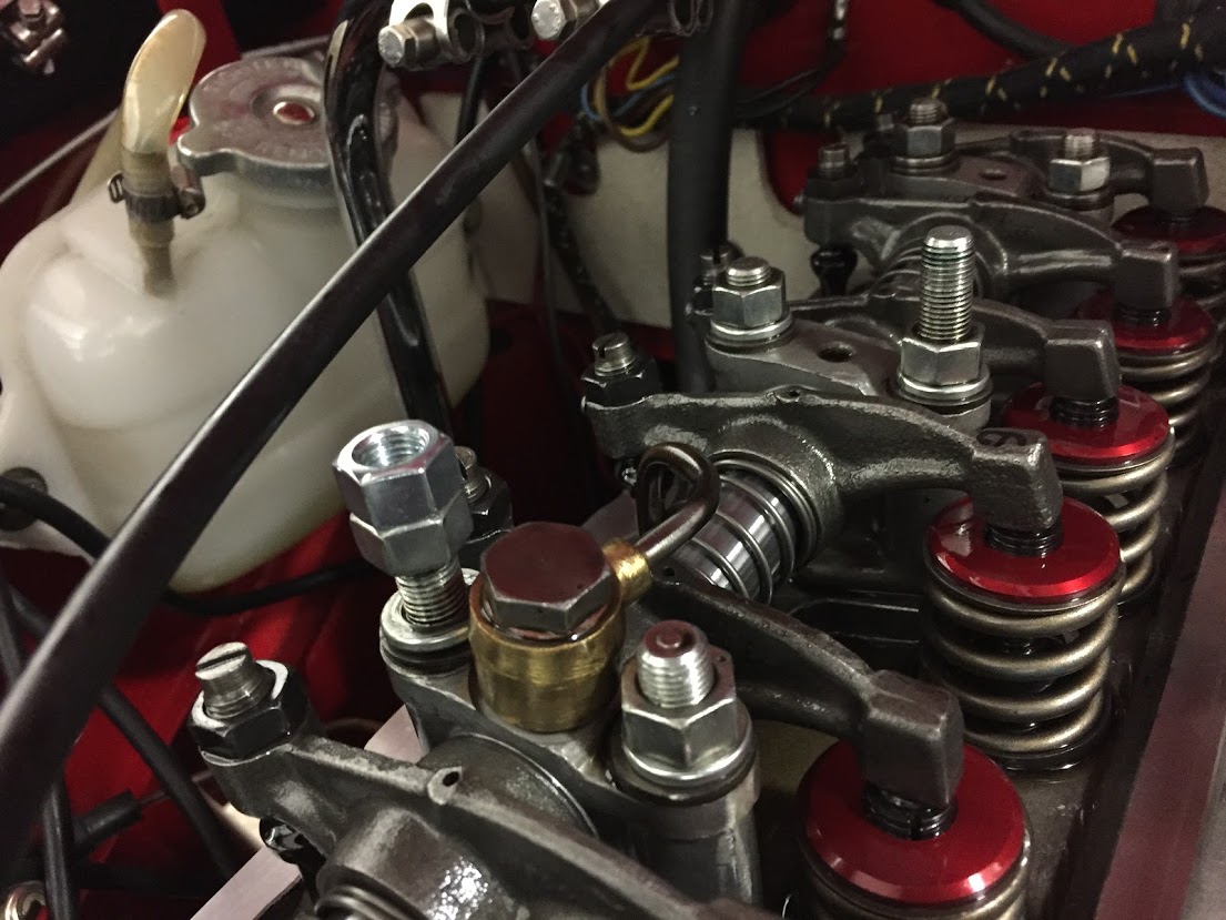
To remove the studs I used the double-nut procedure where one screws a second nut onto the stud and tightens it against the existing nut. A wrench can then be used on the lower nut to slowly turn the stud out of its home.

Double-nuttting studs

Following Steve’s suggestion I cleaned the stud and cylinder head threads with brake cleaner and then blew them dry with compressed air. I applied Permatex high temperature thread sealant to the threads per the instructions. 

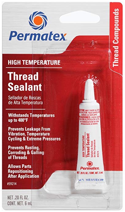
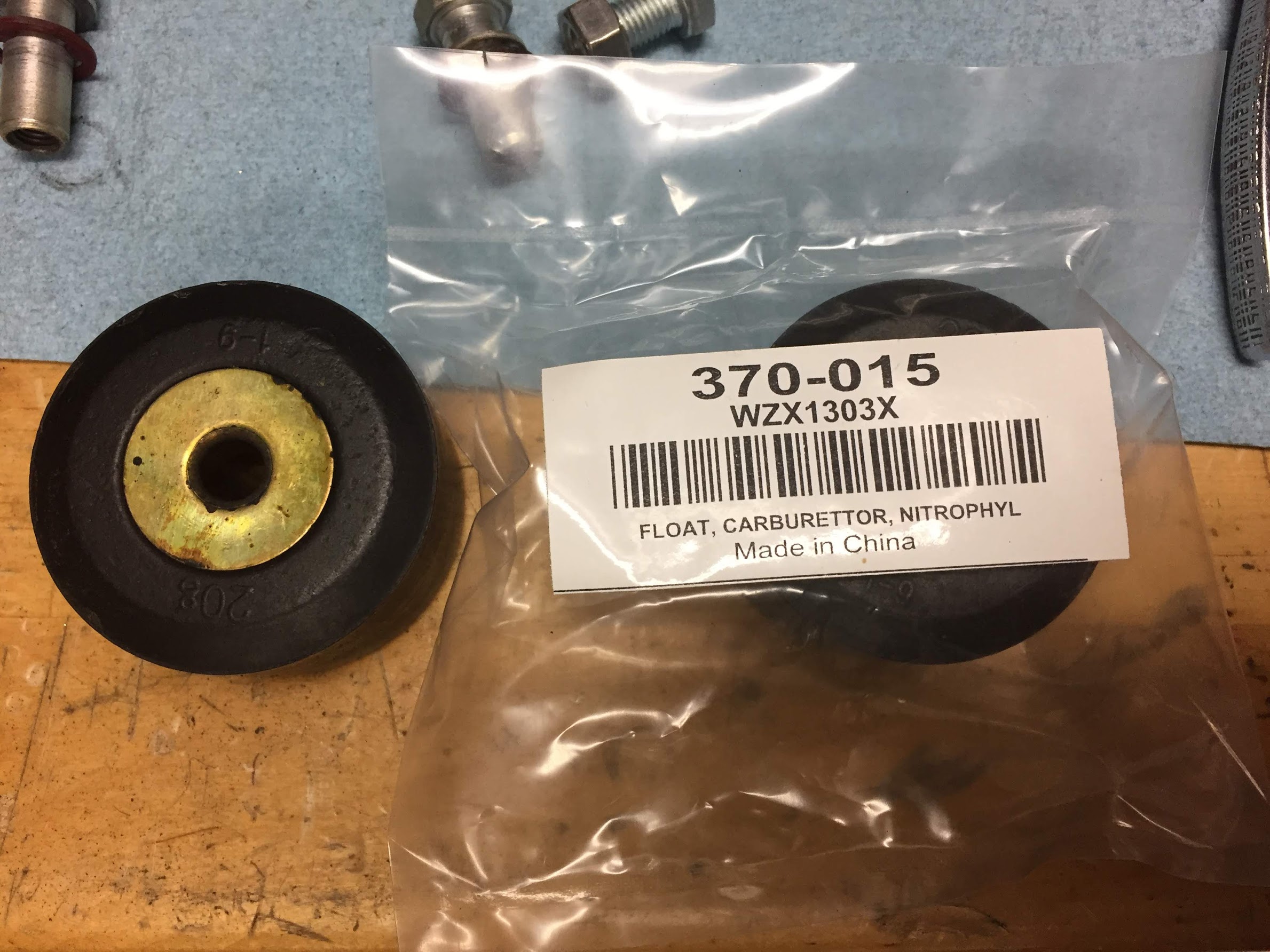
Permatex High Temperature Thread Sealant

The last step was to torque the rocker pedestal stud nuts to 25 ft. lbs. Another job complete.

Rear Axle Breather Replacement

Most of the vendors sell a plastic breather for the threaded hole in the Healey’s rear axle. However, a fellow in the UK sells brass equivalents from vintage Land Rovers that fit perfectly. While the plastic component works just fine, I couldn’t resist replacing it with a clearly superior quality brass piece. It was a quick switch-out.

Axle Breather

HD8 Carb Rebuild

Since I had removed the carbs to install the new intake manifold, I decided it might be a good idea to go ahead and rebuild the carbs. They didn’t have many miles on them, but it has been about eleven years since they were last rebuilt and although I wasn’t experiencing any leaks it seems like a good time to go ahead and replace the bushings, rubber seals and diaphragms.

Joe Curto has done my rebuild work in the past and I was always very happy with Joe’s work. This time I decided to try Thomas Bryant in Wiscasset, Maine. Tom makes and installs delrin bushings for the throttle shafts. Others who have used Tom have indicated that they were very pleased with the performance of the delrin bushings. This is a link to his website and specifically to a rebuild post he did for HD6 SUs. https://thosbryant.wordpress.com/2018/03/03/su-carburetor-rebuild-hd-6/

These are a couple of images from his site that show the delrin bushing:

Delrin Carb Bushing

Delrin Bushing Installed

Tom also checked the throttle shafts for wear (they were OK), replaced the seal for the slow run valve, installed new jets and diaphragms, replaced several gaskets and adjusted the float bowl levers to the 7/16″ prescribed setting.

SU HD Float Lever Setting

I was very pleased with the quality of Tom’s work and his luck turn around. Very easy to work with. I recommend him to others without any hesitation.

This image illustrates the beauty of the bespoke Dennis Welch throttle cable aluminum bracket. The rod running through the bracket is free to rotate which prevents in cable binding when the accelerator is applied. In the image the proper operating angle of the cable is shown:

I also replaced the brass floats in the float bowls with new nitrophyl floats sourced from Moss Motors.

Nitrophyl Carb Floats

Nitrophyl Carb Floats Installed

Preventing Vapor Lock – Float Bowl Kouzies

The summer temps in southern Florida get pretty high and I have experienced a few episodes of vapor lock. Joe Curto who is well know as an SU carb guru sells some covers or “kouzies” for the car float bowls to help prevent boiling the fuel in the bowls. The “kouzies are made from “Koolmat” insulation material and are secured to the bowls with stitched velcro. Joe’s site indicates that the material offers continuous temperature protection to 650 degrees F and short term thermal exposure to 1000 degrees F. “Koolmat” claims to reflect 90% of radiant heat energy.

The covers are well made and fit nicely. Now, time will tell if they solve the vapor lock problem!

Curto Koolmat Kouzie

Joe Curto Float Bowl Cover

Kouzies Installed

Curto Kouzies Installed