Brake and Clutch Master Cylinder Replacements

I am seeing a very slight seeping of brake fluid around the clutch master cylinder on the pedal box inside the cockpit. So as a preventative measure I’m going to go ahead and replace both the brake and clutch master cylinders. This was last done in 2014.

The original manufacturer of the master cylinders was Girling, and they are still available today. I am counting on them being a higher quality than what’s available from many of the typical vendors. These masters came from Pegasus auto racing and cost $125 each.

The clutch master cylinder has a .62 inch bore while the brake master cylinder that I’m using has a .75 inch bore. As shipped, the master cylinders have threaded pushrods to make them adjustable in length. I will replace the adjustable length push rods with the push rods that are currently on the master cylinders on the car.

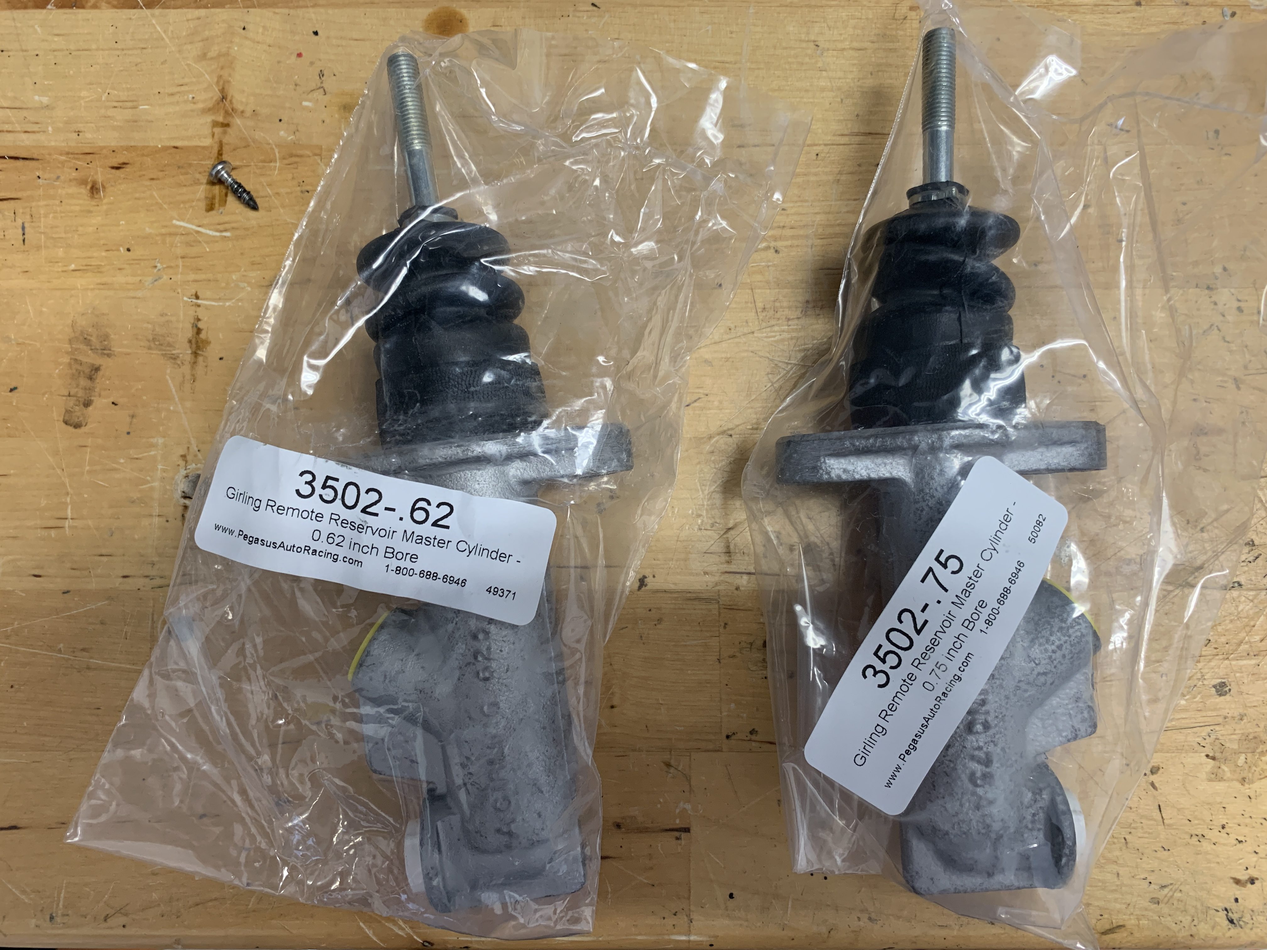
Girling Master Cylinders

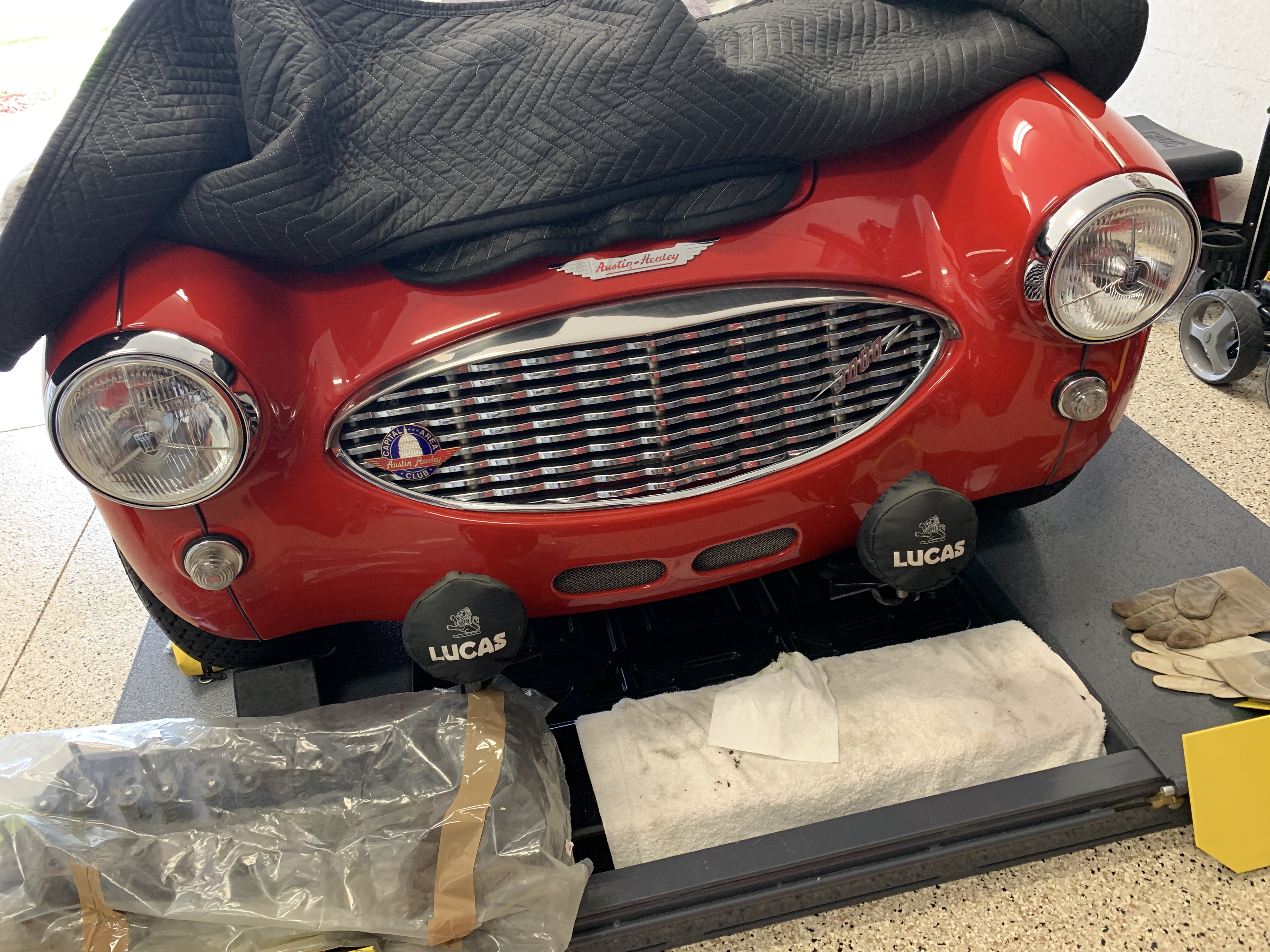
I’m going to tackle the clutch master cylinder replacement first. In preparation for the work I have raise the car onto jackstands. This will make it easier to get to the bleeder valves on each of the brake calipers at the wheels.

Bloody Beast on Jackstands Ready for Transplant

The parts manual states that the brake master cylinder should have shims and that shims for the clutch master are optional. That is how I have the master cylinders installed at the present time. However, the brake pedal is closer to the firewall than the clutch pedal (they don’t line up evenly) so when I put the new master cylinders in I will install the shims on both the brake and clutch master cylinders. The shims, or packing pieces, are only about 1/8″ thick and are made of aluminum. I sourced new shims from Moss Motors.

I used super glue to adhere the shims to the masters. If you don’t secure the shim to the master cylinder, it is very difficult to install the lower shims once the master cylinder is in the car.

Master Cylinder Shims

As a first step, I removed as much of the brake fluid from the reservoir as possible using a syringe. I used this same syringe later in the process to pull fluid through the clutch and brake hydraulic systems.

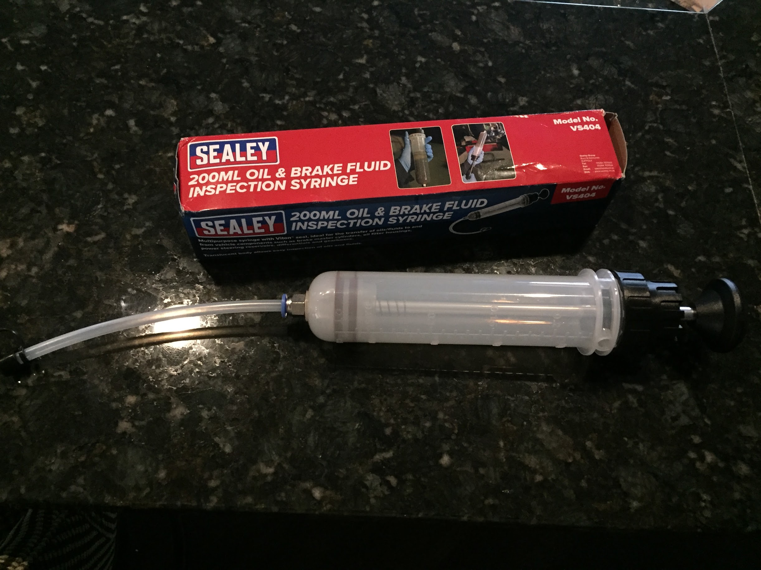
Sealey Syringe 200 ml

The tube within the reservoir holds the clutch hydraulic fluid.
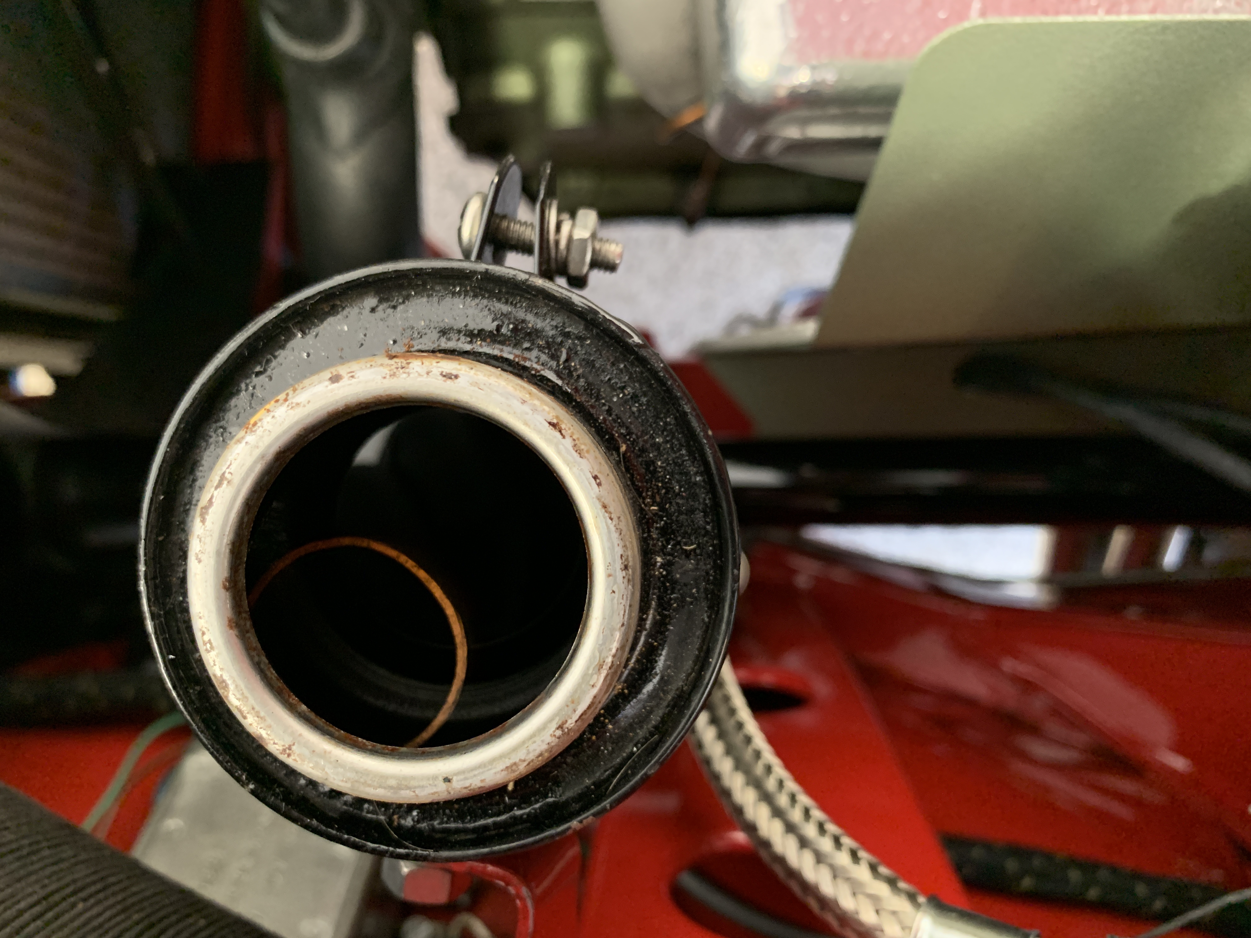
Fluid Reservoir

Of course, there is still hydraulic fluid in the lines but as you can see in this photo the reservoir for the clutch is now empty. I did this so when I disconnect the hydraulic pipes from the clutch master there is little fluid as possible to leak onto the car! Brake fluid eats paint so you need to be as careful as possible!

Empty Clutch Reservoir

My job is made a little more complicated because I replaced the Dennis Welch bleeder kit with one from Ol Phartz.

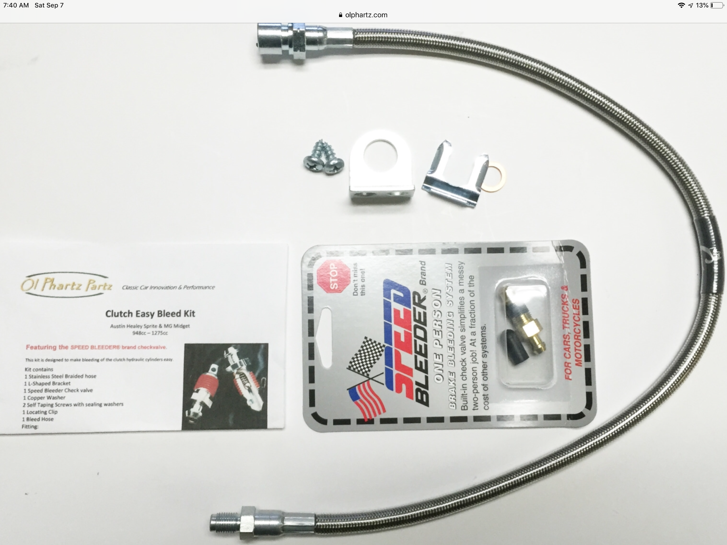
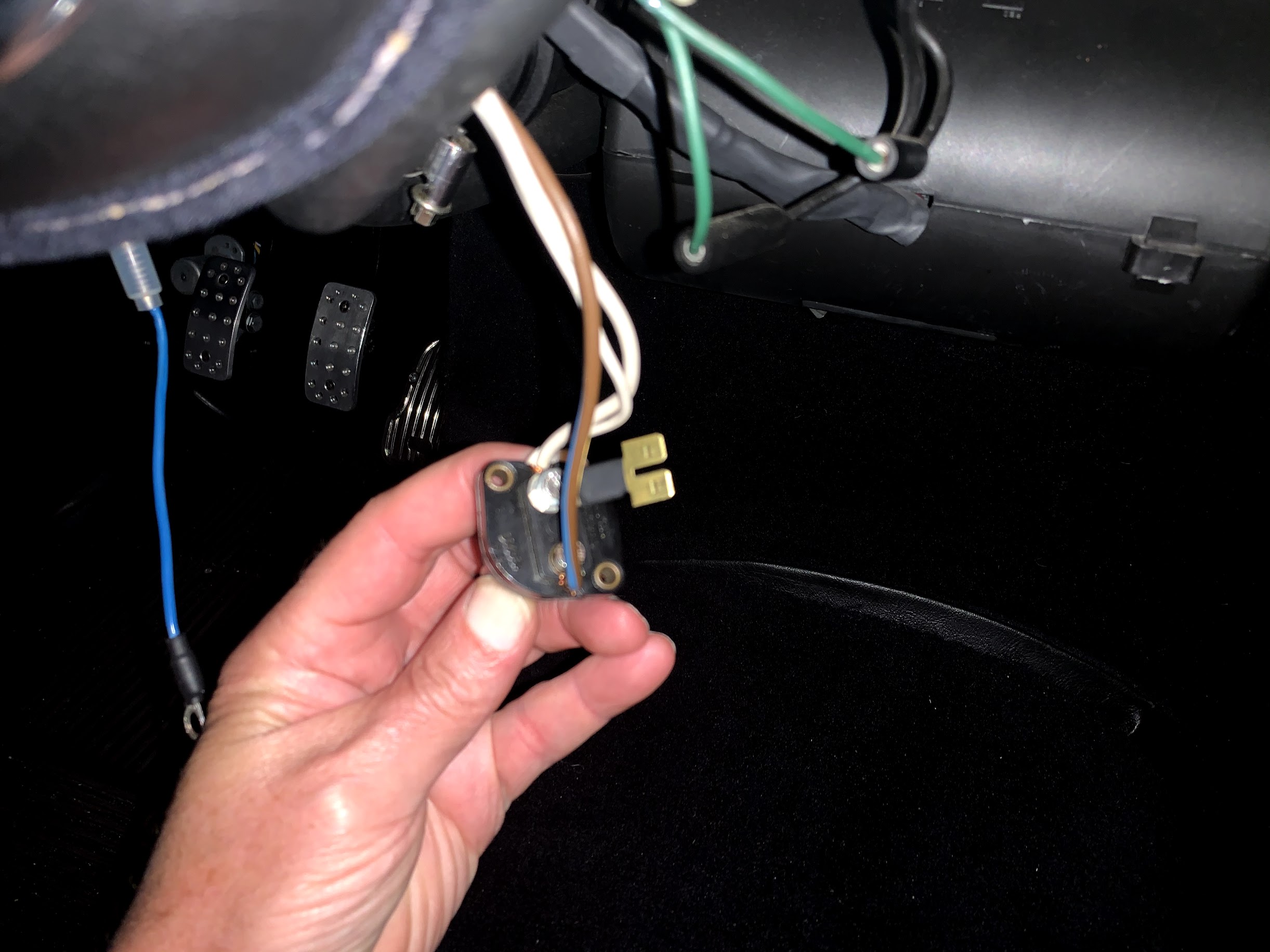
Ol Phartz Clutch Bleeder kit

Clutch Easy Bleed Kit Ol Phartz

The Dennis Welch kit tended to leak. Replacing the bleeder hose required access to the bleeder valve on top of the slave cylinder and you just cannot get there from under the car! This means that I had to remove the transmission tunnel and its extension from the interior. Argh!!! To do so means that I first had to remove both LH and RH seats and set aside the hardware. Then I removed the screws securing the transmission cover and the extension. These components were then set aside and out of the way. In my case I have cruise control and the control unit is in the ash tray. So, to be able to actually remove the transmission tunnel cover I had to first disconnect about a half-dozen wires below the car.

This is the RH side:

Transmission Cover Mounting Fasteners

And, the LH side:

Transmission cover Mounting Fasteners LH side

Removing the transmission cover extension was next:

Transmission Cover Extension

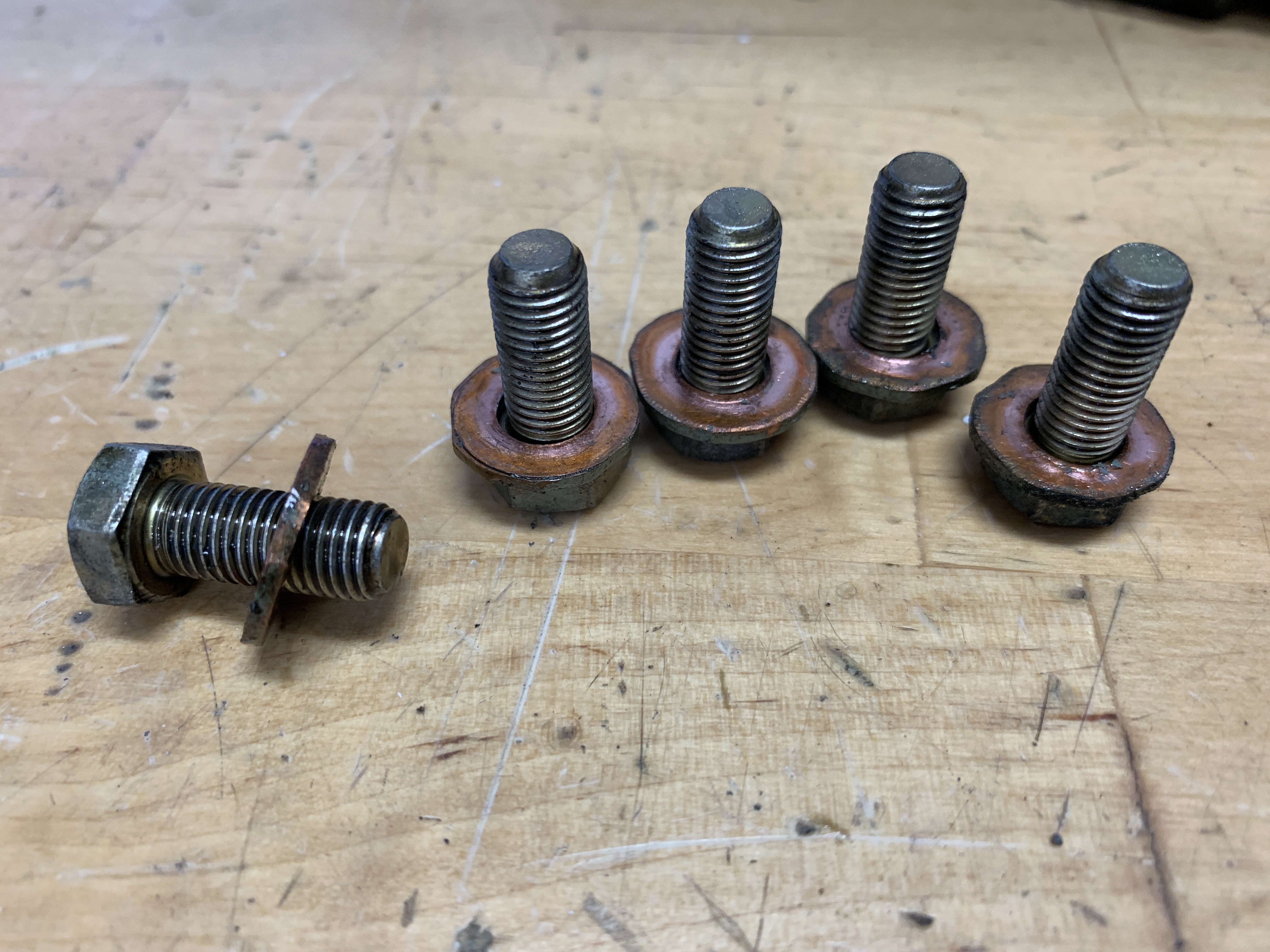
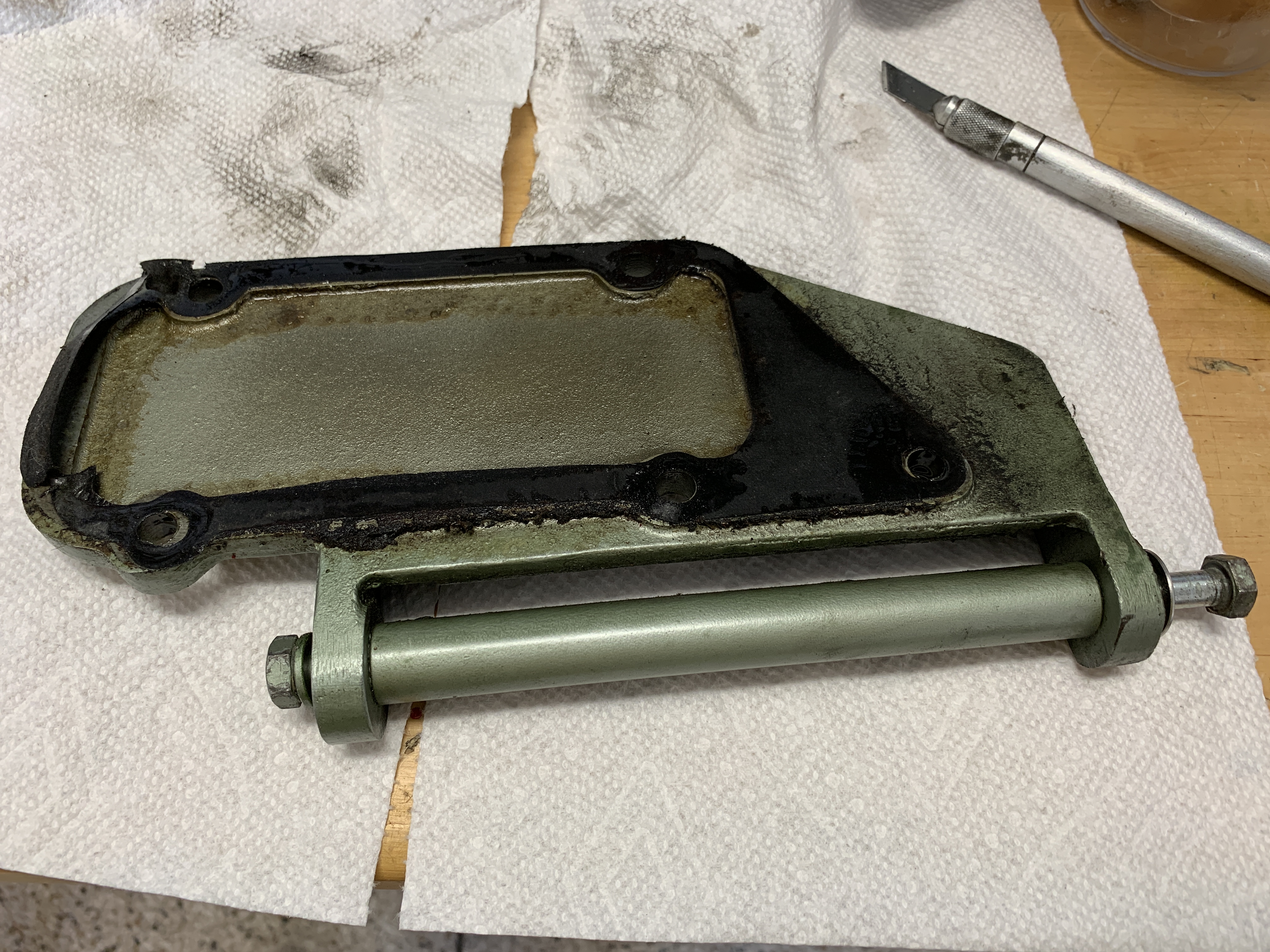
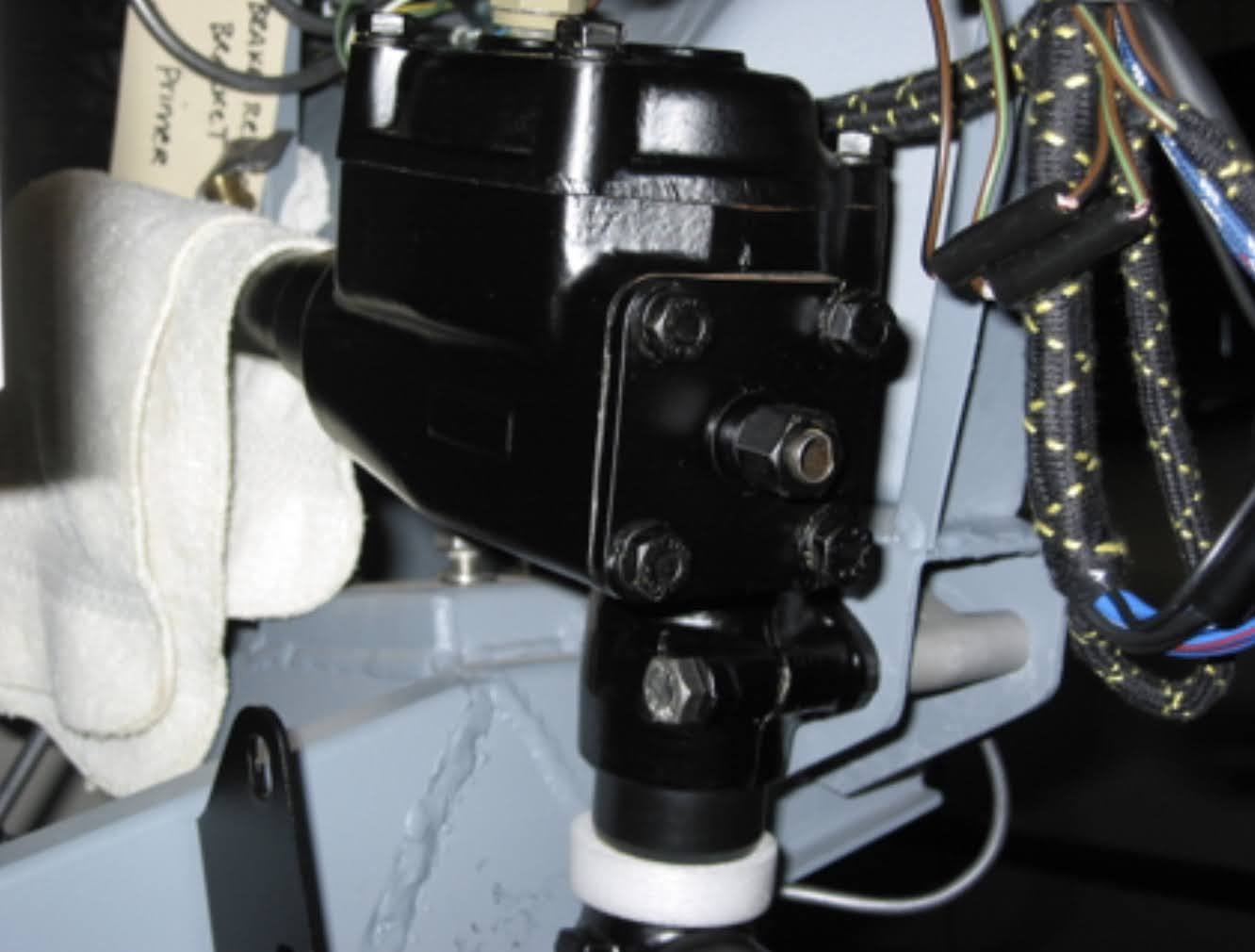
Once the Extension was out of the way, I then had access to the to the slave cylinder! The slave cylinder is bolted to the gearbox with two 3/8”-16 x 1” (course thread) bolts with flat and split washers.

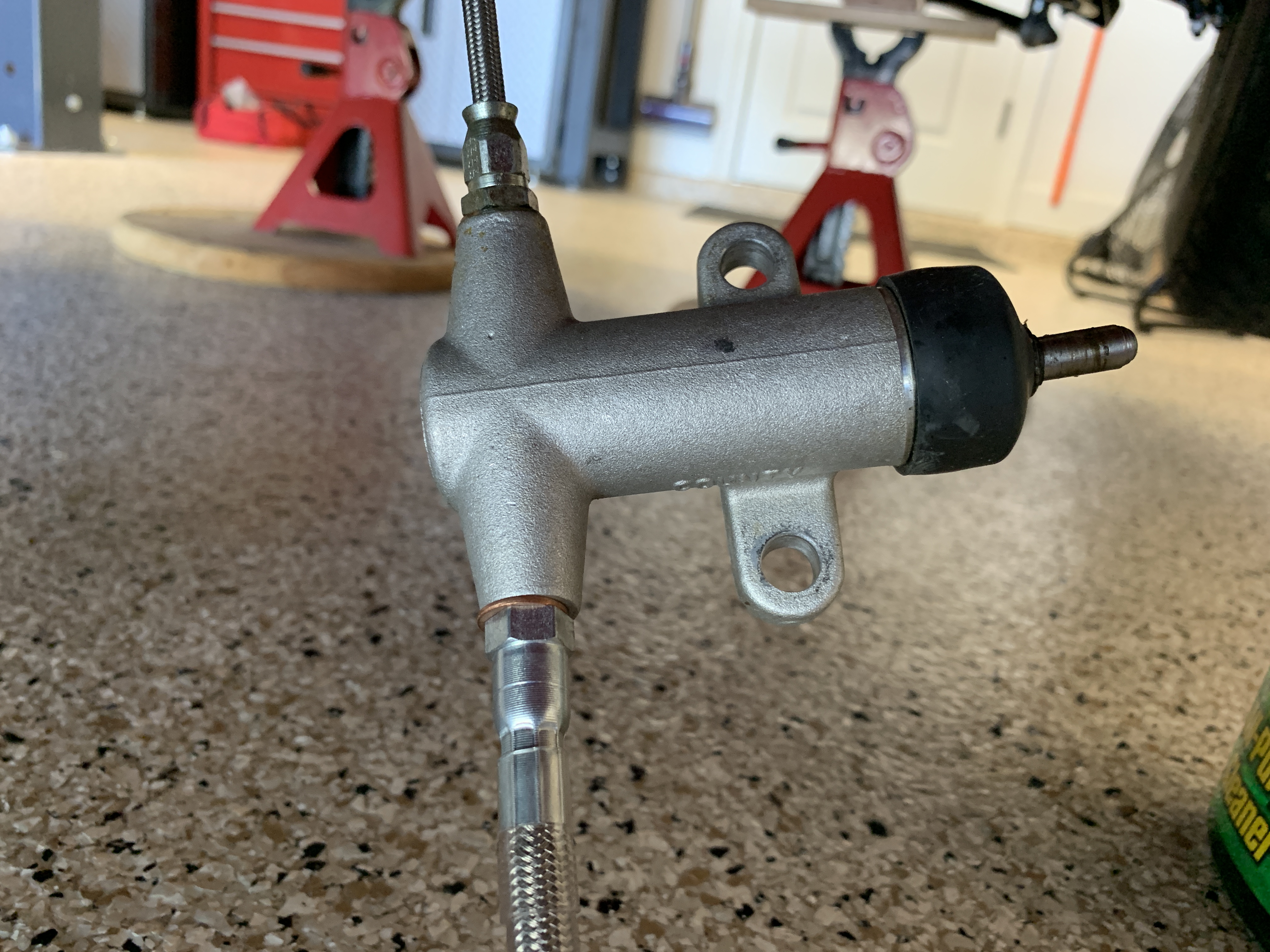
Slave Cylinder Bleeder Hose Fitting

I then removed the slave cylinder. Unfortunately, it is necessary to get to the bleeder hose that I want to remove (Dennis Welch) and to install the Ol Phartz bleeder cable. The slave cylinder is bolted to the gearbox with two 3/8”-16 x 1” (course thread) bolts with flat and split washers. 

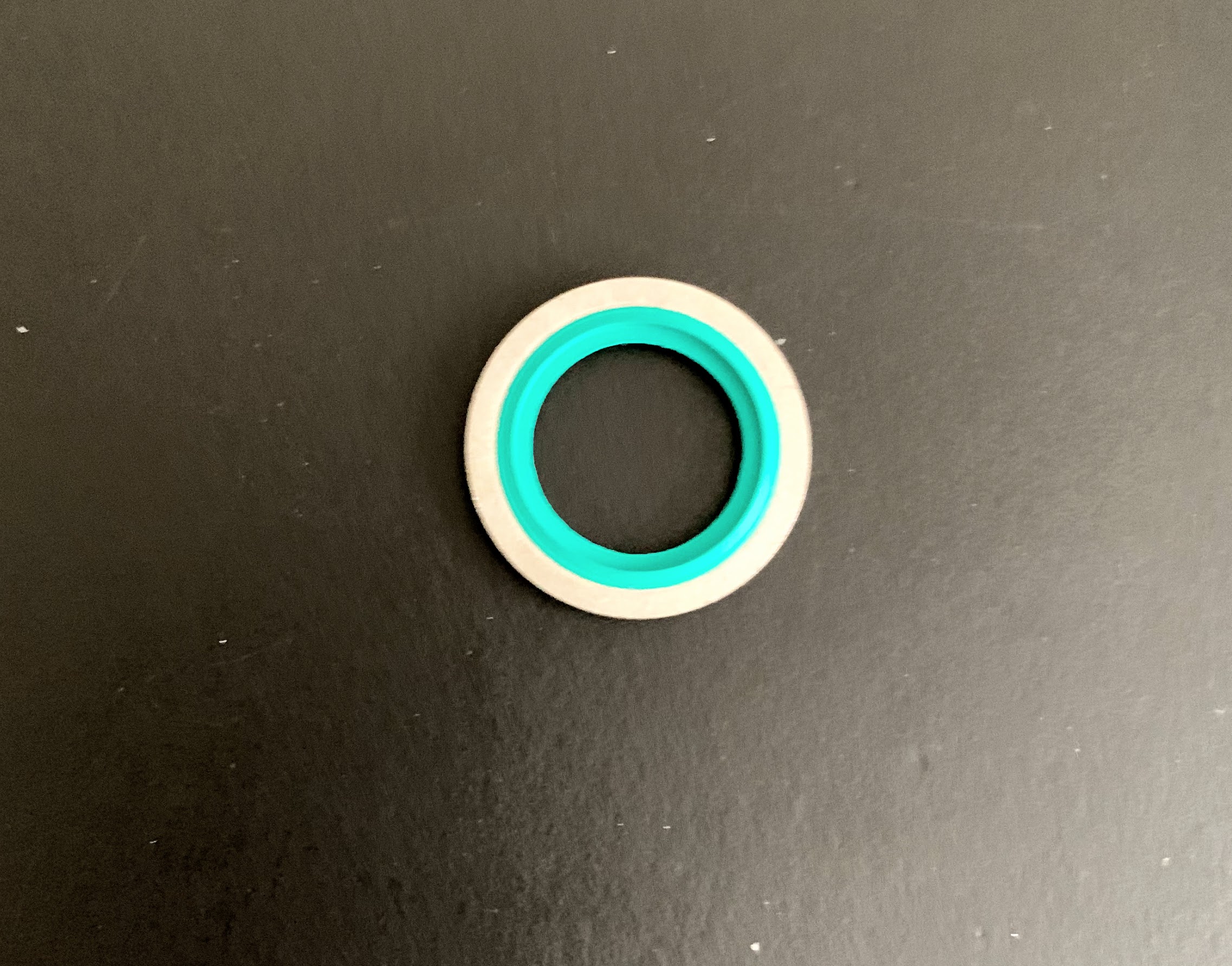
After removing the DW bleeder hose, I installed the OP hose being sure to place the supplied copper crush washer over the end of the hose fitting.

Slave Cylinder with Supply and Bleeder Hoses

I then reinstalled the slave cylinder and routed the Ol Phartz cable up to the top of the gearbox (though the routing is not shown in this image).

I decided to reuse the slave cylinder that was on the car. It had been installed in 2014. It was not showing any signs of leakage, but you never know when that might occur. My thinking was that if the slave cylinder leaks it will only leak onto the floor – not nice red paint! Only time will tell how long it lasts.

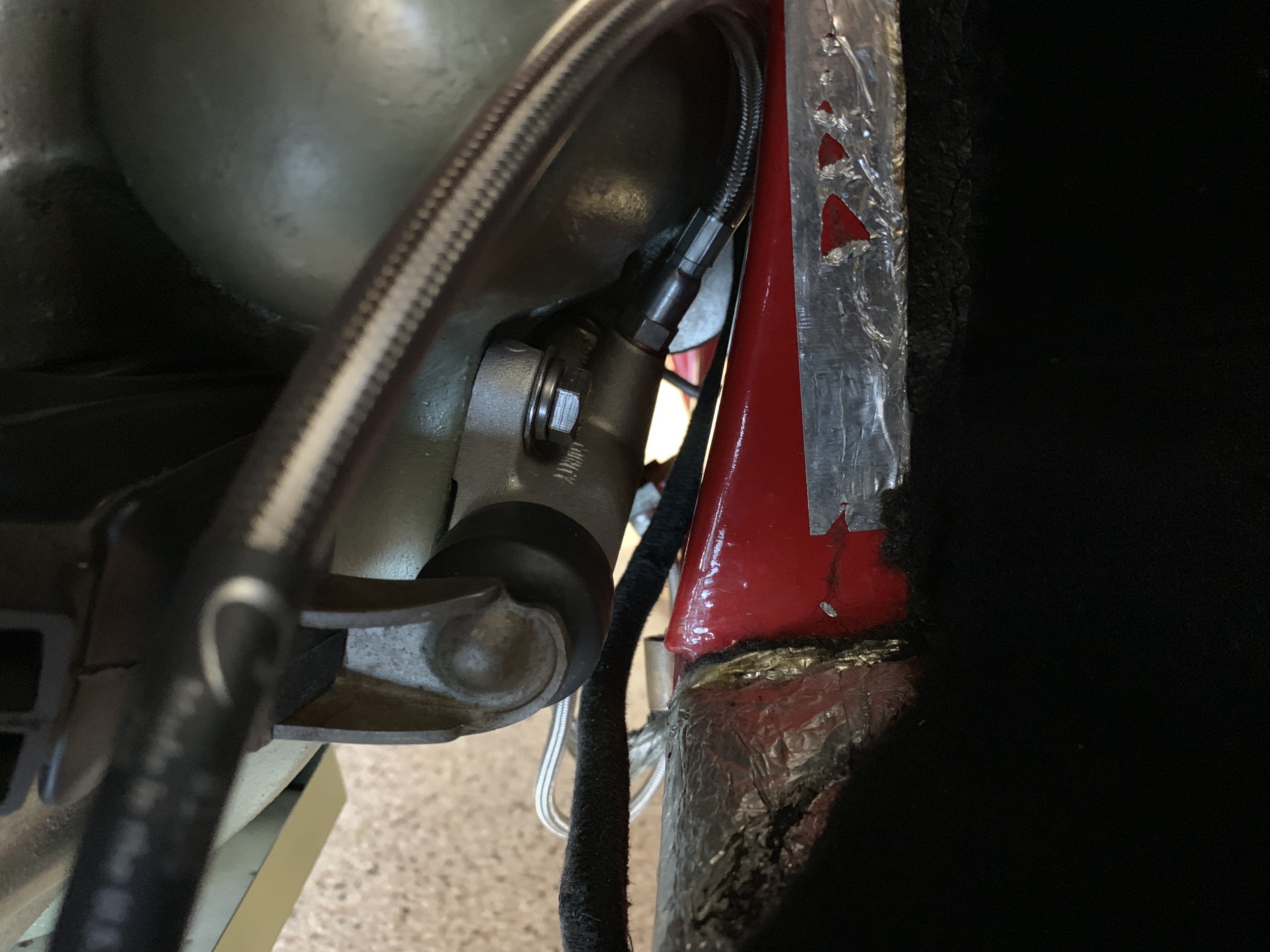
Slave Cylinder Reinstalled

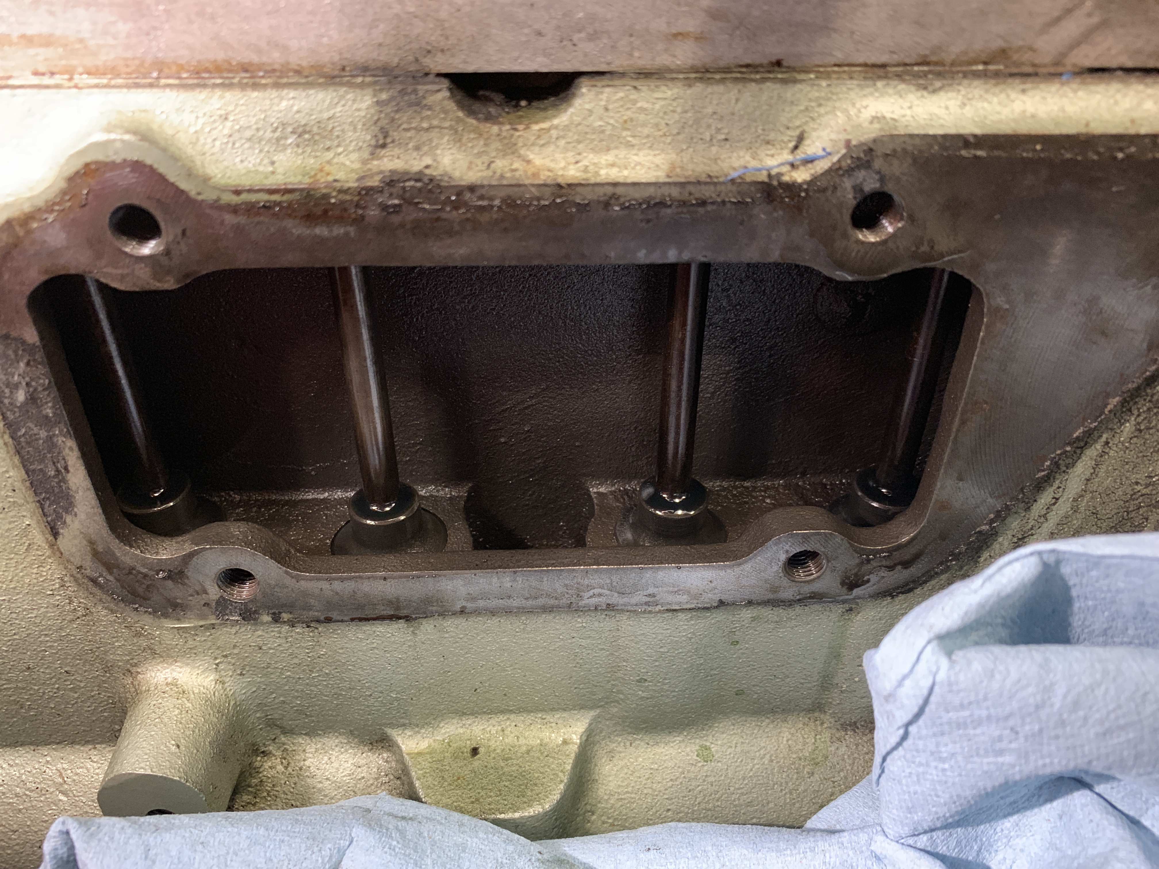
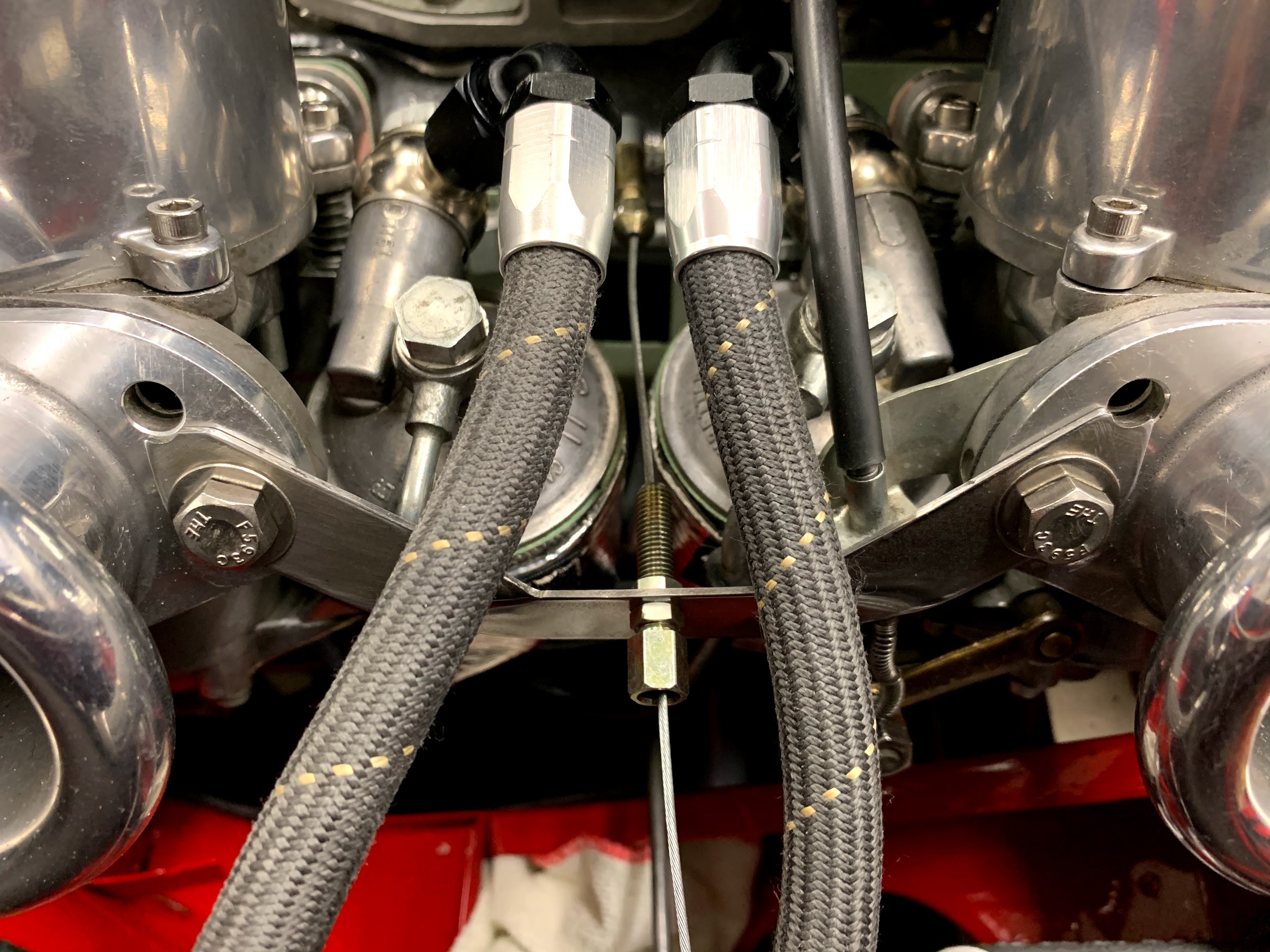
It was then time to finally move to the removal of the clutch master cylinder. In the photo below the clutch master cylinder is closest to the bottom of the image. You can see that I had some paint damage when the brake master failed in 2014. Fortunately, this time I caught the problem before any damage occurred. 
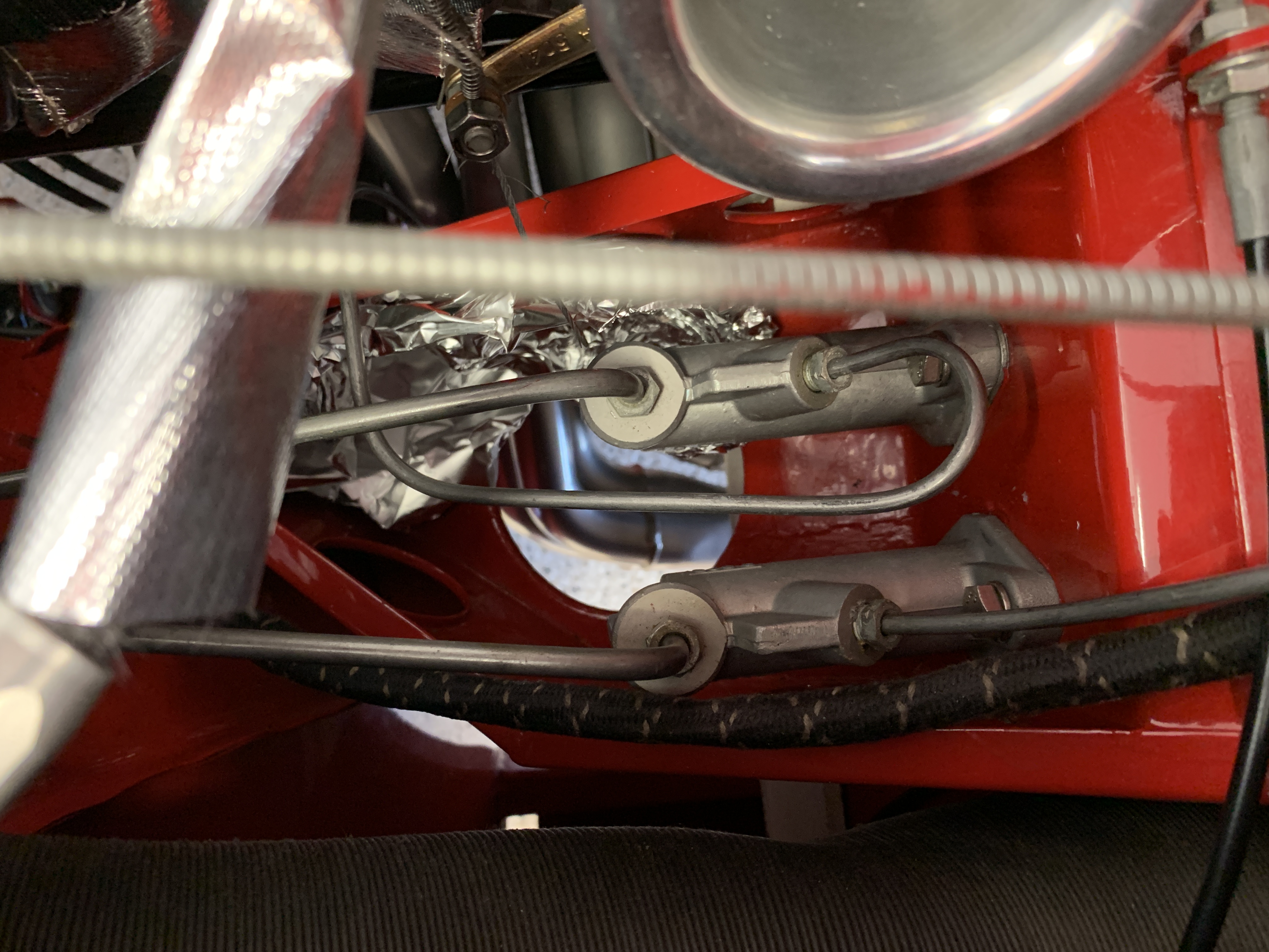
Master Cylinders

That big hole in the diagonal firewall brace (see above) provides nice access to the lower mounting bolts for both master cylinders. One can get below the car and with a short extension on a ratchet with a 1/2″ socket loosen and remove the bolts. I removed the lower bolt and split washer for the clutch master cylinder. I then loosened but did not remove the upper bolt. 

There is some tension on the hard line fittings from both the reservoir and the supply pipe that runs along the firewall ultimately connecting with the stainless steel hose to the slave cylinder. Unless the pipe fittings are properly aligned with their home, it is VERY EASY to cross thread the mounting points in the master cylinder. The pipe fittings are steel while the masters are soft aluminum!

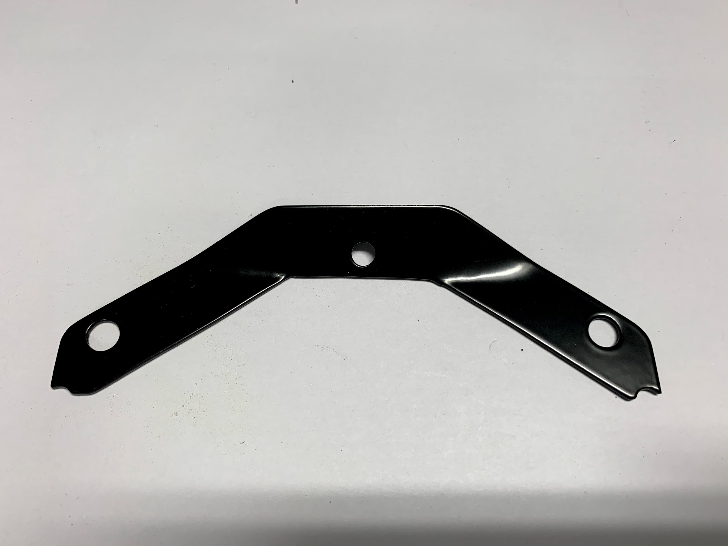
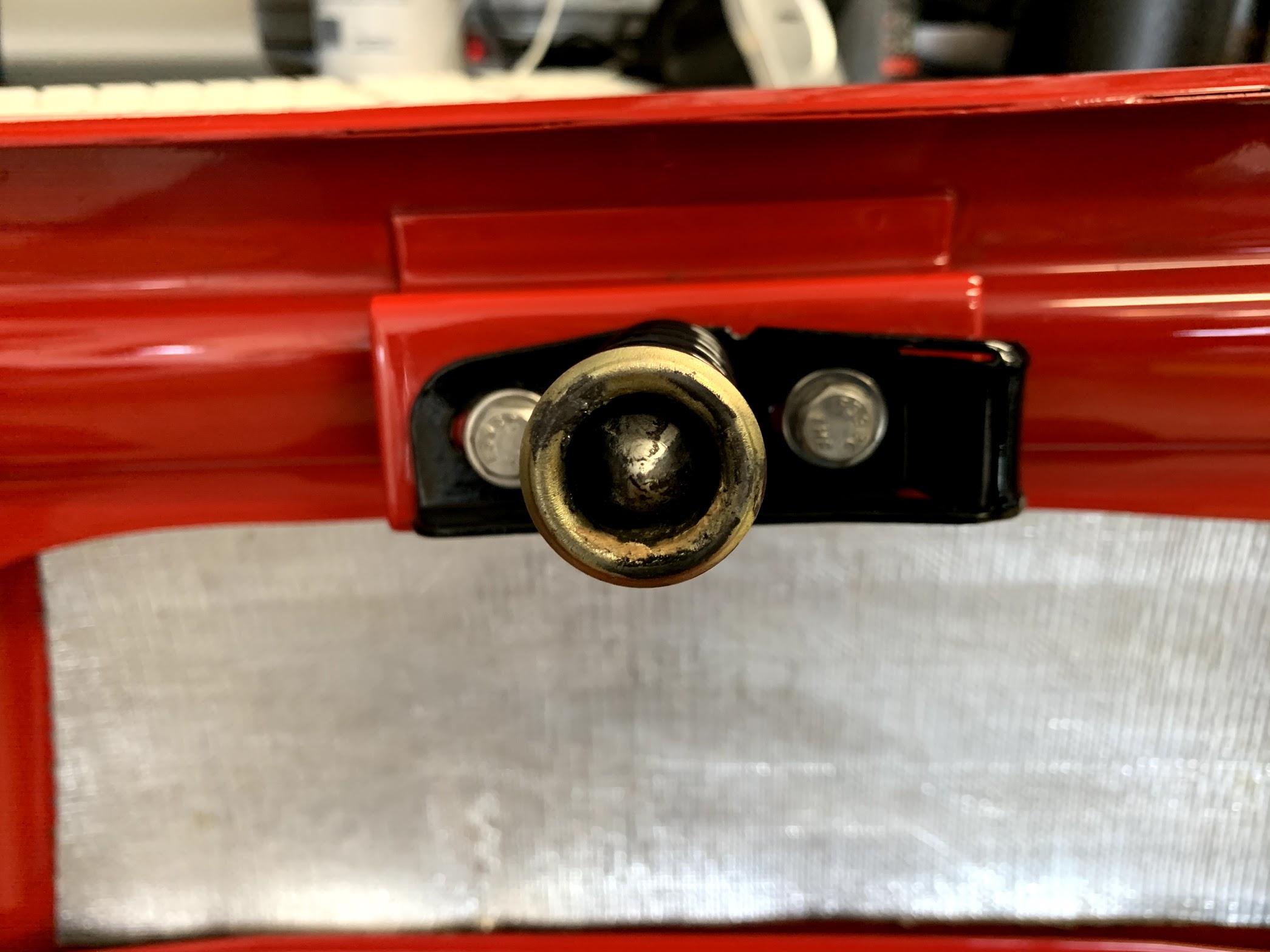
Because of this I like to relieve as much pressure as possible when removing and installing the pipe fittings. To do this I first removed the securing clip on the LH wheel arch:

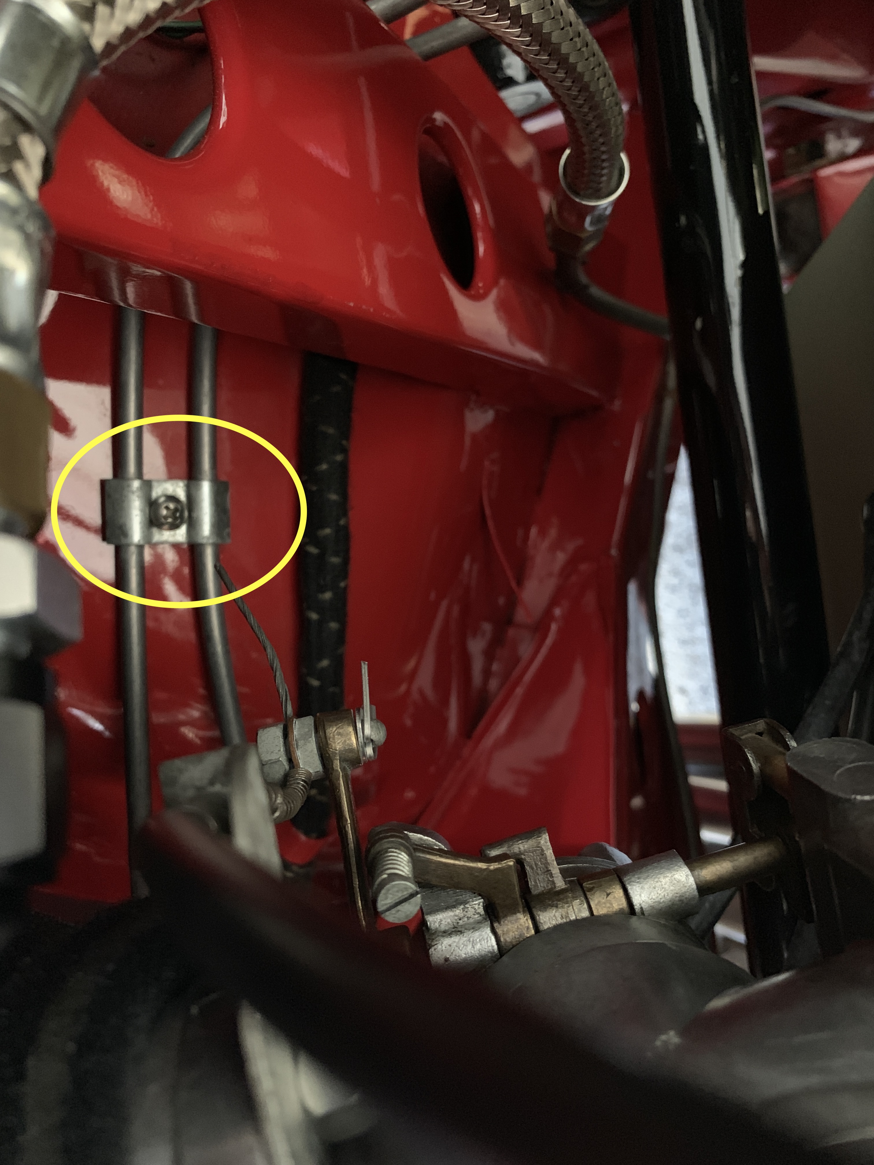
Fluid Pipes Retaining Clip

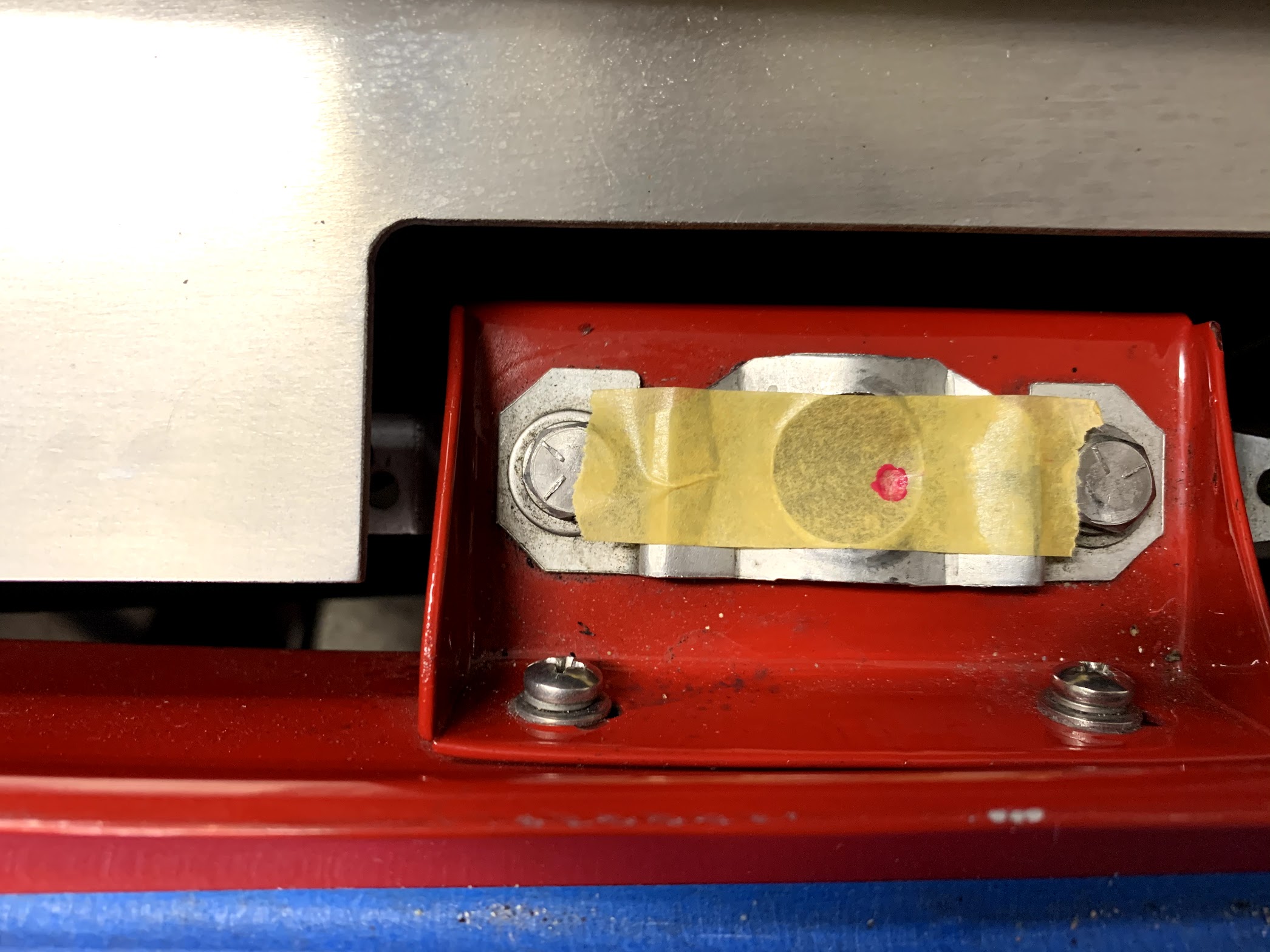
After siphoning out the fluid from the brake side of the reservoir, I removed the nut (circled in yellow below) securing the reservoir canister to its mounting clip. All tension is then removed and it becomes quite easy to loosen and tighten the pipe fittings to the masters.

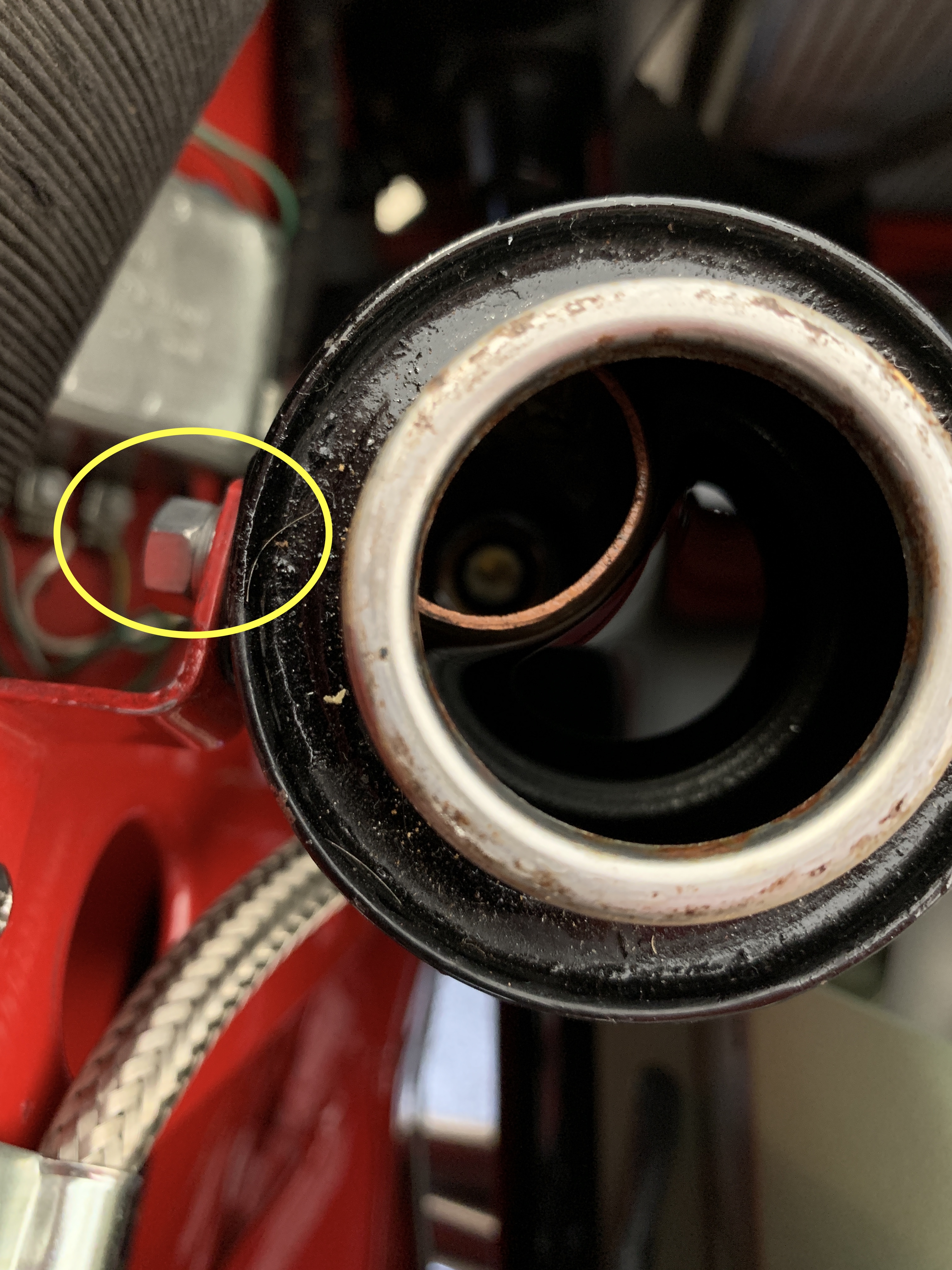
Reservoir Canister Mount

I put a rag under the hydraulic line fitting to the master. I also had some rubber plugs to place over the ends of the pipes, and had a spray bottle of water ready to rinse off any fluid that will surely spill. I disconnected the pipes without incident and after placing the plugs over the pipe ends I put both ends in a plastic bag for extra protection – as it turned out this extra level of protection was not needed. 

Protection from fluid drainage

I then removed the cotter pin at the clutch pedal from the master cylinder push rod fork and clevis pin. The head of the clevis pin was toward the center of the car. After freeing the pedal from the push rod I completely loosened and then removed the top bolt on the master. The master cylinder could then be pulled through the opening in firewall/pedal box and carefully removed to avoid spilling fluid.

To install the new master cylinder I first had to remove the push rod from the old cylinder which was accomplished with some circlip pliers, and remove the threaded push rod that was supplied with the new Girling master cylinders. The original push rod was then installed on the new masters.

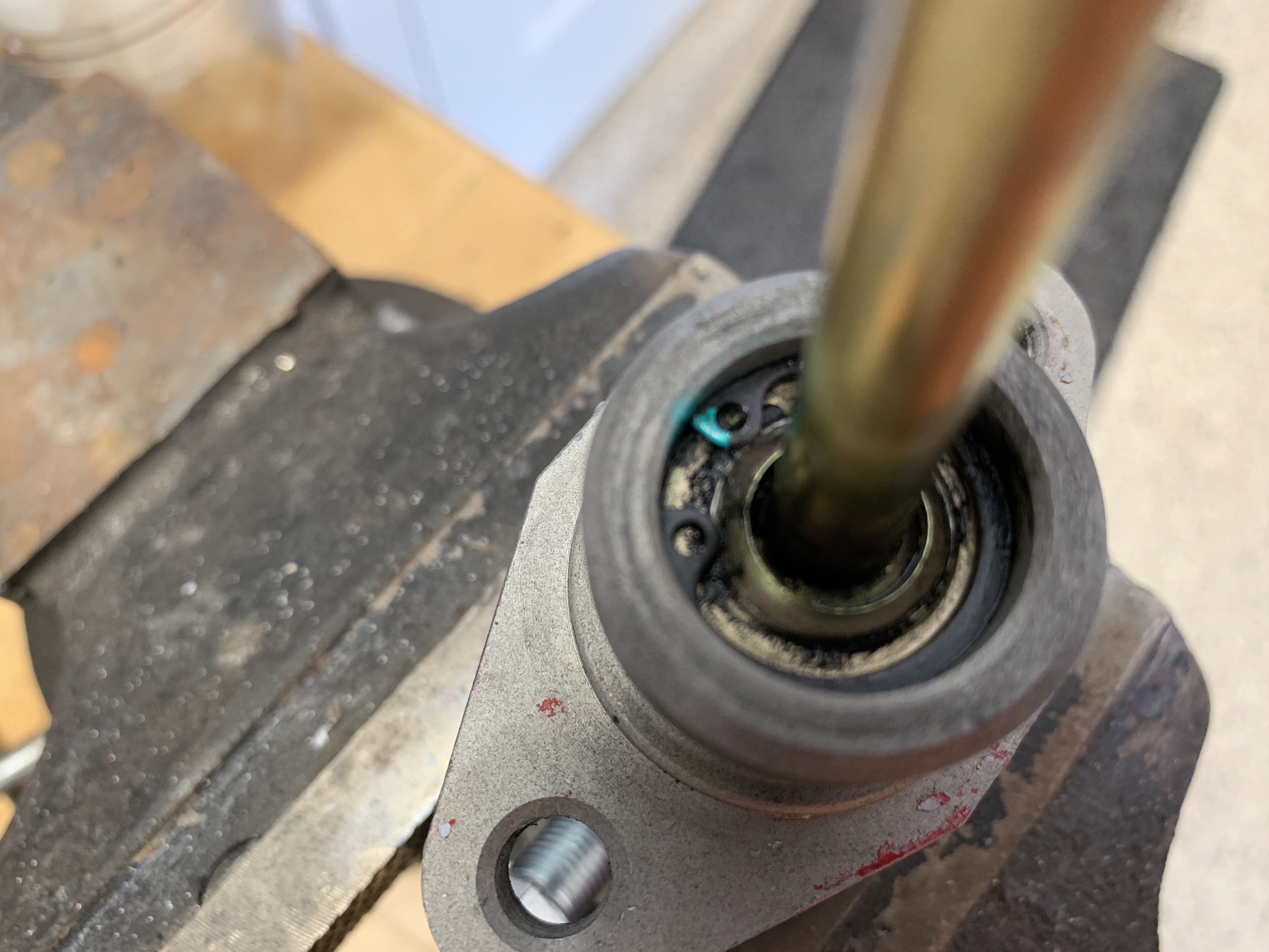
Push Rod Retaining Circlip

I then installed the new clutch master cylinder into the car. With the master against the firewall I inserted the upper mounting bolt through the sleeve of the master but left it loose. I discovered that you need to put this bolt in place BEFORE you install the clutch supply pipe fitting into the master cylinder, because once the pipe fitting is mounted one cannot get enough clearance to install the bolt. I then screwed the clutch supply pipe fitting into the rear port of the master cylinder. This was followed by the installation of the pipe from the reservoir to the front port of the master

With both pipes in place on the clutch master I then got under the car, put my hand up through the frame brace hole, and threaded the second bolt to the lower fixing point. It helps to center the master on the firewall/pedal box hole with a tapered punch. Using the ratchet and 1/2″ socket I fully tightened the lower bolt. Returning to the top of the car, I fully tightened the upper mounting bolt for the master cylinder.

One then needs to stand on one’s head in the interior, sliding upside down under the steering wheel to reach the pedals. The pedal mount is then lined up with the push rod fork, the clevis pin is inserted, and a new cotter pin is installed.

That completes the installation of the new clutch master cylinder. It is now time to complete the same process for the brake master cylinder. The very same process was followed.

Bleeding the system

Once the new brake master was installed in the car, bleeding the clutch and brake systems was undertaken.

I bled the clutch system first. I filled the fluid reservoir with Dot 4 brake fluid. I typically use Castrol but it was not immediately available so I used a Valvoline product instead. I then opened the bleeder on the clutch bleeder hose and attached my Sealey Syringe and pulled fluid, and air, through the piping and hoses. I then closed the bleeder valve and  turned to the traditional two person pedal down, pedal up process. Opening the bleeder to push the pedal down and then closing the bleeder to let the pedal up. This prevents air from entering the system. This process resulted in the evacuation of some more air. Pedal movement actuated the throw out arm for the clutch as it should.

I then routed the bleeder hose to where it will be permanently mounted. In the future I will bleed from this location.

Ol Phartz Clutch Bleeder Hose

I then used the syringe on the bleeder valves of each of the four wheel calipers (I have 4 wheel disc brakes). I began with the LH rear, then the RH rear, then the LH front and finally the RH front. After sucking out fluid and most of the air, like the clutch, I turned to the traditional two person pedal down, pedal up process. This resulted in a pretty firm brake pedal.

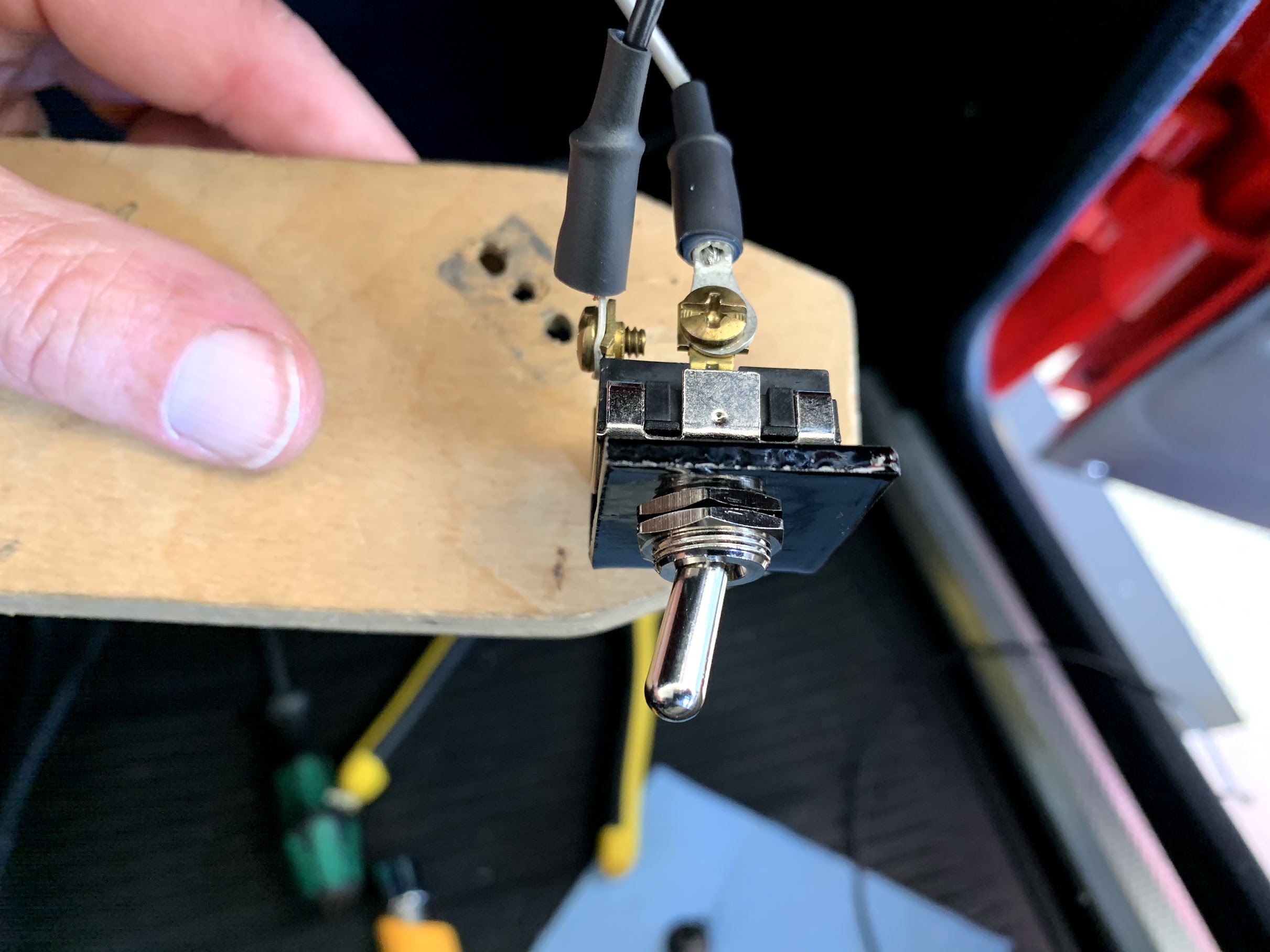
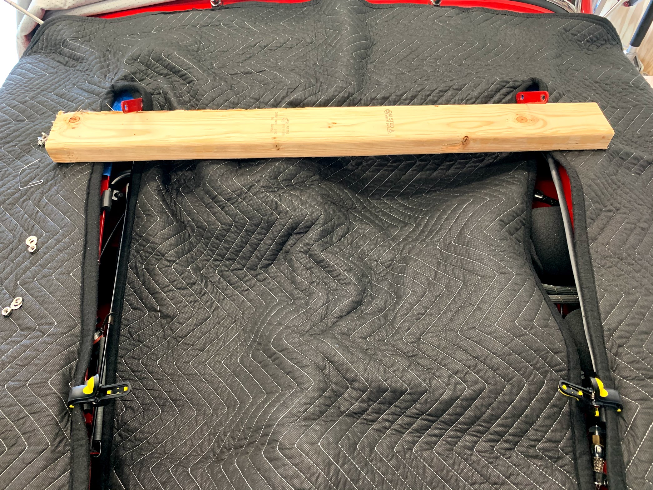
As a final step I used a technique suggested on the British Car Forum. One depresses the brake pedal and leaves it overnight. Mysteriously the process seems to firm-up the pedal beyond what one accomplishes through traditional bleeding.While this image is not of my car, I used precisely this arrangement and it worked beautifully!

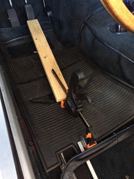
Brake bleeding with Pedal Pressure


I found that using the syringe to draw fluid through both systems made bench bleeding the masters unnecessary. I did not bench bleed (in the car or on the bench) the masters and I have a perfectly functioning clutch and a nice brake pedal feel. Happy with the results, and hopefully leak free for at least another five or six years! As a final step, I re-fastened the double pipe clip for the reservoir pipes to the left hand fender valance.


Charlie Hart Fuse Panel

Fellow Healey enthusiast, Charlie Hart has come up with several “customizations” over the years to “improve” on the original Austin-Healey design. He then makes these available to the Healey community. One of those items is a fuse panel that mounts to the firewall in the same manner and place as the original. The panel has seven fuses with a total of fourteen terminals. Two of these are unswitched – direct feed from battery and twelve are switched – hot when the ignition is turned on.

This is the original fuse panel. It was very crowded with the electrical enhancements I have on my car – cruise control, extra fresh air blower, extra under dash three fuse fuse panel, intermittent wiper control, beeper for turn signals and a sound system. If I had a failure in one of these circuits it would be difficult to assess given the small number of fused circuits.

Original Fuse Block

Charlie’s fuse panel is comprised of a number of individual fuse blocks that are screwed into a flat piece of pvc, and came complete with wire connectors and a sample wiring diagram based on an original unmolested car.

Charlie Hart Fuse Panel

This is a photo of the panel installed with connections made. I still had to double load some of the connection points but circuit segregation is much better than it was before!

Charlie Hart Fuse Panel Installed

This is an image of the actual wiring to the fuse panel in the Bloody Beast:

Rose Fuse Panel 9-3-2019


Rear Main Oil Leak – Diaper Fix

Healeys, as well as most other British cars of the period, like to leave their mark! That is, one can expect oil leaks on their garage floor or driveway. When I rebuilt my engine ten plus years ago, I installed an improved rear main seal designed and sold by Dennis Welch Motorsports. Disappointingly, it failed to correct the oil leak problem, although to be fair, it might be worse had I not made the modification.

If you can’t get rid of a leak, then perhaps you can at least do something to keep the leak from hitting the floor. Jim Shope came up with a plan for a little drain pan that basically serves as a diaper for the Healey. The pan catches the slow drips, and every month or so the pan can be wiped out. The following images illustrate the template and measurement for making the drain pan – thanks, Jim!

The Template is 9″ x 7.5″. I used aluminum but steel sheet could also be used. After making the cuts with some tin snips and drilling the two holes, I used a small sheet metal brake to form the box. I then used JB Weld to seal the edges of the box.

Oil Drip Pan Template

Oil Drip Pan Template Mounting Hole Dimensions

Oil Drip Pan Cut Out Ready for Bending

I used some engine green spray paint available from Moss Motors to paint my little diaper. I plan to use a small piece of Pig Mat (Oil absorbent pad) in the pan to collect the oil. Hopefully, I can then just switch out the the dirty pad for a clean one without having to remove the pan. We will see.

Oil Drip Pan Painted and Installed

Main Seal Diaper in place

Cylinder Block, Front Cover, Oil Leak Repair

The front cover has leaked oil for some time. In this post, I describe the process to remove the cover, replace the gasket and then reinstall the cover to the cylinder block. This process involves removing the alternator. When I restored my BT7 I “upgraded” from the original dynamo, or generator, to an alternator. At the time, I purchased a “kit” including the mounting brackets for the alternator. The kit was designed to use an easily obtained Delco Alternator: Delco SI 10 alternator with an internal regulator. (about a 72-on Chev). NAPA part # 2134011 and a NAPA Part # VRC 148 plug.

Instructions for the installation of the alternator are provided in the Electrical System entry of this Big Healey Valvechatter website. I will not repeat that information in this Blog entry.

The first step in this process is to turn off battery power with the switch in the boot. I then clipped the plastic tie I had used to secure the radiator overflow hose to the rear arm of the alternator bracket.

Alternator Slide Brackets Coolant Hose Tie

I then removed the bracket mounting bolt and nyclock nut on the swing bracket. The bolt is stainless and it is a 3/8″-24 x 3″ with flat washers and the nylock nut.

Alternator Bracket Mounting Bolt Fastener

The alternator wiring white pigtail connector with white and red wires was disconnected from the alternator body. I also disconnected the red wire and the heavy gauge brown wire from the screw post on the back of the alternator. The brown wire is routed to the alternator from the starter solenoid. The nut on the alternator wiring post is 10mm.

Alternator Wiring

Alternator Wiring

I then loosened and removed the 5/16″-18 x 1 3/4″ bolt with flat and lock washers that is inserted through the mounting ear of the alternator and into the spacer on the cylinder side front cover. Once removed the alternator can then be removed from the car.

Delco Alternator Removed

The five mounting bolts that secure the front cover to the cylinder block are now accessible. In the image below, oil residue from the leaking cover can be seen.

Front Cover Cylinder Side AEC689

The cover is removed by loosening and removing the five mounting bolts and copper flat washers.

Cover to Cranckcase Screw HNS0506

The next task was to clean-up the cover by removing the old gasket and degreasing the part. I took advantage of the opportunity and repainted the cover prior to reinstallation.

Removal of Cover Gasket AEC313

This is the freshly painted cover and the new paper gasket AEC 313.

Front Cover for Cylinder Side with new gasket and Custom Alternator Spacer

Before installing on the block I carefully cleaned the cylinder block and particularly the mounting flange for the cover.

Cleaning gasket residue from cylinder block

I smeared a light coating of Permatex #2 Form-A-Gasket Sealant on the gasket and placed it on the cover, using the mounting bolts to center the gasket on the cover. I then smeared the other side of the gasket and then mounted the cover to the cylinder block using the five bolts and washers previously removed.

Front Cover Cylinder Side Reinstalled

While the alternator on the car was functioning just fine I decided to go ahead and install a new (rebuilt) alternator in its place. one must take care to ensure that the fan belt is properly located on the crank, water pump and alternator pulleys. With the alternator held in place the front mounting bolt can be reinstalled through the ear of the alternator, and the cover and then screwed into the threaded spacer tube.

Alternator Mounting Ear

The 3″ bolt was then inserted through the swing bracket and the “wide” mounting ear of the alternator and tightened providing approximately a 1″ deflection of the fan belt.

Finally, all electrical connections were made and after a final check the boot master switch was turned to the “on” position.

The car was then test driven with the charging light on the speedometer switching off as the car accelerated.

One more job complete!

Lucas PL700 Headlight Conversion

I have always liked the looks of the Lucas Tri-bar PL700 headlights. Unless one can find some new old stock units on eBay or from an individual seller the originals are hard to locate. However, reproduction vintage lights are available and come with a modern twist in that they utilize H4 bulbs, giving you a vintage headlight look with modern reliability and power. The lights I ordered from NOS Locators come with 12v P43t (9003) H4 bulbs: 60 watt high, 55 watt low. Flosser brand Halogen Bulbs and the bulbs are made in Germany.

This is a link to an article on the technical specifications and general information on the original Lucas PL700s:PL700

Lucas PL700 Reproduction Headlights

Headlamps

To install the new lights the first thing to do is to remove the Phillips head sheet metal screw (2) holding the headlight rim assembly (1). This screw is located to the right of center at the bottom of the ring.

Then remove the rubber dust excluder (4) and the three Phillips head sheet metal screws holding the outside light unit retaining plate (5).

Rubber Dust Excluder

Headlight with light unit outside retaining plate in place

Three screws for outside light unit retaining plate

The retaining ring can then be withdrawn providing access to the bulb and it’s electrical connector.

Retaining plate removed to access headlight

This is a photo of the new headlight with bulb to be installed. A rubber boot to cover the electrical connection was also provided.

Lucas PL700 Headlight and Bulb Rear View

Connecting the new headlight is all “plug and play.” It is just a matter of unplugging the old sealed beam headlight and plugging the three-prong plug into the female plug on the wiring harness.

Then it is simply a matter of holding the PL700 in place while resecuring the light unit retaining plate with the three short Phillips head self tapping screws and replacing the rubber dust excluder. It requires a little finagling but one then slips the tab on the top of the rim assembly over the retaining plate and replacing the Phillips head screw (2) at the bottom of the rim by screwing it into the nut for screw (3). 

Other than a final check of the alignment of the headlamp light beams and adjusting with the spring loaded screws, the job is complete. It is a good look!

Lucas PL700 reproduction headlamps installed

Lucas PL700s ready for use


Fuel Delivery Modification and Ram Pipes 

This project actually began back in November and took me till Spring to complete! I was inspired by Doug Escriva’s beautiful engine bay on his even more beautiful Healey racer:

Doug Escriva’s Racer

Doug Escriva’s Engine

I especially liked Doug’s fuel delivery system to the carbs. Of course, Doug’s car is a tri-carb while mine has only two HD8 SUs. I was never fond of the original fuel delivery design in which the fuel hose fed to the front carb banjo with a second feed off that banjo to the rear carb via a 2″ piece of hose. I also liked the idea of getting rid of the required fuel hose screw clamps and changing to AN fittings. Finally, I am a sucker for the look of the air horns on the SUs. Since I live in Florida where it is sandy, I will use some socks over the horns for normal driving to protect the intake ingesting some unwanted silica. While these modifications appeared easy to accomplish, as it turned out it was quite a chore to find the necessary fittings. Hence the long elapsed time from concept to completion. 

Before getting into the components required for the new system, I also need to mention that my Healey friend, Randy Forbes, who is now geographically close since we have relocated to Florida, was also a big help in making some modifications to the components.

These two photos show the new fuel lines, the fuel fittings and the “Y” Fuel Block installed:

Modified Fuel Delivery System and Ram Pipes

Modified Fuel Delivery System with Y Fuel Block

Modified Fuel Delivery Hose and Fittings

I replaced the original brass banjos on each carb with Steel 16mm M16 5/8″ 6AN Banjo Adapters with short necks, part #C1116-0062. These were difficult to find but I ultimately located them on EBay. The seller’s name was smartturboisme.

Banjo Adapter 16mm -6AN C1116-0062 EBAY

These were slightly wider than the original brass banjos requiring new banjo bolts. These were also difficult to source. I eventually located these 3/8″ BSP banjo bolts from AgriStore USA. They were 1 1/2″ long with four fuel flow holes. They were slightly too long to fit snuggly in the SU float bowl caps so Randy Forbes cut them down slightly. While the threaded portion of the bolts fit through the new banjos, the grip portion of the bolts would not so Randy also took a few thousands off the grips.

3/8 BSP Banjo Bolt

I purchased Viton sealing washers for the banjos and the bolts. These were sold by Hydraulic Fittings, part #9500-06V Bonded Seal, 3/8″BSPP (Viton). 2 were required for each carburetor.

3/8 BSPP Viton Seal Washer

I installed a new, as original, petroflex fuel line which connects to the fuel hard line running from the fuel pump to the engine bay. This hose is part #FUL062 from Healey Surgeons. A 90 degree 811 Aluminum hose end #3481-06 was then screwed into to the upper end of the petroflex fuel line. The hose ends were sourced from Pegasus Auto Racing Supplies

Aluminum Hose Ends

A short piece of racing fuel hose, 910 PTFE Lined Aramid Braided Lightweight -6 from Pegasus was used to connect the 90 degree fitting from the petroflex hose to a straight fitting which then screwed into a “Y” fuel block.

910 PTFE Lined Aramid Braided Lightweight Racing Hose

The fuel block has a single inlet and two outlets, all 6AN. The fuel block was made by Russell and sourced from Jegs part #799-650430.

Russell Billet Aluminum Y-Block -6 AN Male Single Inlet

One straight and one 45 degree aluminum hose end was used to connect the outlets of the fuel block to two 90 degree aluminum hose ends at each carb banjo. All of the fittings and hose connections proved to be tight and leak free when tested. I am very pleased with the functional and esthetic enhancement to the stock fuel delivery system. 

I purchased the 2″ polished aluminum ram pipes from Doug Escriva as well as pair of ITG Megaflow JSC-12 Air Socks.

ITG JSC-12 Megaflow Air Socks

Electric Pusher Fan Installation


While my car usually runs at a reasonable operating temperature, I do get a little worried about the potential for getting stuck in traffic, and now that we are in southwest Florida with routine summer temperatures often in excess of ninety degrees overheating could occur.

I have already applied all of the typical tricks for improved engine cooling: aluminum high capacity radiator, baffling to direct the air to the radiator core when the car is moving, shroud around the mechanical fan, improved fan, clean engine internals and etc.

While I do not need an electrical pusher fan in normal operating conditions, I think an electrical fan, operated by a toggle switch in the interior, may provide a good solution for those situations where I find myself sitting in traffic, or in a local parade. One could install a temperature sensitive switch to automatically turn the fan on/off at prescribed temperatures, but I have decided that I will just stick with a simple on/off toggle switch. I really hope that I will rarely need to use the electric pusher fan!

Some others on the various Healey Forums have suggested that an electrical fan may actually block the flow of air through the radiator that could result in higher running temperatures – I hope that will not be the case.

FAN SELECTION

The first step in this little project is the selection of the fan to be used. Factors to be considered include the width, height, and depth of the fan, the amperage draw (not much of a concern given that the Beast has an alternator installed rather than the original generator), and the fan’s output measured in CFMs or cubic feet per minute.

I am somewhat restricted regarding the size of the fan I will use. My aluminum radiator has fan mounting clips already welded to the sides of the radiator and I want to use them for fan mounting.

Aluminum Radiator with Fan Mounting Brackets

Consequently, a 12” circumference fan is the largest I can use. The “X” body brace in front of the radiator restricts the depth of the fan. A quick measure produced a maximum depth of 3.” Given these parameters I searched the internet for an appropriate solution and decided on a Maradyne product from Summit Racing. 

The Maradyne M123K has the following specs: 

Brand:  Maradyne High Performance Fans

Manufacturer’s Part Number: M123K

Summit Racing Part Number: MAR-M123K    UPC: 810349010123

Puller: Yes      Pusher: Yes

Fan Diameter (in):  12.000 in.

Fan CFM Range:  1,100-1,199

Maximum Fan CFM:  1,155 cfm

Height (in):  13.230 in.

Width (in):  12.520 in.

Thickness (in):  2.610 in.

Number of Blades:  10 blades

Blade Material:  Plastic Blade Color:   Black

Shroud Color:  Black     Shroud Material: Plastic

Amp Draw:   7.20 amps

Mounting Brackets Included:  Yes

Mounting Hardware Included:  No

Notes:  130 Watt motor.

Maradyne Fan Image

PUSHER VERSUS PULLER

This particular fan can be a pusher or a puller. As shipped it is a puller so the first step is to reverse the fan. To do so one lift the safety catch over the shaft end and carefully pushes the clip off the motor shaft.

Maradyne Fan

The fan instructions then indicate with another person, carefully pull the blade off the motor shaft. Flip the blade, then place back on the motor shaft by lining up the groove on the blade hub with the drive pin on the motor shaft.

Then replace the clip by pushing the clip into the groove on the motor shaft. Ensure safety catch snaps over the motor shaft. Pusher configuration is now complete.

In the pusher configuration the blue wire to the motor is the negative connection and the black wire to the motor is the positive connection.

Maradyne Fan Rotation Diagram

I made the job of creating brackets linking the fan to each of the four mounting tabs on the radiator a bit harder than it needed to be because I did it with the radiator mounted in the car. I really didn’t want to drain coolant and pull the radiator out to make the brackets on the bench. Consequently, some trial and error was involved, but I got there!

Having the car on the garage lift made the task simpler than it would otherwise be. I cut the brackets out of some off-the-shelf steel sheet purchased at the hardware store, and after checking the fit I painted the brackets black for rust protection. I then installed the fan using four 1/4“-28 x 1/2” and four 1/4”-28 x 3/4” stainless bolts and nylock nuts.

Electric Fan Mounting Brackets

Maradyne supplies four rubber cushions or feet that hold the fan away from the radiator cooling fins:

Rubber Cushion Spacers

This is a view of the mounted fan from above:

Electric Fan Mounted Top View

And, from below:

Electric Fan Mounted Lower View

This image shows the lower RH bracket attached:

Electric Fan Mounted Lower RH Bracket

WIRING

Once the fan was installed, the next step was to install the wiring required.  Before actually doing any wiring, I turned off the master switch in the boot of the car thereby removing power from the electrical system of the car.I used a Fan Relay Harness sourced from SPAL and followed the wiring schematic provided with the harness.

SPAL Fan Relay Harness

Since I am only using a toggle switch to turn the fan on/off and am not using a temperature controller I followed the dotted line wiring to the switch and skipped the sending unit wiring.

Fan Relay Harness wiring schematic

I used a toggle switch I had in my parts bin for this application.

Toggle Switch

I mounted the relay on the inside of the firewall behind the parcel tray on the passenger side of the car. I wanted to hide the toggle switch from view so after making and painting a little metal bracket for the switch,  I mounted it on the back side of the plywood used to secure the passenger “grab handle.”

Mounted toggle switch bracket

Toggle switch mounted

This made it easy to attach the grey wire from the relay to the toggle switch and I made a black wire for the ground connection from the switch to a screw on the inside of the firewall.

I ran the orange wire to the ignition switch so that the relay would be energized when the ignition switch is in the “on” position. The mounting posts on the ignition switch can get a little crowded so I took advantage of a “terminal splitter” I had in my parts bin that made connecting the wiring much easier.

Terminal splitter

The yellow and red wires from the relay exited the interior through an available rubber grommet on the firewall into the engine compartment. The yellow wire, after splicing in the 30 amp fuse, was then connected to the starter solenoid as a battery power source. 

The red wire followed other wiring down the diagonal RH frame brace to the front of the car where it attached to the fan wiring pigtail. The red wire connects to the black wire on the pigtail, because the wiring was reversed when the fan was converted from a “puller” to a “pusher.” I then made a short black wire to connect to the blue wire on the fan pigtail and attached it to a ground screw near the grille of the car.

I then turned on the master electrical switch in the boot, and turned the key to the “on” position of the ignition switch, and flipped the toggle switch to the fan. I immediately heard the whine of the new fan and I knew I was in business! 

One more Healey task completed!!


Leaking Steering Box

It is not at all uncommon to have a leaking steering box. When I rebuilt my steering box some years ago I filled it with Penrite Gearbox oil – the recommended oil at the time. It is very thick and has to be warmed up to get it to go into the steering box.

My guess is that the rubber seal on the steering shaft needs to be replaced. That is a fairly big job. Others have mentioned that the use of Corn Head Grease, a John Deere product, will greatly reduce, if not eliminate leaks. I decide to give it a try.

One can ever so slightly loosen the four screws on the front of the box (no more than 1/8″) to let the old oil drain out. I am betting that most of mine has already drained out so I decided to just fill the box with the Corn Head grease and see what result I obtained.

I used a very small, needle-type, fitting on my grease gun and pumped away until the box was full. I then turned the steering wheel back and forth a number of times – easier if you get the front end off the ground first – to “settle” the grease. I then pumped some additional grease into the box and wrapped up by re-securing the filler bolt to the box.

The image below shows the rebuilt box when I trial-mounted it in the car when it was in primer. A white foam seal can be seen. This seal is there to keep dust/dirt out of the mechanism. It does not actually help to seal the box. I removed to old seal as it was saturated with oil.

Steering Box Installed

I ordered some new seals from Moss Motors. However, I was not about to pull the steering arm just to replace the dust seal, so I made a razor cut in the seal, placed it around the shaft and then used Super Glue to rejoin the edges of the seal. Worked like a charm.

After about a week since I put the Corn Head Grease into the box, it seems to be leak free. We will see how it holds up. If this doesn’t work I will need to remove the steering arm and replace the seal on the steering shaft.

Throttle Cable Design Modification

In the mid-2000s I did a fair amount of research regarding the conversion of the original mechanical throttle control linkage used on Big Healeys to a cable system similar to what DMH used on the Sprites. I was restoring my BT7 at the time. The results of that research and a description of what I ultimately chose to do is documented in an earlier post on my website: https://valvechatter.com/?p=6497.

Now in 2020, I decided to replace the Dennis Welch Throttle Cable Bracket that operated from the intake manifold and turned to making a bracket to hold the cable between the two SU carb float bowls. I made a pattern out of cardboard first and then cut the bracket out of a piece of steel sheet. After drilling the holes for mounting to the carbs, for the carb breather holes, and for the cable guide I bent the bracket to get the proper alignment to the throttle lever at the carbs.

Throttle Cable Carb Bracket

Powder Coated Carb Throttle Cable Bracket

Unfortunately, I do not have part numbers or even the source for the components I used to guide the throttle cable and to secure it to the lever on the car throttle shaft. I had the parts in my collection of odds and ends.

The Good, The Bad and The Ugly

Fortunately, my website is filled primarily with good news stories. There are a few bad news posts but I think this is my first entry that falls under the heading of just plain “ugly!”

Back in November I did something really stupid. I have lots of rationalizations to explain how this “ugly” event could happen; however, none of them really matter. The bottom line is that I raised The Bloody Beast on the garage lift while the bonnet was propped up and it lost the battle when it struck the garage ceiling. This is the nice fit I achieved following the encounter with the ceiling.

Bonnet Damage

Bonnet Damage

After a generous display of profanity and tears, I pulled the bonnet off the car and drove it to Virginia (a 30 hour round trip journey) to Maple Hill Restorations and my friend Jeremy Turner. Jeremy specializes in Shelby 350 restorations but he took on my Healey twelve to thirteen years ago and completed all of the bodywork and paint. As far as I was concerned he was the only person who should try to “fix” my big mistake.

He could not get to the repair until early June of 2020, but it was worth the wait. This is an image of the bonnet after it was straightened and painted.

Bonnet Painted at Jeremy’s Shop

He is a magician! Beautiful work. So, following another quick trip back to Virginia I re-installed the bonnet on the car with little drama and now all is right with the world – well at least the Healey world!

To avoid any issues with damage to the front shroud or the freshly painted bonnet I placed my Healey shroud quilt over the front of the car and placed a 2 x 4 across the engine bay.

Preparing to Fit Bonnet

With the assistance of my wife, I was able to re-install the bonnet on the hinges and after some fettling and tinkering I was able to adjust it to end up with nice gaps all around.

A helpful tip I picked up from one of the Healey forums to help with bonnet alignment is to place a piece of tape over the bonnet striker catch and then put a little paint (or finger nail polish) on the tip of the striker pin. Once you see where the pin is hitting the tape you can adjust the striker assembly to re-orient it until you have it lined up in the center.

Bonnet Striker Pin

Bonnet Striker Alignment


Repaired Bonnet Installed

Repaired Bonnet Installed

Repaired Bonnet Installed

Repaired Bonnet Installed

The wounds have now healed with a big “thank you” to Jeremy! Now I am back on the road again.

On the Road Again

All of this called for a little celebration with the good stuff!

A Little Celebration