Front Suspension, Brakes and Steering Completed

It has been a little more than three months since we began the work on the front suspension, brakes and steering in the Bugeye, but we have now completed the rebuild and have the car back on its tires and on the ground!

Everything has been updated and documented in previous posts in this blog:

New hub bearings and seals

New king pins and bushings in the spindle axles

New rotors, calipers and brake pads, new Goodridge stainless brake hoses, new cunifer hard brake pipes, new “Sebring-type” pedal box and pedal pads with separate master cylinders

New “A” arms, fulcrum pins and poly bushes throughout

New steering rack, shims and rod ends and the proper steering arms were sourced and installed

Rebuilt lever shocks and new rubber bump stops

New coil springs

Everything cleaned and painted

The Bugeye Restoration Episode Thirty-five video shows the final steps in completing the work described above. 

https://vimeo.com/810655660/46123c8339

The following steps are addressed in the video:

0:00 – Torquing the hub nuts and installing split pins

0:44 – Hub grease caps installed

0:48 – Front caliper banjo bolts installed

1:20 – Goodridge Stainless Steel flexible brake hoses installed

1:35 – Making brake pipe bubble flares

4:42 – Master cylinder to brake union brake pipe installed

5:00 – Steering rack installed

5:52 – Steering rack bracket shims installed

6:14 – Steering column to steering rack pinion shaft mating

6:50 – Steering rack mounting clamp bolts torqued

7:17 – Tie rod ends fitted and torqued

7:30 – Toe-in adjustment

7:50 – Front tires mounted and car placed back on the ground

9:12 – Inner fulcrum pins tightened


Rebuilt Front Suspension Installed in the Car

It seems that we have been working on rebuilding and installing the front suspension for a very long time, but in this post the suspension and front brake components are finally reinstalled in the car.

We attached the lower “A” arm to the hub assembly. This involves positioning the king pin between two cork washers and screwing the fulcrum pin into the “A” arm the outer bushing, through the king pin and into the other side of the “A” arm.

Screwing fulcrum pin into “A” arm and king pin

The fulcrum pin needs to be centered in the king pin with the concave curve in the pin open such that the cotter pin (with one flat side) can be inserted into the king pin and pushed through the fulcrum pin so that a nut can be attached to the lower end of the cotter pin. This process is covered in the attached video.
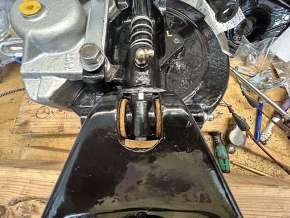
Cotter pin in place

After going through that process we discovered that the steel bushes in the used “A” arms were completely knackered with way too much play and we had to order a new pair. The “a” arms are available from British Heritage and are supposed to be as original, however, they are very expensive. A lower priced aftermarket “A” arm, produced in the UK, is also available and contributors to the on-line Sprite Forum reported that these units are satisfactory. So, we ordered a pair of these from AH Spares and repeated the process of mounting the hub assembly to the “A” arm!

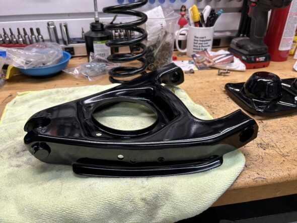
After market “A” arm and new coils spring

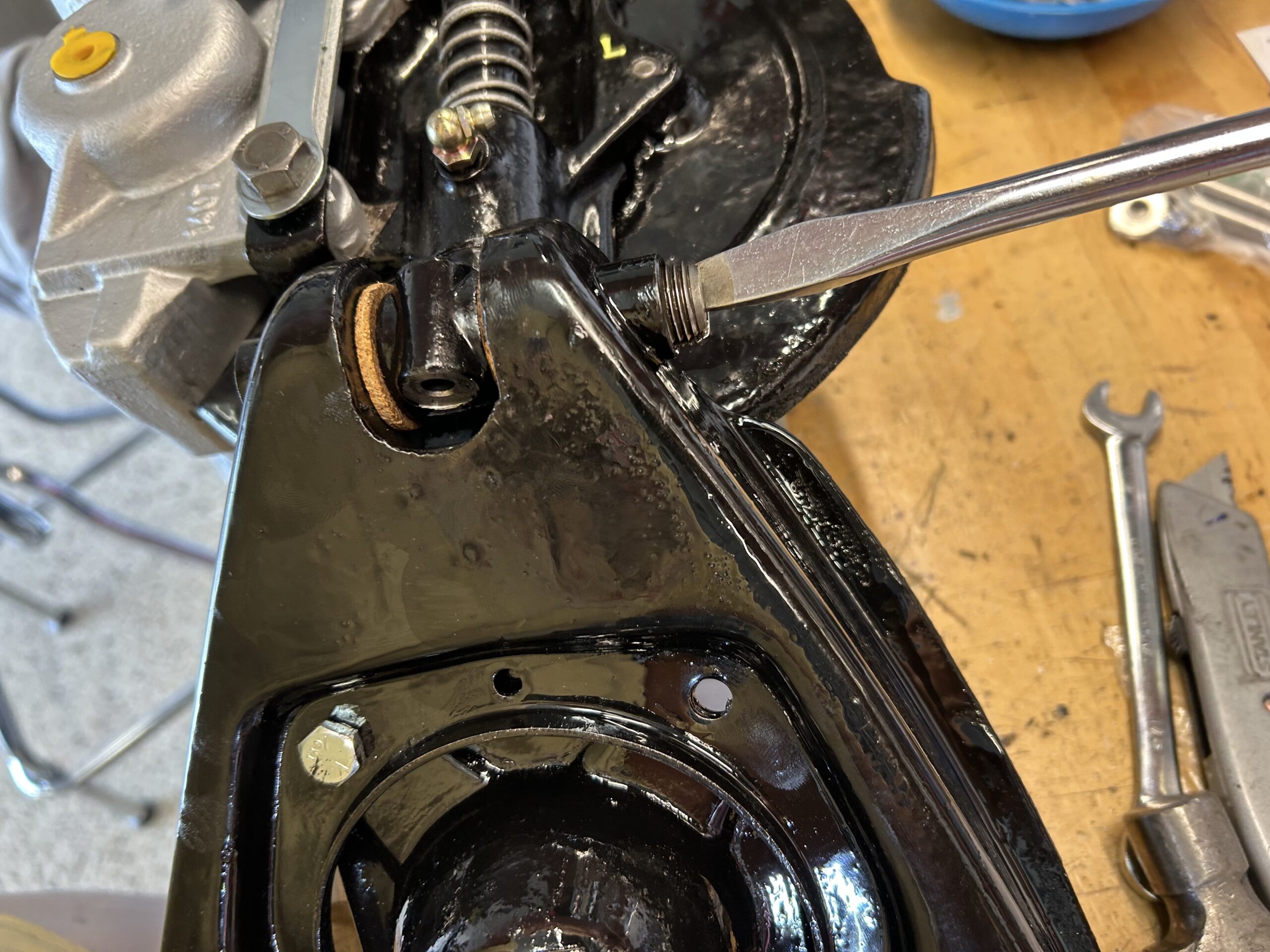
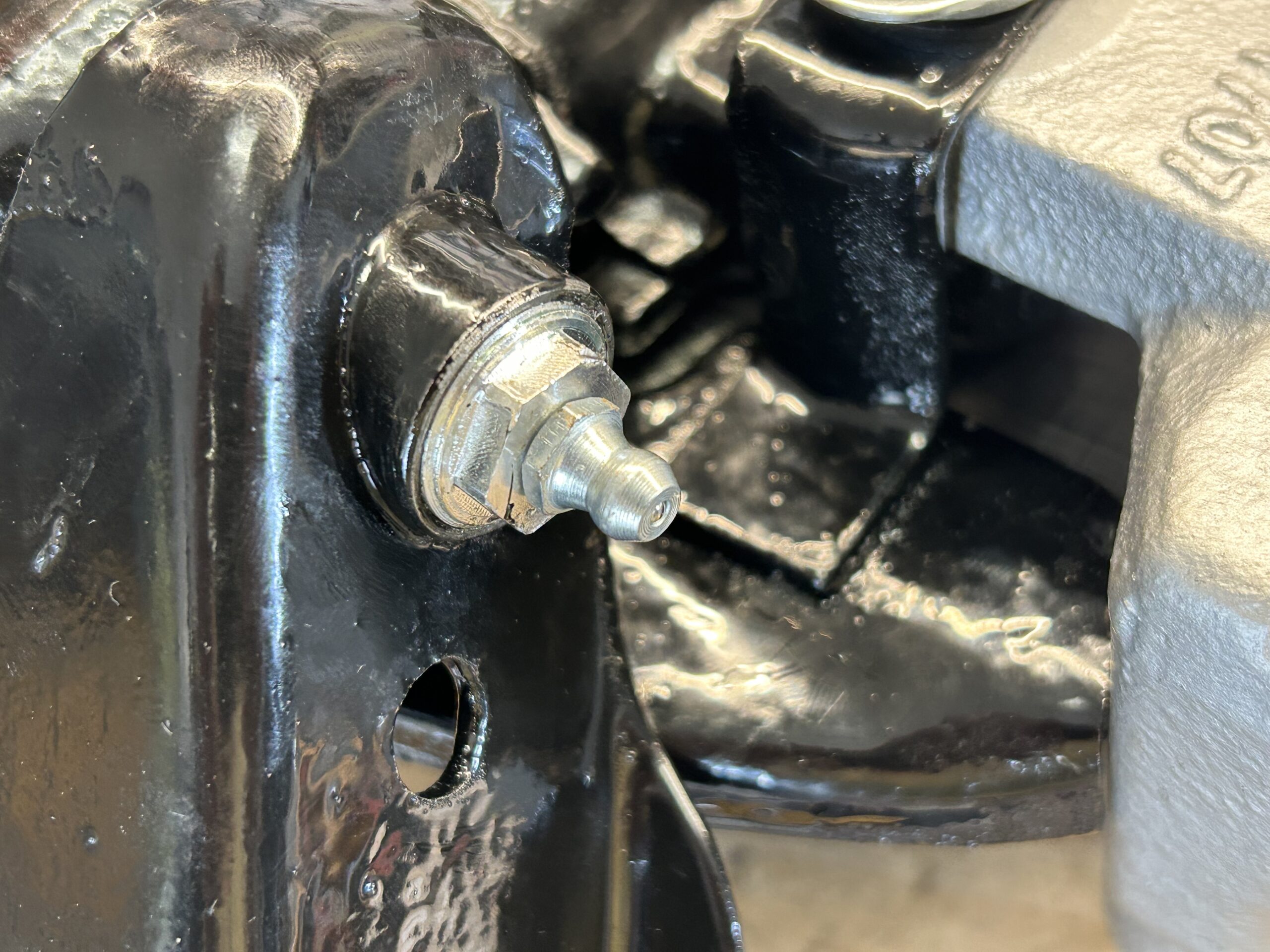
One side of the “A” arm outer bushing was already capped, but the other side required a screwed plug and grease zerk to be screwed into place.

“A” arm grease zerk fitting

The next step was to install the hub assembly and “A” arm (wishbone) to the car. While supporting  the weight of the hub assembly on a floor jack, the assembly was secured to the damper arm with the top fulcrum pin.

Supporting hub assembly to insert uppertrunbnion fulcrum pin

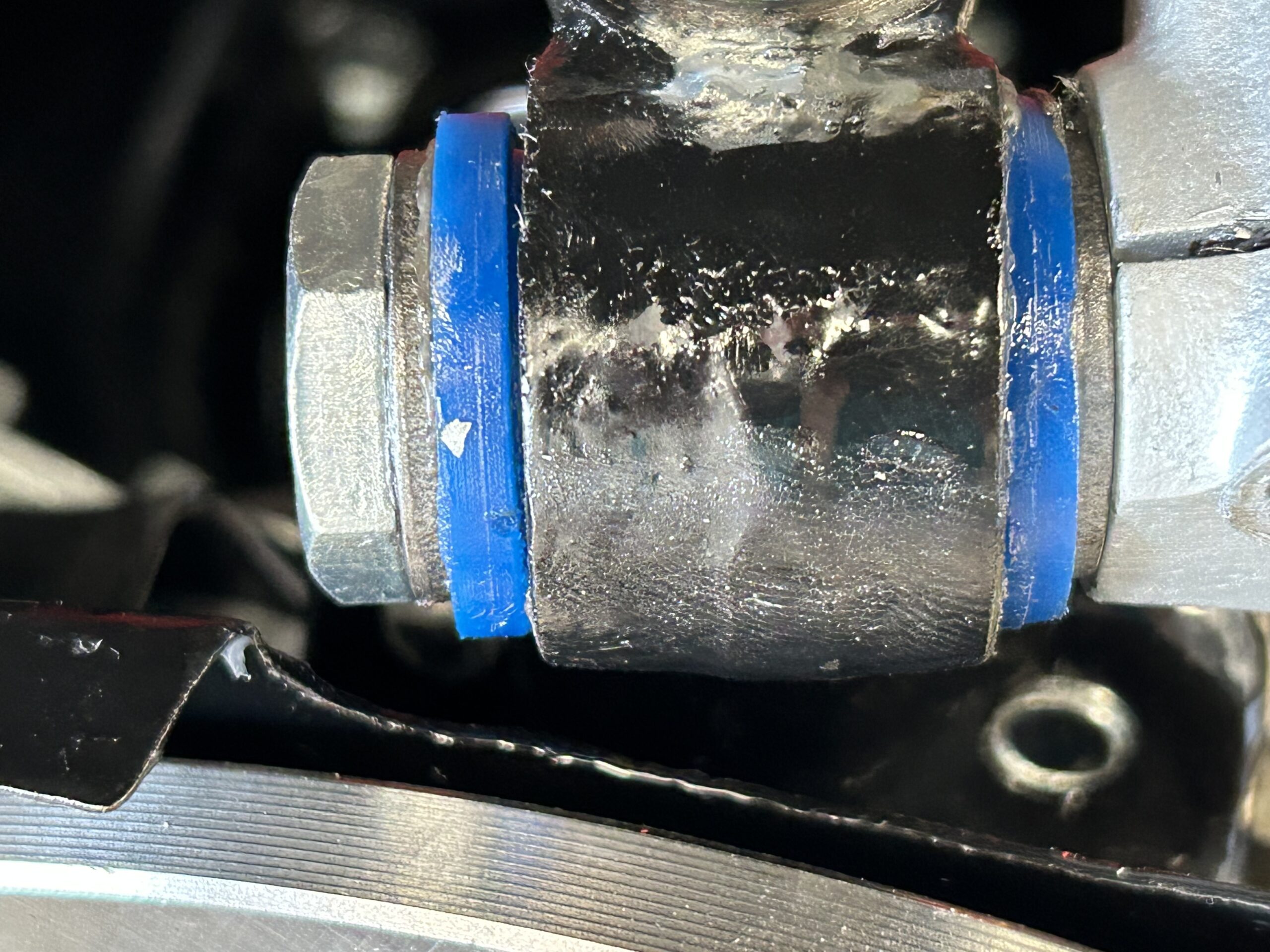
Like the lower pin, there is a concave spot on the shaft of the bolt through which the damper pinch bolt must align in order for the pinch bolt to screw into the damper arm. The top fulcrum pin is inserted from the rear through a new rear poly bush, pushed through the upper trunnion, and then through the front poly bushing before passing through the damper arm where it is then secured with a castle nut and split pin.

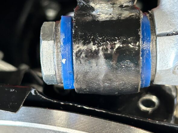
Upper Trunnion bolt washers and poly bushes

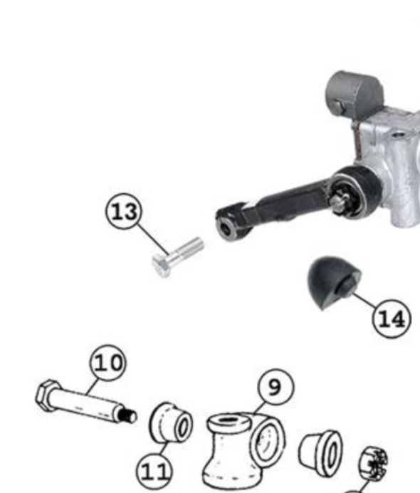
Upper Hub Assembling Mounting


The Upper Trunnion sits atop a thrust washer on the swivel axle. Two small shims are placed on the king pin below the thrust washer and upper trunnion before they are placed on the top of the king pin. After the upper trunnion is in place a nylock nut is used to tighten the swivel axle assembly. At this point we have the hub assembly secured at its top. We did not tighten the upper trunnion until after we mounted the lower “A” arm to the car.

New poly bushes were mounted on either side of the inside of the “A” arm and using a combination of a floor jack and a bottle jack the inside of the “A” arm was pushed into place so the the inner fulcrum pins could be pushed through and secured with nylock nuts. These won’t be tightened until we have the weight of the car on the ground.

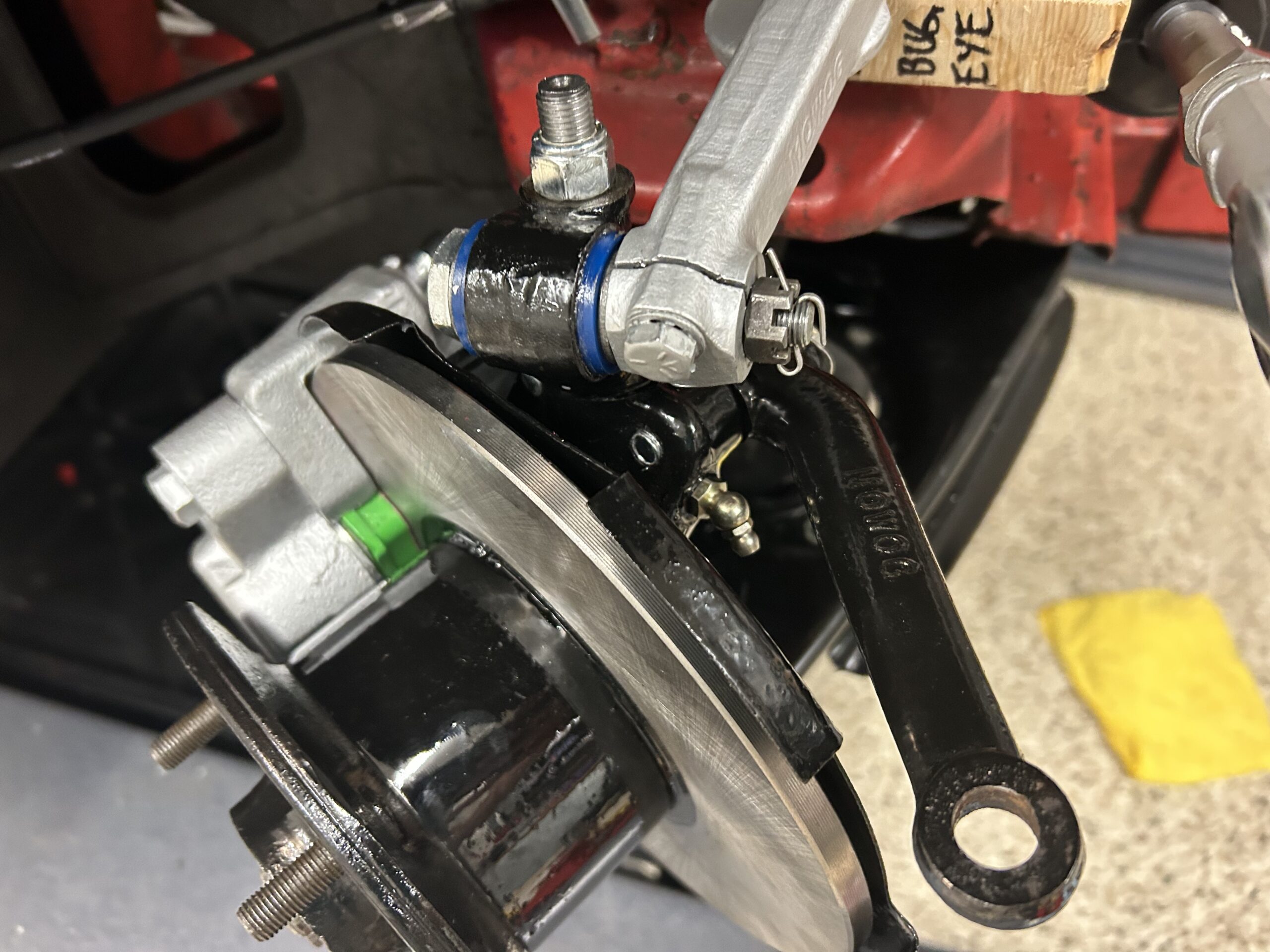
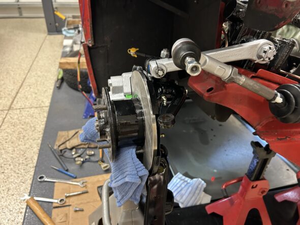
With everything mounted properly it was time to tighten nuts and bolts. The top trunnion nut was torqued to 40 ft. lbs. If the rotation of the hub (front to back) is too tight a shim is added, if there is too much play a shim is removed.

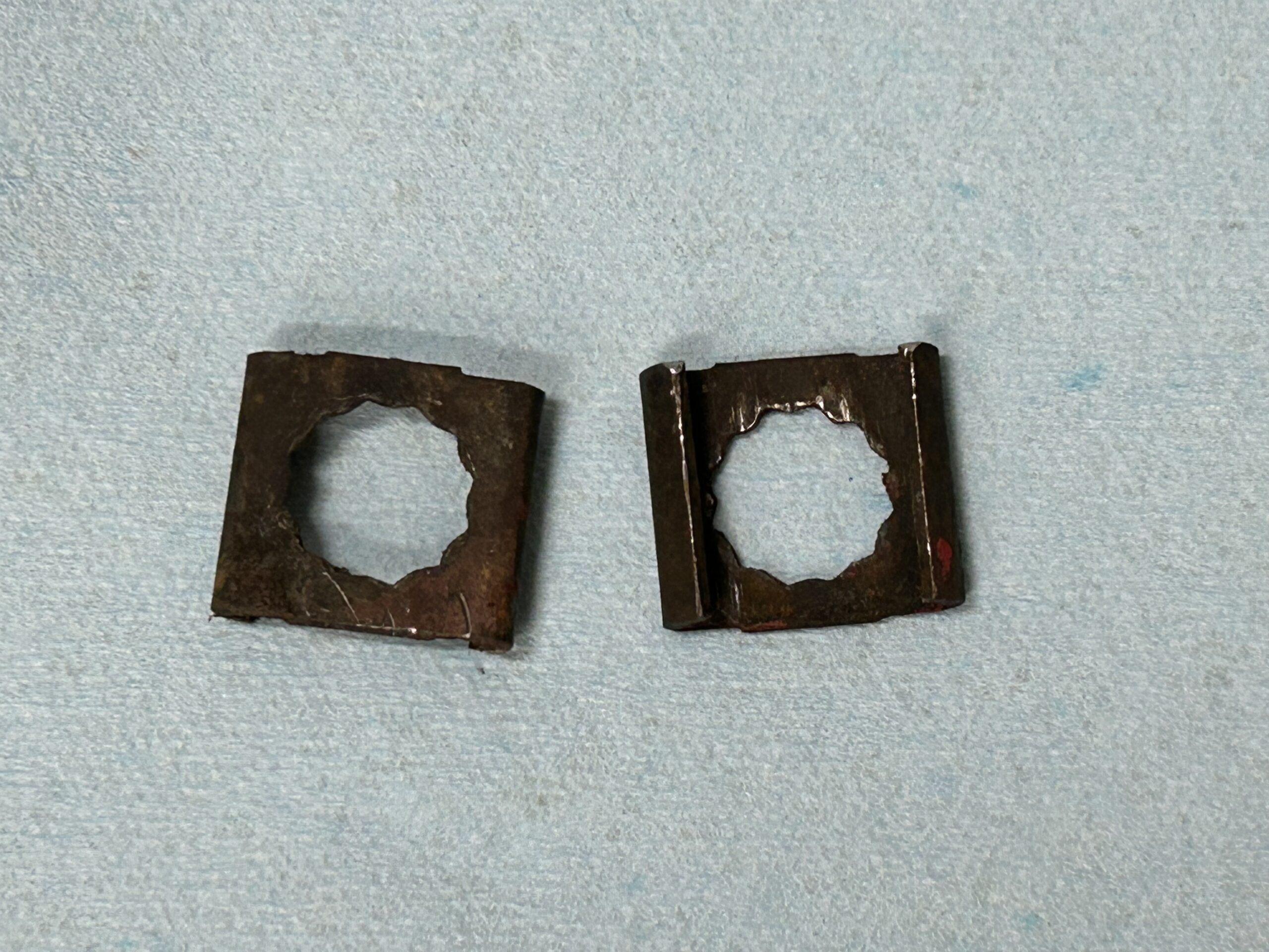
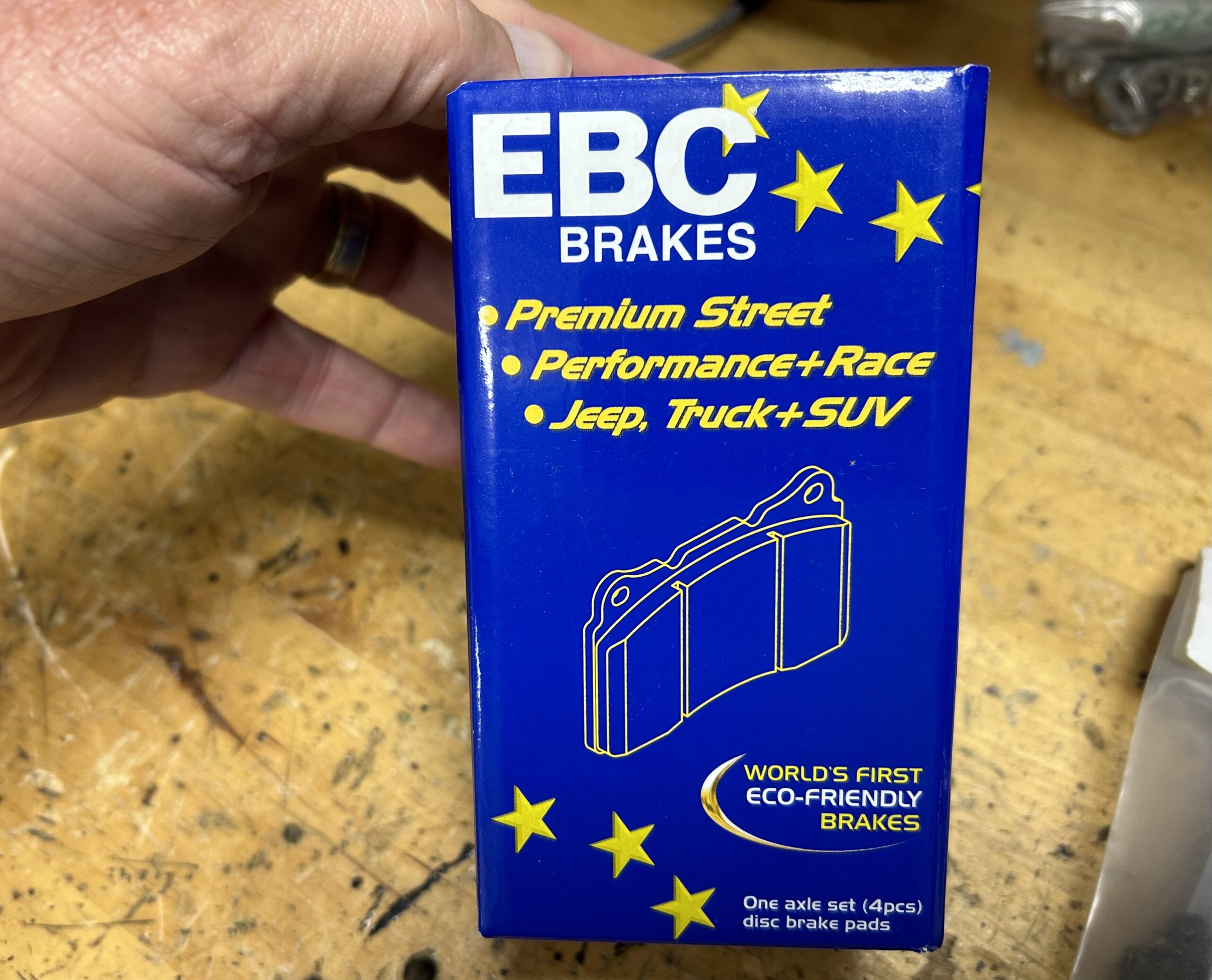
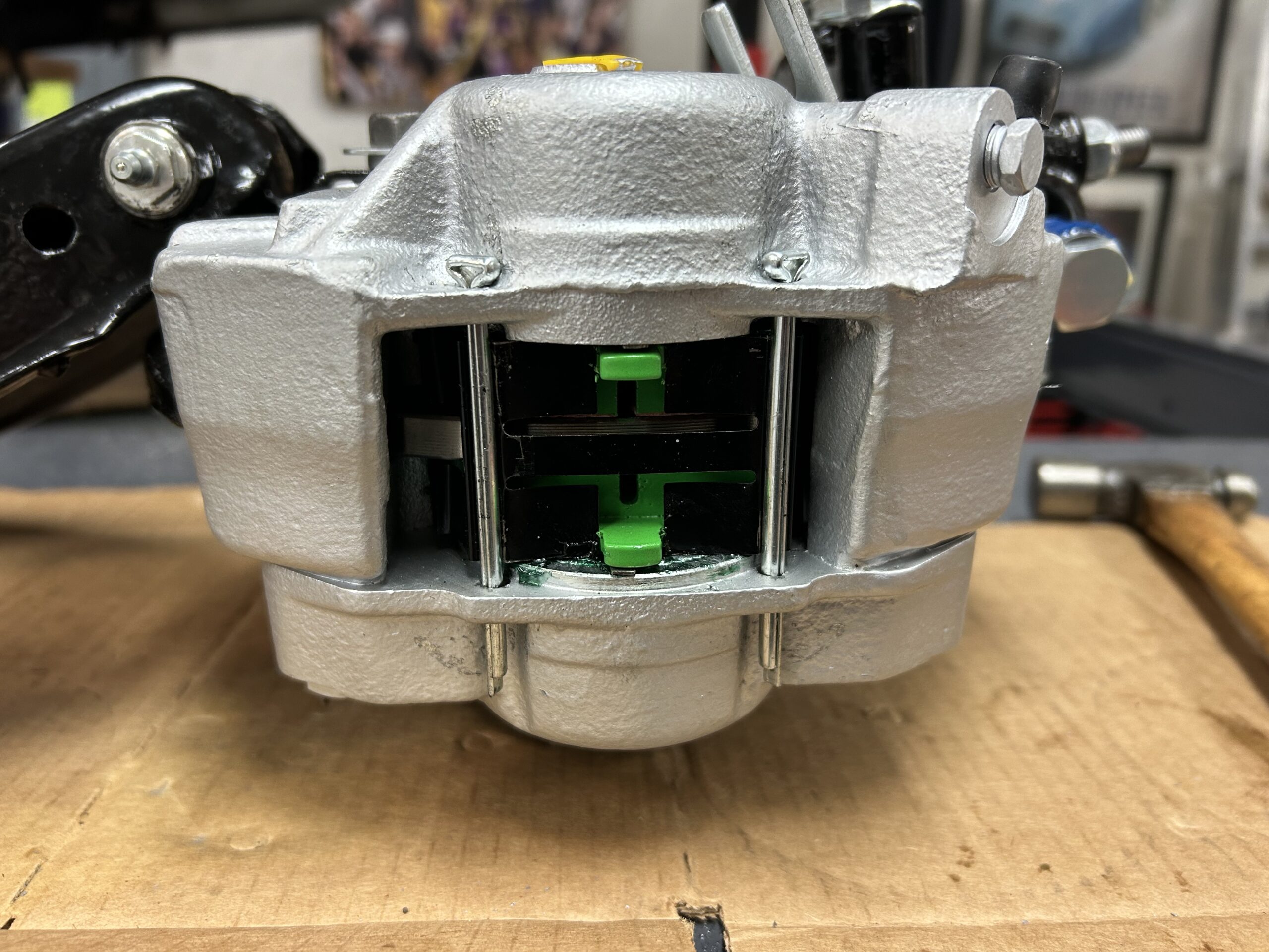
We then tightened the two bolts that secure the caliper to the swivel axle. These are tightened to 46 ft. lbs. The tab washers under the bolt heads will be turned up at a later date. The steering arm bolts were torqued to 39 ft. lbs. The tab washers under the bolt heads will be turned up at a later date. Finally, the three mounting bolts on each damper were torqued to 27 ft. lbs.

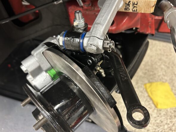
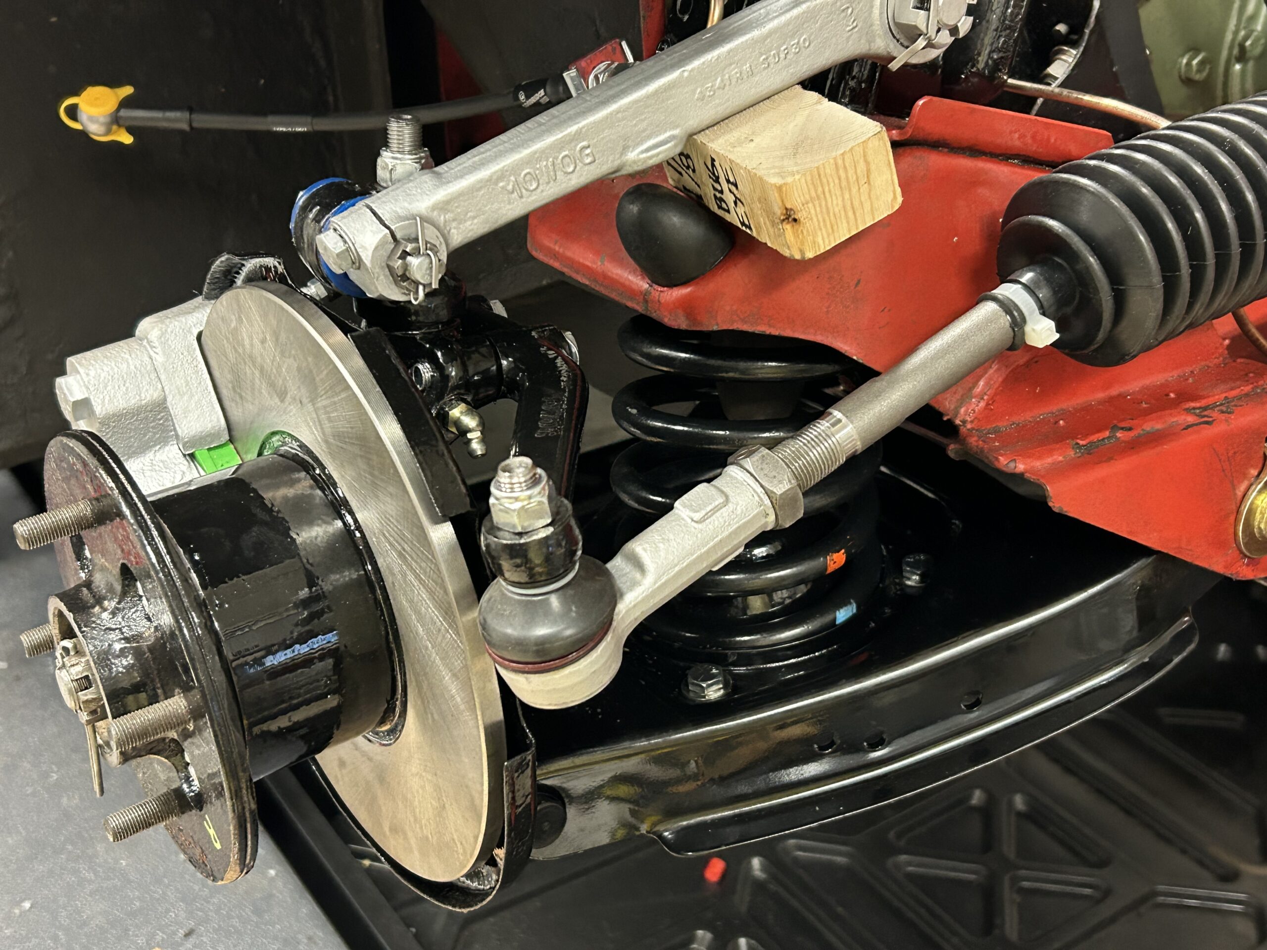
Everything buttoned up

The next step was to install the front coil springs. The spring seats, or pans, were removed  from the “A” arm. The spring was then placed on the spring seat and pushed upward through the “A” arm wishbone. Compressed springs can be very dangerous and consequently we choose to use long threaded rods to safely compress the springs.

We prepared four 5/16″ – 18 “all-thread” rods by cutting each to six inch lengths. Double nuts were placed on the top of the rods and tightened against one another. Coupling nuts were used on the top and bottom to make the nuts more accessible to turn with a wrench. Flat washers were also used between the spring seat and the nuts.

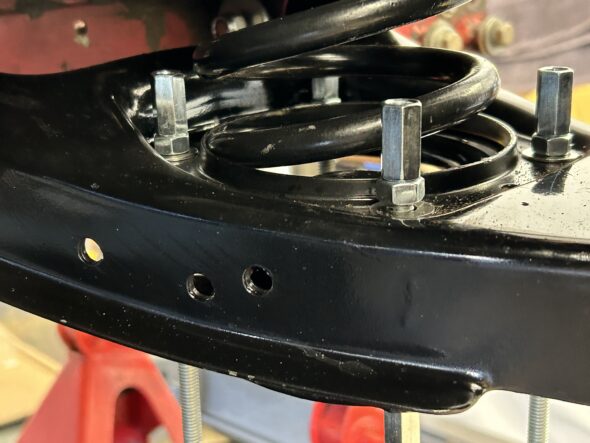
The nuts were gradually tightened until the spring was compressed and the spring seat was tight against the “A” arm. Then, one at a time, the long rods were loosened and replaced with 5/16″-24 x 3/4″ hex head bolts and nylock nuts.

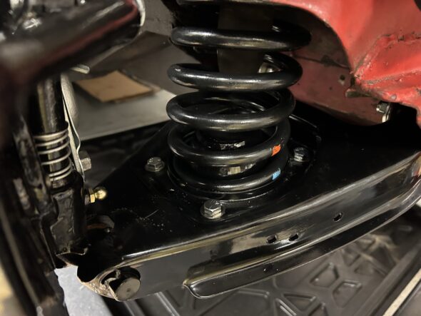
Coil spring installed

1 1/8″ wooden spacer block to simulate normal hub height

We will still need to bend back tab washers, lubricate the grease zerks and tighten the inner “A” arm fulcrum pins, tighten the hub nut and insert its split pin and install the grease caps. But, these are all little steps to be accomplished later. The big stuff is done.

Bugeye Restoration Video Episode Thirty-four addresses the joining of the hub assembly with the lower “A” arm (wishbone) and the the installation of the combined assembly to the car.

https://vimeo.com/807699575/1a3cf45eb0

The following steps are addressed in the video:

0:00 – Lower “A” arm installed to king pin and swivel axle

1:18 – Outer fulcrum pin, cotter pin and grease fitting installed

2:29 – Excessive play discovered in old “A” arms

4:00 – Lower coil spring pans installed in “A”arms

4:30 – Hub assembly and “A” arms installed in car

5:00 – Poly bushes installed in inner “A” arm and then to car

5:53 – Damper pinch bolt and upper fulcrum pin

6:52 – Torqueing the caliper, steering arms, and damper bolts

7:24 – Coil spring installation with “all-thread” rods


Front Brakes, Pedal Box and Steering Rack

Brake Pipes – Sometimes as one proceeds with working on the major systems of the car parts just get in the way! We are installing the modified Sebring-style pedal box with separate Girling master cylinders and that requires bending a new brake pipe with a different configuration from the original. To form the new pipe and trial fit it to the car we found it easier to remove the windscreen washer pump located on the firewall and to loosen the wiper motor mounting as well. “Easier” is a relative term! Not exactly easy to get to the nuts on the inside of the firewall to release the pump.

Easy is a relative term

Using the brake pipe supplied in the Bugeye brake pipe kit that has pipe cut to length with fittings installed for the pipe from the master cylinder to the pipe union proved to be a little too short so we have ordered some extra 3/16″ pipe from FedHill. The short pipe was used to go ahead and make the pipe bends that will become a model for the FedHill pipe when it arrives. 

We then went ahead and bent the pipe for the route from the union to the RH front wheel and the pipe from the union to the LH front wheel. The LH pipe runs over the front chassis crossmember and is held in place with two brake clips.

Crossmember brake pipe clips (2)

LH and RH front brake pipes at Union

To make sure that we did not end up with a conflict between the pipe and the steering rack we went ahead and temporarily installed the steering rack. Permanent installation will occur a little later.

At the front of the car the hard pipe attaches to a clip on the chassis where it is joined by a flexible black stainless steel Goodridge hose. The other end of the hose then screws into the brake caliper.

Brake hose to Brake pipe chassis clips

The brake pipe that runs from the union to the back of the car was removed, but we will wait until the engine and transmission are removed from the car to shape and install the pipe. There just isn’t enough room to maneuver to install the new pipe with the engine in the car. All of the original pipe was removed from the car and stored away just in case we need it in the future. The pipe may be ultimately tossed away but we will keep all of the end fittings.

Brake Pads – We had ordered new Gold Cup brake pads from Moss Motors only to discover that they were just slightly too thick, preventing a good fit in the new calipers. We ordered a set of EBC pads and like Cinderella, found that they were just right. These were installed with new spring retainers and split pins. We won’t bend the pins back yet.

EBC Brake Pads

New calipers, EBC brake pads, Retaining Springs and Pins

Installing the new steering rack acquired from AH Spares proved to be a simple job. The lower brackets were installed on the car with the three 5/16″ – 24 x 3/4″ bolts for each bracket. We have new shims to install in the cradle of the brackets but we aren’t going to install them now. We will wait to use the shims when the final installation on the car is accomplished after paint. After the brackets are mounted to the chassis, the rack can be lifted into place and the top brackets can be screwed into place. We left everything loose until the steering column and the steering rack were mated and the pinch bolt installed. Then everything was tightened down. The steering rack clamp bolts were torqued to 20 ft lbs. The steering rack mounting bolts were torqued to 17 ft. lbs. The steering column pinch bolt was torqued to 10 ft. lbs.

The Sebring-style pedal box was reinstalled with its proper foam gasket. The gasket doesn’t align perfectly and required some manipulation. We decided to glue the gasket/seal to the pedal box but used no adhesive between the seal and the car. Ten 1/4″ – 28 x 5/8″ stainless steel hex bolts and flat washers are used to secure the box to the car. 

Because the Sprite was manufactured to be set up as either a LH or RH drive, there is an opening in the chassis sub-structure for a pedal box on the RH side of the car. We fit a new pedal box blanking plate and gasket to this location to make sure everything fit but then removed them so they would not be damaged. The blanking plate uses only eight 1/4″ – 28 x 5/8″ bolts. We will install again after paint. While cleaning the area for the new blanking plate we discovered the original Cherry Red paint used on the car. Just a fun fact.

Original paint discovered

Blanking Plate Installed

The rebuilt front dampers were bolted in place in preparation for the installation of the front suspension. Each damper is secured with three 3/8″ – 24 bolts into captive nuts in the chassis.

Our next step will be to install the refurbished/new front suspension and brakes.

The Episode Thirty-three video includes the windscreen washer pump removal and the beginning of the brake pipe replacement with new conifer hard pipe. The rebuilt front dampers are installed along with the black Goodridge stainless steel brake hoses that connect the brake pipes to the calipers.The steering rack is temporarily installed and the EBC “green stuff” brake pads are installed in the front calipers. The steering rack is connected to the steering wheel shaft. The pedal box with its insulation seal are installed as is the new blanking plate and seal for the RH drive pedal box hole. The car’s original paint color is discovered.

https://vimeo.com/806845330/73e781c99d

The following steps are addressed in the video:

0:00 – Windscreen washer pump removal

0:20 – New brake pipe from the master cylinder to the brake pipe union

0:57 – New brake pipe from the pipe union to the front caliper

1:10 – RH front damper installed

2:18 – Goodridge stainless steel flexible brake hose installed from the hard pipe to the caliper

2:30 – LH front damper installed

2:45 – Brake pipe installed from the union to the LH front caliper

4:05 – Temporary installation of the steering rack

4:30 – Brake pipe from union to the rear axle

4:45 – Rear brake pipe connection to the flexible hose and routing under the car

6:10 – EBC front caliper brake pads installed

7:35 – Steering rack connection to the steering column

8:30 – Pedal box and seal/gasket install

10:45 – Pedal box blanking plate installation

11:00 – Original Cherry Red paint discovery