Yes, in building a new electrical system for the Bugeye we wanted to add additional circuit fusing protection, we wanted to add relays to take the load off of switches, we wanted to add “personalizations” for safety and convenience but perhaps as much as anything, we wanted to eliminate or at least minimize this:
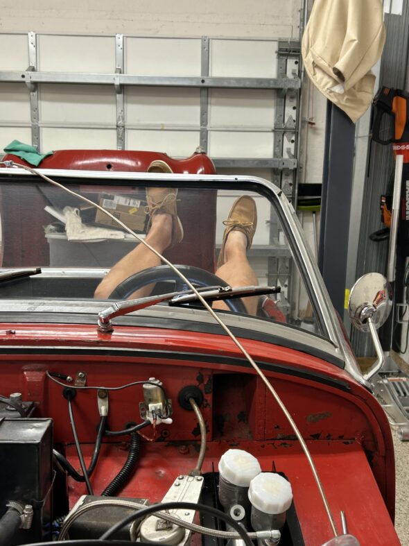
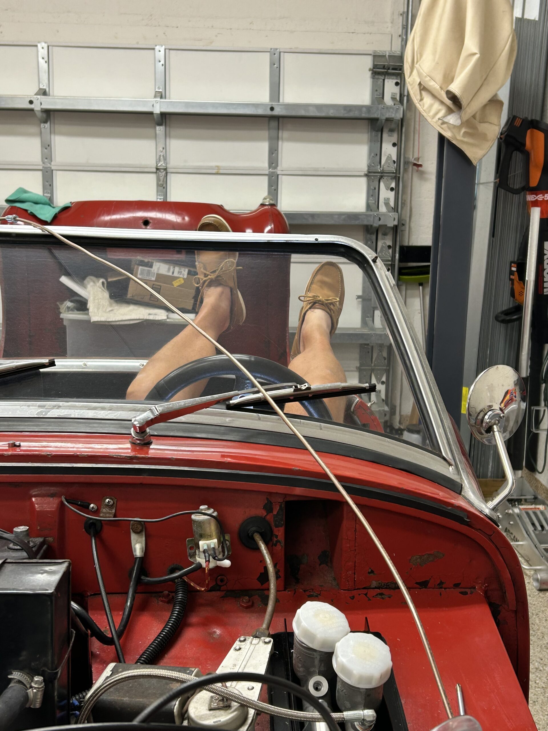
Working Under the Dash
Anyone who has done it, knows that working on the dash wiring while lying on one’s back is just no fun in the little Sprite. So, we wanted to construct a wiring harness that would take advantage of modern electrical connectors (Deutsch connectors) to make it possible to essentially “unplug” the dash with all of its gauges and wiring in tact and remove it from the car. The water temperature/oil pressure gauge, choke cable and the heater switch complicate this proposition a little, but disconnecting them for removal are minor compared to lying on your back on the floor of the car!
The previous post, “A New Electrical System,” detailed all of the electrical system modifications we are making in the Bugeye. This post covers creating, testing and removing the central wiring harness that serves the engine bay and the dash. Three videos were created to show the process.
Later, we will build the wiring harnesses for the bonnet and for the rear of the car.
The following Bugeye Restoration video episode fifty-three covers the initial work done on the wiring:
https://vimeo.com/913981383/62234c4caa?share=copy
0:00 – Fuse box, power supply to fuse box
2:30 – Deutsch connectors, wiring routing
5:25 – Hella horn wiring
7:00 – Deutsch connector from body harness to bonnet harness
8:00 – Removing the harness from the car
9:00 – Disconnecting the wiper controller
10:00 – Harness removed from the car
10:25 – Taped harness
Bugeye Restoration video episode fifty-four covers the fabrication of a switch and control panel hidden behind the dash. The panel includes toggle switches for the radiator electric fan, the courtesy interior lights, the driving lights and the fuel pump selection. The hazard flasher switch, the rheostat for the wiper speed controller and a combination voltmeter and USB port are also mounted on the panel. The video then focuses on the wiring for the gauges and switches on the dash.
https://vimeo.com/913992798/07c6df6f44?ts=0&share=copy
0:00 – Supplemental control panel behind the dash
2:05 – dash wiring
3:12 – Fuel gauge
4:00 – Magnetic wiring clips
4:25 – Speedhut Speedometer and Tachometer
7:15 – Ignition and light switch
8:40 – Panel lamp switch
9:00 – Turn indicator switch
9:15 – Hazard flasher diodes
Bugeye Restoration video episode fifty-five covers the testing of the wiring circuits before the central harness is removed and taped.
https://vimeo.com/914010274/237d25f4f3?share=copy
0:00 – Testing the wiring harness and the connectors
3:00 – Wiper controller
3:10 – Toggle switches on the control panel