About valv8988

Welcome to my website covering the history, restoration and “personalizations” to my small collection of classic cars. Feel free to email me with questions, suggestions and/or comments. I would love to have your feedback! Cheers, Lin Rose [email protected]

Engine Starting

Fire in the Hole! Well sort of. We have been working on getting this engine running for some time. The focus in this video is the ignition. We suspected that the distributor was installed 180 degrees out, so we pulled the distributor and its drive. We flipped the drive gear over so that the larger “half” was on the top and reinserted it into the housing. Reinstalled the distributor and connected the spark plug wires and fired it. The engine ran but was very rough with considerable knocking and banging around. Looks like the ignition issues may be corrected, so now it is time to turn our attention to the carburetors and the fuel side of things.

The 5/16″-24 x 3 1/2″ Bolt used to withdraw the distributor drive needs to be threaded into the drive dog BEFORE the black housing is removed! Also, attention needs to be paid to the proper replacement of the distributor mounting plate – the bolt head must face the front of the car – NOT the nut!

This video Episode Twenty-five provides a summary of the process of correcting the orientation of the distributor drive dog and the firing of the engine: https://vimeo.com/774454868/69e2fc7381

Carburetor Tuning – Video Episode Twenty-six covers the tuning of the HS2 SU carburetors on the Bugeye. We discovered that turning the jets down an equal number of turns on each carb did not produce equivalent results, so we instead measured the the depth of the jet from the bridge in each carb body. While we will surely do some more fine tuning, we ended the video with each of the jets down 2.5mm. The throttle adjusting screws were set to synchronize the two carbs using an air flow meter. The end result was pretty smooth idling and running with the idle at about 750 rpms. The exhaust is still a little uneven. We will put a timing gun on it before we are completely finished it to complete the tuning process. https://vimeo.com/774463593/b2605101e8

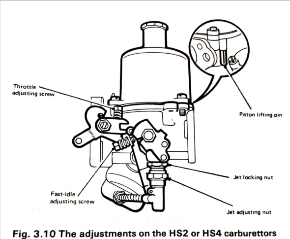
HS2 Carb Adjustment

We found these instructions for HS2 tuning in the Haynes Repair Manual for the MG Midget/AH Sprite 1958-1980 to be very helpful:SU carb tuning-page-2

Interior Removal

This will be a gradual process, but we did begin the removal of the interior components. Most of the interior will be replaced with new parts, but we will save everything until the new pieces are installed near the end of this project.

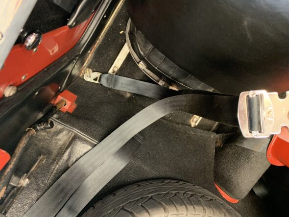
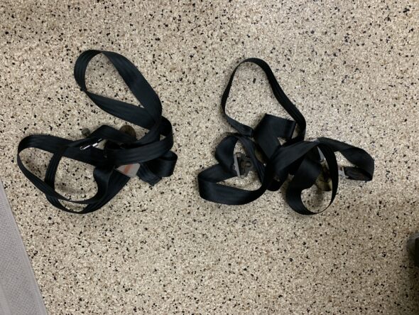
The first action taken was to remove the shoulder harness mounting points for both seats. We will probably replace these with retractable belts when we are at that point in the rebuild.

Shoulder Harness Removal

Shoulder Harnesses

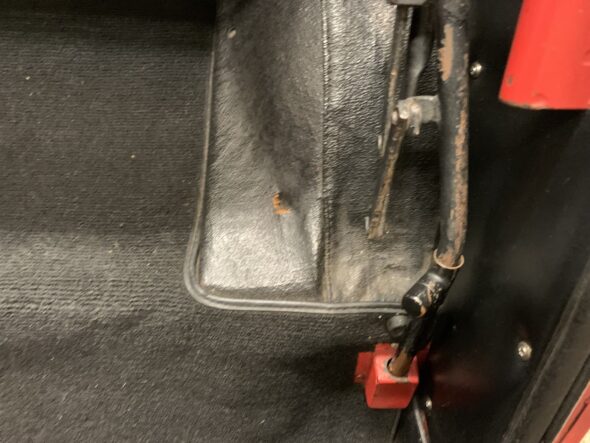
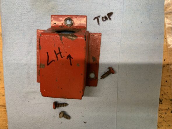
At :13 in the video Episode Twenty-Two summary the soft top frame stowage bracket is removed. Each bracket is held in place with three self-tapping sheet metal screws.

Soft Top Frame Stowage Bracket in Place

Soft Top Frame Stowage Bracket

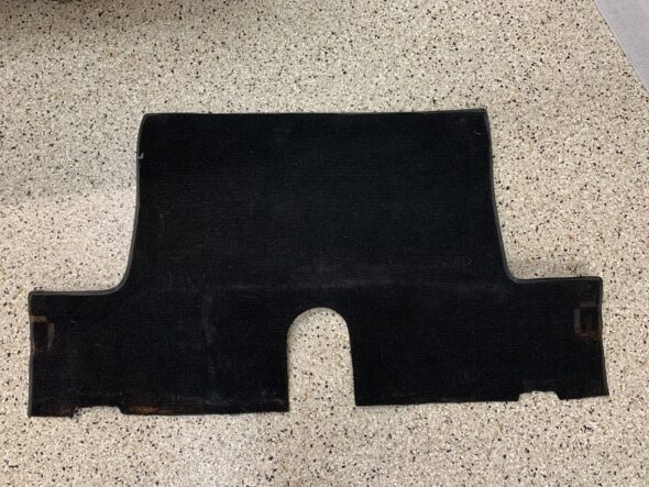
Next was the removal of the rear shelf carpet and its securing snaps. The process begins at the 1:00 minute mark in the video.

Rear Shelf Carpet

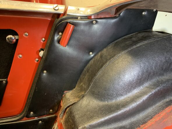
At 1:25 minutes into the video, the rear upholstered quarter panels and hardura covered wheel wells are removed.

Quarter Panel and Wheel Cover removal

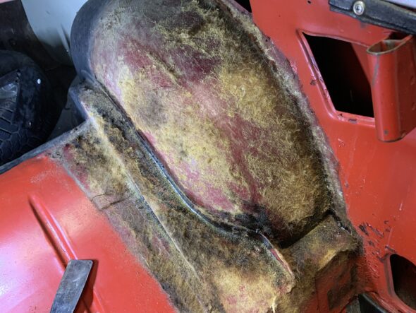
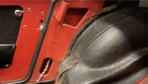
Because the hardura wheel covers are glued in place, they left quite a mess when removed. We will need to try some adhesive removal to clean the surfaces.

Hardura Residue at Wheel Wells

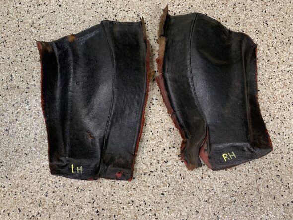
We discovered that the covers were originally red. A previous owner had dyed or painted them black.

Hardura Covers removed

Although not removed at this point, it was noted that the wiring harness to the rear of the car is routed through a hole in the frame that is covered by the rear quarter panel.

Wiring Harness Behind rear Quarter Panel


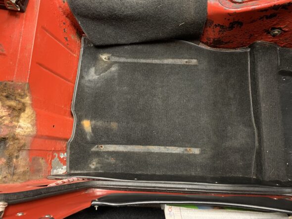
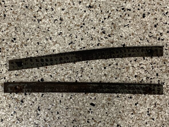
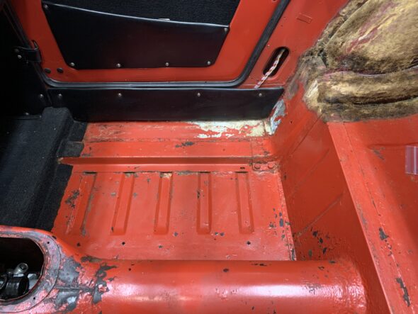
At 4:24 into the video, the RH side seat, seat rails and carpet are removed. Each seat rail is secured to the floor with two bolts into captive nuts.

RH seat, seat rail and carpet removal

There is a wooden packer piece between the carpet and the floor for each seat rail.

Wood Packing Pieces at the Seat Rails

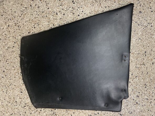
The upholstered panel under the RH door was then removed. It was held in place with four self tapping oval head screws with cupped trim washers.

Upholstered Panel Under the RH Door

Episode Twenty-Two summarizes the removal of the interior components highlighted above. https://vimeo.com/770800213/f36ec43100

RH Side Front Kick Panel  and Carpet – On November 17, while working on the final installation of the fuel delivery system it became necessary to remove the RH side front kick panel and front carpet. The kick panel was held in place by three self-tapping oval head chrome screws with cup washers and the two slotted screws that hold the door check strap in place. Once the fasteners were removed the kick panel was lifted out of the car exposing the wiring harness that is routed to the rear of the car.

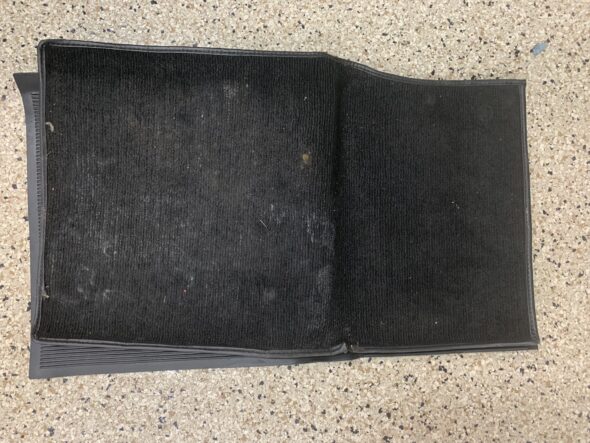
The carpet was held in place with two floor snaps at the top of the carpet.

Video Episode Twenty-four summarizes the removal of these components:https://vimeo.com/773034332/b4bf5c4504

RH front kick panel

RH Side Front Carpet


Propshaft, Axle and Fuel Tank Install

Axle Install – This process has taken longer than expected but it is now time to reinstall the prop shaft, the rear axle, the new fuel tank and to connect the fuel delivery lines. Installing the prop shaft can be a bit of a struggle because of the flexible front yoke, but it was much easier with the axle and fuel tank out of the way. A clear look at the target (rear of the gearbox) is possible with the axle out of the way. The Episode Twenty video shows the quick job of the prop shaft install: https://vimeo.com/770233750/3412849430

Details of the installation process of these components is provided below. However, the Episode Twenty-One video also summarizes the installation: https://vimeo.com/770295832/305b6fdd14

Before reinstalling the axle into the car, we needed to install the axle brake pipe securing straps to the axle housing. These were not on the car when we acquired it, but the brass straps, which are very similar to the original straps, can be purchased from Moss motors. These are easy to install. One first loops the strap around the brake pipe and then around the axle housing. There is one for each side of the axle.
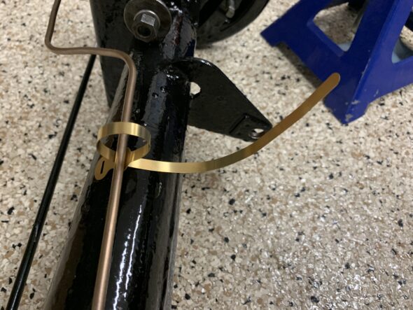
Brake Pipe Axle Straps
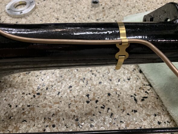
Axle Straps Installed

Garage assistant Fiona, using the floor jack, lifted the rear axle and pushed it forward under the car.
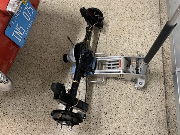
Axle on Floor Jack

After a little manipulation we were able to put the special bolts for the spring eyes and for the radius arms into position and secure with nylock nuts. Works best to install the radius arm bolts first, then leaf spring eye bolts. Nothing was tightened completely and won’t be until the car is on the ground.
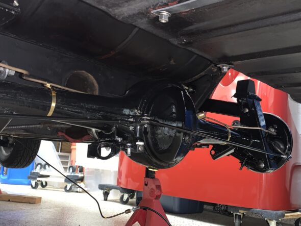
Axle in Place
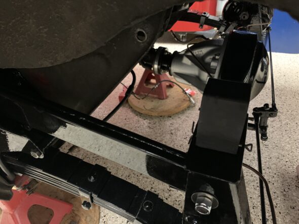
Connecting Axle to Suspension

We were then able to install the prop shaft spacer onto the end of the unit and attached it to the rear differential with grade 8 5/16” x 24 x 1 1/2” bolts with nylock nuts.
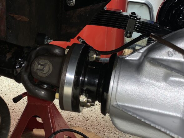
Prop shaft spacer

Just so we wouldn’t forget we went ahead and tightened the axle assembly nuts to 140 foot pounds of torque. We then bent the tab washer down over one facet of the nut.
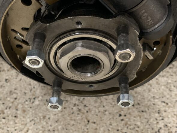
Axle Nut Torqued to 140 ft. lbs.
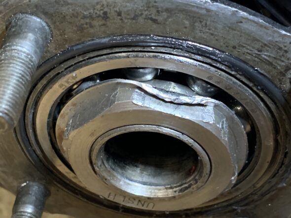
Locking Tab Washer Folded Over the Nut

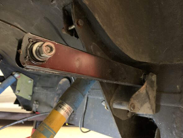
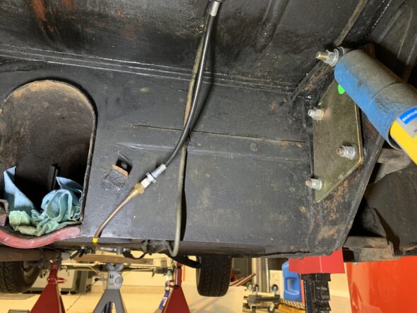
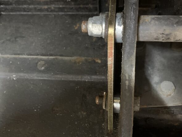
Bilstein Shock Install – Our next step is to install the rear Bilstein tube shocks. The lower mounting bolts are ⅜”-24 with 9/16” hex heads. Note the spacer on the lower mount must be in the hole properly before tightening down the assembly. With the original leaf springs we had the lower mount bolt head closest to the springs and the nut closest to the differential,  however, with these new springs the shackle for the springs conflicts with the bolt and makes it almost impossible to insert it into the mounting point. So we just switched the direction.
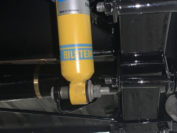
Lower Shock Mount
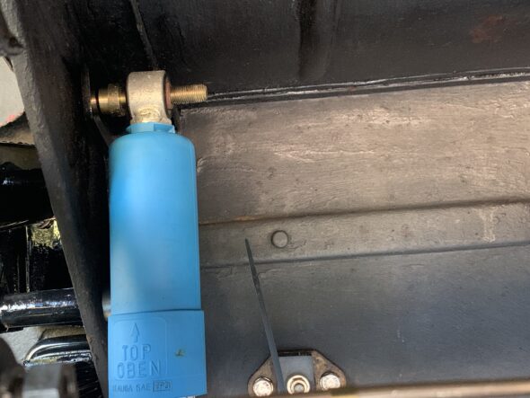
Upper Shock Mount

Rebound Straps – Next, is the installation of the rear axle rebound straps. New straps from Moss Motors are used. The top bolt is a ⅜”-24 x 1 ¼”. The lower mount is a ⅜”-24 stud affixed to the axle casing.
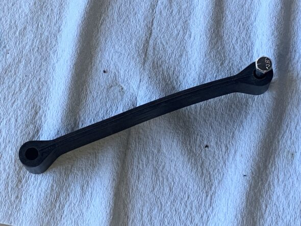
New Rebound Straps
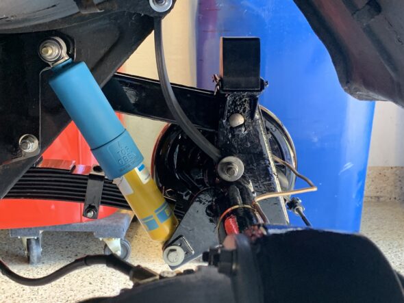
New Rebound Straps Installed

Hub Seals – After bending down the locking washer tab on the axle nut, a new rubber “O” ring was pressed into its hub cavity.
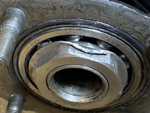
Rubber “O” ring Installed in Hub

Followed by the paper gasket which was coated with Permatex high tack gasket sealant on both sides before installing the axle half shaft. This sealant was recommended by Mini Mania and was used in their YouTube video of the Sprite rear axle assembly.
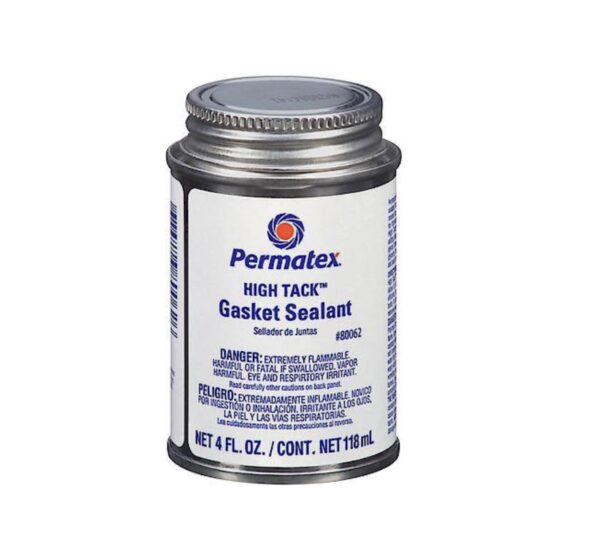
Permatex Sealant
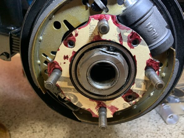
Paper gasket installed with Permatex High Tach on both sides

We then installed the axle half shaft and quickly screwed in one of the countersunk pozi drive screws into the axle hub.
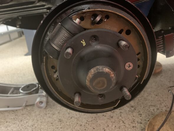
Axle Half-shaft Installed

Brake Drum – We then installed the brake drum and screwed in two of the pozi drive screws through the brake drum into the axle half shaft and the hub. Those screws were tightened as tight as possible and then we installed four hub nuts on the hub studs and tightened those. I could then re-tighten the two screws. That should give us a good seal.
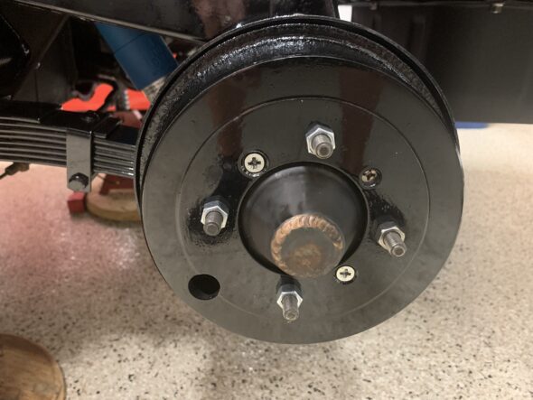
Brake Hubs Installed

That completed the axle work for the time being so we reinstalled the fuel tank being careful to connect the power wire to the fuel tank sender. This was a quick and easy job.

Fuel Pipe – We then installed the fuel pick up line from the front of the tank over the axle and to the new location for the SU fuel pump.
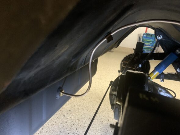
Fuel Pipe from Tank to Pump
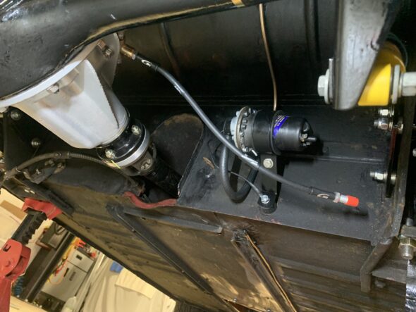
Fuel Pipe to Pump

Reconnect handbrake cable at rear axle, fill rear Differential with oil and install fuel tank filler pipe – We reconnected the handbrake cable in the same position that it was prior to disassembly. 15/16″ of threads showing. We will ultimately replace the handbrake cable with a new one, so this is just temporary and of course we will need to adjust the shoes in the brakes and then adjust the handbrake tension.
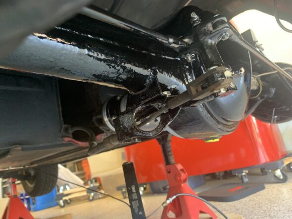
Handbrake Cable Connection to Lever
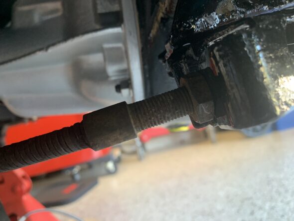
Thread Runout on Handbrake Cable

We then filled the rear differential with just under 1 quart of MT 90 gear oil. The Red Line MT 90 product is a 75W – 90 synthetic G4 gear oil. We used a syringe to push the oil into the filler plug hole until it just starts to drip out of the hole then installed the filler plug
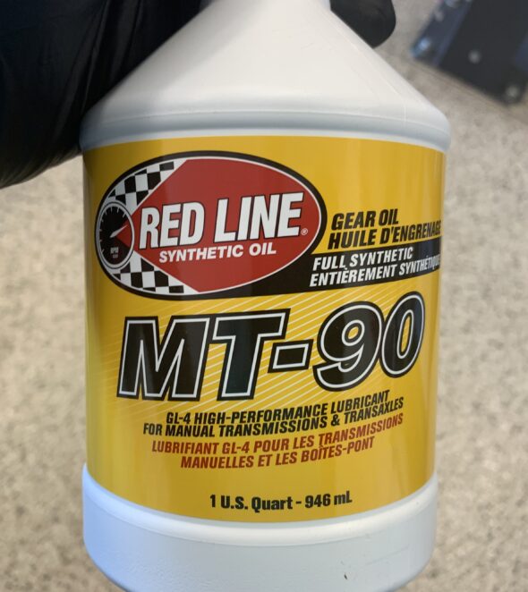
Red Line MT-90

Fuel Tank Filler Pipe Install – As stated previously, the original fuel tank for the Bugeye had the filler pipe welded to the tank as one piece. The Bugeyeguy supplied fuel tank has a separate filler pipe which is joined to the tank with a rubber collar and two hose clamps.
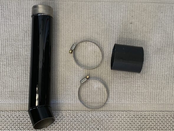
Fuel Filler Pipe, Rubber Sleeve and Clamps
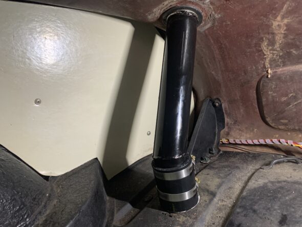
Fuel Filler Pipe Installed

We were finally able to get the car off the jack stands and onto the ground. Now it is time to move to the front suspension.
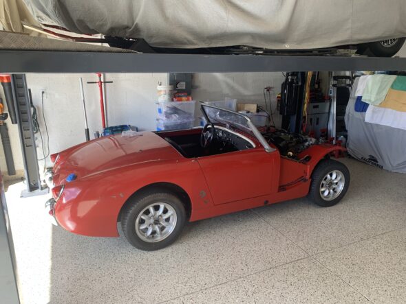
Finally, Back on its Tires

Finishing Up the fuel delivery and Suspension – We got the Bugeye up on the lift on November 17 to make it easy to tighten all of the fasteners associated with the rear suspension. We also added a fuel filter in the hose from the fuel tank to the fuel pump.
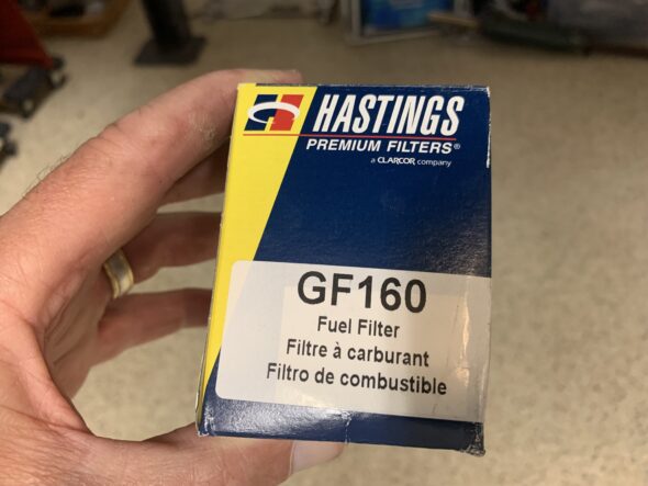
Hastings Fuel Filter GF160
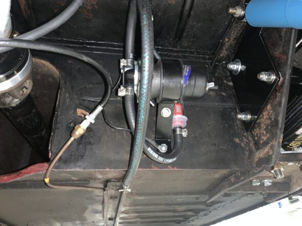
Fuel Filter, Pump and hoses

Video Episode Twenty-three shows the work done in finishing the suspension and fuel delivery systems: https://vimeo.com/773027554/131aff730b

Temporary power to the fuel pump – We will address a permanent solution to routing an electrical wire to the fuel pump when we work on a new wiring harness. As a temporary solution to test the fuel delivery system to the carburetors, we simply ran a wire from the switched side of the fuse panel, through the firewall, along the RH seat rail and through the seat belt bolt hole in the interior floor to the fuel pump. To accomplish this we went ahead and removed the RH side front interior kick panel and front carpet.



Bugeye Fuel Pump, Fuel Tank & Fuel Pipes

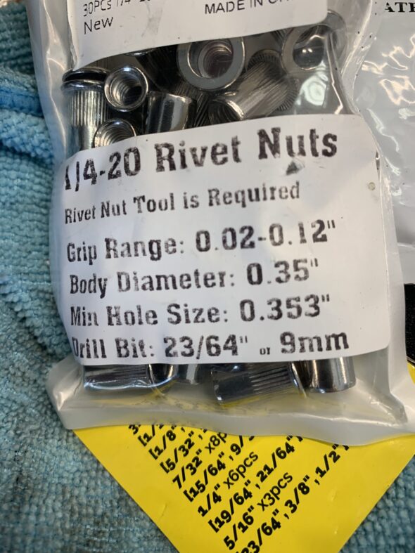
Fuel Pump – We converted from the manual fuel pump on the 948 engine to an SU electronic pump a long time ago. For years the SU pump has been mounted under the bonnet, but it is time to move the pump to the rear bulkhead near the fuel tank and axle. This is a fairly simple job. After figuring out the ideal location, holes were marked for drilling and two 1/4″-20 steel nut serts were installed in the bulkhead.

Riv Nuts or Nut Serts

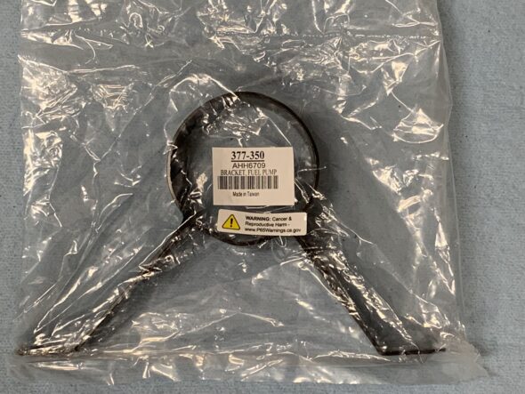
A mount for a later MG Midget and a rubber cushion were ordered from Moss Motors for the installation.

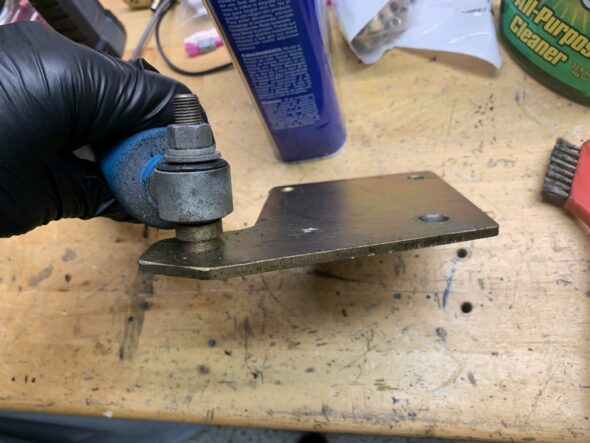
Fuel Pump Bracket

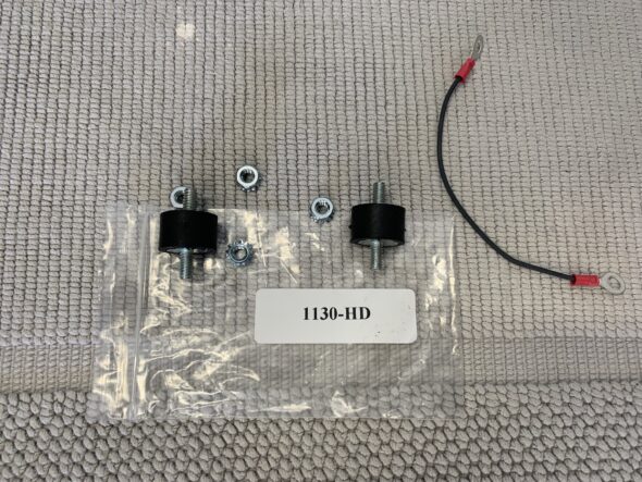
Although not shown in the initial videos, two rubber mounts were ordered from Pegasus Racing and installed to dampen the pump vibration.

Fuel Pump Isolators

Video Episode Seventeen summarizes the work performed in relocating the fuel pump. https://vimeo.com/770047578/9e09186ee0

Fuel Tank – The next step will be to paint and trial fit the new fuel tank. The new tank was sourced from BugeyeGuy. It came with a new sender and viton seal installed, and the tank was pressure tested for leaks. The kit also included a foam seal to fit over the filler pipe between the tank and the body, as well as some rubber strips that fit between the tank and the body at each stud fixing point. All six of the studs were in pretty rough shape so they were all cleaned and a thread chaser was used on each one.

Unlike the original tank that has the filler pipe and tank as one piece, the new tank has a separate filler pipe with a rubber hose collar and two hose clamps to join the filler pipe to the tank. This is done from inside the car after the tank is installed.

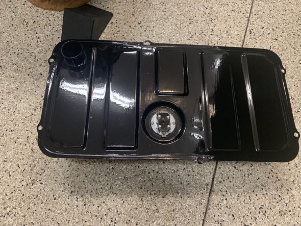
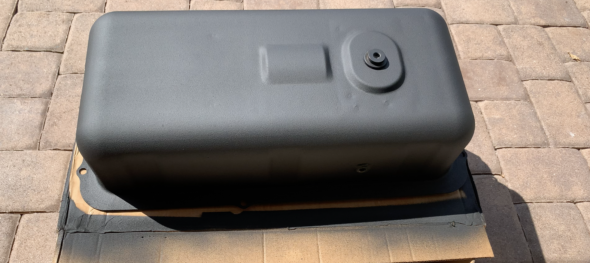
The tank had a pretty good paint job as it arrived from BugeyeGuy, but we chose to repaint the top of the tank with POR-15 to add some rust protection. The underside of the tank was painted with 3M Rubberized Undercoating.

POR-15 on Top Of fuel Tank

3M Undercoating on Bottom of Fuel Tank

We will then remove the tank to make it easier to install the rear axle. Once we have the prop shaft and axle in place, the new fuel tank will be reinstalled. The Episode Eighteen video shows the removal of the old tank and the power wire to the fuel gauge sender, as well as a general clean up of the underside of the car in preparation for the axle and tank.

https://vimeo.com/770216486/10dd8a7cb9

Fuel Delivery – The fuel delivery from the tank to the carbs uses a combination of hard pipe and 1/4″ ethanol resistant rubber fuel hose. A short piece of pipe travels from the fitting on the fuel tank, over the axle and is secured by a few clips on the body, to a piece of rubber hose that connects to the input port on the fuel pump.

Video Episode Nineteen shows the fuel pipe/hose routing from the fuel tank:

https://vimeo.com/770224843/9889f07d88

Before final assembly a fuel filter will be added prior to the fuel pump input port. Another short piece of rubber fuel hose connects the output of the fuel pump to the hard pipe that is clipped to the underside of the car and then travels up to the front of the car and across to the LH side near the carbs.

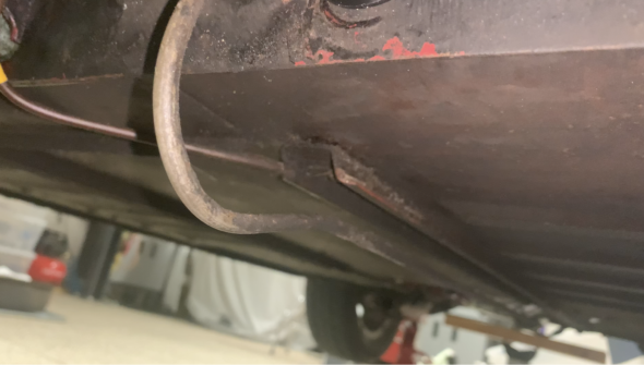
Fuel Pipe Under Car

The pipe is held to the channel by two clips that look like those on the right in the image below:

Pipe Clips

Another short piece of rubber hose connects the hard pipe to the front carb. The hard pipe we are running to the front of the car is temporary to permit testing the fuel delivery system. Upon final assembly the hard fuel pipe will routed somewhat differently.

Bugeye Rear Suspension Removal and Reinstallation

The rear suspension in the Bugeye is comprised of the quarter elliptical leaf springs, the shock absorbers, the radius arms and their mounting boxes, the rebound straps, the rubber bump stops, and of course, the axle. Video Episode Thirteen shows the removal of the original fifteen leaf springs: https://vimeo.com/769992972/c923375ecc

We chose to replace the original springs. The only springs readily available at this time are the 10 leaf “Rally” springs. We ordered a pair from BugeyeGuy.com along with five degree shims that will lower the car to give it a proper ride height. We disassembled these springs, removed the poor paint, cleaned them and repainted with POR-15 and installed teflon tape between each leaf to reduce friction and squeaking. That process is shown in Video Episode Fourteenhttps://vimeo.com/754389824/9ab8550b67

We wanted to clean and paint the radius arm bracket, the shock brackets and the radius arms so these components were removed from the car. This is seen in Video Episode Fifteenhttps://vimeo.com/770007831/bc38a03b36

Radius Arm

Rear Shock and Mounting Bracket

Shock Bracket Spacers

Spacer Between Shock and Bracket

After getting everything cleaned and painted it was time for re-installation. The following Video Episode Sixteen shows that process. https://vimeo.com/770028004/a16a02bd5d


Bugeye Rear Axle Assembly

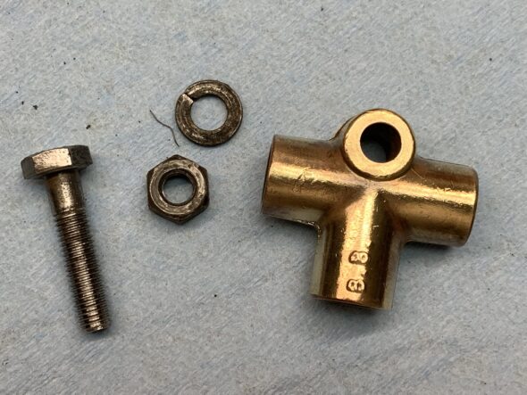
Since the last entry, the axle was painted with POR-15. The preassembled MG Midget brake assemblies were mounted to the axle and rotated to be in the proper position to align with the handbrake rods. Initially they were installed in the wrong orientation. The 3.9 differential was installed in the axle as well as the new cunifer brake pipes. The brake pipe union was cleaned and polished. A new Goodridge black stainless brake hose was connected to the union using a new copper crush washer.

A new brass Land Rover axle breather was purchased and installed on the axle. The MiniMania adjustable handbrake rods were painted and connected to the brake levers and the compensator lever with new clevis pins and felt anti-rattle washers. Finally, the rubber rebound buffers were attached to the axle with the ends of the split pins facing to the front of the car and rubber caps were placed on the bleeders. All of this work is shown in video Episode Nine.

https://vimeo.com/769593182/8c2f05ffc9

Installing the hubs turned out to be a much more challenging job than expected. Based on what others had shared we were under the impression that swapping the original brake assemblies for the later Midget brake assemblies was a plug-and-play process. At least in our case, it was not! As can be seen in the next video, the flange on the Midget back plate stood higher than that on the Bugeye original backplate. This meant that as the Hub was pressed down until it was seated, it was fouling against the backplate flange making it almost impossible to turn. Video Episode Ten shows the problem we faced.

https://vimeo.com/758343871

When the Sprite Forum members were queried about this problem, others did mention the possibility of this problem. It was suggested that the flange should simply be trimmed about an 1/8″ so that the hub would not contact it when pressed down fully. So, we got out the Dremel and did just that. Fortunately, that solved that problem.

New hub bearings were installed. This video, Episode Eleven, shows the full process. Timken 207FF bearings were used.

https://vimeo.com/769633649/bd8bbee949

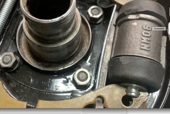
Following installation of the hubs, I noticed that one of them was still encountering some resistance in rotating. Turned out the the raised portion of the hub where the studs are located was ever so slightly touching one edge of the brake cylinder. While I was not happy with my solution, it did solve the problem. This can be seen in video Episode Twelve.

https://vimeo.com/769896299/f92cfe0068

Brake Cylinder Relieved

True to form, when we installed the brake drums on to the hubs we once again encountered resistance to turning! This easy swap to later rear brakes has not been without its challenges. Sure enough, after checking with others on the Sprite Forum it turned out that people did often have to grind down the outside edge of the drums to get them to fit without fouling against the backplate. Whether this is an issue with drum manufacturing tolerances or some other issue – we just don’t know. So, out came the angle grinder with a cut off wheel and we cut some of the drum away and smoothed the edges as best we could. Once again, we aren’t happy with the approach, but also once again, it solved the problem. Everything now rotates freely. The video Episode Twelve shows the process.

https://vimeo.com/769904083/75a1d4a732

After addressing the relocation of the fuel pump from the engine bay to the bulkhead behind the passenger compartment, the installation of a new fuel tank and new fuel pipe, the installation of new rear leaf springs and the cleaning and painting of other rear suspension components, we will return to the installation of the completed axle in the car.

Rear Differential Swap 4.22 to 3.9

A number of Bugeye owners have suggested switching the original 4.22 rear differential for a 3.9 differential from a later Sprite or Midget. We located a 3.9 in North Carolina. We had it checked out by Glenn’s MG in St. Petersburg. He installed a new pinion oil seal and set the pinion pre-load to factory specification. We cleaned up the pumpkin and painted it with silver caliper paint from POR-15. 

The Episode Eight video provides details on the 3.9 differential installation and background.

https://vimeo.com/769556695/420d4bfca6


Removal of Rear Axle – Bigger Brakes and 3.9 Differential

In addition to a general clean-up and painting, it is our intention to replace the original Sprite MK 1 Bugeye rear brake assemblies with later rear brakes from a MG Midget. We had transitioned to disc brakes from a later Sprite or Midget in the front of the car shortly after it was purchased in 1998. The larger rear brakes should provide improved braking in concert with the front discs.

A number of owners had suggested switching out the 4.22 differential that was in the MK 1 Sprite for a later 3.99 diff. Dad was able to locate a good 3.99 in North Carolina so we purchased it. We then had Glenn’s MG in St. Petersburg go through the new diff to ensure it all looked good and we also had him install a new pinion seal and set the pinion pre-load to factory specification. 

New bearings, gaskets, “O” rings, and tab washers will be installed in the hubs. A 1 7/8″ socket is used to remove the axle nuts. One must remember that the LH wheel nut loosens by turning clockwise while the RH wheel nut loosens in a counterclockwise direction. New radius arms were recently installed so they will be removed and then re-used. Bilstein tube shocks were installed several years ago https://valvechatter.com/?p=7674 and they will also be removed and then re-used. The propshaft universal joints will be checked.

The handbrake cable must be disconnected and the connecting rods were removed as new adjustable rods are required with the later MG rear brakes. The rubber rebound straps  were removed and will be replaced with new straps. 

The half shafts were replaced a number of years ago with hardened steel shafts. They will be re-used. 

The Episode Seven video is rather long but it details the removal of the rear axle and all of its related components. https://vimeo.com/745178474/88a9f43bba


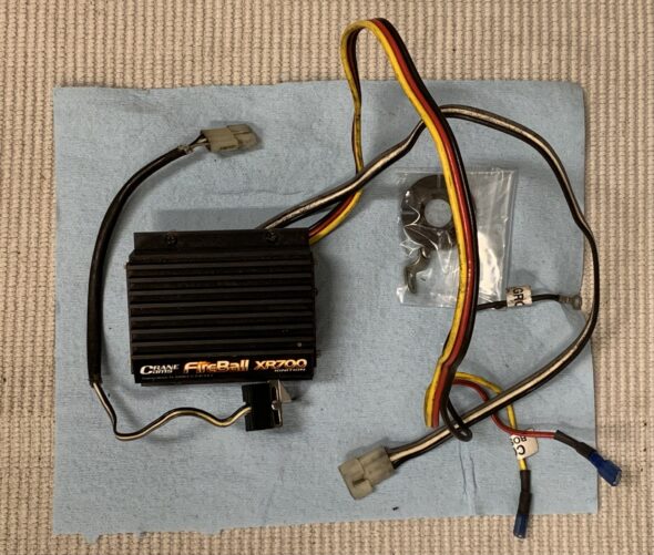
Removing the Crane XR700 Ignition Module

Having made the decision, for at least the time being, to revert to the original Lucas 25D distributor that is being rebuilt by Jeff Schlemmer at Advanced Distributors we went ahead and removed the Crane XR700 Fireball electronic ignition module from the car. The Episode Six video shows the removal of the unit and provides information on the wiring connections from the Crane module to the ignition coil and the distributor.

https://vimeo.com/744803932/e7aaba6adb

Ignition Timing Pointer

Trying to use a timing light to set ignition timing is extremely difficult on the Bugeye given that the pointer on the timing cover used for alignment with the notch on the crank pulley is at the bottom of the engine.

Tom Colby at Speedwell Engineering makes a stainless steel pointer that can be used to move the timing process to the top of the pulley. More information about the kit and its installation can be found in this post under the Personalizations posts: https://valvechatter.com/?p=13529