
Axle Install – This process has taken longer than expected but it is now time to reinstall the prop shaft, the rear axle, the new fuel tank and to connect the fuel delivery lines. Installing the prop shaft can be a bit of a struggle because of the flexible front yoke, but it was much easier with the axle and fuel tank out of the way. A clear look at the target (rear of the gearbox) is possible with the axle out of the way. The Episode Twenty video shows the quick job of the prop shaft install: https://vimeo.com/770233750/3412849430
Details of the installation process of these components is provided below. However, the Episode Twenty-One video also summarizes the installation: https://vimeo.com/770295832/305b6fdd14
Before reinstalling the axle into the car, we needed to install the axle brake pipe securing straps to the axle housing. These were not on the car when we acquired it, but the brass straps, which are very similar to the original straps, can be purchased from Moss motors. These are easy to install. One first loops the strap around the brake pipe and then around the axle housing. There is one for each side of the axle.
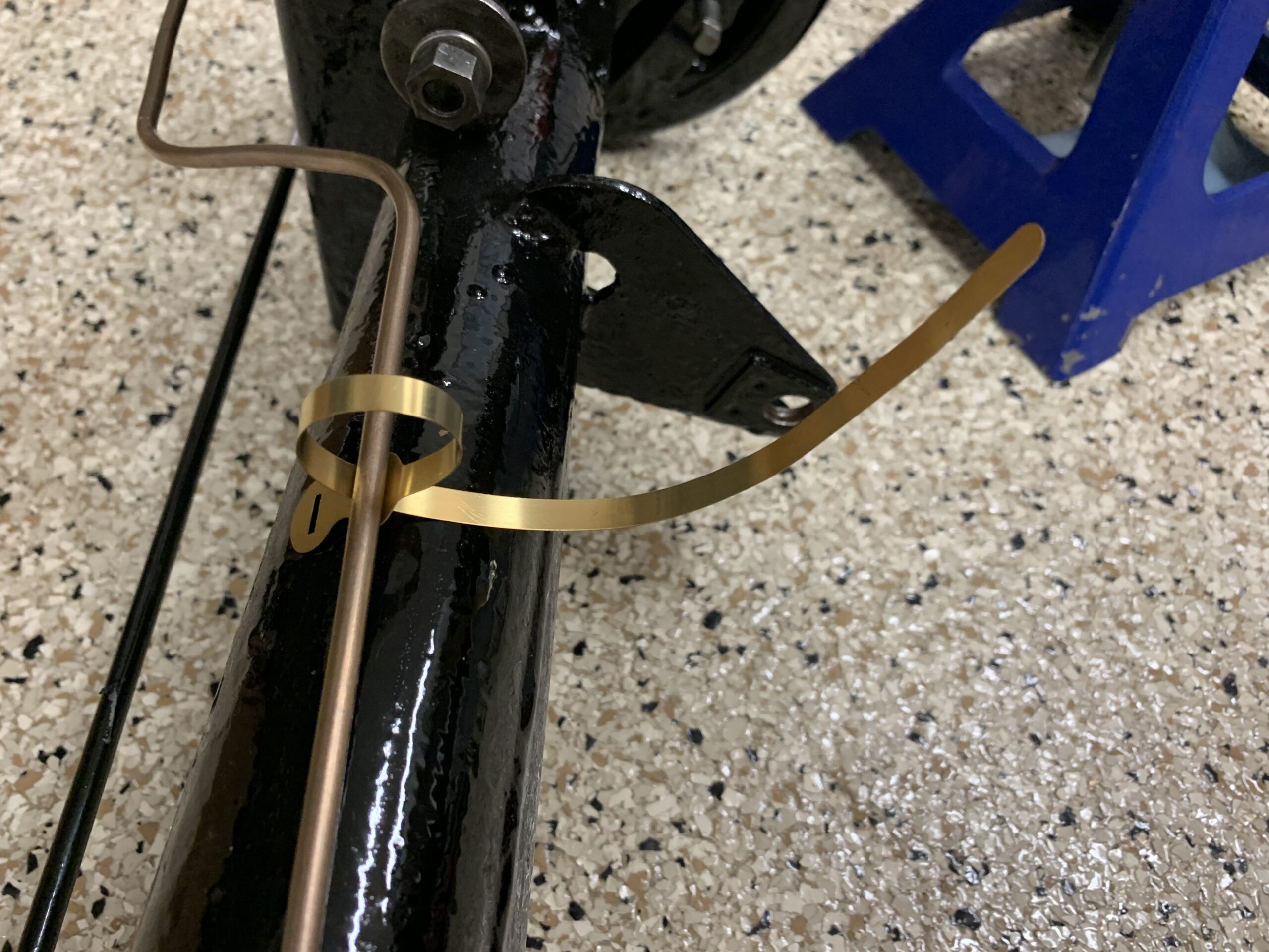
Brake Pipe Axle Straps
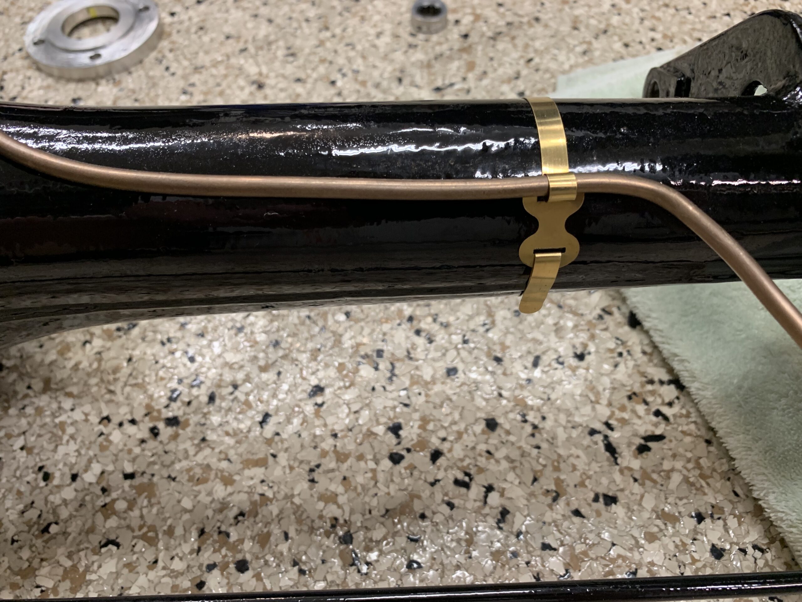
Axle Straps Installed
Garage assistant Fiona, using the floor jack, lifted the rear axle and pushed it forward under the car.
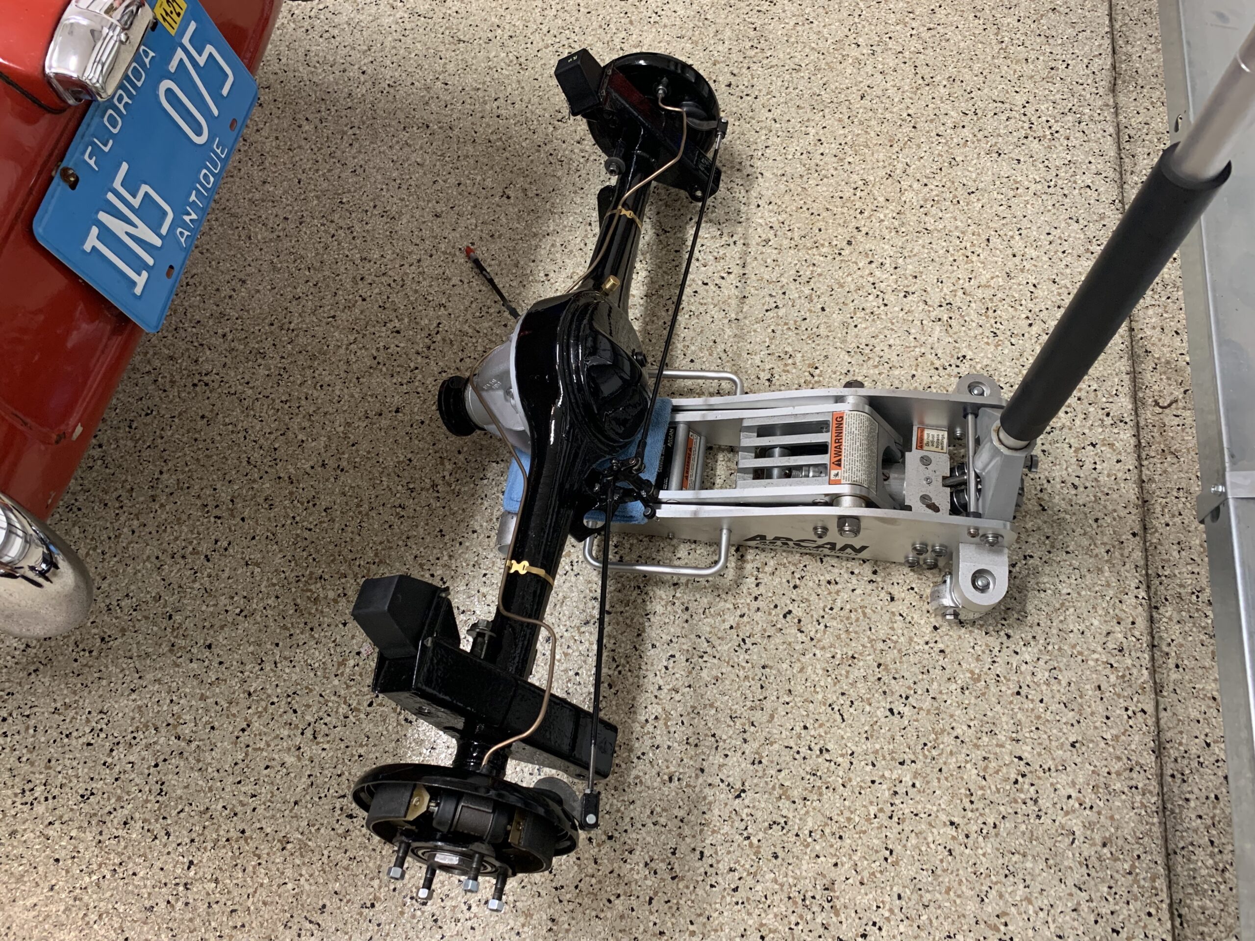
Axle on Floor Jack
After a little manipulation we were able to put the special bolts for the spring eyes and for the radius arms into position and secure with nylock nuts. Works best to install the radius arm bolts first, then leaf spring eye bolts. Nothing was tightened completely and won’t be until the car is on the ground.

Axle in Place
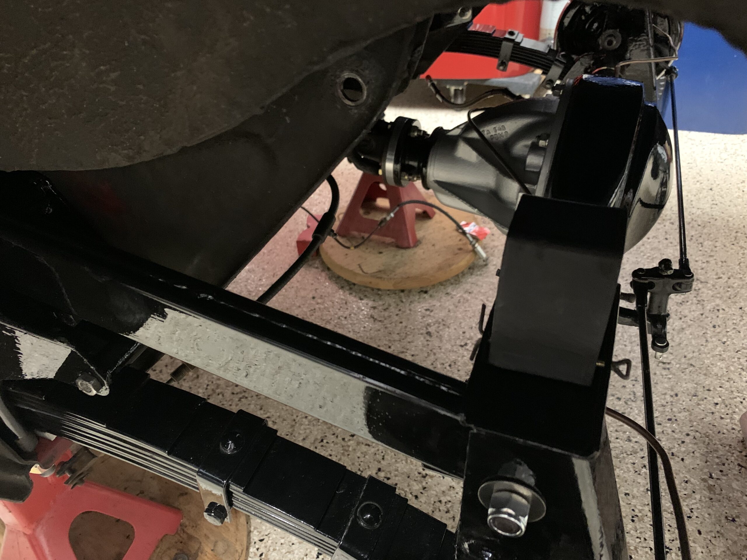
Connecting Axle to Suspension
We were then able to install the prop shaft spacer onto the end of the unit and attached it to the rear differential with grade 8 5/16” x 24 x 1 1/2” bolts with nylock nuts.
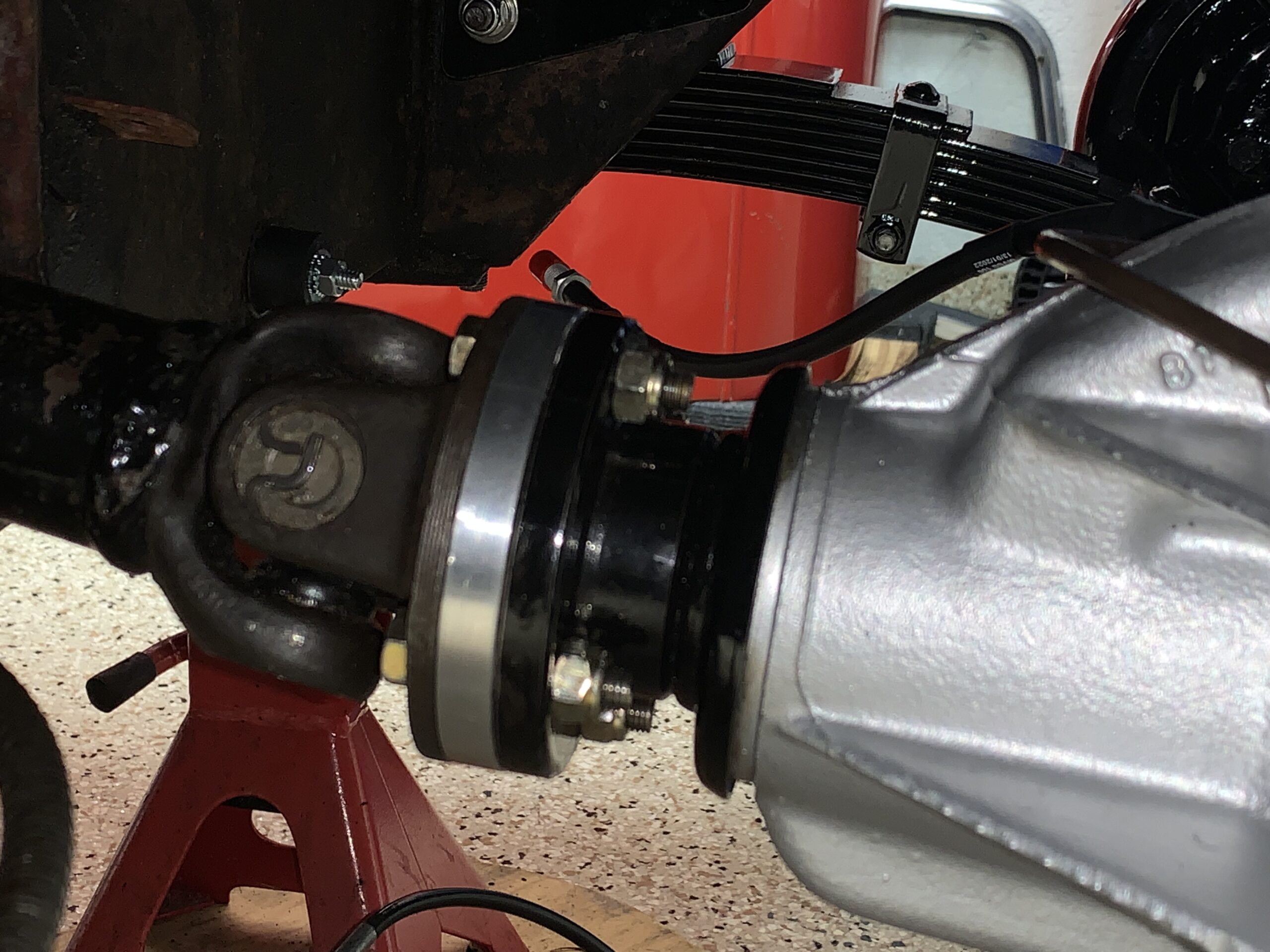
Prop shaft spacer
Just so we wouldn’t forget we went ahead and tightened the axle assembly nuts to 140 foot pounds of torque. We then bent the tab washer down over one facet of the nut.
Axle Nut Torqued to 140 ft. lbs.

Locking Tab Washer Folded Over the Nut
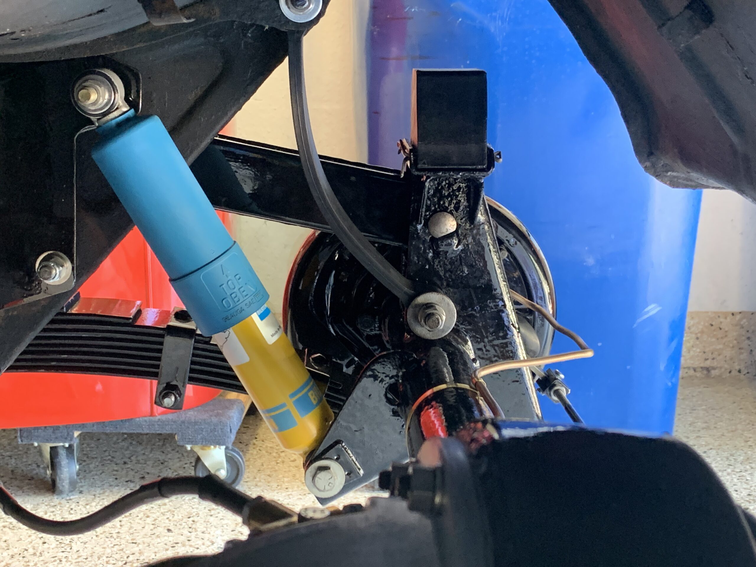
Bilstein Shock Install – Our next step is to install the rear Bilstein tube shocks. The lower mounting bolts are ⅜”-24 with 9/16” hex heads. Note the spacer on the lower mount must be in the hole properly before tightening down the assembly. With the original leaf springs we had the lower mount bolt head closest to the springs and the nut closest to the differential, however, with these new springs the shackle for the springs conflicts with the bolt and makes it almost impossible to insert it into the mounting point. So we just switched the direction.
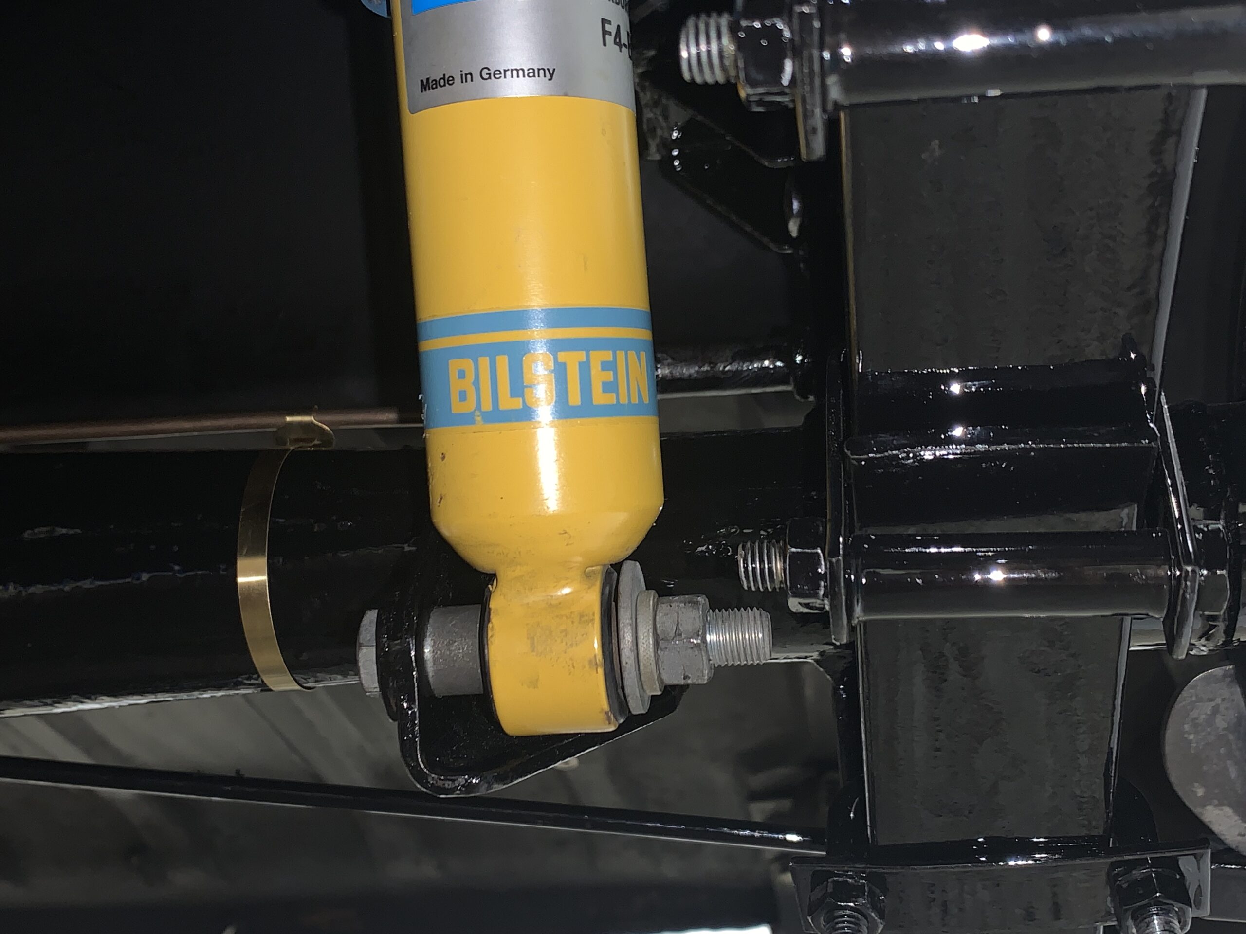
Lower Shock Mount
Upper Shock Mount
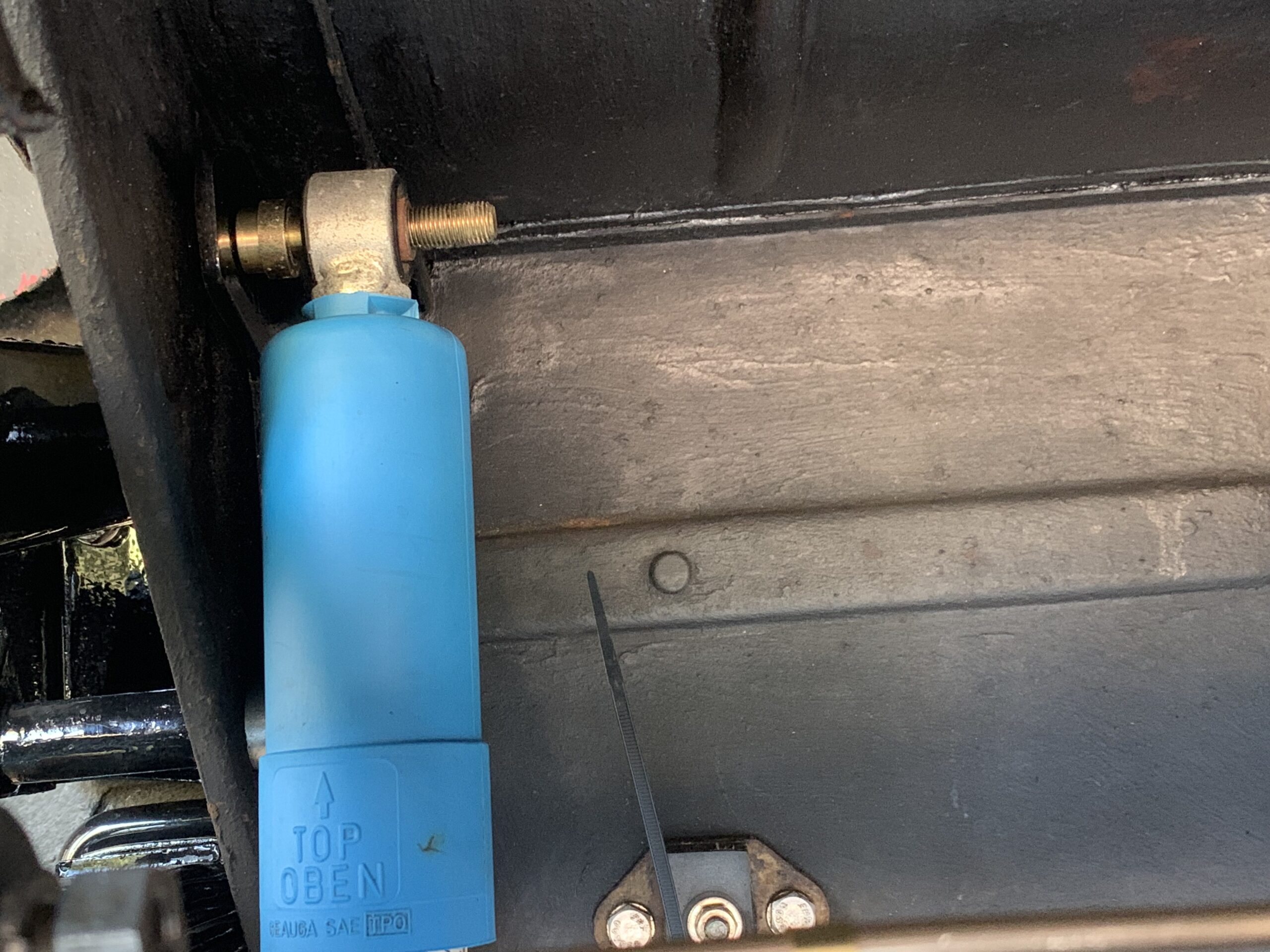
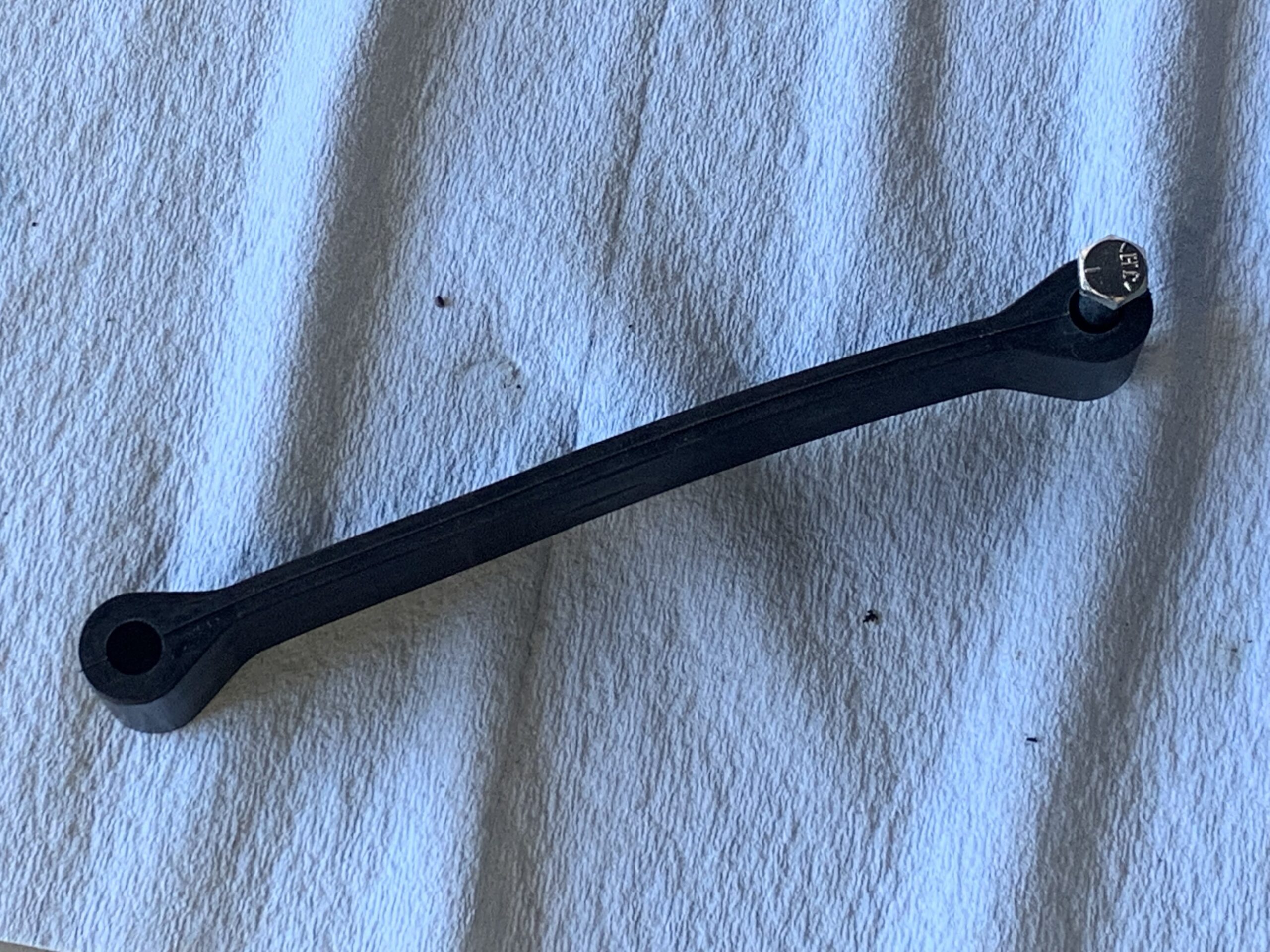
Rebound Straps – Next, is the installation of the rear axle rebound straps. New straps from Moss Motors are used. The top bolt is a ⅜”-24 x 1 ¼”. The lower mount is a ⅜”-24 stud affixed to the axle casing.
New Rebound Straps
New Rebound Straps Installed
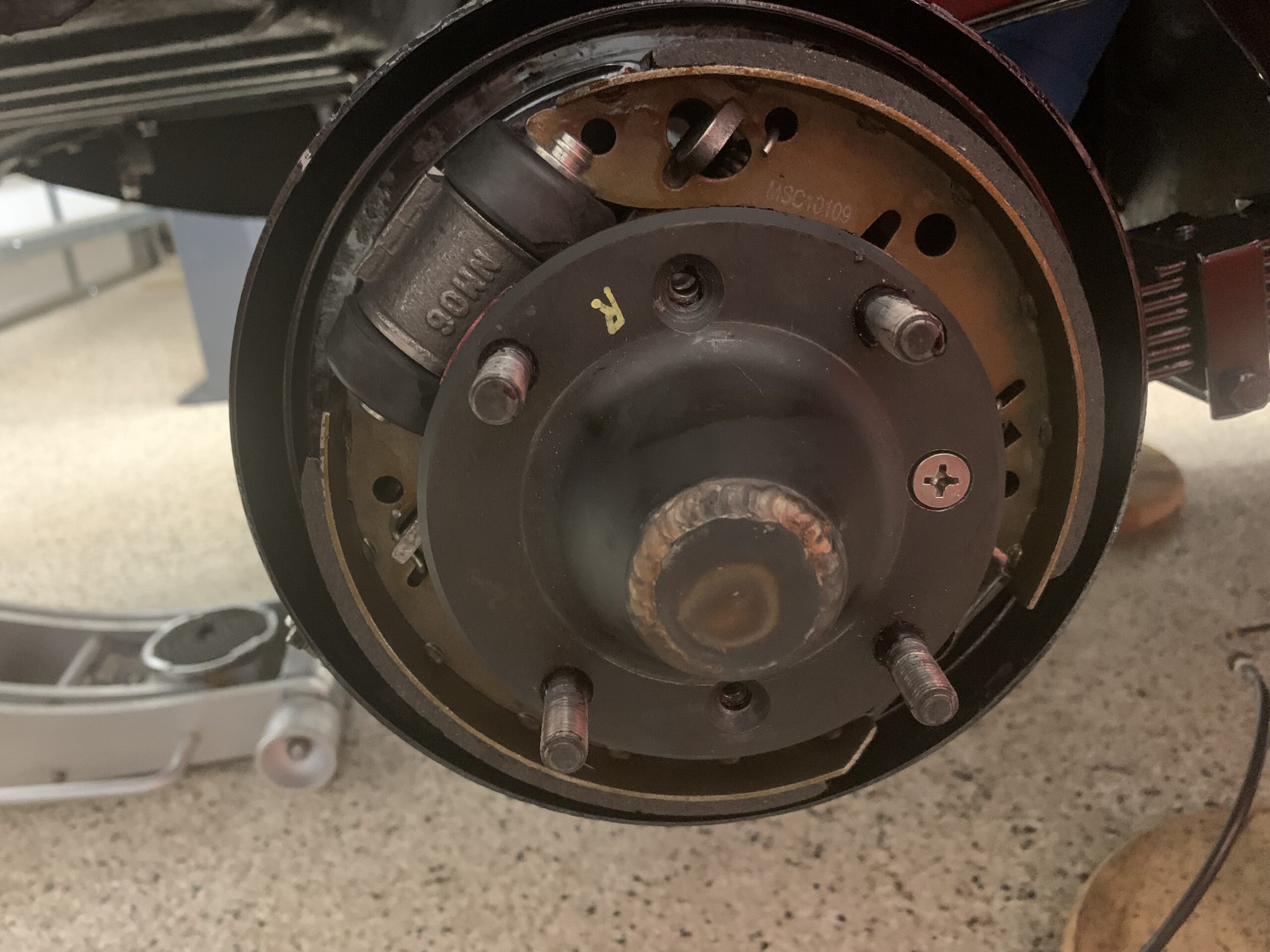
Hub Seals – After bending down the locking washer tab on the axle nut, a new rubber “O” ring was pressed into its hub cavity.
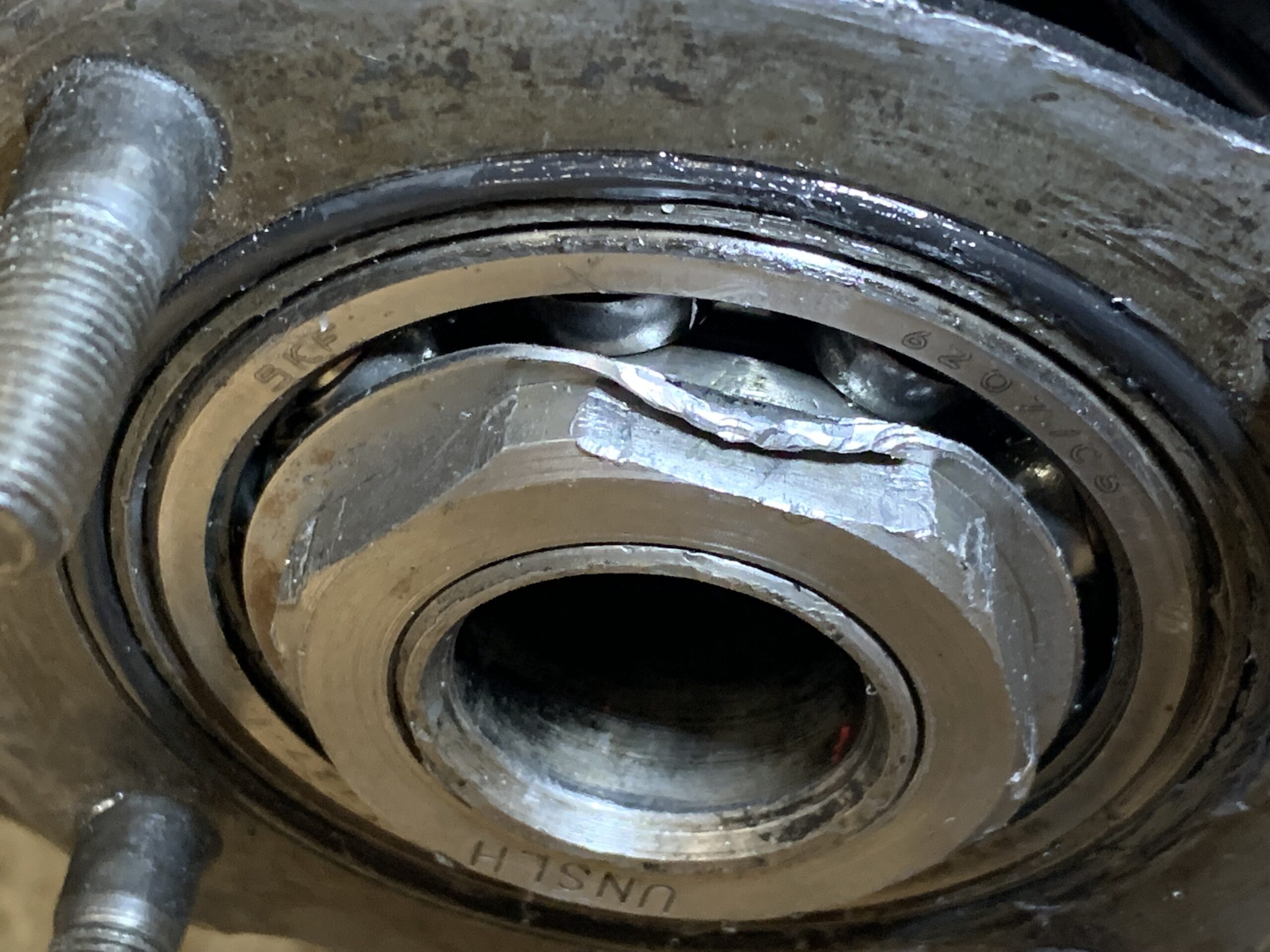
Rubber “O” ring Installed in Hub
Followed by the paper gasket which was coated with Permatex high tack gasket sealant on both sides before installing the axle half shaft. This sealant was recommended by Mini Mania and was used in their YouTube video of the Sprite rear axle assembly.

Permatex Sealant
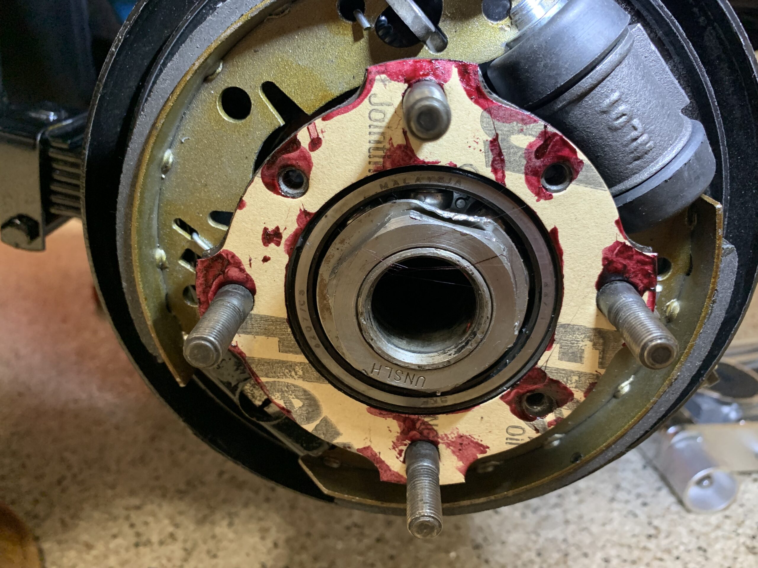
Paper gasket installed with Permatex High Tach on both sides
We then installed the axle half shaft and quickly screwed in one of the countersunk pozi drive screws into the axle hub.
Axle Half-shaft Installed
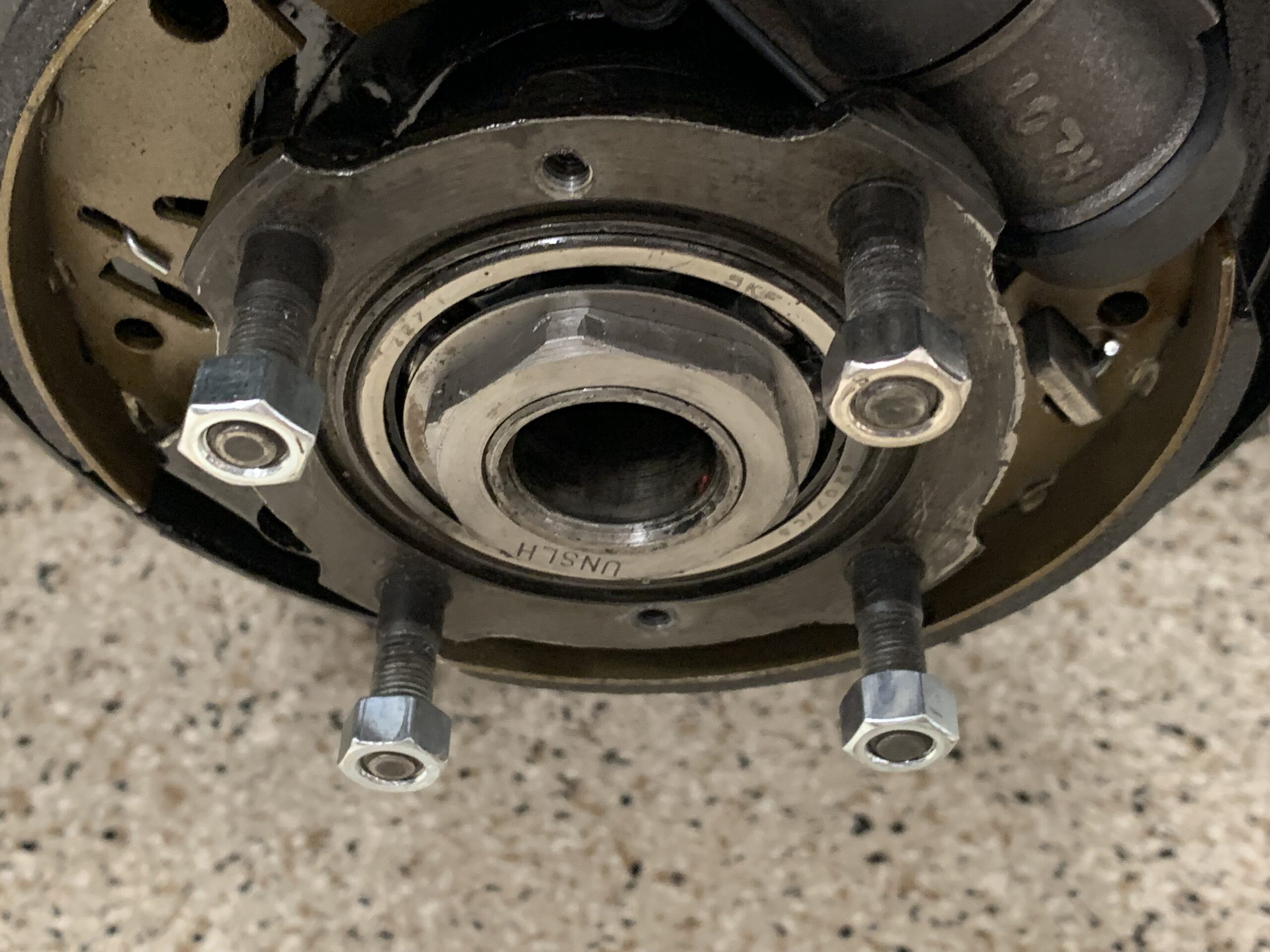
Brake Drum – We then installed the brake drum and screwed in two of the pozi drive screws through the brake drum into the axle half shaft and the hub. Those screws were tightened as tight as possible and then we installed four hub nuts on the hub studs and tightened those. I could then re-tighten the two screws. That should give us a good seal.
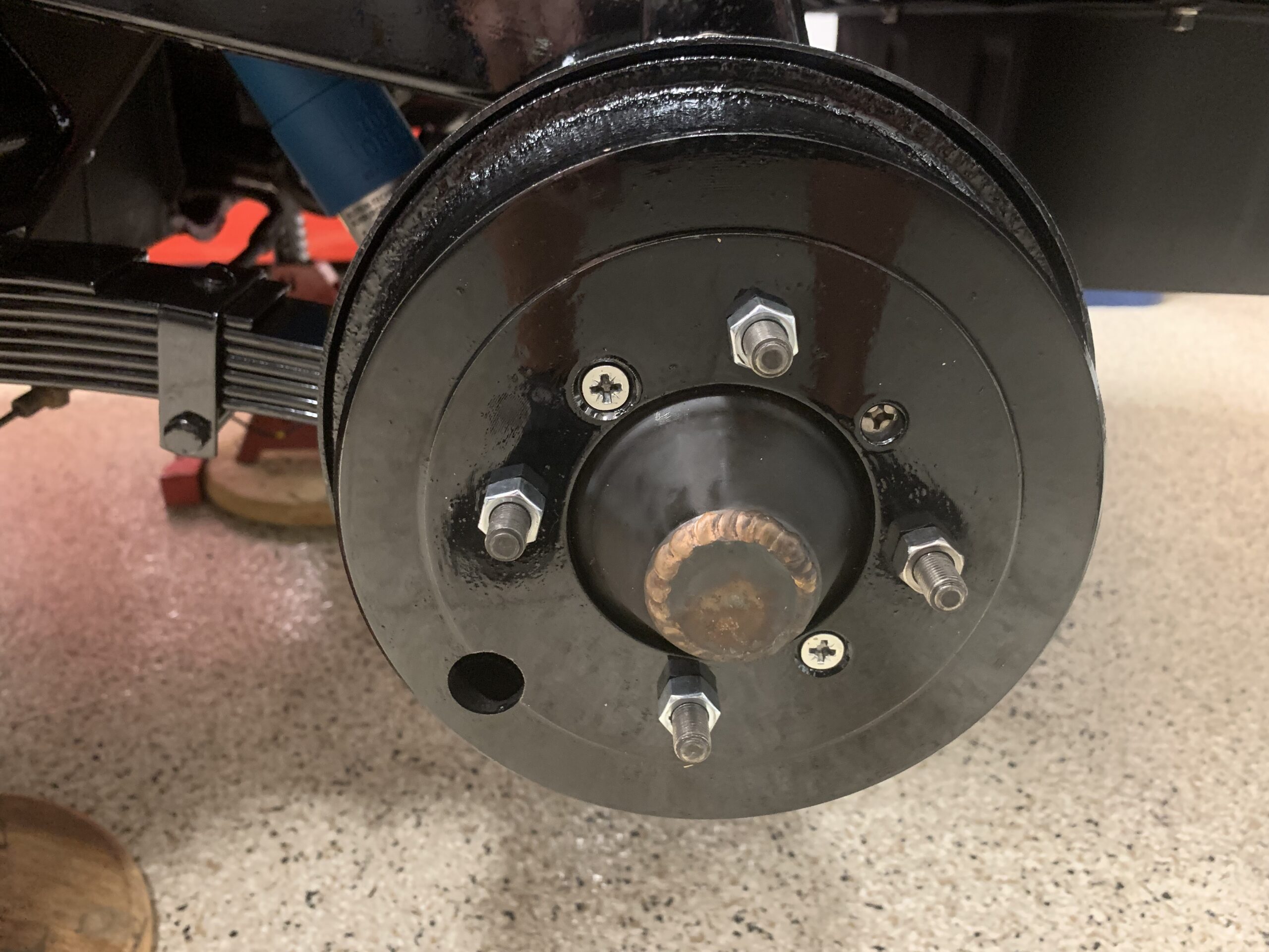
Brake Hubs Installed
That completed the axle work for the time being so we reinstalled the fuel tank being careful to connect the power wire to the fuel tank sender. This was a quick and easy job.
Fuel Pipe – We then installed the fuel pick up line from the front of the tank over the axle and to the new location for the SU fuel pump.

Fuel Pipe from Tank to Pump

Fuel Pipe to Pump
Reconnect handbrake cable at rear axle, fill rear Differential with oil and install fuel tank filler pipe – We reconnected the handbrake cable in the same position that it was prior to disassembly. 15/16″ of threads showing. We will ultimately replace the handbrake cable with a new one, so this is just temporary and of course we will need to adjust the shoes in the brakes and then adjust the handbrake tension.
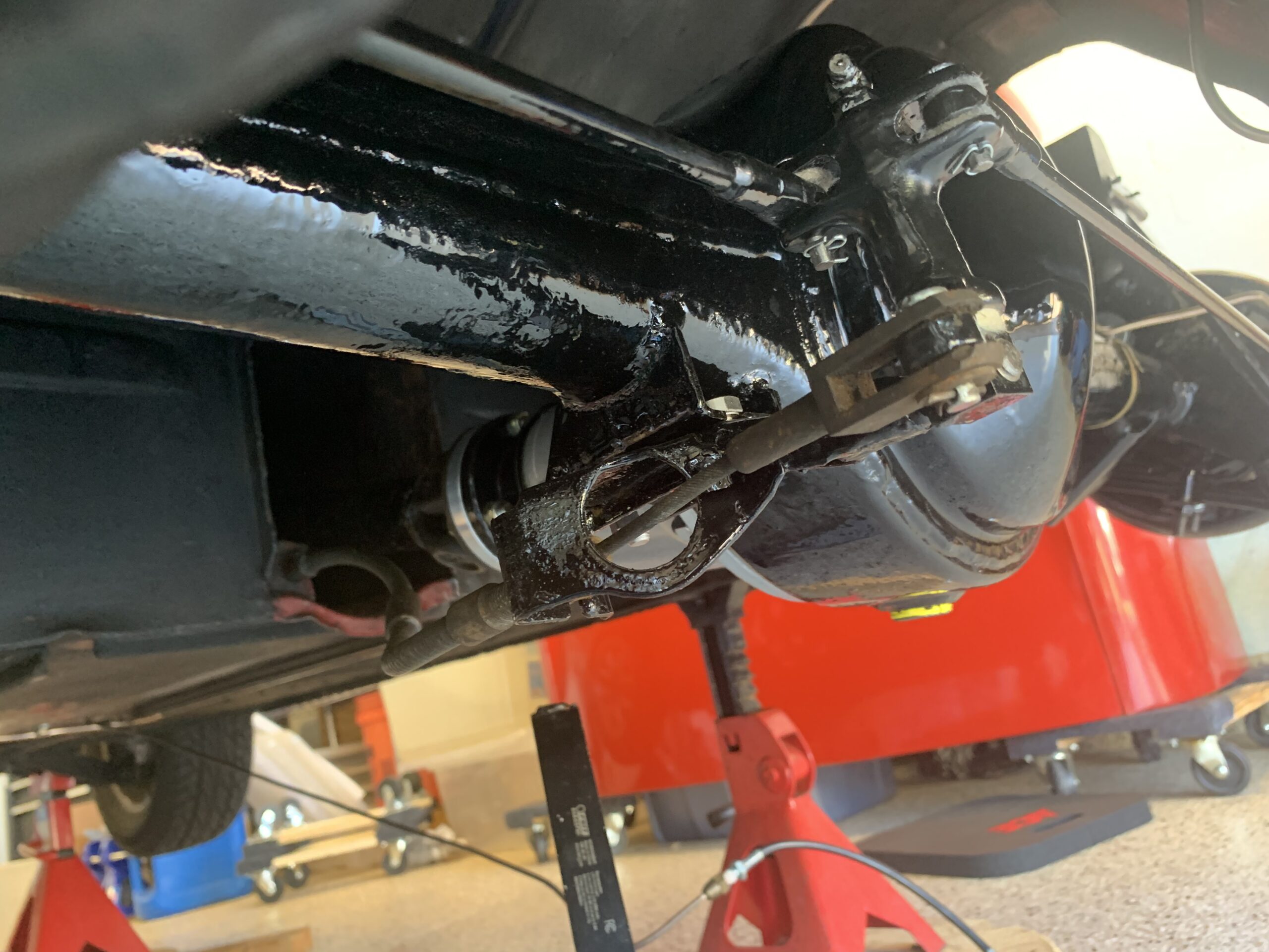
Handbrake Cable Connection to Lever
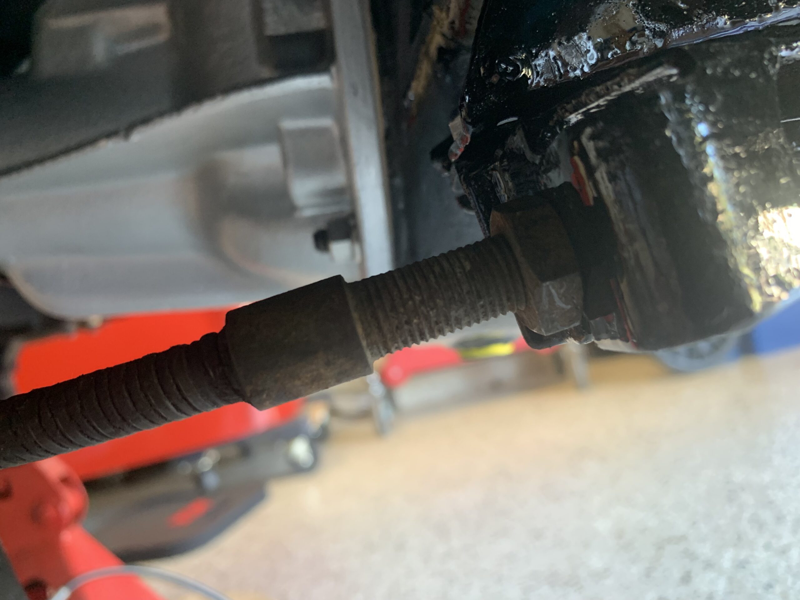
Thread Runout on Handbrake Cable
We then filled the rear differential with just under 1 quart of MT 90 gear oil. The Red Line MT 90 product is a 75W – 90 synthetic G4 gear oil. We used a syringe to push the oil into the filler plug hole until it just starts to drip out of the hole then installed the filler plug
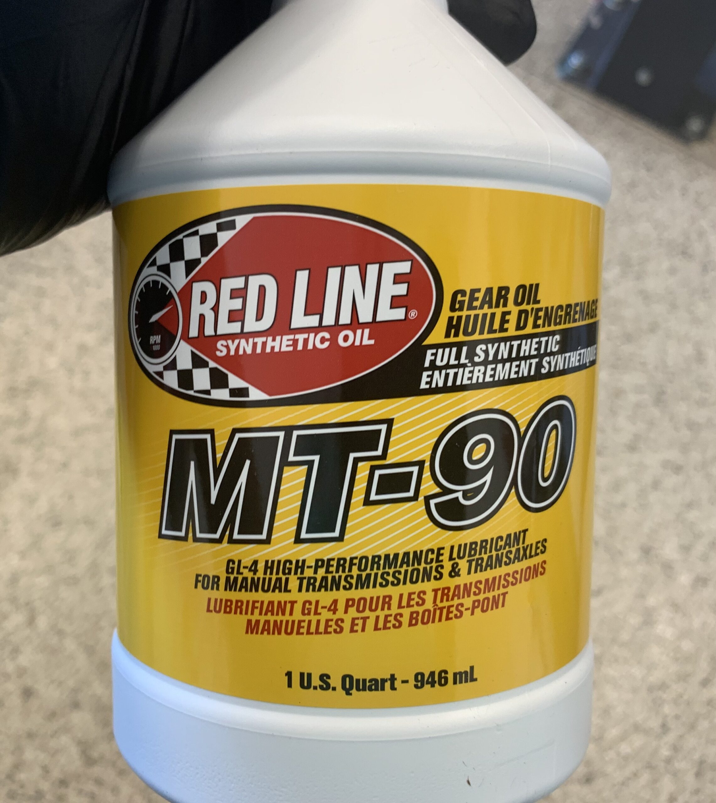
Red Line MT-90
Fuel Tank Filler Pipe Install – As stated previously, the original fuel tank for the Bugeye had the filler pipe welded to the tank as one piece. The Bugeyeguy supplied fuel tank has a separate filler pipe which is joined to the tank with a rubber collar and two hose clamps.
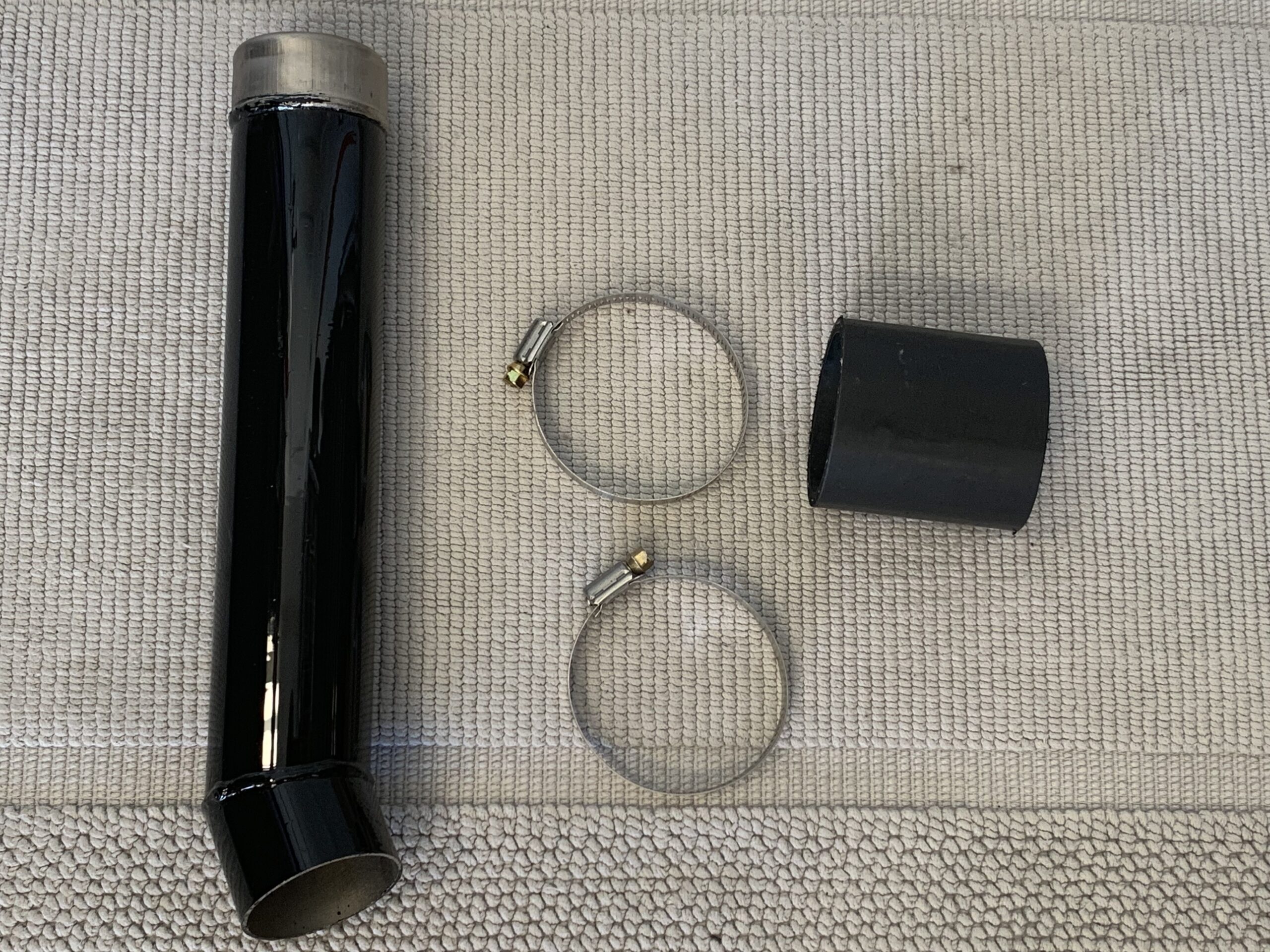
Fuel Filler Pipe, Rubber Sleeve and Clamps
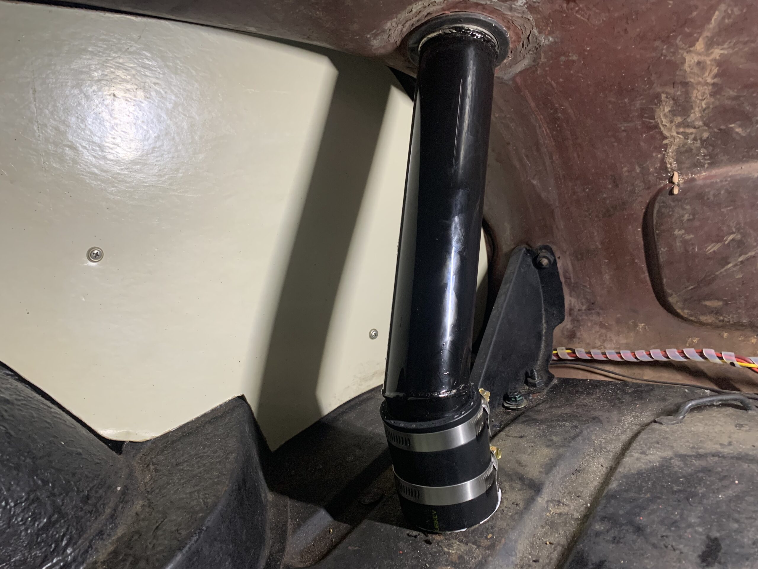
Fuel Filler Pipe Installed
We were finally able to get the car off the jack stands and onto the ground. Now it is time to move to the front suspension.

Finally, Back on its Tires
Finishing Up the fuel delivery and Suspension – We got the Bugeye up on the lift on November 17 to make it easy to tighten all of the fasteners associated with the rear suspension. We also added a fuel filter in the hose from the fuel tank to the fuel pump.
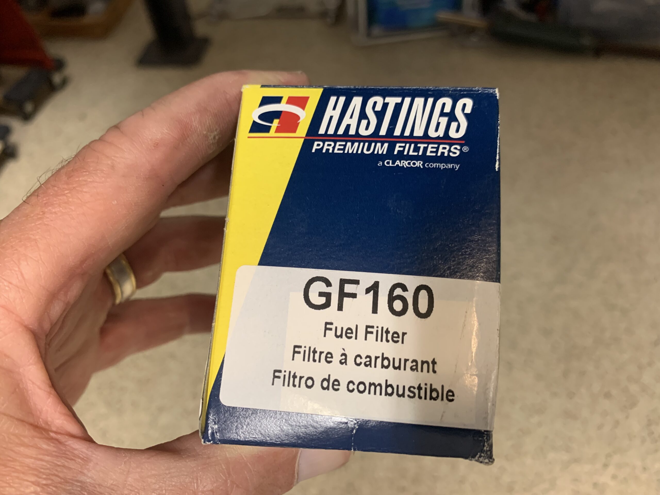
Hastings Fuel Filter GF160
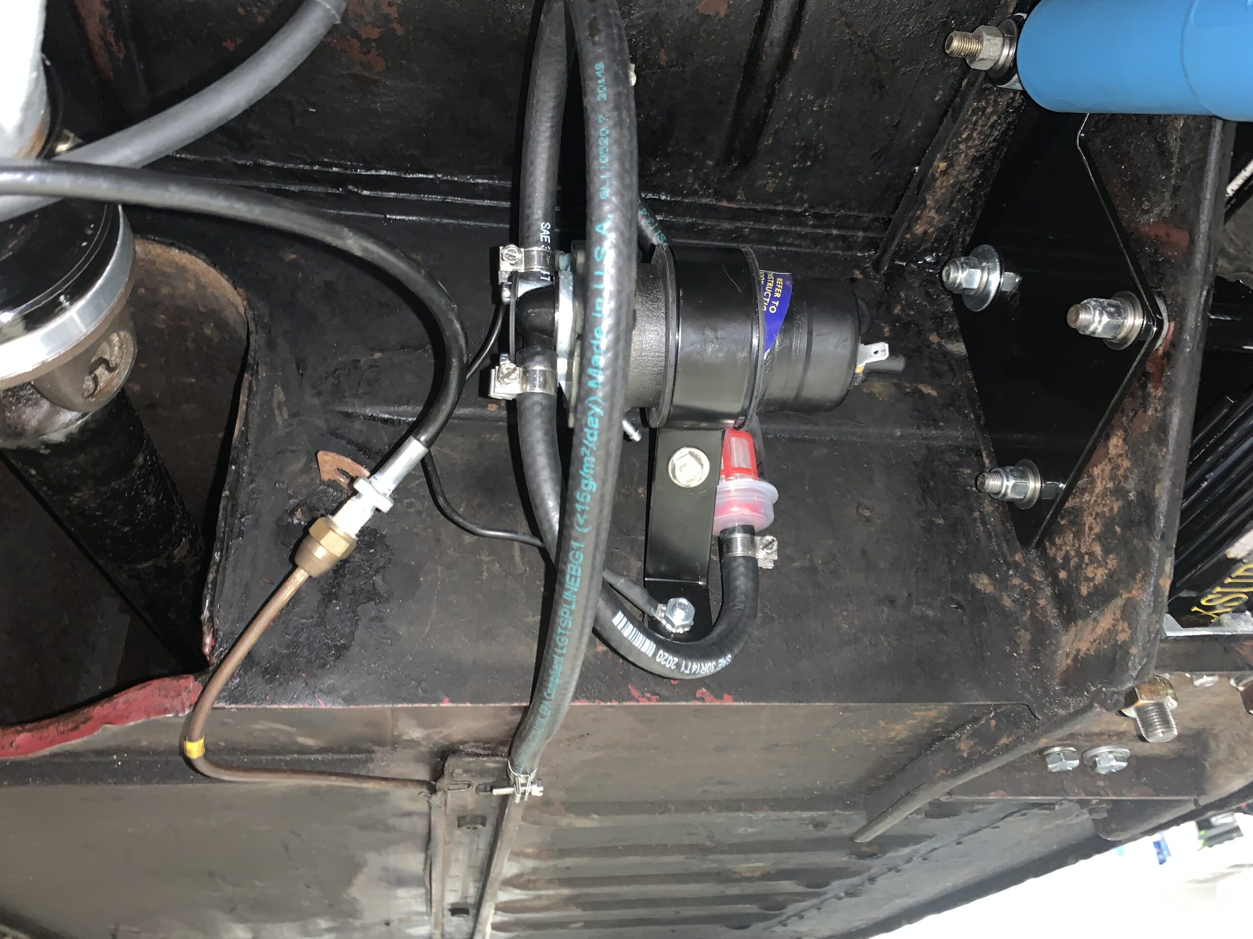
Fuel Filter, Pump and hoses
Video Episode Twenty-three shows the work done in finishing the suspension and fuel delivery systems: https://vimeo.com/773027554/131aff730b
Temporary power to the fuel pump – We will address a permanent solution to routing an electrical wire to the fuel pump when we work on a new wiring harness. As a temporary solution to test the fuel delivery system to the carburetors, we simply ran a wire from the switched side of the fuse panel, through the firewall, along the RH seat rail and through the seat belt bolt hole in the interior floor to the fuel pump. To accomplish this we went ahead and removed the RH side front interior kick panel and front carpet.