December 28, 2001
To get started with my restoration, the first thing I had to do was move the car from its storage site to its new home. This required putting some new rubber on the wheels as all four of the tires were flat. I purchased some Michelin tubes from Hendrix Wire Wheel and one of the local tire shops mounted four used tires on my old wire wheels for me for free. After installation the car was rolling and ready to be towed to our home and into a storage shed I purchased.
February 2, 2002
My son, Scott, assisted me in the relocation process. The car looked pretty rough. Obviously the garage had been damp as considerable rust had developed. Once home, the dismantling process began.
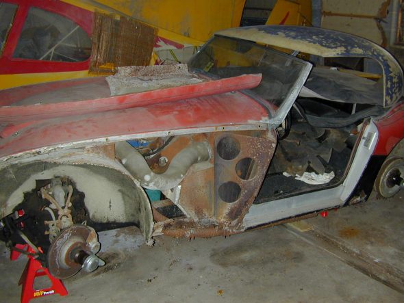
Stored in a poultry barn
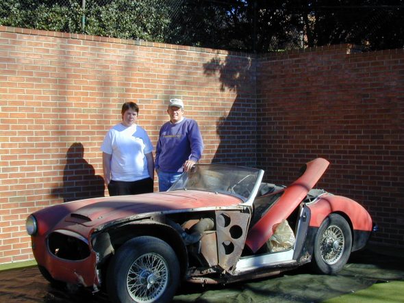
Off the trailer at home with Scott
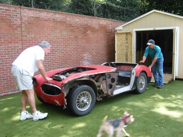
Bringing the Healey Home
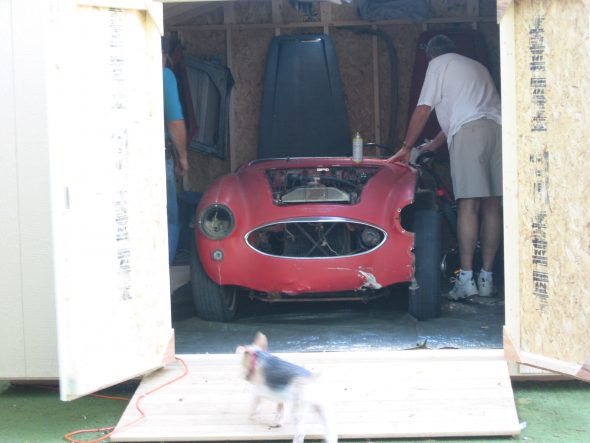
Tucked into the shed
March 15, 2002
Rear Bumper
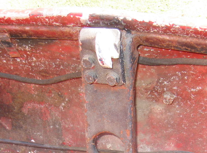
Removed two bolts (HZS0608) each, with flat and split washers, from the brackets in the boot for the rear bumper bars (RH-17H9699) and (LH-17H9700) . Note that one of the bolts also secures the ground cable (1B9078) from the battery master switch (1B2804) to earth.
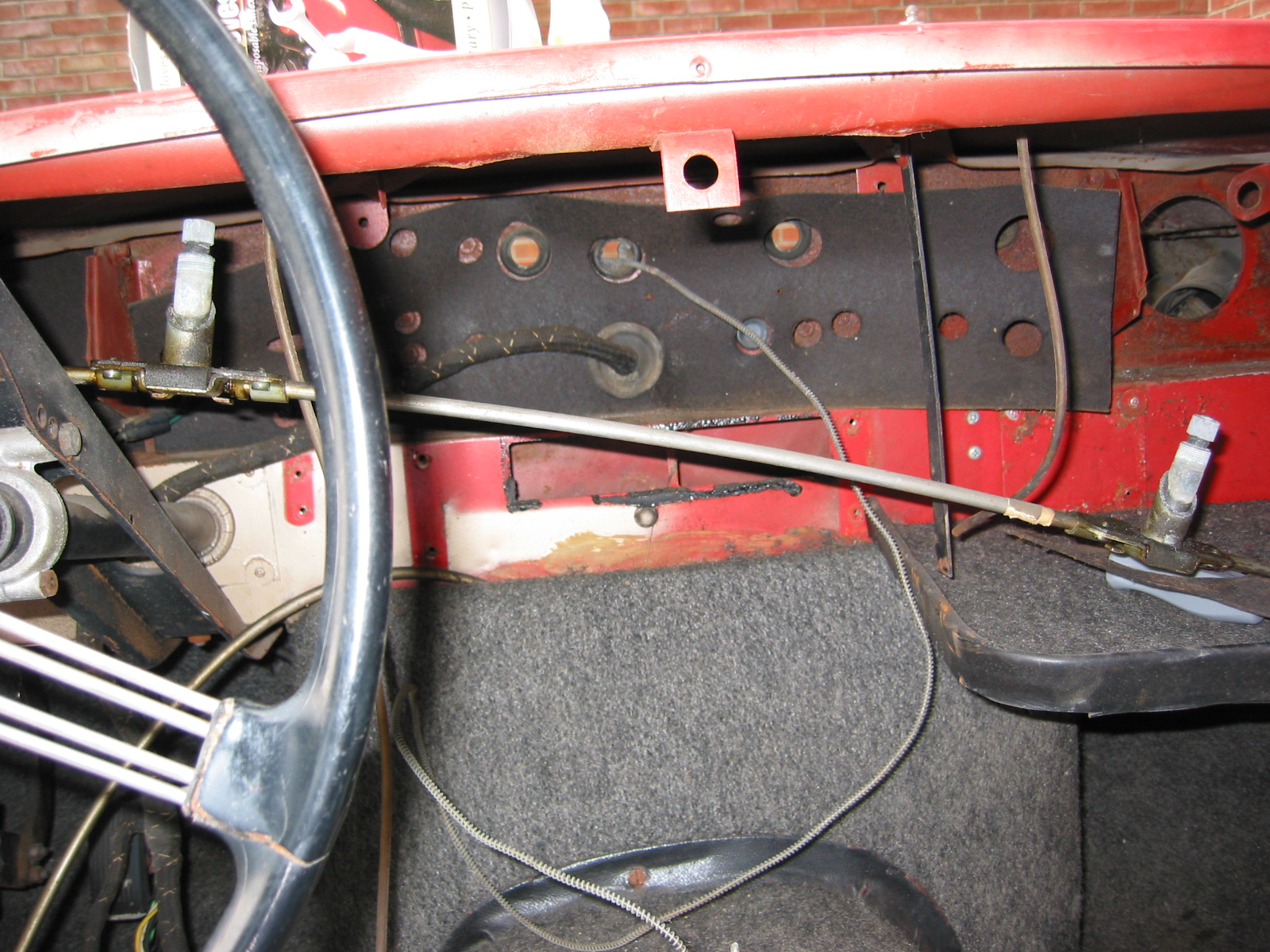
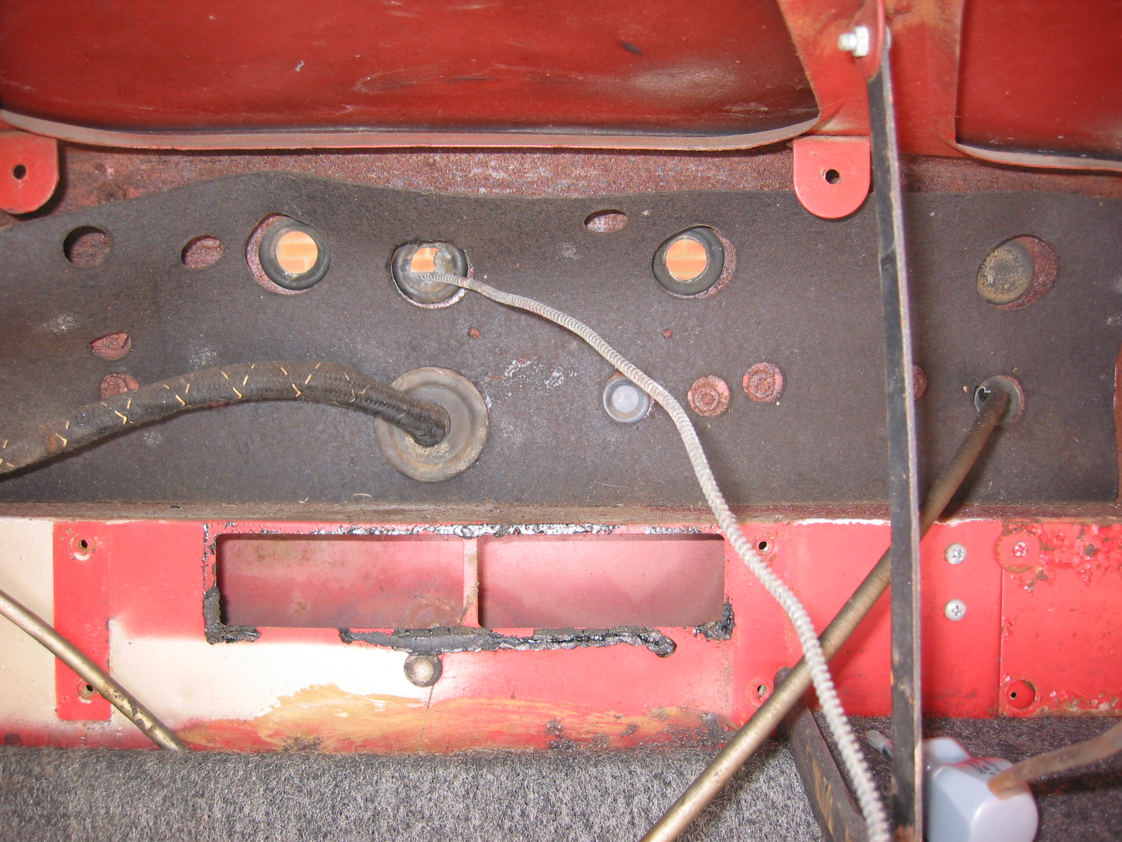
Rear Bumper Bracket Mounting Points
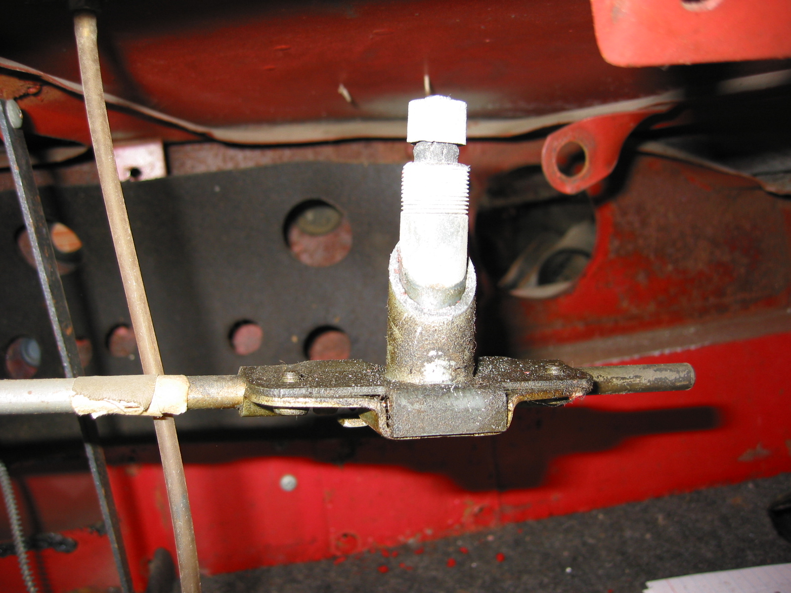
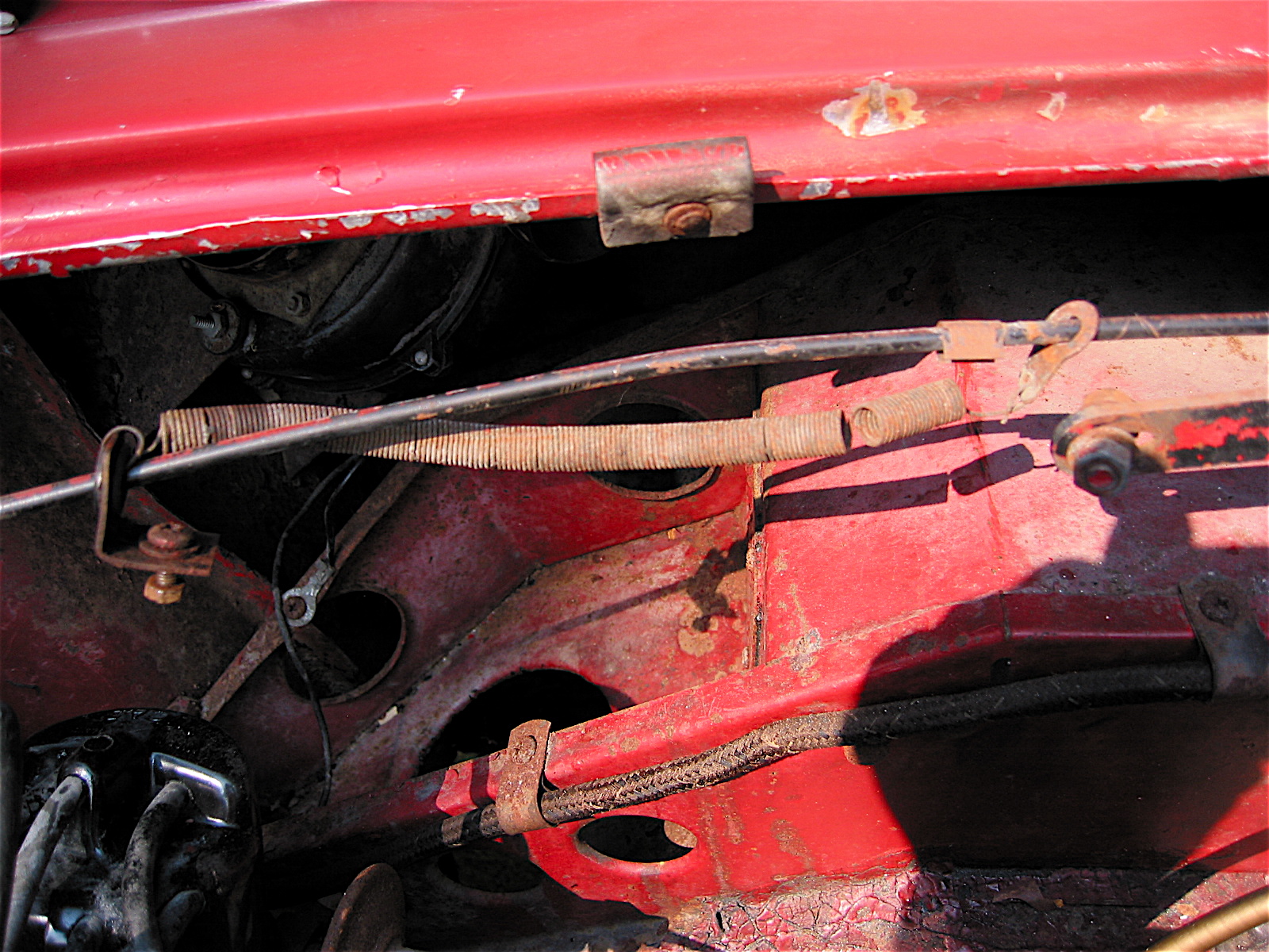
Boot Lid Control Cable
Removed the boot lid control cable (14B8692). Secured at the boot lid hinge stud with a flat washer and nylock nut (53K1661), and by a bolt (PMZ0410), lock and flat washer and nut at at the prop rod support bracket (14B6467).
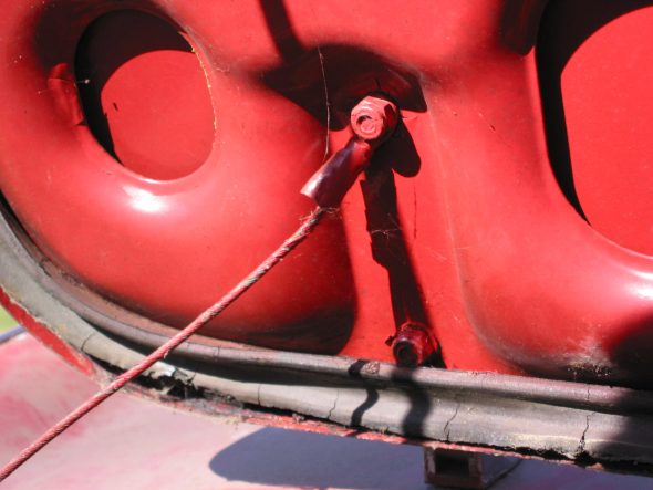
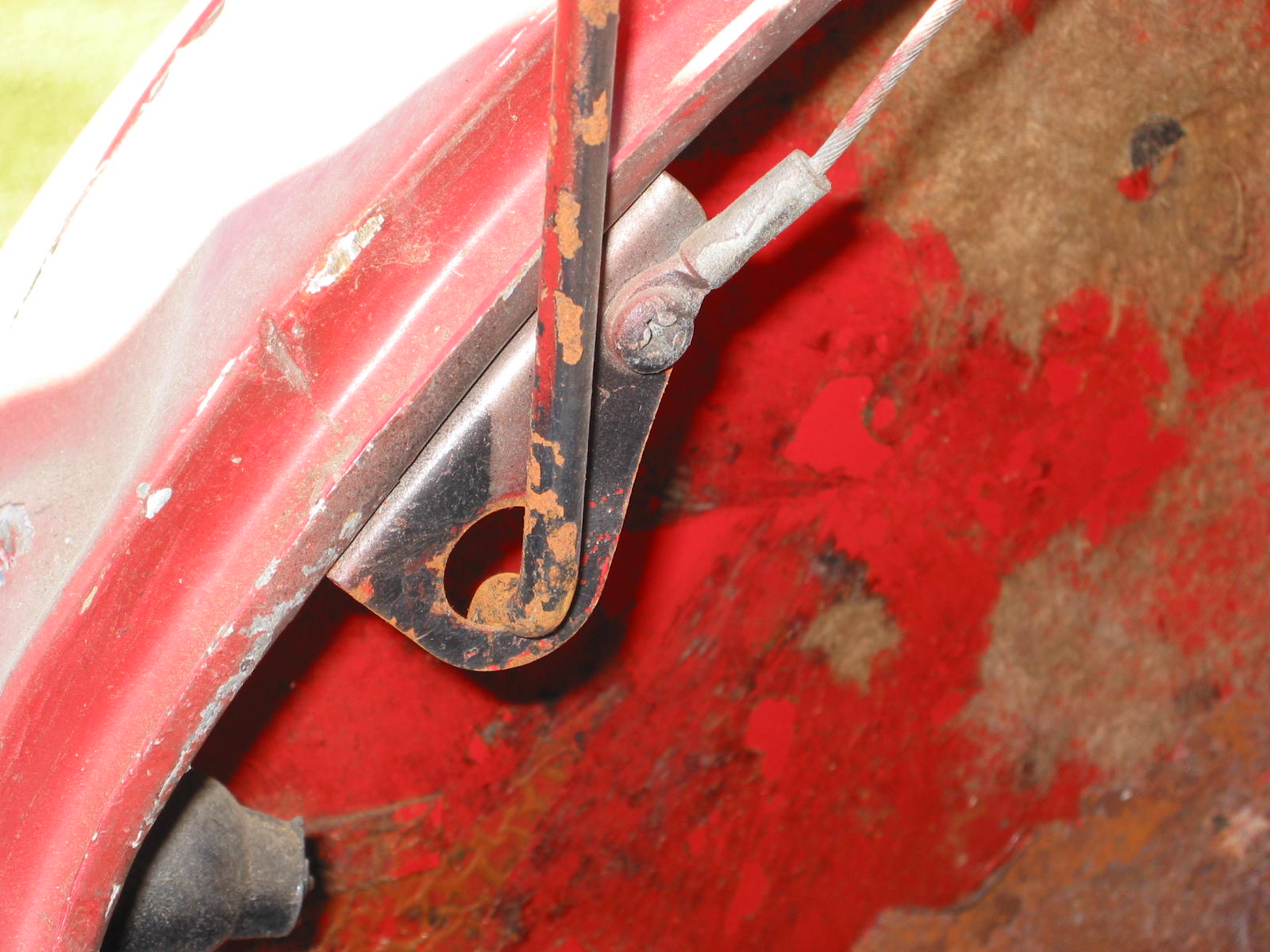
Boot Lid Control Cable fixing to boot lid
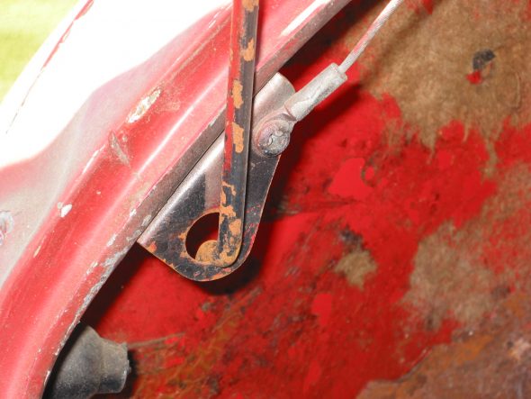
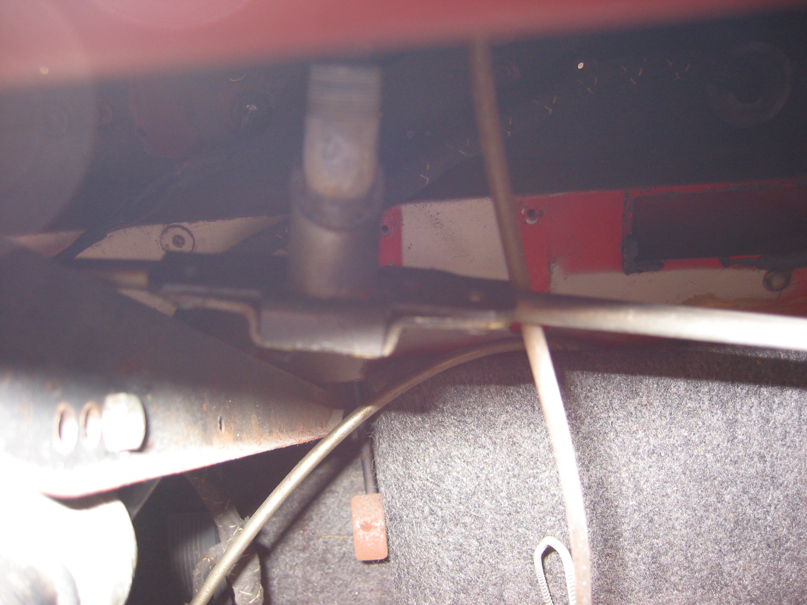
Prop Rod Support Bracket
Boot Lid
Hinges should be loosened from the rear shroud first, then the boot lid. This because the shroud is soft aluminum while the boor lid is steel. The RH hinge (14B1725) and the LH hinge (14B1726). The hinges are handed but their gaskets comprised of two parts each (14B3463) and (14B3462) are not. Removed three nyloc nuts (53K1661) with flat washers for each hinge. Unlocking the boot lock handle assembly (14B1963) will then allow removal of the boot lid from the car.
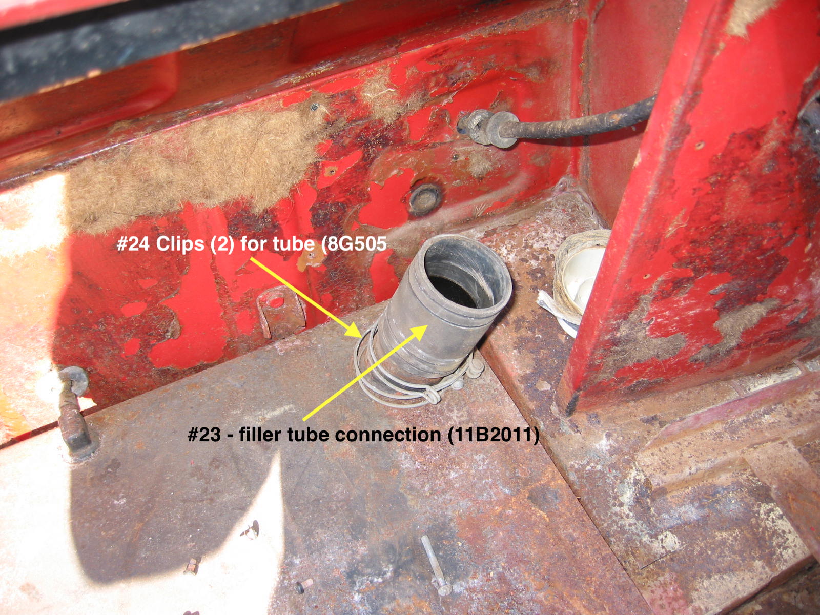
Fuel Tank Filler Pipe
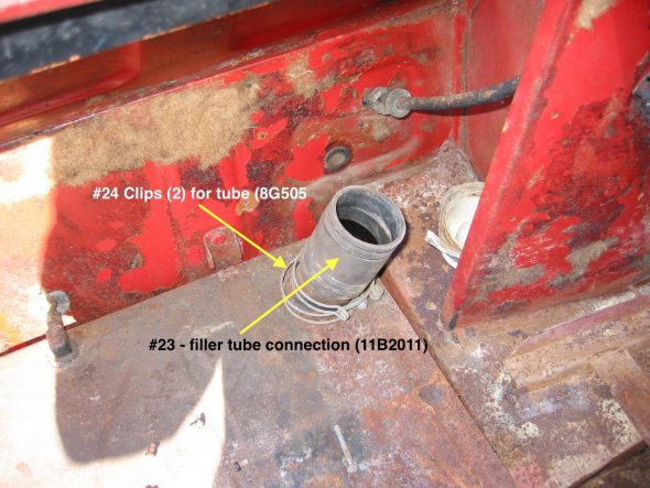
Removed fuel filler cap (8G654) from the tank filler pipe (AHB8315). I then loosened the two tube clips (8G505) on the short filler tube connection (11B2011) and pulled the steel filler tube with its rubber tube to body collar (11G2100) out of the rear shroud and removed both.
Fuel Tank Fittings
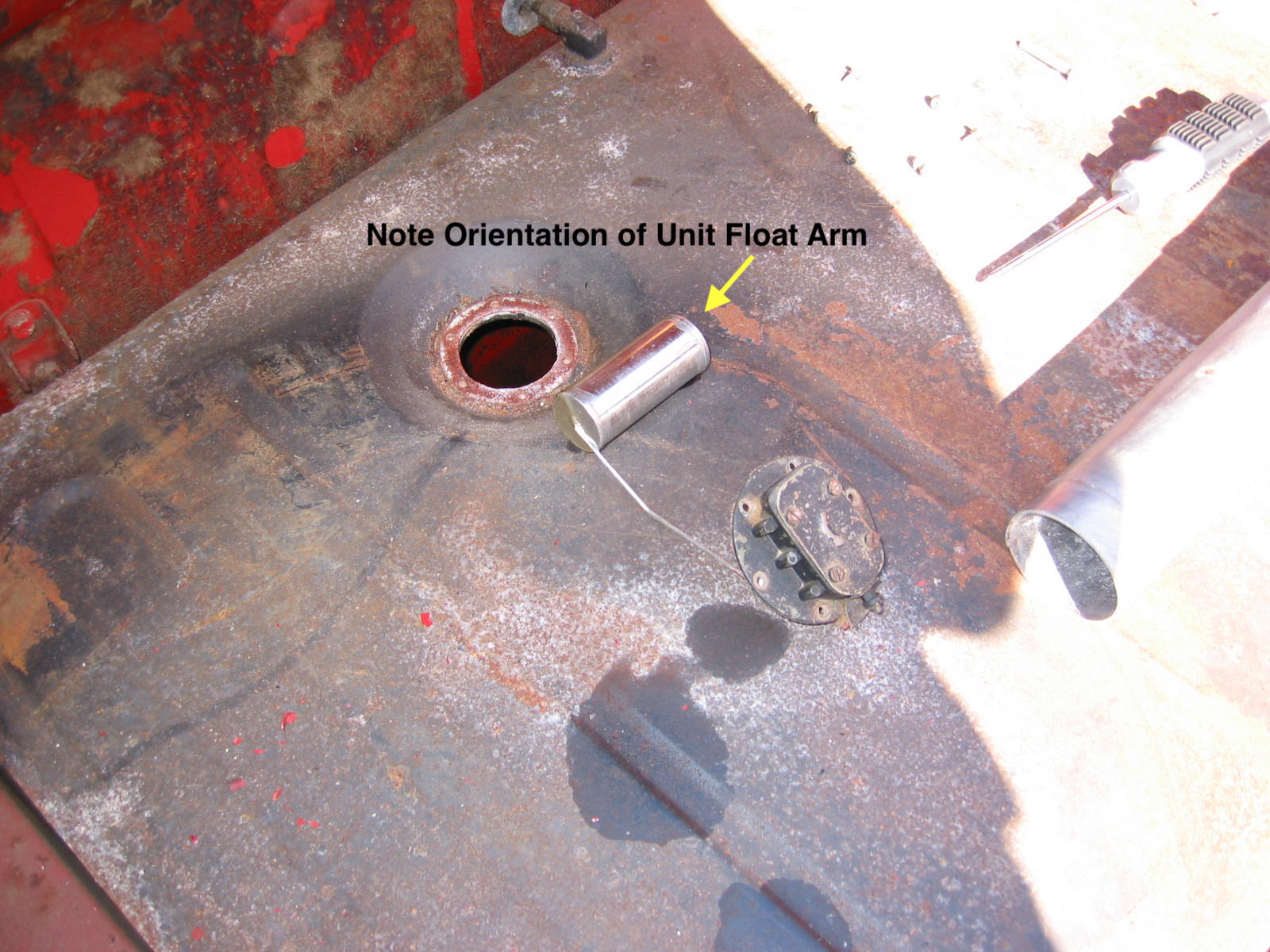
Fuel Tank Sender Unit
Removed the Fuel Gauge Tank Sender Unit (1B2736) by removing six screws (53K165) fixing the unit to the tank. Each screw had a copper washer (2A2088). A cork gasket, or tank unit washer, (2H1082) was also removed. Note that the float arm points to the top of the front of the tank/car. I disconnected the electrical wire to the unit and removed the gauge sender from the car.
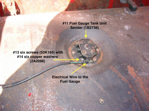
Fuel Gauge Tank Unit Sender

Fuel Gauge Tank Unit Sender Removed
Battery Cable Lead
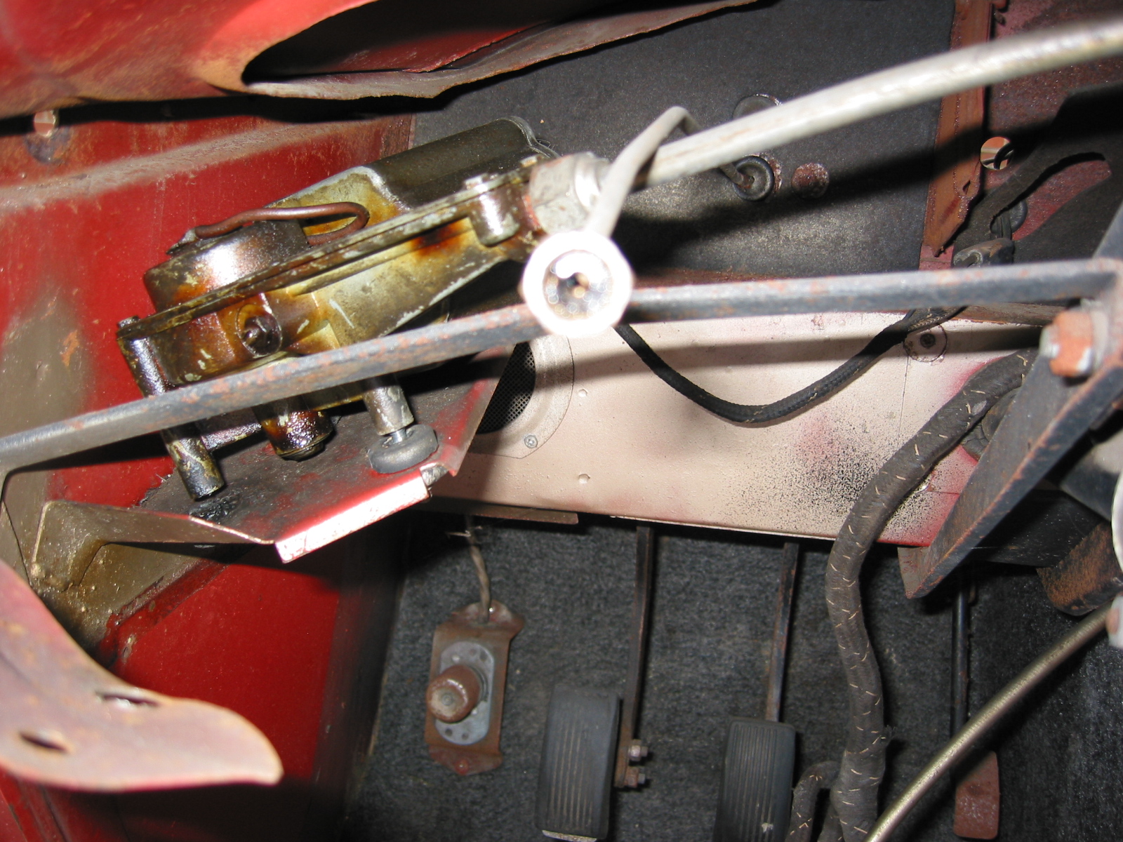
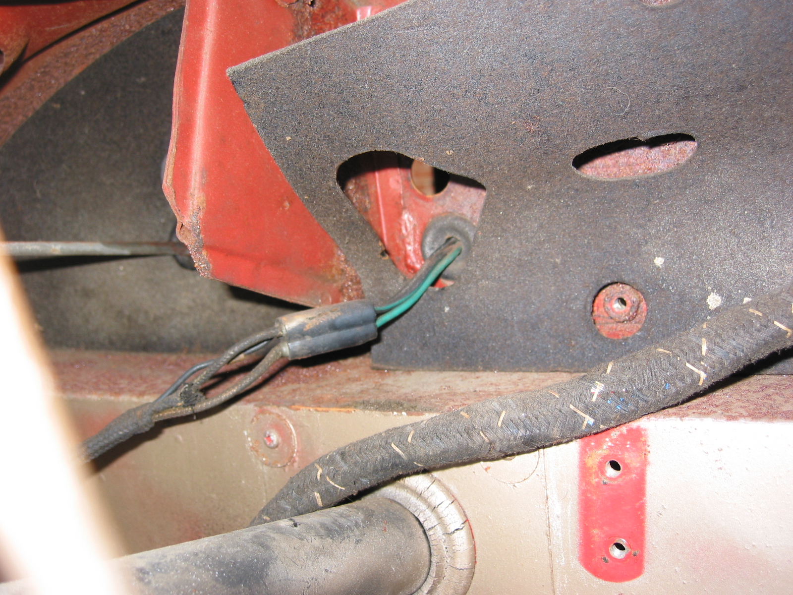
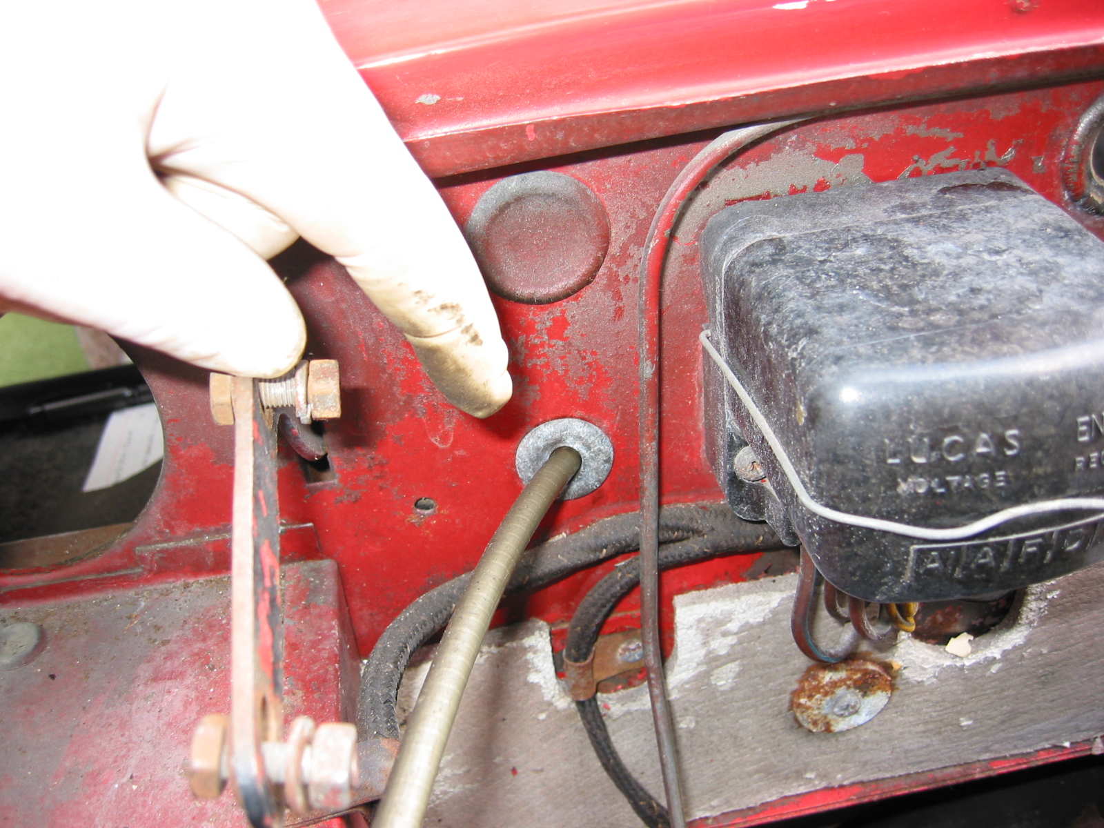
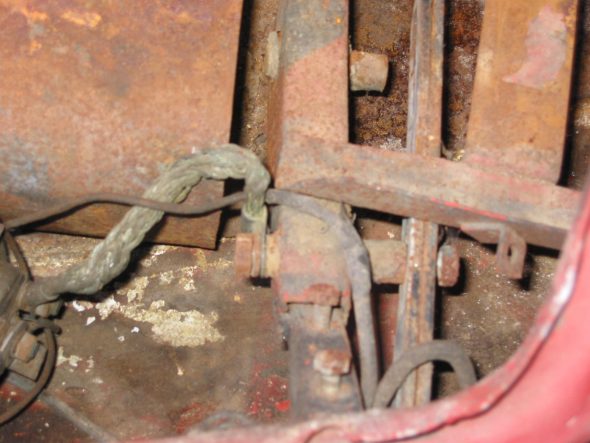
Loosened the battery cable at the battery post. I cut the cable at the terminal because I knew that I would be replacing the cable, but the proper routing involves removing the cable lead at the solenoid and then pulling rearward through frame clamps to the boot. Two rubber grommets were located in the filler tube wall and the rear kick panel.
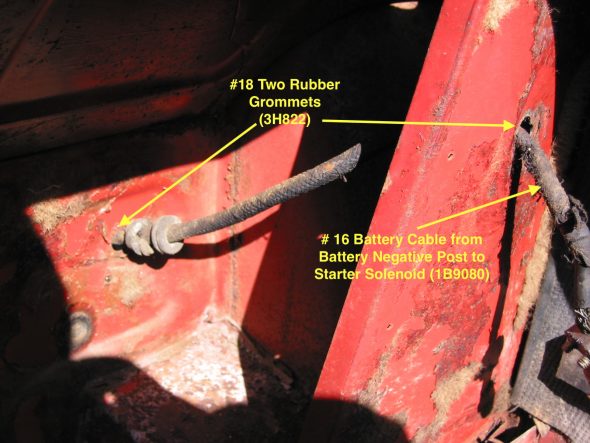
Battery Cable and Rubber Grommets in Boot
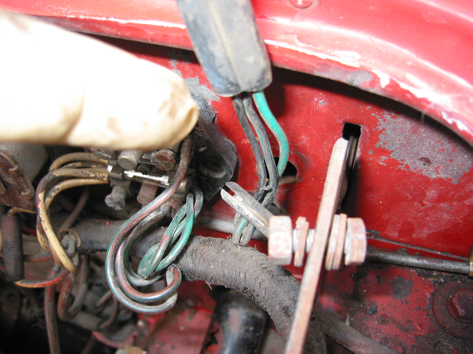
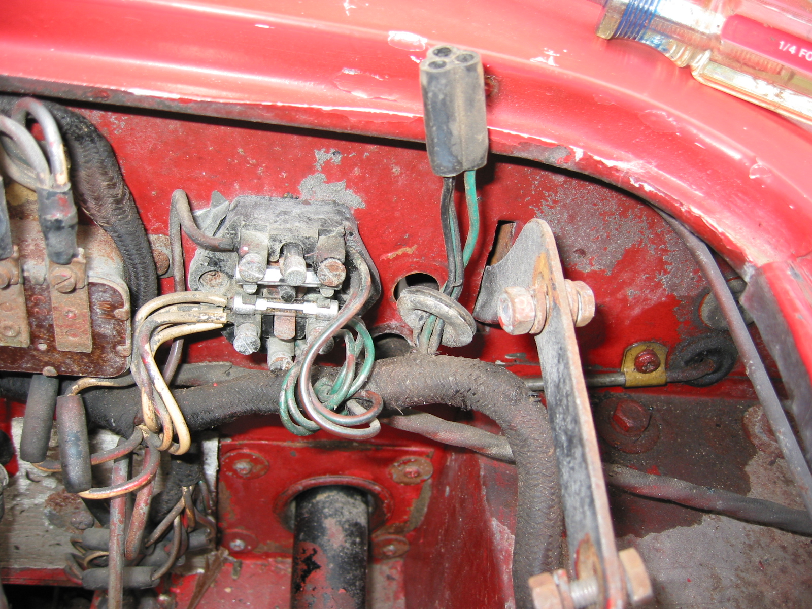
Battery Master Switch
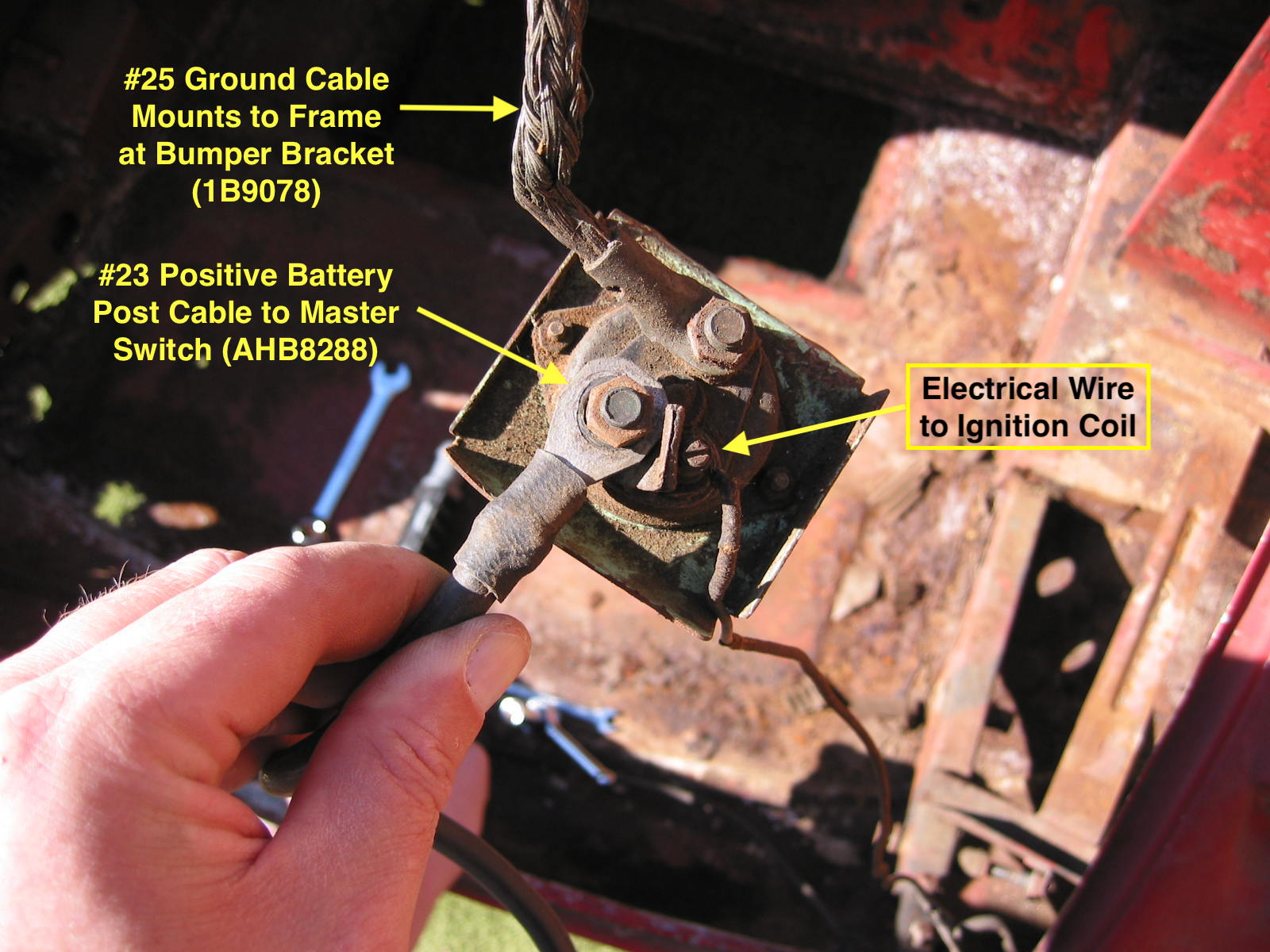
Removed two mounting bolts and disconnected the ignition wiring and ground cable to battery as well as the ground cable to the frame. It is reported that this switch was under-engineered and often the source of electrical problems so I will plan to replace it with an upgraded, but non-original, switch upon reassembly.
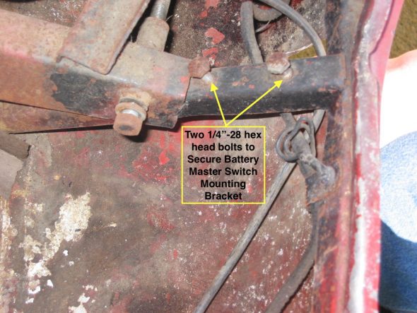
Battery Master Switch Mount
There are three electrical connections to the master switch. The earth or ground cable (1B9078) that attaches to the frame near the switch, the positive battery cable connecting to the + battery post, and the small wire to the ignition coil.
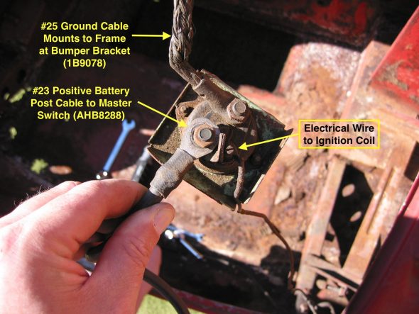
Battery Master Switch
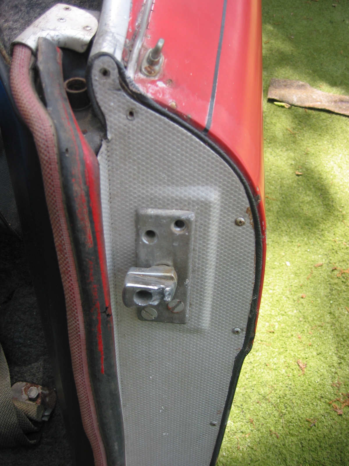
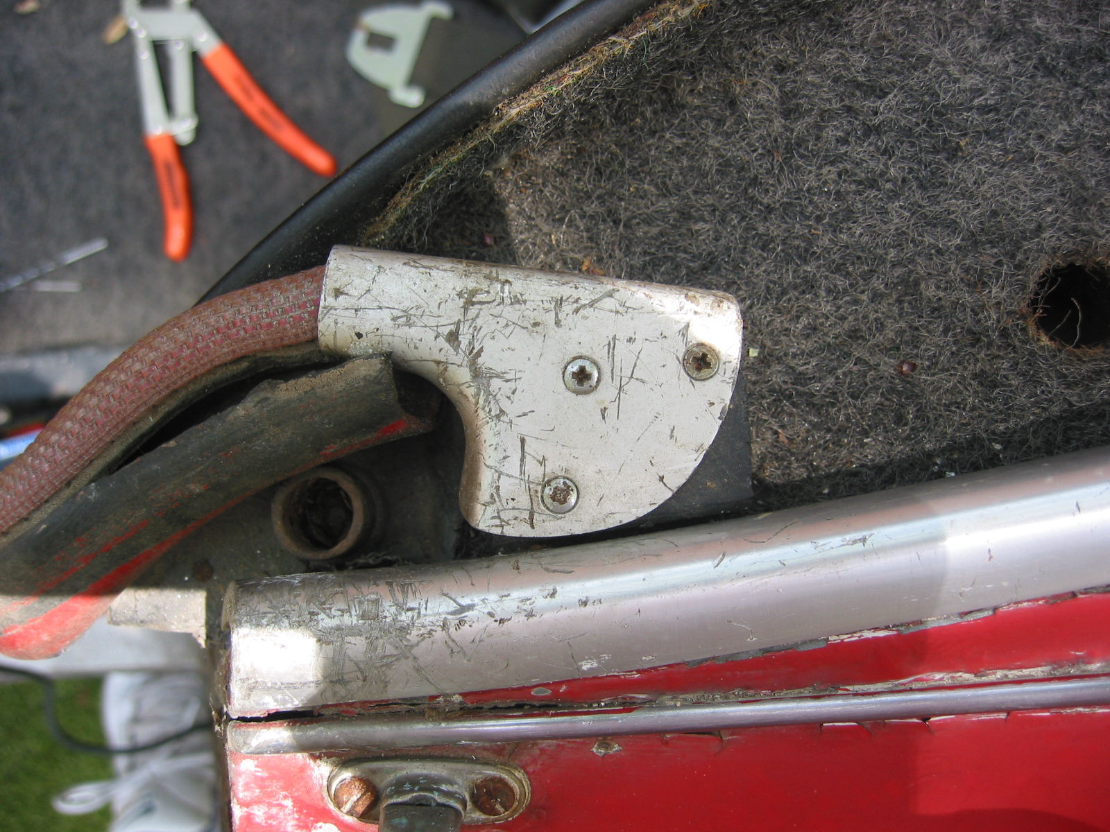
Boot Lid Striker
Removed the striker (14B1719), its packing plate (14B2809), a packing piece (14B6817) and the striker tapped plate (14B2038) from the boot frame by loosening three 1/4” bolts (HZS0407) with flat and split washers. This striker is adjustable to obtain the best fit with the boot lid lock.

Boot Lid Striker
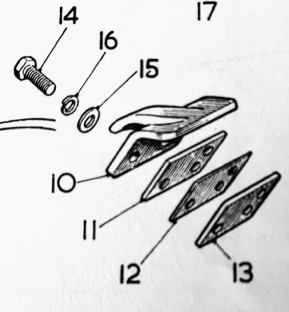
Boot Lid Striker Assembly
March 16, 2002
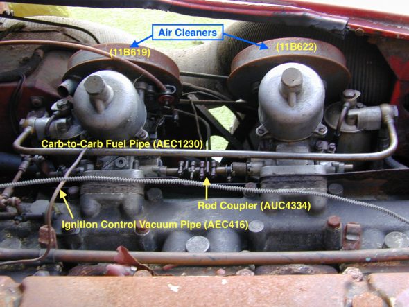
Carburetors
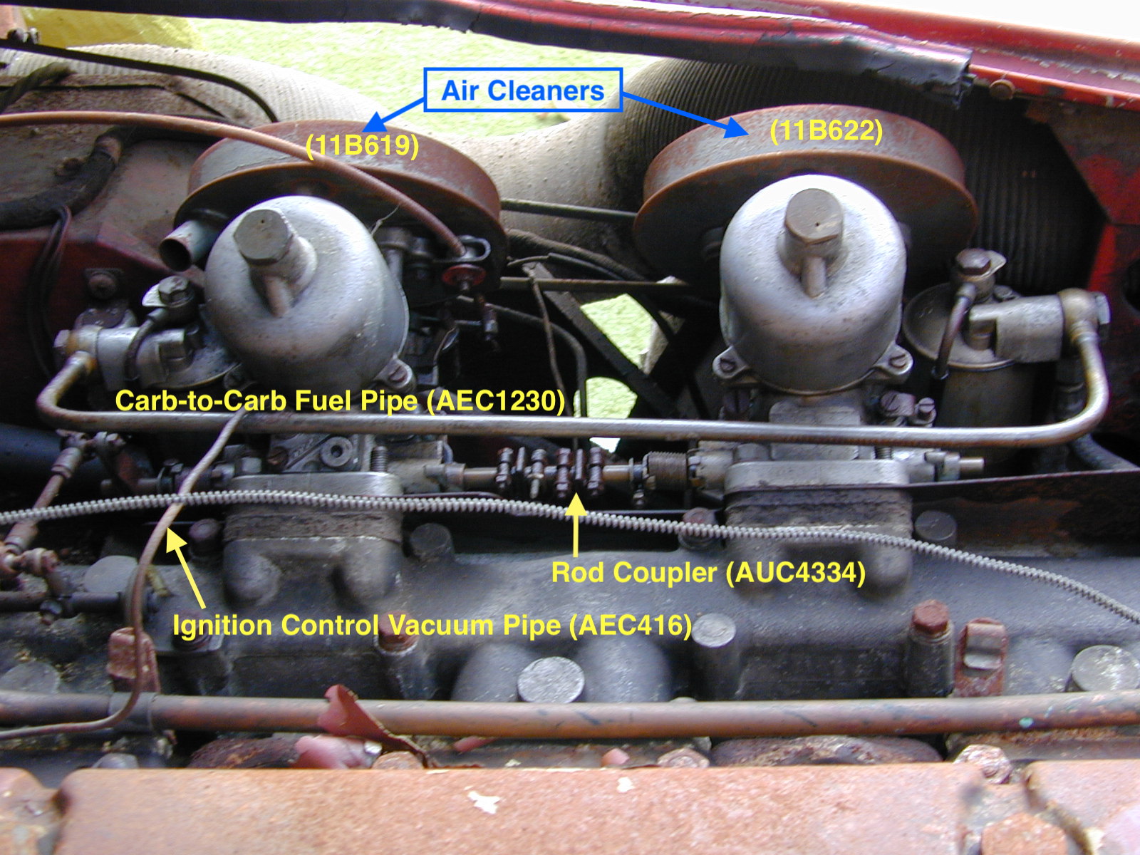
First step in the removal of the twin HD6 SU carburetors is the removal of the front (11B622) and rear (11B619) air cleaners. The rear air cleaner has a tube for the breather hose from the rocker cover. The screws on the clips (AEC442) for each end of the hose (1G2268) must be loosened so as to remove the breather hose. Each air cleaner is mounted to its carb with two hex head bolts (HZS0506), flat and split washers. These could then be set aside.
Next was the removal of the carb to carb fuel pipe (AEC1230). One fibre washer (AUC4121) on each side of the brass banjo bolt (AUC2698). Filter cups (AUC2139) with springs and washers fit into the float chamber lids at this junction. The pipe could then be removed and set side. The banjo bolts, washers and filters were refitted to the float chamber lids.
Carb Removal
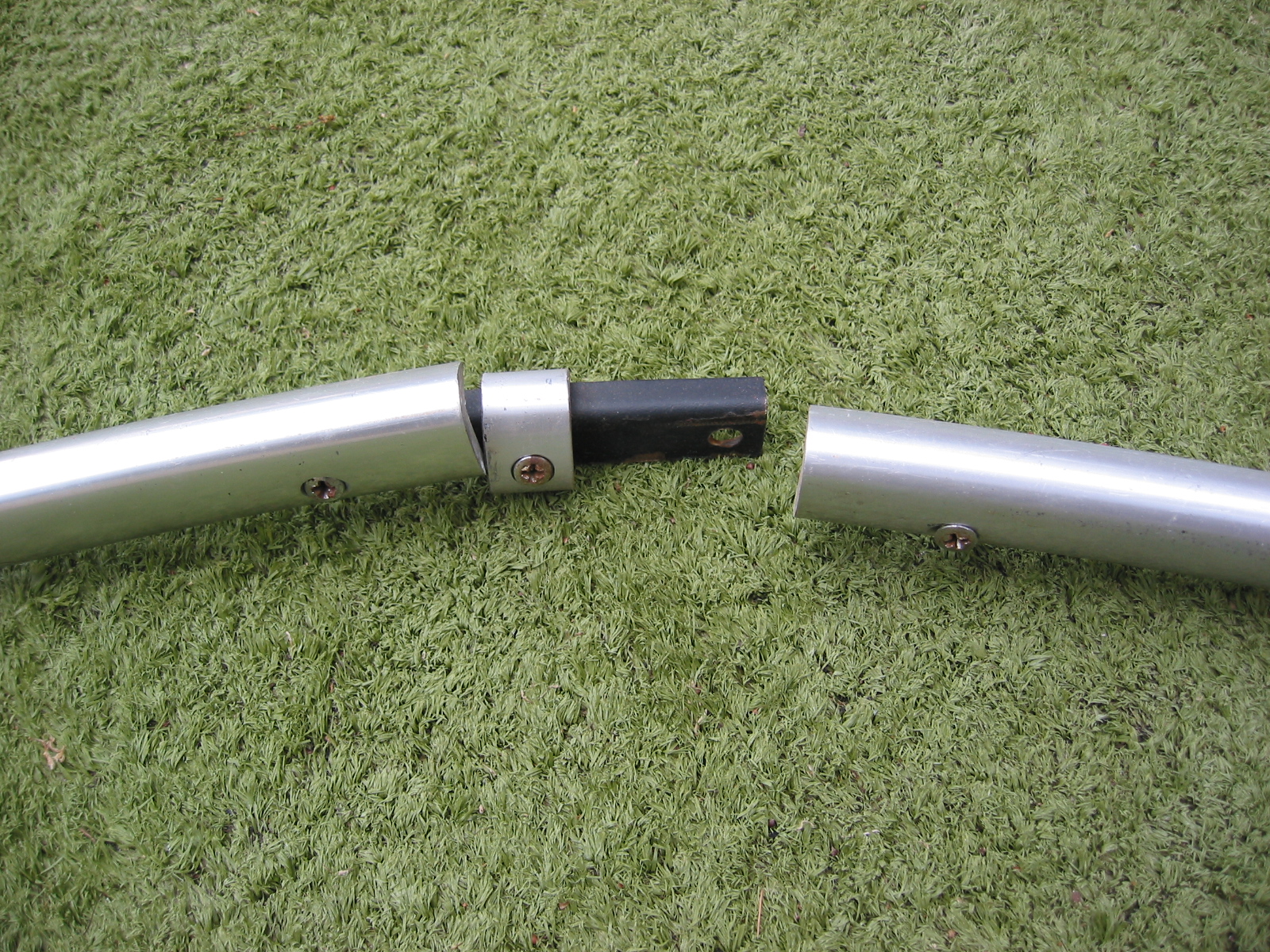
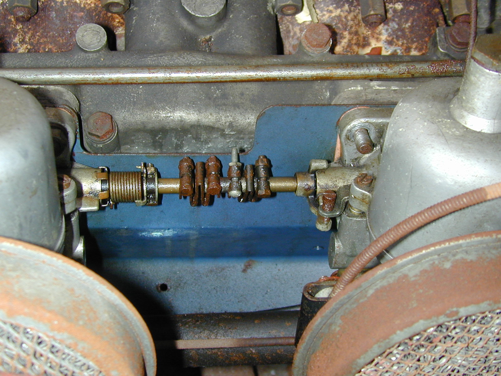
Loosened the nuts on each of two screws on one of the ribbon rod couplers (AUC4334) so that the carbs could be separated.

Carb Throttle Shaft Connector
This also required freeing the choke jet lever connecting rod (AUC2867) at the bottom of the carbs. First removed the cotter pin from the pivot pin (AUC2108) that held the connecting rod end fork (AUC2256) on the front carb.
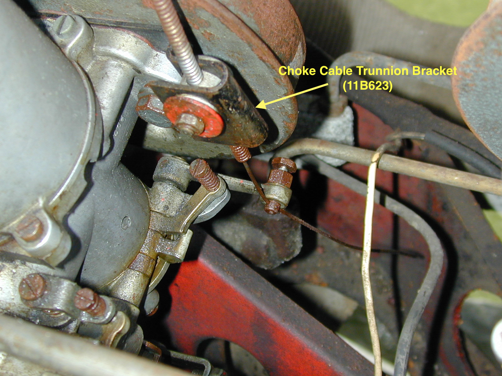
The choke cable must also be loosened and removed. The cable is routed through the choke cable trunnion in the bracket (11B623) on the rear carb, fitting between the carb and the air cleaner. A gasket (AEC375) is located on either side of the bracket. The front carb has only the one gasket between the air cleaner and the carb.

Choke Bracket on Rear Carb
Each carb is mounted to the intake manifold studs with four 5/16″-24 (FNZ105) nuts, flat and split washers. A couple of the nuts on the underside of the carbs are not easy to access!
The ignition control vacuum pipe (AEC416) from the distributor must be disconnected from the rear carb by loosening its fitting nut (2K6193). The assembled carb unit may be then removed from the manifold. A nylon overflow pipe (AEC981 and AEC982) for each carb float bowl lid can be lifted away with the carbs.
A gasket (AED308) is found between each carb and the Heat Shield (AEC1357). These are removed and then the heat shield can be lifted away from the manifold. Between the heat shield and the manifold there is an insulating distance piece (AEC368). These were also removed.