Power Inputs to the Classic Technologies’ Relay/Fuse Panel
The Classic Technologies Panel has four primary connections.

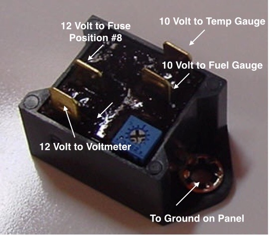
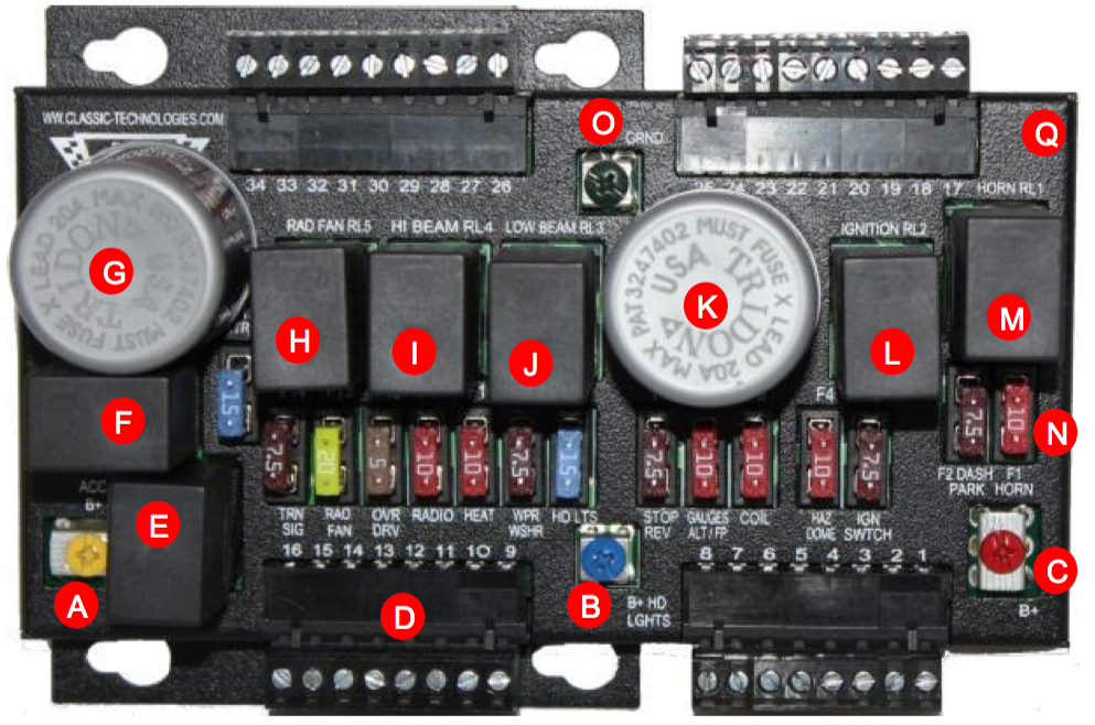
Classic Technologies’ Relay Fuse Panel
A – 12V power input from the small fuse box (battery B+) to power the accessories circuits. A brown 12 AWG wire is used to the Yellow screw terminal spade lug connection.
B – 12V power input from the small fuse box (battery B+) to power the high and low beam headlight relays. A brown/blue 14 AWG wire is used to the Blue screw terminal spade lug connection.
C – 12V power input from the small fuse box (battery B+) to power the constant power circuits in the vehicle. A brown 12 AWG wire is used to the Red screw terminal for a spade lug termination.
O – ground or earth to the car’s chassis.
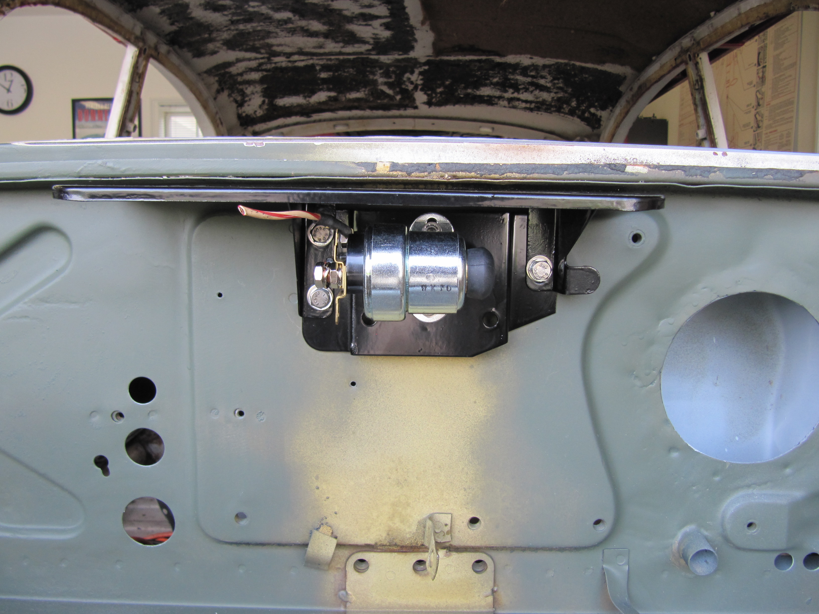
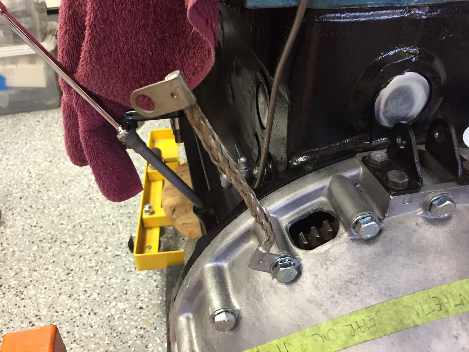
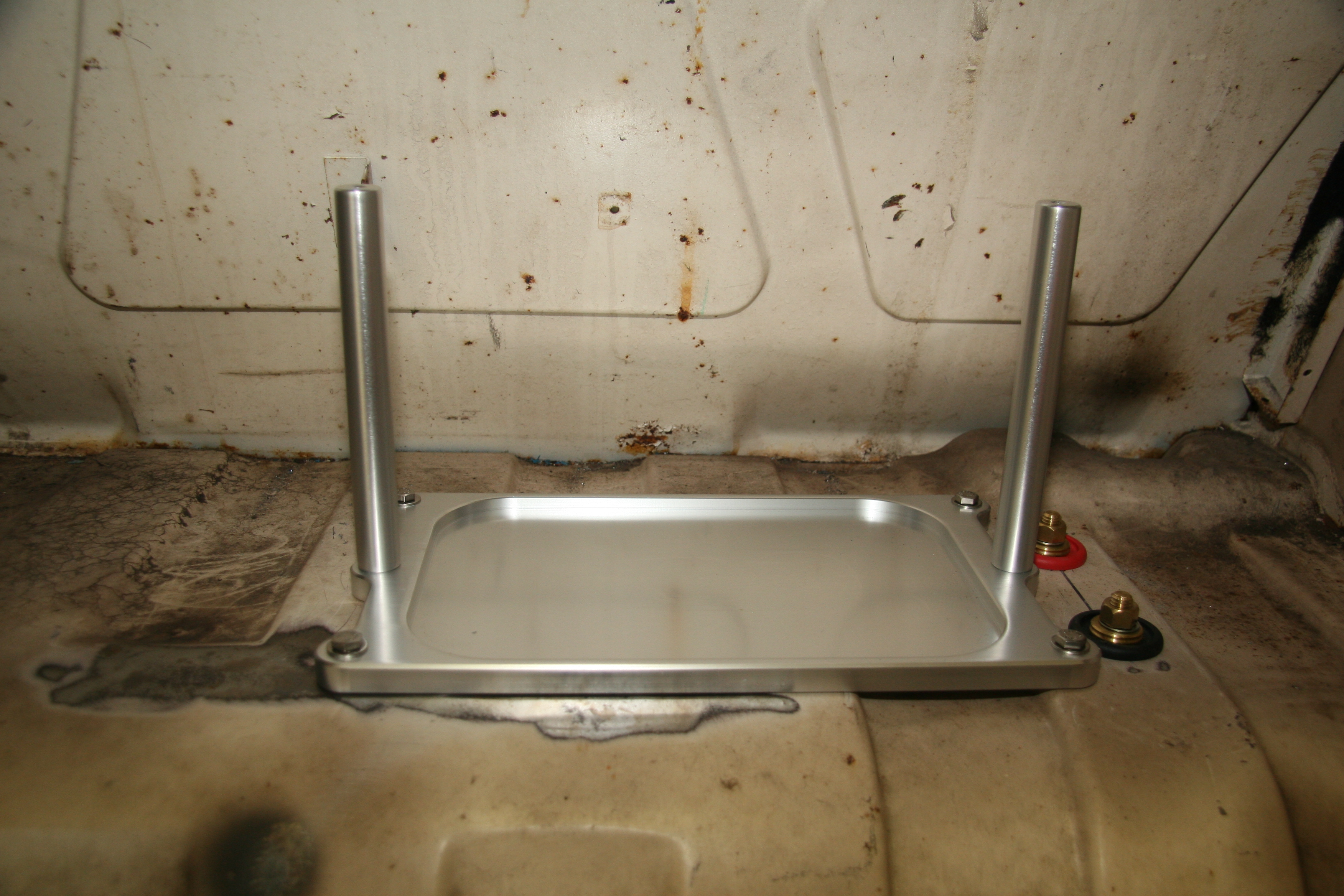
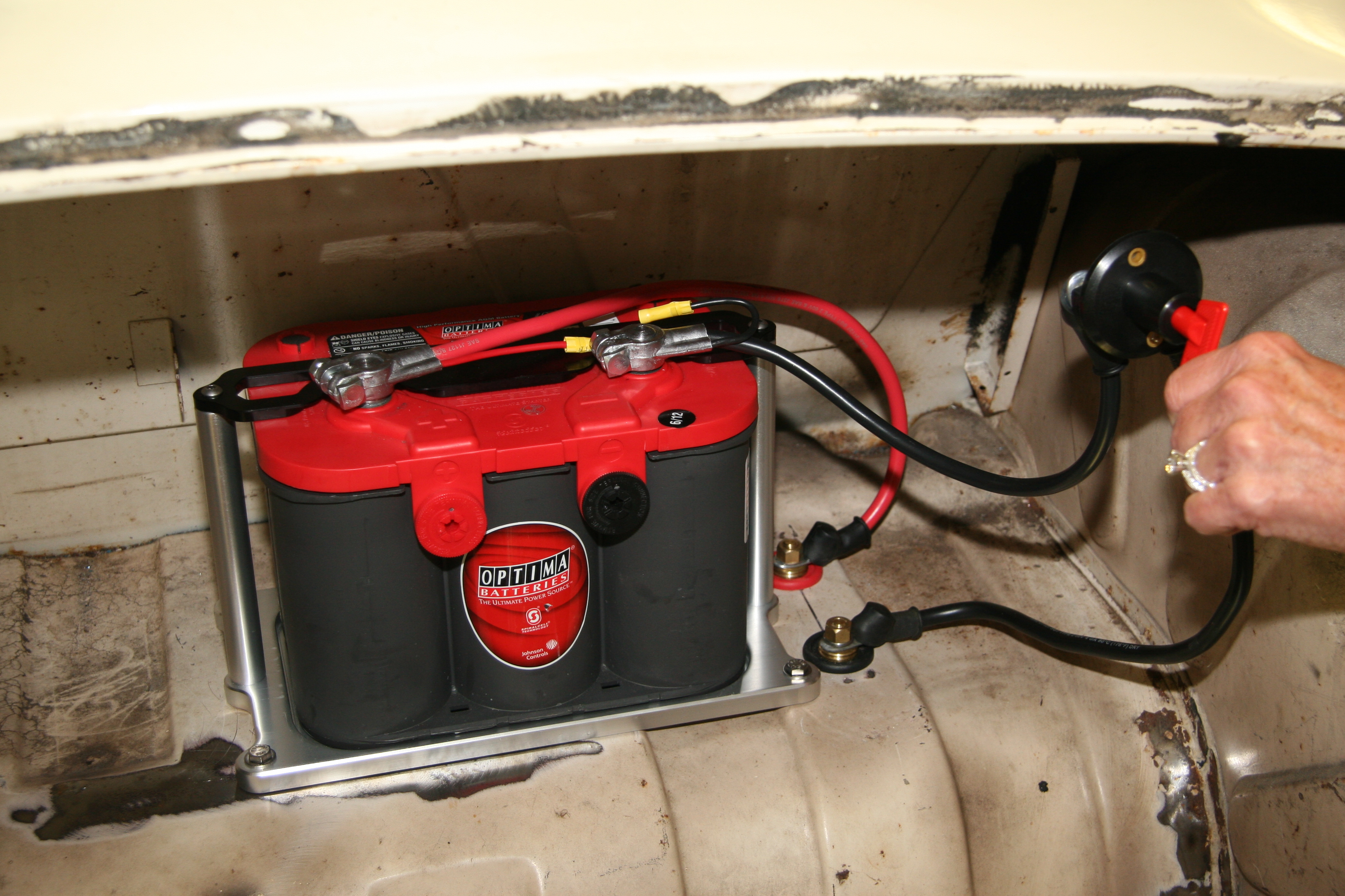
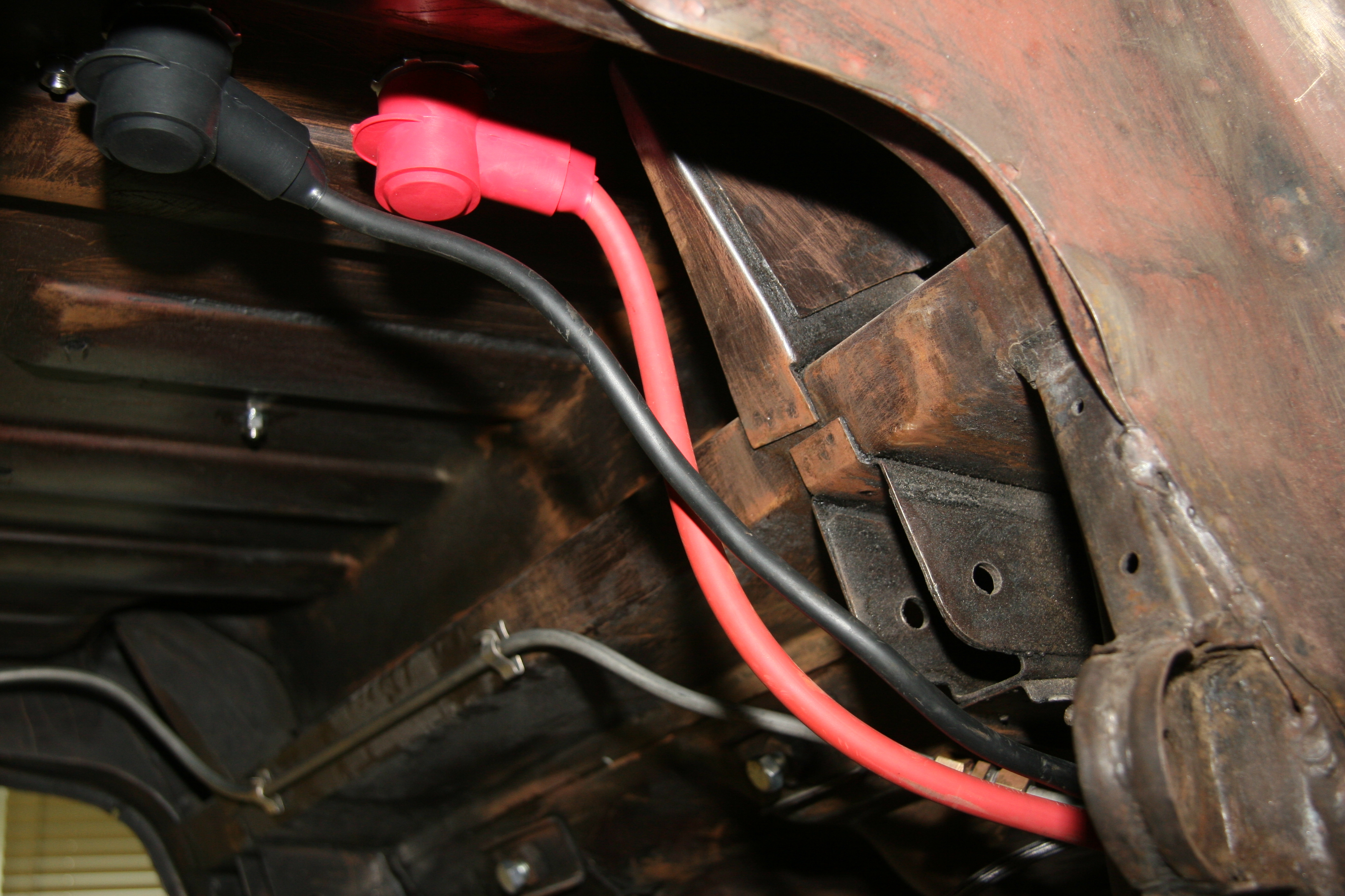
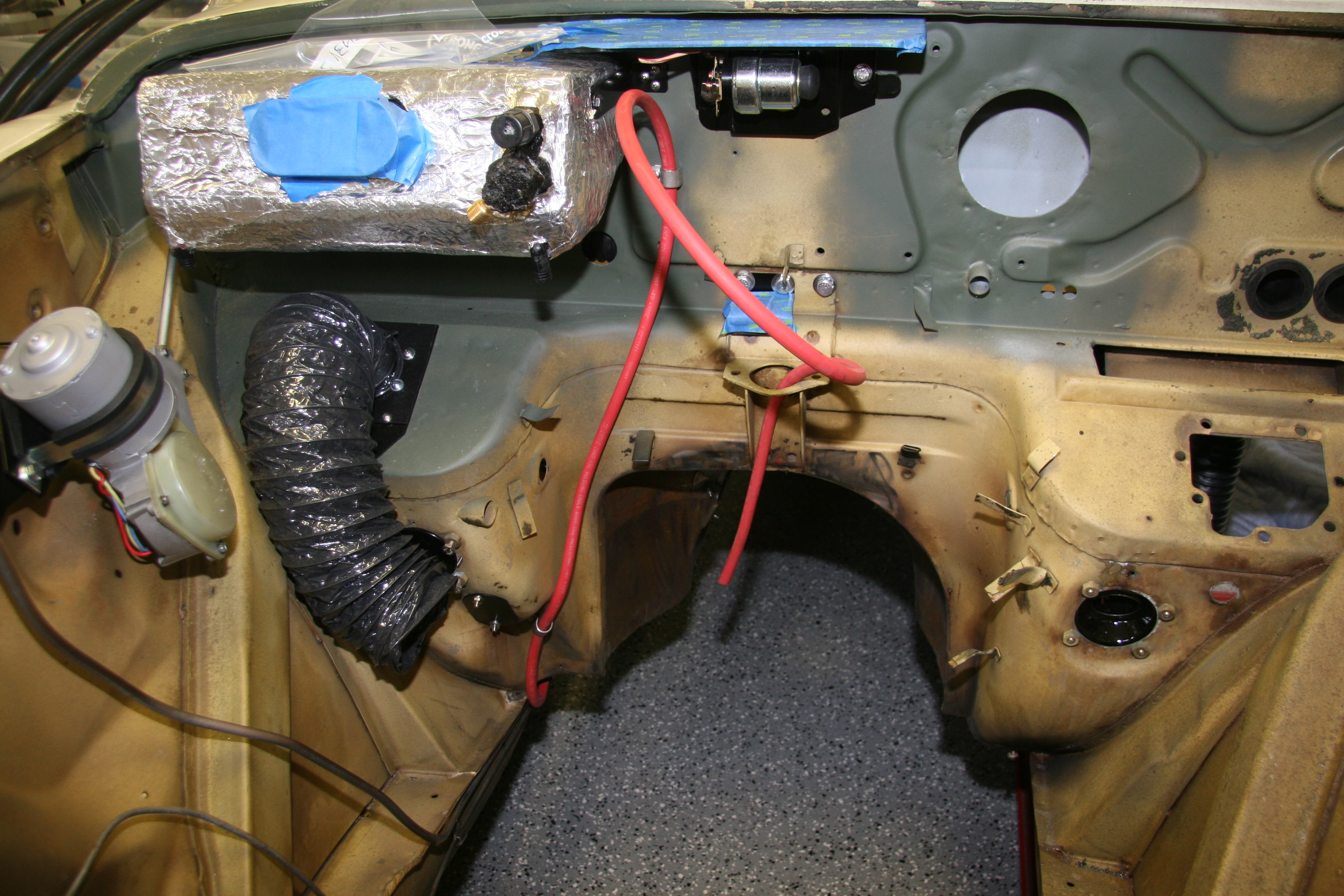
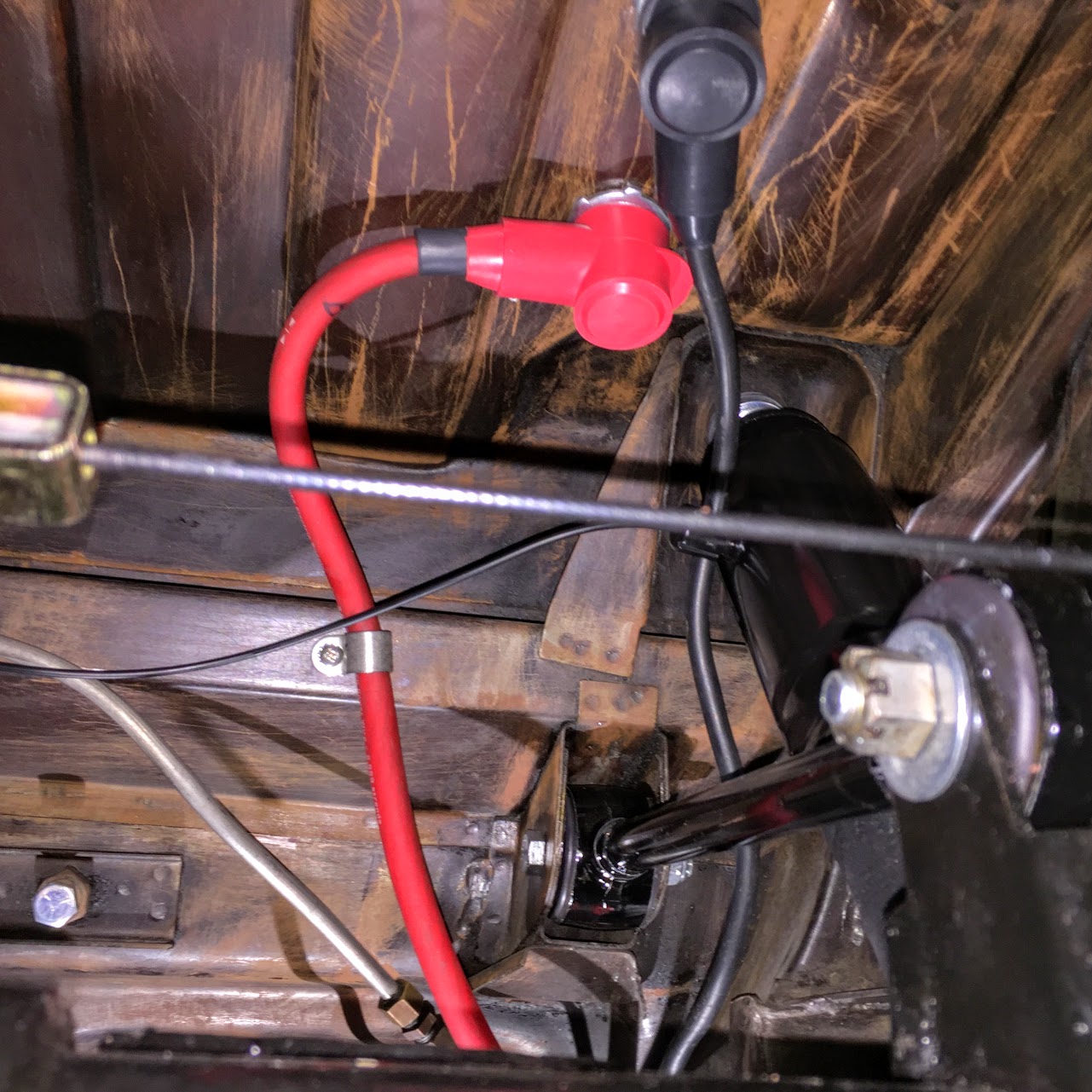
In my case, 12V power is routed from the battery in the trunk to the starter solenoid mounted centrally on the firewall in the engine bay. The negative terminal of the battery is wired to the car’s chassis. A ground strap is used to connect the grounded chassis to the engine/gearbox.

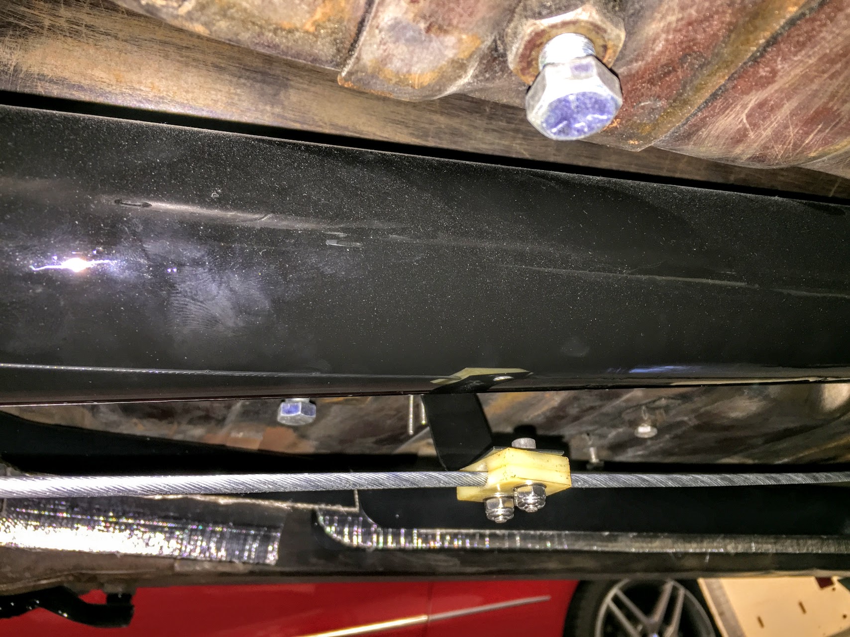
Ground Strap Mounted
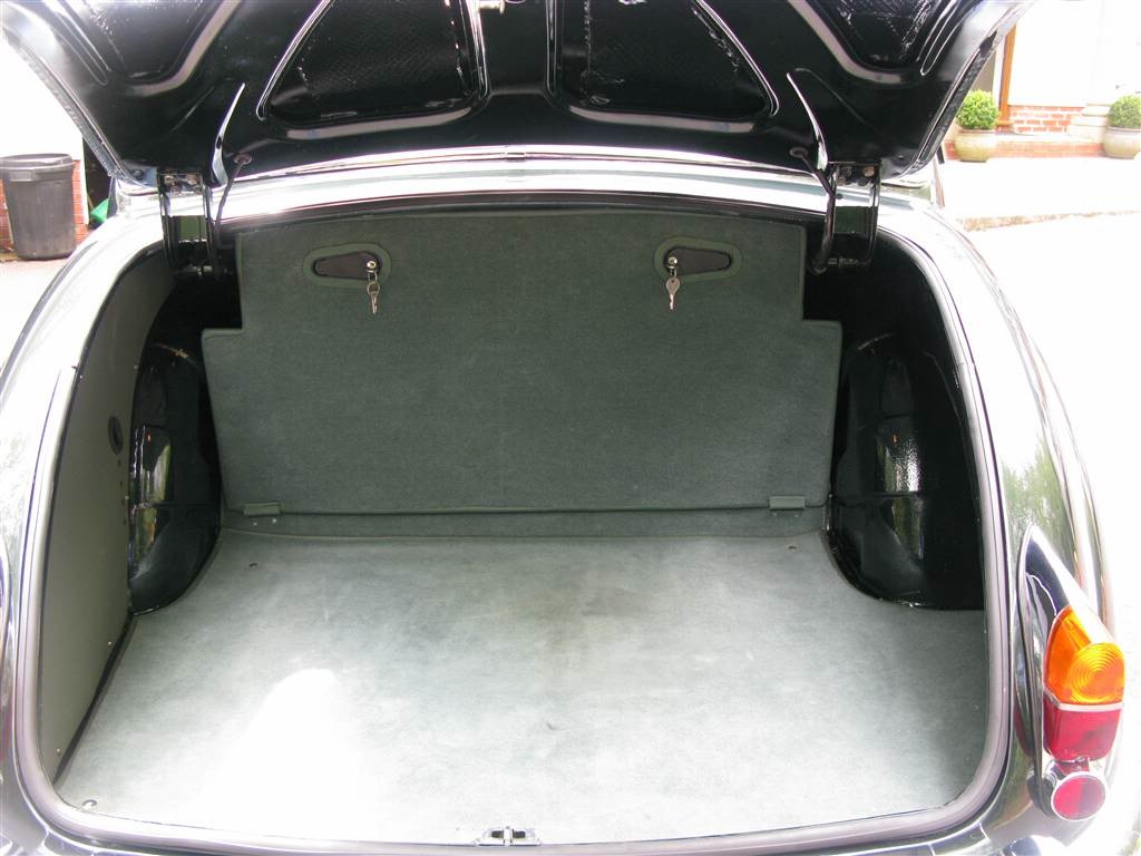
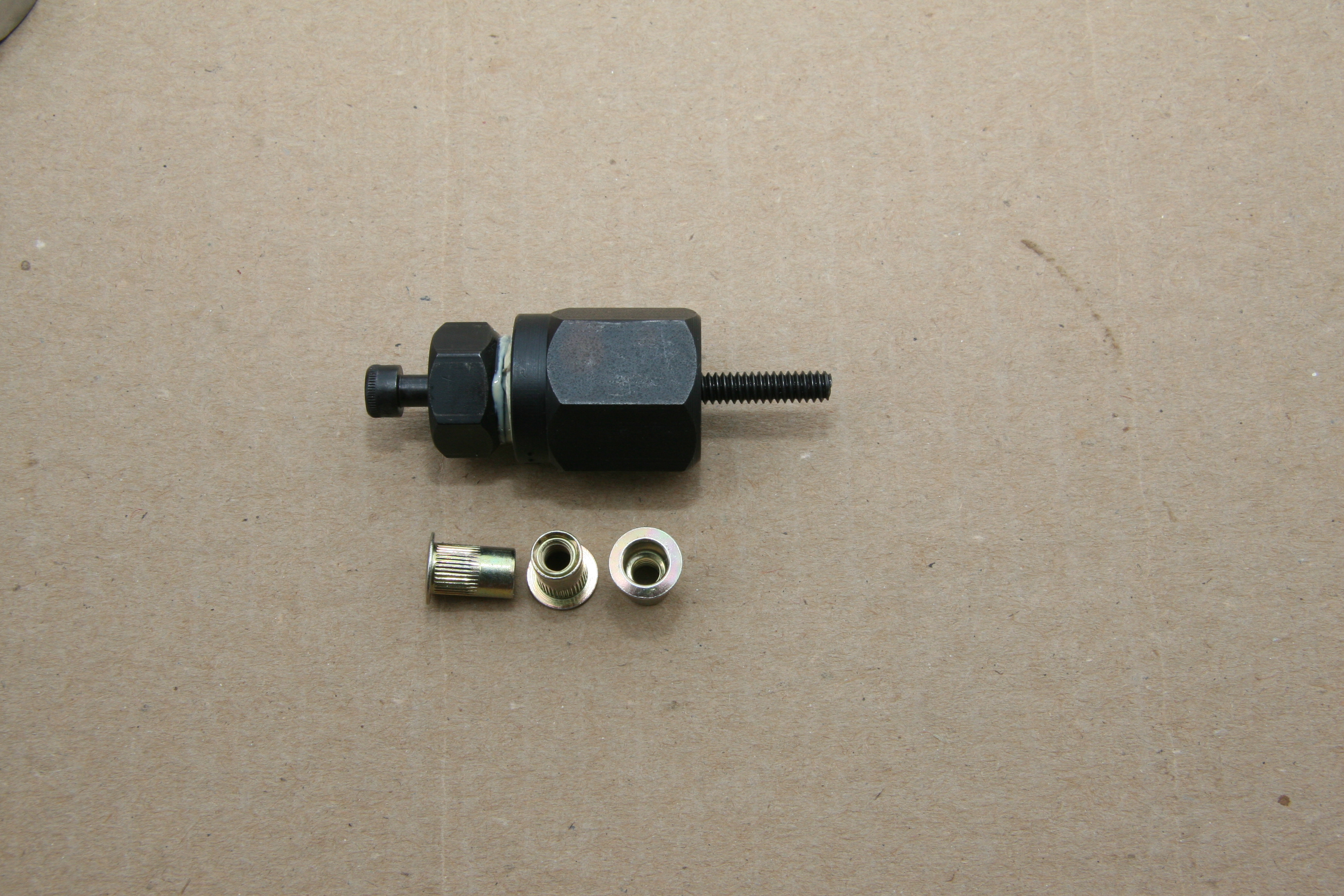
The battery relocation to the boot was addressed in a previous post.From the solenoid, a brown 8 AWG wire delivers power to a small fuse box with six circuits mounted on the firewall directly below the starter solenoid. I used two nutserts for the mounting to the firewall. Three of the six fused circuits are then used to provide power to three input terminals on the Classic Technologies’ relay/fuse panel. The additional three are spares for the moment.
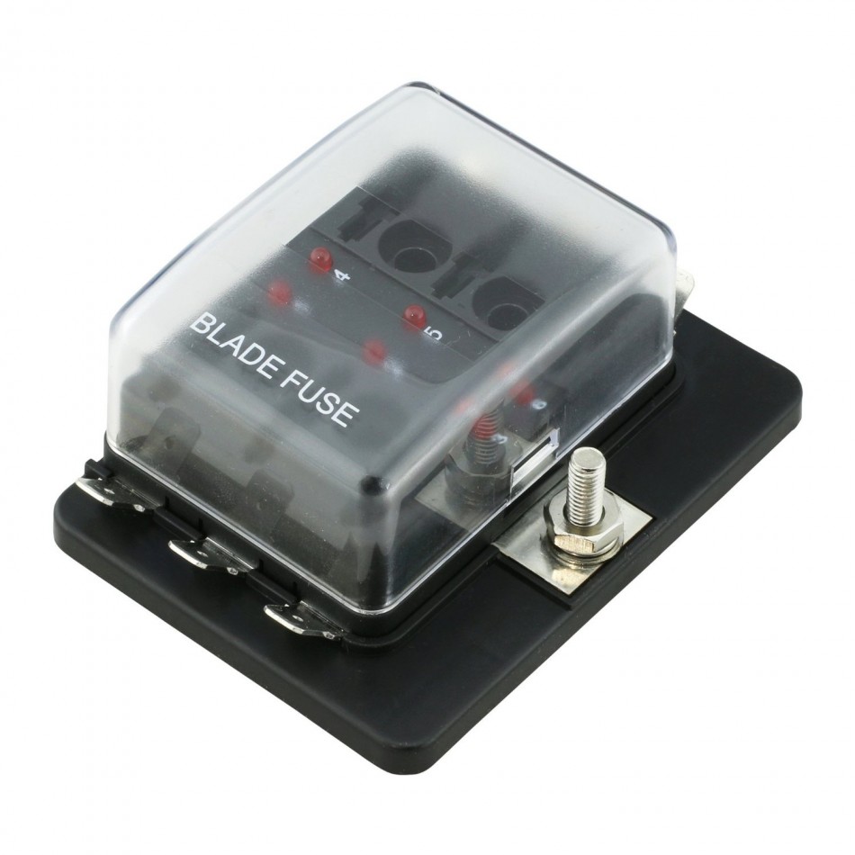
OnLine-LED-Store Six-Way Fuse Box
This is a diagram of the wiring to the Relay/Fuse Panel:
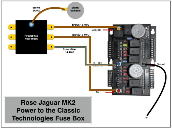
Rose Jaguar MK2 Power to the Classic Technologies Fuse Box
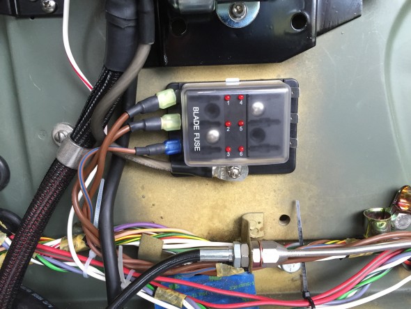
Six Way Firewall Fuse Box Delivering Power to Classic Tech Relay:Fuse Panel
The three wires from the small firewall fuse box, the white/red wire from the solenoid to the fuse panel and the heavy 4 AWG cable from the solenoid to the alternator will be “packaged” together in one TechFlex sleeve/cover.
Before getting into the allocation of the thirty-four fuse positions available to use in the Classic Technologies Relay/Fuse panel, it might be helpful to once again point point out that as indicated in the post on new wiring harness connectors I developed a spreadsheet to be used in conjunction with wiring diagrams. The spreadsheet lists all connection points of the electrical wiring system. Links are provided below:
Again, a disclaimer is appropriate: The spreadsheet is provided as guidance for those who might wish to do something similar, but it should not be duplicated or utilized without careful inspection and approval by a certified automotive electrician.
This alphabetical listing of components is provided to help quickly identify items in the electrical system. A spreadsheet line number(s) associated with the component is indicated.
Rose Jaguar MK2 Electrical Connections Alpha listing
This is the spreadsheet showing all connections:
Rose Jaguar MK2 Electrical Connections Spreadsheet
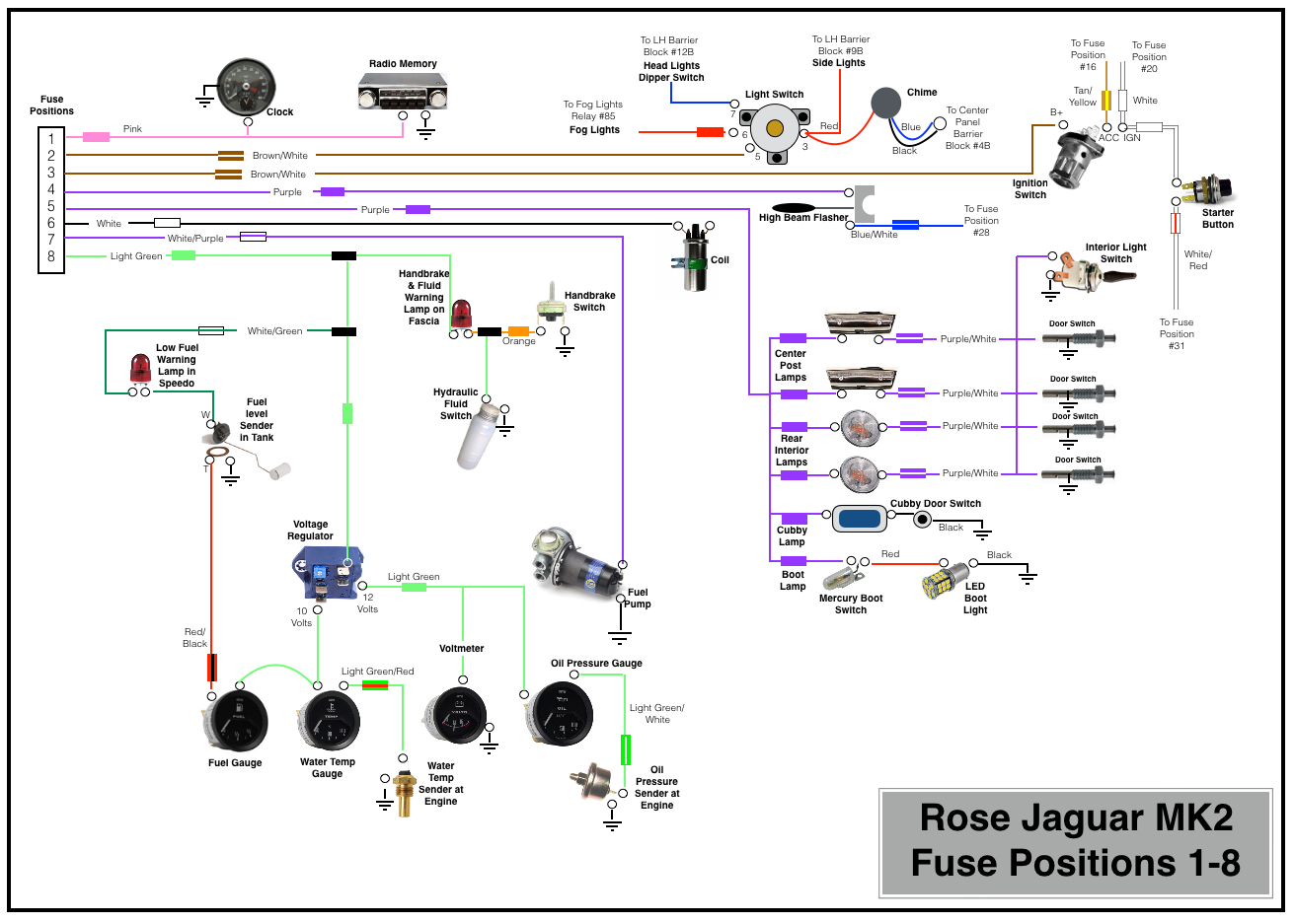
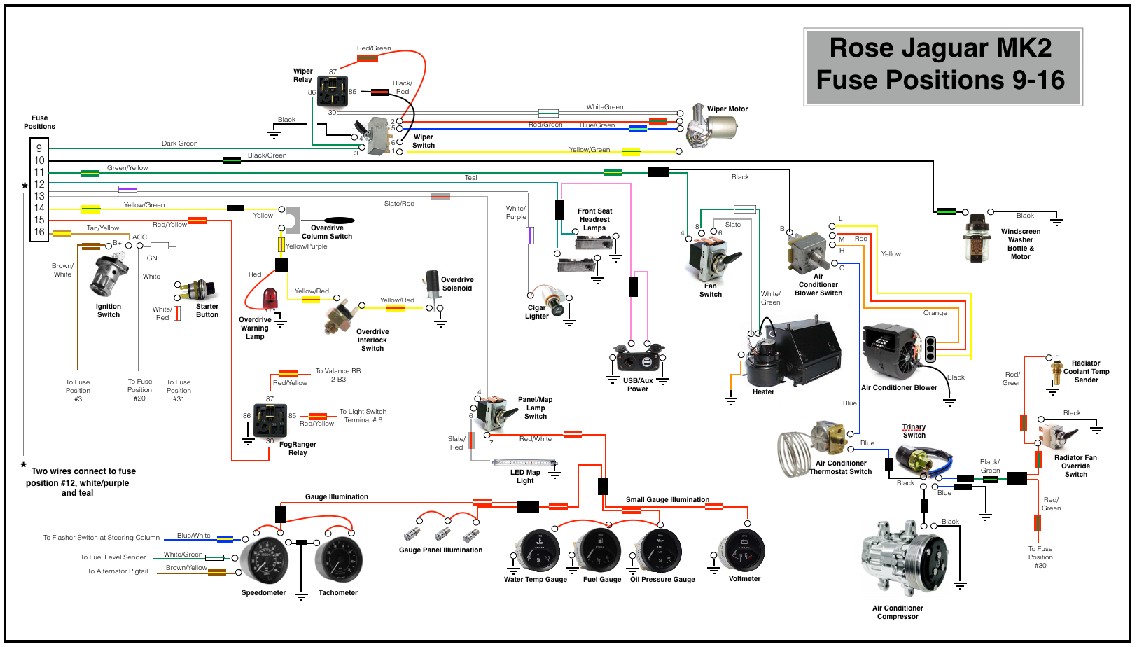
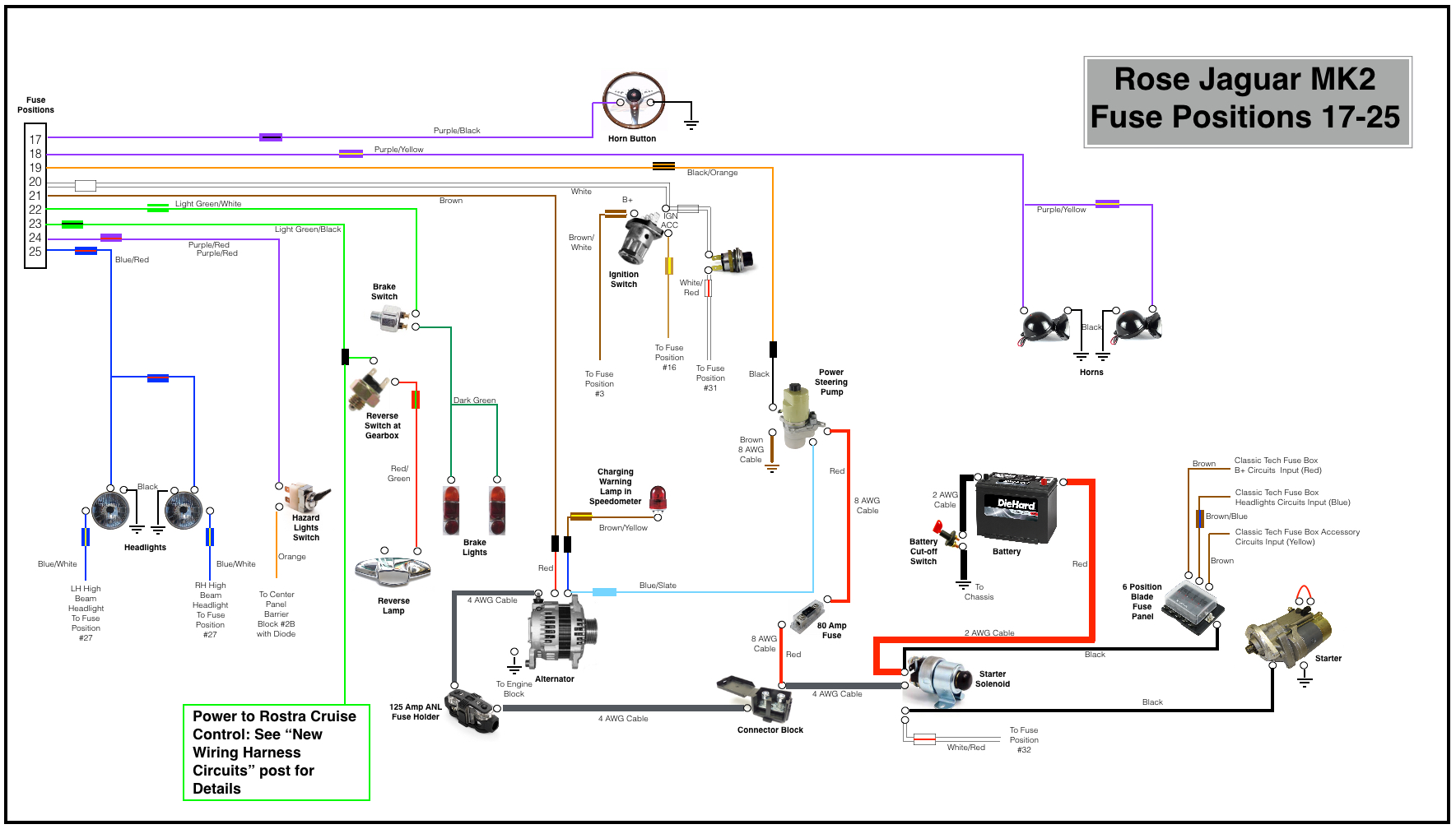
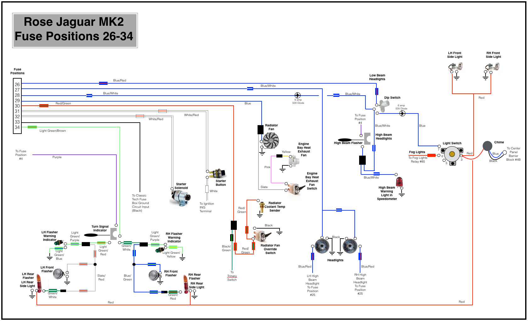
The following four diagrams illustrate the wiring sourced from the thirty-four fused positions in the system. Please let me know if as a reader you note an error or an omission. I apologize for the somewhat primitive diagrams as I did not have proper software available to do the job. I resorted to “Keynote” a presentation software to complete the task.
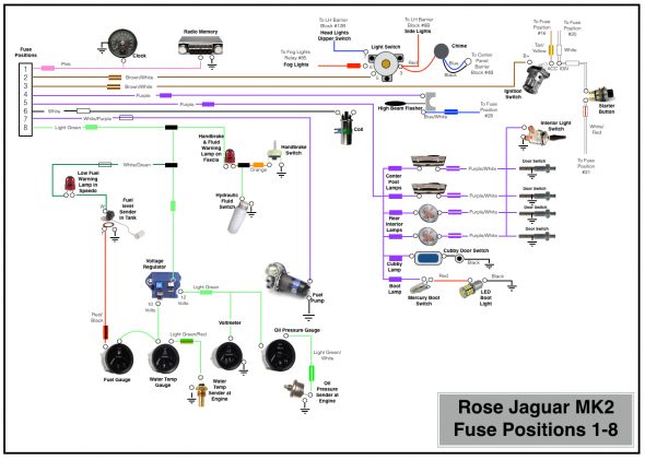
Rose Jaguar MK2 Fuse Positions 1-8

Rose Jaguar MK2 Fuse Positions 9-16
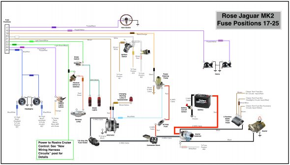
Rose Jaguar MK2 Fuse Positions 17-25

Rose Jaguar MK2 Fuse Positions 26-34
Circuit Modifications & Additions
Several of the modifications I am making to my MK2 require either modified or new electrical circuits. I highlight below the details of some of these wiring changes.
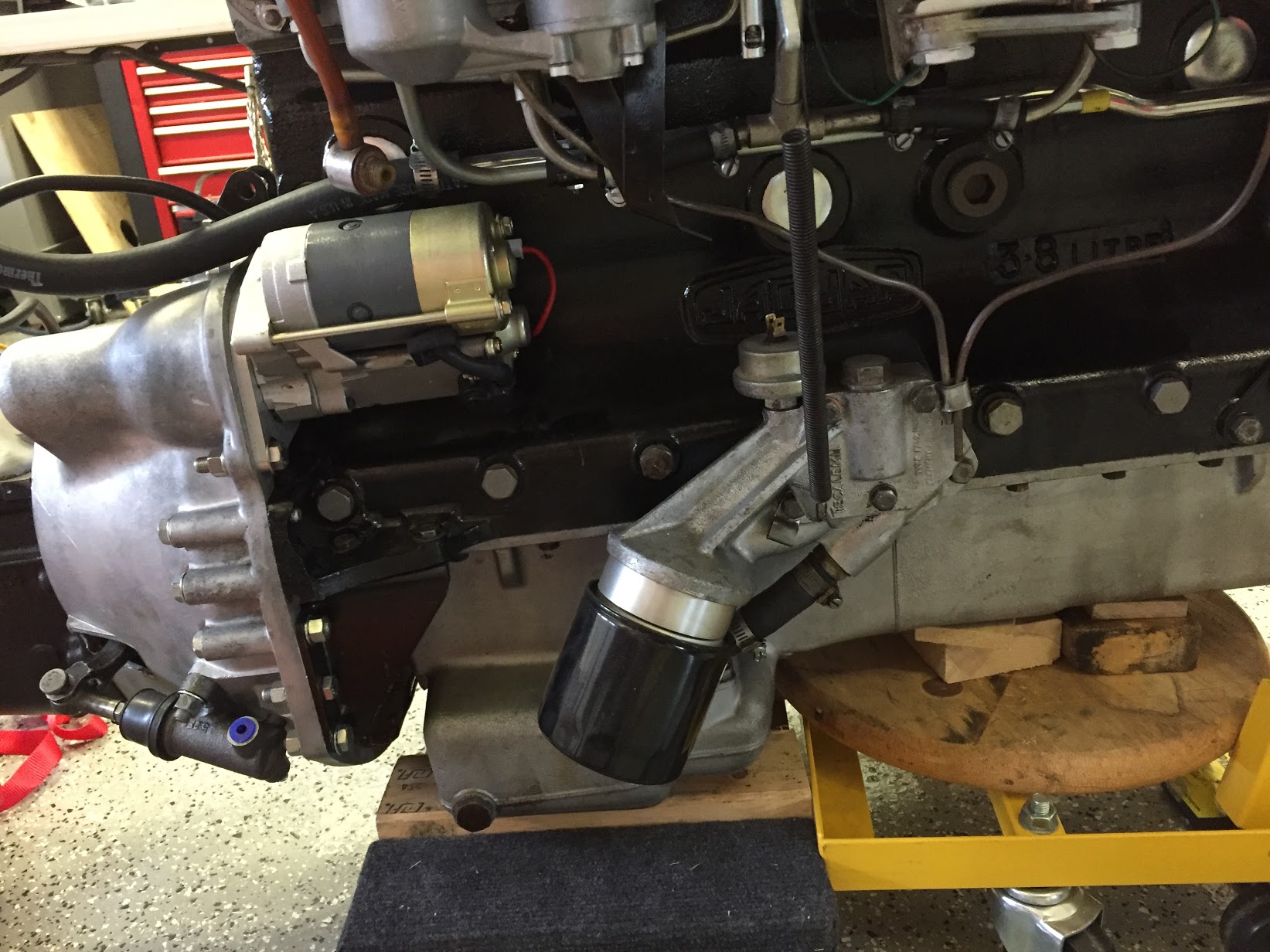
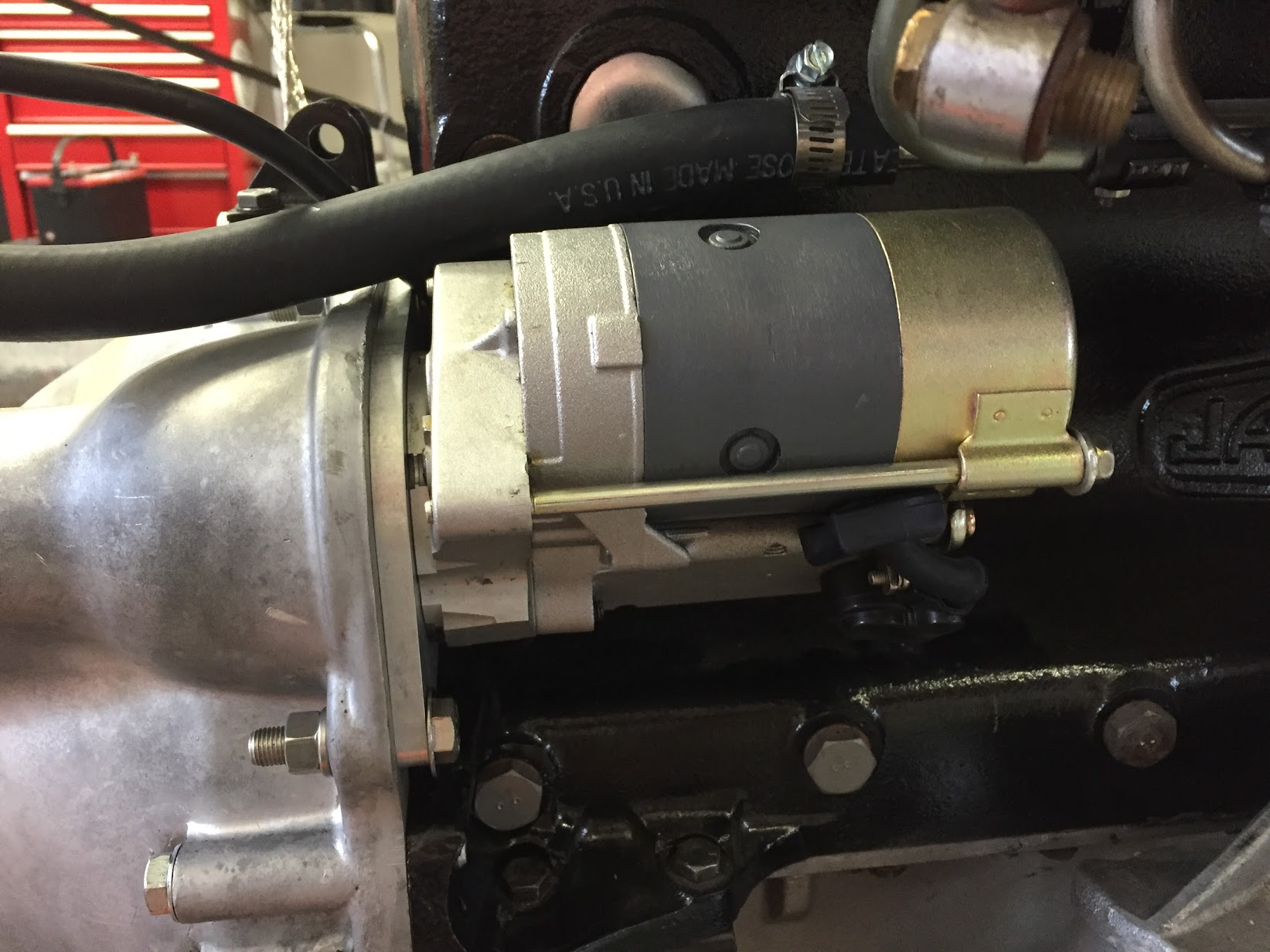
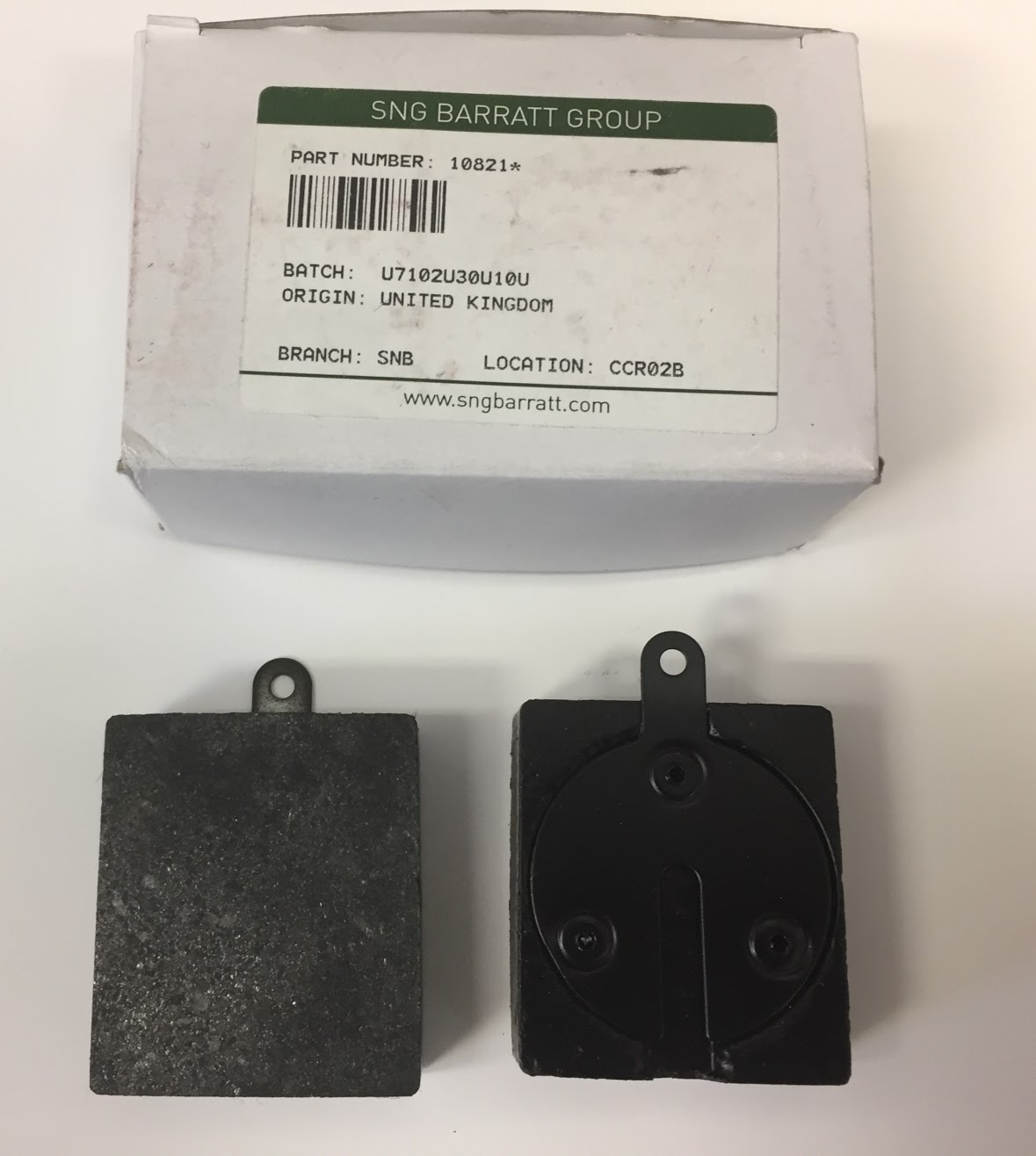
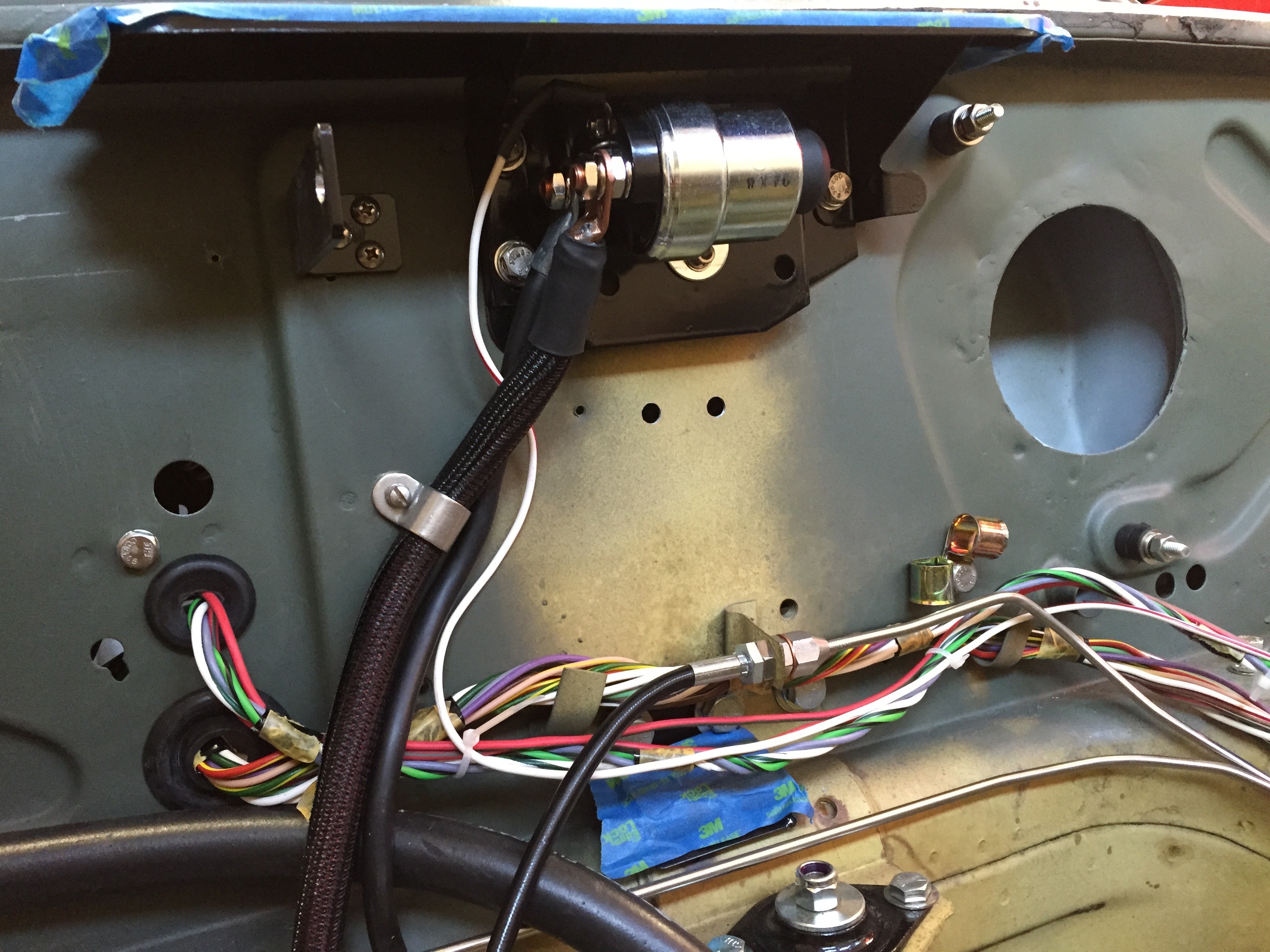
Starter Solenoid
I replaced the original starter solenoid with a new one sourced from SNG Barratt. The large post closest to the firewall provides the mounting for the 4 AWG cable to the starter. The large post closest to the engine mounts three cables: the 2AWG cable from the battery, the 4AWG cable to the block connector on the electrical panel on the LH engine bay valance (ultimately to the alternator), and a 8AWG wire to the 6-way firewall fuse panel. On the upper small post on the solenoid a single wire from the starter button is attached.
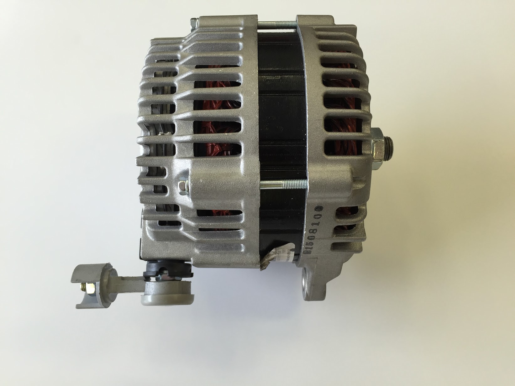
Alternator
I have considerably more power requirements in my car than could be addressed by the original dynamo/generator.
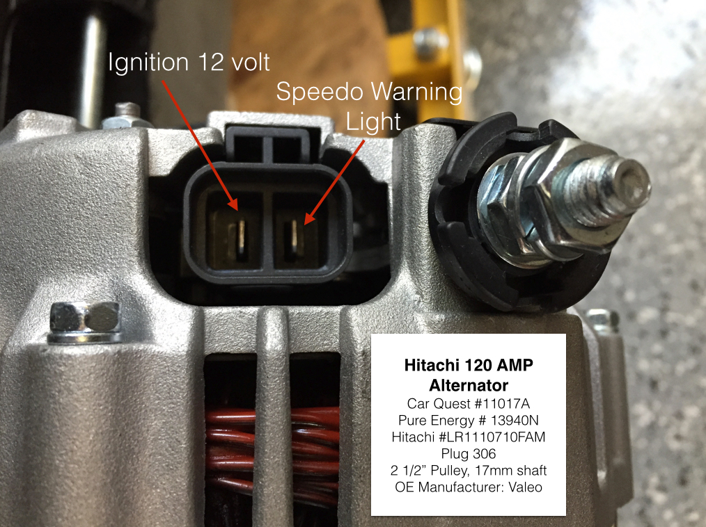
The specifics of the Hitachi 120 amp alternator I am using may be found under the “electrical components” posting. However, I will detail the wiring to support the alternator here.
I decided to go with 4AWG cable and also decided to install a fuse in the line between the alternator and the wiring system to avoid any possibility of a problem with a power surge created by a bad regulator in the alternator.
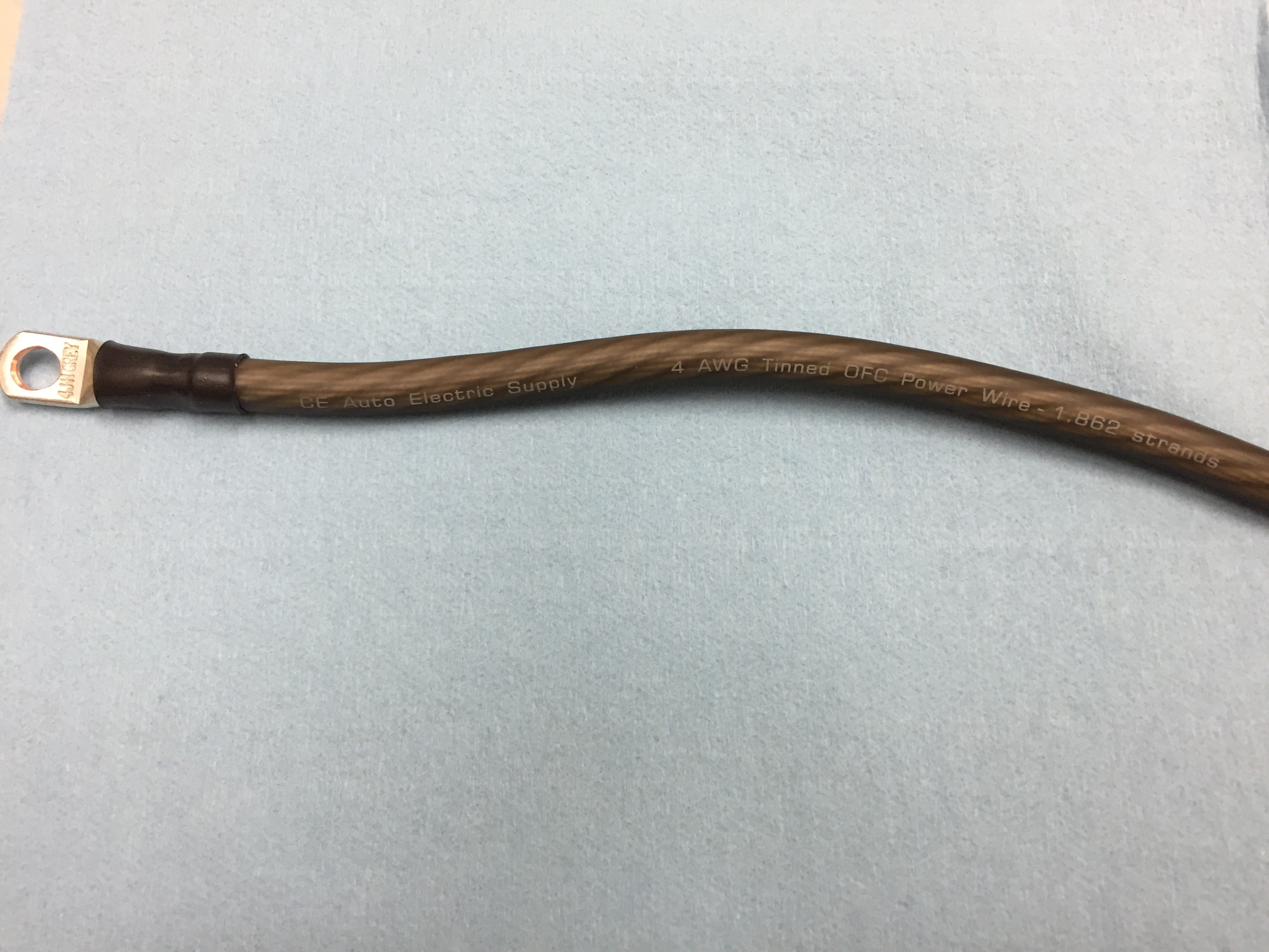
I sourced the cable and fuse from CE Auto Electric Supply. The folks at CE Auto Electric Supply are very helpful and they sell high quality products. Both products are typically used in high-end sound system applications. This particular cable has 1,862 strands. The cable was terminated with 3/8″ terminals, properly crimped and covered with adhesive shrink tubing.
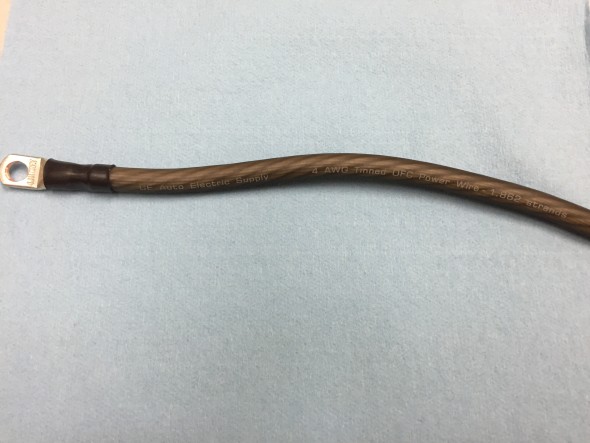
Alternator Cable CE Supply 4AWG 1862 Strands
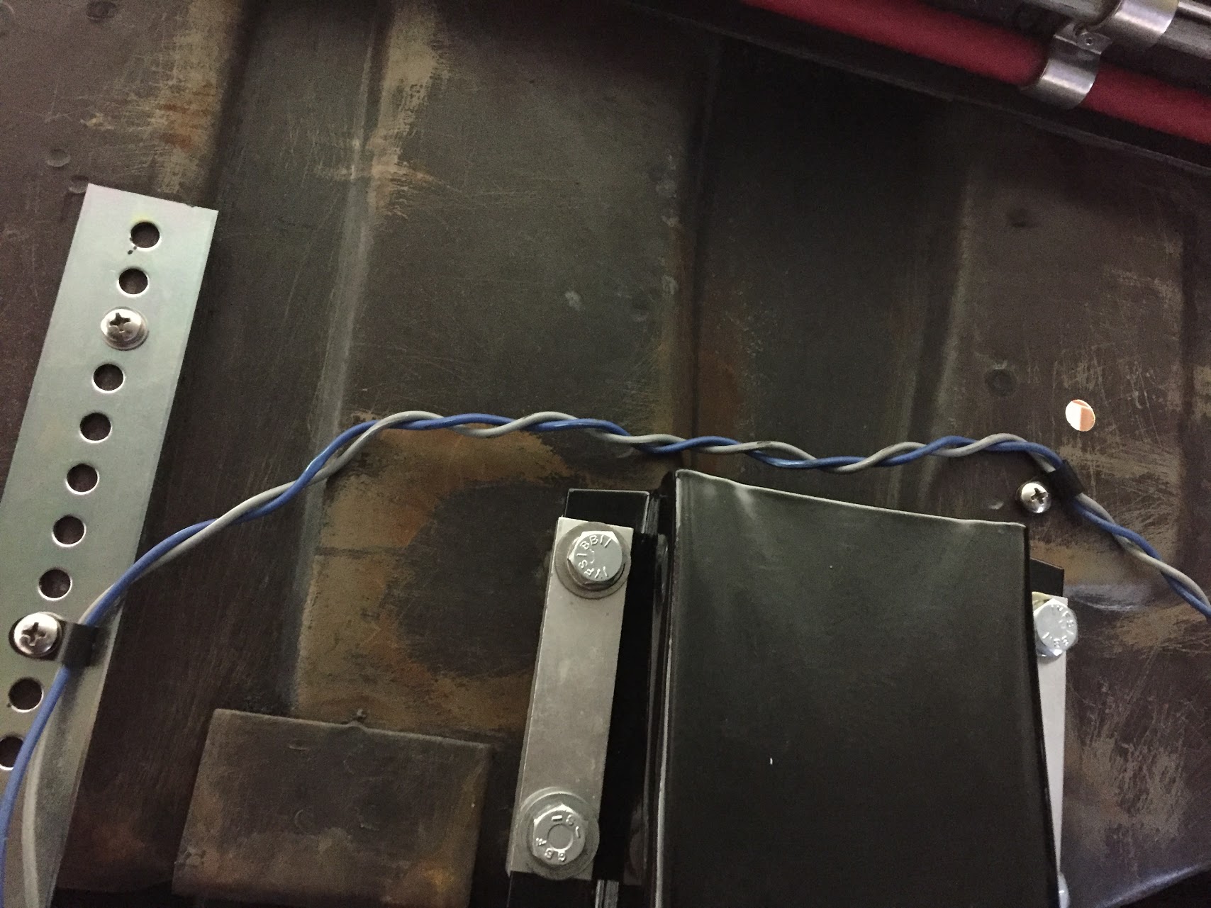
I installed a JL audio premium series master ANL fuse block with a 125 amp “Stinger” ANL style fuse, part number SPF52125 on the lower right portion of the original fuse panel.
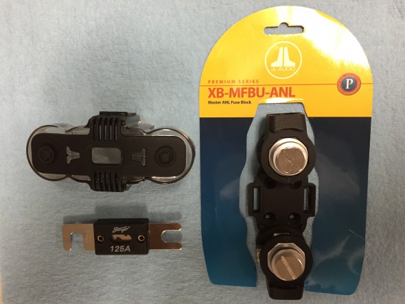
ANL 125 Amp Fuse with J&L Holder
Two three-quarter inch long machine screws were used to secure the fuse block to the panel. On one I was able to take advantage of the 10–32 captured nut that was already on the fuse panel, and on the other I used a nutsert with the 10-24 screw.
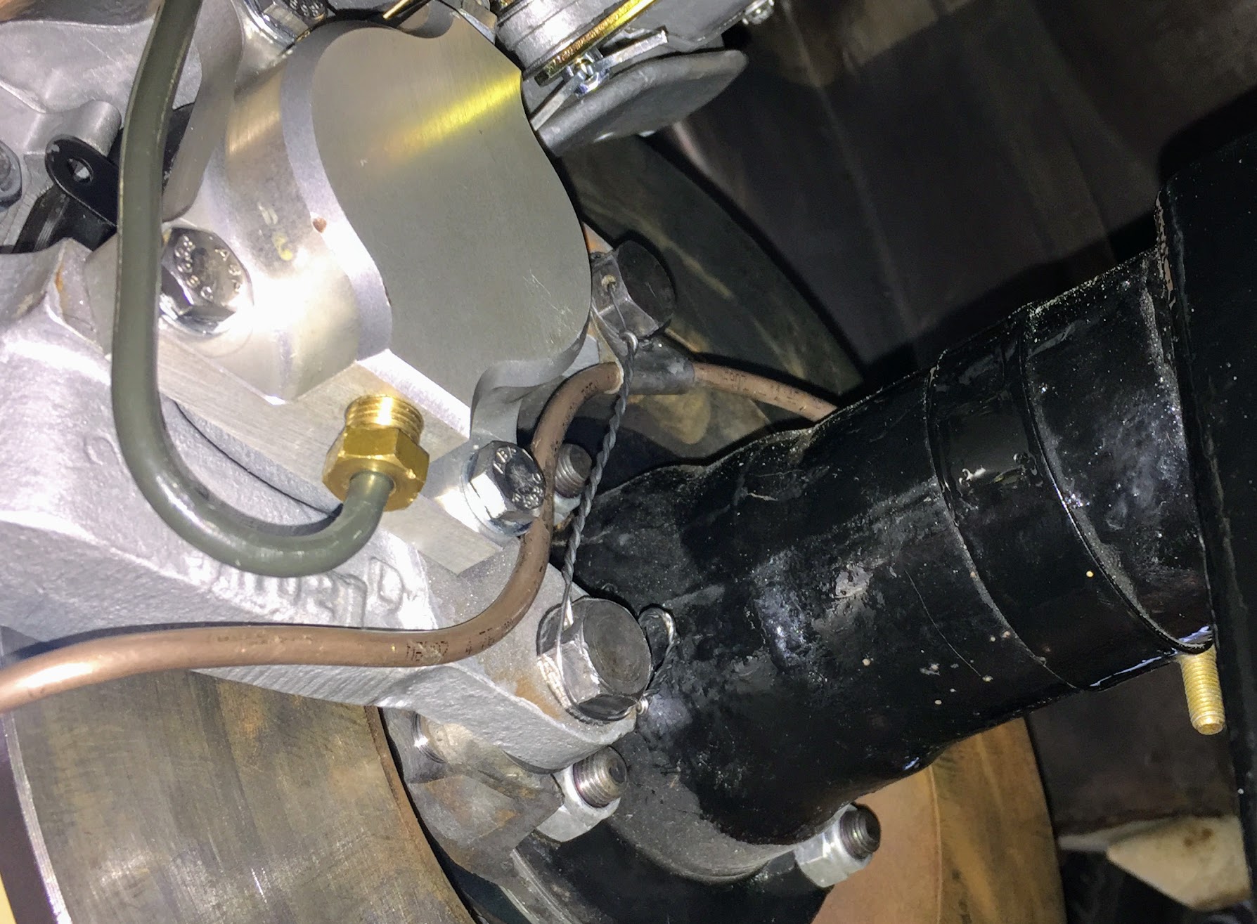
One of the nice features of this particular fuse block is that the ProStar hexagonal posts can be rotated so that the cable can approach from almost any angle. As you can see in the photo, I took advantage of this feature. After the engine is installed, the alternator cable will be cut to proper length.
As can be seen in the image, the cable from the ANL fuse connects to a connector block also used for the power steering.
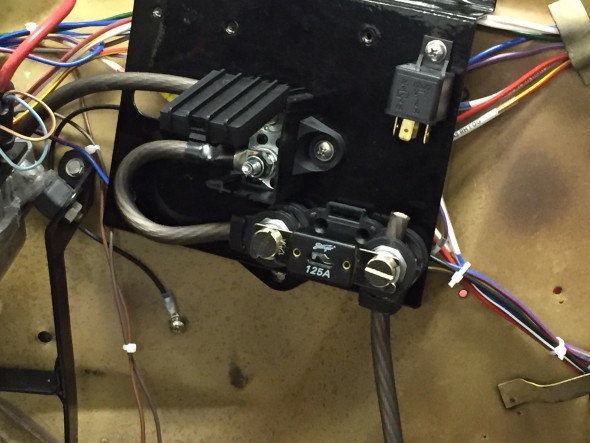
Alternator Fuse Mounted
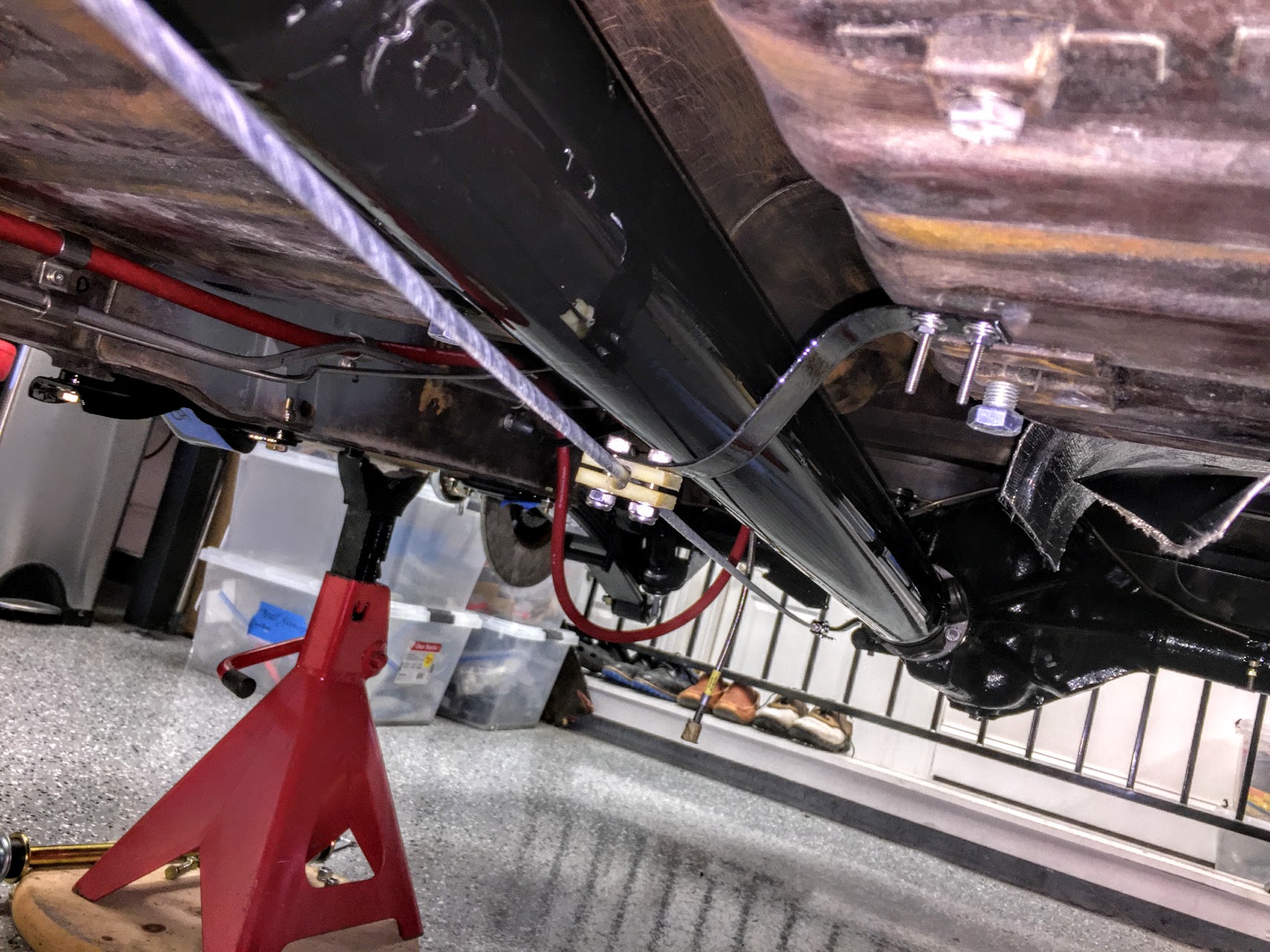
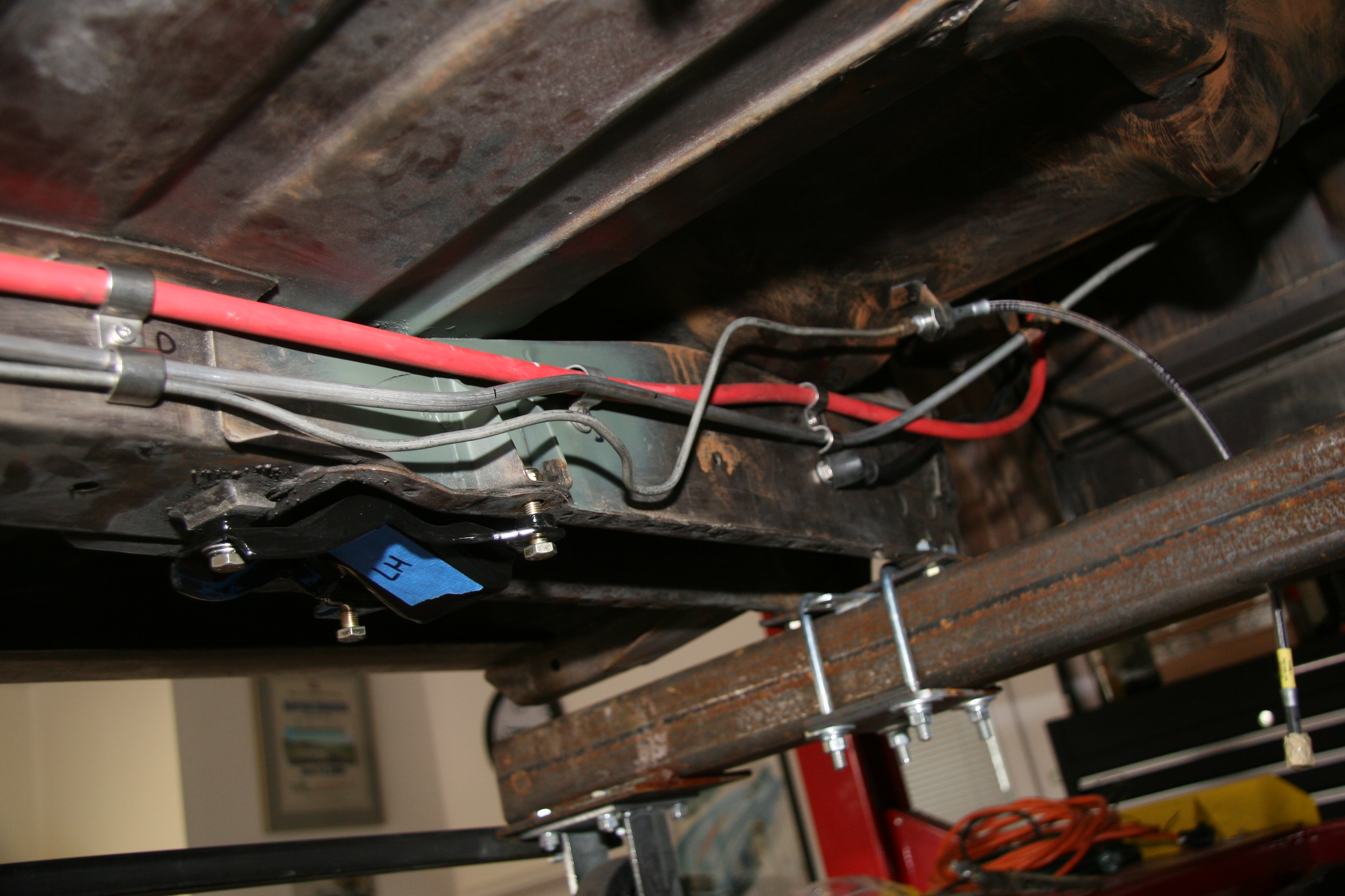
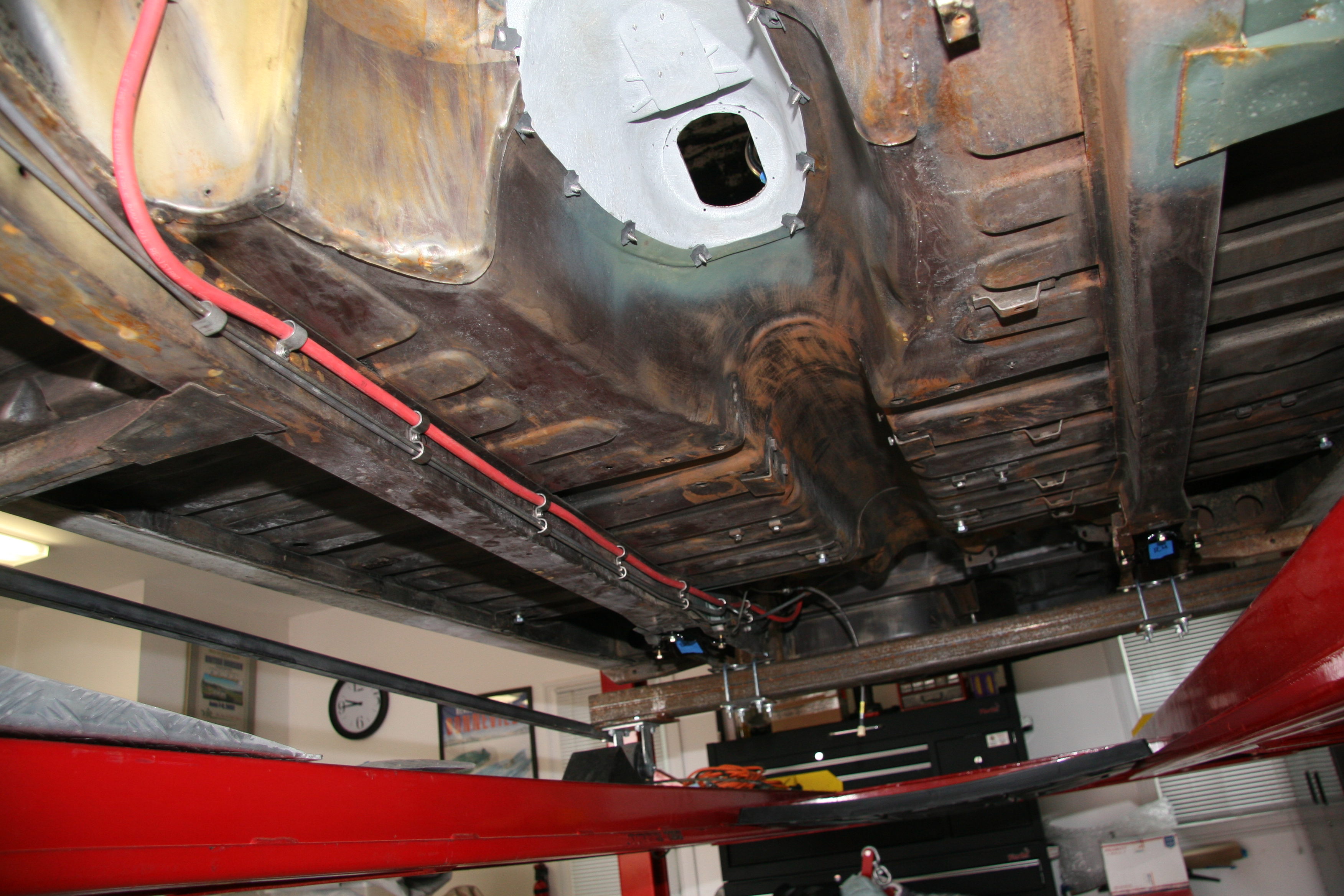
The cable is then routed from the connector block along the LH valance and the firewall to the starter solenoid. It is difficult to track because of all of the in-process wiring, but the path of the alternator cable is visible in the image below:
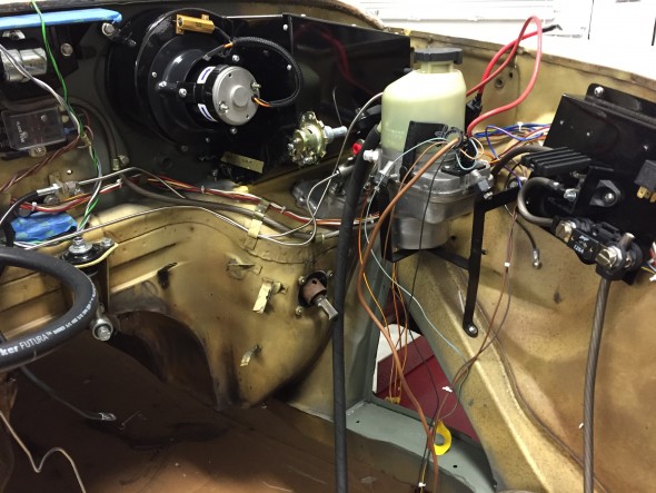
Alternator Cable Wiring
Power Steering Pump
The installation of the power-assisted rack and pinion steering requires the conversion to negative earth and the installation of an alternator replacing the original dynamo/generator. The kit, as supplied, provided a Lucas 80 amp LMA 604 alternator. However, due to other electrical requirements I chose to upgrade to a 120 amp Hitachi alternator. Details about the alternator are found at this link: https://valvechatter.com/?p=4113.
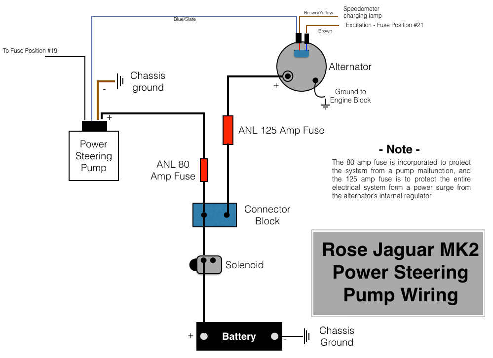
M&C Wilkinson provided wiring instructions, but my configuration is slightly different than in the application they referenced. The wiring diagram below is my interpretation of the wiring required for the pump in my car.
Five wires emanate from the pump. The heavy brown wire connects to ground. The heavy red cable connects to the supplied 80 amp fuse. The 22 gauge black wire connects to the fuse panel at location #19 or #23. The 22 gauge blue/slate wire connects to the alternator at the indicator lamp post.
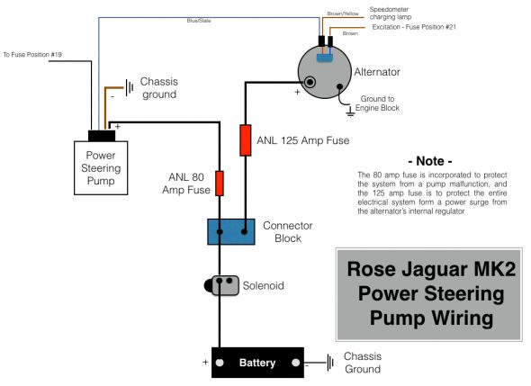
Rose Jaguar MK2 Wiring Diagram for Electric Power Steering Pump
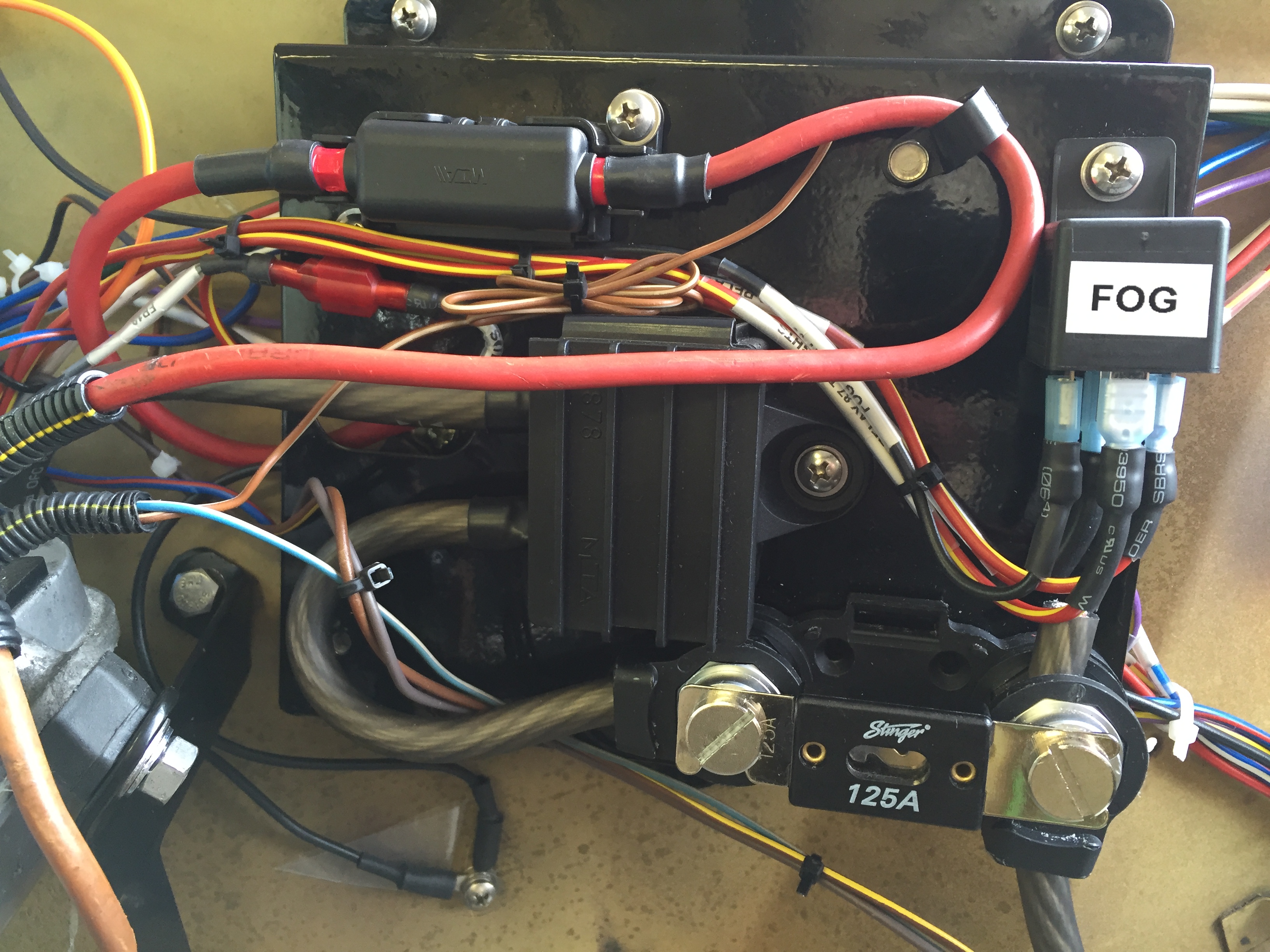
In this image I have installed the 80 amp fuse for the power steering pump. The Bosch relay will be used for the Fogranger fog lamps. All of this will be out of view once the black sheet metal cover his made for the panel.
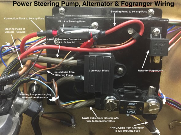
Power Steering Pump, Alternator & Fogranger Wiring on Electrical Panel
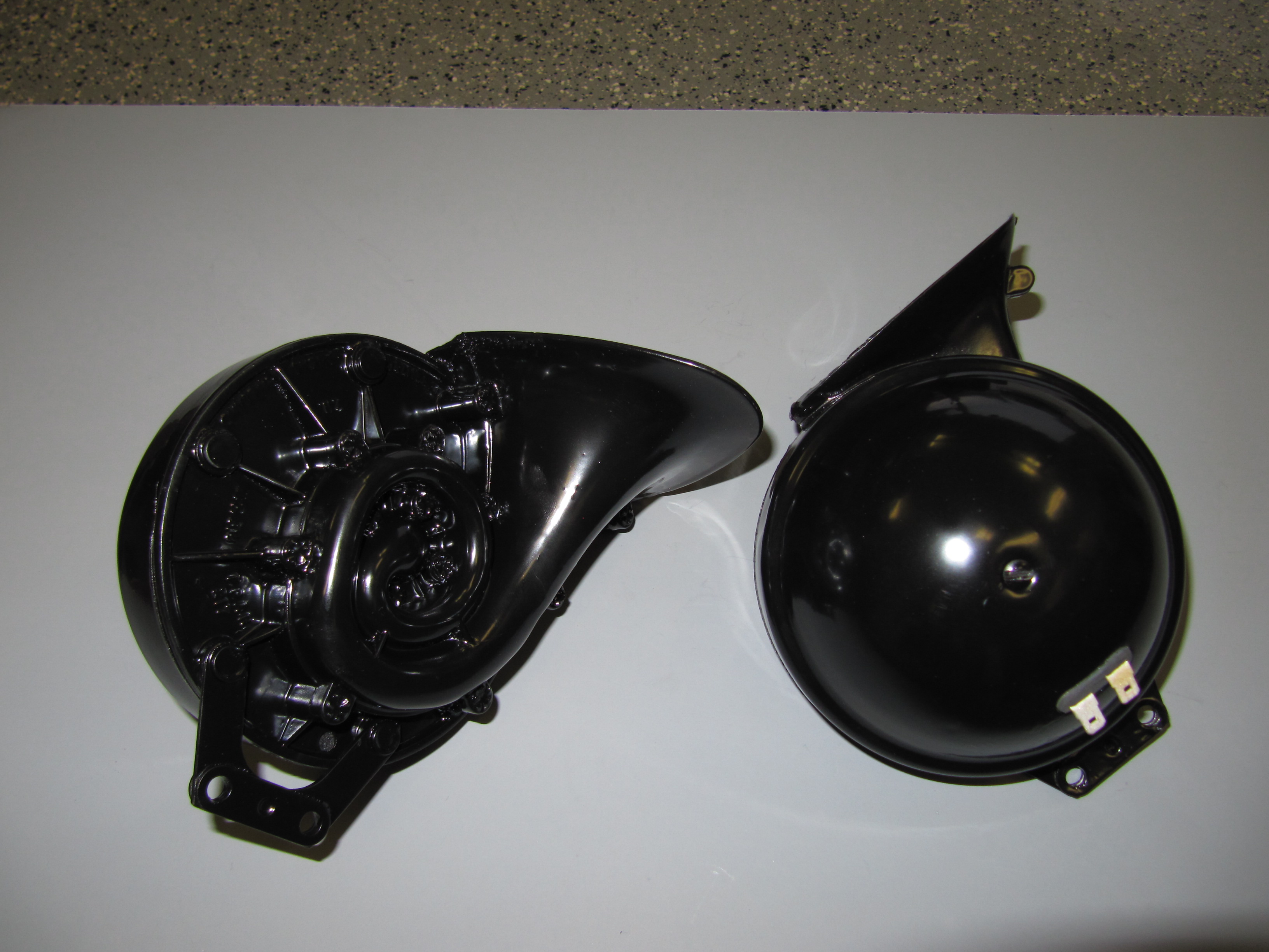
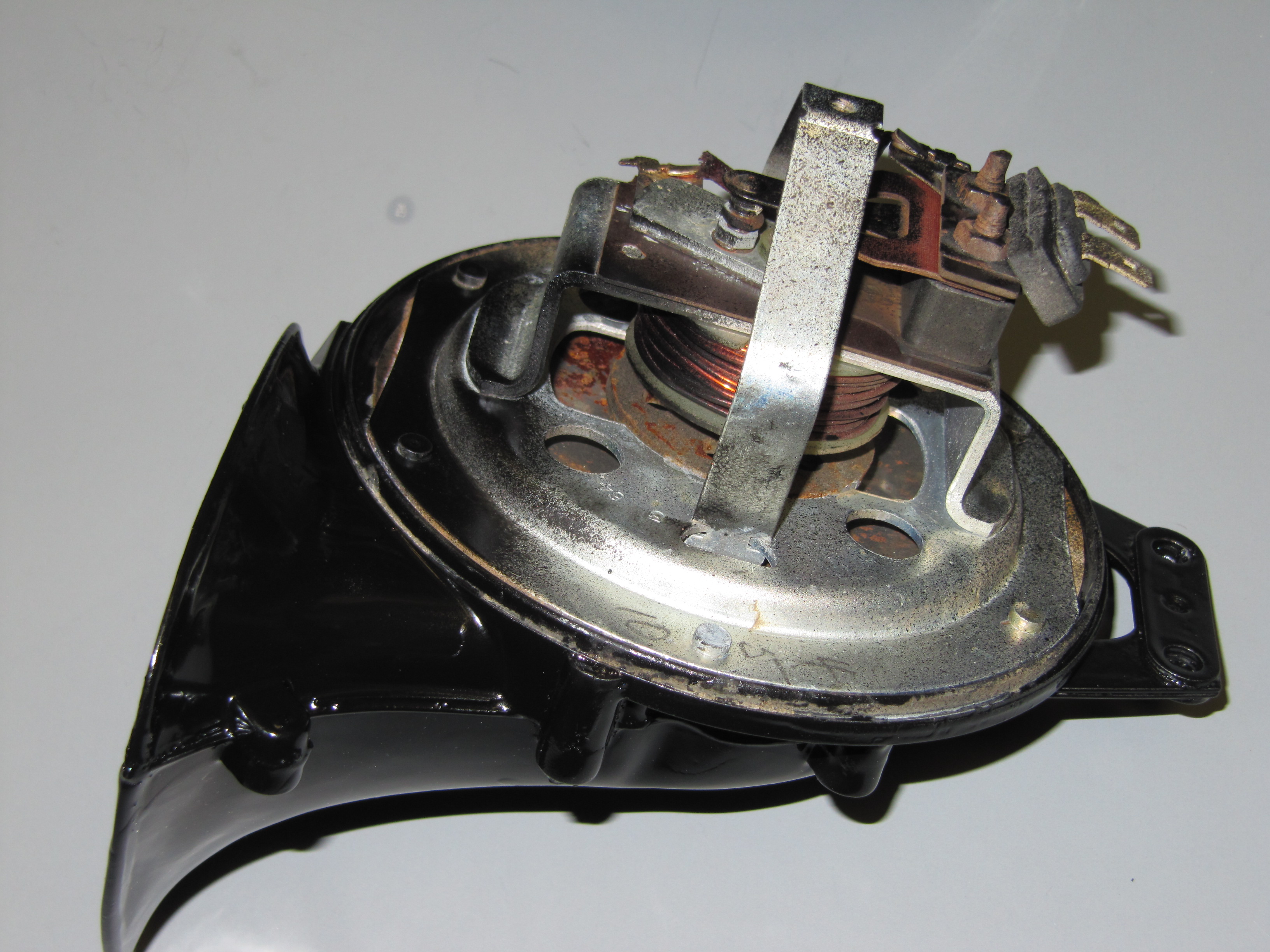
Heater Fan Wiring
A full description of the restoration and modification of the heater box and fan may be found at the Heater Post on this Valvechatter website. The following information addresses the wiring of the heater fan.
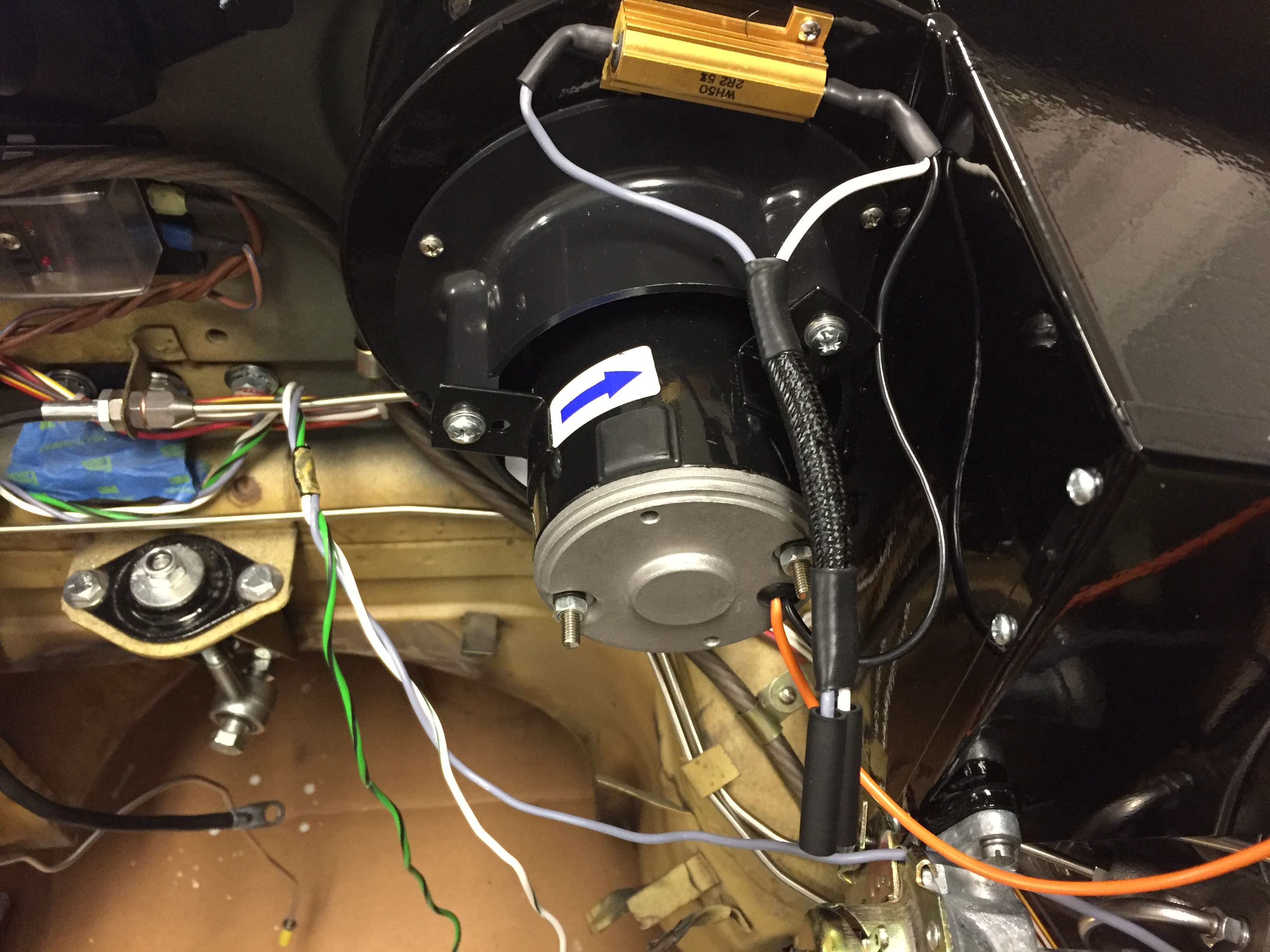
The orange wire from the motor is connected to ground. The black wire to the “inside” post (closest to the heater box) of the resistor. The slate wire from terminal #6 on the switch is connected to the “outside” post (closest to the blower fan) of the resistor. The white/green wire from terminal #8 on the switch connects to the “inside” post on the resistor. The green/yellow wire from the #4 terminal of the switch is connected to the fuse position #11 for power. With this wiring in place, the lower position of the switch is “off,” the middle position is “Low Speed” and the upper position is “High Speed.”
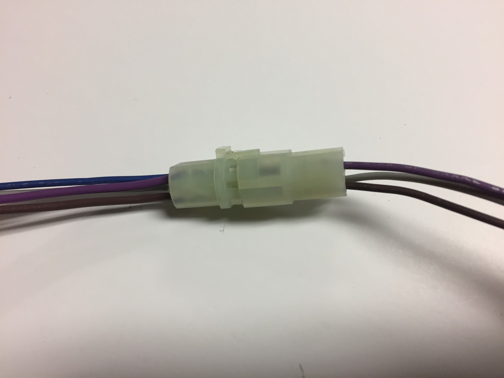
I created a pigtail (seen below) from the resistor for the heater fan wiring. Two wires in the pigtail are connected through two-way snap connectors to wires of the same color which route through the firewall and ultimately back to the Fan Switch. The black wire in the pigtail goes directly to the fan motor. The orange wire from the motor is the ground and it is connected to the LH valance grounding terminal strip.

Heater Fan Wiring
Heater Fan Wiring
Wiper Motor Wiring
As documented in my post entitled Wiper System Upgrade, I installed a Lucas 29W wiper motor kit from Classic Motor Cars in the UK. The upgrade includes a relay mounted behind the central instrument panel assembly. The wiring for the wiper switch is referenced above under the section “Instrument Panel Assembly Switch Wiring.” This is a diagram of the wiring:
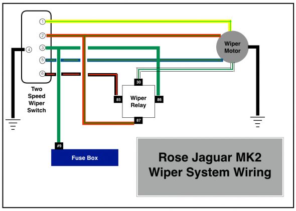
Rose Jaguar MK2 Wiper System Wiring
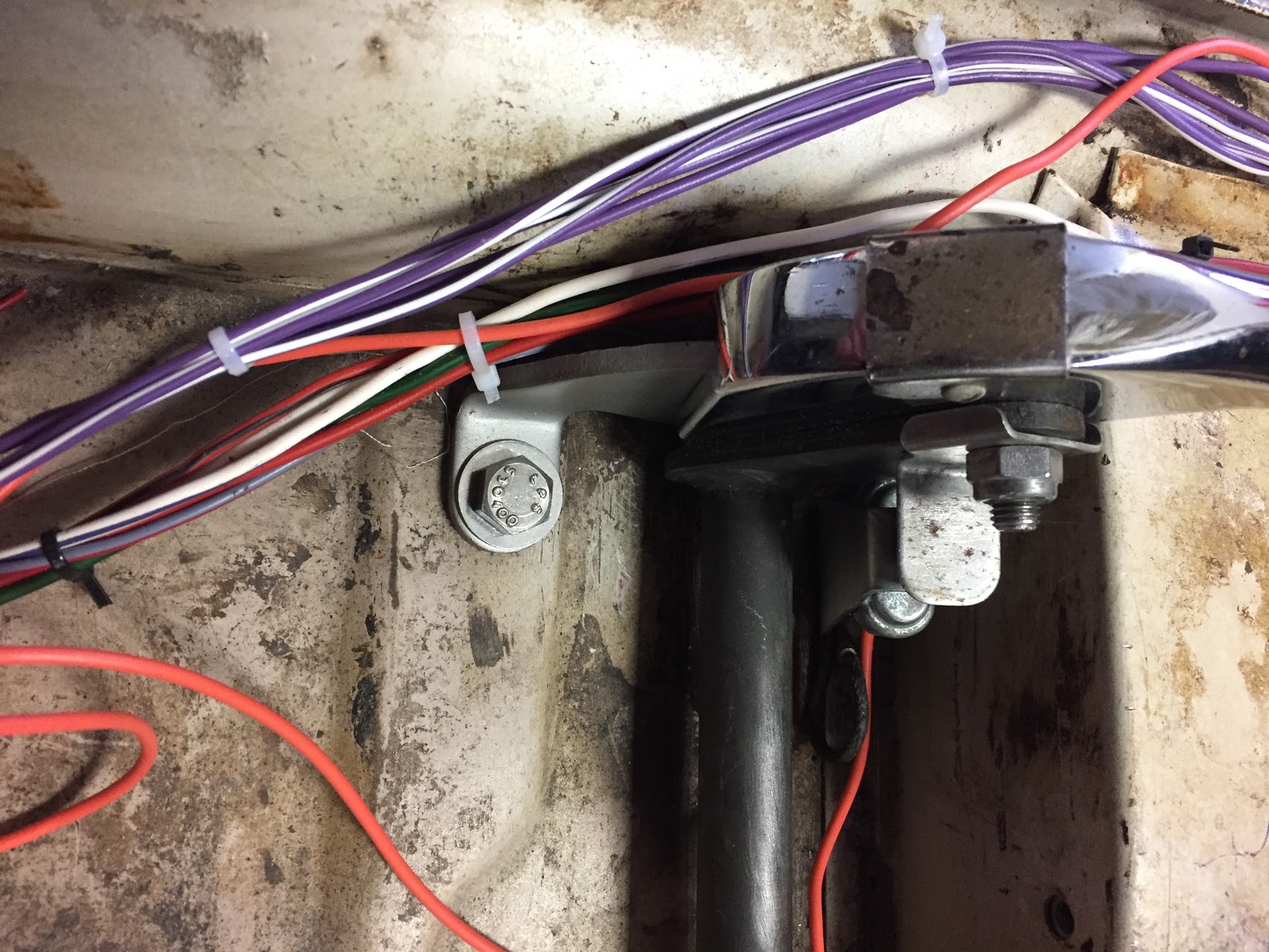
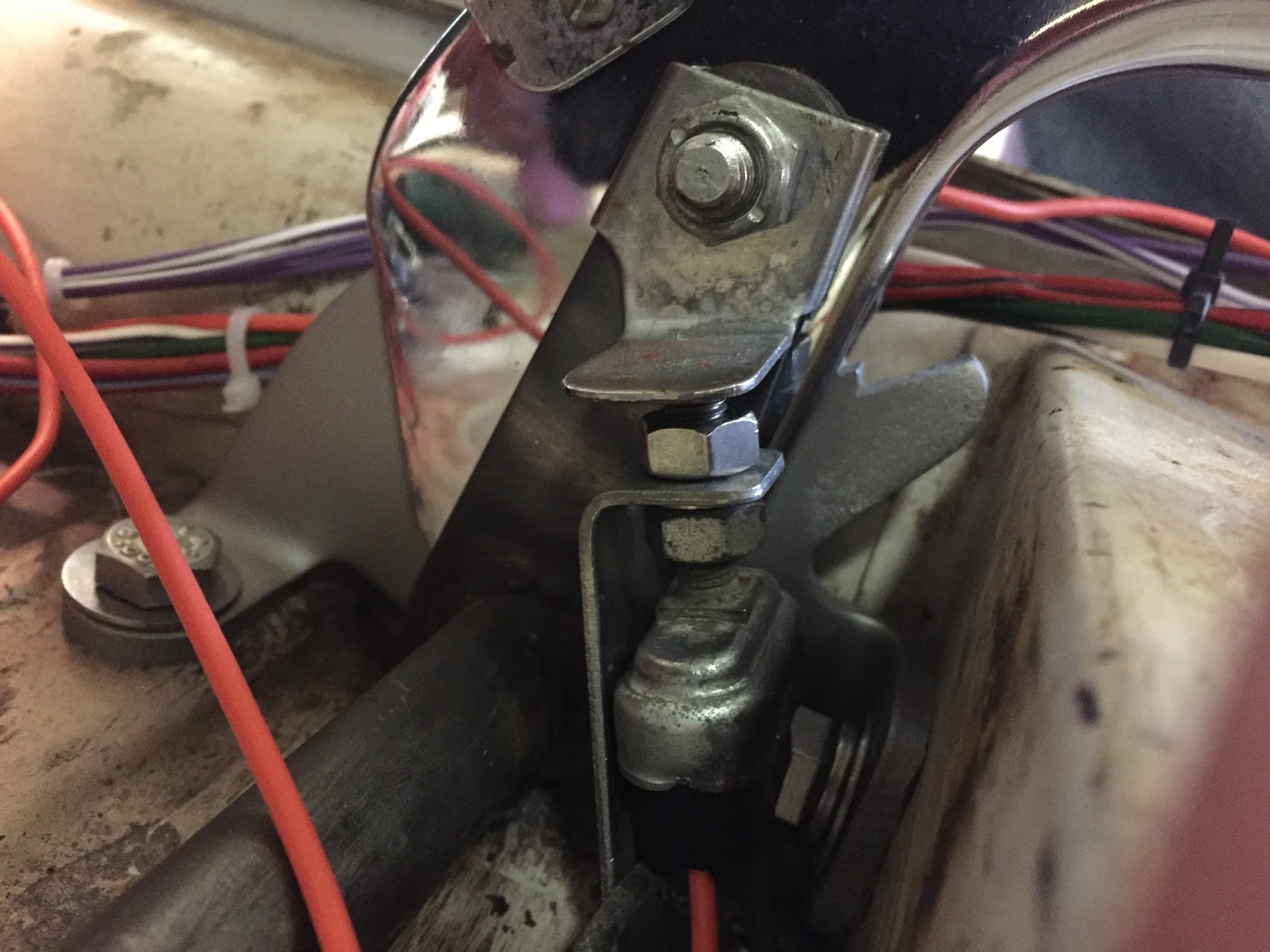
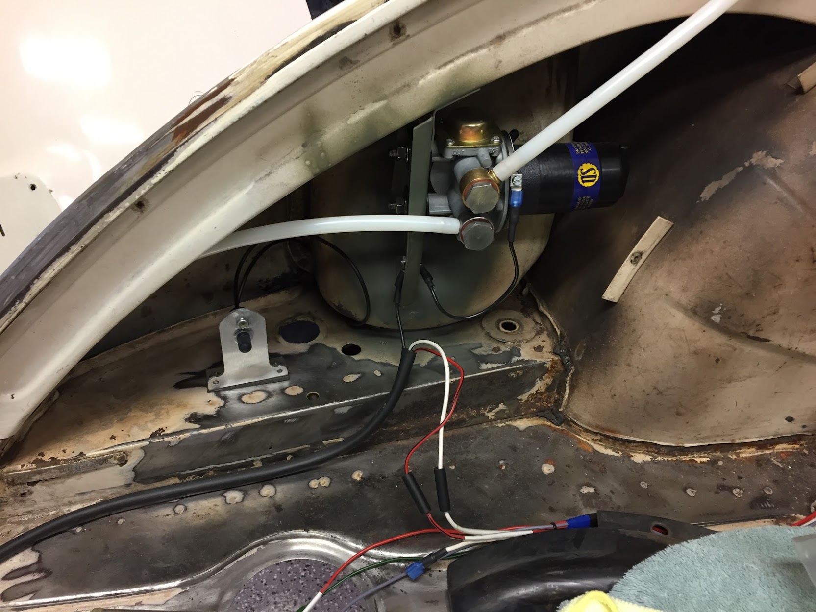
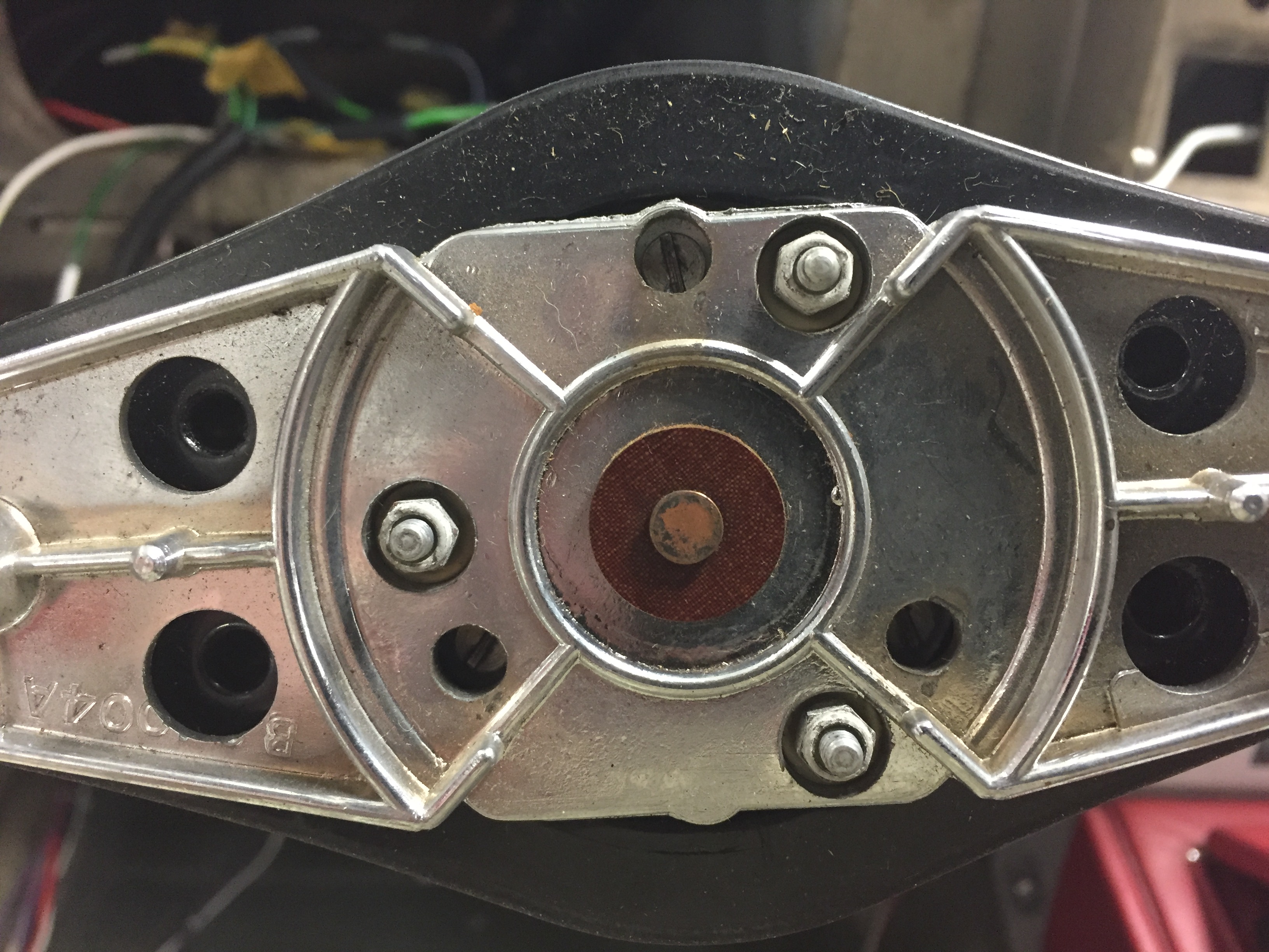
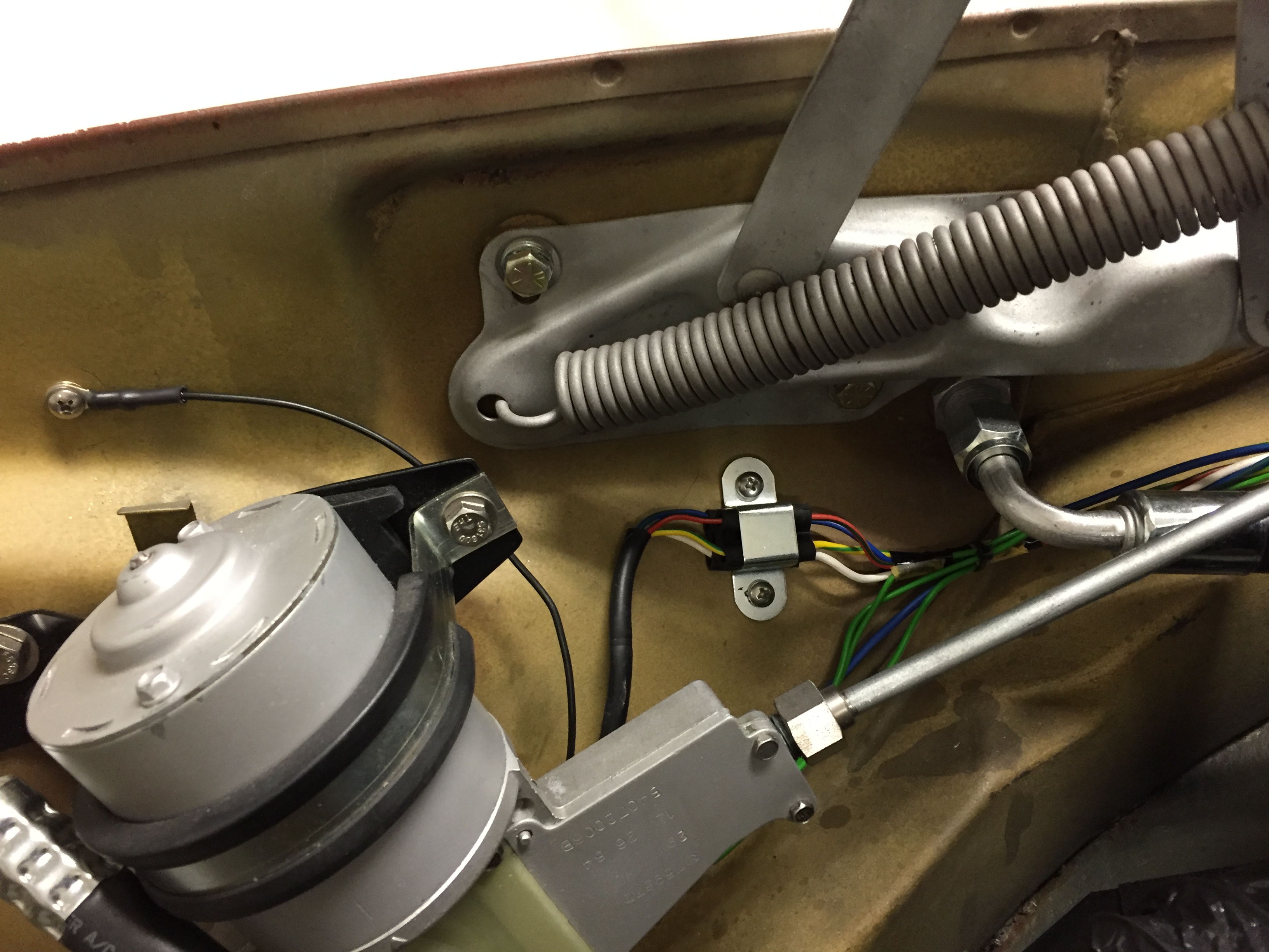
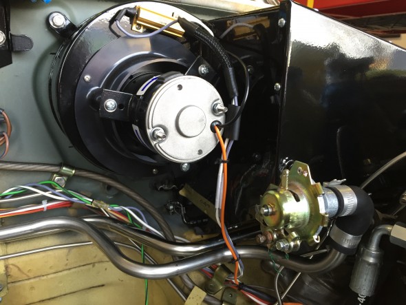
This is an image of the wiper motor mounting. I used eight of the ten connection points in a ten-way rubber snap connector and fastened it to engine bay RH valance with an original type retaining clasp. note the wiper motor ground connection to the upper left.

Wiper Motor Mount and Wiring
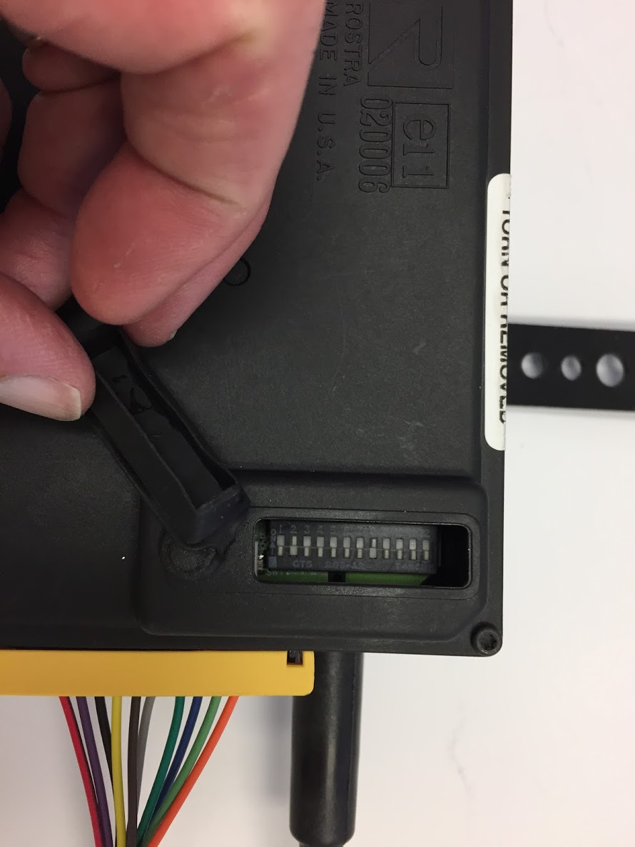
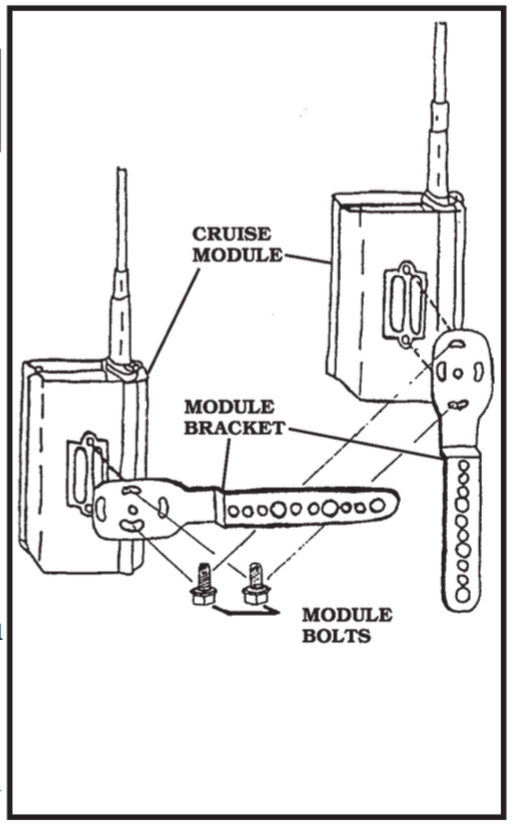
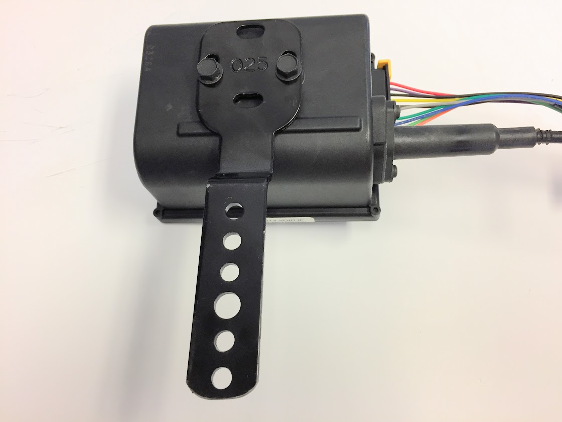
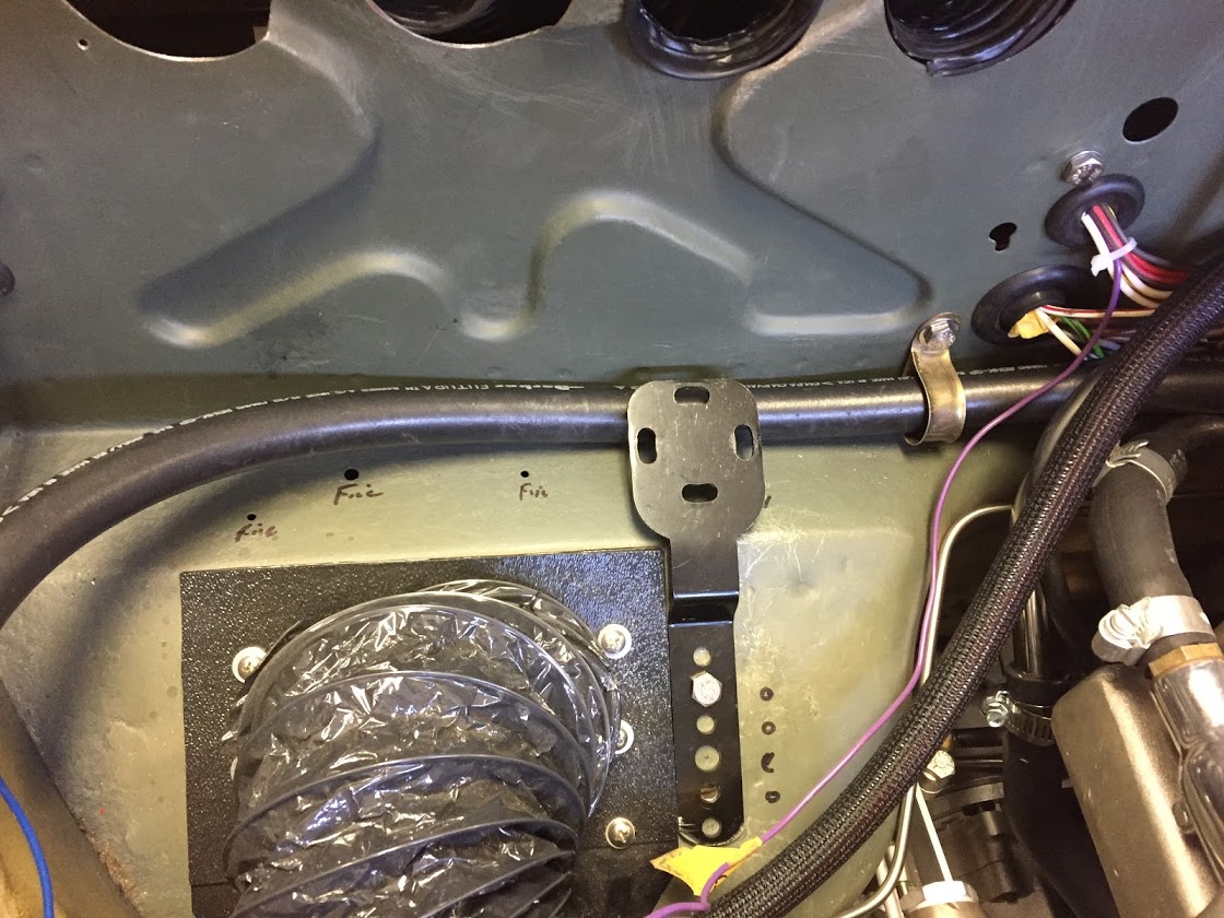
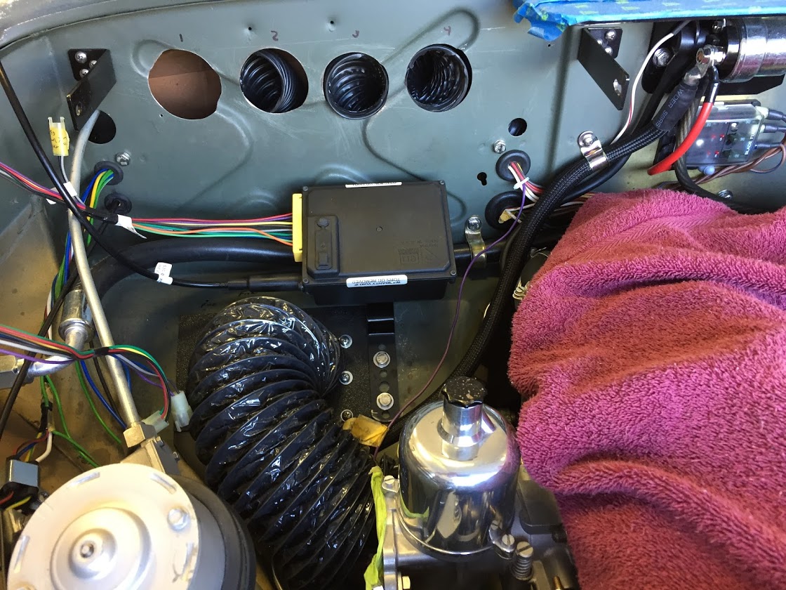
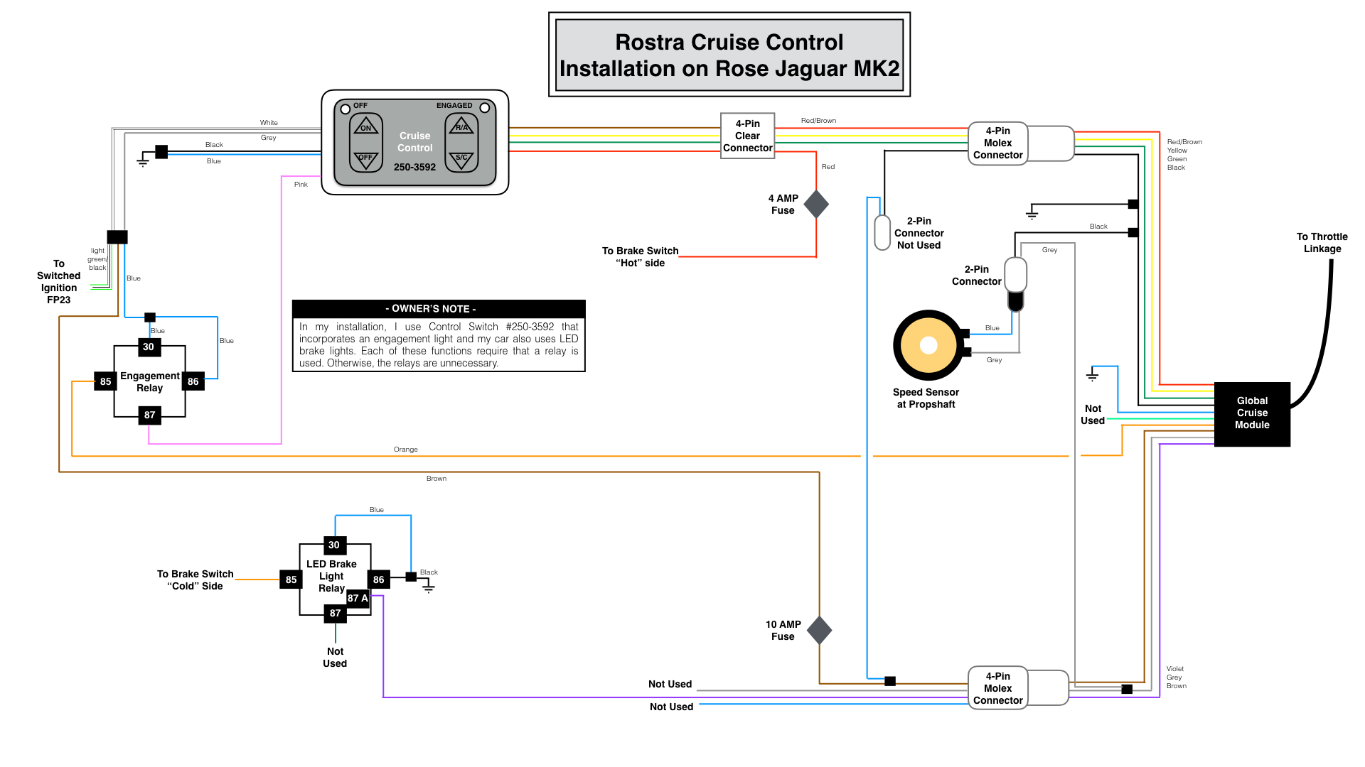
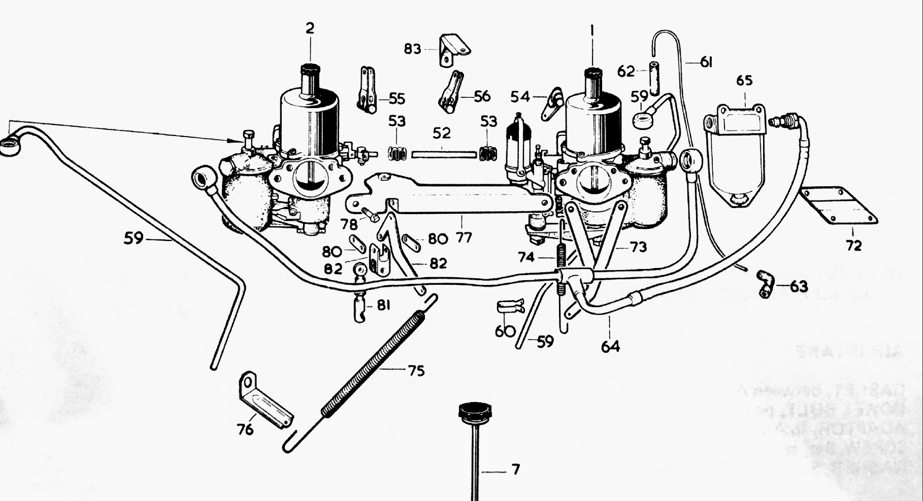
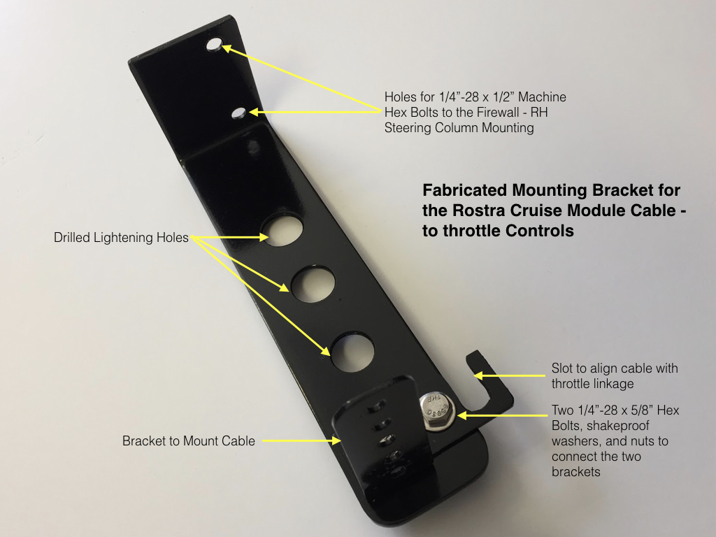
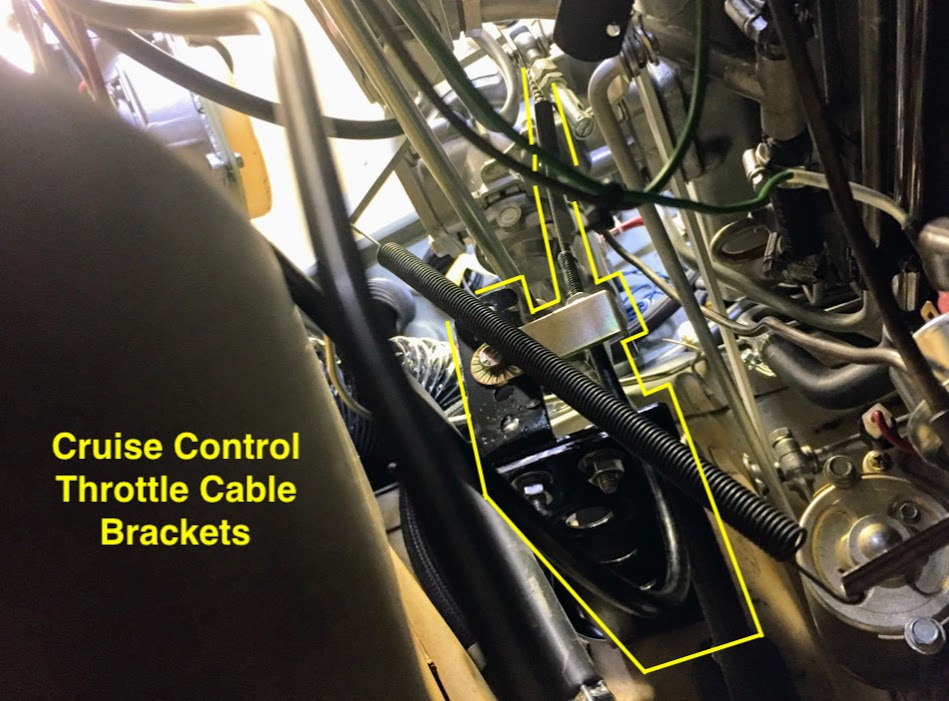
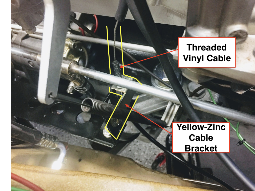
Cruise Control Wiring
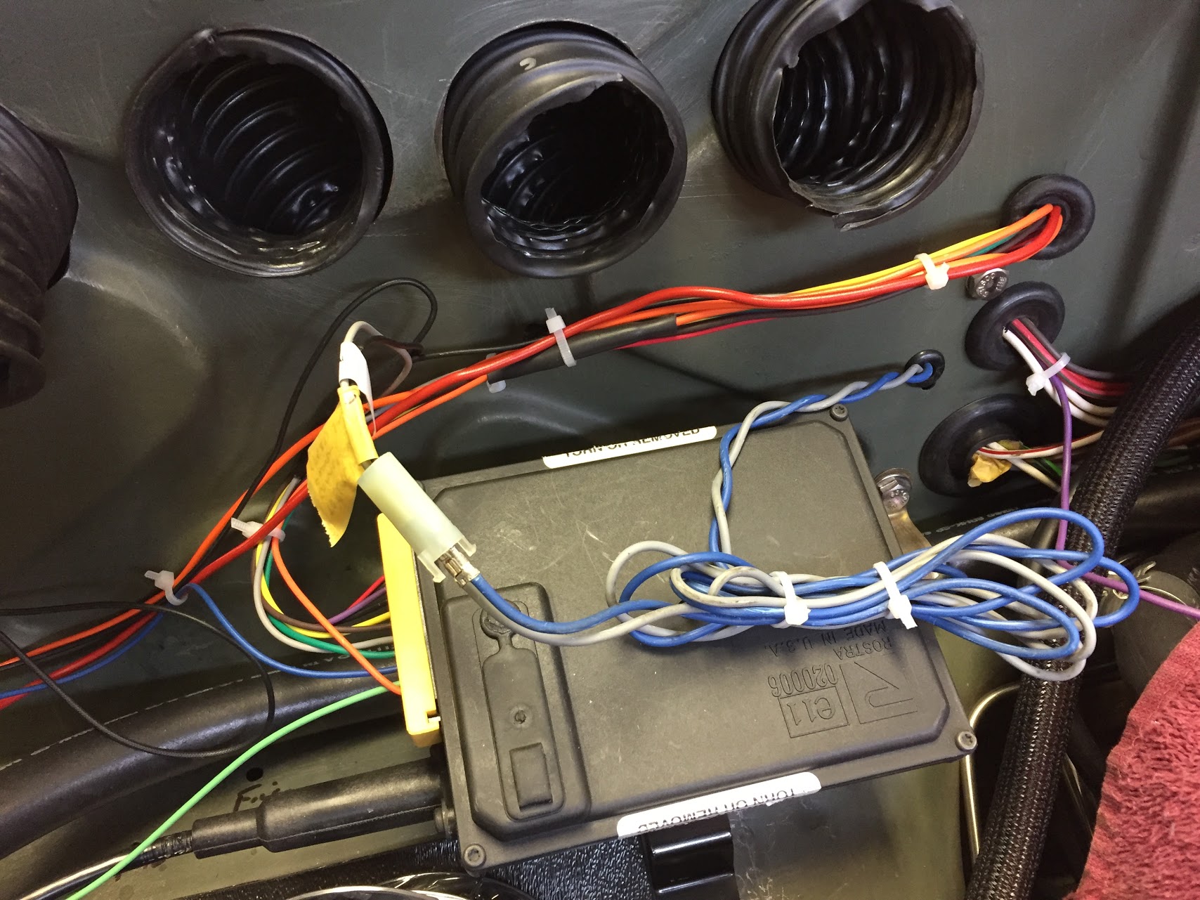
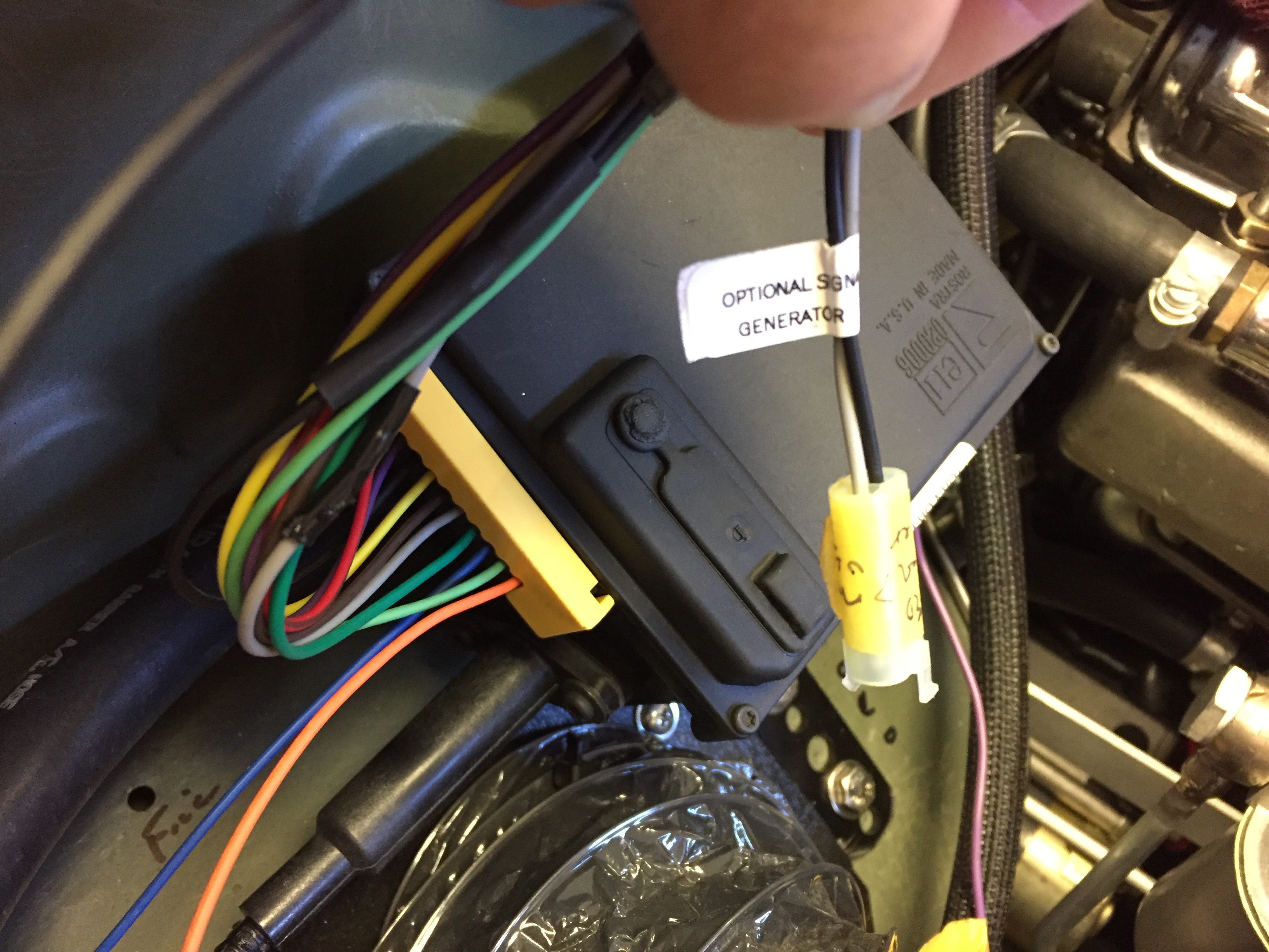
A full description of the installation of the Rostra Cruise Control System in my MK2 is provided in the MK2 Cruise Control Post. My wiring diagram, tailored for my 1964 Jaguar MK2 application, is provided below. As the disclaimer above indicates, the wiring description in this post journals what I did for my car. It is not my intention to describe what you should do for your car!
This is a link to a pdf of the wiring diagram and it is also shown in the image below:
rostra-cruise-control-wiring-for-jag-mk2
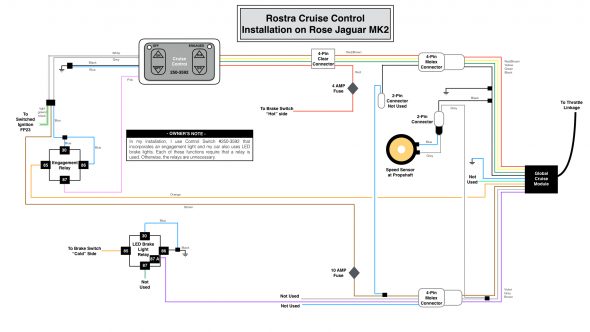
Rostar Cruise Control Wiring for the Rose MK2
Central Locking and Keyless Entry Wiring
A full description of the locking system may be found at the “Remote Control Door Locks web site entry: https://valvechatter.com/?p=9205. The wiring for the system is comprised of two components. The MES Central Locking Control Module operates the door lock actuators. Once that system in properly installed and operating as it should, the AVITAL keyless entry module is added to permit use of a key fob to wirelessly lock and unlock all doors. An added feature of the system is that about fifteen seconds after ignition all doors are locked automatically.
The following wiring diagram is unfortunately a bit busy. This is a link to a pdf file of the diagram: Keyless Entry Power Locks for Rose Jag MK2 and a jpeg file is depicted below:
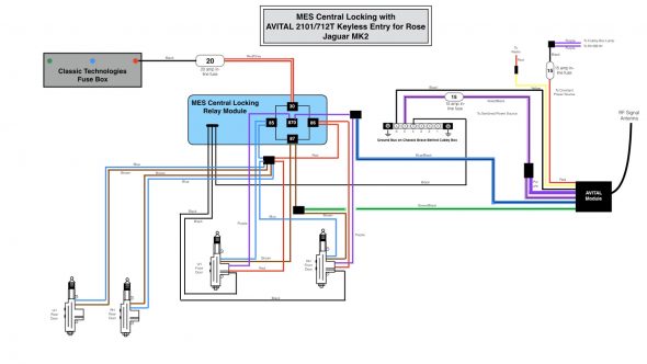
Keyless Entry Power Locks for Rose Jag MK2
Air Conditioner Operating Controls Wiring
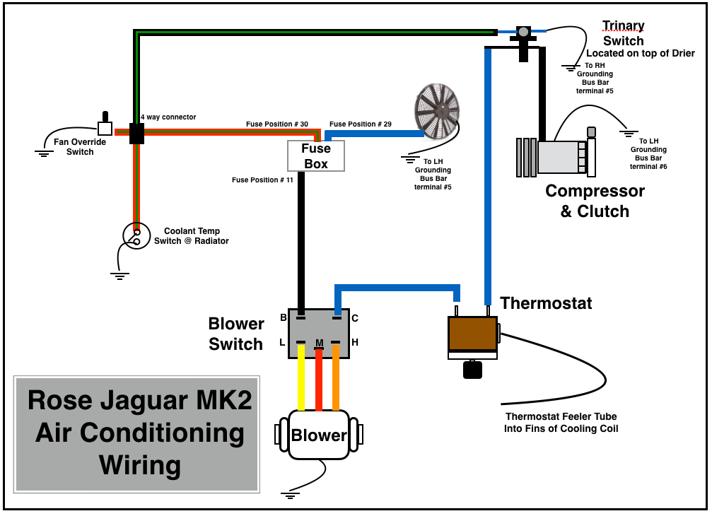
A full description of the installation of the RetroAir air conditioning system in my MK2 is provided in the “Air Conditioning” Post. The wiring of the controls and devices for the air conditioning system is depicted in the following diagram:
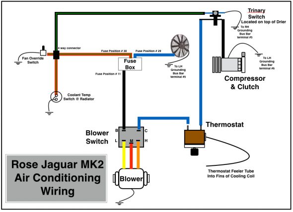
Rose Jaguar MK2 Air Conditioning Wiring
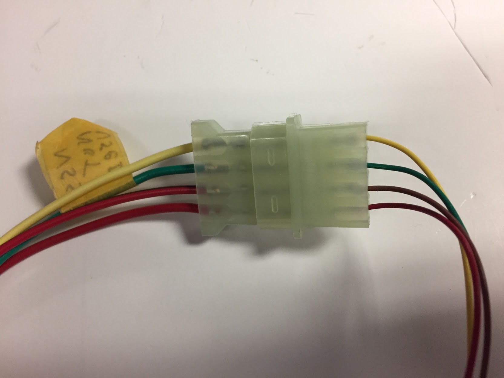
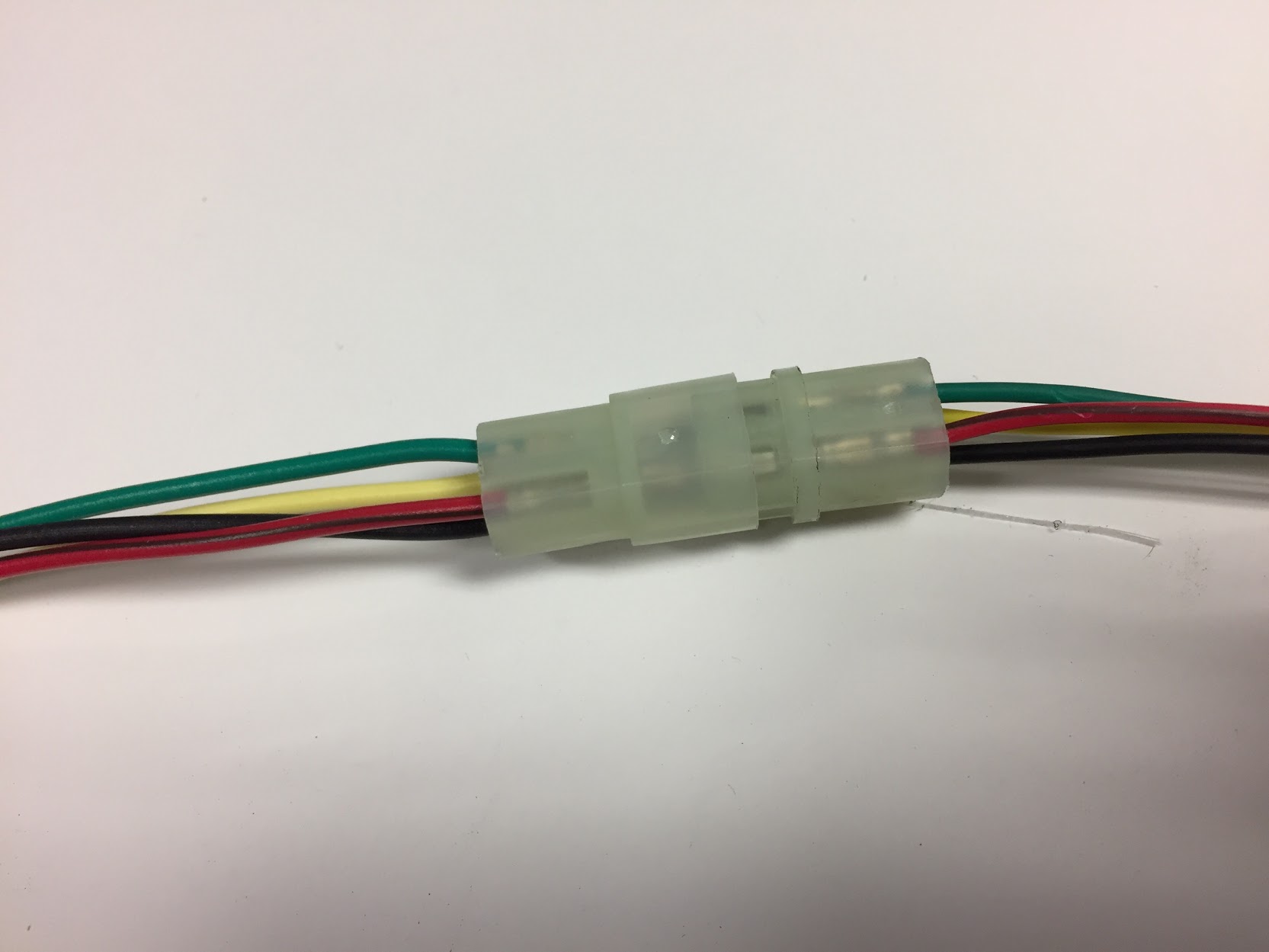
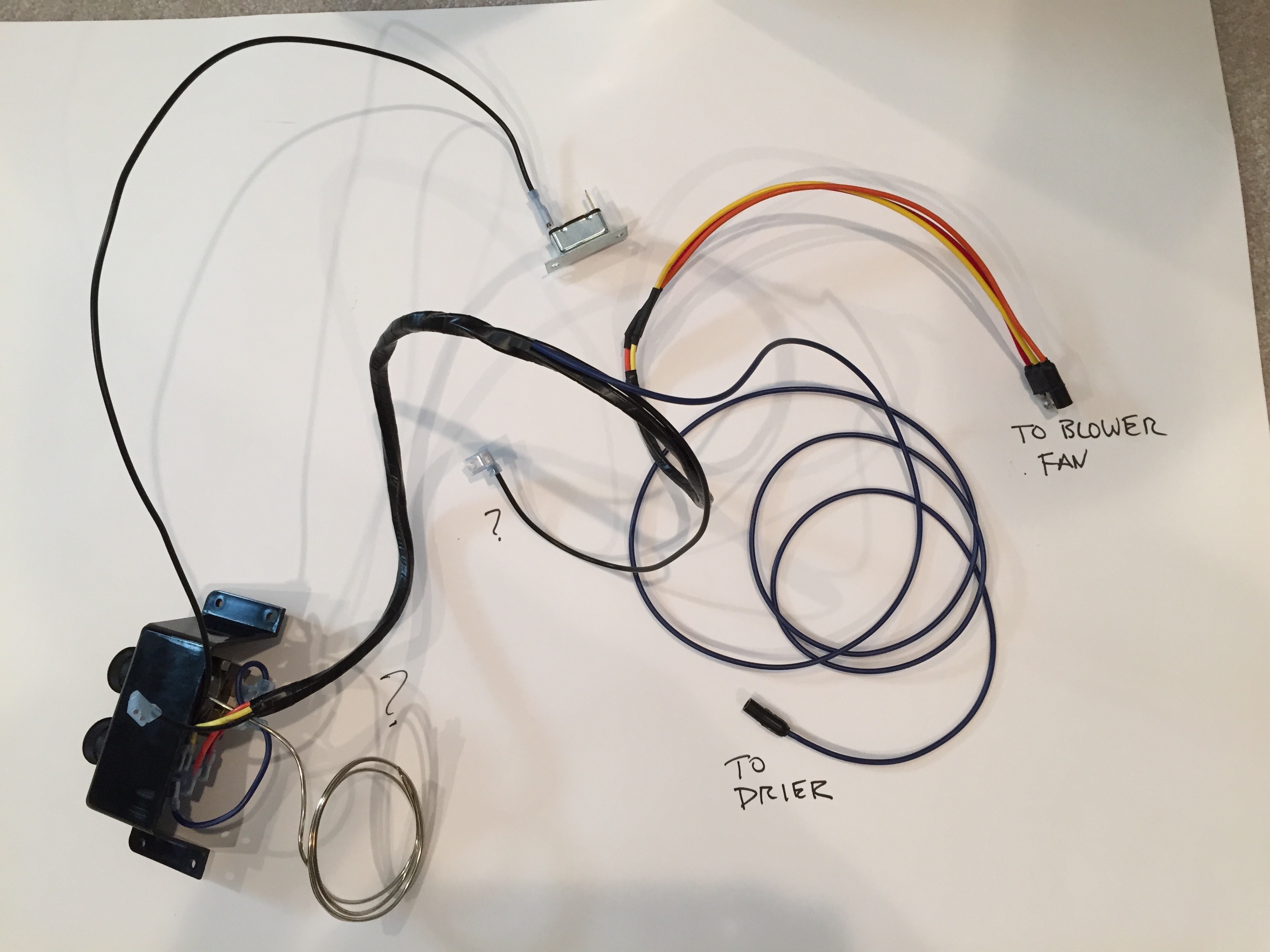
This is a photograph of the wiring harness provided in the RetroAir kit. In my application I did not use the circuit breaker shown in the image because I wired the blower switch directly to the fuse panel and protected the system at that point with a 40 amp fuse.
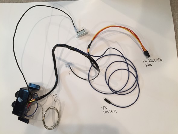
RetroAir Wiring Harness Kit
As the diagram above illustrates, I chose to install a trinary pressure safety switch in the air conditioning electrical circuit. The trinity switch is also discussed in the “Air Conditioning Post.”
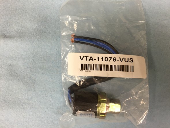
Vintage Air Trinary Switch
The Vintage Air trinary switch kits combine low and high pressure compressor clutch cut-off functions plus an electric fan engagement signal at 254 psi. The low pressure cut-off of these trinary switches is 30 psi and the high pressure cut-off is 406 psi.
http://www.vintageair.com/Instructions2013/904678.pdf
The switch as supplied has two blue wires and two black wires. Because the switch is located in a right from wheel well and exposed to the elements, I connected the four wires to a waterproof connector purchased from British Wiring, and then routed the wires to their termination points. One blue wire is for ground and the other for fused power. One black wire connects to the compressor and the other to the thermostat controller for the air conditioner.
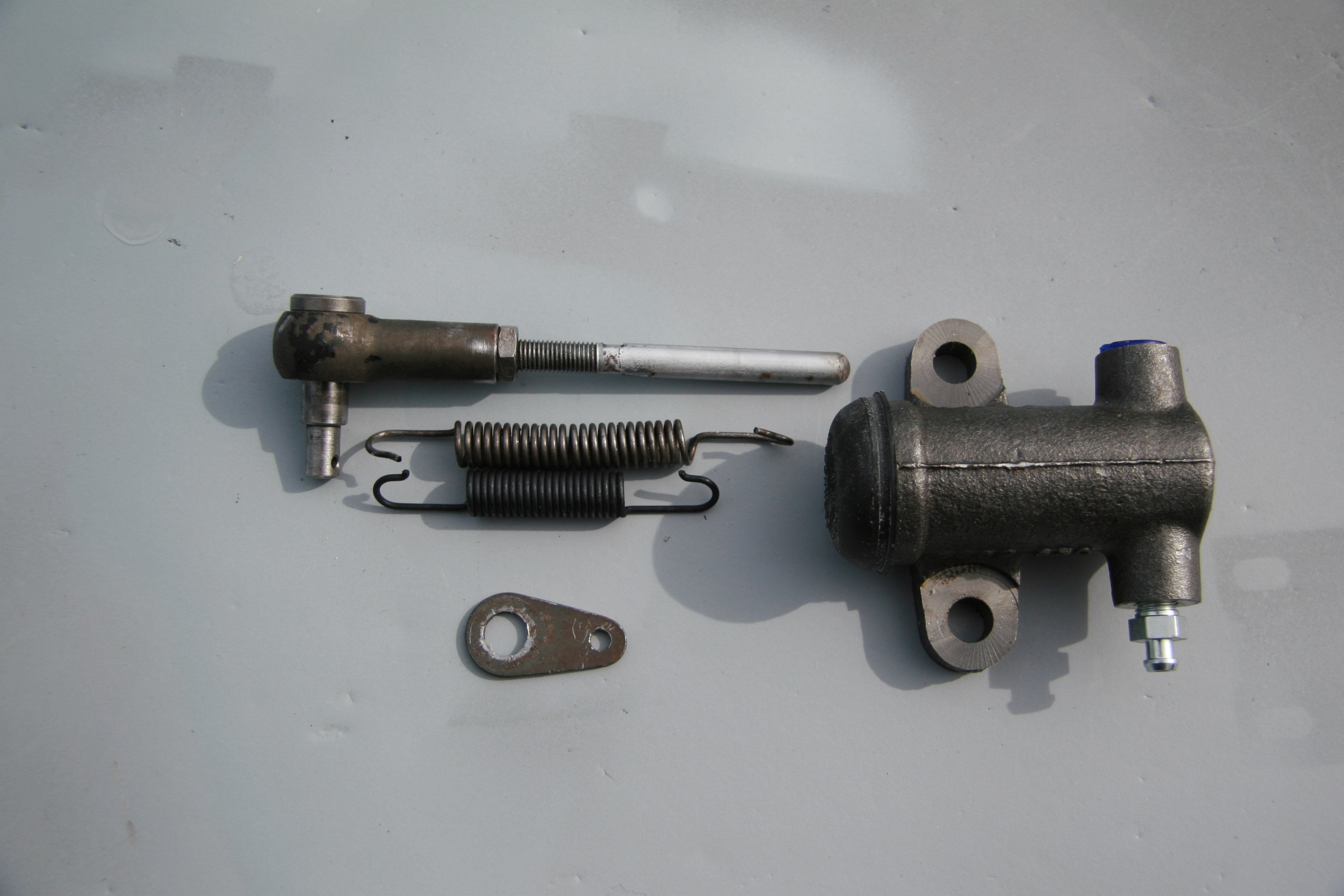
Turn Indicator and Headlamp Flasher Switch at the Steering Column and the Laycock De Normanville Overdrive Switch and Wiring
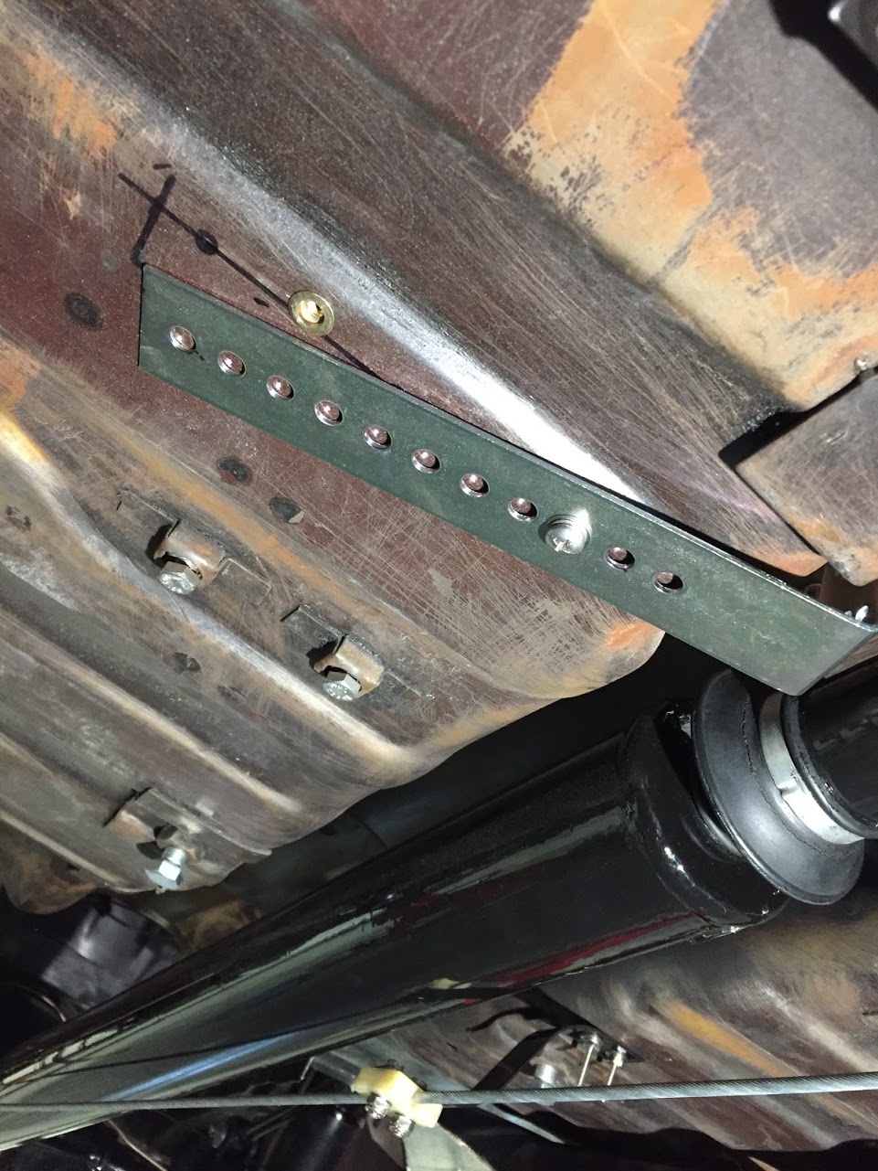
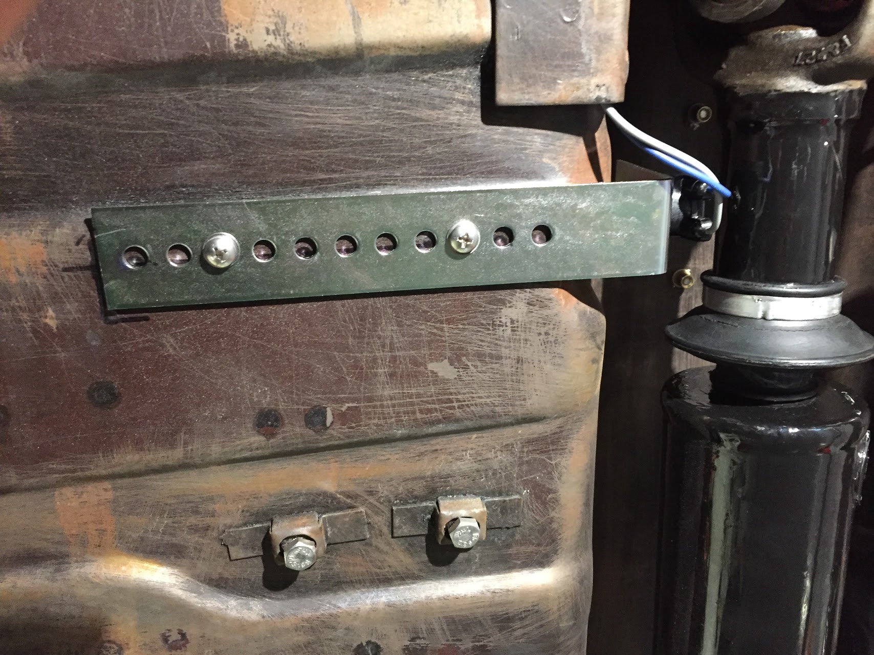
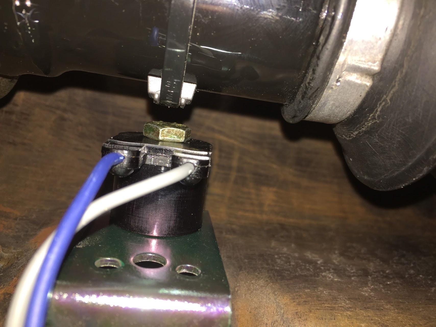
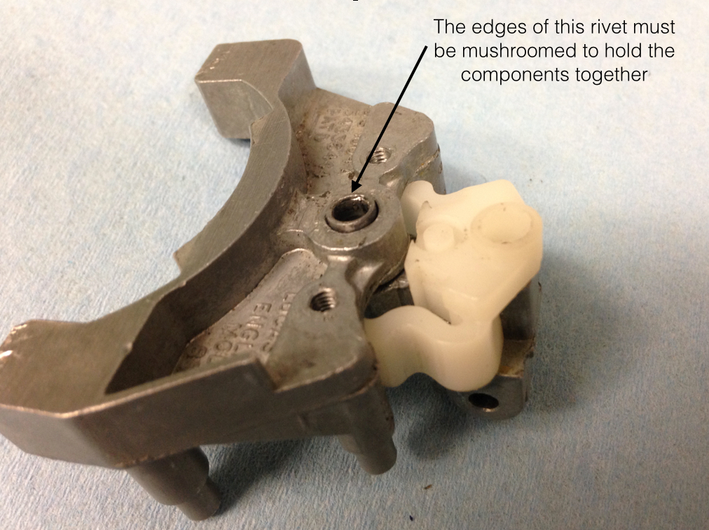
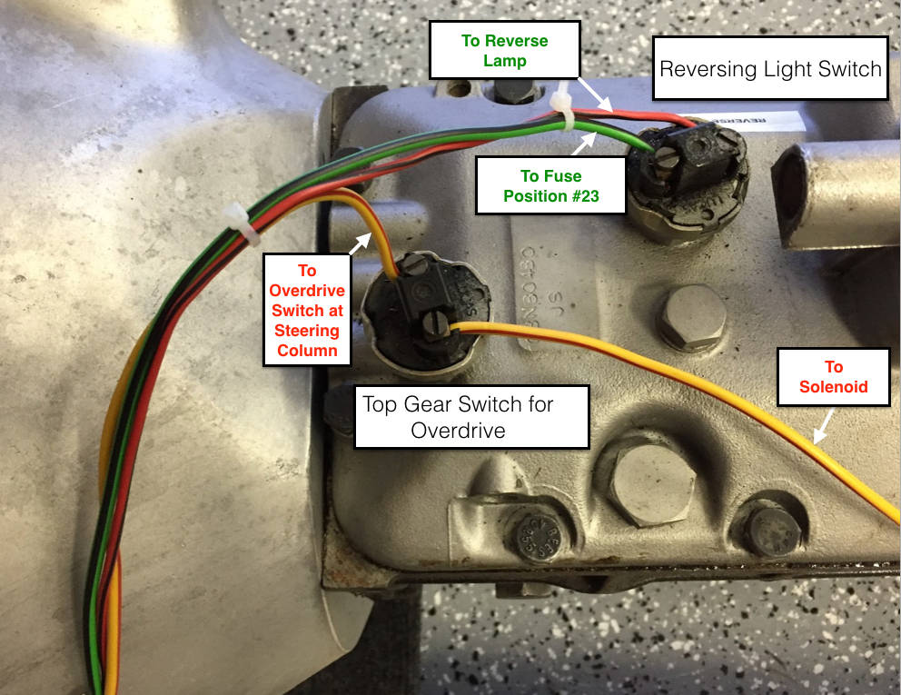
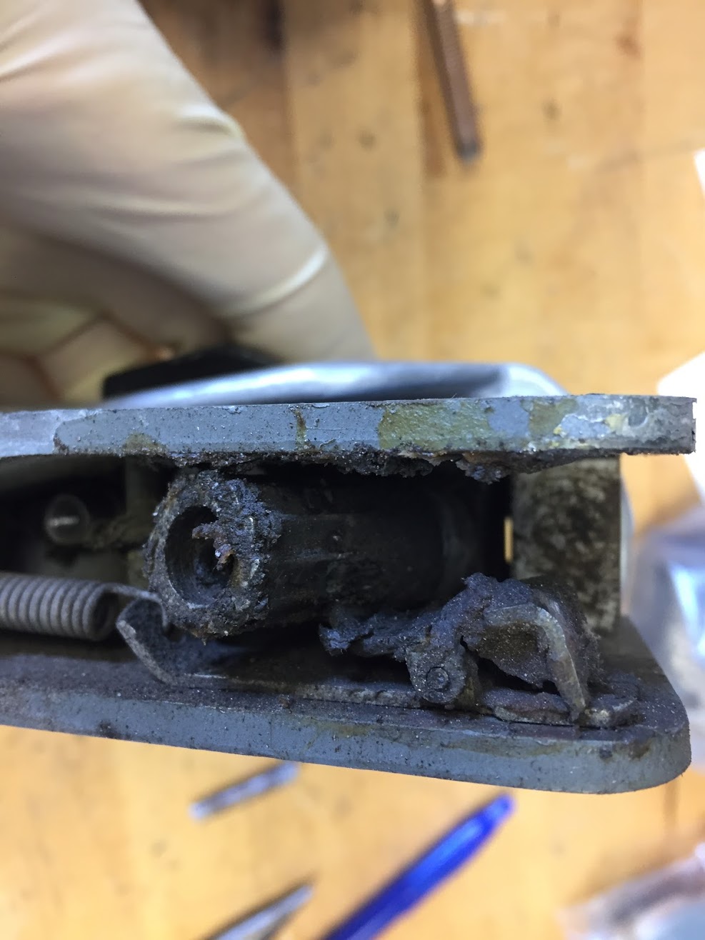
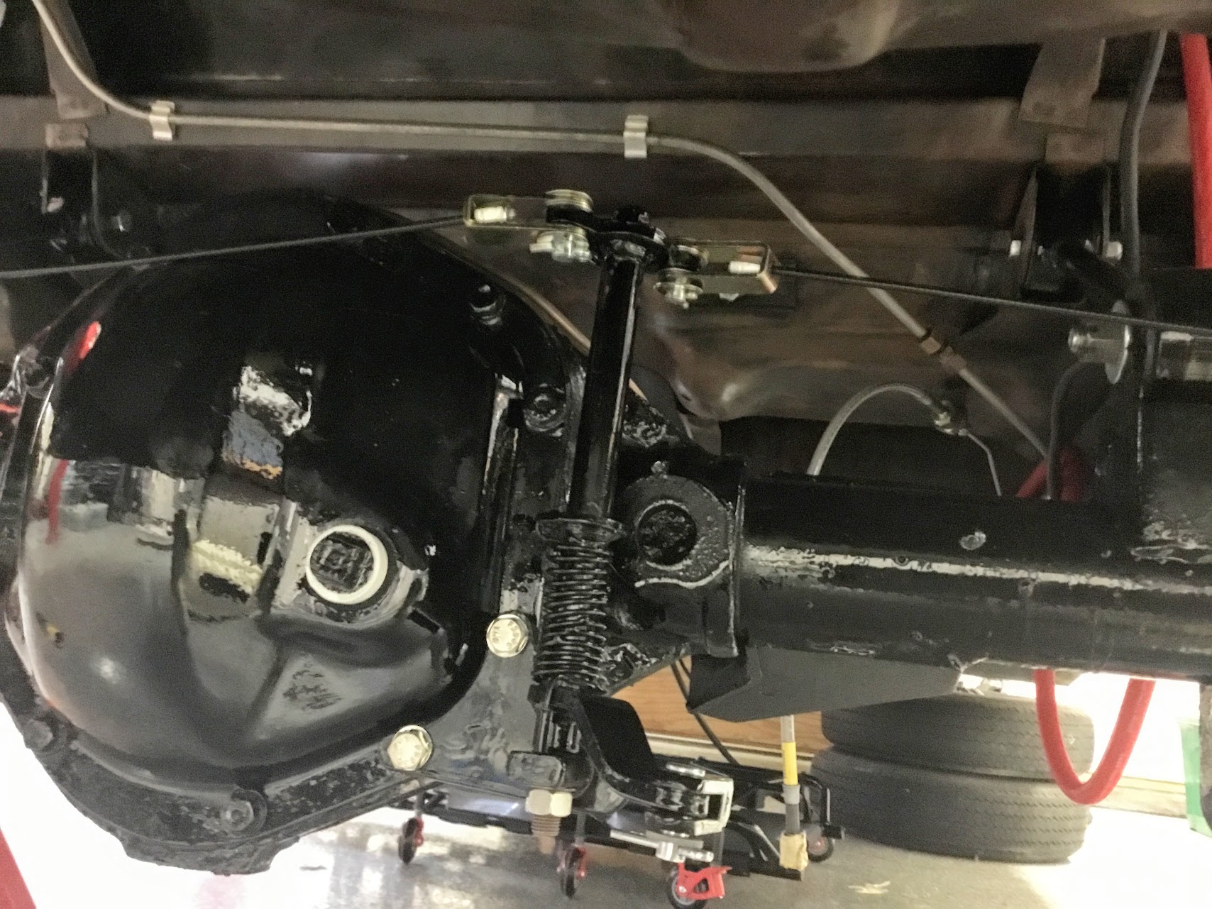
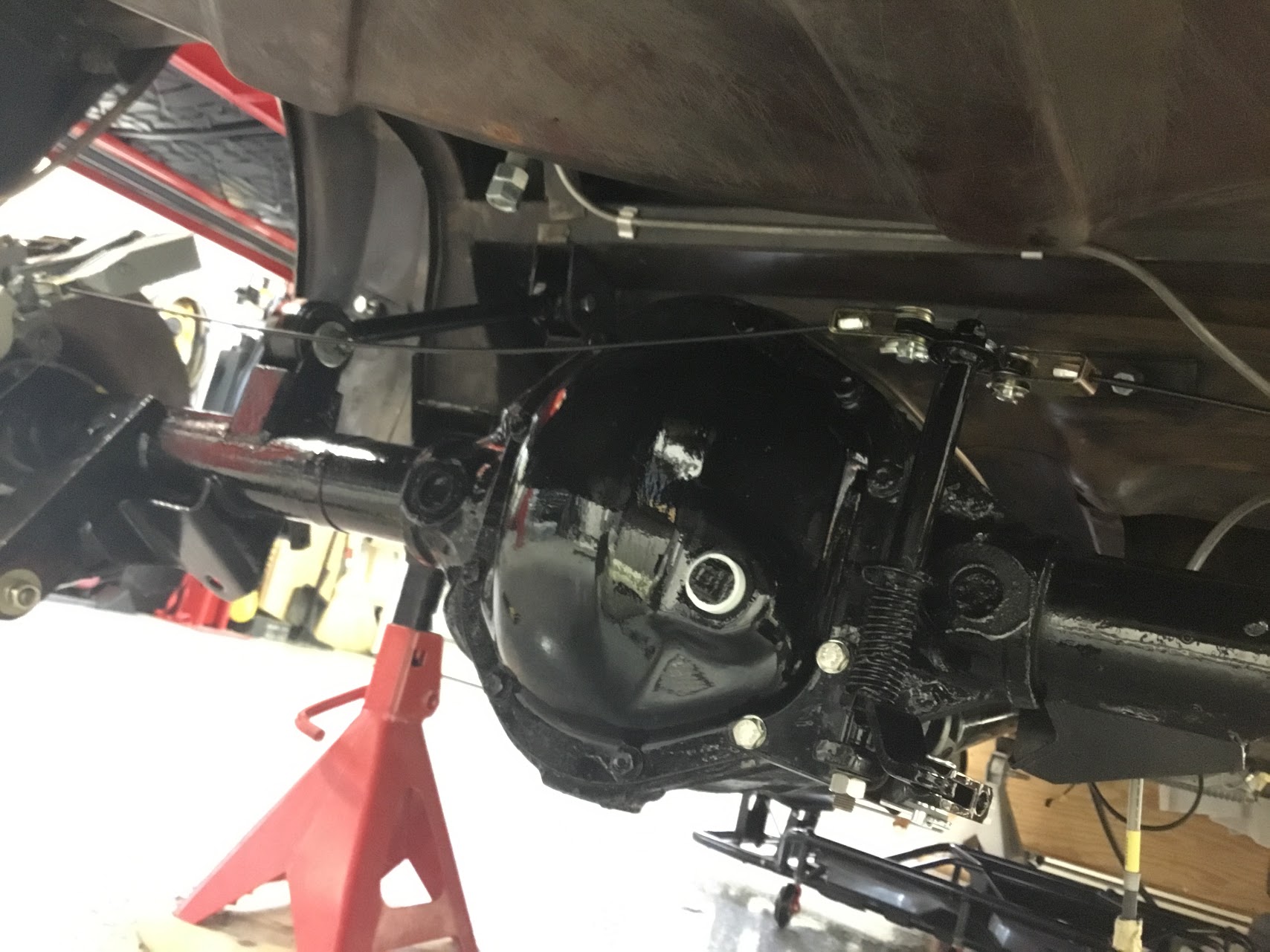
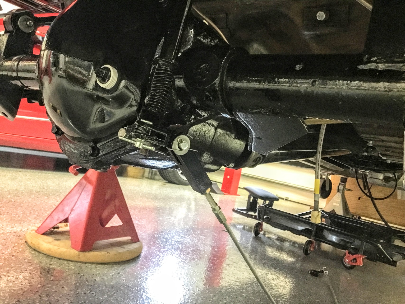
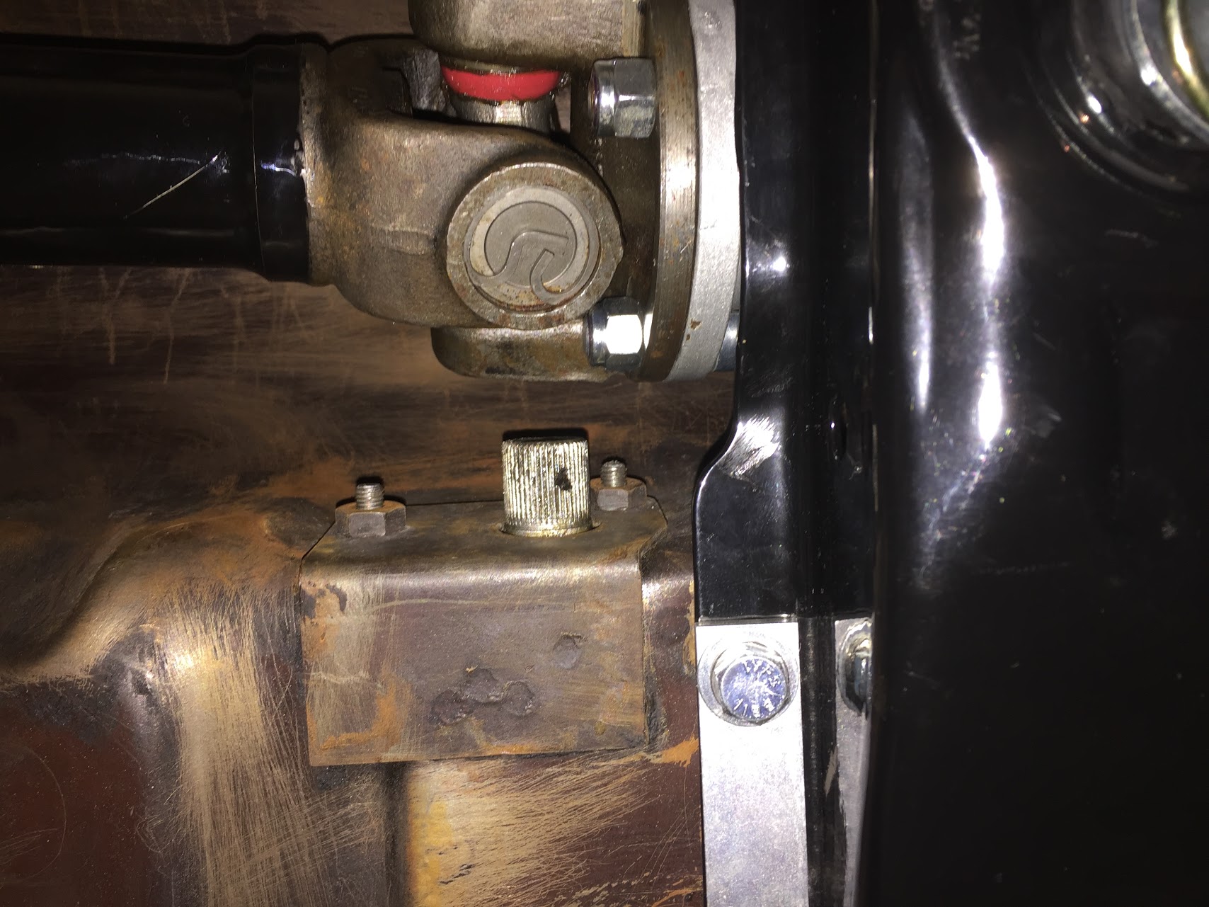
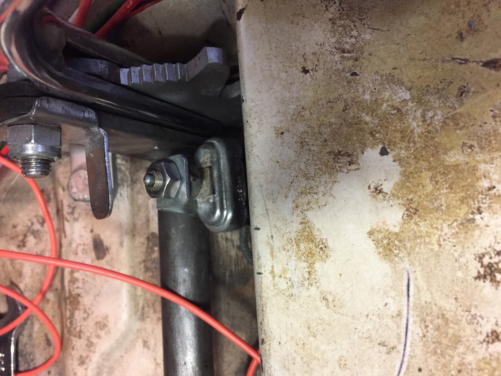
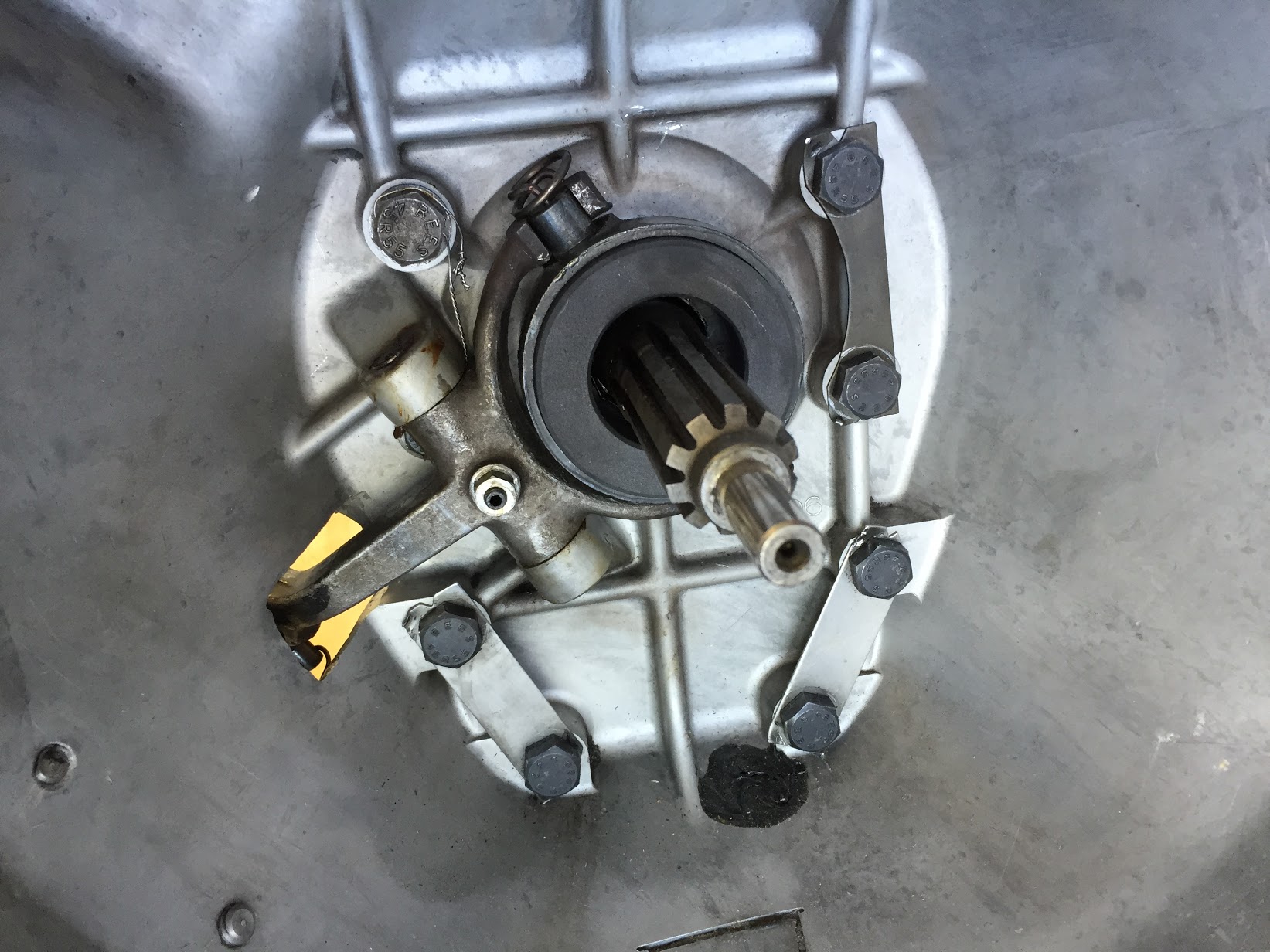
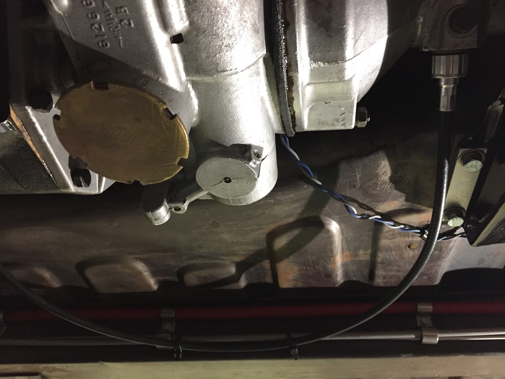
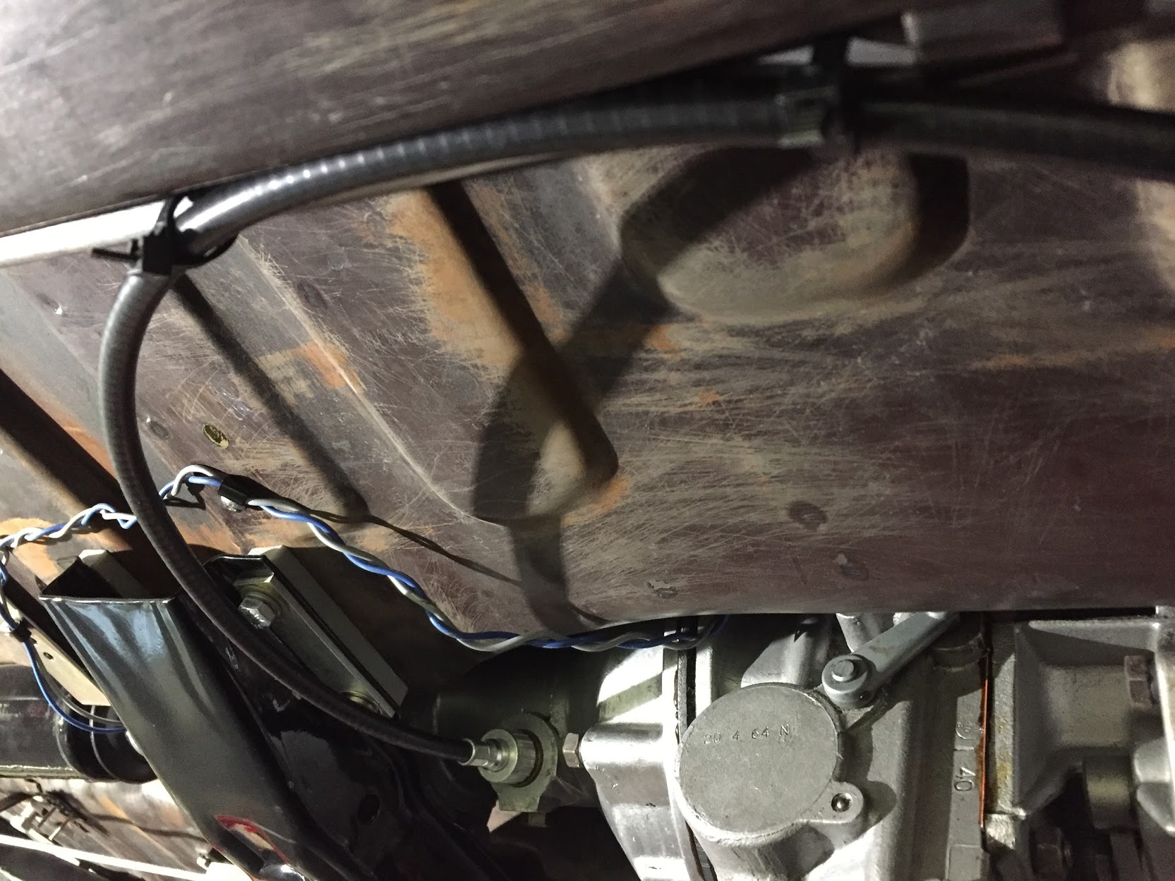
The electric overdrive is activated by a lever switch on the right side of the steering column. Power is derived from fuse position #14 of the CT fuse box. With lever activation a signal is sent to the overdrive interlock, or top gear switch located on the top of the gearbox and then to the overdrive solenoid. A warning indicator bulb is illuminated when the overdrive is engaged. More information about the switch and lever mechanism may be found in the “electrical components” post.
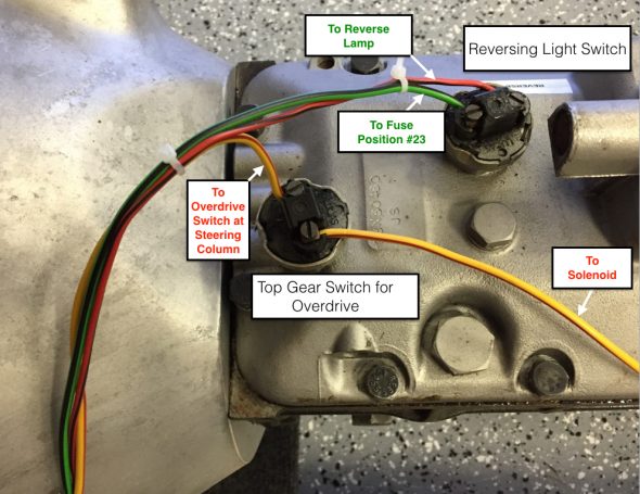
Overdrive Interlock or Top Gear Switch at gearbox
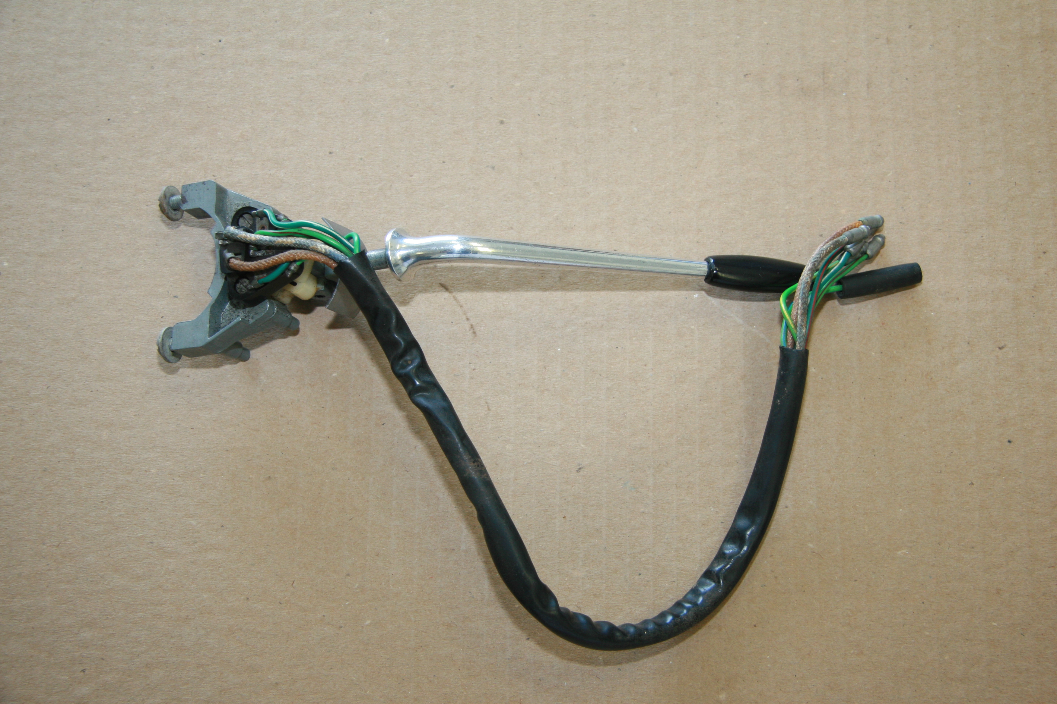
The lever on the left side of the steering column is used in an upward and downward motion to activate the LH and RH turn indicator flashers at the front and rear of the vehicle. When the flashers are functioning an indicator bulb located in a centralized position behind the steering wheel is illuminated in a flashing pattern. The headlamp flasher is activated by the driver pulling the same lever toward himself. This action will trigger the high beam warning light in the speedometer.
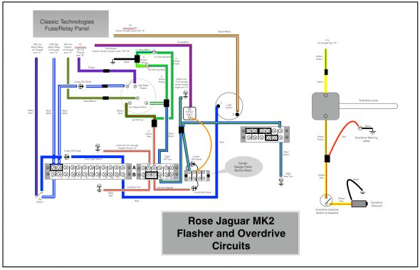
Rose Jaguar MK2 Flasher Circuit & Overdrive
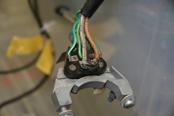
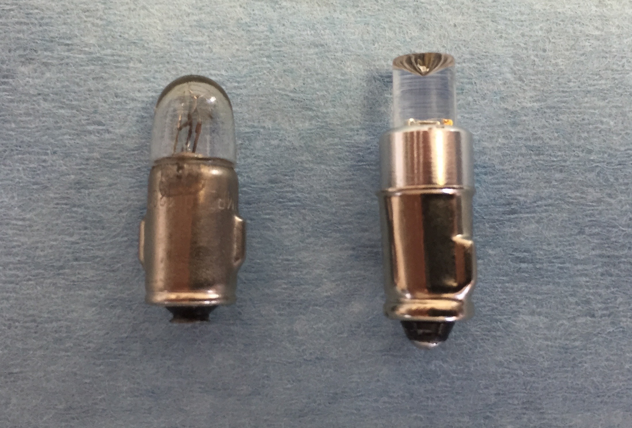
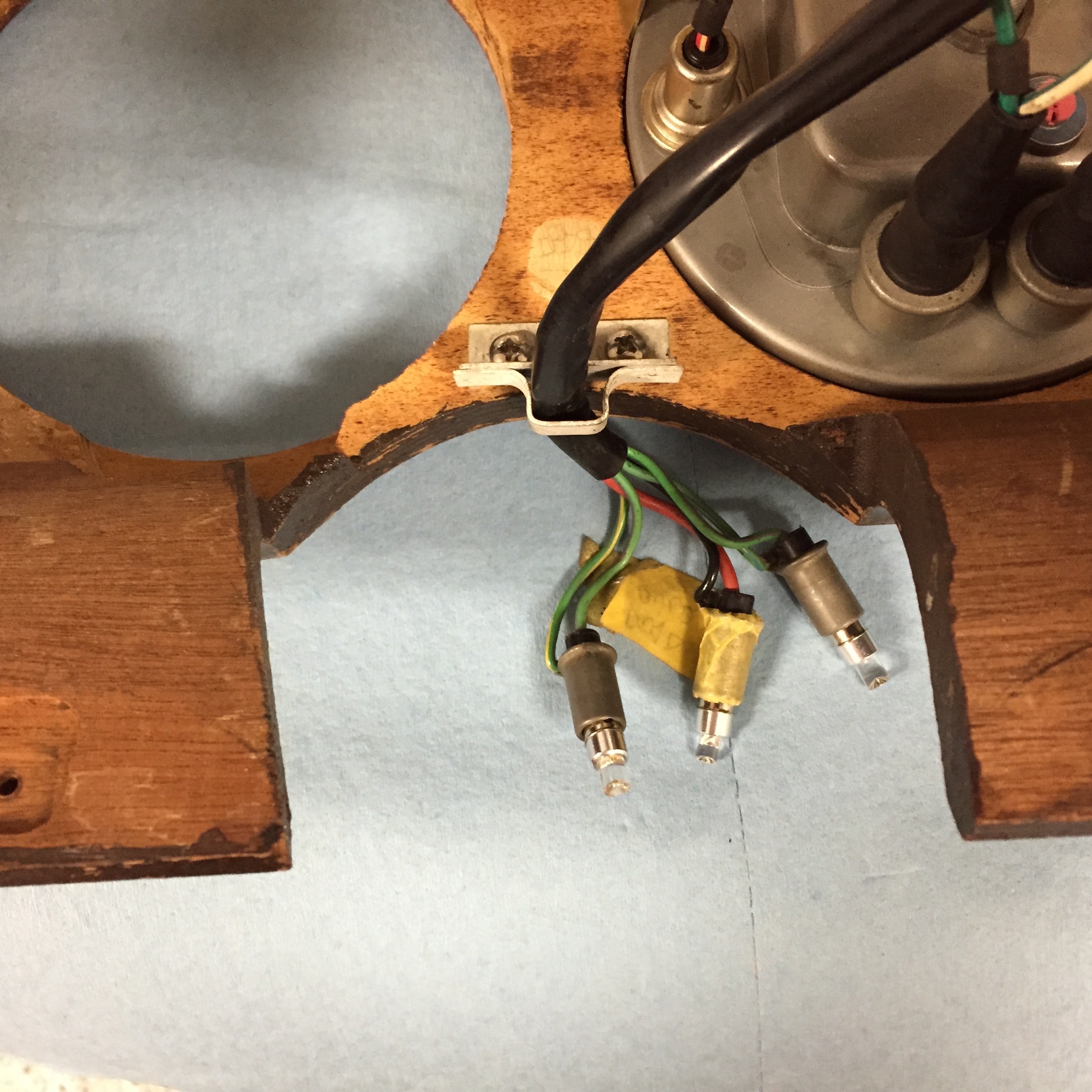
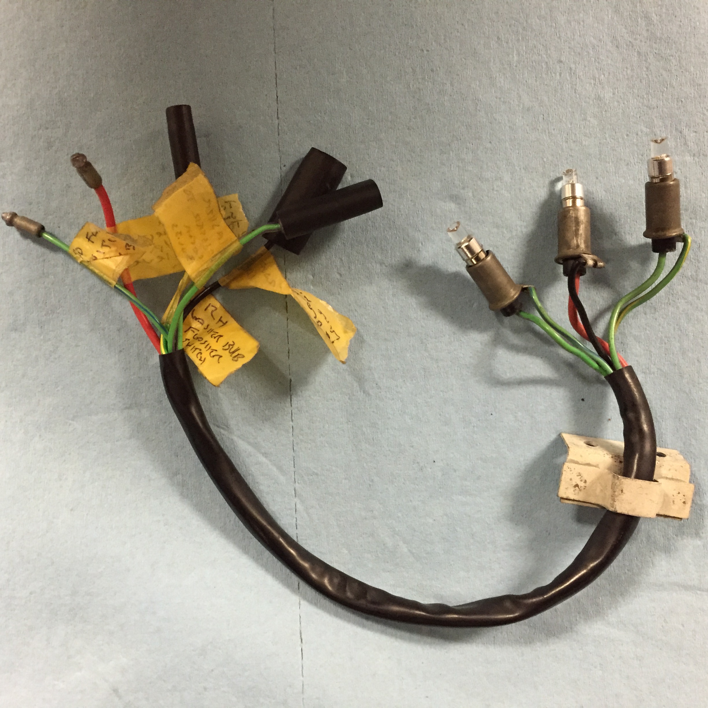
Turn Signal Switch Wiring
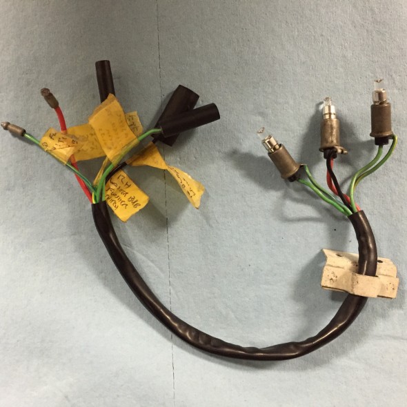
Turn Signal and overdrive indicator bulbs, holders, and pigtail
Auxiliary Power/USB Ports
I intend to install an arm rest/console between the front seats in my MK2. The console will include an auxiliary power/USB port unit. Power is sourced from the fuse box, position #12.
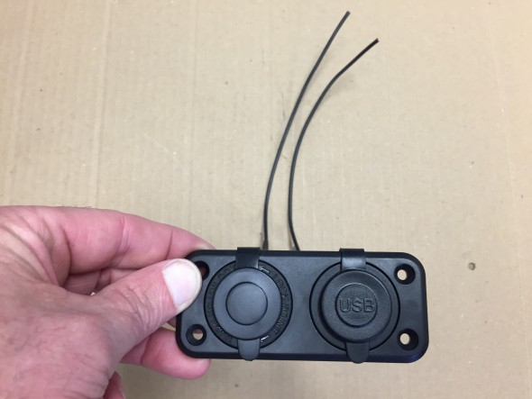
Auxiliary Power and USB unit
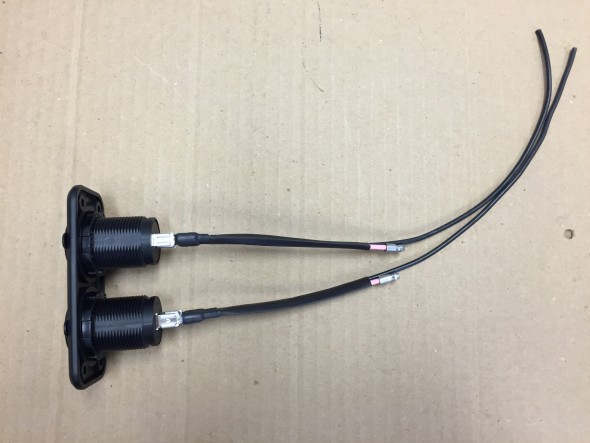
Auxiliary Power and USB unit
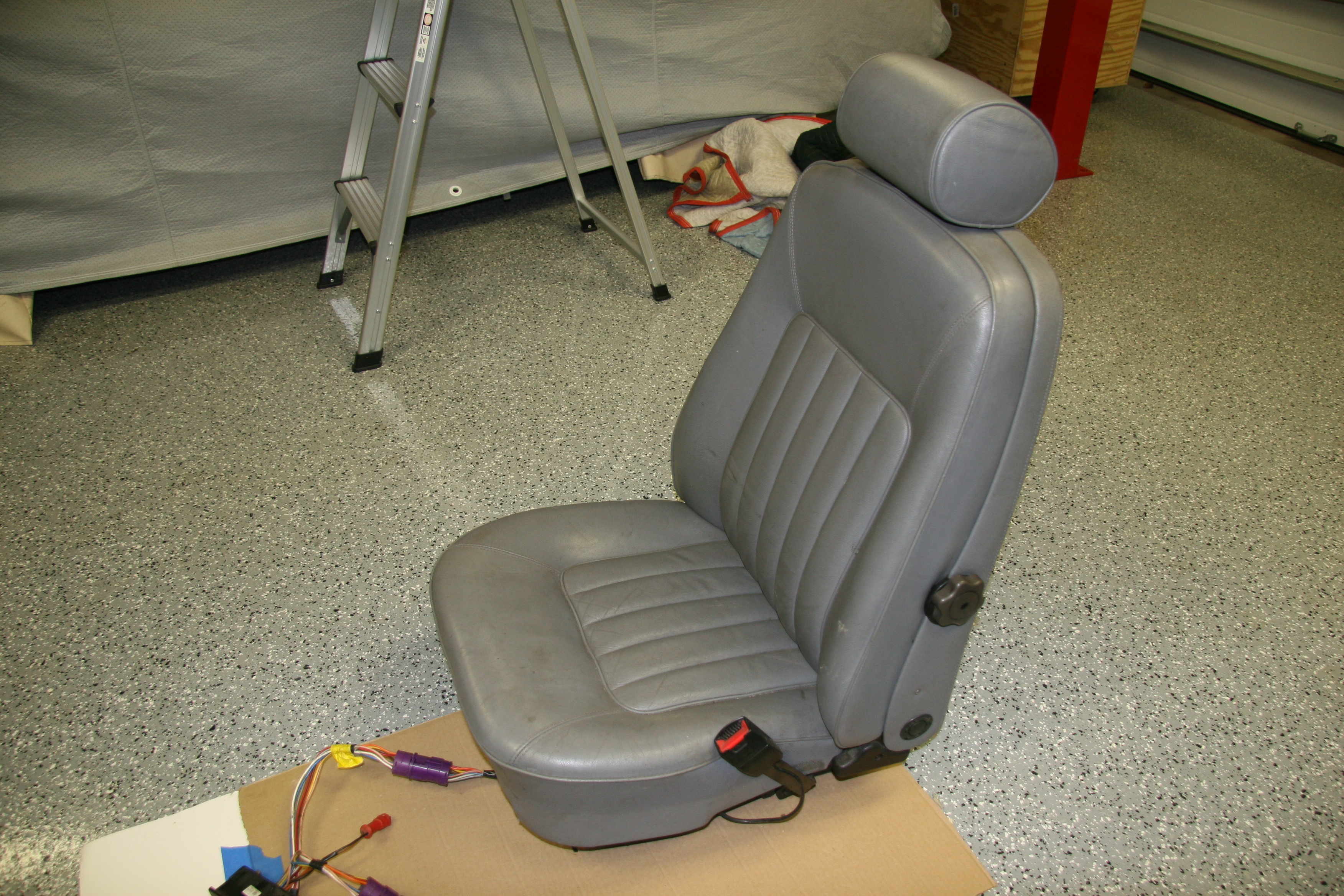
Powered Front Seats
The front seats I am using are from a Jaguar XJ40. More information about the seats is available at the “Seating” post. They have more features than I plan to use.
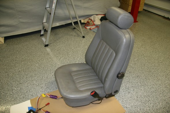
1990 Daimler Front Seats
Although the wiring harnesses were complete, there were a number of electrical connectors on the harnesses with no explanation as to what needed to be connected where to get the seats functioning.
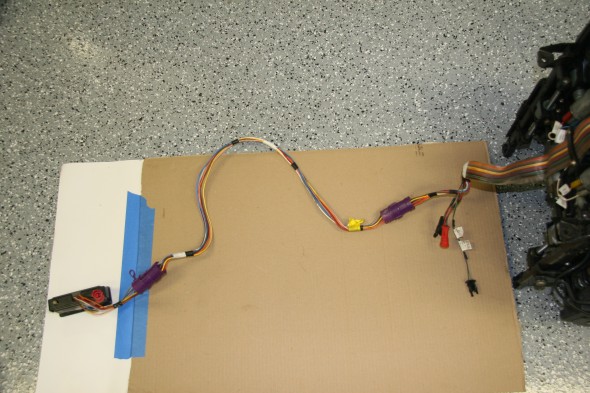
Seat Wiring Harness and Switches
The seats have seat heaters (upper and lower cushions), a memory feature for the driver’s seat, seat belt alarms, and wiring to permit automatic movement of the driver’s seat to the aft position when the driver’s door is opened.
After some enquiries on the Forums, Bryan Neish came to my aid. He was of great help figuring out what the wiring at each of the connectors did. I know he spent quite a lot of time reviewing wiring diagrams to find what I needed. George Leicht was also helpful. He sent along the wiring diagram that accurately reflected my seat wiring.
I wired the seats to unswitched power at the fuse box to facilitate seat operation before entry or before starting the ignition. I was able to use the original seat wiring harness and bank of switches to control the four motors adjusting the lower and upper seat cushions for each chair. The wiring runs under the center console to each seat. A pdf file of the seat wiring schematic for 1990 may be found here: 1990 Jaguar XJ40 Seat Electrical Schematic
I have yet to decide where I will mount the switches. The image below shows the approximate location of the switches as Ton Tulleken installed them on his car:
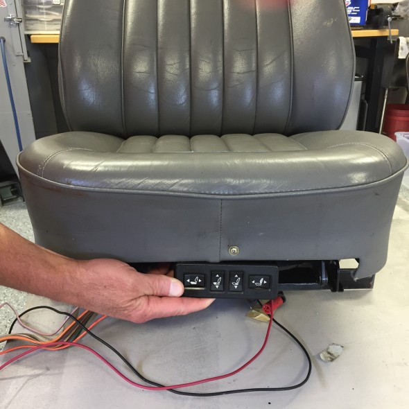
Possible Placement of Seat Switches
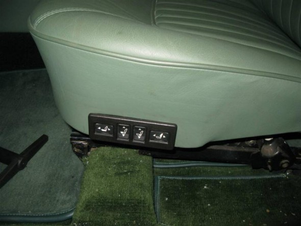
Kevin Moore’s MK2 power seat switches
The image above shows the location of the switches in Kevin Moore’s car.
Lighting
SideLights
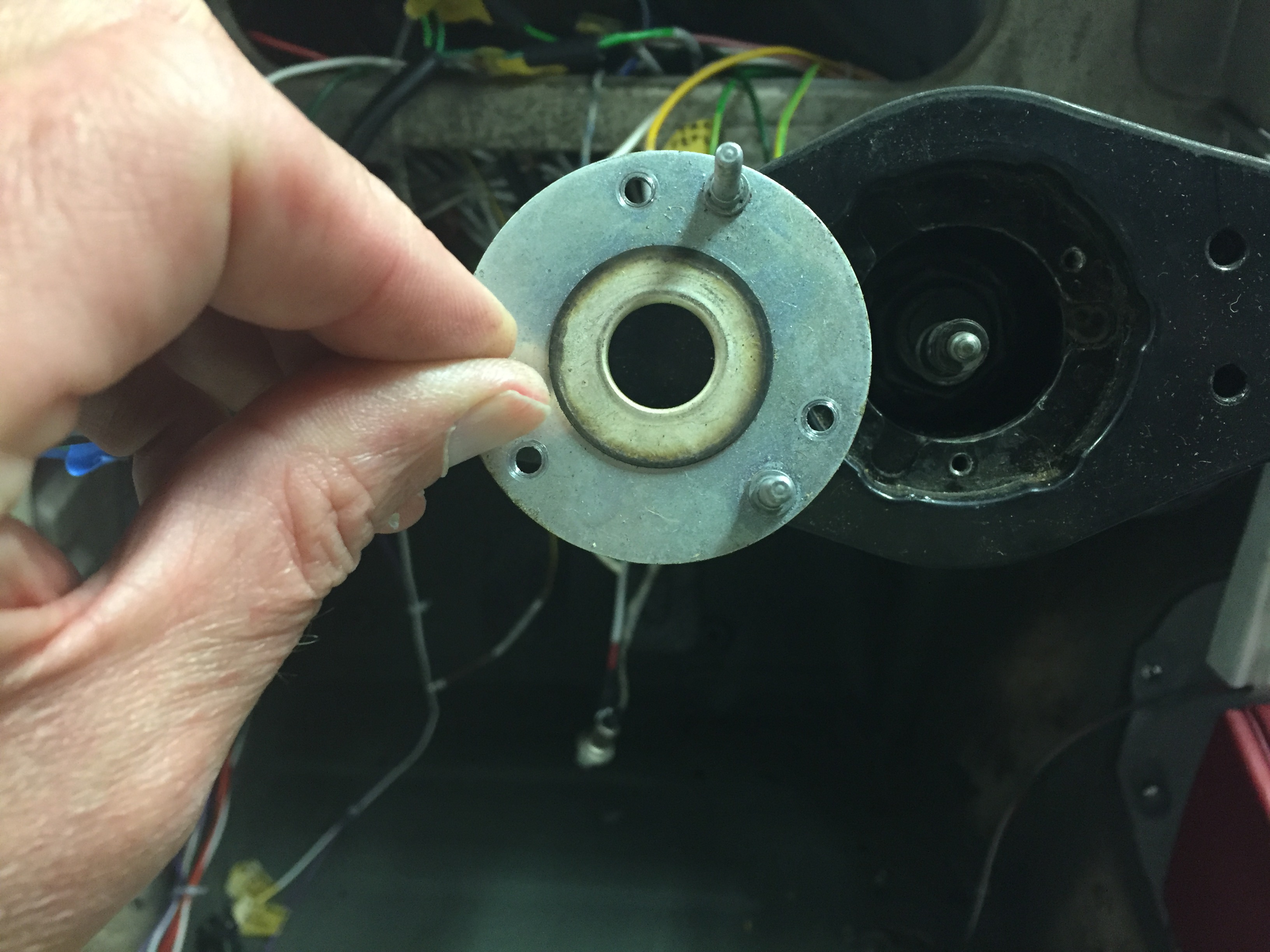
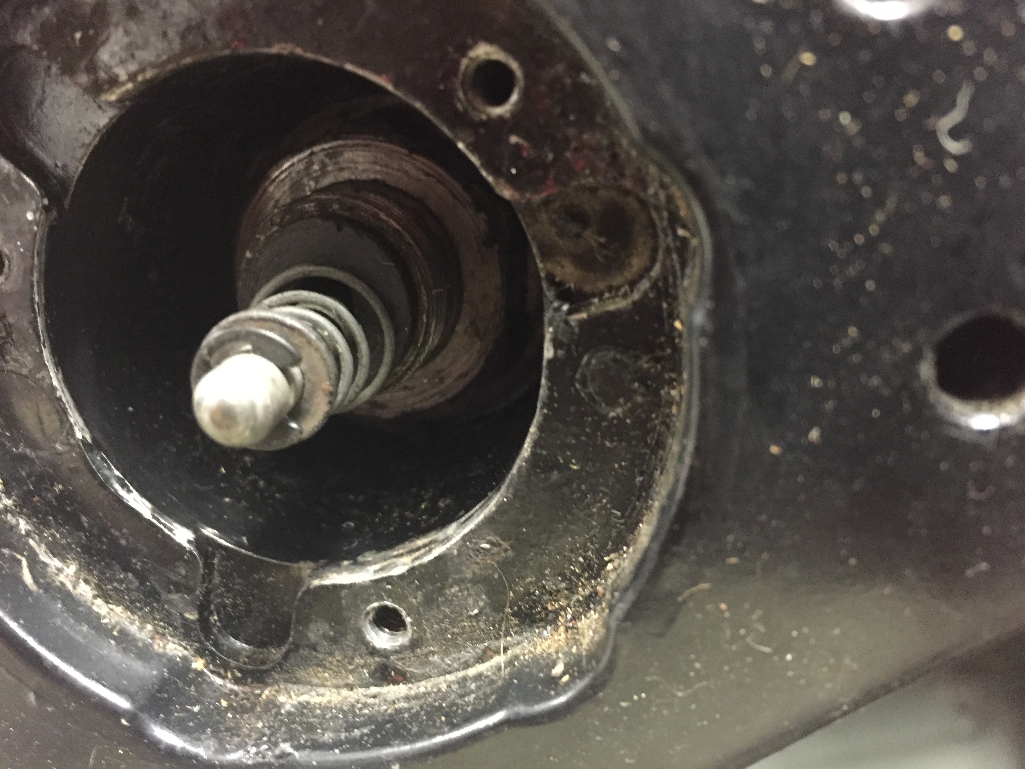
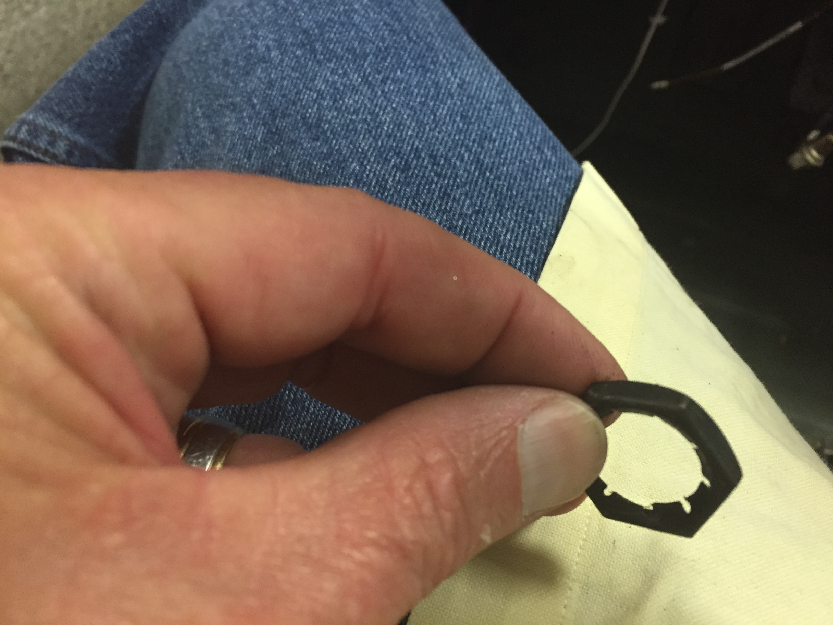
Additional detail about the sidelamps may be seen in the exterior lighting post. I rewired the original side lamp fixtures and trial fitted them to the body. The rubber “O” rings supplied by SNG Barratt are to thick to fit properly so I replaced them with metric 24mm – 2mm “O”rings ordered from McMaster Carr. New LED bulbs were also fitted in the fixtures. The red 18 AWG wire from the bulb is combined with a black 14 AWG ground wire from the fixture in a vinyl sleeve that goes through the LH and RH valance lighting grommet.
SideLamps
RH Side Lamp Wiring & Sleeving
Refurbished side lights installed
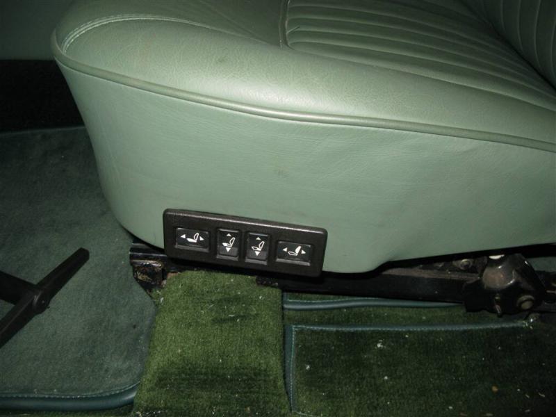
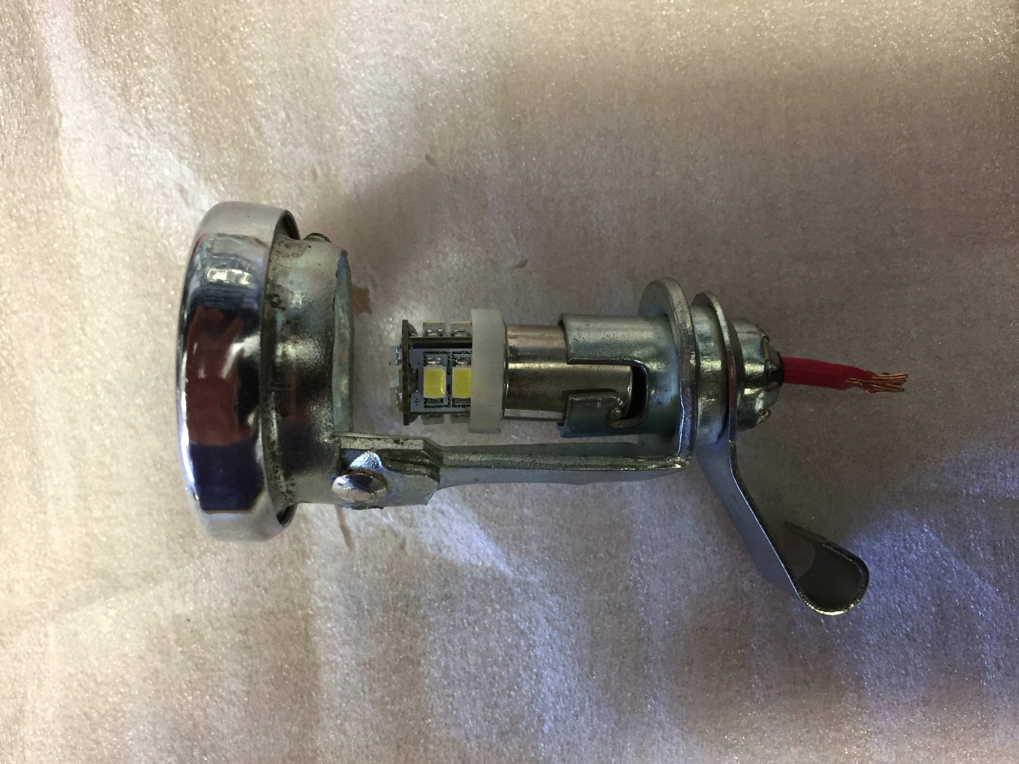
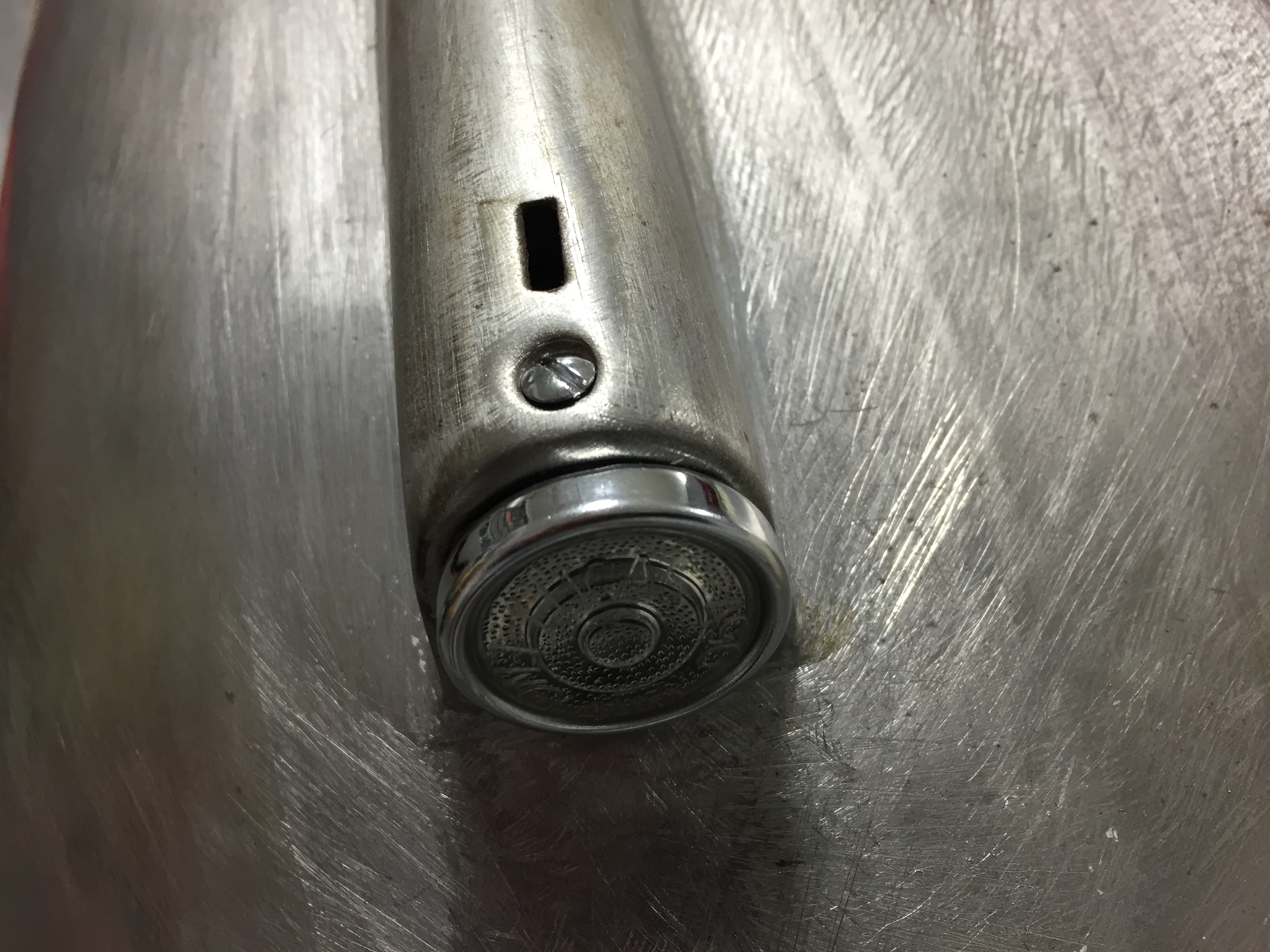
Turn Signal Flasher Lamps
After installing the side lamps I moved to the turn signal flashers. Information about the lamps is contained in the exterior lights post. I re-used the original fixture wire terminals but replaced the power and ground wiring with new. The power wire is blue/green 18 AWG and the ground wire is black 14AWG. The wiring is pushed through holes on the back end of the fixture’s new rubber boot. New vinyl sleeving was also used for the flasher lamps.

Front Flasher Turn signal

Turn Signal Flasher with LED Installed
Turn Signal Flasher Wiring
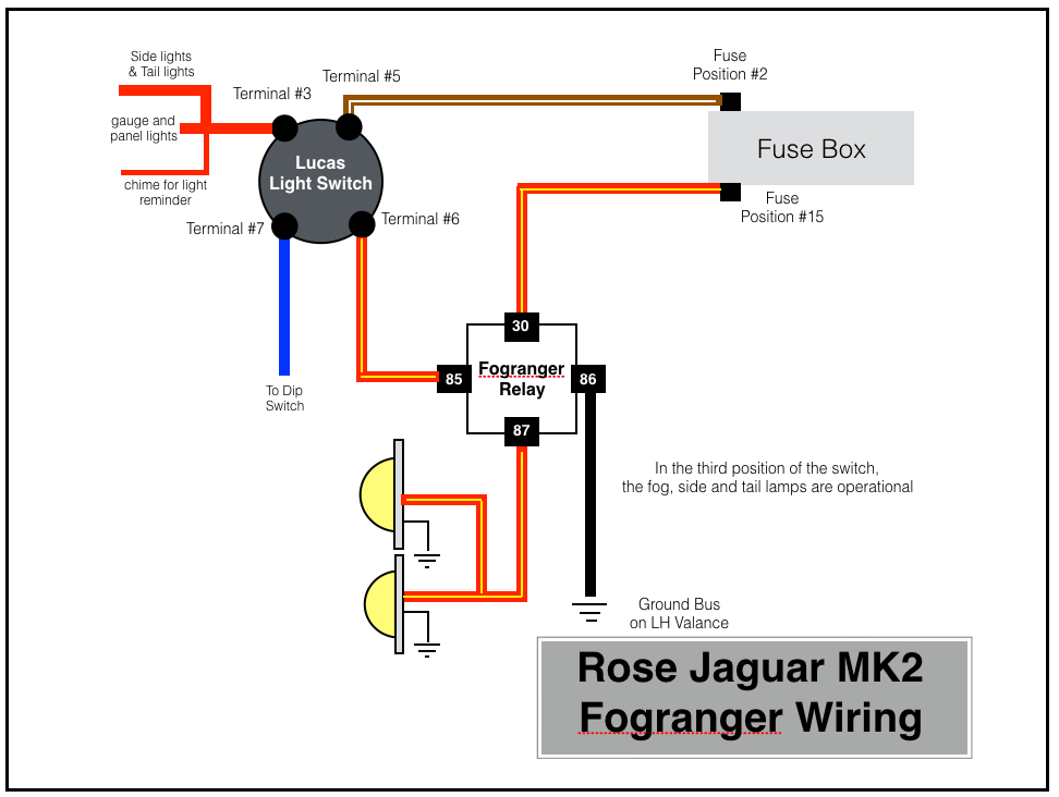
Fograngers
More information about the fog rangers may be found in the exterior lights post. The Classic Technologies Fuse box did not have a relay designed into the product for fog or driving lights, so I added a Bosch relay for this function. It is mounted on the original fuse panel in the engine bay on the LH valance. The foglights are controlled by the primary light switch.
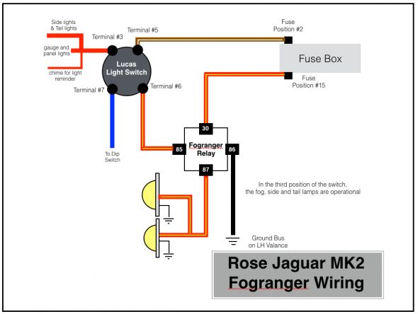
Rose Jaguar MK2 Fogranger Wiring

Fogranger Relay
RH Fogranger Installed
Headlights
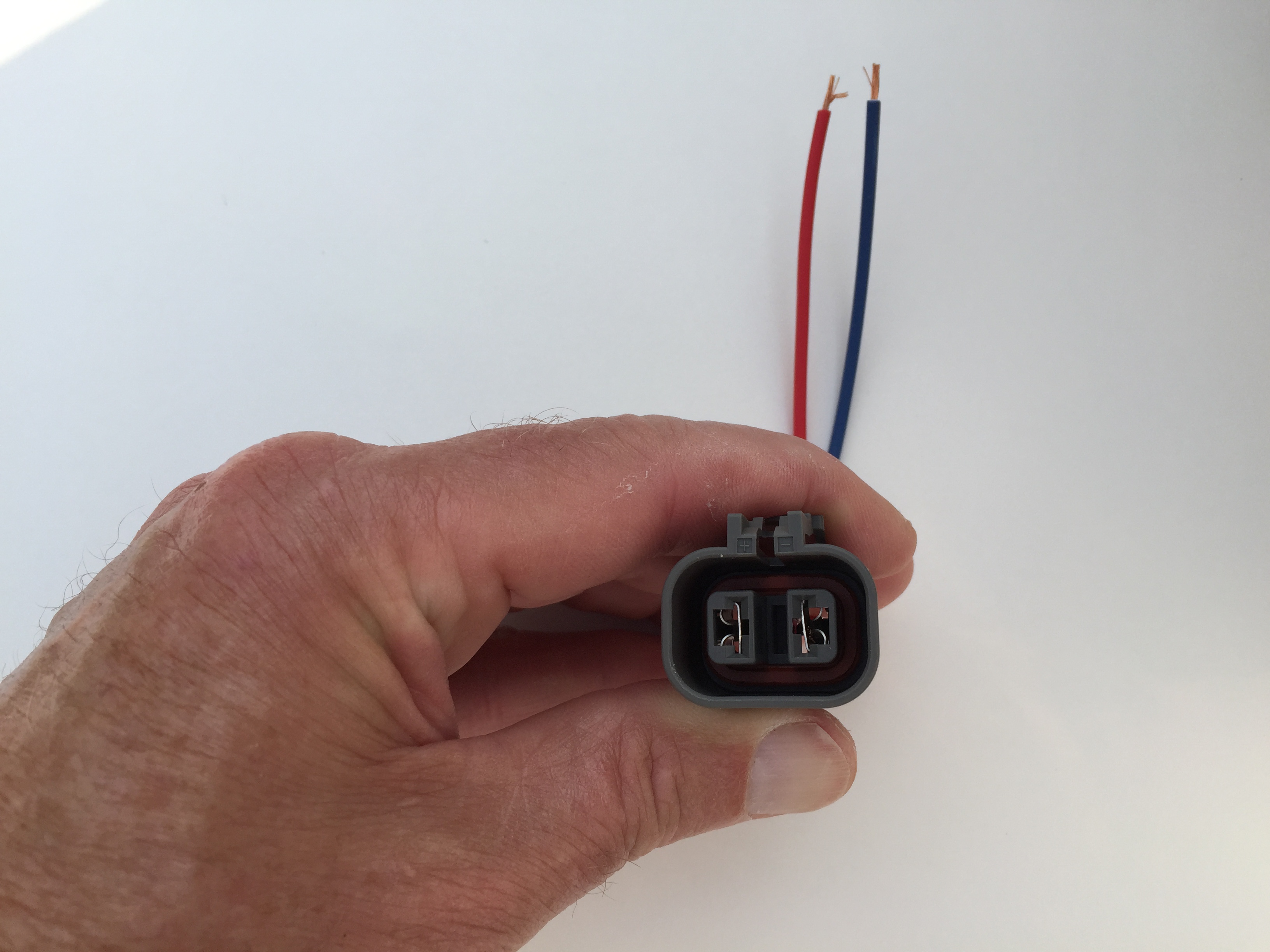
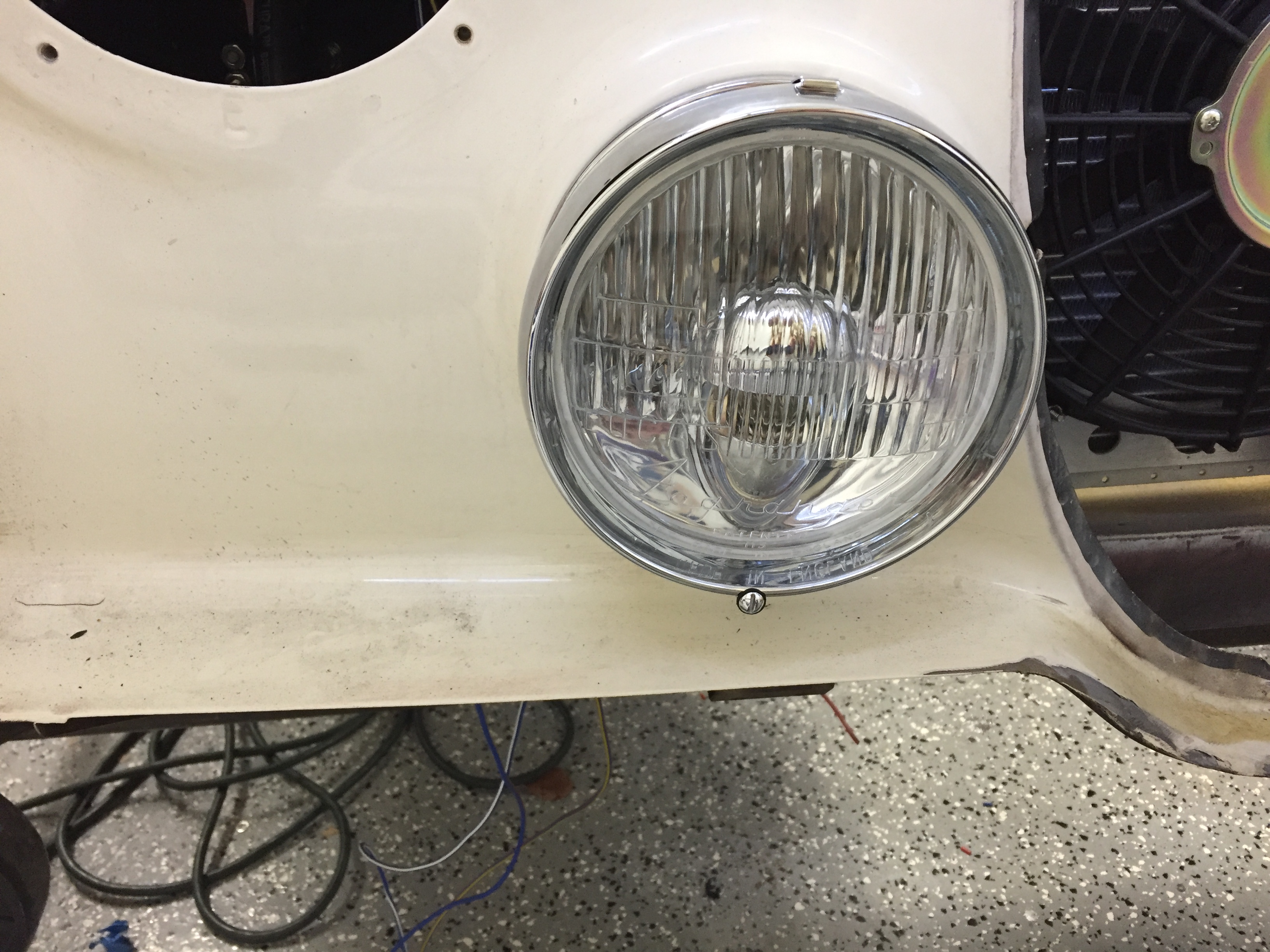
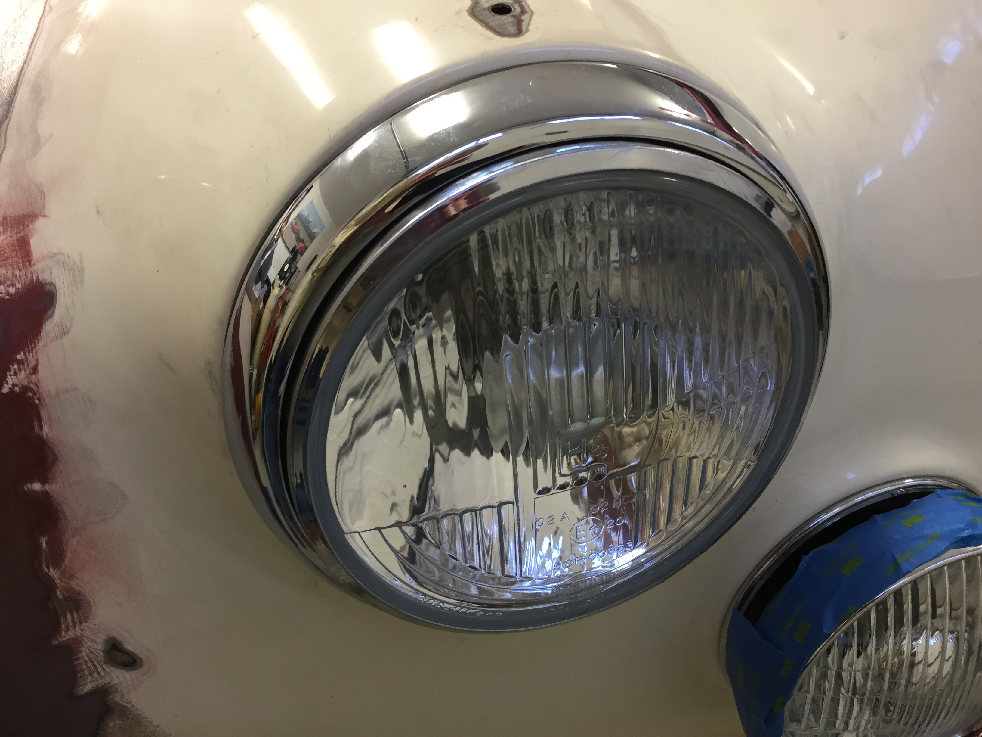
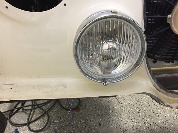
More information about the headlights may be found in the exterior lights post. I installed new 3 wire (high beam, low beam, and ground) plugs, wiring and sleeving for the headlights.

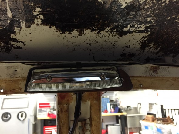
Headlight Installed with Newly Chromed Trim Ring
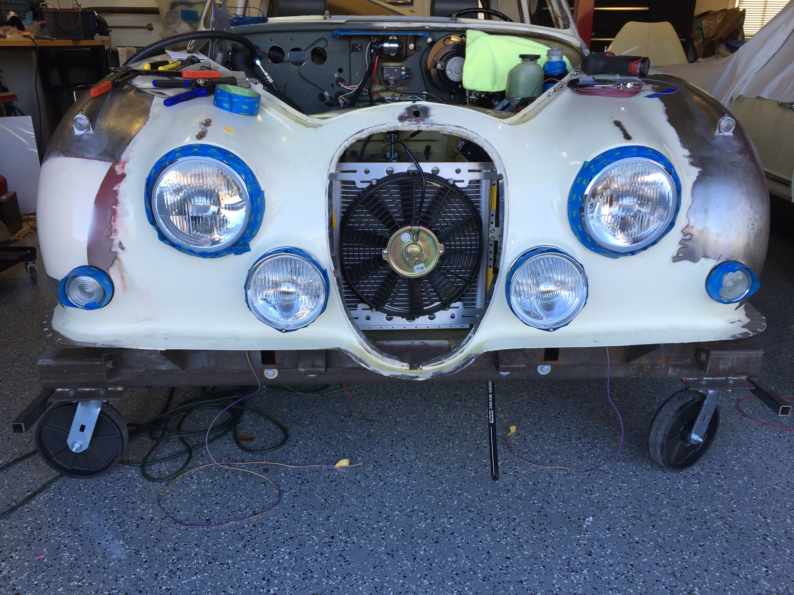
Although not too pretty yet, this image shows the temporary installation of all of the front exterior lights. The blue painter’s tape is to protect the chrome. The installation was done to make sure that I had all the parts needed for a particular light and to test the electric circuitry and switches.
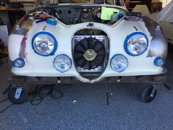
Temporary Installation of front Exterior Lights
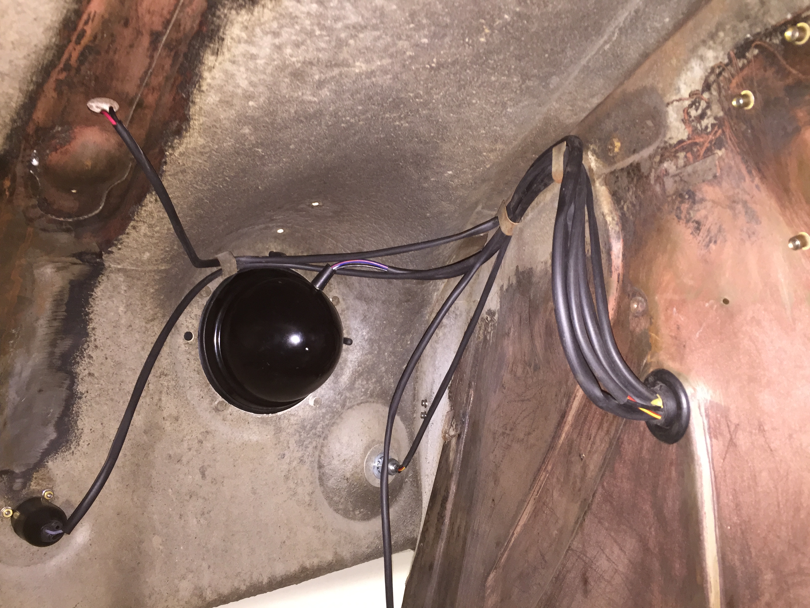
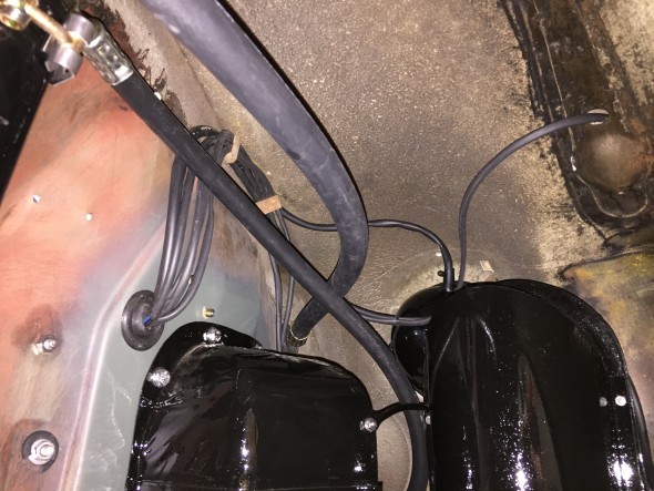
These images show the exterior lights wiring in new sleeving as it is routed from the individual fixture through the large wiring grommet located on each valance.
LH Front Exterior Lights Wire Sleeving and Routing
Tail Lights
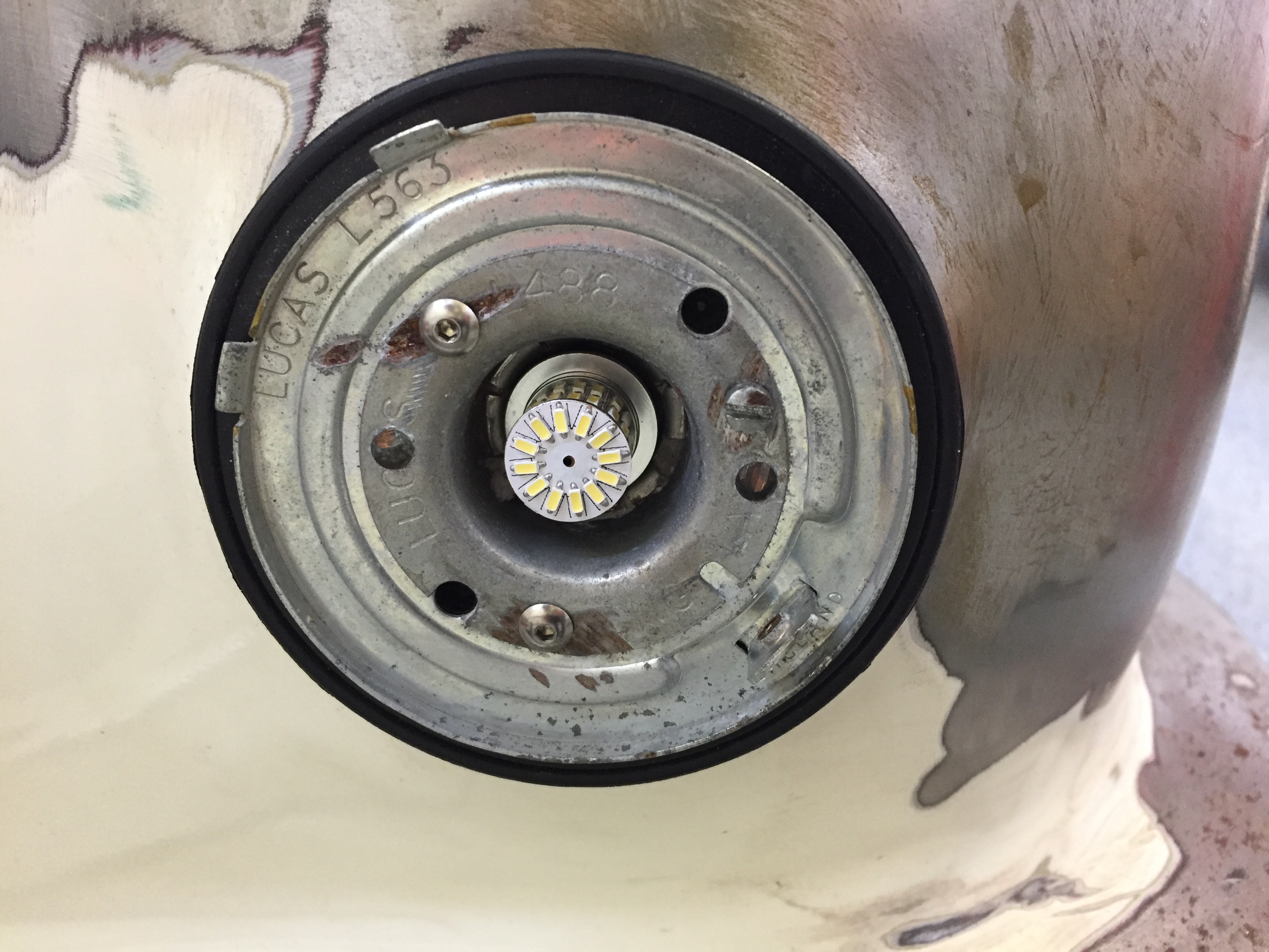
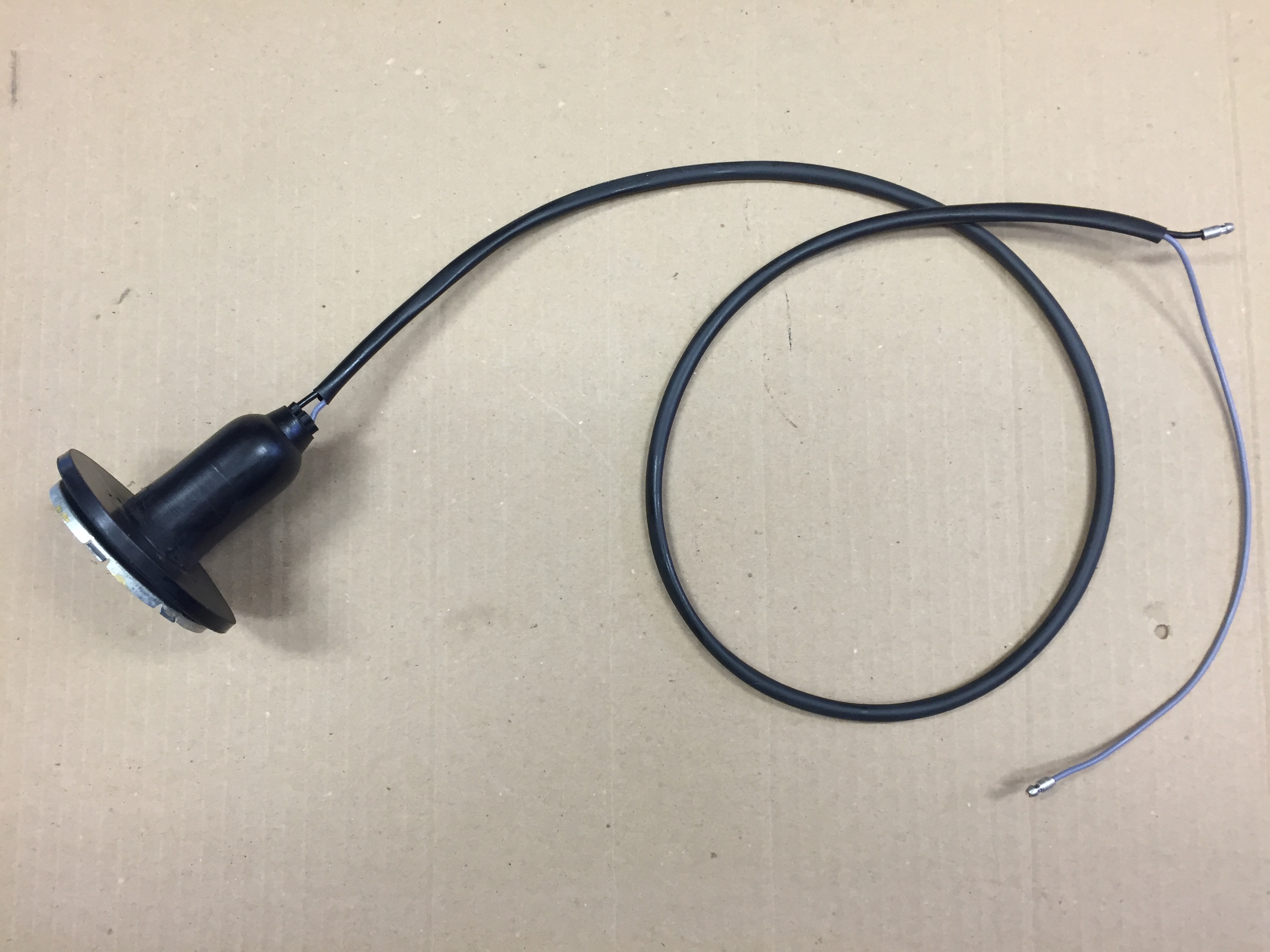
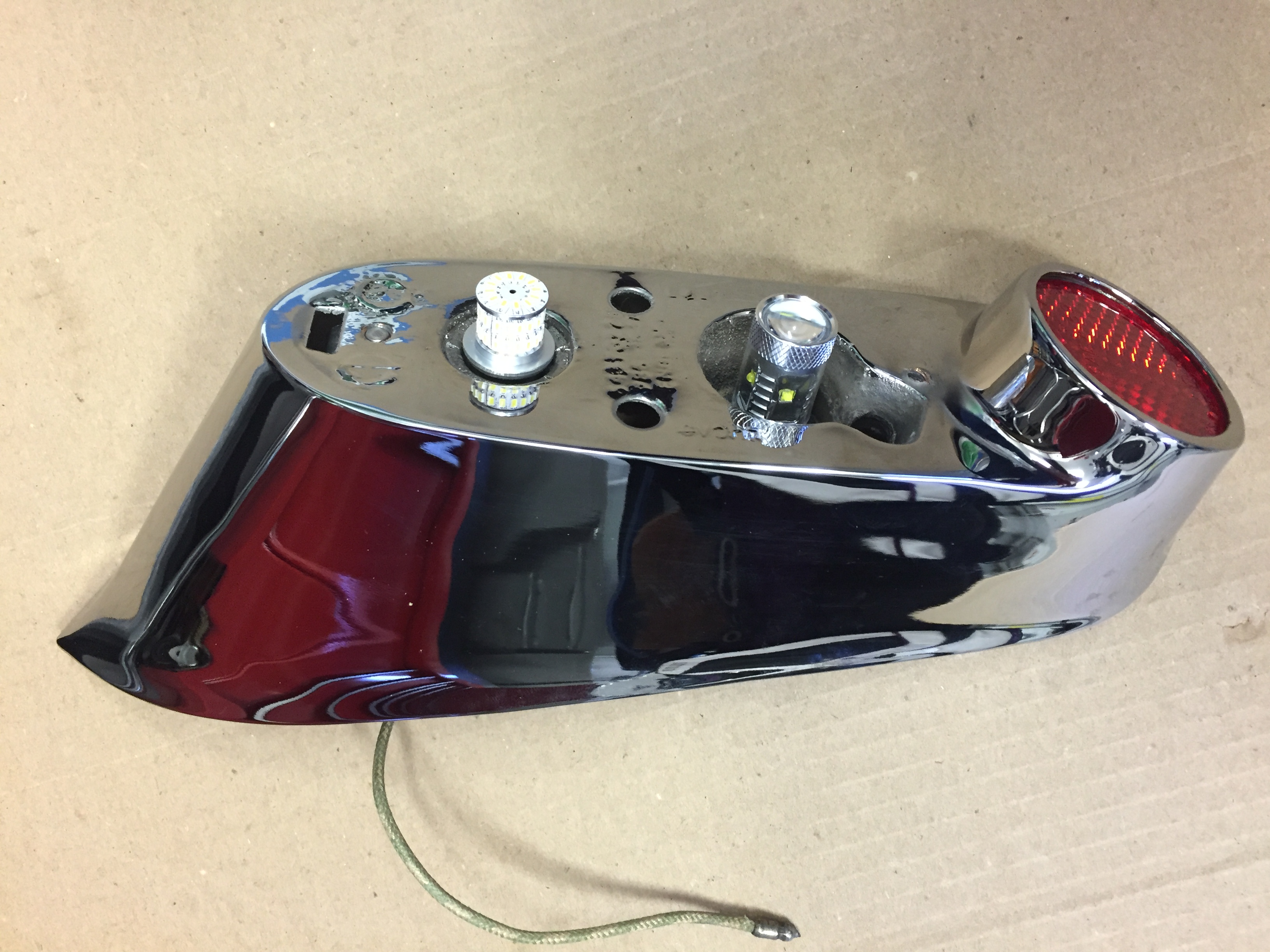
More information about the tail lights may be found in the exterior lights post. I substituted LED bulbs for the original incandescent type; however, the wiring remains the same. In fact, I was able to reuse the original wire leads from each of the bulb holders. The upper bulb is for the flasher with a single wire lead. The lower bulb is for the regular lights plus an additional light for the brakes with a double wire lead.
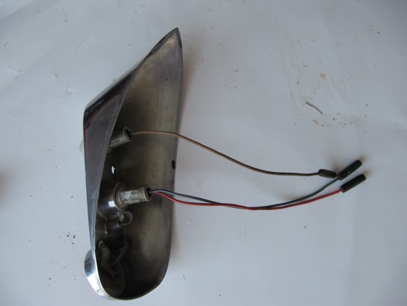
Tail Light Wire Leads

Tail Light LED Bulbs
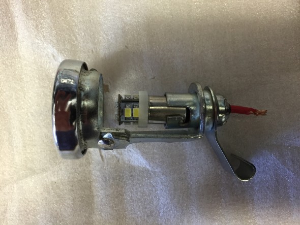
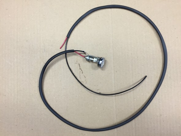
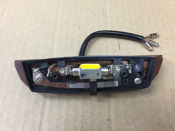
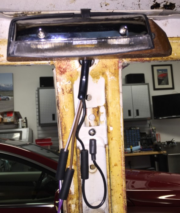
Number plate illumination and reverse lamp
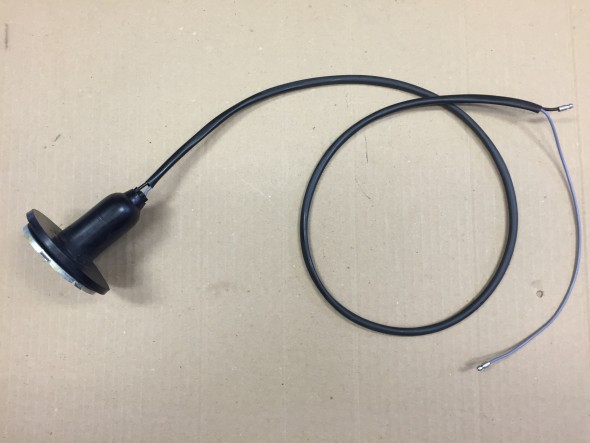
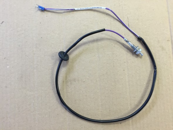
More information about the lamp may be found in the exterior lights post. The lamp includes one light for the luggage compartment, two bulbs for the license plate illumination, and one bulb for reversing. All original incandescent bulbs were replaced with LEDs. The original wiring harness for the lamp was in pretty good shape, but I constructed a new one with all fresh wiring.
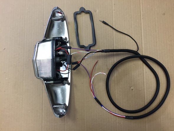
Boot Lamp with new wiring harness
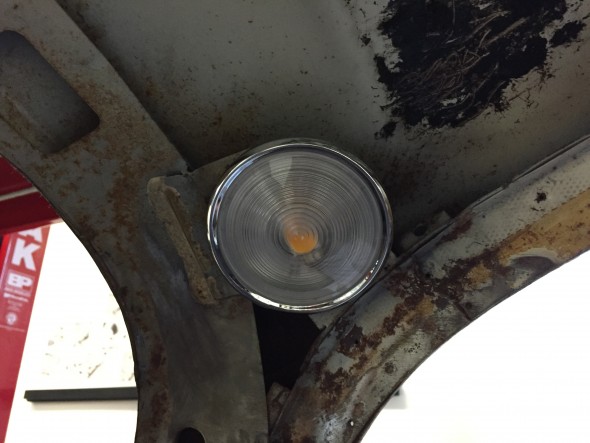
Luggage compartment lamp
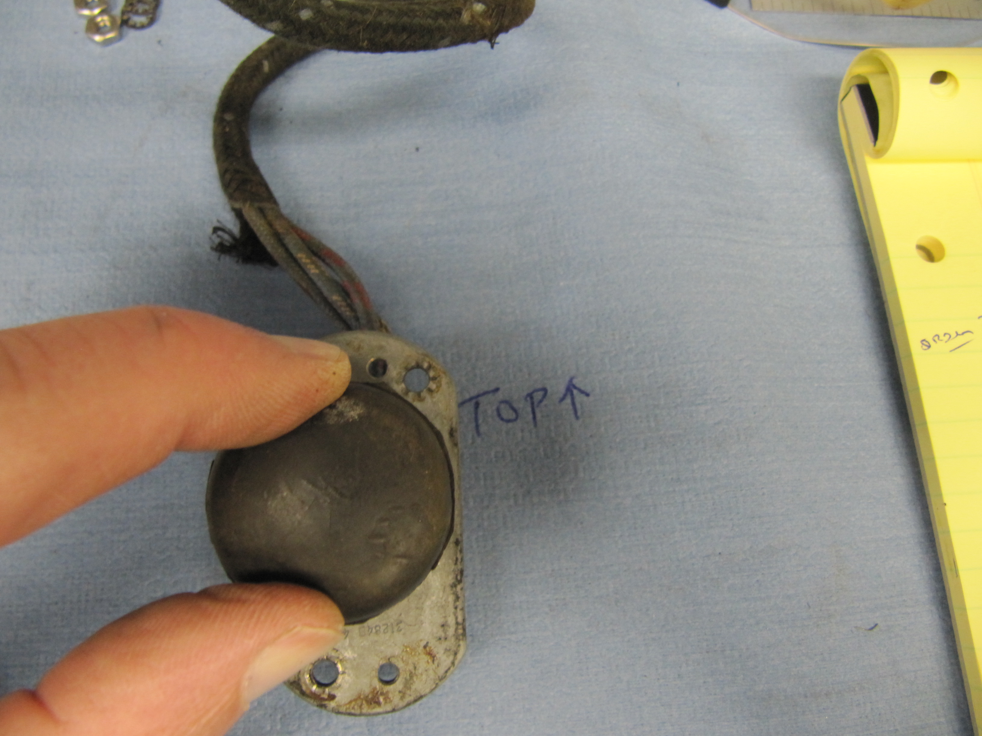
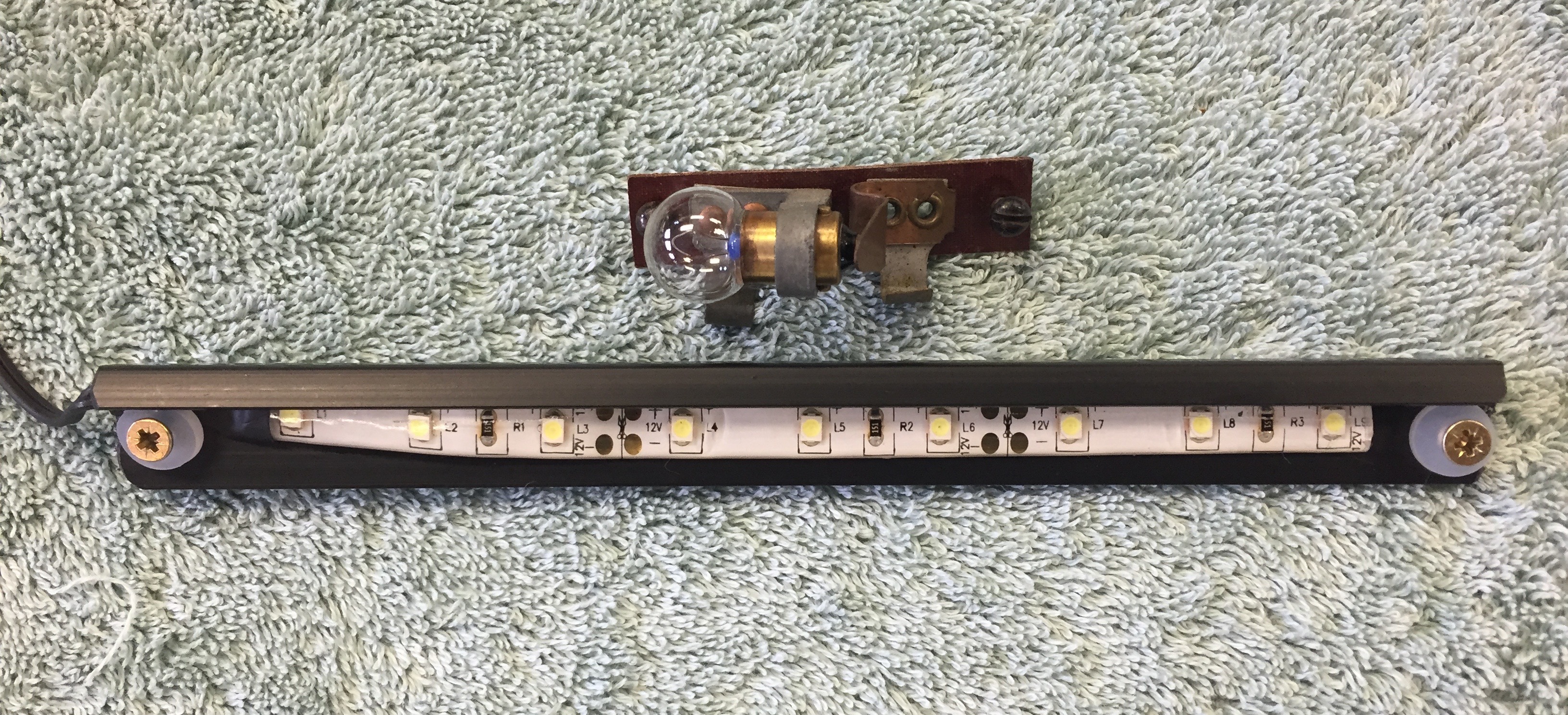
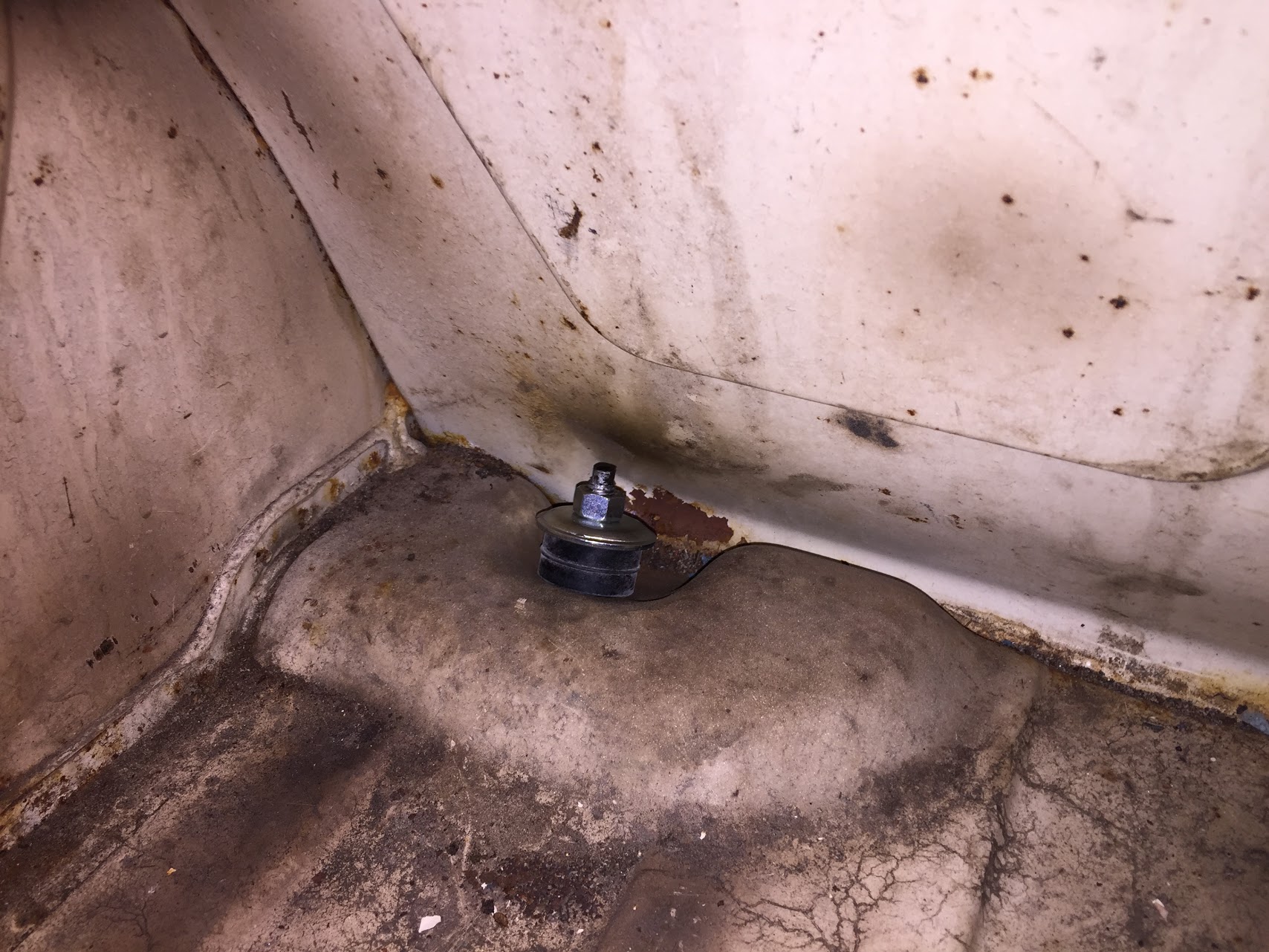
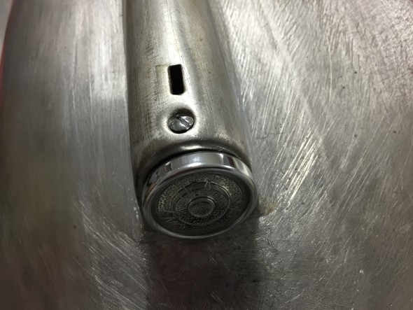
As my friend Eric Kriss points out in his MK2 restoration blog, the luggage lamp seemed to be an afterthought to Jaguar engineers. To function the light switch on the gauge panel had to be turned on, but it is often the case that one would want to access the luggage area after the car’s ignition, much less its lights were turned off! Instead of wiring the luggage compartment lamp in series with the front marker and rear tail lights, Eric revised the wiring to move the luggage compartment lamp to its own circuit. To make the lamp illuminate when the boot lid is opened a position sensitive mercury tilt switch is used. As Eric describes, when upright a ground connection is established permitting current to flow to the bulb. When the boot lid is shut, the ground connection is broken so the light goes off.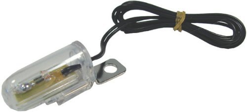
Interior Lights
The MK2 as original had six interior lamps: the map light at the central gauge panel, a lamp at the top of each center or “B/C” pillar, a lamp in the cubby box and a lamp on each side of the rear of the car above the passenger seat. These latter lamps referred to as rear quarter interior lamps. My Mk2 will also have two courtesy lamps in the back of the front seat headrests. More information concerning these lamps may be found at the “Interior Lights” post.
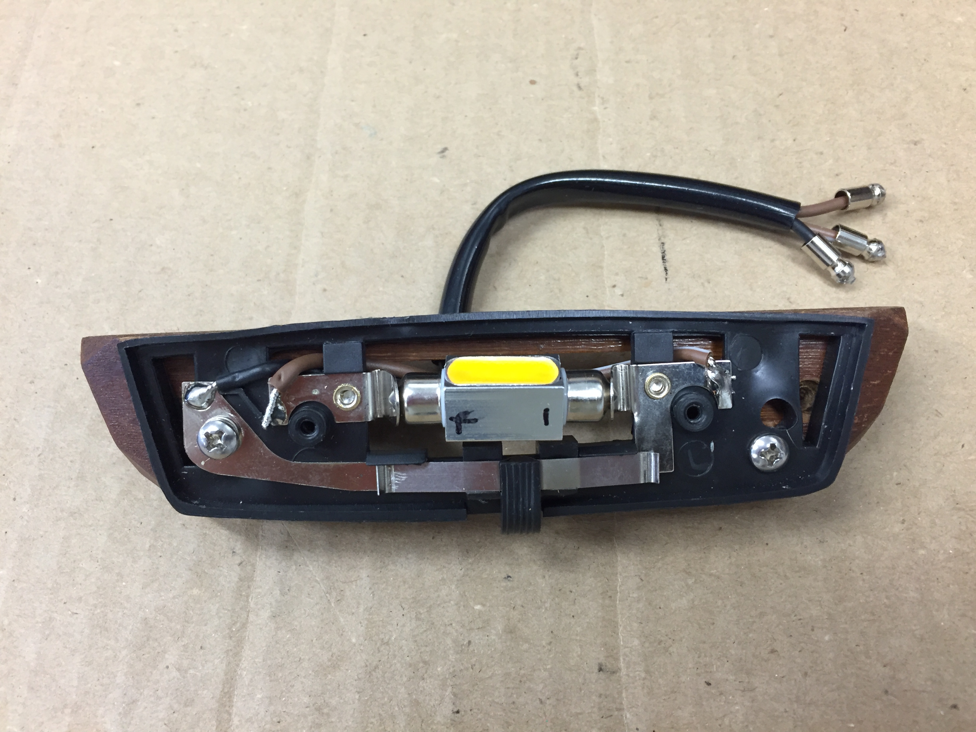
As pointed out in the “Interior Lights” post, the replacement center pillar lamps are not exact replacements for the originals. They are operationally superior in that they provide an “on-off” switch at the lamp, and also because they screw, rather than snap, together. They just don’t look quite as nice being plastic rather than chrome metal. Just to check fit and to test the electrical system I did install the new center pillar lamps mounted on their wood bases. An additional grounding wire is used with the new lamp for its switch so there are three wires rather than the original two. For purposes of testing the electric system I temporarily fixed the third ground wire to the pillar as shown in the third photo below.
36 mm festoon bulbs in warm white were substituted for the original incandescent bulbs.The lamps are wired to the interior lighting circuit that includes the interior lamps toggle switch on the central gauge panel as well as the four door switches. The black ground wire is simply attached to the metal center pillar.
New three-wire center pillar lamp with switch
New center pillar lamp loosely mounted on wood base
Temporary ground connection for center pillar lamp switch
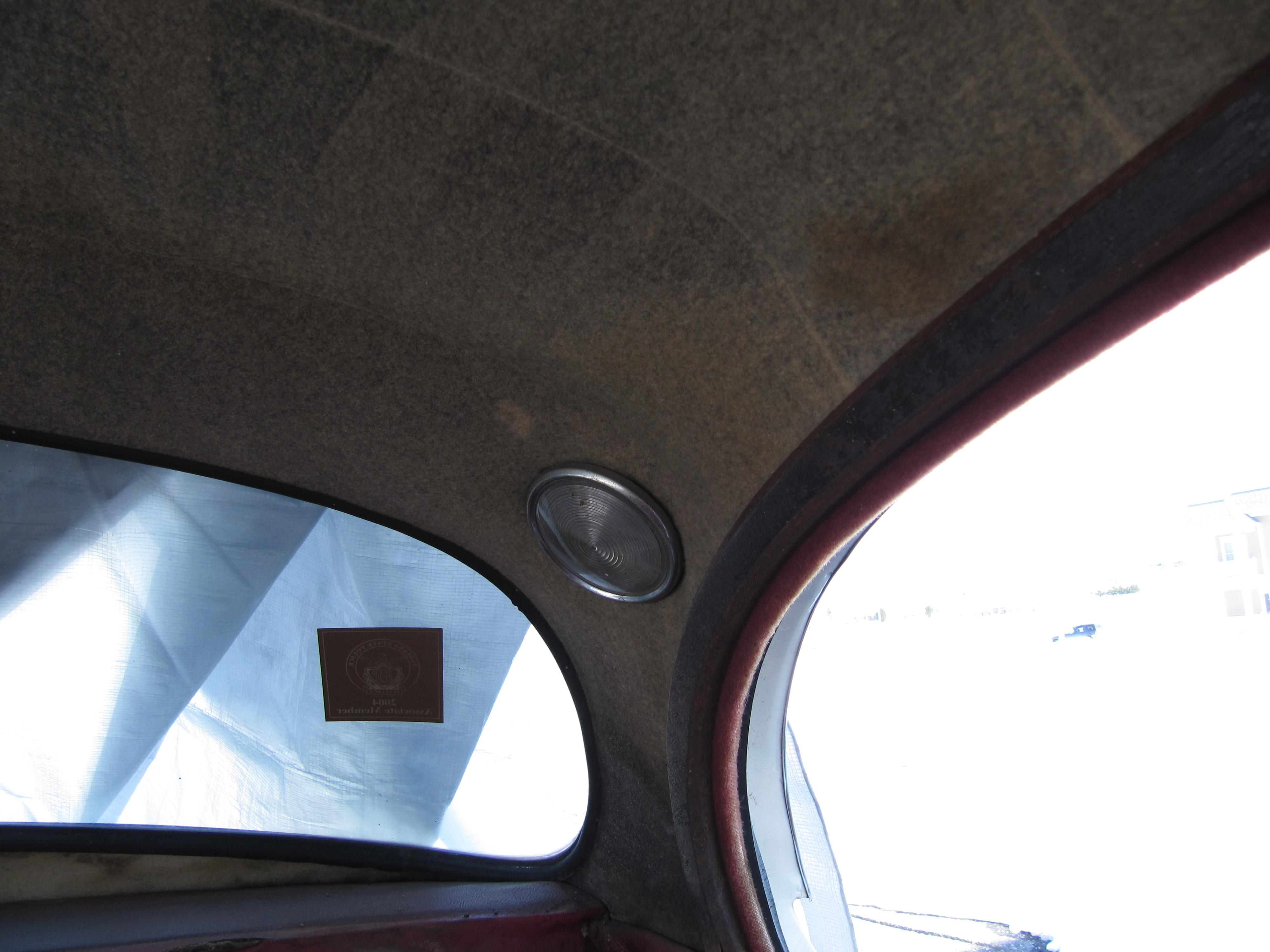
I trial fit the new, but as original, rear quarter lamps which required making new plywood mounting frames. Wiring for the rear quarter interior lamps initiates at fuse box to the interior lamp switch on the gauge panel and then proceeds through the LH and RH sills to the lamps. There is also a switch in each door that activates the interior lamps should any of the four doors be opened. I did not use wiring pigtails for these lamps. 36 mm festoon bulbs in warm white were substituted for the original incandescent bulbs.

Rear Quarter Interior Lamp
LH rear quarter interior lamp
I am using XJ40 powered seats in my MK2. The seat headrest lights were originally wired in such a way that they too illuminated when the car’s doors were opened. These lights also have an integral on/off rotary or dial switch. Without the central processor of a more modern car it would be all too easy to leave these lights on and eventually drain the battery. Therefore, I elected to wire these lamps to a switched power source rather than a constant power source like the other lamps. I did not use the terminal on the headrest light that would normally have a red/green wire to the door switches.
XJ40 Hedrest Lamp Installation
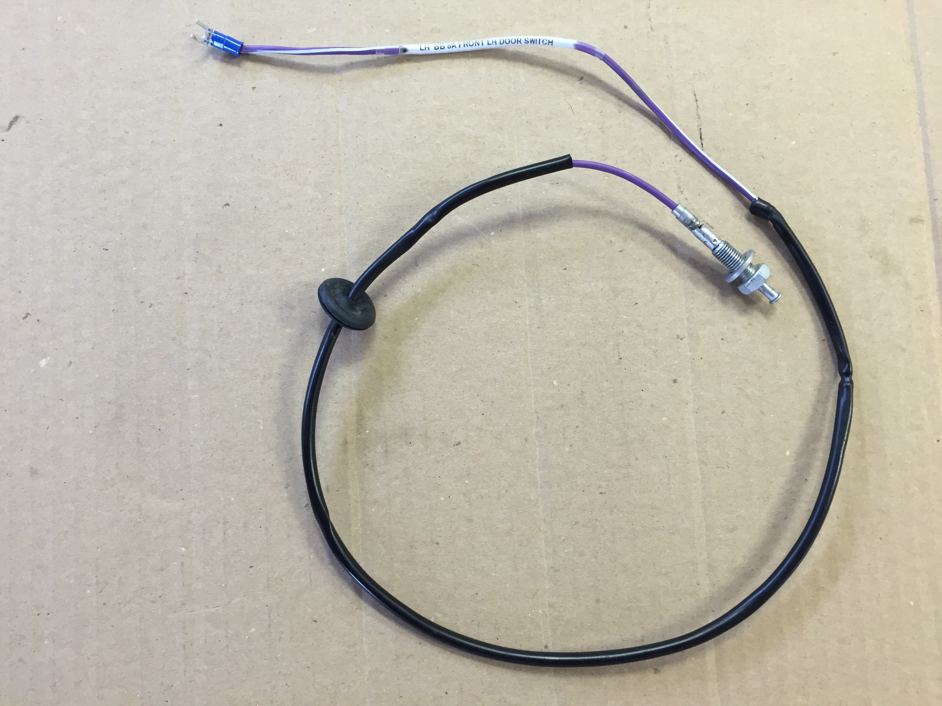
I was able to use the original door switches in my rebuild. I just rewired each of them with new wire.
Front Door Interior Light Switch and Wiring
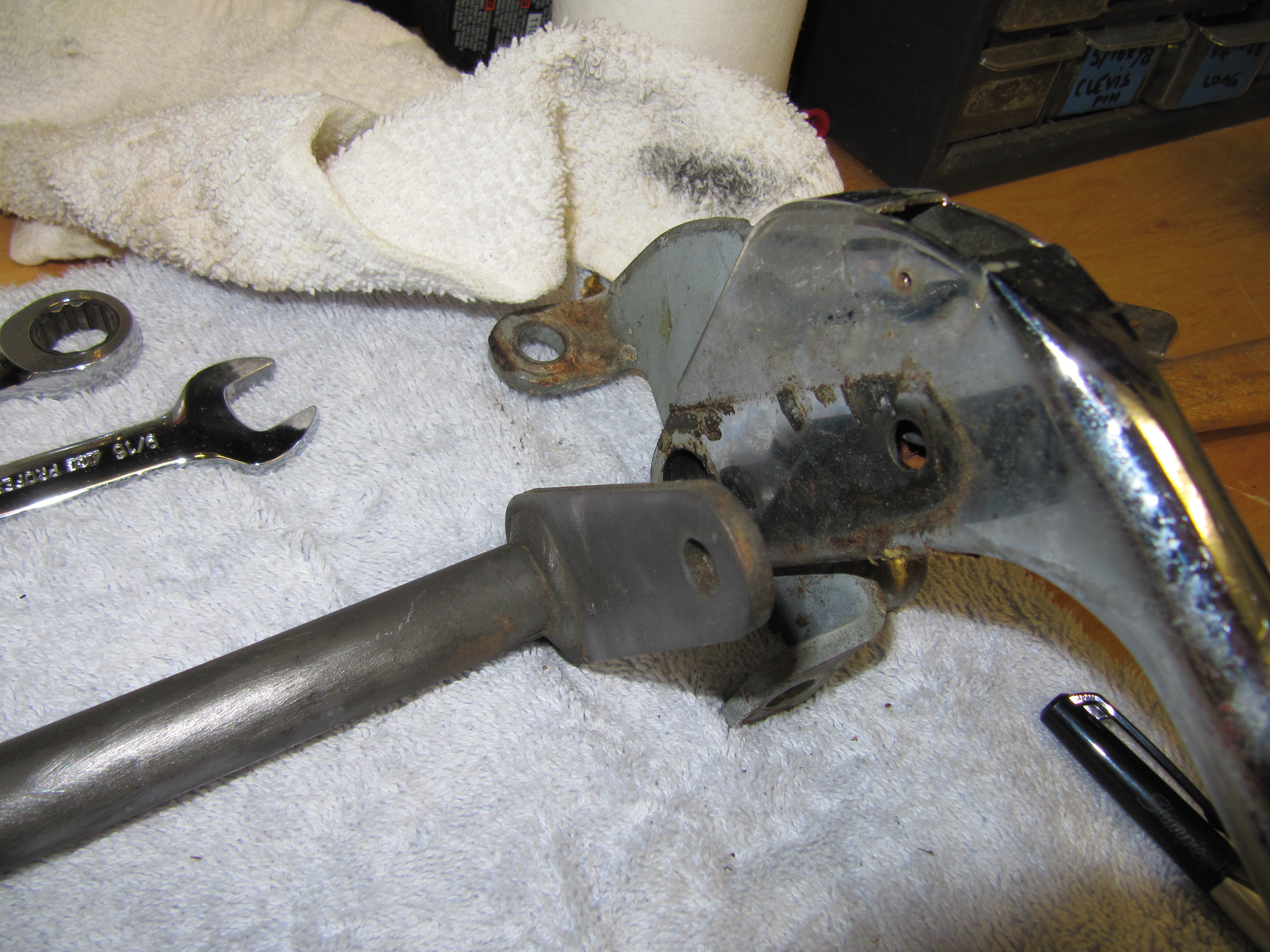
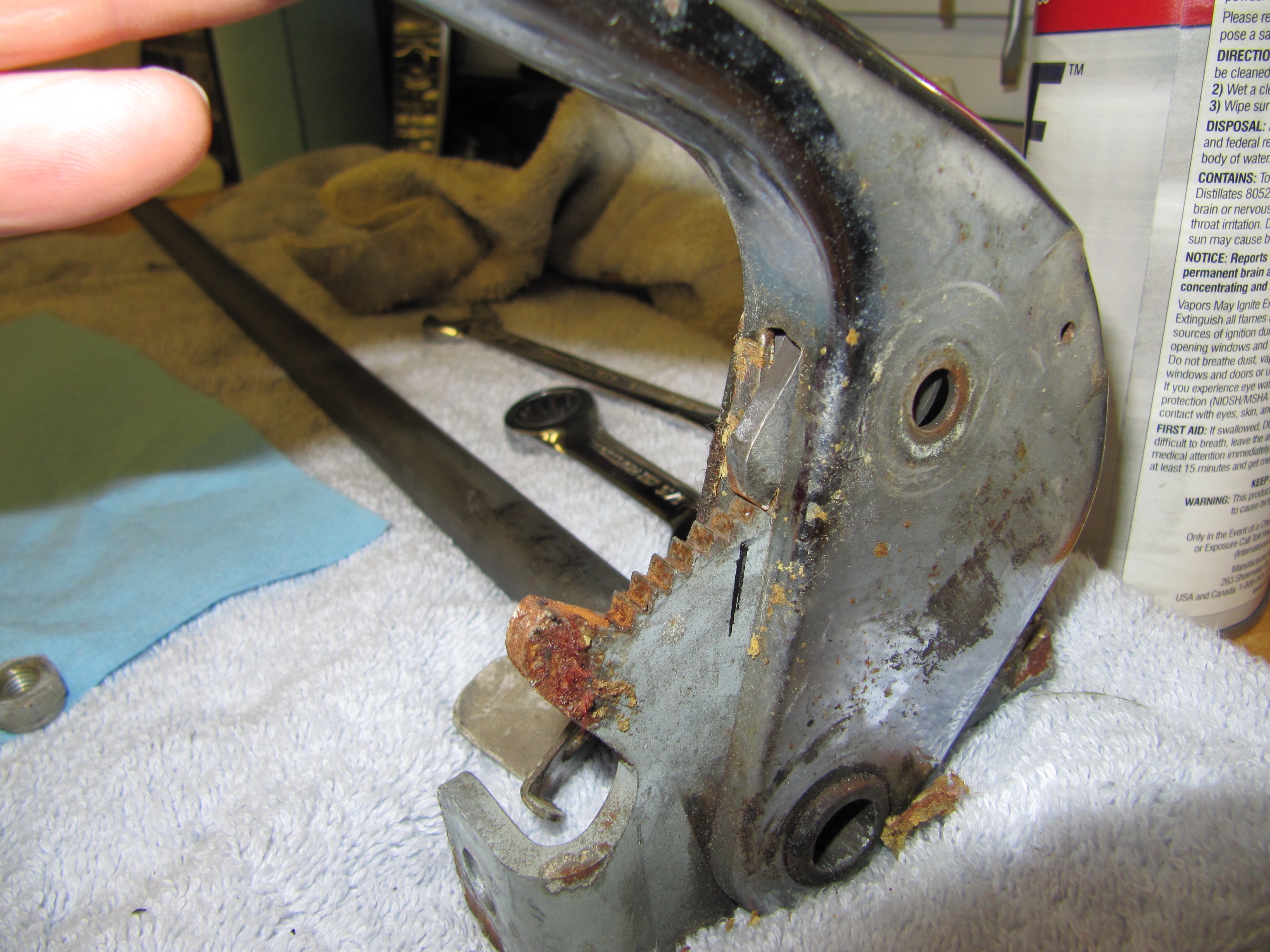
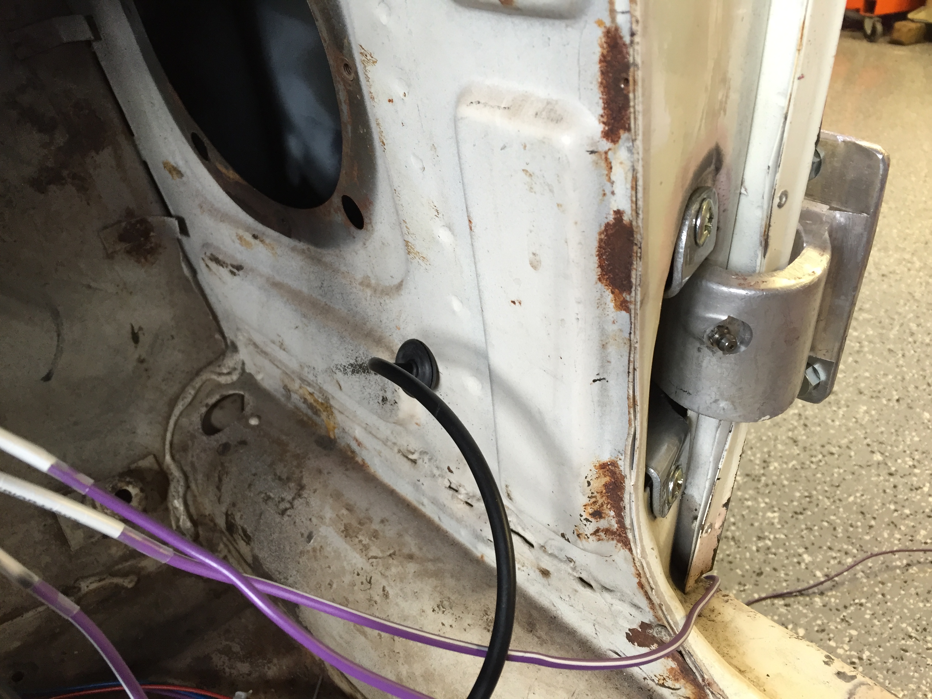
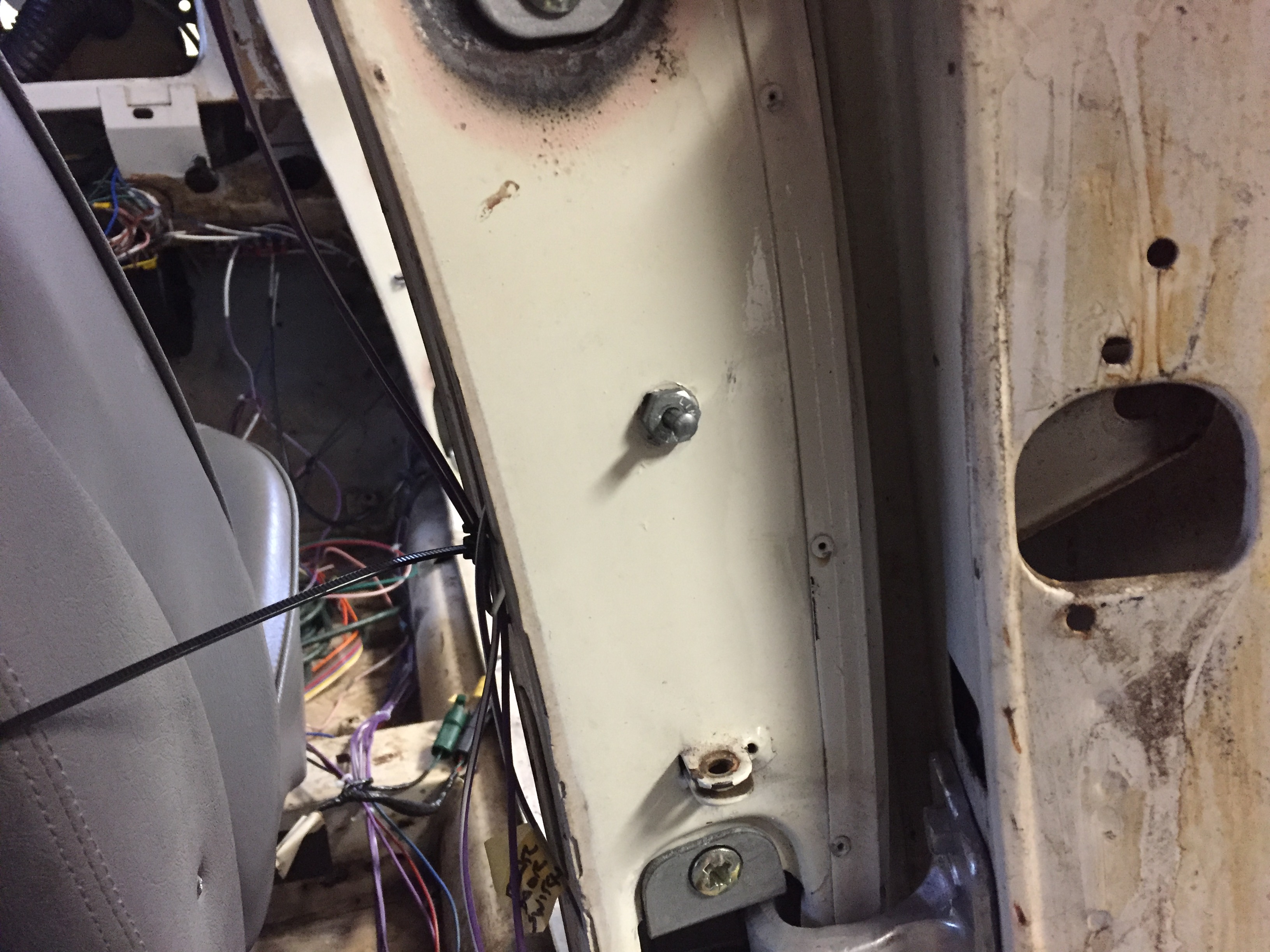
The front door switch is mounted in the lower door hinge and travels through the kick panel to the switch.

Front Door Interior Light Switch in Lower Door hinge
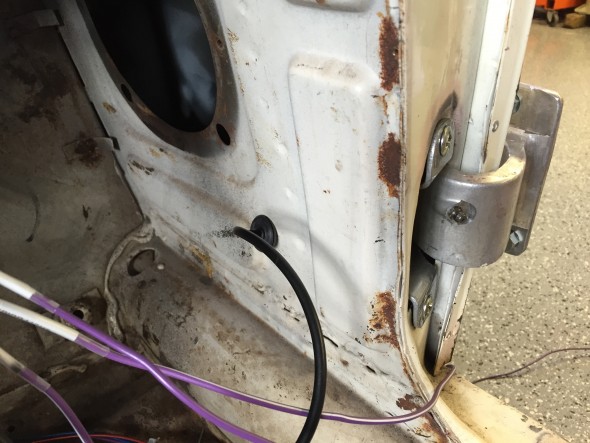
Front Door Interior Light Switch Wiring through Lower Kick Panel
The rear door switch is mounted in the rear side of the B/C post or center pillar. The wiring for the switch travels from under the front dash, through the sill and up the center pillar.

Rear Door Interior Light Switch in Center Pillar
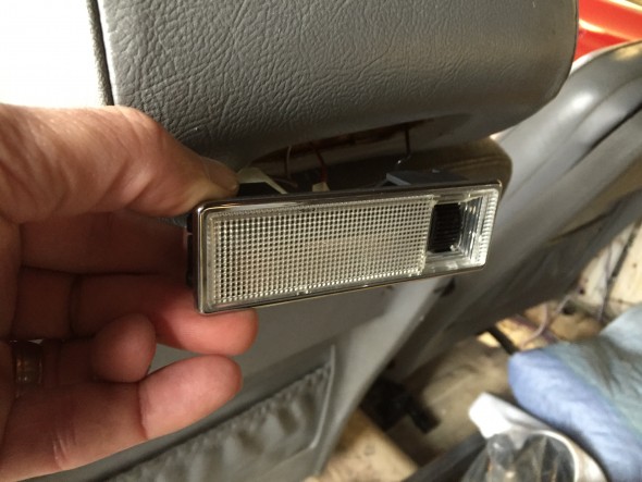
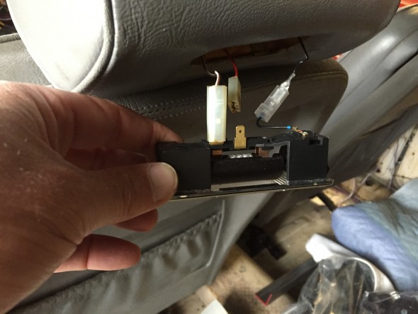
The Cubby Box lamp assembly wiring for Lamp/Switch consists of a metal base fixture, bulb, blue plastic cover and a switch controlled by opening the Cubby Box door. More images and information regarding the lamp may be found at the “Interior Lights” post. As with the other interior lamps, the original incandescent bulb was replaced with a 36 mm festoon bulb in warm white. Terminals on the back side of the metal lamp base connect to the fused power source and to the Cubby Box door switch. The image below illustrates the wiring sources and terminations for the Cubby Box.
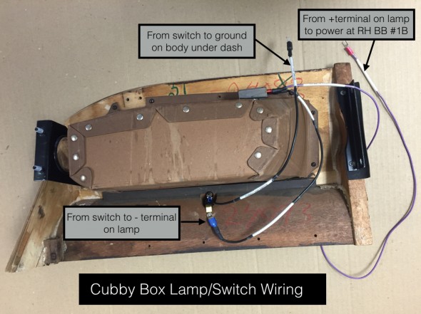
Cubby Box Wiring for Lamp/Switch
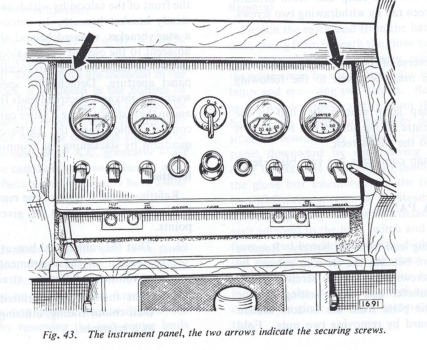
Some Details on a Few Other Assemblies
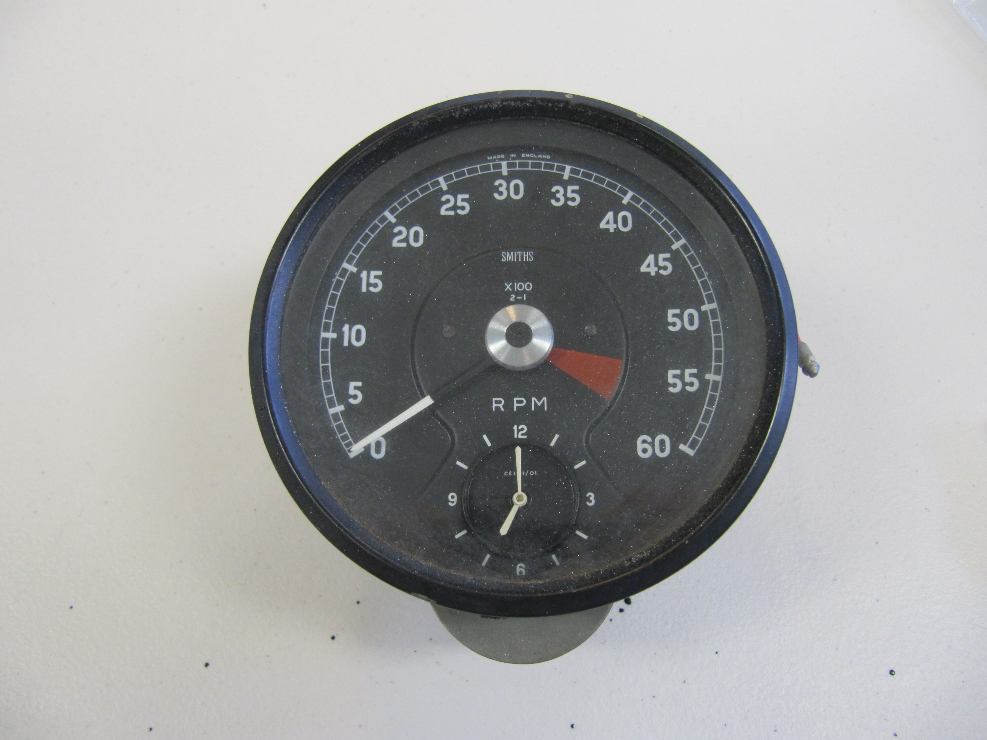
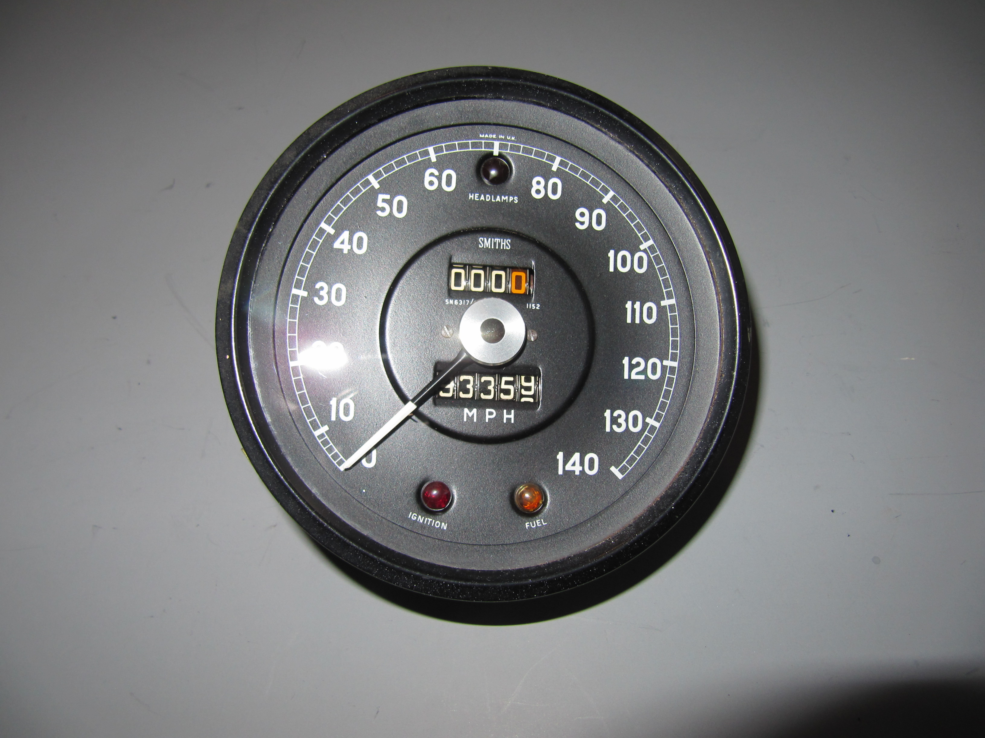
The LH and RH Fascia Board Assemblies were installed in the car so as to test the wiring for the speedometer and its warning lights, the tachometer with the internal clock, the “Handbrake “ON” position and brake fluid container level” warning lamp, and the “Cubby” glove box lamp. More information on these fascia boards may be found at the “Dash” post. All gauge/instrument illumination incandescent bulbs were replaced with LEDs.
I first connected the left turn signal flashing indicator, the right turn signal flashing indicator, and the overdrive engagement indicator from the indicators wiring pigtail to the direction indicator/headlamp flasher switch. A ground wire for the indicators was mounted to the body below the dash.
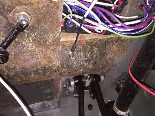
Ground connection under dash for indicator lights
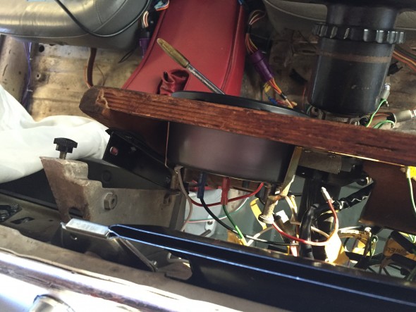
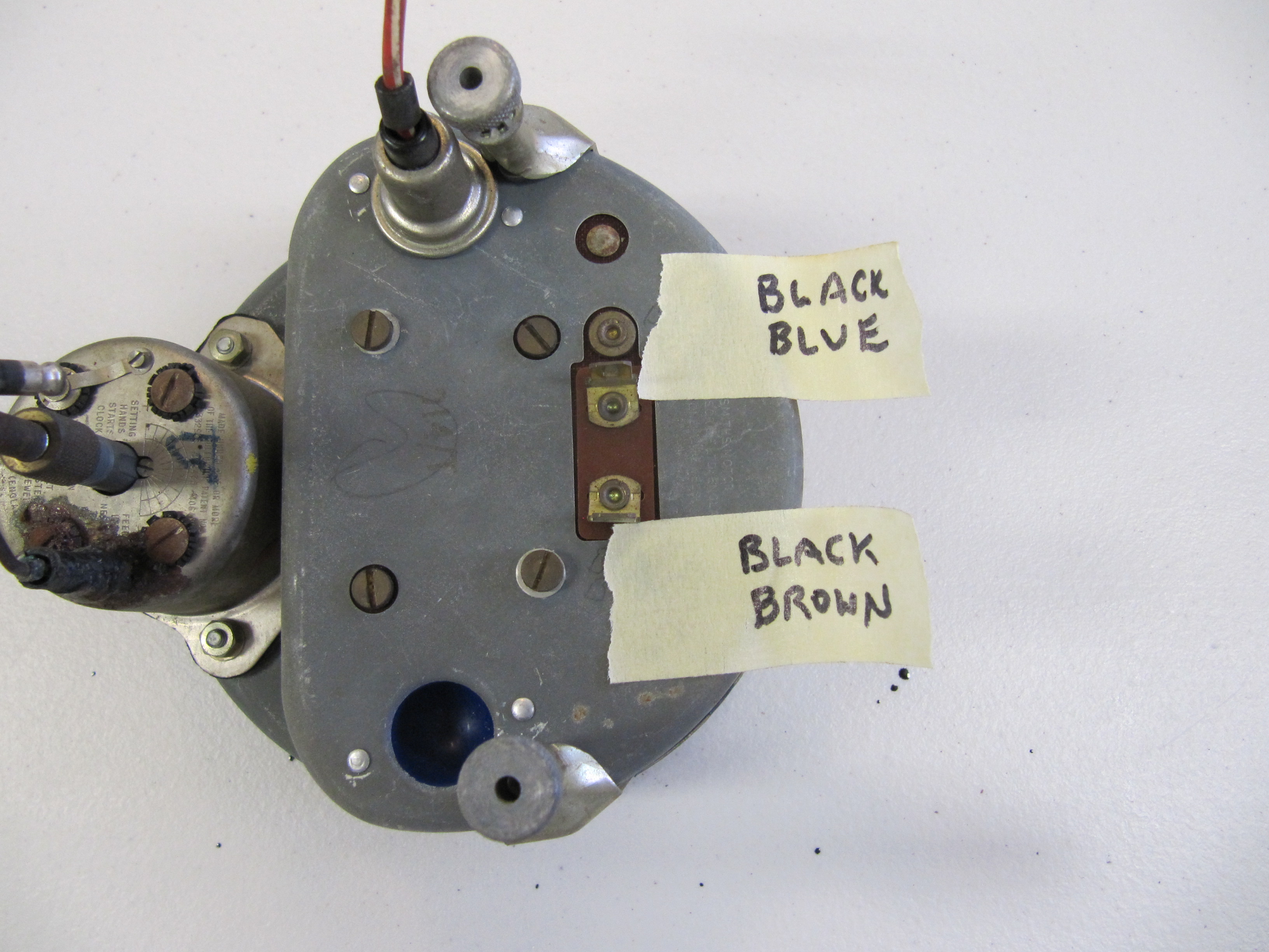
Loose fitting of fascia board for tach install
I found it easiest to loosely position the driver’s side fascia board and I then installed the tachometer with its two mounting clamps, a ground wire, the 12 volt power wire, the wire connecting the tach to the coil and the two instrument lights. Leaving the speedometer position open facilitates accessing the LH fascia board outside mounting studs/nuts.
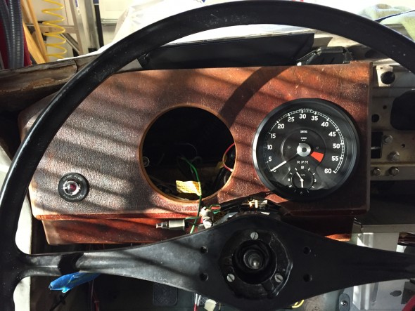
LH fascia board temporary install with tach in place
I then secured the LH fascia board to its mounts, followed by connecting the wiring for the handbrake/brake fluid level warning lamp.
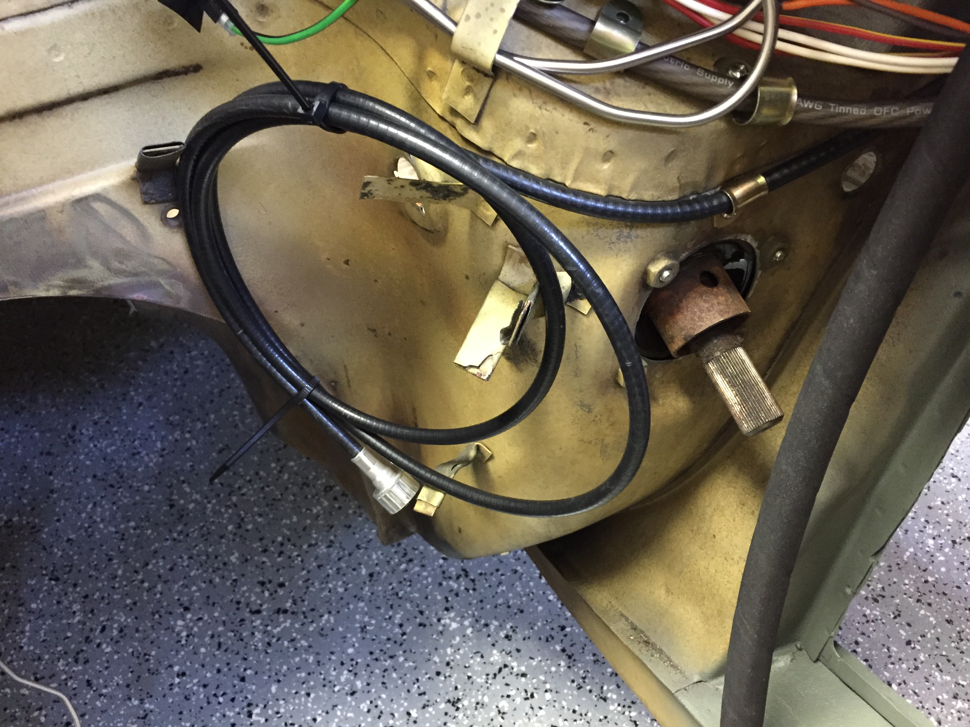
I then connected the two speedometer illumination lights, the lights for the headlamp, ignition, and fuel warning lights, and the speedometer drive cable.
Installing the passenger side (RH) fascia board is much the same as the driver’s (LH) side. A sliding panel in the cubby box may be removed to provide access to the studs/nuts of the outside mounting bracket. The wiring for the “Cubby” lamp as shown in the write-up and image above is connected to ground and power.
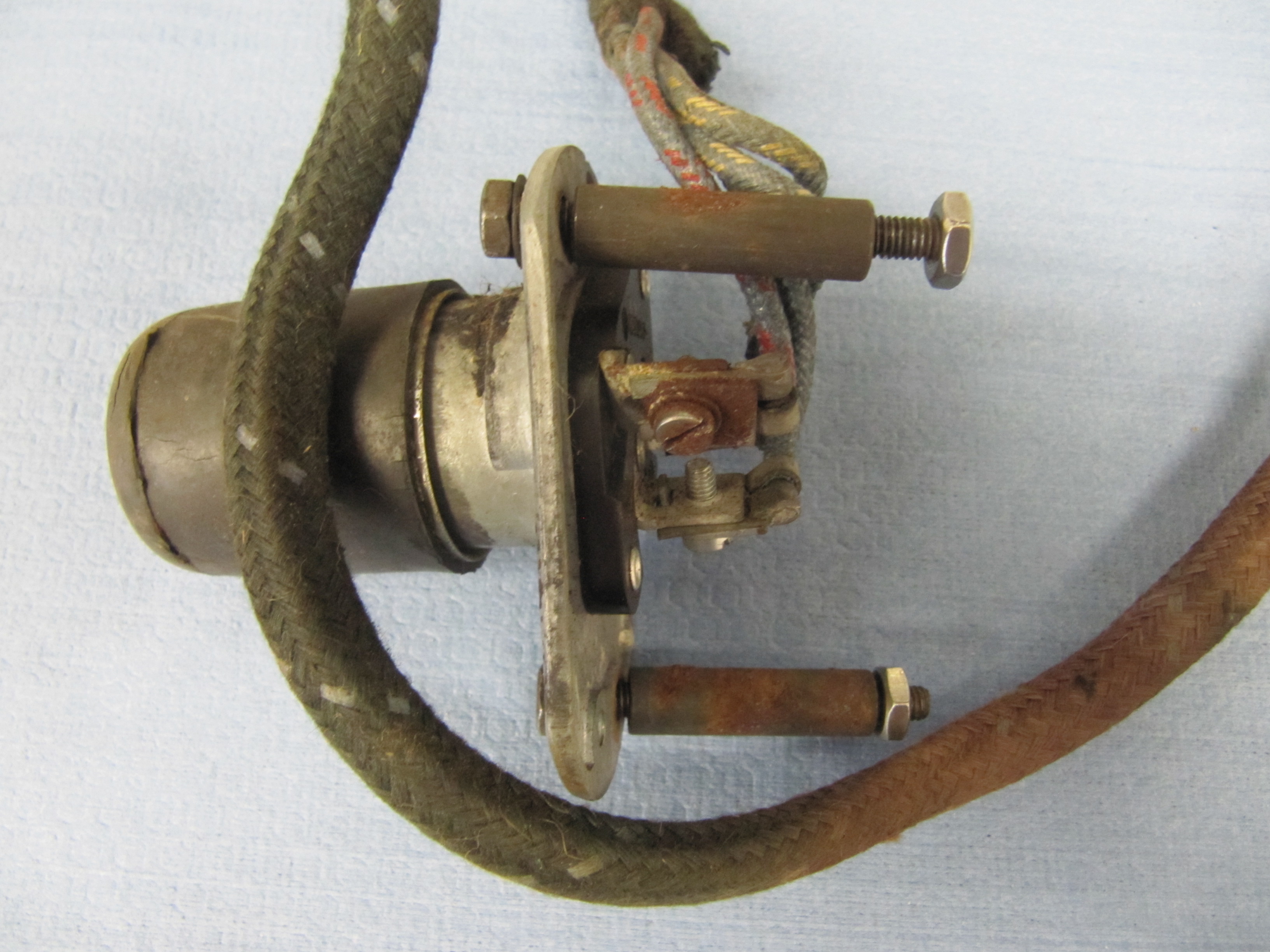
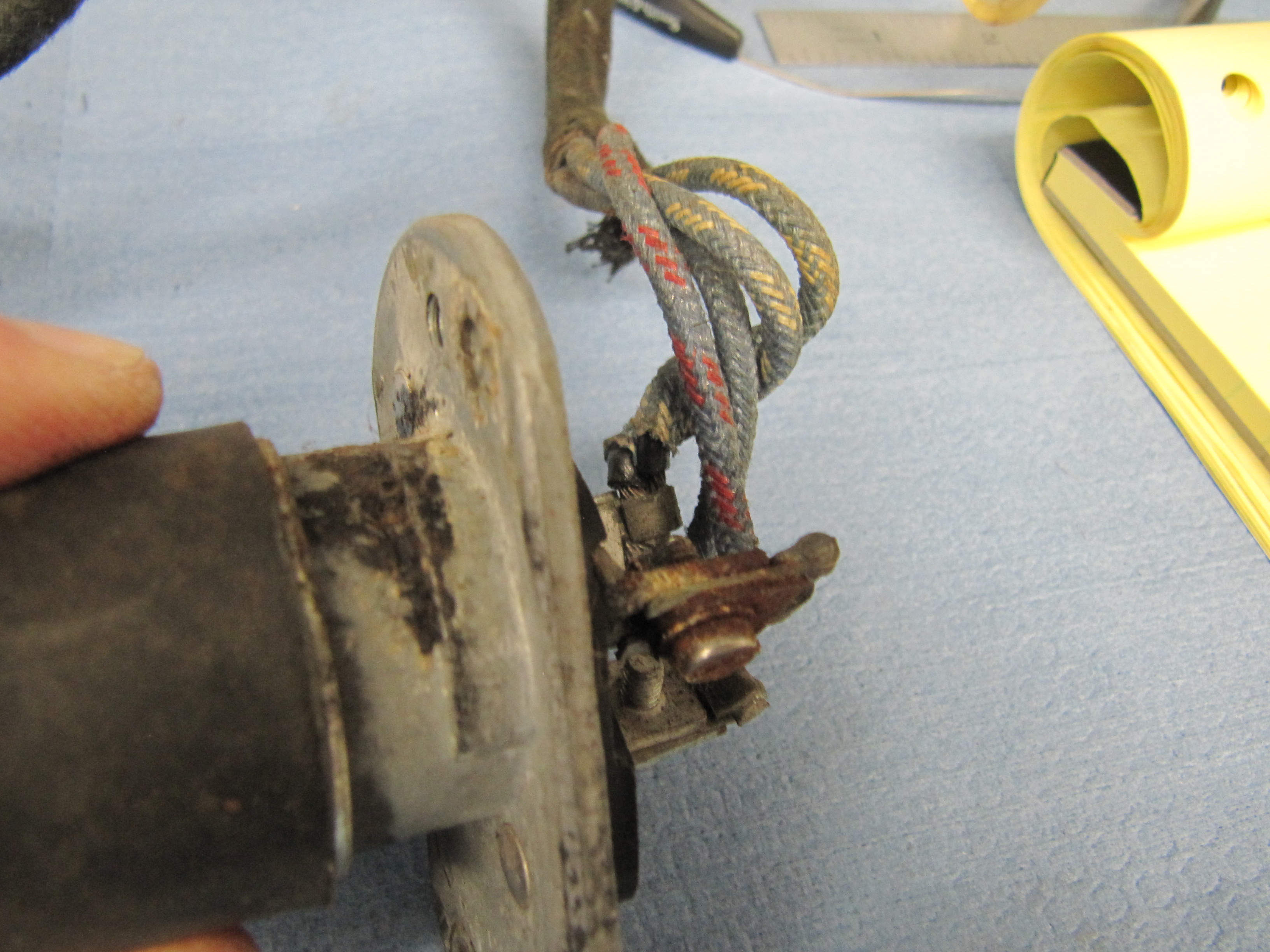
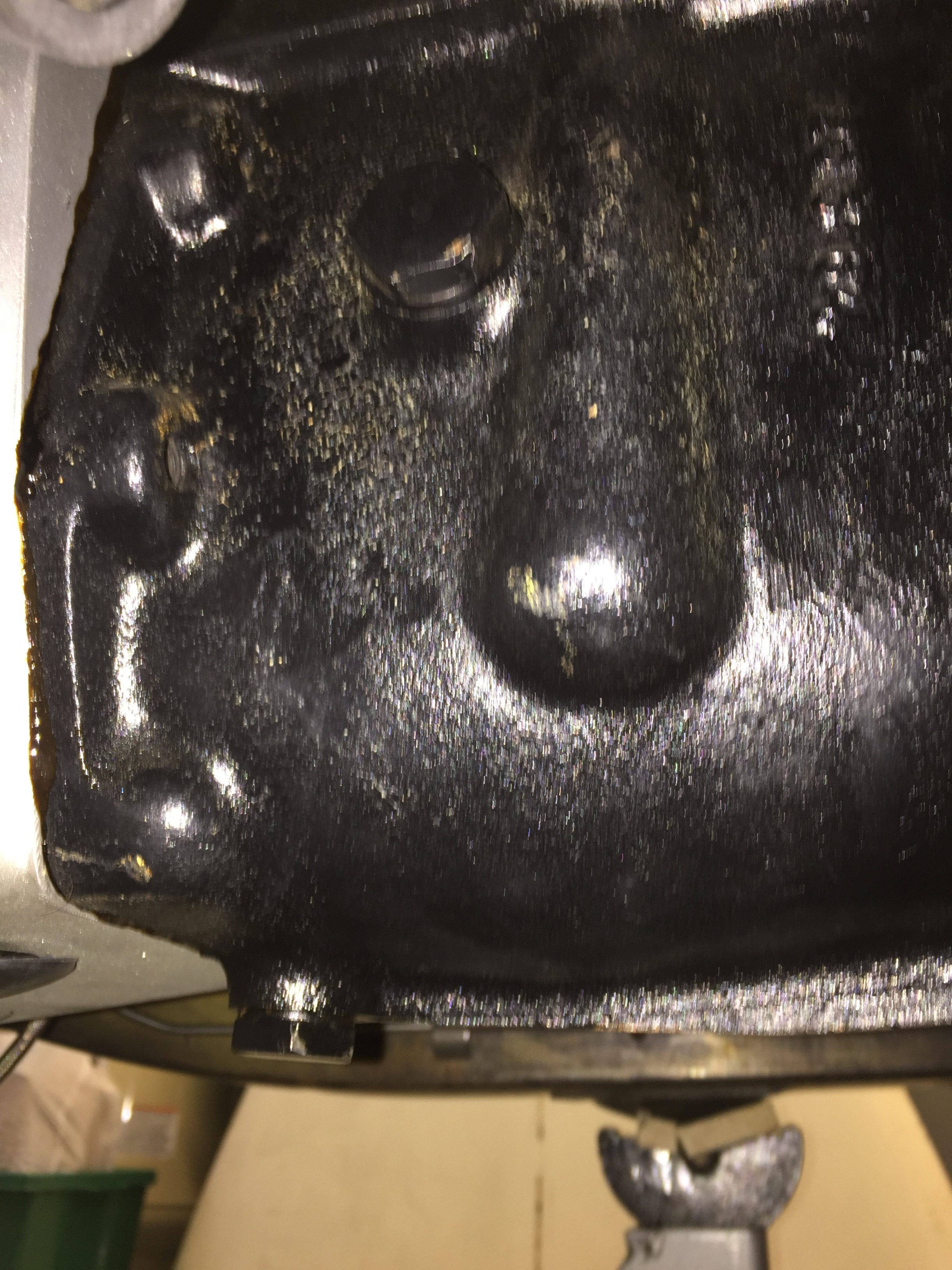
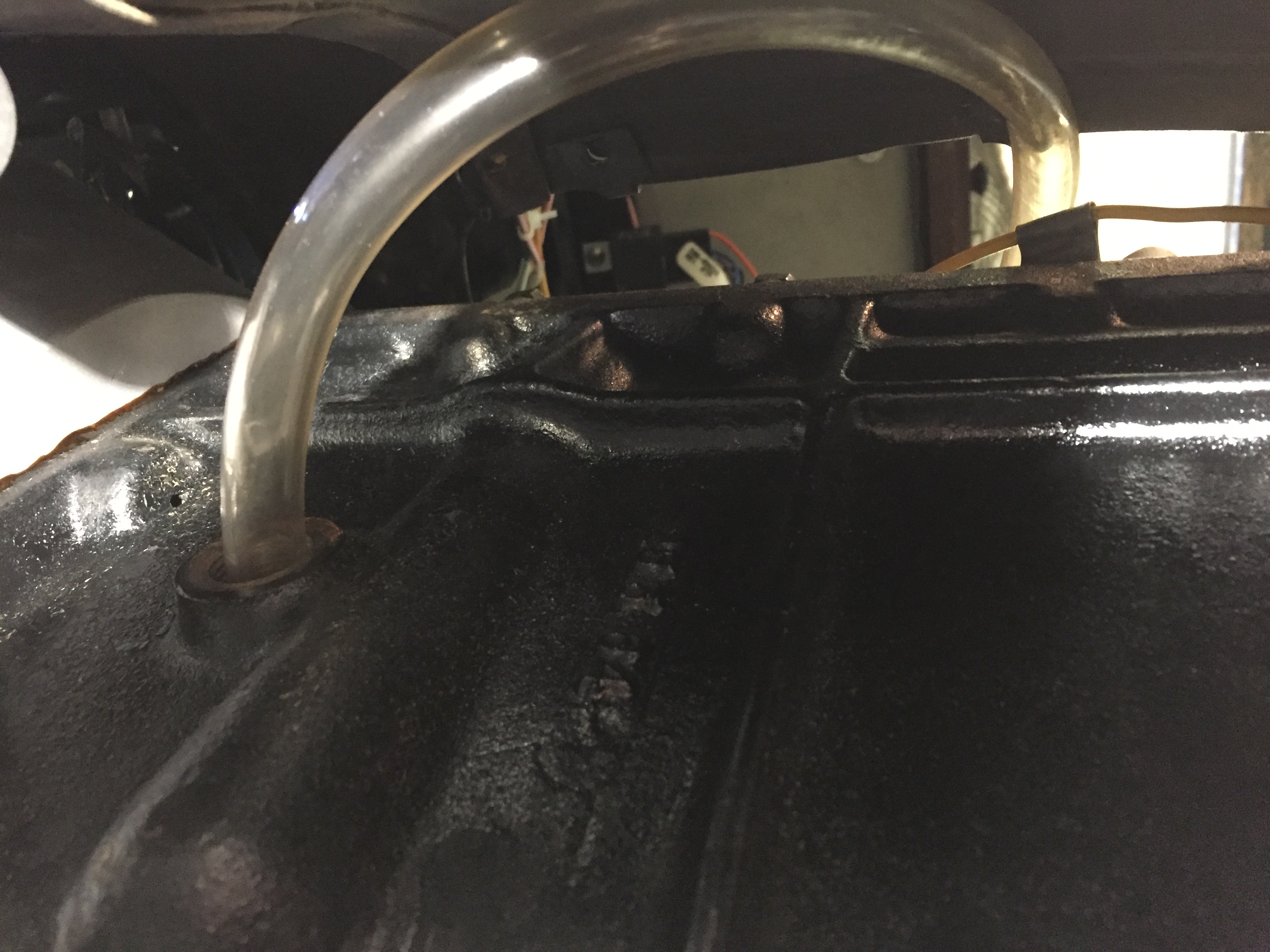
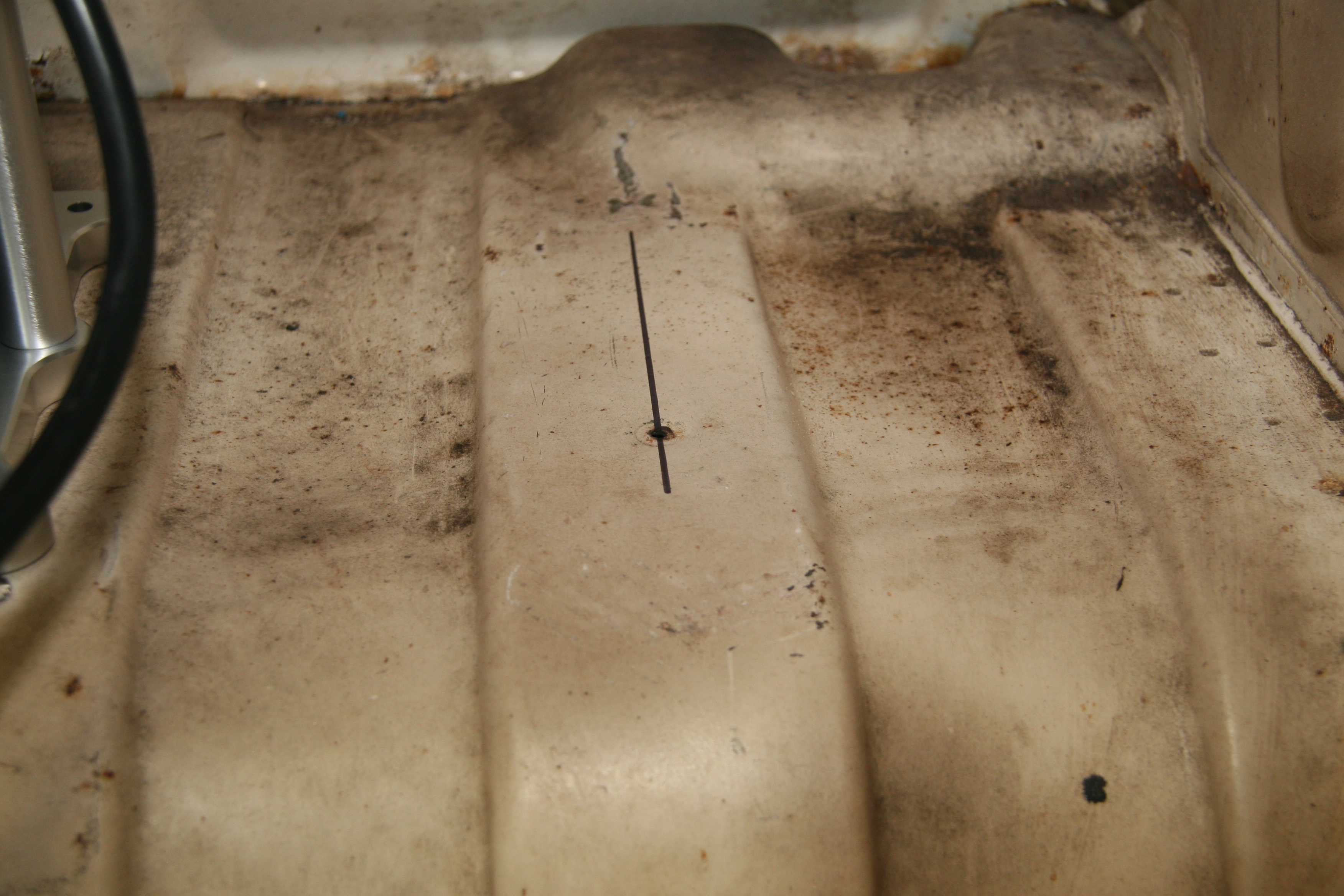
Fuel Sender
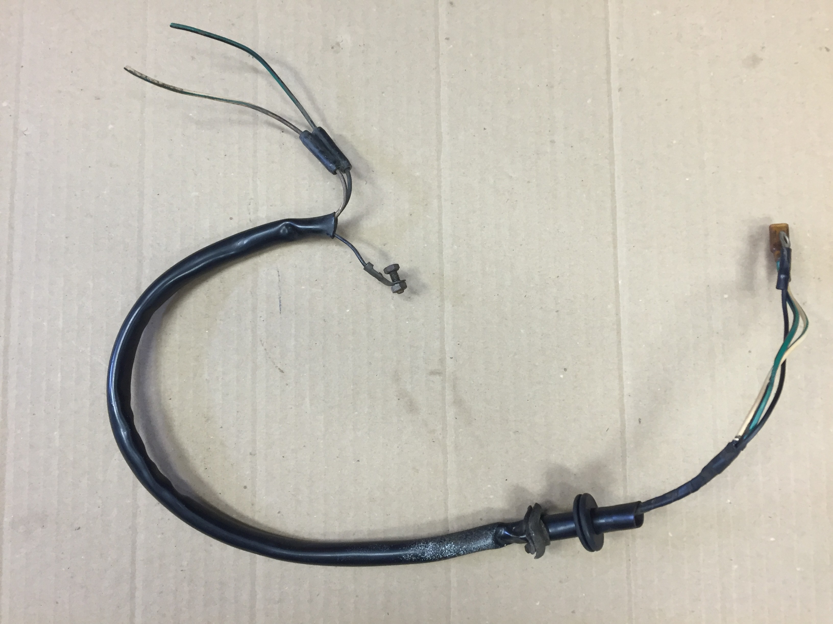
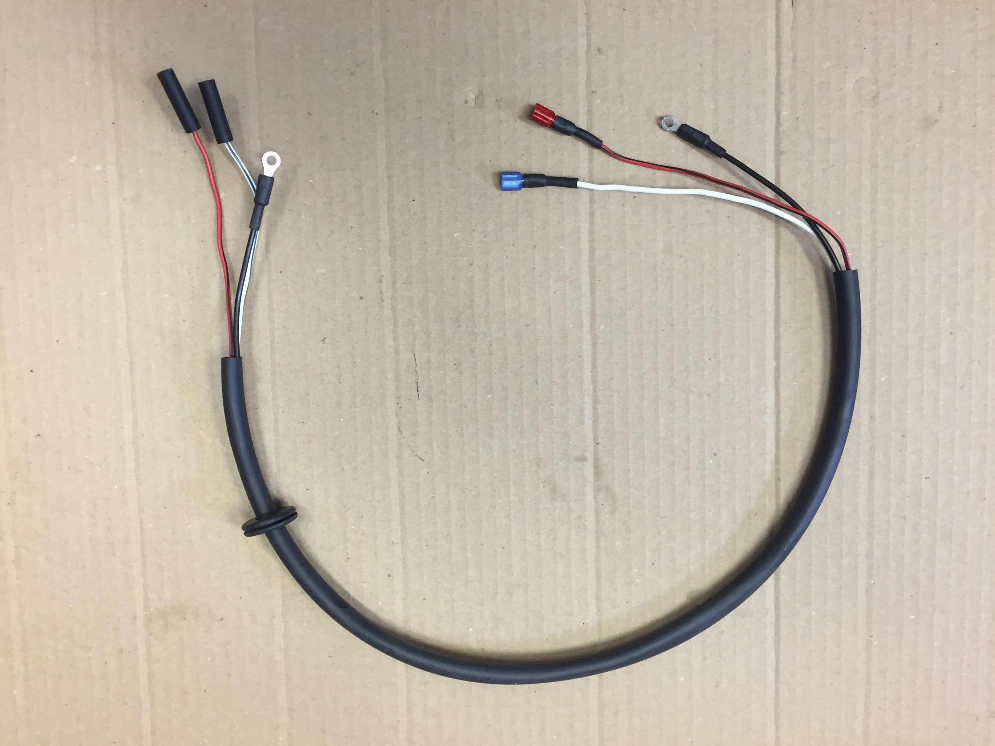
The fuel sender has its own short wiring harness consisting of three wires in a protective sleeving. One wire for ground, one for the fuel gauge (the “T” terminal on the sender for 10 volts) and one for the fuel level warning lamp in the speedometer (the “W” terminal on the sender). The embossed terminal markings are evident on the image below. My sender has an “E” marking for earth, although my grounding wire was fixed to one of the screws used to mount the sender to the tank. While the original harness was in good shape, I made a new one for installation in the Jag when the fuel tank is fitted.
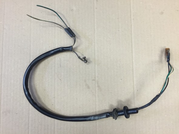
Original Fuel Sender Wiring Harness
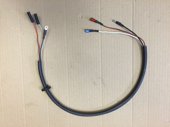
New Fuel Sender Wiring Harness
Fuel Sender Terminals
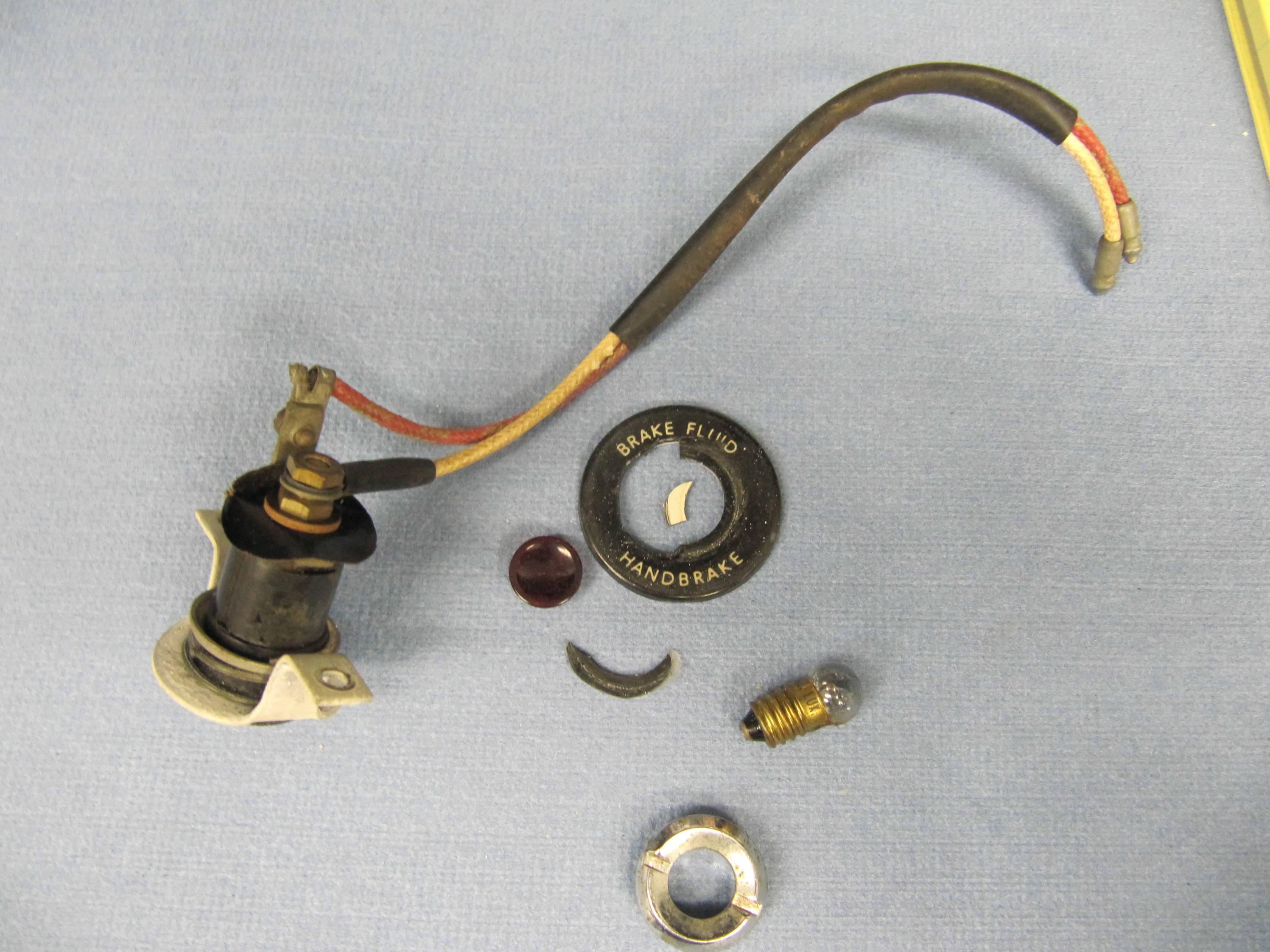
Warning Light for Handbrake and Fluid Level
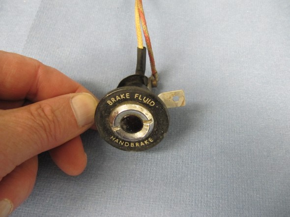
Handbrake and Fluid Warning lamp Escutcheon
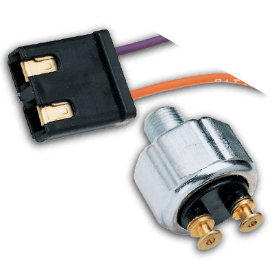
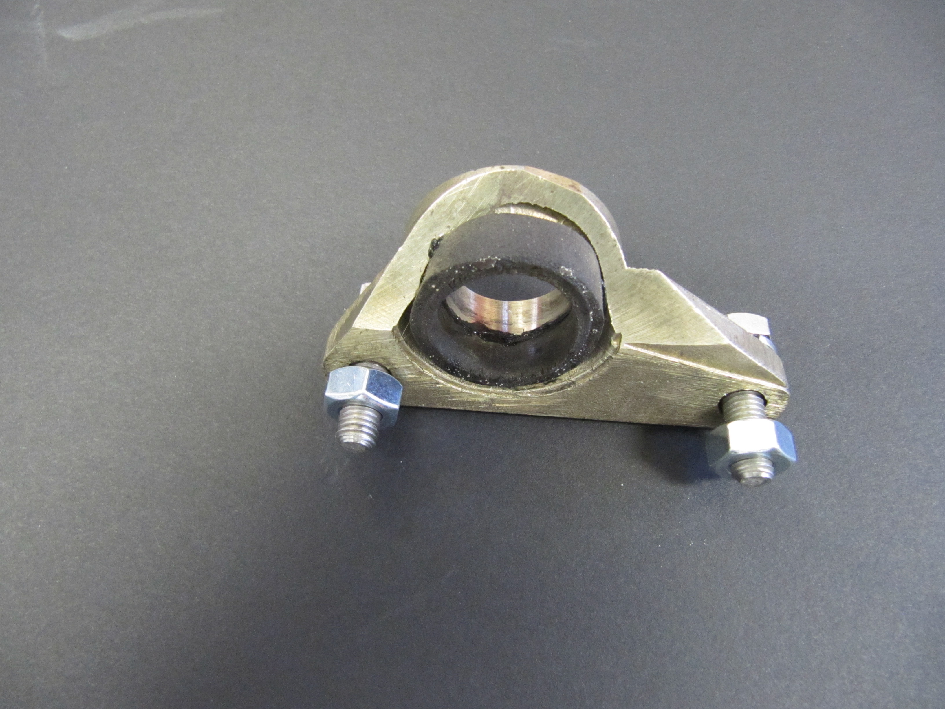
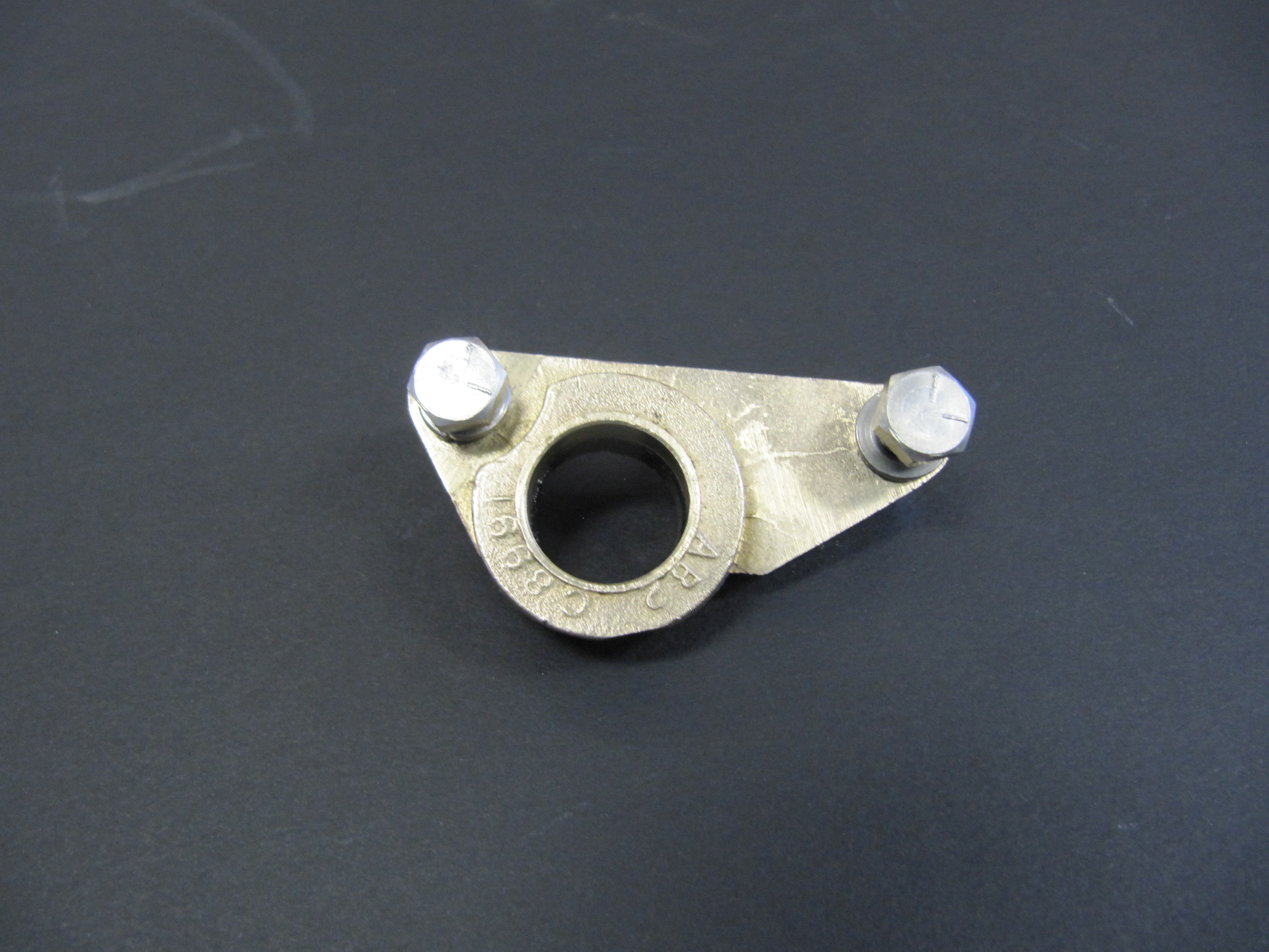
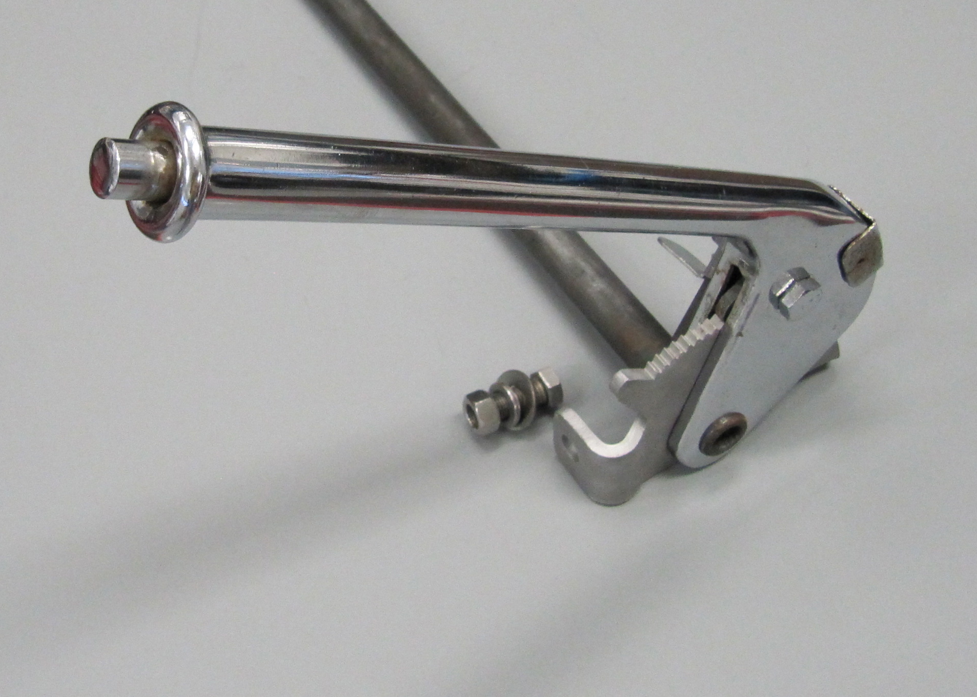
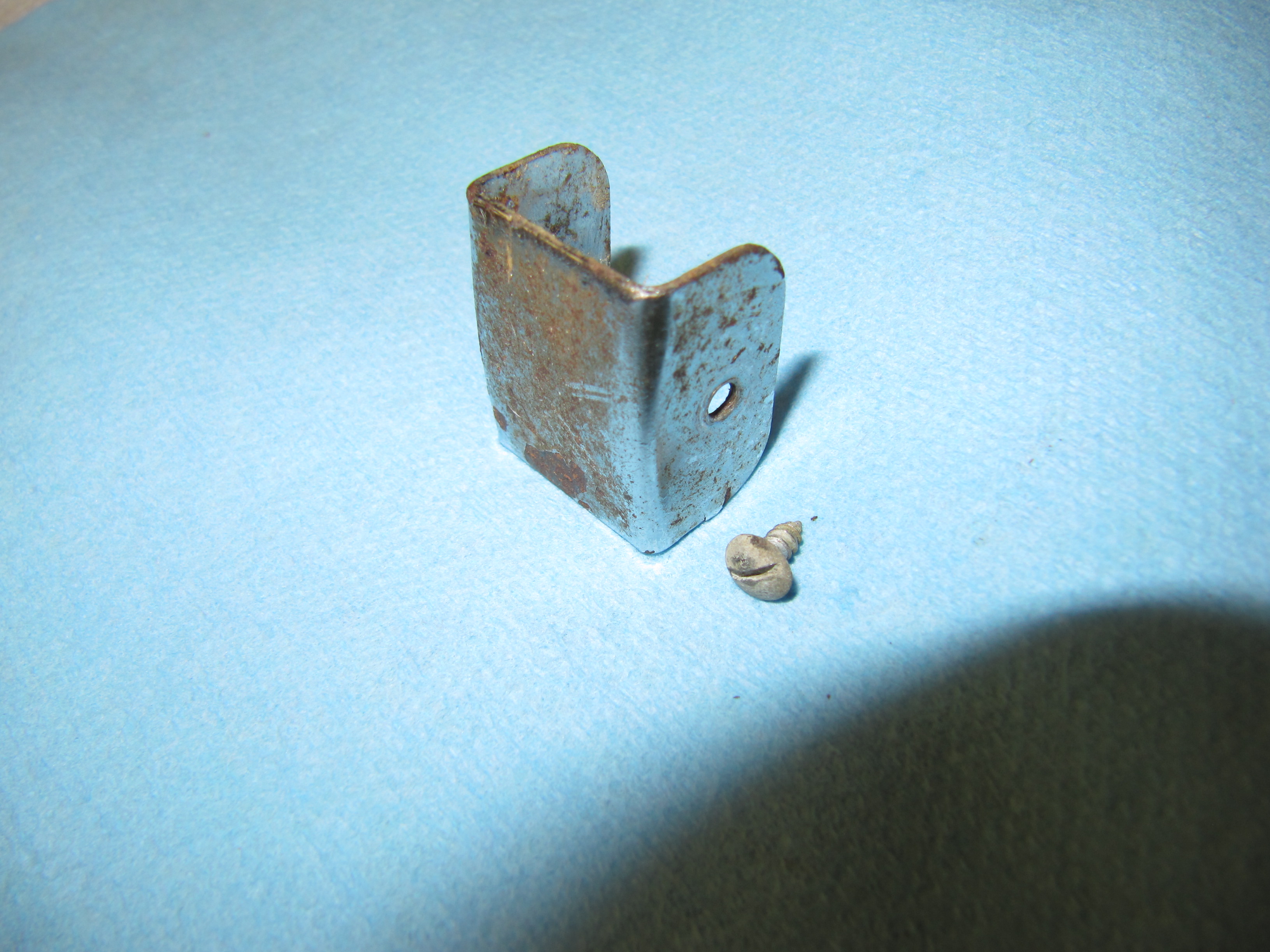
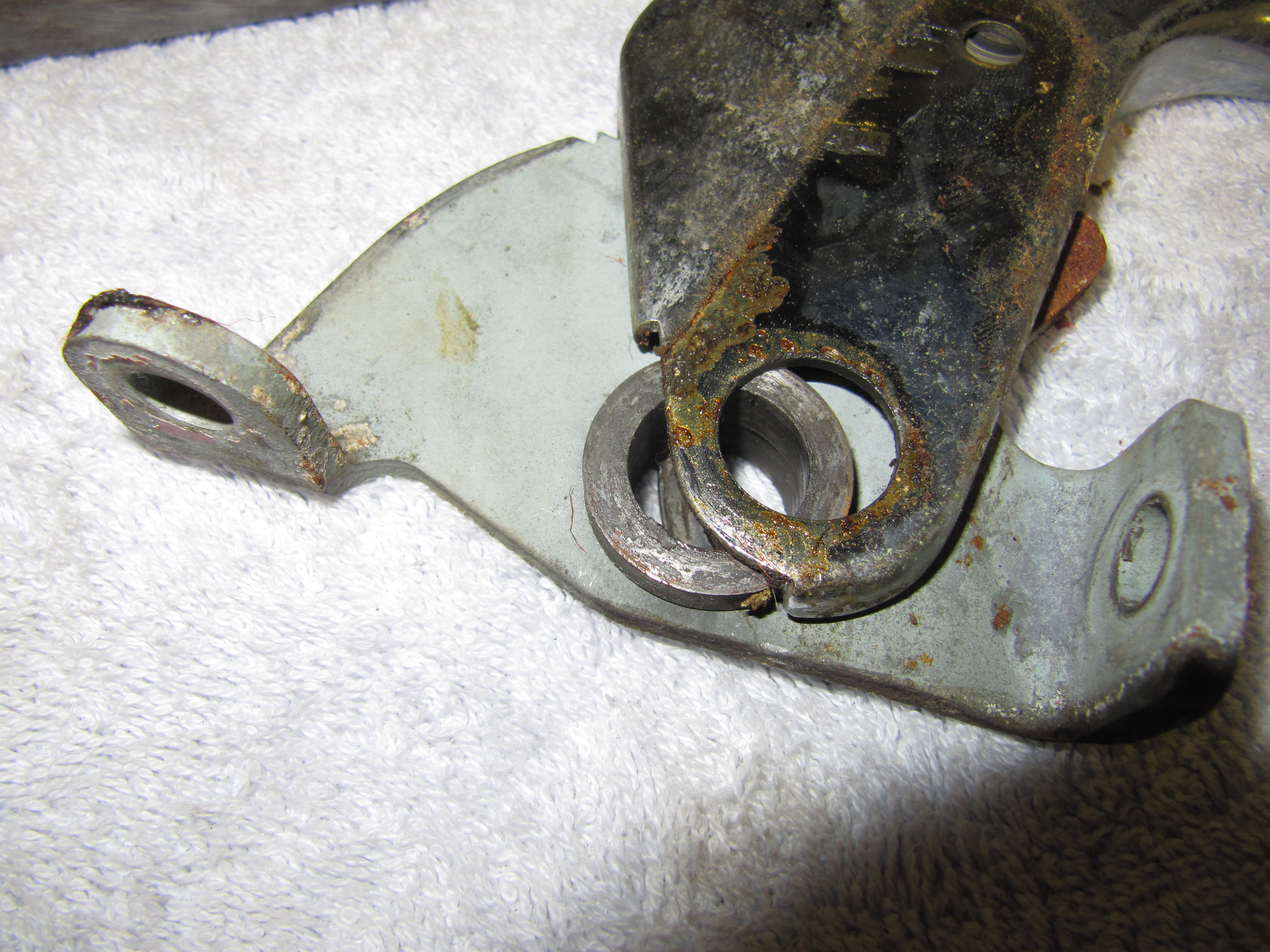
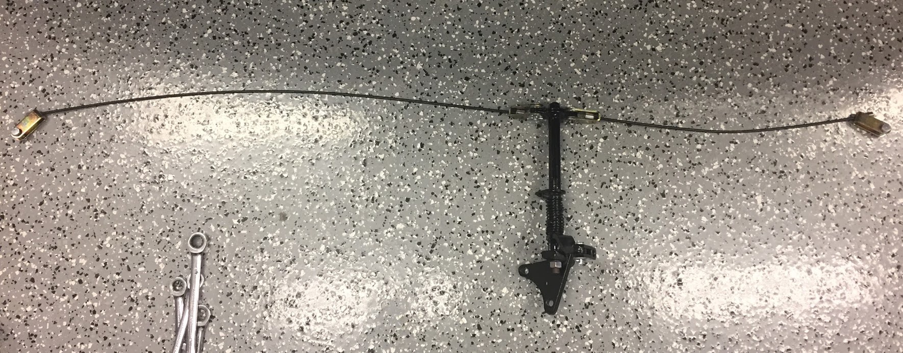
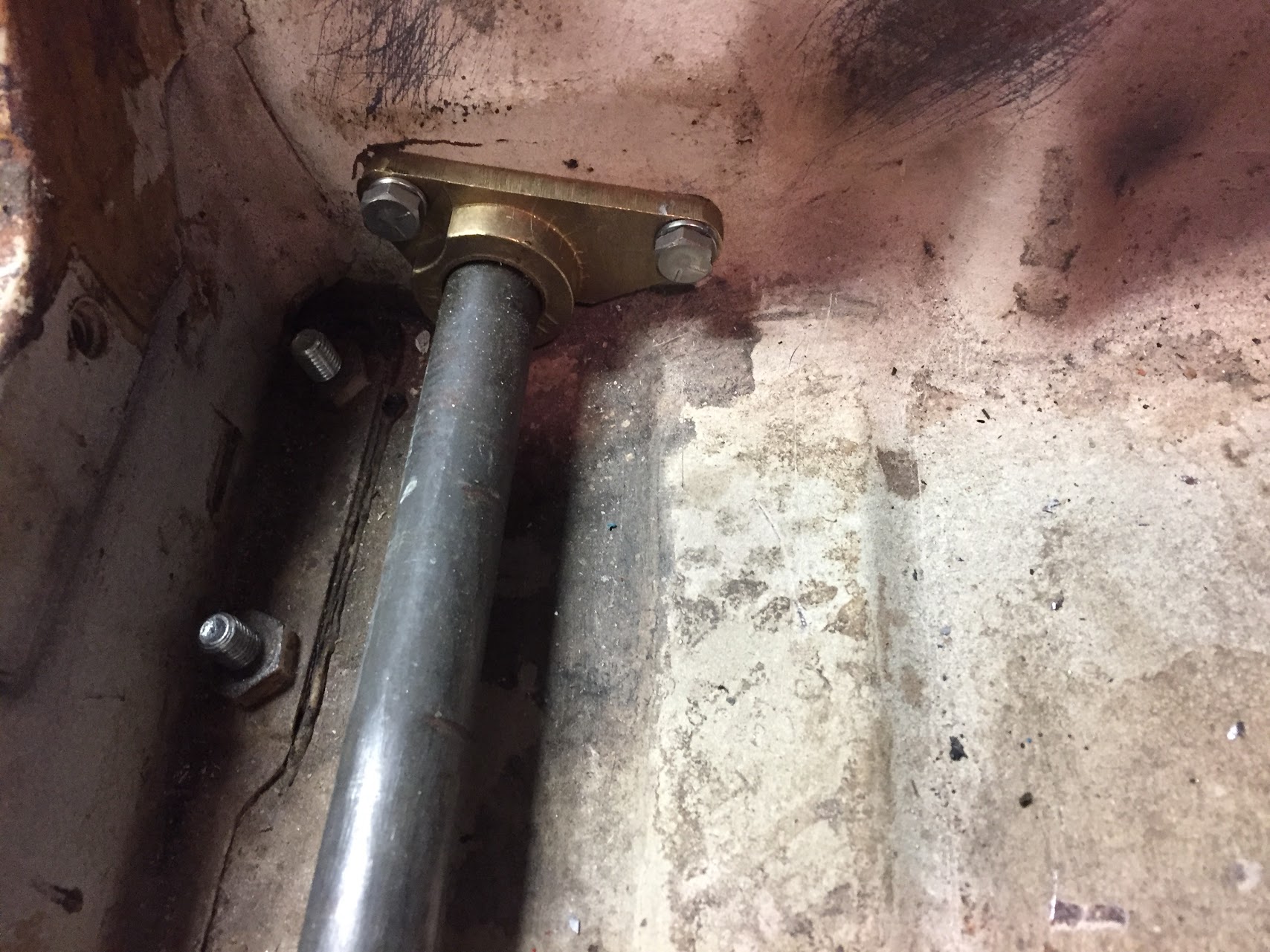
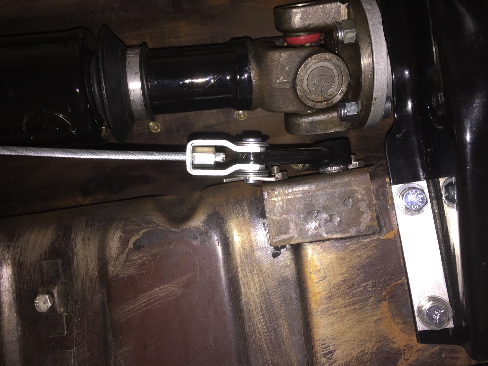
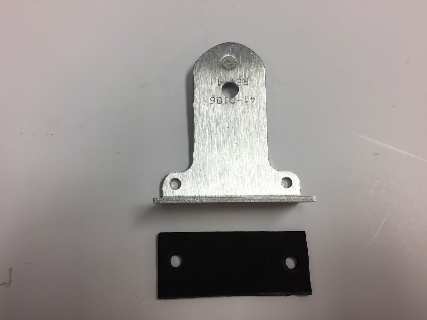
The lamp is activated by a switch at the base of the handbrake, mounted to a bracket located on the interior floor. See: https://valvechatter.com/?p=3913 under the handbrake post, or by a level indicator switch in the brake fluid reservoir is shown earlier in this post.
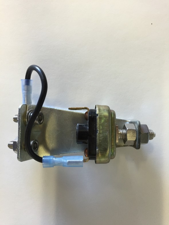
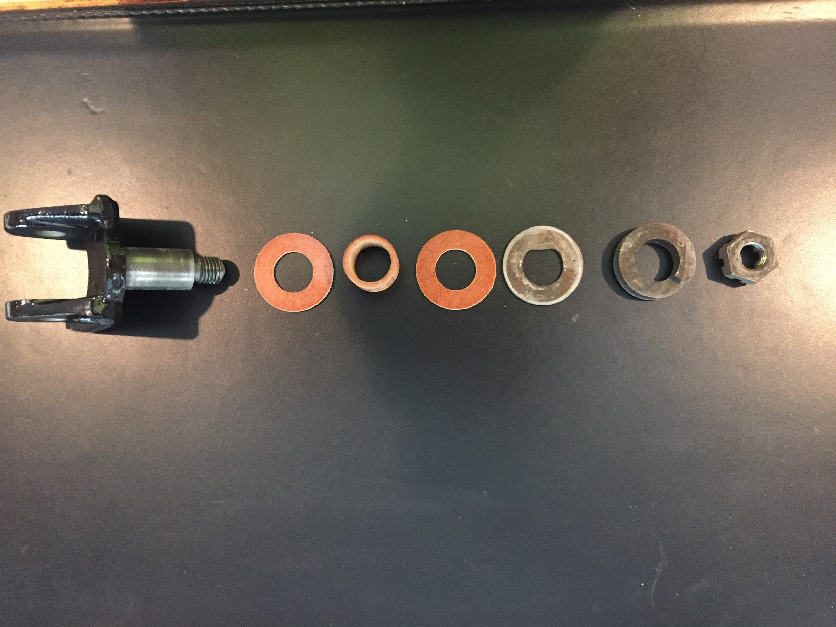
Handbrake Warning Switch
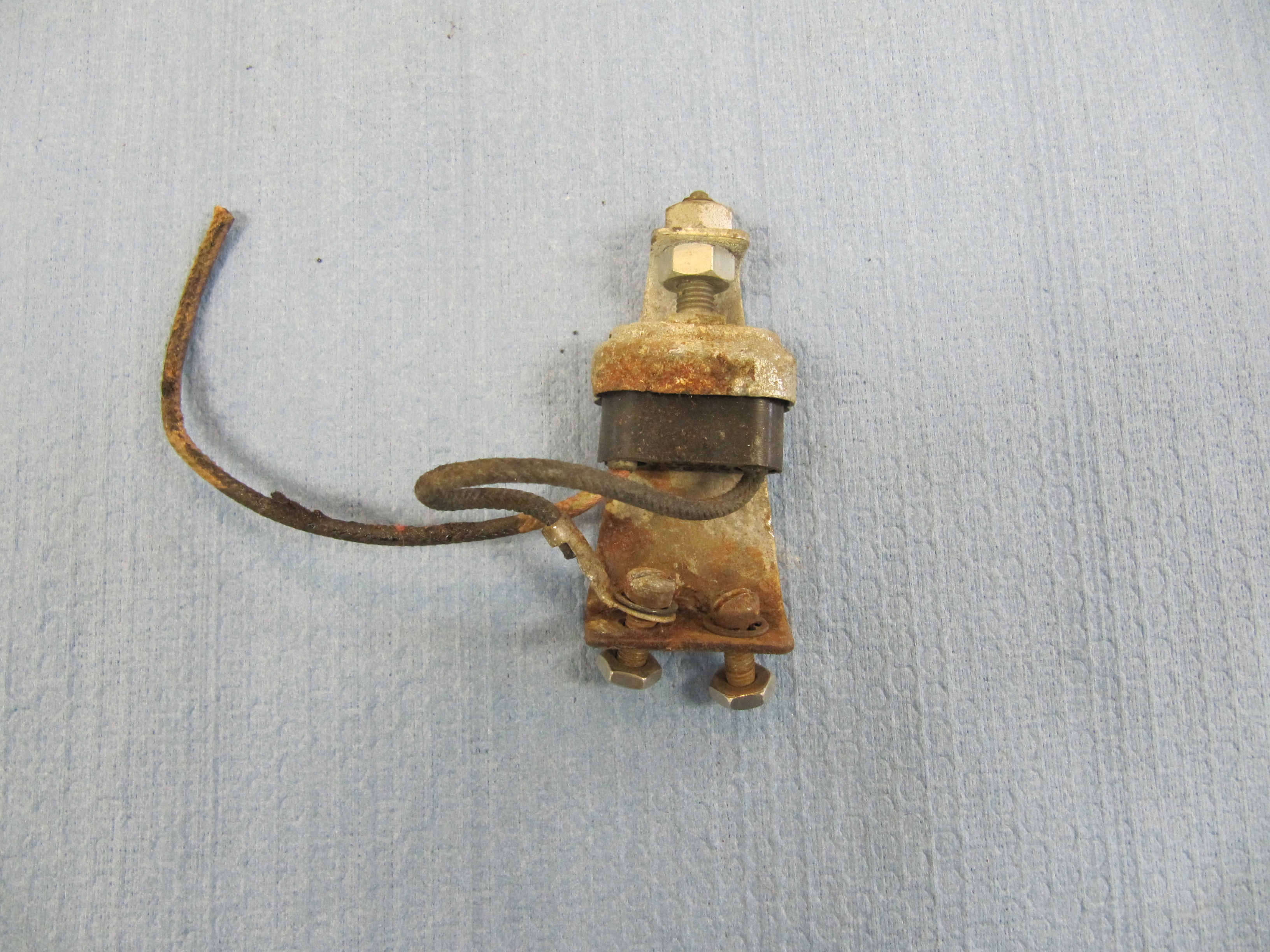
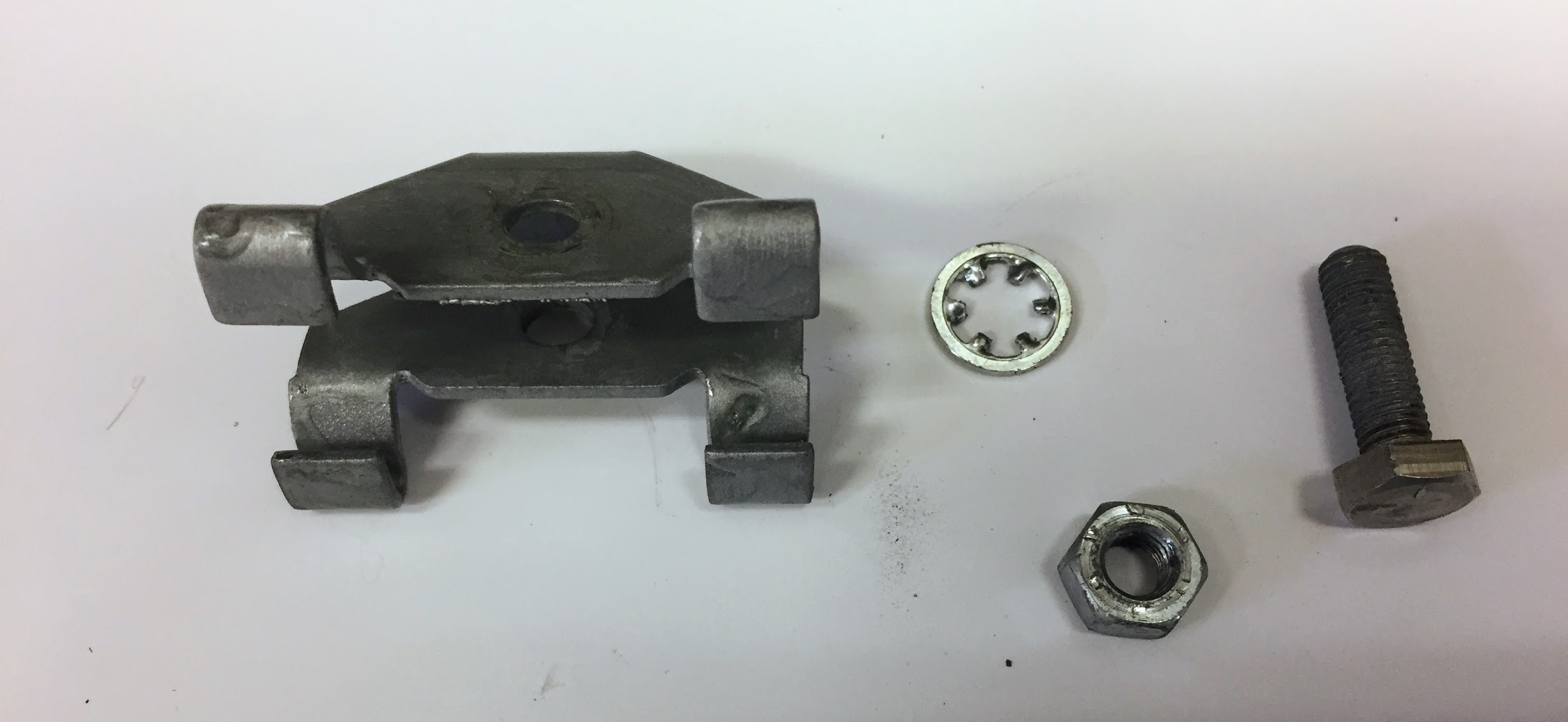
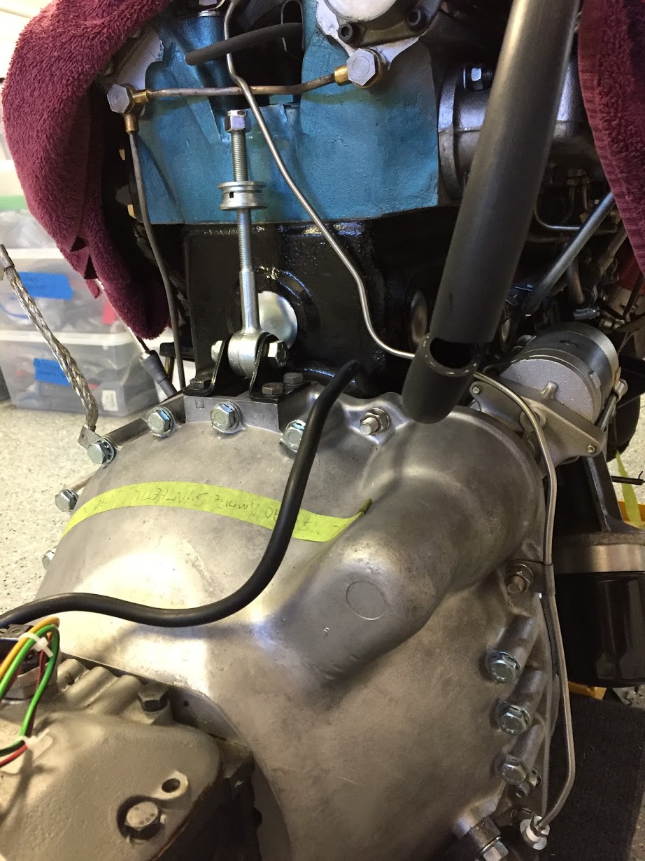
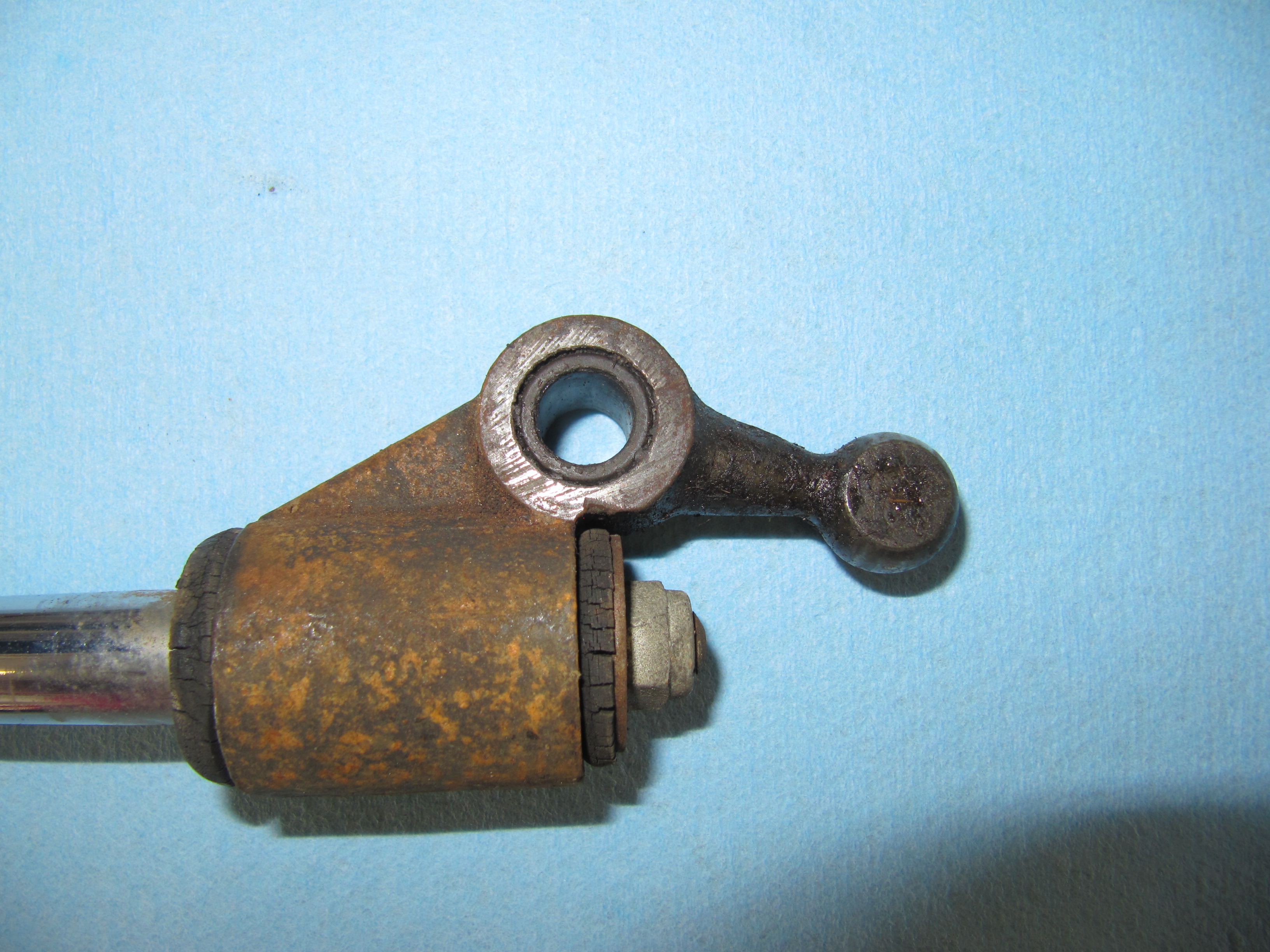
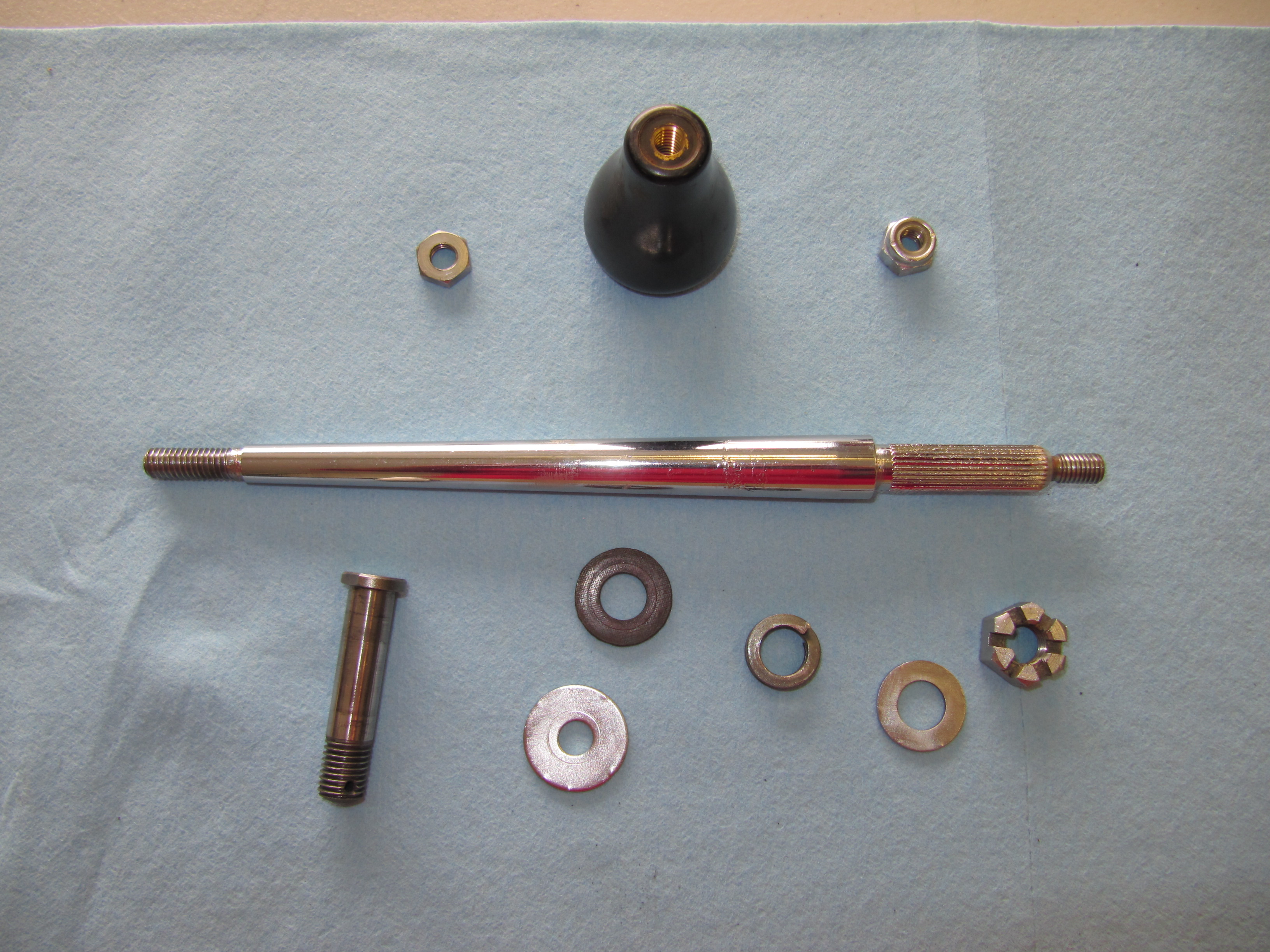
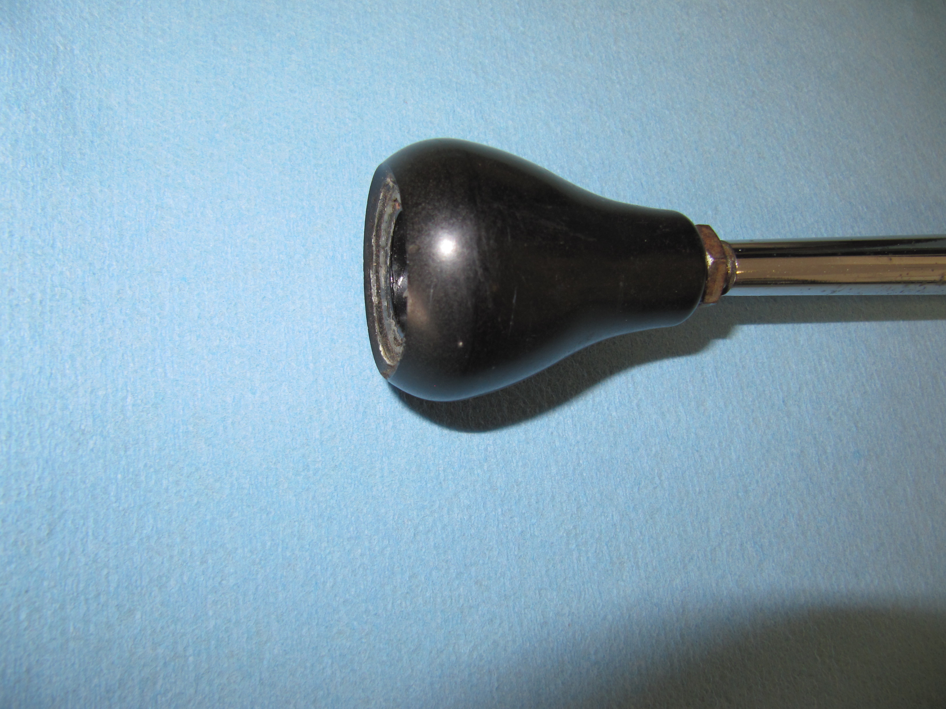
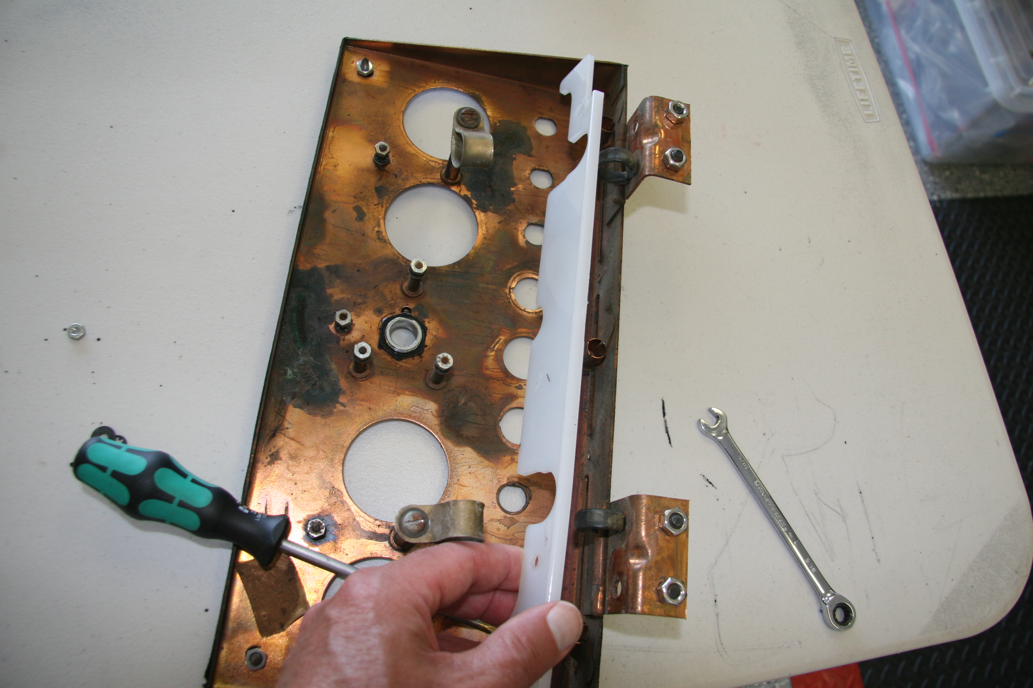
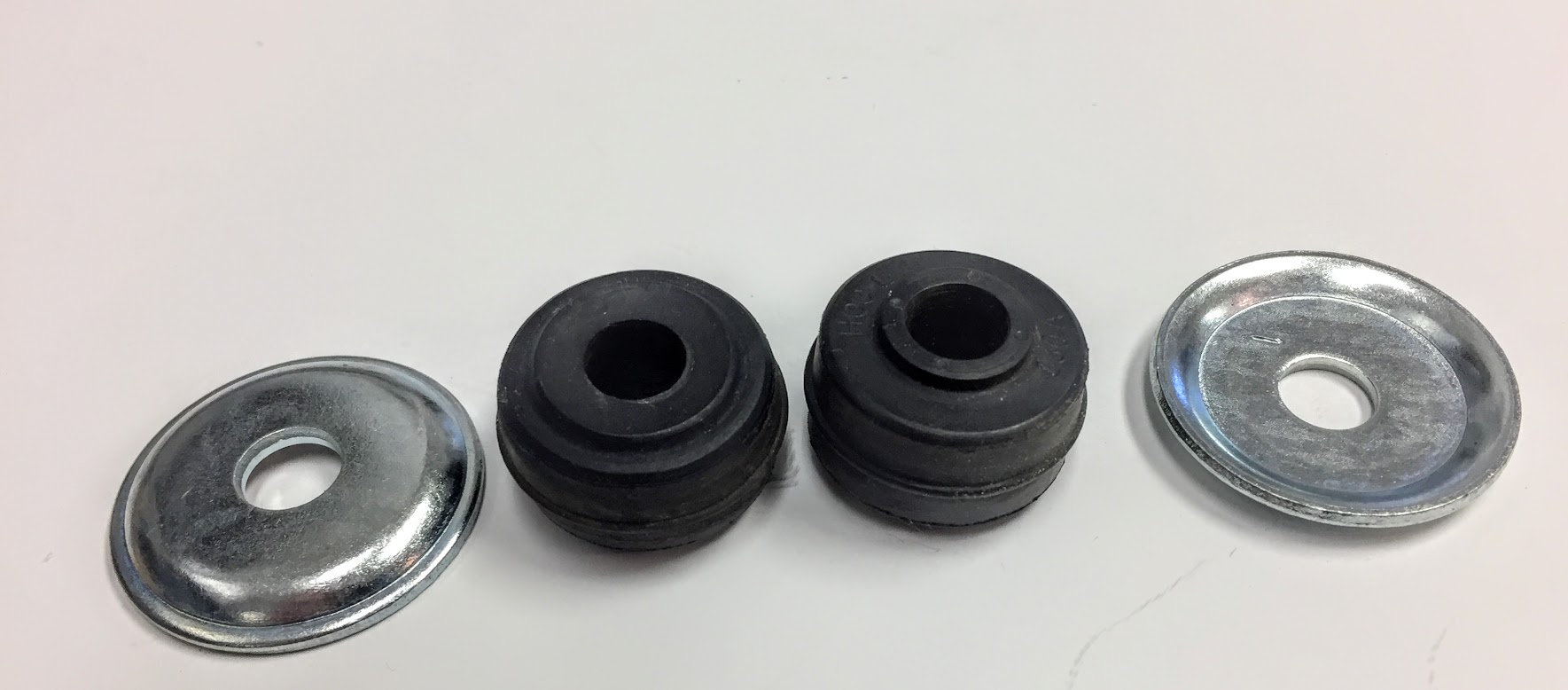
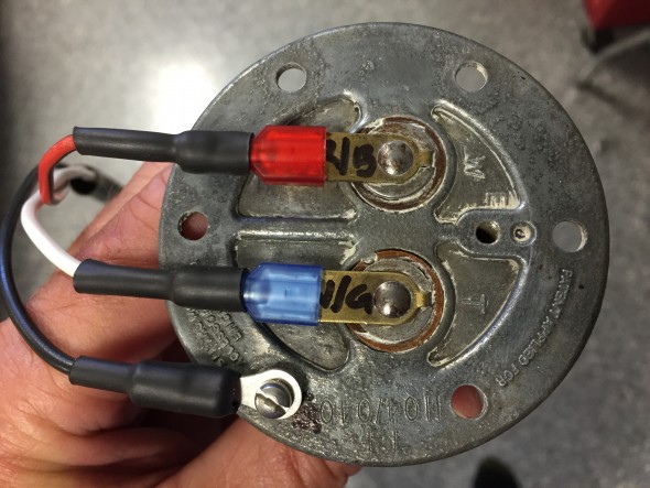
The “Warning Lamp Indicating Handbrake ‘ON’ Position and Level in Brake Fluid Container” is comprised of the cover and window assembly, a spring washer on the central terminal post, with nuts and washers. Rubber sleeves are slipped over the white wire at the terminal and the white and red/green wires are contained together in a rubber sleeve of about 4.” The warning light was cleaned and reassembled and a new face plate was installed.

Warning Lamp
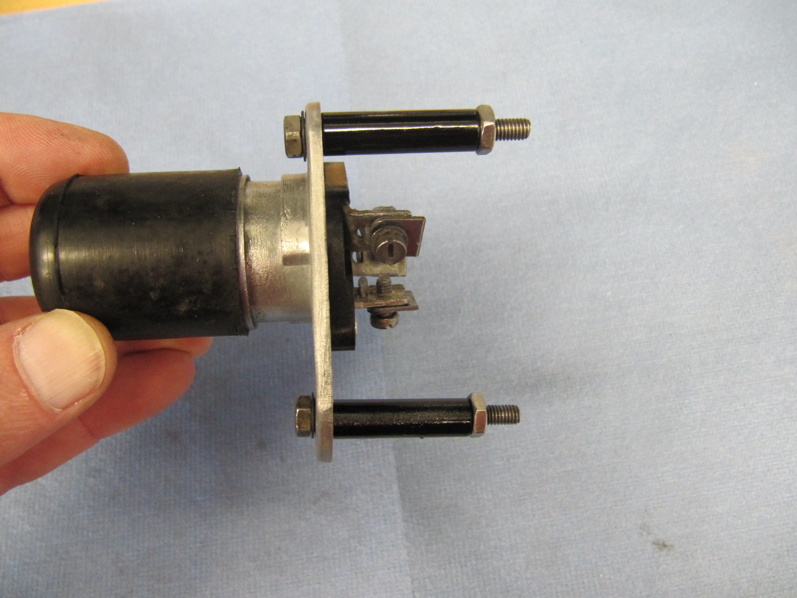
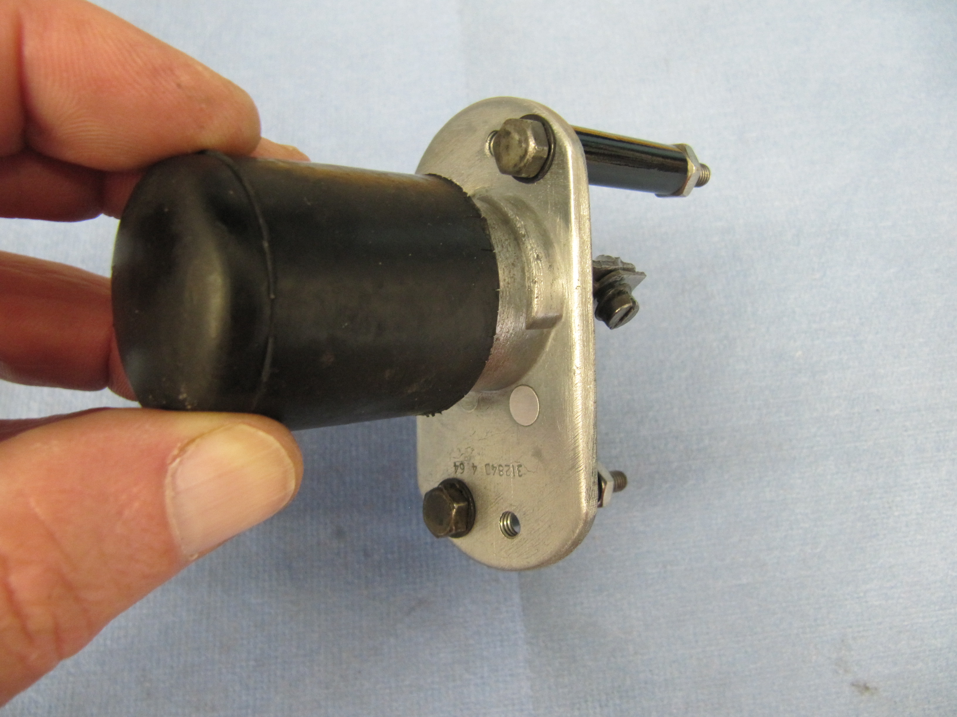
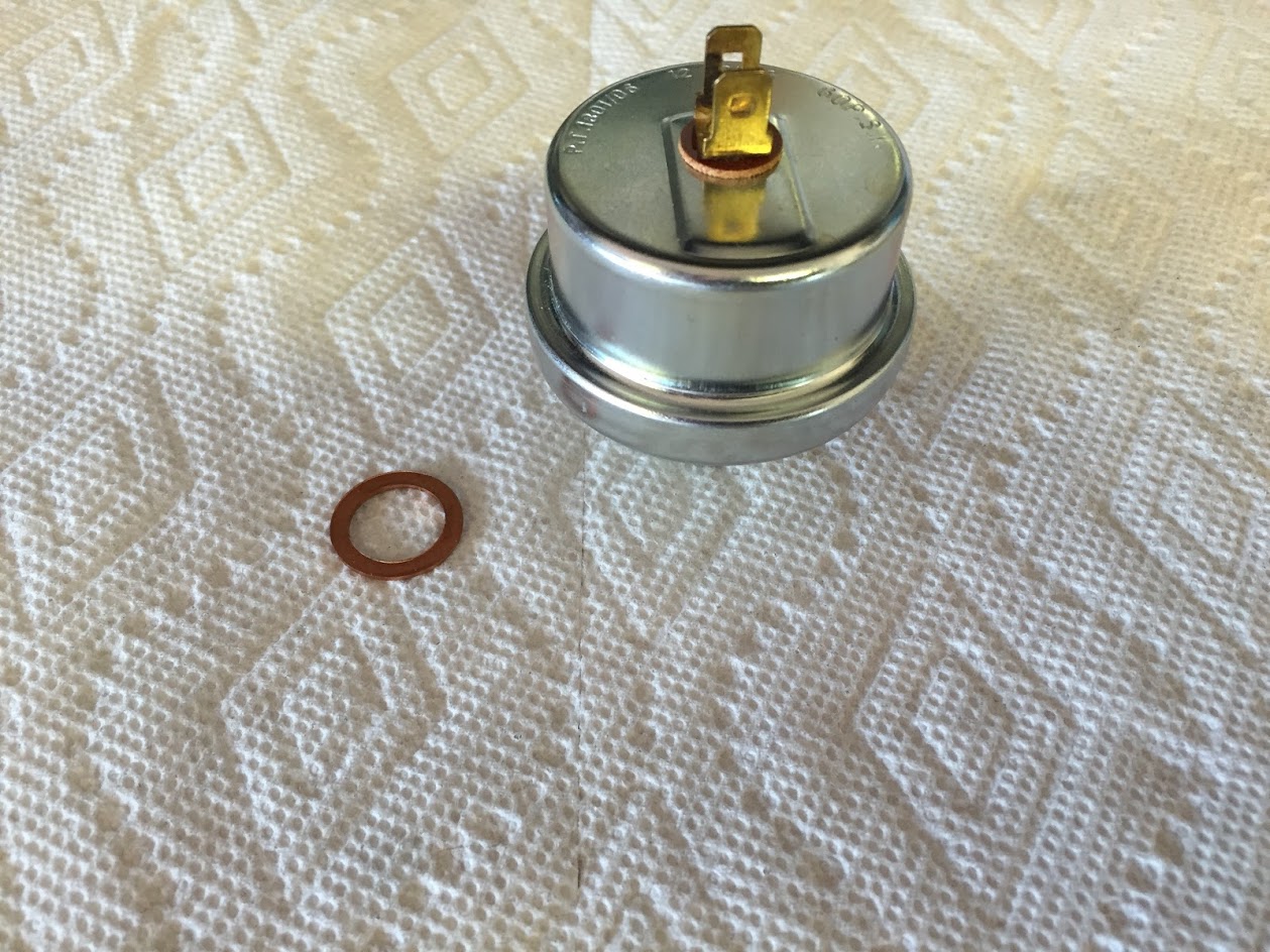
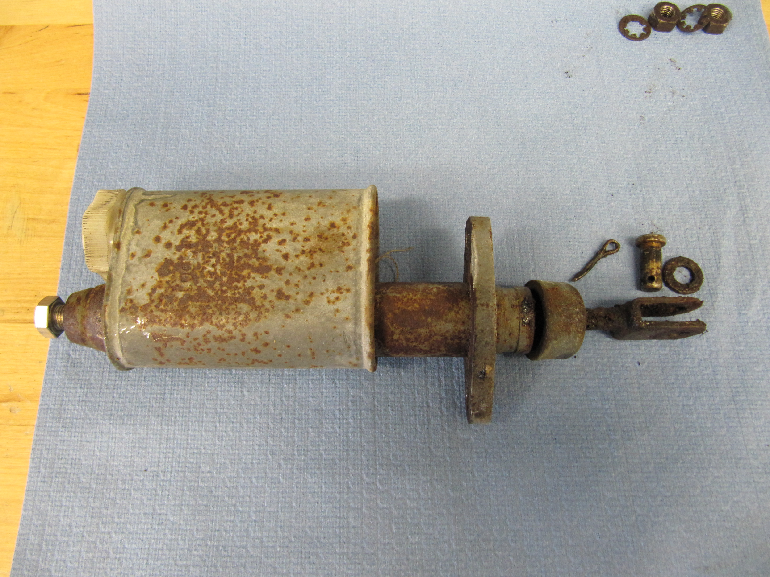
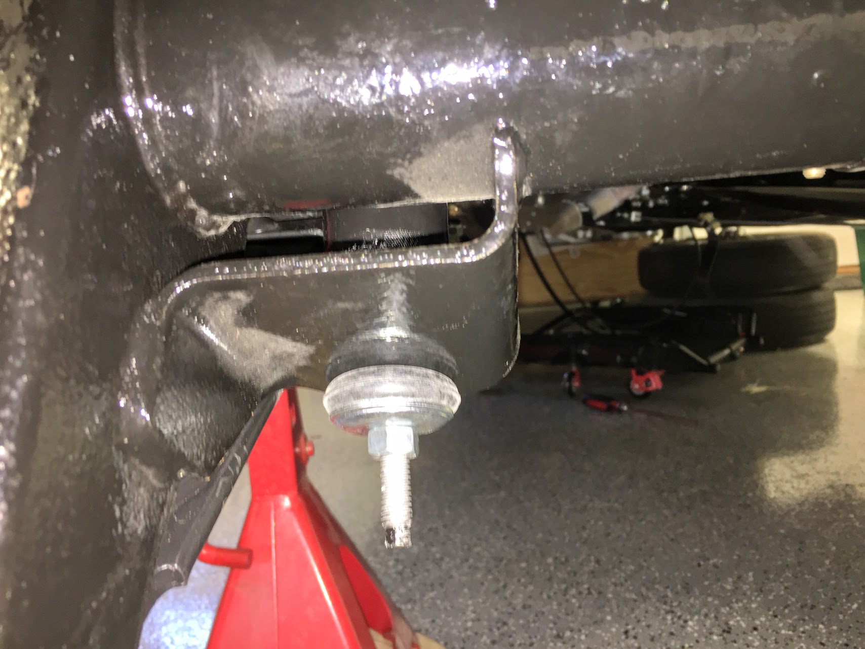
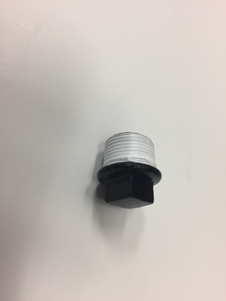
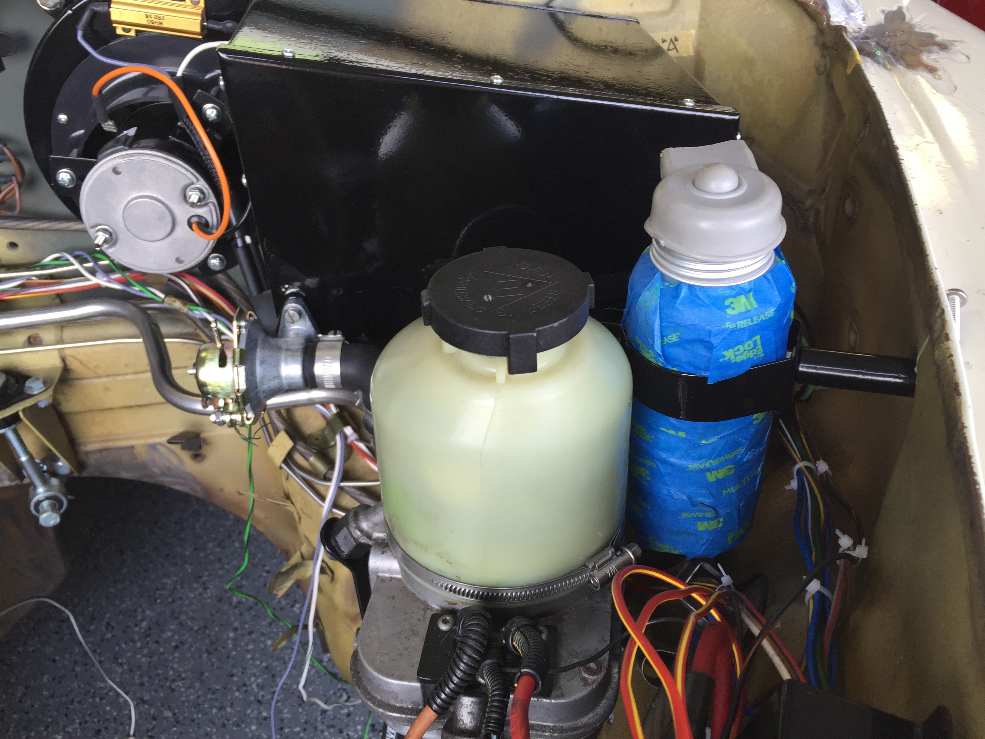
Hydraulic Fluid Reservoir, Low Fluid Warning Switch
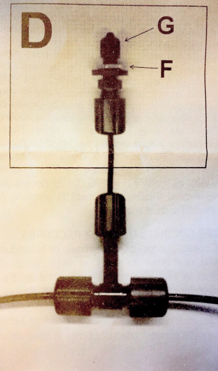
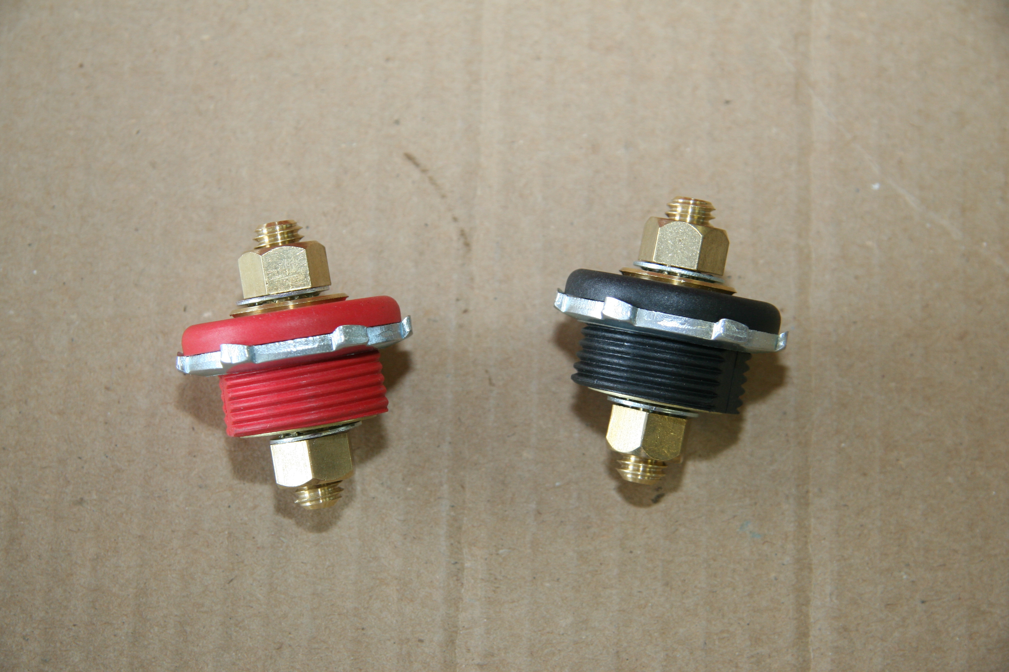
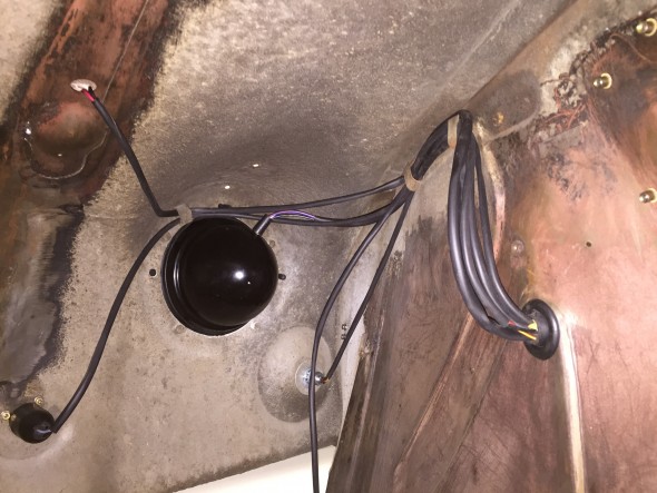
The fluid canister contains a float activated level indicator switch in its screw cap.

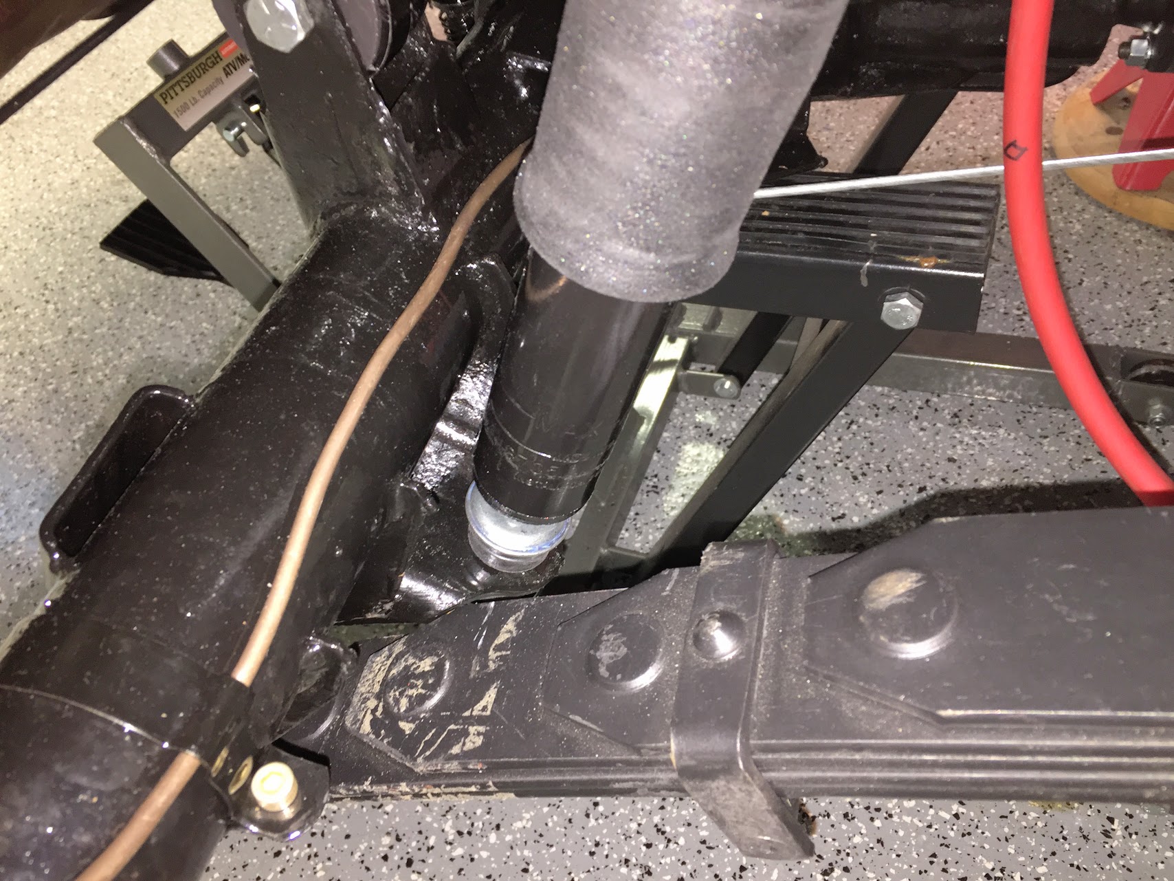
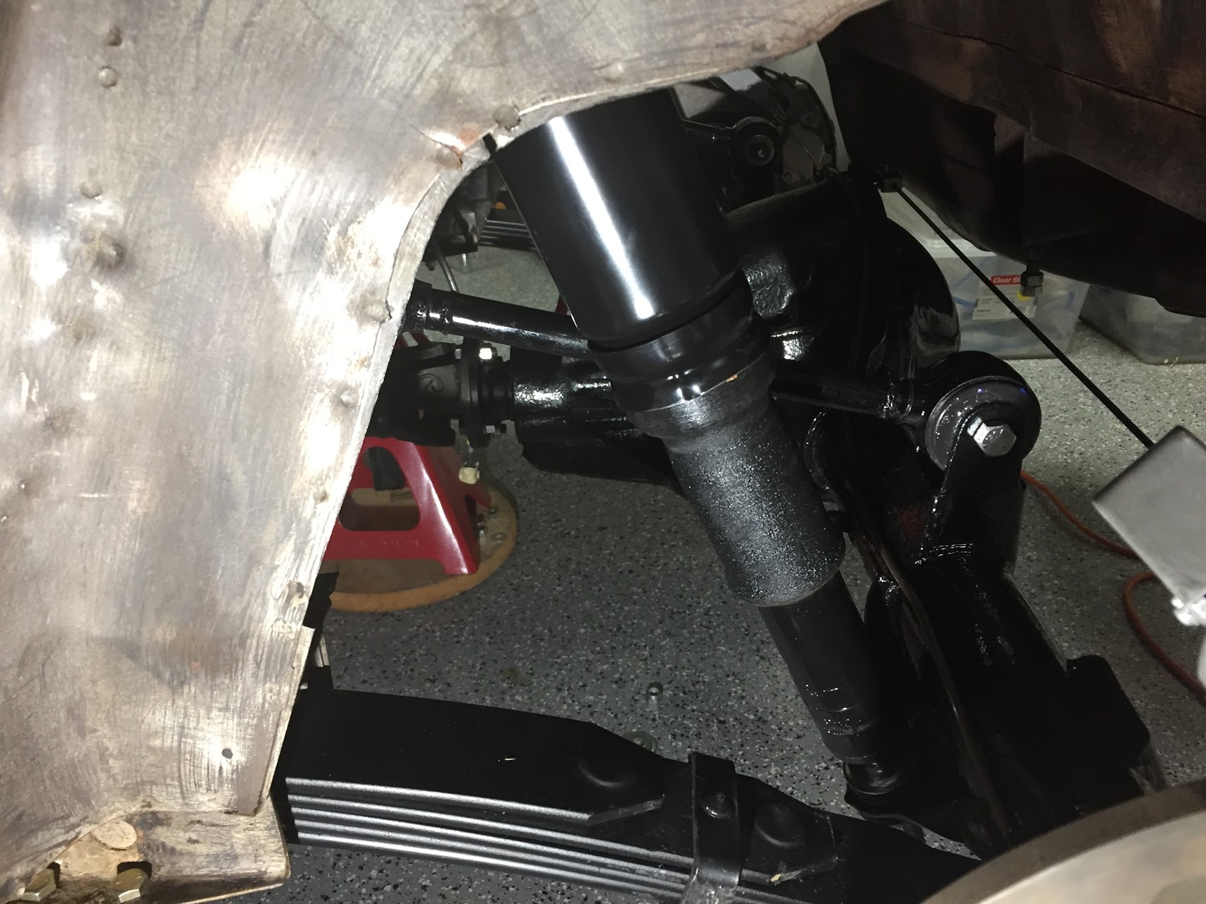
Hydraulic Fluid Container Location
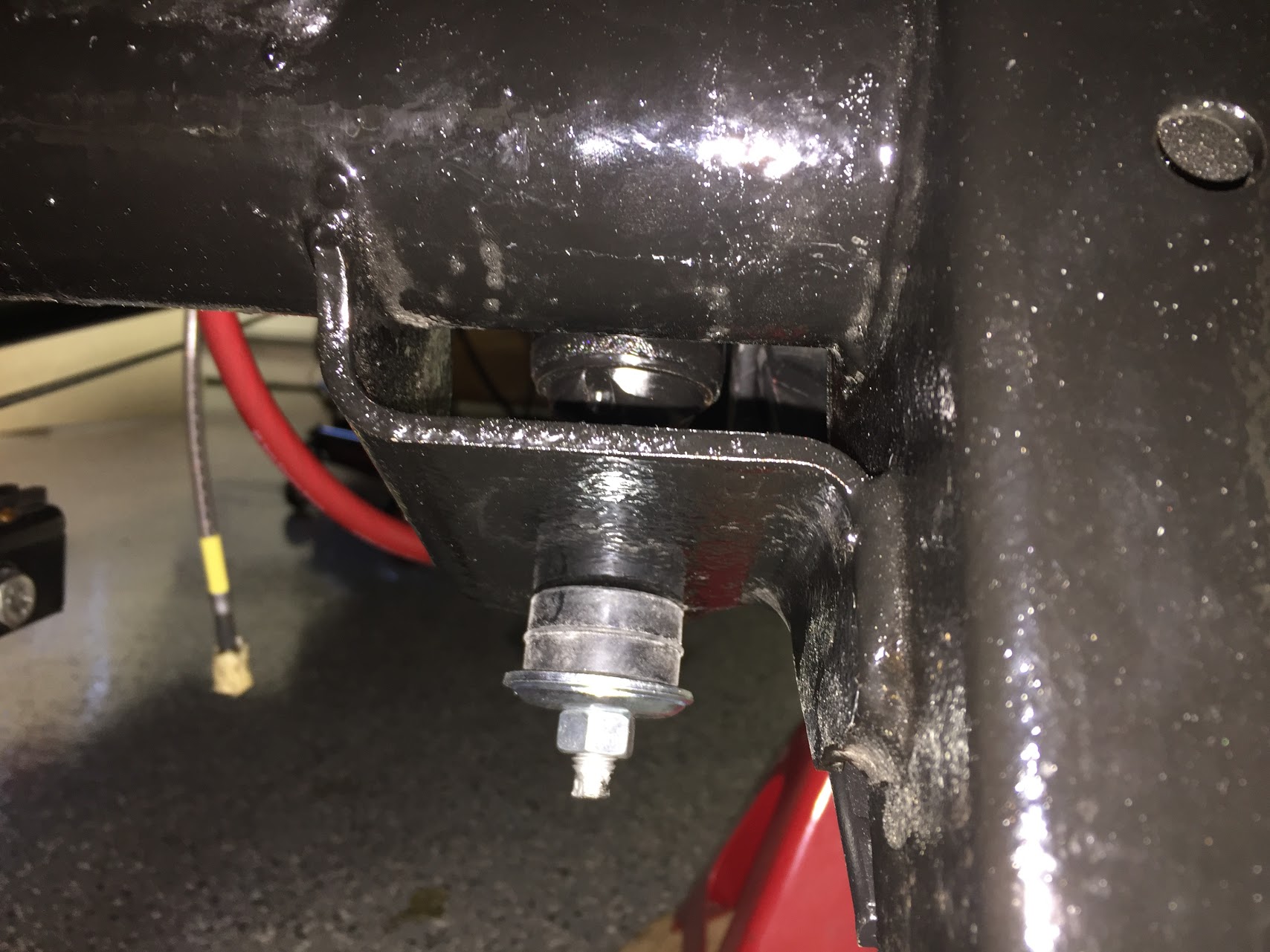
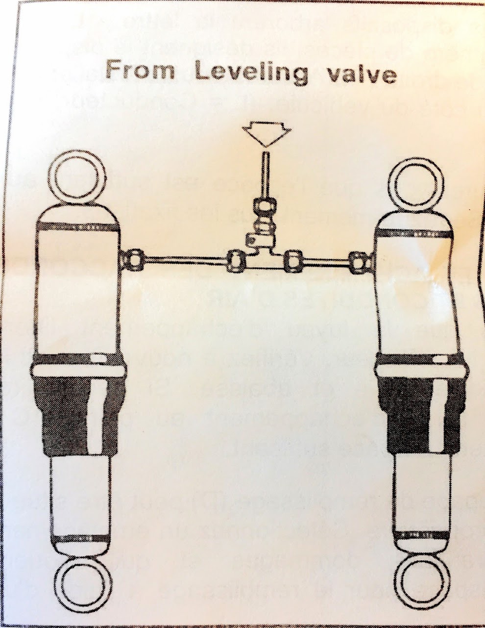
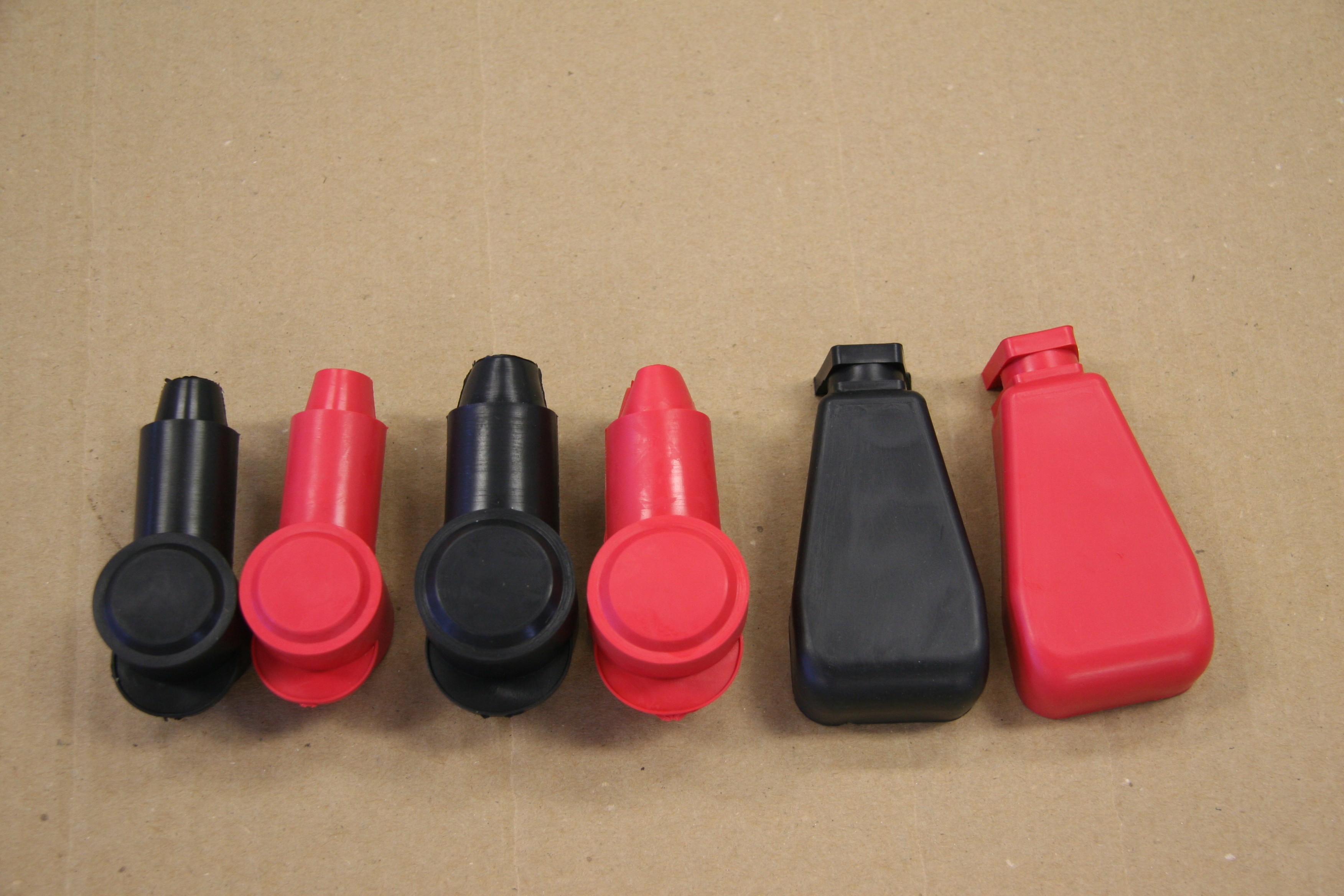
Two wires attach the switch with spade connectors and are protected by a rubber cap over the indicator plunger. I sourced a new canister and indicator switch (cap) from SNG Barratt. The canister is covered in blue painter’s tape just to keep it clean during the restoration build. I was able to reuse the original rubber protective cap. An 18AWG light green wire is connected to one terminal. This wire joins via a 4 way snap connector with an orange 18 AWG wire from the handbrake switch. A single orange 18 AWG wire then connects to the LH Barrier Block Terminal #5B. A dark green wire from LH Barrier Block #5A connects to a 2 way snap connector with a red/green wire on the dash warning light pigtail.
A black 14 AWG wire connects to the other level indicator switch terminal and provides a ground connection to the chassis.
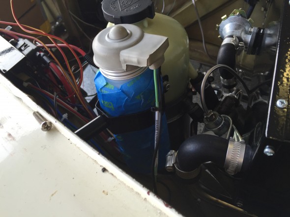
Hydraulic Fluid Container Wiring