Headlamps
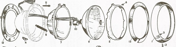
Headlamp Schematic
Cars exported to the USA all had sealed beam headlights.
Headlamp
Mounting and Adjusting Screws
Four #10 – 32 x 1/2″ slotted cheese head screws with flat and shakeproof washers fasten the lamp assembly to the car’s body. The rubber seal is located between the body and the lamp bowl. Their location is shown in the Lamp Diagram.

Headlamp Complete

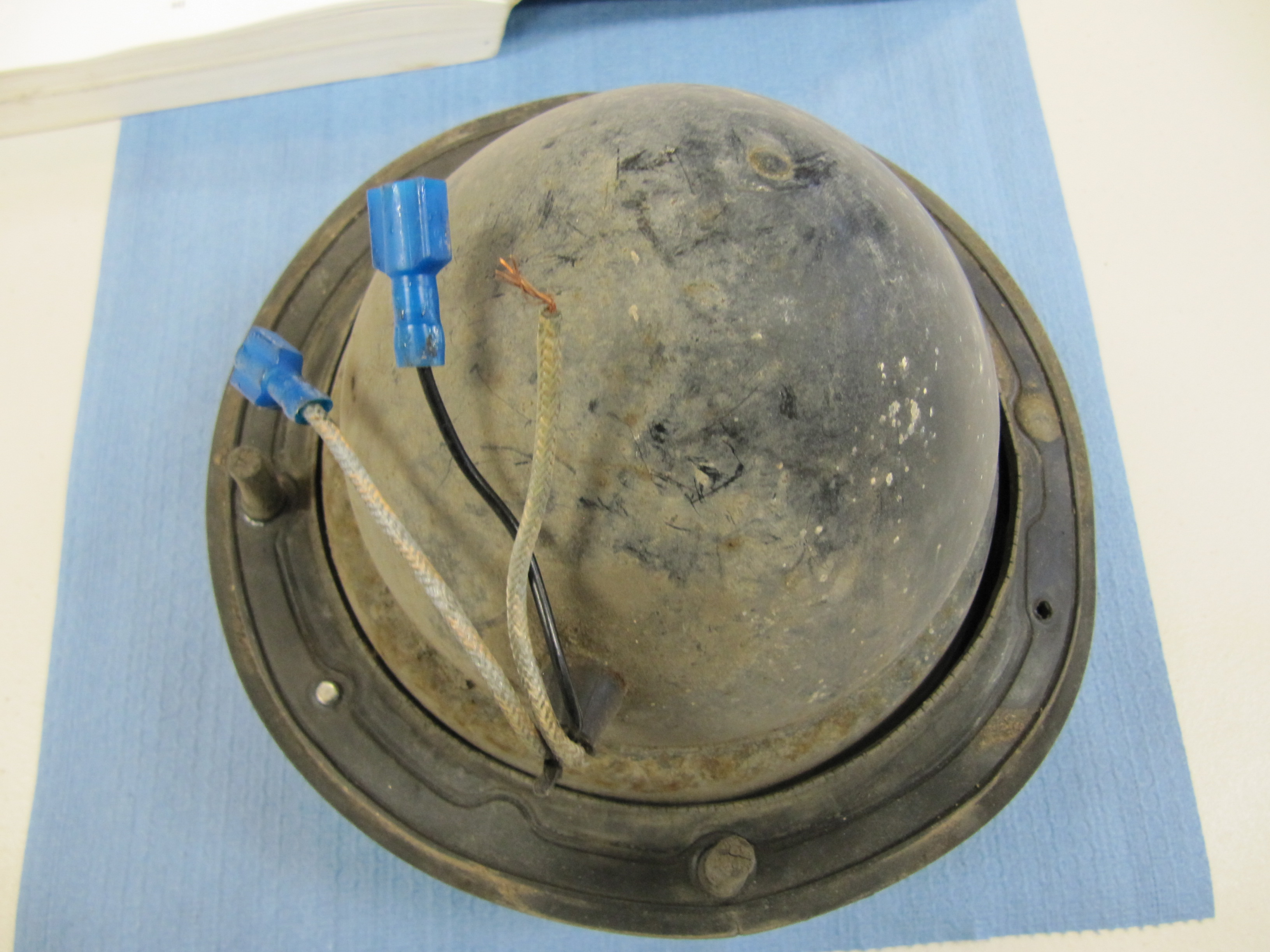
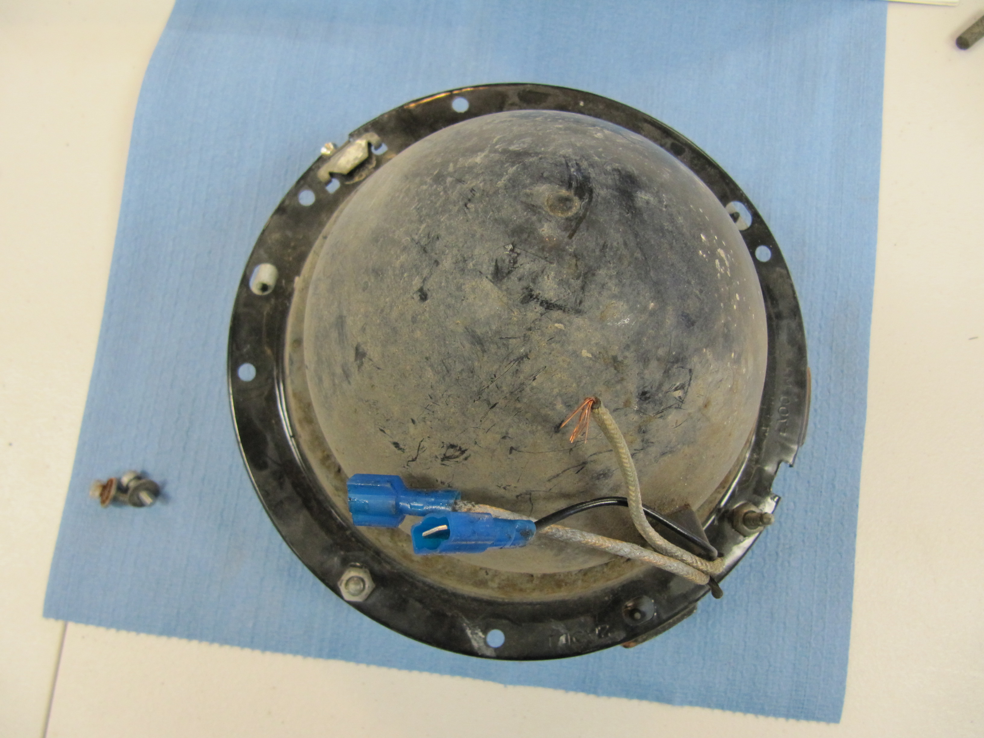
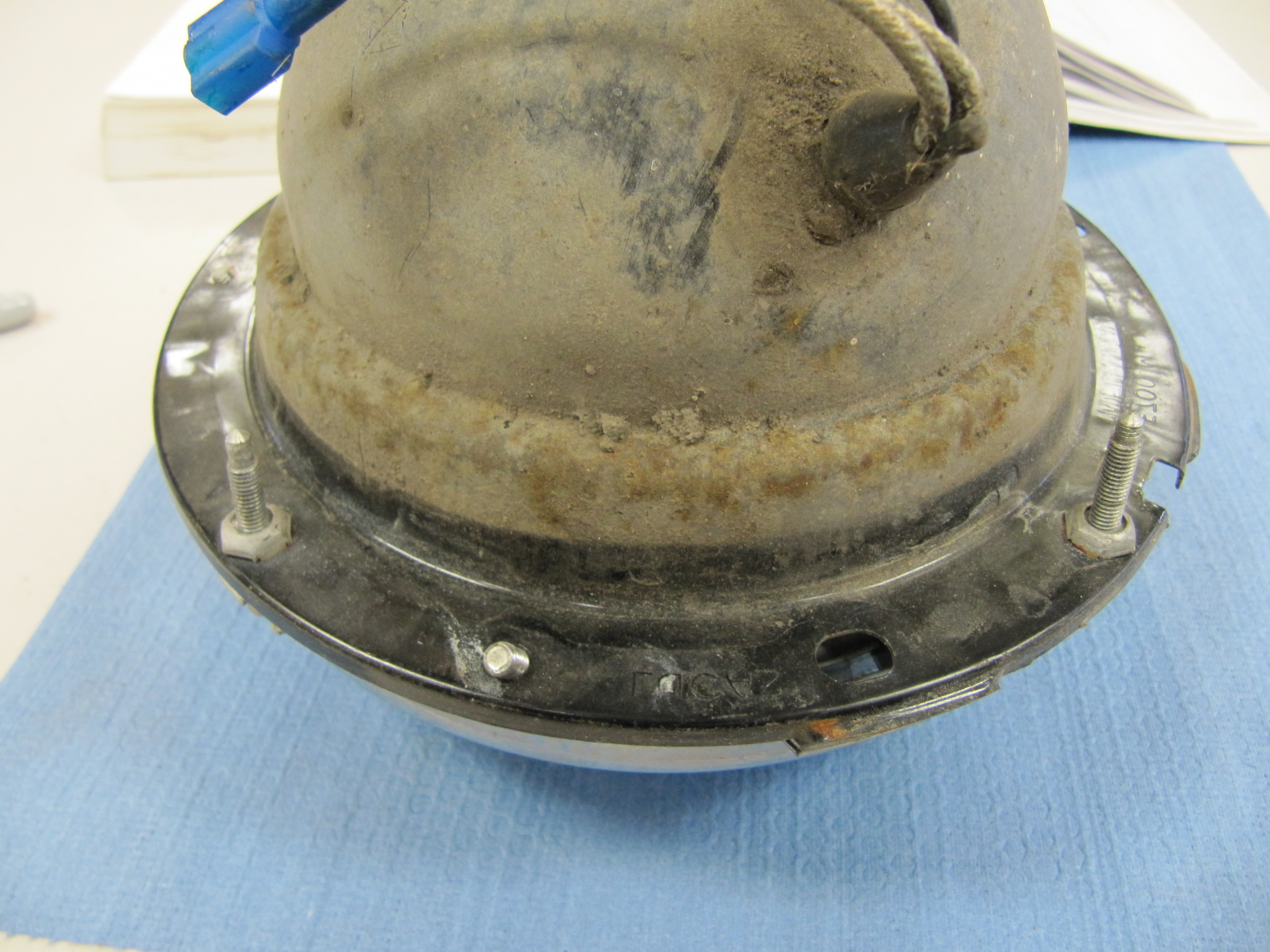
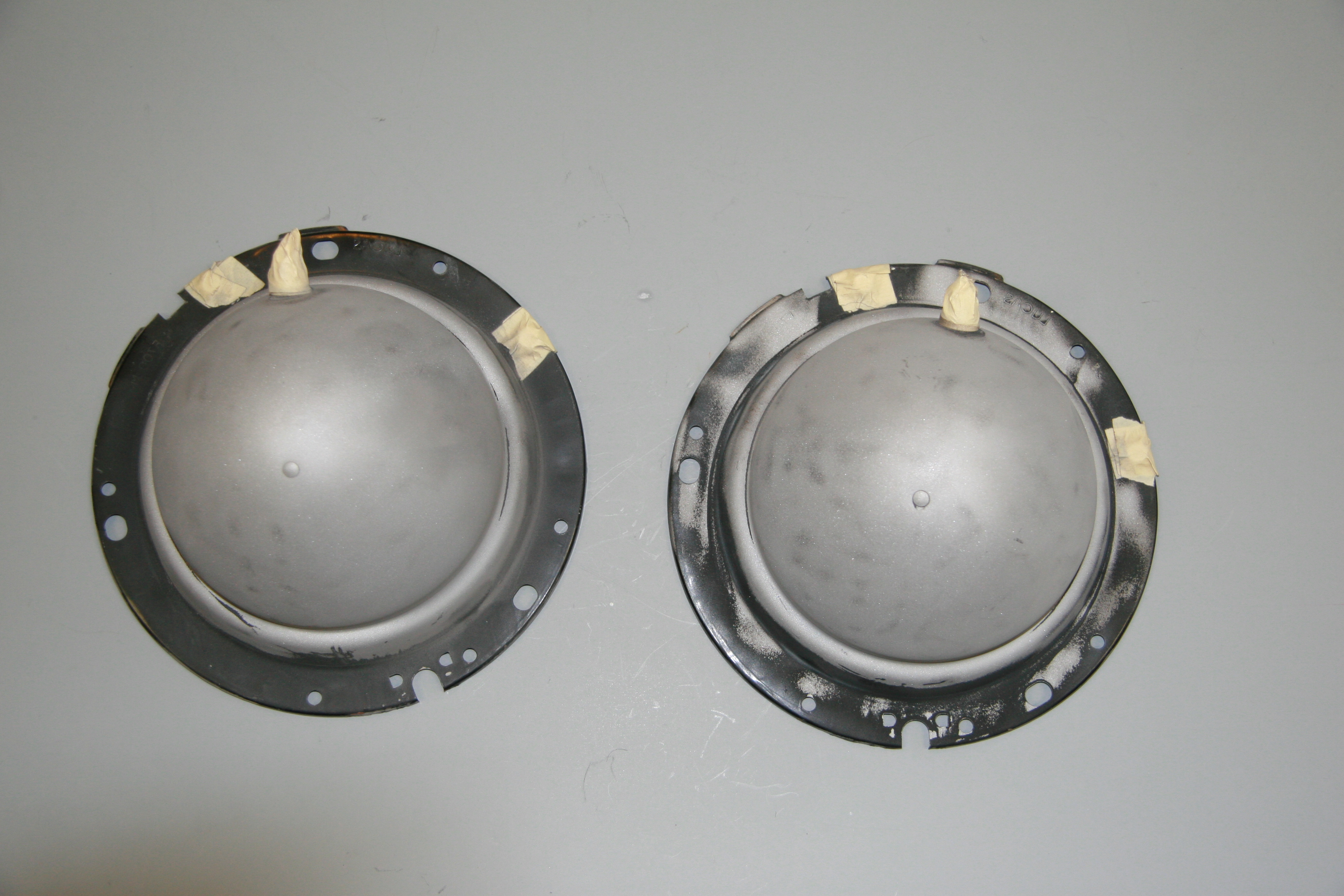
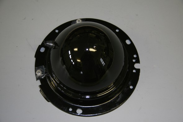
Headlamp Bowl
Headlamp Seal
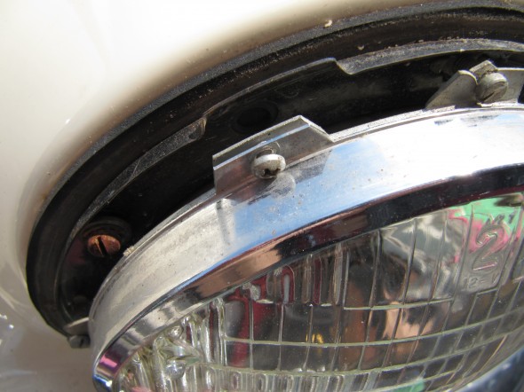
Two special trimmer screws are used to adjust the bulb setting. These are located at roughly 9 o’clock and 1 o’clock as seen in the diagram.

Trimmer Screws
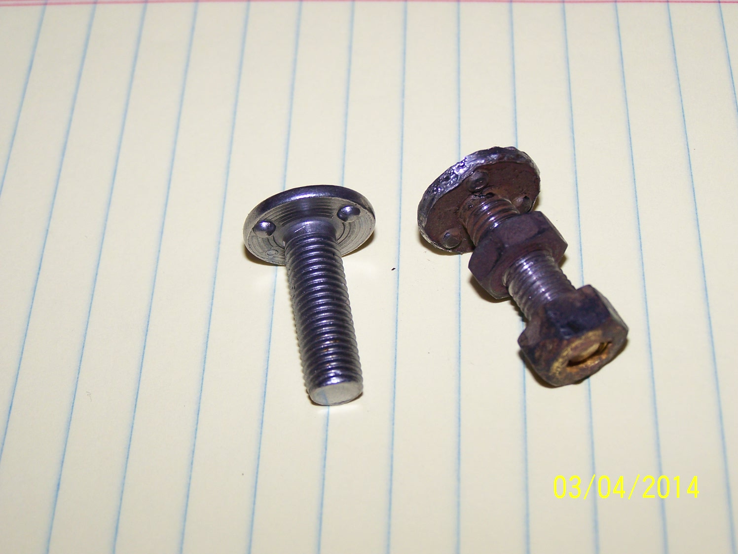
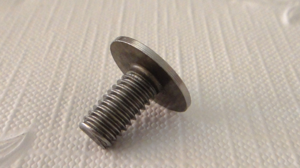
A chrome #8 slotted self tapping screw is removed from the spire nut at the bottom of the lamp to free the outer chrome trim ring.
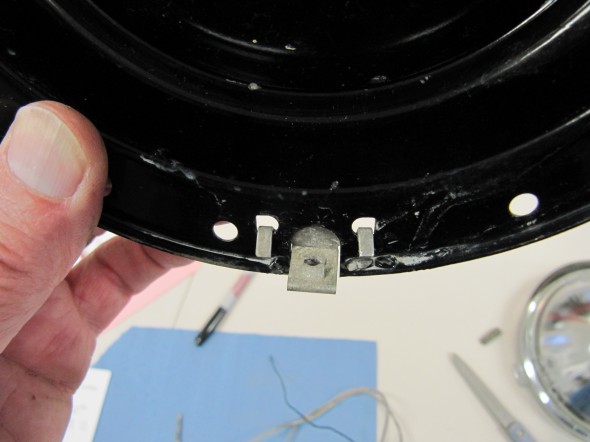
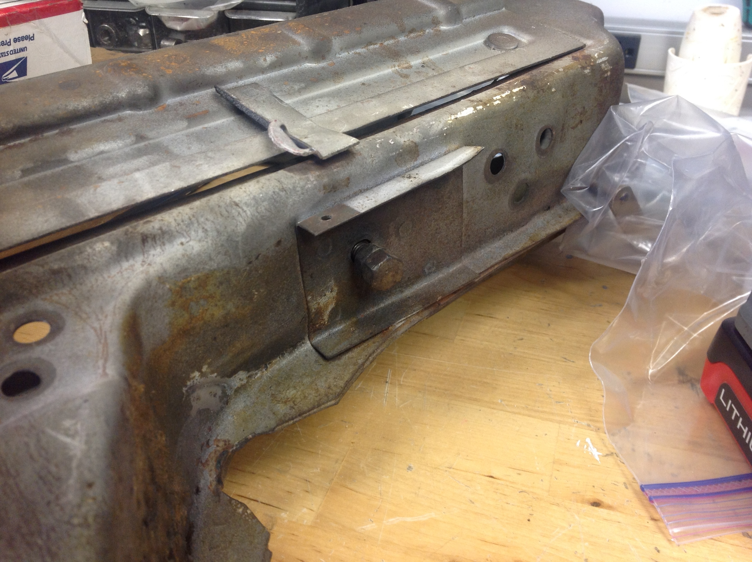
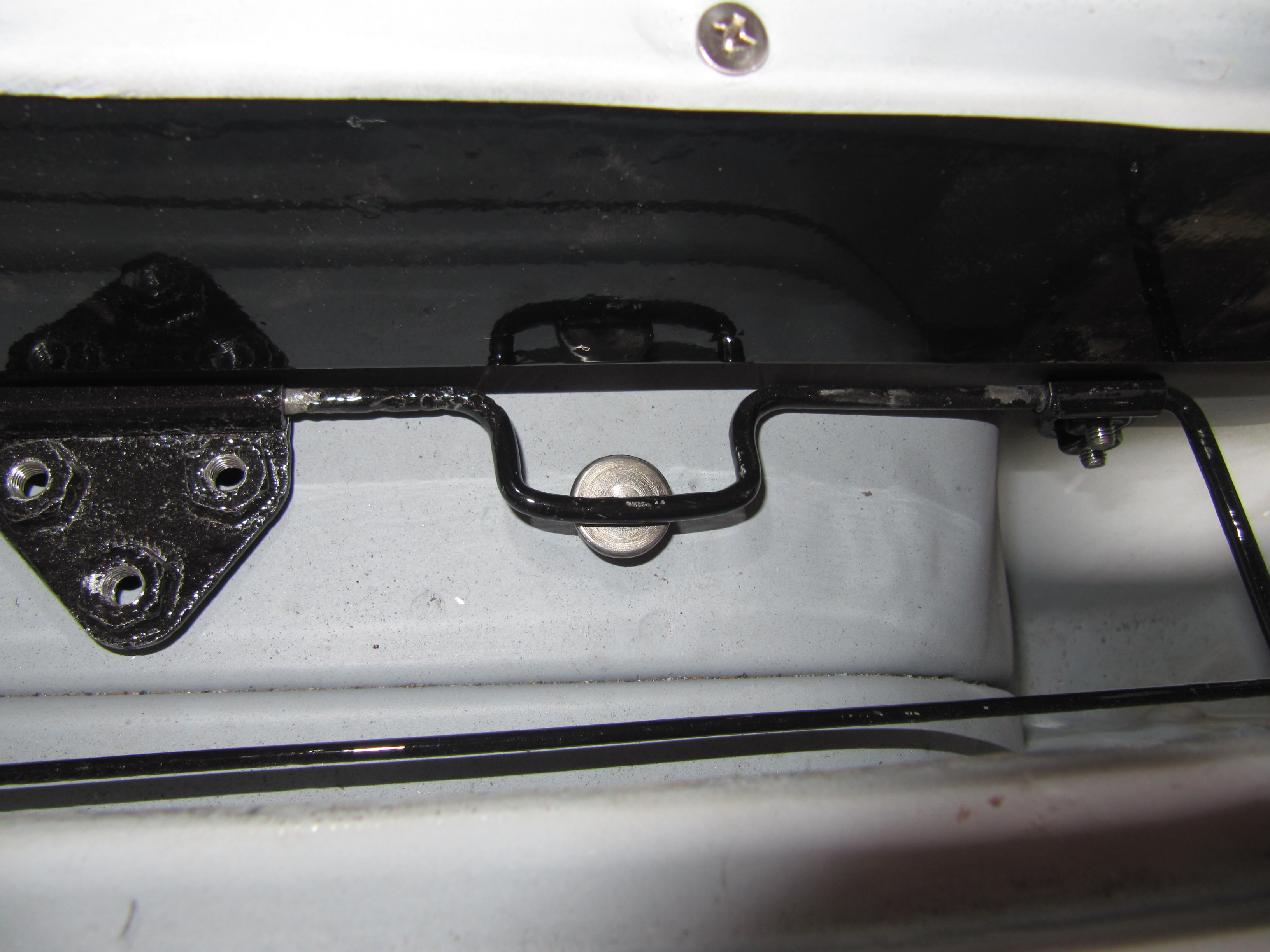
Spire Nut
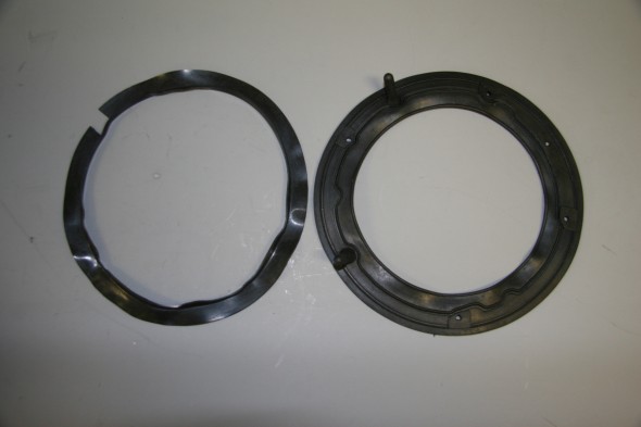
Three #6 phillips head screws fasten together the chrome retaining ring and the galvanized unit seating rim . These screws are located at 11, 7, and 2 o’clock. They align with the oblong holes in the lamp bowl.
Headlamp Rims
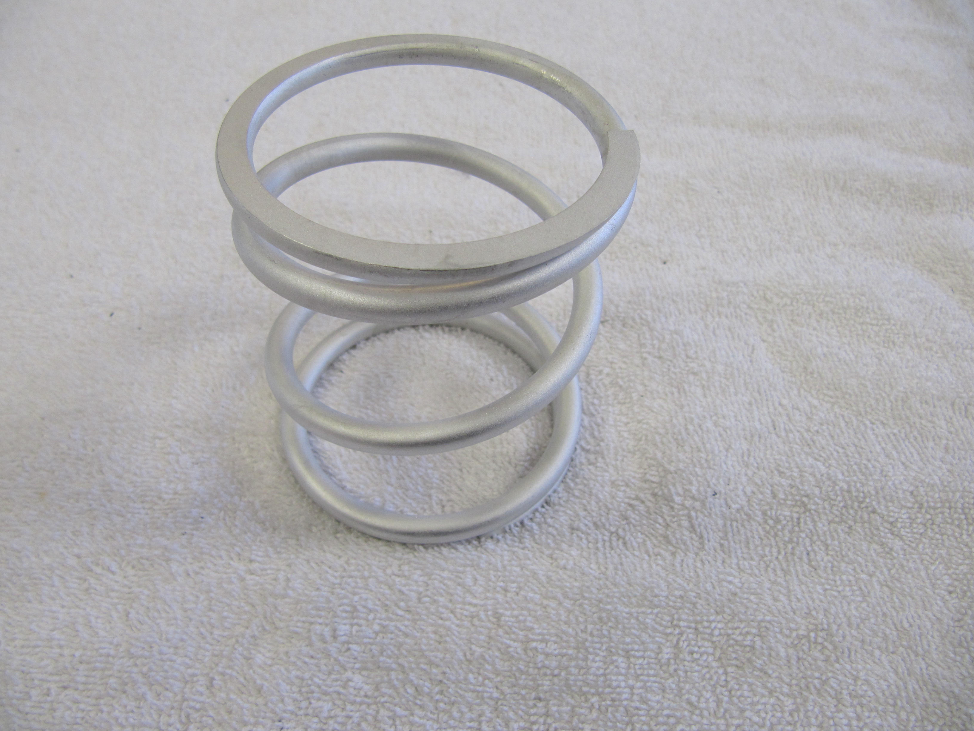
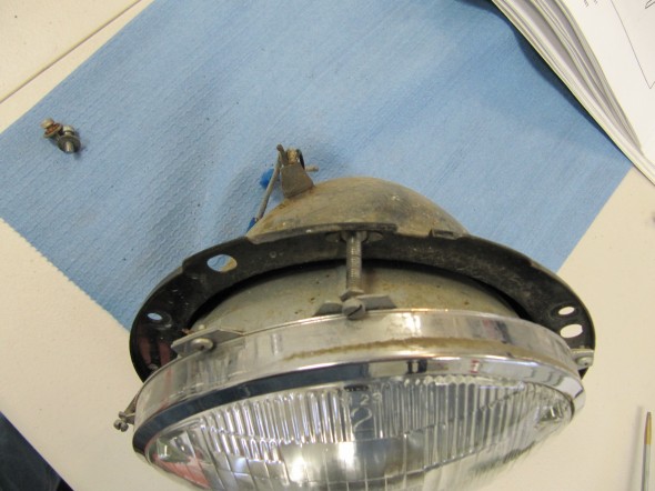
The seating rim is held to the bowl with a Spring, Fixing Unit Seating Rim.
The bulb adaptor wiring sits behind the bulb and its wiring feeds through the rubber seal in the back of the bucket. New plug adapters were sourced from British Wiring and all the wiring was replaced with new.
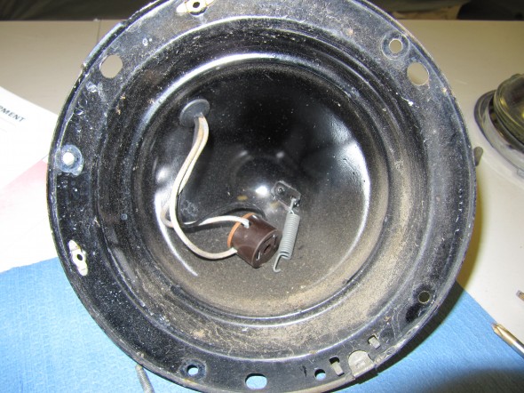
Sealed Beam Unit Adaptor and Bulb Retaining Spring

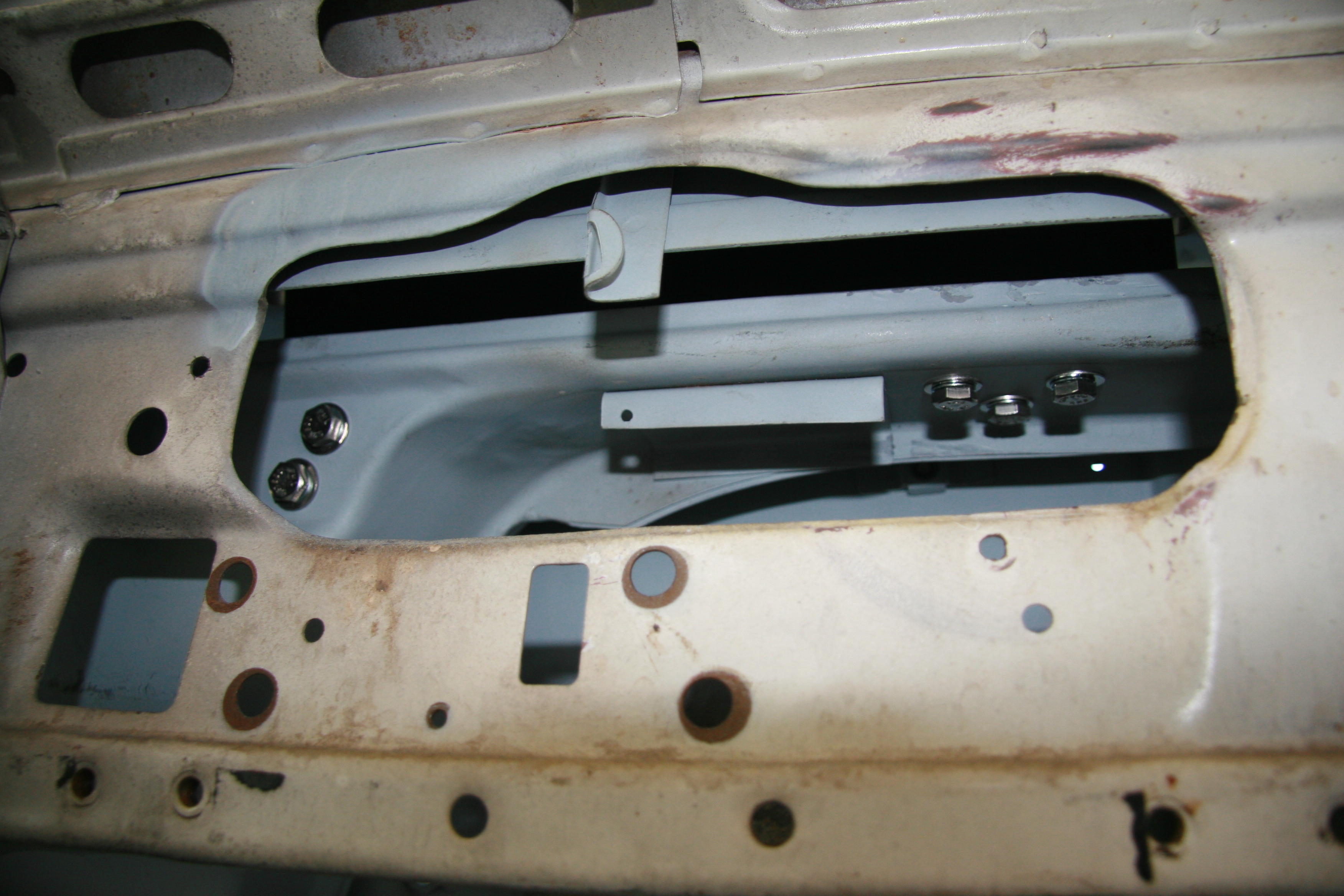
Headlamp Buckets Ready to Paint
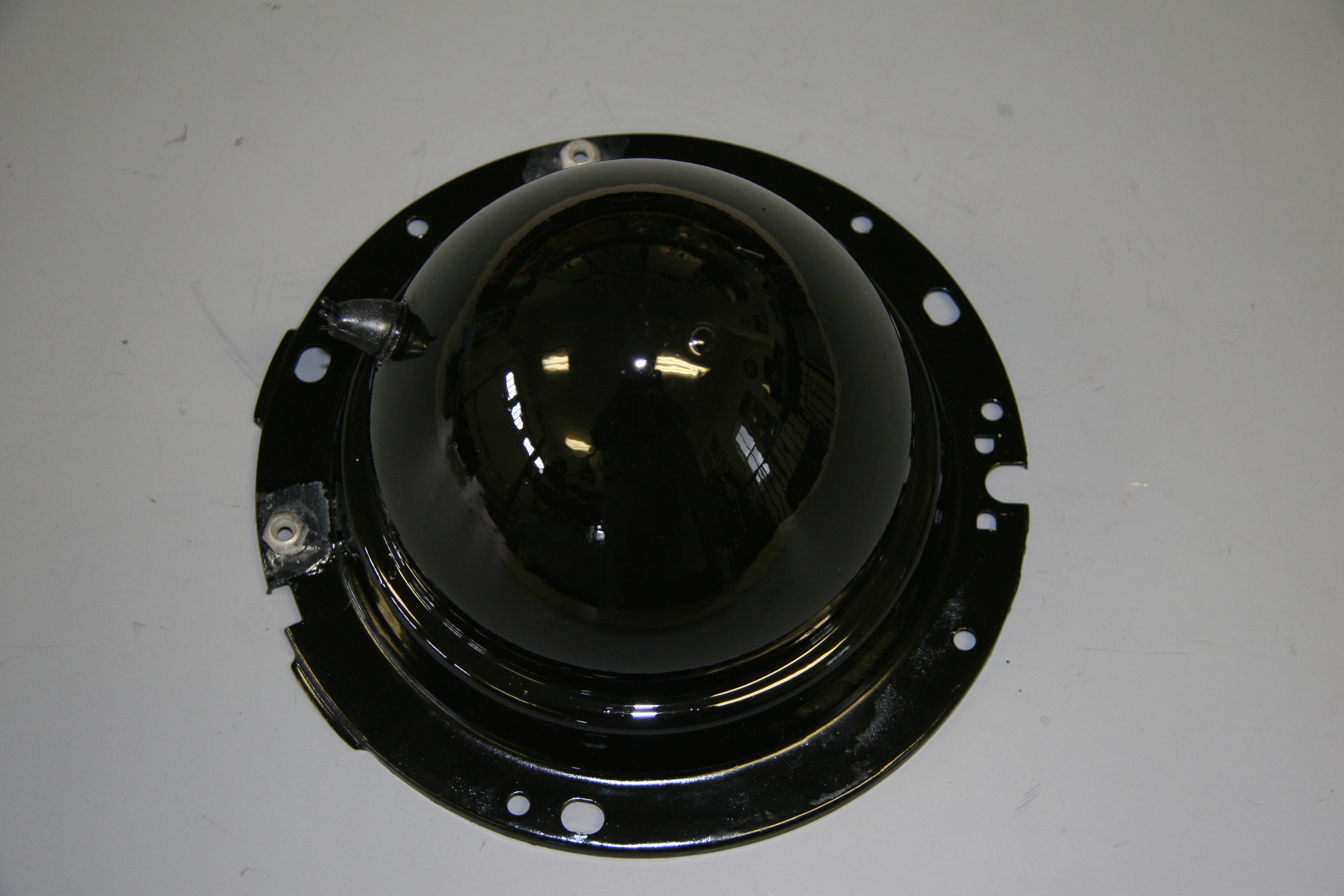
Painted Headlamp Bucket
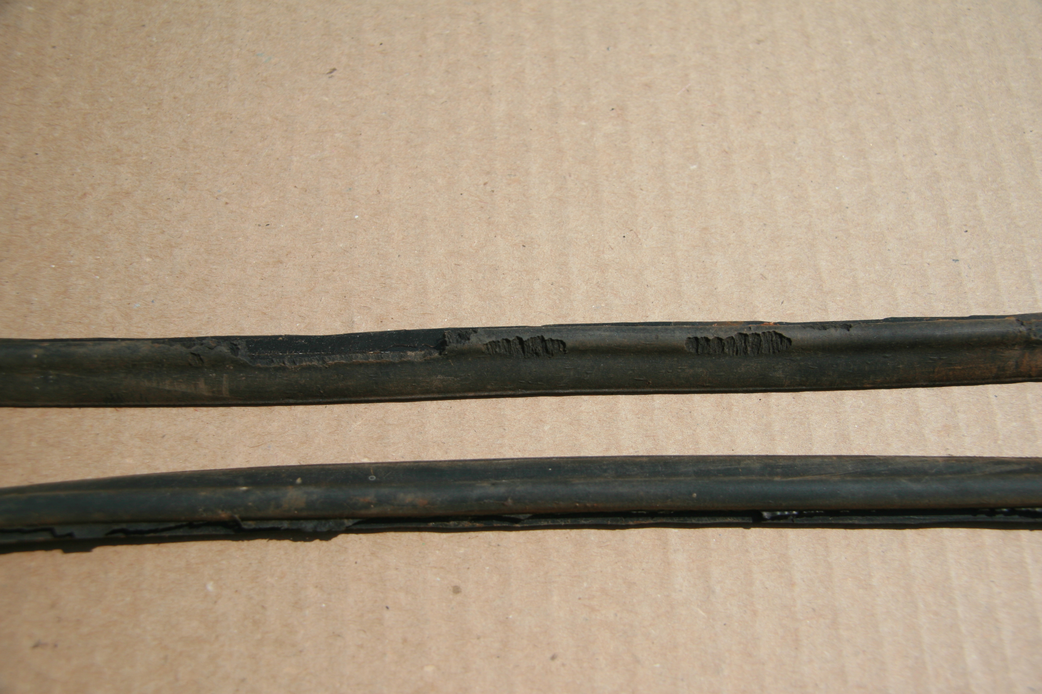
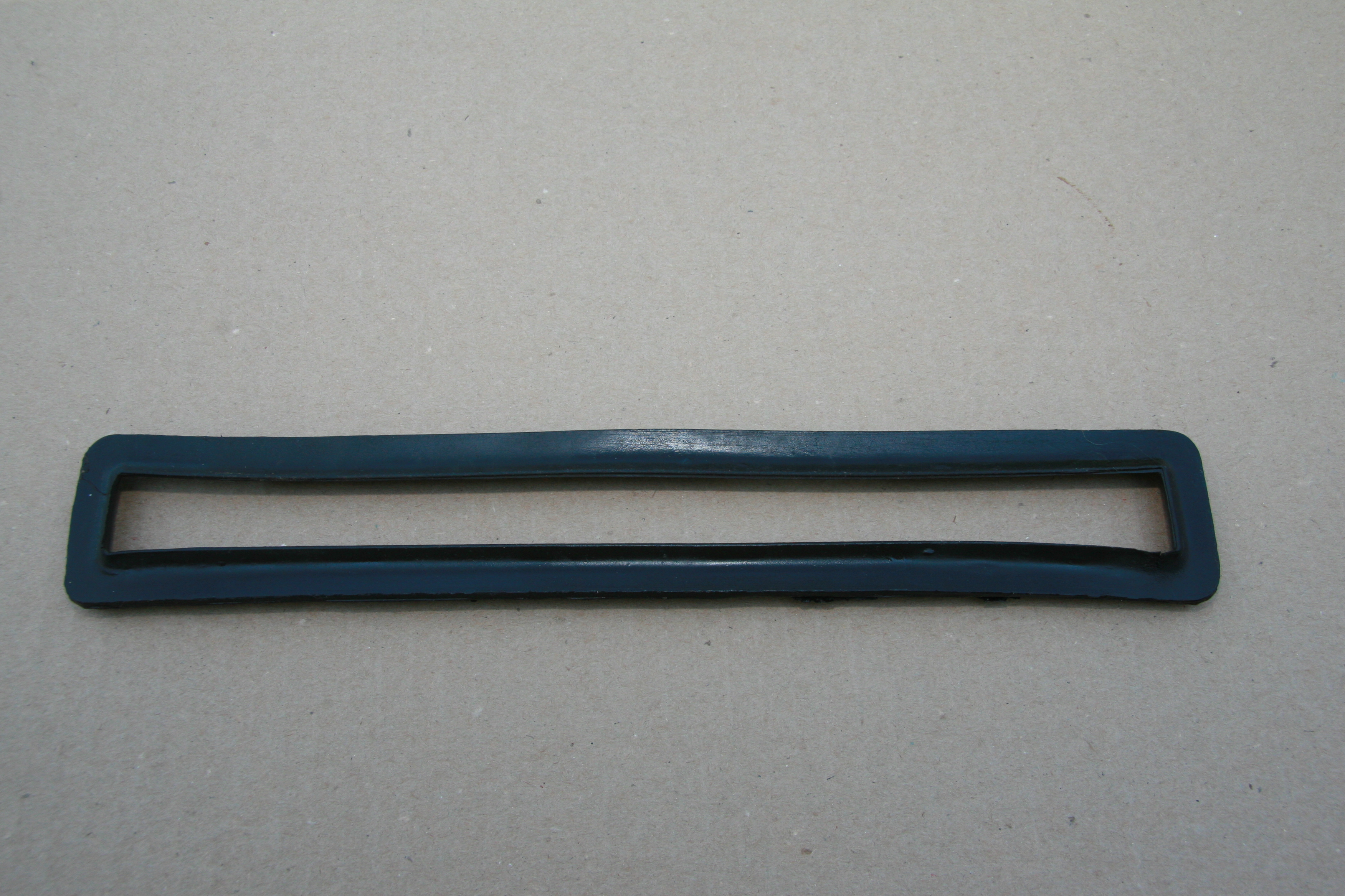
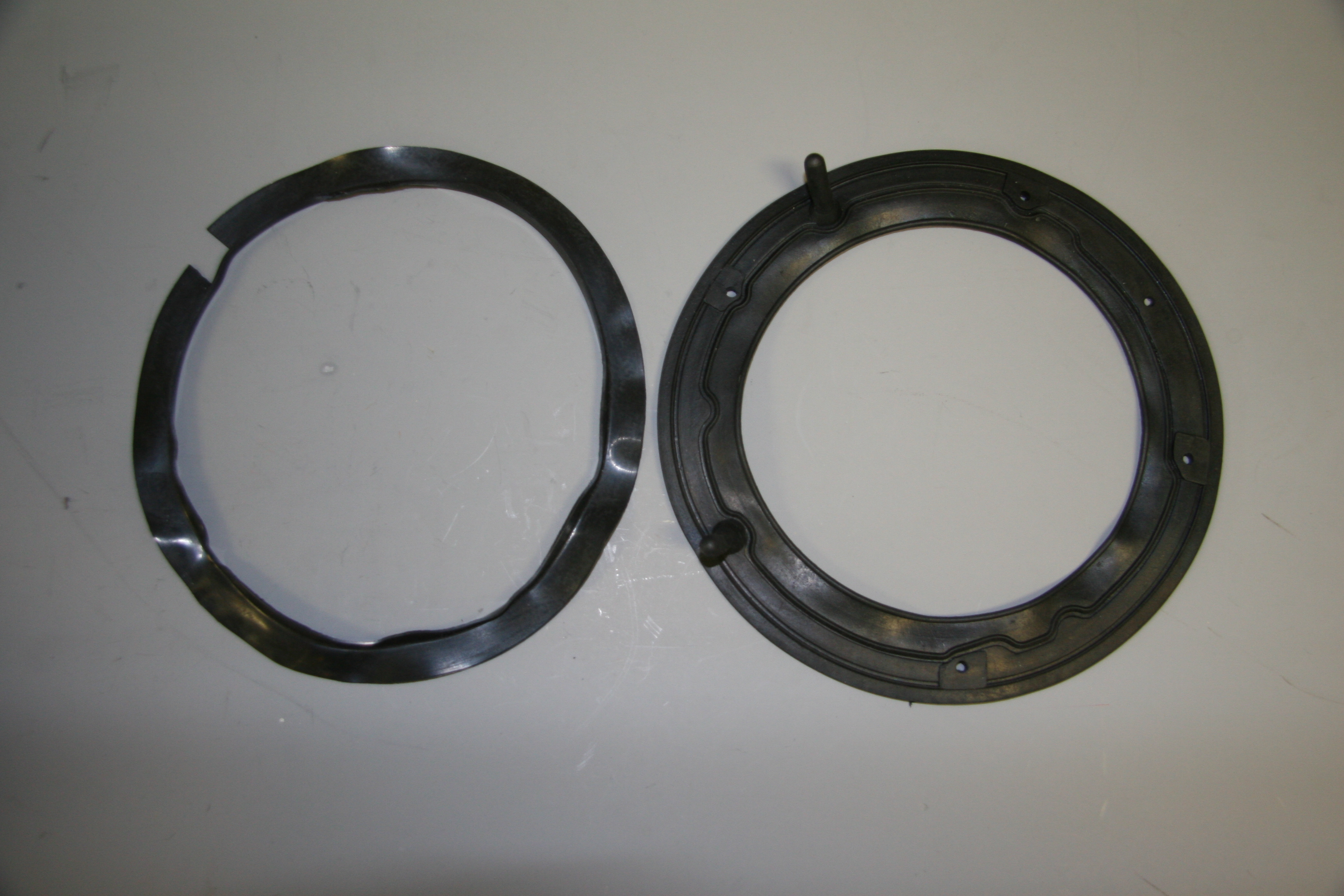
Dust Excluder behind headlight Outer Rim and Headlamp Body Gasket
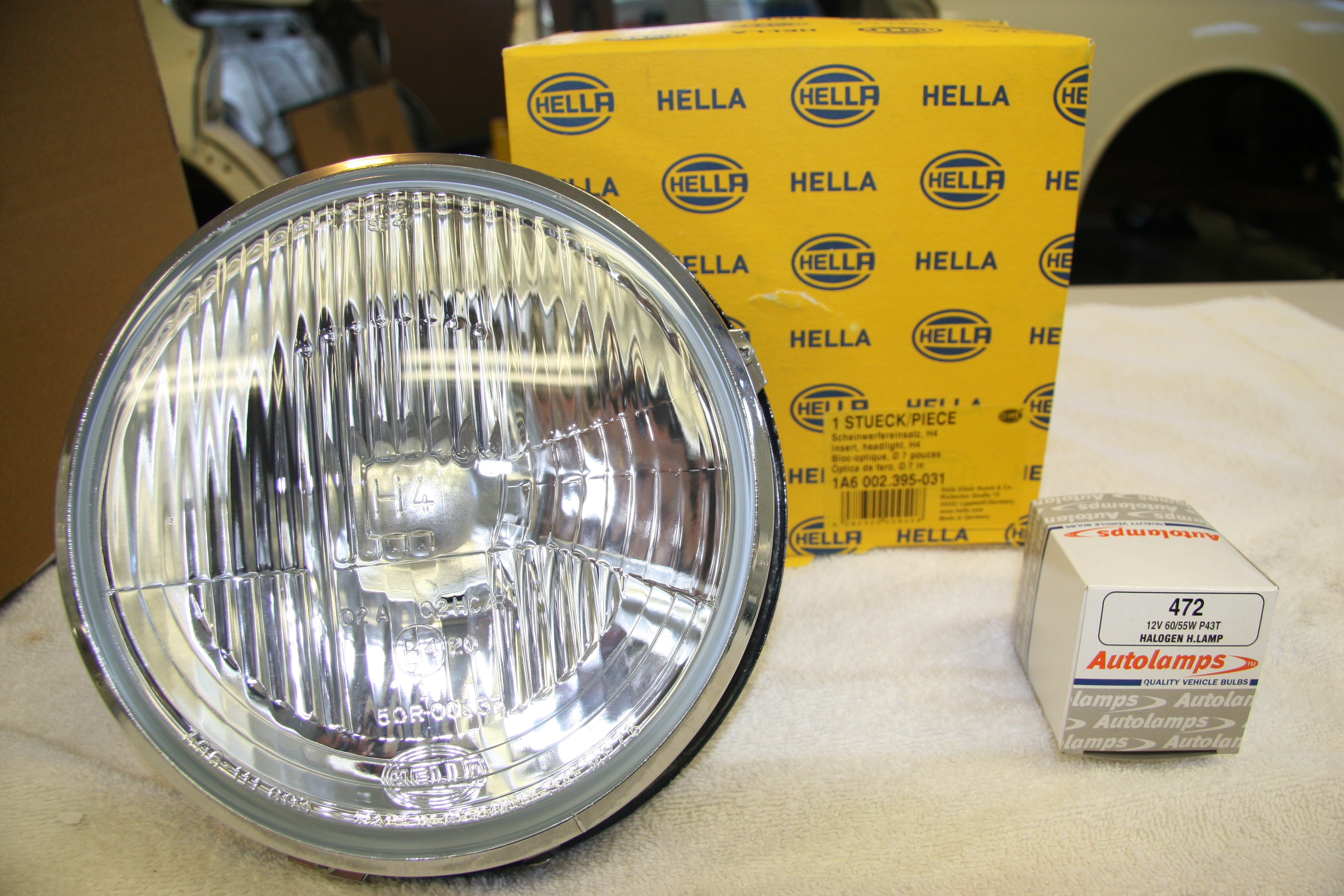
I decided to upgrade the lighting from the original sealed beams and ordered the halogen kit available from SNG Barratt. The Hella lamp number is 1A6 002.395-031 and the bulb is Autolamps Halogen, 472 12V 60/55W P43T. Generating a 5amp requirement per bulb.
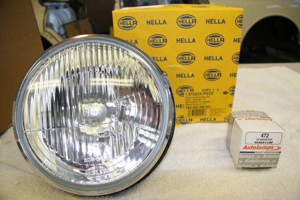
Hella Halogen Headlamps

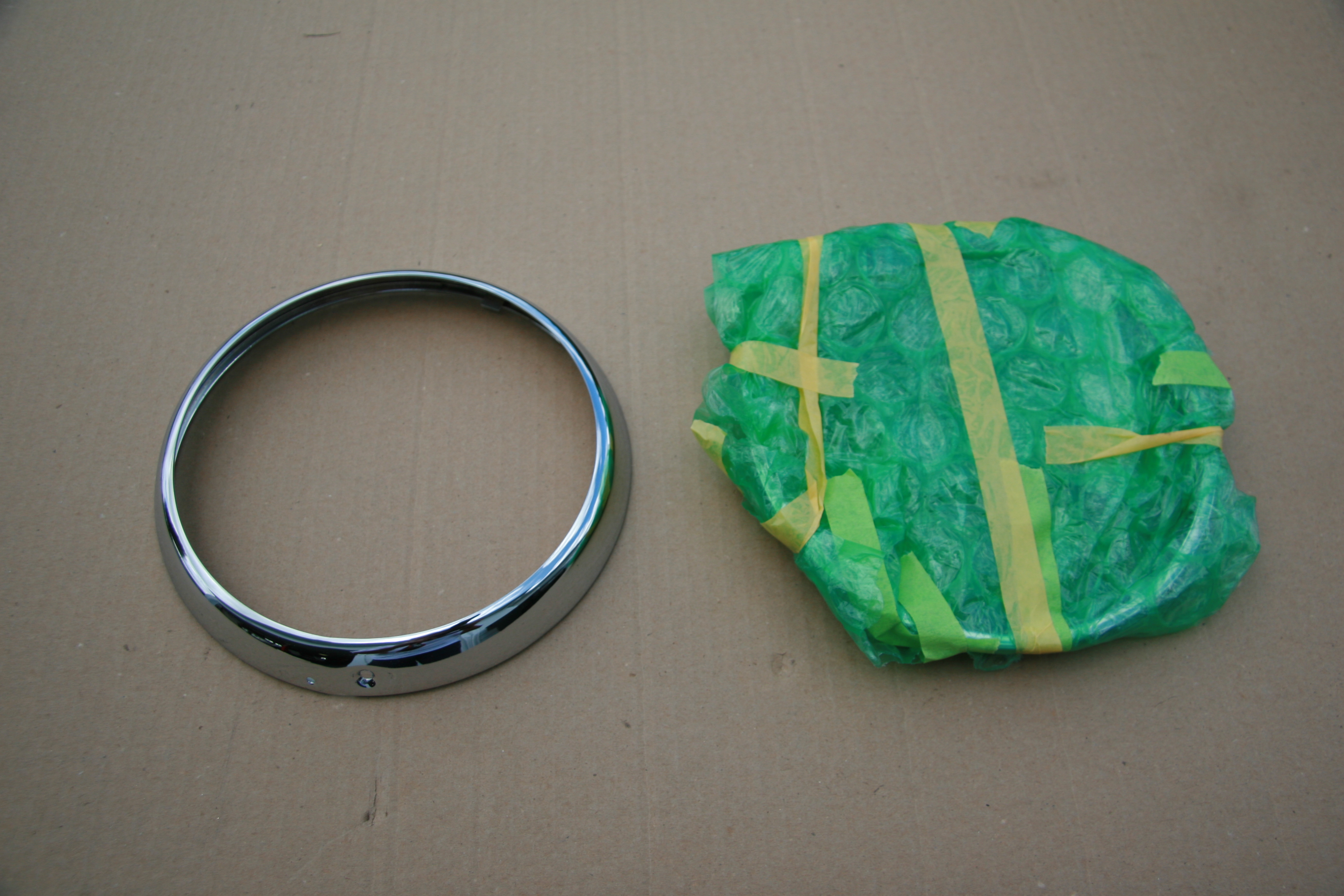
Headlamp Outer Rim
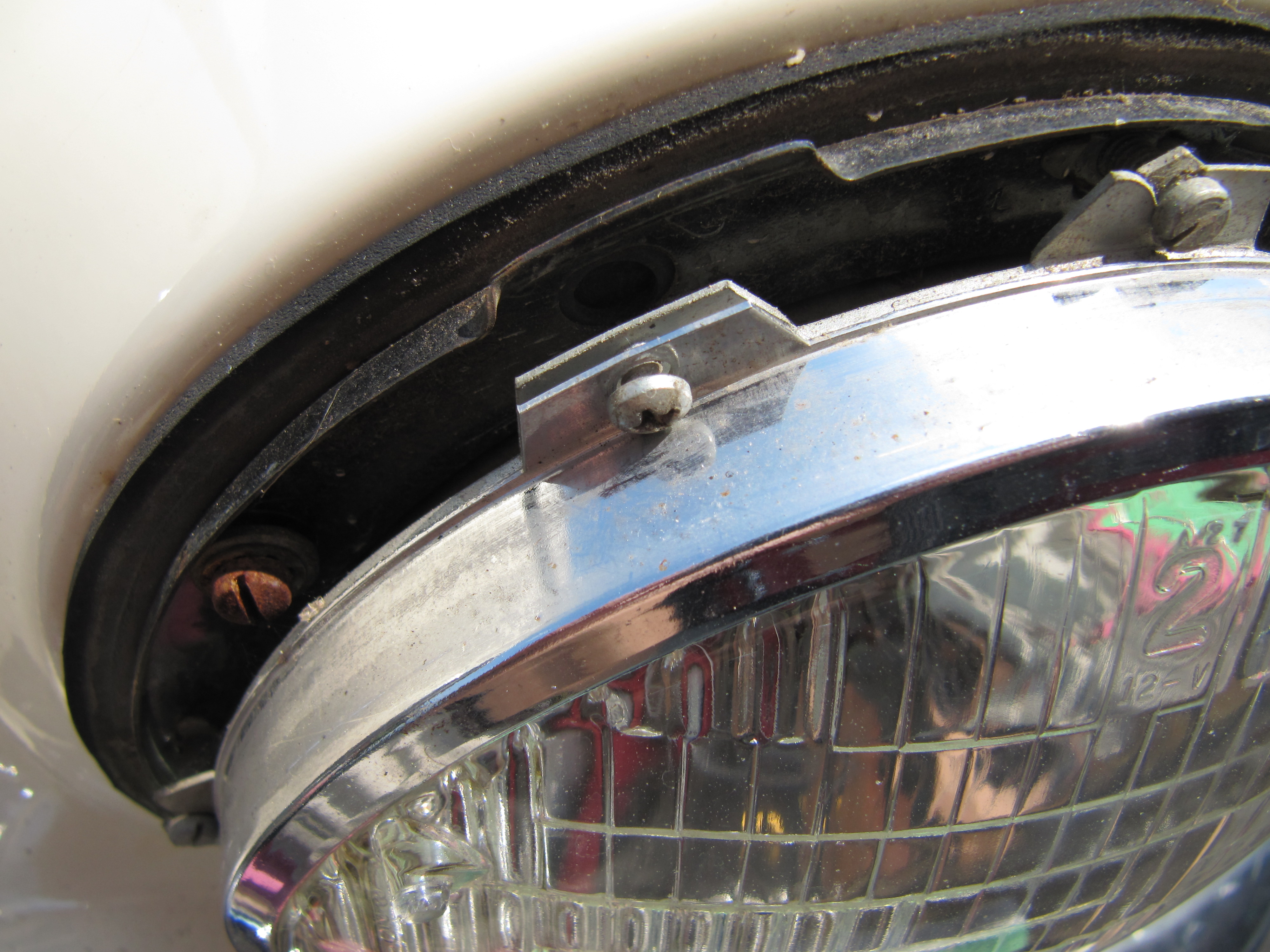
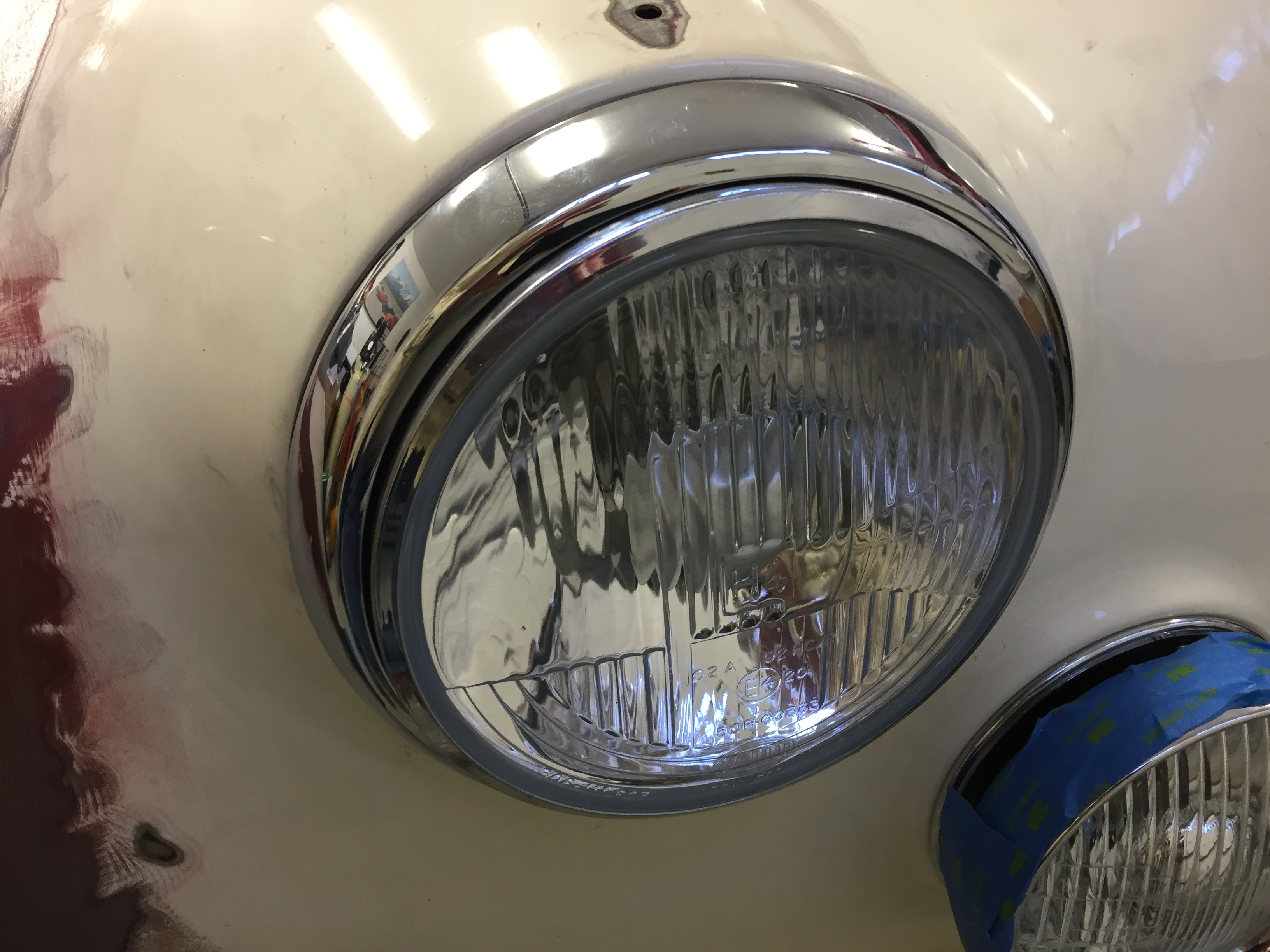
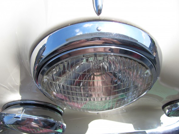
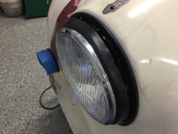
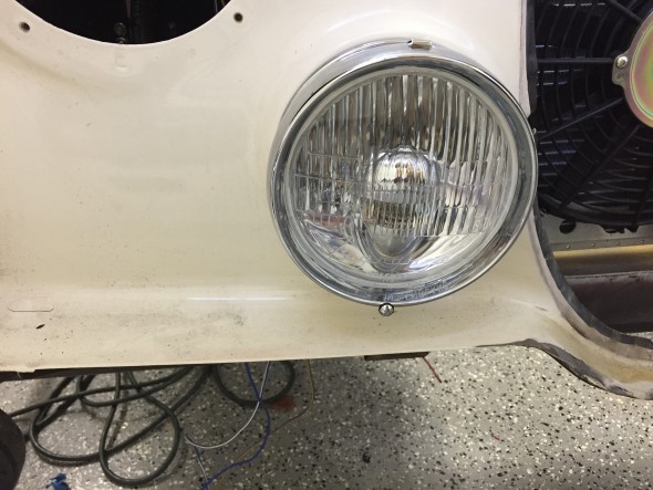
I had the original headlamp rims rechromed and they look great! These images show the headlights installed temporarily for electric circuit testing. They are not adjusted for focal point.
Headlight Dust Excluder in Place

Headlight Installed with Newly Chromed Trim Ring
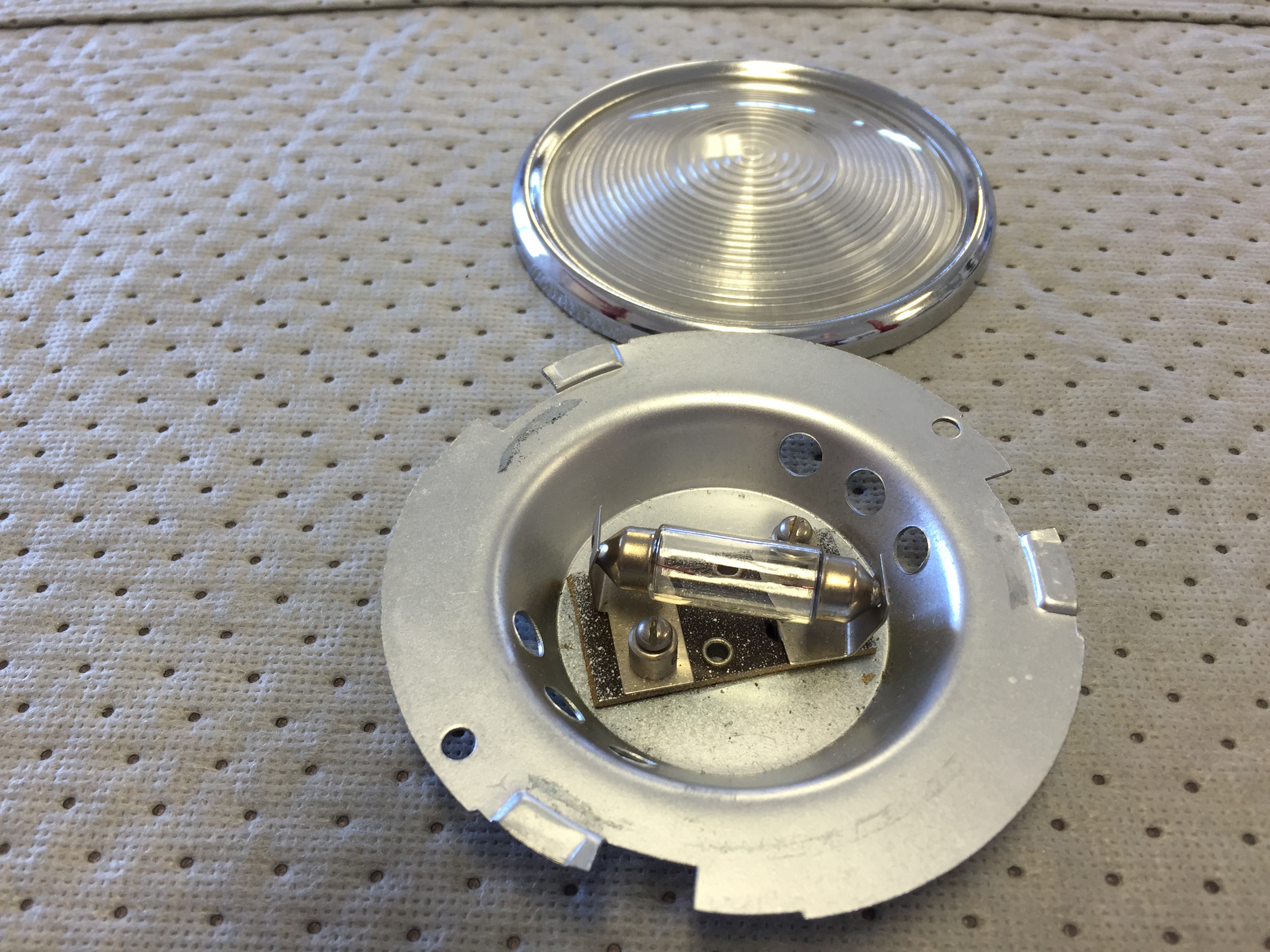
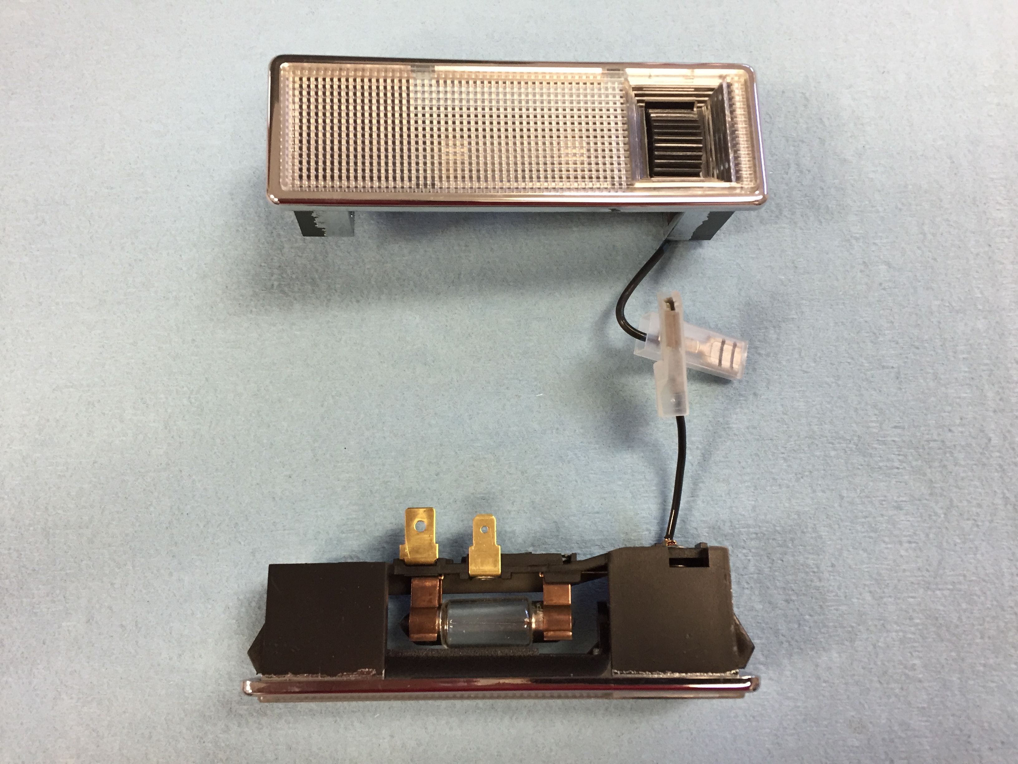
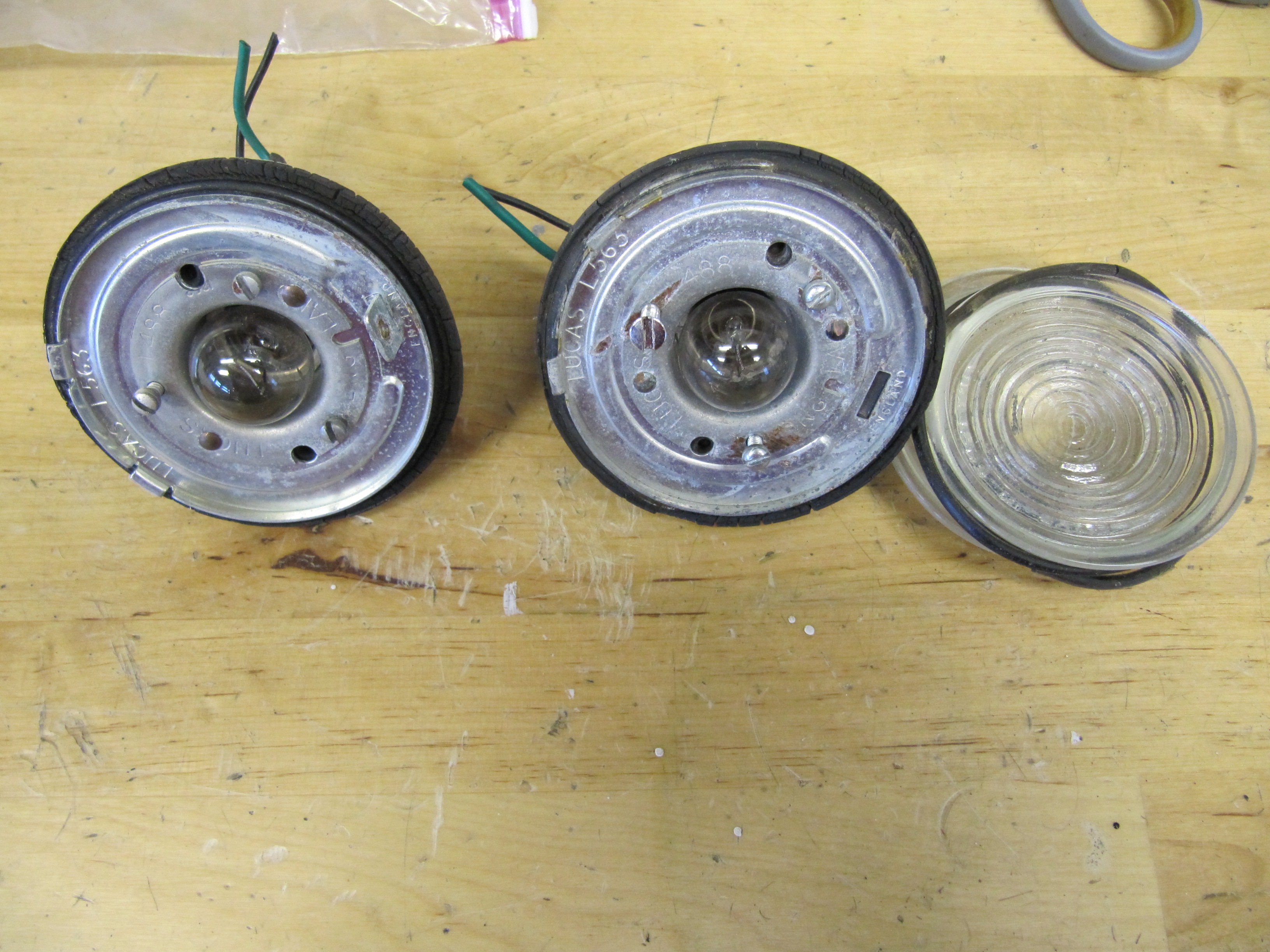
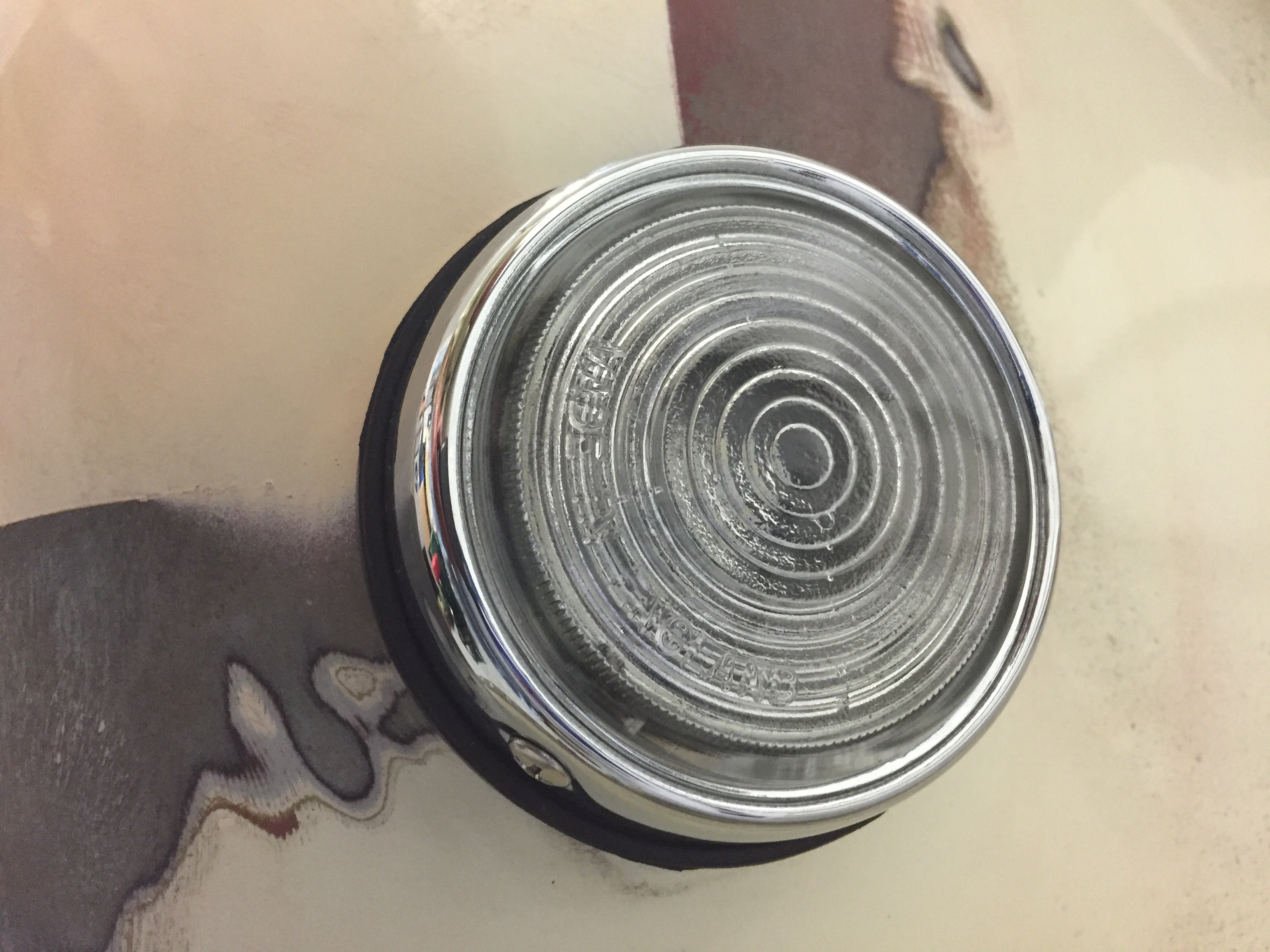
Front Flasher Lamp
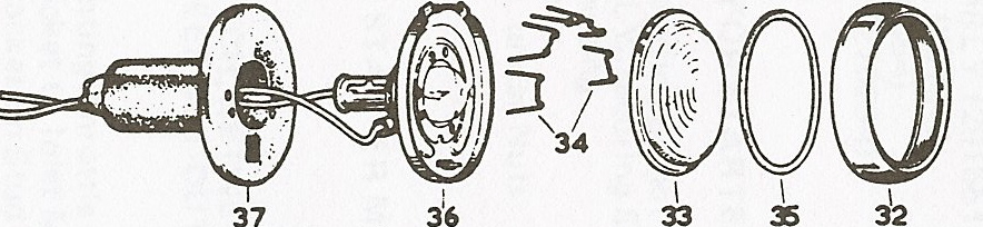
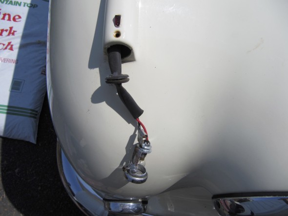
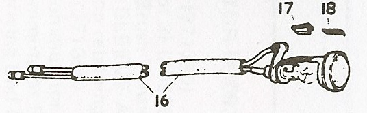
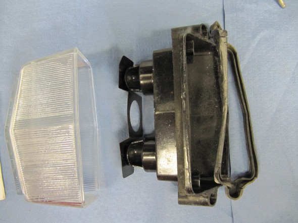
The front flasher lamps consist of a chrome rim, a clear lens, lens retaining wires, a lens seating gasket, a bulb holder and seating plate, the terminal sleeve, a 21 watt bulb (C.9126), and a rubber body.
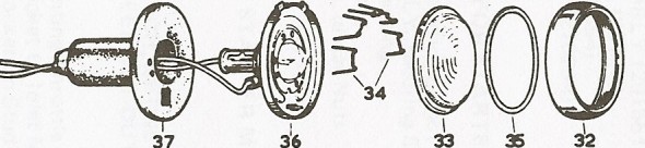
Front Flasher Lamp
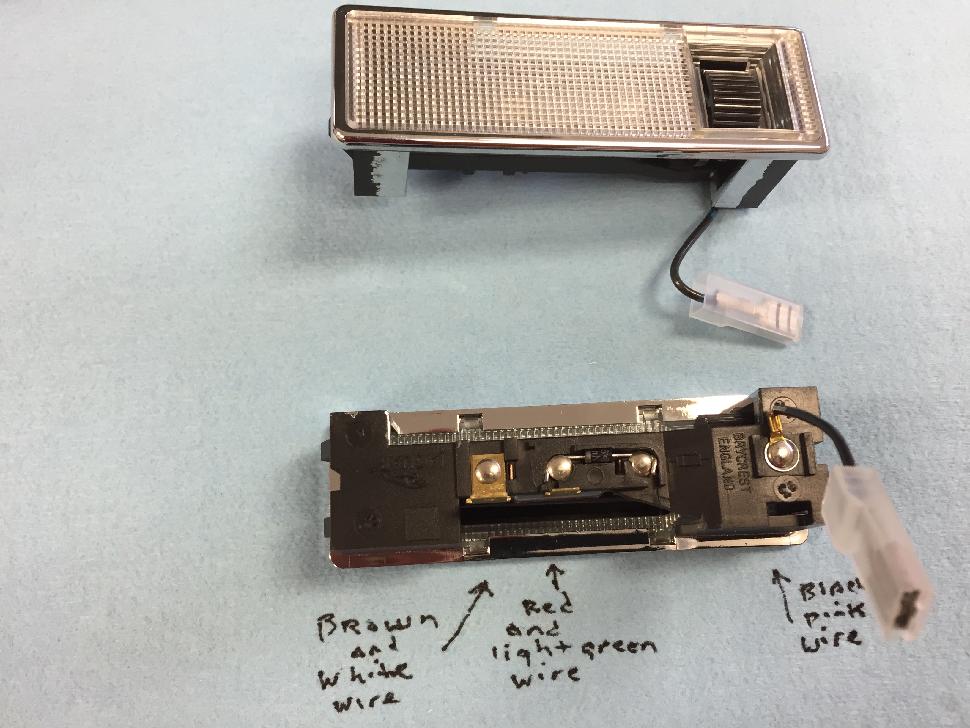
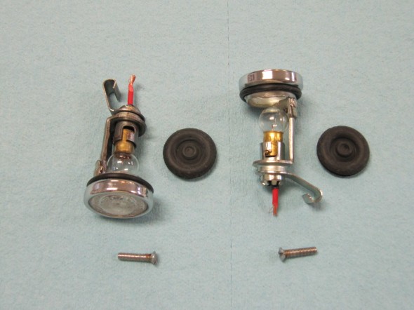
My original seating plates were in good shape; however, I replaced the lens, retaining wires, lens seating gasket, chrome rim, and rubber body with new items.
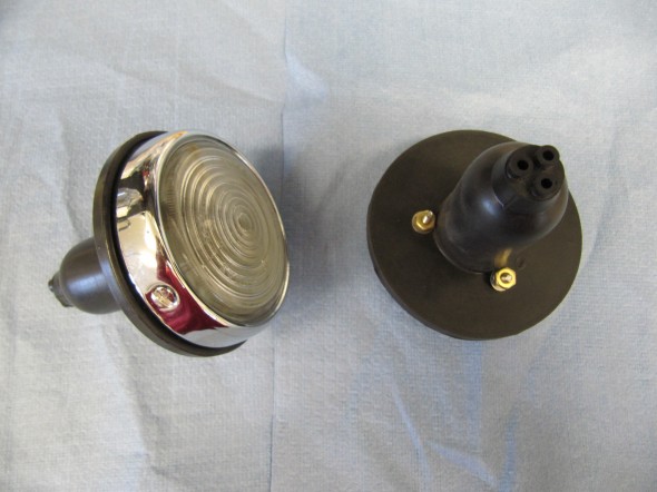
New Assembled Front Flashers

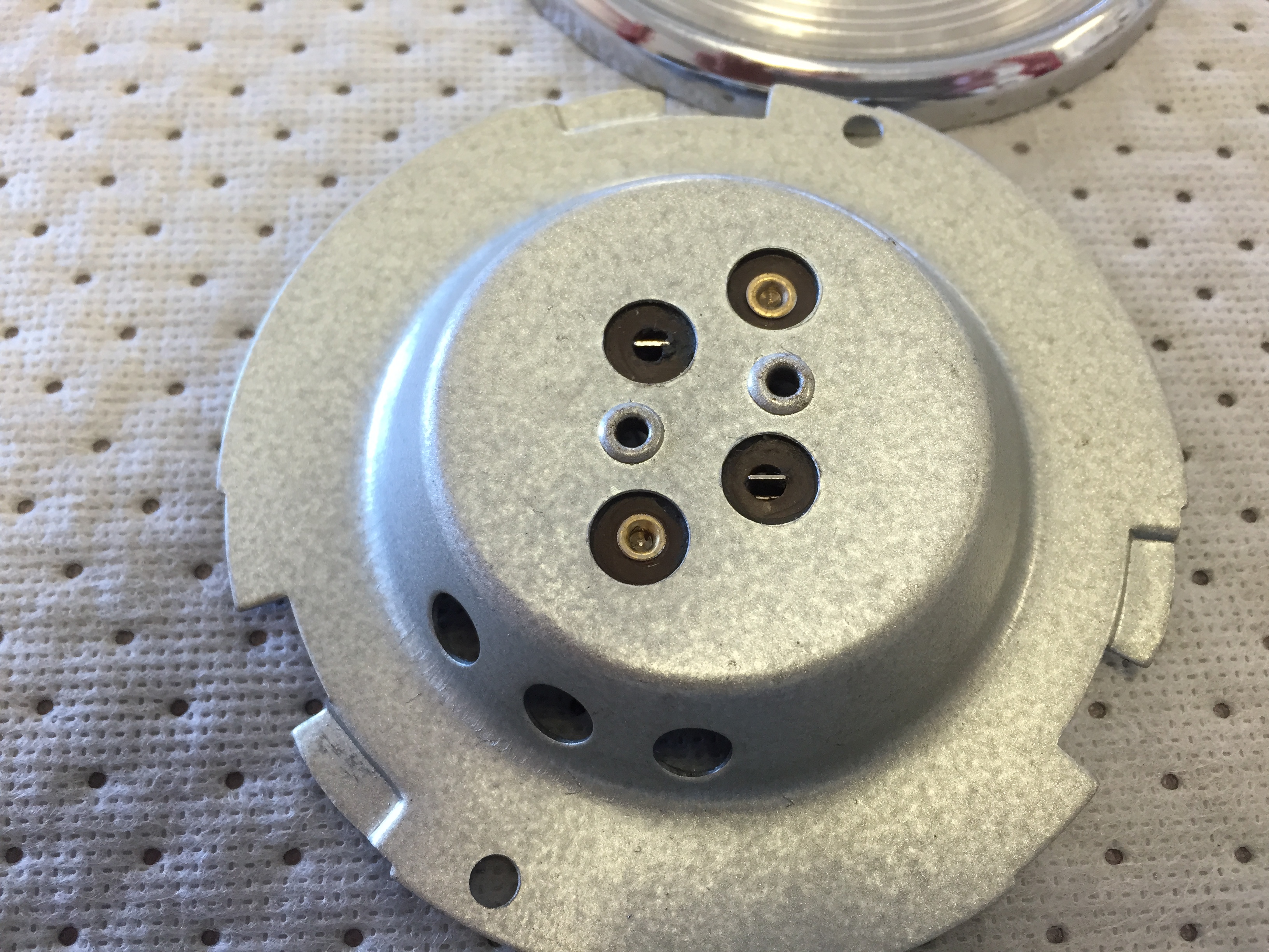
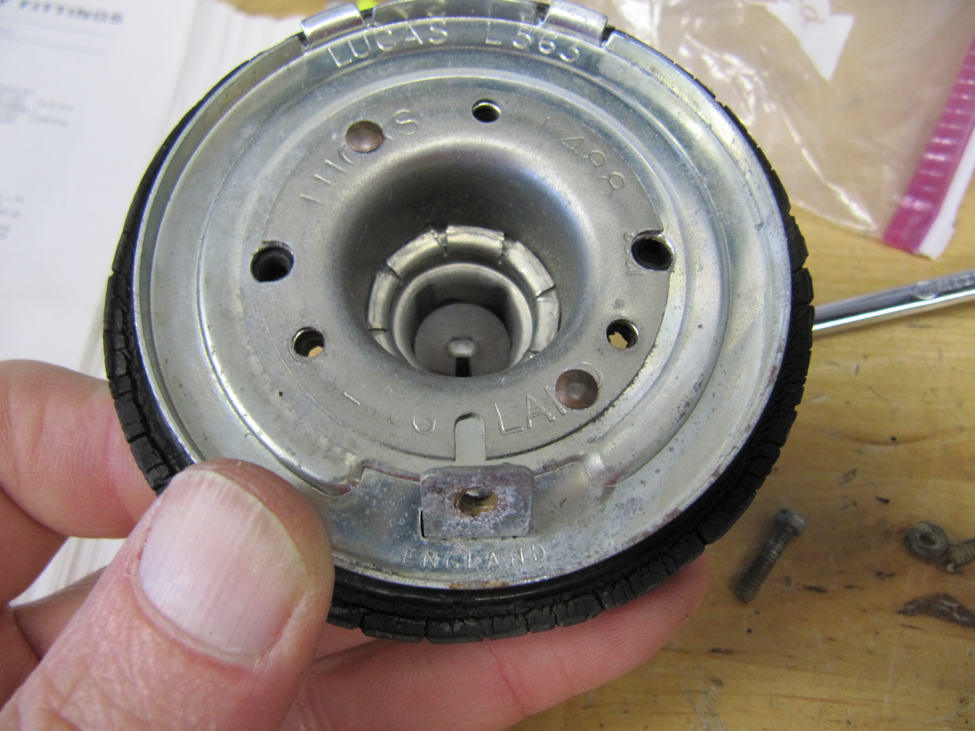
Seating Plate

Seating Plates

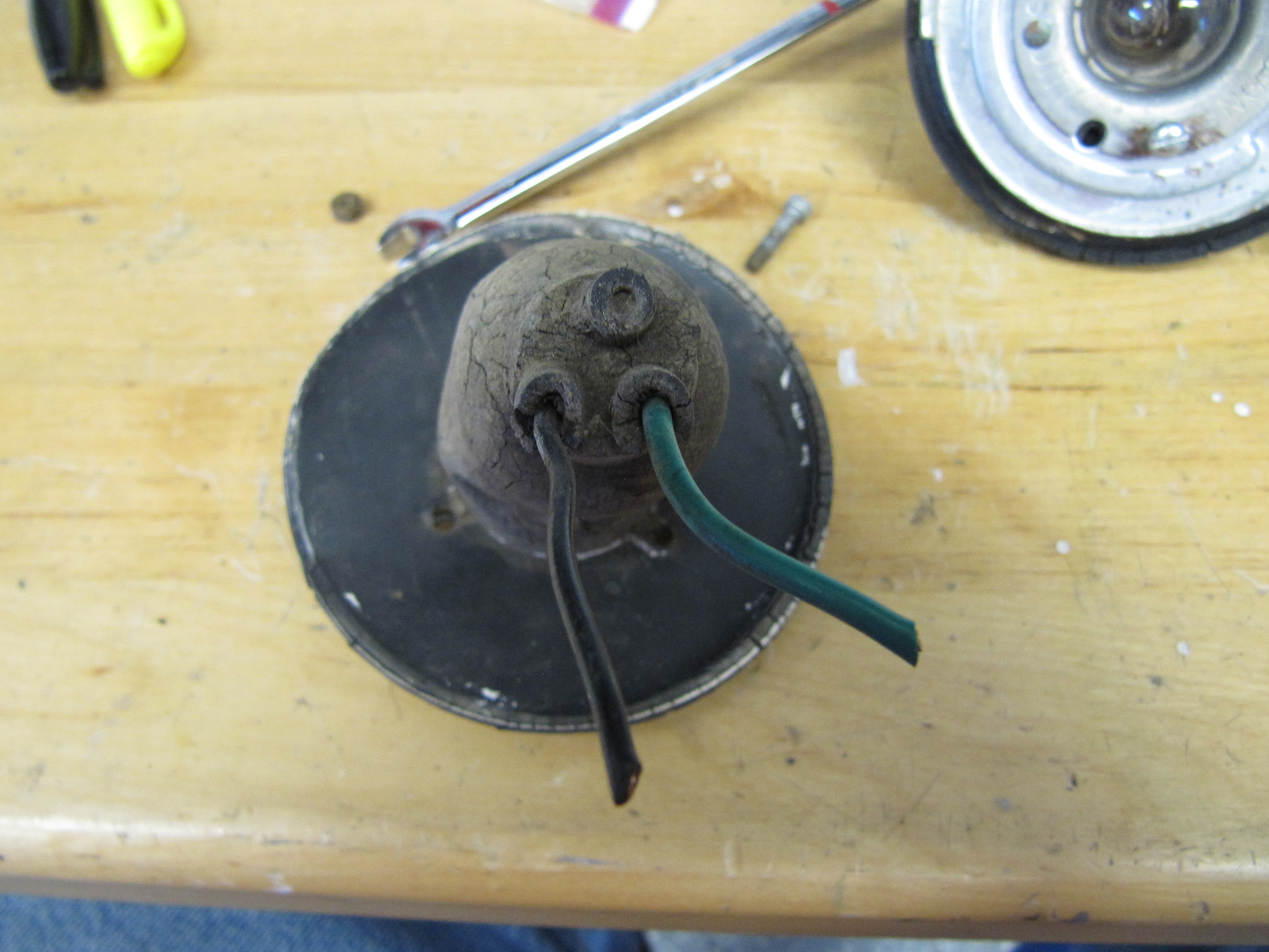
Rubber Boot
I also disassembled the wiring terminal in the fixture and installed new wiring in the lamp. When assembled to the car, the three machine screws securing the rubber boot to the car body should not be over-tightened as this makes snapping on the chrome lens surround almost impossible! New LED flasher bulbs “382Flashers” were sourced from 4Sight Automotive and installed as substitutes for the original incandescent bulbs.
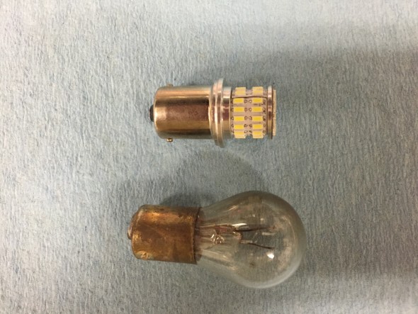
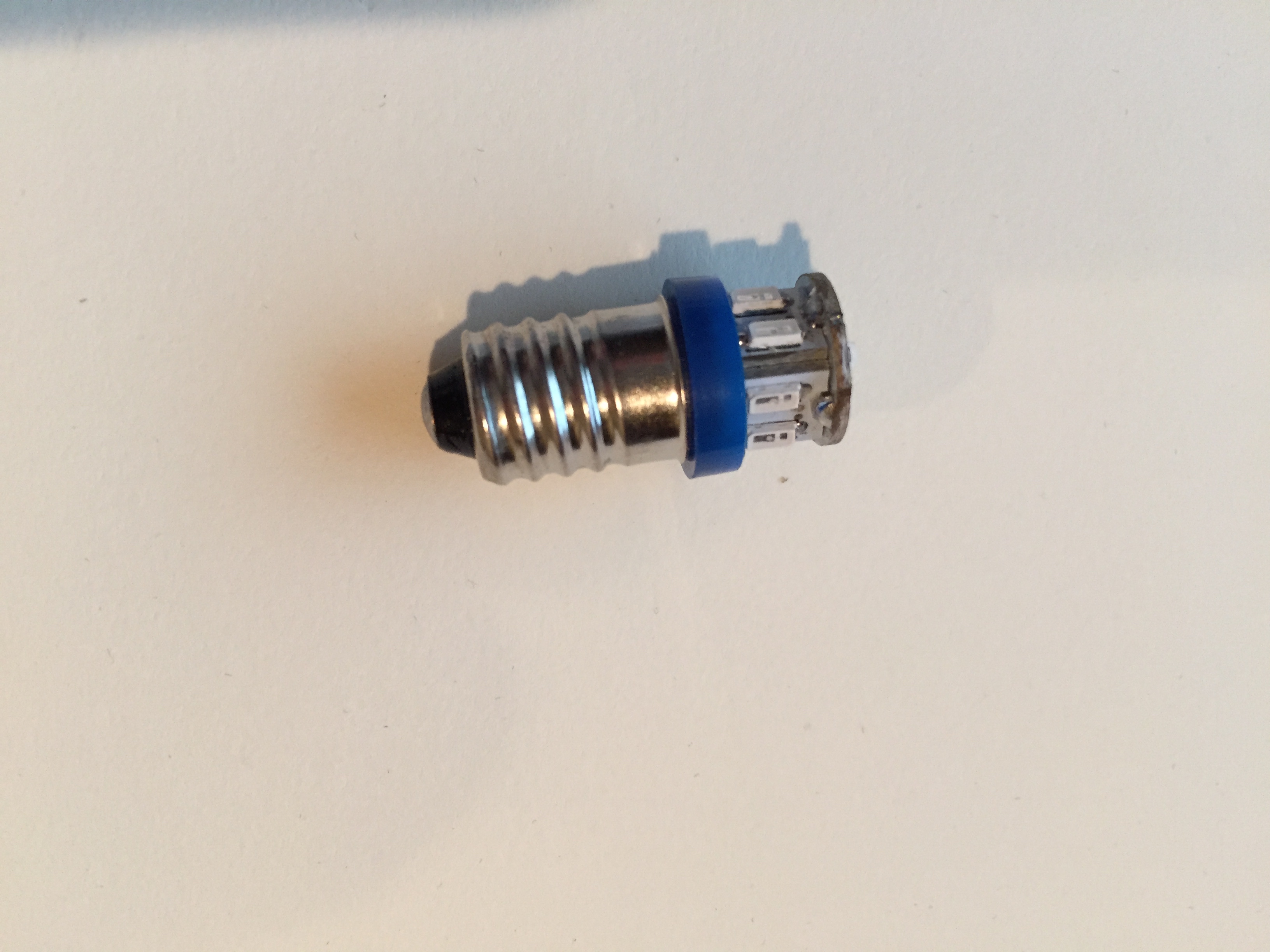
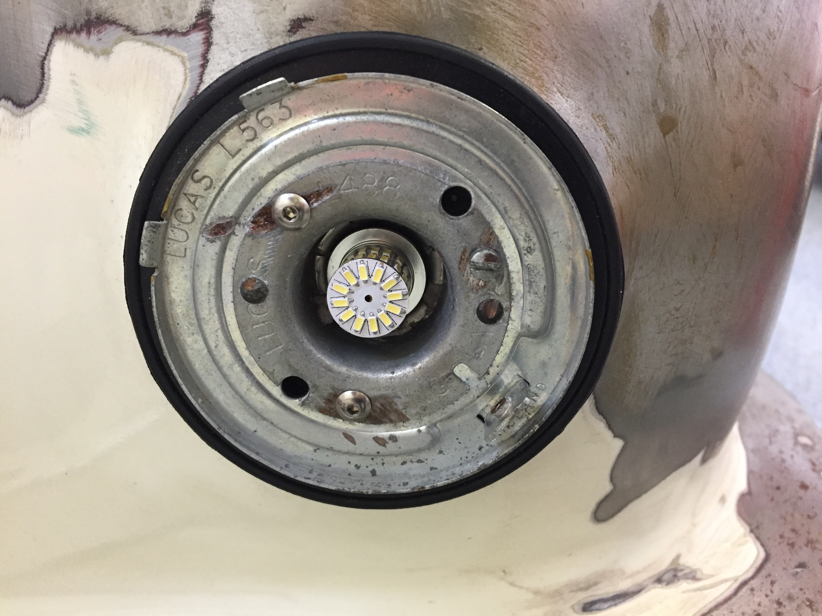
Original 21 Watt Bulb with New LED

Turn Signal Flasher with LED Installed
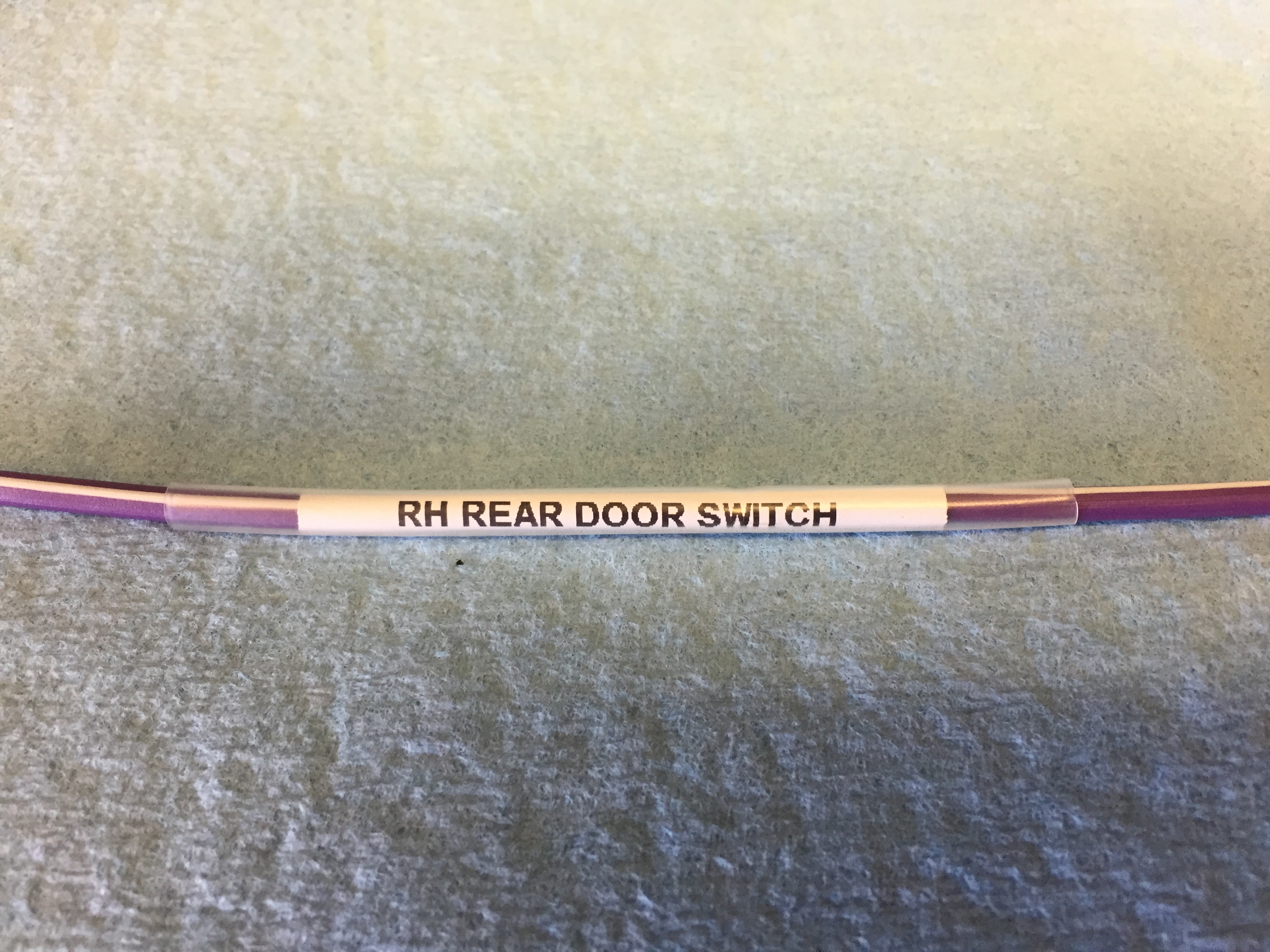
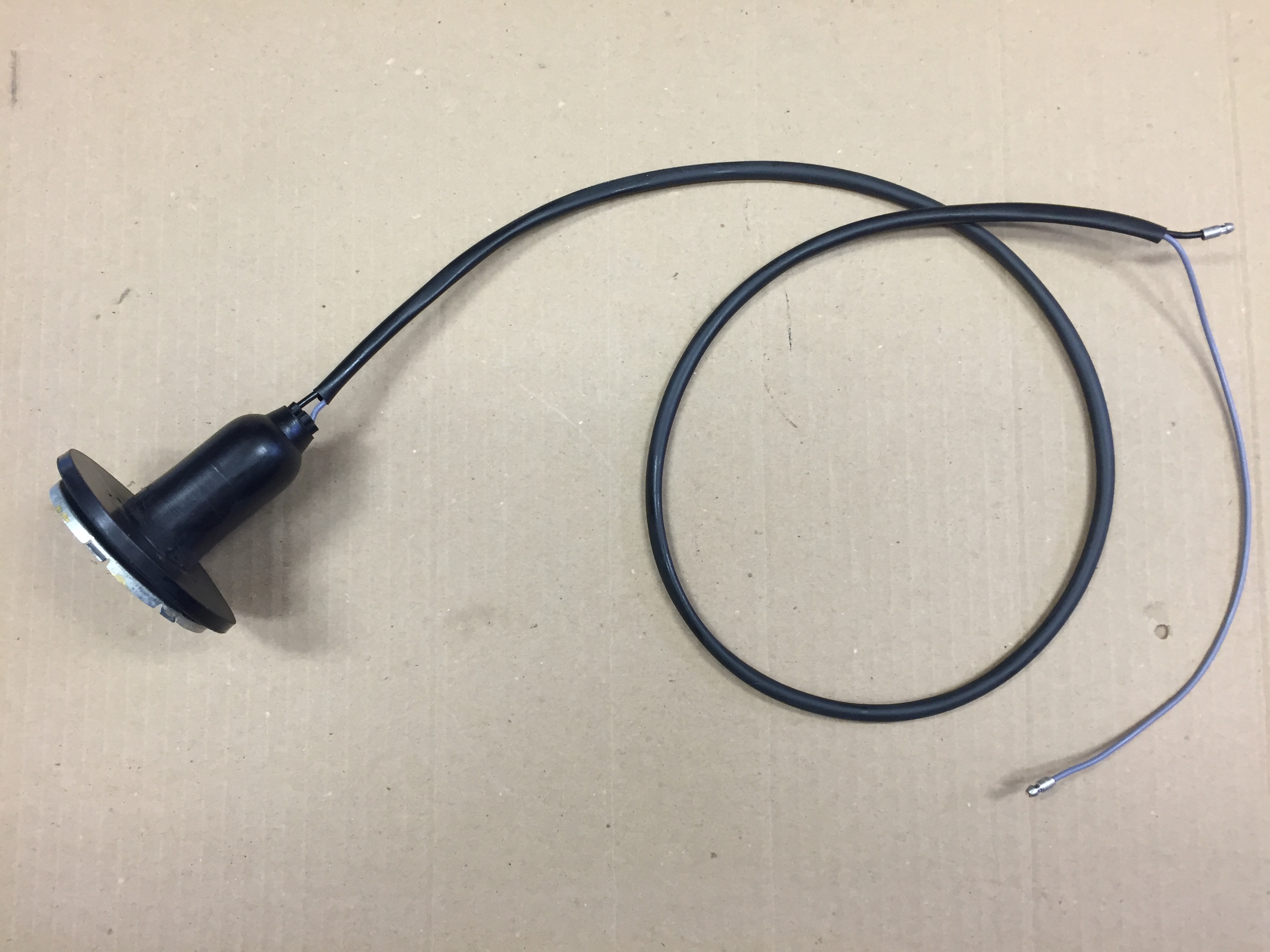
I added all new sleeving for the wiring of all of the lamps in the car.
More information about the wiring for the flasher lamps may be found at the Building a New Wiring Harness post.

Front Flasher Turn signal
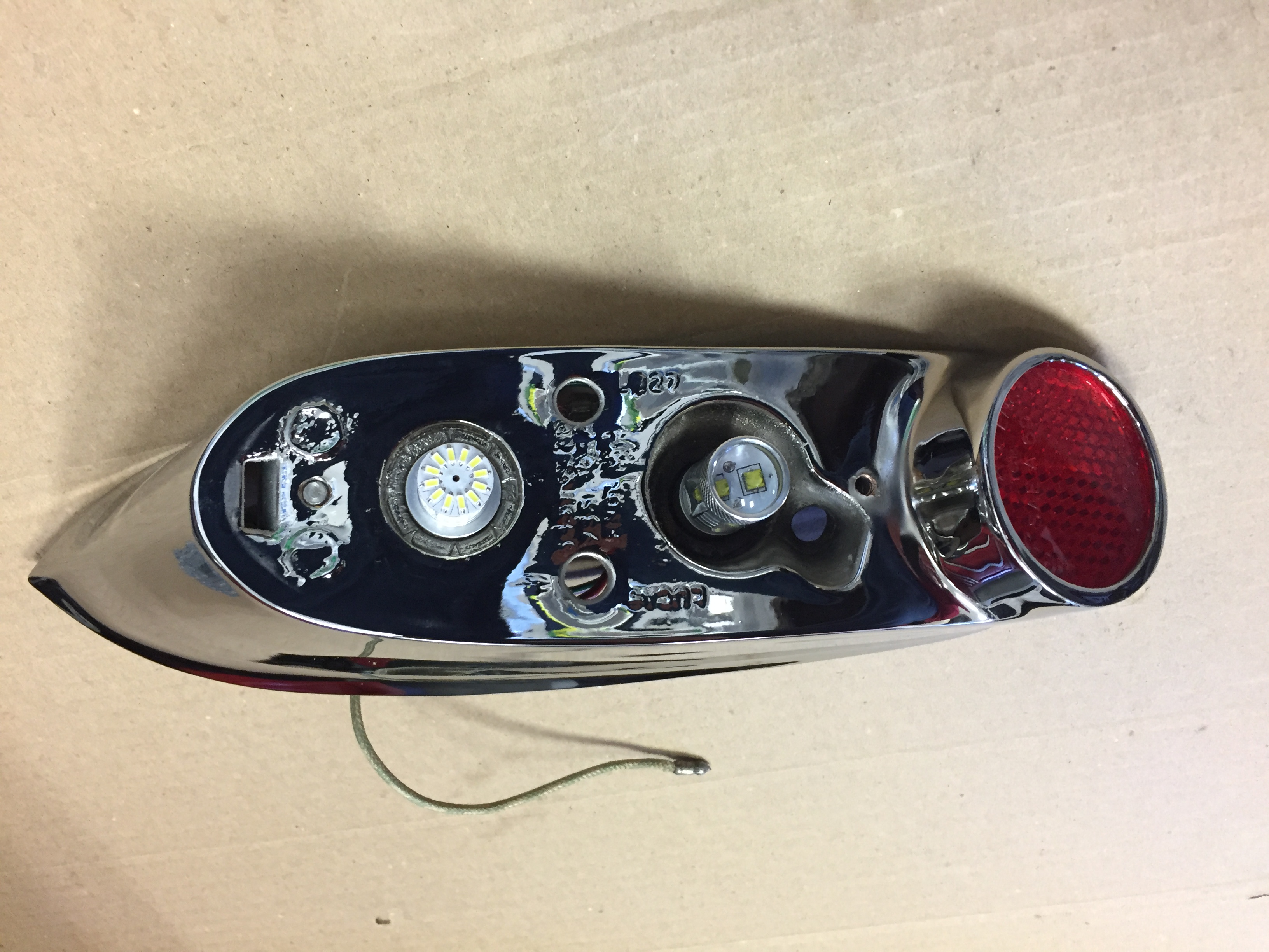
Tail Lights
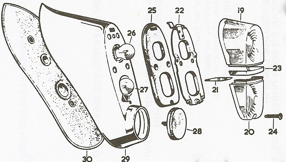
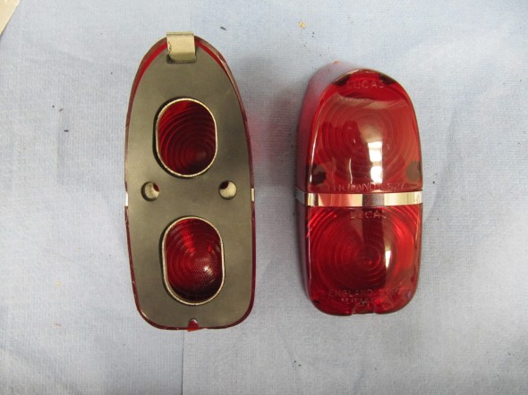
MK2 Tail Light
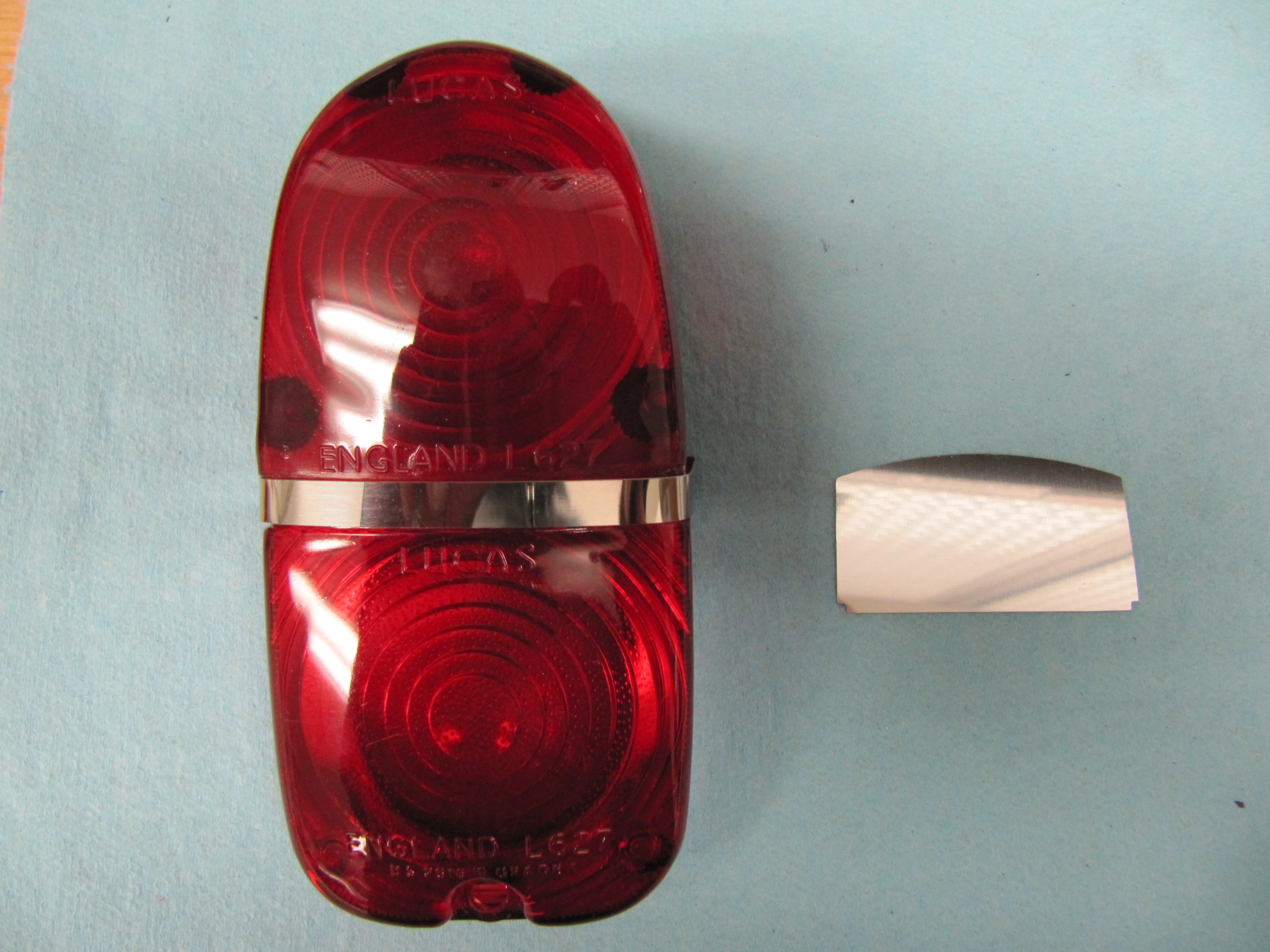
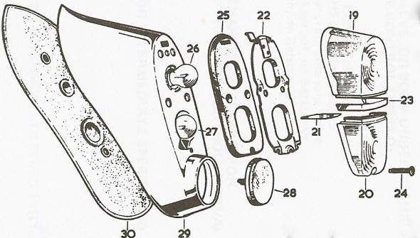
The tail light is comprised of two lens halves. These halves are held together by a chrome clip, between the flasher and the stop/tail lens. A chrome shield also separates the two halves to prevent light bleed from one lens to the other. A metal mounting plate also holds the halves together and serves as the base for the assembly to the chrome plinth. The mounting plate is secured to the plastic lens with six 3/8″ self-tapping screws. A rubber gasket then seals the unit to the plinth. The lens assembly is secured to the plinth with a top clip on the metal mounting plate and with a chrome machine screw at the bottom.
I was able to use the original metal mounting plates and screws, but purchased new lenses, the chrome clips, the shields, and rubber gaskets.
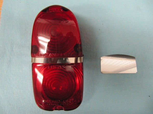
Taillight with Shield
Tail Light Assembled
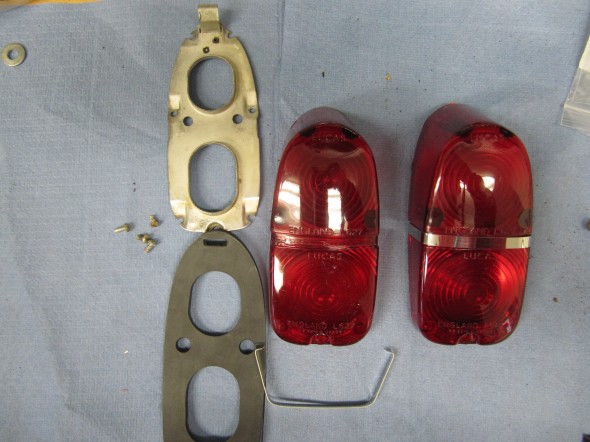
Tail Light Parts
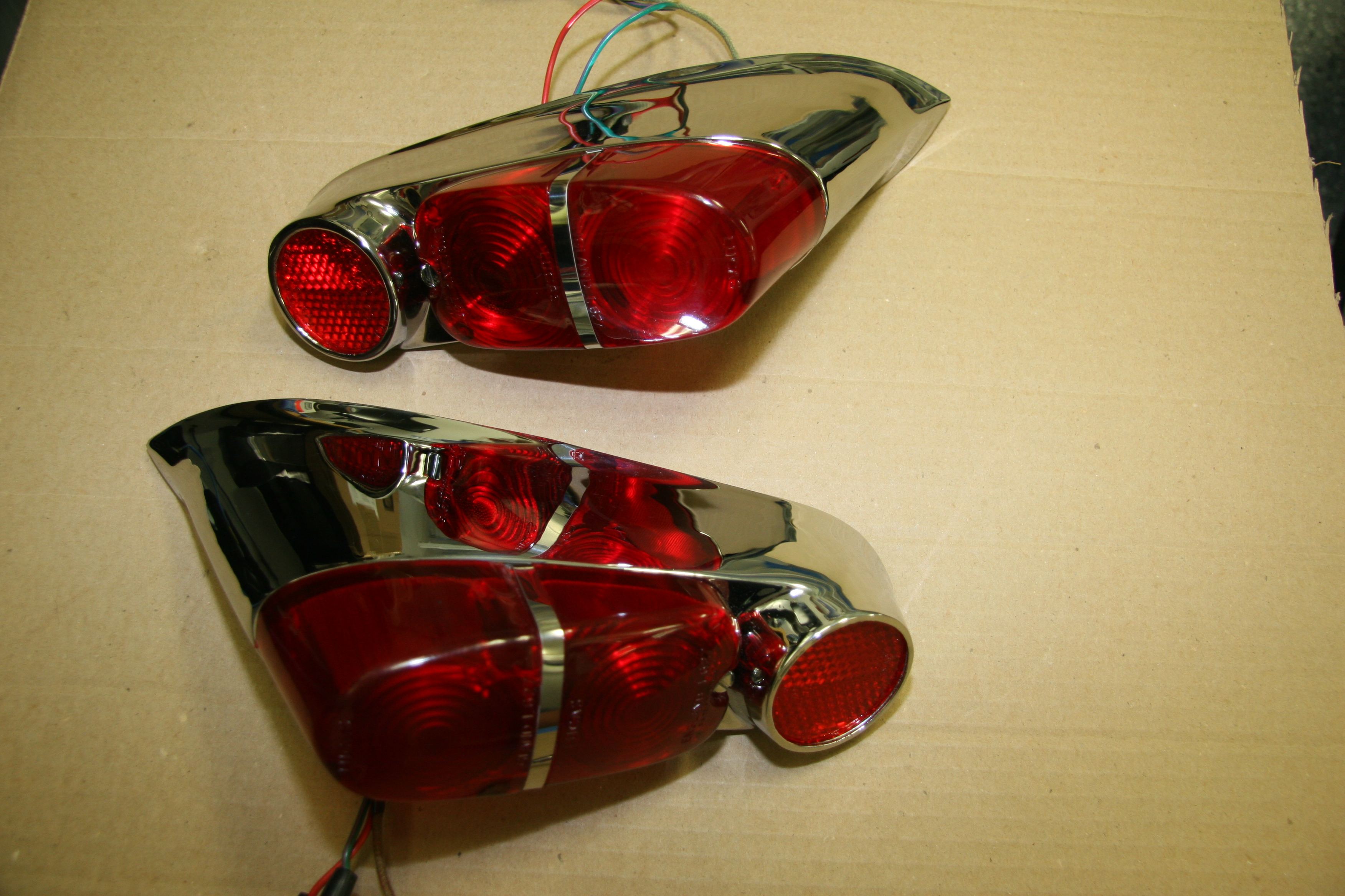
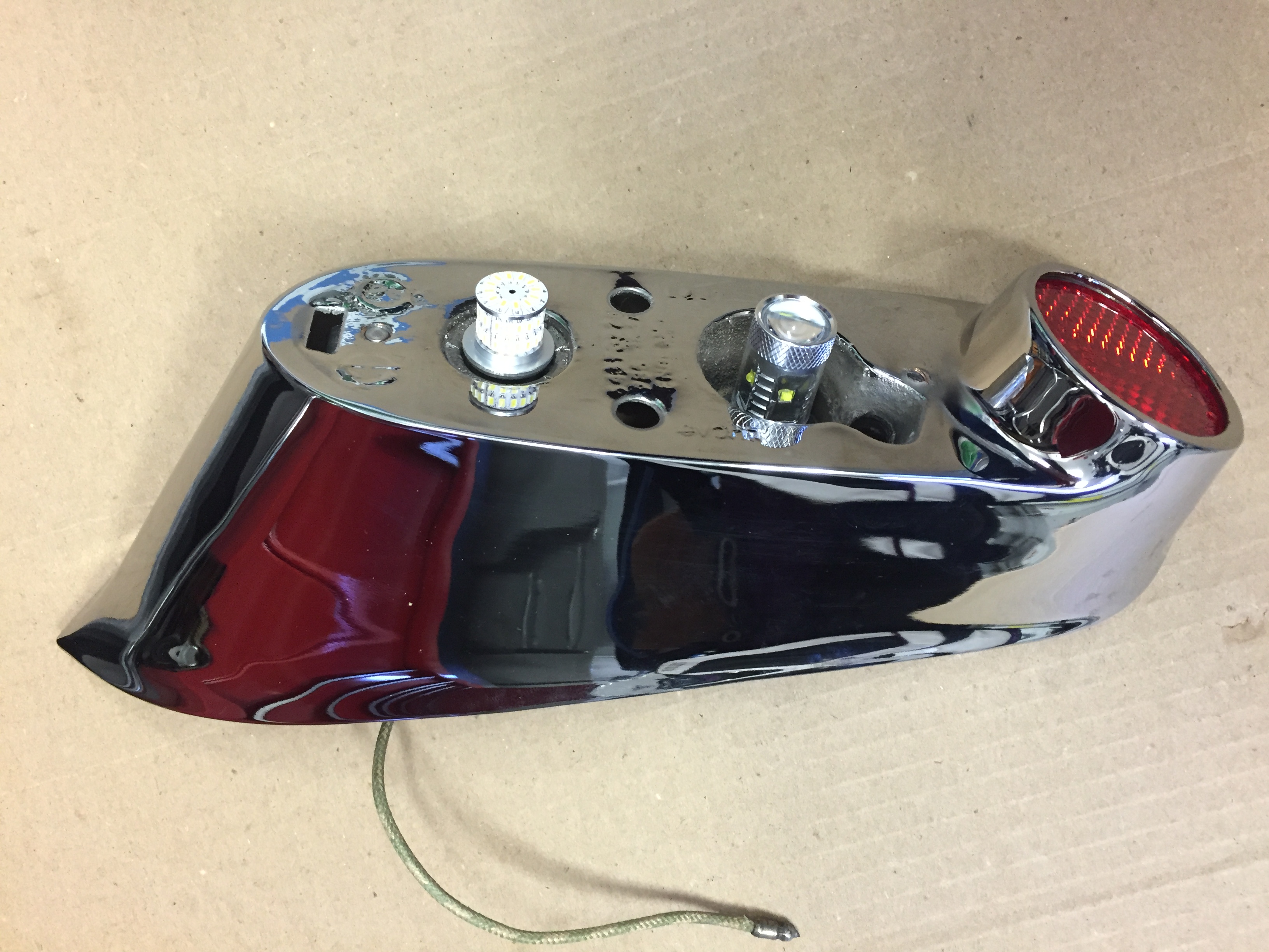
I had the two rear tail light plinths rechromed as they were pitted badly. I still need to install the reflectors and then the lights will look quite good. Each light assembly fastens to the body with two screws. The lower is a Whitworth fillister screw 1 1/4″ long and it fastens to a captive nut in the body. The upper mount is a stud in the assembly that goes through a mounting hole in the body and then has a washer and nut on the interior side. The original upper bulb is an 1156 and the lower bulb is an 1157. However, as with the other exterior lights, these bulbs were replaced with LED flasher bulbs “382Flashers” and “380HP LED stop & tail light bulbs” sourced from 4Sight Automotive . I was able to use the original wiring leads.
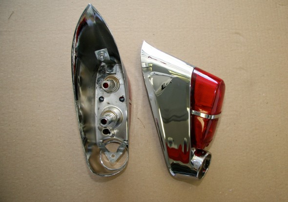
Tail Light Assemblies New Chrome Missing Reflectors

Tail Lights Assembled with Lucas Reflectors
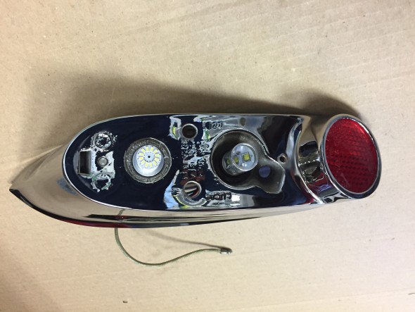
Tail Light LED Bulbs

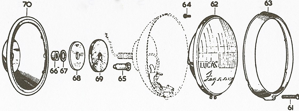
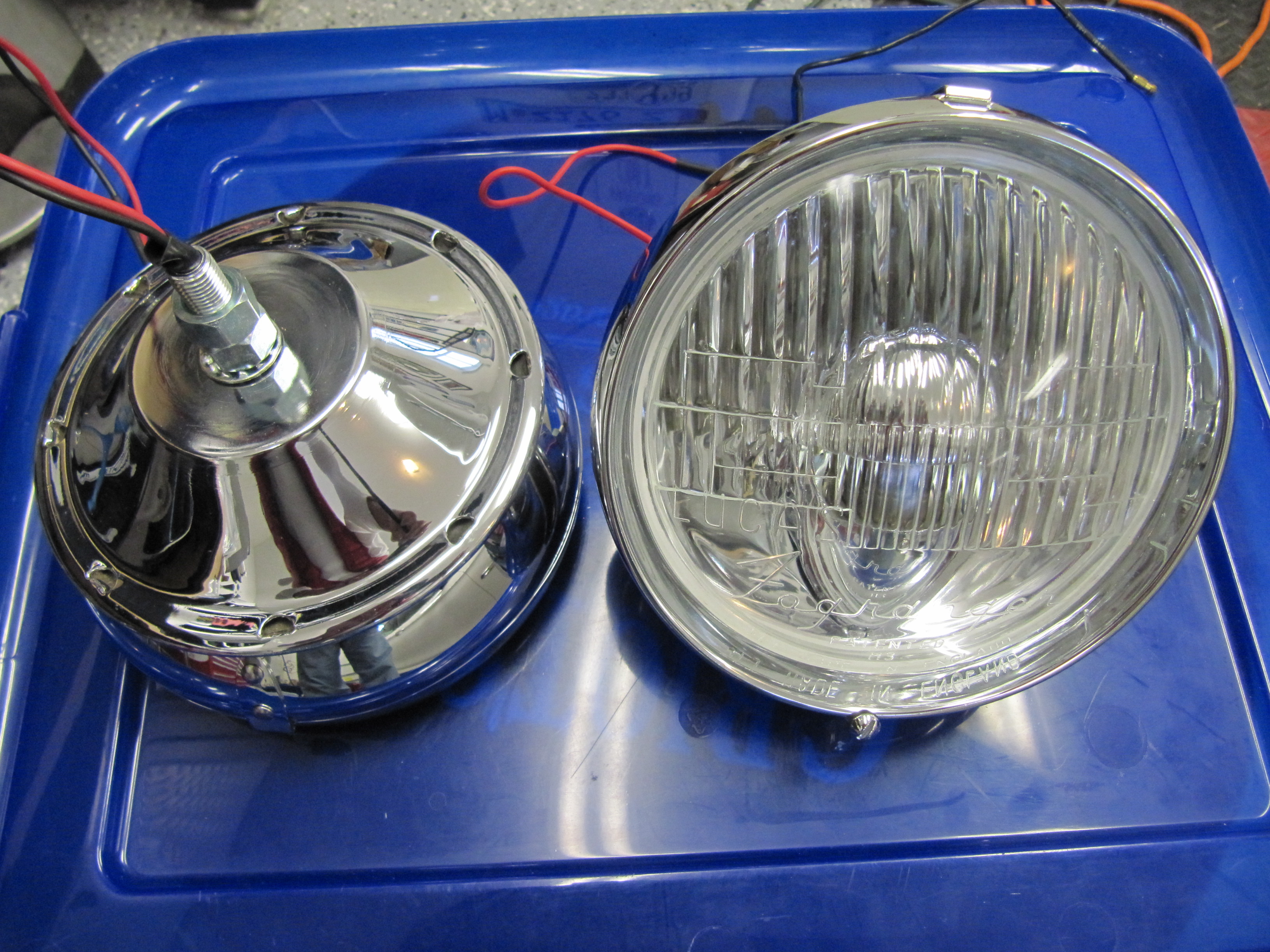
Lucas FogRanger Fog Lamps
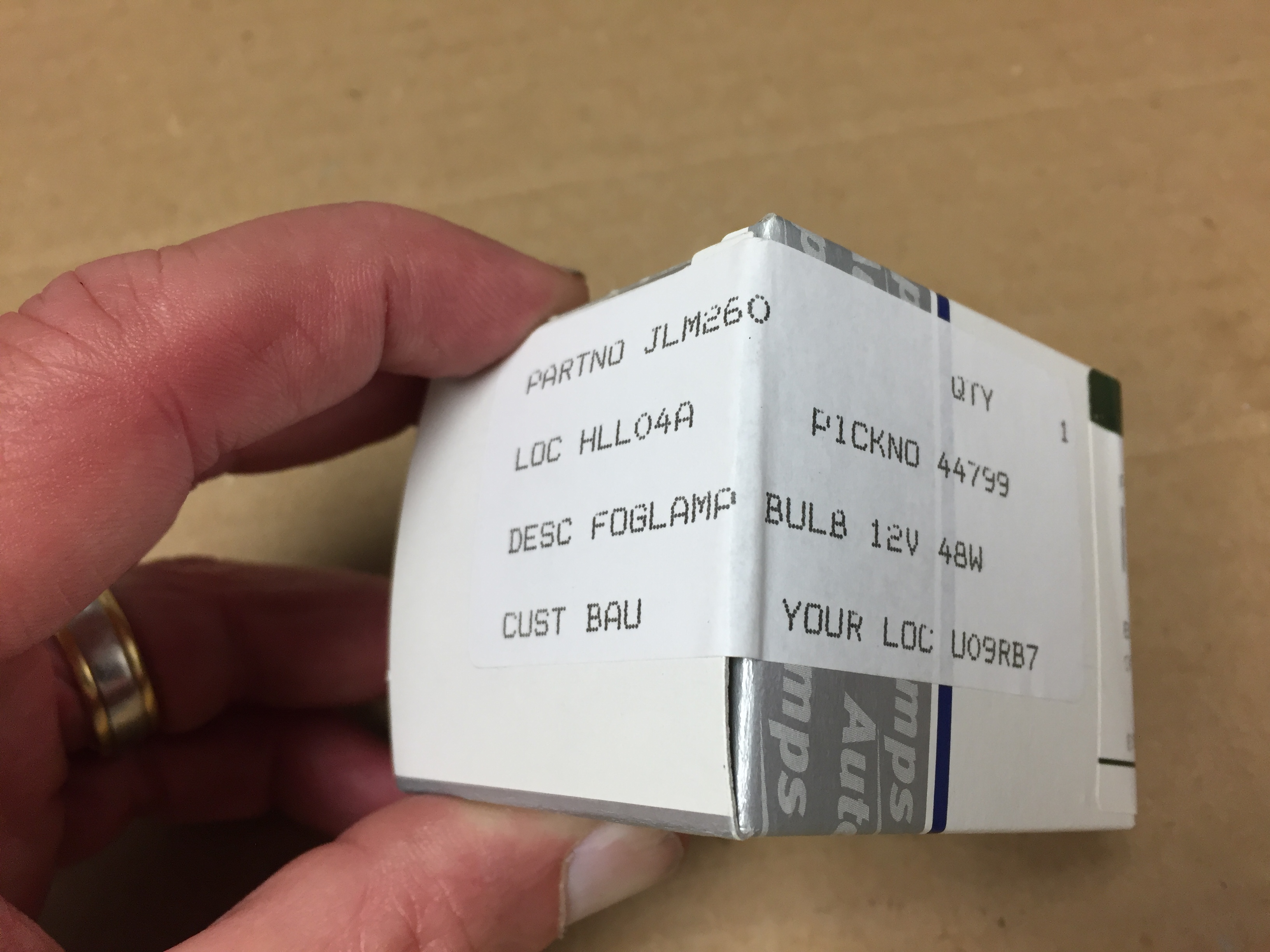
The original FogRanger lamps were functional and certainly reusable, but they are such a visible component of the front-end appearance of the MK2, that I decided to purchase new lamps. The embellishers were in good shape, so I was able to clean, polish and assemble with the new lamps. All new wiring was used and while I did not use LED bulbs for the Fograngers, I did install new Autolamps 12 volt, 48 Watt bulbs in both lamps, sourced from SNG Barratt.

Fogranger Bulb 12V 48W SNG Barratt

Fogranger Fog Lamp

FogRanger Lamp Assemblies

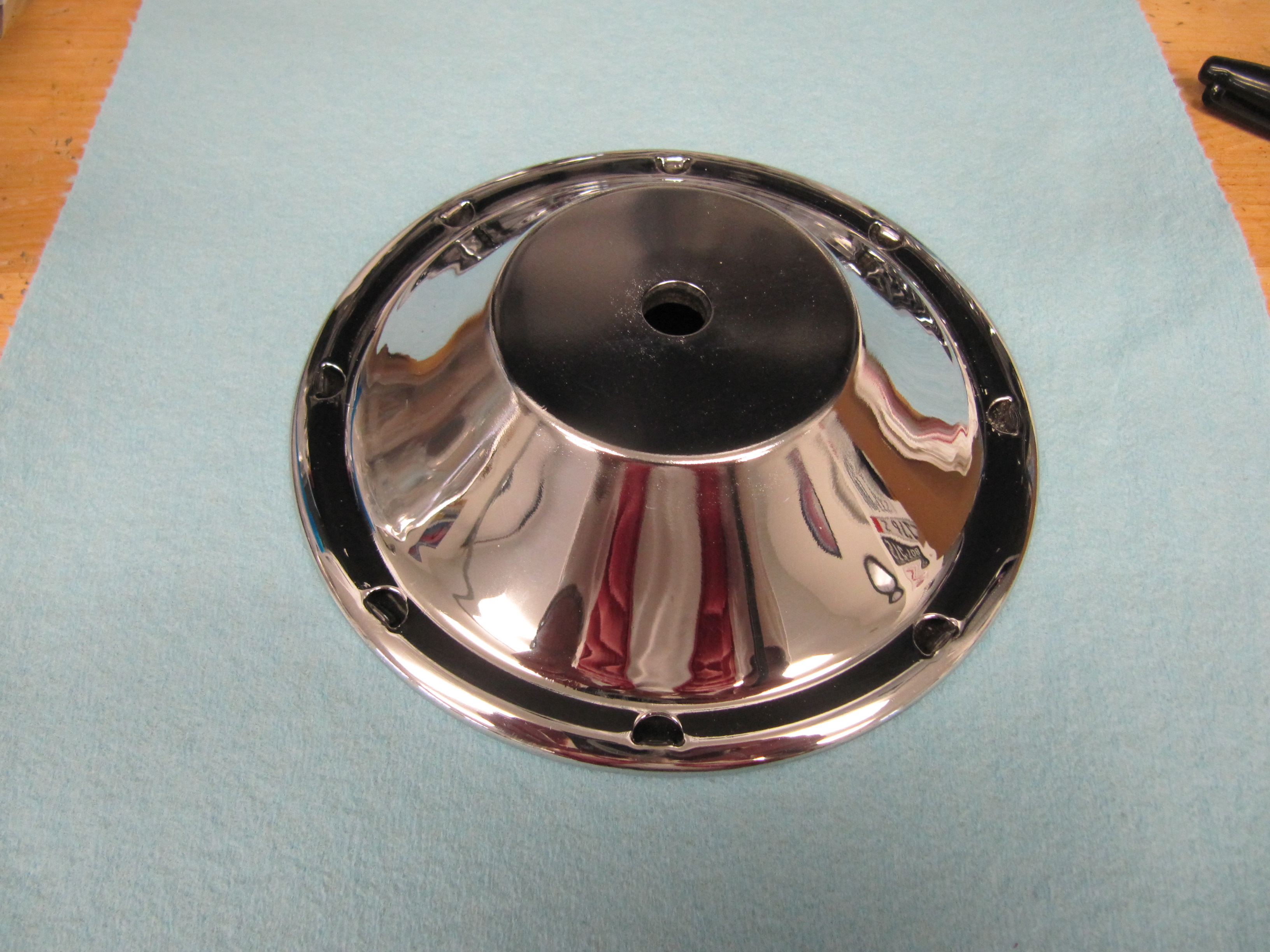
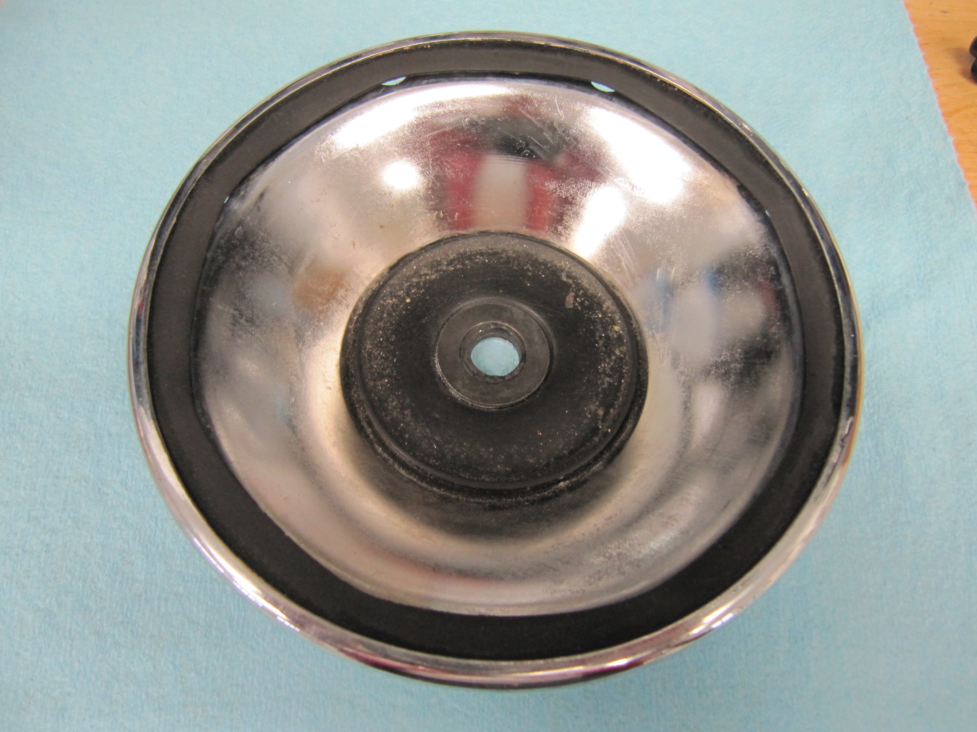
Fog Lamp Embellisher

Fog Lamp Embellisher
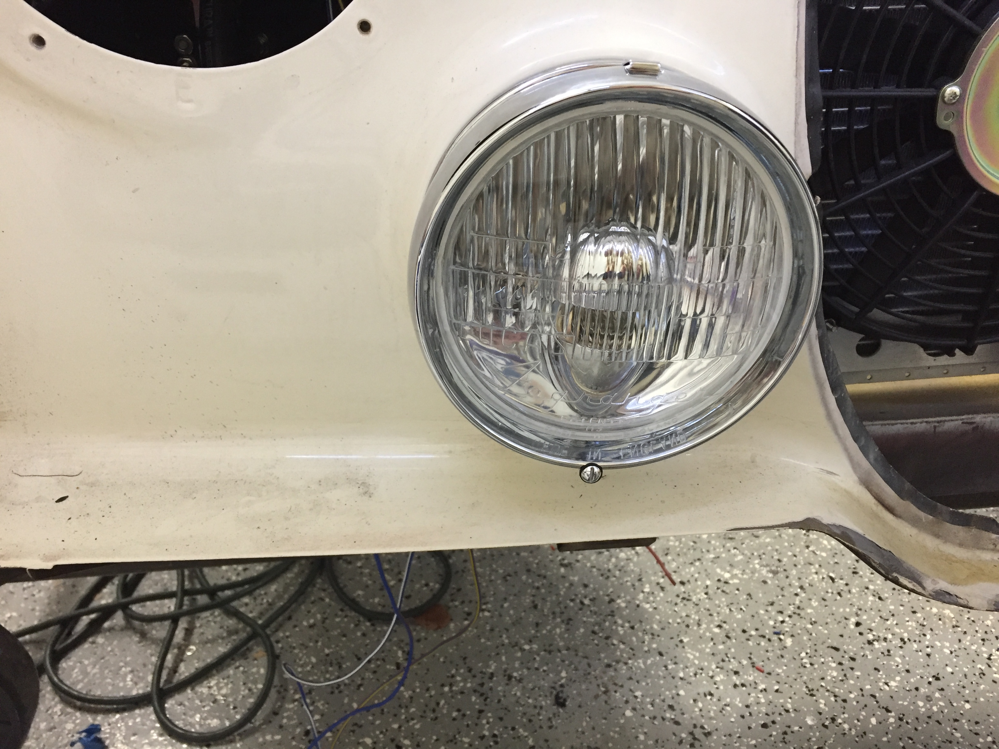
This is an image of the RH Fogranger lamp temporarily installed on the car. As with the headlights, the fograngers are not adjusted for proper angles at this point. This installations was merely to test electric circuits and switches.
RH Fogranger Installed
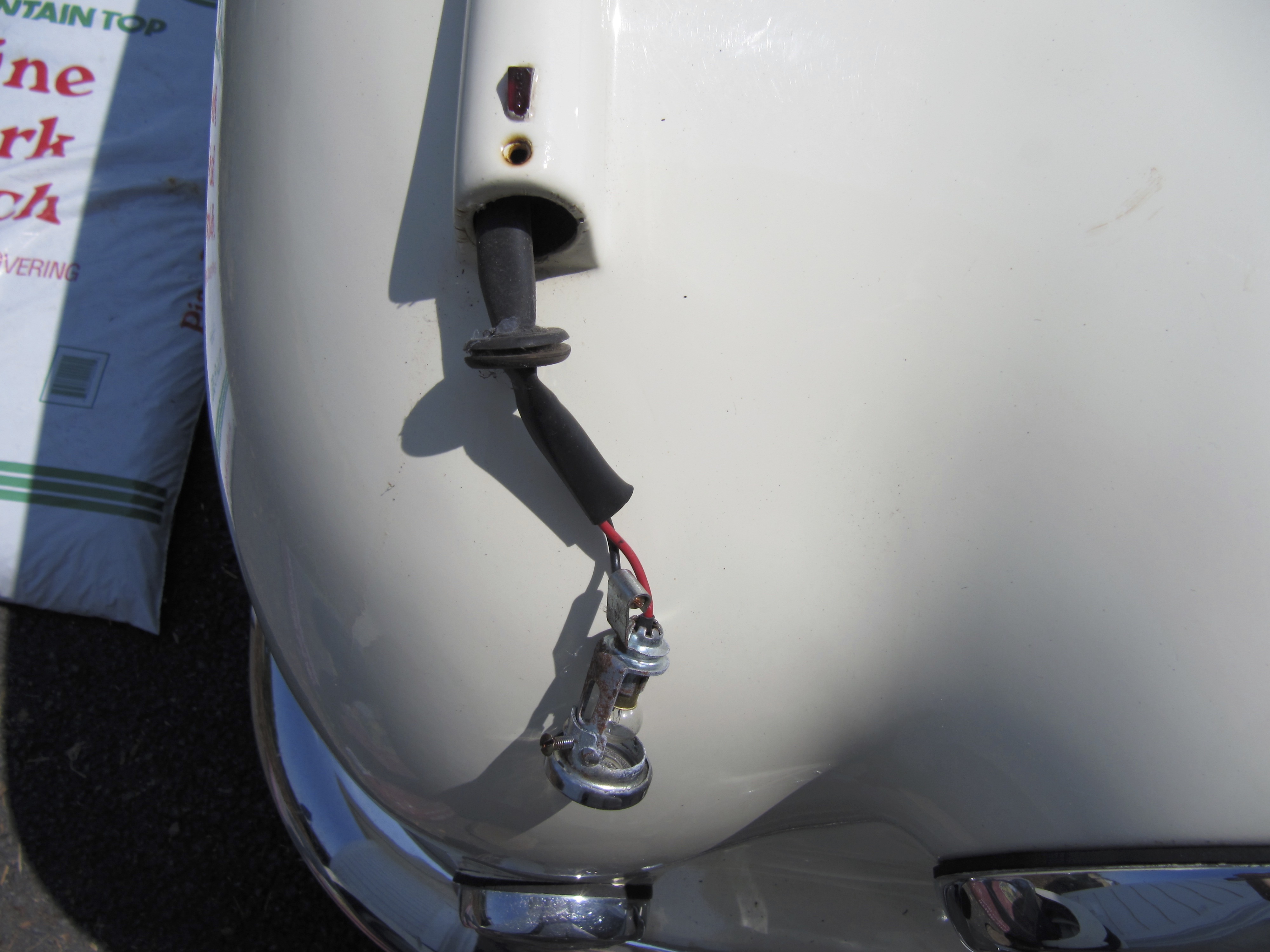
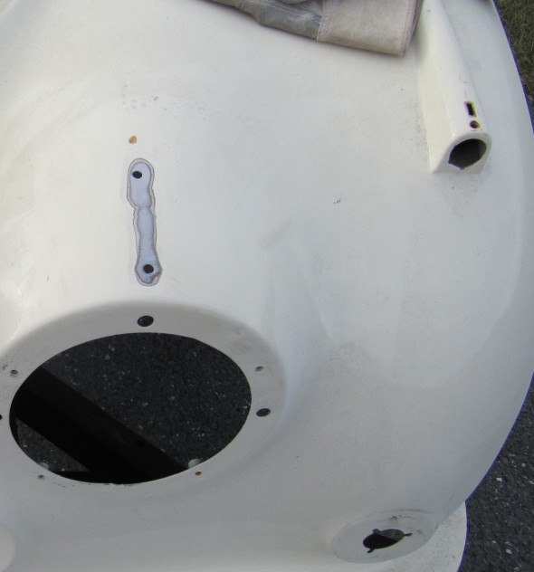
Side Lamps
The MK2 has small side lamps on the top of each front wing. Each lamp has a rubber “O” Ring Gasket between the chrome trim ring and the body of the car, and the lamps are secured to the body with a chrome machine screw. The lamps use 4 watt bulbs C. 12249.
RH Turn Indicator
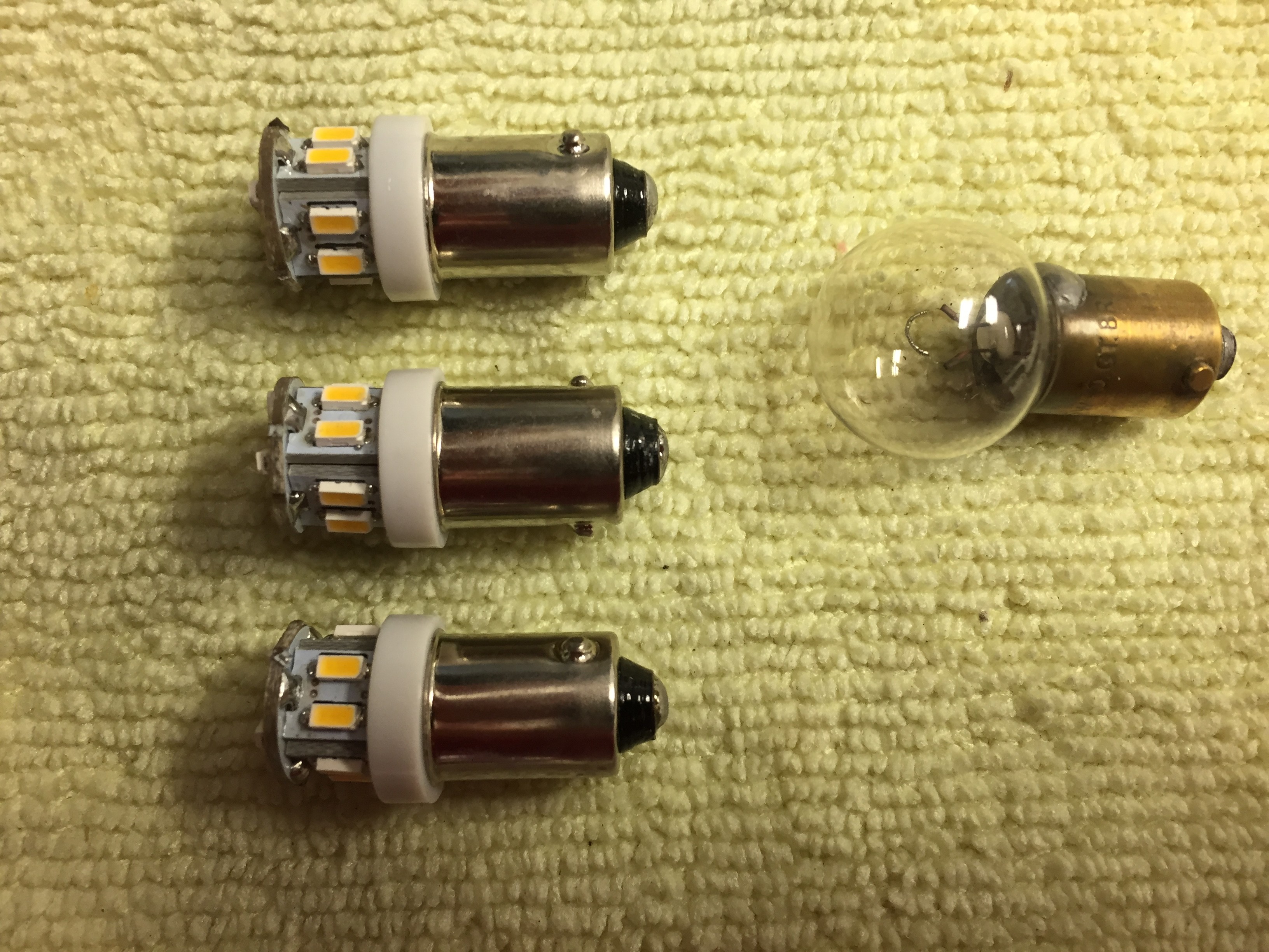
The lamps were in good working order so I just cleaned them, rewired them, replaced the incandescent bulbs with LEDs and new “O” Rings with new chrome mounting screws. The “O” rings that came with that were sourced from SNG Barratt were too thick for my installation. I ended up using metric rings that are 24mm – 2mm and I purchased them from McMaster-Carr. The screws are oval head #6-40 (I believe) x 3/4″.
Sidelamp
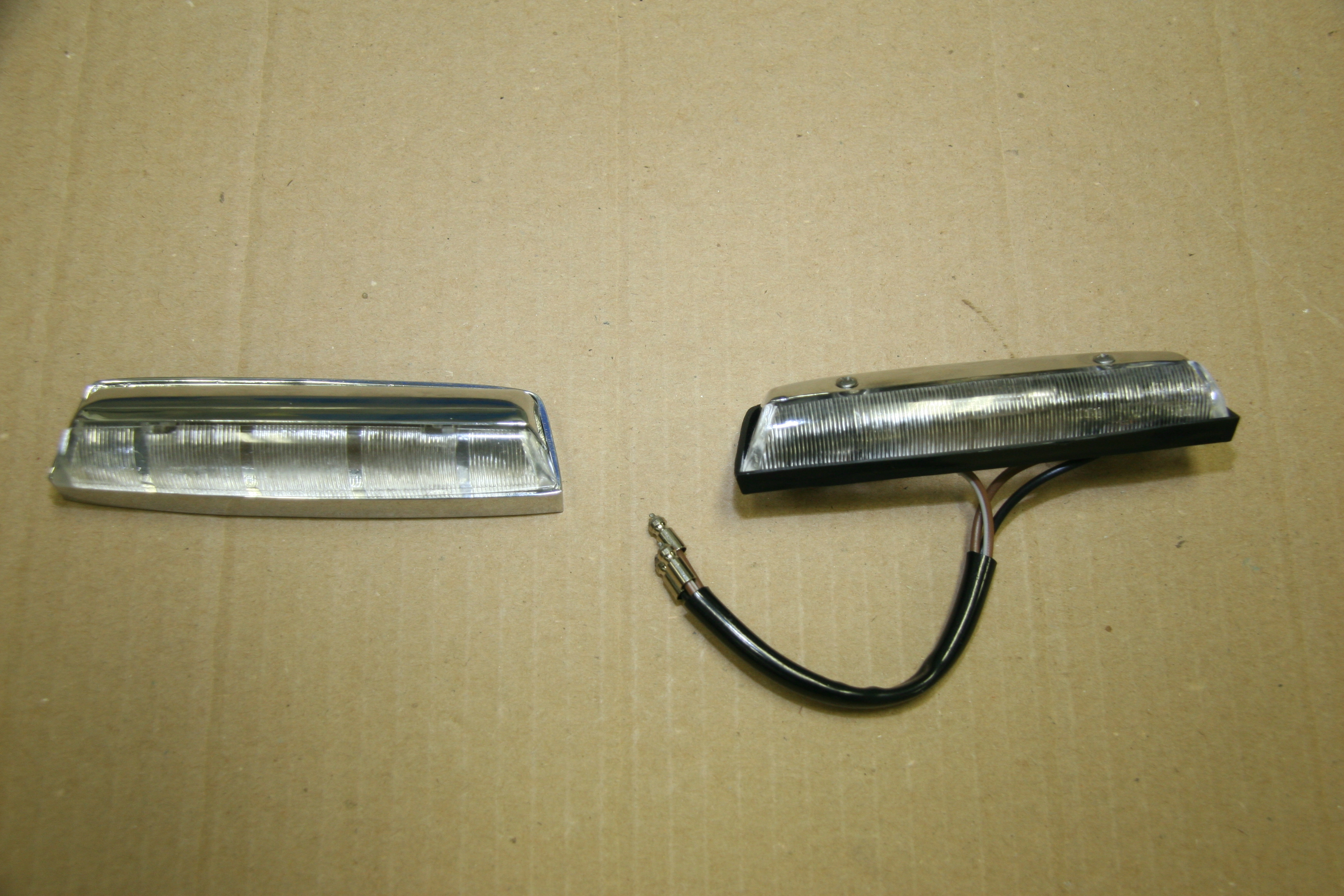
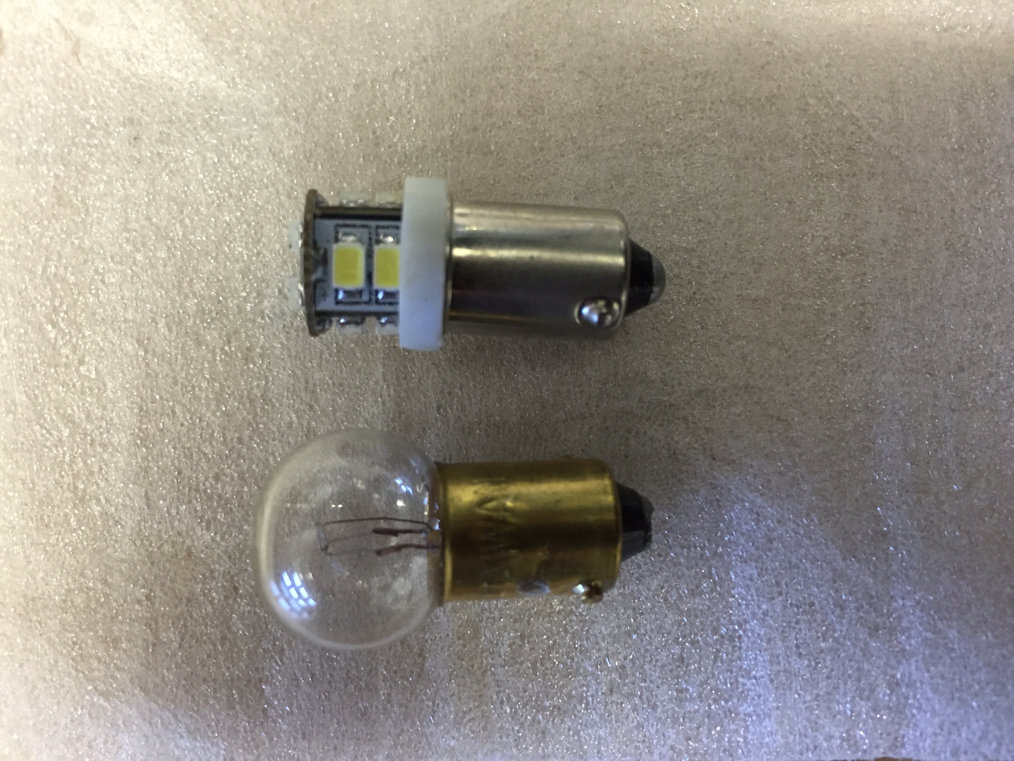
A small red indicator lens for side lamps mounts on the top of each body wing flare for the lights. I ordered new plastic indicators that are held in place by a metal slide clip.
Side Lamps

New LED Bayonet Bulbs
Side Lamp on Body
All new wiring and sleeving was added to the side lamps.
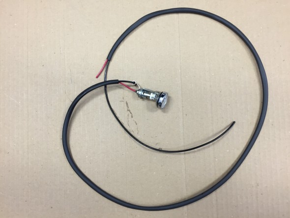
RH Side Lamp Wiring & Sleeving
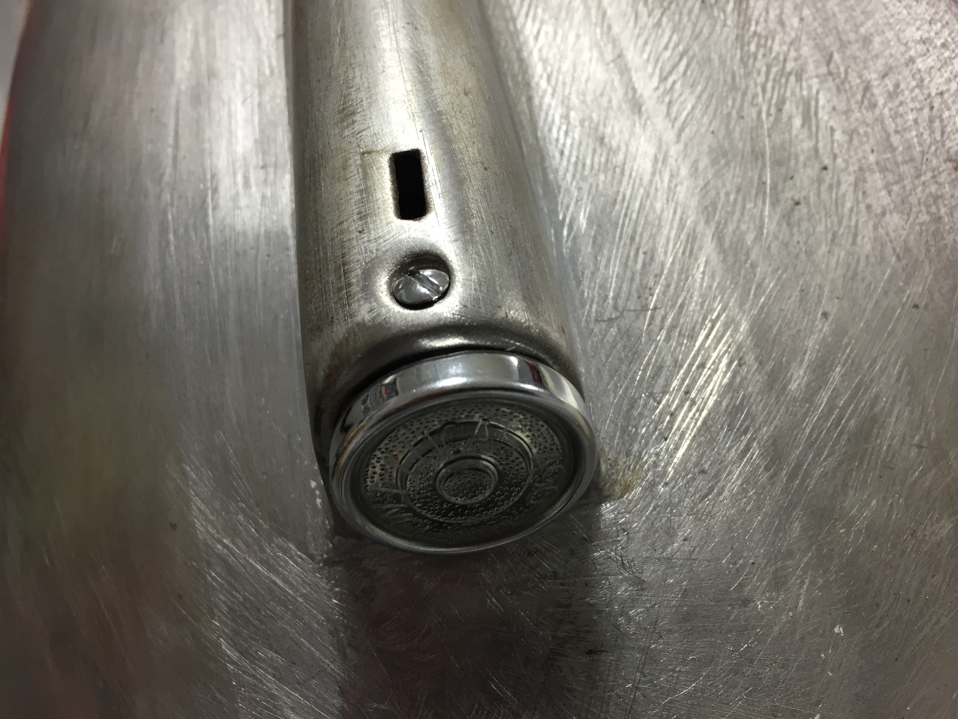
The side lamp is removed from the body by turning the rim clockwise and then withdrawing the lamp. A “bump” in the lamp body must align with a slot in the body.
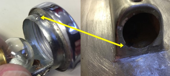
Sidelamp Fitting
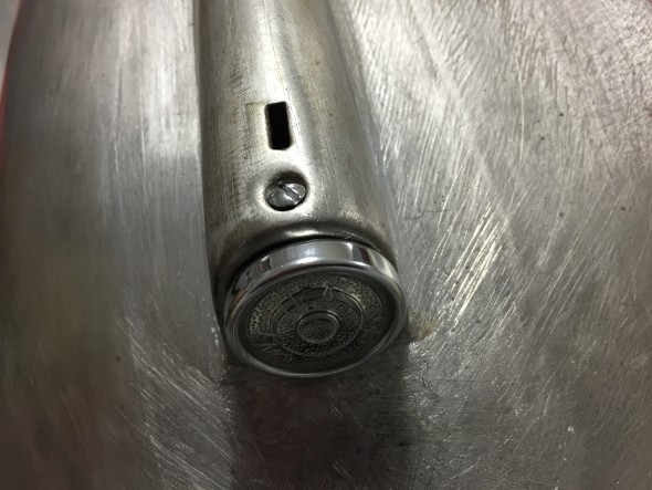
Refurbished side lamps installed
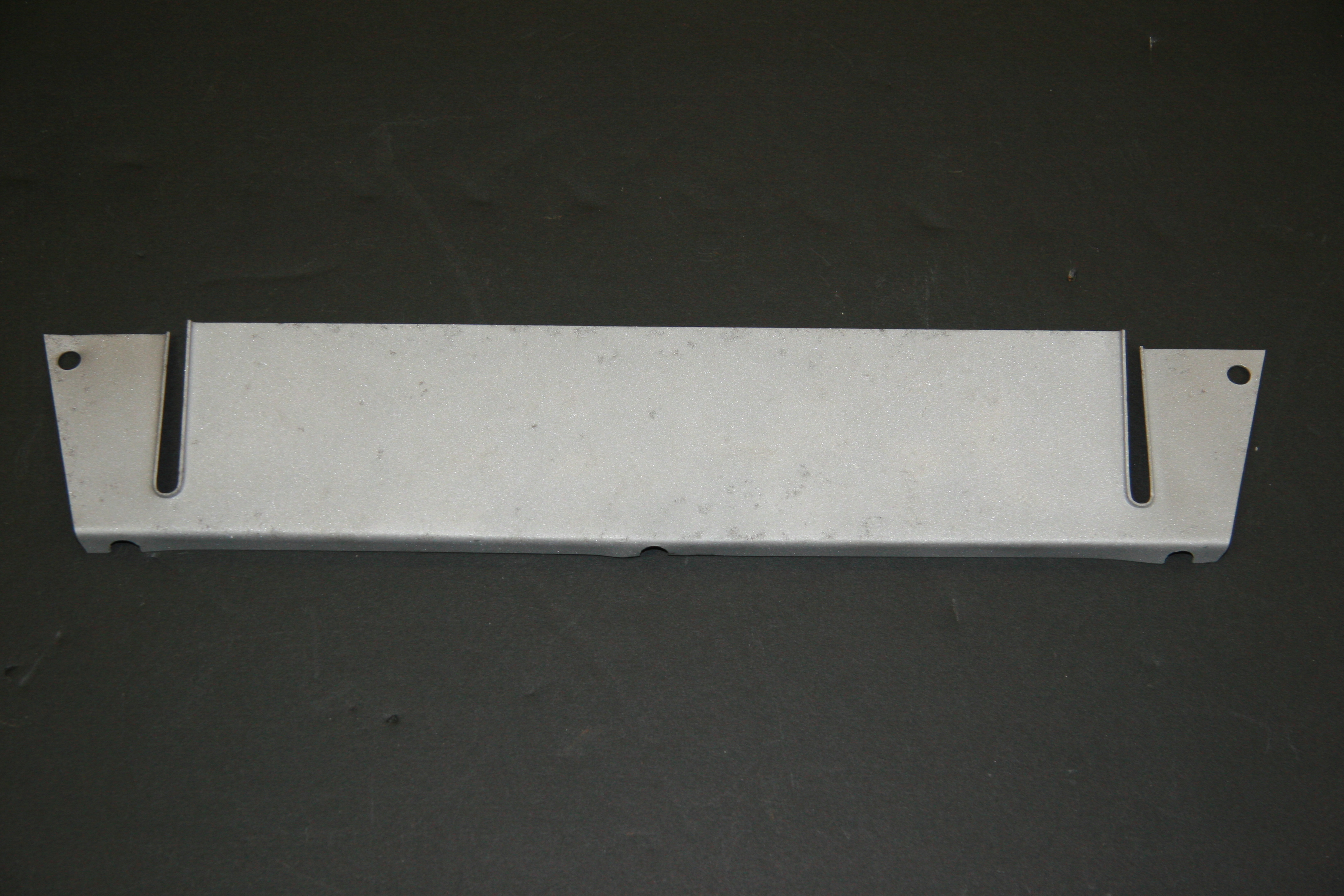
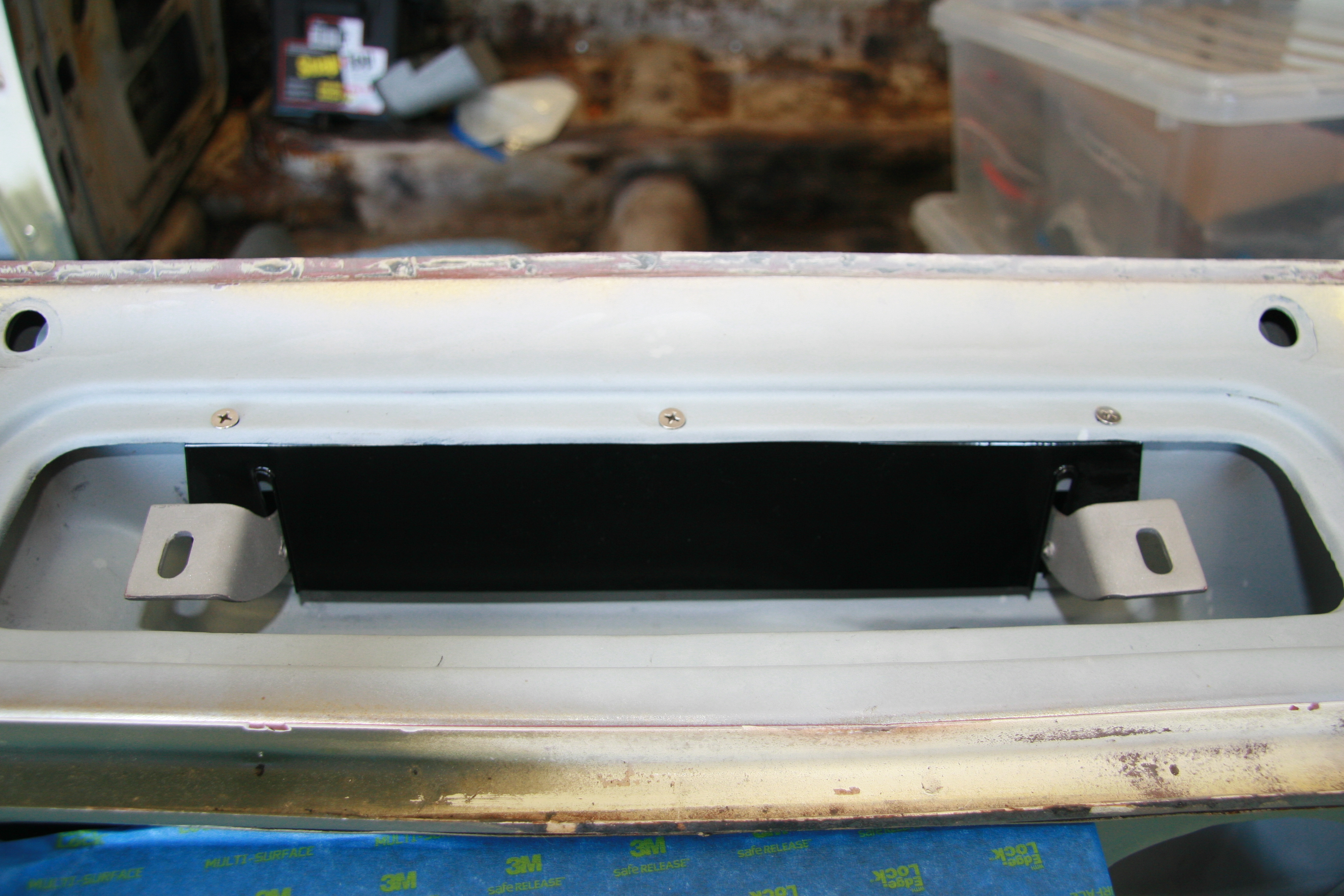
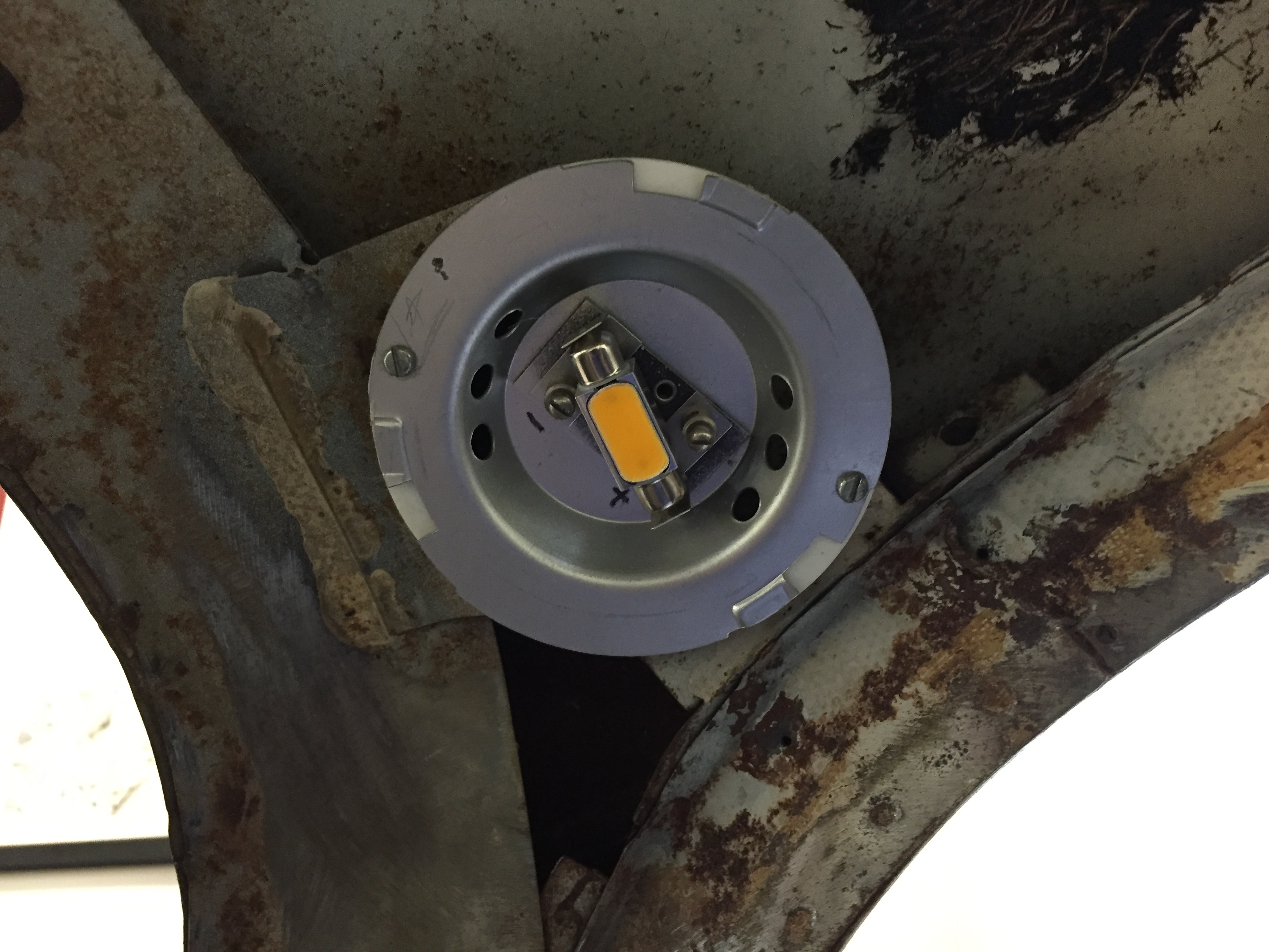
Number plate illumination and reverse lamp
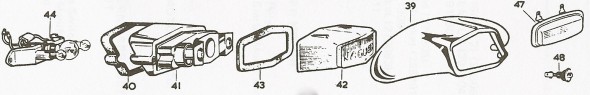
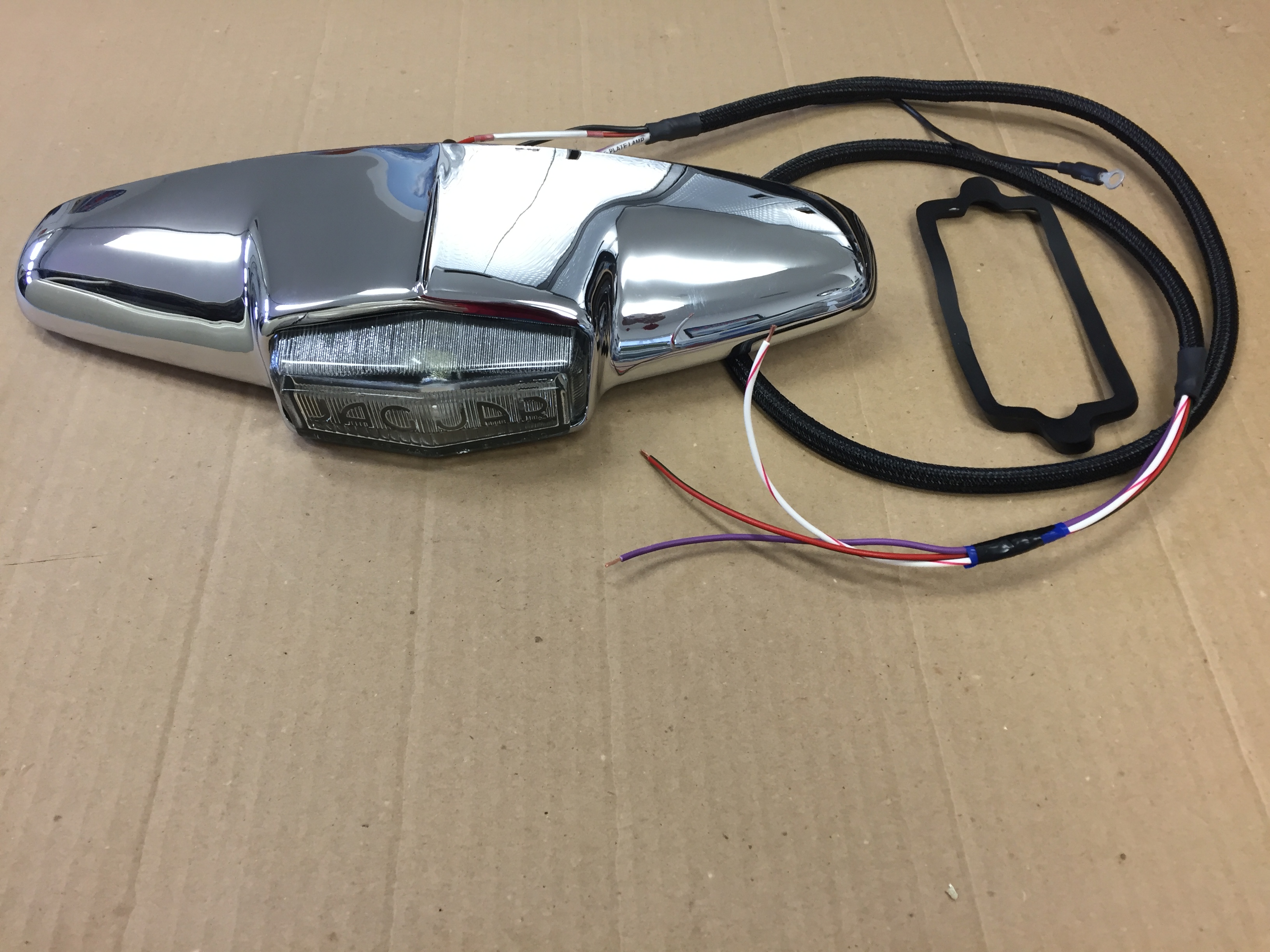
Number Plate Illumination & Reverse Lamp
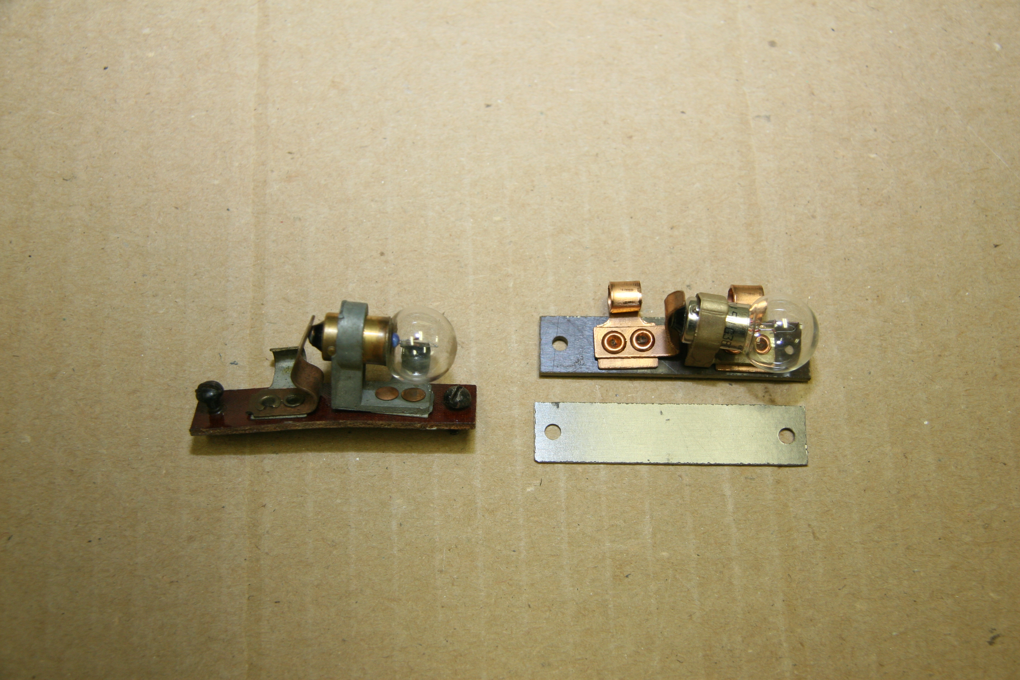
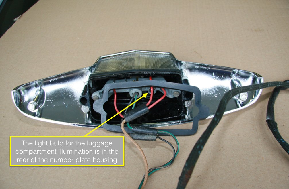
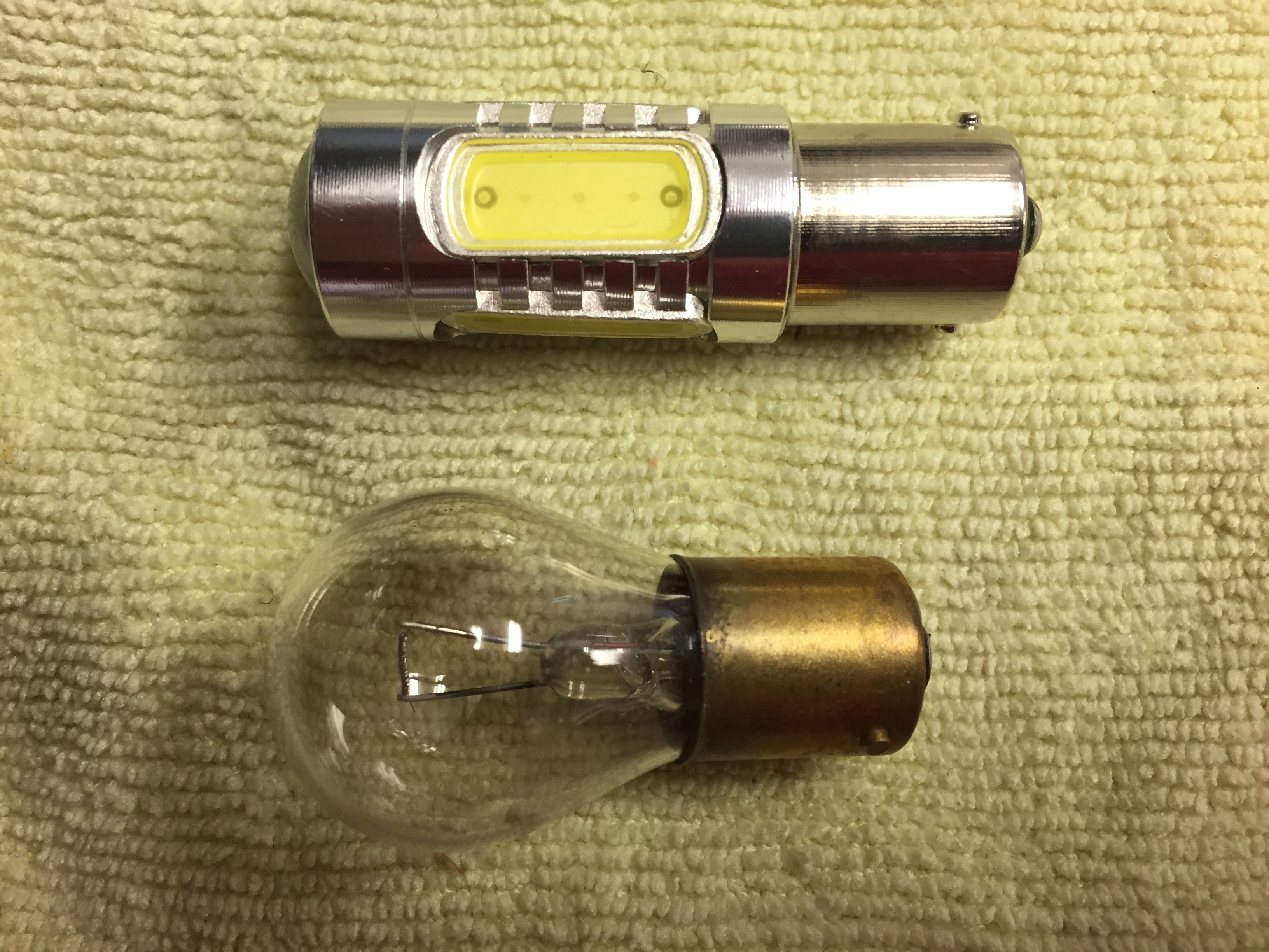
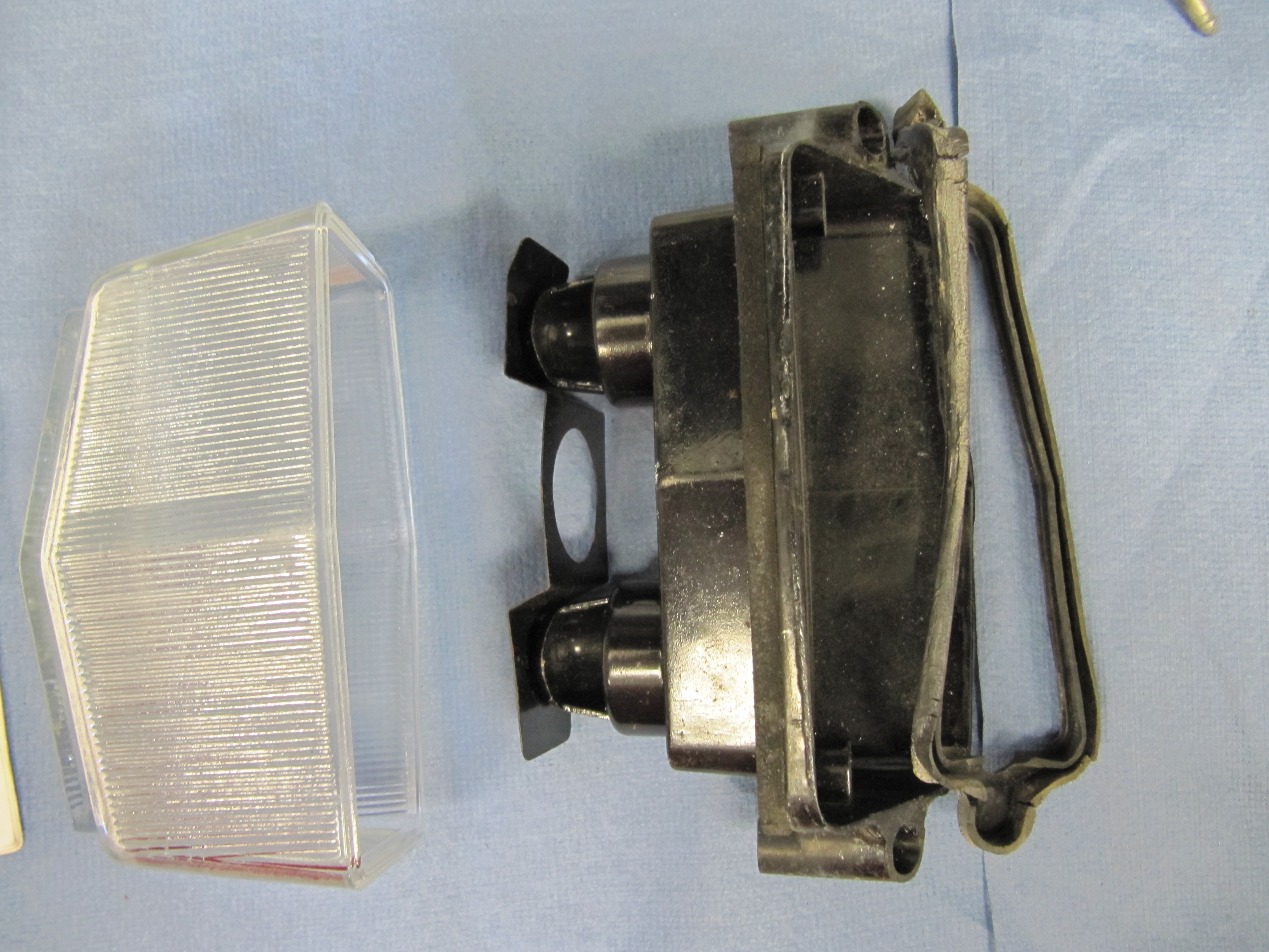
The chrome housing is mounted to the body with a plastic gasket between the two. Within the housing is a plastic shroud assembly and a metal bulb holder. There are three 6 watt bulbs (C.12249) to illuminate the number plate and luggage compartment, I replaced these with “233 Multi LEDs” sourced from 4Sight Automotive. The one 21 watt bulb (C.9126) for the reverse light was replaced with a “382 High Power LED. There is a bulb shield gasket and a gasket between the shroud and the clear glass lens.

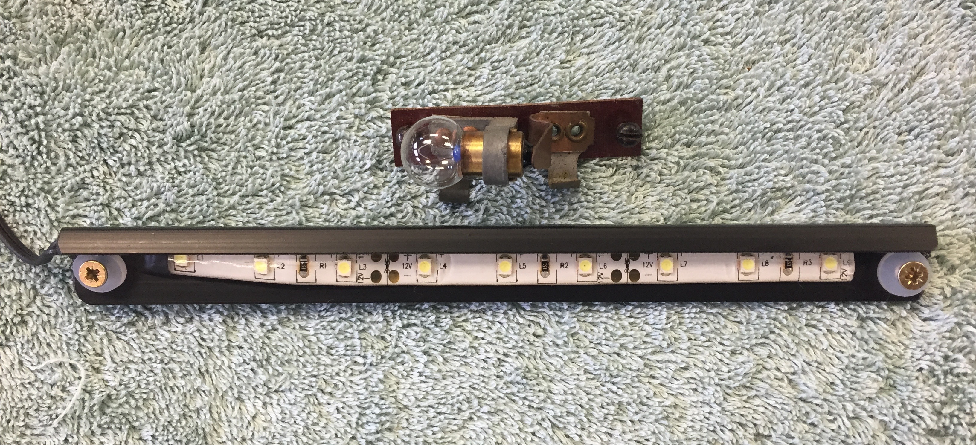
233 Multi LEDs to replace 12v 6w incandescent in boot lamp

382 reversing LED in boot lamp
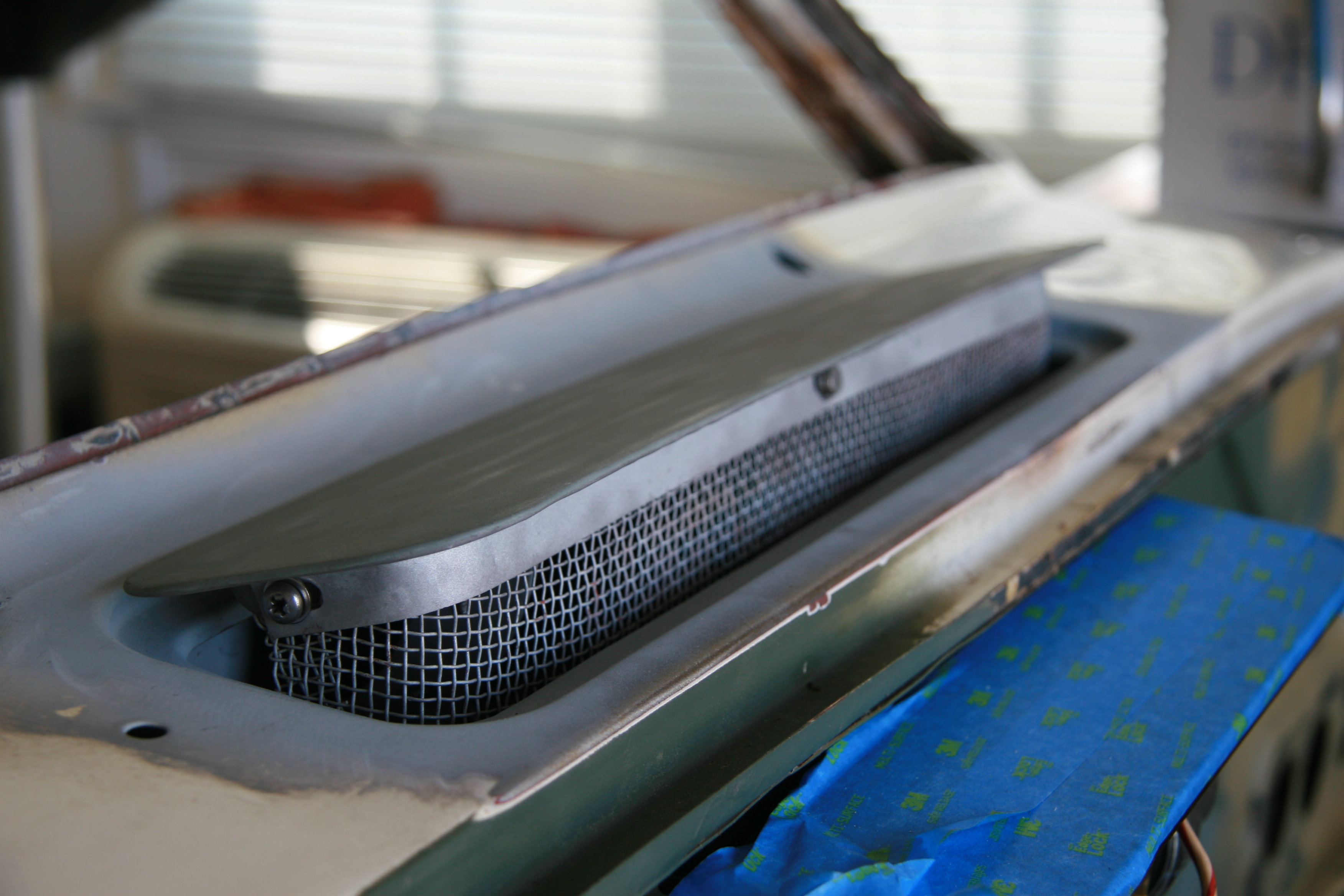
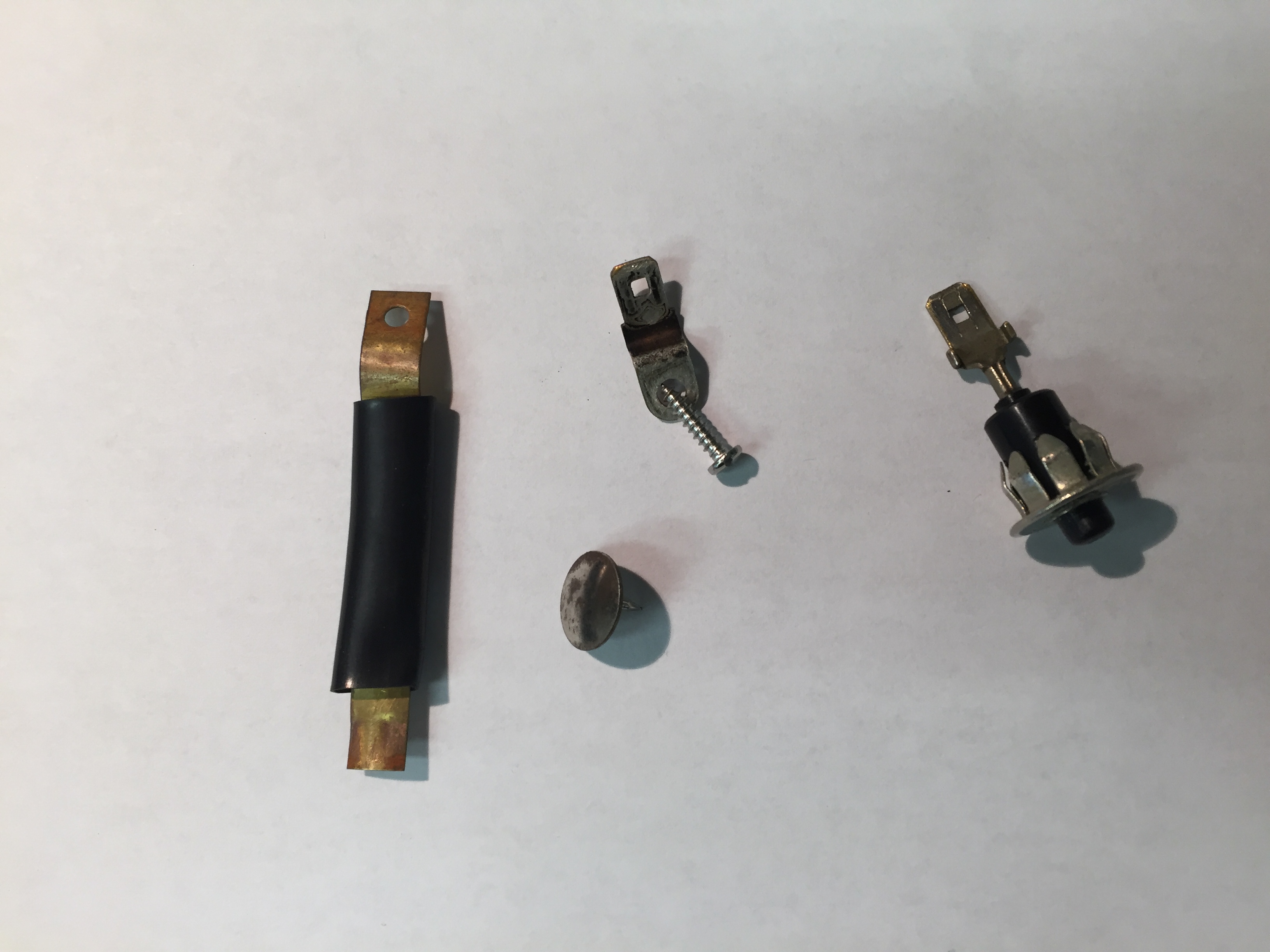
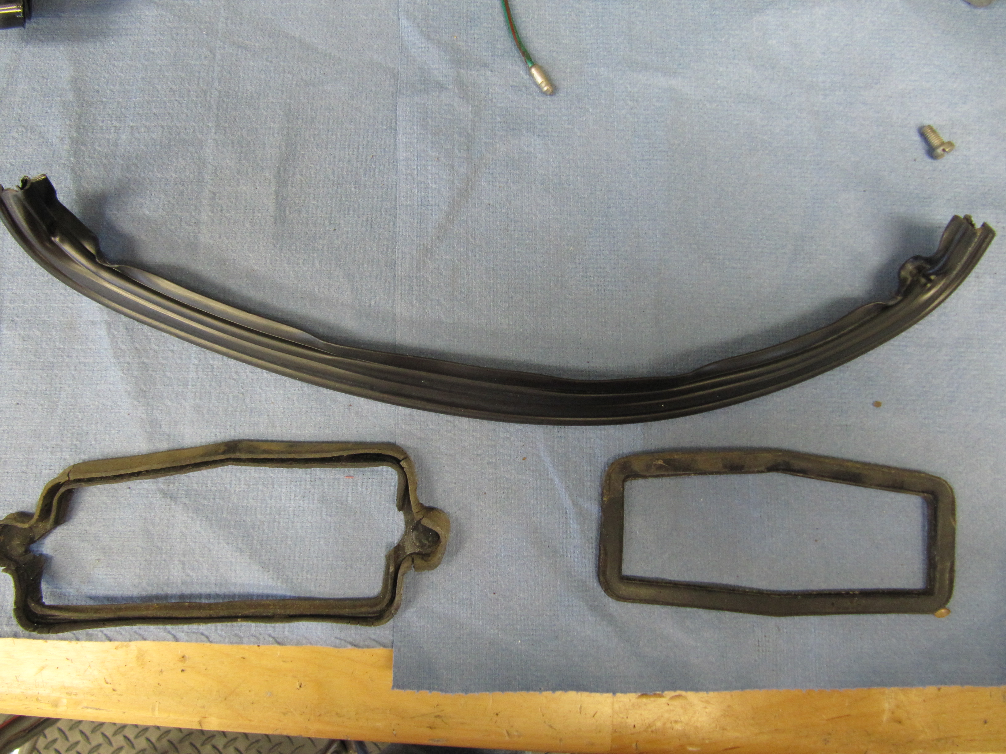
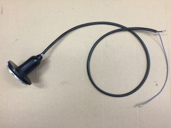
I was able to clean and reuse all of the components with the exception of the rubber gaskets within the lamp which were replaced with new items. The original seal between the lamp and the body was cleaned and renewed. The lamp was rechromed.
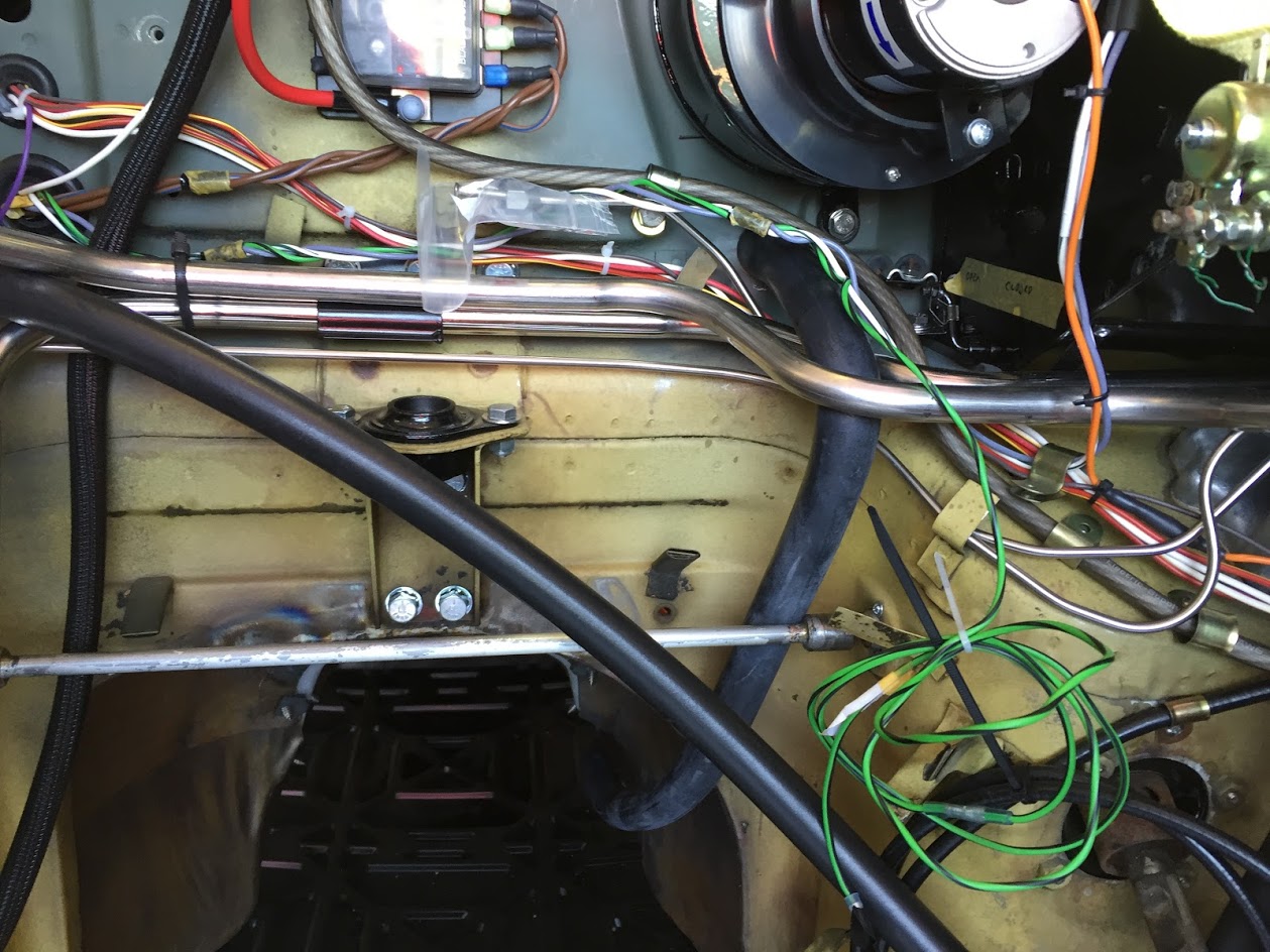
Although the wiring harness was in good condition, I replaced it with new wiring.
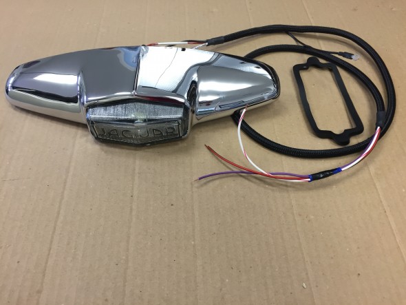
Boot Lamp with new wiring harness
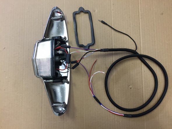
Boot Lamp with new wiring harness
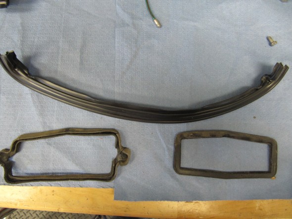
Gaskets and Seals
Shroud and Lens