John’s Initial Drive and Performance Debrief

John came over on Sunday July 20, 2025 to check out the progress on the Bugeye restoration and take the car for its first real drive on public streets. We had a wonderful visit and John and I got to experience Donald Healey’s little car on the open road. Of course, this also gave us the opportunity to assess what was working well and what needed improvement.

First drive on the open road

The car performed without incident – always good! The engine ran very smoothly and sounded great but did not have the acceleration we expected. The suspension offered a plush ride compared to what John had been used to pre-restoration. New springs, rebuilt shocks, new bushings everywhere, a new steering rack, new Pirellis and reupholstered seats with new foams all contributed to the improved ride. The 3.9 differential that replaced the 4.2 may have had some effect on low end torque.

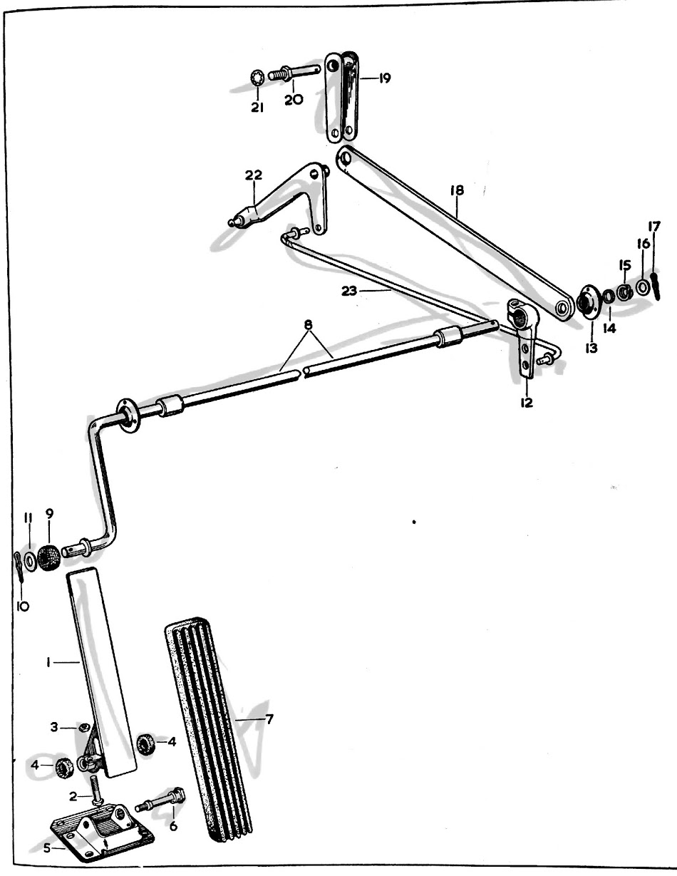
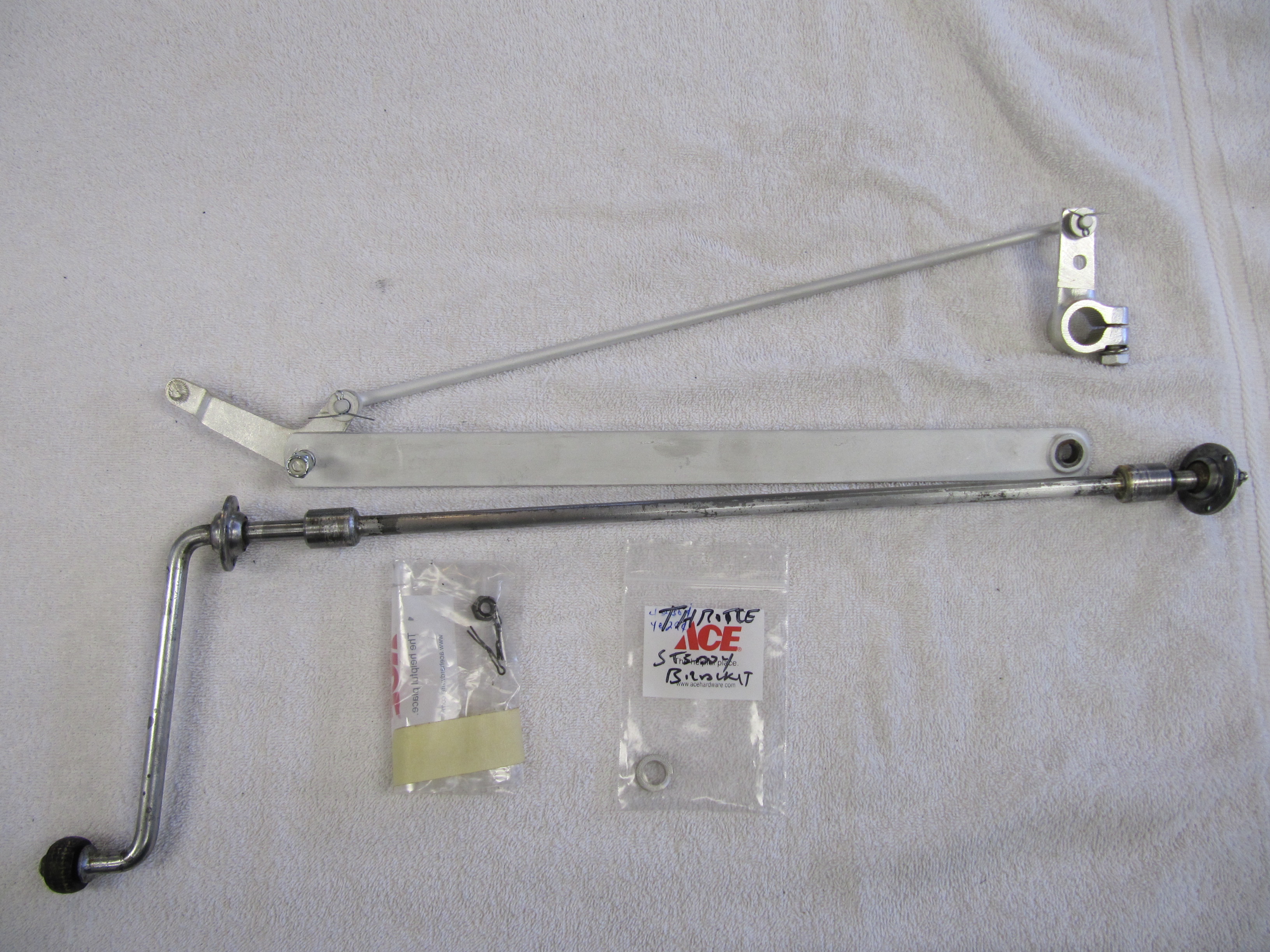
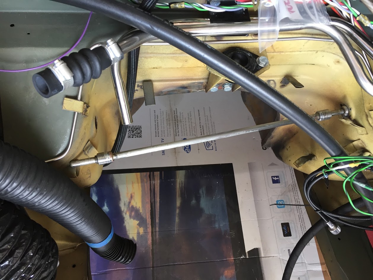
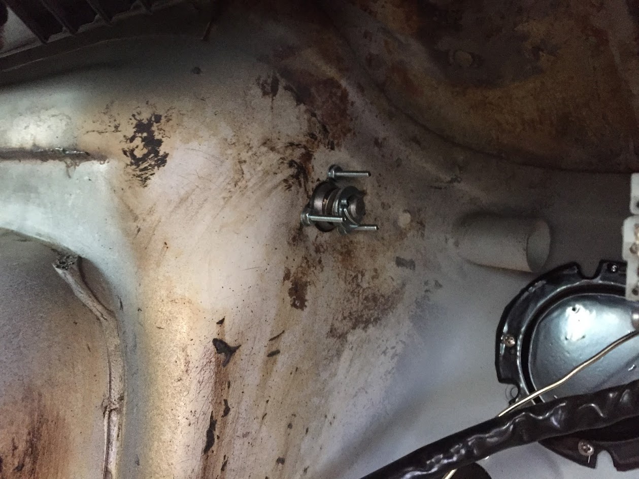
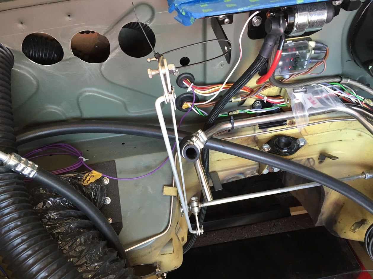
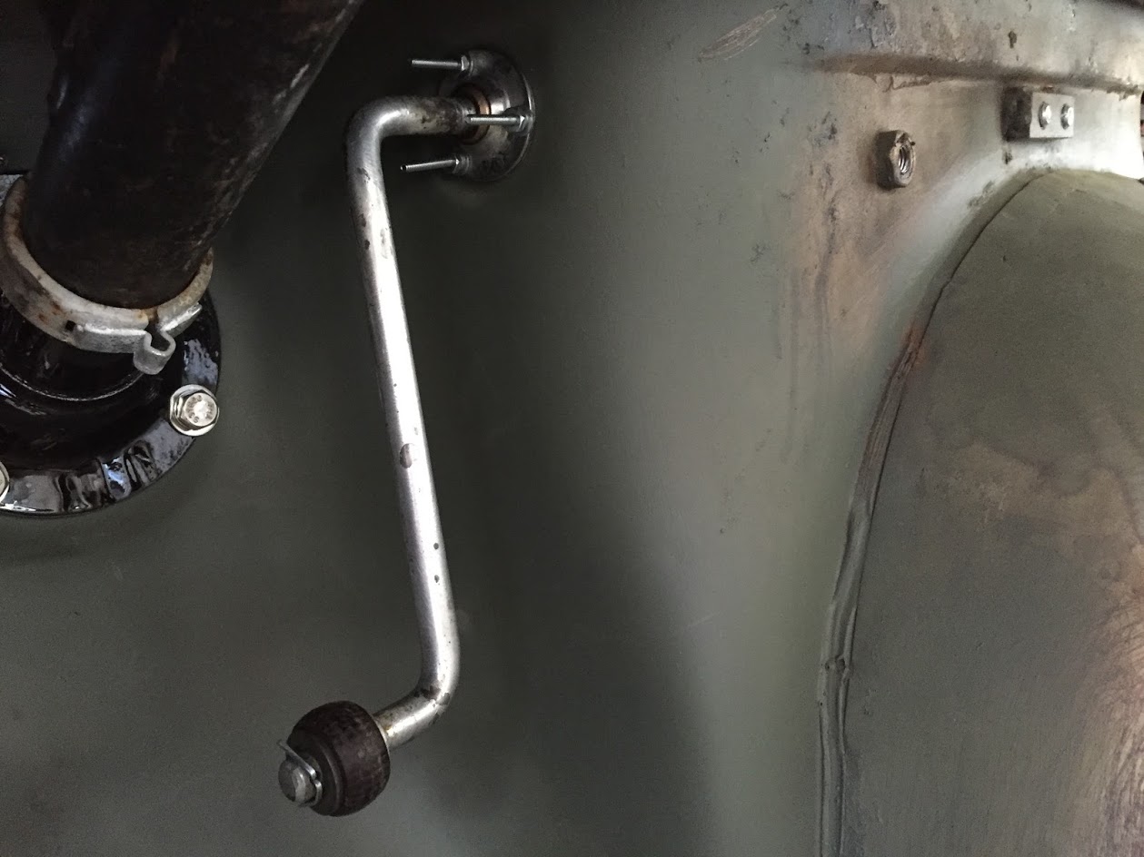
After John returned to his home on the other side of Florida I spent some time trying to analyze how we lost some performance. I discovered that the butterfly in the carburetor was not fully opening when the accelerator pedal was depressed. This was due to the addition of the Speedwell Engineering hanging accelerator pedal assembly, combined with layers of dynamat insulation, aluminum insulation, plush carpet, and a rubber Matthau all combined to prevent the accelerator pedal from completing its natural travel. As the attache video shows we removed the aluminum duct insulation and cut away the offending carpet and rubber mat thereby freeing up the pedal to full open the carb butterfly. 

We also substituted a fast-drop carb piston damper LZX 2085 for the original. We are hoping that these improvements and substitutions will give us the performance we are looking for. All of the spark plugs look great with a tan burn residue. Timing and fueling appear to be spot-on.

Bugeye Restoration Video Episode One Hundred-Fourteen shows some of the initial drive of John’s Bugeye:

https://vimeo.com/1105259492/319edbc3f6?share=copy


Accelerator pedal

The accelerator pedal in the Bugeye was mounted on the floor board as seen in the illustration below:

Sprite Accelerator Pedal

We have decided to hang the pedal from the shaft rather than mounting it on the floor and we purchased a kit from Speedwell Engineering that has a throttle return spring so that the mechanism is not dependent upon the throttle plate return spring on the carburetor. 

Episode Eighty-nine of the Bugeye Restoration Videos shows the new pedal arrangement installed in the car:

https://vimeo.com/1029000934/d39495fc82?share=copy

Accelerator Controls

Accelerator Pedal Assembly

The accelerator pedal assembly was in good shape. I replaced the rubber pad on the accelerator pedal with a new one. I left the set screw restricting the pedal travel as it was found, as well as the two felt washers located at each side of the pedal boss.

The bracket assembly was cleaned and painted with POR 15. It is secured to the floor with four pointed 1/4″ – 28 x 5/8″ hex head bolts with split washers. The pedal is connected to the bracket with a 1/4″ fulcrum pin, flat washer and 1/4″ – 28 nylock nut.

Accelerator Pedal Assembly

Accelerator Pedal Assembly

Bracket Assembly, Mounting Accelerator Pedal to Floor

Bracket Assembly, Mounting Accelerator Pedal to Floor

Accelerator Shaft Assembly

The image below depicts the components of the accelerator shaft assembly:

Accelerator Pedal Shaft Assembly Graphic

Accelerator Pedal Shaft Assembly Graphic

The shaft was slightly bent so I straightened, cleaned and polished it. The spherical bearing assemblies will be lubricated and reused and will be installed with new pop rivets to the body. The throttle lever, screws, spring washers and flat washers; the steady bar between the cross shaft housing and the connecting link; the bell crank lever assembly; and the control rod assembly were all cleaned and clear cad plated.

Accelerator Controls

Accelerator Controls

In anticipation of installing the engine into the car for testing, I installed the accelerator shaft assembly into the car. This would be more easily done prior to the installation of the steering column, but I was able to successfully work around it.

Having removed the split pin, flat washer, spring washer and the RH spherical bearing from the shaft, I inserted the accelerator shaft from the driver side into the engine compartment.

Installing the Throttle Shaft Assembly

Installing the Throttle Shaft Assembly

I then installed the throttle lever, the steady bar (with the bell crank lever, and the control rod assembly, linking the cross shaft lever and the bell crank lever), the RH spherical bushing onto the shaft and and slipped the shaft into the mounting hole on the RH side of the car.

Pedal Shaft Assembly

Pedal Shaft Assembly

Because I am only temporarily installing the throttle assembly in the car, I used #4 machine screws with flat washers, lock washers and nuts to hold the spherical bearings in place at both mounting points. Upon final assembly, pop rivets will be used.

RH Spherical Bearing in Place

RH Spherical Bearing in Place

In the passenger side (RH) footwell, I then slid the distance piece, spring washer, and flat washer onto the shaft followed by a split pin to secure the shaft assembly.

The assembly was then zip tied out of the way for engine install.

Accelerator Shaft Assembly

Accelerator Shaft Assembly

This is the LH side of the assembly prior to installing the accelerator pedal.

Accelerator Pedal Shaft Assembly and LH Spherical Bearing and Pedal Shaft Roller

Accelerator Pedal Shaft Assembly and LH Spherical Bearing and Pedal Shaft Roller

Finally, the pedal assembly described earlier was mounted to the driver’s side floor with four 1/4″ – 28 x 1/2″ hex head bolts with lock washers. These bolts are fastened into captive nuts welded to the floor underside.

Accelerator Pedal Assembly Mounted to Floor

Accelerator Pedal Assembly Mounted to Floor